

Page 1
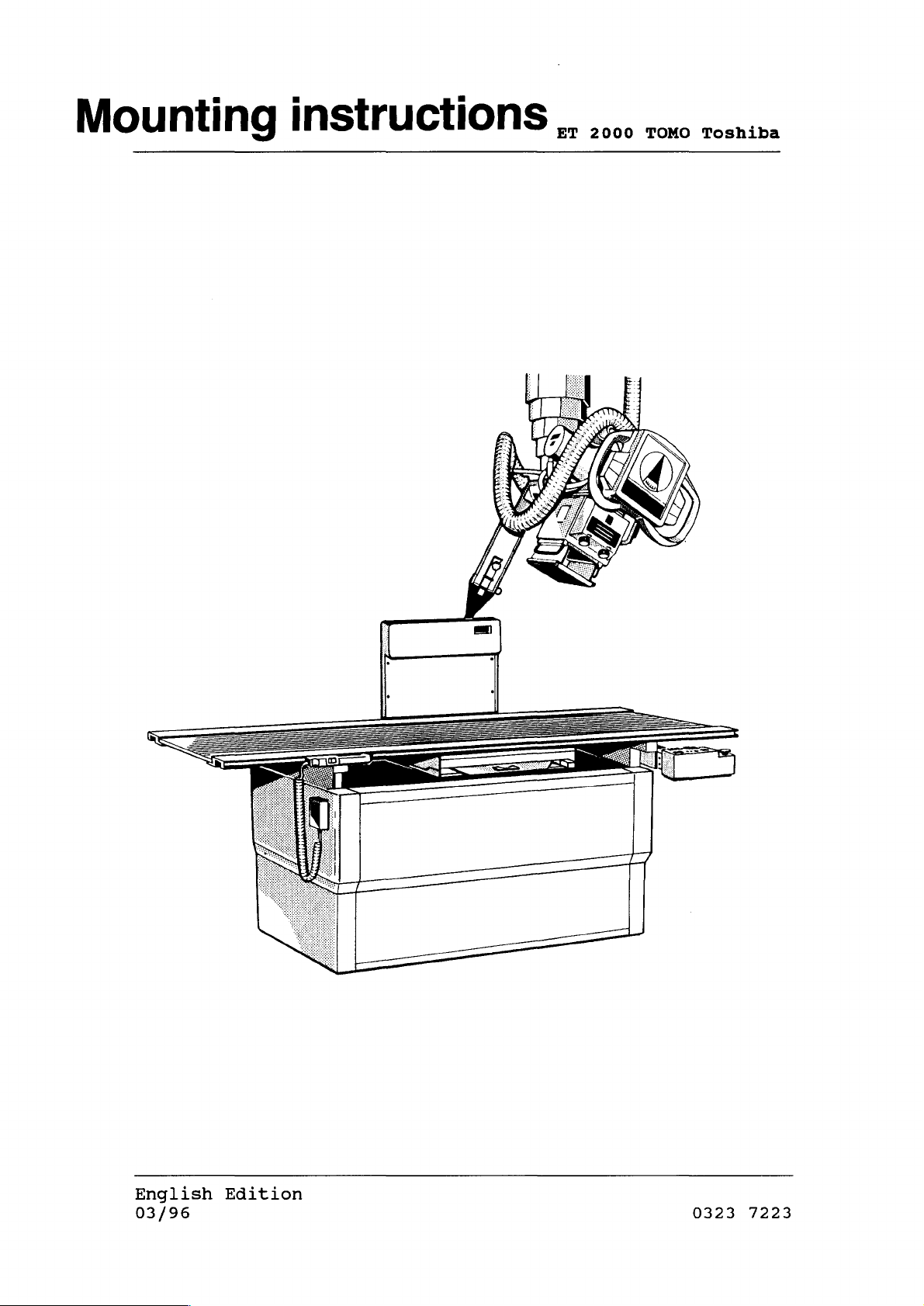
Mounting
instructions,
sn:
English
03/96
Edition
0323
7223
Page 2
PAGE
p
e
Technical
Data
ピロ
ビ
νι
δω
ビビ
ビビ
ビビ
σσ
O
ποσο
ビビ
2.
2.1
2.2
2.3
2.4
2.5
2.6
2.7
2.8
2.9
2.10
2.10a
2.11
2.12
2.13
2.14
2.15
2.16
2.17
General
General
Measures
Component
Equipment
Mains
Measuring
Wiring
Power
Physical
and
Safety
Specifications
and
Designations
Checklist
Connection
Instruments
and
Supply
Location
Electric
Installation
Uncrating
Removal
Mounting
Mounting
Mounting
Mounting
Mounting
Mounting
Drive
Mounting
of
of
of
of
of
of
of
Belt
of
Modifikation
Mounting
of
Installation
Installation
Installation
Reinstallation
Installation
Mounting
of
Procedures
Weights
Current
Field
Covers
Bracket
Tomo
Fulcrum
Tomo
Tomo
Drive
tighten
Tube
on
Tomo
of
of
of
of
of
Covers
for
Data
Required
Diagrams
of
Electrical
Installation
Coupler
Tower
Control
Drive
Belt
on
to
Coupler
DST
100A
Interface
Electrical
Relais
Tomo
Board
Marks
Covers
Tomo
Marks
Shipment
Box
Ceiling
Ceiling
Support
Unit
to
Components
Diagrams
Column
Rail
Arm
Ceiling
WW
AUF
EN
PoONNI
14-19
20
20
20
22
22
22
23
23
23
23
24
25
25
25
26
26
27
27
3.
3.1
3.2
3.3
3.4
4.
4.1
4.2
4.3
4.4
0323
Adjustments
Adjustment
Setting
Timing
Switch
Technical
Mechanical
Functional
Spare
Parts
Inspection
7223
of
of
Layer
of
Exposure
Flap
Adjustment
Maintenance
and
Tests
Certification
Fulcrum
Height
Cycles
Electrical
-
to
2-
Film
Tests
Plane
27
28
29
30
31-32
33
34-36
27
03/96
Page 3
1.
TECHNICAL
DATA
1.1
In
lation
the
lay-out
During
ground
properly
The
components
in
General
the
of
provisions
installation
wire
protective
the
Regulations
and
No
than
If
accident
work
42
it
is
movements
tion
procedure,
pletion
Federal
rooms
plan.
made
and
wiring
may
be
V
(Peak
necessary
of
of
these
Safety
Notes
Republik
used
of
VDE
connections
before
ground
the
diagram.
of
professional
prevention
performed
Voltage).
the
equipment
it
must
movements.
for
it
the
wires
power
to
turn
be
of
Germany,
medical
Standard
is
important
provided
equipment
supply
associations
must
on
parts
in
shut
0107.
betweem
be
carrying
on
the
the
down
the
electrical
purposes
Consult
|
that
by
the
is
the
are
connected
observed.
power
course
immediately
must
conform
installation
all
manufacturer
started
individual
protective
concerning
a
voltage
for
execution
of
the
after
instal-
are
up.
system
as
shown
safety
higher
installa-
com-
to
of
1.2
Note:
The
posures
If
stalled.
General
motor
supplied
Film-Focus
tomographic
Fulcrum
Plane
Angles,
Speeds,
Height
Specifications
driven
with
the DST
with
Distance
exposures:
Range:
Indication:
Tomography:
Tomo
Tomo
Zono
40°
40°
8°:
ET
the
and
and
2000-Tomo
100A.
ET
(FFD)
20°
fast:
20°
slow:
2000,
for
device
several
100
O - 24
Digital
40°
c.
c.
c.
allows
cm
and
24
12
9
parts
cm,
Display
20°
cm.p.s.
cm.p.s.
cm.p.s.
tomographic
are
motor
Zonography:
driven
ex-
prein-
8°
03/96
-3-
0323
7223
Page 4
Approximate
Exposure
Times:
Plane
Height
24
cm
18
cm
12
cm
6
cm
1.3
1.3.1
40°
c.2,1
c.2,1
c.2,5
c.2,6
Measures
1
Crate
Gross
Net
weight
During
Temperature:
Humidity:
Air
pressure:
<<
sec
sec
sec
sec
and
weight
regular
40°
c.4,1
c.4,6
c.5,0
c.5,2
Weights
1350
c.53
c.
c.
work
<
sec
sec
sec
sec
125
58
for
mm
in.
kg
kg
20°
c.1,05
c.1,1
c.1,25
c.1,3
Shipment
x
x
c.30,7
274
127
-25
5%
700
<<
sec
sec
780
lbs.
lbs.
to
to
hPa
sec
sec
70?
95%
mm
to
20°
c.2,1
c.2,3
c.2,5
c.2,6
x
in.x
1100
600
<
sec
sec
sec
sec
mm
c.23,6
hPa
ピロ
QQQOQ
ビビ
in.
“ou
ο
ο
νι
ω
sec
sec
sec
sec
During
transport
Temperature:
Humidity:
Air
pressure:
10°
20%
700
to
to
hPa
40°
80%
to
1100hPa
0323
7223
03/96
Page 5
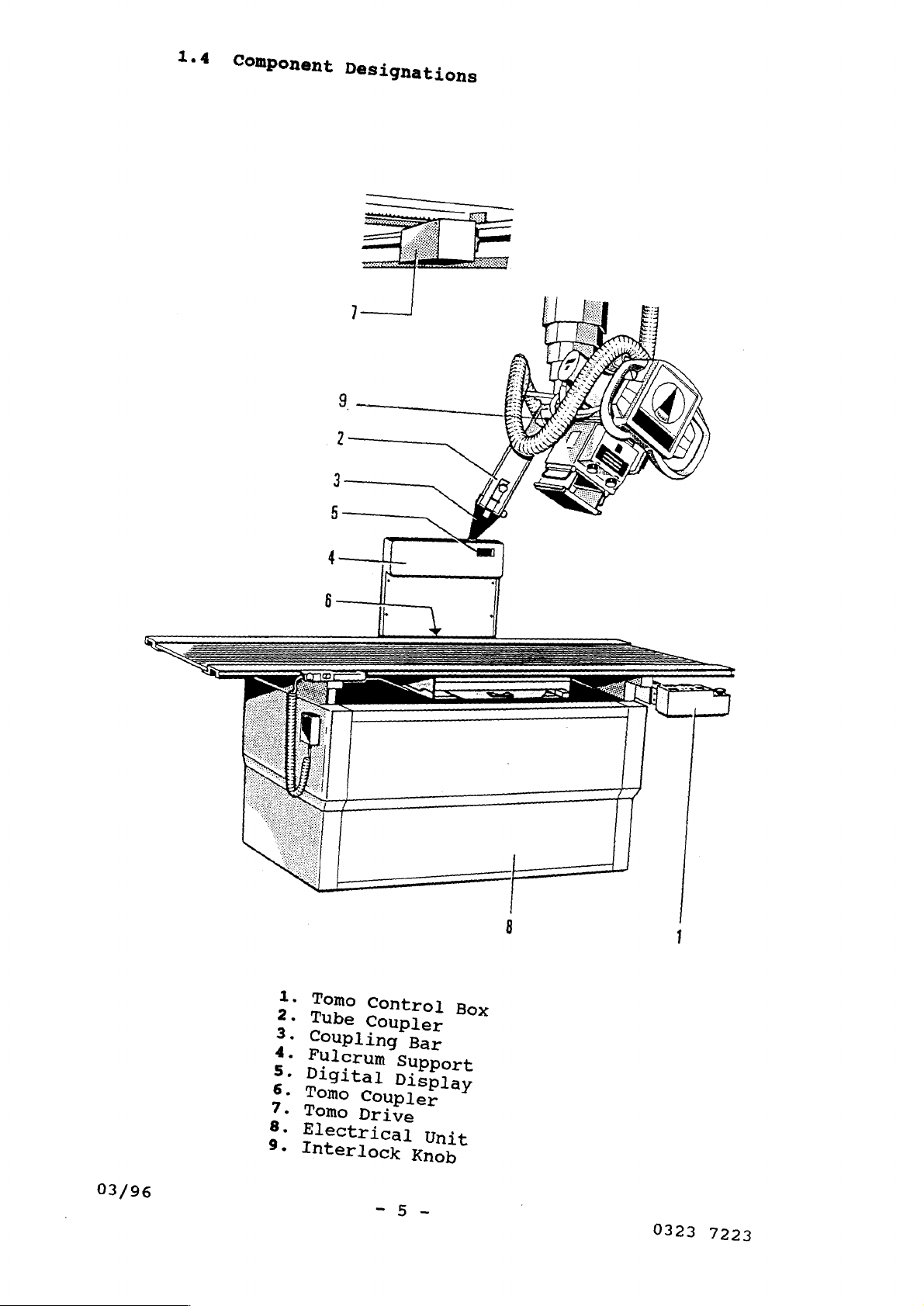
1.4
Component
Designations
ο
Tomo
pa
Tube
Coupling
BUN
Fulcrum
Digital
OU
Tomo
Tomo
au
Electrical
©
Interlock
Control
Coupler
Support
Display
Coupler
Drive
Box
Bar
Unit
Knob
03/96
0323
7223
Page 6
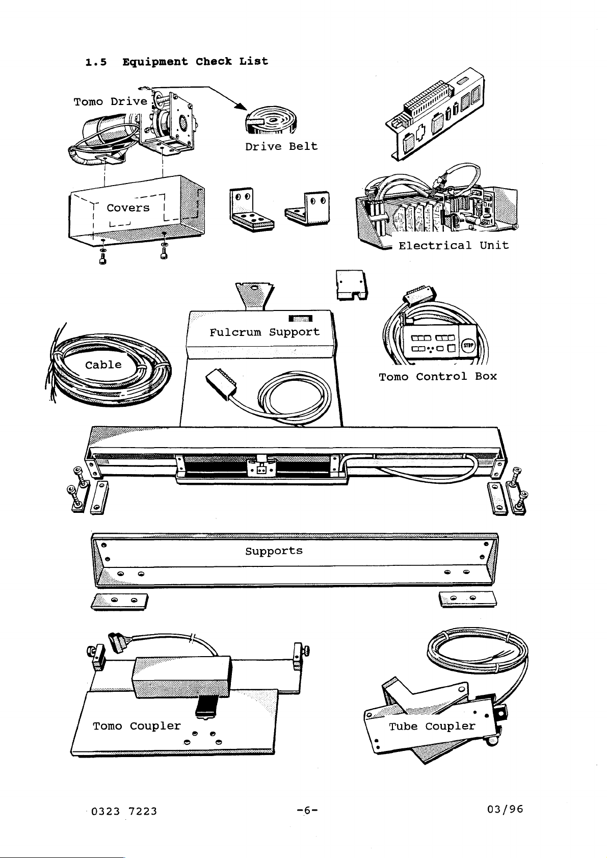
1.5
Equipment
Check
List
Supports
0323
7223
—6-
03/96
Page 7
1.6
The
of
Mains
mains
the
ET
2000.
Connection
connection
Data
is
carried
out
via
plug-in
connectors
Mains
Frequency:
Nominal
Connection:
Nominal
1.7
Air
Phontom
Measuring
Level
Current:
Capacity:
Instruments
230
50/60
A
1
0,2
Required
V
(2)
KVA
or
Hz
115
V
03/96
-7-
0323
7223
Page 8
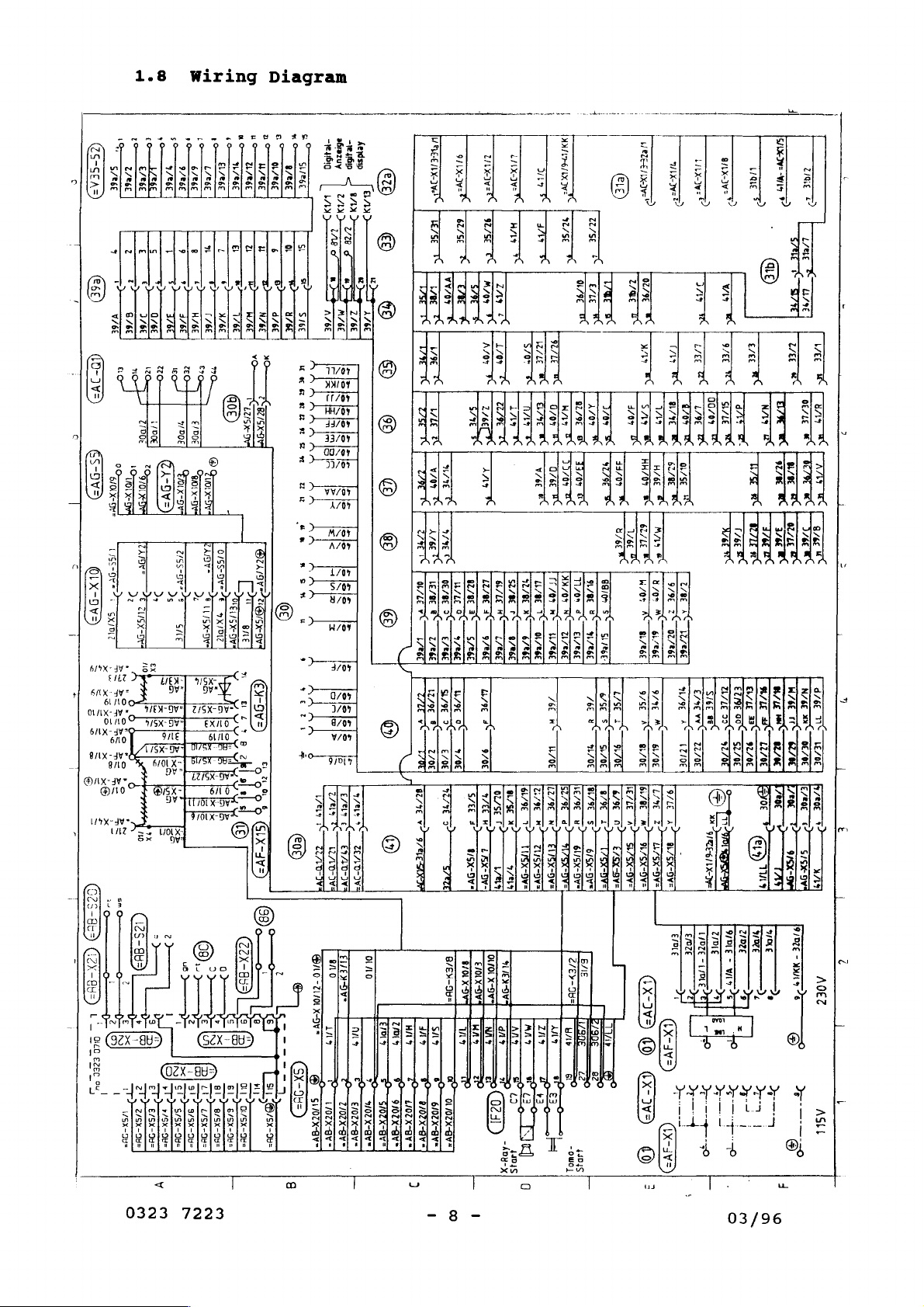
1.8
W
1r1
ing
Diagram
"ET
poe
Le
so
ε
(GS-SEA3)
で
0003
i
SAe6E
LE
#/86E
È
6€
:
!
|
7
Tot
(666)
666
i
+
8/6£
V/BE
5
Е
D
>
>
076€
2/66
1
<)
1768
9
,
376€
=
ro
o
一
一
L/e6E
60966
二
一
+
이
6
T
H76E
T/6E
o
EL/e6€
El
L
ER
$
2
176€
メ
/6E
4/26
È
Y
yi
(V)
;
【0-
う
Ys
iz
。
:
1
se
zzo-
nol
mm
O
7750;
“DOE
ul.
で
5-9Y
|
c
|
う
EXD
FDO
《A-9Y
COTTI
7
OTHER
Sf
う
fh
di
İma
»
>
ari
©
DA
Sw
Hood
ix
LAV
>
БУТ
3
>
E
LISO
TRE
0
3S
A
to
3252
+
x
dt
ne
be
pe
è
に
に
seh
ex
+
Ex
È
se
PR
Ba
Ab
>
iP
>
—*
>
d
+
=
5
ESE
SE
izlel“
EE
ES
+
ss
Y
x
zčšéx
&
2°
č
56
”
606)
ISA
7
OS
|
=
Mo
ye
sX7502
el
|
た
Vi
ara
+
し
주
[은은
loloty
|
は
し
8
し
中
|!
echa
E
KİSİK
UE
ICI
olè
>
10
BIT
rd
DIS
TERESA
ETE
nad
i
q
s
E
ο-
s6razuy
kerdsip
860
SUe6E
D
5
A
PF
i
|
+
[in
“ли
„esp
<
|
a
VA,
гих
——
M/6E
2/6
AZE
SZC
555665
二
T
Risigse
55
BR
sis
RR
155
Bee
Is
sis
ほ
5
>
5
jojslel>
sls
sis
に
E
©
©
©
©
©
©
©
om
O
WM/tee
9/e6E
si
u
5
8
때
ーー
HE
9%
SI6€
He
sus
sr
ии
-
“au
*
s.
u
9
ve
ta
Tae
amı
at
E
©
nevi
—
A
HEADS
“
vacci
ED
MK
DE
PEREA
KE
]
00705
σε
e
τί
と
τα
[A
are
AAA
HME
zo
er
к
C
5
λε
ee
한
rad
E
<
Ny
O/LEVÝ
Е
a
Е
ÆRE
|
ες
49
70%
ví
©
ει
2/0€
タイ
リコ
Ио
De
/%E
v?
TEE
ulk:
5С
ae
129€
ここ
3770
うーーー
82/86
26
5/6E
XVe
С
92/SE
“て
U,
M
ye
A/9T
X
|
|
2066
7
TA
ㅜㅜ
LIVRE
~
C
9/e6E
ar
<
3/6]
[RAE
S/EE
RI
47
》
一
IRENE
sx
一
て
ZA
fie
É
-
[UR
Li
ВЕ
НЕВЕ
ES
02/5E
FO
1/8%
LINE
Sia
3
HA
JA
TTC
ZETEC
W/LE
em
Hıza
ace
ATA
EYE
V/6€
©
Tar
527%
L1/8E
İS
TO
MA
OL/R6E
9/86E
=
[279
7
NO
7?
TUSX-DW>
TAX
rex
v
с
Passe
®
0L/9€
uC
УЕ
82/9€
σος
RAE
τς
K
—
a
70%
x
тс
or
a
A
ас
~~
71/06
A
Jet
æt
m
πε
ROE}
[6179
[LZ/IE
ИЕ
區
/
$
a?
NT
в
>
EYE
SUSX
Gis
€l/sx-Dw=
ay
Dye
OY
u/se
+
rg
<
Mir
K
ro
50
SIE
s
<
|
[are
て
VV
a
E
rest
Tar
z
m
ni
-re
pase
ii
8/6
<
975
use
I;
c
7)
Е
(x
Na
>
УЗВ
|
|
!
|
!
TS
ー
TEP
hs
my
02796
yo
Гия
て
ie
YE
LT
ar
vee
En
75
l'as
ep
Re
€
下
EC
RE
IZLE
D
wor
nor
ze
9/98
AC
3°
MT
ACT
ZseE
6i786€
gi/86E
-
a
9/46
RC
M
pach
<
8706
/
Τσε
у
fee
Z9E
E
AT
^
2
AAA
4/5X-9Y=
ws
N/A
WSK“
-0\=
v
|
oy:
と
TAR
HA
|
AA
|
HE
sz
se
Tare
ЕЛЕ
|
πι
7
via
FA
WC
TA
DE
wC
Ня
s
ELE
77E
ooo
с
9
で
270
σος
|
S
NEI
ose
、
一
一
Wale
一
一
>
QD
va
"<
Γκαρ
ze
ας
za
anal
一
RT
一
ec
EAS
CC
EL/LE
Se
ue]
92/0€
pe
yor
©
E
了
-一
一
-一
一
一
一
-|
e
ia
+
τση
τς
흐름
y
Le
НЕЕ
EE
aC
E
ED
e
ua
FER
be
AT
τς
be
ec
ge
8/6£
3
KI
TE
W/6E
3766
11
mr
DE/O£
62/0€
LEZDEİ
[57606
E/R0E
τς
τὸ
v7
€
>
2
9/9(-0
5/99
SAS
버
7
-
7
i
=
i
”
|
E
L
上
に
go
7707
cage
вы!
n
VSx-9b=
><
Sí
Dj
1
SU
3T*
FEET
75005
aca]
ZE
ci
うーーーーーーー
9/5Xx-9b=
———
v
0323
7223
DI
Ty
ως
E
Z,
PBD)
ursos
ops
car
=
"3
01
<
0/5X-96=
|
SD
р
о
=
8
GE)
9
ロニ
S
“av
69/10
-Ζ1/0ἱ
X-9v
=
TOBY
ELE
IO
nie
し
9
о
OX
ABN"
И"
E70ZX-BV*
AV"
トー
—
HE
HAS
人
O
e
ane
SEAN
XY
]
BB
-
o
371
SAS
m
?
na
6"
qn
875ZX-BVY=
670ZX-dV*
0U0LX-9V]
ae
3
|
WAT
MAY
22022]
7
o
7
7
|
Tİ
[ans
a
==
É
DT
dei
[249
a
Mg
la
LE)
2/EY-Ib=
=
Alo
lun
00
HO
Es
-owo]
43045
B/IE
E
1790
D
E
ㄷ
22
e
o
上
一
ST
KB
STE
(0
кю
ADV
37?
©
|?
3
č
]
i
03/96
Page 9
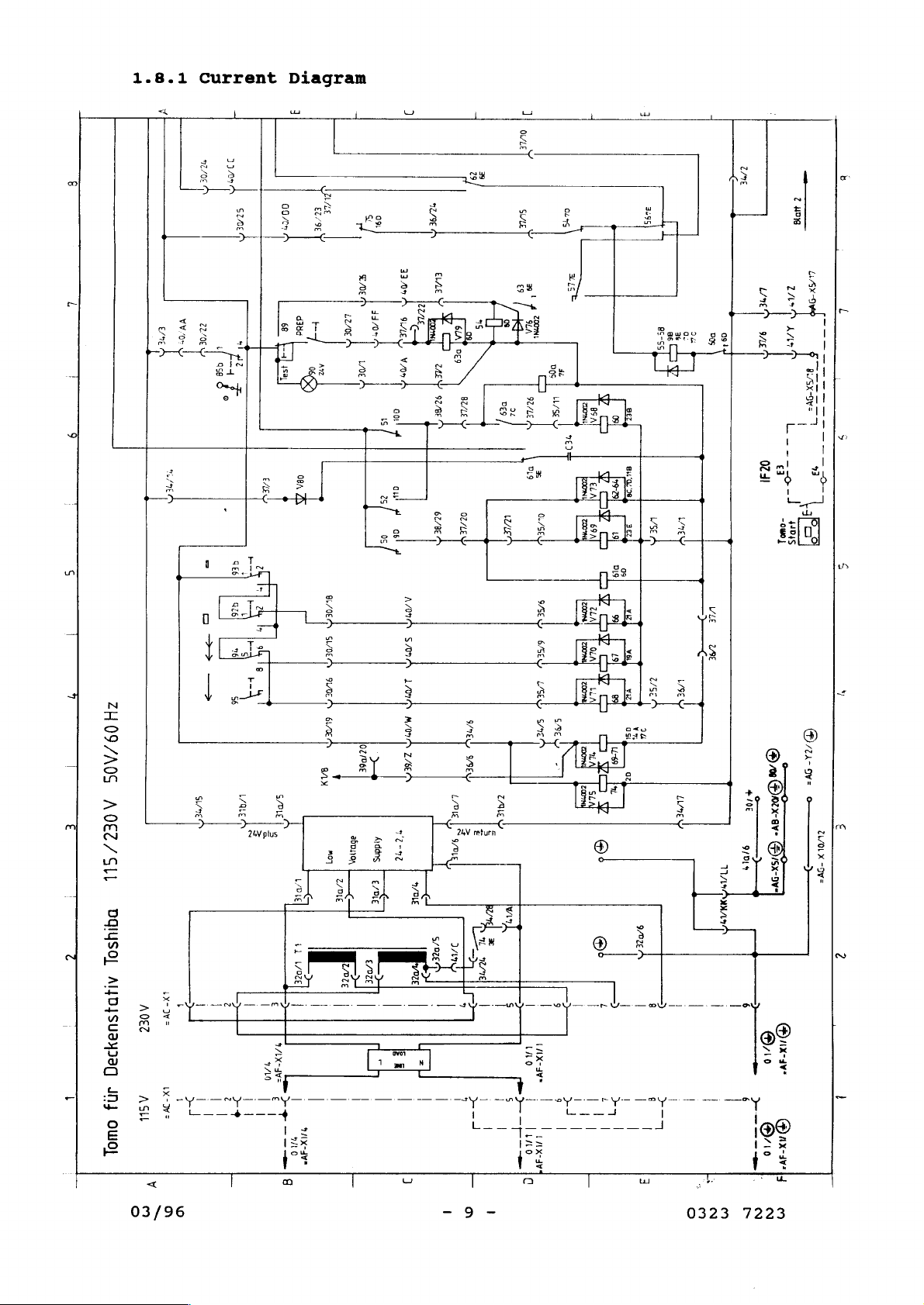
1.8.1
Current
Diagram
<
|
ZLI
vuo
ae
mek
4
33/09
|
Ц
95
—
た
SZ/0E
Å
이
42
“ny
ZH0O9/A0S
A0€EZ/GSIL
DAIYSO]
AI4DJSUSYI9(
AOEZ
IN}
ASK
OWOL
у
SL/TE
A
AAA
Y
OY
|
i
L
OY
>
1
|
|
|
1
“ay
-
„te
À
Ξ
2
|
|
va
+4
ζ
||
|
|
|
=
00705
4
9384
se
halısı
08A
set,
1
voe]
il
108€]
TE
|
|
dy
ae
;
|
-一
avs
SO
一
|8
一
一
;
Peer
LE
a
ή
KEM
LUNE
上
|
LOE
me
au
02706
a5pno
FE
were
|
|
|
|
|
|
=
25
05
>
e
Ard
dns
|
E/DiE
©
D
Е
>
|
|
¡
/
sf
.
|
|
|
REA
sie
AA
LEA
any
moj
|
:
|
。
LISE
A
332%
ELZE
à
62/8E
AARÓN
SATA
АЧХ
МИА
ТЕ
vi
1/DLE
で
S/DZE
>
LE
!
|
ER
=
|
|
|
3
we
>
vel
|
|
MEG
SEN
L/0
e
v
ny
|
|
>
>
κα
ケー
|
$
Ema
ml
Ť
|
i
|
|
|
ZEY
wind
5
=
TT
Y
39
Dig
x
0./5€
θε
OE
LED
ote
|
|
(AO
UK
|
lino
LAK
la
59€
Y
-
9
|
|
RLS
4
—_
pen
|
ELA
и
|
69A
더
zooms!
LA
[zoom
OLA
[τοπ]
LL
=
coord
"L
[zoom
SL
©
o
L
|
i
i
|
|
|
|
--
BE
©
Bud
o
3
AE
9
미
09
9
YE
99
19
VEL
τς
89
as
uso]
αξ
[η
—
|
71
|
|
85755
95
-
GE
の
sc
za
VOZEM
>
8
|
テナー
8
|
イイ
|
|
3
sa
Si
МЕ
I
TTT]
i/$E
I
LUNEY
|
!
|
|
|
|
Li
“ol
DOS
WLE
2AE
|
|
une
|
i
|
LINED
E
0231
>
ζ
49518
ον
“|
AA
+
|
ps
L--
o
1
“buo?
JD
rave
O,
10
„©
@ax-avely
710
A
一
一
一
二
一
一
一
一
一
一
一
一
7
o-
РЕ
3
-
É
ZL/0LX
-Dy=
2
ь
03/96
0323
7223
Page 10
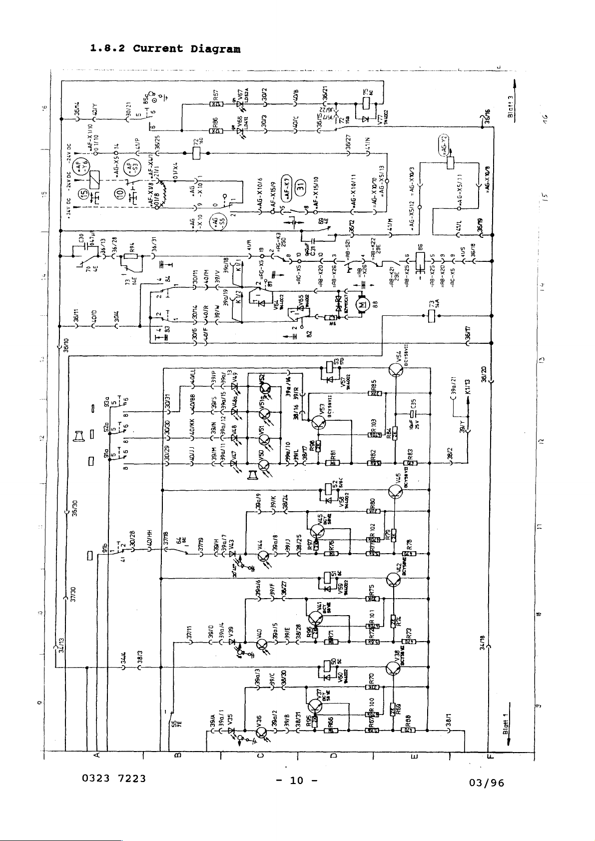
1.8.2
Current
Diagram
?U9E
3
Г
st
|
PH
т
Zerrin
=
στ
АК
[or
|
OL
36
0
1
^72-
65)
COE
29492-
|
©
DG
i
|
A7
|
não
063
37
0
PSE
0/07
|
01798
=
=
더
σα
I
DES
075
PIS
12706
5
817
53а
F-
8°
9
aj
SET
20Е
van
ESA
Z98
09
ZL
seu
A
ns
11507
A
EME
On
2079)
oo
|
(CA
DE)
SUSE
A
Е
НОВ
rampa
2v
(rav)
GE)
al
/
č
|
4/066
HSE
9L/8E
OL
mec
1/6E
OL/SLX-
Jv"
8
z|
DY
OCX-Bb=
ze
ESA
3%
“oes
=
E
ES
oy
4
ITARSAIG
.
an
tam
9/01
saca
X-9¥"
1
I
|
|
i
A
5
8
FA
S
・
8
3
S
|
8
ーー
LEDEM
EIDE
|
6204
|
Tw
]
da
al
OTA
|
[1/07
|
Pose
d76E
T
ЗОВ
SIE
Y
21
NEN,
DGE
Y
LL
HISEW
D6E:
GAR
A
M
ww
ong?
EL/5X-9V=
14/01X-9
OMOLX
LIOLX-Dys
-9V=
zzyーBB=
zs-
362
GZX-
시
y
σσ
28
sas
ML9
124788
|
EALX-OW=
TUSX-DV=
sy
sara
36z
massas
A
ョ
ビー
oAsax-aue
고
5
へ
ロ
ZX-
昌
=
vm
a
210€
|
((/5X-gV
>
SUSE
v
Βἰ/9ε
DET
sy
m-
gey
品
10
АЛЕ
RANA:
|
+
+
+
OZ/SE
P
at
m
pro
<
u
DEISE
НН?
9Z/OE
CU
916
L
σα
ーー
|
ELITE
T
06746
re
y
SULE
р
d
|
一
eee
=
ет
a
|)
|
39
oe
」
HÆE
İ
L10667
em
2
r=
À
<
~
LI
suUTE
ー
で
e
+
|
|
a
一
3
=
eia
J
,
5
un
LE
Q/6€
T
VIGE
Y
106€
SEA
11
sea
96E
B”
E
3
=
0323
7223
10
03/96
Page 11
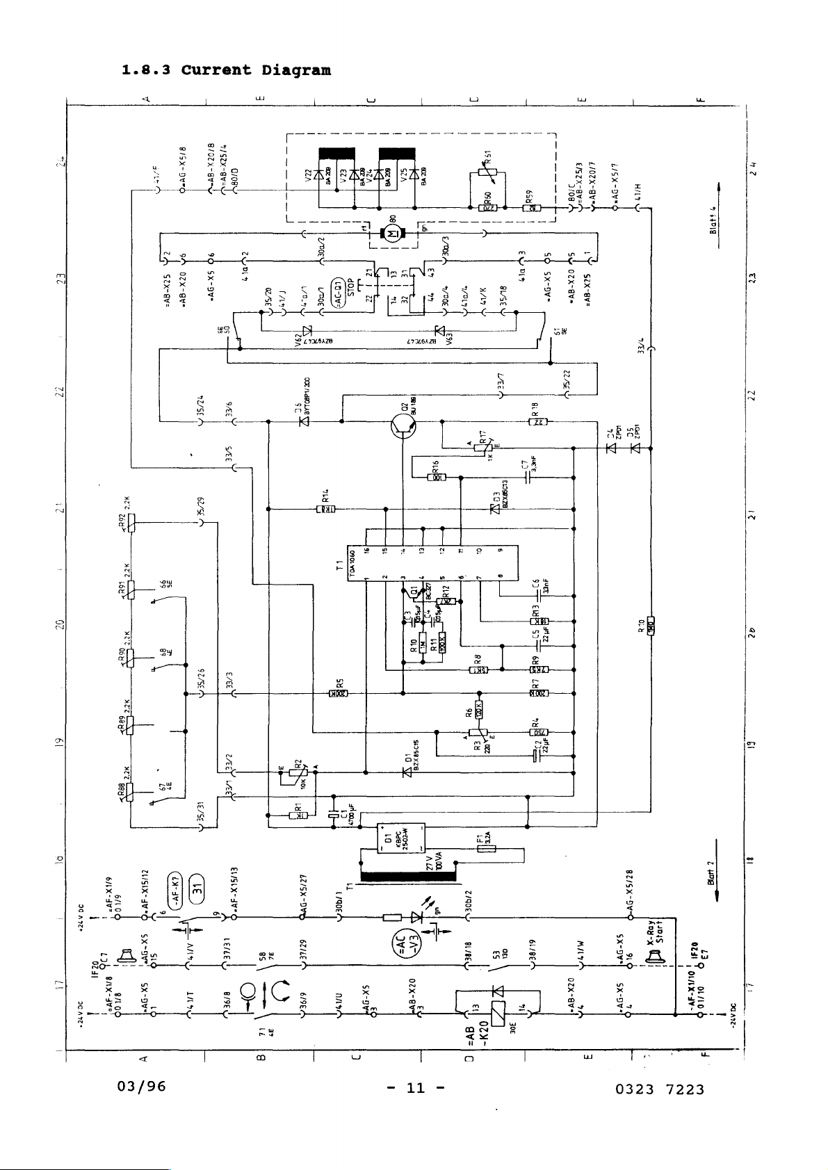
1.8.3
“2
зи
Current
B/02K-
8/5X-
avy
DW
ZÁ
EC
S7x-8v=
22
iz
9
6ἱ
!
9
ZU/SIX-4V*Ď
64x-307
610
LI
39
^лэё+
IAM
i
0231
|
|
Ч
Db
SUAVE,
ano
|
SX-DV5
|
σχ-ον"
9
$
【
90
94
|
Sx-Dv-
0ZX-8v
ッ
の
SE
-
(>)
CE)
7
Lan
ins
Diagram
|
|
also
0/08
aval,
PANA
IN)
Os
Εμ
we
on
|
ZA
|
|
|
レ
Ὕ
İzi
AS
SA
E
OC
/νάΡΟ1Λ8
9,
AE
SAL
E/EE
Y
LÆRT
A
可
LÆG
し
ESLX-
AVE
A
tele
BEL
O
9
85
36
LE
EM
3
O
ro
|
ig
ETISX-9
GTILE
6/96
9C
7
ny
i
09001
bd
Su
—
„ony
İM
u
1790
-
A
NAN
|
|
|
!
ンジ
Ls
st
ζ
ㅣ
Ly
。
348%
19
_
SX-DYA
εφ
|
|
|
Ve
5
À
ва,
eN
пе
CIR
「
z
“
와
29028
0
로
ーー
weosz
a
>
x
T
i
02x-evY
|
|
|
ESA
-
za
v
οι
4
£
eu
«
sx
나
EN
吃
we
id
27906
ФЕ
.
ει
02%-
gv-
=
|
|
VER
al
coy
ss
3
ες
-
£1058X
78
σει
|
30€
|
seyfi
aee
LT
|
927
emp)
or
вай
Lu
vali
12
6L/8€
ui
19
|
3υεε
azz
ala
E/SZX-8v=
470ZX-BV
-gy=
1
À
Γι
ay:
x
usem
|
+
|
MIS
о2х-ву*
9
21SX-9Y=
НИЯ
|
EE
で
1042
56
y
yy
TDK
이선
6775X-9V
J
Аоз-х
SX-DY*|
9%
1
UU)
σχ-ον”
9
44045
pl;
i
1
—
9
44018
一
—
7
—
ung
e
O24!
13
|
ounx-av-
01/10
DO
AT-
I
t
EL
72
tz
a?
fi
gl
L
|
03/96
11
0323 7223
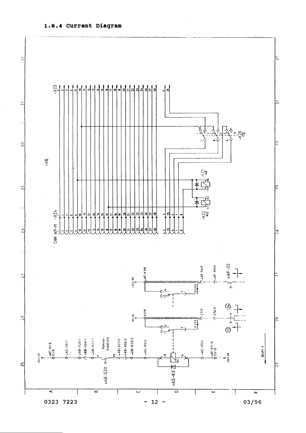
Page 12
ZE
と
1.8.4
i
Current Diagram
|
|
|
|
|
|
|
|
DE
6L
i
57
iz
-
、
1ZX-
W-dV
r
て
NN)
て
TS
>
se
ES
Er
πι
o>
ü
ws
a
μη
Et
E
。
ni
EC
>
το
6
ωδή
9”
u
“с
は
ας
>
위
>
区
ws
a
ui
EZ
EM
52
“>
οί
%
LT
>
awe
8
^
>
+
+“
M
SS
L
9
。
>
bs
9
ED:
LEN
ni
LA
Ora
i
N
Cx
|
|
s76X-』y*
レ
|
|
SS-dv=
-
|
1
(i
o
rv
6&
,
er
pe
c
52
LISX-9v*
sno
56
IC
AE
gnx-avr
|
0323
7223
07X-BY*
1/92x-8w=
Lay
M
“ua
5un1ddn
sos
©
02S-8v
Lavz
Z7LZX-V~
sm
ov
Ao
tIOTX-gv*
79ZX
-8Y=
6140
|
I
ZISX-D¥"
+)
ww
|
ει
-=
A
L
|------
a
2%
EX-DV=
ento
|
EXALO
975X-Y・
EDL
wy
!
|
|
017LX-JV*
oL/10
!
i
Gb
+i
上
十
T
€)
ao
Anz-
pot
po
03/96
Е
#018
Μου
oN
U
me
Page 13

1.8.5.Current
Diagram
of
D
igi
ital
Display
SA
JA
EA
60.
4095511
tt
Z€
Lg
60
411855
1Z
11
€
£
8
601
HU9sSI1
26,
8
NOIIVIIONI
IHOIFTH
YIAVI
TVLISIC
75080
JH
вом
De
Z/6E
StA
gro
eu
и
e
O
AISE
č
σι
a
ㅣ
зави
tA
8
9
oz
64
VOLA
UA
SAYRE
圖
ZİYA
Dm
AGE
ELA
03/96
13
0323
7223
Page 14

1.9
R1-3.3kQ
R3-6,82
R4-1,65kQ
R5-6.04kQ
R6-6,80
R7-6,80
R8-3,65kQ
R9-1kQ
R10-1.1kQ
R11-6,8k9
812-5009
R13-0,689
R14-0,680
R15-Brůcke
R16-3kQ
.Current
Diagram
of
Power
Supply
C1-470uF/35V
C3-220nF/1kV
C4-10pF/50V
C5-1000uF/63V
C6-1000uF/63V
C7-1000uF/63V
C8-1000uF/63V
C11-2204F
CR1-1N4002
CR4-1N4003
CR5-1N5401
CR6-1N5401
CR7-1N5401
CR8-1N5401
CR10-1N4002
CR12-1N4002
01-2N3055
02-P31823
U1-LM723CN
/63V
ζω
©
u
=
u
o
a
um
>
|CRS5
|CR7
F2i||32A(T1
16A(T)
nov
ADI.
(T)
Ri2-|Umit
220V0,8A
Condor,
0323
7223
D.C.Power
ー
14
Supply
-
HC.24-2,4A
03/96
Page 15

1.10
Physical
Location
of
Electrical
Components
(32)
(4)
(38)
03/96
7775
I5
-
ㆍ
0323
(37) (36)
(38)
(38)
(40)
7223
Page 16

1.10.1
Electric
Field
Installation
Diagram
ον
*
(Gi
BN
ne
bars
F1
3.2A
D1
0006
0248
a
0323
7223
hp
0322
-
16
0869
-
03/96
Page 17

1.10.2
ーー
IT
トト
HI
トト
トト
トト
Electric
E9A
-A
HI
Field
>
5
Installation
AF
OLA
LH
89A
—L
69A
LH
ILA
Diagram
©
©
E
9
x
る
2
5 = a
||
£
トト
トル
m
-=
A
111111111
Dal
раба
аа
|
LOI
hp
H+
ZLA
0322
0866
©
R94
=
аа
_
ŞE
[TITI
а
ва
Да
[а
[аа
03/96
69
hp
0322
70
0867
-
17
71
V74
-
72
75
H+
V77
0323
73
7223
Page 18

1.10.3
Electric
Field
Installation
Diagram
m
=
y
sE
に
Do
=
mm
し
ー
ΕΕ
|
|
[È
Я
T
62
55
Ap
63
56
0322
va
64
57
V78
0868
on
63a
54
V76
CT
V80
61a
58
NNW.
603
圖
—
na
E
—
上
m
53 52
Asl
©
9
hp
ASI
W
-BBC
0322 0865
一
一
AGI
⑯)
HE
51 50
一
6
RZ
一
ka
(e)
一
一
0323
7223
-
18
-
03/96
Page 19

1.10.4
ーー
一
ーー
=
=
Electric
Field
Installation
=
(eh
,
R10
|»
adL
val
Pr
Diagram
|
1131
|
IM,
pb
Ec
1441
EE
1451
|
86
+]
R7
O
ペグ
SS
0
=
*
‘E
=
hp
0322
Sa
0952
ο
и
|
M
AE
©
03/96
-
19-
0323
7223
Page 20

2.
INSTALLATION
2.1
Remove
Uncrating
shipping
2.2
Removal
Drive
Switch
Remove
screws
and
pull
the
strut
little
Remove
12,
and
packing
damage.
the
ET
plastic
with
bit,
screws
14).
ET
2000
up.
(Item
tilt
of
2000
power
4
mm
Remove
(Fig.
material.
Covers
of
maximum
off.
caps
(Fig.
wrench.
3).
it
to
Check
Swing cover
the
two
Lift
1,
the
up
front
Item
for
height.
1,
Item
screws
the
7 + 8)
completeness
1).
trim
and
pull
|
Loosen
(Item
(Item
cover
and
2)
4)
down.
(Fig.
two
to
and
(Item
2,
and
the
take
Item
upon
socket
front
out
5)
10,
a
2.3
Hold
insert
Attention:
The
border.
0323
Mounting
bracket
bracket
7223 -20-
the
of
Bracket
(Fig.
reinforcing
has
to be
2,
Fig.1
Item
strips
conclusive
8)
and
from
tighten
the
with
back
with
the
to
the
screws.
table
table,
frame
03/96
Page 21

03/96
Fig.
5
一 2 1-
0323
7223
Page 22

2.4
Tomo
Coupler
Installation
Install
screws
20).
Place
2.5
Place
8).
table
stiffening
(Item
thread
2.6
Fasten
26)
put
cables
is
and
fastener
plug
Mounting
Put
17).
rail
Mounting
with
cables
enough
fasten
the
(Item
with
fulcrum
through
frame
control
screws.
for
in
cable
space
cables
and
Bucky-Tomo-Coupler
21
+
22)
cables
of
Fulcrum
tower
cables
rail
plates
Fasten
(Item
of
then,
and
(Item
fulcrum
14).
Control
box
Remove
control
guide
for
on
lay
(Fig.
the
the
to
the
up
to
Tower
(Fig.
with plug
Bucky
13)
tower
Box
6,
cover
box
them
(Item
box
cables.
bottom
down.
the
3,
carriage
on
Item
(Item
(Fig.
carriage
plate
Item
of
of
both
with
29)
12)
(Item
25)
side
through
31).
Mount
the
5,
of
for
on
guide
sides
screws
to
table
wall
Check
cable
tube
Item
the
parts.
bracket
16)
between
rail.
under
(Item
(Item
bore-hole.
whether
box
side
18)
Bucky
frame
to
with
with
(Item
(Item
rear
Put
two
balance
15)
and
(Item
31)
and
Put
there
table
cable
Fig.
6
Fig.
7
0323
7223 -22-
03/96
Page 23

2.7
Mounting
of
Motor
Drive
Move
rail
temporarily.
in
(Item
sliding
36)
block
and
(Fig.
fasten
7,
column
Item
drive
35)
motor
in
cross
(Item
guide
34)
2.8
Mount
side
angle
to
ceiling
2.9
Insert
fixing
screw
fasten
2.10
Remove
Fasten
consideration
49)
over
Mounting
belt
to
ceiling
(Fig.
Tightening
drive
angle
(Fig.
finally.
Mounting
cover
tupe
of
the
the
flexible
of
fixing
9,
guide
belt
(Item
9,
of
from
coupler
ceiling
Fig.
Item
of
of
Drive
angle
guide
rail
Drive
(Fig.
49
Item
Tube
ceiling
the
tube
8
Motor
(Fig.
rail
43)
under
(Item
Belt
8
and
46).
Coupler
with
8
mm
column
to
8,
(Item
consideration
41).
und
Fig.
Item
Align
column
screws
space
(Item
ceiling
.
Item
41).
9,
Item
37)
and
column
(Fig.
(Fig.
to
axis
51).
column
Fig.
45)
Mount
tighten
drive
10,
of
Put
guide.
9
on
the
of
37)
11,
Item
rotation
connection
left-hand
belt
the
to
both
to
motor
Item
48)
fixing
tension
belt
fixing
and
53).
under
(Item
cable
03/96
-23-
|
0323
7223
Page 24

Main
2.10a
Remove
See
Mount
Philips
Remove
and two
plate,
unit
Mount
Remove
the
shafc
Modification
(Fig.
See
joint
the
support
lla).
bracket
plan head
the
and use
bracket
M4
(Fig.
the
and
two
resin
Fig.
x
10
C
after
screws.
M3
12
Philips
the
12)
D
after
connecting
of
arm
x
screws
cap
the
cover,
removing
8
Philips
removing
from
plate.
DST-100A
and
See
screws
(Fig.
to
standard
Support
brackets
bracket
11b)
screws
from
secure
bracket
See
(Fig.
Interlock
Spring
Fig.
B
from
the
solenoid
the
A.
support
12)
switch
T
11
Arm
A
and
B.
(with
the
interlock
See
arm
M4 x 12
Phillips
pao
head
screw
unit
a
DE
a
:
>
two
solenoid,
mounting
switch
(Fig.
and
.
12)
mount
Solenoid
、
M4
X
Rocacion
Magnec
lock
brake
pin
Brackec 8 Brackec
A
Cover
Fig.
0323 7223
lla
-24-
1
\
Ring,
E-cype
Brackec
Joint
x 8
Solenoid
Phillips
D
03/96
A
C
Fig.
Brackec
M3
11b
pan
mouncing
head
place
screw
Page 25

2.11
Mounting
of
Tomo-Interface
Mount
component
tomo-interface
plate
(Item
Fig.
12
angle
56).
(Fig.
Lo
12,
—
Item
ие
55)
to
electro
2.12
Mount
guide
electrical
Installation
drawer
rail
angle
unit
guide
(Fig.
of
Electrical
(Fig.
(Item
14,
57)
Item
13,
to
Unit
Item
back
61)
to
58)
wall
drawer
with
(Item
guide.
both
57).
cable
Insert
2.13
Disconnect
03/96
Insert
Fig.
Relais
plug-in
14
Board
connection
to
Ceiling
-25-
CNN
Fig.
Column
AP-M.
15
Fasten
0323
relais
7223
Page 26

board
0323
0710
to
ceiling
column
mechanically.
2.14
Cabeling
Attention:
Pay
attention
Part
Press cable
Plate
terminal
uncouple
line
plug
Ceiling
Put
relais
relais
of
to
grooved
drive
board
to
desription.
box
coupler
=AF-X1/8
01/X4.
plug
the
relais
(Fig.
and
the
(Item
Column
board
board)
ET
flexible
motor
in
(Fig.
beam
=AF-X1.
and
CNN
2000
board.
couple
Put
62)
=AG-X10.
to
tighten
(comes
(Fig.
AP-M
0323
to
6)
from
drive
cable
wiring
12)
to
Line
from
to
0710.
pin
to
ceiling
Place
tube
with
considering
in
tomo
diagram
relais
off
unsolvable
=AF-X1)
15)
plug-in
Put
plug
the
fulcrum
cable
to
relais
motor
plug
CNN
=AB-X25.
electric
!!!
=AF-X15
=AF-X1
connexion
new
AP-M.
column
from
board
drive
the
tower
and
(comes
with plug
and
tighten
plug
(coming
Place
and
connect
the
tube
and
starting
Then
colour
(Fig.
(Item
clamp
from
01/X3.
unsolvable
=AB-X23
connection
plug
coupler
couble
connect
as
well
14)
cable
61)
cable
to
=AF-X9)
Uncouple
of
from
over
for
to
each
control
screw
the
the
cable
=AB-X5
the
motor
relais
line
as
the
tomo
to
2.15
Mount
Dismount
cable
support.
Attention:
stand
Range
from
of
New
Cable
cable
The
grooved
the
opposite.
movement:
support
-70°
TOMO
TOMO
Support
(Fig.
flexible
-
+125°
11,
Item
tube
has
respectively
71)
to
and
mount
mounted
-125°
-
to
+70°
new
wall
0323 7223
Fig.
16
—26-
03/96
Page 27

2.16
Installation
of
Tomo
Marks
Bring
with
and
column
3.
3.1
Remove
74).
radiation
pencil.
install
(Item
Adjustment
Adjustment
front
Move
Tomo
81).
of
panel
unit
radiation
mark
Fulcrum
(Fig.
up
to
(Fig.
to
25,
100
unit
16,
Film
Item
cm
some
Item
Plane
73)
SID.
and
Mark
cm to
80)
rear
on
the
to
cover
telescope
foot side
telescope
(Item
Place
ble
top.
Measure
plane
ling
ruler
(Fig.
bar
the
to
Fig.25
(Fig.
distance
27,
the
26,
Item
distance measured
Item
between
78).
76)
across
lower
Adjust
(Fig.
the
Fig.
profile
edge
fulcrum
28).
26
of
rails
ruler
of
and
the
of
film
coup-
ta-
03/96
'
-27-
0323
7223
Page 28

3.2.
Remove
(Fig.
Push
The
equal
potentiometer
height
table
Note:
Proper
procedure
29,
Setting
front
26,
button
distance
the
to
top.
adjustment
Item
of
Layer
cover
Item
until
between
distance
(Fig.
24
cm
Set
pot
must
84 + 85)
Fig.27
(Fig.
76)
layer
between
distance
(Item
requires
be
repeated
are
Height
across
upper
29,
interactive.
25,
profile
height
table
ruler
Item
between
85)
to
a
Item
and
84)
"24
10
minute
several
Fig.
73
rails
is
level
edge
fulcrum
to
fulcrum
cm",
times,
28
+
and
"O
and
warm-up
75).
of
with
(Item
cm".
the
Place
table
table
ruler
Drive
upper
period.
pots
must
77).
edge
ruler
top.
top.
be
Set
layer
of
The
(Fig.
0323
7223
-28-
03/96
Page 29

Fig.29
3.3
Open
gnetic
cycles
24
12
9
Timing
clamp
'
clutch.
for
cm.p.s
cm.p.s.30
cm.p.s.22,5.r.p.m.at
60
of
(Fig.
60
r.p.m.
r.p.m.
Exposure
15,
Mark
seconds.
the
at
at
Cycles
Item
12
12
12
58)
clutch.
cm
layer
cm
layer
cm
layer
to
Push
interrupt
TEST
height,
height,
height,
function
button
40°
20°
Zono
and
<<,
2,2
< , 2,2
1,2
sec.
of
count
sec.
sec.
ma-
09/95
Fig.30
-29-
0323
7223
Page 30

In
case
of
deviations,
adjust
with
pots:
Fig.
3.4
Remove
Item
The
carriage.
(Item
30,
Switch
cover
91)
switch
93)
Item
Item
Item
by
Adjust,
and
87
88
89
flap
of
hand
flap
turn
(R
88)
(R
90)
(R
91)
TOMO
and
should
if
lever
fast
slow
Zono
coupling.
move
necessary.
not
(Item
speed
speed
speed
the
touch
Actuate
bucky
Therefore
94).
the
in
edge
solenoid
coupling
of
loosen
(Fig.
position.
the
sliding
31,
screws
Fig.31
0323
7223
-30-
09/95
Page 31

4.
TECHNICAL
MAINTENANCE
4.1
Note:
The
out
power,
Defective
acc.
Use
Do
Preperation
Switch
Mechanical
maintenance
at
switch
to
only
not
grease
off
12month
parts
spare
non-acid
equipment.
and
schedule
intervals.
off
must
parts
or
oil
Electrical
power
be
list.
grease
ball
Tests
described
If
functional
immediately
replaced
for
maintenance.
bearings
below
afterwards.
by
genuine
with
sealing
must
tests
be
carried
require
spare
washers.
parts
Remove
Fig.32
covers
(Fig.
32,
Item
B-F
and
73 - 75).
09/95
-31-
0323
7223
Page 32

Tube
Check
Check
Adjust
Check
sition.
Check
Coupling
Check
Coupler:
screws
on
smooth
with
compression
magnet
mechanism
and
and
set
to
replace,
tighten,
operation
screw,
spring
hold
coupler
must
if
if
necessary.
and
if
necessary.
to
in
have
no
necessary.
play.
pull
park
play.
coupler
position.
in
park
po-
Fulcrum
Check
Limit
Check
Check
Adjust
Check
Clean
slide
Check
Check
ce,
Digital
Layer
cessary,
Tomo
Check
Operate
Flap
Check
Check
Support:
and
switches
and
spindle
or
belt
coupling
rail
fulcrum
electrical
if
necessary.
Display:
height
Coupler:
and
magnet
must
and
microswitch
tighten
adjust,
drive
replace,
drive
and
on
must
readjust
tighten
not
be
readjust,
screws,
must
contact
if
on
if
on
tension.
bar
carriage
fulcrum.
film
connections
coincide
acc.
screws,
by
hand
too
if
actuation.
if
in
necessary.
play
and
necessary.
plane
and
with
3.2.
if
and
couple
high
and
necessary.
necessary.
end
positions.
grease
Adjust
(film
and
if
plane).
adjust,
cables
height
necessary.
flap
should
lightly.
necessary.
if
on
indicated.
with
couple
Lightly
necessary.
damage.
bar
carriage.
without
grease
Repla-
If
ne-
play.
Electrical
Check
ce,
if
Check
sary.
Check
Control
Check
necessary.
Check
Check
0323
7223
Unit:
electrical
necessary.
and
tighten
all
parts
Box:
and
tighten
friction
functioning
connections
mechanical
on
firmness.
mechanical
of
swing
of
all
and
controls
-32-
and
cables
fastening
Tighten,
fastening
readjust,
and
on
damage.
devices,
if
necessary.
to
table
if
buttons.
Repla-
if
neces-
frame,
necessary.
09/95
if
Page 33

4.2.
Functional
Tests
Tube
-
-
Coupler:
Folding
Remaining
up
spring, magnet)
-
Locking
Fulcrum
-
Layer
-
Coupling
Digital
-
Display
-
No
Tomo
-
Coupling
~
Not
indication
Coupler:
the
Support:
height
Display:
correct?
bumping
and
in
coupling
drive
bar
remaining
without
against
down
park
jumps?
play?
smoothly?
position
bar
running
in
sledge
Without
without
without
center
edges?
play?
accurately?
play?
noise?
position
(Recuperating
accurately?
Electrical
-
All
electrical
-
All
connections
Control
-
Swing
-
All
buttons
Unit:
Box:
having
cables
correct
friction
switching
without
and
tight?
in
any
position?
accurately?
damage?
09/95
-33-
0323
7223
Page 34

4.3
SPARE
Ansicht
B
PARTS
4
に
RETA
14
-
24
25
Sl
|
$
NE
21
mo
=
à
T
Ansicht
A
0323
7223
Page 35

4.3.1
Part
SPARE
Names
PARTS
/
Ordering
LIST
Numbers
Failed
as
listed
serial
change
selves
See
also
REF.No.
1
2
3
4
48
5
6
7
8
9
10
11
12
13
14
15
16
17
18
19
20
21
22
23
24
25
26
27
27a
28
29
30
31
32
33
34
35
36
37
38
39
40
spare
parts
below.
number
of
parts
or
by
qualified
chapter:
Name
Frame
Harness
Transformer
Control
P.C.
Frame
Board,
Supporting
Circuit
Circuit
Circuit
Circuit
Amplifying
Drawer
Angle
Nut
Belt
Tomo-interface
Bracket
Belt
Return
Bracket
Mounting
Coupling
Gear
Drive
Motor
Tomo
Tube
Magnet
Compression
Bolt
guide
for
clamp
pulley
wheel
system
mark
coupler
board
board
board
board
T-notch
Compression
Strap
Coupling
bar
When
of
unit
or
"Safety
variable
part
board
plate
bracket
complete
spring
spring
may
be
ordering
and
elements
personnel
replaced
complete
may
Notes".
」
only
spare
only
being
with
parts
number
be
carried
authorized
original
always
of
part.
parts
indicate
The
out
by
to do
Part
0322
0322
0622
0006
0006
0006
0006
0322
0322
No.
0910
1070
0651
0248a
0248b
0213
0214a
0869
0866
0322 0867
0322
0322
0005
0323
0323 0654
0323 0663
0323
0323 0682
0660
0323
0323
0323
0006
0322
0323
0006
0322
0323
0005
0005
0322 0733
0005
0322
0868
0865
0158f
0335
0706
0877
0648
0651
0644
0478
0754a
0642
0195a
0786
0590
0094
0040a
0042p
0736
0322 0627
ex-
our-
so.
09/95
-
35
-
0323
7223
Page 36

REF.
41
42
43
44
45
46
47
48
49
50
51
52
53
54
55
56
57
58
59
60
61
62
63
64
65
66
67
68
69
70
71
72
73
74
75
76
77
78
79
80
81
82
83
84
85
86
87
88
89
90
91
92
93
94
95
96
97
No.
Name
Gearmotor
Toothed
Toothed
Switching
Switch
'
Circuit
Switch
Reflector
Reflector
Acme
thread
Bridge
Lifting
10-speed
Gear
Gear
Pinion
Switch
Driver
Carriage
Catch
Spring
Bridge
Clamp
Spacer
Cable
Rear
Top
Front
Dry
cover
cover
cover
rot
Switch
Control
Switch
Cable
Bulb
Bucky
tomo
Switch
Solenoid
Cable
Extension
Magnet
Coupling
belt
belt
wheel
bar
board
(on
-
(on)
nut
spindle
potentiometer
complete
key
element
part
complete
board
coupler
cover
plate
off)
Part
0322
0322
0005
0322
0006
0322
0322
0322
0322
0322
0322
0322
0006
0322
0322
0322
0322
0322
0322
0322
0322
0322
0322
0322
0323
0323
0323
0323
0006
0322
0323
0322
0323
3360
0323
0006
0006
0323
0322
0322
0322
No.
0528
0530
0116
0586
0079a
0952
0875
0588a
0588b
0526
0534
0522
02518
0971
0968
0960
0569
0572
0558
0566
0567
0608
0616
0615
0435
0318
0320
0317
0260
0816
0444
0909
0453
0001
0580
0079a
0245
0582
0674
0672
0642
0323
7223
-
36
-
09/95
Page 37

4.4
Inspection/Maintenance
Certification
Inspection/Maintenance
the
maintenance
quired,
parts
Replacements:
9 ο 9 ㄴ … 5 ο ο
Date
defective
as
listed
οσο
(Give
©
0 0
è 0
Service
has
instructions
parts
have
below:
Item-No.
0 0 0 o
2..
0 0 0 o © 0 0 0 0 0 ο ο 0
Company
been
of
the
been
only)
(Stamp)
carried
manufacturer.
replaced
0»
ο
9 9 9 5
Signature
out
by
according
Where
genuine
EE
LE
to
re-
spare
ο ο .
Subject
Hans
09/95
Pausch
to
technical
alterations.
Rôntgengerätebau
D-91056
Erlangen
Graf-Zeppelin-StraBe
ー37ー 0323
TV/Ru
Germany
1
7223
 Loading...