

Page 1
Service Manual for L1 and L2
Nokia Lumia 1520
RM-937, RM-938,
RM-939, RM-940 (AT&T)
Key features
5.98" ClearBlack display
2GB RAM
32 GB Internal mass memory (16 GB AT&T)
20 MP camera
Wireless charging
Version 1.0
Check the repair
policy before
performing any
mechanical repair
on Service Level
1&2!
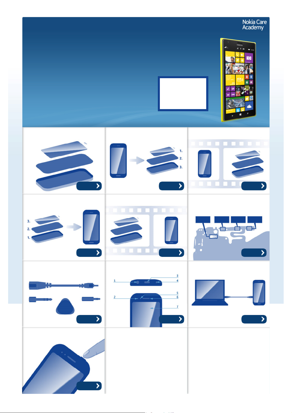
Exploded view Disassembly steps Disassembly video
More More More
Assembly steps Assembly video Solder components
More More More
Service devices Product controls and interfaces Service concept
More More More
Phone reset
More
©2013 Nokia | Nokia Internal Use only | All Rights Reserved.
Page 2
Service Manual Level 1 and 2
Nokia Lumia 1520
RM-937, RM-938, RM-939, RM-940 (AT&T)
Version 1.0
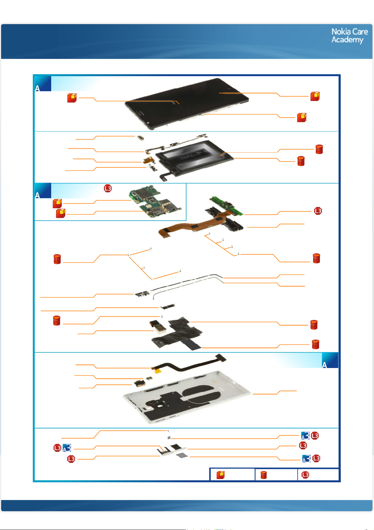
DISPLAY ASSEMBLY
(I0001 - I0003)
1
LIGHT SWAP PACKAGE
(I0013 - I0015)
3
DISPLAY
I0003
EARPIECE
I0009
SIDE KEY FLEX
I0005
VIBRA FLEX
I0004
VIBRA SUPPORT
I0022
LIGHT SWAP PWB
I0014
SKYPE CAMERA
I0013
Exploded view
TOUCH WINDOW
I0001
CHASSIS
I0002
BATTERY ADHESIVE
I0007
BATTERY
I0006
BOTTOM MODULE
0017
IHF ANTENNA
I0016
SCREW TORX+
SIZE 4 M1.2 X 2.6
I0024
DISPLAY CONNECTOR SUPPORT
BRIDGE CONNECTOR SUPPORT
*Only in AT&T
variant RM-940
I0021
I0023
SCREW TORX+
SIZE 4 M1.2 X 2.6
I0024
CAMERA
I0020
PMA FLEX
I0028
LED FLASH
I0011
AV FLEX
I0012
SCREW TORX+
SIZE 2 M1.4 x 2.0
I0025
TYPE LABEL
I0015
SD TRAY
I0027
Only available
as assembly
SCREW TORX+
SIZE 4 M1.2 X 2.6
I0024
COAX CABLE 2
I0019
COAX CABLE 1
I0018
HEAT SPREADER
I0008
SHOCK ADHESIVE
I0029
UNIBODY MODULE
(I0010 - I0012, I0028*)
UNIBODY
I0010
IMEI LABEL
I0015
SIM TRAY
I0026
TYPE LABEL
I0015
Not reuseable
after removal
2
Repair/swap
only in level 3
©2013 Nokia | Nokia Internal Use only | All Rights Reserved.
Page 3
Service Manual Level 1 and 2
Nokia Lumia 1520
RM- 937, RM-938, RM-939, RM- 940 (AT&T)
Version 1.0
Disassembly steps
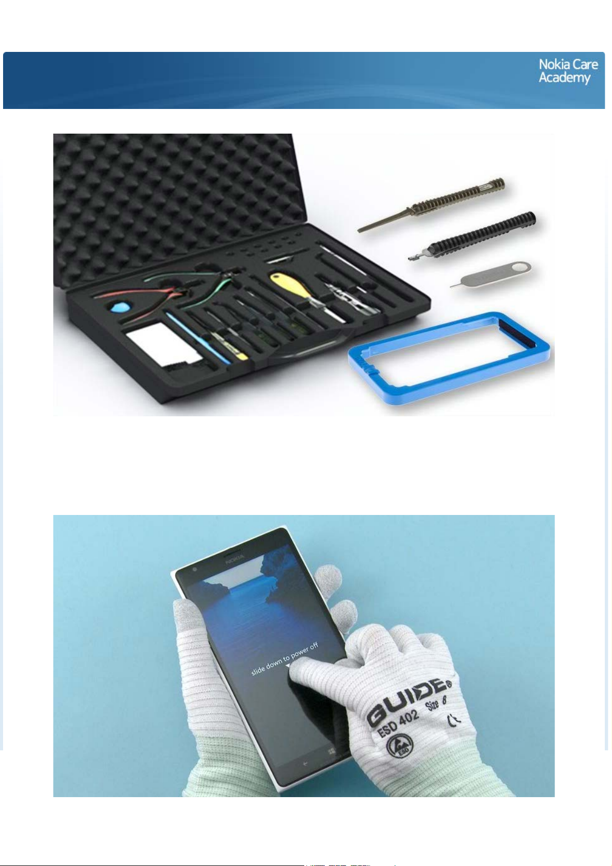
1) For disassembling you need the Nokia Standard toolkit version 2. You will also need the SIM door key,
the unibody opening frame SS-321, the RF cable disassembly/assembly tool SS-298 and the battery
release tool SS-317.
Note that the device used in this disassembly procedure is RM-940.
2) The power must be off during the disassembly procedure.
Page 4
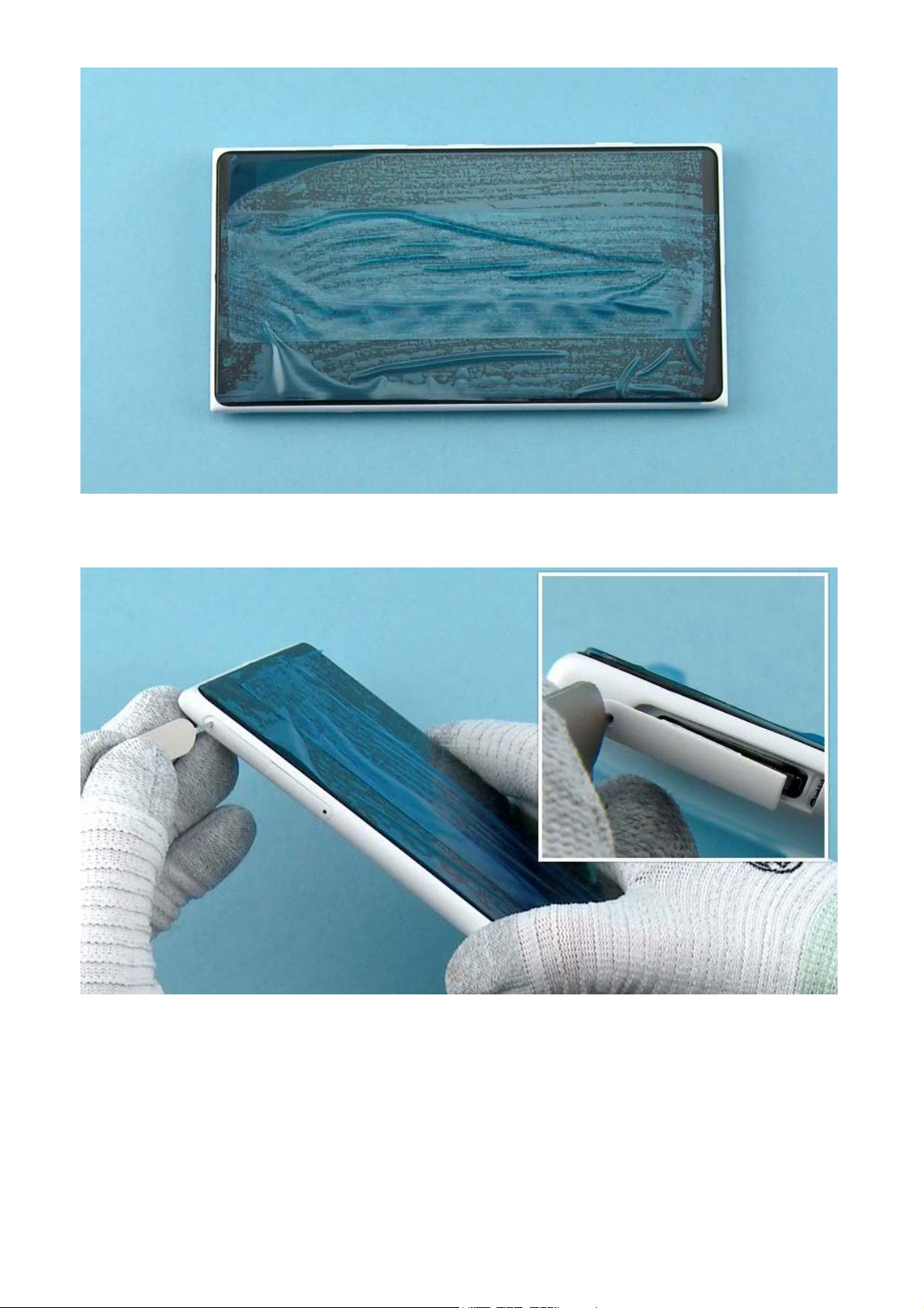
3) Protect the DISPLAY with protective film.
4) Release the SD TRAY with the SIM door key and pull the tray out.
Page 5
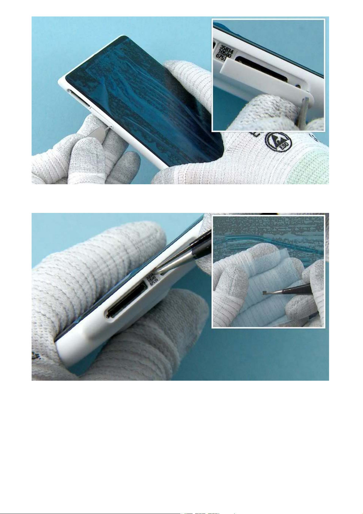
5) Release the SIM TRAY with the SIM door key and pull the tray out.
6) Use tweezers to remove the IMEI LABEL. Store the IMEI LABEL on non-stick surface so it can be reassembled.
Page 6
7) Unscrew the TORX+ size 2 LOCKING RAIL SCREW.
8) Use the unibody opening frame SS-321 to separate the DISPLAY ASSEMBLY and the UNIBODY
ASSEMBLY. First place the bottom end of the device into the frame.
Page 7
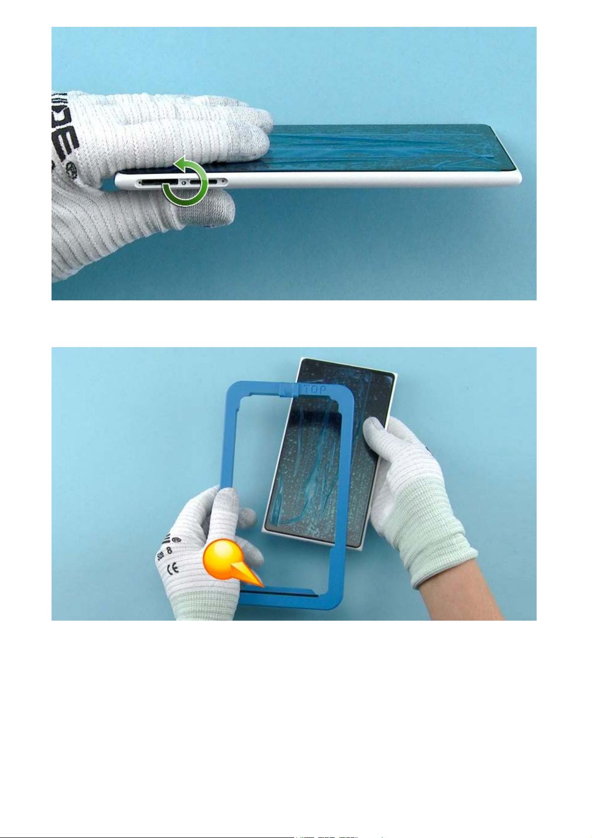
9) Place the top end of the device into the frame.
10) Start releasing the DISPLAY by pressing the device upper end from back side. Press both sides so
that the top end of the DISPLAY lifts up from UNIBODY ASSEMBLY.
Page 8
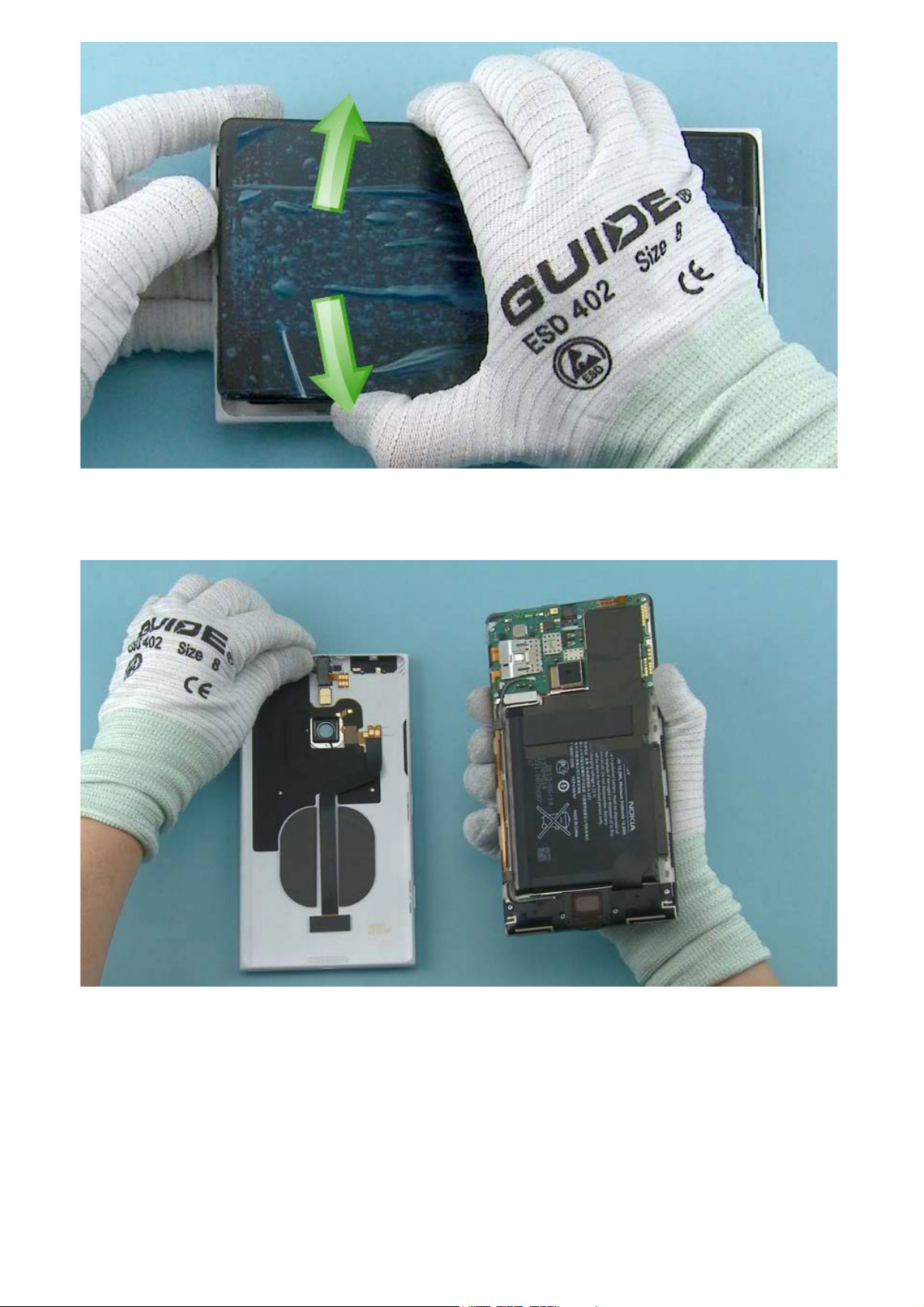
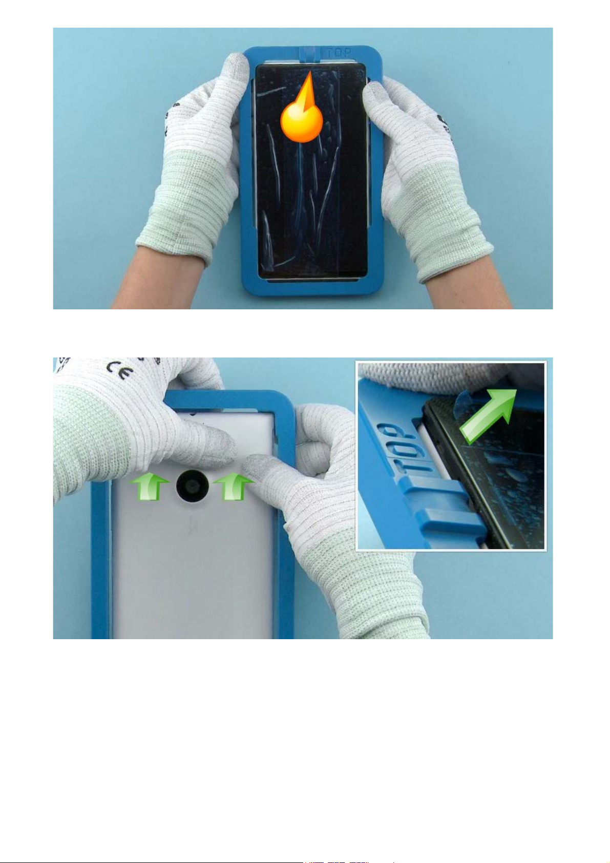
11) Remove the unibody opening frame SS-321 and continue separating the DISPLAY by moving the
UNIBODY ASSEMBLY carefully from side to side with hands.
12) The DISPLAY and the UNIBODY ASSEMBLY can now be separated.
Page 9
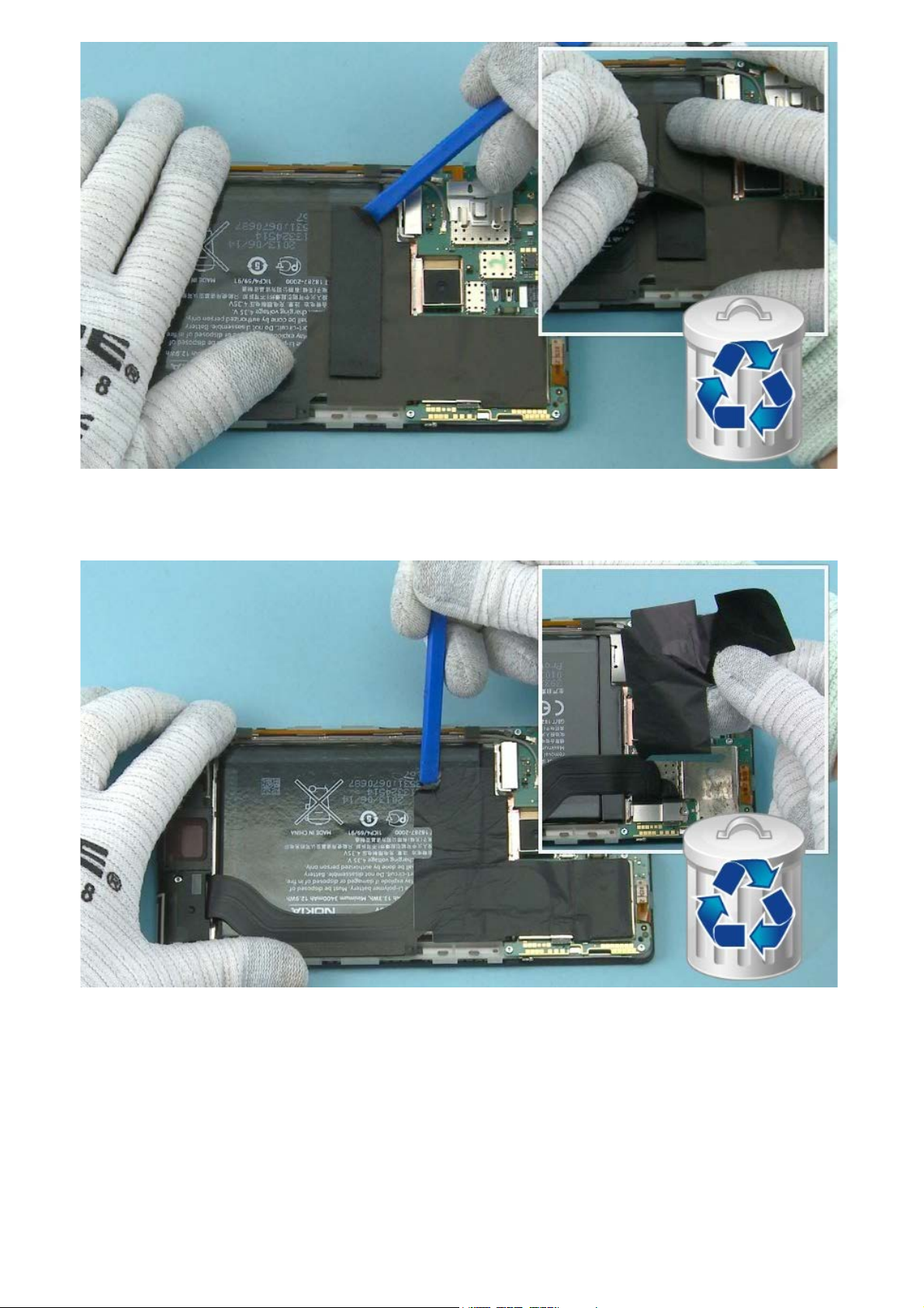
13) Use the SS-93 to detach one corner of the SHOCK ADHESIVE and then peel it off with fingers. Do not
use it again. Discard it.
14) Use the SS-93 to detach one corner of the HEAT SPREADER then peel it off with fingers. Do not use
it again. Discard it.
Do not damage the battery surface. Be careful not to leave residues from HEAT SPREADER around the
battery connector as it may cause shortcircuit. If adhesive residues are left on MSM shield lid, remove
them with isopropyl alcohol.
Page 10
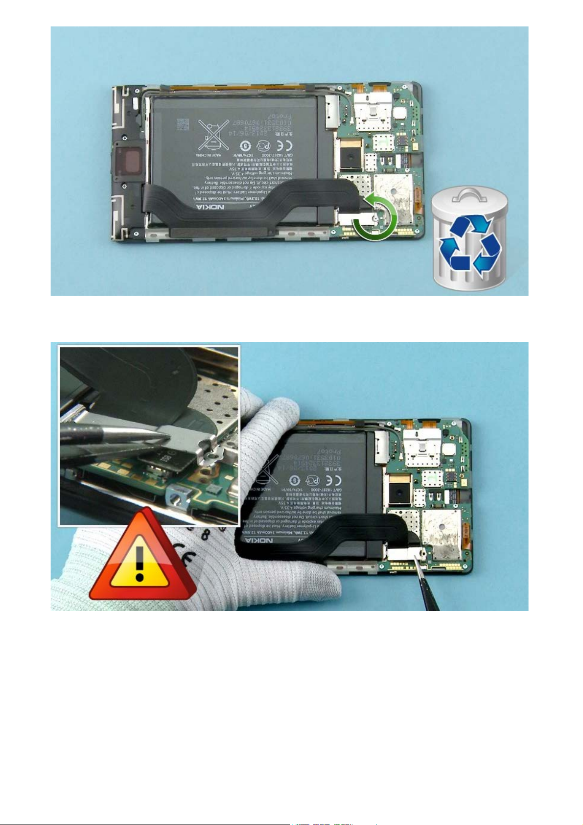
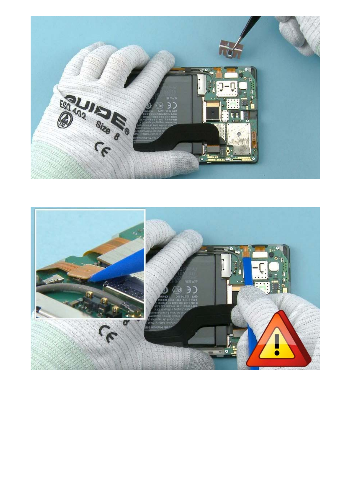
15) Unscrew this TORX+ size 4 screw. Do not use it again. Discard it.
16) Detach the BRIDGE CONNECTOR SUPPORT with tweezers.
Be careful not to damage the connectors underneath or any nearby components.
Page 11
17) Use the SS-93 to open the BATTERY CONNECTOR.
Be careful not to damage the connector or any nearby components.
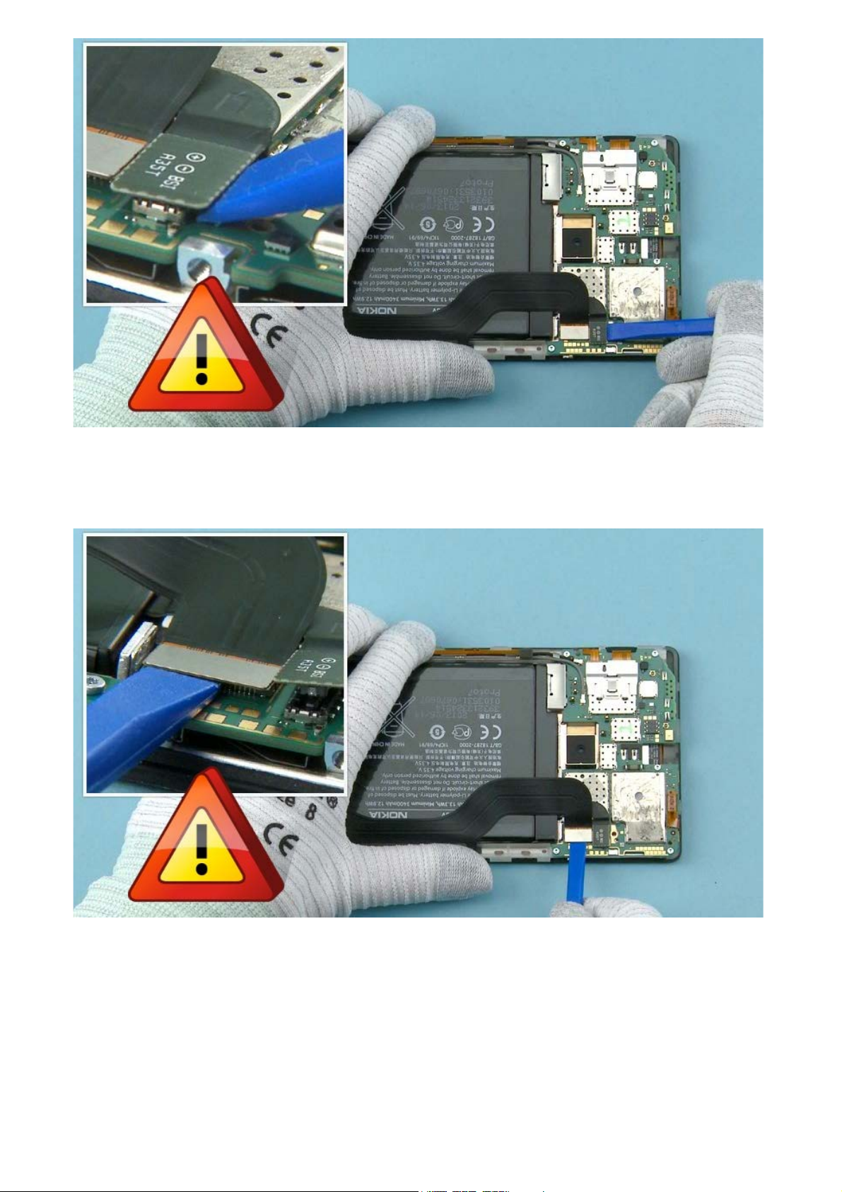
18) Use the SS-93 to open the BRIDGE CONNECTOR.
Be careful not to damage the connector or any nearby components.
Page 12
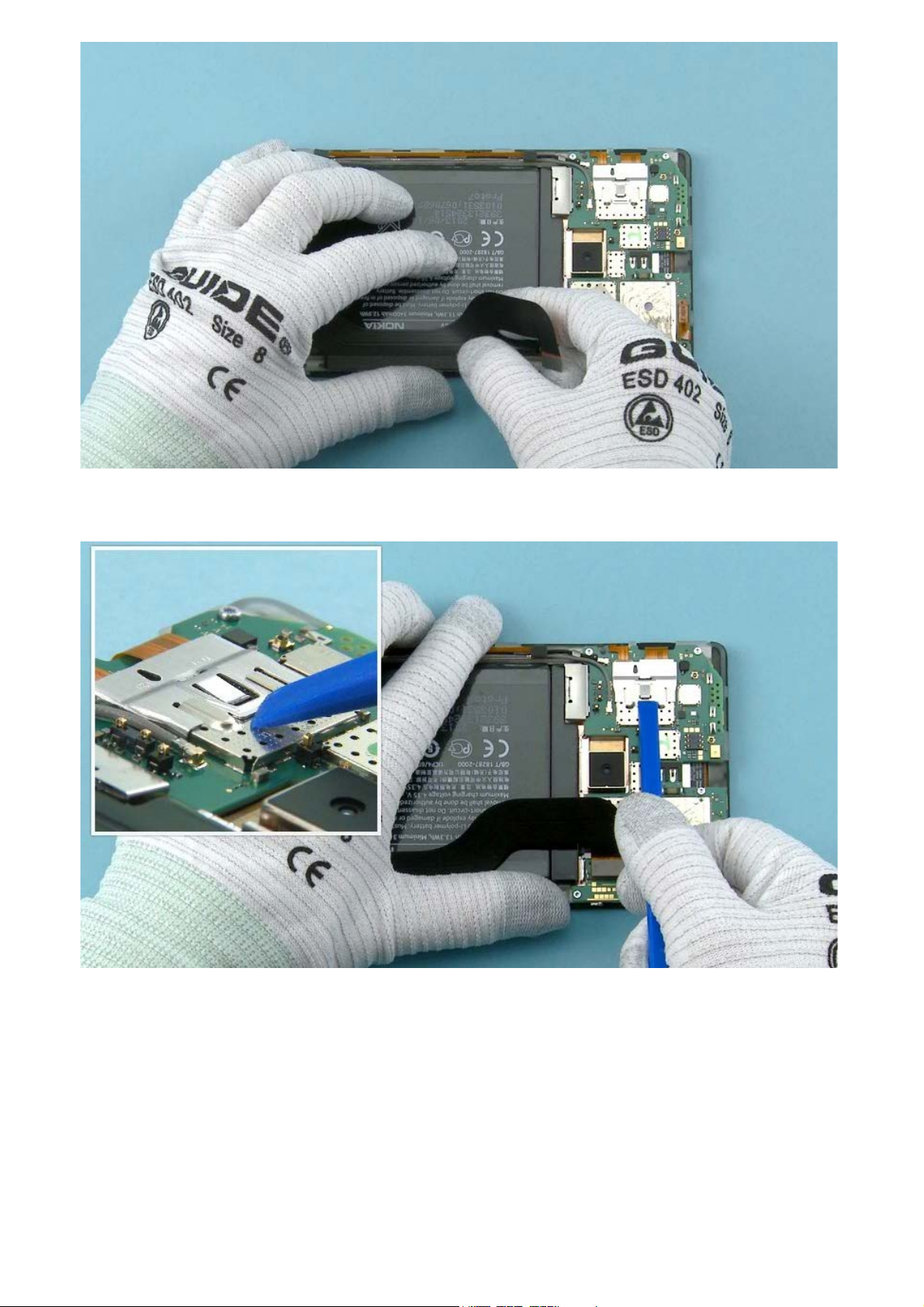
19) Detach the BRIDGE FLEX from the BATTERY with fingers.
20) Use the SS-93 to release the DISPLAY CONNECTOR SUPPORT.
Page 13
21) Remove the DISPLAY CONNECTOR SUPPORT with tweezers.
22) Use the SS-93 to open the SIDE KEY FLEX CONNECTOR.
Be careful not to damage the connector or any nearby components.
Page 14
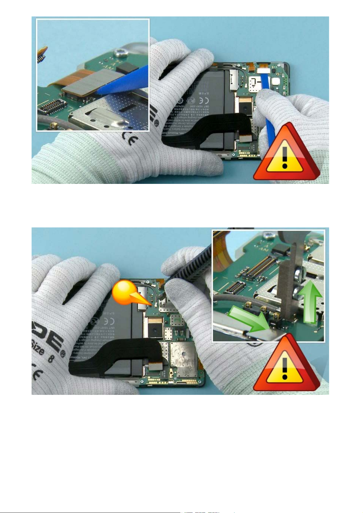
23) Use the SS-93 to open the DISPLAY CONNECTOR.
Be careful not to damage the connector or any nearby components.
24) Disconnect this RF CABLE with the SS-298. Lock the SS-298 to the top of the connector as shown
and lift it up carefully.
Be careful not to damage the connector or any nearby components.
Page 15
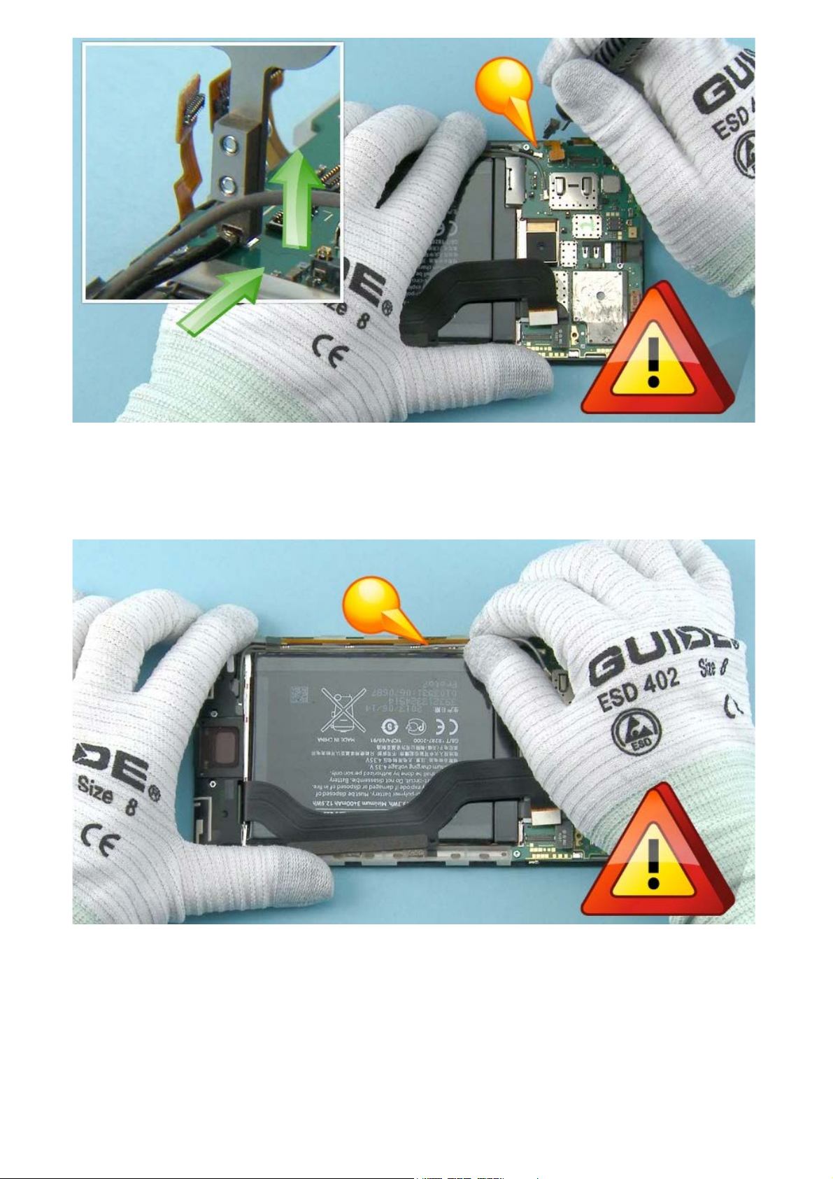
25) Also disconnect the second RF CABLE with the SS-298. Lock the SS-298 to the top of the connector
as shown and lift it up carefully.
Be careful not to damage the connector or any nearby components.
26) Lift the first RF CABLE carefully from the cavity with fingers.
Do not use tweezers or sharp tools as those may damage the cable.
Page 16
27) Lift the second RF CABLE carefully from the cavity with fingers.
Do not use tweezers or sharp tools as those may damage the cable.
28) Unscrew the four TORX+ size 4 screws. Do not use them again. Discard them.
Page 17
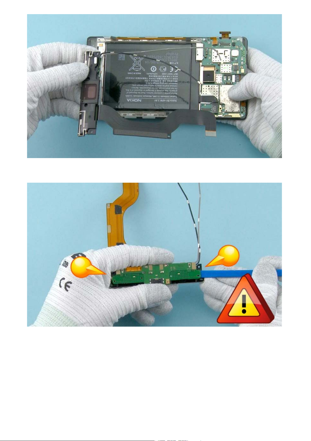
29) Separate the IHF ASSEMBLY.
30) Use the SS-93 to carefully detach the BOTTOM MODULE from the IHF ANTENNA. Lever the BOTTOM
MODULE from both ends to loosen the adhesive.
Be careful not to damage the components underneath the BOTTOM MODULE.
Page 18
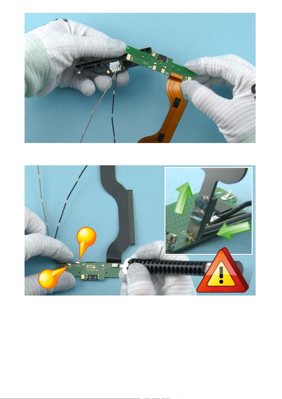
31) The BOTTOM MODULE and the IHF ANTENNA can now be separated.
32) Disconnect the RF CABLEs with the SS-298. Lock the SS-298 to the top of the connectors as shown
and lift it up carefully.
Be careful not to damage the connectors or any nearby components.
Page 19

33) Unscrew the five TORX+ size 4 screws. Do not use them again. Discard them.
34) Lift the ENGINE BOARD. Use the SS-93 if needed.
Be careful not to damage the components underneath the ENGINE BOARD.
Page 20

35) Use the SS-93 to open the CAMERA CONNECTOR.
Be careful not to damage the connector or any nearby components.
36) Remove the CAMERA with tweezers.
Page 21

37) Use tweezers to remove the VIBRA SUPPORT.
38) Use the SS-93 to release the VIBRA. Remove the VIBRA with tweezers.
Page 22

39) Use tweezers to remove the EARPIECE.
40) Release the straight part of the SIDE KEY FLEX by sliding the SS-93 as shown.
Page 23

41) Detach the SIDE KEY FLEX by pulling it with tweezers as shown.
42) Remove the SIDE KEY FLEX.
Page 24

BATTERY REMOVAL IF OLD VERSION OF THE BATTERY ADHESIVE IS IN USE
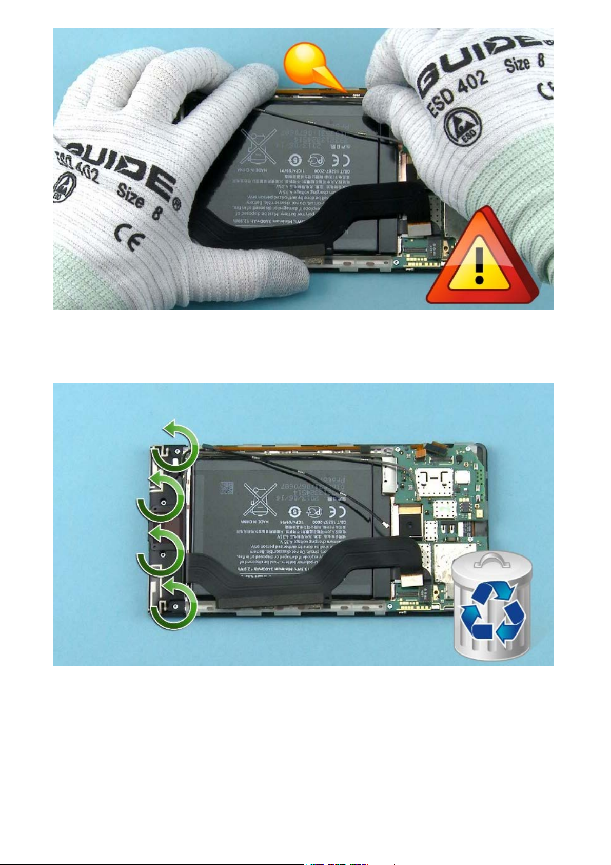
43) Insert the SS-317 into the shown place between the BATTERY and the CHASSIS. Push the SS-317
slowly and steadily forward to loosen the adhesive. Do the same on the other side of the battery.
Be careful not to damage battery or battery surface as it may cause leak or short circuit.
44) Continue loosen the adhesive carefully from side to side untill the BATTERY can be removed with
hands.
Do not reuse the battery after disassembly.
Page 25

BATTERY REMOVAL IF NEW VERSION OF THE BATTERY ADHESIVE IS IN USE
45) Pull the adhesive tape carefully with pliers from battery corner. When tape has come out a bit, move
pliers to get a better grip, or continue pulling it with fingers.
46) Pull one tape out first, then pull the another one out.
Page 26

47) Remove the BATTERY.
Battery can be re-used if no physical damages seen after removal.
48) Use the SS-93 to lift the FLASH. Remove it with tweezers.
Page 27

49) Place the SS-93 between the AV ASSEMBLY and the UNIBODY. Lever the AV ASSEMBLY out from its
cavity.
50) Pull the AV CONNECTOR up with fingers and release the contact pad with the SS-93.
Page 28

51) Use the SS-93 to release the top end of the PMA FLEX . Release the other end of the PMA FLEX by
pushing the contacts with the sharp end of the SS-93.
NOTE: PMA FLEX can be disassembled only in AT&T variant, RM-940.
52) Separate the PMA FLEX.
Page 29

53) The Nokia Lumia 1520 disassembly procedure is complete.
-END OF DISASSEMBLY-
©2013 Nokia | Nokia Internal Use only | All Rights Reserved.
Page 30

Service Manual Level 1 and 2
Nokia Lumia 1520
RM- 937, RM-938, RM-939, RM- 940 (AT&T)
Version 1.0
Assembly steps
1) For assembling you need the Nokia Standard toolkit version 2. You will also need the RF cable
disassembly/assembly tool SS-298 and the SS-316 pressing tool.
2) Use tweezers to peel off the two protective films from the PMA FLEX.
NOTE: PMA FLEX can be assembled only in AT&T variant, RM-940.
Page 31

3) Place the PMA FLEX into the UNIBODY MODULE. Use the shown guidings when aligning the flex. Press
gently to activate the adhesive on both ends.
4) Use tweezers to remove the protective film from the AV CONNECTOR. Place the AV CONNECTOR into
its cavity with tweezers.
Page 32

5) Use the shown guiding when aligning the AV CONNECTOR. Press gently with the SS-93 to activate the
adhesive on contact pad. Avoid touching the golden parts.
6) Unwrap a new LED FLASH and attach it with tweezers. Press gently with the SS-93 to activate the
adhesive.
Page 33

7) Remove the protective film from the battery adhesive. Place the adhesive into the battery cavity and
then peel the protective film off.
NOTE: Before assembling the adhesive and the battery make sure the battery cavity is clean.
8) Place the BATTERY into the CHASSIS top end first. Press the BATTERY with fingers to secure it
properly.
Page 34

9) Use tweezers to remove the protective film from the SIDE KEY FLEX.
10) Use tweezers to attach the SIDE KEY FLEX. Use the shown guidings when aligning the flex.
Page 35

11) Fasten the straight part of the SIDE KEY FLEX by sliding the SS-93 as shown.
12) Use tweezers to place the EARPIECE into its slot.
Page 36

13) Use tweezers to remove the protective film from the VIBRA. Align the VIBRA with tweezers.
14) Press gently with the SS-93 to activate the adhesive.
Page 37

15) Use tweezers to assemble the VIBRA SUPPORT. Align the shown side first.
16) Use the SS-93 to connect the CAMERA CONNECTOR.
Be careful not to damage the connector or any nearby components.
Page 38

17) Place the ENGINE BOARD to the DISPLAY ASSEMBLY.
While aligning the ENGINE BOARD be careful not to damage the shown flexes or connectors.
18) Check that the FRONT CAMERA goes into its cavity.
Page 39

19) Fasten the five TORX+ size 4 screws in the order shown to the torque of 10 Ncm.
20) Connect the two RF CABLEs with the SS-298. Lock the SS-298 to the top of the connector by first
placing the tool on the cable and then sliding it towards the connector. Secure the connector by pressing
it gently and release the SS-298 by sliding it carefully as shown.
Be careful not to damage the connector or any nearby components.
Page 40

21) Secure the second RF CABLE connector by pressing it gently and release the SS-298 by sliding it
carefully as shown.
Be careful not to damage the connector or any nearby component
22) Combine the BOTTOM MODULE and the CHASSIS. Bend BRIDGE FLEX upwards before placing the
BOTTOM MODULE into chassis.
Page 41

23) Peel off this protective film from the IHF ASSEMBLY. Place the IHF ASSEMBLY on top of the BOTTOM
MODULE.
24) Fasten the four TORX+ size 4 screws in the order shown to the torque of 10 Ncm.
Page 42

25) Use tweezers to remove the second protective film from the IHF ASSEMBLY. Use the SS-93 to bend
the gasket around the USB.
26) Use the SS-298 to connect the black RF CABLE. Secure the connector by pressing it gently and
release the SS-298 by sliding it carefully as shown.
Be careful not to damage the connector or any nearby components.
Page 43

27) Use the SS-93 to insert the black RF CABLE into the cavity and under the hooks.
Be careful not to damage the cable.
28) Use the SS-298 to connect the grey RF CABLE. Secure the connector by pressing it gently and
release the SS-298 by sliding it carefully as shown.
Be careful not to damage the connector or any nearby components.
Page 44

29) Place the grey RF CABLE into the cavity with the SS-93.
Be careful not to damage the cable.
30) Make sure that either one of the cables is not on top of the other near the IHF ASSEMBLY. Check that
the cables are secured under the shown hook.
Page 45

31) Use the SS-93 to connect the DISPLAY CONNECTOR.
Be careful not to damage the connector or any nearby components.
32) Use the SS-93 to connect the SIDE KEY FLEX CONNECTOR.
Be careful not to damage the connector or any nearby components.
Page 46

33) Use tweezers to align the DISPLAY CONNECTOR SUPPORT. Make sure the DISPLAY CONNECTOR
SUPPORT goes under the shown clips and slide it into its place.
34) Use the SS-93 to connect the BRIDGE CONNECTOR.
Be careful not to damage the connector or any nearby components.
Page 47

35) Use the SS-93 to connect the BATTERY CONNECTOR.
Be careful not to damage the connector or any nearby components.
36) Attach the BRIDGE FLEX to the BATTERY.
Page 48

37) Place the BRIDGE CONNECTOR SUPPORT with tweezers. Align the shown clip first and then put down
the other end.
Be careful not to damage the connectors underneaththe support or any nearby components.
38) Fasten this TORX+ size 4 screw to the torque of 10 Ncm.
Page 49

39) Place a new HEAT SPREADER with tweezers. Press the HEAT SPREADER with fingers to activate the
adhesive and secure it properly. Then peel the protective film off.
40) Place a new SHOCK ADHESIVE with tweezers. Press the SHOCK ADHESIVE with fingers to activate the
adhesive and secure it properly.
Page 50

41) First align the bottom end of the WINDOW ASSEMBLY to the UNIBODY ASSEMBLY and slide the
WINDOW ASSEMBLY in low angle into its place.
42) Then place the other end. Hold the device in hands and press slightly to attach the WINDOW
ASSEMBLY correctly.
Page 51

43) Fasten this TORX+ size 2 screw to the torque of 10 Ncm.
44) Use tweezers to place the IMEI LABEL. Secure the IMEI LABEL with the SS-316.
Page 52

45) Place the SIM TRAY and the SD TRAY.
46) Press the power key and check that the device restarts properly.
The Nokia Lumia 1520 assembly procedure is complete.
-END OF ASSEMBLY-
©2013 Nokia | Nokia Internal Use only | All Rights Reserved.
Page 53

Service Manual Level 1 and 2
Nokia Lumia 1520
RM-937, RM-938, RM-939, RM-940 (AT&T)
Version 1.0
TOP
Solder components
EMC/ESD Grounding springs
X1003X1002
BOTTOM
X7824
Div ant
Connector
NFC ant
connector
X6502
AV
Connector
X1359
LED Flash
gnd spring
X1471
LED Flash
spring
X2101
Vibra
spring
X2102
Vibra
spring
X3300 X3301
Wireless charging
connector
Wireless charging
X7823
connector
©2013 Nokia | Confidential | All Rights Reserved.
Main ant
connector
X6501
NFC ant
connector
Page 54

Service Manual Level 1 and 2
V
Nokia Lumia 1520
RM-937, RM-938, RM-939, RM-940 (AT&T)
ersion 1.0
CA-190CD Service cable AC-60 Fast USB charger SIM Door key
Service devices
SS-321 Unibody opening frame SS-317 Battery release tool SS-298 RF Cable
disassembly/assembly tool
SS-316 Pressing tool
Bulletin (SB-011) on Nokia Online. Supplier or
manufacturer contacts for tool re-order can be
found in “Recommended service equipment”
Nokia Standard Toolkit (v2)
For more information, refer to the Service
document on Nokia Online.
©2013 Nokia | Nokia Internal Use only | All Rights Reserved.
Page 55

Service Manual Level 1 and 2
Nokia Lumia 1520
RM-937, RM-938, RM-939, RM-940 (AT&T)
Version 1.0
1
2
6
9
Product controls and interfaces
1 — 3.5 mm AHJ connector
2 — Front camera
3
4
5
7
8
10
3 — Earpiece
4 — Ambient light & Proximity sensor
5 — Touch screen
6 — Back key
7 — Start key
8 — Search key
9 — Microphone
10 — Micro-USB connector
11 — MicroSD card holder
12 — Nano-SIM card holder
13 — Camera flash
14 — Camera
15 — Volume keys
16 — Power/Lock key
17 — Camera key
*
18 — Wireless charging connectors
(Only in AT&T version RM-940)
19 — Loudspeaker
20 — GPS/BT/WLAN Antenna area
21 — NFC Antenna area
22 — Wireless charging area
23 — Cellular antenna area
11
12
18*
19
13
14
15
16
17
20
21
22
23
©2013 Nokia | Nokia Internal Use only | All Rights Reserved.
Page 56

Service Manual Level 1 and 2
Nokia Lumia 1520
RM-937, RM-938, RM-939, RM-940 (AT&T)
Version 1.0
Flashing concept
Service concept
Service
software
CA-101
Note: Charged
battery is
mandatory
Transceiver with
embedded battery
©2013 Nokia | Nokia Internal Use only | All Rights Reserved.
Page 57

Service Manual Level 1 and 2
t
Nokia Lumia 1520
RM-937, RM-938, RM-939, RM-940 (AT&T)
Version 1.0
Phone rese
Hardware reset
If the phone hardware is jammed, you should first recommend that the
consumer performs a hardware reset. The hardware reset does not
reset the Windows Live ID or remove any consumer data. Because the
consumer cannot remove the battery to reset the phone the phone
has a special electronic circuit which cuts the phone power when either
one of the following hardware reset options is performed.
Option 1:
To perform the hardware reset, press and hold the Volume down and
Power keys at the same time for about 10-15 seconds until a short
vibration is felt. The phone should restart by itself.
Option 2:
To perform the hardware reset, press and hold the Power key for
about 10-15 seconds until a short vibration is felt. The phone should
restart by itself.
Software / operating system (OS) reset
The software / operating system (OS) reset returns the phone to its out-of-the-box state. Note that this
procedure erases all consumer data! Always first try to perform a hardware reset.
Option 1: About menu
- Use this option if the consumer knows the lock code
- This option warns the consumer about data loss!
- Tap Settings > About > reset your phone
Page 58

Option 2: Hardware key combination
3
- Use this option if the phone is locked and the consumer does not know the code
- Note: no warning about data loss!
- Do not advertise this feature to consumers!
Follow next steps to perform OS reset with phone keys.
Step 1
Make sure the phone is turned Off.
1. Press and hold the power key
2. Phone vibrates (release the
power key)
3. Press and hold the volume
down key
4. Exclamation mark is shown on
the screen (release the volume
down key)
Step 2
Input the following key
combination:
1. Volume up
2. Volume down
3. Power
4. Volume down
Step
The phone will reset and boot up
automatically
©2013 Nokia | Nokia Internal Use only | All Rights Reserved.
Page 59

Service Manual Level 1 and 2
V
y
Nokia Lumia 1520
RM-937, RM-938, RM-939, RM-940 (AT&T)
ersion 1.0
Version Date Description
1.0 29.10.2013 First approved version
Version histor
©2013 Nokia | Nokia Internal Use only | All Rights Reserved.
 Loading...