


MULTIFUNCTIONAL DIGITAL COLOR SYSTEMS
User’s Manual
Setup Guide

- 2 -
1
2
4
5
6
3
•
About the Product Warranty
Every effort has been made to ensure that the information in this document is complete, accurate,
and up-to-date. The manufacturer assumes no responsibility for the results of errors beyond its
control. The manufacturer also cannot guarantee that changes in software and equipment made by
other manufacturers and referred to in this guide will not affect the applicability of the information
in it. Mention of software products manufactured by other companies does not necessarily constitute
endorsement by the manufacturer.
While all reasonable efforts have been made to make this document as accurate and helpful as
possible, we make no warranty of any kind, expressed or implied, as to the accuracy or completeness
of the information contained herein.
All rights are reserved by TOSHIBA TEC Corporation. You must not copy, transfer, translate, etc.
the content herein without authorization. You must obtain written permission from TOSHIBA TEC
Corporation before doing any of the above.
© 2012 TOSHIBA TEC Corporation
Energy Star is a trademark of the United States Environmental Protection Agency.
Microsoft, Windows, Windows Server and Windows Vista are registered trademarks of Microsoft
Corporation.
Apple, Macintosh, Rosetta, Mac and Mac OS are registered trademarks of Apple Inc.
Other product names and brand names are registered trademarks or trademarks of their proprietors.
As an ENERGY STAR ® Program Participant, the manufacturer has determined that this
product meets the ENERGY STAR guidelines for energy efciency.
This product complies with the requirements of the Council Directives 2004/ 108/EC (EMC),
2006/95/EC (LVD),1999/5/EC (R&TTE), 2009/125/EC (ErP) and 2011/65/EU(RoHS), as
amended where applicable, on the approximation of the laws of the member states relating
to Electromagnetic Compatibility, Low Voltage, Radio & Telecommunications Terminal
Equipment, Energy related Products and Restriction on the use of certain Hazardous
Substances in electrical and electronic equipment.
The following cables were used to evaluate this product to achieve EMC directive
2004/108/EC compliance and congurations other than this may affect that compliance.
cable type
length
(meters)
core shield
Power 1.8
USB 5.0
LAN 15.0

- 3 -
1
2
4
5
6
3
•
Emergency rst aid
Take care with toner powder:
If swallowed, give small amounts of cold water and seek medical attention. DO
NOT attempt to induce vomiting.
If inhaled, move the person to an open area for fresh air. Seek medical attention.
If it gets into the eyes, ush with large amounts of water for at least 15 minutes
keeping eyelids open. Seek medical attention.
Spillages should be treated with cold water and soap to help reduce risk of
staining skin or clothing.
•
Manufacturer
TOSHIBA TEC Corporation,
1-11-1, Ohsaki, Shinagawa-ku,
Tokyo, 141-8562,
Japan
For all sales, support and general enquiries contact your local distributor.

- 4 -
1
2
4
5
6
3
•
For Your Safety
Read the User’s Manual for your safety before using the product.
Cautions related to safety
WARNING
A warning provides additional information which, if ignored, may result in a risk of personal
injury.
CAUTION
A caution provides additional information which, if ignored, may result in equipment
malfunction or damage.
General cautions
WARNING
Do not touch the safety
switch inside the machine.
Doing so may cause electric
shock when high voltage
occurs. In addition, gears can
rotate, which may result in
personal injury.
Do not use an inammable
spray near the machine.
Doing so may cause re since
there is an area heating up
within the machine.
Pull the power plug out of
the socket and contact with
a customer’s service centre
when the cover is unusually
hot, smoking, giving off
questionable odour, or
making a strange noise.
Failure to do so may cause
re.
Pull the power plug out of
the socket and contact with
a customer’s service centre
when a liquid such as water
enters in the internal parts of
the machine.
Failure to do so may cause
re.
Pull the power plug out of the
socket and remove foreign
materials such as clips when
they fall inside the machine.
Failure to do so may cause
electric shock and/or re
leading to personal injuries.
Do not operate and/or
disassemble the machine
other than that directed in
User's Manual.
Doing so may cause electric
shock and/or re leading to
personal injuries.
Unplug the power cord and
contact with a customer’s
service center if the machine
is dropped or the cover is
damaged.
Failure to do so may cause
electric shock and/or re
leading to personal injuries.
Unplug the power cord
periodically to clean plug
blades and root section
between the blades.
If the power plug remains
inserted for a long time, the
root section will get dusty,
and the plug may be shorted
out, which may cause re.
Do not clean spilled toner
with a vacuum cleaner.
If cleaning spilled toner with
a vacuum cleaner, it may
catch re due to the sparks
from electric contact.
Toner spilled on the oor
should be wiped off with wet
cloth.
Do not insert materials in a
vent hole.
Doing so may cause electric
shock and/or re leading to
personal injuries.
Do not put a cup with
liquids such as water on the
machine.
Doing so may cause electric
shock and/or re leading to
personal injuries.
Do not touch the fuser and
other parts when opening the
cover of the machine.
Doing so may cause burns.
Do not throw toner cartridges
and image drum cartridges
into re. Doing so may cause
dust explosion leading to
burns.
Do not use a power cord, a
cable, or a ground wire other
than those that are indicated
in User's Manual.
Doing so may cause re.
The operation of using UPS
(uninterruptible power
source) or inverters is not
guaranteed. Do not use
uninterruptible power source
or inverters.
Doing so may cause re.
CAUTION
Do not come closer to the paper’s exit area
when the power is turned on, while printing.
Doing so may result in personal injury.
Do not touch a damaged liquid-crystal display.
If liquid (liquid crystal) leaked from the liquid-
crystal display gets into the eyes or mouth, ush
with large amount of water. Follow the direction
from a doctor if necessary.

- 5 -
1
2
4
5
6
3
When installing or moving
WARNING
For the U.S.A. and Canada
Multifunctional Digital Systems require 110 to 127 V, 8 A, 50/60 Hz electric power.
For the EU
Multifunctional Digital Systems require 220 to 240 V AC, 4 A, 50/60 Hz electric power.
Except the U.S.A., Canada and the EU
Multifunctional Digital Systems require 220 to 240 V AC, 4 A, 50/60 Hz electric power.
•
Do not use a power supply with a voltage other than that specied.
Avoid multiple connections in the same outlet. This could cause a re or give you an electric shock. If
you are considering increasing the number of outlets, contact an electrician.
•
Always connect this machine to an outlet with a ground connection to avoid the danger of re or
electric shock in case of short-circuiting. Contact your service representative for the details. Be sure
to use a 3-conductor, grounded wall outlet.
In areas, except the U.S. and Canada, where a 2-pin plug is used, the machine must be grounded for
safety. Never ground it to a gas pipe, a water pipe, or any other object not suitable for grounding.
•
Plug the power cord securely into the outlet. If it is not plugged in properly, it could heat up and
cause a re or give you an electric shock.
•
Do not damage, break or attempt to repair the power cord.
The following things should not be done to the power cord.
-
Twisting it
-
Bending it
-
Pulling it
-
Placing anything on it
-
Heating
-
Situating it near radiators or other heat sources
This could cause a re or give you an electric shock. If the power cord is damaged, contact your
dealer.
•
The socket outlet shall be near the equipment and be easily accessible.
•
Pull out the plug from the outlet more than once a year to clean around the prongs. Accumulating
dust and dirt could cause a re due to the heat released by electric leakage.

- 6 -
1
2
4
5
6
3
CAUTION
•
When removing the plug from the outlet, do not pull the power cord. Always hold the plug when
removing it from the outlet. If the power cord is pulled, the wires may break and this could cause a
re or give you an electric shock.
•
Make sure that the ventilation holes are not blocked.
If the temperature within the machine becomes too high, a re could result.
•
Both the Paper Feed Pedestal and the Large Capacity Feeder have 4 adjusters (antiskid devices)
underneath. After the equipment has been moved and installed, be sure to turn and lower them to
x it.
For the Paper Feed Pedestal, x the fall-prevention stoppers after the adjusters have been adjusted.
Q Other points
•
Be sure to x the power cable securely so that no one trips over it.
•
Adverse environmental conditions may affect the safe operation and performance of the machine,
and the machine could break down.
-
Avoid locations near windows or with exposure to direct sunlight.
-
Avoid locations with drastic temperature uctuations.
-
Avoid too much dust.
-
Avoid locations that suffer from vibration.
•
Make sure that the air is able to ow freely and that there is sufcient ventilation.
Without adequate ventilation, the unpleasant odor released by ozone will begin to dominate the
atmosphere.
When using the machine
WARNING
•
Do not take off the cover of the equipment; otherwise you could be injured or get an electric shock.
•
Do not remove or connect the plug with wet hands, as this could give you an electric shock.
•
Do not place any container with liquid (ower vases, coffee cups, etc.) on or near the equipment.
This could cause a re or give you an electric shock.
•
Keep paper clips and staples away from the air vent. If not, a re could result or you could get an
electric shock.
•
If the machine becomes excessively hot, smoke comes out of it or there is an odd smell or noise,
proceed as follows.
Turn the main power switch OFF and remove the plug from the outlet, then contact your service
representative.
•
If the machine will not be used for more than one month, remove the plug from the outlet for safety
purposes during that time. If an insulation failure occurs, this could cause a re or give you an
electric shock.
CAUTION
•
Do not place heavy objects (8Kg/18lb. or more) on the original glass and do not press on it with
force. Breaking the glass could cause personal injury.
•
Do not place heavy objects (8Kg/18lb. or more) on the machine. If the objects fall off, this could
cause injury.
•
Do not touch the fuser unit or the metal area around it. Since they are very hot, you could be burned
or the shock could cause you to injure your hand in the machine.
•
Be careful not to let your ngers be caught when closing the drawer. This could cause an injury.

- 7 -
1
2
4
5
6
3
•
Be careful not to let your ngers be caught between the equipment and the duplexing unit or
automatic duplexing unit. This could cause an injury.
•
Do not touch the metal portion of the guide plate in the duplexing unit or automatic duplexing unit as
it could burn you.
•
Do not touch the hinge (= a connecting part) on the rear side of the Reversing Automatic Document
Feeder. This could catch and injure your ngers when you open or close the Reversing Automatic
Document Feeder.
•
Always keep hands and ngers clear of the nisher tray hinge, as the tray could move unexpectedly.
Failure to do so could result in injury to your hand and/or ngers.
•
Do not use the pulled out drawer as steps. This could injure you if you fall.
•
When changing the angle of the control panel, be careful not to catch your hands in the gap between
the equipment and the control panel. This could cause personal injury.
•
Do not place objects of weighing 3.3 kg/7.3 lb. or more on the optional work table. Breaking the
work table could cause personal injury.
Q Position of certication labels, etc.
Identification label
For the U.S.A. and Canada
For the EU
For the EU

- 8 -
1
2
4
5
6
3
Q Other points
•
Be very careful to treat the touch panel gently and never hit it. Breaking the surface could cause
malfunctions.
•
Be sure to turn the power OFF when leaving the ofce or if there is a power outage. However, do not
turn the power OFF if the weekly timer is in use.
•
Be careful because the paper exit area and paper just after exiting are hot.
•
Do not place anything other than paper on the receiving tray. This could disturb a normal operation
and cause malfunctions.
•
Do not touch the photoconductive drum and transfer belt. This could cause image problems.
•
Do not open/close the covers and the bypass tray, or pull out the drawers during printing.
During maintenance or inspection
WARNING
•
Never attempt to repair, disassemble or modify the machine by yourself. You could cause a re or get
an electric shock.
•
Do not let liquids such as water and oil get into the machine when cleaning the oor. This could cause
a re and give you an electric shock.
CAUTION
•
Always keep the plug and outlet clean. Prevent them from accumulating dust and dirt. This could
cause a re and give you an electric shock due to the heat released by electric leakage.
•
Do not touch the stapling area. The actual needle point could cause you personal injury.
Q Other points
•
Do not use such solvents as thinner or alcohol when cleaning the surface of the machine.
-
This could warp the shape of the surface or leave it discolored.
-
When using a chemical cleaning pad to clean it, pay attention to any cautionary points.

- 9 -
1
2
4
5
6
3
When handling supplies
CAUTION
•
Never attempt to incinerate toner cartridges and waste toner boxes. Dispose of used toner cartridges
and waste toner boxes in accordance with local regulations.
Q Other points
•
Read the user's manual carefully to replace the toner cartridge using the correct procedure. An
improper procedure could cause toner leakage or scattering.
•
Do not open the toner cartridge forcibly. This could cause toner leakage or scattering.
•
Keep the toner cartridge out of the reach of children.
•
If toner is spilt on your clothes, wash it off with cold water. If you use warm water, your clothes will
be permanently stained with toner because it will not come out .
•
If toner leaks from the toner cartridge, be careful not to inhale or touch it.
First-aid measures
If you inhale or touch toner, etc; carry out the following treatment.
•
Inhalation: Remove from exposure area to fresh air immediately. Contact a physician if there is
any difculty in breathing or other signs of distress.
•
Skin Contact: Wash with soap and water. Wash clothing before reuse. If irritation occurs or is
persistent, seek medical attention.
•
Eye Contact: Immediately ush eyes with plenty of water for at least 15 minutes. If irritation
persists, call a physician.
•
Ingestion: Dilute stomach contents with several glasses of water.

- 10 -
1
2
4
5
6
3
•
About the Manuals
The following user manuals are included with this product.
All guides are included in the Client Utilities/User Documentation DVD.
Read the Setup Guide first.
Setup Guide (This manual)
Installing the machine
Controlling/Setting from the Computer
Making full use of the machine
Testing the machine, copier, fax, and scanner.
When there is a problem or you need to repair the machine
1
Step
Before using this machine, please read the
warnings and precautions to ensure the safe use of
this machine. We have also provided explanations
about necessary preparations such as installation
procedures and how to load the paper.
After you have completed the setup of this equipment, read the Basic Guide.
Basic Guide
2
Step
This guide describes each function and basic
methods of use. In addition, we have provided
an explanation about how to register data in the
address book.
Read these guides as necessary.
Advanced Guide
3
Step
This guide describes the use of convenient print
functions such as summarizing or sorting, and
advanced functions such as job memory, color
adjustment, user authentication, and access
control. Explanations are also provided about
settings that can be configured from the operator
panel, as well as network settings.
Troubleshooting Guide
This guide describes how to deal with error
messages, such as those that accompany paper
jams, describes regular maintenance and
cleaning of the device, and explains how to
replace consumables. The machine specifications
are included as well.
Utility Guide
This guide describes the utility software for your
computer.
• Checking the Product
• Installing the Machine
• Turning Power ON/OFF
• About Paper
• About Document Copies
• Using Each Function
• Printing
• Copying
• Fax
• Scanning
• Utilities that can be used with this
machine
• Printing Operations
• Copying Operations
• FAX Operations
• Scanning Operations
• Registering Functions and Settings
• Setting Items/Printing Reports
• Troubleshooting
• Maintenance
• List of Utilities
• About AddressBook Viewer
• About e-Filing Backup/Restore Utility
• About TWAIN Driver and File
Downloader
• About Remote Scan driver
• About WIA driver

- 11 -
1
2
4
5
6
3
Read these guides as necessary. (continue)
3
Step
Using the TopAccess
Using the e-Filing
TopAccess Guide
This guide describes how to use the
TopAccess.
e-Filing Guide
This guide describes how to use the e-Filing.
• Overview
• [Device] Tab Page
• [Job Status] Tab Page
• [Logs] Tab Page
• [Registration] Tab Page
• [Counter] Tab Page
• [User Management] Tab Page
• [Administration] Tab Page
• [My Account] Tab Page
• Functional Setups
• e-Filing OVERVIEW
• OPERATIONS WITH THIS
EQUIPMENT
• OVERVIEW OF e-Filing WEB UTILITY
• HOW TO MANAGE USER
BOXES/FOLDERS
• MANAGING DOCUMENTS
• EDITING DOCUMENTS
• SYSTEM ADMINISTRATION

- 12 -
1
2
4
5
6
3
•
About This Manual
Notation used in this manual
The following notations may be used in this manual.
If there is no special description, Windows 7 is used as Windows, Mac OS X 10.7 is used as Mac OS X, and
e-STUDIO347CS is used as the machine for examples in this document.
Depending on your OS or model, the description on this document may be different.
•
About the Administrator
-
Administrator: The person who makes settings of this equipment and operates the equipment.
When the multiple persons use this equipment, the administrator is the person who manages the
equipment.
-
Network administrator: The person who manages the computer and the network.
Terms in this document
The following terms are used in this manual.
Note
•
Indicates important information on operations. Make sure to read sections with this mark.
Memo
•
Indicates additional information on operations. You should read sections with this mark.
&
•
Indicates where to look when you want to know more detailed or related information.
WARNING
•
A warning provides additional information which, if ignored, may result in a risk of personal injury.
CAUTION
•
A caution provides additional information which, if ignored, may result in equipment malfunction or
damage.
Symbols in this document
The following symbols are used in this manual.
Symbols Description
[ ]
•
Indicates menu names on the display screen.
•
Indicates menu, window, and dialog names on the computer.
" "
•
Indicates messages and input text on the display screen.
•
Indicates le names on the computer.
•
Indicates reference titles.
[ ] button/key Indicates a hardware button on the operator panel or a key on the keyboard of the
computer.
> Indicates how to get to the item you want in the menu of this machine or the computer.
Your machine
Indicates a machine you want to use or select.
Illustrations in this document
The illustrations of the machine used in this document may be different from what you actually see on
your machine.

- 13 -
Table of contents
1
2
4
5
6
3
Table of contents
About the Product Warranty ....2
Emergency rst aid .................. 3
Manufacturer ...........................3
For Your Safety ........................ 4
When using the machine ......................6
During maintenance or inspection ..........8
When handling supplies .......................9
About the Manuals ................. 10
About This Manual .................12
Notation used in this manual ............ 12
Terms in this document ................... 12
Symbols in this document ................ 12
Illustrations in this document ........... 12
1 Checking the Product ......15
Name and Function of Each Part
.............................................. 16
Machine ......................................... 16
Operator Panel ............................... 18
Adjusting the angle of the control panel
......................................................19
About the Operator Panel ......20
Description of the Touch Panel Display
.................................................... 20
Message displayed .............................20
Touch buttons ................................... 21
Adjusting the contrast of the touch panel
......................................................21
Simultaneous Functions (Multi-
operational) ................................... 21
Setting letters ................................ 22
Checking the Product ............. 23
2 Installing the Machine ....24
Installation Conditions...........25
Unpacking and Installing the
Machine .................................27
About the option .................... 32
Installing Additional Drawer
Units ...................................... 33
Setting Up the Printer for Windows .... 36
Conguring the options ...................... 36
Setting the department code ..............38
Copying the PPD le for Windows ........39
Setting Up the Printer for Mac OS X ... 39
Conguring the printer on Mac OS X ...39
Connecting the Cables ...........44
Connecting the Network Cables ........ 44
Connecting the USB cable ................ 44
Connecting to the telephone line ....... 45
Checking the Copy Operation
.............................................. 48
Checking the copy operation ............ 48
3 Turning Power ON/OFF ...49
Precautions about the Power
Supply ...................................50
Turning Power ON .................51
Turning Power OFF ................52
Reducing Power Consumption
When the Machine is not in Use
(Power Save Mode) ...............53
4 About Paper ....................54

- 14 -
Table of contents
1
2
4
5
6
3
About Paper ........................... 55
The Width and Length of the Paper .... 55
Supported Paper ............................. 56
Selecting the paper source and output
method for each paper type. ............ 58
Printable Areas of the Paper ............ 60
About Symbols ............................ 60
Storing Paper ................................. 61
How to Load the Paper ...........62
Loading the paper in the drawer
cassette ........................................ 62
Setting the paper size dial ................ 63
Using the Bypass Tray ..................... 64
Conguring the drawer cassette ........ 67
Registering a Custom Size (Undened
Size) ............................................. 68
About Auto Tray Switching (Auto Tray
Switch Function) ............................. 69
Paper Output .........................70
Using the Face Down Tray ................ 70
Using the Face Up Tray .................... 70
5 About Document Copies
.......................................71
About Document Copies ......... 72
Document Conditions ...................... 72
Readable Areas of the Document ...... 73
About Symbols ........................... 73
The Width and Length of the Document
.................................................... 74
Loadable Document Sizes ................ 74
Loading Documents ...............76
Loading the Documents ................... 76
Loading documents of various sizes (mix
documents). .................................. 77
6 Using Each Function .......78
Conguration of the Printer,
Fax, and Scanner Functions ...79
Index ...................................81

1
2
4
5
6
3
1
Checking the
Product
Name and Function of Each Part ……………… P.16
About the Operator Panel
………………………… P.20
Checking the Product
……………………………… P.23

- 16 -
Name and Function of Each Part
1
2
4
5
6
3
•
Name and Function of Each Part
Machine
Scanner Part
Inner Finisher
Document Cover
Open Lever
Document Holder
Lock Lever
Vent
Top Cover
Open Button
Front Cover
Drawer Cassette 1
Paper Support
Bypass Tray
Manual Guide
Top Cover
Operator Panel
Document Guide
Image Drum Cartridge
(C: Cyan (Blue))
Image Drum Cartridge
(M:Magenta) (Red))
Image Drum Cartridge
(Y:Yellow (Yellow))
Image Drum Cartridge
(K:Black (Black))
Paper Remaining Indicator
Paper Size Dial
Toner Cartridge
(Y:Yellow (Yellow))
Toner Cartridge
(C:Cyan (Blue))
Fuser Unit
Toner Cartridge
(K:Black (Black))
Toner Cartridge
(M:Magenta) (Red))

- 17 -
Name and Function of Each Part
1
2
4
5
6
3
USB Port
Vent
Power Switch
Power Connector
Interface Part
Duplex Printing Unit
Face Up Tray
<Interface Part>
HANDSET
ACC
TEL Connector
USB Interface Connector
LINE Connector
Network Interface Connector
(100/10BASE)
COIN
LINE
TEL
HANDSET
LINE
COIN

- 18 -
Name and Function of Each Part
1
2
4
5
6
3
Operator Panel
8
9
10
11
12
7654
3
21
21 20 19
22
1415 131618 17
Number Name Function
1 [SCAN] button Use this button to access the scanning function.
2 [COPY] button Use this button to access the copying function.
3 [MENU] button Use this button to display frequently used templates.
4 [USER FUNCTIONS] button Use this button for paper size or media type setting of drawer,
and registration of the copy, scan and fax settings including a
default setting change.
5 [INTERRUPT] button Use this button to interrupt print processing and perform a
copy job. The interrupted job is resumed through your pressing
this button again.
6 [COUNTER] button Use this button to display the counter.
7 [ENERGY SAVER] button Use this button for the equipment to enter the energy saving
mode.
8 [POWER] button Use this button to turn the power of the equipment ON or OFF
(shutdown).
9 Digital keys Use these keys to enter any numbers such as the number of
copies, telephone numbers or passwords.
10 [FUNCTION CLEAR] button When this button is pressed, all selected functions are cleared
and returned to the default settings. If the default setting is
changed on the control panel, and then copying, scanning,
faxing or similar is performed, the lamp of this button (orange)
blinks.
11 [STOP] button Use this button to stop any scanning and copying operations in
progress.
12 [START] button Use this button to start copying, scanning and faxing
operations.
13 MAIN POWER lamp This green lamp lights when the main power switch is ON.
14 [CLEAR] button Use this button to correct the numbers keyed in, such as the
number of copy sets.
15 Alarm lamp This orange lamp lights when an error occurs and some action
needs to be taken.
16 PRINT DATA lamp This blue lamp lights during reception of data such as print
data.
17 [ACCESS] button Use this button when the department code or user information
has been set. If this button is pressed after copying, etc.,
the next user needs to enter the department code or user
information.

- 19 -
Name and Function of Each Part
1
2
4
5
6
3
Number Name Function
18 [MEMORY RX] / LINE lamp This green lamp lights in the status of the fax data reception
and fax communication. The equipment can be operated even
while these lamps are lit.
19 [FAX] button Use this button to access the Fax / Internet Fax function.
20 [e-FILING] button Use this button to access stored image data.
21 [PRINT] button Use this button to access the printing functions such as private
printing, in this equipment.
22 Touch panel Use this panel for the various settings of the copying, scanning
and Fax functions. This also displays messages, such as when
paper runs out or paper misfeeds occur.
Adjusting the angle of the control panel
The angle of the control panel is adjustable at any angle from the horizontal position.
Without the Inner nisher : between 7 and 40 degrees
With the Inner nisher : between 7 and 20 degrees
CAUTION
•
When changing the angle of the control panel, be careful not to catch your hands in the
gap between the equipment and the control panel.
This could injure you.

- 20 -
About the Operator Panel
1
2
4
5
6
3
•
About the Operator Panel
Description of the Touch Panel Display
When the power is turned ON, the basic menu for copying functions is displayed on this touch panel.
The status of the equipment is also displayed on the touch panel with messages and illustrations.
The menu shown at the time of turning the power ON can be changed to one for functions other than
copying, for example, Fax function. Contact your dealer for details.
5
6
3
4
1
2
Number Name Function
1 Function display The function being used, such as copying or faxing, is
displayed.
2 [?] (HELP) button Use this button to view the explanation of each function or the
buttons on the touch panel.
3 [JOB STATUS] button This indicates the processing status of copy, fax, scan or print
jobs, and also allows you to view their performance history.
4 Date and time The present date and time are displayed.
5 Alert message indication area This shows alert messages such as when the toner cartridges
must be replaced.
6 Message indication area The explanation of each operation or the current status is
displayed in message form.
Message displayed
The following information appears on the touch panel:
•
Equipment status
•
Operational instructions
•
Cautionary messages
•
Reproduction ratios
•
Number of copy sets
•
Paper size and amount of paper remaining in a selected drawer
•
Date and time

- 21 -
About the Operator Panel
1
2
4
5
6
3
Touch buttons
Press these buttons on the touch panel lightly to set various functions.
Adjusting the contrast of the touch panel
You can set the contrast of the touch panel in the USER FUNCTIONS menu entered by pressing the
[USER FUNCTIONS] button on the control panel.
Simultaneous Functions (Multi-operational)
This machine can perform operations simultaneously. For details, refer to the following table.
Note
•
The operator panel cannot be used when the machine is scanning a document.
•
The performance of individual operations may deteriorate when multi-operational.
•
Sometimes simultaneous operations are not possible, such as when there is not enough free space in the memory.
:Operation Available ×:Operation Unavailable
∆
:You can copy if you press the [INTERRUPT] button.
Second Operation
First Operation
Copy Fax Send
Fax
Receive
Scan to Email/
Network PC/ USB
Memory
Scan to
Remote
PC
Print from
Computer
Copy ×
*3 *3
Fax Send
*2
×
Fax Receive ×*1
*2
×
*3
Scan to Email/Network
PC/ USB Memory
Scan to Remote PC × ×
× ×
Print from Computer
*3 *3
*1 You can copy as long as the printing of a received fax has not started.
*2 If one operation is communicating, the second operation will be suspended until the rst is
completed.
*3 After the printing of the rst operation is completed, the printing of the second operation starts.
- 22 -
About the Operator Panel
1
2
4
5
6
3
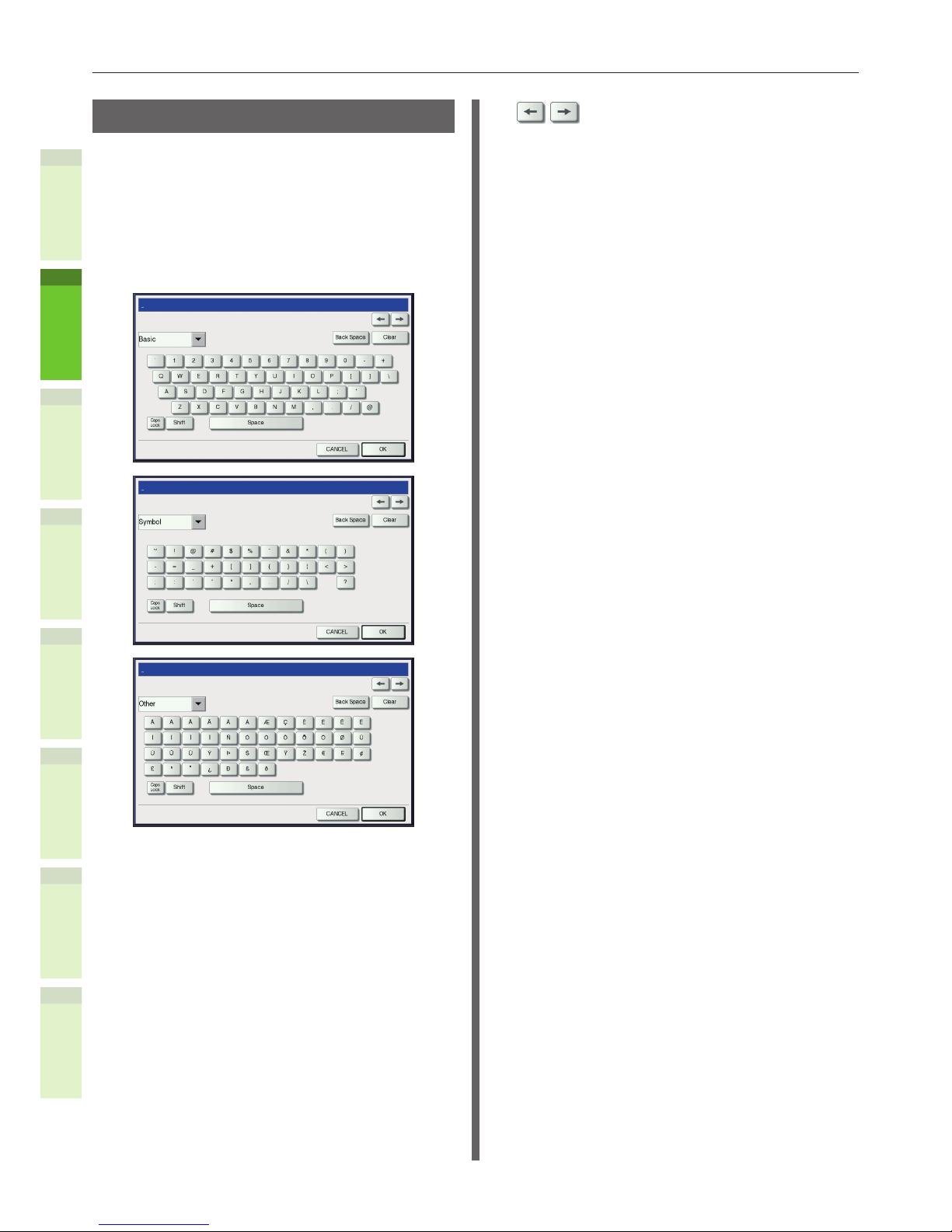
Setting letters
The following menu is displayed when the entry
of any letter is required for scanning or e-Filing,
etc.
Use the buttons on the touch panel for letter
entry.
After entering the letters, press [OK]. The menu
will be changed.
The following buttons are used for letter entry.
[Basic]: Press this to access the basic
keys.
[Symbol]: Press this to access the symbol
keys.
[Other]: Press this to access the special
keys.
[Caps Lock]: Press this to switch capital
letters and small letters.
[Shift]: Press this to enter capital
letters.
[Space]: Press this to enter a space.
: Press these to move the
cursor.
[Back Space]: Press this to delete the letter
before the cursor.
[Clear]: Press this to delete all letters
entered.
[CANCEL]: Press this to cancel the entry
of letters.
[OK]: Press this to x all entered
letters.

- 23 -
Checking the Product
1
2
4
5
6
3
•
Checking the Product
Check that you have everything shown below.
CAUTION
May cause injury!
•
At least three people are needed to safely lift the
machine due to its 60 kg weight (with the Inner
Finisher).
•
Machine
•
Four starter toner cartridges (cyan, magenta,
yellow, and black)
•
Four image drum cartridges (cyan, magenta,
yellow, and black)
Note
•
The image drum cartridges are installed inside the
machine.
•
Client Utilities/User Documentation DVD
•
Power Cord

1
2
4
5
6
3
2
Installing the
Machine
Installation Conditions …………………………… P.25
Unpacking and Installing the Machine
……… P.27
About the o
ption
……………………………………… P.32
Installing Additio
nal Drawer Units …………… P.33
Connecting the Cables
……………………………… P.44
Checking the Copy Operation
…………………… P.48

- 25 -
Installation Conditions
1
2
4
5
6
3
•
Installation Conditions
Q Operating Environment
Your machine must be placed in the following
environment:
Temperature: 10 - 32 °C
Humidity:
20% - 80% RH
(relative humidity)
Maximum wet bulb
temperature
25 °C
Note
•
Avoid condensation. It may cause a malfunction.
•
If your machine is in a location where the humidity is 30%
RH or less, use a humidier or antistatic mat.
Q Installation Precautions
WARNING
•
Do not install the machine near high temperatures
or re.
•
Do not install the machine in places where
chemical reactions are performed, such as a
laboratory.
•
Do not install the machine near ammable liquids,
such as alcohol and paint thinner.
•
Do not install the machine where young children
might get hands or ngers caught in the
machine’s parts.
•
Do not install the machine in an unstable place,
such as a shaky stand or uneven surfaces.
•
Do not install the machine in places with high
humidity, dust, or direct sunlight.
•
Do not install the machine in places with briny air
or corrosive gas.
•
Do not install the machine in places which
experience a lot of vibration.
•
Do not install in places where the ventilation holes
of the machine will be blocked.
CAUTION
•
Do not place the machine directly on high pile
rugs or carpets.
•
Do not install the machine in a closed room with
poor ventilation.
•
If using the machine in a small room for extended
periods, make sure that the room is well
ventilated.
•
Install the machine away from strong magnetic
elds and sources of noise.
•
Install the machine away from monitors or TVs.
•
When moving the machine, make sure that you
support it from both sides.
•
At least three people are needed to safely lift the
machine, due to its weight.
•
If you intend to perform a large print job or use
the machine continuously for extended periods,
make sure that the room is well ventilated.
- 26 -
Installation Conditions
1
2
4
5
6
3
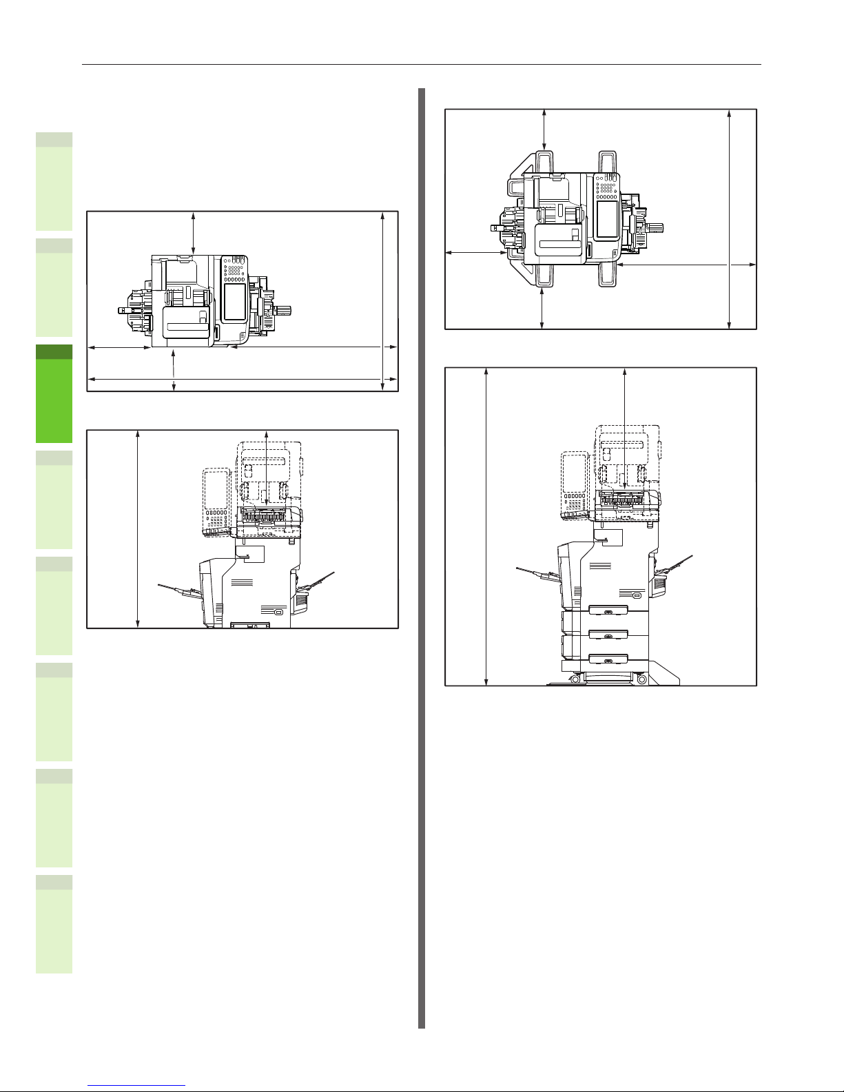
Q Installation Space
Place the machine on a at surface that is wide
enough to accomodate the feet of the machine
securely.
Allow for enough space around the machine.
•
Top View
60cm
20cm
20cm
100cm
(213cm)
(96.5cm)
•
Side View
60cm
(125cm)
•
Top View (when installing the optional tray)
60cm
20cm
20cm
100cm
(124.5cm)
•
Side View (when installing the optional tray)
60cm
(171cm)

- 27 -
Unpacking and Installing the Machine
1
2
4
5
6
3
•
Unpacking and Installing the Machine
1
Remove the protector.
Note
•
The box, packaging, and cushioning material are
needed to transport the machine. Do not dispose of
these items.
(1) Remove the machine from
the box, and then remove the
cushioning.
Note
•
Three people are needed to safely lift this
machine.
Cushioning
Cushioning
(2) Remove the protective tape
from the back and sides of the
machine.
Protective Tape
(3) Pull the document cover open
lever to open the document
cover.
Document Cover
Document Cover Open Lever
(4) Open the inner cover, and
remove the protective sheet and
protectors.
Protective
Sheet
Protector
Inner Cover
(5) Close the document cover.
Document Cover
(6) Open the document holder cover.
Document Holder
Cover
(7) Remove the protective tape.
Protective tape
Protective tape

- 28 -
Unpacking and Installing the Machine
1
2
4
5
6
3
(8) Return the document holder
cover to its original position.
Document
Holder
Cover
(9) Hold the Document holder lever
and lift the Document holder.
Document
Holder
Document
Holder Lock
Lever
(10)
Remove the protective tape.
Protective Tape
(11)
Return the document holder
cover to its original position.
Document
Holder
Cover
(12)
Hold both sides of the bypass
tray and fold it down to open it.
Bypass Tray
(13)
Remove the protective sheet.
Protective Sheet
(14)
Close the bypass tray.
Bypass Tray
- 29 -
Unpacking and Installing the Machine
1
2
4
5
6
3
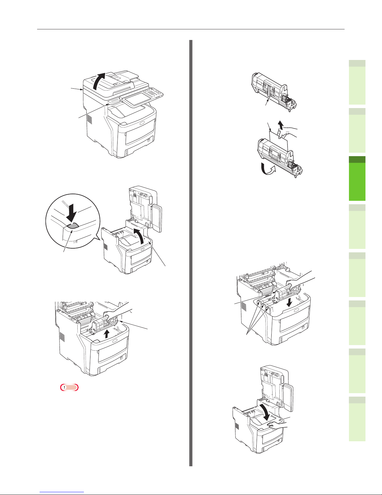
2
Remove the image drum cartridges.
(1) Hold the Document holder lever
and lift the Document holder.
Document
Holder
Document
Holder Lock
Lever
(2) Press the top cover open button
to open the top cover.
Top Cover Open Button
Top Cover
(3) Remove the four image drum
cartridges.
Image Drum
Cartridge
Note
•
The image drum (the green tube) is fragile;
handle it carefully.
•
Do not expose the image drum cartridges to
direct sunlight or strong light (more than about
1,500 lux). Do not expose them to room lighting
for more than ve minutes.
(4) Place the image drum cartridges
on a newspaper.
(5) Peel off the tape that secures the
protective sheet, and carefully
remove it in the direction of the
arrow.
Protective Sheet
Protective Sheet
3
Place the image drum cartridges in
the machine.
(1) Match the label color of each
image drum cartridge with the
label color inside the machine.
(2) Carefully place each of the four
image drum cartridges in the
machine.
Label
Label
(3) Close the top cover.
Top Cover
- 30 -
Unpacking and Installing the Machine
1
2
4
5
6
3
(4) Return the document holder to
its original position.
Note
•
If the operator panel display continues to show
that the toner needs replacing, check that the
lever of each toner cartridge has been fully
turned in the direction of the arrow.
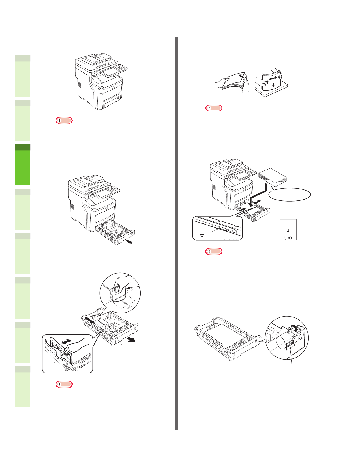
4
Load paper in the drawer cassette.
(1) Open the drawer cassette.
(2) Adjust the paper stop and paper
guide to match the paper size.
Paper Guide
Plate
Paper Stop
Paper
Guide
Note
•
Squeeze the paper stop to adjust its position.
•
Do not remove the cork that is attached to the
plate.
(3) Flex the stack of paper back and
forth a few times. Then, make a
neat stack by straightening its
edges against a level surface.
Note
•
Using paper that is not recommended may
cause the machine to malfunction.
& For details about paper, see "Supported Paper"
(P.56).
(4) Load the paper with the side to
be printed on face down.
Set the direction
of the paper.
The side to be printed
on should be face down.
Mark
Note
•
Load the paper, making sure that it does not
exceed the mark on the paper guide. (300
pieces at 82g/m2 (ream weight 70 kg))
(5) Set the paper size dial to match
the size of the paper.
Rotate the paper size dial until
it shows the size of paper
contained in the cassette.
Paper Size Dial
- 31 -
Unpacking and Installing the Machine
1
2
4
5
6
3
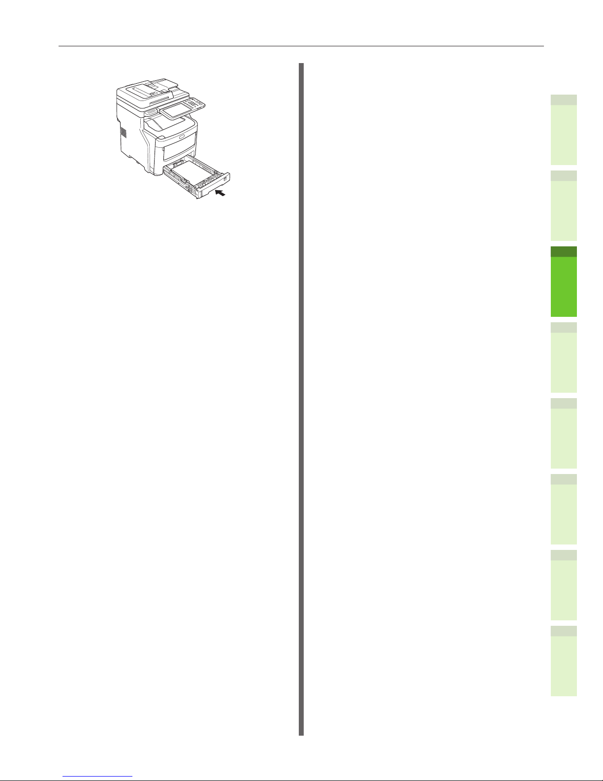
(6) Close the drawer cassette.

- 32 -
About the option
1
2
4
5
6
3
•
About the option
The following options are sold separately, and upgrade the performance of the equipment if installed.
For details, contact your dealer.
Option name Model name Description
1 Large Capacity Feeder KD-1040 This feeder enables you to feed up to 2000
sheets (80 g/m2 or 20 lb. Bond) of A4 or LT
paper.
2 Paper Feed Unit MY-1045 Up to three drawer units can be added to the
machine.
3 Caster GR-1170 The caster unit to set the machine on it. The
anti-tip feet are attached to it.
4 Spacer GR-1160 The spacer adjusts the height of the
machine.
5 Inner Finisher MJ-1038 This nisher enables sort/group nishing and
stapling.
6 Ofine Stapler MJ-1039 This stapler is optional.
7 FAX Unit GD-1340 This is a unit for using the machine as a Fax
machine.
8 Wireless LAN Module GN-1060 This module enables the machine to be used
in a wireless LAN environment.
9 Antenna GN-3020 This is used when the Wireless LAN Module is
installed.
10 e-BRIDGE ID Gate KP-2004, KP-2005 You can log in and use the equipment simply
by holding the IC card over the e-BRIDGE ID
Gate.
11 Data Overwrite Enabler GP-1070 This is an enabler to erase the data stored
temporarily when copying, printing,
scanning, faxing, Internet Fax or network
Fax is performed. It overwrites temporarily
stored data with random data.
12 IPsec Enabler GP-1080 This enables the IPsec function in this
machine.
13 Meta Scan Enabler GS-1010 This enables the Meta Scan function in this
machine.
14 External Interface
Enabler
GS-1020 This enables the EWB function in this
machine.

- 33 -
Installing Additional Drawer Units
1
2
4
5
6
3
•
Installing Additional Drawer Units
Installing additional drawer units will increase the amount of paper you can load. You can install a
maximum of three additional drawers. One drawer can hold 550 sheets of paper (ream weight 55 kg)
at 64 g/m2. By adding an extra tray to the standard drawer and the bypass tray, you can print up to
1530 pages continuously.
Memo
•
The additional trays are called “Drawer 2”, “Drawer 3” and “Drawer 4”.
Additional Drawer Unit Spacer Caster unit
Model Name:N31440A
Caster unit
Screws (22)Anti-tip Foot
Cover (2)
Anti-tip Foot
Rear (2)
Anti-tip Foot
Cover (2)
Anti-tip Foot
(2)
Anti-tip Foot
Side (2)
Note
•
Up to three drawer units can be added to the equipment
without the Inner Finisher. For the equipment with the
Inner Finisher, up to two drawer units including the spacer
can be added.
•
Place the spacer under the additional drawer unit.
1
Open the box and remove the
additional drawer. Remove the
cushioning and protective materials.
2
Turn OFF the power to the machine,
and remove the power cord and
cables.
Note
•
If you leave the power ON, you may damage the
machine.
& For details about how to turn OFF the machine, see
“Turning Power OFF” (P.52).

- 34 -
Installing Additional Drawer Units
1
2
4
5
6
3
3
Attach the caster unit.
Note
•
When the casters are not used, this step is not
necessary.
(1) Attach the anti-tip feet (both
sides and front) with four
screws.
Note
•
Attachment directions are different for the left side
and the right side.
(2) Put the bottoms of the anti-tip
feet (both sides) on the oor,
align the sides to the cabinet
and tighten them with the two
screws each.
Screw Hole
Note
•
Do not tighten the upper screws.
Screw Hole
(3) Tighten the anti-tip foot covers
(both sides) and anti-tip feet
with two screws each.
(4) Align the anti-tip foot cover
(rear) to the rear side of the
anti-tip foot.
(5) Put the bottoms of the anti-tip
feet on the oor and tighten
them with three screws.
Attach the screw in the middle of the
oval cutout and tighten the screw.
- 35 -
Installing Additional Drawer Units
1
2
4
5
6
3
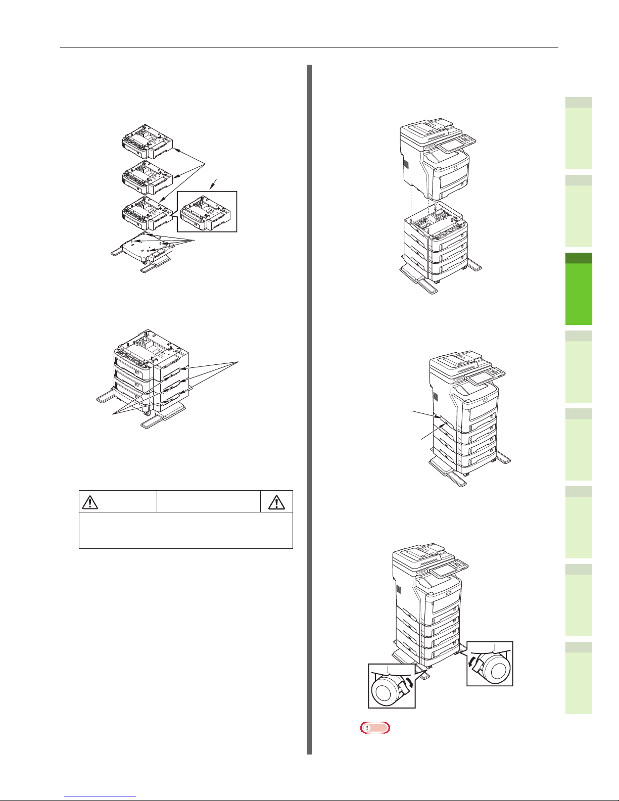
4
Attach the additional drawer and
spacer to the caster unit.
(1) Insert the posts of the cabinet to the
bottom holes of the drawer.
Drawers
Spacer
Post
(2) Fix the drawer with the joint-
option and tighten the screws
with the screw-knob.
JointOption
Screw-Knob
Tighten them on the both sides.
5
Put the machine on the additional
drawer unit.
CAUTION
May cause injury!
•
At least three people are needed to
safely lift the machine due to its 50 kg
weight.
(1) Align the rear sides of the
machine and the additional
drawer unit and place the
machine quietly.
(2) Fix the additional drawer unit
with the joint-option, and tighten
the screw with the screw-knob.
Screw Knob
Joint Option
(3) Press down the lock levers of the
additional drawer unit’s front
casters and lock the casters.
Note
•
For prevention of fall, note the following points in
transporting the equipment and printing.

- 36 -
Installing Additional Drawer Units
1
2
4
5
6
3
-
Do not push the machine when the document
holder is opened.
-
Do not press the drawer cassette when it is
pulled out.
-
Do not push the machine’s rear side when
two or more drawer cassettes are pulled out.
Setting Up the Printer for
Windows
Congure the additional tray by using the printer
driver.
Before printing, you have to congure the
following options:
•
Conguration Settings
To use optional devices such as optional
drawers or the Finisher, you must rst
congure these devices. The features of these
optional devices are not available unless you
inform the system that the optional devices
are installed.
Before printing, you can congure the following
option if necessary:
•
Department Code
You can use department codes to manage
each job. For example, a system administrator
can check how many sheets of copies a certain
department has made. When the Department
code is enabled, you are prompted to enter a
department code before printing. If you enter
the department code in the corresponding
eld in advance, you can print without having
to do this every time. Ask your administrator
about the codes. When SNMP communication
between the equipment and your computer is
enabled, you are also prompted to enter the
code before printing.
Conguring the options
To use this equipment properly, you need to save
the conguration of the options installed on the
[Device Settings] tab menu after you installed
the printer drivers. In the default setting, you
can obtain the conguration data of options
installed automatically by opening the [Device
Settings] tab menu. If SNMP communication
between this equipment and your computer is
not available, or you want to congure options
manually, see the following page:
& P.37 "Conguring options manually"

- 37 -
Installing Additional Drawer Units
1
2
4
5
6
3
Memo
•
When SNMP communication between this equipment and
your computer is enabled, you can retrieve the option
conguration information by clicking [Update Now].
Q Conguring options manually
If SNMP communication between this equipment
and your computer is not available:
Setting the [Device Settings] tab
manually
Note
•
You need to log in to Windows with the “Administrator”
privilege.
1
Click [Start] menu and select
[Devices and Printers].
The Printers folder appears.
2
Select the printer driver for this
equipment, and then click [Printer
properties] in the [File] menu.
The printer driver properties dialog box appears.
•
If the [File] menu is not displayed, press
[Alt].
•
If the dialog box displayed does not
allow the printer driver properties to be
changed, follow the procedure below.
-
For Windows 7, some tab menus
have a button in the printer driver
properties. To change the properties,
click on it. If the properties cannot
be changed, ask your network
administrator.
•
To change a network-installed printer
driver, the administrator privilege is
necessary. Ask your network administrator
for details.
3
Display the [Device Settings] tab
menu, and set the following options.
Model Selection — This sets the model type.
The setup items of the printer driver are changed
according to the model selected.
Note
•
If you select [Universal], you can narrow down
the setup items of the printer driver to those used
commonly in all of the e-STUDIO Series. It is
convenient in such cases as when you are using a
printer driver already installed to other e-STUDIO
Series models.
Option — This option sets whether the following
optional devices are installed.
•
Drawers — This sets whether or not the Paper
Feed Unit or Large Capacity Feeder is installed.
•
Finisher — This sets whether or not the Inner
Finisher is installed.
- 38 -
Installing Additional Drawer Units
1
2
4
5
6
3
Note
•
The Large Capacity Feeder is not available for some
countries or regions.
Memo
•
Setup items differ depending on the model and the
option conguration.
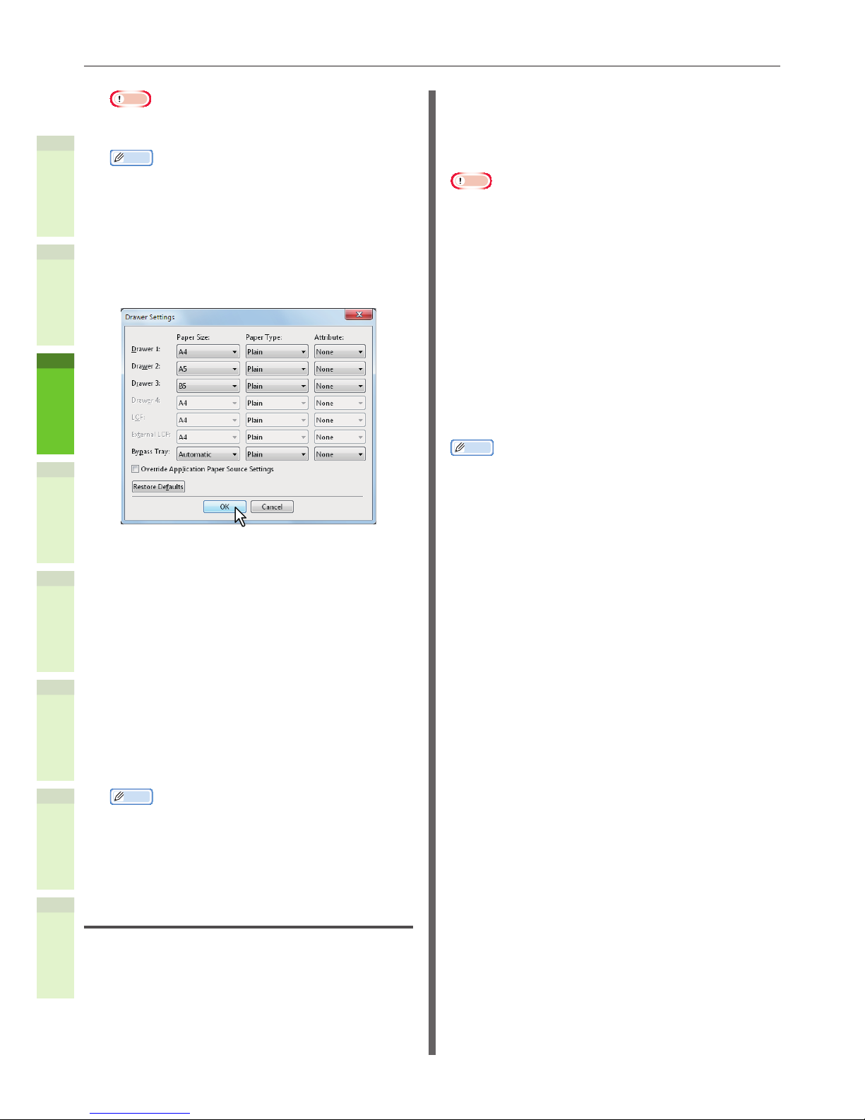
4
Click [Drawer Settings].
The [Drawer Settings] dialog box appears.
5
Set the following options and click
[OK].
Drawer 1 — Select the size and type of paper
that is loaded in the 1st Drawer.
Drawer 2 — Select the size and type of paper
that is loaded in the 2nd Drawer.
Drawer 3 — Select the size and type of paper
that is loaded in the 3rd Drawer.
Drawer 4 — Select the size and type of paper
that is loaded in the 4th Drawer.
Bypass Tray — Select the type of paper that is
loaded in the Bypass Tray.
Override Application Paper Source Settings
— Select this check box to use the paper source
setting in the printer driver rather than the
application setting.
Memo
•
Setup items differ depending on the model and the
option conguration.
6
Click [Apply] or [OK] to save
settings.
Setting the department code
When this equipment is managed by department
codes, you have to enter yours on the printer
driver.
This allows a network administrator to check the
number of copies printed by specic department
members. Also users can check who submitted
the print jobs, by touch panel display and
monitoring tools.
Please ask your administrator whether you
should enter the Department Code.
Note
•
When the User Management setting is enabled, it is
used to manage a print job instead of the Department
Code Management setting. In this case, a user name
that has been entered to log in to your computer is
used for the authentication of the print job. Therefore,
you do not need to set your department code to the
printer driver but you must register your user name in
advance. If your user name is not registered, the print
job is processed as an invalid one according to the User
Authentication Enforcement setting. Also if a print job is
sent in RAW format, it is processed according to the RAW
Print Job setting. For more information about the User
Authentication Enforcement setting or the RAW Print Job
setting, refer to the TopAccess Guide.
•
If the No Limit Black function is enabled, you do not
have to specify the department code when you print a
document with [Black and White] selected for the [Color]
option in the [Basic] tab of printer driver.
Memo
•
How the equipment performs printing for an invalid
department code print job, for which an invalid
department code is specied, varies depending on the
Invalid Department Code Print Job setting that can be set
in the TopAccess Administrator mode and whether SNMP
communication is enabled or not.
-
When SNMP communication is enabled and Invalid
Department Code Print Job is set to [Store to invalid
job list], an error message will be displayed when an
invalid department code is entered.
-
When SNMP communication is disabled and Invalid
Department Code Print Job is set to [Store to invalid
job list], the invalid department code print job will be
stored in the invalid department code print job list
without printing.
-
When the Invalid Department Code Print Job is set to
[Print], the invalid department code print job will be
printed.
-
When the Invalid Department Code Print Job is set to
[Delete], the invalid department code print job will be
deleted.
•
A department code needs to be entered every time you
begin printing. If you have to use a different department
code for each print job, enter it when you begin printing.

- 39 -
Installing Additional Drawer Units
1
2
4
5
6
3
Entering department code
1
Click [Start] menu and select
[Devices and Printers].
The Printers folder appears.
2
Select the printer driver of
this equipment, and then click
[File] menu and select [Printing
Preferences].
•
If the [File] menu is not displayed, press
[Alt].
•
The printing preferences dialog box
appears.
3
Display the [Others] tab menu and
enter your department code in the
[Department Code] box.
In the [Department Code] box, you can enter a
department code within 63 characters.
Memo
•
A department code must consist of one-byte characters
such as numbers from 0 to 9, letters of the alphabet
from A to Z (both capital and small ones), a hyphen
(-), an underscore (_), and a period (.).
4
Click [Apply] or [OK] to save the
settings.
Copying the PPD le for Windows
The Client Utilities/User Documentation DVD
contains a machine description le for popular
Windows applications. For applications not
allowing the automatic installation of PPD les,
copy the PPD le to a proper directory in order
to enable printer-specic settings in the [Print]
dialog box or the [Page] Setup dialog box.
Setting Up the Printer for Mac
OS X
Conguring the printer on Mac OS X
After you copy the PPD le to the library folder
in the System Folder, you can congure the
machine.
The equipment supports the following Macintosh
Printing Services:
•
LPR printing
& P.40 “Conguring LPR printing”
•
IPP printing
& P.41 “Conguring IPP printing”
•
Bonjour printing
& P.42 “Conguring Bonjour printing”
Memo
•
These Macintosh Printing Services are available when the
equipment and your computer are connected over TCP/IP
network.

- 40 -
Installing Additional Drawer Units
1
2
4
5
6
3
Q Conguring LPR printing
1
Open System Preferences and click
[Print & Scan].
2
Click [+].
3
Click [IP] and specify the items as
described below.
Protocol: Line Printer Daemon - LPD
Address: <IP address or DNS name of this
equipment>
Queue: print
Name: <Any Name>
Location: <Any Name>
Print Using: TOSHIBA ColorMFP-X7
Memo
•
For MAC OS X 10.4.x to 10.6x, select TOSHIBA
ColorMFP-X4.
•
In the [Name] box, the name that is entered in the
[Address] box is automatically displayed.
•
The way to select the PPD le differs depending on
countries or regions as follows:
-
For North America
Even when you enter the IP address or DNS name
of this equipment in the [Address] box, the correct
PPD le is not selected in the [Print Using] box.
Therefore, select [Other] in the [Print Using] box,
and select the PPD le TOSHIBA ColorMFP-X7 from
the [/Library/Printers/PPDs/Contents/Resources/
en.lproj] folder.
-
For the UK
When you enter the IP address or DNS name of
this equipment in the [Address] box, the correct
PPD le is automatically selected in the [Print
Using] box. If the correct PPD is not automatically
selected, select [Select a driver to use] and
choose the PPD le displayed in the list.
4
Click [Add].
The [Installable Options] window appears.
5
Set the following options.
•
Model Selection
TOSHIBA e-STUDIO407CSSeries
— Choose this for using
e-STUIDO287CS/407CS/347CS.
•
Finisher
Not Installed — Select this if a nisher is
not installed.
Inner Finisher (1 Tray) — Select this
when the Inner Finisher is installed.
Note
•
Even if you choose [Not Installed] for the Finisher
option during print settings, the nisher options such
as stapling can be selected. If you select the nisher
options for printing but the nisher is not installed,
nisher settings will be ignored and printing will be
performed correctly.

- 41 -
Installing Additional Drawer Units
1
2
4
5
6
3
•
Drawers
Drawer 1
Select this when the drawer 1 is installed.
Drawer 1 and 2
Select this when the drawer 1 and 2 are
installed.
Drawer 1, 2 and 3
Select this when the drawer 1, 2 and 3 are
installed.
Drawer 1, 2, 3 and 4
Select this when the drawer 1, 2, 3 and 4
are installed.
6
Click [OK].
The printer is added to the Printer List.
Q Conguring IPP printing
When you want to setup IPP print queue in the
Mac OS X, follow the procedures below.
1
Open System Preferences and click
[Print & Scan].
2
Click [+].
3
Click [IP] and specify the items as
described below.
Protocol: Line Printer Daemon - LPD
Address: <IP address or DNS name of this
equipment>
Queue: print
Name: <Any Name>
Location: <Any Name>
Print Using: TOSHIBA ColorMFP-X7
Memo
•
For MAC OS X 10.4.x to 10.6x, select TOSHIBA
ColorMFP-X4.
•
In the [Name] box, the name that is entered in the
[Address] box is automatically displayed.
•
The way to select the PPD le differs depending on
countries or regions as follows:
-
For North America
Even when you enter the IP address or DNS name
of this equipment in the [Address] box, the correct
PPD le is not selected in the [Print Using] box.
Therefore, select [Other] in the [Print Using] box,
and select the PPD le TOSHIBA ColorMFP-X7 from
the [/Library/Printers/PPDs/Contents/Resources/
en.lproj] folder.
-
For the UK
When you enter the IP address or DNS name of
this equipment in the [Address] box, the correct
PPD le is automatically selected in the [Print
Using] box. If the correct PPD is not automatically
selected, select [Select a driver to use] and
choose the PPD le displayed in the list
4
Click [Add].
The Installable Options window appears.

- 42 -
Installing Additional Drawer Units
1
2
4
5
6
3
5
Set the following options.
•
Model Selection
TOSHIBA e-STUDIO407CSSeries
— Choose this for using
e-STUIDO287CS/407CS/347CS.
•
Finisher
Not Installed — Select this if a nisher is
not installed.
Inner Finisher (1 Tray) — Select this
when the Inner Finisher is installed.
Note
•
Even if you choose [Not Installed] for the Finisher
option during print settings, the nisher options such
as stapling can be selected. If you select the nisher
options for printing but the nisher is not installed,
nisher settings will be ignored and printing will be
performed correctly.
•
Drawers
Drawer 1
Select this when the drawer 1 is installed.
Drawer 1 and 2
Select this when the drawer 1 and 2 are
installed.
Drawer 1, 2 and 3
Select this when the drawer 1, 2 and 3 are
installed.
Drawer 1, 2, 3 and 4
Select this when the drawer 1, 2, 3 and 4
are installed.
6
Click [OK].
The printer is added to the Printer List.
Q Conguring Bonjour printing
1
Open System Preferences and click
[Print & Scan].
2
Click [+].
3
Click [Default] and select the MFP of
the Bonjour connection displayed in
the list.

- 43 -
Installing Additional Drawer Units
1
2
4
5
6
3
Memo
•
In the [Name] box, the device name that you
selected in the list is automatically displayed.
•
The way to select the PPD le differs depending on
countries or regions as follows:
-
For North America
Even when you select the equipment from the
list, the correct PPD le is not selected in the
[Print Using] box. Therefore, select [Other] in the
[Print Using] box, and select the PPD le TOSHIBA
ColorMFP-X7 from the [/Library/Printers/PPDs/
Contents/Resources/en.lproj] folder.
-
For the UK
When you select the equipment from the list,
the correct PPD le is automatically selected in
the [Print Using] box. If the correct PPD is not
automatically selected, select [Select a driver to
use] and choose the PPD le displayed in the list.
4
Click [Add].
The [Installable Options] window appears.
5
Set the following options.
•
Model Selection
TOSHIBA e-STUDIO407CSSeries
— Choose this for using
e-STUIDO287CS/407CS/347CS.
•
Finisher
Not Installed — Select this if a nisher is
not installed.
Inner Finisher (1 Tray) — Select this
when the Inner Finisher is installed.
Note
•
Even if you choose [Not Installed] for the Finisher
option during print settings, the nisher options such
as stapling can be selected. If you select the nisher
options for printing but the nisher is not installed,
nisher settings will be ignored and printing will be
performed correctly.
•
Drawers
Drawer 1
Select this when the drawer 1 is installed.
Drawer 1 and 2
Select this when the drawer 1 and 2 are
installed.
Drawer 1, 2 and 3
Select this when the drawer 1, 2 and 3 are
installed.
Drawer 1, 2, 3 and 4
Select this when the drawer 1, 2, 3 and 4
are installed.
6
Click [OK].
The printer is added to the Printer List.

- 44 -
Connecting the Cables
1
2
4
5
6
3
•
Connecting the Cables
Connecting the Network
Cables
1
Procure a network cable and a hub.
Note
•
A network cable and hub are not provided with
this product. Procure a network cable (category 5,
twisted pair, straight) and a hub separately.
<Network Cable> <Hub>
2
Connect the machine to the
network.
(1) Insert the network cable into the
network interface connector of
the machine.
(2) Insert the network cable to the
hub.
Network
Interface
Connector
Connecting the USB cable
1
Prepare a USB cable.
Note
•
A USB cable is not provide with this product. Procure
a USB 2.0 cable separately.
•
Use a USB 2.0 Hi-Speed cable for a USB 2.0 HiSpeed connection.
2
Connect the USB cable.
(1) Insert the end of the USB cable
into the USB interface connector
of the machine.
Note
•
Be careful not to insert the USB cable into the
network interface connector. This may cause
damage.
(2) Insert the end of the USB cable
into the USB interface connector
of the computer.
USB Interface
Connector

- 45 -
Connecting the Cables
1
2
4
5
6
3
Connecting to the telephone
line
The telephone line cable connection method
varies depending on the operating environment
you are using. Make the following connection
while taking into consideration your personal
environment.
Note
•
Connection is not possible to an ISDN network. Use a
terminal adaptor (TA) to connect to an ISDN network, and
connect to the LINE connector of the machine.
•
Make sure that you use the telephone cable that is
provided with the product. If you use a different telephone
cable, a malfunction may occur.
1
Make the connection while
taking into consideration your
environment.
•
When connecting to a public network
(When using the network as a dedicated
fax (when the telephone line is not
connected to the machine)).
Insert the telephone line cable into the [LINE
connector] of the machine.
Insert the cover provided with this machine into
the [TEL connector].
LINE Connector
TEL Connector
Public Network
(Analog)
Telephone Line Cable
Note
•
Make sure that you do not mistakenly insert the
cable into the [TEL connector].
•
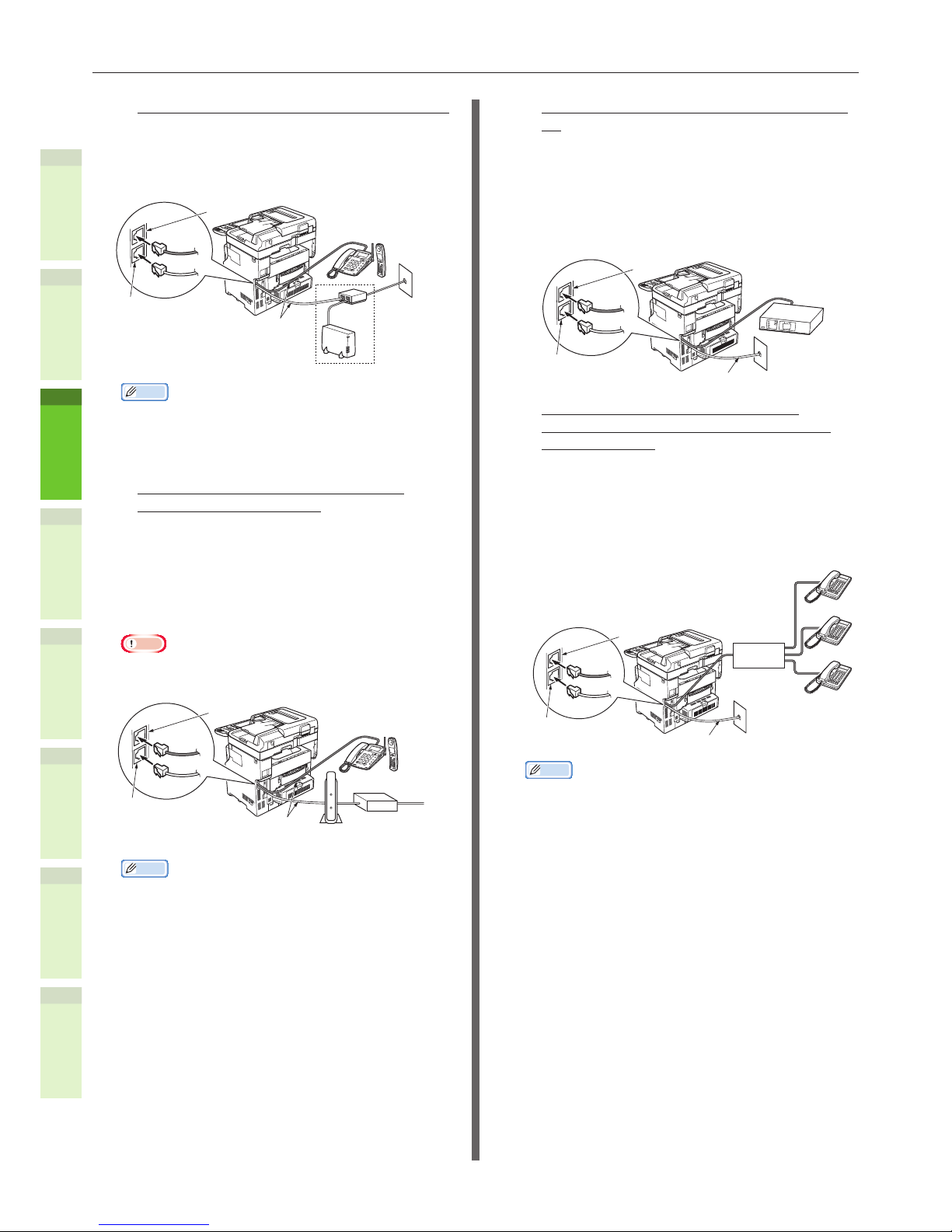
When connecting to a public network
(When connecting the telephone to the
machine)
Insert the telephone line cable (that is connected
to the public network (analog)) into the [LINE
connector].
Insert the telephone line cable from an external
telephone into the [TEL connector].
LINE Connector
TEL Connector
Public Network
(Analog)
External phone
such as a
cordless phone
Telephone Line Cable
Note
•
You can connect only one telephone to the TEL
connector of the machine.
•
Do not make a branch connection (parallel
connection) between the machine and telephone. If
you make a branch connection (parallel connection),
the following problems may occur. The machine may
also start to operate abnormally.
•
When sending or receiving faxes, fax images
may distort and communication errors may
occur when picking up the receiver of the
telephone connected in branch connection
(parallel connection).
•
When the phone rings, the ring may be delayed
or suddenly stop. In addition, you may not be
able to receive a fax that has been sent.
Public Network (Analog) Public Network (Analog)
Memo
•
For direct wiring, separate work is required. Contact
your telephone company for assistance.
- 46 -
Connecting the Cables
1
2
4
5
6
3
•
When connecting to an ADSL environment
Insert the telephone line cable (connected to
the ADSL modem) into the [LINE connector].
Insert the telephone line cable from an external
telephone into the [TEL connector]
LINE Connector
Telephone Line Cable
TEL Connector
Public Network
(Analog)
External phone such
as a cordless phone
ADSL Modem
Splitter
Memo
•
If you do not intend to dial (outgoing call), turn OFF
the [Dial Tone Detection].
•
If you cannot send or receive a FAX, turn OFF the
[Super G3].
•
When connecting to an optical ber
telephone (IP telephone)
Insert the telephone line cable (connected
to a telephone compatible with an optical
ber telephone (IP telephone)) to the [LINE
connector].
Insert the telephone line cable from an external
telephone into the [TEL connector].
Note
•
When communicating with super G3, check that the
quality of the provider communication is guaranteed.
LINE Connector
Optical Fiber Telephone (IP
Telephone) Compatible Telephone
Optical Fiber Cable
TEL Connector
Telephone Line Cable
Optical Network
Unit (ONU)
External phone such
as a cordless phone
LAN
Cable
*Insert the telephone cable into the slot.
Memo
•
If you do not intend to dial (outgoing call), turn OFF
the [Dial Tone Detection].
•
If you cannot send or receive a FAX, turn OFF the
[Super G3].
•
When connecting the CS tuner and digital
TV
Insert the telephone line cable (that is connected
to the public network (analog)) into the [LINE
connector].
Insert the telephone cable (that is connected
to the CS tuner or digital TV) into the [TEL
connector].
LINE Connector
Public Network
(Analog)
TEL Connector
Telephone Cable
CS Tuner or
Digital TV
•
When connecting a private branch
exchange (PBX), home telephone, and
business phone
Insert the telephone line cable (that is connected
to the public network (analog)) into the [LINE
connector].
Insert the telephone line cable (that is connected
to a controller such as the PBX) into the [TEL
connector].
LINE Connector
Telephone Cable
TEL Connector
Public Network
(Analog)
Controller
such as PBX
Memo
•
For home phones, connect multiple telephones to
telephone lines 1 and 2. This is a simple switch
device for household use that can use extension
telephones and door telephones.
•
For business phones, the lines are shared using
multiple telephones with a capacity of three
telephone lines or more. This is a simple switch
device that can use telephones such as extension
telephones.
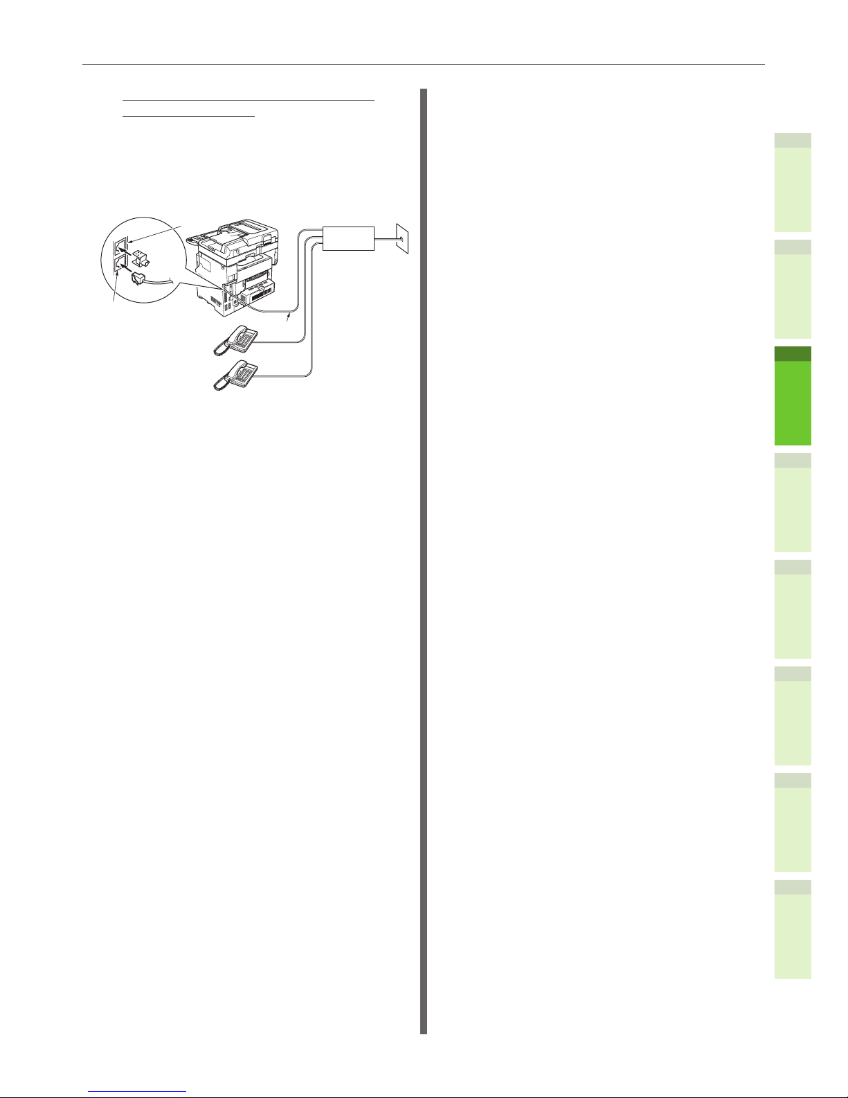
- 47 -
Connecting the Cables
1
2
4
5
6
3
•
When connecting the telephone as an
extension telephone
Insert the telephone line cable (that is connected
to a controller such as the PBX) into the [LINE
connector].
Insert the cover provided with this machine into
the [TEL connector].
LINE Connector
Telephone
Cable
TEL Connector
Public Network
(Analog)
Controller
such as PBX

- 48 -
Checking the Copy Operation
1
2
4
5
6
3
•
Checking the Copy Operation
&
For details about how to turn ON the machine, see “Turning Power ON” (P.51).
Checking the copy operation
Check the copy operation of the machine.
Memo
•
The following procedure uses the factory settings.
•
Press the [COPY] button to switch to the copy screen.
1
Place the document.
•
When using the automatic document feed
(ADF).
Place the documents face up, and load the
documents so that the rst page is on top.
•
When using the platen (glass surface).
Place the documents face down, and
place the corner of the document so that
it aligns with the setting reference at the
back and to the left side.
& See “About Document Copies” (P.72)
2
Press the [START] button.
The copy starts.

1
2
4
5
6
3
3
Turning
Power ON/OFF
Precautions about the Power Supply ………… P.50
Turning Power ON
…………………………………… P.51
Turning Power OFF
………………………………… P.52
Reducing Power Co
nsumption When the Machine
is not in Use (Power Save Mode)
……………… P.53

- 50 -
Precautions about the Power Supply
1
2
4
5
6
3
•
Precautions about the Power Supply
WARNING
There is a risk of electric shock and/or re.
•
Be sure to turn off the power when attaching or removing the AC cable and ground wire.
•
Be sure to connect the ground wire to a dedicated grounding terminal. Please consult with the retail store
where you purchased this product if the power supply cannot be grounded.
•
Do not connect the ground wire to an object such as a water pipe, a gas pipe, a telephone wire, or a lightning
rod under any circumstances.
•
Be sure to connect to the ground terminal before connecting the power cord to the power supply plug. Also,
keep the power supply plug away from the power supply.
•
Always grip the cord by its plug when removing it from the outlet.
•
Insert the power plug fully into the outlet.
•
Do not touch the power cord or machine if your hands are wet.
•
Place the power cord where it will not be stepped on. Do not place any objects on the power cord.
•
Do not tie or bundle the power cord.
•
Do not use a damaged power cord.
•
Do not use multi-outlet adapters.
•
Do not connect this machine and other electrical products to the same wall outlet. In particular, sharing an
outlet with electrical products such as air conditioners, copiers, or shredders may cause the machine to operate
incorrectly because of electric noise. If this is unavoidable, use a commercial noise lter or a commercial noise
cut transformer.
•
Use the power cord provided with the product and connect it directly to the ground terminal. Do not use any
other power cord with the machine.
•
Do not use an extension cord. If using an extension cord is unavoidable, make sure that you use a product
rated at 15 A or more.
•
Use of an extension cord may cause the machine to operate incorrectly because of AC voltage drop.
•
Periodically remove the power supply plug from the outlet and clean the base of the prongs and between the
prongs. Dust may adhere to the plug if you leave it in the outlet for extended periods of time. This can cause a
short circuit and lead to a re.
•
During printing, do not shut off the power supply or pull out the power plug.
•
Unplug the power cord if you do not intend to use the machine for an extended period of time, such as a long
vacation.
•
Do not use the power cord provided with this product with other products.
•
The power supply must meet the following conditions:
Current (AC): 110 - 127 VAC (Range 99 - 140 VAC)
220 - 240 VAC (Range 198 - 264 VAC)
Frequency: 50Hz or 60Hz ± 2%
•
If the power supply is unstable, use a voltage regulator.
•
The maximum power consumption of this machine is 1300 W. Ensure that the power supply is
sufcient to operate this machine.
•
We do not guarantee operations when an uninterruptible power system (UPS) or inverter is used. Do
not use an uninterruptible power system (UPS) or inverter.

- 51 -
Turning Power ON
1
2
4
5
6
3
•
Turning Power ON
1
Connect the power supply cord.
(1) Check that the power switch has
been turned OFF (O).
(2) Connect the power supply cord to
the machine.
(3) Insert the power supply plug into
the outlet.
2
Turn ON the power switch.
(1) Check that there are no
documents in the document
holder.
(2) Check that there are no
documents in the document tray
of the automatic document feed.
(3) Turn ON the power switch (I).

- 52 -
Turning Power OFF
1
2
4
5
6
3
•
Turning Power OFF
Make sure you follow this procedure when
turning OFF the power.
Note
•
Do not abruptly turn OFF the power supply. This may
damage the machine.
1
Press the [ON/OFF] button until a
“pip” sound is heard.
2
The following screen appears for a
while.
Memo
•
When the screen above disappears, turn OFF the power
switch.
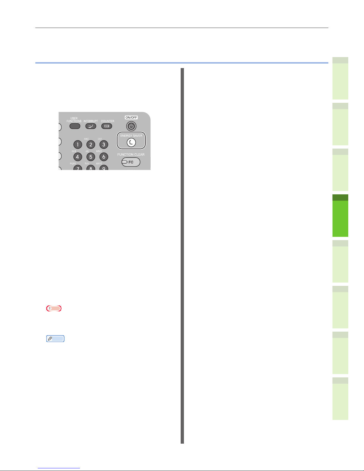
- 53 -
Reducing Power Consumption When the Machine is not in Use (Power Save Mode)
1
2
4
5
6
3
•
Reducing Power Consumption When the Machine
is not in Use (Power Save Mode)
When the machine has been idle for a certain
period of time, it automatically enters power
save mode to reduce power consumption. You
can enter the power save mode manually by
pressing the [ENERGY SAVER] button on the
operator panel.
Q Power Save Mode
•
Press the [ENERGY SAVER] button to enter power
save mode.
•
When the machine is idle for 5 minutes, it
automatically enters the power save mode.
& If you want to change the amount of time that
elapses before entering the power save mode,
press the [USER FUNCTION] button, and then
congure in [ADMIN] - [GENERAL] - [ENERGY
SAVER] - [AUTO POWER SAVE].
•
You can send loaded documents to memory or print
received documents even in power save mode.
•
When in power save mode, the number of times an
incoming call will ring will be longer than the set
value.
•
When in power save mode, the [ENERGY SAVER]
button glows green.
•
When you press the [ENERGY SAVER] button in
power save mode, the machine returns to normal
standby mode.
Note
•
If an error occurs and a message appears, as when
the toner is empty, the [ENERGY SAVER] button can
not be used.
Memo
•
When restoring the machine from power save mode,
open and close the document holder cover, otherwise
the document size will not correctly be recognized
if you have placed a document on the platen (glass
surface).

1
2
4
5
6
3
4
About Paper
About Paper …………………………………………… P.55
How to Load the Paper
…………………………… P.62
Paper Output
………………………………………… P.70

- 55 -
About Paper
1
2
4
5
6
3
•
About Paper
The Width and Length of the Paper
When expressing the size of paper, X represents the width of the paper and Y represents its length.
•
Drawer Cassette
•
Bypass Tray

- 56 -
About Paper
1
2
4
5
6
3
Supported Paper
For high quality printing, use paper that meets the requirements for quality, thickness, and surface
nish. If not using recommended paper, test the print quality and the movement of the paper
beforehand to avoid problems.
Q About the type, size, and thickness of the paper.
Note
•
There are limitations to the paper source or the output method depending on the type, size, and thickness of the paper.
Paper Type Paper Size mm (inch) Paper Thickness
Plain Paper A4 210×297 64 to 200 g/m
2
For duplex print, 64 to 105 g/m
2
Supported paper sizes are A4, A5, B5,
Letter, Legal (13 inch), Legal (13.5
inch), Legal (14 inch), executive, and
tabloid.
A5 148×210
A6 105×148
B5 182×257
Letter 215.9×279.4 (8.5×11)
Legal (13 inch) 215.9×330.2 (8.5×13)
Legal (13.5 inch) 215.9×342.9 (8.5×13.5)
Legal (14 inch) 215.9×355.6 (8.5×14)
Executive 184.2×266.7 (7.25×10.5)
Custom Width 64 - 216
Length 210 - 356
64 to 200 g/m
2
Envelope Com-10 104.8×241.3 (4.125×9.5) Envelopes should be 24lb paper, with
folded aps.
Label A4 210×297 0.1-0.2mm
Letter 215.9×279.4 (8.5×11)
Partly-Printing
Paper
Complies with the criteria for plain paper. 64-200g/m
2
(ream weight 55-172kg)
Color Paper Complies with the criteria for plain paper. 64-200g/m
2
(ream weight 55-172kg)
Index Card Index Card 76.2×127 (3×5)

- 57 -
About Paper
1
2
4
5
6
3
Q Paper Recommendations
Your machine will handle a variety of print
media, including a range of paper weights and
sizes.
This section provides general advice on choice of
media, and explains how to use each type.
The best performance will be obtained when
using standard 75 - 90 g/m2 paper designed for
use in copiers and laser printers.
Use of heavily embossed or very rough textured
paper is not recommended.
Pre-printed stationery can be used, but the ink
must not offset when exposed to the high fuser
temperatures used in the printing process.
Envelopes should be free from twist, curl or
other deformations. They should also be of the
rectangular ap type, with glue that remains
intact when subjected to hot roll pressure fusing
used in this type of machine. Window envelopes
are not suitable.
Labels should also be of the type recommended
for use in copiers and laser printers, in which the
base carrier page is entirely covered by labels.
Other types of label stock may damage the
machine due to the labels peeling off during the
printing process.
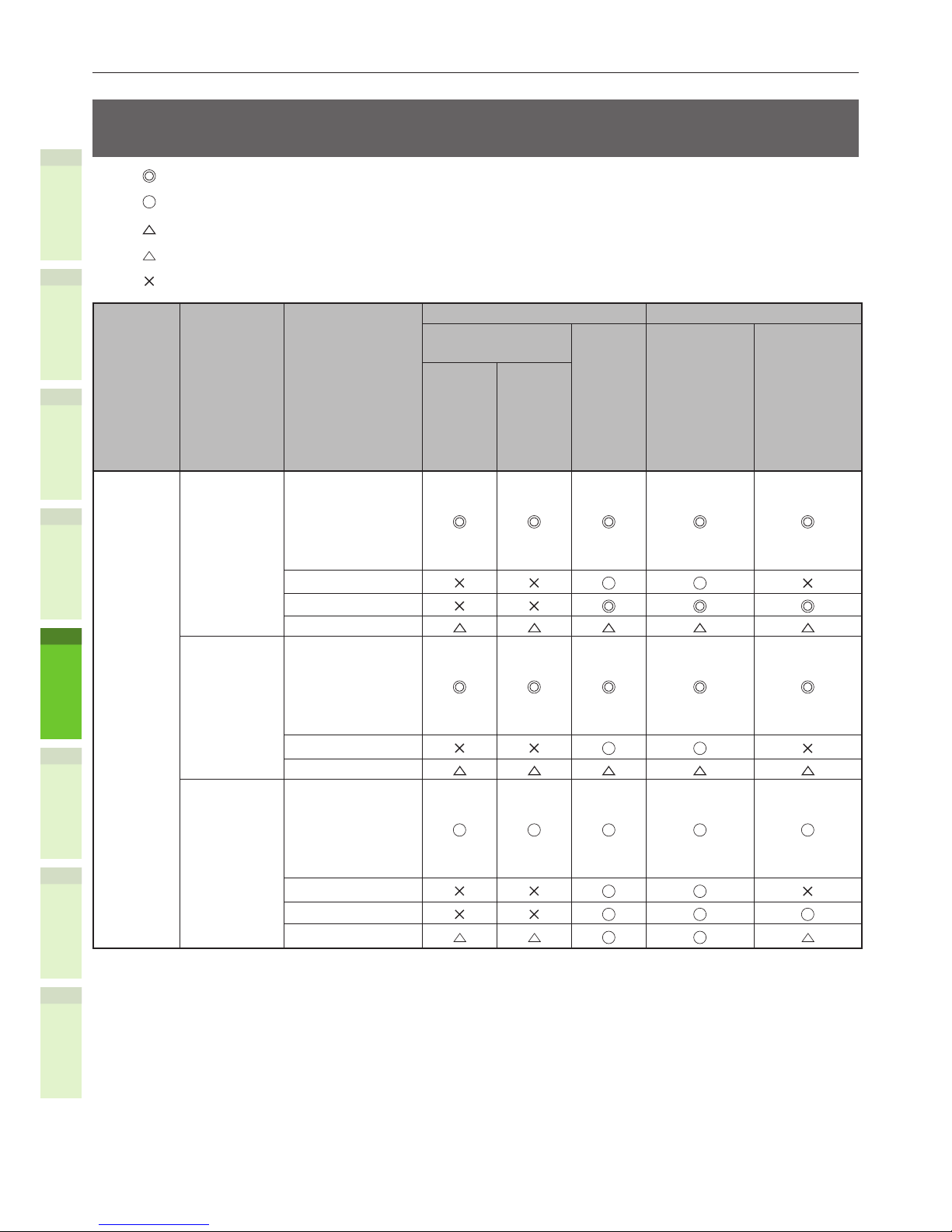
- 58 -
About Paper
1
2
4
5
6
3
Selecting the paper source and output method for each paper
type.
: You can use one-sided or two-sided (duplex) printing.
: You can use one-sided printing only.
:
You can use various sizes of print media (one- or two-sided printing).
:
You can use various sizes of print media (one-sided printing only).
:
Unusable.
Paper
Type
Paper
Thickness
Paper Size
Paper Source Output Method
Drawer
Cassette*
1
Bypass
Tray
Manual
Face Up
(Page
Output from
the front)
Face Down
(Page
Output from
the back)
Drawer
1
Drawer
2
*
2
Drawer
3
Drawer
4
Plain Paper 64-82g/m2 A4, A5
B5, letter
Legal (13 inch)
Legal (13.5 inch)
Legal (14 inch)
Executive
A6
Tabloid
Custom*
3
*
4
*
4
*
4
83-105g/m2 A4, A5
B5, letter
Legal (13 inch)
Legal (13.5 inch)
Legal (14 inch)
Executive
A6
Custom*
3
*
4
*
4
*
4
106-120g/m2 A4, A5
B5, letter
Legal (13 inch)
Legal (13.5 inch)
Legal (14 inch)
Executive
A6
Tabloid
Custom*
3
*
4
*
4
*
4

- 59 -
About Paper
1
2
4
5
6
3
Paper
Type
Paper
Thickness
Paper Size
Paper Source Output Method
Drawer
Cassette*
1
Bypass
Tray
Manual
Face Up
(Page
Output from
the front)
Face Down
(Page
Output from
the back)
Drawer
1
Drawer
2
*
2
Drawer
3
Drawer
4
Plain Paper 121-176g/m2
(ream weight
104-151kg)
A4, A5
B5, letter
Legal (13 inch)
Legal (13.5 inch)
Legal (14 inch)
Executive
A6
Tabloid
Custom*
3
*
4
177-200g/m2
(ream weight
152-172kg)
A4, A5
B5, letter
Legal (13 inch)
Legal (13.5 inch)
Legal (14 inch)
Executive
A6
Custom*
3
Envelope
*
5
- Com-10, DL
C5, C4
Label*
5
- A4
Index Card Index Card
*1
: The order of the drawers from the bottom up is Drawer 1, Drawer 2, Drawer 3, and Drawer 4
*2
: Drawer 2, Drawer 3, and Drawer 4 are optional.
*3
:
Custom: Width of 64 to 216 mm and a height of 127 to 1321 mm. Printable size for duplex printing:
Width of 148 to 216 mm and a height of 210 to 356 mm.
*4
: Width of 148 to 216 mm and a height of 210 to 356 mm.
*5
: When using postcards, envelopes, and labels, the printing speed becomes slower.
Note
•
If you load the paper vertically ( ) in the drawer, but congure the machine to horizontal ( ), this will slow the print
speed.
•
If you load A6 paper, but congure the machine to A5 size and a paper width of 148 mm or less (A5 width), this will slow
the print speed.
•
If you congure the paper size to [Custom] by using the operator panel, the [Paper Size Dial] setting of the drawer
cassette becomes unavailable.

- 60 -
About Paper
1
2
4
5
6
3
Printable Areas of the Paper
The area of the paper that cannot be printed on
is shown below.
Area (A) of 4 mm ± 2 mm from the front end of
the paper.
Area (B) of 4 mm ± 2 mm from the back end of
the paper.
Area (C) of 4 mm ± 2 mm from the end of the
paper.
Output Direction
A, B, C, 4mm ± 2mm
About Symbols
The ( ) symbol indicates vertical placement of
the paper when viewed from the front of the
machine.

- 61 -
About Paper
1
2
4
5
6
3
Storing Paper
Be sure to store paper properly, otherwise it
can absorb moisture, discolor, or curl. If that
happens, it can affect print quality and cause
paper misfeeds. Do not open the packaging until
you intend to use the paper.
Q Store paper under the following
conditions.
•
Inside a cabinet or other dry, dark place.
•
On a at surface.
•
Temperature 20°C and humidity: 50% RH
Q Do not store paper under the
following conditions.
•
Directly on the oor
•
In direct sunlight
•
Near the inside of an exterior wall
•
On an uneven surface
•
Where static electricity may be generated
•
In places that are excessively hot or which
experience rapid temperature changes.
•
Near a copier, air conditioner, heater, or
duct.
Note
•
Storing paper for long periods of time may cause
printing problems.
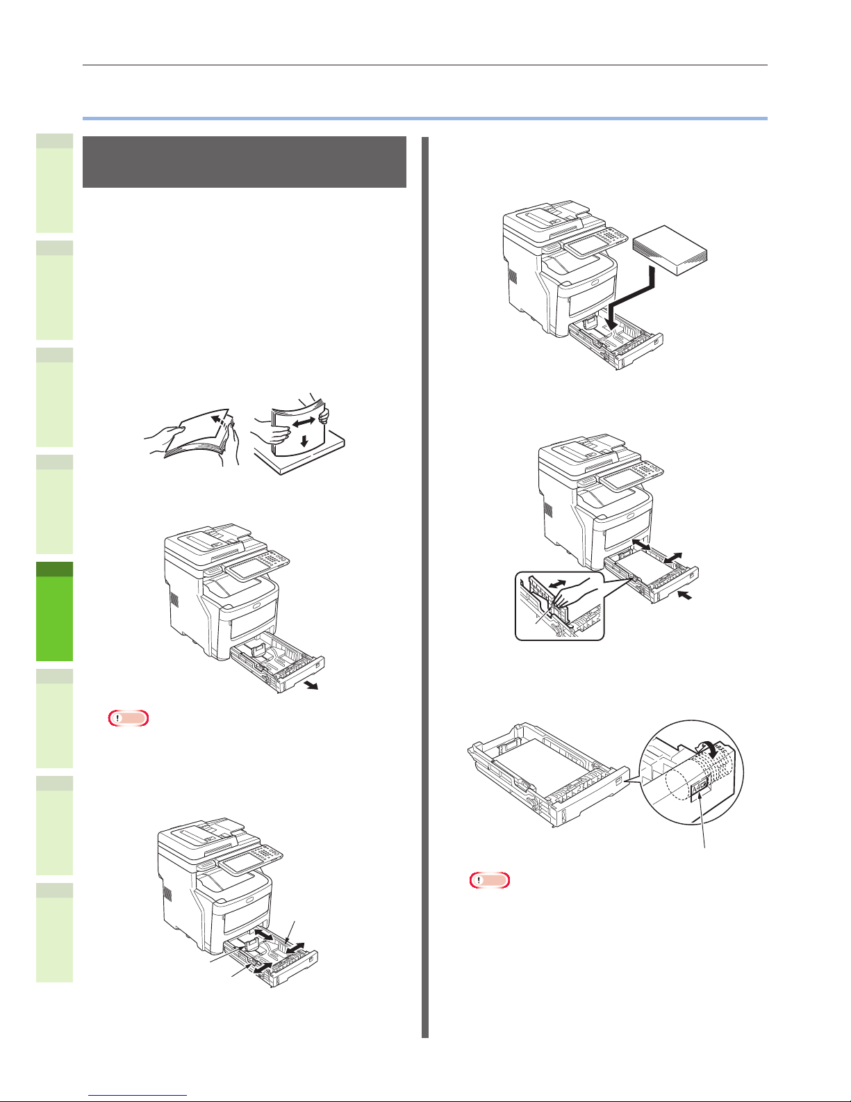
- 62 -
How to Load the Paper
1
2
4
5
6
3
•
How to Load the Paper
Loading the paper in the
drawer cassette
Plain paper is the only type of paper that can be
loaded in the drawer cassette.
Follow this procedure to load the paper in the
drawer cassette. After you have loaded the
paper, congure the paper type and thickness by
using the operator panel.
1
Flex the stack of paper back and
forth a few times. Then, make a neat
stack by straightening its edges
against a level surface.
2
Open the drawer cassette.
Note
•
Do not remove the cork that is attached to the plate.
3
Adjust the paper guide and paper
stop to t the paper size, and make
sure they are secure.
Paper Stop
Paper Guide
Paper Guide
4
The side that you want to print on
should be placed face down when
loading the paper.
5
Check the paper guide, and make
sure that the paper is secure.
Paper
Guide
6
Rotate the paper size dial until it
displays the size of the paper you
have loaded.
Paper Size Dial
Note
•
Match the orientation of the loaded paper.

- 63 -
How to Load the Paper
1
2
4
5
6
3
7
Return the drawer cassette to its
original position.
Setting the paper size dial
After you have loaded paper in drawer 1 or
drawer 2/3/4 (optional), you must set the paper
size dial to match the way the paper was placed
in the drawer cassette.
This symbol indicates vertical placement of
the paper when viewed from the front.
Paper Size Dial
•
When selecting ( ).

- 64 -
How to Load the Paper
1
2
4
5
6
3
Using the Bypass Tray
Use the bypass tray when you want to print on
plain paper, postcards, envelopes, OHP lm,
or labels. The side you want to print on should
be placed face up. After loading the paper,
congure its size, type, and thickness by using
the operator panel.
1
Hold the bypass tray on both sides,
and fold it down.
Bypass Tray
2
Pull the folded paper support
forward between manual guides.
3
Pull the paper support out.
Paper Support
Bypass Tray
4
Adjust the manual guides to t the
paper width.
Bypass Tray
Manual Guide
Manual Guide
5
Press down the back of the bypass
tray.
6
With the side you want to print on
facing up, insert the edge of the
paper into the back of the bypass
tray.
Note
•
Loaded paper should not exceed the [] mark on the
manual guide. You can load up to 100 pages at 82g/
m
2
(ream weight 70 kg)
7
Push the blue set button.
Set Button
(Blue)
Note
•
Do not mix papers of different size, type, or
thickness.
•
When adding paper to the bypass tray, take out any
paper already inserted, then add the extra paper and
realign the paper into a tidy stack.
•
Curled or warped postcards or envelopes may cause
misfeeds. Try to use material that is not curled. Any
curl of 2 mm or more should be corrected.
•
Do not place any material on the bypass tray other
than paper for printing. Do not use excessive force
when raising or pushing the bypass tray.
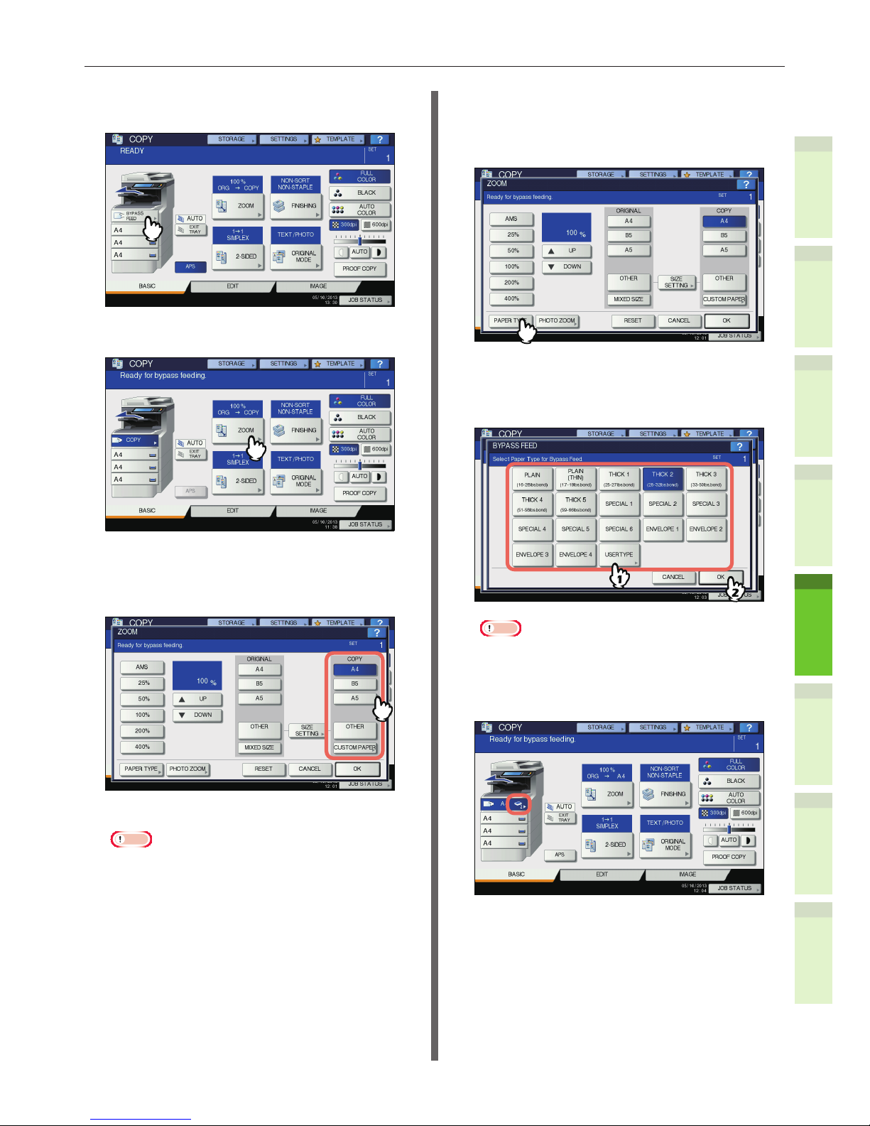
- 65 -
How to Load the Paper
1
2
4
5
6
3
8
Press [BYPASS FEED] on the touch
panel.
9
Press [ZOOM] on the touch panel.
10
Select the same size button under
“COPY” as that of the paper you
placed on the bypass tray.
The paper size is now set.
Note
•
If the paper size is not selected in this step, copying
may be slowed down.
11
Press [PAPER TYPE] on the touch
panel if the paper type of the paper
you placed on the bypass tray is
other than plain paper.
12
Press the button of the same paper
type as the paper you placed on the
bypass tray. Then press [OK].
Note
•
If you select a wrong paper type, this could cause a
paper misfeed or signicant image trouble.
•
When you select a paper type, you can conrm it
with the icons displayed on the equipment status
indication area as shown below.

- 66 -
How to Load the Paper
1
2
4
5
6
3
Paper type Icon
PLAIN −
PLAIN (THIN)
THICK 1
THICK 2
THICK 3
THICK 4
THICK 5
SPECIAL 1
SPECIAL 2
SPECIAL 3
SPECIAL 4
SPECIAL 5
SPECIAL 6
ENVELOPE 1
ENVELOPE 2
ENVELOPE 3
ENVELOPE 4
About “BACK”
When making 2-sided copies manually, select a
paper type for one side and make a copy of it,
and then select “(BACK)” of the same paper type
for the other side.
Example: When making a 2-sided copy on THICK
2 paper
1. Place paper on the bypass tray.
2. Select “THICK 2” for the paper type and
start copying.
3. Place the paper copied in step 2 on the
bypass tray again with its copied side up.
4. Select “THICK 2 (BACK)” and start copying.
Note
•
Automatic 2-sided copying can be applied to plain
paper and THICK 1.
•
For envelopes, only 1-sided copying can be
performed on its front side.
13
After setting the paper size and
type, press [OK].
The menu returns to the BASIC menu.
14
Select other copy modes as
required, and then press the
[START] button on the control
panel.
Note
•
When you copy on sheets of OHP lm, remove the
copied OHP lm one sheet at a time as they exit
onto the receiving tray. If the sheets of OHP lm pile
up, they may get curled and may not be projected
properly.
15
After printing is completed, close
the bypass tray.
(1) Close the paper support.
Bypass Tray
Paper Support
(2) Slide each manual guides back to
its original position.
Bypass Tray
Manual Guide
Manual Guide
(3) Fold up the bypass tray.
Bypass Tray
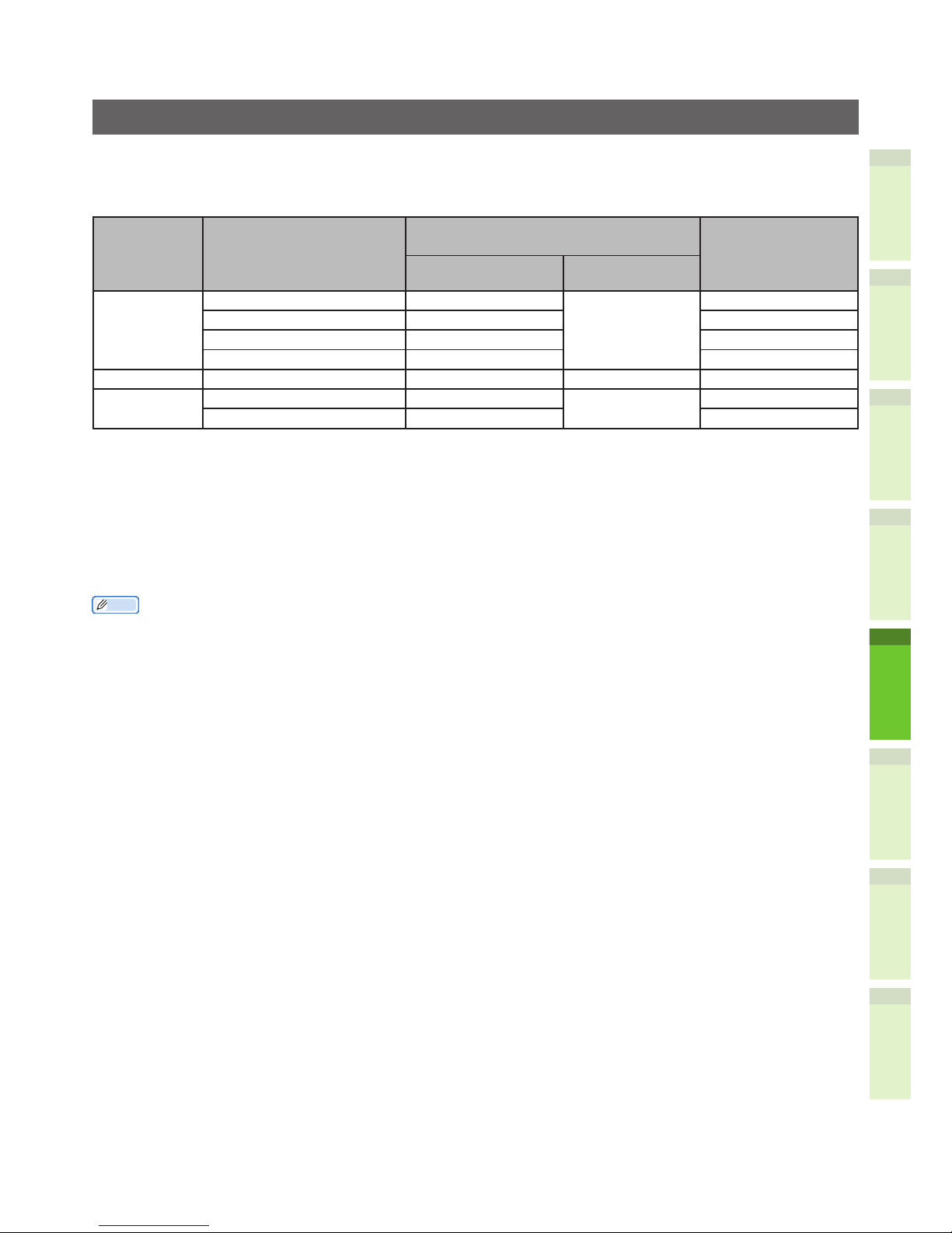
- 67 -
1
2
4
5
6
3
Conguring the drawer cassette
Match the drawer cassette to the loaded paper. Refer to the following table and congure paper type and
thickness by using the operator panel.
Complete the settings by pressing the [USER FUNCTION] button, and then [DRAWER] - [PAPER TYPE].
Paper Type Paper Thickness
Setting value for the operator
panel
Setting of the
[Paper Thickness]
of the Printer
Driver:*
2
Paper Thickness Paper Type*
1
Plain Paper 64-82g/m2 (55-70kg) Plain Paper Plain Paper Plain Paper
83-105g/m
2
(71-90kg) Heavy Paper Heavy Paper
106-128g/m
2
(91-110kg) Ultra Heavy 1 Paper Ultra Heavy 1 Paper
129-200g/m
2
(111-172kg) Ultra Heavy 2 Paper Ultra Heavy 2 Paper
Envelope - - - Label 0.1 to 0.17 or less. Ultra Heavy 1 Paper Label Label 1
0.17-0.2mm Ultra Heavy 2 Paper Label 2
*1
: This is congured to [Plain Paper] at the time of shipment from the factory.
*2
: You can congure the paper thickness and paper type by using the operator panel or the printer
driver. If you use the printer driver, the printer driver settings take precedence. If [Automatic
Selection] is selected as the [Paper Source] of the printer driver or [Printer Settings] is selected as
the [Paper Thickness], the operator settings take precedence.
*3
:
The printable thickness for duplex printing is 64 to 105 g/m2 (ream weight 50 to 90 kg).
*4
: No setting is required for envelopes.
Memo
•
If paper thickness is set to Ultra Heavy 1 or Ultra Heavy 2 and paper type is set to [Label], the printing speed becomes
slower.
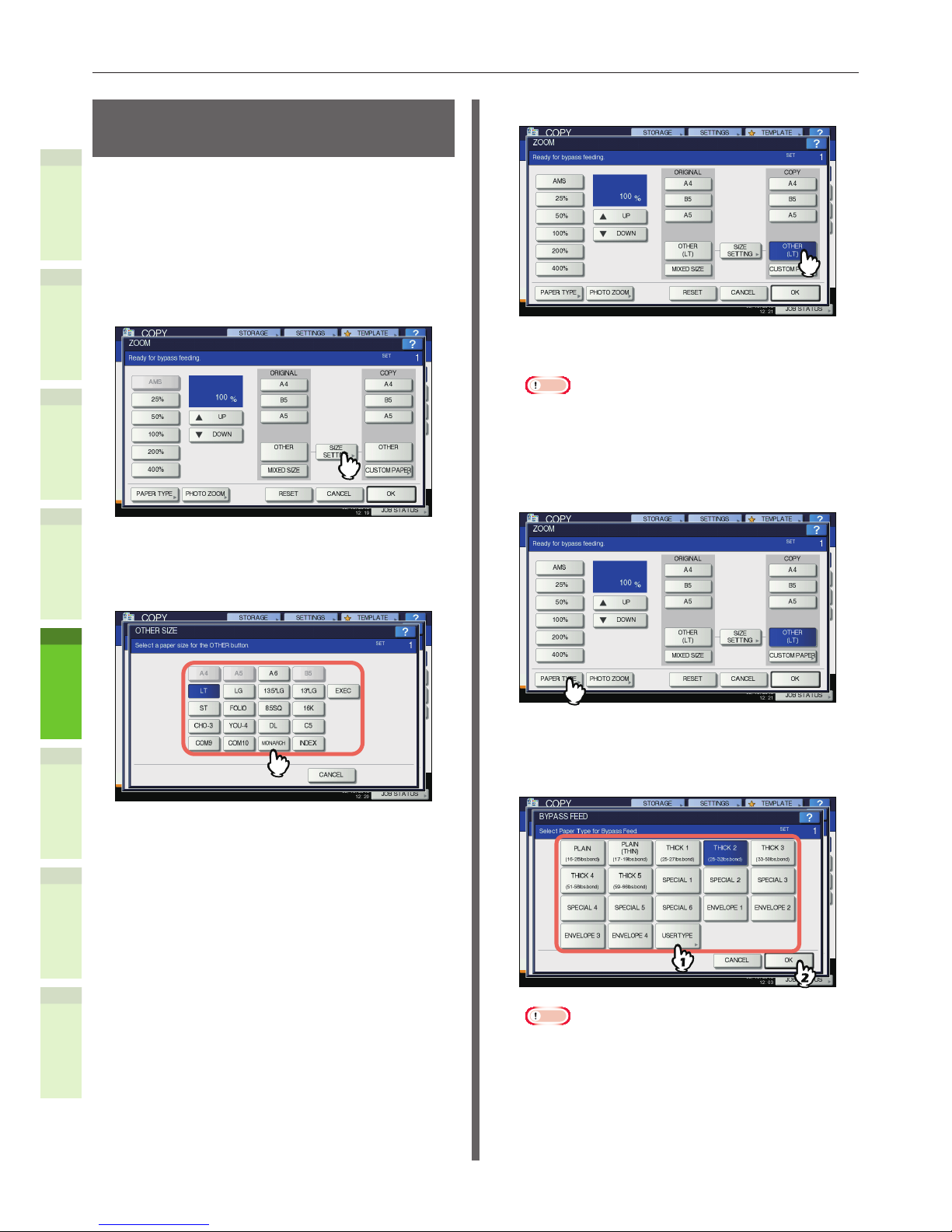
- 68 -
How to Load the Paper
1
2
4
5
6
3
Registering a Custom Size
(Undened Size)
When using custom sizes, congure the width
and length of the paper here.
1
Place the original(s) and paper.
& Basic Guide
2
Press [SIZE SETTING] on the touch
panel.
3
Press the button of the same size as
the paper you placed on the bypass
tray.
The selected size will be registered as an “OTHER”
size.
4
Press [OTHER] under “COPY”.
The paper size is now set to the one registered as
“OTHER” size.
Note
•
If the paper size is not selected in this step, copying
may be slowed down.
5
Press [PAPER TYPE] if the paper you
placed on the bypass tray is other
than plain paper.
6
Press the button of the same paper
type as the paper you placed on the
bypass tray. Then press [OK].
Note
•
If you select a wrong paper type, this could cause a
paper misfeed or signicant image trouble.
•
When you select a paper type, you can conrm it
with the icons displayed on the equipment status
indication area. For details, refer to the Basic Guide.

- 69 -
How to Load the Paper
1
2
4
5
6
3
7
After setting the paper size and
paper type, press [OK].
The menu returns to the BASIC menu.
8
Select other copy modes as
required, and then press the
[START] button on the control
panel.
About Auto Tray Switching
(Auto Tray Switch Function)
When a drawer or bypass tray runs out of paper
while printing, the machine locates another
drawer or bypass tray with the same size of
paper and begins feeding paper from that
drawer.
If an additional drawer unit has been installed,
up to 1460 pages can be continuously printed or
copied (A4 paper only).
Q Paper Switch Order.
When operating the automatic paper feed
funtion, the following order of priority for the
drawer or bypass tray is selected.
Memo
•
If you are loading non-conventional paper such as OHP
lm or labels in the bypass tray, the auto tray switch may
mistakenly use the wrong paper source. In this situation,
we recommend conguring paper other than plain paper in
advance.
When you are printing copies or
received faxes.
Drawer 1 Drawer 2 Drawer 3 Drawer 4
Bypass Tray
When you are printing from the
computer.
Starting from the drawer or bypass tray that is
currently being used, follow the settings of the
[Paper Source] of the printer driver.
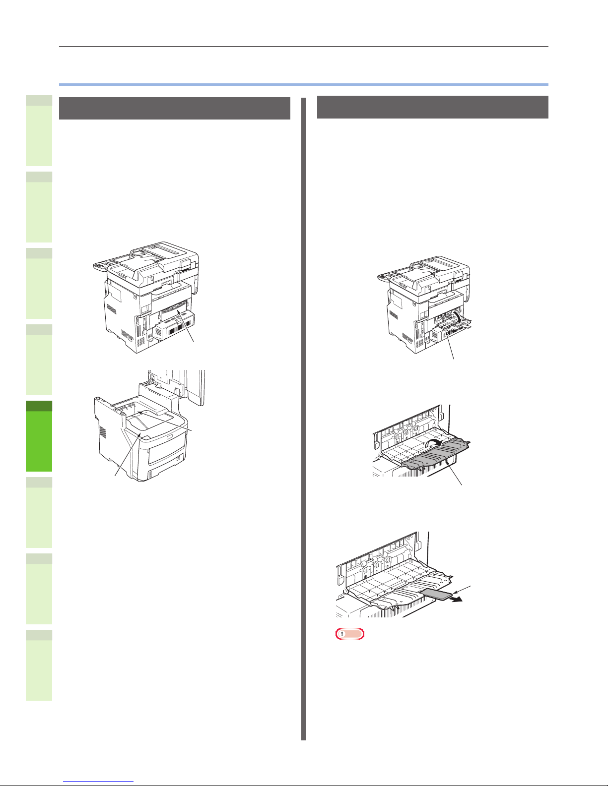
- 70 -
Paper Output
1
2
4
5
6
3
•
Paper Output
Using the Face Down Tray
Printed paper is delivered with the print side face
down, and stacked in the order printed.
Capacity of about 250 sheets at 82g/m
2
(ream
weight 70 kg).
1
Make sure that the face down tray at
the rear of the machine is closed.
Otherwise, printed paper will be
delivered to the face down tray.
Face Down Tray
Top Cover
Face Down Tray
Using the Face Up Tray
Printed paper such as A6 paper, postcards,
envelopes, labels, and OHP lm is delivered to
the face up tray.
Paper is delivered with the print side face up,
stacked opposite the order printed.
Capacity of about 100 sheets at 82g/m
2
(ream
weight 70 kg).
1
Pull open the face up tray at the rear
of the machine.
Face Up Tray
2
Fold out the face up tray.
Face Up Tray
3
Pull out the paper support.
Paper Support
Note
•
Printed paper is delivered to the face up tray.

1
2
4
5
6
3
5
About Document
Copies
About Document Copies …………………………… P.72
Loading Documents
………………………………… P.76

- 72 -
About Document Copies
1
2
4
5
6
3
•
About Document Copies
Document Conditions
You cannot load the following kinds of documents into the automatic document feed. Please use the
platen (glass surface).
•
Documents with tears or holes.
•
Documents that are creased or curled.
•
Wet documents.
•
Documents charged with static electricity.
•
Documents with a carbon on the back surface.
•
Cloth, metal sheets, or OHP lm.
•
Documents containing such things as staples,
clips, or tape.
•
Multipart documents or documents with glue
attached.
•
Shiny documents or documents with
unconventional coatings.
When placing a document on the platen (glass surface), avoid damaging the glass by following these
points.
•
Do not press the document against the platen with excessive force, especially when trying to copy a
thick document.
•
When using a hard object as the document, place it gently on the platen.
•
If the document has sharp edges, be careful not to scratch the glass.
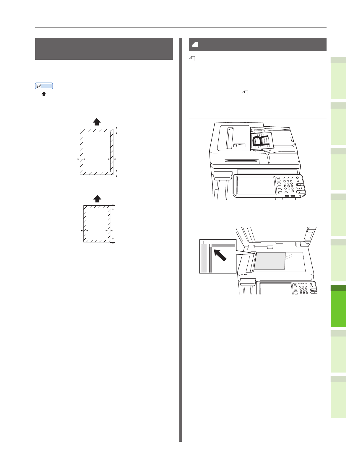
- 73 -
About Document Copies
1
2
4
5
6
3
Readable Areas of the
Document
Even characters in the gray area may be
unreadable.
Memo
•
This symbol indicates the direction of the automatic
document feed or the read start direction on the platen
(glass surface).
•
B4 Size
3.3mm3.3mm
Fax Send:
4.8mm
Copy/Scan:
1.8mm
Fax Send:
8.1mm
Copy/Scan:
5.1mm
B4 Size
•
A4 Size
2.8mm2.8mm
Fax Send:
4.8mm
Copy/Scan:
1.8mm
Fax Send:
7.4mm
Copy/Scan:
4.4mm
A4 Size
About Symbols
This symbol indicates horizontal placement of
the document when viewed from the front of the
machine. Documents are inserted from the short
side when using the automatic document feed.
Q Example: A4
When loading a document in the
automatic document feed.
When loading a document on the platen
(glass surface).
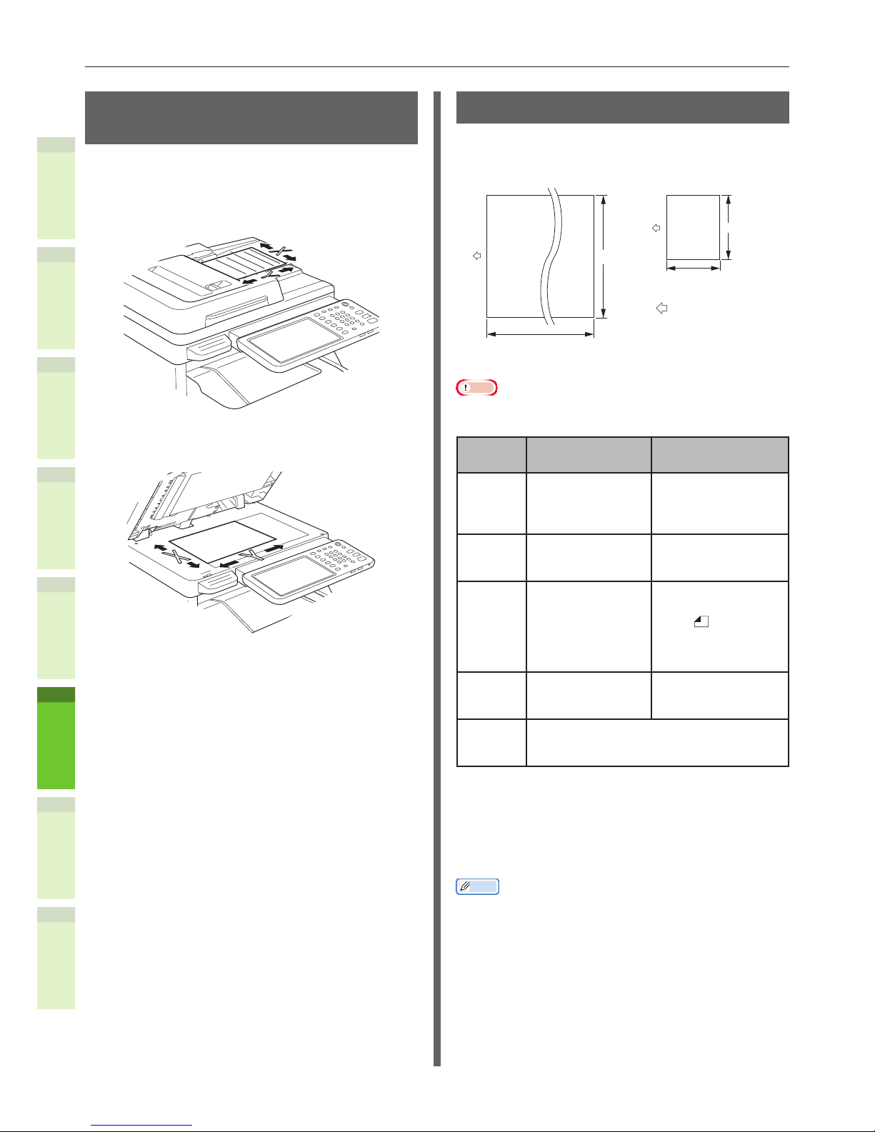
- 74 -
About Document Copies
1
2
4
5
6
3
The Width and Length of the
Document
When expressing the size of the document,
X represents the width of the paper and Y
represents its length.
•
Automatic Document Feed
•
Platen (Glass Surface)
Loadable Document Sizes
Q Document sizes for the automatic
document feed.
Maximum
Size
Send:900mm
Copy:450mm
Minimum
Size
128.5mm
Document delivery
direction
※
297mm
148.5mm
Note
•
The copy area is 432 mm (the remaining 18 mm cannot
be copied).
When reading
only one page.
Auto Continuous
Reading
Maximum Width 297 mm ×
length 900 mm
(When copying:
length: 450 mm)
Width 297 mm ×
length 432 mm
Minimum Width 148.5 mm ×
length 128.5 mm
Width 148.5 mm ×
length 128.5 mm
Single
Load
Number
*
1
─ A4/ letter (80g/m2)
:100 pages
legal ( ) :30 pages
A4/ letter (excluding
80g/m2), B5, A5,
half-letter:50 pages
Document
Paper
Thickness
42-128g/m
2
(0.05-0.15mm)
52-105g/m
2
(0.07-0.12mm)
Document
Paper
Quality
Equivalent high quality paper.
*
1
Sometimes the capacity of the memory may
be exceeded even if amount of loaded paper
does not exceed the load number indicated in
the previous table, depending of the content
of the document.
Memo
•
The paper thickness for newspapers is 0.05 to 0.06 and
for mailing postcards is 0.23 mm.
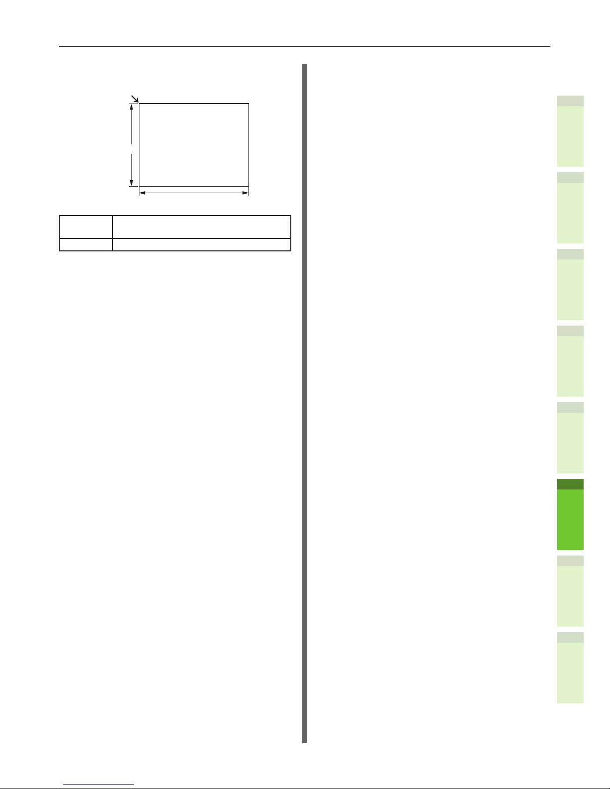
- 75 -
About Document Copies
1
2
4
5
6
3
Q Document Sizes for the Platen
(Glass Surface)
Maximum Size
215.9mm
355.6mm
Load Reference Position
Maximum Width 215.9mm (8.5”) × length
355.6mm (14”)
Minimum 20mm or less

- 76 -
Loading Documents
1
2
4
5
6
3
•
Loading Documents
Loading the Documents
Make sure that documents containing correction
uid, ink, and stamps are completely dry before
loading them.
CAUTION
•
For the duplex original, the original pops out
from the automatic document feed.
Do not put your hand on automatic
document feed.
Q When loading a document in the
automatic document feed.
1
Place the side of the document that
you want to copy face up in the
center of the holder.
2
Adjust the document guides to the
width of the document.
Document Guides
3
Gently insert the edges of the
documents so that they touch the
end of document feed.
Q When loading a document on the
platen (glass surface).
1
Open the document cover, place
the side of the document that you
want to copy face down, and align
the document to the load reference
position at the back-left side.
2
Gently close the document cover to
secure the document to the platen.

- 77 -
Loading Documents
1
2
4
5
6
3
Loading documents of various
sizes (mix documents).
When loading several documents with the same
width but different lengths, follow these points.
Memo
•
There are three ways in which you can load paper in sets.
•
A4 ( ) and A5 ( )
1
Adjust the document guides to the
width of the document.

1
2
4
5
6
3
6
Using Each
Function
Conguration of the Printer, Fax, and Scanner Functions.
………………………………………………………………………… P.79

- 79 -
Conguration of the Printer, Fax, and Scanner Functions
1
2
4
5
6
3
•
Conguration of the Printer, Fax, and Scanner Functions
To use the printer, fax, and scanner functions, congure the printer after installation in accordance with
the following ow chart. Conguration is not required for copy and scan to USB.
Configuration is completed.
Connecting via the USB
Install the printer drivers.
Connecting via the
network
Connecting via the
network
Configure the [Printer Mode]
Printer
Configuration is completed.
Fax
For Windows For Macintosh
Configure the IP address
in Windows
Configure the IP address
in the machine.
Install the printer drivers.
Determine the printing
method.
Configure the Macintosh
Install the printer drivers.
Configure the machine

- 80 -
Conguration of the Printer, Fax, and Scanner Functions
1
2
4
5
6
3
Configuration is completed.
Check the
settings of the
mail software.
Check the
settings of the
computer.
Scan To Mail
Scan To
Network PC
Scan To
Remote PC
Scan To
Local PC
Check the administrator password and IP
address of the machine.
Install the scanner drivers.
Configure the
email address
and mail servers
of the machine.
Configure the
computer that
saves the data.
Create the profile
of the machine.

1
2
4
5
6
3
Index

- 82 -
1
2
4
5
6
3
A
About Auto Tray Switching ......... 69
Adjusting the angle of the control
panel ................................... 19
Auto Tray Switch Function .......... 69
B
Bonjour printing ....................... 42
Bypass Tray ........................ 58, 64
C
Checking the copy operation ...... 48
Color Paper .............................. 56
Conguration Settings ............... 36
Conguring the Tray ................. 67
Connecting the Cables ............... 44
Custom Size ............................ 56
D
Dapartment Code ..................... 39
Department Code ..................... 36
[Device Settings] tab ................ 37
Document
About Symbols ................... 73
automatic document feed .... 72
glass surface ..................... 72
Readable Areas of the
Document ....................... 73
Width and Length ............... 74
Document set
automatic document feed
................................ 73, 76
document feed ................... 74
document sizes .................. 74
glass surface ................75, 76
mix documents .................. 77
Drawers ..................37, 41, 42, 43
E
[ENERGY SAVER] button ............ 53
Envelope ................................. 56
F
Face Down Tray ........................ 70
Face Up Tray ............................ 70
Finisher .............................. 37, 40
G
Glass Surface
Document Conditions .......... 72
Document direction ............ 73
Loading Documents .......74, 76
I
Index Card .............................. 56
Installation Conditions ............... 25
Installing ................................. 27
Installing Additional Tray Units ... 33
IPP printing ............................. 41
L
Label ...................................... 56
LPR printing ............................. 40
M
mix documents ........................ 77
Multi-operational ...................... 21
N
Name and Function of Each Part
Machine ............................ 16
Operator Panel ................... 18
Network Cables ........................ 44
O
Output method......................... 58
Override Application Paper Source
Settings ................................ 38
P
Paper size dial .......................... 63
Paper source ............................ 58
Paper Thickness ....................... 67
Paper Type .............................. 67
Partly-Printing Paper ................. 56
Plain Paper .............................. 56
Power
OFF .................................. 52
ON ................................... 51
Power Save Mode ............... 53
Power Save Mode ..................... 53
PPD ........................................ 39
Precautions about the Power Supply
........................................... 50
Printable Areas ......................... 60
R
Readable Areas of the Document
........................................... 73
Registering a Custom Size ......... 68
S
Setting letters .......................... 22
Setting Up the Printer ............... 36
Simultaneous Functions ............. 21
Supply .................................... 23
T
Telephone line .......................... 45
Test Printing ............................ 48
U
Undened Size ......................... 68
Unpacking ............................... 27
USB cable ................................ 44

©2012 TOSHIBA TEC CORPORATION All rights reserved
Under the copyright laws, this manual cannot be reproduced in any form without prior written permission of TTEC.

1-11-1, OHSAKI, SHINAGAWA-KU, TOKYO, JAPAN
MULTIFUNCTIONAL DIGITAL COLOR SYSTEMS
User’s Manual Setup Guide
©2012 TOSHIBA TEC CORPORATION All rights reserved
R121220M7500-TTEC
Ver00 F 2012-12
FC-287CS/347CS/407CS
OME12026700
 Loading...