


 Loading...
SERVICE MANUAL
MULTIFUNCTIONAL DIGITAL SYSTEMS
e-STUDIO182/212/242
Model: DP1830/DP2120/DP2420
Publish Date: December 2009
File No. SME09001500
R091021I2800-TTEC
Ver00_2009-12

Trademarks
•The official name of Windows 95 is Microsoft Windows 95 Operating System.
•The official name of Windows 98 is Microsoft Windows 98 Operating System.
•The official name of Windows Me is Microsoft Windows Millennium Edition Operating System.
•The official name of Windows 2000 is Microsoft Windows 2000 Operating System.
•The official name of Windows XP is Microsoft Windows XP Operating System.
•Microsoft, Windows, Windows NT, Windows Vista and the brand names and product names of other Microsoft products are trademarks or registered trademarks of Microsoft Corporation in the U.S. and/or other countries.
•Apple, AppleTalk, Macintosh, and Mac are trademarks of Apple Computer, Inc. in the U.S. and other countries.
•PostScript is a trademark of Adobe Systems Incorporated.
•NOVELL, NetWare, and NDS are trademarks or registered trademarks of Novell, Inc.
•Mylar is a registered trademark of DuPont Teijin Films U.S. Limited Partnership.
•Molykote is a registered trademark of Dow Corning Corporation.
•FLOIL is a registrated treadmark of Kanto Kasei Ltd. CORPORATION.
•TopAccess is a trademark of Toshiba Tec Corporation.
•iCLASS is a trademark of HID Corporation.
•MIFARE is a trademark of Royal Philips Electronics.
•Other company names and product names in this manual are the trademarks of their respective companies.
© 2009 TOSHIBA TEC CORPORATION All rights reserved
Under the copyright laws, this manual cannot be reproduced in any form without prior written permission of TOSHIBA TEC CORPORATION. No patent liability is assumed, however, with respect to the use of the information contained herein.
GENERAL PRECAUTIONS REGARDING THE SERVICE FOR e-STUDIO182/212/242
The installation and service should be done by a qualified service technician.
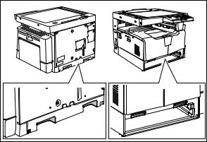
1)Transportation/Installation
-When transporting/installing the equipment, remove the drawer, employ two persons and be sure to hold the positions as shown in the figure.
The equipment is quite heavy and weighs approximately 33 kg (72.75 lb), therefore pay full attention when handling it.
-Be sure not to hold the movable parts or units (e.g. the control panel, ADU or RADF) when transporting the equipment.
-Be sure to use a dedicated outlet with AC 110 V / 13.2 A, 115 V or 127 V / 12 A, 220-240 V or 240 V / 8 A for its power source.
-The equipment must be grounded for safety.
-Select a suitable place for installation. Avoid excessive heat, high humidity, dust, vibration and direct sunlight.
-Provide proper ventilation since the equipment emits a slight amount of ozone.
-To insure adequate working space for the copying operation, keep a minimum clearance of 80 cm (32”) on the left, 80 cm (32”) on the right and 10 cm (4”) on the rear.
-The equipment shall be installed near the socket outlet and shall be easily accessible.
-Be sure to fix and plug in the power cable securely after the installation so that no one trips over it.
-When the equipment is used after the option is removed, be sure to install the parts or the covers which have been taken off so that the inside of the equipment is not exposed.
2)General Precautions at Service
-Be sure to turn the power OFF and unplug the power cable during service (except for the service should be done with the power turned ON).
-Unplug the power cable and clean the area around the prongs of the plug and socket outlet once a year or more. A fire may occur when dust lies on this area.
-When the parts are disassembled, reassembly is the reverse of disassembly unless otherwise noted in this manual or other related documents. Be careful not to install small parts such as screws, washers, pins, E-rings, star washers in the wrong places.
-Basically, the equipment should not be operated with any parts removed or disassembled.
-The PC board must be stored in an anti-electrostatic bag and handled carefully using a wristband since the ICs on it may be damaged due to static electricity.
Caution: Before using the wristband, unplug the power cable of the equipment and make sure that there are no charged objects which are not insulated in the vicinity.
-Avoid expose to laser beam during service. This equipment uses a laser diode. Be sure not to expose your eyes to the laser beam. Do not insert reflecting parts or tools such as a screwdriver on the laser beam path. Remove all reflecting metals such as watches, rings, etc. before starting service.
-Be sure not to touch high-temperature sections such as the exposure lamp, fuser unit, damp heater and areas around them.
-Be sure not to touch high-voltage sections such as the chargers, developer, high-voltage transformer and power supply unit. Especially, the board of these components should not be touched since the electric charge may remain in the capacitors, etc. on them even after the power is turned OFF.
-Make sure that the equipment will not operate before touching potentially dangerous places (e.g. rotating/operating sections such as gears, belts pulleys, fans and laser beam exit of the laser optical unit).
-Be careful when removing the covers since there might be the parts with very sharp edges underneath.
-When servicing the equipment with the power turned ON, be sure not to touch live sections and rotating/operating sections. Avoid exposing your eyes to laser beam.
-Use designated jigs and tools.
-Use recommended measuring instruments or equivalents.
-Return the equipment to the original state and check the operation when the service is finished.
3)Important Service Parts for Safety
-The breaker, door switch, fuse, thermostat, thermofuse, thermistor, batteries, IC-RAMs including lithium batteries, etc. are particularly important for safety. Be sure to handle/install them properly. If these parts are short-circuited and their functions become ineffective, they may result in fatal accidents such as burnout. Do not allow a short-circuit and/or do not use the parts not recommended by Toshiba TEC Corporation.

4)Cautionary Labels
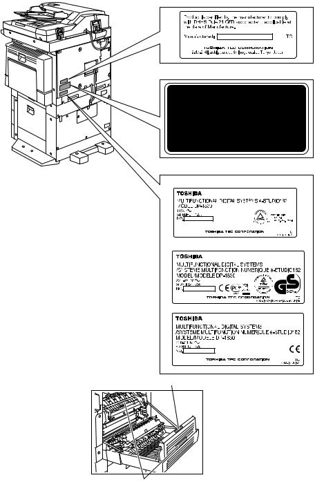
-During servicing, be sure to check the rating plate and cautionary labels such as “Unplug the power cable during service”, “CAUTION. HOT”, “CAUTION. HIGH VOLTAGE”, “CAUTION. LASER BEAM”, etc. to see if there is any dirt on their surface and if they are properly stuck to the equipment.
Certification label (For UC)
Explanatory label
Identification label
For UC
For EU
For others
Warning for high-temperature areas (ventilation holes)
Warning for high-temperature areas (fuser unit)

5)Disposal of the Equipment, Supplies, Packing Materials, Used Batteries and IC-RAMs
-Regarding the recovery and disposal of the equipment, supplies, packing materials, used batteries and IC-RAMs including lithium batteries, follow the relevant local regulations or rules.
Caution:
Dispose of used batteries and IC-RAMs including lithium batteries according to this manual.
Attention:
Se débarrasser de batteries et IC-RAMs usés y compris les batteries en lithium selon ce manuel.
Vorsicht:
Entsorgung der gebrauchten Batterien und IC-RAMs (inclusive der Lithium-Batterie) nach diesem Handbuch.

ALLEGEMEINE SICHERHEITSMASSNAHMEN IN BEZUG AUF DIE WARTUNG FÜR e-STUDIO182/212/242
Die Installation und die Wartung sind von einem qualifizierten ServiceTechniker durchzuführen.
1)Transport/Installation
-Zum Transportieren/Installieren des Gerätes werden 2 Personen benötigt. Die Kassette zuerst herausnehmen und nur an den in der Abbildung gezeigten Stellen tragen.
Das Gerät ist sehr schwer und wiegt etwa 33 kg; deshalb muss bei der Handhabung des Geräts besonders aufgepasst werden.
-Beim Transportieren des Geräts nicht an den beweglichen Teilen oder Einheiten halten.
-Eine spezielle Steckdose mit Stromversorgung von AC 110 V / 13.2 A, 115 V oder 127 V / 12 A, 220-240 V / 8 A als Stromquelle verwenden.
-Das Gerät ist aus Sicherheitsgründen zu erden.
-Einen geeigneten Standort für die Installation wählen. Standorte mit zuviel Hitze, hoher Luftfeuchtigkeit, Staub, Vibrieren und direkter Sonneneinstrahlung sind zu vermeiden.
-Für ausreichende Belüftung sorgen, da das Gerät etwas Ozon abgibt.
-Um einen optimalen Kopierbetrieb zu gewährleisten, muss ein Abstand von mindestens 80 cm links, 80 cm rechts und 10 cm dahinter eingehalten werden.
-Das Gerät ist in der Nähe der Steckdose zu installieren; diese muss leicht zu erreichen sein.
-Nach der Installation muss das Netzkabel richtig hineingesteckt und befestigt werden, damit niemand darüber stolpern kann.
2)Allgemeine Sicherheitsmassnahmen in bezug auf die Wartung
-Während der Wartung das Gerät ausschalten und das Netzkabel herausziehen (ausser Wartung, die bei einem eingeschalteten Gerät, durchgeführt werden muss).
-Das Netzkabel herausziehen und den Bereich um die Steckerpole und die Steckdose die Umgebung in der Nähe von den Steckerzacken und der Steckdose wenigstens einmal im Jahr reinigen. Wenn Staub sich in dieser Gegend ansammelt, kann dies ein Feuer verursachen.
-Wenn die Teile auseinandergenommen werden, wenn nicht anders in diesem Handbuch usw erklärt, ist das Zusammenbauen in umgekehrter Reihenfolge durchzuführen. Aufpassen, dass kleine Teile wie Schrauben, Dichtungsringe, Bolzen, E-Ringe, Stern-Dichtungsringe, Kabelbäume nicht an den verkehrten Stellen eingebaut werden.
-Grundsätzlich darf das Gerät mit enfernten oder auseinandergenommenen Teilen nicht in Betrieb genommen werden.
-Das PC-Board muss in einer Anti-elektrostatischen Hülle gelagert werden. Nur Mit einer Manschette bei Betätigung eines Armbandes anfassen, sonst könnte es sein, dass die integrierten Schaltkreise durch statische Elektrizität beschädigt werden.
Vorsicht: Vor Benutzung der Manschette der Betätigung des Armbandes, das Netzkabel des Gerätes herausziehen und prüfen, dass es in der Nähe keine geladenen Gegenstände, die nicht isoliert sind, gibt.
-Setzen Sie sich während der Wartungsarbeiten nicht dem Laserstrahl aus. Dieses Gerät ist mit einer Laserdiode ausgestattet. Es ist unbedingt zu vermeiden, direkt in den Laserstrahl zu blicken. Keine reflektierenden Teile oder Werkzeuge, wie z. B. Schraubendreher, in den Pfad des Laserstrahls halten. Vor den Wartungsarbeiten sämtliche reflektierenden Metallgegenstände, wie Uhren, Ringe usw., entfernen.
-Auf keinen Fall Hochtemperaturbereiche, wie die Belichtungslampe, die Fixiereinheit, die Heizquelle und die umliegenden Bereiche, berühren.
-Auf keinen Fall Hochspannungsbereiche, wie die Ladeeinheiten, die Entwicklereinheit, den Hochspannungstransformator, und das Netzgerät, berühren. Insbesondere sollten die Platinen dieser Komponenten nicht berührt werden, da die Kondensatoren usw. auch nach dem Ausschalten des Geräts noch elektrisch geladen sein können.
-Vor dem Berühren potenziell gefährlicher Bereiche (z. B. drehbare oder betriebsrelevante Bereiche, wie Zahnräder, Riemen, Riemenscheiben, Lüfter und die Laseraustrittsöffnung der optischen Lasereinheit) sicherstellen, dass das Gerät sich nicht bedienen lässt.
-Beim Entfernen von Abdeckungen vorsichtig vorgehen, da sich darunter scharfkantige Komponenten befinden können.
-Bei Wartungsarbeiten am eingeschalteten Gerät dürfen keine unter Strom stehenden, drehbaren oder betriebsrelevanten Bereiche berührt werden. Nicht direkt in den Laserstrahl blicken.
-Ausschließlich vorgesehene Werkzeuge und Hilfsmittel verwenden.
-Empfohlene oder gleichwertige Messgeräte verwenden.
-Nach Abschluss der Wartungsarbeiten das Gerät in den ursprünglichen Zustand zurück versetzen und den einwandfreien Betrieb überprüfen.
3)Sicherheitsrelevante Wartungsteile
-Der Leistungsschutzschalter, der Türschalter, die Sicherung, der Thermostat, die Thermosicherung, der Thermistor, die IC-RAMs einschließlich der Lithiumakkus usw. sind besonders sicherheitsrelevant. Sie müssen unbedingt korrekt gehandhabt und installiert werden. Wenn diese Teile kurzgeschlossen und funktionsunfähig werden, kann dies zu schwerwiegenden Schäden, wie einem Abbrand, führen. Kurzschlüsse sind zu vermeiden, und es sind ausschließlich Teile zu verwenden, die von der Toshiba TEC Corporation empfohlen sind.
4)Warnetiketten
-Im Rahmen der Wartung unbedingt das Leistungsschild und die Etiketten mit Warnhinweisen überprüfen [z. B. „Unplug the power cable during service“ („Netzkabel vor Beginn der Wartungsarbeiten abziehen“), „CAUTION. HOT“ („VORSICHT, HEISS“), „CAUTION. HIGH VOLTAGE“ („VORSICHT, HOCHSPANNUNG“), „CAUTION. LASER BEAM“ („VORSICHT, LASER“) usw.], um sicherzustellen, dass sie nicht verschmutzt sind und korrekt am Gerät angebracht sind.
Certification label (For UC)
Explanatory label
Identification label
For UC
For EU
For others
Warning for high-temperature areas (ventilation holes)
Warning for high-temperature areas (fuser unit)

5)Entsorgung des Geräts, der Verbrauchsund Verpackungsmaterialien, alter Akkus und IC-RAMs
-In Bezug auf die Entsorgung und Wiederverwertung des Geräts, der Verbrauchsund Verpackungsmaterialien, alter Akkus und IC-RAMs, einschließlich Lithiumakkus, sind die einschlägigen nationalen oder regionalen Vorschriften zu befolgen.
Caution:
Dispose of used batteries and IC-RAMs including lithium batteries according to this manual.
Attention:
Se débarrasser de batteries et IC-RAMs usés y compris les batteries en lithium selon ce manuel.
Vorsicht:
Entsorgung der gebrauchten Batterien und IC-RAMs (inclusive der Lithium-Batterie) nach diesem Handbuch.
•Laseremissionseinheit
Diese Einheit besteht aus der Laserdiode, dem Fokussierungsobjektiv, der Blende und dem Zylinderobjektiv.
-Laserdiode
Diese Laserdiode zeichnet sich durch eine geringe Regeldifferenz, eine kleine Laservariation und einen niedrigen Schwellenstrom aus.
Die Blende der Laseremissionseinheit ist unter dem Fokussierobjektiv angeordnet, um die Form der Laserstrahlen in der primären und sekundären Scanrichtung festzulegen.
Die Laserdiode gibt Laserstrahlen als Reaktion auf die Signale der Laseremissionssteuerung (ein/ aus) von der Lasertreiber-PC-Platine (LDR) aus. Die durch das Fokussierobjektiv geführten Laserstrahlen werden auf die Trommeloberfläche fokussiert.
-Vorsichtsmaßnahmen im Zusammenhang mit Lasern
Dieses Gerät enthält eine Laserdiode, die einen unsichtbaren Laserstrahl emittiert.
Da man diesen Laserstrahl nicht sehen kann, ist bei der Handhabung der Komponenten der optischen Lasereinheit, bei der Durchführung von Arbeiten und bei der Justierung des Laserstrahls äußerste Vorsicht geboten. Arbeiten dürfen niemals anhand anderer als den vorgeschriebenen Anleitungen durchgeführt werden; andernfalls kann es zu einer Schädigung Exposition durch Laserstrahlung kommen.
Die Lasereinheit ist vollständig mit einer Schutzabdeckung versiegelt. Solange ausschließlich die Arbeitsschritte der vorgeschriebenen Anleitungen durchgeführt werden, tritt der Laserstrahl nicht aus, und es besteht keine Gefahr, der Laserstrahlung ausgesetzt zu werden.
Das folgende Laser-Warnetikett ist an der Abdeckung vorne rechts angebracht.
•Warnhinweise:
-Setzen Sie sich während der Wartungsarbeiten nicht dem Laserstrahl aus.
Dieses Gerät ist mit einer Laserdiode ausgestattet. Es ist unbedingt zu vermeiden, direkt in den Laserstrahl zu blicken. Keine reflektierenden Teile oder Werkzeuge, wie z. B. Schraubendreher, in den Pfad des Laserstrahls halten. Vor den Wartungsarbeiten sämtliche reflektierenden Metallgegenstände, wie Uhren, Ringe usw., entfernen.
-Bei Wartungsarbeiten am eingeschalteten Gerät dürfen keine unter Strom stehenden, drehbaren oder betriebsrelevanten Bereiche berührt werden. Nicht direkt in den Laserstrahl blicken.
-Im Rahmen der Wartung unbedingt das Leistungsschild und die Etiketten mit Warnhinweisen überprüfen [z. B. „Unplug the power cable during service“ („Netzkabel vor Beginn der Wartungsarbeiten abziehen“), „CAUTION. HOT“ („VORSICHT, HEISS“), „CAUTION. HIGH VOLTAGE“ („VORSICHT, HOCHSPANNUNG“), „CAUTION. LASER BEAM“ („VORSICHT, LASER“) usw.], um sicherzustellen, dass sie nicht verschmutzt sind und korrekt am Gerät angebracht sind.
CONTENTS
1. SPECIFICATIONS / ACCESSORIES / OPTIONS / SUPPLIES ................................... |
1-1 |
|
1.1 |
Specifications .................................................................................................................... |
1-1 |
1.2 |
Accessories....................................................................................................................... |
1-5 |
1.3 |
Options.............................................................................................................................. |
1-6 |
1.4 |
Supplies ............................................................................................................................ |
1-7 |
1.5 |
System List........................................................................................................................ |
1-8 |
2. OUTLINE OF THE MACHINE ....................................................................................... |
2-1 |
||
2.1 |
Sectional View................................................................................................................... |
2-1 |
|
2.2 |
Electric Parts Layout ......................................................................................................... |
2-4 |
|
2.3 |
Symbols and Functions of Various Components ............................................................ |
2-11 |
|
2.4 |
General Description ........................................................................................................ |
2-15 |
|
|
2.4.1 |
System block diagram ..................................................................................... |
2-15 |
|
2.4.2 |
Construction of boards..................................................................................... |
2-16 |
2.5 |
Disassembly and Replacement of Covers ...................................................................... |
2-18 |
|
|
2.5.1 |
Front cover....................................................................................................... |
2-18 |
|
2.5.2 |
Inner tray.......................................................................................................... |
2-18 |
|
2.5.3 |
Left cover ......................................................................................................... |
2-18 |
|
2.5.4 |
Tray rear cover ................................................................................................ |
2-19 |
|
2.5.5 |
Front right cover............................................................................................... |
2-19 |
|
2.5.6 |
Front upper cover ............................................................................................ |
2-19 |
|
2.5.7 |
ADU cover ....................................................................................................... |
2-20 |
|
2.5.8 |
Right front cover .............................................................................................. |
2-20 |
|
2.5.9 |
Right rear cover ............................................................................................... |
2-21 |
|
2.5.10 |
Rear cover ....................................................................................................... |
2-21 |
2.6 |
Disassembly and Replacement of PC boards................................................................. |
2-22 |
|
|
2.6.1 |
MAIN board (MAIN) ......................................................................................... |
2-22 |
|
2.6.2 |
SRAM board (SRAM) ...................................................................................... |
2-23 |
|
2.6.3 |
Fuse PC board (FUS) ...................................................................................... |
2-23 |
|
2.6.4 |
Paper feed controller PC board (PFC)............................................................. |
2-24 |
|
2.6.5 |
Switching regulator unit (PS) ........................................................................... |
2-25 |
|
2.6.6 |
Switching regulator cooling fan (M6) ............................................................... |
2-27 |
2.7 |
Removal and Installation of Options ............................................................................... |
2-28 |
|
|
2.7.1 |
MR-2020 (Automatic Document Feeder (ADF))/ |
|
|
|
MR-3023 (Reversing Automatic Document Feeder (RADF)) .......................... |
2-28 |
|
2.7.2 |
MY-1027 (Paper Feed Unit (PFU)) .................................................................. |
2-30 |
|
2.7.3 |
KD-1022 (Paper Feed Pedestal (PFP)) ........................................................... |
2-35 |
3. COPY PROCESS .......................................................................................................... |
3-1 |
|
3.1 |
General Description of Copying Process .......................................................................... |
3-1 |
3.2 |
Details of Copying Process ............................................................................................... |
3-2 |
3.3 |
Comparison with e-STUDIO230/280............................................................................... |
3-13 |
4. GENERAL OPERATION............................................................................................... |
4-1 |
||
4.1 |
Overview of Operation ...................................................................................................... |
4-1 |
|
4.2 |
Description of Operation ................................................................................................... |
4-2 |
|
|
4.2.1 |
Warming-up ....................................................................................................... |
4-2 |
|
4.2.2 |
Ready state (ready for copying)......................................................................... |
4-2 |
|
4.2.3 |
Drawer feed copying.......................................................................................... |
4-3 |
|
4.2.4 |
Bypass feed copying.......................................................................................... |
4-4 |
|
4.2.5 |
Interruption copying ........................................................................................... |
4-4 |
4.3 |
Detection of Abnormality ................................................................................................... |
4-5 |
|
|
4.3.1 |
Types of abnormality ......................................................................................... |
4-5 |
|
4.3.2 |
Description of abnormality ................................................................................. |
4-6 |
5. CONTROL PANEL........................................................................................................ |
5-1 |
5.1 General Description ......................................................................................................... |
5-1 |
© 2009 TOSHIBA TEC CORPORATION All rights reserved |
e-STUDIO182/212/242 |
|
CONTENTS |
1
|
5.2 |
Items Shown on the Display Panel ................................................................................... |
|
5-2 |
|
|
|
5.2.1 |
Display ............................................................................................................... |
|
5-2 |
|
|
5.2.2 |
Message ............................................................................................................ |
|
5-3 |
|
5.3 |
Relation between Equipment State and Operation ........................................................... |
|
5-4 |
|
|
5.4 |
Operation .......................................................................................................................... |
|
5-5 |
|
|
|
5.4.1 |
Block diagram .................................................................................................... |
|
5-5 |
|
|
5.4.2 |
LED display circuit ............................................................................................. |
|
5-6 |
|
5.5 |
Disassembly and Replacement......................................................................................... |
|
5-7 |
|
|
|
5.5.1 |
Control panel unit............................................................................................... |
|
5-7 |
|
|
5.5.2 |
Control panel PC board (HPNL) ........................................................................ |
|
5-7 |
|
|
5.5.3 |
LCD PC board (LCD)......................................................................................... |
|
5-8 |
6. |
SCANNER ..................................................................................................................... |
|
|
6-1 |
|
|
6.1 |
General Description .......................................................................................................... |
|
6-1 |
|
|
6.2 |
Construction ...................................................................................................................... |
|
6-2 |
|
|
6.3 |
Functions........................................................................................................................... |
|
6-3 |
|
|
6.4 |
Description of Operation ................................................................................................... |
|
6-5 |
|
|
|
6.4.1 |
Scanning operation............................................................................................ |
|
6-5 |
|
|
6.4.2 |
Scan motor drive circuit ..................................................................................... |
|
6-6 |
|
6.5 |
Contact Image Sensor Unit Control Circuit ....................................................................... |
|
6-8 |
|
|
|
6.5.1 |
Exposure LED control circuit ............................................................................. |
|
6-8 |
|
|
6.5.2 |
CCD control circuit............................................................................................. |
|
6-9 |
|
6.6 |
Automatic Original Size Detection Circuit ....................................................................... |
|
6-11 |
|
|
|
6.6.1 |
Principle of original size detection ................................................................... |
|
6-11 |
|
|
6.6.2 |
Process of detection of original size ................................................................ |
|
6-12 |
|
6.7 |
Disassembly and Replacement....................................................................................... |
|
6-16 |
|
|
|
6.7.1 |
Original glass ................................................................................................... |
|
6-16 |
|
|
6.7.2 |
Scanner top cover............................................................................................ |
|
6-17 |
|
|
6.7.3 |
Automatic original detection sensor (APS sensor) .......................................... |
6-18 |
|
|
|
6.7.4 |
Scan motor (M1) .............................................................................................. |
|
6-18 |
|
|
6.7.5 |
CIS home position sensor (S1)........................................................................ |
|
6-20 |
|
|
6.7.6 |
Platen sensor (S2) ........................................................................................... |
|
6-20 |
|
|
6.7.7 |
CIS unit (CIS)................................................................................................... |
|
6-21 |
|
|
6.7.8 |
CIS case .......................................................................................................... |
|
6-23 |
|
|
6.7.9 |
CIS unit drive belt-1 ........................................................................................ |
|
6-24 |
|
|
6.7.10 |
CIS unit drive belt-2 ......................................................................................... |
|
6-25 |
7. |
LASER OPTICAL UNIT ................................................................................................ |
|
7-1 |
||
|
7.1 |
General Description .......................................................................................................... |
|
7-1 |
|
|
7.2 |
Structure............................................................................................................................ |
|
|
7-2 |
|
7.3 |
Laser Diode Control Circuit ............................................................................................... |
|
7-5 |
|
|
7.4 |
Polygonal Motor Control Circuit ........................................................................................ |
|
7-6 |
|
|
7.5 |
Disassembly and Replacement......................................................................................... |
|
7-7 |
|
|
|
7.5.1 |
Laser optical unit................................................................................................ |
|
7-7 |
8. |
DRIVE UNIT .................................................................................................................. |
|
|
8-1 |
|
|
8.1 |
General Description .......................................................................................................... |
|
8-1 |
|
|
8.2 |
Configuration..................................................................................................................... |
|
8-2 |
|
|
8.3 |
Functions .......................................................................................................................... |
|
8-3 |
|
|
8.4 |
Main Motor Control Circuit ................................................................................................ |
|
8-4 |
|
|
8.5 |
Disassembly and Replacement......................................................................................... |
|
8-6 |
|
|
|
8.5.1 |
Main motor (M3) ................................................................................................ |
|
8-6 |
|
|
8.5.2 |
Toner motor (M2)............................................................................................... |
|
8-6 |
|
|
8.5.3 |
Main motor drive unit ......................................................................................... |
|
8-7 |
9. |
PAPER FEEDING SYSTEM.......................................................................................... |
|
9-1 |
||
|
9.1 |
General Description .......................................................................................................... |
|
9-1 |
|
|
9.2 |
Configuration..................................................................................................................... |
|
9-2 |
|
|
9.3 |
Functions........................................................................................................................... |
|
9-3 |
|
|
9.4 |
Operation .......................................................................................................................... |
|
9-5 |
|
e-STUDIO182/212/242 |
|
© 2009 TOSHIBA TEC CORPORATION All rights reserved |
|||
CONTENTS |
|
|
|
|
|
2
9.4.1 |
Drawer ............................................................................................................... |
9-5 |
9.4.2 |
Bypass tray ........................................................................................................ |
9-7 |
9.4.3 |
General operation .............................................................................................. |
9-9 |
9.5 Disassembly and Replacement....................................................................................... |
9-10 |
|
9.5.1 |
Bypass unit ...................................................................................................... |
9-10 |
9.5.2 |
Bypass tray ...................................................................................................... |
9-11 |
9.5.3 |
Bypass separation pad ................................................................................... |
9-11 |
9.5.4 |
Bypass roller unit ............................................................................................. |
9-12 |
9.5.5 |
Bypass pickup roller ........................................................................................ |
9-14 |
9.5.6 |
Bypass feed roller ........................................................................................... |
9-14 |
9.5.7 |
Bypass paper sensor (S8) ............................................................................... |
9-14 |
9.5.8 |
Bypass pickup solenoid (SOL2)....................................................................... |
9-15 |
9.5.9 |
Bypass pickup clutch / Bypass feed clutch ...................................................... |
9-16 |
9.5.10 |
Damp heater unit (DH3) / Dummy plate .......................................................... |
9-18 |
9.5.11 |
Paper empty sensor (S7)................................................................................. |
9-18 |
9.5.12 |
Pickup roller .................................................................................................... |
9-19 |
9.5.13 |
Registration clutch (CLT1) ............................................................................... |
9-20 |
9.5.14 |
Pickup solenoid (SOL1) ................................................................................... |
9-20 |
9.5.15 |
Drawer pickup clutch ....................................................................................... |
9-21 |
9.5.16 |
Registration roller (rubber)............................................................................... |
9-22 |
9.5.17 |
Registration roller (metal) ................................................................................ |
9-23 |
9.5.18 |
Feed gear unit.................................................................................................. |
9-24 |
9.5.19 |
Drawer detection switch (SW5) ....................................................................... |
9-24 |
9.5.20 |
Registration sensor (S4) .................................................................................. |
9-25 |
10. DRUM RELATED SECTION ....................................................................................... |
10-1 |
||
10.1 |
General Description ........................................................................................................ |
10-1 |
|
10.2 |
Configuration................................................................................................................... |
10-2 |
|
10.3 |
Functions......................................................................................................................... |
10-3 |
|
10.4 |
High-Voltage Output Control Circuit................................................................................ |
10-5 |
|
|
10.4.1 |
General description.......................................................................................... |
10-5 |
|
10.4.2 |
Description of Operation .................................................................................. |
10-6 |
10.5 |
Drum Temperature Detection Circuit .............................................................................. |
10-7 |
|
|
10.5.1 |
General description.......................................................................................... |
10-7 |
|
10.5.2 |
Circuit configuration ......................................................................................... |
10-7 |
10.6 |
Temperature/Humidity Detection Circuit ......................................................................... |
10-8 |
|
|
10.6.1 |
General Description ......................................................................................... |
10-8 |
|
10.6.2 |
Circuit configuration ......................................................................................... |
10-8 |
10.7 |
Disassembly and Replacement....................................................................................... |
10-9 |
|
|
10.7.1 |
Process unit ..................................................................................................... |
10-9 |
|
10.7.2 |
Drum cleaner unit .......................................................................................... |
10-11 |
|
10.7.3 |
Discharge LED (ERS).................................................................................... |
10-12 |
|
10.7.4 |
Main charger.................................................................................................. |
10-13 |
|
10.7.5 |
Main charger grid .......................................................................................... |
10-13 |
|
10.7.6 |
Main charger cleaner ..................................................................................... |
10-14 |
|
10.7.7 |
Needle electrode ........................................................................................... |
10-14 |
|
10.7.8 |
Drum ............................................................................................................. |
10-15 |
|
10.7.9 |
Drum cleaning blade ..................................................................................... |
10-15 |
|
10.7.10 |
Drum separation finger ................................................................................. |
10-15 |
|
10.7.11 |
Recovery blade ............................................................................................. |
10-16 |
|
10.7.12 |
Transfer/Separation charger.......................................................................... |
10-16 |
|
10.7.13 |
Charger wire ................................................................................................. |
10-17 |
|
10.7.14 |
Transfer unit................................................................................................... |
10-18 |
|
10.7.15 |
Ozone filter ................................................................................................... |
10-19 |
|
10.7.16 |
Exhaust fan (M5) ........................................................................................... |
10-20 |
|
10.7.17 |
Temperature/humidity sensor (S3) ................................................................ |
10-21 |
|
10.7.18 |
Toner cartridge interface PC board (CTIF) .................................................... |
10-22 |
© 2009 TOSHIBA TEC CORPORATION All rights reserved |
e-STUDIO182/212/242 |
||
|
|
|
CONTENTS |
3
11. DEVELOPMENT SYSTEM.......................................................................................... |
11-1 |
||
11.1 |
General Description ........................................................................................................ |
11-1 |
|
11.2 |
Construction .................................................................................................................... |
11-2 |
|
11.3 |
Functions......................................................................................................................... |
11-3 |
|
|
11.3.1 Function of each unit ....................................................................................... |
11-3 |
|
|
11.3.2 Functions of the toner cartridge PC board (CTRG) ......................................... |
11-4 |
|
|
11.3.3 Recovered toner supply mechanism ............................................................... |
11-6 |
|
11.4 |
Toner Motor Control Circuit............................................................................................. |
11-7 |
|
11.5 |
Auto-Toner Circuit ........................................................................................................... |
11-8 |
|
|
11.5.1 |
General description.......................................................................................... |
11-8 |
|
11.5.2 Function of auto-toner sensor.......................................................................... |
11-9 |
|
11.6 |
Disassembly and Replacement..................................................................................... |
11-11 |
|
|
11.6.1 |
Developer unit................................................................................................ |
11-11 |
|
11.6.2 |
Developer material ........................................................................................ |
11-12 |
|
11.6.3 Filling developer unit with developer material................................................ |
11-13 |
|
|
11.6.4 |
Auto-toner sensor (S6) .................................................................................. |
11-14 |
|
11.6.5 |
Drum thermistor (THMS4) ............................................................................. |
11-14 |
|
11.6.6 Guide roller / Developer sleeve ..................................................................... |
11-14 |
|
|
11.6.7 |
Mixer .............................................................................................................. |
11-18 |
|
11.6.8 Replacement of Oil Seal ................................................................................ |
11-20 |
|
12. FUSER / EXIT UNIT .................................................................................................... |
12-1 |
||
12.1 |
General Description ........................................................................................................ |
12-1 |
|
12.2 |
Configurations ................................................................................................................. |
12-2 |
|
12.3 |
Functions......................................................................................................................... |
12-3 |
|
12.4 |
Operation ........................................................................................................................ |
12-5 |
|
12.5 |
Fuser Unit Control Circuit................................................................................................ |
12-6 |
|
|
12.5.1 |
Configuration ................................................................................................... |
12-6 |
|
12.5.2 |
Temperature detection section ........................................................................ |
12-7 |
12.6 |
Disassembly and Replacement..................................................................................... |
12-12 |
|
|
12.6.1 |
Fuser / Exit unit.............................................................................................. |
12-14 |
|
12.6.2 |
Pressure roller unit / Fuser roller unit............................................................. |
12-14 |
|
12.6.3 |
Exit roller........................................................................................................ |
12-15 |
|
12.6.4 |
Exit sensor (S5) ............................................................................................ |
12-16 |
|
12.6.5 |
Separation finger ......................................................................................... |
12-18 |
|
12.6.6 |
Center heater lamp / Side heater lamp (LAMP1/LAMP2).............................. |
12-19 |
|
12.6.7 |
Fuser roller .................................................................................................... |
12-20 |
|
12.6.8 |
Pressure roller .............................................................................................. |
12-20 |
|
12.6.9 Center thermistor / Side thermistor / Edge thermistor |
|
|
|
|
(THMS1/THMS2/THMS3)............................................................................. |
12-22 |
|
12.6.10 |
Fuser thermostat (THMO1)............................................................................ |
12-22 |
|
12.6.11 |
Exit motor (M7): Option.................................................................................. |
12-23 |
13. AUTOMATIC DUPLEXING UNIT (ADU) (OPTION: MD-0103) |
.................................. 13-1 |
|||
13.1 |
General Description ........................................................................................................ |
|
13-1 |
|
|
13.1.1 |
Specifications of MD-0103............................................................................... |
|
13-2 |
13.2 |
Construction .................................................................................................................... |
|
13-3 |
|
13.3 |
Functions......................................................................................................................... |
|
13-4 |
|
13.4 |
Drive of ADU ................................................................................................................... |
|
13-5 |
|
13.5 |
Description of Operation ................................................................................................ |
|
13-6 |
|
13.6 |
Disassembly and Replacement..................................................................................... |
|
13-11 |
|
|
13.6.1 Automatic Duplexing Unit (ADU) ................................................................... |
|
13-11 |
|
|
13.6.2 ADU driving PC board (ADU) ........................................................................ |
|
13-12 |
|
|
13.6.3 |
ADU motor (M8)............................................................................................. |
|
13-12 |
|
13.6.4 |
Upper transport roller..................................................................................... |
|
13-13 |
|
13.6.5 |
Lower transport roller..................................................................................... |
|
13-13 |
|
13.6.6 |
Paper guide ................................................................................................... |
|
13-14 |
e-STUDIO182/212/242 |
|
© 2009 TOSHIBA TEC CORPORATION All rights reserved |
||
CONTENTS |
|
|
|
|
4
14. POWER SUPPLY UNIT .............................................................................................. |
14-1 |
|
14.1 |
Construction .................................................................................................................... |
14-1 |
14.2 |
Operation of DC Output Circuit ....................................................................................... |
14-2 |
14.3 |
Output Channel ............................................................................................................... |
14-3 |
14.4 |
Fuse ................................................................................................................................ |
14-4 |
14.5 |
Configuration of Power Supply Unit ................................................................................ |
14-5 |
14.6 |
AC Wire Harness ............................................................................................................ |
14-6 |
15. EXTERNAL COUNTERS ............................................................................................ |
15-1 |
||
15.1 |
Outline............................................................................................................................. |
|
15-1 |
15.2 |
Signal .............................................................................................................................. |
|
15-1 |
|
15.2.1 |
Pin Layout........................................................................................................ |
15-1 |
|
15.2.2 Details of the signals........................................................................................ |
15-2 |
|
15.3 |
Notices ............................................................................................................................ |
|
15-3 |
|
15.3.1 |
Setting code..................................................................................................... |
15-3 |
|
15.3.2 Setting value change and restrictions when using the totalizer |
|
|
|
|
(DocuLyzerNW) .............................................................................................. |
15-3 |
|
15.3.3 Setting value change and restrictions when using the coin controller ............. |
15-3 |
|
|
15.3.4 Simultaneous Installation of External Counters ............................................... |
15-3 |
|
16. PC BOARDS ............................................................................................................... |
|
16-1 |
|
© 2009 TOSHIBA TEC CORPORATION All rights reserved |
e-STUDIO182/212/242 |
|
CONTENTS |
5
e-STUDIO182/212/242 |
© 2009 TOSHIBA TEC CORPORATION All rights reserved |
CONTENTS |
|
6

1.SPECIFICATIONS / ACCESSORIES / OPTIONS / SUPPLIES
1.1 |
Specifications |
1 |
When the value is different among e-STUDIO182, 212 and 242, the value for e-STUDIO212 is shown by [ ] and the value for e-STUDIO242 is shown by { }.
Copy process |
Indirect electrophotographic process (dry) |
|
|
|
|||||
Type |
Desktop type |
|
|
|
|
|
|
||
Original table |
Fixed type (the left rear corner used as guide to place originals) |
|
|||||||
Accepted originals |
Sheet, book and 3-dimensional object. The automatic document feeder |
||||||||
|
|
(ADF) and reversing automatic document feeder (RADF), only accepts paper |
|||||||
|
|
which are not pasted or stapled. (Single-sided originals: 50 to 127 g/m2/13 to |
|||||||
|
|
34 lb. Bond) Carbon paper are not acceptable either. |
|
|
|
||||
|
|
Maximum size: A3/LD |
|
|
|
|
|
|
|
Copy speed (Copies/min.) |
|
|
|
|
|
|
|
||
e-STUDIO182 |
|
|
|
|
|
|
|
|
|
Paper size |
|
Drawer |
Bypass feed |
PFU |
|
PFP |
|
||
|
Size |
Size not |
|
Upper |
|
Lower |
|||
|
|
|
specified |
specified |
|
|
drawer |
|
drawer |
A4, B5, LT |
|
18 |
16 |
11 |
16 |
|
16 |
|
16 |
|
|
|
|
|
|
|
|
|
|
A5-R, ST-R |
|
- |
16 |
11 |
- |
|
16 |
|
16 |
|
|
|
|
|
|
|
|
|
|
A4-R, B5-R, LT-R |
|
15.5 |
15.5 |
11 |
15.5 |
|
15.5 |
|
15.5 |
|
|
|
|
|
|
|
|
|
|
B4, LG, FOLIO, |
|
13 |
13 |
11 |
13 |
|
13 |
|
13 |
COMPUTER |
|
|
|
|
|
|
|
|
|
A3, LD |
|
11 |
11 |
11 |
11 |
|
11 |
|
11 |
|
|
|
|
|
|
|
|
|
|
e-STUDIO212 |
|
|
|
|
|
|
|
|
|
Paper size |
|
Drawer |
Bypass feed |
PFU |
|
PFP |
|
||
|
Size |
Size not |
|
Upper |
|
Lower |
|||
|
|
|
specified |
specified |
|
|
drawer |
|
drawer |
A4, B5, LT |
|
21 |
20 |
20 |
20 |
|
20 |
|
20 |
A5-R, ST-R |
|
- |
- |
20 |
- |
|
20 |
|
20 |
|
|
|
|
|
|
|
|
|
|
A4-R, B5-R, LT-R |
|
15.5 |
15.5 |
15.5 |
15.5 |
|
15.5 |
|
15.5 |
|
|
|
|
|
|
|
|
|
|
B4, LG, FOLIO, |
|
13 |
13 |
13 |
13 |
|
13 |
|
13 |
COMPUTER |
|
|
|
|
|
|
|
|
|
A3, LD |
|
11 |
11 |
11 |
11 |
|
11 |
|
11 |
e-STUDIO242 |
|
|
|
|
|
|
|
|
|
Paper size |
|
Drawer |
Bypass feed |
PFU |
|
PFP |
|
||
|
Size |
Size not |
|
Upper |
|
Lower |
|||
|
|
|
specified |
specified |
|
|
drawer |
|
drawer |
A4, B5, LT |
|
24 |
23 |
23 |
23 |
|
23 |
|
23 |
|
|
|
|
|
|
|
|
|
|
A5-R, ST-R |
|
- |
- |
23 |
- |
|
23 |
|
23 |
|
|
|
|
|
|
|
|
|
|
A4-R, B5-R, LT-R |
|
17.5 |
17.5 |
17.5 |
17.5 |
|
17.5 |
|
17.5 |
|
|
|
|
|
|
|
|
|
|
B4, LG, FOLIO, |
|
15 |
15 |
15 |
15 |
|
15 |
|
15 |
COMPUTER |
|
|
|
|
|
|
|
|
|
A3, LD |
|
12.5 |
12.5 |
12.5 |
12.5 |
|
12.5 |
|
12.5 |
|
|
|
|
|
|
|
|
|
|
*“–” means “Not acceptable”.
*The copy speed in the above table are available when originals are manually placed for single side, multiple copying.
© 2009 TOSHIBA TEC CORPORATION All rights reserved |
e-STUDIO182/212/242 |
|
SPECIFICATIONS / ACCESSORIES / OPTIONS / SUPPLIES |
1 - 1
*When the ADF and RADF are used, the copy speed of 16[20] {23} sheets per minute is only available under the following conditions:
• |
Original/Mode: |
Single side original/A4/LT size. APS/automatic density are not selected. |
• |
Number of sheets: |
16[20] {23} |
•Reproduction ratio: 100%
Copy speed for thick paper (Copies/min.) e-STUDIO182/212/242
Thick 1 (81 g/m2 to 105 g/m2, 21.3 lb. Bond to 28 lb. Bond): Bypass feed on a sheet by sheet baisis only
Thick 2 (106 g/m2 to 163 g/m2, 28 lb. Bond to 90 lb. Index): Bypass feed on a sheet by sheet baisis only
Copy paper
|
Drawer |
|
PFU |
|
PFP |
ADU |
Bypass copy |
Remarks |
Size |
A3, A4, A4 |
-R, B4, B5, |
B5-R, |
|
A3 to A5-R, LD to ST-R, |
|
||
|
A5-R(Only for PFP), LD, LG, LT, LT-R, |
FOLIO, COMPUTER, 13"LG, |
|
|||||
|
ST-R(Only for PFP), FOLIO, COMPUTER, |
8.5" x 8.5", 8K, 16K, 16K-R |
|
|||||
|
13"LG, 8K, 16K, 16K-R |
|
|
(Non-standard or user- |
|
|||
|
|
|
|
|
|
|
specified sizes can be set.) |
|
Weight |
64 to 80 g/m2, 17 lb. Bond to 21.3 lb. Bond |
50 to 163 g/m2 |
|
|||||
|
|
|
|
|
|
|
(Single paper feeding) |
|
|
|
|
|
|
|
|
64 to 80 g/m2 |
|
|
|
|
|
|
|
|
(Continuous feeding) |
|
Special |
– |
|
|
|
|
Tracing paper, labels, OHP film |
These special papers |
|
paper |
|
|
|
|
|
|
(thickness: 80 µm or thicker), |
recommended by |
|
|
|
|
|
|
|
|
Toshiba Tec |
First copy time ..................... |
|
|
e-STUDIO182/212 |
|
|
|||
|
|
|
|
|
Approx. 7.6 sec. (A4, 100%, original placed manually) |
|||
|
|
|
|
|
Approx. 7.7 sec. (LT, 100%, original placed manually) |
|||
|
|
|
|
|
e-STUDIO242 |
|
|
|
|
|
|
|
|
Approx. 7.5 sec. (A4/LT, 100%, original placed manually) |
|||
Warming-up time.................. |
|
|
Approx. 25 sec. (temperature: 20°C) |
|
||||
Multiple copying ................... |
|
|
Up to 999 copies; Key in set numbers |
|
||||
Reproduction ratio ............... |
|
|
Actual ratio: 100±0.5% |
|
||||
|
|
|
|
|
Zooming: 25 to 200% in increments of 1% |
|
||
Resolution/Gradation ........... |
Scanning: 600 dpi x 600 dpi |
|
||||||
|
|
|
|
|
Printing: Equivalent to 2400 dpi x 600 dpi |
|
||
|
|
|
|
|
Gradation: 256 steps |
|
||
Eliminated portion ................ |
|
|
Leading edges: 3.0±2.0 mm, Side/trailing edges: 2.0±2.0 mm (copy) |
|||||
|
|
|
|
|
Leading / trailing edges: 5.0±2.0 mm, Side edges: 5.0±2.0 mm (print) |
|||
e-STUDIO182/212/242 |
© 2009 TOSHIBA TEC CORPORATION All rights reserved |
SPECIFICATIONS / ACCESSORIES / OPTIONS / SUPPLIES |
|
1 - 2
Paper feeding ......................... |
Standard drawer: |
|
|
1 drawer (stack height 28 mm, equivalent to 250 sheets; 64 to 80 g/m2 |
|
|
(17 to 22 lb. Bond)) |
|
|
|
1 |
|
Bypass feeding: |
|
|
Stack height 11.8 mm: equivalent to 100 sheets; 64 to 80 g/m2 (17 to |
|
|
22 lb. Bond) |
|
|
Paper Feed Unit (PFU): |
|
|
Option (One drawer: stack height 28 mm, equivalent to 250 sheets; 64 |
|
|
to 80 g/m2 (17 to 22 lb. Bond)) |
|
Paper Feed Pedestal (PFP):
Option (One drawer or two: stack height 60.5 mm, equivalent to 550
sheets; 64 to 80 g/m2 (17 to 22 lb. Bond)) Capacity of originals in the ADF/RADF (Option)
.................................................. A3 to A5-R, LD to ST-R:
100 sheets / 80 g/m2 (Stack height 16 mm or less)
Automatic duplexing unit (ADU: Option)
.................................................. |
Stackless, Switchback type |
Toner supply ........................... |
Automatic toner density detection/supply |
|
Toner cartridge replacing method (There is a recovered toner supply |
|
mechanism.) |
Density control ..................... |
Automatic density mode and manual density mode selectable in 7 |
|
steps |
Weight .................................. |
Approx. 32.0 kg ( 70.55 lb.) (for NAD and MJD) |
|
Approx. 33.2 kg ( 73.19 lb.) (for CND) |
|
Approx. 33.0 kg ( 72.75 lb.) (for others) |
Power requirements...AC 110 V / 13.2 A, 115 V or 127 V / 12 A 220-240 V or 240 V / 8 A (50/60 Hz)
*The acceptable value of each voltage is ±10%.
Power consumption ...1.5 kW or less (100 V series)
1.6kW or less (200 V series)
*The electric power is supplied to the ADF/RADF, PFU, PFP and ADU through the equipment.
Total counter .............. |
Electronical counter |
© 2009 TOSHIBA TEC CORPORATION All rights reserved |
e-STUDIO182/212/242 |
|
SPECIFICATIONS / ACCESSORIES / OPTIONS / SUPPLIES |
1 - 3
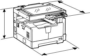
Dimensions of the equipment .................. |
W 600 x D 658.6 x H 462.5 (mm): See the figure below |
D
H
W
Fig. 1-1
e-STUDIO182/212/242 |
© 2009 TOSHIBA TEC CORPORATION All rights reserved |
SPECIFICATIONS / ACCESSORIES / OPTIONS / SUPPLIES |
|
1 - 4

1.2Accessories
Unpacking/setup instruction |
1 set |
1 |
Operator’s manual |
1 pc. |
|
Operator’s manual pocket |
1 pc. (for NAD) |
|
Power cable |
1 pc. |
|
CD-ROM |
2 pcs. |
|
Rubber cap |
6 pcs. (for MJD, ASD, ASU and SAD) |
|
|
2 pcs. (for NAD, CND, AUD, TWD, KRD and ARD) |
|
Transfer charger wire cleaner |
1 pc. |
|
(installed inside of the transfer cover) |
|
|
Drum (installed inside of the equipment) |
1 pc. |
|
Developer material |
1 pc. |
|
Nozzle |
1 pc. (for NAD) |
|
Toner cartridge |
1 pc. |
|
Warranty sheet |
1 pc. (for NAD and CND) |
|
Setup report |
1 set (for NAD, MJD and CND) |
|
Customer satisfaction card |
1 pc. (for MJD) |
|
Packing list |
1 pc. (for CND) |
|
Customer survey sheet |
1 pc. (for CND) |
|
Certificate of conformance |
1 pc. (for CND) |
|
*Machine version
NAD: |
North America |
ASD: |
Hong Kong / Latin America |
AUD: |
Australia |
MJD: |
Europe |
ASU: |
Asia / Saudi Arabia |
SAD: |
Saudi Arabia |
ARD: |
Latin America |
CND: |
China |
TWD: |
Taiwan |
KRD: |
Korea |
JPD: |
Japan |
© 2009 TOSHIBA TEC CORPORATION All rights reserved |
e-STUDIO182/212/242 |
|
SPECIFICATIONS / ACCESSORIES / OPTIONS / SUPPLIES |
1 - 5
1.3 |
Options |
|
|
|
|
Platen Cover |
KA-1650PC/PCC |
|
|
|
|
Automatic Document Feeder (ADF) |
MR-2020/C |
|
|
|
|
Reversing Automatic Document Feeder (RADF) |
MR-3023/C |
|
|
|
|
Paper Feed Unit (PFU) |
MY-1027/C |
|
|
|
|
Paper Feed Pedestal (PFP) |
KD-1022/C |
|
|
|
|
Paper Feed Controller (PFC) |
GH-1060/C |
|
|
|
|
Drawer Module |
MY-1028/C |
|
|
|
|
Automatic Duplexing Unit (ADU) |
MD-0103/C |
|
|
|
|
Fax Kit |
|
GD-1221NA/EU/AU/TW/CN/KR |
|
|
|
External Keyboard |
GJ-1060/C/EU/KR/TW |
|
|
|
|
Network Printer Kit |
GA-1191/C/KR/TW |
|
|
|
|
Scanner Upgrade Kit |
GA-1201/C/KR/TW |
|
|
|
|
Operator’s manual pocket |
KK-1660/C |
|
|
|
|
Damp Heater |
MF-1640U/E |
|
|
|
|
Harness Kit |
GQ-1130 |
|
|
|
|
Desk |
|
MH-1640 |
|
|
|
Notes:
•When the paper feed pedestal (KD-1022) or automatic duplexing unit (MD-0103) is installed, the paper feed controller (GH-1060) is also required to be installed.
•The external keyboard (GJ-1060) is necessary for the installation of the fax kit (GD-1221) and the scanner upgrade kit (GA-1201).
e-STUDIO182/212/242 |
© 2009 TOSHIBA TEC CORPORATION All rights reserved |
SPECIFICATIONS / ACCESSORIES / OPTIONS / SUPPLIES |
|
1 - 6

1.4Supplies
Drum |
OD-1600 (except for China) |
1 |
|
OD-2320 (for China) |
|
Toner cartridge |
PS-ZT1810 (1) (for North America) |
|
|
PS-ZT1810A (1) (for Central and South America) |
|
|
PS-ZT1810D (1) (for Asia) |
|
|
PS-ZT1810D5k (1) (for Asia) |
|
|
PS-ZT1810C (1) (for China) |
|
|
PS-ZT1810C10k (1) (for China) |
|
|
PS-ZT1810C5k (1) (for China) |
|
|
PS-ZT1810T (1) (for Taiwan) |
|
|
PS-ZT1810T5k (1) (for Taiwan) |
|
|
PS-ZT1810E (1) (for Europe) |
|
|
PS-ZT1810E5K (1) (for Europe) |
|
Developer material |
D-2320 (except for China) |
|
|
D-2320C (for China) |
|
© 2009 TOSHIBA TEC CORPORATION All rights reserved |
e-STUDIO182/212/242 |
|
SPECIFICATIONS / ACCESSORIES / OPTIONS / SUPPLIES |
1 - 7
ACCESSORIES / SPECIFICATIONS |
STUDIO182/212/242-e |
SUPPLIES / OPTIONS / |
|
8 - 1
reserved rights All CORPORATION TEC TOSHIBA 2009 ©
2-1 .Fig
|
|
|
|
|
Automatic |
Reversing Automatic |
||||
|
|
|
|
|
Document Feeder |
|
|
|
Document Feeder |
|
|
|
|
|
|
|
|
|
|
||
|
Platen Cover |
|
|
|
(ADF) |
|
|
(RADF) |
||
|
KA-1650PC |
|
|
|
MR-2020 |
|
|
MR-3023 |
||
|
|
|
|
|
|
|
|
|
|
|
|
|
|
|
|
|
|
|
|
|
|
|
|
|
|
|
|
|
|
|
|
|
|
|
|
|
|
|
|
|
|
|
|
|
|
|
|
|
|
|
|
|
|
|
|
|
|
|
|
|
|
External Keyboard |
|
|
|
|
|
|
|
|
|
|
|
|
|
|
|
|
|
|
|
|
|
|
|
|
|||
|
|
|
|
|
|
|
|
|
|
|
|
|
|
|
|
|
|
|
|
|
|
|
|
|
|
|
|
|
|
|
|||
|
|
|
|
|
|
GJ-1060 |
|
|
|
|
|
|
|
|
|
|
|
|
|
|
|
|
|
|
|
|
|
|
|
|
|||
|
|
|
|
|
|
|
|
|
|
|
|
|
|
|
|
|
|
|
|
|
|
|
|
|
|
|
|
||||||
|
|
|
|
|
|
|
|
|
|
|
|
|
|
|
|
|
|
|
|
|
|
|
|
|
|
|
|
|
|
|
|
||
|
Harness Kit |
|
|
|
Damp Heater |
|
|
|
|
|
|
|
|
|
|
|
|
|
|
|
|
|
|
|
Automatic |
|
|
||||||
|
GQ-1130 |
|
|
MF-1640 |
|
|
|
|
|
|
|
|
|
|
|
|
|
|
|
|
|
|
|
|
|
||||||||
|
|
|
|
|
|
|
|
|
|
|
|
|
|
|
|
|
|||||||||||||||||
|
|
|
|
|
|
|
|
|
|
|
|
|
|
|
|
|
|
|
|
|
Duplexing Unit |
|
|
||||||||||
|
|
|
|
|
|
|
|
|
|
|
|
|
|
|
|
|
|
|
|||||||||||||||
|
|
|
|
|
|
|
|
|
|
|
|
|
|
|
|
|
|
|
|
|
|
|
|
|
|
|
|
|
(ADU) |
|
|
||
|
|
|
|
|
|
|
|
|
|
|
|
|
|
|
|
|
|
|
|
|
|
|
|
||||||||||
|
|
|
|
|
|
|
|
|
|
|
|
|
|
|
|
|
|
|
|
|
|
|
|
|
|
|
|
|
MD-0103 |
|
|
||
|
|
|
|
|
|
|
|
|
|
|
|
|
|
|
|
|
|
|
|
|
|
|
|
|
|
|
|
|
|
||||
|
|
|
|
|
|
|
|
|
|
|
|
|
|
|
|
|
|
|
|
|
|
|
|
|
|
|
|
|
|
|
|
||
|
|
|
|
|
|
|
|
|
|
|
|
|
|
|
|
|
|
|
|
|
|
|
|
|
|
|
|
|
|
|
|
|
|
|
|
|
|
|
|
|
|
|
|
|
|
|
|
|
|
|
|
|
|
|
|
|
|
|
|
|
|
|
Paper Feed |
|
|
||
|
|
|
|
|
|
|
|
|
|
|
|
|
|
|
|
|
|
|
|
|
|
|
|
|
|
|
|
|
|
|
|||
|
|
|
|
|
|
|
|
|
|
|
|
|
|
|
|
|
|
|
|
|
|
|
|
||||||||||
|
Fax Kit |
|
|
|
Network |
|
|
|
|
|
|
|
|
|
|
|
|
|
|
|
|
|
|
|
Controller |
|
|
||||||
|
GD-1221 |
|
|
Printer Kit |
|
|
|
|
|
|
|
|
|
|
|
|
|
|
|
|
|
|
(PFC) |
|
|
||||||||
|
|
|
|
|
|
|
|
|
|
|
|
|
|
|
|
|
|
|
|
||||||||||||||
|
|
|
GA-1191 |
|
|
|
|
|
|
|
|
|
|
|
|
|
|
|
|
|
|
|
GH-1060 |
|
|
||||||||
|
|
|
|
|
|
|
|
|
|
|
|
|
|
|
|
|
|
|
|
|
|
|
|
|
|
||||||||
|
|
|
|
|
|
|
|
|
|
|
|
|
|
|
|
|
|
|
|
|
|
|
|
|
|
|
|
|
|
|
|
|
|
|
|
|
|
|
|
|
|
|
|
|
|
|
|
|
|
|
|
|
|
|
|
|
|
|
|
|
|
|
|
|
|
|
|
|
|
|
|
|
|
Scanner |
|
|
|
|
|
|
|
|
|
|
|
|
|
|
Paper Feed Unit |
|
|
|
|
||||||||
|
|
|
|
|
|
Upgrade Kit |
|
|
|
|
|
|
|
|
|
|
|
|
|
(PFU) |
|
|
|
|
|||||||||
|
|
|
|
|
|
|
|
|
|
|
|
|
|
|
|||||||||||||||||||
|
|
|
|
|
|
GA-1201 |
|
|
|
|
|
|
|
|
|
|
|
|
|
MY-1027 |
|
|
|
||||||||||
|
|
|
|
|
|
|
|
|
|
|
|
|
|
|
|||||||||||||||||||
|
|
|
|
|
|
|
|
|
|
|
|
|
|
|
|
|
|
|
|
|
|
|
|
|
|
|
|
|
|
|
|
|
|
|
|
|
|
|
|
|
|
|
|
|
|
|
|
|
|
|
|
|
|
|
|
|
|
|
|
|
|
|
|
|
|
|
|
|
|
|
|
|
|
|
|
|
|
|
|
|
|
|
|
|
|
|
|
|
|
|
|
|
|
|
|
|
|
|
|
|
|
|
|
|
|
|
|
|
|
|
|
|
|
|
|
|
|
|
|
|
|
|
|
|
|
|
|
|
|
|
|
|
|
|
|
|
|
|
|
|
|
|
|
|
|
|
|
|
|
|
|
|
|
|
|
|
|
|
|
|
|
|
|
|
|
|
|
|
|
|
|
|
|
|
|
|
|
|
|
|
|
|
|
|
|
|
|
|
|
|
|
|
|
|
|
|
|
|
|
|
|
|
|
|
|
|
|
|
Paper Feed |
|
|
|
|
|
|
Drawer Module |
|
|
|
Pedestal |
|
|
|
Desk |
|
|
MY-1028 |
|
|
|
(PFP) |
|
|
MH-1640 |
||
|
|
|
|
|
KD-1022 |
|
|
|
|
|
|
|
|
|
|
|
|
|
|
||
|
|
|
|
|
|
|
|
|
|
|
List System 5.1
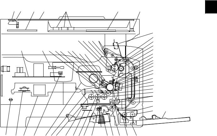
2.OUTLINE OF THE MACHINE
2.1Sectional View
1. |
Front side |
|
|
|
|
|
|
|
|
|
2 |
|
|
A2 |
A3 |
A4 |
A1 |
|
|
A7 |
|
A5 |
A6 |
|
|
|
|
|
|
|
|
|||||||
|
|
|
|
|
|
|
|
|
|
|
K5 |
|
|
|
|
|
|
|
|
|
J6 J7 J5 J4 |
J8 |
|
J3 |
|
|
|
|
|
|
|
|
|
|
J9 |
|
||
|
|
|
|
|
|
|
|
|
|
|
|
|
|
|
K4 |
|
K2 |
I5 |
I9 F3 |
F2F1 |
|
|
|
J1 |
|
|
|
|
H2 H3 |
|
|
J2 |
|
|||||
|
|
|
|
|
|
|
|
|
|
L3 |
|
|
|
|
|
|
|
|
|
|
|
|
|
L1 |
|
|
|
|
|
|
|
|
|
|
|
|
I7 |
|
|
|
|
|
|
|
|
|
|
|
|
H4 |
|
|
|
|
|
|
|
|
|
|
|
|
H5 |
|
|
|
|
|
|
|
|
|
|
|
|
H1 |
|
|
|
|
|
|
|
|
|
|
|
|
G2 |
|
|
|
|
|
|
|
|
|
|
|
|
G1 |
|
|
|
|
|
|
|
|
|
|
|
|
G3 |
|
|
|
|
|
|
|
|
|
|
|
|
L3 |
|
|
|
|
|
|
|
|
|
|
|
|
I1 |
|
|
|
|
|
|
|
|
|
|
|
|
I2 |
|
|
|
|
|
|
|
|
|
|
|
|
C5 |
|
|
|
|
|
|
|
|
|
|
|
|
L2 |
|
|
|
|
|
|
|
|
|
|
|
|
E2 |
E5 |
|
|
|
|
|
|
|
|
|
|
|
E1 |
|
|
|
|
|
|
|
|
|
|
|
|
|
|
K3 |
B2 |
B1 |
K1 |
F4 |
I8 |
I4 |
I11 I10 I3 |
I6 |
C3 |
C1 C2 C4 |
|
|
|
E4 |
||
E3 |
|
|||||||||||||||
|
|
|
|
|
|
|
|
|
Fig. 2-1 |
|
|
|
|
|||
|
|
|
|
|
|
|
|
|
|
|
|
|
|
|
||
A1 |
Original glass |
|
|
|
|
|
|
|
|
|
|
|
|
|
||
|
|
|
|
|
|
|
|
|
|
|
|
|
|
|||
A2 |
ADF original glass |
|
|
|
|
|
|
|
|
|
|
|
|
|||
|
|
|
|
|
|
|
|
|
|
|
||||||
A3 |
Contact image sensor unit (CIS) |
|
|
|
|
|
|
|
|
|
||||||
|
|
|
|
|
|
|
|
|
|
|
||||||
A4 |
Scanner damp heater (Left side) |
|
|
|
DH1 |
|
|
|
|
|
||||||
|
|
|
|
|
|
|
|
|
|
|
||||||
A5 |
Scanner damp heater (Right side) |
|
|
|
DH2 |
|
|
|
|
|
||||||
|
|
|
|
|
|
|
|
|
|
|
||||||
A6 |
Scanner damp heater thermostat |
|
|
|
THMO2 |
|
|
|
|
|
||||||
|
|
|
|
|
|
|
|
|
|
|
||||||
A7 |
Automatic original detection sensor |
|
|
|
S9-S13 |
|
|
|
|
|
||||||
|
|
|
|
|
|
|
|
|
|
|
|
|
|
|
||
B1 |
Laser optical unit |
|
|
|
|
|
|
|
|
|
|
|
|
|
||
|
|
|
|
|
|
|
|
|
|
|
|
|
|
|
||
B2 |
Polygonal motor |
|
|
|
|
|
|
|
M4 |
|
|
|
|
|
||
|
|
|
|
|
|
|
|
|
|
|
|
|
|
|
||
C1 |
Pickup roller |
|
|
|
|
|
|
|
|
|
|
|
|
|
||
|
|
|
|
|
|
|
|
|
|
|
|
|
|
|
||
C2 |
Separation claw |
|
|
|
|
|
|
|
|
|
|
|
|
|
||
|
|
|
|
|
|
|
|
|
|
|
|
|
|
|||
C3 |
Paper empty sensor |
|
|
|
|
|
|
S7 |
|
|
|
|
|
|||
|
|
|
|
|
|
|
|
|
|
|
|
|
|
|||
C4 |
Registration sensor |
|
|
|
|
|
|
S4 |
|
|
|
|
|
|||
|
|
|
|
|
|
|
|
|
|
|
|
|
|
|
||
C5 |
Registration roller |
|
|
|
|
|
|
|
|
|
|
|
|
|
||
|
|
|
|
|
|
|
|
|
|
|
|
|
|
|||
E1 |
Bypass pickup roller |
|
|
|
|
|
|
|
|
|
|
|
|
|||
|
|
|
|
|
|
|
|
|
|
|
|
|
|
|
||
E2 |
Bypass feed roller |
|
|
|
|
|
|
|
|
|
|
|
|
|
||
|
|
|
|
|
|
|
|
|
|
|
|
|
||||
E3 |
Bypass separation pad |
|
|
|
|
|
|
|
|
|
|
|
||||
|
|
|
|
|
|
|
|
|
|
|
|
|
|
|||
E4 |
Bypass paper sensor |
|
|
|
|
|
|
S8 |
|
|
|
|
|
|||
|
|
|
|
|
|
|
|
|
|
|
||||||
© 2009 TOSHIBA TEC CORPORATION All rights reserved |
|
|
|
|
|
|
|
|
e-STUDIO182/212/242 |
|||||||
|
|
|
|
|
|
|
|
|
|
|
|
|
|
|
|
OUTLINE OF THE MACHINE |
2 - 1
E5 |
Bypass tray |
|
|
|
|
F1 |
Needle electrode |
|
|
|
|
F2 |
Main charger |
|
|
|
|
F3 |
Main charger grid |
|
|
|
|
F4 |
Toner cartridge |
|
|
|
|
G1 |
Transfer charger wire |
|
|
|
|
G2 |
Separation charger wire |
|
|
|
|
G3 |
Transfer guide roller |
|
|
|
|
H1 |
Drum |
|
|
|
|
H2 |
Discharge LED |
|
|
|
|
H3 |
Drum cleaning blade |
|
|
|
|
H4 |
Recovery blade |
|
|
|
|
H5 |
Drum separation finger |
|
|
|
|
I1 |
Developer sleeve (Magnetic roller) |
|
|
|
|
I2 |
Mixer-1 |
|
|
|
|
I3 |
Mixer-2 |
|
|
|
|
I4 |
Mixer-3 |
|
|
|
|
I5 |
Doctor blade |
|
|
|
|
I6 |
Auto-toner sensor |
S6 |
|
|
|
I7 |
Toner recovery auger |
|
|
|
|
I8 |
Toner recycle auger |
|
|
|
|
I9 |
Drum thermistor |
THMS4 |
|
|
|
I10 |
Drum damp heater |
DH3 |
|
|
|
I11 |
Drum damp heater thermostat |
THMO3 |
|
|
|
J1 |
Fuser roller |
|
|
|
|
J2 |
Pressure roller |
|
|
|
|
J3 |
Fuser roller separation finger |
|
|
|
|
J4 |
Center heater lamp |
LAMP1 |
|
|
|
J5 |
Side heater lamp |
LAMP2 |
|
|
|
J6 |
Center/Side/Edge thermistor |
THMS1/2/3 |
|
|
|
J7 |
Fuser thermostat |
THMO1 |
|
|
|
J8 |
Exit roller |
|
|
|
|
J9 |
Exit sensor |
S5 |
|
|
|
K1 |
Front cover opening/closing switch |
SW4 |
|
|
|
K2 |
Front cover opening/closing interlock switch |
SW3 |
|
|
|
K3 |
Temperature/humidity sensor |
S3 |
|
|
|
K4 |
Switching regulator |
|
|
|
|
K5 |
ADU cover opening/closing interlock switch |
SW2 |
|
|
|
L1 |
ADU upper transport roller |
|
|
|
|
L2 |
ADU lower transport roller |
|
|
|
|
L3 |
ADU paper guide |
|
|
|
|
e-STUDIO182/212/242 |
© 2009 TOSHIBA TEC CORPORATION All rights reserved |
OUTLINE OF THE MACHINE |
|
2 - 2
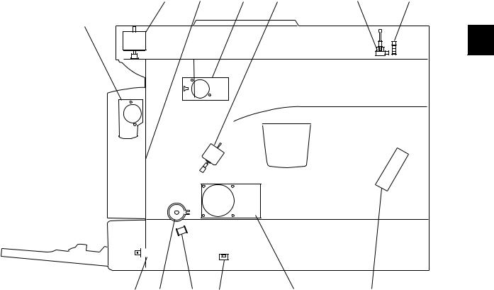
2. Rear side
M1 |
M5 |
M7 |
M2 |
S2 |
S1 |
M8
2 |
|
|
|
|
|
|
|
|
|
|
|
|
|
|
|
|
|
|
|
|
|
|
|
|
|
|
|
|
|
|
|
|
|
|
|
|
|
|
|
|
|
|
|
|
|
|
|
|
|
|
|
|
|
|
SOL2 CLT1 SOL1 SW5 |
M3 |
M6 |
||||||
Fig. 2-2
M1 |
Scan motor |
|
|
M2 |
Toner motor |
|
|
M3 |
Main motor |
|
|
M5 |
Exhaust fan |
|
|
M6 |
Switching regulator cooling fan |
|
|
M7 |
Exit motor (Option) |
|
|
M8 |
ADU motor (Option) |
|
|
S1 |
CIS home position sensor |
|
|
S2 |
Platen sensor |
|
|
SW5 |
Drawer detection switch |
|
|
CLT1 |
Registration clutch |
|
|
SOL1 |
Pickup solenoid |
|
|
SOL2 |
Bypass pickup solenoid |
|
|
© 2009 TOSHIBA TEC CORPORATION All rights reserved |
e-STUDIO182/212/242 |
|
OUTLINE OF THE MACHINE |
2 - 3
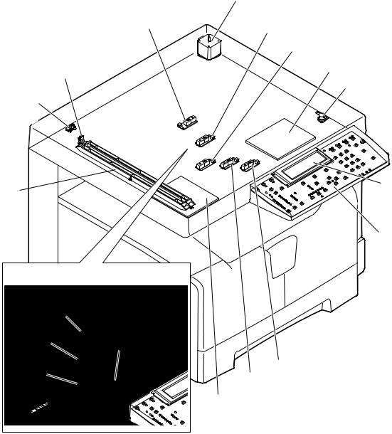
2.2Electric Parts Layout
[A] Scanner, control panel
S13
S1
S2
CIS 
LT series models
S13
S12 S10
S11
M1
S12
S11
DH2
THMO2
LCD
HPNL
S10
S9
DH1
Fig. 2-3
e-STUDIO182/212/242 |
© 2009 TOSHIBA TEC CORPORATION All rights reserved |
OUTLINE OF THE MACHINE |
|
2 - 4
Loading...