

Page 1
E6581737
TOSVERT VF-MB1/S15
Option Function Manual
DEV003Z-1
1. Read this manual before installing or operating. Keep this instruction manual on hand
of the end user, and make use of this manual in maintenance and inspection.
2. All information contained in this manual will be changed without notice. Please
contact your Toshiba distributor to confirm the latest information.
NOTICE
© Toshiba Schneider Inverter Corporation
All rights reserved.
2006
Page 2

E6581737
Contents
Introduction............................................................................................................................................ 2
1.
2. Connection Information ......................................................................................................................... 6
2.1. Connection Sizes............................................................................................................................. 6
2.2. Exterior overview ............................................................................................................................. 6
2.3. DeviceNet LED indicator ................................................................................................................. 7
2.4. VF-MB1/S15 Communications-related parameters......................................................................... 8
3. Object Specifications............................................................................................................................. 9
3.1. Identity Object................................................................................................................................ 10
3.2. Message Router Object................................................................................................................. 12
3.3. DeviceNet Object........................................................................................................................... 13
3.4. Assembly Object............................................................................................................................ 14
3.5. Connection Object ......................................................................................................................... 32
3.6. Motor Data Object.......................................................................................................................... 36
3.7. Control Supervisor Object ............................................................................................................. 37
3.8. AC/DC Drive Object....................................................................................................................... 40
3.9. Acknowledge Handler Object ........................................................................................................ 42
3.10. Parameter Object (Vender Specific Profiles)................................................................................. 43
4. DeviceNet Local/Remote Operation.................................................................................................... 44
5. EDS file................................................................................................................................................ 44
- 1 -
- 1 -
Page 3

E6581737
1. Introduction
Thank you for purchasing the DeviceNet option “DEV003Z” for the VF-MB1/S15. Before using
the DeviceNet option, please familiarize yourself with the product and be sure to thoroughly
read the instructions and precautions contained in this manual.
In addition, please make sure that this manual and “Installation Manual” is delivered to the end
user, and keep this function manual in a safe place for future reference or drive/interface
inspection.
This option needs the option adaptor to connect VF-S15 which type form is SBP009Z. Please
match here and buy it when SBP009Z is not at hand yet.
This manual describes the supported functions for the “DEV003Z”.
In conjunction with this manual, the following manuals are supplied by Toshiba, and are
essential both for ensuring a safe, reliable system installation as well as for realizing the full
potential of the “DEV003Z”:
- TOSVERT VF-MB1 Instruction Manual................................................E6581697
- TOSVERT VF-S15 Instruction Manual.................................................E6581611
- VF-MB1/S15 communication option Precautions Manual ..................E6581739
- 2 -
Page 4
E6581737
Safety precautions
On the inverter and in its instruction manual, important information is contained for preventing
injuries to users and damages to assets and for proper use of the device. Read the instruction
manual attached to VF-MB1/S15 along with this instruction manual for completely
understanding the safety precautions and adhere to the contents of these manuals.
Explanation of markings
Marking Meaning of marking
Indicates that errors in operation may lead to death or serious injury.
Warning
Indicates that errors in operation may lead to injury (*1) to people or that these errors
Caution
(*1) Such things as injury, burns or shock that will not require hospitalization or long periods of outpatient
treatment.
(*2) Physical property damage refers to wide-ranging damage to assets and materials.
Meanings of symbols
Marking Meaning of marking
may cause damage to physical property. (*2)
Indicates prohibition (Don't do it).
What is prohibited will be described in or near the symbol in either text or picture
form.
Indicates something mandatory (must be done).
What is mandatory will be described in or near the symbol in either text or picture form.
Indicates warning.
What is warned will be described in or near the symbol in either text or picture form.
Indicates caution.
What the caution should be applied to will be described in or near the symbol in
either text or picture form.
- 3 -
Page 5
E6581737
■ General Operation
Disassembly
prohibited
Prohibited
Mandatory
■ Transportation & installation
Prohibited
▼ Never disassemble, modify or repair.
Doing so could result in electric shock, fire and injury. For repairs, call your sales
agency.
▼ Do not attach this option to any inverter other than the VF-MB1/S15.
Doing so could result in electric shock or fire.
▼ When the inverter is energized, never detach the this option from the VF-MB1/S15.
Doing so could result in electric shock.
▼ Don't place or insert any kind of object into the DEV003Z (electrical wire cuttings, rods,
wires).
Doing so could result in electric shock or fire.
▼ Do not allow water or any other fluid to come in contact with the DEV003Z.
Doing so could result in electric shock or fire.
▼ Turn off the VF-MB1/S15 when installing and wiring this option.
▼ If the inverter begins to emit smoke or an unusual odor, or unusual sounds, immediately
turn power off.
If the equipment is continued in operation in such a state, the result may be fire. Call
your local sales agency for repairs.
▼ Do not operate the inverter if it is damaged or any component is missing.
Doing so could result in electric shock or fire. Call your local sales agency for repairs.
▼ Do not place any inflammable substances near the VF-MB1/S15 Inverter.
If an accident occurs in which flame is emitted, this could lead to fire.
▼ Do not install in any location where the inverter could come into contact with water or
other fluids.
Doing so could result in electric shock or fire.
Warning
Warning
Mandatory
■ Wiring
Mandatory
▼ Operate under the environmental conditions prescribed in the instruction manual.
Operations under any other conditions may result in malfunction.
Warning
▼ Shut off power when installing and wiring this option.
Wait at least 15 minutes and check to make sure that the charge lamp (VF-MB1/S15) is
no longer lit.
▼ Electrical construction work must be done by a qualified expert.
Installation or connection of input power by someone who does not have that expert
knowledge may result in fire or electric shock.
- 4 -
Page 6
■ Operations
Prohibited
Mandatory
■ Disposal
Mandatory
E6581737
Warning
▼ Do not touch switches when the hands are wet and do not try to clean the inverter with a
damp cloth.
Doing so could result in electric shock.
▼ Do not pull on any cable itself.
Doing so could result in damage or malfunction.
▼ Check DeviceNet state (using below attribute) when the option unit is deactivated by an
unusual event such as an operating error, power outage, failure, etc.
- Identity Object Instance Attributes 8 (State)
(The communication error occurs when Fault (4, 5) or this value cannot be read.)
Deactivated option unit may cause an accident, if the DeviceNet state is not checked.
▼ Make sure that the operation signals are STOP before clearing the inverter’s fault.
The motor may suddenly start and that may result in injuries.
Caution
▼ For safety's sake, do not dispose of the disused inverter yourself but ask an industrial
waste disposal agent (*).
If the collection, transport and disposal of industrial waste is done by someone who is
not licensed for that job, it is a punishable violation of the law. (Laws in regard to
cleaning and processing of waste materials)
(*) Persons who specialize in the processing of waste and known as “industrial waste
product collectors and transporters” or “industrial waste disposal persons.”
Notes on use
▼ Do not install the inverter where the temperature or the humidity will change rapidly.
▼ Keep a distance of 20cm or more between the inverter's power cable and the data
transmission cable.
Or the inverter might malfunction because of noise.
▼ Insert a magnetic contactor or similar device between the inverter and the power supply
to ensure that power is turned off if an emergency stop command is entered through the
network.
▼ When the control power is shut off by the instantaneous power failure, communication
will be unavailable for a while.
▼ The Life of EEPROM is approximately 100,000 times. Avoid writing a command more
than 100,000 times to the same parameter of the Inverter and the communication
board.
Notes
- 5 -
Page 7
E6581737
2. Connection Information
2.1. Connection Sizes
Connection Instance Produced Consumed
I/O Messaging
Explicit Messaging
- For the Polled I/O connection, if the actual consumed data size is bigger than the connection instance’s
consumed_connection_size attribute, the consumed data will be ignored, but the connection will otherwise
produce normally. If the actual consumed data size is larger than the connection instance’s
consumed_connection_size attribute, the consumed data will be ignored and the connection will not produce.
- For the Explicit Messaging connection, this is the maximum message length: shorter messages are also
acceptable.
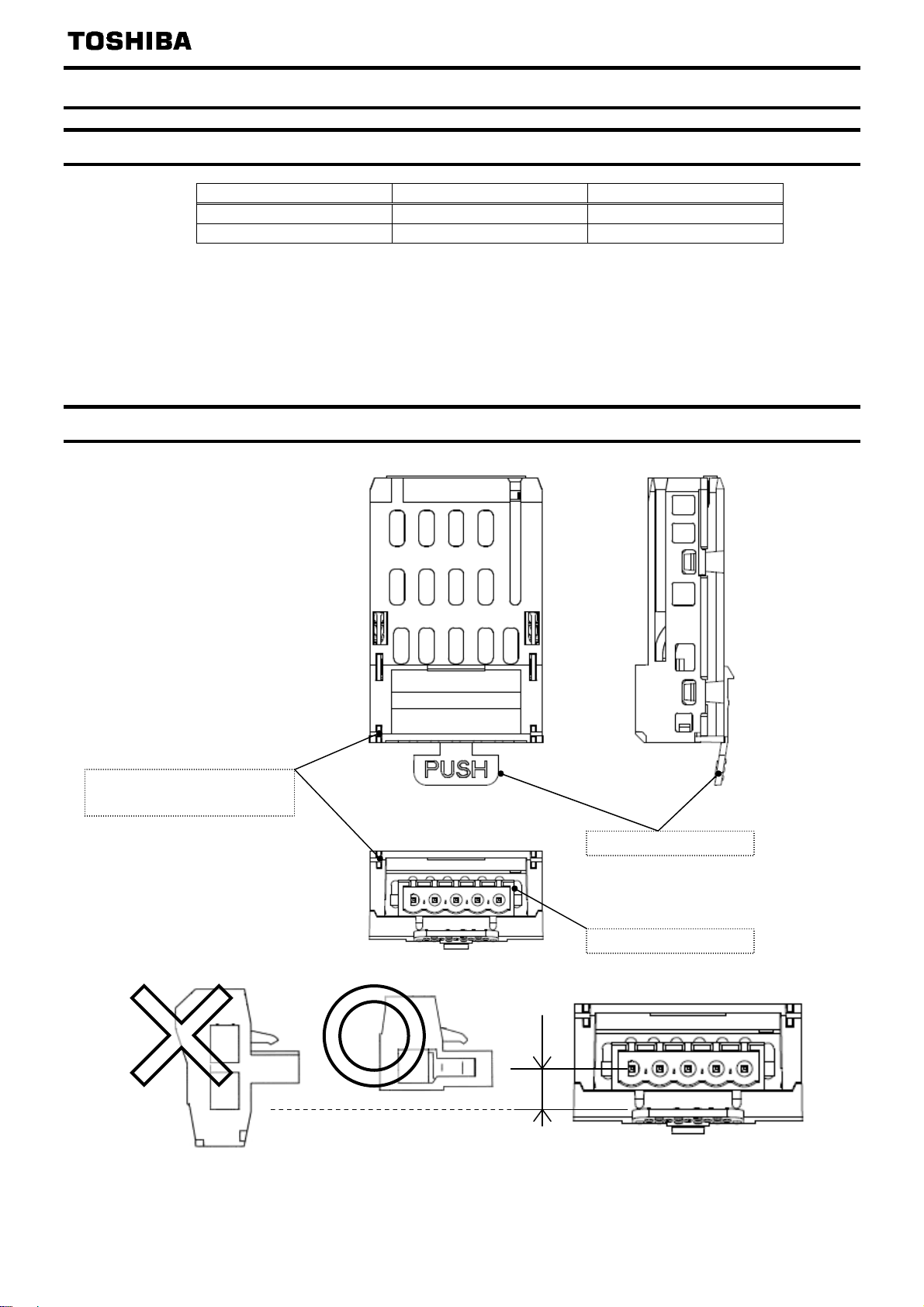
2.2. Exterior overview
4, 8, 12 or 18 bytes 4, 8, 12 or 18 bytes
39 bytes 39 bytes
DeviceNet LED indicator
(Refer to Section 2.3)
Release Tab
DeviceNet Connector
Multi-Drop type connector etc. can not be used for DEV003Z.
6mm
- 6 -
Page 8
E6581737
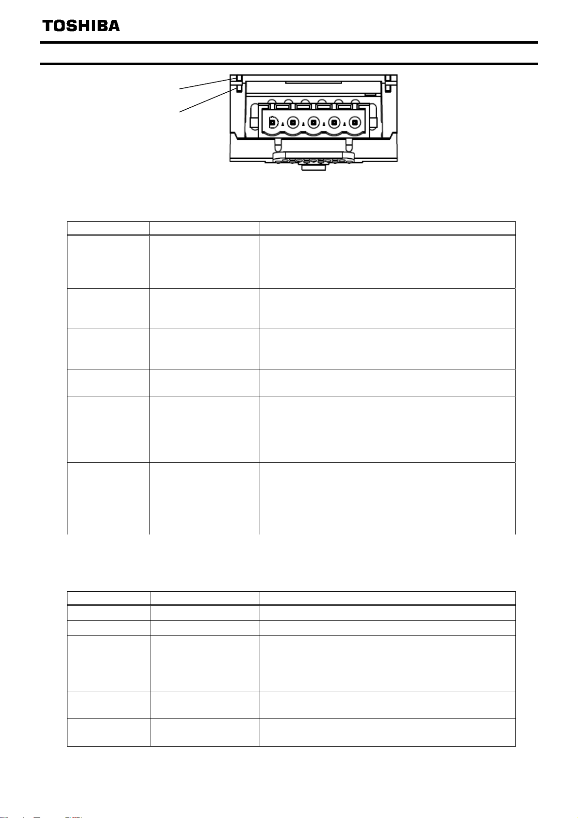
2.3. DeviceNet LED indicator
NS (Network status)
MS (Module status)
NS (Network status)
This bi–color (green/red) LED indicates the status of the communication link from the DEV003Z to DeviceNet.
(According to ODVA DeviceNet Specifications.)
LED is: For this state: To indicate:
Device is not on–line.
Off
Green On-line and connect
Flashing Green On-line, not connect
Flashing Red Connection Time-out
Red Critical Link Failure
Flashing
Red-Green
MS (Module status)
This bi–color (green/red) LED indicates the status of the communication link from DEV003Z to the
VF-MB1/S15. It indicates whether or not the device has power and is operating properly.
(According to ODVA DeviceNet Specifications.)
LED is: For this state: To indicate:
Off Power OFF
Green Device Operational
Flashing Green Device in Standby
Flashing Red Minor Fault
Red Unrecoverable Fault
Flashing
Red-Green
Not Powered/Not
On–line
Communication
Faulted and Received
an Identify Comm Fault
Request - Long
Protocol
Device Self Testing The Device is in Self Test.
- The device has not completed the Dup_MAC_ID test yet.
- The device may not be powered, look at Module Status
LED.
The device is on–line and has connections in the
established state.
- The device is allocated to a Master.
Device is connected to the network but has no connections
in the established state.
- The device is not allocated to a master.
Recoverable Fault. One or more I/O Connections are in
the Timed–Out state.
Non Recoverable fault. The device has detected an error
that has rendered it incapable of communicating on the
network (Duplicate MAC ID, or Bus–off). Check
parameters
this fault.
A specific Communication Faulted device. The device has
detected a Network Access error and is in the
Communication Faulted state.
The device has subsequently received and accepted an
Identify Communication Faulted Request - Long Protocol
There is no power applied to the device.
The device is operating in a normal condition.
The device needs commissioning due to configuration
missing, incomplete or incorrect.
The Device may be in the Standby state.
Recoverable Fault.
The device has an unrecoverable fault; may need
replacing.
c200 then Cycle power to VF-MB1 to reset
- 7 -
Page 9
E6581737
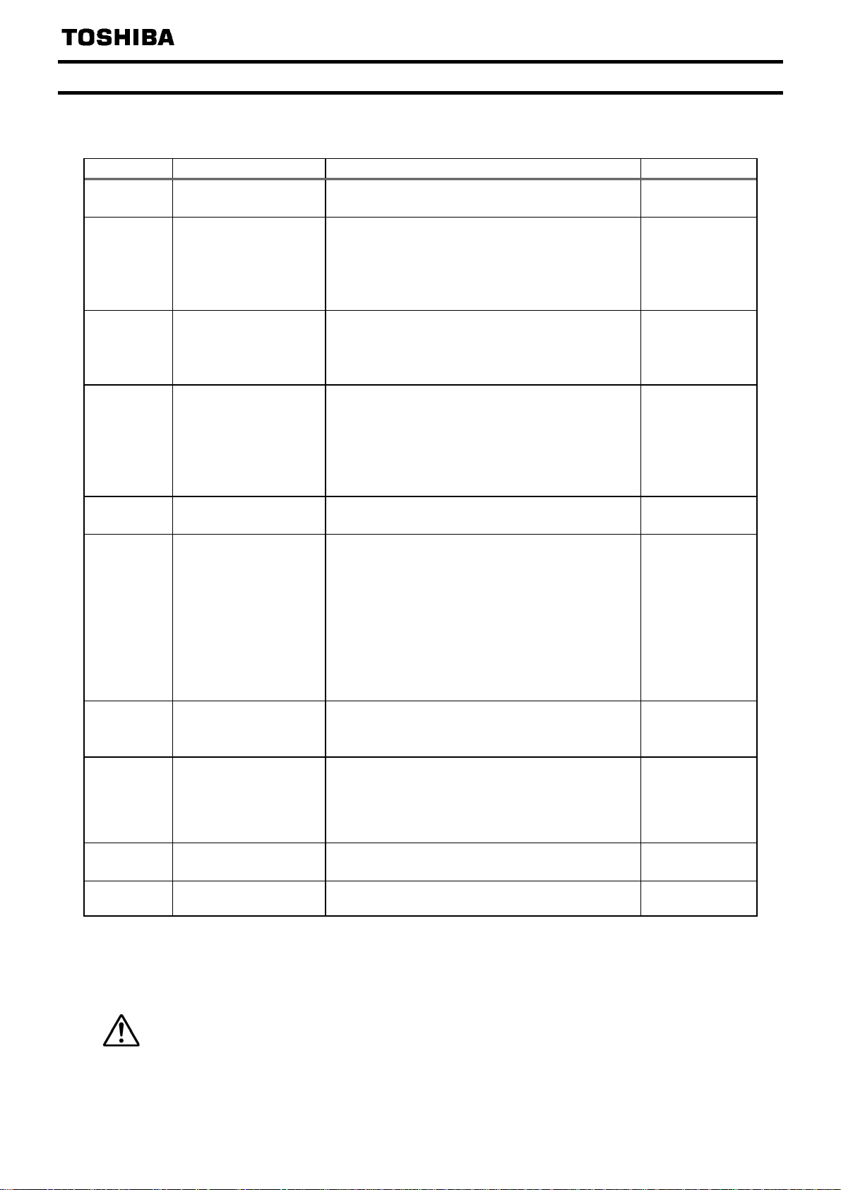
2.4. VF-MB1/S15 Communications-related parameters
In a network, VF-MB1/S15 (DEV003Z) serves as a DeviceNet slave device. DEV003Z
configuration is set by the following parameters.
Parameter Function Adjustment range Default setting
c200
DEV003Z
MAC ID
c201
DEV003Z
Communication
baud rate
c202
DeviceNet
Baud rate monitor
c203
DEV003Z
Assembly Object
c100
Communication error
detection delay time
c101
Inverter operation at the
communications
loss action
(Network wire breaks)
c102
Preset speed
operation selection
c103 Communication
time-out condition
selection
f899 Network option
reset setting
fd67 DEV003Z versioon DEV003Z firmware version
* DeviceNet baud rate is 500kbps and with a few slaves in the network, auto baud rate function might not
work.
** Do not set at VF-MB1 V1.00.
*** When the parameter is changed, the power must be cycled (or set
changes to take effect.
1 to f899 by the DeviceNet communication might not be able to be set.
Please note that inverter keeps driving when the communication is lost if
Caution
parameter
c101 (Inverter operation at the communications loss action).
0 to 63 63
DEV003Z communication baud rate is set.
0
0: AUTO *
1: 125kbps
2: 250kbps
3: 500kbps
DeviceNet communication baud rate is shown.
1: 125kbps
2: 250kbps
3: 500kbps
0: Instance 20/70
0
1: Instance 21/71
2: Instance 100/150
3: Instance 101/151
4: Instance 102/152
5: Instance 105/155
0.0 to 100.0s 0.0
0: Stop and Communication release **
(follows
cmod and fmod setting)
4
1: None
2: Deceleration stop
3: Coast stop
4: Emergency stop (
err8) ***
5: Preset speed operation command
(Operating at the preset speed operation
frequency set with
0: None
c102)
0
1 to 15:Preset speed
(
sr1 - sr7, f287 - f295)
0: Disconnection detection
0
1: When communication mode enable (Both
cmod and fmod are set CANopen or COM
option)
2: 1+Driving operation
0: None
0
1: Resetting the DEV003Z and the inverter
-
(ex. 0x1101 means "V1.01")
f899 to 1) to the VF-MB1/S15 for the
1 (None) is set to the
- 8 -
Page 10
E6581737
3. Object Specifications
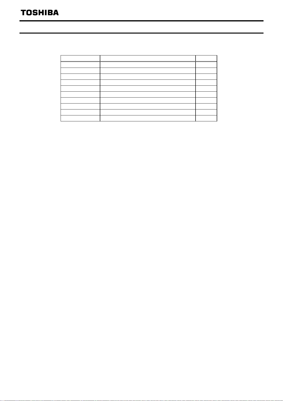
This section contains the object specifications for all DeviceNet objects currently supported by
the “DEV003Z”. Table 1 outlines those objects covered:
Class Code Object Class
0x01
0x02
0x03
0x04
0x05
0x28
0x29
0x2A
0x2B
0x65 (0x64)
For definitions of all data types referred to in these object specifications, refer to the ODVA
DeviceNet Specifications. In general, however, the following are some of the most prevalent
types:
SINT ................. Signed 8-bit integer value
USINT ..............Unsigned 8-bit integer value
BYTE................Bit string - 8-bits
INT ...................Signed 16-bit integer value
UINT.................Unsigned 16-bit integer value
WORD..............Bit string - 16-bits
UDINT ..............Unsigned 32-bit integer value
Identity Object
Message Router Object
DeviceNet Object
Assembly Object
Connection Object
Motor Data Object
Control Supervisor Object
AC/DC Drive Object
Acknowledge Handler Object
Parameter Object (Vender Specific Profiles)
Table 1: Supported Objects
Page
10
12
13
14
33
37
38
41
42
43
- 9 -
Page 11
E6581737
A
A
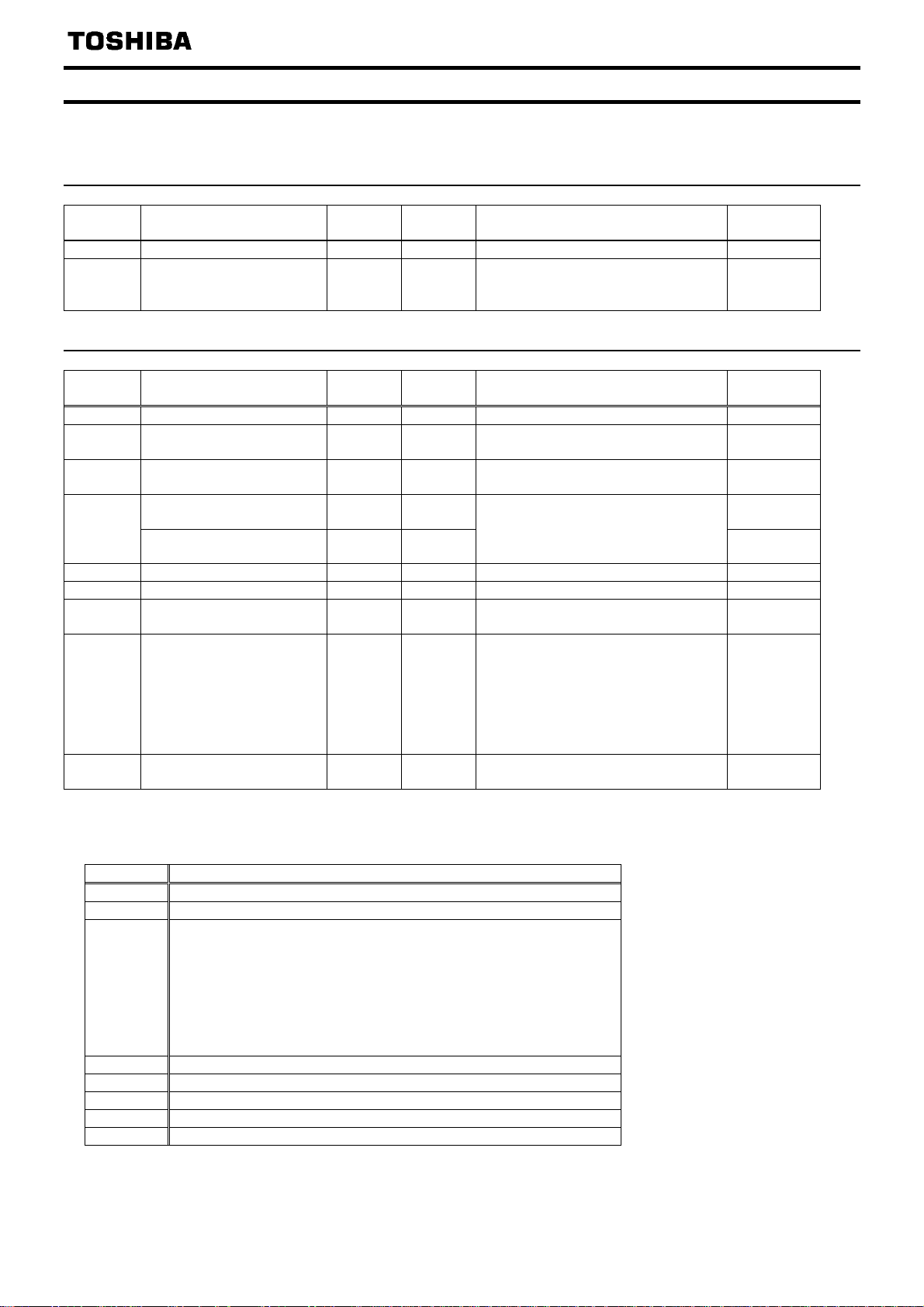
3.1. Identity Object
Class code 0x01. This object provides identification of and general information about the
device.
3.1.1.
Attribute
3.1.2.
Attribute
* DEV003Z software version.
ex.) If Major = 0x01 and Minor = 0x01, DEV003Z Version is "101".
** Attribute 5 Status:
Identity Object Class Attributes
ID
1 Revision UINT Get Revision of this object 1
2 Max instance UINT Get
Name
Data
Type
ccess
Rules
Description
Maximum instance number of an object
currently created in this class level of
the device
Identity Object Instance Attributes
ID
1 Vendor ID UINT Get Identification of vendor by number 377
2 Device type UINT Get Indication of general type of product
3 Product code UINT Get
Revision *
(Major)
4
Revision *
(Minor)
5 Status (bits supported) ** WORD Get Summary status of device 6 Serial number UDINT Get Serial number of device -
7 Product name
8 State USINT Get
10 Heartbeat Interval USINT Get/Set
Name
Data
Type
USINT
(ARRAY)
USINT
(ARRAY)
SHORT_
STRING
ccess
Rules
Identification of a particular product of
an individual vendor
Get (01)
Get
Get Human-readable identification “DEV003Z”
Revision of the item the Identity Object
represents
Present state of the device
0 = Non-existent
1 = Device Self Testing
2 = Standby
3 = Operational
4 = Major Recoverable Fault
5 = Major Unrecoverable Fault
The nominal interval between heartbeat
messages in seconds.
Description
Bit Note
0 Owned by Master (predefined Master/Slave Connection)
2 Configured.
4-7 Extended device status
0000 = Unknown
0010 = Faulted I/O connection
0011 = No I/O connection established
0100 = Non volatile configuration bad
0101 = Major fault
0110 = Connection in run mode
0111 = Connection in idle mode
8 Minor Recoverable Fault
9 Minor Unrecoverable Fault.
10 Major Recoverable Fault.
11 Major Unrecoverable Fault
etc. 0 (Reserved)
Default
Value
1
Default
Value
2
(AC Drive)
VF-MB1:3000
VF-S15 :3001
(01)
-
0
- 10 -
Page 12

E6581737
3.1.3. Identity Object Common Services
Service
Code
0x05 Reset N/A Yes Invokes the Reset service for the device
0x0E Get_Attribute_Single Yes Yes Returns the contents of the specified attribute.
0x10 Set_Attribute_Single N/A Yes Modifies the value of the specified attribute.
Service Name
Supported
Class Instance
Description of Service
3.1.4.
Identity Object Specific Services
Identity Object provides no object specific services.
- 11 -
Page 13
E6581737
A
A
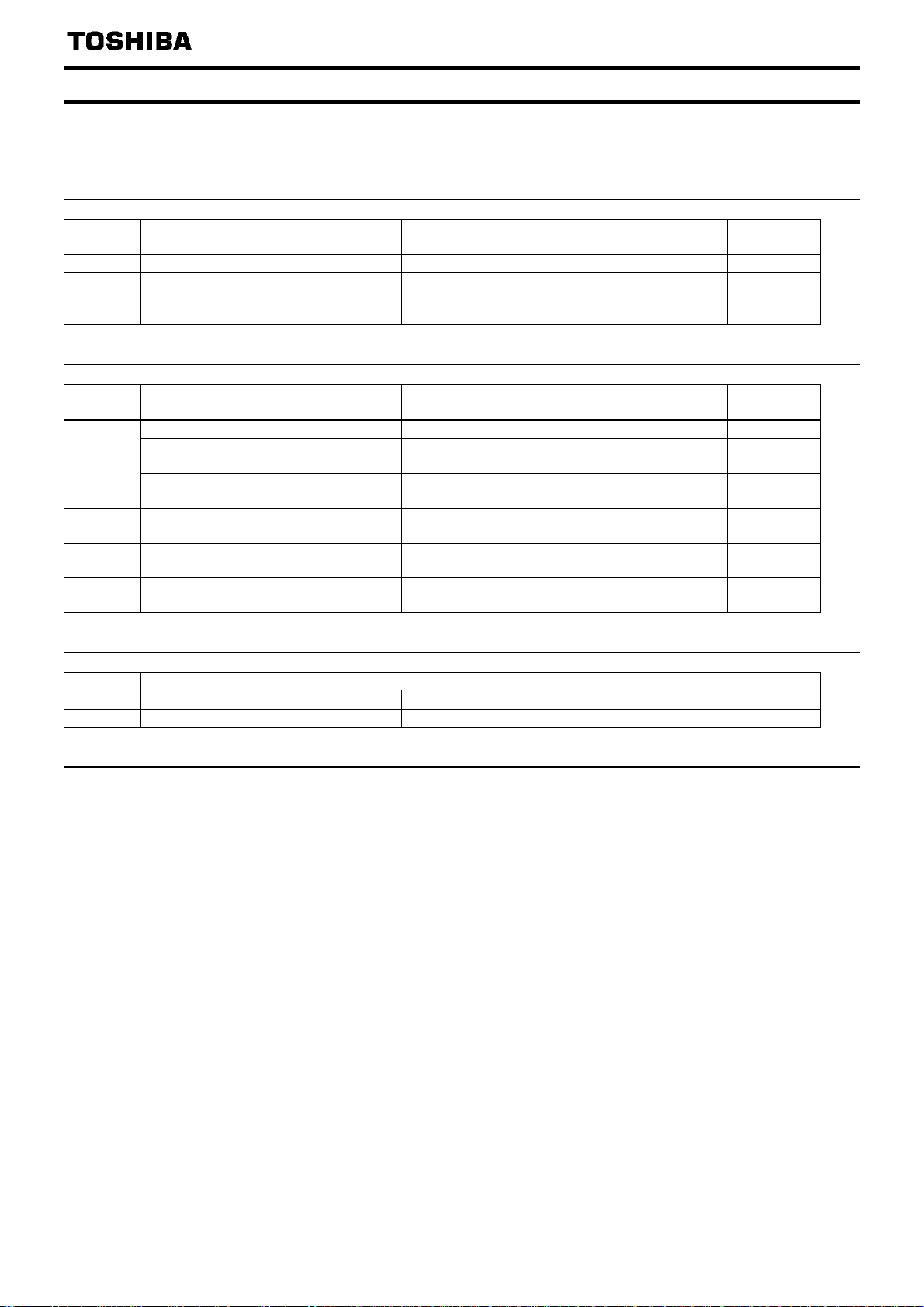
3.2. Message Router Object
Class Code 0x02. The Message Router Object provides a messaging connection point through
which a Client may address a service to any object class or instance residing in the physical
device.
3.2.1.
Attribute
3.2.2.
Attribute
3.2.3. Message Router Object Common Services
3.2.4.
Message Router Object Class Attributes
ID
1 Revision UINT Get Revision of this object 1
2 Max instance UINT Get
Name
Data
Type
ccess
Rules
Description
Maximum instance number of an object
currently created in this class level of
the device
Message Router Object Instance Attributes
ID
Object list STRUCT Get A list of supported objects -
Number UINT Get
1
Classes
2 Number available UINT Get
3 Number active UINT Get
4 Activec connections
Name
Data
Type
UINT
(ARRAY)
UINT
(ARRAY)
ccess
Rules
Number of supported classes in the
classes array
Get List of supported class codes -
Maximum number of connections
supported
Number of connections currently used
by system components
Get
A list of the connection IDs of the
currently active connections
Description
Service
Code
0x0E Get_Attribute_Single Yes Yes Returns the contents of the specified attribute.
Service Name
Supported
Class Instance
Description of Service
Message Router Object Specific Services
Message Router Object provides no object specific services.
Default
Value
1
Default
Value
11
16
-
-
- 12 -
Page 14
E6581737
A
A
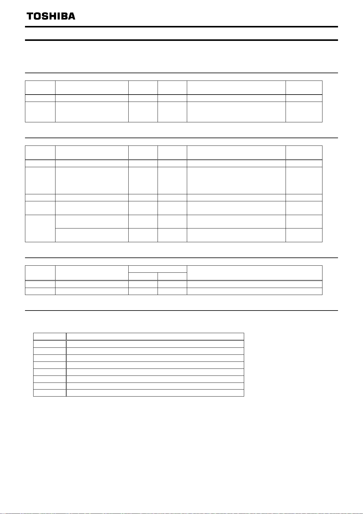
3.3. DeviceNet Object
Class Code 0x03. The DeviceNet Object provides for the configuration and status of a
DeviceNet port.
3.3.1. DeviceNet Object Class Attributes
Attribute
ID
1 Revision UINT Get Revision of this object. 2
2 Max instance UINT Get
Name
3.3.2. DeviceNet Object Instance Attributes
Attribute
ID
1 MAC ID USINT Get Node address 63
2 Baud Rate USINT Get
3 Bus-off Interrupt BOOL Get/Set Bus–Off Interrupt 0
4 Bus-off counter USINT Get/Set
Allocation information
(Allocation Choice Byte)
5
Allocation information
(Master’s MAC ID)
Name
3.3.3. DeviceNet Object Common Services
Service
Code
0x0E Get_Attribute_Single Yes Yes Returns the contents of the specified attribute.
0x10 Set_Attribute_Single N/A Yes Modifies the value of the specified attribute.
Service Name
3.3.4. DeviceNet Object Specific Services
DeviceNet Object provides no object specific services for the slave.
* Attribute 5 Allocation Choice Byte
Bit Note
0 Explicit
1 Poll
2 Bit Strobe
3 Multicast Poll
4 Change of State
5 Cyclic
6 ACK Suppression
7 (Reserved)
Data
Type
Data
Type
BYTE
USINT
Supported
Class
ccess
Rules
Maximum instance number of an object
currently created in this class level of
the device
ccess
Rules
Baud rate
0 = 125kbps
1 = 250kbps
2 = 500kbs
Number of times CAN went to
the bus-off state
Get Master/Slave allocation state * -
Get
Instance
MAC ID of Master
(from Allocate)
Description
Description
Description of Service
Default
Value
1
Default
Value
-
0
-
- 13 -
Page 15
E6581737
A
A
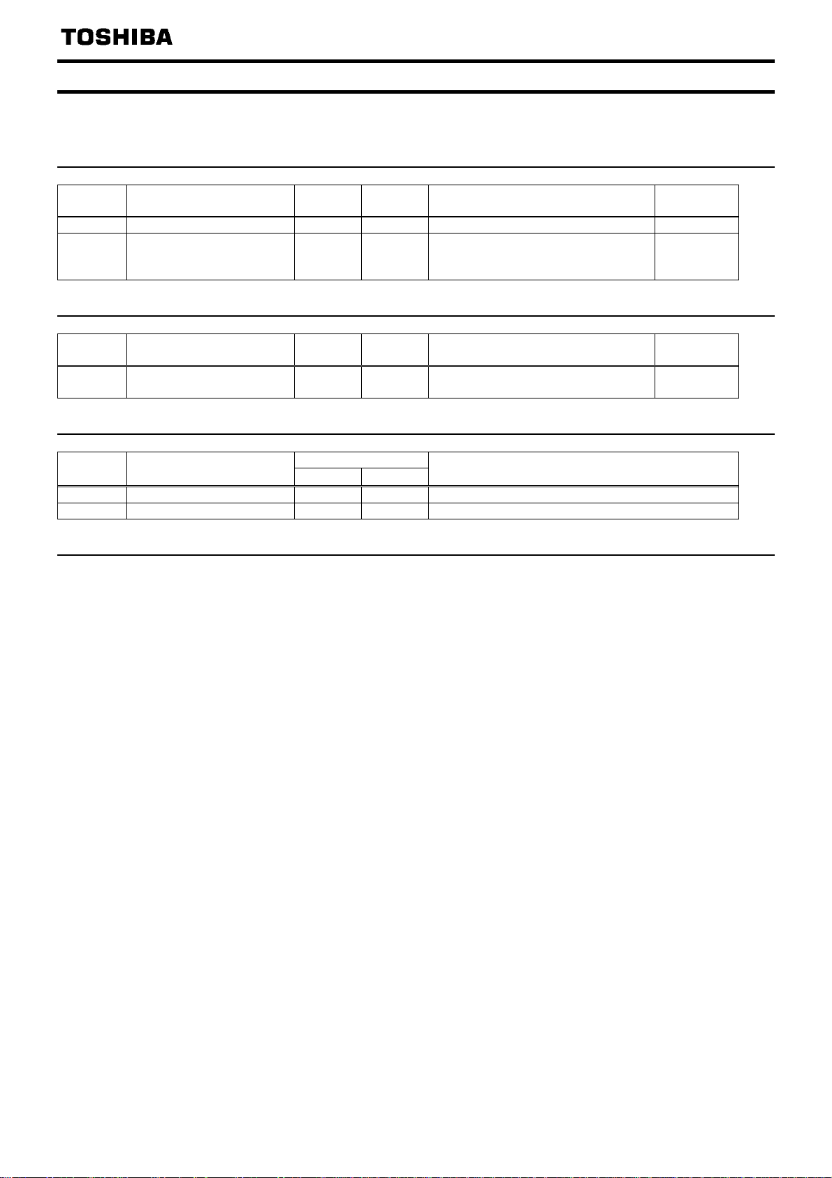
3.4. Assembly Object
Class code 0x04. The Assembly Object binds attributes of multiple objects, which allows data to
or from each object to be sent or received over a single connection.
3.4.1. Assembly Object Class Attributes
Attribute
ID
1 Revision UINT Get Revision of this object. 2
2 Max instance UINT Get
Name
3.4.2. Assembly Object Instance Attributes
Attribute
ID
3 Data
Name
3.4.3. Assembly Object Common Services
Service
Code
0x0E Get_Attribute_Single Yes Yes Returns the contents of the specified attribute.
0x10 Set_Attribute_Single N/A Yes Modifies the value of the specified attribute.
Service Name
3.4.4. Assembly Object Specific Services
Assembly Object for static assemblies provides no object specific services.
Data
Type
Data
Type
BYTE
(ARRAY)
Supported
Class Instance
ccess
Rules
ccess
Rules
Get/Set
Description
Maximum instance number of an object
currently created in this class level of
the device
Description
The data contained in the assembly
object. (Refer to section 3.4.5.)
Description of Service
Default
Value
155
Default
Value
-
- 14 -
Page 16
E6581737
3.4.5. Assembly Instance Details
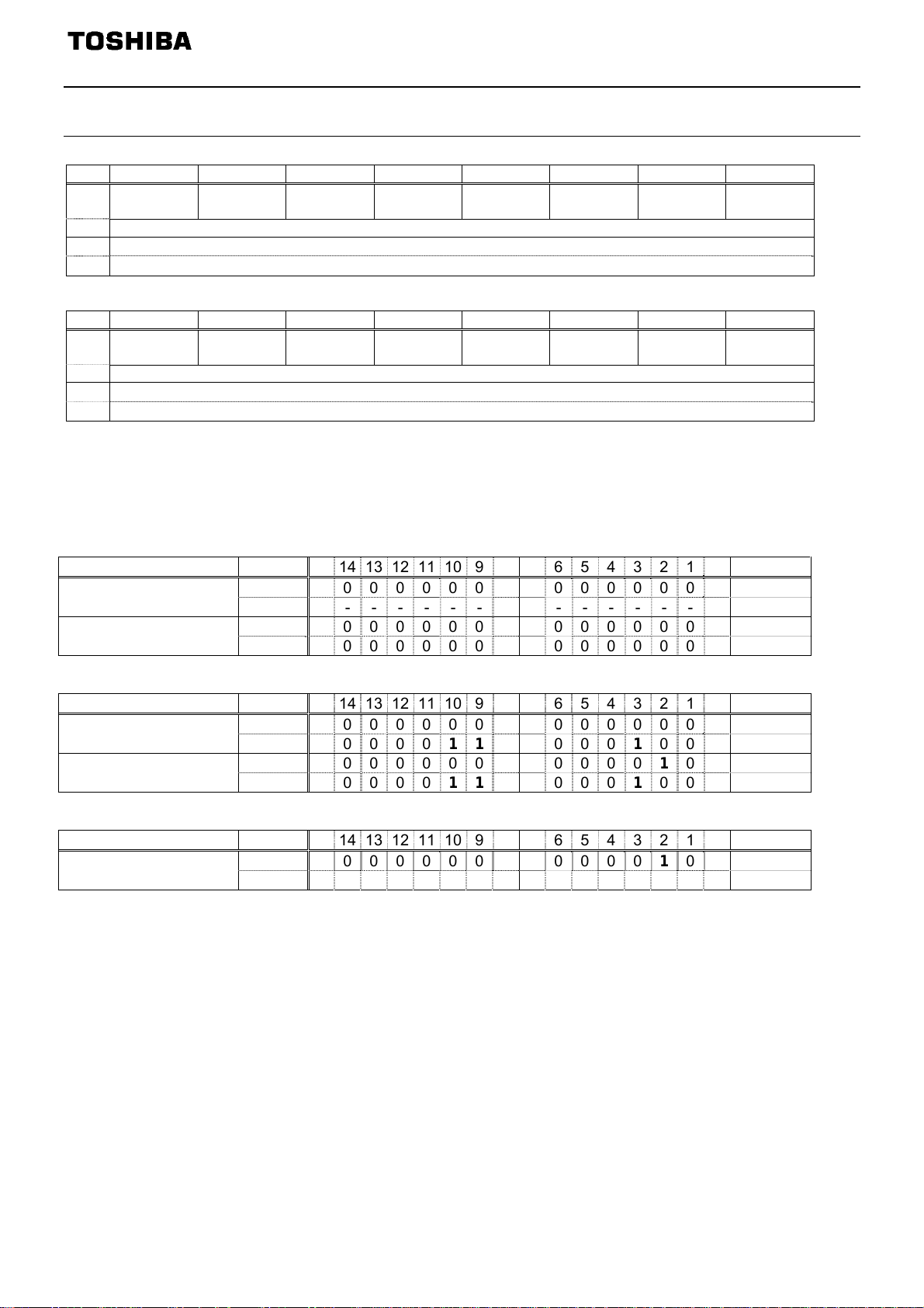
3.4.5.1. Instance 20/70 - DeviceNet Standard (4 bytes, parameter c203 = 0)
Byte Bit 7 Bit 6 Bit 5 Bit 4 Bit 3 Bit 2 Bit 1 Bit 0
0 - - - - - Fault reset -
1 2
3
Drive Reference Speed min
Drive Reference Speed min
-1
(Low byte) *
-1
(High byte) *
Run
forward
Fig. 1 Output Instance 20 Layout
Byte Bit 7 Bit 6 Bit 5 Bit 4 Bit 3 Bit 2 Bit 1 Bit 0
0 - - - - -
1 2
3
Drive Actual Speed min
Drive Actual Speed min
-1
(Low byte)
-1
(High byte)
Running
Forward
-
Faulted/
tripped
Fig. 2 Input Instance 70 Layout
* When Instance 20/70 is used, set
cmod and fmod to "Communication option".
Examples of Instance 20/70
Stop
Instance Byte 15 14 13 12 11 10 9 8 7 6 5 4 3 2 1 0 Hex.
Output Instance 20
Input Instance 70
1, 0 0 0 0 0 0 0 0 0 0 0 0 0 0 0 0 0 0x0000
3, 2 - - - - - - - - - - - - - - - - 1, 0 0 0 0 0 0 0 0 0 0 0 0 0 0 0 0 0 0x0000
3, 2 0 0 0 0 0 0 0 0 0 0 0 0 0 0 0 0 0x0000
Forward running 1800min-1
Instance Byte 15 14 13 12 11 10 9 8 7 6 5 4 3 2 1 0 Hex.
Output Instance 20
Input Instance 70
1, 0 0 0 0 0 0 0 0 0 0 0 0 0 0 0 0 1 0x0001
3, 2 0 0 0 0 0 11100001 0 0 0 0x0708
1, 0 0 0 0 0 0 0 0 0 0 0 0 0 0 1 0 0 0x0004
3, 2 0 0 0 0 0 11100001 0 0 0 0x0708
Fault reset **
Instance Byte 15 14 13 12 11 10 9 8 7 6 5 4 3 2 1 0 Hex.
Output Instance 20
Drive Reference Speed is set up number of rotations by the hexadecimal number.
*
For example, when "Frequency reference" is set up to 1800min
1800 = 0x0708 (Hex.)
** Fault reset works only 1 time when 0 -> 1.
1, 0 0 0 0 0 0 0 0 0 0 0 0 0 0 1 0 0 0x0004
3, 2 - - - - - - - - - - - - - - - - -
-1
:
- 15 -
Page 17

E6581737
3.4.5.2.
Instance 21/71 - DeviceNet Standard (4 bytes, parameter c203 = 1)
Byte Bit 7 Bit 6 Bit 5 Bit 4 Bit 3 Bit 2 Bit 1 Bit 0
0 - Net Ref * Net Ctrl * - - Fault reset
1 2
3
Drive Reference Speed min
Drive Reference Speed min
-1
(Low byte)
-1
(High byte)
Run
reverse
Run
forward
Fig. 3 Output Instance 21 Layout
Byte Bit 7 Bit 6 Bit 5 Bit 4 Bit 3 Bit 2 Bit 1 Bit 0
0
1 Drive Status ***
2
3
At
reference **
Ref from
Net **
Ctrl from
Net **
Drive Actual Speed min
Drive Actual Speed min
Ready
Running
Reverse
-1
(Low byte)
-1
(High byte)
Running
Forward
Warning
Faulted/
tripped
Fig. 4 Input Instance 71 Layout
* Bit 5 and 6 of the instance 21 byte 0 are defined as follows.
Bit 5 (Net Ctrl) ................. When “1” is set, bits 0 (Run forward) and 1 (Run reverse) of byte 0 are enabled. When
“0” is set, Run/Stop is according to setup of the VF-MB1/S15 parameter cmod.
Bit 6 (Net Ref) ................. When “1” is set, Drive Reference Speed is according to the value of bytes 2 and 3.
When “0” is set, Drive Reference Speed is according to setup of the VF-MB1/S15
parameter fmod.
** Bit 5, 6, and 7 of the instance 71 byte 0 are defined as follows.
Bit 5 (Ctrl from Net)......... When RUN/STOP command from DeviceNet is enabled, “1” is set.
Bit 6 (Ref from Net)......... When frequency command from DeviceNet is enabled, “1” is set.
Bit 7 (At reference) ......... When output frequency becomes the same as frequency command, “1” is set.
*** Drive Status is same as the Control Supervisor class State attribute (refer to section 3.7.2).
1 (00000001): Startup
2 (00000010): Not Ready
3 (00000011): Ready
4 (00000100): Enabled
5 (00000101): Stopping
6 (00000110): Fault Stop
7 (00000111): Faulted
- 16 -
Page 18
E6581737
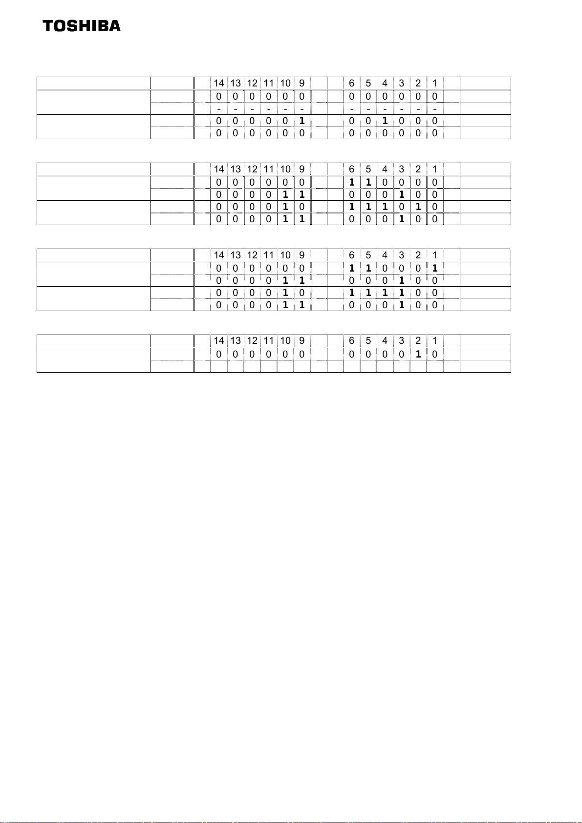
Examples of Instance 21/71
Stop
Instance Byte 15 14 13 12 11 10 9 8 7 6 5 4 3 2 1 0 Hex.
Output Instance 21
Input Instance 71
Forward running 1800min
Instance Byte 15 14 13 12 11 10 9 8 7 6 5 4 3 2 1 0 Hex.
Output Instance 21
Input Instance 71
Reverse running 1800min
Instance Byte 15 14 13 12 11 10 9 8 7 6 5 4 3 2 1 0 Hex.
Output Instance 21
Input Instance 71
1, 0 0 0 0 0 0 0 0 0 0 0 0 0 0 0 0 0 0x0000
3, 2 - - - - - - - - - - - - - - - - -
1, 0 0 0 0 0 0 0 110001 0 0 0 0 0x0310
3, 2 0 0 0 0 0 0 0 0 0 0 0 0 0 0 0 0 0x0000
-1
1, 0 0 0 0 0 0 0 0 0 0 110 0 0 0 1 0x0061
3, 2 0 0 0 0 0 11100001 0 0 0 0x0708
1, 0 0 0 0 0 0 1 0011110 1 0 0 0x04F4
3, 2 0 0 0 0 0 11100001 0 0 0 0x0708
-1
1, 0 0 0 0 0 0 0 0 0 0 11000 1 0 0x0062
3, 2 0 0 0 0 0 11100001 0 0 0 0x0708
1, 0 0 0 0 0 0 1 00111110 0 0 0x04F8
3, 2 0 0 0 0 0 11100001 0 0 0 0x0708
Fault reset *
Instance Byte 15 14 13 12 11 10 9 8 7 6 5 4 3 2 1 0 Hex.
Output Instance 21
* Fault reset works only 1 time when 0 -> 1.
1, 0 0 0 0 0 0 0 0 0 0 0 0 0 0 1 0 0 0x0004
3, 2 - - - - - - - - - - - - - - - - -
- 17 -
Page 19
E6581737
3.4.5.3.
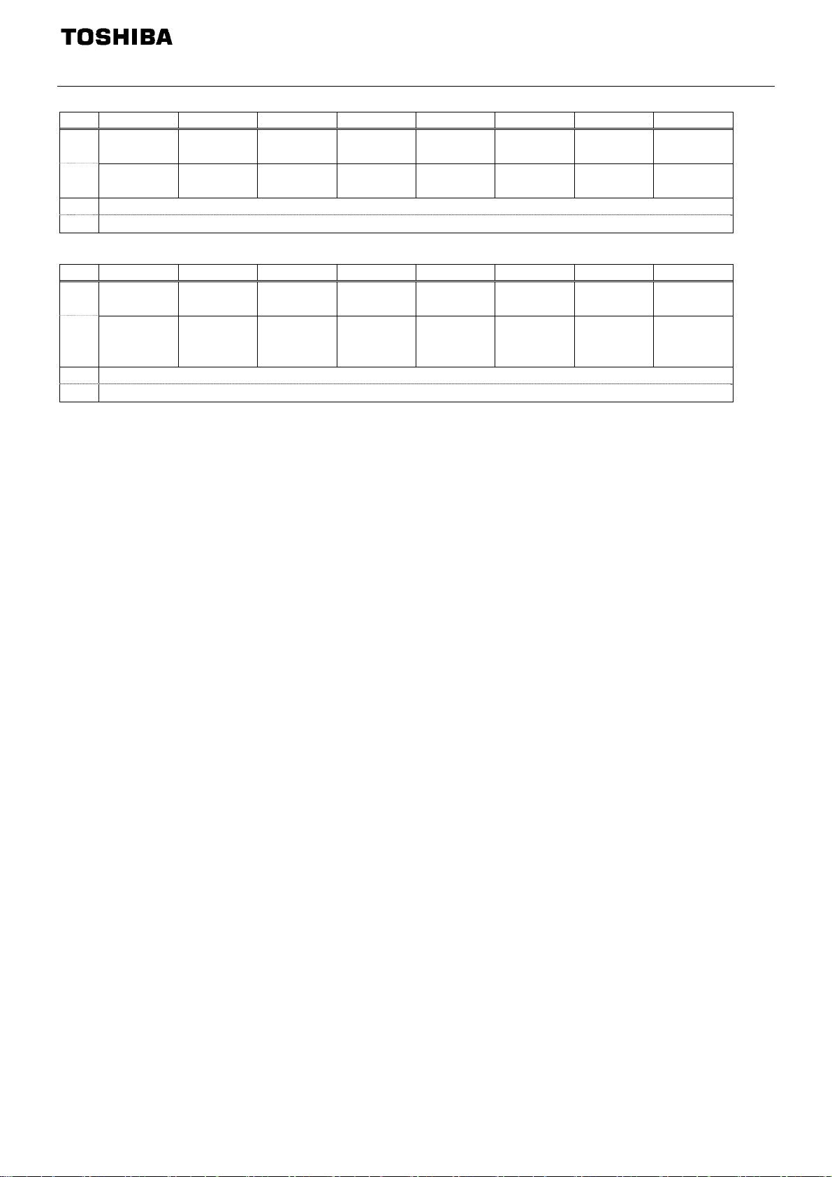
Instance 100/150 - Toshiba Specific (4 bytes, parameter c203 = 2)
Byte Bit 7 Bit 6 Bit 5 Bit 4 Bit 3 Bit 2 Bit 1 Bit 0
0
1
2
3
DC braking
Command
link *
ACC1/
ACC2
Frequency
link *
PI off THR2
Reset trip
Emergency
stop
Drive Reference Speed Hz (Low byte) **
Drive Reference Speed Hz (High byte) **
Preset
Speed4
Free run
(ST)
Preset
Speed3
Run/stop
Preset
Speed2
Forward/
Reverse
Preset
Speed1
Jog
Fig. 5 Output Instance 100 Layout
Byte Bit 7 Bit 6 Bit 5 Bit 4 Bit 3 Bit 2 Bit 1 Bit 0
0
DC braking ACC2 PI
READY
1
2
3
-
without
ST/RUN
READY
with
ST/ RUN
THR 2
(VF2+tH2)
Emergency
stop
Drive Actual Speed Hz (Low byte)
Drive Actual Speed Hz (High byte)
-
Free run
(ST)
ALARM
(fc91)
Run/Stop
EMG FL
Forward /
Reverse
Jog
Fig. 6 Input Instance 150 Layout
* Bit 7 and 6 of the instance 100 byte 1 are defined as follows.
Bit 7 (Command link) ...... When “0” is set, the other command does not work except bit 4 and 3 of instance 100
byte 1, Run/Stop is according to setup of the VF-MB1/S15 parameter
cmod.
Bit 6 (Frequency link)...... When “1” is set, Drive Reference Speed is according to the value of bytes 2 and 3.
When “0” is set, Drive Reference Speed is according to setup of the VF-MB1/S15
parameter
fmod.
Drive Reference Speed is set up by 0.01Hz unit and the hexadecimal number.
**
For example, when "Frequency reference" is set up to 60Hz, since the minimum unit is 0.01Hz,
60 / 0.01 = 6000 = 0x1770 (Hex.)
- 18 -
Page 20
E6581737
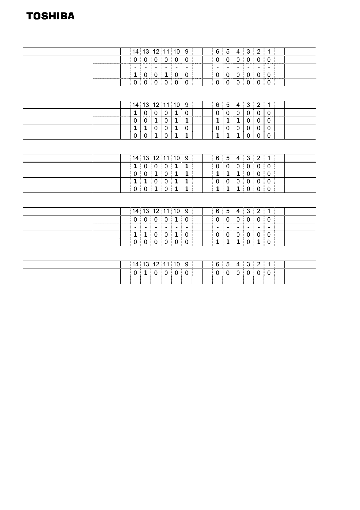
Examples of Instance 100/150
Stop
Instance Byte 15 14 13 12 11 10 9 8 7 6 5 4 3 2 1 0 Hex.
Output Instance 100
Input Instance 150
1, 0 0 0 0 0 0 0 0 0 0 0 0 0 0 0 0 0 0x0000
3, 2 - - - - - - - - - - - - - - - - -
1, 0 0 1 0 0 1 0 0 0 0 0 0 0 0 0 0 0 0x4800
3, 2 0 0 0 0 0 0 0 0 0 0 0 0 0 0 0 0 0x0000
Forward running 60Hz
Instance Byte 15 14 13 12 11 10 9 8 7 6 5 4 3 2 1 0 Hex.
Output Instance 100
Input Instance 150
1, 0 1 1 0 0 0 1 0 0 0 0 0 0 0 0 0 0 0xC400
3, 2 0 0 0 1 0 1110 1110 0 0 0 0x1770
1, 0 0 1 1 001 0 0 0 0 0 0 0 0 0 0 0x6400
3, 2 0 0 0 1 0 1110 1110 0 0 0 0x1770
Reverse running 60Hz
Instance Byte 15 14 13 12 11 10 9 8 7 6 5 4 3 2 1 0 Hex.
Output Instance 100
Input Instance 150
1, 0 1 1 0 0 0 110 0 0 0 0 0 0 0 0 0xC600
3, 2 0 0 0 1 0 1110 1110 0 0 0 0x1770
1, 0 0 1 1 00110 0 0 0 0 0 0 0 0 0x6600
3, 2 0 0 0 1 0 1110 1110 0 0 0 0x1770
Preset speed 1 with forward running (sr1)
Instance Byte 15 14 13 12 11 10 9 8 7 6 5 4 3 2 1 0 Hex.
Output Instance 100
Input Instance 150 1, 0 0 1 1 001 0 0 0 0 0 0 0 0 0 0 0x6400
(sr1 is 5Hz.) 3, 2 0 0 0 0 0 0 0 111110 1 0 0 0x01F4
1, 0 1 0 0 0 0 1 00000000 0 1 0x8401
3, 2 - - - - - - - - - - - - - - - - -
Fault reset *
Instance Byte 15 14 13 12 11 10 9 8 7 6 5 4 3 2 1 0 Hex.
Output Instance 100
About the other command, refer to section エラー! 参照元が見つかりません。.
* Fault reset works only 1 time when 0 -> 1.
1, 0 0 0 1 0 0 0 0 0 0 0 0 0 0 0 0 0 0x2000
3, 2 - - - - - - - - - - - - - - - - -
- 19 -
Page 21
E6581737
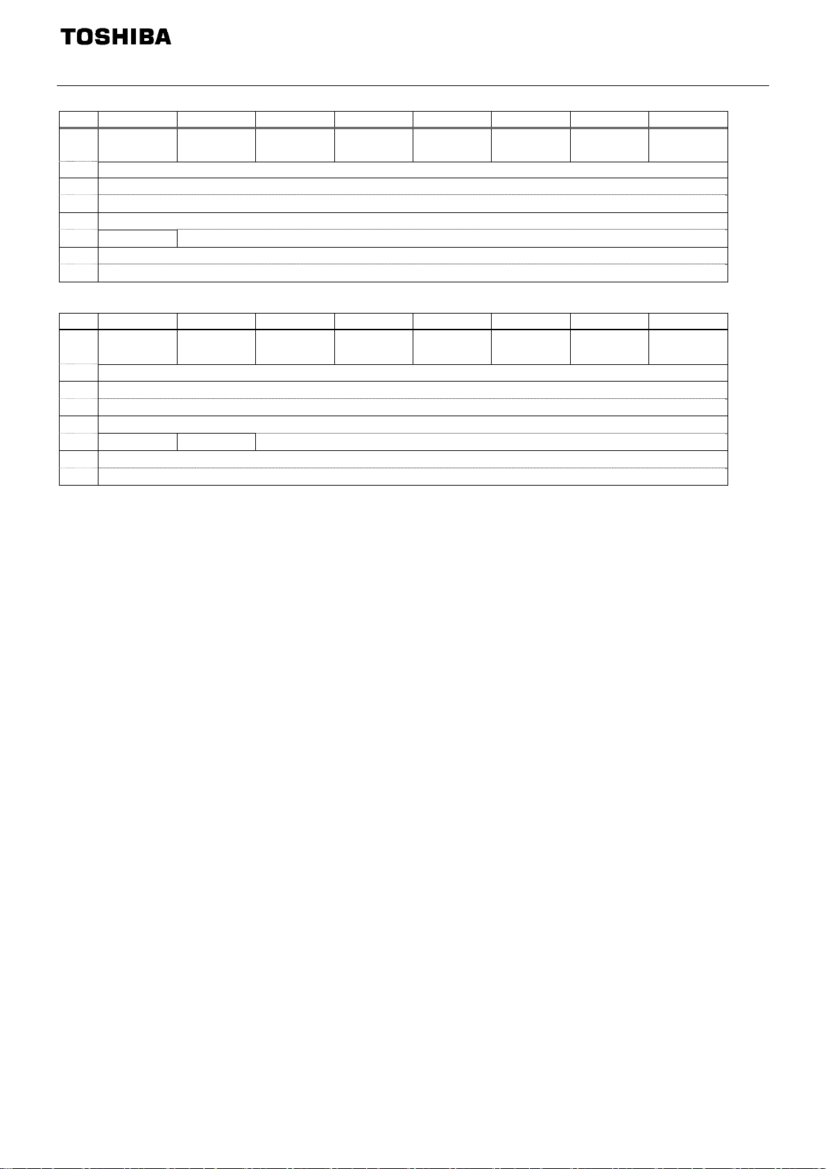
3.4.5.4.
Instance 101/151 - Toshiba Specific (8 bytes, parameter c203 = 3)
Byte Bit 7 Bit 6 Bit 5 Bit 4 Bit 3 Bit 2 Bit 1 Bit 0
0
1 2
3
4
5
6
7
-
Write Index (High byte)
Net Ref * Net Ctrl *
Drive Reference Speed min
Drive Reference Speed min
- - Fault reset
-1
(Low byte)
-1
(High byte)
Index (Low byte)
Data (Low byte)
Data (High byte)
Run
reverse
Run
forward
Fig. 7 Output Instance 101 Layout
Byte Bit 7 Bit 6 Bit 5 Bit 4 Bit 3 Bit 2 Bit 1 Bit 0
0
1
2
3
4
5
6
7
At
reference **
Write Error Index (High byte)
Ref from
Net **
Ctrl from
Net **
Drive Actual Speed min
Drive Actual Speed min
Ready
Drive Status ***
Index (Low byte)
Data (Low byte)
Data (High byte)
Running
Reverse
-1
(Low byte)
-1
(High byte)
Running
Forward
Warning
Faulted/
tripped
Fig. 8 Input Instance 151 Layout
* Bit 5 and 6 of the instance 101 byte 0 are defined as follows.
Bit 5 (Net Ctrl) ................. When “1” is set, bits 0 (Run forward) and 1 (Run reverse) of byte 0 are enabled. When
“0” is set, Run/Stop is according to setup of the VF-MB1/S15 parameter cmod.
Bit 6 (Net Ref) ................. When “1” is set, Drive Reference Speed is according to the value of bytes 2 and 3.
When “0” is set, Drive Reference Speed is according to setup of the VF-MB1/S15
parameter fmod.
** Bit 5, 6, and 7 of the instance151 byte 0 are defined as follows.
Bit 5 (Ctrl from Net)......... When RUN/STOP command from DeviceNet is enabled, “1” is set.
Bit 6 (Ref from Net)......... When frequency command from DeviceNet is enabled, “1” is set.
Bit 7 (At reference) ......... When output frequency becomes the same as frequency command, “1” is set.
*** Drive Status is same as the Control Supervisor class State attribute (refer to 3.7.2).
1 (00000001): Startup
2 (00000010): Not Ready
3 (00000011): Ready
4 (00000100): Enabled
5 (00000101): Stopping
6 (00000110): Fault Stop
7 (00000111): Faulted
- 20 -
Page 22
E6581737
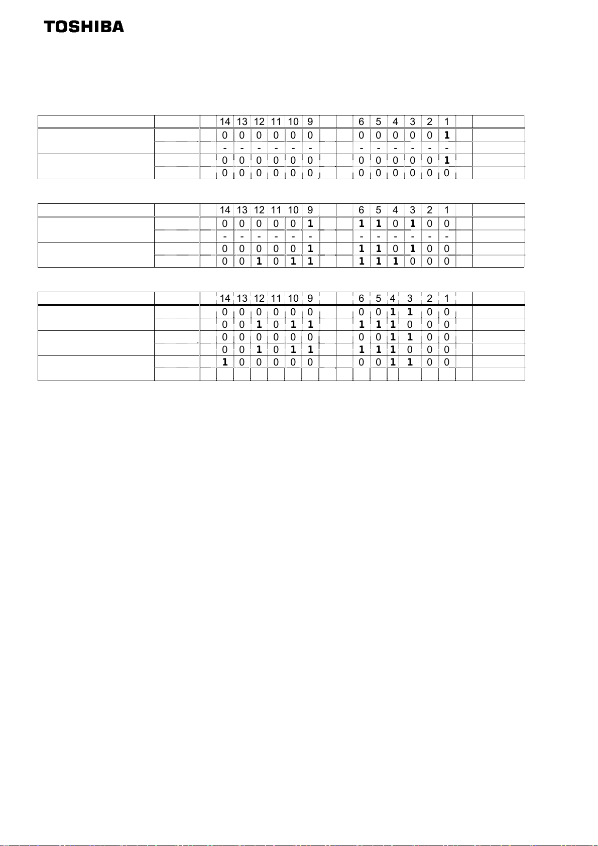
Examples of Instance 101/151
Access the inverter parameter is enabled using byte 4 to 7 of this Instance.
Set the communication number of the parameter to byte 4, 5 (Index), and the value to byte 6, 7 (Data).
Read the parameter cmod (Command mode selection, communication number is 0003).
Instance Byte 15 14 13 12 11 10 9 8 7 6 5 4 3 2 1 0 Hex.
Output Instance 101
Input Instance 151 5, 4 0 0 0 0 0 0 0 0 0 0 0 0 0 0 1 1 0x0003
(cmod is 0.) 7, 6 0 0 0 0 0 0 0 0 0 0 0 0 0 0 0 0 0x0000
5, 4 0 0 0 00000000000 1 1 0x0003
7, 6 - - - - - - - - - - - - - - - - -
Read the parameter f268 (Initial value of UP/DOWN frequency).
Instance Byte 15 14 13 12 11 10 9 8 7 6 5 4 3 2 1 0 Hex.
Output Instance 101
Input Instance 151 5, 4 0 0 0 0 0 0 1 00110 1 0 0 0 0x0268
(f268 is 60.0Hz.) 7, 6 0 0 0 1 0 1110 1110 0 0 0 0x1770
5, 4 0 0 0 0 0 0 1 00110 1 0 0 0 0x0268
7, 6 - - - - - - - - - - - - - - - - -
Write “60 (Hz)” to the parameter sr1 (Preset speed 1, communication number is 0018).
Instance Byte 15 14 13 12 11 10 9 8 7 6 5 4 3 2 1 0 Hex.
Output Instance 101
Input Instance 151 (OK)
Input Instance 151 (NG) 5, 4 1 1 0 0000000011 0 0 0 0xC018
(Error code *) 7, 6 0 0 0 1 0001 00000 0 0 1 0x1101
About byte 0 - 3, refer to section 3.4.5.2.
* Refer to following about the error code.
0x1100: Data out of range
0x1101: Bad address
5, 4 1 0 0 0000000011 0 0 0 0x8018
7, 6 0 0 0 1 0 1110 1110 0 0 0 0x1770
5, 4 1 0 0 0000000011 0 0 0 0x8018
7, 6 0 0 0 1 0 1110 1110 0 0 0 0x1770
- 21 -
Page 23
E6581737
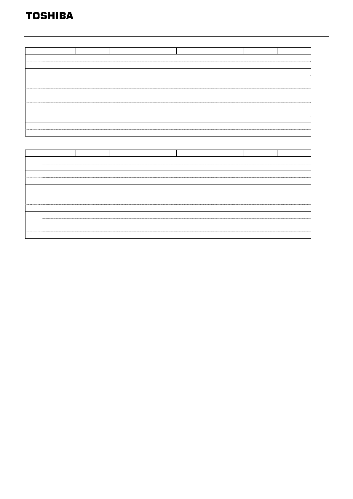
3.4.5.5.
Instance 102/152 - Toshiba Specific (12 bytes, parameter c203 = 4)
Byte Bit 7 Bit 6 Bit 5 Bit 4 Bit 3 Bit 2 Bit 1 Bit 0
0 c001 Command data (Low byte)
1 c001 Command data (High byte)
2 c002 Command data (Low byte)
3 c002 Command data (High byte)
4 c003 Command data (Low byte)
5 c003 Command data (High byte)
6 c004 Command data (Low byte)
7 c004 Command data (High byte)
8 c005 Command data (Low byte)
9 c005 Command data (High byte)
10 c006 Command data (Low byte)
11 c006 Command data (High byte)
Fig. 9 Output Instance 102 Layout
Byte Bit 7 Bit 6 Bit 5 Bit 4 Bit 3 Bit 2 Bit 1 Bit 0
0 c021 Monitor data (Low byte)
1 c021 Monitor data (High byte)
2 c022 Monitor data (Low byte)
3 c022 Monitor data (High byte)
4 c023 Monitor data (Low byte)
5 c023 Monitor data (High byte)
6 c024 Monitor data (Low byte)
7 c024 Monitor data (High byte)
8 c025 Monitor data (Low byte)
9 c025 Monitor data (High byte)
10 c026 Monitor data (Low byte)
11 c026 Monitor data (High byte)
Fig. 10 Input Instance 152 Layout
About byte 0 - 11, refer to section 3.4.5.7.
- 22 -
Page 24
E6581737
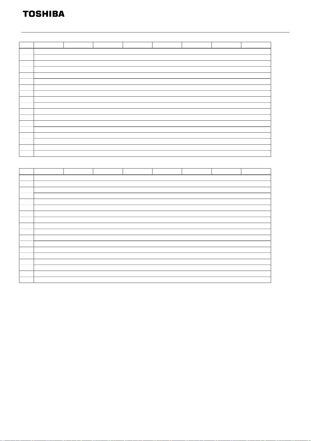
3.4.5.6.
Instance 105/155 - Toshiba Specific (18 bytes, parameter c203 = 5)
Byte Bit 7 Bit 6 Bit 5 Bit 4 Bit 3 Bit 2 Bit 1 Bit 0
0 1 Read/Write command
2 Index (Low byte)
3 Index (High byte)
4 Data (Low byte)
5 Data (High byte)
6 c001 Command data (Low byte)
7 c001 Command data (High byte)
8 c002 Command data (Low byte)
9 c002 Command data (High byte)
10 c003 Command data (Low byte)
11 c003 Command data (High byte)
12 c004 Command data (Low byte)
13 c004 Command data (High byte)
14 c005 Command data (Low byte)
15 c005 Command data (High byte)
16 c006 Command data (Low byte)
17 c006 Command data (High byte)
Fig. 11 Output Instance 105 Layout
Byte Bit 7 Bit 6 Bit 5 Bit 4 Bit 3 Bit 2 Bit 1 Bit 0
0 -
1 Read/Write response *
2 Index (Low byte)
3 Index (High byte)
4 Data (Low byte)
5 Data (High byte)
6 c021 Monitor data (Low byte)
7 c021 Monitor data (High byte)
8 c022 Monitor data (Low byte)
9 c022 Monitor data (High byte)
10 c023 Monitor data (Low byte)
11 c023 Monitor data (High byte)
12 c024 Monitor data (Low byte)
13 c024 Monitor data (High byte)
14 c025 Monitor data (Low byte)
15 c025 Monitor data (High byte)
16 c026 Monitor data (Low byte)
17 c026 Monitor data (High byte)
Fig. 12 Input Instance 155 Layout
About byte 6 - 17, refer to section 3.4.5.7.
- 23 -
Page 25
E6581737
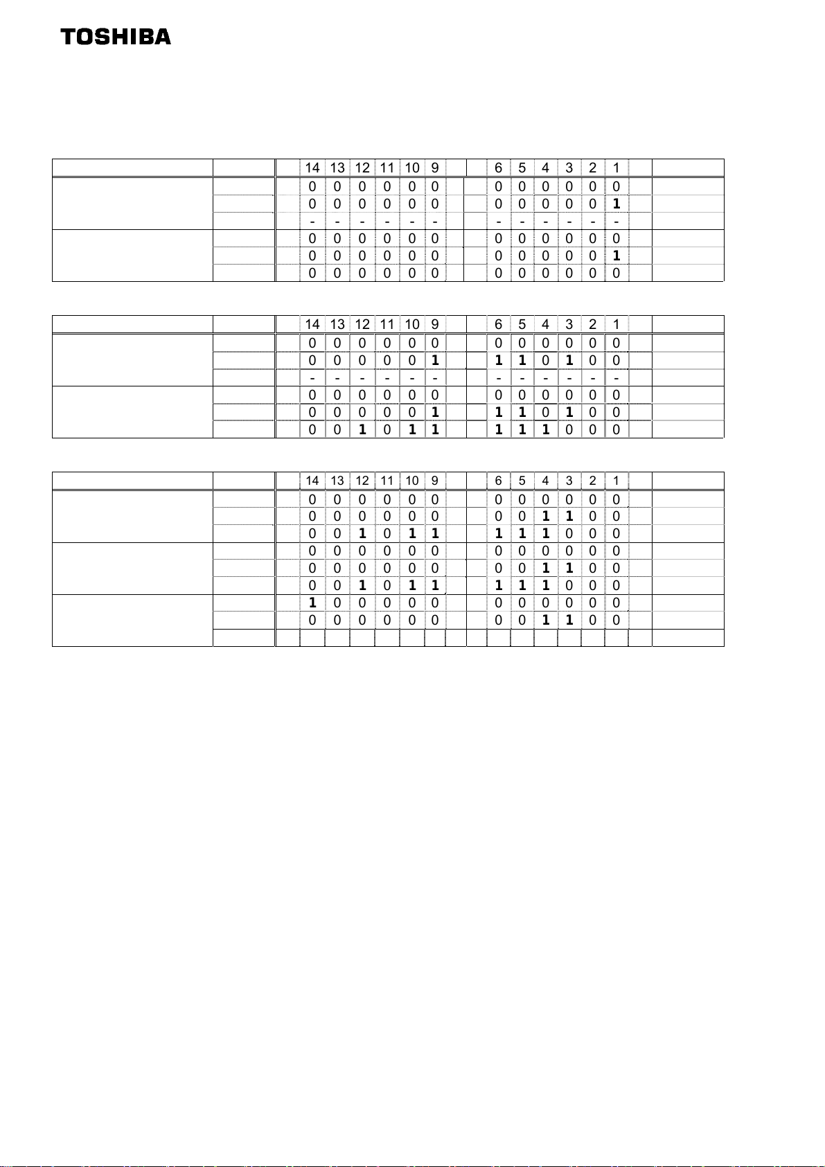
Examples of Instance 105/155
Access the inverter parameter is enabled using byte 1 to 5 of this Instance.
Set the communication number of the parameter to byte 2, 3 (Index), and the value to byte 4, 5 (Data).
Read the parameter cmod (Command mode selection, communication number is 0003).
Instance Byte 15 14 13 12 11 10 9 8 7 6 5 4 3 2 1 0 Hex.
1, 0 0 0 000000000000 0 0 0x0000
Output Instance 105
Input Instance 155
cmod is 0.)
(
3, 2 0 0 000000000000 1 1 0x0003
5, 4 - - - - - - - - - - - - - - - - 1, 0 0 0 000000000000 0 0 0x0000
3, 2 0 0 000000000000 1 1 0x0003
5, 4 0 0 000000000000 0 0 0x0000
Read the parameter f268 (Initial value of UP/DOWN frequency).
Instance Byte 15 14 13 12 11 10 9 8 7 6 5 4 3 2 1 0 Hex.
1, 0 0 0 000000000000 0 0 0x0000
Output Instance 105
Input Instance 155
f268 is 60.0Hz.)
(
3, 2 0 0 00001 00110 1 0 0 0 0x0268
5, 4 - - - - - - - - - - - - - - - - 1, 0 0 0 000000000000 0 0 0x0000
3, 2 0 0 00001 00110 1 0 0 0 0x0268
5, 4 0 0 0 1 0 1110 1110 0 0 0 0x1770
Write “60 (Hz)” to the parameter sr1 (Preset speed 1, communication number is 0018).
Instance Byte 15 14 13 12 11 10 9 8 7 6 5 4 3 2 1 0 Hex.
1, 0 1 0 000000000000 0 0 0x8000
Output Instance 105
Input Instance 155
(OK)
Input Instance 155
(NG)
(Error code *)
*Data of "Error code"
0x0001: Error
3, 2 0 0 000000000110 0 0 0x0018
5, 4 0 0 0 1 0 1110 1110 0 0 0 0x1770
1, 0 0 0 000000000000 0 0 0x0000
3, 2 0 0 000000000110 0 0 0x0018
5, 4 0 0 0 1 0 1110 1110 0 0 0 0x1770
1, 0 0 1 000000000000 0 0 0x4000
3, 2 0 0 000000000110 0 0 0x0018
5, 4 0 0 000000000000 0 1 0x0001
- 24 -
Page 26
E6581737
3.4.5.7.
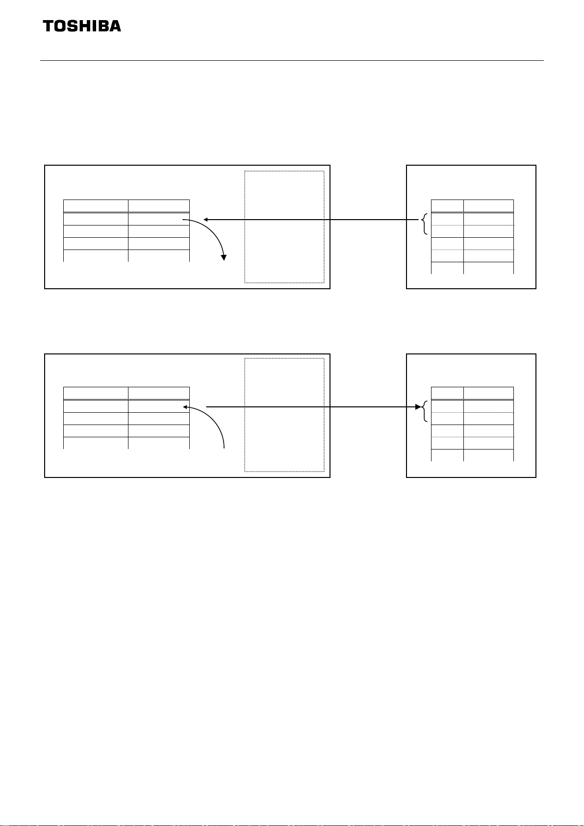
How to use Instance 102/152, 105/155
The purposes of instances 102/152 (Byte 0 - 11) and 105/155 (Byte 6 - 17) are adjustment by real time command
transmission, and the monitor of an operation state by using cyclic communication of DeviceNet.
Example 1: Command transmitting by the output Instance 102.
When you want to set "0xC400" to parameter
And Since 0 and 1 byte of the output instance 102 supports the parameter
"0xC400" will be set as
fa06.
fa06, set “1 (fa06)” to parameter c001.
c001, if "0xC400" is set up here,
VF-MB1
DEV003Z
Parameter Value
c001 1 (FA06)
c002 ...
c003 ...
... ...
"0xC400" is set as parameter fa06
DeviceNet Master
Output Instance 102
Byte Value
0 00
1 C4
2 ...
3 ...
... ...
Example 2: State monitoring by the input instance 152.
When you want to monitor the output current, set “3 (fd03)” to parameter
The value of the parameter
fd03 specified as 0 and1 byte of the input instance 152 with the parameter c021
c021.
is inputted.
VF-MB1
Parameter Value
c021 3 (fd03)
c022 ...
c023 ...
... ...
The value of a parameter
fd03(ex.0x1234)outputted.
DEV003Z
DeviceNet Master
Input Instance 152
Byte Value
0 34
1 12
2 ...
3 ...
... ...
- 25 -
Page 27

E6581737
c001 - c006 setup value c021 - c026 setup value
0: No action
1: fa06 (Communication command 1)
2: fa23 (Communication command 2)
3: fa07 (Frequency command, 0.01Hz)
5: fa50 (Terminal output data)
6: fa51 (FM analog output)
8: f601 (Stall prevention level, %)
13: acc (Acceleration time 1, 0.1s)*
14: dec (Deceleration time 1, 0.1s)*
15: ul (Upper limit, 0.01Hz)
16: vb (Torque boost value 1, 0.1%)
17: vlv (Base frequency voltage 1, 0.1V)
0: No action
1: fd01 (Status information 1)
2: fd00 (Output frequency, 0.01Hz)
3: fd03 (Output current, 0.01%)
4: fd05 (Output voltage, 0.01%)
5: fc91 (Alarm information)
6: fd22 (PID feedback value, 0.01Hz)
7: fd06 (Input terminal board status)
8: fd07 (Output terminal status)
9: fe36 (VIB input, 0.01%)
10: fe35 (VIA input, 0.01%)
11: fe37 (VIC input, 0.01%)
12: fd04 (Input voltage (DC detection), 0.01%)
13: fd16 (Estimated speed (real-time value), 0.01Hz)
14: fd18 (Torque, 0.01%)
19: f880 (Free notes)
20: fd29 (Input power, 0.01kW)
21: fd30 (Output power, 0.01kW)
22: fe14 (Cumulative operation time, hour)
23: fe40 (FM terminal output monitor, 0.01%)
25: fd20 (Torque current, 0.01%)
26: fd23 (Motor overload factor, 0.01%)
27:
fd24 (Drive overload factor, 0.01%)
28: fd25 (PBR overload factor, %)
29: fd26 (Motor load factor, %)
30: fd27 (Drive load factor, %)
31: fe56 (Pulse train input, pps)
32: fe70 (Drive rated current, 0.1A)
33: fe76 (Input W
34: fe77 (Output Watt-hour, 0.1kWh 10
35: fd83 (IGBT temperature, degree C)
*1 The unit of acc, dec is according to the parameter f519.
*2 The unit of
fe76, fe77 is according to the parameter f749.
att-hour, 0.1kWh 10
f749
f749
)
)
- 26 -
Page 28
E6581737
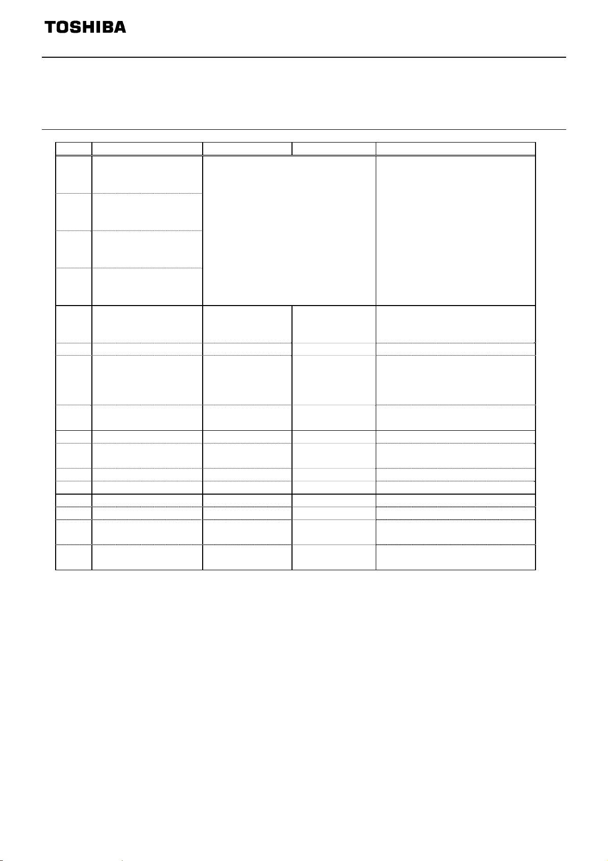
3.4.6. The outline of the parameter c001 - c006, c021 - c026 setup value
The outline is indicated about the setting item of parameter c001 - c006 and c021 - c026 in Instance
102/152 and 105/155 of use.
Please refer to a communication functional description (E6581726/E6581913) for details.
3.4.6.1.
fa06 (Communication command1)
bit Function 0 1 Note
Preset speed
0
operation frequencies
1
Preset speed
1
operation frequencies
2
Preset speed
2
operation frequencies
3
Preset speed
3
operation frequencies
Preset speed operation is disabled
or preset speed operation
frequencies (1-15) are set by
specifying bits for preset speed
operation frequencies 1-4.
(0000: Preset speed operation OFF,
001-1111: Setting of preset speed
operation frequencies (1-15)
4
Motor selection (1 or 2)
4
(THR 2 selection)
Motor 1
(THR 1)
Motor 2
(THR 2)
THR 1: pt = setting value, thr
THR 2: pt = 0, f170,
f171, f172, f173
5 PI D control Normal operation PI D off -
Acceleration/deceleration pattern selection
6
(1 or 2)
(AD2 selection)
Acceleration/decel
eration pattern 1
(AD1)
7 DC braking OFF
Acceleration/dec
eleration pattern
2
(AD2)
Forced DC
braking
AD1: acc, dec
AD2: f500, f501
-
8 Jog run OFF Jog run -
Forward/reverse run
9
selection
Forward run Reverse run -
10 Run/stop Stop Run 11 Coast stop command Standby Cost stop 12 Emergency stop OFF Emergency stop Always enable, "E" trip
13 Fault reset OFF Reset No data is returned from the drive
Frequency priority
14
selection
Command priority
15
selection
OFF Enabled
OFF Enabled
Enabled regardless of the setting
of fmod
Enabled regardless of the setting
of cmod
* VF-S15:When 14(sr0) is set to fmod, preset speed operation frequency 0 is selected.
- 27 -
Page 29
E6581737
3.4.6.2.
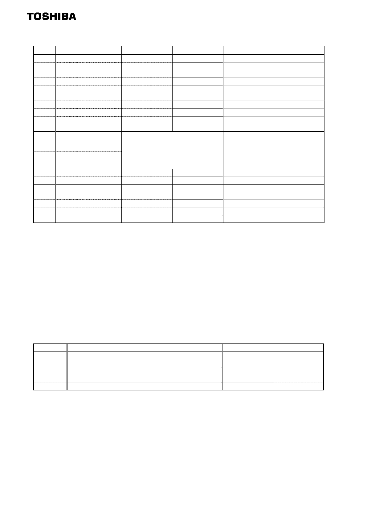
fa23 (Communication command 2)
bit Function 0 1 Note
0 (Reserved) - - -
Electric power quantity
1
reset
OFF Reset
Electric power quantity (fe76,
fe77) reset
2 (Reserved) - - 3 (Reserved) - - 4 (Reserved) - - 5 (Reserved) - - 6 (Reserved) - - -
Maximum deceleration
7
forced stop
Acceleration/decele-
8
ration selection 1
Acceleration/decele-
9
ration selection 2
Normal Enabled -
Select acceleration/deceleration
00: Acceleration/deceleration 1
01: Acceleration/deceleration 2
10: Acceleration/deceleration 3
1-4 by combination of two bits..
AD1: acc, dec
AD2: f500, f501
AD3: f510, f511
10 (Reserved) - - 11 (Reserved) - - -
12 OC stall level switch OC stall 1 OC stall 2
OC stall 1: f601
OC stall 2: f185
13 (Reserved) - - 14 (Reserved) - - 15 (Reserved) - - -
Note: Set 0 to reserved bit.
3.4.6.3.
fa07 (frequency reference from internal option)
Frequency reference is set up by 0.01Hz unit and the hexadecimal number.
For example, when "Frequency reference" is set up to 80Hz, since the minimum unit is 0.01Hz,
80 / 0.01 = 8000 = 0x1F40 (Hex.)
3.4.6.4.
fa50 (Terminal output data from communication)
By setting up the data of the bit 0 - 1 of terminal output data (fa50) from communication, setting data (OFF or
ON) can be outputted to the output terminal.
Please select the functional number 92 - 95 as the selection (f130 - f138) of the output terminal function
before using it.
bit Output TB function name 0 1
0
1
2-15 (Reserved) - -
Specified data output 1
(Output terminal No.: 92, 93)
Specified data output 2
(Output terminal No.: 94, 95)
OFF ON
OFF ON
Note: Set 0 to reserved bit
3.4.6.5.
fa51 (Analog output (FM) data from communication)
Use this function, set the FM terminal meter selection parameter (fmsl) to 18 (communication data output).
This makes it possible to send out the data specified as FM analog output data (fa51) though the FM analog
output terminal. Data can be adjusted in a range of 0 to 1000 (resolution of 10 bit).
Please refer to "Meter setting and adjustment" Section of the VF-MB1/S15 instruction manual for details.
- 28 -
Page 30
E6581737
3.4.6.6.
fd01 (Inverter operating status 1 (real time))
bit Function 0 1 Note
0 Failure FL No output
Under in
progress
Trip status includes rtry and
1 Failure Not tripped Tripped
the trip retention status are also
regarded as tripped statuses.
2 Alarm No alarm Alarm issued 3 Under voltage (moff) Normal Under voltage -
THR1: pt = setting value, vl,
Motor selection (1 or 2)
4
(THR 2 selection)
Motor 1 (THR1) Motor 2 (THR2)
vlv, vb, thr
THR2: pt = 0, f170, f171,
f172, f173
5 PID control off
Acceleration/deceleratio
6
n pattern selection (1 or
2)
PID control
permitted
Acceleration/dec
eleration pattern
1 (AD1)
7 DC braking OFF
PID control
prohibits
Acceleration/dec
eleration pattern
2 (AD2)
Forced DC
braking
AD1: acc, dec
AD2: f500, f501
8 Jog run OFF Jog run 9 Forward / reverse run Forward run Reverse run -
10 Run/stop Stop Run 11 Coast stop (ST = OFF) ST=ON ST=OFF -
12 Emergency stop
No emergency
stop status
Emergency
stop status
Standby: Initialization
completed, not failure stop
13 Standby ST=ON Start-up process Standby
status, not alarm stop status
(moff, ll forced stop),
ST=ON, and RUN=ON
Standby: Initialization completed,
14 Standby Start-up process Standby
not failure stop status and not
alarm stop status (moff, ll
forced stop)
15 (Undefined) - - -
Note: The bit described "Undefined" is unstable. Don't use the bit for the judgment.
-
-
-
-
3.4.6.7.
fd00 (Output frequency (real time))
The current output frequency is read into 0.01Hz of units and by the hexadecimal number.
For example, when the output frequency is 80Hz, 0x1F40 (hexadecimal number) are read.
Since the minimum unit is 0.01%,
0x1F40 (Hex.) = 8000(Dec.) * 0.01 = 80 (Hz)
Also about the following parameters, these are the same as this.
- fd22 (Feedback value of PID (real time)) .............................Unit: 0.01Hz
- fd16 (Estimated speed (real time)) ....................................... Unit: 0.01Hz
- fd29 (Input power (real time)) ............................................... Unit: 0.01kW
- fd30 (Output power (real time)) ............................................Unit: 0.01kW
- 29 -
Page 31

E6581737
3.4.6.8.
fd03 (Output current (real time))
The output current is read into 0.01% of units and by the hexadecimal number.
For example, when the output current of the rated current 4.8A drive is 50% (2.4A), 0x1388 (hexadecimal
number) is read out.
Since the minimum unit is 0.01%,
0x1388 (Hex.) = 5000 (Dec.) * 0.01 = 50 (%)
Also about the following parameters, these are the same as this.
- fd05 (Output voltage (real time)) ............................................. Unit: 0.01% (V)
- fd04 (Voltage at DC bus (real time)) .......................................Unit: 0.01% (V)
- fd18 (Torque) ..........................................................................Unit: 0.01% (Nm)*
* When the motor information connected to the drive set to the parameter (f405 - f415), torque monitor
value "100%" is same as the rated torque of a motor in general.
3.4.6.9.
fe35, fe36, fe37 (Monitoring of the analog input VIA, VIB, VIC)
VIA terminal board monitor: "Communication Number fe35"
VIB terminal board monitor: "Communication Number fe36"
VIC terminal board monitor: "Communication Number fe37"
These monitors can also be used as A/D converters irrespective of the drive's control.
VIA / VIC terminal board monitor is capable of reading the data from external devices in a range of 0.01 to
100.00% (unsigned data: 0x0000 to 0x2710).
VIB terminal board monitor is capable of reading the data from external devices in a range of -100.00 to
100.00% (signed data: 0xD8F0 to 0x2710).
If analog input mode is selected with the frequency setting mode selection parameter, however, keep in mid that
any data entered via an analog terminal is regarded as a frequency command.
3.4.6.10.
fe14 (Cumulative run time)
The operated cumulative time is read by the hexadecimal number.
For example, when cumulative operation time is 18 hours, 0x12 (18 hours) is read.
0x12 (Hex.) = 18 (Dec., hour)
3.4.6.11.
fe40 (Analog output (FM))
The output value of FM terminal is read.
The value range is set to 0 to 10000 (0x2710).
- 30 -
Page 32
E6581737
3.4.6.12.
fc91 (Alarm code)
bit
Function 0 1
(Code displayed on the
0 Over-current alarm Normal Alarming c flicking
1 Inverter over load alarm Normal Alarming l flicking
2 Motor over load alarm Normal Alarming l flicking
3 Over heat alarm Normal Alarming h flicking
4 Over voltage alarm Normal Alarming p flicking
5 Main circuit undervoltage alarm Normal Alarming 6 main device overheat alarm Normal Alarming l flicking
7 Under current alarm Normal Alarming 8 Over-torque alarm Normal Alarming 9 Braking resistor overload alarm Normal Alarming -
10 Cumulative operation hours alarm Normal Alarming 11 Option communication alarm Normal Alarming 12 Serial communication alarm Normal Alarming 13 MOFFMS (MSrelay off or MOFF) Normal Alarming -
14 Stop after instantaneous power off -
15 Stop after LL continuance time -
Dec., Under
stop
Dec., Under
stop
Remarks
panel)
Refer to f302
value
Refer to f256
value
3.4.6.13.
fd06 (Input TB Status)
bit TB Name Function (Parameter) 0 1
0 F Input terminal function selection 1 (f111)
1 R Input terminal function selection 2 (f112)
2 RES Input terminal function selection 3 (f113)
3 S1 Input terminal function selection 4 (f114)
4 S2 Input terminal function selection 5 (f115)
OFF ON
5 S3 Input terminal function selection 6 (f116)
6 VIB*1 Input terminal function selection 7 (f117)
7 VIA*1 Input terminal function selection 8 (f118)
5 to 15 (Undefined) - - Note: The bit described "Undefined" is unstable. Do not use the bit for the judgment.
*1: VIA/ VIB are input terminal function when f109 is logic input.
*The input terminal function is selected by each parameter.
3.4.6.14. fd07 (Output TB Status)
bit TB Name Function (Parameter) 0 1
0 RY-RC Output terminal function selection 1A (f130) OFF ON
1 OUT Output TB Function select 2A (f131) OFF ON
2 FL Output TB Function select 3 (f132) OFF ON
3 - 15 (Undefined) - - -
Note: The bit described "Undefined" is unstable. Do not use the bit for the judgment.
- 31 -
Page 33
E6581737
A
3.5. Connection Object
Class code 0x05. The Connection Class allocates and manages the internal resources associated with
both I/O and Explicit Messaging Connections.
3.5.1. Connection Object Attributes
Attribute
ID
1 Revision UINT Get Revision of this object. 1
2 Max instance UINT Get
Name
Data
Type
ccess
Rules
3.5.2. Connection Object Instance Attributes
Connection Instance ID # Description
1 References the Explicit Messaging Connection (refer to 3.5.2.1).
2 Reference the Polled I/O Connection(refer to 3.5.2.3).
4 Reference the COS/Cyclic Connection(refer to 3.5.2.5).
Description
Maximum instance number of an object
currently created in this class level of
the device
Default
Value
-
- 32 -
Page 34
E6581737
A
3.5.2.1.
Explicit Messaging Connection Object Instance Attributes (Instance 1)
Attribute
ID
1 State USINT Get
2 Instance_type USINT Get Indicates connection type
3 TransportClass_trigger USINT Get Connection behavior
4 Produced_connection_id UINT Get
5 Consumed_connection_id UINT Get
6 Initial_comm_characteristics USINT Get
7 Produced_connection_size UINT Get
8 Consumed_connection_size UINT Get
9 Expected_packet_rate UINT Get/Set
12 Watchdog_timeout_action USINT Get/Set Inactivity/watchdog timeout action
13
14 Produced_connection_path
15
16 Consumed_connection_path
18
Produced_connection_path
_length
Consumed_connection_path
_length
Connection_multiplier
_timeout
Name
Data
Type
UINT Get
USINT
(ARRAY)
UINT Get
USINT
(ARRAY)
USINT Get/Set
ccess
Rules
Get
Get
Description
State of the object
00 = Non-existent
01 = Configuring
02 = Waiting for connection ID
03 = Established
04 = Timed Out
05 = Deferred Delete
Placed in CAN ID field when
transmitting
CAN ID field value denoting received
messages
Defines producing / consuming
message groups
Max number of bytes transmitted
across this connection
Max number of bytes received across
this connection
Defines timing associated with this
connection
Number of bytes in
produced_connection_path
attribute
Specifies Application Object(s)
whose data is to be produced by
this connection
Number of bytes in
consumed_connection_path
attribute
Specifies Application Object(s) whose
data is to be consumed
by this connection
Specifies the multiplier to the
expected_packet_rate value to derive
the value for the Inactivity/Watchdog
Timer
Default
Value
-
0
Explicit
Message
0x83
Server
Transport
Class 3
-
-
0x21
Send: Gr. 2
Resp: Gr. 2
39
39
(0)
1
(Auto Delete)
0
Empty
0
Empty
0
3.5.2.2.
Connection Class Common Services
Service
Code
0x05 Reset N/A Yes Used to reset all resetable connection objects.
0x0E Get_Attribute_Single Yes Yes Returns the contents of the specified attribute.
0x10 Set_Attribute_Single N/A Yes Modifies the value of the specified attribute.
Service Name
Supported
Class Instance
Description of Service
- 33 -
Page 35
E6581737
A
3.5.2.3.
Poll Connection Object Instance Attributes (Instance 2)
Attribute
ID
1 State USINT Get
2 Instance_type USINT Get Indicates connection type
3 TransportClass_trigger USINT Get Connection behavior
4 Produced_connection_id UINT Get
5 Consumed_connection_id UINT Get
6 Initial_comm_characteristics USINT Get
7 Produced_connection_size UINT Get
8 Consumed_connection_size UINT Get
9 Expected_packet_rate UINT Get/Set
12 Watchdog_timeout_action USINT Get Inactivity/watchdog timeout action
13
14 Produced_connection_path
15
16 Consumed_connection_path
17 Production_inhibit_time UINT Get
18
Produced_connection_path
_length
Consumed_connection_path
_length
Connection_multiplier
_timeout
Name
Data
Type
UINT Get
USINT
(ARRAY)
UINT Get
USINT
(ARRAY)
USINT Get/Set
ccess
Rules
Get
Get
Description
State of the object
00 = Non-existent
01 = Configuring
02 = Waiting for connection ID
03 = Established
04 = Timed Out
05 = Deferred Delete
Placed in CAN ID field when
transmitting
CAN ID field value denoting received
messages
Defines producing / consuming
message groups
Max number of bytes transmitted
across this connection
Max number of bytes received across
this connection
Defines timing associated with this
connection
Number of bytes in
produced_connection_path attribute
Specifies Application Object(s)
whose data is to be produced
by this connection
Number of bytes in
consumed_connection_path attribute
Specifies Application Object(s) whose
data is to be consumed
by this connection
Defines minimum time between new
data production
Specifies the multiplier to the
expected_packet_rate value to derive
the value for the Inactivity/Watchdog
Timer
Default
Value
-
1
(I/O)
0x82
Server
Transport
Class 2
-
-
0x1
Send: Gr. 1
Resp: Gr. 2
4
4
(2500)
0
(Timed Out)
7
0x20 0x04
0x25 0x46 0x00
0x30 0x03
Instance
70
7
0x20 0x04
0x25 0x14 0x00
0x30 0x03
Instance
20
0
0
3.5.2.4.
Connection Class Common Services
Service
Code
0x05 Reset Yes Yes Used to reset all resetable connection objects.
0x0E Get_Attribute_Single Yes Yes Returns the contents of the specified attribute.
0x10 Set_Attribute_Single N/A Yes Modifies the value of the specified attribute.
Service Name
Supported
Class Instance
Description of Service
- 34 -
Page 36
E6581737
A
3.5.2.5.
COS/Cyclic Connection Object Instance Attributes (Instance 4)
Attribute
ID
1 State USINT Get
2 Instance_type USINT Get Indicates connection type
3 TransportClass_trigger USINT Get Connection behavior
4 Produced_connection_id UINT Get
5 Consumed_connection_id UINT Get
6 Initial_comm_characteristics USINT Get
7 Produced_connection_size UINT Get
8 Consumed_connection_size UINT Get
9 Expected_packet_rate UINT Get/Set
12 Watchdog_timeout_action USINT Get Inactivity/watchdog timeout action
13
14 Produced_connection_path
15
16 Consumed_connection_path
17 Production_inhibit_time UINT Get/Set
18
Produced_connection_path
_length
Consumed_connection_path
_length
Connection_multiplier
_timeout
Name
Data
Type
UINT Get
USINT
(ARRAY)
UINT Get
USINT
(ARRAY)
USINT Get/Set
ccess
Rules
Get
Get
Description
State of the object
00 = Non-existent
01 = Configuring
02 = Waiting for connection ID
03 = Established
04 = Timed Out
05 = Deferred Delete
Placed in CAN ID field when
transmitting
CAN ID field value denoting received
messages
Defines producing / consuming
message groups
Max number of bytes transmitted
across this connection
Max number of bytes received across
this connection
Defines timing associated with this
connection
Number of bytes in
produced_connection_path attribute
Specifies Application Object(s)
whose data is to be produced
by this connection
Number of bytes in
consumed_connection_path attribute
Specifies Application Object(s) whose
data is to be consumed
by this connection
Defines minimum time between new
data production
Specifies the multiplier to the
expected_packet_rate value to derive
the value for the Inactivity/Watchdog
Timer.
Default
Value
-
1
(I/O)
0x12
Cliant
Transport
Class 2
-
-
0x01
Send: Gr. 1
Resp: Gr. 2
4
0
(0)
0
(Timed Out)
7
0x20 0x04
0x25 0x46 0x00
0x30 0x03
Instance
0x20 0x2B
0x25 0x01
70
5
0x00
0
0
3.5.2.6.
Connection Class Common Services
Service
Code
0x05 Reset Yes Yes Used to reset all resetable connection objects.
0x0E Get_Attribute_Single Yes Yes Returns the contents of the specified attribute.
0x10 Set_Attribute_Single N/A Yes Modifies the value of the specified attribute.
Service Name
Supported
Class Instance
Description of Service
- 35 -
Page 37
E6581737
A
A
3.6. Motor Data Object
Class code 0x28. This object serves as a database for motor parameters.
3.6.1.
Attribute
3.6.2. Motor Data Object Instance Attributes
Attribute
3.6.3. Motor Data Object Common Services
3.6.4. Motor Data Object Specific Services
Motor Data Object Class Attributes
ID
1 Revision UINT Get Revision of this object 1
2 Max instance UINT Get
Max ID of
6
class attributes
Max ID of
7
instance attributes
ID
1 Number of Attributes USINT Get Number of Attributes supported 9
2 Attributes List
3 Motor Type USINT Get
6 Rated Current UINT Get/Set Rated Current [100mA] 7 Rated Voltage UINT Get/Set Rated Voltage [V] 8 Rated Power UDINT Get/Set Power at rated frequency [W] 9 Rated Frequency UINT Get/Set Rated Electrical Frequency [Hz] -
12 Pole Count UINT Get Number of poles in the motor -
15 Base Speed UINT Get/Set
Service
Code
0x0E Get_Attribute_Single N/A Yes Returns the contents of the specified attribute.
0x10 Set_Attribute_Single N/A Yes Modifies the value of the specified attribute.
Name
Name
Service Name
Motor Data Object provides no object specific services.
Data
Type
UNIT Get
UNIT Get
Data
Type
USINT
(ARRAY)
Supported
Class
ccess
Rules
Maximum instance number of an object
currently created in this class level of
the device
The attribute ID number of the last
class attribute of the class definition
implemented in the device.
The attribute ID number of the last
instance attribute of the class definition
implemented in the device.
ccess
Rules
Get List of attributes supported -
0 - Non-standard motor
1 - PM DC Motor
2 - FC DC Motor
3 - PM Synchronous Motor
4 - FC Synchronous Motor
5 - Switched Reluctance Motor
6 - Wound Rotor Induction Motor
7 - Squirrel Cage Induction Motor
8 - Stepper Motor
9 - Sinusoidal PM BL Motor
10 - Trapezoidal PM BL Motor
Nominal speed at rated frequency from
nameplate [min-1]
Instance
Description
Description
Description of Service
Default
Value
1
7
15
Default
Value
7
-
- 36 -
Page 38

E6581737
3.7. Control Supervisor Object
Class code 0x29. This object models all the management functions for devices within the DeviceNet
“Hierarchy of Motor Control Devices”. The behavior of motor control devices is described by the State
Transition Diagram.
3.7.1. Control Supervisor Object Class Attributes
Attribute
ID
1 Revision UINT Get Revision of this object 1
2 Max instance UINT Get
Max ID of
6
class attributes
Max ID of
7
instance attributes
Name
Data
Type
UNIT Get
UNIT Get
Access
Rules
Description
Maximum instance number of an object
currently created in this class level of
the device
The attribute ID number of the last
class attribute of the class definition
implemented in the device.
The attribute ID number of the last
instance attribute of the class definition
implemented in the device.
Default
Value
1
7
15
- 37 -
Page 39

E6581737
A
3.7.2. Control Supervisor Object Instance Attributes
Attribute
ID
1 Number of Attributes USINT Get Number of Attributes supported 13
2 Attribute List
3 Run 1 BOOL Get/Set
4 Run 2 BOOL Get/Set
5 Net Control BOOL Get/Set
6 State USINT Get
7 Running 1 BOOL Get
8 Running 2 BOOL Get
9 Ready BOOL Get
10 Faulted BOOL Get
11 Warning BOOL Get
12 Fault Reset BOOL Get/Set
15 Control From Net USINT Get
Name
Data
Type
USINT
(ARRAY)
ccess
Rules
Get List of attributes supported -
See Run/Stop Event Matrix
00 = Stop
01 = Run
See Run/Stop Event Matrix
00 = Stop
01 = Run
Requests Run/Stop control to be local
or from network.
0 = Local Control
1 = Network Control
Note that the actual status of Run/Stop
control is reflected in attribute 15,
CtrlFromNet.
0 = Vendor Specific
1 = Startup
2 = Not_Ready
3 = Ready
4 = Enabled
5 = Stopping
6 = Fault_Stop
7 = Faulted
1 = (Enabled and Run1) or
(Stopping and Running1) or
(Fault_Stop and Running1)
0 = Other state
1 = (Enabled and Run2) or
(Stopping and Running2) or
(Fault_Stop and Running2)
0 = Other state
1 = Ready or Enabled or Stopping
0 = Other state
1 = Fault Occurred (latched)
0 = No Faults present
1 = Warning (not latched)
0 = No Warnings present
0->1 = Fault Reset
0 = No action
Status of Run/Stop control source.
0 = Control is local
1 = Control is from network
Description
Default
Value
-
-
-
-
-
-
-
-
-
-
-
- 38 -
Page 40
E6581737
3.7.3. Control Supervisor Object Common Services
Service
Code
0x05 Reset N/A Yes Used to reset all resettable connection objects.
0x0E Get_Attribute_Single N/A Yes Returns the contents of the specified attribute.
0x10 Set_Attribute_Single N/A Yes Modifies the value of the specified attribute.
Service Name
Supported
Class
Instance
Description of Service
3.7.4. Control Supervisor Object Specific Services
The Control Supervisor Object provides no object specific services.
3.7.5. Run/Stop Event Matrix
Run1 Run2 Trigger Event Run Type
0 0 Stop No Action
0 -> 1 0 Run Run1
0 0 -> 1 Run Run2
0 -> 1 0 -> 1 No Action No Action
1 1 No Action No Action
1 -> 0 1 Run Run2
1 1 -> 0 Run Run1
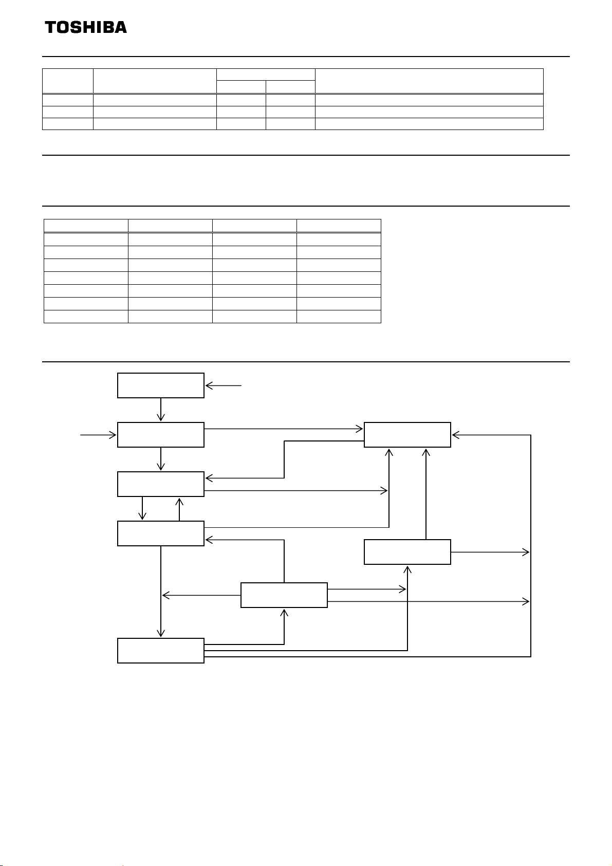
3.7.6. Control Supervisor State Transition Diagram
Non-Existant
Switch On
Reset
Initialization Complete
Main Power On
Not_Ready
Run
Startup
Main Power Off
Ready
Enabled
Switch Off
Fault Detected
Fault Reset
Stop
Complete
Stopping
Stop
Fault Detected
Main Power Off
Faulted
Fault_Stop
Complete
Fault_Stop
Fault
Detected
- 39 -
Page 41
E6581737
A
3.8. AC/DC Drive Object
Class code 0x2A. This object models the functions specific to an AC or DC Drive. e.g. speed ramp, torque
control etc.
3.8.1. AC/DC Drive Object Class Attributes
Attribute
ID
1 Revision UINT Get Revision of this object 1
2 Max instance UINT Get
Max ID of
6
class attributes
Max ID of
7
instance attributes
Name
Data
Type
UNIT Get
UNIT Get
ccess
Rules
Description
Maximum instance number of an object
currently created in this class level of
the device
The attribute ID number of the last
class attribute of the class definition
implemented in the device.
The attribute ID number of the last
instance attribute of the class definition
implemented in the device.
Default
Value
1
7
46
- 40 -
Page 42
E6581737
A
3.8.2. AC/DC Drive Object Instance Attributes
Attribute
ID
Name
Data
Type
ccess
Rules
Description
1 Number of Attributes USINT Get Number of Attributes supported
2 Attribute List
3 At Reference BOOL Get
USINT
(ARRAY)
Get List of Attributes supported
1 = Drive actual at reference (speed or
torque reference) based on mode
Requests torque or speed reference to
be local or from network.
0 = Set Reference not DN Control
4 Net Reference BOOL Get/Set
1 = Set Reference at DN Control
Note that the actual status of torque or
speed reference is reflected in atrribute
29, RefFromNet.
0 = Vendor specific mode
1 = Open loop speed (Frequency)
6 Drive Mode USINT Get
2 = Closed loop speed control
3 = Torque control
4 = Process control (e.g. PI)
5 = Position control
Actual drive speed
7 Speed Actual INT Get
(best approximation)
Units: min-1
8 Speed Reference INT Get/Set
9 Current Actual INT Get
10 Current Limit INT Get/Set
11 Torque Actual INT Get
15 Power Actual INT Get
Speed reference
Units: min-1
Actual motor phase current
Units: 100mA
Motor phase current limit
Units: 100mA
Actual torque
Units: Nm
Actual output power
Units: W/2
PowerScale
Acceleration time
18 Accel Time UINT Get/Set
Time from 0 to High Speed Limit
Units: ms/2
TimeScale
Acceleration time
19 Decel Time UINT Get/Set
20 Low Speed Limit UINT Get/Set
21 High Speed Limit UINT Get/Set
Time from 0 to High Speed Limit
Units: ms/2
TimeScale
Minimum speed limit
Units: min-1
Maximum speed limit
Units: min-1
26 Power Scale SINT Get Power scaling factor.
28 Time Scale SINT Get/Set Time scaling factor.
Status of torque/speed reference
29 Ref From Net BOOL Get
0 = Local torque/speed reference
1 = DeviceNet torque/speed reference
46 Drive on Hours DINT Get
Number of hours
Units: h
3.8.3. AC/DC Drive Object Common Services
Service
Code
Service Name
Supported
Class
Instance
Description of Service
0x0E Get_Attribute_Single Yes Yes Returns the contents of the specified attribute.
0x10 Set_Attribute_Single
N/A
Yes
Modifies the value of the specified attribute.
3.8.4. AC/DC Drive Object Specific Services
AC/DC Drive Object provides no object specific services for the slave.
Default
Value
19
-
-
-
-
-
-
-
-
-
-
-
-
-
-
0
0
-
-
- 41 -
Page 43
E6581737
A
A
3.9. Acknowledge Handler Object
Class code 0x2B. This object is used to manage the reception of message acknowledgements. This object
communicates with a message producing Application Object within a device.
3.9.1. Acknowledge Handler Object Class Attributes
Attribute
ID
1 Revision UINT Get Revision of this object 1
2 Max instance UINT Get
Name
3.9.2. Acknowledge Handler Object Instance Attributes
Attribute
ID
1 Acknowledge timer UINT Get/Set
2 Retry limit USINT Get/Set
COS producing connection
3
instance
Name
3.9.3. Acknowledge Handler Object Common Services
Service
Code
0x0E Get_Attribute_Single Yes Yes Returns the contents of the specified attribute.
0x10 Set_Attribute_Single
Service Name
3.9.4. Acknowledge Handler Object Specific Services
Acknowledge Handler Object provides no object specific services.
Data
Type
Data
Type
UINT Get
Supported
Class Instance
N/A
ccess
Rules
ccess
Rules
Yes
Description
Maximum instance number of an object
currently created in this class level of
the device
Description
Time to wait for acknowledge before
resending
Number of Ack Timeouts to wait before
informing the producing application of a
RetryLimit Reached event.
Connection Instance which contains the
path of the producing I/O application
object which will be notified of Ack
Handler events.
Description of Service
Modifies the value of the specified attribute.
Default
Value
1
Default
Value
(16)
1
(Connection
Instance ID)
- 42 -
Page 44
E6581737
3.10. Parameter Object (Vender Specific Profiles)
Class code 0x65. This object provides VF-MB1/S15’s parameter access.
Drive parameter’s Attribute ID is 3, VF-MB1/S15’s parameter is set as Instance ID.
For example, in case of set 5 sec. to "Acc. time", the minimum unit of "Acc. time" is 0.1 sec., the
set vlaue is
5 / 0.1 = 50 = 0x0032 (Hex.)
And the communication number of "Acc. time" is "0009".
So, set the value 0x0032 to Class 0x65, Instance 0009, Attribute 3 to use Set Single Attribute
service.
* Parameter au1 can not be accessed by using Class 0x65. Please, use Class 0x64.
Also, Class 0x64 at the previous model is supported. All parameter’s Attribute ID is 3.
The instance ID should be set " VF-MB1 or VF-S15 parameter communication number +
0x4000".
In the case of the parameter from which a communication number begins in "F", it should be set
"VF-MB1/S15 parameter communication number - 0x8000".
Example 1.
In case of Basic parameter “CMOd - Command mode selection”,
Communication No: 0003 -> Instance ID: 4
Example 2.
In case of Extended parameter “F268 - Updown frequency default value”,
Communication No: 0268 -> Instance ID: 4
Example 3.
In case of Monitor parameter “FE03 - Output current”,
Communication No: FE03 -> Instance ID: 7
* Monitor parameter can access "Get" only.
003
268
E03
Notice
These procedure writes in EEPROM.
Do not write the same parameter to the EEPROM more than 10,000 times.
The life time of EEPROM is approximately 10,000 times.
- 43 -
Page 45
E6581737
4. DeviceNet Local/Remote Operation
The example below shows how to configure the VF-MB1/S15 for local / remote operation.
<Terminal function>
F terminal ............ RUN command
R terminal............ DeviceNet /Local (Terminal in this example) switching
VIB terminal......... Operation frequency command
<Wiring>
<Parameter setting>
cmod (command mode selection) = 0 (terminal board)
fmod (frequency setting mode selection 1) = 2 (VIB)
f112 (input terminal selection 2 (R)) = 48 (DeviceNet/Local control)
<Operation>
R-CC terminal open:
R-CC terminal closed:
Variable resistor for adjustment
10k ohm
Operation command
DeviceNet /Local
Switch
VF-MB1 is controlled as slave device of DeviceNet.
F-CC terminal short to RUN
F-CC terminal open to STOP
Output frequency is set up by the VIB signal input.
VF-MB1/S15
PP
VIB
CC
F
SOURCE
R
P24
OUT
SW1
SINK
5. EDS file
Even if access to each parameter of VF-MB1 or VF-S15 uses a configuration tool and an EDS
file, it is possible. As for acquisition of an EDS file, please contact your Toshiba distributor.
Please use what was in agreement with the software version of usage's VF-MB1 or VF-S15.
- 44 -
- 44E -
 Loading...