

)
A
p
Density (Consistency) Meter LQ500
Introduction
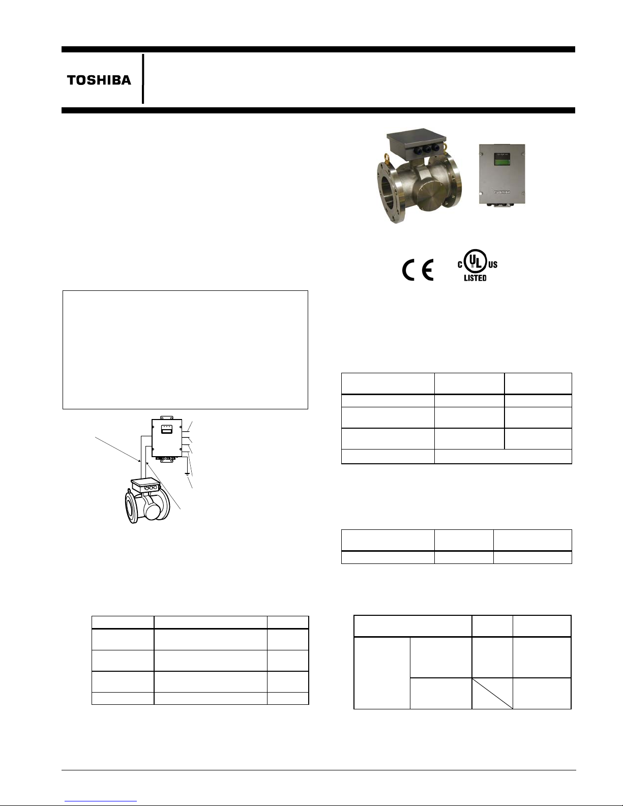
The LQ500 density (consistency) meter uses
microwave phase shift technology to determine
concentrations of solids in the material to be measured
flowing through pipes. It can perform a stable and
realtime density (consistency) measurement because
this technology is not affected by flow velocity along
with fluid color, and also is not easily affected by
contaminants and low process pressure rate. As the
LQ500 has no moving parts, it is reliable and virtually
maintenance free.
Since the output of the LQ500 is theoretically linear, it
can be applied to a wide range of density (consistency)
measurement.
<Notice>
The LQ500 requires a full pipe to measure the
density (consistency). Contact Toshiba before
installation in the following cases:
<Possibility of unfilled condition>
(a) When it is installed at the discharge of a pump.
(b) When installation is horizontal, and unfilled
condition occurs inside the pipe.
(c) A process where the pipe becomes unfilled
when the operation is stopped.
Cable for power supply
(Detector/converter)
Figure
■
Standard Configuration
• Density (Consistency) Meter: 1 set
(Detector and converter separate mounted)
• Accessories: 1 set (see Table 1 below)
Communication
Note 1: Need to prepare a power supply cable for the
External Sync control
contact in
DI / DO
Density (consistency
measurement output 4-20mA
C power supply
Ground resistance
100 ohm or less
Cable for communication
(Detector/converter)
1. LQ500 Configuration Diagram
ut
Table 1. Standard Accessories
Items Specifications Quantity
Power supply
cable
cable
Fuse
Document Instruction manual 1
LQ500.
Refer to the section of cable specifications at the
overall specifications in detail.
Between detector and
converter (*1)
Between detector and
converter (*1)
2A(T), 250 V
(glass tube, 5.2 dia. x 20 mm)
10 m
(32.8 ft)
10 m
(32.8 ft)
2
Figure 2. LQ500 Density (consistency) Meter
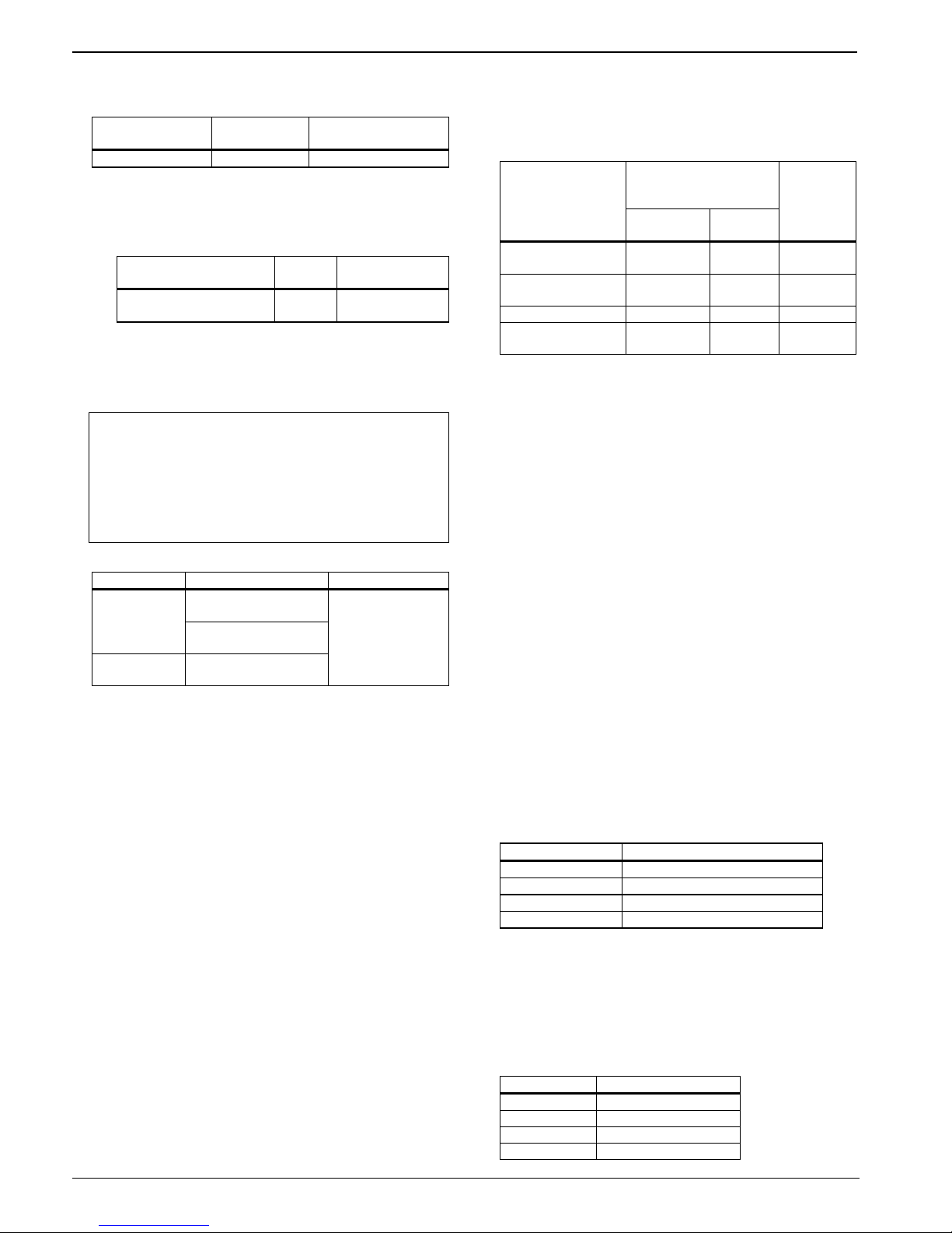
Specifications
■
Overall Specifications
Measurement method:
Microwave
Measurement
Meter size 50 mm (2”)
Span (*2) 2 to 50 %TS (*1) 1 to 50%TS (*1)
Lower limit setting
range (4 mA)
Upper limit setting
range (20 mA)
Setting increments 0.1%TS
Repeatability:
Meter size 50 mm (2”)
Repeatability ±0.02%TS ±0.01%TS
Note 1 : Above values are the results of commuting ability
Note 2 : Density (consistency) determination
Density
(consistency)
determination
repeatability
*The characteristics of sample reagent has errors due
to sample tests such as uneven density (consistency)
distribution.
*Full scale is the maximum value in the measurement
phase difference method
range:
0 to 48%TS 0 to 49%TS
2 to 50%TS 1 to 50%TS
*1 TS: Total Solids
*2 Span = Upper range – Lower range
*3 The material to be measured must be fluid
and be filled evenly with no voids.
80 to 300 mm
in the phase measurements of the converter.
repeatability for sample reagent;
Meter size
For the full
scale value of
2%TS or
greater
For the full
scale value of
less than 2%TS
50 mm
(2”)
±2%FS ±2%FS
±4%FS
80 to 300 mm
(3” to 12”)
(3” to 12”)
80 to 300 mm
(3” to 12”)
No. EJL- 106A
LQ500
range, which is the upper limit setting range.
Resolution:
(2”)
80 mm (3”)to
300 mm (12”)
80 mm (3”)to
300 mm (12”)
Meter size 50 mm (2”)
Resolution 0.002%TS 0.001%TS
Note 1: Above values are the results of commuting
ability in the phase measurements of the
converter.
Note 2: Density (consistency) determination
resolution for sample reagent;
Meter size
Density(consistency)
determination repeatability
50 mm
0.1%TS 0.05%TS
* The density (consistency) determination resolution
stated above is defined due to manufacturing
limitation to make reagents with stable distribution
and a minimum difference of fluid density
(consistency).
<Notice>
1. Install a sample tap near the LQ500 as close
as possible to get an accurate density
(consistency) measurement using the LQ500.
2. Take several samples in rapid sequence for
more accurate density (consistency)
measurement with less human error factors.
Environmental conditions:
Items Temperature range Humidity range
Standard: 0 to 50 deg.C
Detector
Converter
(32 to 122 deg.F)
Option: -20 to 50 deg.C
(4 to 122 deg.F) (*1)
0 to 50 deg.C
( 32 to 122 deg.F)
5 to 85%RH
(no condensation)
*1 A rubber heater is installed at the RF part of the
detector.
Need to prepare an additional power supply either
100Vac type or 200Vac type for it by yourself.
Determine one of them at the specification code.
This option is available for detector only.
Structure: Converter;IP65,
Detector:IP67, Watertight
Note: Outdoor installation is possible. However,
provide a sunshade for the converter section if
direct sunlight is unavoidable.
Microwave power: 10 mW
Vibration resistance:
No resonance to the following levels of
vibration:
(1) No failure for 5 to 150 Hz with the following
acceleration in each device for 30 minutes in
each axis of X, Y, and Z (90 minutes);
Converter: 4.9 m/s
2
, Detector: 25m/s2
(2) No failure for 5 to 150Hz with the following
acceleration in each device for 3 minutes in
each axis of X, Y, and Z, 10 times (90
minutes as total);
Converter: 4.9 m/s
2
, Detector: 25m/s2
Note: Avoid using the LQ500 in an environment with
constant vibration.
Cables: See the Table 2
Table 2. Cable specifications
Cables Between detector
(RF part)and converter
Specifications
Power supply
Cable type
Cross-sectional
area (*3)
Number of cores 2 5 3
Cable diameter (*4)
CVVS-2C-2S
(*1)
Communi-
(24Vdc)
2 mm
11 to 13
2
mm
cation
CVVS-5C-
1.25S
2
1.25 mm2 2 mm2
11 to 13
mm2
*1 10m (32.8 ft) length is packed as standard.
*2 Need to prepare this cable by the customer.
*3 Need to use a sheathed cable.
*4 If the diameter of the cable is smaller than the inside
diameter of the packing, enlarge the cable diameter to
the same size as the packing by wrapping around the
cable.
This dimension is coming from a diameter of the
cable gland of the LQ500.
Power
supply
cable of
LQ500 (*2)
CVV-3C-2S
11 to 13
mm2
Conformance to European Community Directives:
• EMC directive 89/336/EEC
• The low voltage 93/68/EEC
• PED 97/23/EC (Note l)
Note: See table 6 in detail.
Approved hazardous locations certification:
UL/CUL Class I, Division 2, Groups A, B, C and
D (UL/CULonly for explosion proof)
Weight: Refer to Outline Dimensions (Table 3).
Part 15 of the FCC rules: Certified.
■
Detector Specifications
Meter size: 50mm (2”), 80mm (3”), 100mm (4”),
150mm (6”), 200mm (8”), 250mm
(10”), and 300mm (12”)
Flange standard and maximum working pressure:
Flange standard Maximum working pressure
ANSI Class 150 1 MPa (150 psi)
DIN10 and BS10 1 MPa (10 bar)
DIN 16 1.6 MPa (16 bar)
JIS 10K 1 MPa (10 kgf/cm2)
Note: Each product was passed a hydraulic test under
twice pressure rate for 15 minutes toward the
specification.
Fluid temperature:
0 to 100 deg.C (32 to 212 deg.F) without freezing
and bubbles conditions
Allowable fluid conductivity:
Meter size Fluid conductivity
50 mm (2”) 20 mS/cm maximum
80 mm (3”) 16 mS/cm maximum
100 mm (4”) 15 mS/cm maximum
150 mm (6”) 10 mS/cm maximum
2
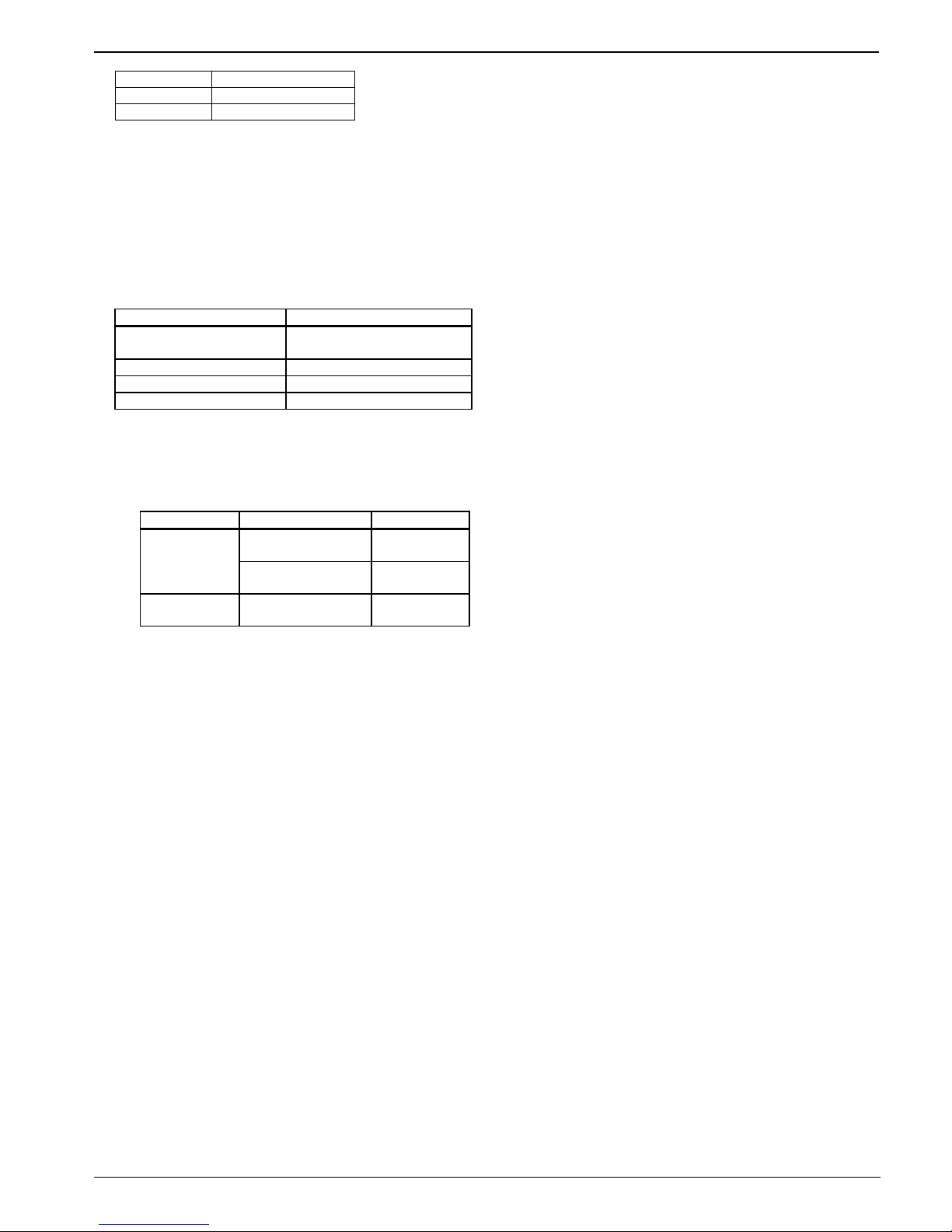
LQ500
200 mm (8”) 8 mS/cm maximum
250 mm (10”) 8 mS/cm maximum
300 mm (12”) 6 mS/cm maximum
Note 1: The LQ500 can not have an accurate density
(consistency) measurement when it is over the
specification according to reduce the microwave signal.
Note 2: The LQ500 density (consistency) measurement
for application where liquids containing highly
conductive particles such as active carbon and
metal particles may be affected. Consult
Toshiba for detail when the measuring liquid
contains such particles.
Wetting materials:
Name Materials (*1)
Main pipe
Temperature detector sheath 316 stainless steel (*4)
Applicator window Polysulfone (*4)
Applicator window sealant Fluoric rubber
*1 Avoid using the LQ500 for applications where
harmful liquids that cause corrosion, deterioration, or
changes in quantity for the wetting materials are used.
Make sure all materials at these wetting parts that are
suitable for your CIP or not before cleaning.
*2 The smoothness inside the pipe on this material is;
Type Meter size Smoothness
Standard type
Option type
*3 State the wetted materials when you choose these
options.
*4 The materials of them are changed for abrasive
applications.
Need to choose the specification code for this
application.
SCS14A cast (equivalent to
316 SS) (standard) (*2, *3)
50 to 200 mm
(1/2” to 8”)
250 & 300 mm
(10” & 12”)
50 to 300 mm
(1/2” to 12”)
No buffing
Buffing # 150
Buffing # 150
Applicator:
Serves as an antenna to send
and receive
microwave signals, one set provided.
Temperature detector: RTD (Pt100)
Fitting:
Direct fitting to vertical or horizontal
piping. (Refer to the section of Piping
Precautions.)
■
Converter Specifications
Output signals
• Density (consistency) measurement output:
4-20mAdc (load resistance 750 ohm maximum,
isolated output.)
• Density (consistency) fault or Maintenance
signal: 125Vac, 0.1A (resistive load) solid
state contact; opens when an error occurs in the
converter or when the LQ500 is in the setting
change mode, otherwise the contact remains
closed.
Communication signal:
Digital signal is superimposed on 4-20mAdc
current signal (conforming to HART protocol(*1)).
Load resistance:240 to 750 ohm
Load capacity:0.25μF maximum
*1 HART (Highway Addressable Remote
Transducer) protocol is a communications
protocol for industrial sensors recommended
by HCF (HART Communication Foundation).
Note: The optional AF900 hand-held terminal can be
used to operate the LQ500 from remote places
by connecting the AF900’s probe lead between
the LQ500’s 4-20 mA dc output signal lines.
Input signals
• External synchronized input signal:
In order to avoid problems of density
(consistency) measurement such as
inhomogeneous condition caused by
discontinuous process operation and empty pipe
condition caused by stopping process operation.
<Specification>
One dry “make” contact;
Contact capacity of 24Vdc with 0.1 to 2.0A is
required.
This contact signal can be used to start or stop
density (consistency) measurement in
synchronization with an external contact, such
as the contacts on a pump.
The measurement starts or stops as follows:
Contact closed: Starts density (consistency)
measurement.
Contact open: Stops density (consistency)
measurement.
• Density multiplier switching signal:
In order to achieve selecting up to 4 kinds of
liquid concentration measurement independently
as maximum.
<Specification>
Two voltage signals described below are required:
Input voltage: H level: 20 to 30 Vdc
L level: 2 Vdc or less
Input resistance: Approx. 3k ohm
• Conductivity correction signal:
Need to prepare an additional conductivity meter
when using this function. Install in where is able
to have a stable and accurate measurement.
<Specification>
Input signal: 4 to 20mAdc
Conductivity range: 0 to 10mS/cm
Update period for density (consistency)
measurement output and display:
Approx. 1 second
Functions by software as standard:
• Data saving function:
In order to save measurement data into the
memory of converter temporary.
The oldest data is overwritten.
<Specification>
Data storage points: 256 points maximum.
Period: 1 to 1,800 minutes (1 minute each).
ex 1: The data is saved for approx. latest 4.26
hours when programming every minute.
ex 2: The data is saved for approx. latest 21.3
3

LQ500
hours when programming every 5
minutes.
• Moving average function:
In order to keep the average density (consistency)
output, or in order to suppress the deflection
width of the output. It helps for density
(consistency) control.
<Specification>
Enable to determine a number from 1 to 99.
• Change-rate limit function:
In order to reject the transient density
(consistency) output as noises, or a sudden
variation in the output according to intrusion by
bubbles, etc....
<Specification>
Allowable rate of change limit: 0.00 to 9.99%TS
Enable to determine a number from 0 to 99.
• Additive correction function:
Available for up to 10 kinds of mixed / blended
liquids. Sensitivity compensation can be set using
registered parameters depending on the type and
the mixing rate of liquids.
• Password function:
This function is used to limit access to changing
parameters that affect measured data by means of
a password.
Arrestor:
Arrestors are installed in the LQ500 current
output (4-20mAdc) and AC power lines.
Operation panel and Display:
Used to check data or change various settings.
Operation switches: 5 switches.
Display: 4-line, 20-character LCD (dot-matrix)
with backlight.
Power supply:
100 to 240Vac 50/60Hz (Allowable voltage: 85 to
264Vac)
Note: An additional power supply is required when
choosing an optional environmental
temperature specification type (-20 to 50 deg.C).
Refer to the section of Environmental
conditions in detail.
Note2: UL/CUL Hazardous locations type does not
have a power switch. Please prepare a power
switch outside. (Rated 250V AC,10A above,
DPST: Double-Pole/Single-Throw)
Use the power switch for Hazardous
locations in Hazardous locations area.
Power consumption: Approx. 25VA (100Vac),
Approx. 35VA (240Vac)
Housing material: Steel plate
Coating: Polyurethane
MTBF: 135.8 months under 25 deg. C (77 deg. F)
based on MLL-HDBK-217F
Installation
■
Outline Dimensions
100 (3.9”)
(H)
(X) (L)
Figure 3. LQ500 detector outline dimensions
Table 3. LQ500 detector outline dimensions
Size (mm) X (mm) H (mm) L (mm)
50 (2”) 170 (6.7”) 225 (8.9”) 300 (11.8”) Approx.22 Approx.21 (46 lb) Approx. 21
80 (3”) 200 (7.9”) 225 (8.9”) 300 (11.8”) Approx.30 Approx31 (68 lb) Approx. 26
100 (4”) 220 (8.7”) 240 (9.4”) 300 (11.8”) Approx.31 Approx.34 (75 lb) Approx. 29
150 (6”) 270 (10.6”) 260 (10.2”) 300 (11.8”) Approx.43 Approx.44 (97 lb) Approx. 42
200 (8”) 320 (12.6”) 290 (11.4”) 300 (11.8”) Approx.52 Approx.54 (119 lb) Approx. 48
250 (10”) 300 (11.8”) 315 (12.4”) 350 (13.8”) Approx.68 Approx.68 (150 lb) Approx. 64
300 (12”) 360 (14.2”) 340 (13.4”) 350 (13.8”) Approx.85 Approx.99 (218 lb) Approx. 76
DIN 16 ANSI 150 JIS 10K
190 (7.5”)250 (9.8”)
Weight (kg)
Unit: mm
4

LQ500
p
A
p
Contact signal I/O port (2)
74 (2.9”)
234 (9.2”)
communication port
Converter power
supply cable port
Reserved
(25)
(1.0”)
(15)
320 (12.6”)
45
15
(1.8”)
Converter
(0.6”)
360 (14.2”)
(0.6”)
390 (15.4”)
Contact signal I/O port (1)
Figure 4. LQ500 Converter outline dimensions
■
Installation Precautions
(1) Install the LQ500 in an environment free from
vibration and corrosive gases and in a place
which allows easy on-site maintenance.
(2) Provide a clearance space both detector and
converter to the front, rear, and above the unit.
See Figure 5.
(3) Provide a sunshade for the detector and
converter if direct sunlight is unavoidable
when installing outdoors.
(4) The LQ500 cannot be installed in an
environment where there is a possibility that
flammable or explosive gases may leak.
(5) The LQ500 should avoid the following
environmental installations:
• Places where condensation accumulates due
to sudden temperature changes.
• Places of low or high temperature that is out
of the specification.
• Places near equipment that produces strong
electric waves or electrolytes.
• Places where flammable or explosive gas
may be generated.
Unit: mm
Converter
Maintenance
ace
s
RF part
Maintenance
s
ace
500 (19.7”)
Back
Front
500 (19.7”)
600 (23.6”)
Detector
500 (19.7”)
600 (23.6”)
500 mm (19.7”) maintenance
space is also needed above unit.
Figure 5. Clearance space
Unit: mm
Weight: 7kg(15 lb)
110
(4.3”)
(119)
(4.7”)
Density signal output port
Grounding terminal
■
Piping Precautions
(1) A vertical installation of the LQ500 is
recommended.
Avoid installing horizontally (install LQ500
vertically) in case of follow ing e nvir onmen ts.
(2) Install the LQ500 in a pipeline where the
pipe is always filled with fluid and without
bubbles or entrapped air. If these conditions
are not satisfied, the measured value varies
or may give an inaccurate reading. It is
recommended that the LQ500 is installed at
the outlet instead of the suction side.
(3) Avoid places where sediment collects at the
bottom of the pipe.
(4) Avoid places where air gets into the fluid. To
avoid this problem, install the LQ500 to the
outlet of a pump, not to the suction side.
(5) When installing the detector horizontally,
install it so that the RF-part of it is oriented up
(that is, a pair of applicators stay horizontally)
600 (23.6”)
to make it easier for maintenance work and to
obtain its specified performance.
(6) The LQ500 can be installed in either direction
(upstream or downstream) and without
requiring a straight pipe section. Install it in a
place allowing easy on-site maintenance.
In the case of Wall mounting
360 (14.2”)
74 (2.9”)
In the case of 50A (2”) mounting
Steel pipe U bolt
(M10)
360 (14.2”)
Steel pipe
(50A) (2”)
a) Places where bubbles or environments
air remain in the pipe.
b) Places where solids concentration in
the fluid is not even because solids in
the fluid stay either at the bottom or
top of the pipe due to slow fluid
velocity or other reason.
c) Pipe size is enlarged to install a larger
meter sized LQ500.
5

LQ500
V
(7) Install an adjustable piping mechanism if there
is a possibility that the detector pipe may not fit
between mating flanges.
(8) Install the LQ500 in a place where enough
water pressure is applied. Therefore, it is
recommended that the LQ500 be installed as
far away as possible from the pipe outlet
opened to atmosphere. This is to prevent the
effects of air being trapped in the liquid.
(9) If there is a possibility of no liquid flow or
uneven liquid distribution occurring when a
pump is off, use an external synch control
signal to operate the LQ500 only when the
pump is working.
(10) Provide a stop valve at upstream and
downstream of the detector, and between stop
valves and the LQ500 provide the four valves
described below with a stop valve attached to
each: 1) sampling outlet valve; 2) zero point
water inlet valve; 3) vent valve; and 4) drain
valve. If it is not possible to stop the fluid at the
point where the LQ500 is installed, provide a
bypass pipe with a stop valve provided in the
middle. These valves are needed to drain the
fluid from the detector
pipe and fill it with
drinking water (density or consistency 0%) to
adjust the zero point. See Figures 6 and 7.
(11) Use gaskets for piping of the size conformed to
flange rating and of the material appropriate
for the liquid to be measured.
Install this valve to the side of the pipe in the
case of horizontal installation. It is
recommended that a 1-inch ball valve be
installed to the side of the pipe.
Stop
valve
Bypass
pipe
Stop valve
ent valve
Zero point water pipe
LQ500
Stop valve
Flow direction
(from down to up directions)
Zero point water valve
Drain valve
Drain pipe
Figure 6. Recommended Installation
(vertical installation)
Stop valve
Vent v a lve
LQ500
Sampling
valve
Zero point
water valve
Stop valve
Drain
valve
NOTE:
• Zero point water valve:
Used to supply drinking water (density or
consistency 0%) to the detector pipe for zero
point adjustment. Install this valve at the top of
the pipe in the case of horizontal installation. It
is recommended that a 1-inch ball valve be
installed on the top of the pipe and zero point
water supplied through this inlet using a vinyl
hose etc.
Note: If valve water pipe is connected to this
valve, air cannot be extracted. Therefore,
another valve (vent valve) is needed to
extract air.
• Vent valve:
Used to vent process fluids to open air when
performing zero adjustment. This helps the
drinking water (density or consistency 0%)
enter the detector pipe easily. Install this valve
on the top of the pipe in the case of horizontal
installation.
• Drain valve:
Used to drain the fluids before supplying
drinking water (density or consistency 0%) to
the detector pipe for zero adjustment. Install
this valve at the lowest point of the pipe. It is
recommended that a 1-inch ball valve be
installed at the lowest point of the pipe.
• Sampling valve:
Used to extract fluids for manual analysis.
Stop valve
Bypass pipe
Figure 7. Recommended Installation
(horizontal installation)
■
Wiring Precautions
(1) Provide a switch and a fuse to isolate the unit
from the mains power for ease of maintenance.
(2) Ground the LQ500 with 100 ohm or less
ground resistance. Do not use a common
ground shared by other power equipment.
(3) Use the accessorious cables for communication
and power supply between detector and
converter. Connect cables to the terminals that
match the marking on the cables.
(4) Use a sheathed cable with 2mm
2
cross-sectional area for AC power cable.
(5) The cables should be free from vibration and
should have no slack in the cables.
(6) Wire the LQ500 output in conduit separated
from those of AC power cable, control signals,
alarm signal or other cables which could
become the source of noise.
(7) Use a 2-wire shielded sheathed cable to wire
the LQ500 output (4-20mAdc) and
conductivity signal. Ground the shielded cable
on the receiving instrument side for both cable.
6

LQ500
pply
Tx+
TX-
Rx+
Rx-
SG
FG
+24V
0V
FG
Converter
L1
L2
AO+
AO-
DI3
DI2
COM2
DO1
COM1
DI
COM
FG
CVV
CVVS
Power su
Ground terminal (PE)
(Ground resistance 100 ohm or less)
Density (consistency) measurement output
(4-20mAdc, 750 ohm max., isolated output)
Density multiplier switching voltage inputs
(H level: 20 to 30 Vdc, L level: 2 Vdc or less and Input
resistance: Approx. 3k ohm)
Density (consistency) measurement output
(4-20mAdc, 750 ohm max., isolated output)
External synch. Control contact signal input
(Contact capacity: 24Vdc, 0.1 to 1A)
CVV
Chassis ground terminal
(Ground resistance 100 ohm or less)
100 to 240 Vac, 50/60Hz
Ground terminal
(Ground resistance 100 ohm or less)
RF part
Notice 1: Do not connect to the “FG” terminals neither communication cable nor power supply cable in the detector side.
Notice 2: Either “PE” terminal on the terminal block in the converter on the chassis ground terminal of the unit should be grounded with 100
Notice 3: Ground the shielded cable on the receiving instrument side.
Notice4: UL/CUL Hazardous locations type does not have a power switch. Please prepare a power switch outside. (Rated 250V AC,10A above,
Ec+
Ec-
FG
Tx+
Tx-
Rx+
Rx-
SG
FG
+24V
0V
FG
ohm or less ground.
DPST: Double-Pole/Single-Throw)
Use the power switch for Hazardous locations in Hazardous locations area.
CVVS
Conductivity
signal input
(4-20mAdc)
CVVS
Communication cable
CVVS
Power supply cable
Figure 8. External connections
(8) As the cable port is made air-tight using a
packing, tighten the cable gland securely when
all the wiring is completed. If the diameter of
the cable is smaller than the inside diameter of
the packing, enlarge the cable diameter to the
same size as the packing by wrapping valves
around the cable Its suitable diameter is 11mm.
Tighten the terminal screws securely. Its
suitable torque is 1.0 to 1.7 N⋅m.
(9) Screws at the terminals are needed to tighten
with 1.2 N·m torque (1.4 N·m is maximum).
(10) Do not turn on the power supply under the
uninstalled condition.
(11) Each cable in the communication cable and
power supply cable between detector and
converter has a banded marks for each
terminals. Connect them correctly without any
mismatches.
•Wiring when communications function is used
By connecting the cable lead of the optional
AF900 hand-held terminal to the density
(consistency) measurement output, you can
operate the LQ500 from remote places.
1) Make sure the load resistance of 4-20mAdc
line of output is between 240 and 750 ohm,
and the load capacitance is 0.25µF maximum.
2) The AF900’s cable lead can be connected to
the LQ500 anywhere along the current output
line. For example, the cable lead may be
connected to the signal terminals on the
receiving side in the control room. See Figure
9.
LQ500 converter
Density meter output
Hand-held terminal
AF900 (option)
Control room
Instrument (load)
Figure 9. Wiring for communication function
7

LQ500
Ordering Information
When ordering the LQ500, refer to Table 4. Type
Specification Code. An entry must be made for each of
the columns.
The following items must also be specified:
1. Fluid characteristics:
• Type of material to be measured
• Density (consistency) (max., normal, min.)
• Temperature (max., normal, min.)
• Pressure (max., normal, min.)
• Conductivity (max., normal)
2. Measurement range
3. Tag number (specify “None” if not needed)
4. Hand-held terminal Required or not
(Refer to Table 5 below.)
5.Other specific items
No. EJL-106A

LQ500
ead re
oduc
.
Table 4. Type Specification Code
(LQ500 Density (consistency) Meter)
TYPE CAT Code SPECIFICATION
1 2 3 4 5 6 7 8 9
L Q 5 0 0 Microwave Density (Consistency) Meter
A Standard
Meter Size
0 5 50mm (2")
0 8 80mm (3")
1 0 100mm (4")
1 5 150mm (6")
2 0 200mm (8")
2 5 250mm (10")
3 0 300mm (12")
Mounting Style
B JIS 10K flange connection
C ANSI 150 flange connection
F DIN 16 flange connection
Purpose
A Standard
B for PED (150 to 300 mm
C for UL/CUL Hazardous locations
Wetting parts
A SCS14A cast (Equivalent to 316L
B SCS14A cast (Equivalent to 316L
C SCS14A cast (Equivalent to 316L
D Hastelloy C pipe
Cable length between detector
A 10 m (32.8 ft) (standard)
B 20 m (65.6 ft)
C 30 m (98.4 ft)
D 40 m (131.2 ft)
E 50 m (164 ft)
X None (Note 3)
Optional specifications
None (standard) (blank codes are
A B Pipe buffing type
A C -20 to 50 deg.C (-4 to 122 deg.F)
A D Pipe buffing type with -20 to 50
A E -20 to 50 deg.C (-4 to 122 deg.F)
A F Pipe buffing type with -20 to
Note 1: The specification of PED (Pressure Equipment
Directive) is required from 150 to 300 mm (6" to
12") when the installation location is in the Europe.
Note 2: The differences between standard type are RTD
sensor and Applicator window.
Note 3: Toshiba recommends to using our specified cable.
ISO9001 and ISO14001 are certified.
Misuse of this product can result in damages to property or human injury.
R
10 11 12 13 14
(6" to 12") for EU) (Note 1)
type
SS) pipe (standard)
SS) pipe with teflon PFA coating for
sticky application
SS) pipe for abrasive application
(Note 2)
(RF part) & converter
required.)
environment temperature
specification, 200 to 240 Vac power
supply type of LQ500
deg.C (-4 to 122 deg.F) environment
temperature specification, 200 to 240
Vac power supply type of LQ500
environment temperature
specification, 100 to 120 Vac power
supply type of LQ500
50deg.C (-4 to 122deg.F)
environment temperature
specification, 100 to 120 Vac power
supply type of LQ500
lated manuals carefully before using this pr
t
Table 5. Type Specification Code
(AF900 Hand-held Terminal)
Model Specification Code
12345 6 7 8 9 10 11 12
AF 9 0 0 Hand-held terminal
L Q 3 For use with LQ series
A Display language English
A A 3 Standard
Description
Table 6. PED matrix
Flange
mm 50 80 100 150 200 250 300
inch 2 3 4 6 8 10 12
DIN16 SEP Certified
DIN10 SEP Certified
ANSI150 SEP Certified
SEP: Not required the PED.
Certified: The PED is certified.
Check your flange type and its meter size of the LQ500
whether it corresponds to the PED or not when its
installing location is in the Europe.
If yes, you need to choose the code “B” at the 10th
column in the specification code (Table 4)
Meter Size
Specifications are subject to change without notice.
Printed in Japan 2006-11 (TDOC)
© TOSHIBA Corporation 2003
All Rights Reserved.
9
 Loading...