

Page 1
6F9G0154
INSTRUCTION MANUAL
HIGH-VOLTAGE
VACUUM CONTACTORS
CAPACITOR APPLICATION
TYPE:CV-10HB 12(13.8)kV-400A-5kA
TYPE:CV-10HBL 12(13.8)kV-400A-5kA
TOSHIBA CORPORATION
© TOSHIBA Corporation 2001-2009
All Rights Reserved.
Buy: www.ValinOnline.com | Phone 844-385-3099 | Email: CustomerService@valin.com
Page 2

- 2 -
6F9G0154
CONTENTS
1.GENERAL DESCRIPTION・・・・・・・・・・・・・・・・・・・・ 2
2.PRECAUTIONS IN SPECIAL APPLICATION・・・・・ 3
3.RECEIVING AND UNPACKING・・・・・・・・・・・・・・・・ 4
4.STORAGE AND HANDLING・・・・・・・・・・・・・・・・・・・ 4
5.INSTALLATION・・・・・・・・・・・・・・・・・・・・・・・・・・・ 5
6.RATING・・・・・・・・・・・・・・・・・・・・・・・・・・・・・・・・・ 6
7.OUTLINE DRAWING・・・・・・・・・・・・・・・・・・・・・・・・ 7
8.STRUCTURE・・・・・・・・・・・・・・・・・・・・・・・・・・・・・・ 8
9.OPERATION・・・・・・・・・・・・・・・・・・・・・・・・・・・・・・ 9
10.TRIAL OPERATION・・・・・・・・・・・・・・・・・・・・・・・・13
11.INSPECTION AND MAINTENANCE・・・・・・・・・・・・・14
12.CRITERIA FOR DURABILITY・・・・・・・・・・・・・・・・18
Buy: www.ValinOnline.com | Phone 844-385-3099 | Email: CustomerService@valin.com
Page 3
- 3 -
6F9G0154
Read this manual carefully to fully understand the operation.
And keep for maintenance.
WARNING : Never remodel or disassemble the equipment nor mount
nonstandard components.
This equipment shall only be used inside a metal enclosure (grounded)
in other establishments than domestic , or those that are connected to
the public power source system.
1. GENERAL DESCRIPTION
(1) Ambient condition
The type CV vacuum contactor is manufactured in accordance with IEC 60470(2000).
The vacuum contactor should be used in the following conditions.
Table 1
Normal service condition
-Altitude : Less than 1000m
-Ambient temperature : -5℃ min. to +40℃ max.
Its average over a period of 24h
does not exceed +35℃
-Relative humidity : 45% min. to 85% max.
-Vibbration : 20Hz -9.8m/s
2
or less
CAUTION : Do not use in condition other than those specified
above , please consult .
(2) Locative condition
The location where the contactor is to be installed should be free from dust.
Corrosive gas and moisture.
When it is be used in a chemical plant or in outdoor panels,
take necessary precautions against corrosion,
water seepage and condensation.
See page 2.
Buy: www.ValinOnline.com | Phone 844-385-3099 | Email: CustomerService@valin.com
Page 4
- 4 -
6F9G0154
2. PRECAUTIONS IN SPECIAL APPLICATION (outdoor cubicle etc.)
In application, check the follow items, please carry out the maintenance
frequently. or perform the countermeasure.
(Visual inspection: once a month, regular inspection: once a year)
Table 2 Precaution in special application
Special condition Instance Caution items
Contamination
Sea breeze
Dust, iron-dust etc.
is very more place.
Place where suffer the
sea breeze.
Reduction of ventilation
Setting of ventilation for
sea breeze.
Frequent inspection.
High humidity
Place where very more
snow and ice.
More humidity.
Place where near the
cooling tower.
Place where cause changing
the temperature suddenly.
Setting the space heater.
Setting the ventilation.
Prevention of flooding
into the cable pit.
Corrosion gas
Corrosion gas which come
into the airport, chemical
Industry and water cleaning.
(EX.)
SO
2
, Cl2 ,NO2
Protection from corrosion
gas .
Anti-gas treatment.
Examination of changing
of the insulation material.
Buy: www.ValinOnline.com | Phone 844-385-3099 | Email: CustomerService@valin.com
Page 5
- 5 -
6F9G0154
3. RECEIVING AND UNPACKING
WARNING : If any parts are damaged or missing.
Do not install that has been damaged.
Make the following checks after unpacking :
(1) Check if there is any damage , foreign matter trapped , or water seepage
into the contactor.
(2) Check the nameplate to see if the specifications on the plate are correct.
(3) Check the contact wear gauge and control cable.
(4) Check the tripping rod (Latched type).
4.STORAGE AND HANDLING
When the contactor is to be stored over a long period , the storage area
should be dry and dust free area.
If the contactor is left outdoors or in adverse conditions , corrosion
from gas , rust or insulation deterioration may result.
CAUTION : In handling , do not throw or drop contactor.
The contactor may break.
Buy: www.ValinOnline.com | Phone 844-385-3099 | Email: CustomerService@valin.com
Page 6

- 6 -
6F9G0154
5.INSTALLATION
When installing , protect from dust. Particularly when the contactor
is installed while the building is under construction , shield it from
cement dust and other foreign matter.
The following precautions should be taken.
(1) The mounting surface must be horizontal (level : less than ±1mm).
When the mounting surface is not horizontal , adjust with spacers.
(2) There are four mounting holes.
Use M10 bolts to securely mount the contactor.
(3) In wiring the main circuit terminals , ground terminals and control
circuit , wires should be given sufficient length to be flexible.
The ground wires should be more than 5.5mm
2
in cross section.
(4) Do not mount the contactor with its front inclined downward.
This may result in malfunction.
(5) Do not touch the vacuum interrupter surface with soiled hands.
(6) When it is applied to a capacitor load , be sure to used a space heater
to keep humidity low.
CAUTION : Do not install on energize contactor that has been bad condition.
Buy: www.ValinOnline.com | Phone 844-385-3099 | Email: CustomerService@valin.com
Page 7
- 7 -
6F9G0154
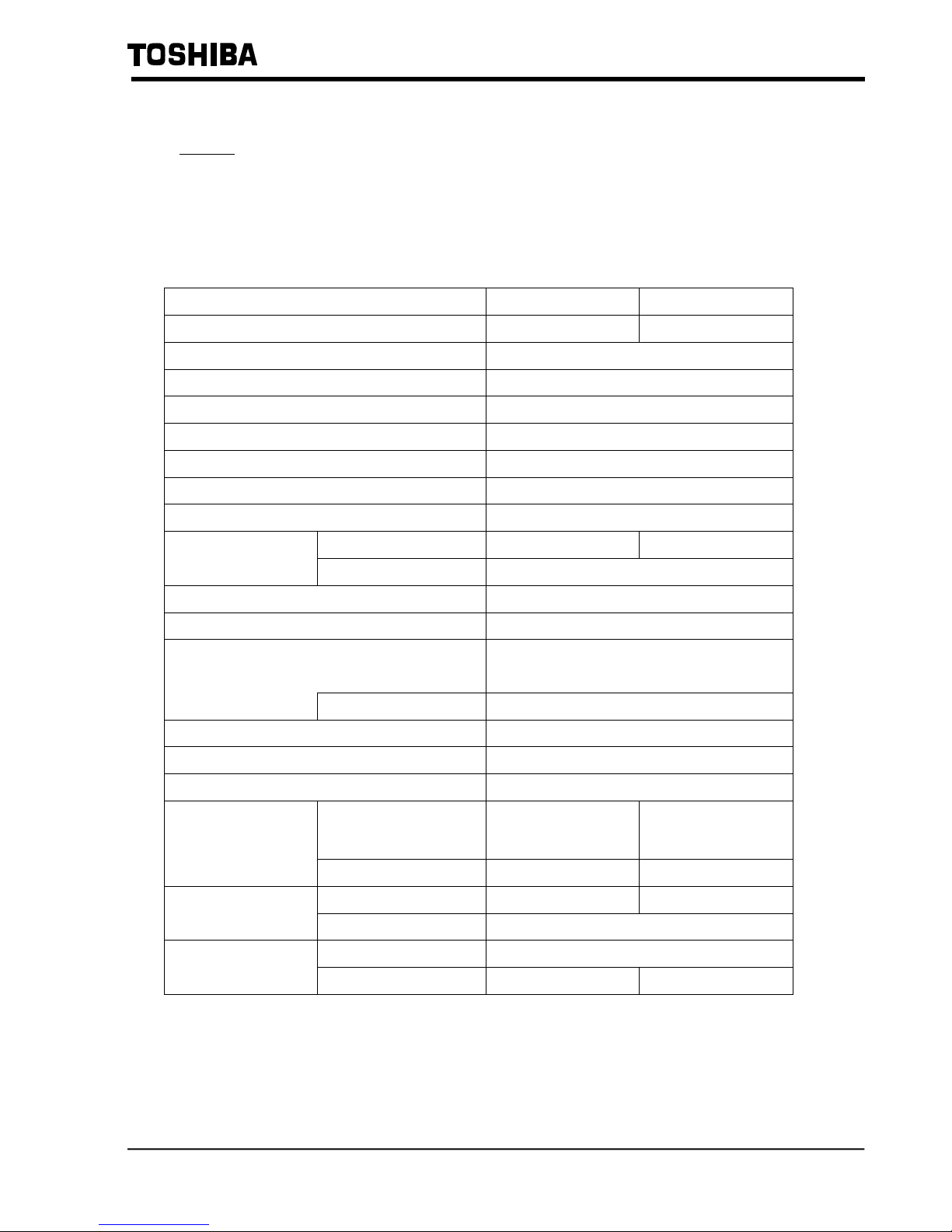
6.RATING
DANGER : Do not exceed the ratings specified on the contactor.
Table 3 Ratings
Type- form CV-10HB CV-10HBL
Operating mechanism Non-latched Latched
Rated operation voltage (kV)
12 (13.8)*
Rated insulation level (kV) AC.28 , Imp.75
Rated operational current (A) 400
Thermal current (A) 450
Rated frequency (Hz) 50/60
Rated short-time withstand current (A-s)
5000-1
Rated peak withstand current (A) 12500
Operations/hour 300 120 Rated duties
On load factor 40%
Rated making capacity (kA)
3.2(C-10s×100times)
Rated breaking capacity (kA)
2.56(CO-30s×25times)
Short-circuit making and breaking current
(kA)
5
Duties
O-3min-CO-3min-CO
Withstand overload current (kA-s)
8.0-1sec , 1.92-30sec
Mechanical operation (million) 0.25
Electrical operation (million) 0.1
Closing voltage
100-240VAC
100-220VDC
100-240VAC
100-250VDC
Rated supply voltage
(Standard)
Tripping voltage
- 100-110VDC
Contact arrangement
4NO-2NC 2NO-1NC
Auxiliary switches
Life (million) 0.1
Closing
6~7
Operating current (A)
(at 100V)
Holding/Tripping
0.6~0.7 3~4
* :13.8kV (maximum) for capacitor switching.
The rated making/breaking capacity has been confirmed at 12kV.
Buy: www.ValinOnline.com | Phone 844-385-3099 | Email: CustomerService@valin.com
Page 8

- 8 -
6F9G0154
7.OUTLINE DRAWING
COUNTER
INDICATOR
OPENING
CONTROL
METAL
MAIN
TERMINALS
INSULATION
TYPE
CV-10HB(L)
INTERRUPTERS
526
500
475
165 165
235
193
146
30
165 165
30
MOUNTING HOLES
15
15
24
137 376565
RECOMMEND
CONNECTOR
DIA.13-6HOLES
VACUUM
BARRIER
(OPTION)
DIA.4-14
DIA.20-2
LIFTING
HOLES
PARTITION
DISTANCE
COVER
FOR
MANUAL
TRIP
(LATCHED TYPE)
(HORIZONTAL MAIN TERMINALS)
Fig.1 OUTLINE DRAWING(mm)
200
474
565
110
320
6
206
6
Buy: www.ValinOnline.com | Phone 844-385-3099 | Email: CustomerService@valin.com
Page 9

- 9 -
6F9G0154
8.STRUCTURE
Buy: www.ValinOnline.com | Phone 844-385-3099 | Email: CustomerService@valin.com
Page 10

- 10 -
6F9G0154
9.OPERATION
The drive unit for the electromagnet is installed in the bottom frame.
Molded and wired on the printed circuit.
The closing circuit can be operated using either in AC or DC by the drive unit.
The optional latch trip circuit uses DC as standard.
When a latched contactor is operated using AC power, it is recommended that a
Capacitor trip device be used.
The standard operating voltage is as follows:
Non-latched type(normally energized) : 100-240 V AC /100-220V DC
Latched type :100-240V AC /100-250V DC closing voltage
:100-110V DC tripping voltage
1
2
SWITCHING
OSCILLATION
POWER
TIMER
VOLTAGE
DETECT
52CC
Diode
(Latched type)
Fig.3 Internal Configuration of Drive Unit
CAUTION : Do not touch the drive unit without trouble.
Buy: www.ValinOnline.com | Phone 844-385-3099 | Email: CustomerService@valin.com
Page 11

- 11 -
6F9G0154
(1) CONNECTION OF CONTROL POWER SUPPLY
Fig.4 and Fig.5 show the internal connections of the normally energized type
latched type respectively.
According to there figures, connection should be made of the control power
supply and open / close command contact (power relay contact).
Du
5
1
6
2
T1 T5 T6 T7 T10
T11 T15 T16 T17 T19T18
1~6
CONTACTOR TERMINAL NUMBERS
記 号
名 称
52CC
Du
AUS
CLOSING COIL OF CONTACTOR
DRIVE UNIT
AUXILIARY SWITCH
123456789
10
20191817161514131211
T7T5
T6
T17T15
T16
AC/DC
AC/DC
T1
T11
10
11
12 8
97
654
31
AUS
2
52CC
T8
T8T9T10
T18
T19
T20
CONTROL CONNECTOR
T9
T20
Fig.4 Internal connection of the normally energized type.
Du
5
1
6
2
T1 T5 T6 T7 T3
T11 T15 T16 T17 T13T18
1~6
CONTACTOR TERMINAL NUMBERS
記 号
名 称
52CC
Du
AUS
CLOSING COIL OF CONTACTOR
DRIVE UNIT
AUXILIARY SWITCH
123456789
10
20191817161514131211
T7T5T3
T6
T17T15T13
T16
DC/AC
DC/AC
T1
T11
10
11
12 8
97
654
31
AUS
2
52CC
T8
52TC
4
52TC
D
TRIPPING COIL OF CONTACTOR
DIODE
D
T8
T18
CONTROL CONNECTOR
Fig.5 Internal connection of latched type
Buy: www.ValinOnline.com | Phone 844-385-3099 | Email: CustomerService@valin.com
Page 12

- 12 -
6F9G0154
(2) STANDARD OPERATION CIRCUIT
Shown below are the vacuum contactor and its auxiliary circuits (control and
monitoring).
Fig.6 represents the standard operation circuit of the normally energized type
and Fig.7 the latched type.
Wiring should be done according to these circuit diagrams.
Du
5
1
6
2
T1
T5 T6 T7 T10
T11 T15 T16 T17 T19T18
10
11
12 8
97
654
31
AUS
2
52CC
T8 T9
T20
OFF
REMOTE
SWITCH
ON
START
INTERLOCK
STOP
INTERLOCK
2E-RY
4
E
E
EE
4
4
VMC
AC100-240V
DC100-220V
COS
*1
Fig.6 Standard operation circuit of normally energized type.
NOTE:● Be sure to use quickly AC auxiliary relay contact NO for self-holding.
If the self-holding circuit is formed by using the auxiliary contact No
of the vacuum contactor , welding of the main contact may result when
the start button is pushed incompletely(refer to *1 in Fig.6).
Buy: www.ValinOnline.com | Phone 844-385-3099 | Email: CustomerService@valin.com
Page 13

- 13 -
6F9G0154
Du
5
1
6
2
T1
T5
T6 T7 T3
T11
T15
T16 T17 T13T18
10
11
12
8
97
654
31
AUS
2
52CC
T8
52TC
4
D
EE
START
INTERLOCK
4
E
OFF
4
E 2E-RY
ON
REMOTE SWITCH
VMC
DC100-220V
COS
(a) Shunt trip
Du
5
1
6
2
T1
T5
T6 T7 T3
T11
T15
T16 T17 T13T18
10
11
12
8
97
654
31
AUS
2
52CC
T8
52TC
4
D
EE
START
INTERLOCK
4
E
OFF
4
E 2E-RY
ON
REMOTE SWITCH
VMC
AC100-240V
PU
NV
CTD
COS
(b) Capacitor trip
Fig.7 Standard operation circuit of latched type.
NOTE:● Electrical trip-free circuit must be prepared outside the contactor.
● A stable DC power source such as battery is recommended for the
control circuit.
If DC power source is not available, employ a AC closing and a
Capacitor trip.
● Be sure to use the control connector between No.3 and No.13
(auxiliary contact) for trip circuit.
Connect the control connector between No.5 and No.15
(auxiliary contact) for control relay circuit.
Buy: www.ValinOnline.com | Phone 844-385-3099 | Email: CustomerService@valin.com
Page 14

- 14 -
6F9G0154
10.Trial operation
Warning : Make sure main power is OFF.
After mounting and wiring of the vacuum contactor, make the following inspections.
1) Check for any loose connections.
2) Check for any wiring errors. Perform this test with only the control circuit energized.
confirm that the operation is correct. For the latched type contactor, check that the
latch correctly engages and trips when the close/trip signals are applied. Also,
manually trip the contactor using trip lever to verify proper operation.
Buy: www.ValinOnline.com | Phone 844-385-3099 | Email: CustomerService@valin.com
Page 15

- 15 -
6F9G0154
11.INSPECTION AND MAINTENANCE
To maintain the function and performance of the vacuum contactor for a long period
of time, the following inspections and maintenance procedures are recommended.
The intervals between inspections may vary depending on the conditions of use and
the environment under which the contactor is used. The initial inspection should be
carried out within one year of the start of equipment operation, and the succeeding
check intervals should be determined according to the result of the initial inspection.
See Section 2 for use under special environment as in outdoor cubicles.
(1) Patrol Inspection(every 1-6 months)
With the cubicle energized, visually check from out side the cubicle according to
the check list of Table 4,5.
WARNING : When opening the door of the cubicle, do not come close
to danger area.
Table 4 Patrol inspection items
Check item What to check
Abnormal noise Check if corona discharges or operation
magnets are not producing noise.
Abnormal smell Check if corona discharges or overheat are
not producing abnormal smell.
Table 5 Patrol inspection items(cont.)
Check item What to check
Abnormal discoloration Is there not any discoloration due to
overheat?
Damage Is there not any crack, break or dislocation
of insulating material or operation tools?
Open/close indication Is the OPEN/CLOSE indication (lamp)
normal?
Buy: www.ValinOnline.com | Phone 844-385-3099 | Email: CustomerService@valin.com
Page 16

- 16 -
6F9G0154
(2) Periodical Inspection/Detailed Inspection(every 1-2 years or every
20,000 operations)
The facility should be removed out of service and perform inspection
According to the instruction given in Table 6.
WARNING : Contact with energized components can cause severe injury
or death.
Turn-off and lock out primary and control circuit before servicing.
Buy: www.ValinOnline.com | Phone 844-385-3099 | Email: CustomerService@valin.com
Page 17

- 17 -
6F9G0154
Table 6 Periodical inspection and detailed inspection
Location What to inspect Decision criteria What to do
Appearance
Abnormal appearance
damage
Check by sight. Replace broken
Parts.
Contactor as
a whole
Insulating
Material
Check if moisture or
dust adheres to the
insulator.
Under dusty environments,
frequent inspection
should be done.
Check by sight.
Clean.
Sliding parts
Check for wear, loose or
seized parts.
Spring
Rust, deformation,
discoloration, or damage.
Electromagnets Discoloration, rust,
wear, or loose mounting.
Latch
mechanism
Check for scores and
wear
Closing coil,
trip coil
Check for discoloration
and burned parts.
Operating
devices
Fastenings
Check for loose bolts or
nuts.
Check bye sight.
If necessary,
check correct
operation.
Also check loose
fastenings.
Clean parts and
remove foreign
matters.
Pour oil in
Adequate amount.
Primary
circuit
Terminal,
movable
conductor
Discoloration of terminal
and coupling conductor,
loose fastenings.
Check by sight.
check the
tightness.
Retighten.
If necessary,
investigate the
cause and replace
parts.
Vacuum
Contact wear
Check contact wear and
wipe.
See Table 7.
Replace vacuum
Interrupter.
Vacuum
container
Check moisture and dust
adhering to the surface.
Check by sight. Clean.
Interrupter
Vacuum level Check vacuum level by
withstand voltage test.
Apply AC17kV
for 1minutes.
If found abnormal,
inform the maker.
Buy: www.ValinOnline.com | Phone 844-385-3099 | Email: CustomerService@valin.com
Page 18

- 18 -
6F9G0154
Location What to inspect Decision criteria What to do
wiring
Check for discoloration
and tightness.
-
Retighten.
Auxiliary switch Amount of dust attached. Check by sight. Replace if damage
is excessive.
Control
equipment
Drive unit Overheat, discoloration. Check by sight. Replace if abnormal
Main circuit
Measure insulation
resistance between
phases, between
electrodes and between
circuits and ground.
(Measurement is taken
by 1000V megger.)
More than 50MΩ
Insulation
resistance
Operation
circuit
Measure insulation
resistance between
circuits and ground.
(Measurement is taken
by 500V megger.)
More than 1MΩ
When the insulation
resistance is
below the standard
level, investigate the
cause and, if
necessary, replace
parts.
Dielectric
strength
Main circuit Measure dielectric
strength between phases,
between electrodes and
between circuits and
ground.
AC 1.5E for
10 minutes.
If found abnormal
inform the maker.
Open/close operation Perform open/close
operation by electric
operation test to confirm
the correct operation.
If found abnormal,
check and repair.
If necessary,
replace faulty parts.
Remarks: For extraordinary (unscheduled) inspections , pick up check items from the above
table.
Buy: www.ValinOnline.com | Phone 844-385-3099 | Email: CustomerService@valin.com
Page 19

- 19 -
6F9G0154
Table 7 Gap/wipe standard value
(mm)
Parts name Gap Wipe Allowable wear
Normally
energized
type
7.0~7.5
More than 3.0 2.0
Vacuum
interrupter
Latch type
7.0~7.5
More than 2.8 1.8
12.CRITERIA FOR DURABILITY
(1) Electrical service life
The electrical service life of the vacuum interrupter is defined by the electrode wear the
number of open/close operations (mechanical life).
To determine the electrode wear, measure the gap between the lever and washer
(dimension A) in a closed start , as shown in Figure8. With the vacuum interrupter
closed, if a contact wear gauge or a 1.0mm thickness gauge cannot be inserted ,
this means the end of life is reached.
For the components listed below, replacement or detailed inspection and cleaning
are recommended after the indicated number of operations.
Table 8 Electrical service life
Parts . name Electrical service life
Vacuum interrupter 100,000 operations or 15 years
Auxiliary switch 100,000 operations or 10 years
Drive unit 100,000 operations or 10 years
Movable conductor 100,000 operations or 15 years
Hence, parts should be replaced around electrical service life operations.
CONTACT SPRING
LEVER
WASHER(M8)
Fig.8 Parts to be inspected
A
Buy: www.ValinOnline.com | Phone 844-385-3099 | Email: CustomerService@valin.com
Page 20

- 20 -
6F9G0154
(2) Mechanical service life
The normally energized type has the mechanical service life of 0.25 million operations ,
and the latch type 0.25 million operations. (The mechanical service life of the vacuum
interrupter is 100,000 operations.)
For the components listed below , replacement or detailed inspection and cleaning are
recommended after the indicated number of operations.
Table 9 Recommended replacement parts
Parts name No. of operation for replacement
Vacuum interrupter 100,000 operations or 15 years
Auxiliary switch 100,000 operations or 10 years
Movable conductor 100,000 operations or 15 years
Latch mechanism 250,000 operations or 10 years
Closing/trip coil 250,000 operations
Movable core Detailed inspection and cleaning
every 100,000 operations.
Stationary core Detailed inspection and cleaning
every 100,000 operations.
Buy: www.ValinOnline.com | Phone 844-385-3099 | Email: CustomerService@valin.com
Page 21

- 21 -
6F9G0154
(3) Service life of capacitor
Opening and closing of the capacitor produces sever conditions for contactors,
such as high frequency inrush current and interpole recovery voltage more than
twice the normal voltage.
The criteria of the maximum number of the capacitor current switching operations
is shown in the graph below. The vacuum interrupter should be replaced when the
number of switching operations in the graph is reached.
20 50 100 200 300 400
1
2
3
4
5
10
switching current(A)
switching life
(ten thousand)
Fig.9 Capacitor switching life
(with 6% reactor)
Buy: www.ValinOnline.com | Phone 844-385-3099 | Email: CustomerService@valin.com
 Loading...