

Page 1

TOSHIBA
6F9G0133
INSTRUCTION MANUAL
HIGH-VOLTAGE
VACUUM CONTACTORS
MOTOR &TRANSFORMER APPLICATION
J-‘fJE :
CV-1OHA 12/15kV-32OA-5/4kA
P/PE
: CV-1
OHAL 12/l
5kV-32OA-5/4kA
TOSHIBA CORPORATION
Page 2
TOSHIBA
6F9G0133
Read this manual carefully to fully understand the operation.
And keep for maintenance.
WARNING : Never remodel or disassemble the equipment nor mount
nonstandard components.
This equipment shall only be used inside a metal enclosure (grounded)
in other establishments than domestic, or those that are connected to
the public power source system.
1. GENERAL DESCRIPTION
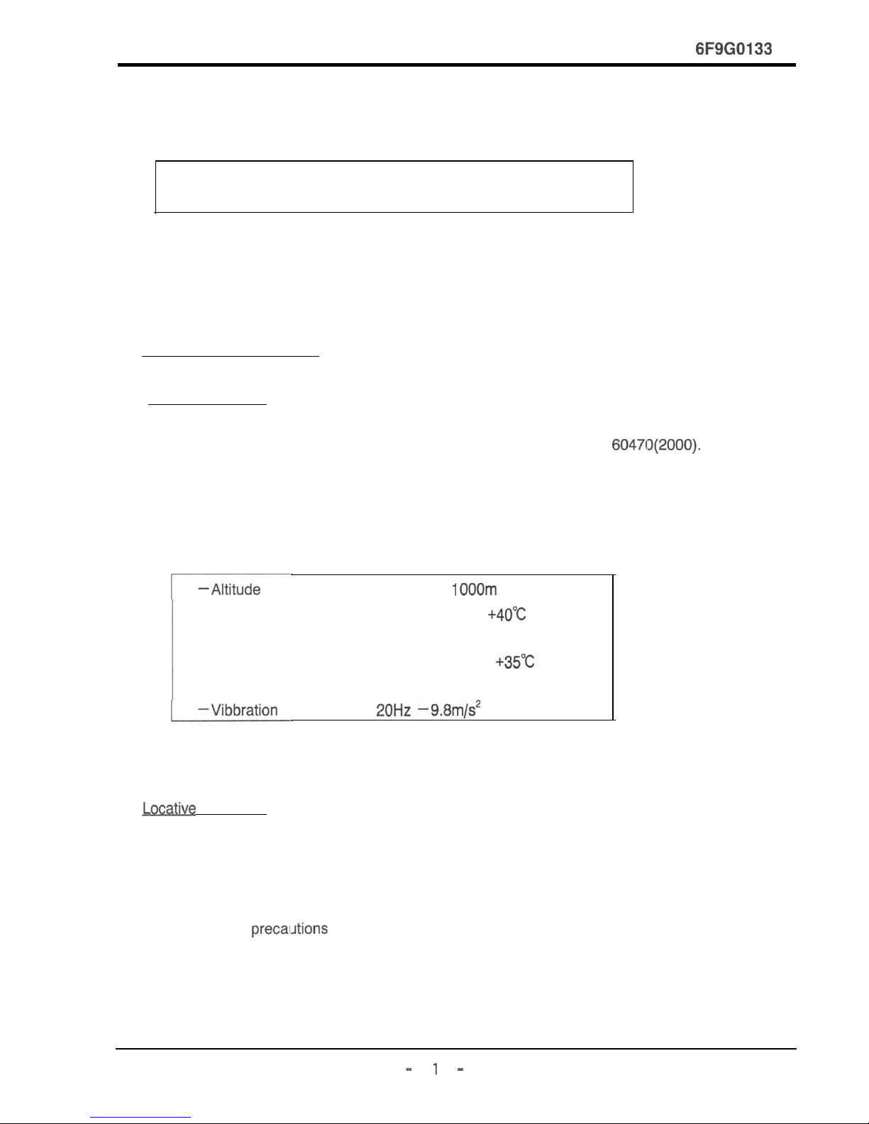
(1) Ambient condition
The type CV vacuum contactor is manufactured in accordance with IEC 60470(2000).
The vacuum contactor should be used in the following conditions.
Table 1
Normal service condition
:
Less than 1
OOOm
-Ambient temperature : -5°C min. to
+4O”C
max.
Its average over a period of 24h
does not exceed
+35-C
-Relative hurnidity : 45% min. to 85% max.
:
20Hz -9.8m/s2
or less
CAUTION:Do not use in condition other than those specified
above , please consult
(2)
Mive
condition
The location where the contactor is to be installed should be free from dust.
Corrosive gas and moisture.
When it is be used in a chemical plant or in outdoor panels,
take necessary precaiJtions against corrosion,
water seepage and condensation.
See page 2.
- 1 -
Page 3
6F9G0133
2.
PRECAUTIONS IN SPECIAL APPLICAJIQN (outdoor cubicle etcJ
In application,
chec:k
the follow items, please carry out the maintenance
frequently. or perform the countermeasure.
(Visual inspection: once a month, regular inspection: once a year)
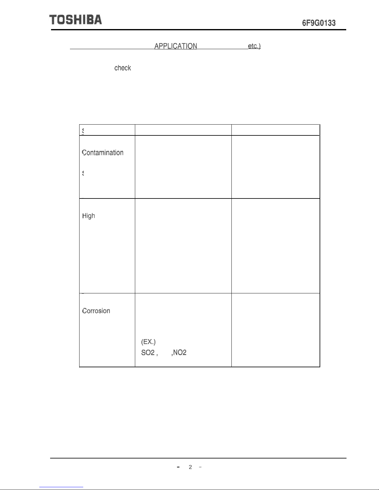
Table 2
Precaution in special application
Special condition instance Caution items
Zontamination
Sea breeze
Dust, iron-dust etc.
is very more place.
Place where suffer the
sea breeze.
Reduction of ventilation
Setting of ventilation for
sea breeze.
Frequent inspection.
iigh
humidity Place where very more
snow and ice.
More humidity.
Place where near the
cooling tower.
Place where cause changing
the temperature suddenly.
Setting the space heater.
Setting the ventilation.
Prevention of flooding
into the cable pit.
Zorrosion gas
Corrosion gas which come
into the airport, chemical
Industry and water cleaning.
W.)
SO2,
Cl2
,N02
Protection from corrosion
gas
Anti-gas treatment.
Examination of changing
of the insulation material.
- 2-
Page 4
TOSHIBA
6F9G0133
3. RECEIVING AND
UNPAKING
WARNING : If any parts are damaged or missing.
Make the following checks after unpacking :
(1) Check if there is any damage , foreign matter trapped , or water seepage
into the contactor.
(2) Check the nameplate to see if the specifications on the plate are correct.
(3) Check the contact wear gauge and control cable.
(4) Check the tripping rod (Latched type).
4. STORAGE AND IHANDLING
When the contactor is to be stored over a long period , the storage area
should be dry and dust free area.
If the contactor is left outdoors or in adverse conditions , corrosion
from gas, rust or insulation deterioration may result.
CAUTION : In handling , do not throw or drop contactor.
The contactor may break.
-
3
-
Page 5
TOSHIBA
6F9G0133
5. INSTALLATION
When installing , protect from dust. Particularly when the contactor
is installed while the building is under construction , shield it from
cement dust and other foreign matter.
The following prec:autions should be taken.
(1) The mounting surface must be horizontal (level : less than
+l
mm).
When the mounting surface is not horizontal , adjust with spacers.
(2) There are four mounting holes.
Use Ml 0 bolts to securely mount the contactor.
(3) In wiring the main circuit terminals, ground terminals and control
circuit , wires should be given sufficient length to be flexible.
The ground wires should be more than 5.5mm in cross section.
(4) Do not mount the contactor with its front inclined downward.
This may result in malfunction.
(5) Do not touch the vacuum interrupter surface with soiled hands.
(6) When it is applied to a capacitor load , be sure to used a space heater
to keep humidity low.
CAUTION : Do not install on energize contactor that has been bad condition.
-A-
Page 6
TOSHIBA
6F9G0133
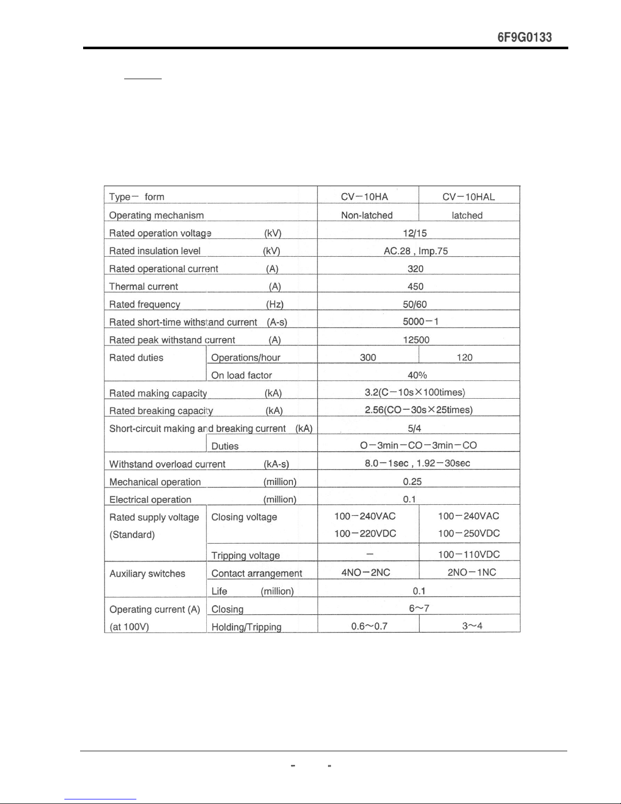
6. RATING
DANGER : Do not exceed the ratings specified on the contactor.
Table 3 Ratings
-
5
-
Page 7

TOSHIBA
6F9G0133
7.
OUTI
INF
DRAYW
- 6-
Page 8

TOSHIBA
6F9G0133
8.
STRUCTRE
Page 9

6F9G0133
9. OPERATION
The drive unit for the electromagnet is installed in the bottom frame.
Molded and wired on the printed circuit.
The closing circuii can be operated using either in AC or DC by the drive unit.
The optional latch trip circuit uses DC as standard.
When a latched contactor is operated using AC power, it is recommended that a
Capacitor trip device be used.
The standard operating voltage is as follows:
Non-latched type(normally energized) :
loo-240
V AC
/lOO-220V
DC
Latched type
:lOO-240V
AC /I 00-250V DC closing voltage
:‘lOO-11OV DC tripping voltage
Diode
(Latched type)
\
\
1 SWITCHING
/+-
‘1
Fig.3 Internal Configuration of Drive Unit
CAUTION : Do not touch the drive unit without trouble.
Page 10

TOSHIBA
6F9G0133
(1)
CONNECTION OF CONTROL POWER SUPPLY
Fig.4 and Fig.5 show the internal connections of the normally energized type
latched type respectively.
According to there figures, connection should be made of the control power
supply and open / close command contact (power relay contact).
Fig.4 Internal connection of the normally energized type.
Fig.5 tnternal connection of latched type.
- 9-
Page 11

TOSHIBA
6F9G0133
(2) STANDARD
OiPERATlON
CIRCUIT
Shown below are the vacuum contactor and its auxiliary circuits (control and
monitoring).
Fig.5 represents the standard operation circuit of the normally energized type
and Fig.6 the latched type.
Wiring should be done according to these circuit diagrams.
Y
Fig.6 Standard operation circuit of normally energized type.
NOTE:.
Be sure to use quickly AC auxiliary relay contact NO for self-holding.
If the self-holding circuit is formed by using the auxiliary contact No
of the vacuum contactor , welding of the main contact may result when
the start button is pushed incompletely(refer to
*I
in Fig.6).
-
10
-
Page 12

TOSHIBA
6F9G0133
TII
TInTI, T18 T11
(a) Shunt trip
(b) Capacitor trip
Fig.7 Standard operation circuit of latched type.
NOTE : 0 Electrical trip-free circuit must be prepared outside the contactor.
0
A stable DC power source such as battery is recommended for the
control circuit.
If DC power source is not available, employ a AC closing and a
Capacitor trip.
l
Be sure to use the control connector between No.3 and No.13
(auxiliary contact) for trip circuit.
Cclnnect the control connector between No.5 and No.1 5
(auxiliary contact) for control relay circuit.
-
11
-
Page 13

TOSHIBA
6F9G0133
1 0.
Dal
operation
Warning : Make sure main power is OFF.
After mounting and wiring of the vacuum contactor, make the following inspections.
1)
Check for any loose connections.
2) Check for any wiring errors. Perform this test with only the control circuit energized.
confirm that the operation is correct. For the latched type contactor, check that the
latch correctly engages and trips when the close/trip signals are applied. Also,
manually trip the contactor using trip lever to verify proper operation.
-
12
-
Page 14

TOSHIBA
6F9G0133
1 1 . INSPECTION AND MAINTFNACE
To maintain the function and performance of the vacuum contactor for a long period
of time, the following inspections and maintenance procedures are recommended.
The intervals between inspections may vary depending on the conditions of use and
the environment under which the contactor is used. The initial inspection should be
carried out within one year of the start of equipment operation, and the succeeding
check intervals should be determined according to the result of the initial inspection.
See Section 2 for use under special environment as in outdoor cubicles.
(1)
Patrol
Inspection(every
l-6 months)
With the cubicle energized, visually check from out side the cubicle according to
the check list of Table
45.
WARNING : When opening the door of the cubicle, do not come close
to danger area.
Table 4 Patrol inspection items
Check item
t
Abnormal noise
Abnormal smell
What to check
Check if corona discharges or operation
magnets are not
Check if corona discharges or overheat are
not producing abnormal smell.
Table 5 Patrol inspection items(cont.)
Is there not any discoloration due to
-
13
-
Page 15

TOSHIBA
6F9G0133
(2)
Periodical inspection/Detailed Inspection(every l-2 years or every
20,000 operations)
The faciliiy should be removed out of service and perform inspection
According to the instruction given in Table 6.
: Contact with energized components can cause severe injury
or death.
Turn-off and lock out primary and control circuit before servicing.
-
14
Page 16

TOSHIBA
6F9G0133
Table 6 Periodical inspection and detailed inspection
,ontactor
as
dust adheres to the
Under dusty environments,
frequent inspection
check correct
and burned parts.
and coupling conductor,
ause and replace
Check contact wear and
inform the maker.
-
15
Page 17

TOSHIBA
6F9G0133
Check for discoloration
Replace if damage
Overheat, discoloration. Replace if abnormal
resistance between
phases, between
electrodes and between
circuits and ground.
(Measurement is taken
below the standard
level, investigate the
necessary, replace
Measure insulation
resistance between
circuits and ground.
(Measurement is taken
More than 1 M
Q
strength between phases,
between electrodes and
between circuits and
inform the maker.
Open/close operation
operation by electric
operation test to confirm
check and repair.
Remarks: For extraordinary (unscheduled) inspections , pick up check items from the above table.
-
16
Page 18

6F9G0133
Table 7
Gap/wipe standard value
Part:
Vacuum
t
interrupter
12.
.Q3lTERIA FOR DURABILITY
(1) Electrical service
lift?
The electrical
servic:e
life of the vacuum interrupter is defined by the electrode wear the
number of open/close operations (mechanical life).
To determine the electrode wear, measure the gap between the lever and washer
(dimension A) in a closed start , as shown in Figure8. With the vacuum interrupter
closed, if a contact ‘wear gauge or a 1 .Omm thickness gauge cannot be inserted ,
this means the end of life is reached.
For the components listed below, replacement or detailed inspection and cleaning
are recommended after the indicated number of operations.
Table 8 Electrical service life
Vacu
t
Auxili
Drive
Movs
Hence, parts should be replaced around electrical service life operations.
CONlACT
SPR I
WASHER
(MB)
Fig.8
Parts to be inspected
-
17
-
Page 19

TOSHIBA
6F9G0133
(2) Mechanical service life
The normally energized type has the mechanical service life of 0.25 million operations ,
and the latch type 0.25 million operations. (The mechanical service life of the vacuum
interrupter is 100,000 operations.)
For the components listed below, replacement or detailed inspection and cleaning are
recommended after the indicated number of operations.
‘Table 9
Recommended replacement park
- 18.-
Page 20

TOSHIBA CORPORATION
 Loading...