

Page 1

TOSHIBA Digital Solutions Division
Digital Business Telephone Systems
CTX28, CTX100-S, CTX100 and CTX670
Installation and Maintenance
Manual
June 2004
Page 2

Strata CTX28, CTX100 and CTX670
General End User Information
The Strata CTX28, CTX100 or CTX670 Digital Business Telephone System is
registered in accordance with the provisions of Part 68 of the Federal Communications
Commission’s Rules and Regulations.
FCC Requirements
Means of Connection: The Federal Communications Commission (FCC) has
established rules which permit the Strata CTX28, CTX100 or CTX670 system to be
connected directly to the telephone network. Connection points are provided by the
telephone company—connections for this type of customer-provided equipment will
not be provided on coin lines. Connections to party lines are subject to state tariffs.
Incidence of Harm: If the system is malfunctioning, it may also be disrupting the
telephone network. The system should be disconnected until the problem can be
determined and repaired. If this is not done, the telephone company may temporarily
disconnect service. If possible, they will notify you in advance, but, if advance notice is
not practical, you will be notified as soon as possible. You will be informed of your
right to file a complaint with the FCC.
Service or Repair: For service or repair, contact your local Toshiba telecommunications
distributor. To obtain the nearest Toshiba telecommunications distributor in your area,
log onto www.toshiba.com/taistsd/locator.htm or call (800) 222-5805 and ask for a
Toshiba Telecom Dealer.
Telephone Network Compatibility: The telephone company may make changes in its
facilities, equipment, operations, and procedures. If such changes affect the
compatibility or use of the Strata CTX28, CTX100 or CTX670 system, the telephone
company will notify you in advance to give you an opportunity to maintain
uninterrupted service.
Notification of Telephone Company: Before connecting a Strata CTX28, CTX100 or
CTX670 system to the telephone network, the telephone company may request the
following:
1. Your telephone number.
2. FCC registration number:
• Strata CTX28, CTX100 or CTX670 may be configured as a Key, Hybrid or PBX
telephone system. The appropriate configuration for your system is dependent
upon your operation of the system.
• If the operation of your system is only manual selection of outgoing lines, it may
be registered as a Key telephone system.
• If your operation requires automatic selection of outgoing lines, such as dial
access, Least Cost Routing, Pooled Line Buttons, etc., the system must be
registered as a Hybrid telephone system. In addition to the above, certain
features (tie Lines, Off-premises Stations, etc.) may also require Hybrid
telephone system registration in some areas.
• If you are unsure of your type of operation and/or the appropriate FCC
registration number, contact your local Toshiba telecommunications distributor
for assistance.
• CTX28 FCC/ACTA Registration Numbers
Hybrid: CJ6MF03BDTCHS28, fully-protected multifunction systems
Key: CJ6KD03BDTCHS28, key systems for analog applications
• CTX100 Registration Numbers
PBX: CJ6MUL-35931-PF-E, fully-protected PBXs
Hybrid: CJ6MUL-35930-MF-E, fully-protected multifunction systems
Key: CJ6MUL-35929-KF-E, fully-protected telephone key systems
• CTX670 Registration Numbers
PBX: CJ6MUL-35934-PF-E, fully-protected PBXs
Hybrid: CJ6MUL-35933-MF-E, fully-protected multifunction systems
Key: CJ6MUL-35932-KF-E, fully-protected telephone key systems
• Ringer equivalence number: 0.3B. The ringer equivalence number (REN) is
useful to determine the quantity of devices which you may connect to your
telephone line and still have all of those devices ring when your number is
called. In most areas, but not all, the sum of the RENs of all devices connected to
one line should not exceed five (5.0B). To be certain of the number of devices
you may connect to your line, as determined by the REN, you should contact
your local telephone company to ascertain the maximum REN for your calling
area.
3. Network connection information USOC jack required: RJ11/14C,
RJ21/2E/2F/2G/2HX/RJ49C (see Network Requirements in this document). Items
2, 3 and 4 are also indicated on the equipment label.
4. Authorized Network Parts: 02LS2/GS2, 02RV2-T/O, OL13C/B, T11/12/31/32M,
04DU9-BN/DN/1SN, 02IS5, 04DU9-BN/DN/1SN1ZN
Radio Frequency Interference
Warning: This equipment generates, uses, and can radiate radio frequency energy and if
not installed and used in accordance with the manufacturer ’s instruction manual, may
cause interference to radio communications. It has been tested and found to comply
with the limits for a Class A computing device pursuant to Subpart J of Part 15 of FCC
Rules, which are designed to provide reasonable protection against such interference
when operated in a commercial environment. Operation of this equipment in a
residential area is likely to cause interference, in which case, the user, at his/her own
expense, will be required to take whatever measures may be required to correct the
interference.
This system is listed with Underwriters Laboratory.
UL Requirement: If wiring from any telephone exits the building or is
subject to lightning or other electrical surges, then secondary protection
is required. Secondary protection is also required on DID, OPS, and Tie
lines. (Additional information is provided in this manual.)
U
L
®
Important Notice — Music-On-Hold
In accordance with U.S. Copyright Law, a license may be required from
the American Society of Composers, Authors and Publishers, or other similar
organization, if radio or TV broadcasts are transmitted through the music-on-hold
feature of this telecommunication system. Toshiba America Information Systems, Inc.,
hereby disclaims any liability arising out of the failure to obtain such a license.
CP01, Issue 8, Part I Section 14.1
Notice: The Industry Canada label identifies certified equipment. This certification
means that the equipment meets certain telecommunications network protective,
operational and safety requirements as prescribed in the appropriate Terminal
Equipment Technical Requirements document(s). The Department does not guarantee
the Equipment will operate to the user’s satisfaction.
Before installing this equipment, users should ensure that it is permissible to be
connected to the facilities of the local telecommunications company. The equipment
must also be installed using an acceptable method of connection. The customer should
be aware that compliance with the above conditions may not prevent degradation of
service in some situations.
Repairs to certified equipment should be coordinated by a representative designated by
the supplier. Any repairs or alterations made by the user to this equipment, or
equipment malfunctions, may give the telecommunications company cause to request
the user to disconnect the equipment.
Users should ensure for their own protection that the electrical ground connections of
the power utility, telephone lines and internal metallic water pipe system, if present, are
connected together. This precaution may be particularly important in rural areas.
CAUTION! Users should not attempt to make such connections themselves, but
CP01, Issue 8, Part I Section 14.2
Notice: The Ringer Equivalence Number (REN) assigned to each terminal device
provides an indication of the maximum number of terminals allowed to be connected to
a telephone interface. The terminal on an interface may consist of any combination of
devices subject only to the requirement that the sum of the Ringer Equivalence
Numbers of all the Devices does not exceed 5.
should contact the appropriate electric inspection authority, or
electrician, as appropriate.
Publication Information
Toshiba America Information Systems, Inc., Digital Solutions Division, reserves the
right, without prior notice, to revise this information publication for any reason,
including, but not limited to, utilization of new advances in the state of technical arts or
to simply change the design of this document.
Further, Toshiba America Information Systems, Inc., Digital Solutions Division, also
reserves the right, without prior notice, to make such changes in equipment design or
components as engineering or manufacturing methods may warrant.
CTX-MA-IM/MT-VE
Version E, June 2004
© Copyright 2004
Toshiba America Information Systems, Inc.
Digital Solutions Division
All rights reserved. No part of this manual, covered by the copyrights hereon, may be
reproduced in any form or by any means—graphic, electronic, or mechanical,
including recording, taping, photocopying, or information retrieval systems—without
express written permission of the publisher of this material.
Strata and SmartMedia are registered trademarks of Toshiba Corporation.
Stratagy is a registered trademark of Toshiba America Information Systems, Inc.
Trademarks, registered trademarks, and service marks are the property of their
respective owners.
Page 3

TOSHIBA AMERICA INFORMATION SYSTEMS, INC. (“TAIS”)
Digital Solutions Division License Agreement
IMPORTANT: THIS LICENSE AGREEMENT (“AGREEMENT”) IS A LEGAL AGREEMENT BETWEEN YOU (“YOU”) AND TAIS. CAREFULLY READ THIS LICENSE AGREEMENT. USE OF ANY
SOFTWARE OR ANY RELATED INFORMATION (COLLECTIVELY, “SOFTWARE”) INSTALLED ON OR SHIPPED WITH A TAIS DIGITAL SOLUTIONS PRODUCT OR OTHERWISE MADE AVAILABLE TO
YOU BY TAIS IN WHATEVER FORM OR MEDIA, WILL CONSTITUTE YOUR ACCEPTANCE OF THESE TERMS, UNLESS SEPARATE TERMS ARE PROVIDED BY THE SOFTWARE SUPPLIER. IF
YOU DO NOT AGREE WITH THE TERMS OF THIS LICENSE AGREEMENT, DO NOT INSTALL, COPY OR USE THE SOFTWARE AND PROMPTLY RETURN IT TO THE LOCATION FROM WHICH YOU
OBTAINED IT IN ACCORDANCE WITH APPLICABLE RETURN POLICIES. EXCEPT AS OTHERWISE AUTHORIZED IN WRITING BY TAIS, THIS SOFTWARE IS LICENSED FOR DISTRIBUTION ONLY
TO END-USERS PURSUANT TO THIS LICENSE AGREEMENT.
1. License Grant. The Software is not sold; it is licensed upon payment of applicable charges. TAIS grants to you a personal, non-transferable and non-exclusive right to use the copy of the Software
provided under this License Agreement. You agree you will not copy the Software except as necessary to use it on one TAIS system at a time at one location. Modifying, translating, renting, copying,
distributing, transferring or assigning all or part of the Software, or any rights granted hereunder, to any other persons and removing any proprietary notices, labels or marks from the Software is strictly
prohibited; You agree violation of such restrictions will cause irreparable harm to TAIS and provide grounds for injunctive relief, without notice, against You or any other person in possession of the Software.
You and any other person whose possession of the software violates this License Agreement shall promptly surrender possession of the Software to TAIS, upon demand. Furthermore, you hereby agree not
to create derivative works based on the Software. TAIS reserves the right to terminate this license and to immediately repossess the software in the event that You or any other person violates this License
Agreement.
2. Intellectual Property. You acknowledge that no title to the intellectual property in the Software is transferred to you. You further acknowledge that title and full ownership rights to the Software will remain
the exclusive property of TAIS and/or its suppliers, and you will not acquire any rights to the Software, except the license expressly set forth above. You will not remove or change any proprietary notices
contained in or on the Software. The Software is protected under US patent, copyright, trade secret, and/or other proprietary laws, as well as international treaties. Any transfer, use, or copying of the
software in violation of the License Agreement constitutes copyright infringement. You are hereby on notice that any transfer, use, or copying of the Software in violation of this License Agreement constitutes
a willful infringement of copyright.
3. No Reverse Engineering. You agree that you will not attempt, and if you employ employees or engage contractors, you will use your best efforts to prevent your employees and contractors from
attempting to reverse compile, reverse engineer, modify, translate or disassemble the Software in whole or in part. Any failure to comply with the above or any other terms and conditions contained herein
will result in the automatic termination of this license and the reversion of the rights granted hereunder back to TAIS.
4. Limited Warranty. THE SOFTWARE IS PROVIDED “AS IS” WITHOUT WARRANTY OF ANY KIND. TO THE MAXIMUM EXTENT PERMITTED BY APPLICABLE LAW, TAIS AND ITS SUPPLIERS
DISCLAIM ALL WARRANTIES WITH REGARD TO THE SOFTWARE, EITHER EXPRESS OR IMPLIED, INCLUDING, BUT NOT LIMITED TO, THE WARRANTY OF NON-INFRINGEMENT OF THIRD
PARTY RIGHTS, THE WARRANTY OF YEAR 2000 COMPLIANCE, AND THE IMPLIED WARRANTIES OF MERCHANTABILITY AND FITNESS FOR A PARTICULAR PURPOSE. THE ENTIRE RISK AS
TO THE QUALITY AND PERFORMANCE OF THE SOFTWARE IS WITH YOU. NEITHER TAIS NOR ITS SUPPLIERS WARRANT THAT THE FUNCTIONS CONTAINED IN THE SOFTWARE WILL MEET
YOUR REQUIREMENTS OR THAT THE OPERATION OF THE SOFTWARE WILL BE UNINTERRUPTED OR ERROR-FREE. HOWEVER, TAIS WARRANTS THAT ANY MEDIA ON WHICH THE
SOFTWARE IS FURNISHED IS FREE FROM DEFECTS IN MATERIAL AND WORKMANSHIP UNDER NORMAL USE FOR A PERIOD OF NINETY (90) DAYS FROM THE DATE OF DELIVERY TO
YOU.
5. Limitation Of Liability. TAIS’ ENTIRE LIABILITY AND YOUR SOLE AND EXCLUSIVE REMEDY UNDER THIS LICENSE AGREEMENT SHALL BE AT TAIS’ OPTION REPLACEMENT OF THE MEDIA OR
REFUND OF THE PRICE PAID. TO THE MAXIMUM EXTENT PERMITTED BY APPLICABLE LAW, IN NO EVENT SHALL TAIS OR ITS SUPPLIERS BE LIABLE TO YOU FOR ANY CONSEQUENTIAL,
SPECIAL, INCIDENTAL OR INDIRECT DAMAGES FOR PERSONAL INJURY, LOSS OF BUSINESS PROFITS, BUSINESS INTERRUPTION, LOSS OF BUSINESS INFORMATION/DATA, OR ANY
OTHER PECUNIARY LOSS OF ANY KIND ARISING OUT OF THE USE OR INABILITY TO USE THE SOFTWARE, EVEN IF TAIS OR ITS SUPPLIER HAS BEEN ADVISED OF THE POSSIBILITY OF
SUCH DAMAGES. IN NO EVENT SHALL TAIS OR ITS SUPPLIERS BE LIABLE FOR ANY CLAIM BY A THIRD PARTY.
6. State/Jurisdiction Laws. SOME STATES/JURISDICTIONS DO NOT ALLOW THE EXCLUSION OF IMPLIED WARRANTIES OR LIMITATIONS ON HOW LONG AN IMPLIED WARRANTY MAY LAST, OR
THE EXCLUSION OR LIMITATION OF INCIDENTAL OR CONSEQUENTIAL DAMAGES, SO SUCH LIMITATIONS OR EXCLUSIONS MAY NOT APPLY TO YOU. THIS LIMITED WARRANTY GIVES YOU
SPECIFIC RIGHTS AND YOU MAY ALSO HAVE OTHER RIGHTS WHICH VARY FROM STATE/JURISDICTION TO STATE/JURISDICTION.
7. Export Laws. This License Agreement involves products and/or technical data that may be controlled under the United States Export Administration Regulations and may be subject to the approval of the
United States Department of Commerce prior to export. Any export, directly or indirectly, in contravention of the United States Export Administration Regulations, or any other applicable law, regulation or
order, is prohibited.
8. Governing Law. This License Agreement will be governed by the laws of the State of California, United States of America, excluding its conflict of law provisions.
9. United States Government Restricted Rights. The Software is provided with Restricted Rights. Use, duplication, or disclosure by the United States Government, its agencies and/or instrumentalities is
subject to restrictions as set forth in subparagraph (c)(1)(ii) of The Rights in Technical Data and Computer Software Clause at DFARS 252.227-7013 (October 1988) or subparagraphs (c)(1) and (2) of the
Commercial Computer Software - Restricted Rights at 48 CFR 52.227-19, as applicable.
10. Severability. If any provision of this License Agreement shall be held to be invalid, illegal or unenforceable, the validity, legality and enforceability of the remaining provisions hereof shall not in any way
be affected or impaired.
11. No Waiver. No waiver of any breach of any provision of this License Agreement shall constitute a waiver of any prior, concurrent or subsequent breach of the same or any other provisions hereof, and no
waiver shall be effective unless made in writing and signed by an authorized representative of the waiving party.
YOU ACKNOWLEDGE THAT YOU HAVE READ THIS LICENSE AGREEMENT AND THAT YOU UNDERSTAND ITS PROVISIONS. YOU AGREE TO BE BOUND BY ITS TERMS AND CONDITIONS. YOU
FURTHER AGREE THAT THIS LICENSE AGREEMENT CONTAINS THE COMPLETE AND EXCLUSIVE AGREEMENT BETWEEN YOU AND TAIS AND SUPERSEDES ANY PROPOSAL OR PRIOR
AGREEMENT, ORAL OR WRITTEN, OR ANY OTHER COMMUNICATION RELATING TO THE SUBJECT MATTER OF THIS LICENSE AGREEMENT.
Toshiba America Information Systems, Inc.
Digital Solutions Division
9740 Irvine Boulevard
Irvine, California 92618-1697
United States of America
DSD 060204
5932
Page 4

Toshiba America Information Systems, Inc.
Digital Solutions Division
Limited Warranty
Toshiba America Information Systems, Inc., (“TAIS”) warrants that this telephone equipment (except for fuses,
lamps, and other consumables) will, upon delivery by TAIS or an authorized TAIS dealer to a retail customer in new
condition, be free from defects in material and workmanship for twenty-four (24) months after delivery. This
warranty is void (a) if the equipment is used under other than normal use and maintenance conditions, (b) if the
equipment is modified or altered, unless the modification or alteration is expressly authorized by TAIS, (c) if the
equipment is subject to abuse, neglect, lightning, electrical fault, or accident, (d) if the equipment is repaired by
someone other than TAIS or an authorized TAIS dealer, (e) if the equipment’s serial number is defaced or missing, or
(f) if the equipment is installed or used in combination or in assembly with products not supplied by TAIS and which
are not compatible or are of inferior quality, design, or performance.
The sole obligation of TAIS or Toshiba Corporation under this warranty, or under any other legal obligation with
respect to the equipment, is the repair or replacement by TAIS or its authorized dealer of such defective or missing
parts as are causing the malfunction with new or refurbished parts (at their option). If TAIS or one of its authorized
dealers does not replace or repair such parts, the retail customer’s sole remedy will be a refund of the price charged by
TAIS to its dealers for such parts as are proven to be defective, and which are returned to TAIS through one of its
authorized dealers within the warranty period and no later than thirty (30) days after such malfunction, whichever
first occurs.
Under no circumstances will the retail customer or any user or dealer or other person be entitled to any direct, special,
indirect, consequential, or exemplary damages, for breach of contract, tort, or otherwise. Under no circumstances will
any such person be entitled to any sum greater than the purchase price paid for the item of equipment that is
malfunctioning.
To obtain service under this warranty, the retail customer must bring the malfunction of the machine to the attention
of one of TAIS’ authorized dealers within the twenty-four (24) month period and no later than thirty (30) days after
such malfunction, whichever first occurs. Failure to bring the malfunction to the attention of an authorized TAIS
dealer within the prescribed time results in the customer being not entitled to warranty service.
THERE ARE NO OTHER WARRANTIES FROM EITHER TOSHIBA AMERICA INFORMATION SYSTEMS,
INC., OR TOSHIBA CORPORATION WHICH EXTEND BEYOND THE FACE OF THIS WARRANTY. ALL
OTHER WARRANTIES, EXPRESS OR IMPLIED, INCLUDING THE WARRANTIES OF
MERCHANTABILITY, FITNESS FOR A PARTICULAR PURPOSE, AND FITNESS FOR USE, ARE
EXCLUDED.
No TAIS dealer and no person other than an officer of TAIS may extend or modify this warranty. No such
modification or extension is effective unless it is in writing and signed by the vice president and general manager,
Digital Solutions Division.
Page 5

Contents
Introduction
Organization ........................................................................................................................................xiii
Conventions .........................................................................................................................................xiv
Related Documents/Media ...................................................................................................................xv
General Description ....................................................................................................................... xv
Programming Manual ....................................................................................................................xv
User Guides ................................................................................................................................... xv
Quick Reference Guides ................................................................................................................ xv
CD-ROMs ...................................................................................................................................... xv
Chapter 1 – CTX28 Installation
Inspection ............................................................................................................................................1-1
Packaging and Storage ........................................................................................................................1-1
CTX28 FCC/ACTA Registration Numbers ........................................................................................1-1
Site Requirements ...............................................................................................................................1-2
Input Power ...................................................................................................................................1-2
Clearance and Location ................................................................................................................1-2
AC Power and Grounding Requirements ............................................................................................1-4
AC Power Ground Test ................................................................................................................1-5
Installing the CTX28 Cabinet ............................................................................................................. 1-6
Step 1: Mount the Cabinet on the Wall .........................................................................................1-6
PCB Installation ............................................................................................................................1-8
Step 2: Set Jumpers on the GMAU1A (Motherboard) ...............................................................1-10
Step 3: Install the GVMU1A Voice Mail PCB (optional) ..........................................................1-12
Step 4: Install the GCTU1A (Processor) ....................................................................................1-14
Step 5: Install the GCDU1A (DKT and Loop Start Interface) ...................................................1-16
Step 6: Install the GSTU1A ........................................................................................................1-17
Step 7: Install the GETS1A ........................................................................................................1-17
Step 8: Install the BSIS1A (optional) .........................................................................................1-18
Step 9: Install the HPFB-6 (Reserve Power Battery/Charger) ...................................................1-18
Step 10: Install Wiring ................................................................................................................1-19
Digital Telephone Connection ..........................................................................................................1-21
Loop Limits ......................................................................................................................................1-22
CTX28 Secondary Protection ...........................................................................................................1-23
MDF Wiring ......................................................................................................................................1-24
GVMU Administration PC Connections ..........................................................................................1-25
Strata CTX I&M 06/04 i
Page 6

Contents
Chapter 2 – Strata CTX Configuration
Chapter 2 – Strata CTX Configuration
Strata CTX100-S/CTX100 Overview .................................................................................................2-1
CTX100-S and CTX100 Processors ...................................................................................................2-2
CPU/Memory ................................................................................................................................2-2
Large Scale Integrated (LSI) Circuits ...........................................................................................2-2
Memory Protection Battery ..........................................................................................................2-2
Relay Control Interface ................................................................................................................2-2
External Page Interface .................................................................................................................2-2
Music-on-hold/Background Music Interface ................................................................................2-3
SmartMedia Memory ...................................................................................................................2-3
CTX100 Processor Optional Subassemblies ................................................................................2-3
CTX100 Cabinet Slots ........................................................................................................................2-3
Base Cabinet .................................................................................................................................2-3
Expansion Cabinets ......................................................................................................................2-3
CTX100-S/CTX100 License Control .................................................................................................2-4
Licensed Software Options ...........................................................................................................2-4
Strata CTX670 Overview ....................................................................................................................2-5
CTX670 Processor PCBs ....................................................................................................................2-5
CPU/Memory ................................................................................................................................2-5
Large-scale Integrated (LSI) circuits ............................................................................................2-6
Memory Protection Battery ..........................................................................................................2-6
Music-on-hold/Background Music Interface ................................................................................2-6
SmartMedia Memory ....................................................................................................................2-6
Network Interface .........................................................................................................................2-6
CTX670 Processor PCB Subassemblies .......................................................................................2-7
CTX670 License Control ....................................................................................................................2-7
Licensed Software Options ...........................................................................................................2-7
CTX670 Cabinet Slots ........................................................................................................................2-8
Base Cabinet .................................................................................................................................2-8
Expansion Cabinets ......................................................................................................................2-8
CTX670 Remote Expansion Cabinet ..................................................................................................2-9
System Capacities ...............................................................................................................................2-9
Universal Slot PCBs ..........................................................................................................................2-14
Station, Line and Option PCBs ...................................................................................................2-14
Functional Block Diagrams ...............................................................................................................2-18
Worksheet Description ......................................................................................................................2-22
CTX670 Remote Cabinet Configuration Considerations .................................................................2-22
Component Worksheets ..............................................................................................................2-22
Worksheet 1: Toshiba DKT and IP Telephones ..............................................................................2-23
Worksheet 2: Standard Telephone, Stratagy DK, IVP8 ...................................................................2-24
Worksheet 3: CO Line ....................................................................................................................2-25
Worksheet 4: Page/MOH/Control Relay ..........................................................................................2-26
Worksheet 5: Strata CTX100 Cabinet Slots ......................................................................................2-26
CTX100 Max. Capacity Configuration Examples ............................................................................2-28
Digital Telephones and Loop Start Lines With or Without Caller ID ........................................2-28
Analog Loop Start Lines with or without Caller ID ...................................................................2-29
CTX100 Base Only: Digital Telephones and T1 and/or PRI lines .............................................2-32
CTX100 Base & Expansion: Digital Telephones and T1 and/or PRI lines ................................2-33
CTX100 Base Only: Digital Telephones and Analog Tie, DID, and/or Ground Start Lines .....2-34
ii Strata CTX I&M 06/04
Page 7

Chapter 3 – Strata CTX100-S/CTX100 Installation
CTX100: Analog Tie, DID and/or Ground Start Lines ..............................................................2-35
Worksheet 6: Strata CTX670 Cabinet Slots ......................................................................................2-37
PCB Placement Guidelines .........................................................................................................2-38
Worksheet 7 – System Power Factor Check .....................................................................................2-42
Telephone/Device Power Factors ...............................................................................................2-44
Cabinet Power Factor Check .............................................................................................................2-45
CTX100 ...................................................................................................................................... 2-45
CTX670 ......................................................................................................................................2-46
Worksheet 8 – CTX Primary AC and Reserve Power ......................................................................2-47
CTX100 AC Power Considerations ...........................................................................................2-47
CTX670 AC Power Considerations ...........................................................................................2-47
Reserve Power (CTX100 and CTX670) ...........................................................................................2-48
Primary/Reserve Power Cabinet Hardware ......................................................................................2-49
CTX670 Cabinet AC Power Component Requirements for Wall Mounted Systems ................2-52
Worksheet 9 – Software Licenses .....................................................................................................2-54
Hardware Compatibility ....................................................................................................................2-55
Chapter 3 – Strata CTX100-S/CTX100 Installation
Inspection ............................................................................................................................................3-1
Packaging and Storage ........................................................................................................................3-1
Site Requirements ...............................................................................................................................3-1
Input Power ...................................................................................................................................3-1
Cabinet Size and Weight ..............................................................................................................3-2
Clearance and Location ................................................................................................................3-2
Environmental Considerations .....................................................................................................3-4
AC Power and Grounding Requirements ............................................................................................3-4
Power Considerations ...................................................................................................................3-4
AC Power and Third-wire Ground Test .......................................................................................3-5
Alternate or Additional Ground ....................................................................................................3-5
Installing the CTX100 Cabinet ...........................................................................................................3-6
Step 1: Remove Cabinet Covers ...................................................................................................3-6
Step 2: Remove the Back Cover from the Cabinet(s) ..................................................................3-6
Step 3: Check the Base/Expansion Power Supply Jumper Plug ..................................................3-7
Step 4: Mount the Base Cabinet ...................................................................................................3-7
Step 5: Mount the Expansion Cabinet (if required) ......................................................................3-9
Step 6: Install Reserve Power .....................................................................................................3-10
Step 7: Check Power Supply Circuit Breakers and Fuses ..........................................................3-15
Step 8: Set Jumpers and Install Option PCBs onto the ACTU ...................................................3-19
Step 9: Install the Main Processor (ACTU) PCB .......................................................................3-21
Step 10: Install Other PCBs into the Cabinet(s) .........................................................................3-22
Step 11: Attach and Route PCB Cables ......................................................................................3-23
Contents
Chapter 4 – Strata CTX670 Installation
Inspection ............................................................................................................................................4-1
Packaging and Storage ........................................................................................................................4-1
Site Requirements ...............................................................................................................................4-2
Input Power ...................................................................................................................................4-2
Clearance and Location ................................................................................................................4-2
Power Considerations ..........................................................................................................................4-4
Reserve Power ..............................................................................................................................4-4
Strata CTX I&M 06/04 iii
Page 8

Contents
Chapter 5 – Rack Mount Cabinets
FCC Registration Information .............................................................................................................4-5
Cabinet Installation Considerations ....................................................................................................4-6
Recommended Installation Sequence ...........................................................................................4-6
Step 1: Install Power Supply ...............................................................................................................4-6
Check the -24 Volt Circuit Breakers ............................................................................................4-7
Check the Power Factor Indicator and Reset Button ....................................................................4-8
Power Supply (BPSU672) Removal .............................................................................................4-8
Power Supply Replacement ..........................................................................................................4-8
Step 2: Mount Cabinets......................................................................................................................4-10
Wall Mounting the Base (Top) Cabinet .....................................................................................4-10
Wall Mounting Expansion Cabinets ...........................................................................................4-11
Step 3: Install Data Cables.................................................................................................................4-16
Step 4: Ground the System.................................................................................................................4-18
Step 5: Install AC Power Components...............................................................................................4-20
AC Power Requirements ............................................................................................................4-20
Cabinet AC Power Component Description ...............................................................................4-21
AC/Reserve Power and Data Cabling Overview ........................................................................4-22
Cabinet AC Power Considerations .............................................................................................4-24
Cabinet AC Power Component Requirements for Wall Mounted Systems ...............................4-24
Step 6: Install Reserve Power ............................................................................................................4-29
Reserve Battery Cabinet Components/Cables ............................................................................4-30
Reserve Power for One or Two Cabinets (Wall Mount) ............................................................4-30
Reserve Power for Three or More Cabinets (Wall Mount) ........................................................4-31
Cabinet Floor Mounting ............................................................................................................. 4-33
Reserve Power/AC Wiring for Three or More Cabinets (Floor Mount) ....................................4-42
Step 7: Install Processor and Universal PCBs....................................................................................4-43
PCB Installation Considerations .................................................................................................4-43
PCB Option Considerations ........................................................................................................4-43
BCTU1A/BEXU1A Installation .................................................................................................4-44
BECU/BBCU Installation ...........................................................................................................4-50
Remote Expansion Cabinet Unit .......................................................................................................4-55
Remote Cabinet Installation Instructions ...................................................................................4-56
Status Indicators .........................................................................................................................4-60
Monitor Port Communication Parameters ..................................................................................4-61
Monitor Port Pin Assignments ...................................................................................................4-61
Chapter 5 – Rack Mount Cabinets
Basic Specifications ............................................................................................................................5-1
Inspection ............................................................................................................................................5-2
Site Requirements ...............................................................................................................................5-2
Space .............................................................................................................................................5-2
Ventilation ....................................................................................................................................5-2
Input Power ...................................................................................................................................5-3
Environmental Conditions ............................................................................................................5-3
Location ........................................................................................................................................5-3
Power Considerations ..........................................................................................................................5-3
Reserve Power ..............................................................................................................................5-3
FCC Registration Information .............................................................................................................5-4
Step 1: Prior to Cabinet Installation ....................................................................................................5-5
Step 1A:Assemble Rack ............................................................................................................... 5-5
iv Strata CTX I&M 06/04
Page 9

Contents
Chapter 6 – PCB Installation
Step 1B:Move Flange Position (Optional) ................................................................................... 5-5
Step 2: Install First Cabinet..................................................................................................................5-5
Step 2A:Take Off Front and Back Covers.................................................................................... 5-6
Step 2B:Take Off Base of Cabinet ............................................................................................... 5-6
Step 2C:Attach Cabinet to Rack................................................................................................... 5-6
Step 2D:Reattach Cabinet to Base................................................................................................ 5-8
Step 3: Install Remaining Cabinet(s) ...................................................................................................5-8
Step 3A:Take Off Front and Back Covers.................................................................................... 5-8
Step 3B:Install and Attach Cabinet(s) to Rack............................................................................. 5-8
Step 4: Attach Amphenol Cable...........................................................................................................5-9
Step 5: Attach the AC Cable..............................................................................................................5-10
Step 6: Connect Data and Ground Cables..........................................................................................5-11
Step 7: Verify Power Supply Settings................................................................................................5-12
Step 8: Fill Out Slot Assignments......................................................................................................5-12
Step 9: Attach Mesh Tie (B50MT) ....................................................................................................5-12
Step 10: Install Power Strip (BRPSB120A).......................................................................................5-13
Step 11: (Optional) Install Power Strip (BRPSB240A).....................................................................5-13
Step 12: (Optional) Install Reserve Power.........................................................................................5-14
Reserve Battery Cabinet Components/Cables ............................................................................5-15
Install Reserve Power for One or Two Cabinets ........................................................................5-16
Install Reserve Power for Three or More Cabinets ....................................................................5-16
Install Reserve Power Battery Distribution Box (if required) ....................................................5-17
Step 13: Ground the System...............................................................................................................5-18
Step 14: Install Processor and Universal PCBs..................................................................................5-18
Step 15: Attach Front and Back Covers.............................................................................................5-18
Wiring for 7 Cabinet Configuration ..................................................................................................5-20
Primary Power Cabinet Hardware ....................................................................................................5-24
AC/Reserve Power and Data Cabling Overview ..............................................................................5-25
Cabinet AC Power Considerations ....................................................................................................5-27
AC Power Component Requirements ...............................................................................................5-27
Power Supply Unit (BRPSU672A) ...................................................................................................5-28
Check the Power Factor Indicator and Reset Button ..................................................................5-28
Check the -24 Volt Circuit Breakers ..........................................................................................5-29
Changing Plug for Power Strip BRPSB240A ...................................................................................5-30
Step 1: Remove NEMA 6-20P from Power Strip........................................................................5-30
Step 2: Attach NEMA L6-20P Plug to Power Strip ...................................................................5-31
AC Cabling ........................................................................................................................................5-33
Remote Expansion Cabinet Unit .......................................................................................................5-35
Remote Cabinet Installation Instructions ...................................................................................5-35
Chapter 6 – PCB Installation
PCB Chapter Layout ...........................................................................................................................6-1
PCB Hardware/Software Options .......................................................................................................6-2
CTX100 ACTU Processor PCBs ........................................................................................................6-2
CTX670 BCTU/BEXU Processor PCBs ............................................................................................6-2
CTX670 BECU/BBCU Processor PCBs ............................................................................................6-2
PCB Installation Power Supply Considerations ..................................................................................6-2
ADKU – Digital Telephone Interface Unit .........................................................................................6-3
ADKU Hardware Options ............................................................................................................6-3
ADKU Installation ........................................................................................................................6-3
Strata CTX I&M 06/04 v
Page 10

Contents
Chapter 7 – ISDN Interfaces
ASTU – Standard Telephone Interface Unit (CTX100 only) .............................................................6-4
ASTU Installation .........................................................................................................................6-4
ASTU1 Wiring .............................................................................................................................6-4
BDKU/BDKS – Digital Telephone Interface Unit .............................................................................6-7
BDKU Hardware Options ............................................................................................................6-7
BDKS ............................................................................................................................................6-7
BDKU Installation ........................................................................................................................6-7
BIOU – Option Interface Units ...........................................................................................................6-9
BIOU Installation .........................................................................................................................6-9
BSTU/RSTU – Standard Telephone Interface Unit ..........................................................................6-11
R48S -48 Volt Supply Subassembly Installation .......................................................................6-11
BSTU/RSTU Installation ............................................................................................................6-11
BVPU – Internet Protocol (IP) Interface Unit ...................................................................................6-15
BVPU Configuration ..................................................................................................................6-15
BVPU Installation .......................................................................................................................6-15
BWDKU1A – Digital Telephone Interface Unit ..............................................................................6-17
BWDKU1A Installation .............................................................................................................6-17
Programming .....................................................................................................................................6-18
PDKU2 – Digital Telephone Interface Unit ......................................................................................6-19
PDKU2 Hardware Options .........................................................................................................6-19
PDKU2 Installation ....................................................................................................................6-19
RCIU1, RCIU2, RCIS – Caller ID Interface .....................................................................................6-20
RCIS PCB ...................................................................................................................................6-20
RCIU1/RCIS or RCIU2/RCIS Installation .................................................................................6-20
RCOU3A, RCOS3A – Four-Circuit Loop Start CO Line Interface Unit .........................................6-22
RCOS Installation (Internal Option) ...........................................................................................6-22
RCOU Installation ......................................................................................................................6-25
RDDU – Direct Inward Dialing Line Interface Unit ........................................................................6-28
RDDU Installation ......................................................................................................................6-28
RDSU – Digital/Standard Telephone Interface Unit ........................................................................6-30
Installing R48S Ring Generator (Internal Option) .....................................................................6-30
Installing RSTS (Internal Option) ..............................................................................................6-30
RDSU Installation .......................................................................................................................6-30
RDTU2 – T1 Interface Unit ..............................................................................................................6-32
REMU2A – Tie Line Unit .................................................................................................................6-32
REMU2A and REMU Installation .............................................................................................6-32
PEMU Installation ......................................................................................................................6-32
RGLU2 – Loop/Ground Start CO Line Interface Unit .....................................................................6-36
RGLU2 Installation ....................................................................................................................6-36
RMCU/RCMS – E911 CAMA Trunk Direct Interface ....................................................................6-38
RCMS Subassemblies Installation ..............................................................................................6-38
RMCU Installation .....................................................................................................................6-39
Network Requirements ......................................................................................................................6-42
Chapter 7 – ISDN Interfaces
PRI Overview ......................................................................................................................................7-1
BRI S/T Overview ...............................................................................................................................7-1
BRI U Overview .................................................................................................................................7-1
Strata CTX ISDN Reference Model .............................................................................................7-2
vi Strata CTX I&M 06/04
Page 11

Contents
Chapter 8 – T1
BPTU/RPTU Overview ......................................................................................................................7-3
CSU Requirements .......................................................................................................................7-3
Slot Assignments ..........................................................................................................................7-3
BPTU Interface Unit ...........................................................................................................................7-4
BPTU Installation ................................................................................................................................7-4
Power Factor .................................................................................................................................7-4
BPTU Self Test .............................................................................................................................7-6
BPTU Cable Length Equalizer Switches .....................................................................................7-6
BPTU Loop Back Jumper Plugs ...................................................................................................7-7
BPTU Front Panel Indicators .......................................................................................................7-7
Ferrite Core ...................................................................................................................................7-7
BPTU Cabling ..............................................................................................................................7-7
RPTU Interface Unit ...........................................................................................................................7-8
RPTU Installation ................................................................................................................................7-8
BPTU and RPTU Cabling .................................................................................................................7-11
RBSU/RBSS Interface Units .............................................................................................................7-14
Overview ....................................................................................................................................7-14
RBSU Connection Options .........................................................................................................7-14
Capacity and Cabinet Slot Information ......................................................................................7-15
PS-1 Backup Power Option ........................................................................................................7-16
RBSU/RBSS Installation ............................................................................................................7-16
Modular Jack Pin Configurations ...............................................................................................7-19
RBSU/RBSS Premise Wiring Guidelines ..................................................................................7-21
Connecting RBSU to Network Side (TE-Mode) ........................................................................7-23
Connecting RBSU/RBSS Station Devices (NT-Mode) ..............................................................7-24
RBSU/RBSS Passive Bus Configurations ..................................................................................7-26
RBUU/RBUS Interface Unit .............................................................................................................7-27
RBUU Installation ......................................................................................................................7-27
RBUU/RBUS Wiring Guidelines ...............................................................................................7-30
ISDN Testing and Troubleshooting ..................................................................................................7-33
BRI-U, LT Interface Terminal Loop Back Test .........................................................................7-33
Loop-back Test ...........................................................................................................................7-34
Timing and Synchronization .............................................................................................................7-35
PRI/BRI Call Monitoring ..................................................................................................................7-37
Call Monitor Output for ISDN ..........................................................................................................7-37
BRI Call Monitor ........................................................................................................................7-40
Chapter 8 – T1
Program Channels ...............................................................................................................................8-1
Select Slot Assignments ......................................................................................................................8-1
RDTU3 - T1 Interface Unit .................................................................................................................8-2
RDTU Installation ...............................................................................................................................8-4
Power Factor .................................................................................................................................8-4
RDTU3 Cabling ............................................................................................................................8-5
RDTU3 Self Test and CSU Test Switch ......................................................................................8-8
RDTU3 Equalizer Switches ..........................................................................................................8-8
RDTU3 Loop Back Jumper Plugs ................................................................................................8-8
RDTU3 Front Panel Indicators .....................................................................................................8-8
Call Data Monitor Jack .................................................................................................................8-9
Loop Back ....................................................................................................................................8-9
Strata CTX I&M 06/04 vii
Page 12

Contents
Chapter 9 – IP Telephony and QSIG Over IP
RDTU3A Call Data Information .......................................................................................................8-10
Commands ..................................................................................................................................8-10
Indicators ....................................................................................................................................8-11
RDTU1 & 2 - T1 Interface Unit ........................................................................................................8-15
RDTU1 and 2 Cable Installation ................................................................................................8-18
CSU Installation ................................................................................................................................8-19
Loop Back Testing ............................................................................................................................8-19
RDTU Self Test ..........................................................................................................................8-19
Network/CSU T1 Span Test .......................................................................................................8-20
Network/CSU/RDTU Span Test ................................................................................................8-20
Test RDTU Lines ........................................................................................................................8-21
Chapter 9 – IP Telephony and QSIG Over IP
Pre-installation Guidelines ..................................................................................................................9-1
Client Firewall Considerations .....................................................................................................9-2
Dos and Don’ts for Setting Up the System ...................................................................................9-2
Step 1: Perform a LAN Voice Readiness Assessment ........................................................................9-3
Methods of Estimating Bandwidth Requirements ........................................................................9-3
Step 2: Install BIPU-M2A ...................................................................................................................9-6
Connect BIPU-M2A to LAN or VPN Server ...............................................................................9-6
BIPU-M2A Interface Unit ............................................................................................................9-7
Step 3: Install IP Telephones ...............................................................................................................9-8
IPT Operation Notes .....................................................................................................................9-9
IPT Telephone Options ...............................................................................................................9-10
IP Telephone Add-on Modules ...................................................................................................9-10
Tilt Stand Installation .................................................................................................................9-10
External Speaker Unit (HESB) Option .......................................................................................9-10
Handset/Headset Option Straps ..................................................................................................9-11
Step 4: Connect IPTs to Network ......................................................................................................9-13
IPT Connections .........................................................................................................................9-13
IPT Anywhere .............................................................................................................................9-13
Security Requirements ................................................................................................................9-15
Addressing ..................................................................................................................................9-16
Power over LAN ...............................................................................................................................9-16
Installing and Operating the SoftIPT ................................................................................................9-18
Hardware/Software Required .....................................................................................................9-19
Before You Begin .......................................................................................................................9-19
Step 1: Install SoftIPT ................................................................................................................9-20
Upgrading the SoftIPT ................................................................................................................9-21
Step 2: Start the SoftIPT .............................................................................................................9-21
Making a Call .............................................................................................................................9-22
Switching a Call to Your Headset ..............................................................................................9-22
Creating a Directory ...................................................................................................................9-23
Using the Directory to Call .........................................................................................................9-23
Labeling Feature Buttons ............................................................................................................9-24
Using the Call Log ......................................................................................................................9-25
Uninstalling the SoftIPT .............................................................................................................9-25
Application Notes for Wireless 802.11 Networks ......................................................................9-26
Tested Platforms .........................................................................................................................9-28
CTX IP Troubleshooting ...................................................................................................................9-29
viii Strata CTX I&M 06/04
Page 13

Chapter 10 – MDF PCB Wiring
IP Telephone Ping Test ...............................................................................................................9-29
LCD Network Failure Displays ..................................................................................................9-30
Collect CTX Trace Data on CTX SmartMedia Card .................................................................9-30
Collect BIPU Logs ......................................................................................................................9-30
Check Log0.log/Log0.err for Error Message Output .................................................................9-31
Check Whether Message Associated Warnings/Errors Were Printed ........................................9-31
Verify CTX/BIPU/IPT Hardware, Software and Firmware Version .........................................9-32
CTX System Configuration ........................................................................................................9-32
Network Information ..................................................................................................................9-33
Capture Points .............................................................................................................................9-35
How To Capture Packets ............................................................................................................9-35
Requirement for Capture Tool ....................................................................................................9-36
IP Troubleshooting Resolutions .................................................................................................9-36
Private Networking Over Internet Protocol ......................................................................................9-40
BIPU-Q1A - Strata Net QSIG over IP Interface Unit ................................................................9-40
Strata Net QSIG Over IP and IPT Bandwidth Requirements .....................................................9-41
BIPU-Q1A Installation ...............................................................................................................9-42
Connect BIPU-Q1A to LAN, Server or Router ..........................................................................9-42
Chapter 10 – MDF PCB Wiring
Contents
Station Loop Lengths ........................................................................................................................10-2
Station Wiring Diagrams ...................................................................................................................10-4
ADKU and BDKU/BDKS Digital Station Wiring .....................................................................10-5
PDKU Digital Station Wiring .....................................................................................................10-8
Digital Telephone DSS and DDCB External Power Connection ...............................................10-9
RDSU Wiring ...........................................................................................................................10-11
RSTU or PSTU Analog Devices Wiring ..................................................................................10-13
Power Failure Cut Through (DPFT) Wiring Pin-outs ..............................................................10-15
CO Line Wiring Diagrams .......................................................................................................10-17
RGLU2, RCOU or PCOU Wiring ............................................................................................10-17
RCOU/RCOS Wiring ...............................................................................................................10-19
RMCU/RMCS Wiring Diagram ...............................................................................................10-20
RCIU1/RCIS or RCIU2/RCIS Wiring .....................................................................................10-21
DID and Tie Line Wiring .........................................................................................................10-22
PEMU Wiring ...........................................................................................................................10-24
Option Interface PCB Wiring Diagram ...........................................................................................10-26
Chapter 11 – Station Apparatus
3000-series Digital Telephones Telephone .......................................................................................11-1
3000-series Telephone Installation ...................................................................................................11-2
Digital Telephone System Connection .......................................................................................11-2
3000-series Telephone Option PCBs ................................................................................................11-3
Telephone Speaker Off-hook Call Announce Upgrade (BVSU) ...............................................11-5
Telephone Headset (BHEU) Upgrade ........................................................................................11-7
Telephone Option Straps ............................................................................................................11-9
TAPI and Simultaneous Voice and Data Upgrades for 3000-series Telephones (BPCI) ........11-11
Install TAPI Service Provider .........................................................................................................11-12
Add/Edit TSP Configuration Information .......................................................................................11-13
Test/Use TAPI Service Provider .....................................................................................................11-13
IPT Telephone .................................................................................................................................11-13
Strata CTX I&M 06/04 ix
Page 14

Contents
Chapter 11 – Station Apparatus
3000-series, IPT1020-SD Button Layouts ......................................................................................11-14
Telephone Settings ..........................................................................................................................11-17
3000-Series/IPT Telephones .....................................................................................................11-17
3000-Series Telephones ............................................................................................................11-19
Digital Add-on Module Installation ................................................................................................11-21
Tilt Stands .......................................................................................................................................11-23
Tilt Stand Installation with Add-on Modules ...........................................................................11-24
Tilt Stand for DKT/IPT + Two ADMs .....................................................................................11-26
Telephone Wall Mounting ..............................................................................................................11-27
Direct Station Selection (DSS) Console/System Connection .........................................................11-29
DSS Console Connections ........................................................................................................11-29
Standard Telephones .......................................................................................................................11-29
Cordless Digital Telephones ...........................................................................................................11-30
Cordless Telephone Installation ......................................................................................................11-31
Step 1: Review Safety Instructions............................................................................................11-31
Step 2: Select Location .............................................................................................................11-33
Step 3: Place DKT3000-series Telephones into 2000-Mode ...................................................11-33
Step 4: Connect Telephone Cables ...........................................................................................11-34
Step 5: Connect and Apply Power ............................................................................................11-35
Step 6: Wall Installation (Optional) ..........................................................................................11-36
Step 7: Raise the Base Unit Antenna ........................................................................................11-39
Step 8: Install Handset Battery Pack ........................................................................................11-39
Step 9: Charge Batteries for First Time ....................................................................................11-39
Step 10: Install Headset (Optional) ..........................................................................................11-40
Step 11: Attach Belt Clip (Optional) ........................................................................................11-40
Cordless Telephone Troubleshooting and Specifications ...............................................................11-41
Troubleshooting ..............................................................................................................................11-41
Low Battery ..............................................................................................................................11-42
Cleaning Charging Unit Contacts .............................................................................................11-42
Charging Spare Battery Packs (DKT2204-CT only) ................................................................11-43
Simultaneous Conversation Channels .............................................................................................11-43
DKT2204-CT ............................................................................................................................11-43
DKT2304-CT ............................................................................................................................11-43
Range and Performance ..................................................................................................................11-44
Radio Interference ...........................................................................................................................11-44
Telephone Line Problems ...............................................................................................................11-44
Privacy .............................................................................................................................................11-44
Specifications ..................................................................................................................................11-45
2000-series Telephones ...................................................................................................................11-46
2000-series Telephone Option PCBs ........................................................................................11-46
Telephone Speaker Off-hook Call Announce Upgrade (DVSU/BVSU) .................................11-46
HHEU Installation ....................................................................................................................11-48
Carbon Headset/Handset Straps ...............................................................................................11-50
Beep Strap .................................................................................................................................11-50
Microphone/Speaker Sensitivity Adjustment (Speakerphones Only) ......................................11-50
Busy Override and Camp-on Ring Tone Over Handset/Headset Option .................................11-51
External Power Straps ..............................................................................................................11-51
DIP Switches ............................................................................................................................11-52
DKT2020-FDSP Full-Duplex Speakerphone with External Microphone ................................11-53
Digital Single Line Telephone (DKT2001 only) ......................................................................11-57
x Strata CTX I&M 06/04
Page 15

Chapter 12 – Peripheral Installation
Chapter 12 – Peripheral Installation
Application PC and Server Interfaces ...............................................................................................12-1
Network Interface Connections ..................................................................................................12-2
Music-On-Hold/Background Music Interfaces .................................................................................12-8
External Page with BIOU Interface ................................................................................................12-10
Control Relays with BIOU Interface ........................................................................................12-13
Door Phone/Door Lock with DDCB Interface ................................................................................12-14
DDCB and MDFB Cabling ......................................................................................................12-14
DDCB Wall Mounting ..............................................................................................................12-14
Door Phone Wire Connections .................................................................................................12-14
Calling from a Door Phone .......................................................................................................12-15
Calling a Door Phone ...............................................................................................................12-15
Door Lock Control ....................................................................................................................12-15
Door Phone/Lock Programming ...............................................................................................12-15
MDFB Wall Mounting .............................................................................................................12-15
External Speaker Unit (HESB) Options ..........................................................................................12-17
Telephone External Ringer .......................................................................................................12-17
Telephone (BHEU) to External Speaker (HESB) Cable Connection .......................................12-18
Amplified Page Speaker Option ...............................................................................................12-21
Talkback Amplified Page Speaker with Talkback Option .......................................................12-23
HESB Wall Mounting ..............................................................................................................12-24
Power Failure Options .....................................................................................................................12-25
Reserve Power ..........................................................................................................................12-25
Power Failure Transfer Unit .....................................................................................................12-25
Power Failure Emergency Transfer (DPFT) Installation .........................................................12-26
Station Message Detail Recording (SMDR) ...................................................................................12-27
SMDR Record Types ................................................................................................................12-27
Contents
Index.......................................................................................................................................................IN-1
Strata CTX I&M 06/04 xi
Page 16

Contents
Chapter 12 – Peripheral Installation
xii Strata CTX I&M 06/04
Page 17

Introduction
This manual provides detailed step-by-step instructions for installing and maintaining the Strata
CTX100-S, CTX100 and CTX670 digital business telephone systems. It is intended for qualified
service technicians and system programmers.
Use this manual in conjunction with the Strata CTX Programming Manual which covers the
programs related to the Strata CTX28, CTX100-S, CTX100 and CTX670 systems discussed in this
book.
Organization
This manual is organized into these sections/chapters for your convenience:
• Chapter 1 – Strata CTX Configuration explains how to configure a Strata CTX28, CTX100-
S, CTX100 or CTX670 system. It also provides worksheets for determining hardware and
station equipment placement and requirements.
• Chapter 2 – CTX28 Installation covers site requirements, input power requirements, cable
lengths/network requirements, and grounding requirements for the CTX28.
• Chapter 3 – CTX100-S/CTX100 Installation covers site requirements and Base and
Expansion cabinet installation for the CTX100-S and CTX100. Also includes input power
requirements, cable lengths/network requirements, and grounding requirements.
• Chapter 4 – Strata CTX670 Installation covers site requirements and Base and Expansion
cabinet installation for the Strata CTX670. Explains how to remove and replace cabinets on
installed systems. Also includes input power requirements, cable lengths/network
requirements, and grounding requirements.
• Chapter 5 – Rack Mount Installation provides installation instructions for the rack-
mountable Strata CTX670 Base and Expansion cabinets.
• Chapter 6 – PCB Installation provides procedures for Strata CTX system Printed Circuit
Boards (PCBs) for installation into universal slots. Includes installation instructions, optional
configuration information, and wiring and programming considerations for each PCB.
• Chapter 7 – ISDN Interfaces contains an overview of the ISDN hardware with specific
information on the ISDN Primary Rate Interface (PRI) and Basic Rate Interfaces (BRI). It
includes instructions for installation, hardware requirements, wiring requirements, and some
programming considerations.
• Chapter 8 – T1 provides information on T1/DS-1 interfacing for the Strata CTX.
• Chapter 9 – IPT provides installation and hardware information for the IP telephone interface
PCB (BIPU-Mxx), the IP telephone (IPT1020-SD) and the add-on module (DADM3120).
Strata CTX I&M 06/04 xiii
Page 18

Introduction
Conventions
• Chapter 10 – MDF PCB Wiring contains point-to-point wiring diagrams for connection of
• Chapter 11 – Station Apparatus provides instructions on how to connect telephones to the
• Chapter 12 – Peripheral Installation provides connection procedures for optional peripheral
• Index
Conventions
telephones, lines, peripheral equipment, and power supplies to the Strata CTX systems.
Strata CTX systems and how to configure and upgrade them for optional features. Procedures
for installing direct station selection consoles, PC and conventional attendant consoles, and
door phones also appear.
equipment to Strata CTX systems. The instructions include hardware requirements, PCB
configuration, interconnection/wiring requirements, and programming considerations.
Conventions Description
Elaborates specific items or references other information. Within
Note
some tables, general notes apply to the entire table and numbered
notes apply to specific items.
Important!
CAUTION!
WARNING!
[DN]
[PDN]
[SDN]
[PhDN]
Arial Bold
Calls attention to important instructions or information.
Advises you that hardware, software applications, or data
could be damaged if the instructions are not followed closely.
Alerts you when the given task could cause personal injury or
death.
Represents any Directory Number button, also known as an
extension or intercom number.
Represents any Primary Directory Number button (the extension
number for the telephone).
Represents any Secondary appearance of a PDN. A PDN which
appears on another telephone is considered an SDN.
Represents any Phantom Directory Number button (an additional
DN).
Represents telephone buttons.
Courier Shows a computer keyboard entry or screen display.
“Type” Indicates entry of a string of text.
“Press”
Indicates entry of a single key. For example: Type prog then
press Enter.
Shows a multiple PC keyboard or phone button entry. Entries
Plus (+)
without spaces between them show a simultaneous entry.
Example: Esc+Enter. Entries with spaces between them show a
sequential entry. Example:
# + 5.
xiv Strata CTX I&M 06/04
Page 19
Related Documents/Media
Conventions Description
Tilde (~) Means “through.” Example: 350 ~ 640 Hz frequency range.
Introduction
³
³ Denotes a procedure.
Start > Settings > Printers Denotes a progression of buttons and/or menu options on the
See Figure 10
Denotes the step in a one-step procedure.
screen you should select.
Grey words within the printed text denote cross-references. In the
electronic version of this document (Library CD-ROM or FYI
Internet download), cross-references appear in blue hypertext.
Related Documents/Media
Note Some documents listed here may appear in different versions on the CD-ROM or in print.
To find the most current version, check the version/date in the Publication Information on
the back of the document’s title page.
General Description
• Strata CTX General Description
Programming Manual
• Strata CTX Programming Manual
User Guides
• Strata CTX DKT/IPT Telephone
• Strata CTX DKT3001/2001 Digital Single Line Telephone
• Strata CTX Standard Telephone
• Strata CTX DKT2204-CT/DKT2304-CT Cordless Telephone
Quick Reference Guides
• Strata CTX DKT/IPT Telephone
CD-ROMs
• Strata CTX WinAdmin Application Software and CTX/DK/Partner Products Documentation
Library
• Strata CTX Call Center Solutions Application Software and Documentation Library (includes
Strata CTX ACD software and documentation, Net Server software and documentation, and
Voice Assistant software and documentation)
• OAISYS (includes software and documentation for OAISYS Chat, Call Router, and
Net Phone)
For authorized users, Internet site FYI (http://fyi.tsd.toshiba.com) contains all current Strata CTX
documentation and enables you to view, print and download current publications.
Strata CTX I&M 06/04 xv
Page 20

Introduction
Related Documents/Media
xvi Strata CTX I&M 06/04
Page 21

CTX28 Installation 1
This chapter explains how to install the Strata CTX28 system. It includes information on site
requirements, wiring diagrams, and step-by-step instructions on how to install the unit(s), the
ground wiring, AC power cabling, reserve power (battery backup) cabling, and Printed Circuit
Board (PCB) cabling.
Inspection
1. When the system is received, examine all packages carefully and note any visible damage. If
any damage is found, do not open the packages. Contact the delivery carrier immediately and
make the proper claims.
2. After unpacking (and before installing), check the system against the packing list and inspect
all equipment for damage. If equipment is missing or damaged, contact your supplier
immediately.
3. Be sure to retain original packaging materials for re-use when storing or transporting system
hardware.
CTX28 Installation
Packaging and Storage
CAUTION! When handling (installing, removing, examining) PCBs, do not touch the
back (soldered) side or edge connector. Always hold the PCB by its edges.
³ When packaging and storing the system, remove PCBs from the system cabinet. PCBs should
be packaged in their original antistatic bags for protection against electrostatic discharge. Be
sure to package equipment in its original shipping containers.
CTX28 FCC/ACTA Registration Numbers
• ACTA/FCC Part 68 Registration for Key System Code (KD): CJ6KD03BDTCHS28
• ACTA/FCC Part 68 Registration for Multifunction Code (MF): CJ6MF03BDTCHS28
Strata CTX I&M 06/04 1-1
Page 22
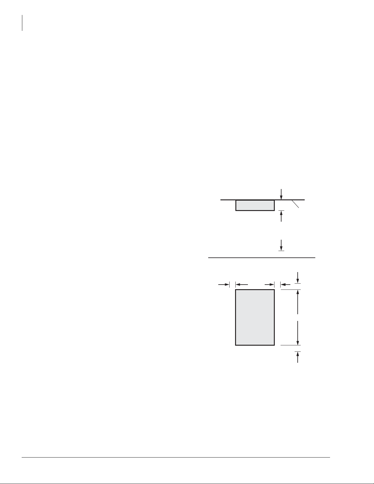
CTX28 Installation
Site Requirements
Site Requirements
This section defines the installation site requirements necessary to ensure a proper operating
environment for the CTX28. Also included are grounding requirements.
Input Power
The system requires an input power source of 115VAC ± 10VAC, 50/60 Hz, 1.5 amps. The AC
outlet is recommended to be dedicated and unswitched. (See “AC Power and Grounding
Requirements” on page 1-4.)
This eliminates interference from branch circuit motor noise or the like, and to prevent accidental
power-off. To avoid accidental power turn-off, Toshiba recommends that you do not use an On/Off
wall switch on this dedicated AC circuit.
For the Strata CTX28, a reserve power source (HPFB-6) may be connected to the system to serve
as a power failure backup (See Step 8 on page 1-18).
Clearance and Location
The minimum clearance requirements for the
Strata CTX28 Base cabinet is shown in
Figure 1-1. Refer to Figure 1-5 on page 1-7 for
CTX28 KSU mounting instructions.
Consider the following conditions when selecting
a location for the KSU(s):
The location must be:
• Dry and clean
• Well ventilated
• Well illuminated
• Easily accessible
The location must not be:
• Subject to extreme heat or cold
• Subject to corrosive fumes, dust, or other
airborne contaminants
• Subject to excessive vibration
• Next to television, radio, office automation, or
high frequency equipment
If reserve power (HPFB-6) is to be installed for
the Strata CTX28, the batteries will require a
well-ventilated location close to the CHSU28A.
Top View
3.5"
Front View
2" 2"
Figure 1-1 CTX28 Base KSU Clearance
12.25"
CTX28
Base KSU
7062
Requirements
Wall
3 Feet
2"
18"
2"
1-2 Strata CTX I&M 06/04
Page 23
CTX28 Installation
Site Requirements
Table 1-1 provides a summary of the electrical and environmental characteristics.
Table 1-1 Summary of Electrical/Environmental Characteristics
CTX28 Primary Power
Input AC (Power Supply Specification)
AC frequency
Power
AC input current
Environmental Specifications
Operating temperature
Operating humidity
Storage temperature
Input DC 15V to use the factory-shipped AC adapter
DC voltage output specification
Standard Telephone Ring Circuit (GMAU and GSTU)
Ring Voltage 180V p-p square wave
Ringing capability 1 REN, 1 circuit - one telephone per circuit
100~240VAC
50/60 Hz
CTX28 - 100 watts maximum
1.5A maximum
32~104° F (0 ~40° C)
20~80% relative humidity without condensation
-4~140° F (-20~60° C)
Power
Power Conver ter
-24VDC (-26.3~-28.3VDC)
+5VDC (+4.5~+5.5VDC)
CTX28 Installation
Strata CTX I&M 06/04 1-3
Page 24
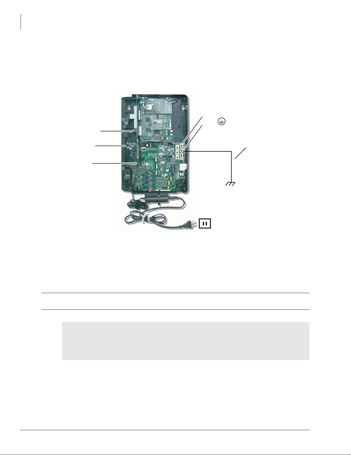
CTX28 Installation
AC Power and Grounding Requirements
AC Power and Grounding Requirements
The CTX28 requires a solid earth ground for proper operation. The AC power cord connects to a
standard AC power outlet. The ground for the CTX28 must originate at the building’s main power
distribution panel and have a solid connection to earth ground. (See Figure 1-2.)
CTX28 Cabinet
TB2
TB3 on GMAU
P10 Wire Connector
to HPFBG Battery Connector
TB1 to HPFB6 FG
(#10 AWG Wire)
AC Adapter Cord
plugs into GMAS
Dealer-supplied wire
(#10 AWG gauge or
larger to pass ground
specification test)
Grounding Rod
or
Electrical Building
Ground (Main Power
Distribution Box)
7126
AC Voltage
90VAC ± 264VAC
AC Current
1.5 amps max.
Figure 1-2 Ground to AC Power Cord
CAUTION! Lack of proper ground may cause improper operation and, in extreme cases,
system failure.
WARNING! Failure to provide a proper ground may be a safety hazard to service
personnel or lead to confusing trouble symptoms, such as noise on the talk
path including GVMU greetings and messages. In extreme cases, system
failure may result because the system is not properly protected from
lightning or power transients.
1-4 Strata CTX I&M 06/04
Page 25
CTX28 Installation
AC Power and Grounding Requirements
AC Power Ground Test
Test the “wire ground” for continuity by either measuring the resistance between the TB3 terminal
(earth ground) on the GMAU and a metal cold water pipe (maximum: 1 ohm), or by using a
commercially available earth ground indicator. If neither procedure is possible, perform the
following earth ground test procedure.
WARNING! Hazardous voltages that may cause death or injury are exposed during the
following test. Use great care when working with AC power line voltage.
³ To perform the earth ground test procedure
1. Obtain a suitable voltmeter, and set it for a possible reading of up to 250VAC.
2. Connect the meter probes between the two main AC voltage terminals (white and black wires)
on the wall outlet. The reading obtained should be between 100~125VAC.
3. Move one of the meter probes to TB3 terminal (green wire ground). Either the same reading or
a reading of zero volts should be obtained.
4. If the reading is zero volts, leave one probe on the ground terminal and move the other probe to
the second voltage terminal.
CAUTION! If a reading of zero volts is obtained on both voltage terminals (white wire to
TB3 wire, black wire to TB3 wire), the outlet is not properly grounded. Omit
Steps 5 and 6, and see following CAUTION!
5. If a reading of zero volts on one terminal, and a reading of 100~125VAC on the other terminal
is obtained, remove both probes from the outlet.
6. Set the meter to the “OHMS/Rx1” scale. Place one probe on the TB3 ground terminal, and the
other probe on the terminal that produced a reading of zero volts. The reading should be less
than one ohm.
CTX28 Installation
CAUTION! If the reading is more than one ohm, then the outlet is not adequately
grounded. If the above tests show the outlet AC voltage is not in range or is
not properly grounded, the condition should be corrected (per Article 250 of
the National Electrical Code) by a qualified electrician before the system is
connected.
Table 1-2 Grounding Wiring Summary
Grounding Requirement From To Description
System connects to earth ground Earth ground TB3 on GMAU
FG of HPFB-6 connect to GMAU HPFB-6 FG Screw TB1 on GMAU
HPFB-6 Ground Feed TB1 on GMAU TB3 on GMAU
GETS connects green ground wire to
GMAU
GETS ground wire TB2 on GMAU
Less than 1 ohm
Strata CTX I&M 06/04 1-5
Page 26
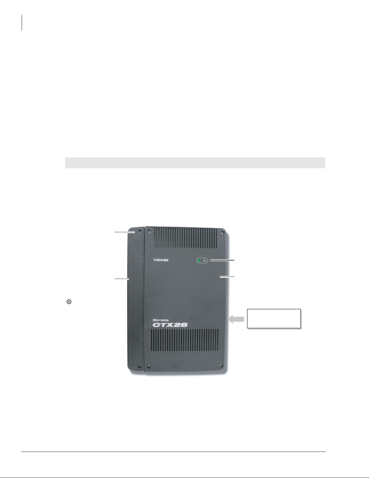
CTX28 Installation
Installing the CTX28 Cabinet
Installing the CTX28 Cabinet
Check the items shipped.
• CHSU28A cabinet
• GCTU1A processor PCB
• AC adapter
• Tie wrap for cable clamp
• Tie wrap for AC adapter
• Velcro strap for AC adapter cord
Step 1: Mount the Cabinet on the Wall
The Base cabinet is designed to be mounted on a wall or other vertical surface.
WARNING! To prevent electrical shock, make sure the power supply switch is turned Off.
³ To mount the Base KSU
1. Make sure the location for the CTX28 meets the minimum clearance requirements specified in
Figure 1-1 on page 1-2.
2. Loosen the screws on the front cover and the side cover of the Base KSU, remove the covers
(see Figure 1-3).
Cover
Screws (6)
Side Cover
=
Six cover screws
to be removed
before mounting
KSU
7125a
Figure 1-3 CTX28 Cabinet Exterior
DC Power LED
Base Cover
Model: CHSU28A
Strata CTX28
Label on edge of
Base KSU
1-6 Strata CTX I&M 06/04
Page 27
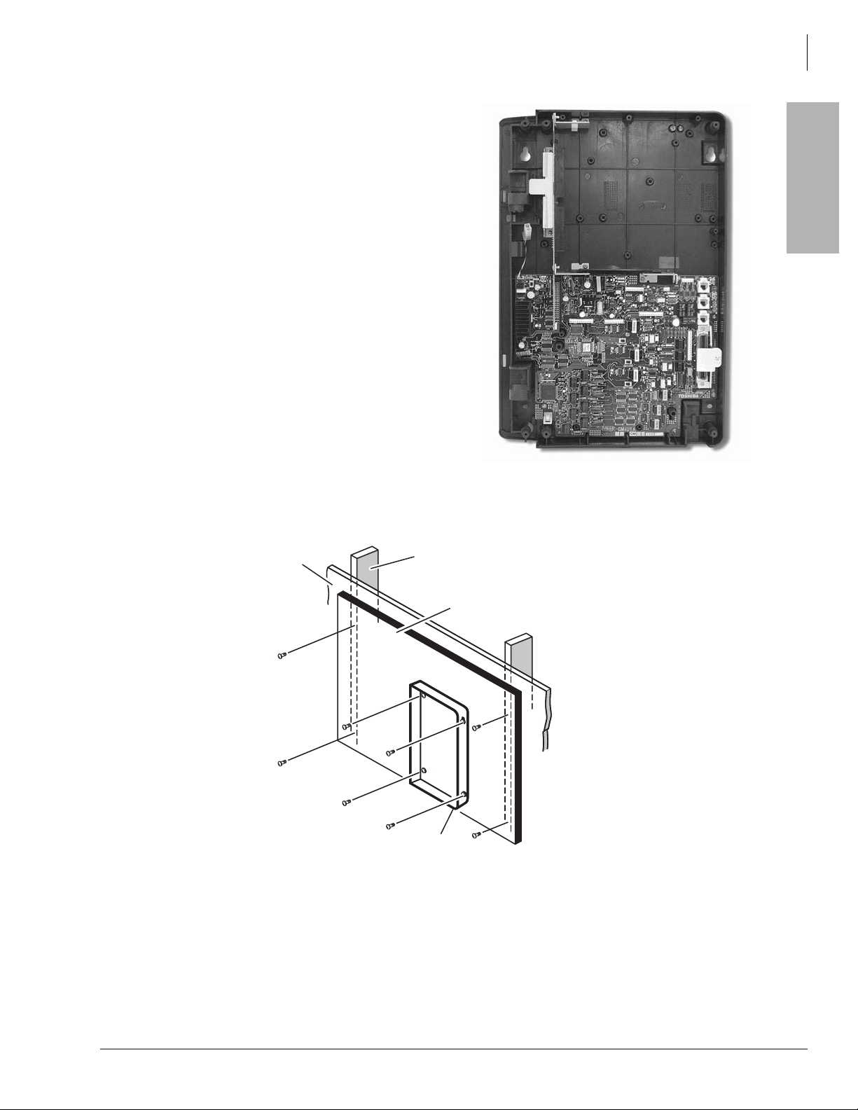
CTX28 Installation
Installing the CTX28 Cabinet
3. Place the Base KSU on the desired
location on the mounting surface and
mark the location of the four screw
holes. See Figures 1-4 and 1-5.
4. Using a hard board between the KSU
and the wall, secure the hard board to
the wall first, making certain that screws
are aligned with studs. See Figure 1-5.
5. Drill holes on these marks and secure
screws approximately two thirds of the
way into the top two holes on the
mounting surface.
6. Hang the unit from the top two screws
and then secure the top screws
completely into the mounting surface.
7. Finish securing the unit to the mounting
surface by completely screwing the
bottom two screws into the wall.
CTX28 Installation
7104
Figure 1-4 CTX28 Base KSU Interior
Plaster
Board
Figure 1-5 KSU Wall Mounting
Stud
Base KSU
Method 2
Hard Board
(1/2 Inch Plywood)
7114
8. Ground system according to “AC Power and Grounding Requirements” on page 1-4.
Strata CTX I&M 06/04 1-7
Page 28
CTX28 Installation
Installing the CTX28 Cabinet
PCB Installation
Overview Instructions
The following is an overview for installing the Printed Circuit Boards (PCBs) into the Strata
CTX28. After reading this section, proceed to the step-by-step instructions for each PCB.
1. Apply proper settings on the GMAU1A (motherboard Figure 1-7).
2. If applicable, set SW6 battery jumper to ON and install the GVMU1A Voice Mail card
(Figures 1-8 and 1-9).
3. Set P601 battery jumper to ON and install the GCTU1A (processor Figures 1-6 and 1-10).
4. If applicable, install the GCDU1A (3 CO, 3 CLID and 8 DKT circuits Figure 1-11).
5. If applicable, install GSTU1A (standard telephone interface Figure 1-12).
6. If applicable, install the GETS1A 100Base-TX I/F PCB (Figure 1-13).
7. If applicable, install the BSIS1A for SMDR (Figure 1-6).
8. If applicable, install HPFB-6 battery/charger (Figure 1-14).
9. Connect wiring (Table 1-14).
10.Connect AC Adaptor to P2 of the CTX28 sub-motherboard (GMAS, Figures 1-15 and 1-16)
and plug the AC Adaptor into AC power.
11.Turn the System ON by sliding the SW1 ON/OFF switch down. The ON/OFF LED located by
STANDBY will turn on (Figure 1-15).
PCB Descriptions
This describes the CTX28 cabinet PCBs (see Tabl e 1 -3 and Figure 1-6.)
Table 1-3 CTX28 (CHSU28) Cabinet circuit cards
Part Title Description
GMAU1A Main Motherboard The GMAU motherboard supports 3 CO lines, 3 CLIDs,
8 Digital Telephones, 1 Standard Telephone. The
GMAS1A Sub-motherboard
GCTU1A Processor Shipped with cabinet.
GVMU1A Voice Mail Circuit Card (Optional) Voice Mail.
GCDU1A
GSTU1A
GETS1A 100BaseT I/F (Optional) Ethernet 100Base T cable.(optional)
BSIS1A RS232C (Optional) RS232-C. Provides 4 serial I/O ports.
HPFB6 External Battery (Optional) Provides backup Reserve power.
CO, CLID, DKT circuit
card
Standard Telephone
Circuit Card
GCTU, GVMU, and AC power adaptor plugs into the
GMAS sub-motherboard dedicated slots.
(Optional) Supports 3 CO lines, 3 CLIDs, 8 Digital
Telephones. The GCDU1A plugs onto the motherboard.
(Optional) Provides 1 Standard Telephone port.
1-8 Strata CTX I&M 06/04
Page 29
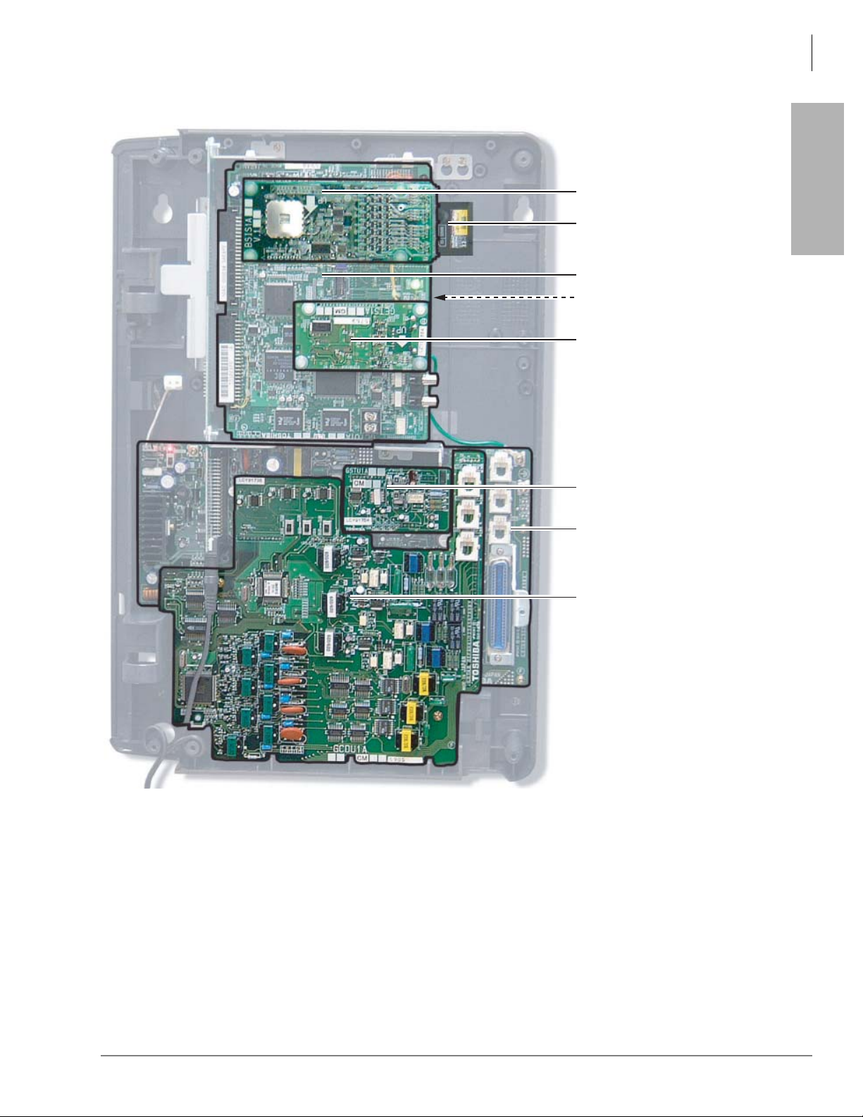
CTX28 Installation
Installing the CTX28 Cabinet
BSIS (RS232-C)
SmartMedia Card
GCTU (Processor)
GVMU (Voice Mail)
installs beneath the GCTU
GETS (100Base TX)
CTX28 Installation
7108
GSTU (Standard Telephone)
GMAU (Main Motherboard)
GCDU
(CO, CLID, DKT)
Figure 1-6 CTX28 Interior with PCBs
Strata CTX I&M 06/04 1-9
Page 30
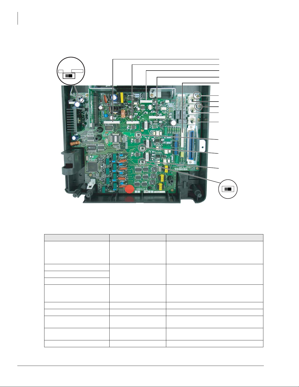
CTX28 Installation
Installing the CTX28 Cabinet
Step 1: Set Jumpers on the GMAU1A (Motherboard)
The GMAU1A (shown in Figure 1-7) supports up to 6 CO lines with Caller ID (CLID).
SW1
STANDBY
ON
SW1
ON/OFF
(Standby)
P5
P6
P8
P7
P4
TB2
CO1
TB3
CO2
CO3
SW400
(3db/0DB)
SW500
(3db/0DB)
7113
Figure 1-7 GMAU PCB
Table 1-4 GMAU Controls, Switches and Indicators
Control/Indicator/Connector Type of Component Description
Power Switch :
SW1 2-position slide switch
[STANDBY] = no DC power supply.
[ON] = DC voltage supplied. [ON] activates the
reserve power from HPFB-6 battery pack.
SW400
2-position slide switch 3dB Pad switchSW500
SW600
Power indicator; when SW1 is [ON], turned on.
CD6 LED
Red both AC power and 3Reserve power. SW1
is [STANDBY], turned off.
TB1 Plate with screw Grounding for HPFB-6 external battery
TB2 Plate with screw Grounding for GETS Ethernet card
TB3 Plate with screw
P1
50-pin Amphenol
connector
Grounding for CTX28 system, connect to earth
ground
DKT, SLT and Power Failure Transfer interface
P3 44-pin DIN connector GMAS interface
SW600
(3db/0DB)
1-10 Strata CTX I&M 06/04
Page 31

CTX28 Installation
Installing the CTX28 Cabinet
Table 1-4 GMAU Controls, Switches and Indicators
Control/Indicator/Connector Type of Component Description
P4 16-pin female connector
P6 10-pin female connector
P7 13-pin female connector
P8 10-pin female connector
P9 6-pin female connector GCDU interface
P10 3-pin connector HPFB-6 external battery interface
P11 3-pin female connector GSTU standard telephone interface
P400
P500 Interface for CO Line circuit (CO2)
P600 Interface for CO Line circuit (CO3)
F1 2.0A Fuse -24VDC Over current protection
Table 1-5 GMAS (Sub-motherboard)
Control/Indicator/Connector Type of Component Description
P1 44-pin DIN male connector GMAU interface
P2 Pin Jack DC-IN (DC15V) jack
J1 44-pin DIN female connector GVMU interface
J2
J3
Modular connector
44-pin DIN female connector GCTU interface
(continued)
GCDU DKT and loop start interfaceP5 13-pin female connector
GSTU standard telephone interface
Interface for CO Line circuit (CO1)
CTX28 Installation
Strata CTX I&M 06/04 1-11
Page 32

CTX28 Installation
Installing the CTX28 Cabinet
Step 2: Install the GVMU1A Voice Mail PCB (optional)
1. In the CTX28 cabinet, remove the two screws and the PCB stopper (Figure 1-8).
2. On the GVMU, set the SW6 battery jumper to ON and set the Greeting language switch
(Figure 1-9). Default language is “English.” See Table 1-6 for other language settings.
3. Turn off system power and if GCTU is installed remove GCTU before installing the GVMU.
4. Install the GVMU into the lower slot of the GMAS (sub-motherboard) (see Figure 1-8).
5. Install the GCTU per Step 3 and turn system power ON.
Note To program GVMU, refer to Strata CTX28 Voice Processing Programming Manual and use
XADM4 Admin software.
³ To re-initialize GVMU to default data after it has been in use (see CAUTION! below)
1. Turn off CTX28 system power and uninstall GCTU and GVMU.
2. Remove the GVMU battery jumper for two minutes.
3. Place the GVMU battery jumper back to the ON position, then install the GVMU and GCTU.
4. Turn system power back on.
CAUTION! Initializing GVMU to default data will erase all Names, Security codes and
Table 1-6 English/French Greetings Settings on the GVMU1A
saved Messages.
Jumper English French English to French French to English
SW2 OFF ON OFF ON
SW3 OFF OFF ON ON
Jumper Admin PC Real Time Debug Monitor
SW4 OFF (default) ON (used for debug information, i.e., log and trace data by TTY.
SW5 Not used.
SW6 Battery Jumper – must be in ON position
GVMU
PCB Stopper
GCTU
GVMU
7252
Figure 1-8 GVMU/GCTU PCB Stopper
7162
1-12 Strata CTX I&M 06/04
Page 33

CTX28 Installation
Installing the CTX28 Cabinet
Status LED
VM Port LEDS
(Ch1 ~ Ch4)
Busy/Idle
Maintenance
Note: For details, see
GVMU Admin PC
Connections later in
this chapter.
RS232C
Jack
SW6 - Battery Jumper
7395
CTX28 Installation
SW2 - Language Jumper
SW3 - Language Jumper
SW4 - Admin PC/Debug Monit
SW5 - Not Used
Figure 1-9 Close Up of PCB Stopper for GCTU and GVMU
Table 1-7 LED Indicators on the GVMU1A
Indication/ State
Power On
(Initialize Sequence*)
Normal
(Busy/Idle)
Ch1 Ch2 Ch3 Ch4 Status
All LEDs turn ON (Red), then all LEDs turn OFF and cycle ON/OFF through all ports
for one to two minutes while initializing and then all LEDs turn off.
OFF OFF OFF OFF
ON = Busy; OFF = Idle
GVMU1A LEDs
Blinking
Failure Blinking Blinking Blinking Blinking OFF
Shut Down ON ON ON ON OFF
Back Up/Restore ON ON ON ON ON
No 1.8V input Voltage
in GVMU
ON OFF OFF ON ON
Not mounted/defective Light flickers and switches from the LED to LED (from Ch1~Ch4) + Status LED
* The initialize sequence operates each time the CTX28 power is cycled off/on or the CTX28 processor is reset
or initialized – GVMU program data remains saved. However, if the GVMU battery jumper is removed, GVMU
program data and saved messages will be erased.
Strata CTX I&M 06/04 1-13
Page 34

CTX28 Installation
Installing the CTX28 Cabinet
Step 3: Install the GCTU1A (Processor)
The GCTU1A is the main processor for the CTX28. It is shipped with the CTX28 Base cabinet.
³ To install the GCTU1A into the CTX28
1. Skip this step if you have installed a Voice Mail PCB and already removed the PCB stopper. If
you have not done this, then in the CTX28 cabinet, remove the two screws and the PCB stopper
(see Figure 1-8).
2. Set the P601 battery jumper to ON (see Figure 1-10) and insert the GCTU1A (shipped with the
cabinet) in the upper slot of the GMAS sub-motherboard (see Figure 1-6). Place it next to the
guide rail of the PCB stopper (see Figure 1-8).
3. Secure the PCB stopper with the original two screws.
4. Insert the SmartMedia card (gold contacts face left, notched corner faces forward and up) into
the SmartMedia slot on the GCTU1A (see Figure 1-6).
OFF ON
P601 Battery
BATT
SmartMedia LED
Heart Beat LED
P903P902
SmartMedia Slot
P2 (for BSIS)
DC Power On/Off LED
P1 (for GETS)
MOH
External Speaker
P901
Control Relay Contact
7264
Figure 1-10 GCTU PCB
1-14 Strata CTX I&M 06/04
Page 35

Table 1-8 GCTU
CTX28 Installation
Installing the CTX28 Cabinet
CTX28 Installation
Control/Indicator/
Connector
P1 60 pin connector GETS Interface
P2 60 pin connector BSIS Interface
P501 SmartMedia house SmartMedia interface
P601 Jumper plug
P801 RCA Jack Paging interface and BGM/MOH interface
P901 2 pin screw terminal Relay contact
P902
P903
CD101 LED Processor operation indication
CD501 LED SmartMedia access indicator
CD908 LED
Type of Component Description
Must always be in the “ON” position to maintain
customer data
44-pin male DIN
connector
44-pin male DIN
connector
CTX28 Back plane connector
CTX28 Back plane connector
Green DC power indicator for CTX28 system. Shown
on front cover (see Figure 1-3).
Strata CTX I&M 06/04 1-15
Page 36

CTX28 Installation
Installing the CTX28 Cabinet
Step 4: Install the GCDU1A (DKT and Loop Start Interface)
The GCDU1A PCB adds an additional 3 CO lines, 3 Caller ID units, and 8 digital telephone
circuits with a single PCB. It attaches to the GMAU1A motherboard. With the GCDU1A installed,
the CTX28 supports up to 16 digital telephones (DKTs), 6 CO lines and 6 Caller ID circuits.
³ To install the GCDU1A
³ Carefully place the GCDU1A pins over the GMAU connectors (see Figure 1-6 and Figure
1-11). Press down on the PCB to secure the pins to the connectors (see Tab l e 1 -9 ).
SW600
SW500
SW400
CO4
CO5
CO6
7260
Figure 1-11 GCDU1A PCB
Table 1-9 GCDU1A Controls, Indicators and Connectors
Control/Indicator/
Connector
SW400
SW600
P4 16-pin male connector
P5 12-pin male connector
P6 9-pin male connector
P9 6-pin male connector
P400
P500 Interface for CO Line circuit (CO5)
P600 Interface for CO Line circuit (CO6)
Type of Component Description
2-position slide switch 3dB Pad switchSW500
GMAU interface
Interface for CO Line circuit (CO4)
Modular connector
1-16 Strata CTX I&M 06/04
Page 37

CTX28 Installation
Installing the CTX28 Cabinet
Step 5: Install the GSTU1A
The GSTU1A provides one additional standard telephone interface.
³ To install the GSTU1A, align the GSTU1A pins over the GMAU1A motherboard and press
down firmly (see Figure 1-6).
7259
Figure 1-12 GSTU1A PCB
Table 1-10 GSTU1A Controls, Indicators, and Connectors
Control/Indicator/Connector Type of Component Description
P7 12-pin male connector
GMAU interfaceP8 9-pin male connector
P11 3-pin male connector
Step 6: Install the GETS1A
CTX28 Installation
The GETS1A supports 100Base TX Ethernet.
³ To install the GETS1A
1. Place option PCB arrow side up over the plastic stand-off with the connectors and stand-off
holes on the GCTU1A. The “UP” arrow should point down. Snap GETS1A securely into place.
2. Attach the FG ring to TB2 on the GMAU1A motherboard with the screw shown in Figures 1-2
and 1-13.
To TB2 On GMAU
FG Green Wire
Ethernet Plug
7261a
Figure 1-13 GETS (100Base TX)
Table 1-11 GETS (100Base TX)
Control/Indicator/Connector Type of Component Description
CD1 LED LAN link indicator
CD2 LED Transmission and receive indicator
P1 60 pin connector GCTU interface
P2 RJ45 Network interface port
Strata CTX I&M 06/04 1-17
Page 38

CTX28 Installation
Installing the CTX28 Cabinet
Step 7: Install the BSIS1A (optional)
The BSIS provides RS-232 serial ports.
³ To install the BSIS1A, align the BSIS1A pins over the GCTU1A and press down firmly (see
Figure 1-6).
Step 8: Install the HPFB-6 (Reserve Power Battery/Charger)
One or two HPFB-6 optional units can be added to the CTX28 to provide reserve power. The
amount of reserve power time depends on the hardware (see Table 1-12). The table below is an
estimate of battery backup time based on the premise that the HPFB-6 unit(s) are fully charged at
the time of AC power failure. This estimated backup time is based on low call traffic, the time
estimates will be reduced by as much as half with extreme heavy traffic volumes.
Table 1-12 CTX28 Reserve Power Duration Estimates
Hardware 1 HPFB-6 2 HPFB-6
3CO/8DKT - No GVMU 1 hr. 40 min. 3 hr. 20 min.
3CO/8DKT - with GVMU 1 hr. 30 min 3 hr.
6CO/16DKT - No GVMU 1 hr. 5 min. 2 hr. 10 min.
6CO/16DKT - with GVMU 1 hr. 2 hr.
1. Place the HPFB-6 directly below the Strata CTX28 KSU. See Figure 1-14 for minimum
clearance requirements. A second HPFB-6 can be installed directly below the unit to supply
backup reserve power.
2. Mark the location of the two screw holes, then drill holes.
3. Screw the two screws two-thirds into the mounting surface.
4. Hang the HPFB-6 on the screws then tighten the screws into the mounting surface.
5. Plug the first HPFB-6 connector into BATT connector P10 on GMAU.
6. Connect a #10 ground AWG wire from the HPFB-6 “FG” screw to the CTX28 screw labeled
“TB1” (Figure 1-2).
Note The CTX28 should be plugged into AC power and the DC power switch should be turned
On when installing the HPFU-6. The HPFU-6 will not start to operate if AC power is not
available during the initial installation.
7. The 24VDC LED on the HPFB-6 should light. If it does not light, press the battery Off switch
with a pencil point or other small-tipped object.
8. Dress and tie-wrap the HPFB-6 cables.
9. To mount a second HPFB-6, repeat Steps 1~4, then plug the second HPFB-6 connector in the
first HPFB-6 and connect an FG wire between each HPFB-6 FG screw.
10. To test the HPFB-6, remove the CTX28 AC plug from the AC outlet. The CTX28 AC LED will
go out, but the CTX28 DC LED remains on. Also the system remains in normal working order
and the HPFB-6 24V LED remains on.
11.If it is desired to turn off the HPFB-6 (after loss of AC power), use a pencil or other sharp
object to press the Battery Off switch.
CAUTION! Once the HPFB-6 is turned Off or unplugged (during AC power loss) it will not
operate again until AC power is restored to the CTX28 KSU.
1-18 Strata CTX I&M 06/04
Page 39

CTX28 Installation
Installing the CTX28 Cabinet
Note The CTX28 KSU does not provide a battery charger, the HPFB-6 contains built-in
batteries and a battery charger; therefore, do not connect any other type of batteries to
the CTX28.
To P10 Connector (see Fig. 1-2)
2“
#10 AWG HPFB
FG Wire to TB1
(see Fig. 1-2)
2“
HPFB Unit:
Reserve Power Battery
and Charger (optional)
From Second HPFB (optional)
7253
2“
2“
CTX28 Installation
Figure 1-14 HPFB-6 Reserve Power Installation
Step 9: Install Wiring
1. Refer to Figure 1-15 for the following steps. Loosen the screw on the Amphenol clamp and
remove the clamp. Plug in the 25-pair Amphenol connector and replace the clamp to hold the
Amphenol connector in place.
2. Connect all other PCB wiring (e.g., modular CO line cords, LAN cable, etc.). Slide the shorter
tie-wrap through the holder. Then fasten wiring to the unit with the tie wrap that comes with the
Base KSU.
3. Connect the end of the AC adapter cable to the GMAS PCB as shown in Figures 1-15 and 1-16.
4. Connect the other end of the GETS (100Base TX) LAN cable to the LAN connected to the
CTX WinAdmin PC.
5. Plug the AC adapter into a power strip connected to an power outlet.
6. Put the On/Standby switch into “On” position. The DC LED should light green. The CTX28 is
now ready to program.
WARNING! Do not smoke near batteries. Avoid creating any electrical sparks near
batteries.
Strata CTX I&M 06/04 1-19
Page 40

CTX28 Installation
Installing the CTX28 Cabinet
BSIS
(4 RS-232C)
P10 (to HPFB
Battery Cord)
TB1 (to HPFB FG)
SW1
STANDBY
ON
SW1
ON/OFF
(Standby)
100 Base TX
Music On Hold
(MOH)
External Speaker
(Paging)
CO, CLID,
DKT
Amphenol
Connector
secured
under clamp
Tie Wrap
(supplied)
Tie Wrap
(supplied)
AC Adapter
7158
Figure 1-15 Standard Unit Wiring (without option units) and AC Adapter
1-20 Strata CTX I&M 06/04
Page 41

CTX28 Installation
Digital Telephone Connection
CTX28 Installation
1
34
Figure 1-16 AC Adapter Wiring Procedure
Digital Telephone Connection
The Strata CTX28 supports any
Toshiba 2000 and 3000-series
digital telephones, including the
new DKT3007-SD telephone
(shown right).
The DKT3007-SD only works on
the CTX28.
2
7257
The DKT3007-SD works just like
the DKT3020-SD and DKT3010SD, except that it has seven
flexible buttons.
The CTX28 supports all
DKT2000 and DKT3000-series
Add-on Modules and DSS
Consoles.
CTX28 supports Handset Offhook Call Announce (OCA), but
not Speaker OCA.
Figure 1-17 DKT3007-SD Telephone
Strata CTX I&M 06/04 1-21
Page 42

CTX28 Installation
Loop Limits
Loop Limits
This section provides the maximum loop lengths for connection of telephones, lines, peripheral
equipment, and power supplies. The following information applies to only the Strata CTX28
system (see Table 1-13). Diagrams that are applicable to all systems, including the CTX28, can be
found in Chapter 10 – MDF PCB Wiring.
Table 1-13 Digital Telephone/DIU/DDSS Console/ADM/Loop Limits
Maximum line length (24 AWG)
1 Pair
feet meters
1 Pair plus
external power
1000 feet
303 meters
Mode
DKT3000-series or DKT2000-series
models, DKT with BVSU or DVSU or
BHEU or HHEU.
DKT with BPCI
DKT with BPCI and BHEU
DDSS3060 or 2060
DDCB3A
BATI, RATI
DKT with 1 ADM
DKT with 2 ADMs
CTX28 KSU or
Battery Backup
CTX28 KSU 1000 303
Battery Backup 695 204
CTX28 KSU 1000 303
Battery Backup 500 151
CTX28 KSU 1000 303
Battery Backup 500 151
CTX28 KSU 1000 303
Battery Backup 675 204
CTX28 KSU 165 50
Battery Backup 500 151
CTX28 KSU 1000 303
Battery Backup 1000 303
CTX28 KSU 675 204
Battery Backup 165 50
CTX28 KSU 500 151
Battery Backup 33 10
1
1. Battery backup applies to instances when the system is being powered by batteries exclusively.
2. Digital cable runs must not have the following:
Cable splits (single or double)
Cable bridges (of any length)
High resistance or faulty cable splices
2
1-22 Strata CTX I&M 06/04
Page 43

CTX28 Installation
CTX28 Secondary Protection
CTX28 Secondary Protection
The following diagram (see Figure 1-18) shows where secondary protectors must be installed for
outside wiring.
Building #1
GMAU
GSTU
GMAU
GCDU
Building #2
Standard
Telephone
DDSS
Console
Digital Telephone
or Cordless Base
MDFB
DDCB
CTX28 Installation
HESB
Digital Telephone
MDFB
GMAU
GDCU
7255
(Earth Ground)
Loop CO Line
Secondary protectors – standard voltage
Secondary protectors – low voltage
Figure 1-18 CTX28 Secondary Protector Diagram
Important! To protect against transient voltages and currents, solid state secondary protectors
must be installed if there is outside wiring. These protectors, which contain fast
semiconductors in addition to fuses, shall comply with the requirements for
secondary protectors for communication circuits, UL 497A. Care must be taken to
ensure that they are very well grounded to a reliable earth ground. Recommended
protectors are available in the fast Series 6 line from ONEAC Corp., Libertyville,
Illinois 60048, (800) 327-8801. Install and test the secondary protectors precisely to
the installation instructions of these manufacturer.
Strata CTX I&M 06/04 1-23
Page 44

CTX28 Installation
MDF Wiring
MDF Wiring
For Registration information refer to “CTX28 FCC/ACTA Registration Numbers” on page 1-1.
TO
NETWORK
T1
R1
Table 1-14 Station Wiring for Amphenol Connector (P1) on GMAU1
Pin No. Signal Pin No. Signal Station
1 VR1 26 VT1 DKT #1
2 VR2 27 VT2 DKT #2
3 VR3 28 VT3 DKT #3
4 VR4 29 VT4 DKT #4
5 VR5 30 VT5 DKT #5
6 VR6 31 VT6 DKT #6
7 VR7 32 VT7 DKT #7
8 VR8 33 VT8 DKT #8
9 VR9 34 VT9 DKT #9
10 VR10 35 VT10 DKT #10
11 VR11 36 VT11 DKT #11
12 VR12 37 VT12 DKT #12
13 VR13 38 VT13 DKT #13
14 VR14 39 VT14 DKT #14
15 VR15 40 VT15 DKT #15
16 VR16 41 VT16 DKT #16
17 (NC) 42 (NC)
18 PF1R 43 PF1T PFT circuit*
19 (NC) 44 (NC)
20 (NC) 45 (NC)
21 (NC) 46 (NC)
22 (NC) 47 (NC)
23 CR1 48 CT1 STU #1
24 (NC) 49 (NC)
25 CR2 50 CT2 STU #2
* Connect a Standard Telephone to PFT pair to provide access to CO Line1 during a power failure.
CO LINE CABLING
T1
R1
R1
R
BK
W
654321
2345
GN
Y
BL
T1
GMAU
GCDU
1
2
3
4
5
6
7
8
9
10
11
12
13
14
15
BRIDGING
CLIPS
1
2
3
4
5
6
7
8
9
10
11
12
13
14
15
48
49
50
66M150 SPLIT BLOCK
7262
48
49
50
Figure 1-19 MDF Wiring to CO Lines (GMAU and GCDU)
MODULAR
CORD
NETWORK JACK: RJ14C
FIC: 02LS2
R2
5
R1
4
T1
3
T2
2
GMAU
GCDU
PIN-OUT
3456
1-6
2
1
CO1~6
MODULAR
JACKS
1-24 Strata CTX I&M 06/04
Page 45

CTX28 Installation
GVMU Administration PC Connections
GVMU Administration PC Connections
6-wire Modular Cord - telephone
cross-pinned type (modular jack locking
tabs on the same side of the cord).
Toshiba PPTC or PPTC9
connectors to PC COM port
PC with GVMU XADM Software
RS232C Jack
Strata CTX28 Serial Port Modular Pins
1
RD
2
TD
3
DSR
4
DTR
5
CD
6
SG
(Data from GVMU)
(Data to GVMU)
(Data Set Ready from GVMU)
(Data Terminal Ready to GVMU)
(Carrier Detect from GVMU)
(CTX/Terminal Signal Ground)
Strata CTX28
GVMU
CTX28 Installation
7407
GVMU RJ11
(Six-pin jack)
Figure 1-20 GVMU Serial Port Interface Connection
Dealer Supplied
CO LineCO Line
Toshiba PPTC25-MDM
connector to Modem
Remote GVMU
PC using
XADM software
Modem
RS-232 Cable
Telephone
Network
Figure 1-21 GVMU PC Modem Interface Connection
RS232C Maintenance
Ext.
Modem
Strata CTX28
Jack
GVMU
3-Pair Modular Cord - telephone
cross-pinned type (modular jack
locking tabs on the same side of
the cord).
7406
Strata CTX I&M 06/04 1-25
Page 46

CTX28 Installation
GVMU Administration PC Connections
Connect to PC 9-pin
COMX Port (DTE)
(female)
23451
PPTC-9
RD
2
3
6
6789
4
1
5
TD
DSR
DTR
DCD
SG
6
5
4
3
2
1
6
SG
DCD
5
DTR
4
DSR
3
TD
2
RD
1
GVMU
RS232C
Maintenance Jack
DB9 Pinout
(front view)
(male)
234567208
7405
Connect to External
Modem (DTE)
DB25
Pinout
(front view)
Figure 1-22 Serial Port Adaptors Pin Numbers
PPTC25-MDM
RD
2
TD
3
DSR
20
DTR
6
DCD
8
SG
7
Jumper
Pin 4-5
Modular Jack Pinout
(front view)
6
6
5
4
3
2
1
SG
DCD
5
DTR
4
DSR
3
TD
2
RD
1
Modular Jack Pinout
(front view)
GVMU
RS232C
Maintenance Jack
1-26 Strata CTX I&M 06/04
Page 47

Strata CTX Configuration 2
This chapter contains information and worksheets to help configure the Strata CTX100-S,
CTX100 and CTX670 hardware components. A system overview of the Strata CTX100-S,
CTX100 and Strata CTX670 hardware components and the maximum station and line capacities
available with the system processor is provided.
Worksheets follow this information to aid in determining the actual cabinets and interface PCBs
needed for particular proposals and how these PCBs should be placed in Strata CTX cabinet slots.
(Worksheets begin on page 2-22.)
Strata CTX100-S/CTX100 Overview
The Strata CTX100-S/CTX100 systems are
compact systems, yet they provide large system
features (see Figure 2-1 and Table 2 -1 ). It is
designed for wall mounting and occupies very
little space.
They are designed for wall mounting and
occupy very little space.
The CTX100 processor (ACTU2A) comes with
32 ports (licensed) and can grow to 112 ports
by adding 4-port licenses.
The CTX100-S processor (ACTU2A-S) comes
with 16 ports (licensed) and can grow to 32
ports by adding two eight-port licenses. Then, it
can grow to 112 ports with four-port licenses.
Figure 2-1 CTX100-S /CTX100
Note The Strata CTX100-S and CTX100
system capacities depend on the licenses
stored on the system processor and the hardware described in this chapter. See “CTX100-S/
CTX100 License Control” on page 2-4.
Base Expansion
Base/Expansion Cabinets
5976
Configuration
Strata CTX
Important! The Strata CTX100-S uses the same hardware and configuration as the Strata
CTX100, with a few exceptions. Whenever the CTX100 is mentioned in this book, it
applies to both the CTX100-S and CTX100, unless specified otherwise.
Each ACTU2 basic processor can be configured with a one or two cabinet system. A single (Base)
cabinet system supports a combination of up to 64 Central Office (CO) lines and stations, while a
two cabinet system (Base and Expansion) can support up to 112 CO lines and stations.
System line and station capacity is expanded by adding CO line and station Printed Circuit Boards
(PCBs) and port licenses into its universal slot architecture.
Strata CTX I&M 06/04 2-1
Page 48

Strata CTX Configuration
CTX100-S and CTX100 Processors
The CTX100 easily connects to outside public and private telephone lines. All of the telephones
(stations) tied to the system can have direct access to each other, as well as to the public and
private network. All lines, stations, and options are tied together through the cabinets.
Table 2-1 CTX100-S / CTX100 Cabinet Specifications
Cabinet
Base Cabinet (CHSUB112A) 19.4 lbs. 14.6 in. 11.9 in. 10.2 in.
Base + Expansion Cabinet (CHSUE112A) 34.6 lbs. 14.6 in. 19.9 in. 10.2 in.
1. Weight includes the processor PCB in the Base Cabinet and four universal PCBs in each cabinet.
Weight
1
CTX100-S and CTX100 Processors
Each system operates with one processor PCB (ACTU2A-S for CTX100-S, ACTU2A for
CTX100) that installs in a dedicated slot of the Base Cabinet. The processors incorporate the
following hardware features
CPU/Memory
Either processor PCB uses a high-speed, 32-bit, RISC processor, Dynamic Random Access
Memory (DRAM) working memory, Static Random Access Memory (SRAM) with lithium battery
for memory back-up, and flash program memory.
Height Width Depth
Large Scale Integrated (LSI) Circuits
The processors each have LSI circuits that support the following:
• 16 DTMF receiver hardware processor are built into the ACTU2. Five or more DTMF receivers
requires appropriate licenses. See “CTX100-S/CTX100 License Control” on page 2-4.
• 16 Busy Tone (BT) detector circuits for Auto Busy Redial (ABR) are built into the ACTU2.
• 64 built-in conference circuits (see Table 2-7 on page 2-12 for more information).
• Built-in, adjustable, digital volume PAD technology enables audio volume to be adjusted in
eight steps to compensate for conference and/or CO line network losses.
Memory Protection Battery
If commercial AC power is lost or if a system is moved or stored without power, either processor
has an on-board battery that protects data and the customer’s programmed configuration from
memory loss. This information will be maintained in a powerless system for at least six years.
Relay Control Interface
An on-board terminal strip provides an interface to a normally open relay contact which can be
programmed to control a Night Bell, door lock or to mute BGM during an external page.
External Page Interface
A 600 ohm RCA jack is built into the processor to interface with a Toshiba External Amplified
Speaker (HESB) or a customer-supplied page amplifier and speaker(s) for external paging, night
ring over external page, and external BGM applications.
2-2 Strata CTX I&M 06/04
Page 49

Strata CTX Configuration
CTX100 Cabinet Slots
Music-on-hold/Background Music Interface
A 600-ohm RCA jack and volume controls are built into the processor to interface with Music-onhold and/or Background Music (BGM) sources (one of the jacks is for future use). With the
CTX100, you can have up to 15 MOH/BGM source interfaces by adding:
• Up to two BIOU PCBs, each provides three MOH/BGM input sources
• An RSTU PCB that provides up to eight MOH/BGM input sources
• An ASTU PCB provides one alternate BGM source
SmartMedia Memory
Each processor has an on-board SmartMediaTM memory card slot. A SmartMedia flash memory
card can be inserted into the slot to backup and restore customer program data. It also makes it
easy to upload operating system data for software upgrades and is used for maintenance functions.
CTX100 Processor Optional Subassemblies
Optional subassemblies can be attached to the ACTU2A-S or ACTU2A processors to provide
additional features. The subassemblies are:
• AMDS (Modem) – Provides a 33.6Kbps/V.34 modem for point-to-point local or remote
connection to the CTX WinAdmin
• BSIS (Serial Port Interface) – Provides up to two RS-232 interface ports for SMDR interface
to Call Accounting devices, SMDI or Toshiba Proprietary interface to Voice Mail devices, and
two future applications.
TM
administration PC.
CTX100 Cabinet Slots
Base Cabinet
The Base Cabinet has one dedicated slot used for the system processor PCB and four universal
slots (S101~S104), that can accommodate station, line or option PCBs. It also houses a power
supply that is packaged with the cabinet.
Configuration
Strata CTX
Expansion Cabinets
One expansion cabinet provides four universal PCB slots (S105~S108) that can accommodate
station, line or option PCBs. It also houses a power supply that is packaged with the cabinet.
Strata CTX I&M 06/04 2-3
Page 50

Strata CTX Configuration
CTX100-S/CTX100 License Control
CTX100-S/CTX100 License Control
The system size and feature capability is controlled using a software License Key Code. This key
code is obtained from Toshiba Internet FYI during the ordering process and is installed onto the
system processor via Strata CTX WinAdmin. Processor license codes activate system hardware
capacities in the following increments.
• The first 16 line/station ports on the CTX100-S do not require a license. The upgrade from 16
to 24 ports and from 24 to 32 ports requires the eight port upgrade LIC100S-8 PORTS license.
Each additional set of 4 line/station ports requires the four port upgrade LIC100-4 PORTS
license.
• The first 32 line/station ports on the CTX100 do not require a license. Each additional set of
four line/station ports requires one LIC100-4 PORTS license (maximum of 112 ports).
• The ACTU2A-S and ACTU2 processors each provide 16 DTMF built-in receiver hardware
circuits and 16 ABR circuits. The first four DTMF circuits and all ABR circuits do not require
a license. Each additional set of four DTMF receiver circuits requires one LIC100-4DTMF
license (maximum of 16 DTMF circuits).
Note DTMF tone receiver circuits are required for standard telephones, Voice Mail DTMF
integration, Tie, DID and DNIS line service.
• The optional RS-232 serial port interface (BSIS) provides two circuits to interface with SMDI
or Toshiba Proprietary Voice Mail integration, Call Accounting SMDR, and two for future
applications. The first circuit does not require a license, but circuits two through four each
require one LIC100-SER PORT license.
Licensed Software Options
Some software options are activated with license codes. The following software options require a
license:
• Each CTX system (node) in a Strata Net QSIG Network (ISDN or IP) requires one LIC100QSIG NET license. A maximum of four serial network nodes are allowed in any one serial
chain in the network topology.
• The built-in LAN interface for all CTI Open Architecture applications. Each individual CTI
Open Architecture application requires one LIC100-CSTA AP license (maximum nine).
2-4 Strata CTX I&M 06/04
Page 51

Strata CTX670 Overview
The Strata CTX670 system provides sophisticated
telecommunication features in a modular system
designed for growth. Its universal slot architecture
enables you to select the combination of Central Office
(CO) lines, stations, and peripheral options that best suit
your needs.
The CTX670 basic BCTU processor can be configured
for smaller systems as a one or two cabinet system with a
capacity of up to 192 CO lines and stations combined. It
can expand to support up to seven cabinets with a
capacity of up to 672 CO lines and stations combined
with the BCTU/BEXU processors (see Figure 2-2).
System line and station capacity is expanded by adding
processor expansion Printed Circuit Boards (PCBs),
cabinets and line/station PCBs.
The CTX670 easily connects to outside public and
private telephone lines. All of the telephones (stations)
tied to the system can have direct access to each other as
well as to the public and private network.
Strata CTX Configuration
Strata CTX670 Overview
Configuration
Strata CTX
Note The Strata CTX670 system capacities depend on
the licenses stored on the system processor and
the hardware described in this chapter. See
“CTX670 License Control” on page 2-7.
Figure 2-2 CTX 670 Base/
Expansion Cabinets
The Base Cabinet and optional Expansion Cabinets are
the building blocks of the system. Each system has a Base Cabinet, and can have from one to six
Expansion Cabinets. All lines, stations, and options are tied together through the cabinets.
The overall weight and dimensions of the CTX670 cabinets are shown in Table 2-2.
Table 2-2 CTX670 Cabinet Specifications
Cabinet Weight Height Width Depth
Base Cabinet (CHSUB672A) 31 lbs. 11.625 in. 26.5 in. 10.3 in.
Expansion Cabinet (CHSUE672A) 29 lbs. 9.75 in. 26.5 in. 10.3 in.
CTX670 Processor PCBs
The system operates with the BCTU only or the BCTU and BEXU processor PCBs install in
dedicated slots of the Base Cabinet. The BCTU and BEXU processor incorporates the following
on-board hardware features:
CPU/Memory
5398
The CTX670 uses a high-speed, 32-bit, Reduced Instruction Set Computing (RISC) processor,
Dynamic Random Access Memory (DRAM) working memory, Static Random Access Memory
(SRAM) with lithium battery for back-up memory, and flash program memory.
Strata CTX I&M 06/04 2-5
Page 52

Strata CTX Configuration
CTX670 Processor PCBs
Large-scale Integrated (LSI) circuits
The processor has LSI circuits that support the following:
• BCTU provides 16 built-in DTMF receivers; 32 available using the BCTU and BEXU. For five
or more DTMF receivers, appropriate licenses are required. See “CTX670 License Control” on
page 2-7.
• BCTU provides 16 built-in Busy Tone (BT) detectors for Auto Busy Redial (ABR); 32
available using the BCTU and BEXU.
• BCTU provides 64 built-in conference circuits; up to 96 conference circuits are available using
the BCTU and BEXU. (See Table 2-7 on page 2-12 for more information).
• Built-in, adjustable, digital volume PAD technology enables audio volume to be adjusted in
eight steps to compensate for conference and/or CO line network losses.
Memory Protection Battery
If commercial AC power is lost or if a system is moved or stored without power, the processor has
an internal battery that protects data and the customer’s programmed configuration from memory
loss. This information will be maintained in a powerless system for at least six years.
Music-on-hold/Background Music Interface
An RCA jack and volume control are built into the processor to interface with a Music-on-hold
and/ or Background Music source. With the CTX670, you can have up to 15 MOH/BGM sources
by adding:
• Up to two BIOU PCBs, each provides three MOH/BGM input sources.
• An RSTU PCB that provides up to eight MOH/BGM input sources.
• MOH/BGM source volume adjustment is controlled by software programming.
SmartMedia Memory
The processor has an on-board SmartMedia card slot. A SmartMedia flash memory card can be
inserted to backup and restore customer program data. It also makes it easy to upload operating
system data for software upgrades and is used for maintenance functions.
Network Interface
The processor has an on-board Ethernet 10base-T Ethernet circuit for connection to Open
Architecture Computer Telephony Interface (CTI) applications. This provides extensive call
control and telephone support for CTI applications. The Ethernet Network Interface Card (NIC)
port also enables connection to the following:
• CTX Attendant Console
• ACD server
• Local and Remote CTX WinAdmin PC
• Soft Key Control of Voice Mail features
2-6 Strata CTX I&M 06/04
Page 53

Strata CTX Configuration
CTX670 License Control
CTX670 Processor PCB Subassemblies
Subassemblies can be added to the BCTU processor PCB to provide additional features. The
subassemblies are:
• AMDS (Modem) – Provides a 33.6Kbps/V.34 modem for point-to-point local or remote
connection to the CTX WinAdmin
• BSIS interface PCB which attaches to the BCTU to provide up to four RS-232 interface ports
for SMDR Call Accounting and SMDI or Toshiba Proprietary Voice Mail interface.
See Table 2-3 on page 2-9 for the number of cabinets and universal PCB slots for the Basic and
Expanded systems.
TM
administration PC.
CTX670 License Control
The system size and feature capability is controlled using a software License Key Code. This key
code is obtained from the Toshiba Internet FYI site during the ordering process and is installed
onto the system processor via Strata CTX WinAdmin. Processor license codes activate system
hardware capacities in the following increments.
• The first 64 line/station ports do not require a license. Each additional set of four line/station
ports requires one LIC670-4PORTS license (maximum of 672 ports).
• The on-board DTMF receiver circuit provides up to 32 DTMF receiver hardware circuits. The
first four DTMF circuits do not require a license. Each additional set of four DTMF receiver
circuits requires one LIC670-4DTMF license (max. total of 32 DTMF circuits).
Note DTMF tone receiver circuits are required for standard telephones, Voice Mail DTMF
integration, Tie, DID and DNIS line service.
• The optional RS-232 serial port interface (BSIS) provides two circuits to interface with Voice
Mail SMDI or Toshiba Proprietary Voice Mail integration, Call Accounting SMDR, and two
for future applications. The first circuit does not require a license, but circuits two through four
each require one LIC670-SER PORT license.
Configuration
Strata CTX
Licensed Software Options
Some software options are activated with license codes. The following software options require a
license:
• Each CTX system (node) in a Strata Net QSIG Network requires one LIC670-QSIG NET
license. A maximum of four serial network nodes are allowed in any one serial chain in the
network topology.
• Each individual CTI Open Architecture application requires one LIC670-CSTA AP license
(maximum nine).
Strata CTX I&M 06/04 2-7
Page 54

Strata CTX Configuration
CTX670 Cabinet Slots
CTX670 Cabinet Slots
Base Cabinet
The Base Cabinet has two dedicated slots used for the system processor PCBs and eight universal
slots, labeled “S101~S108,” that can accommodate station, CO line or option PCBs (see Figure
2-3). It also houses a power supply.
B101 B102 S101 S102 S103
S104 S105 S106 S107
S108
B101 B102 S101 S102 S103 S104 S105 S106 S107 S108
BEXU
BCTU
Figure 2-3 Strata CTX670 Base Cabinet Interior
Expansion Cabinets
One to six Expansion Cabinets can be added to increase the system station and CO line capacity.
Each expansion cabinet provides 10 slots (S_01~S_10). Figure 2-4 shows an Expansion Cabinet.
Refer to the following section for cabinet slot and station/line capacities. Tables 2-4 and 2-5 show
the number of stations and CO lines allowed when additional cabinets and PCBs are used.
DC OUT
-24V1
-24V2
BATT
+
-24V3
-
-24V4
POW
+5V
AC IN
-5V
P.F.
POWER
RESET
ON
EXP
BASE
OFF
FG
5002
6965
DC OUT
CABINET NO.
2
34567
S_01 S_02 S_03 S_04 S_05
S_06 S_07 S_08 S_09 S_10
S_01 S_02 S_03 S_04 S_05 S_06 S_07 S_08 S_09 S_10
DC OUT
-27V1
-27V1
-27V2
-27V2
AC IN
BATT
+
-27V3
+
-27V3
-
-
-27V4
-27V4
POW
POW
+5V
AC IN
+5V
AC IN
-5V
-5V
P.F.
P.F.
POWER
RESET
POWER
RESET
ON
ON
EXP
EXP
BASE
BASE
OFF
OFF
FG
FG
5002
5002
5003
Figure 2-4 Strata CTX670 Expansion Cabinet Interior
2-8 Strata CTX I&M 06/04
Page 55

CTX670 Remote Expansion Cabinet
A CTX670 Expansion Cabinet can be located up to three kilometers from its Base Cabinet.
Remote Expansion Cabinets are enabled by the RRCU PCB. One RRCU connects to up to two
ribbon-type Data Cables and applies the inter-cabinet signal to a multi-mode fiber-optic pair. One
fiber pair can support one or two expansion cabinets in one remote location using one RRCU in the
Base Cabinet and another in the Remote Expansion Cabinet.
The CTX670 Base Cabinet supports up to six Remote Expansion Cabinets (at least one RRCU
PCB is required for each remote location).
Strata CTX Configuration
CTX670 Remote Expansion Cabinet
Remote cabinets support the BIOU for external Page Zones, Night Bell, etc., and all CO line and
trunk interface PCBs. Network clock synchronization can only be derived from digital trunks
installed in the Base Cabinet (Master) location.
System Capacities
This section contains Strata CTX100 and CTX670 capacities for stations and peripherals, CO
lines, station buttons and system features. All tables apply to both systems unless otherwise noted.
Important! The maximum capacities listed for the CTX100 in Tables 2-3~2-7 are based on an
expanded CTX100 (Base + Expansion cabinet).
Table 2-3 Cabinet and Slot Capacities
Cabinets/Slots/Ports CTX100
Cabinets
Universal slots
Maximum capacity of ports
(lines + stations)
Table 2-4 Station/Peripherals System Capacities
Stations
Add-on modules (DADM3120,
DADM3020) per Base Cabinet
Add-on modules (DADM3020) per
Expansion Cabinet
CTX Attendant consoles
DKT3000- and 2000-series DKTs
IPT telephones
IPT telephones with DADM3120
Cordless Telephones
(DKT2004-CT, DKT2104-CT,
DKT2204-CT, DKT2304-CT)
Door locks
Door phone control boxes (DDCB)
1
1
2
1
1
Base & Expansion
30 DKTs with 1 ADM
23 DKTs with 2 ADMs
31 DKTs with 1 ADM
24 DKTs with 2 ADMs
(40 Base Cabinet)
(40/Expan. Cab.)
CTX670
Basic Processor
BCTU
1 or 2 1 to 2 1 to 7
4 or 8 8 or 18 8 to 68
112 192 672
CTX100
224
72/system
64 per cabinet
72 per system
26 per cabinet
26 per system
72 152 552
4510
238
CTX670
Basic Processor
BCTU
55 DKTs with 1 ADM
43 DKTs with 2 ADMs
57 DKTs with 1 ADM
45 DKTs with 2 ADMs
152/system
(72 Base Cabinet)
(80/Expan. Cab.)
128 Base
160 Expansion
160 System
58 per cabinet
58 per system
CTX670
Expanded Processor
BCTU + BEXU
CTX670
Expanded Processor
BCTU + BEXU
55 DKTs with 1 ADM
43 DKTs with 2 ADMs
57 DKTs with 1 ADM
45 DKTs with 2 ADMs
552/system
(72 Base Cabinet)
(80/Expan. Cab.)
128 Base
160 Expansion
560 System
200 per cabinet
200 per system
Configuration
Strata CTX
Strata CTX I&M 06/04 2-9
Page 56

Strata CTX Configuration
System Capacities
Table 2-4 Station/Peripherals System Capacities
Stations
CTX100
Base & Expansion
Door phones
DSS consoles (DDSS)
ISDN BRI station circuits TE-1 and TA
(2B+D per circuit)
Off-premise stations
BPCI used for TAPI only: per cabinet
1
Total Stations (Digital/Analog/ISDN
BRI B channel combined)
Standard stations
Calls existing at the same time
1. Limit is based on cabinet Power Factor (PF).
2. Based on the maximum allowed flexible buttons.
(continued)
CTX670
Basic Processor
BCTU
6924
3516
12 28 96
64 144 544
35 66 66
72 160 560
64 144 544
56 96 366
CTX670
Expanded Processor
BCTU + BEXU
Table 2-5 Line Capacities and Universal PCB Slots
Lines
CO lines – loop start
(analog - 8 lines/slot)
CO lines – ground start
(analog - 4 lines/slot)
DID lines (analog - 4 lines/slot)
Tie lines (analog - 4 lines/slot)
VoIP lines (4 lines/slot)
T1 lines (DS-1)
ISDN BRI B channel lines
ISDN PRI B channel lines
Strata Net over IP Channels
1
2
3
4
5
Total lines (Analog, T1, ISDN BRI and
PRI B channels combined)
Channel Groups
Number of groups w/ GCO Line
buttons
1. Capacity is limited by FCC, Part 15, ElectroMagnetic Compatibility (EMC) restrictions.
2. T1 lines can be loop start, ground start, Tie or DID (maximum 24 lines per unit, any type or combination).
3. BRI lines provide CO line services, including Caller ID, DID and Direct Inward Lines (DIL).
4. PRI lines provide CO line services, including QSIG Networking, Calling Party Number/Name, DID, Tie, POTS, FX and DIT.
5. Strata Net over IP channels provides Strata Net functionality.
CTX100
Base & Expansion
64 96 264
32 72 264
32 72 264
32 72 264
82020
64 96 264
64 96 256
48 96 264
48 96 264
64 96 264
32 48 128
32 50 128
CTX670
Basic
Processor
BCTU
CTX670
Expanded
Processor
BCTU + BEXU
2-10 Strata CTX I&M 06/04
Page 57

Table 2-6 Station Buttons
Strata CTX Configuration
System Capacities
Station Buttons per System
Call Forward, Personal CF Buttons
CO Line Buttons
Group CO Line Buttons
Pooled CO Line Buttons
CO Group and Pooled Line Buttons
Station Loop Buttons
Door Unlock Buttons
Flexible Telephone Buttons
Line Buttons in use at the same time
Message Waiting Registration (DNs with MW)
Multiple Appearances of DNs on Telephones
Night Transfer Buttons
One Touch Buttons
Primary Directory Numbers [PDNs] per system
Phantom Directory Numbers [PhDNs] per system
[PhDNs] with Message Waiting Indication LED
ISDN DNs
CTX100 Base &
Expansion
CTX670
Basic Processor
BCTU
CTX670 Expanded
Processor
BCTU + BEXU
72 160 560
64 96 264
64 96 264
32 50 128
64 96 264
81550
4816
1600 3500 12000
1440 3200 3200
130 230 800
2000 4000 12000
32 64 128
800 1750 6000
72 160 560
288 640 2240
18 38 128
96
(8 DNs/station)
224
(8 DNs/station)
768
(8 DNs/station)
Configuration
Strata CTX
Strata CTX I&M 06/04 2-11
Page 58

Strata CTX Configuration
System Capacities
Table 2-7 System Feature Capacities
Features
Pilot DNs
Advisory LCD Messages (Set on a Telephone)
Advisory LCD Messages Lists (per System)
Attendant Groups
Call Accounting SMDR Interface
1
Call Forward, System CF Patterns
Call Park Orbits (General)
Call Park Orbits (Individual)
Caller ID/ANI/CNIS Numbers stored (Call History
records)
CO Line Groups - Incoming Line Groups (ILG)
CO Line Groups - Outgoing Line Groups (OLG)
Outgoing Line Groups (OLG) Members per
system
(Trunks + ISDN Line Service Index)
Conference Circuits
Conferencing (three-parties simultaneously)
Conferencing (eight-parties simultaneously)
2
2
Conference Party types (up to 8 total lines +
stations)
Two-CO Line Conferencing – simultaneously2
(Two party only, no telephone or VM port)
Conference/Line Volume Adjustment (PAD)
Groups
DID Numbers for Calling Number ID/system
DNIS/DID Network Routing Numbers
DNIS/DID Numbers
DTMF Receivers
3
E911 Groups
Emergency Call Groups
Hunt Groups (Serial/Circular/Distributed
combined)
Hunt Group Size (DNs per group)
Hunt Group Stations (per system)
ISDN DNs
ISDN Line Service Indexes
Multiple Call Ring Group
Night Bell Control Relay
Night Transfer Control Relay
4
4
Off-hook Call Announce Handsets (simultaneous)
CTX100 Base &
Expansion
CTX670
Basic Processor
BCTU
CTX670 Expanded
Processor
BCTU + BEXU
100 200 256
1 11
10 10 10
1 11
1 11
4 10 32
14 32 64
56 96 336
Up to 100/station Up to 100/station Up to 100/station
Up to 660/system Up to 1000/system Up to 2000/system
32 50 128
32 50 128
96 144 392
64 64 96
20 21 21
8 812
6 lines max.
8 stations max.
6 lines max.
8 stations max.
6 lines max.
8 stations max.
32 48 132
6 10 32
225 500 1000
200 400 1000
450 1000 2000
16 16 32
8 88
8 88
90 200 640
72 160 560
360 800 2800
96 224 768
32 48 128
16 32 64
1 11
11 1
20 21 31
2-12 Strata CTX I&M 06/04
Page 59

Strata CTX Configuration
System Capacities
Table 2-7 System Feature Capacities
Features
Off-hook Call Announce to Telephone Speakers
Page Mute External BGM Control Relay
Page Zone Relays
4
Page Groups (Phones with or without External Zones)
Paging – (Group Page – simultaneous stations paged)
Pickup Groups
Ring Tones (External Call Ring Tones for DKTs)
Ring Tones (Internal Call Ring Tones for DKTs)
Speed Dial - Station SD numbers per system
Speed Dial - System SD numbers per system
Stratagy DK Voice Mail Systems per system
Tenants
Destination Restriction Level (DRL) Classes
Verified Account Codes
Voice Mail SMDI Interface
1. SMDI and SMDR require BSIS serial port interface.
2. Conference circuits are used dynamically, so the maximum number of simultaneous conferences is affected by the number of
conference members in each conference. The total number of members in simultaneous conferences cannot exceed the total
number of conference circuits. Each conference can have up to eight members.
3. DTMF receivers are required for standard touch tone telephones, voice mail integration, Tie, DID and DISA lines.
4. An option BIOU is required for up to four zone page relays and four control relays on the CTX100 and CTX670. One control
relay is provided on board the CTX100 processor.
5. Speaker OCA capacity is determined by 2B channel slot availability and power supply. Requires BVSU option in telephone.
Speaker OCA is not available on IPT1020-SD telephones.
6. Up to 100 Station SD numbers, allocated in increments of 10, can be programmed per station.
1
(continued)
4
6
CTX100 Base &
5
Expansion
CTX670
Basic Processor
BCTU
CTX670 Expanded
Processor
BCTU + BEXU
72 112 352
11 1
8 88
4 816
72 120 120
5 10 32
4 44
1 11
1080 2400 5600
800 800 800
1 11
1 11
16 16 16
135 300 1000
1 11
Configuration
Strata CTX
Strata CTX I&M 06/04 2-13
Page 60

Strata CTX Configuration
Universal Slot PCBs
Universal Slot PCBs
Universal Printed Circuit Boards (PCBs) installed in the Strata CTX100 or CTX670 cabinets
provide interfaces for stations, lines, and peripherals. Each PCB measures 7.5 x 5.5 inches (190 x
140 mm) and mounts in the slot with a 44-pin backplane connector. PCB external connections to
station equipment are made to the Main Distribution Frame (MDF) using industry-standard
connectors.
Station, Line and Option PCBs
The PCBs are categorized as station, CO line or option PCBs (see Tabl e s 2 - 8~2-10). Feature
subassemblies that plug onto a universal slot PCB, such as the Standard Telephone Interface
Subassembly (RSTS), are listed below the associated PCB.
Table 2-8 Station PCBs
Digital Telephone Interface Unit (ADKU) (CTX100 only)
Provides eight circuits for 3000 and/or 2000-series
digital telephones.
Standard Telephone Interface Unit (ASTU) (CTX100 only)
Provides two standard telephone circuits. Maximum
number of ringers per circuit is three
Digital Telephone Interface Unit (BDKU)
Provides eight circuits for 3000 and/or 2000-series
digital telephones (BDKU) + eight more with BDKS
(optional).
Digital Telephone Interface Subassembly (BDKS)
Provides eight additional circuits for 3000 and/or 2000series digital telephones. Attaches to BDKU. One per
BDKU. Do not use BDKS for Speaker OCA telephones,
except in slot 103 of the CTX100.
Digital Telephone Interface Unit (PDKU2)
Provides 8 digital telephone circuits. (2000-series
phones only. Do not use the PDKU for 3000-series
digital telephones. With 3000-series DKTs, the LCD
display is only 16 characters wide and the
will not work.
Spdial button
Interface Options: Provides the same interface options as
the BDKU (see below), but does not support BDKS.
Compatible only with CTX100.
Interface Options:
Standard telephones (no message waiting)
Other single-line devices
Alternate BGM source
Fax machines
Voice mail devices
Interface Options: Digital telephones (with or without
BHEU, BPCI, BVSU, DADMs, or digital cordless
telephone). Supports BDKS.
Stand-alone digital cordless telephone
DDSS console
BATI
DDCB
Supports large LCD (DKT3014) features.
Interface Options: Same as BDKU. Not compatible with
ADKU or PDKU.
Interface Options: Digital telephones (with or without
BHEU or HHEU, DVSU, DADMs, or digital cordless
telephone)
Stand-alone digital cordless telephone
DDSS console
DDCB
Does not support DKT3014-SDL features.
2-14 Strata CTX I&M 06/04
Page 61

Strata CTX Configuration
Universal Slot PCBs
Table 2-8 Station PCBs
Digital Telephone Interface Unit (BWDKU1A)
Provides 8 or 16 digital telephone circuits. Compatible
with Strata CTX and Strata DK. Jumper plugs on the
PCB determine the number of DKT circuits and CTX or
DK compatibility. It does not need a Ferrite Core. It has
one protector for every two circuits. The BWDKU1A is
similar to BDKU/BDKS, except DKT wiring is all 1 pair.
Internet Protocol Telephone (IPT) Interface Unit (BIPU-M1A, BIPU-M2A)
Provides 16 IPT telephone circuits
One 100Base-TX RJ45 port
Built-in Digital Signal Processor (DSP) (BIPS1A-16)
One RS-232 maintenance port
Network Address Translation (NAT) compatible for
remote IP telephones (BIPU-M2A)
Enhanced version of MEGACO+ for Voice over IP
MEGACO+ mobility for Mobility Communications
System (MCS) Roaming (BIPU-M2A)
Digital/Standard Telephone Interface Unit (RDSU)
Without RSTS, provides:
Two standard telephone/
Four digital telephone circuits (2000-series phones
only).
With RSTS, provides:
Four standard telephone/
Four digital telephone circuits (2000-series phones
only).
Standard Telephone Interface Unit (BSTU, RSTU3)
Provides eight standard telephone circuits. Stutter dial
tone is provided for Message Waiting audible indication.
Standard Telephone Subassembly (RSTS)
Attaches to RDSU. Provides two additional standard
telephone circuits. One maximum per RDSU.
-48 Volt Supply Internal Option (R48S)
Attaches to BSTU, RSTU and RDSU
48VDC circuit for up to eight standard telephone circuits.
Stratagy DK
Provides two, four, six, or eight VM ports.
All of the above Stratagy DK systems use eight station
ports of Strata CTX capacity.
(continued)
Interface Options: Digital telephones (with or without
BHEU or HHEU, DVSU, DADMs, or digital cordless
telephone)
Stand-alone digital cordless telephone
DDSS console
DDCB
Interface Options: LAN, Virtual Private Network (VPN)
Internet, VPN WAN, Intranet.
Interface Options:
Digital – same as PDKU.
Standard – same as RSTU (standard Message Waiting
not available)
Interface Options:
Standard telephones
Voice mail ports
Off-premises stations
Other similar devices
Alternate BGM source
Auto Attendant digital announcer
Message Waiting lamp
Fax machines
ACD announcer
Interface Options: Same as RSTU, except no Message
Waiting lamp.
Interface Options: Optionally interfaces to the RSTU and
RDSU to extend loop length of standard telephones from
600 ohms to 1200 ohms. Required for OPS operation.
Configuration
Strata CTX
Strata CTX I&M 06/04 2-15
Page 62

Strata CTX Configuration
Universal Slot PCBs
Table 2-9 CO Line PCBs
Strata Net Over VoIP Interface Unit (BIPU-Q1A)
Provides 16 IP QSIG channels
One 100Base-TX RJ45 port
One RS-232 maintenance port
QSIG over IP standard protocol (ECMA-336)
Voice coding G.711/G.729A
Built-in Digital Signal Processor (DSP) (BIPS1A-16)
NAT compatible
Internet Protocol (IP) Interface Unit (BVPU)
Provides four VoIP Circuits as E&M Tie lines
One 10Base-T port
One RS-232 maintenance port
H.323 standard for Voice over Internet Protocol
(VoIP)
Caller ID Interface Unit (RCIU2)
Provides four Caller ID circuits.
With RCIS: eight circuits.
Caller ID Interface Subassembly (RCIS)
Attaches to the RCIU2.
Direct Inward Dialing Interface Unit (RDDU)
Provides four DID circuits. Interface Options:
Enhanced 911 CAMA Trunk Interface Unit (RMCU/RCMS)
E911 CAMA circuits. Provides up to four CAMA trunk
circuits. The RMCU/RCMS eliminates the need for
connection of adjunct terminal adapter equipment to
E911 CAMA trunks.
Requires one or two RCMS PCBs for two or four
CAMA lines respectively.
CAMA Trunk Subassembly (RCMS)
RCMS attaches to RMCU. Provides two E911 CAMA
circuits.
Up to two RCMSs per RMCU for four CAMA lines
max. (One RCMS comes packaged with the RMCU.)
Ground/Loop Start Interface CO Line Interface Unit (RGLU2, RGLU3)
Provides four ground or loop start line circuits. Each
can be individually set for ground or loop start
operation.
ISDN S/T-type Basic Rate Interface Unit (RBSU)
Two ISDN BRI S/T point circuits (NT or TE). Each
circuit is 2B+1D. (Host for the RBSS.)
Basic Rate Interface Subassembly (RBSS)
Attaches to RBSU. One RBSS subassembly per
RBSU.
Two ISDN BRI, S point circuits (2B+D each).
Interface Options: LAN, Virtual Private Network (VPN)
Internet, VPN WAN, Intranet.
Interface Options: LAN, Internet, WAN.
Interface Options:
Provides Caller ID LCD display for analog loop or
ground start lines with Caller ID. Requires: RCOU,
RCOS, RGLU2, RGLU3 or PCOU. Not compatible with
T1.
Same as RCIU2.
DID analog lines.
E911 analog CAMA trunks.
Same as RMCU.
Interface Options:
Analog loop or ground start analog lines.
Interface Options: Network and/or station side.
Interface Options: Station side only.
2-16 Strata CTX I&M 06/04
Page 63

Strata CTX Configuration
Universal Slot PCBs
Table 2-9 CO Line PCBs
ISDN U-type Basic Rate Interface Unit (RBUU)
Provides two ISDN BRI, U point circuits (2B+D each).
Host for the RBUS.
Basic Rate Interface Subassembly (RBUS)
Attaches to RBUU. One RBUS subassembly per
RBUU.
Two ISDN BRI, U point circuits (2B+D each)
subassembly for the RBUU.
ISDN Primary Rate Interface Unit (BPTU1 or RPTU2)
Provides (1~8B + D), (1~16B + D), or (1~23B + D)
channels (lines), depends on system programming.
BPTU or RPTU2 is required for QSIG Networking.
Loop Start CO Line Interface Unit (RCOU)
Provides four CO analog loop start line circuits.
With RCOS, provides eight CO analog loop start line
circuits.
Loop Start CO Line Interface Subassembly (RCOS)
Provides four additional Loop Start CO lines. One
RCOS subassembly per RCOU.
T1/DS-1 Interface Unit (RDTU2)
Provides T1 (DS1) Interface: 1~8, 1~16, or 1~24
channels (lines), depends on system programming.
Remote Expansion Cabinet Unit (RRCU)
Supports two CTX670 remote cabinets. 62.5 mµ,
multi-mode fiber.
Tie Line Unit (REMU2)
Provides four analog Tie line circuits. Interface Options:
(continued)
Interface Options: Network and/or station side.
Network side requires a dealer-supplied NT1 interface.
Interface Options: Network and/or station side.
Interface Options:
ISDN PRI
POTS
FX
Tie (senderized)
Tie (cut through)
OUTWATS (intra-LATA)
OUTWATS (inter-LATA)
InWATS
QSIG
Interface Options:
CO analog loop start lines
Same as RCOU.
Interface Options:
T1
Loop start lines
Ground start lines
Tie lines (wink or immediate)
DID/DOD lines (wink or immediate)
Remote cabinet not supported by main system reserve
power.
E&M Tie lines
Two- or four-wire transmission
Type I signaling
Type II signaling
Immediate start
Wink start
Configuration
Strata CTX
Table 2-10 Option PCBs
Option Interface Unit (BIOU) Interface Options:
Provides Paging output (600 ohm and three-watt amp),
four zone paging relays, three MOH interfaces and four
control relays (Night Transfer and BGM mute).
Strata CTX I&M 06/04 2-17
Page 64

Strata CTX Configuration
Functional Block Diagrams
Functional Block Diagrams
The Functional Block Diagrams show the PCBs and interface connectors used for connecting the
station.
SMDR
Call Accounting
SMDI or Toshiba Proprietary
Integration
Toshiba Proprietary Soft Key LCD Link
Internet
25 Pair
Remote CTX
WinAdmin PC
ACD
(CSTA)
Stratagy ES
Voice Mail
Local CTX
WinAdmin
Amplified Page Output (3 Watts)
Music Source: External Zone Page
Background Music
Door Lock Control Relay
Night Bell Control Relay
External Zone Page Relays (4 Zones)
MOH/BGM Jack
+Volume Control
Hub
or
LAN
MOH/BGM
RCA Jacks
Up to Four Programmable Serial (RS-232)
Port Modular Jacks Available
Processor PCB
ACTU
1
BSIS
(Optional)
1
AMDS
Remote Maintenance
Modem
RJ45
Ethernet
Interface
Relay Contact (Programmable)
RCA Jack (600 ohm Page Output)
DTMF/ABR
Receivers
License
Interface PCB
BIOU
(one or two per system)
Relay Contacts
MOH/BGM
Volume Controls
1
Conference
SW with PAD
Smart Media
Maintenance
and
Customer
2
Database
ASTU
Virtual slot 09
Data and Speech Highway
External Page Amplifier (600 ohm Output)
BGM Mute Control Relay
Night Control Relay
Main Distribution
Frame (MDF)
APSU112
Cabinet
Power Supply
1
ABCS
Battery Charger
12V
Battery
12V
Battery
(2 or 4 Batteries)
ABTC - 3m Cable
1
Notes
Music Source 1: Background Music
and/or Music-on-hold
Music Source 2: Background Music
and/or Music-on-hold
Music Source 3: Background Music
and/or Music-on-hold
1. Optional.
2. License Control.
On this page, all equipment, except Stratagy ES,
connected to the system processor PCBs and
BIOU PCB is customer-supplied.
6752
Figure 2-5 CTX100 System Processor and Option Interface PCBs
2-18 Strata CTX I&M 06/04
Page 65

SMDR
Call Accounting
Strata CTX Configuration
Up to Four Programmable Serial (RS-232)
Port Modular Jacks Available
Processor PCB
BCTU
Functional Block Diagrams
Remote CTX
WinAdmin PC
ACD
(CSTA)
Stratagy ES
Voice Mail
SMDI and Stratagy ES Integration
Toshiba Proprietary Soft Key LCD Link
Internet
Local CTX
WinAdmin
Amplified Page Output (3 Watts)
Music Source: External Zone Page
Background Music
Door Lock Control Relay
Night Bell Control Relay
External Zone Page Relays (4 Zones)
MOH/BGM Jack
+Volume Control
25 Pair
Hub
or
LAN
MOH/BGM
RCA Jacks
BSIS
(Optional)
AMDS1 Remote
Maintenance Modem
DTMF/ABR
Receivers( Built-In )
Memory Time Switch
RJ45
Ethernet
Interface
Processor PCB
BEXU
Memory Time Switch
Interface PCB
BIOU
Relay Contacts, Page Output
MOH/BGM
Volume Controls
BPSU672
Battery Charger
2
License
3
Cabinet
Power Supply
Conference
SW with PAD
Smart Media
Maintenance
and
Customer
Database
DTMF/ABR
Receivers
( Built-In )
12V
Battery
12V
Battery
(2 or 4 Batteries)
Configuration
Strata CTX
Data and Speech Highway
External Page Amplifier (600 ohm Output)
BGM Mute Control Relay
Night Control Relay
Music Source 1: Background Music
and/or Music-on-hold
Music Source 2: Background Music
and/or Music-on-hold
Music Source 3: Background Music
and/or Music-on-hold
Main Distribution
Frame (MDF)
Notes
1. Optional.
2. Optional. See description of License Control
earlier in this chapter.
3. Optional one or two per system.
On this page, all equipment, except Stratagy ES,
connected to the system processor PCBs and
BIOU PCB is customer-supplied.
6942
Figure 2-6 CTX670 System Processor and Optional Interface PCBs
Strata CTX I&M 06/04 2-19
Page 66

Strata CTX Configuration
Functional Block Diagrams
Page ScrollMode Feature
Msg
Spdial
Vol
Mic Redial
Cnf/Trn
Spkr
Hold
IP Telephone
Remote
Location(s)
Remote Location(s)
With or without
VPN Router
or Server
Remote
Node(s)
CTX / DK
BVPU
CTX Expansion
CTX
BIPU-Q1A
IP Network
Cabinets
IP Network
Optical Fiber Cable
IP Network
3 km/(1.86 mi.)
With or without
VPN Router
or Server
100Base-TX
10Base-T
RRCU
Remote Cabinet Interface Card
BIPU-M2A
BIPU-Q2A
Strata Net QSIG Over IP Unit
BVPU
Voice Over IP Unit (4 Circuits)
Page ScrollMode Feature
Msg
Spdial
Vol
Mic Redial
Cnf/Trn
Spkr
Hold
Digital
Telephone
Demarcation
•
Central Office
•
Centrex
•
•
PBX
•
•
Common Carrier
•
•
Other Telephone System
•
•
E911 Public Safety Answer
•
Point (PSAP)
•
Priviate Networking Lines
MCK
EXTender
Remote Location(s)
Network
Point
4
IP Network
(Two 4-Wire Modular Jacks)
(Two 4-Wire Modular Jacks)
(Two 4-Wire Modular Jacks)
(Two 4-Wire Modular Jacks)
MDF
1
(Two 4-Wire Modular Jacks)
(Two 4-Wire Modular Jacks)
Secondary Protectors
2
(REMU, Four 8-Wire Modular Jacks)
25-pair Amphenol
TOSHIBA NDTU Cable
DB15
Channel
Service
Unit (CSU)
CAMA Line (2-wire Modular Jacks)
CAMA Line (2-wire Modular Jacks)
Toshiba RPRI-CBL-KIT
Channel
Service
2
Unit (CSU)
MCK
Gateway
2
8-wire Modular Jacks
BDKU/BDKS or PDKU
(CTX100 & CTX670) or
(CTX100 only)
ADKU
4 Caller ID Circuits
RCIU2
4 Caller ID Circuits
RCIS
RCOU3
4 Loop Start Co Lines (Analog)
RCOS
(Optional PCB on RCOU Only):
4 Loop Start CO Lines (Analog)
RGLU2, RGLU3
4 Loop or Ground Start CO Lines (Analog)
4 DID CO Lines (Analog)
RDDU
REMU
4 E&M Tie Lines (Analog)
RDTU2 or RDTU3?
• 2T1 / DS1(24 Channels / Lines)
• Loop Start, Ground Start, Tie, DID
PLL Synchronization Circuits
Trunk Circuits for E911
RMCU
RCMS 2 Trunk Circuits
RCMS 2 Trunk Circuits
BPTU1 or RPTU1 or 2
ISDN PRI (23B+1D channels)
Digital Voice/Data
QSIG networks (RPTU2)
4
Data and Speech Highway
1. RCIU2/RCIS tip/ring cross
connected to RCOU, RCOS, or
RGLU tip/ring at MDF.
2. Customer-supplied equipment.
3. U, S, T, R, are ISDN reference
model termination points.
4. RPTU2 is required for QSIG
Networking.
NT1 per circuit
3
U
3
U
3
U
2
8-wire Modular Jacks
3
T
8-wire Modular Jacks
8-wire Modular Jacks
ISDN BRI (S/T)
RBSU
2 Circuits (TE)
Voice/Data (2B+D)
ISDN BRI (U)
RBUU
2 Circuits (NT-1?)
Voice/Data (2B+D)
RBUS
ISDN BRI (U)
2 Circuits (NT-1)
Voice/Data (2B+D)
6739
Figure 2-7 CTX100 and CTX670 CO Line Side Functional Block Diagram
2-20 Strata CTX I&M 06/04
Page 67

BWDKU
8 or 16 Digital Telephone Circuits
BDKU
8 Digital Telephone Circuits and
BDKU/BDKS
16 Digital Telephone Circuits
ADKU
8 Digital Telephone Circuits (max).
(CTX100 only)
4
PDKU2
8 Digital Telephone Circuits
4
RDSU
4 Digital Telephone Circuits
2 Standard Telephone Circuits
RSTS
(Option PCB)
2 Standard
Telephone
Circuits
iES32
4~32 Voice Mail Circuits (Programmable)
IVP8
Data and Speech Highway
2~8 Voice Mail Circuits (Programmable)
ASTU (CTX100 only)
2 Standard Telephone Circuits
RSTU3/BSTU
8 Standard
Telephone Circuits
RBSU
2B+1D/Circuit
(2-NT Circuits)
RBUU
2B+1D/Circuit
(2-LT Circuits)
2
R48S
(Option PCB,
RDSU/RSTU3
Only) -48 Volt
Loop Supply
R48S
(Option PCB,
RDSU/RSTU3
Only) -48 Volt
Loop Supply
RBSS
2B+1D/Circuit
(2-NT Circuits)
RBUS
2B+1D/Circuit
(2-LT Circuits)
Digital Telephone (DKT)
and Add-on Module
BATI
Digital Telephone
with BPCI-DI
4
1 Pair Modular Cord
Transformer
VM Ports
Modem
1-pair Modular Cords
DPFT
Power Failure
Transfer Unit
Secondary
Protector
3
S
3
S
3
U
3
U
R
TA
Cordless DKT
Page ScrollMode Feature
Msg
Spdial
Vol
Mic Redial
Cnf/Trn
Spkr
Hold
Connects audio path to Attd Console
4
Handset
Page ScrollMode Feature
Msg
Spdial
Vol
Mic Redial
Cnf/Trn
Spkr
Hold
RS-232 Cable
Music
on-hold
source
(up to 8)
Stratagy ES
Voice Mail
TAPI PC
Page ScrollMode Feature
Msg
Spdial
Vol
Mic Redial
Cnf/Trn
Spkr
Hold
1
Page ScrollMode Feature
Msg
Spdial
Vol
Mic Redial
Cnf/Trn
Spkr
Hold
Digital
Telephone
Standard
Telephone
RS-232 Cables
Auto Attendant
(Dealer supplied)
1
Fax
Power Failure
Standard Telephone (8 max.)
3
1
ISDN
Telephone
(TE-1, S-Type)
1
ISDN
Telephone
(TE-1, U-Type)
Strata CTX Configuration
Functional Block Diagrams
Digital Single Line
Telephone (DKT)
DDCB
MDFB
Door Phones and
Lock Controls
Digital Telephone
with DSS Console
1
PC
1
Off-premises Station
COM Port
1
PC
PC with
Video Card
(TE-1, U-Type)
Configuration
Strata CTX
6966
1. Customer-supplied equipment.
2. RSTU2 or above is required for standard telephone message
waiting lamp.
Modular Jacks
Main Distribution Frame (MDF)
3. U, S, T, R are ISDN reference model termination points.
4. PDKU and RDSU should only be used for 2000-series digital
telephones. They do not support all of the 3000-series digital telephone
features, including LCD. The PDKU also does not support BPCI, BATI
and the CTX Attendant Console.
Figure 2-8 CTX100 and CTX670 Station Side Functional Block Diagram
Strata CTX I&M 06/04 2-21
Page 68

Strata CTX Configuration
Worksheet Description
Worksheet Description
These configuration worksheets cover Strata CTX telephones, PCBs and cabinets; they do not
cover other peripheral equipment requirements.
Knowledge of all customer telephone requirements is needed to complete the worksheets. These
include all telephone sets, CO line types and Strata CTX system feature options for the main
location (with the Strata CTX Base Cabinet) and each remote location. A set of worksheets for the
main system location and a separate set of worksheets for each remote location must be completed.
CTX670 Remote Cabinet Configuration Considerations
Several items must be considered when configuring a CTX670 system with Remote Cabinets.
(CTX100 systems do not support remote cabinet configurations).
1. Each location must be configured independently. Separate worksheets are needed for each
location to break down the line, trunk and service circuits by locations. Use the rules provided
in this chapter to determine the required quantities of PCBs.
2. Estimate the number of cabinets according to normal configuration worksheets.
3. Account for RRCU PCBs at each remote location (see Table 2-52 on page 2-38 in Worksheet
6). An RRCU PCB can support up to two Expansion Cabinets at one remote location. For
example, 18 PCBs at one remote location would require two Expansion Cabinets and one
RRCU card for the remote location.
4. If necessary, adjust the number of cabinets required. The maximum number of Expansion
Cabinets per system is six. The maximum number of remote locations is also six. The
maximum number of cabinets supported by one fiber connection is two.
5. Determine the total number of RRCU PCBs required at all remote locations (see Table 2-52 on
page 2-38 in Worksheet 6). Add the same number of RRCU cards to the configuration of the
Base Cabinet.
6. Validate the configuration. A valid configuration answers “yes” to the following questions.
• Do all cabinets (local and remote) comply with power limitations? The RRCU has a power
factor of 4.0. See Table 2-58 on page 2-43 in Worksheet 7.
• Are there six or fewer remote locations?
• Are there six or fewer RRCU cards in the Base Cabinet?
7. Order one cabinet cover (BCTC) and cable mesh shield (B50MT) for each remote location.
8. Digital Trunks – A Remote Cabinet can support all PCBs that can be installed in a local
Expansion Cabinet, including digital trunk cards. However, the system cannot derive network
clock synchronization from a digital trunk installed in a remote cabinet. This requires a digital
trunk installed in the Base Cabinet or in a local Expansion Cabinet connected to the Base by a
standard ribbon cable. For each Remote Cabinet location, local trunks may be required for
correct 911 service.
Component Worksheets
Fill in Worksheets 1~8 for each location to determine system cabinet and PCB requirements for:
Customer Name _____________________ Location Description_____________________
Main Location _______________ Remote Location 1___ 2___ 3___ 4___ 5___ 6___
2-22 Strata CTX I&M 06/04
Page 69

Strata CTX Configuration
Worksheet 1: Toshiba DKT and IP Telephones
Worksheet 1: Toshiba DKT and IP Telephones
Main Location _______________ Remote Location 1___ 2____ 3____ 4____ 5____ 6____
Item# Digital Telephone Equipment Required for Cabinet Number __________ Qty
DT01 DKT3010-S - 10 button Digital Speakerphone (gray)
DT02 DKT3010-S (W) - 10 button Digital Speakerphone (white)
DT03 DKT3010-SD - 10 button Digital Speakerphone with LCD (gray)
DT04 DKT3010-SD (W) - 10 button Digital Speakerphone with LCD (white)
DT05 DKT3020-S - 20 button Digital Speakerphone (gray)
DT06 DKT3020-S (W) - 20 button Digital Speakerphone (white)
DT07 DKT3020-SD - 20 button Digital Speakerphone with LCD (gray)
DT08 DKT3020-SD (W) - 20 button Digital Speakerphone with LCD (white)
DT09 DKT3014-SDL - 14 button Digital with large LCD (gray)
DT10 DKT3014-SDL - 14 button Digital with large LCD (white)
DT11 DDSS3060 - 60 button Digital Direct station Select Console (gray)
DT12 DDSS3060 - 60 (W) button Digital Direct station Select Console (white)
DT13 IPT1020-SD - 20 button IP Telephone (gray)
DT14 DKT2010-S -10 button Digital Speakerphone (gray)
DT15 DKT2010-S (W) -10 button Digital Speakerphone (white)
DT16 DKT2010-SD -10 button Digital Speakerphone with LCD (gray)
DT17 DKT2010-SD (W) -10 button Digital Speakerphone with LCD (white)
DT18 DKT2020-S -20 button Digital Speakerphone (gray)
DT19 DKT2020-S (W) -20 button Digital Speakerphone (white)
DT20 DKT2020-SD -20 button Digital Speakerphone with LCD (gray)
DT21 DKT2020-SD (W) -20 button Digital Speakerphone with LCD (white)
DT22 DKT2020-FDSP -20 button Digital Full-Duplex Speakerphone with LCD (gray)
DT23 DDSS2060- 60 button Digital Direct Station Select Console (gray)
DT24 DDSS2060 (W) -60 button Digital Direct Station Select Console (white)
DT25 DDCB - Digital Door Phone Control Box (supports 3 MDFB Door phones)
DT26 Pre-wired Digital Telephone Ports (allocates spare, hot wired digital ports)
DT27 DKT2204-CT - Digital Cordless Phone (digital spread spectrum - sharing por t with DKT)
DT28 DKT2204-CT - Digital Cordless Phone (digital spread spectrum - stand alone)
DT29 DKT2304-CT - Digital Cordless Phone (digital narrow band sharing port with DKT)
DT30 DKT2304-CT - Digital Cordless Phone (digital narrow band - stand alone)
DT31 Total Digital ports required (Add DT01 Qty. ~ DT29 Qty.)
DT32 Total BDKU, BWDKU or BDKU/BDKS or ADKU PCBs/Slots required (DT30, Qty./8 or DT30 Qty./16)
DT33 Total RDSU PCBs/Slots required to add 4 DKT/2 SLT Devices
DT34 Total RDSU/RSTS PCBs/Slots required to add 4 DKT/4 SLT Equipment
Item IP Telephone Qty
IPT01 IPT1020-SD
IPT02 Total BIPU-M2A PCBs/slots required (IPT01 quantity/16)
1. Do not count shared ports into the Total (DT20) BWDKU or BDKU/BDKS ports required.
2. Round up these totals to the nearest whole number.
1
1
2
Configuration
Strata CTX
Important! The maximum number of DKTs per cabinet is 80. This is a power factor limitation
(see Worksheet 7)
Strata CTX I&M 06/04 2-23
Page 70

Strata CTX Configuration
Worksheet 2: Standard Telephone, Stratagy DK, IVP8
Miscellaneous Digital Telephone Equipment (See Table 2-52)
DT34 RFDM - External Microphone for DKT2020-FDSP Full Duplex Digital Speakerphone
DT35 MDFB - Door Phone connected to Digital Door Phone Control Box (requires 1DDCB output)
DT36 Door Lock connected to Digital Door Phone Control Box (requires 1DDCB output)
DT37 BVSU - Interface for Digital Telephones that require Speaker OCA (DKT3000 and DKT2000)
DT38 BPCI - PC/TAPI Interface for digital telephone (gray) (DKT3000)
DT39 Secondary Protectors for any Digital station devices located off-premise.
DT40 BHEU - Telephone Headset Interface (DKT2000 and DKT3000)
DT41 DADM3020 - 20-button Add-on module (gray)
DT42 DADM3020(w) - 20-button Add-on module (white)
DT43 DADM2020 -20 button Digital Add-on Module (gray)
DT44 DADM2020 (W) -20 button Digital Add-on Module (white)
DT45 DADM3120 - 20 button IP or DKT Add-on module (gray)
Worksheet 2: Standard Telephone, Stratagy DK,
IVP8
Main Location _______________ Remote Location 1___ 2___ 3___ 4____5___ 6____
Item# Dealer Supplied Standard Telephone (SLT) Equipment Required Qty
ST1 Standard Tone-Dial Telephone
ST3 External Modem and/or Fax Devices
ST4 External Voice Mail Ports to support Stratagy or other VM (not for Stratagy DK)
ST5 Other Devices, not listed, requiring standard telephone circuit interface
ST6 Alternate BGM Source connected to Std.Tel. port (allocates ASTU, BSTU, RSTU ports)
ST7 Pre-wired Standard Telephone ports (to allocate spare, hot wired, standard tel. ports)
ST8 Total ASTU, BSTU, RSTU PCBs/Slots required (ST1~ST9, QTY/8)*
ST9 Total RDSU PCBs/Slots required to add 4 DKT/2 SLT Devices
ST10 Total RDSU/RSTS PCBs/Slots required to add 4 DKT/4 SLT Equipment
Miscellaneous Standard Telephone (SLT) Equipment Required
ST11 R48S PCB for up to 8 Standard Telephone Off Premise Station (OPS) circuits
ST12 Secondary Protector for Standard telephone equipment located off premise
ST13 DPFT, Power Failure Transfer Unit for up to 8 standard telephone/loop start lines
Stratagy DK or IVP8 Equipment Required
ST14
Each Stratagy Voice Mail PCB provides up to 8 Voice Mail ports and uses 8 ports of system capacity. No
other PCBs are required to interface with Stratagy DK or IVP8. (One allowed per CTX system.)
2-24 Strata CTX I&M 06/04
Page 71

Worksheet 3: CO Line
Main Location _______________ Remote Location 1___ 2___ 3___ 4____5___ 6____
Strata CTX Configuration
Worksheet 3: CO Line
Item # CO Line Type Required
CO1 Analog Loop Start CO Lines with RCOU /4= RCOU 1 Slot/RCOU =
Analog Loop Start CO Lines with
CO2
RCOU/RCOS
Analog Ground Start CO Lines with
CO3
RGLU
CO4 Caller ID Line interface with RCIU /4= RCIU 1 Slot/RCIU =
CO5 Caller ID Line interface with RCIU/RCIS /8= RCIU/RCIS 1 Slot/RCIU/IS =
CO6 BVPU VoIP Circuits
CO7 Analog Tie Lines with REMU /4= REMU 1 Slot/REMU =
CO8 Analog DID Lines with RDDU /4= RDDU 1 Slot/RDDU =
CO9 T1 Digital Lines with RDTU2 /24= RDTU2 2 Slots/RDTU2 =
CO10 T1 Digital Lines with RDTU2 /16= RDTU2 1 Slot/RDTU2 =
CO11 T1 Digital Lines with RDTU2 /8= RDTU2 1 Slots/RDTU2 =
CO12 IP with BIPU-Q1A /8= BIPU-Q1A 1 Slot/BIPU-Q1A =
CO13 IP with BIPU-Q1A /16= BIPU-Q1A 1 Slot/BIPU-Q1A =
CO14 ISDN and/or QSIG with RPTU or BPTU /23 RPTU2 1 Slot/RPTU2 =
CO15 ISDN and/or QSIG with RPTU or BPTU /16 RPTU2 1 Slot/RPTU2 =
CO16 ISDN and/or QSIG with RPTU or BPTU /8 RPTU2 1 Slot/RPTU2 =
CO17 ISDN BRI Circuit
ISDN BRI Circuits
CO18
RBUS
ISDN BRI Circuits
CO19
RBSU
ISDN BRI Circuits
CO20
RBSU/RBSS
E911 CAMA Circuits (RMCS/RCMS=2
CO21
circuits, add another RCMS for 4
circuits
CO22 Total Slots required for line PCBs
2
3
, U-type with RBUU
1
, U-type with RBUU/
1
, S/T-type with
1
, S/T-type with
Line
Qty
PCB
/X=
/8= RCOU/RCOS 1 Slot/RCOU/RCOS =
/4= RGLU 1 Slot/RGLU =
/4= BVPU 1 Slot/BVPU =
/2= RBUU 1 Slot/RBUU
/4= RBUU/RBUS 1 Slot/RBUU/US =
/2= RBSU 1 Slot/RBSU =
/4= RBSU/RBSS 1 Slot/RBSU/RBSS =
/4= RMCU/RCMS 1 Slot/RMCU/RMMS=
Qty
PCB Name
Slots Required
=
1
Configuration
Strata CTX
Miscellaneous CO Line Equipment
Dealer-supplied NT-1 S/T BRI Line
CO23
Circuits
Dealer-supplied CSU for BPTU or
CO24
RPTU and/or RDTU2
CO25 Cable kits for BPTU or RPTU2 Number of RPRI-CBL-KIT No slots required.
CO26 Cable Kits for BPTU or RPTU2 Number of RPRI-CBL-KIT No slots required.
Secondary Protectors For RDDU and
CO27
REMU
1. Round up fractions to the nearest whole number.
2. Maximum of five PCBs with CTX670 and two BVPU PCBs with CTX100 because of FCC Part 15 emissions requirement.
3. Each ISDN BRI circuit can be configured to provide two CO lines or interface to one BRI station. Each circuit uses 2 CO lines and
2 station ports of system capacity regardless of how it is configured (line or station).
Strata CTX I&M 06/04 2-25
Number of NT-1s No slots required.
Number of CSUs No slots required.
Number of Protectors. No slots required.
Page 72

Strata CTX Configuration
Worksheet 4: Page/MOH/Control Relay
Worksheet 4: Page/MOH/Control Relay
Up to two BIOU interfaces can be installed to provide the following interfaces:
Main Location _______________ Remote Location 1___ 2___ 3___ 4___ 5___ 6___
Feature 1 BIOU 2 BIOUs Enter No. of Required BIOUs
Page Zone Relays 4 8
Control Relays
MOH/BGM Device Interface
Page Outputs
1. The CTX100 processor provides one built-in control relay.
2. CTX100 and CTX670 processors each provide one built-in MOH/BGM interface (RCA jack).
3. CTX100 processor provides one built-in 600 ohm page output. Each BIOU provides a 600 ohm and 3-watt page output on
the CTX670 only.
4. Control relays provide closures for a door lock, page mute, night service and night bell contact.
1
2
3
48
36
12
Worksheet 5: Strata CTX100 Cabinet Slots
Write in the PCBs installed in each cabinet slot in the Cabinet Diagram below. Use the PCB
placement guideline below to place PCBs in the correct slots. A number of tables provide CTX100
capacities and configuration examples in this section.
CTX Base Cabinet Slots CTX Expansion Cabinet Slots
ACTU S101 S102 S103 S104 S105 S106 S107 S108
(AETS___)
(AMDS__)
(ARCS__)
(BSIS__)
S109
(ASTU__)
For cost-effective configurations, try to fit all PCBs into the CTX100 Base Cabinet. This allows up
to 16 loop start COs by 32 DKTs, and up to 24 T1 or PRI COs by 40 DKTs.
• If loop start CO and DKT combinations are required, use CTX100-ECONOPKG (RCOU,
ADKU with common equipment) for up to four CO by eight DKTs or CTX100-ECONOTWO
(two RCOU, two ADKU with common equipment) for eight CO lines by 16 DKTs or greater.
Otherwise, use CTX100-0X8PKG.
• If more than 16 channels are required on an RDTU, BPTU, RPTU, place PCB in S103. Slot 104
is available for another PCB.
• BIPU-M2A, BIPU-M1A or BIPU-Q1A can be installed in any slot to provide 16 channels.
• If 9~16 DKTs require Speaker OCA, place BDKU/BDKS PCBs in S103 if it is available.
• Place other required PCBs according to the guidelines herein.
• Consult the following tables of maximum system capacity slot configurations as guidelines for
PCB slot placement.
• Check system capacities in Tables 2-3~2-7 to confirm that the features to be used are within
limitations.
2-26 Strata CTX I&M 06/04
Page 73

Strata CTX Configuration
Worksheet 5: Strata CTX100 Cabinet Slots
Notes
1. Always check the cabinet power factors using Worksheet 7 to make sure the installed PCBs and
telephones do not exceed the power factor limitations.
2. ACTU processor optional subassembly functions (see “CTX100 Processor Optional
Subassemblies” on page 2-3). Any PCB plus its PCB subassembly can be installed in any slot
with the exception of RDTU, BPTU, RPTU PCBs that support more than 16 channels, and
BDKU/BDKS PCBs that support Speaker OCA.
3. RDTU, BPTU, RPTU PCBs can be placed in any odd numbered slot using the following rules:
• If RDTU, BPTU or RPTU is placed in Slot 103 (preferred) with 8, 16 or 24 channels,
another PCB can still be installed in S104.
• If RDTU, BPTU or RPTU is placed in Slots 101, 105, or 107 with 8 or 16 channels, another
PCB can still be installed in the next slot; however, if 17~24 channels are required the next
even slot must be vacant.
• RDTU and/or BPTU or RPTU can be placed in any odd slot. If more than 16 channels are
required, the next slot must be vacant, except if the PCB is placed in slot 103, which
provides up to 32 time slots for RDTU, BPTU, or RPTU. Max. BPTU or RDTU channels =
64; max. RPTU channels = 48.
• If only 16 B channels of PRI are needed, another card can be installed in the next slot. The
position of D-channels can still be set to the 24th channel because the data of the D-channel
is passed through the data highway, not the PCM highway. The position of the D-channel
doesn’t affect the installation of cards in the CTX.
4. Digital telephone PCBs that support Speaker OCA can be placed in slots using the following
rules:
Configuration
Strata CTX
• If ADKU, BDKU (without BDKS) or PDKU must support Speaker OCA, it can be installed
in any slot; another PCB can be installed in the next even slot.
• If a BWDKU or BDKU/BDKS PCB must support Speaker OCA it can only be installed in
Slot 103; another PCB can be installed in S104.
Strata CTX I&M 06/04 2-27
Page 74

Strata CTX Configuration
CTX100 Max. Capacity Configuration Examples
CTX100 Max. Capacity Configuration Examples
The tables in this section summarize the maximum capacities of digital telephones with various
types of line circuits. A PCB placement diagram for each numbered configuration follows tables.
Digital Telephones and Loop Start Lines With or Without Caller ID
Table 2-11 CTX100 Base Cabinet with Analog, Loop Start Lines
4 Universal Slots
40 Stations (Max.)
24 CO lines (Max.)
44 Stations + Analog loop start lines combined (Max.)
Tab l e N o . Stations Analog loop start lines
2-12 40 4 (none can have Caller ID)
2-13 32 8 (all can have Caller ID)
2-14 32 16 (none can have Caller ID)
2-15 16 16 (8 can have Caller ID)
1
2-16 24
1. Using ADKU.
8 (none can have Caller ID)
Table 2-12 CTX100 Base: 40 stations, 4 loop start lines, 0 CLID
S101 S102
BDKU/
BDKS
16 DKTs 16 DKTs 8 DKTs 4 lines
1. S103 is only 8 DKTs and S104 is only 4 lines because of cabinet
power factor
BDKU/
BDKS
1
S103
ADKU RCOU
S104
2-28 Strata CTX I&M 06/04
Page 75

Strata CTX Configuration
CTX100 Max. Capacity Configuration Examples
Table 2-13 CTX100 Base: 32 stations, 8 loop start lines, 8 CLID
S101 S102 S103 S104
BDKU/
BDKS
16 DKTs 16 DKTs 8 lines 8 CLID
Table 2-14 CTX100 Base: 32 stations, 16 loop start lines, 0 CLID
S101 S102 S103 S104
BDKU/
BDKS
16 DKTs 16 DKTs 8 lines 8 lines
Table 2-15 CTX100 Base: 16 stations, 16 loop start lines, 8 CLID
S101 S102 S103 S104
BDKU/
BDKS
16 DKTs 8 lines 8 lines 8 CLID
Table 2-16 CTX100 Base: 24 stations with ADKU, 8 loop start lines, 0 CLID
BDKU/
BDKS
BDKU/
BDKS
RCOU/
RCOS
RCOU/
RCOS
RCOU/
RCOS
RCOU/
RCOS
RCIU/RCIS
RCOU/
RCOS
RCIU/RCIS
Configuration
Strata CTX
S101 S102 S103 S104
ADKU ADKU ADKU
8 DKTs 8 DKTs 8 DKTs 8 lines
Analog Loop Start Lines with or without Caller ID
Table 2-17 CTX100 Base and Expansion Cabinet with Analog Loop Start Lines
8 Universal Slots
72 Stations (Max.)
56 CO lines (Max.)
92 Stations + Analog Loop Start Lines combined (Max.)
Tabl e No . Stations Analog loop start lines
2-18 72 20 (none can have Caller ID)
2-19 72 16 (8 can have Caller ID)
2-20 64 32 (none can have Caller ID)
2-21 64 24 (8 can have Caller ID)
2-22 64 16 (all can have Caller ID)
2-23 48 40 (none can have Caller ID)
2-24 48 32 (8 can have Caller ID)
2-25 48 24 (16 can have Caller ID)
2-26 32 48 (none can have Caller ID)
2-27 32 40 (8 can have Caller ID)
2-28 32 32(16 can have Caller ID)
2-29 32 24 (24 can have Caller ID)
2-30 16 32 (24 can have Caller ID)
RCOU/
RCOS
Strata CTX I&M 06/04 2-29
Page 76

Strata CTX Configuration
CTX100 Max. Capacity Configuration Examples
Table 2-18 CTX100 Base & Expansion: 72 stations, 20 loop start lines, 0 CLID
S101 S102
BDKU/
BDKS
BDKU/
BDKS
S103
1
S104 S105 S106 S107 S108
RCOU ADKU
BDKU/
BDKS
BDKU/
BDKS
RCOU/
RCOS
16 DKTs 16 DKTs 4 lines 8 DKTs 16 DKTs 16 DKTs 8 lines 8 lines
1. S103 is only 4 lines and S104 is only 8 DKTs because of cabinet power factor.
Table 2-19 CTX100 Base & Expansion: 72 stations, 16 loop start lines, 8 CLID
S101 S102 S103
BDKU/
BDKS
BDKU/
BDKS
RCIU/RCIS ADKU
S104
1
S105 S106 S107 S108
BDKU/
BDKS
BDKU/
BDKS
RCOU/
RCOS
16 DKTs 16 DKTs 8 CLID 8 DKTs 16 DKTs 16 DKTs 8 lines 8 lines
1. S104, only 8 DKTs because of cabinet power factor.
Table 2-20 CTX100 Base & Expansion: 64 stations, 32 loop start lines, 0 CLID
S101 S102 S103 S104 S105 S106 S107 S108
BDKU/
BDKS
BDKU/
BDKS
RCOU/
RCOS
RCOU/
RCOS
BDKU/
BDKS
BDKU/
BDKS
RCOU/
RCOS
16 DKTs 16 DKTs 8 lines 8 lines 16 DKTs 16 DKTs 8 lines 8 lines
Table 2-21 CTX100 Base & Expansion: 64 stations, 24 loop start lines, 8 CLID
RCOU/
RCOS
RCOU/
RCOS
RCOU/
RCOS
S101 S102 S103 S104 S105 S106 S107 S108
BDKU/
BDKS
BDKU/
BDKS
RCIU/RCIS
RCOU/
RCOS
BDKU/
BDKS
BDKU/
BDKS
RCOU/
RCOS
16 DKTs 16 DKTs 8 CLID 8 lines 16 DKTs 16 DKTs 8 lines 8 lines
Table 2-22 CTX100 Base & Expansion: 64 stations, 16 loop start lines, 16 CLID
S101 S102 S103 S104 S105 S106 S107 S108
BDKU/
BDKS
BDKU/
BDKS
RCIU/RCIS
RCOU/
RCOS
BDKU/
BDKS
BDKU/
BDKS
RCIU/RCIS
16 DKTs 16 DKTs 8 CLID 8 lines 16 DKTs 16 DKTs 8 CLID 8 lines
Table 2-23 CTX100 Base & Expansion: 48 stations, 40 loop start lines, 0 CLID
S101 S102 S103 S104 S105 S106 S107 S108
BDKU/
BDKS
BDKU/
BDKS
RCOU/
RCOS
RCOU/
RCOS
BDKU/
BDKS
RCOU/
RCOS
RCOU/
RCOS
16 DKTs 16 DKTs 8 lines 8 lines 16 DKTs 8 lines 8 lines 8 lines
Table 2-24 CTX100 Base & Expansion: 48 stations, 32 loop start lines, 8 CLID
S101 S102 S103 S104 S105 S106 S107 S108
BDKU/
BDKS
BDKU/
BDKS
RCOU/
RCOS
RCOU/
RCOS
BDKU/
BDKS
RCOU/
RCOS
RCIU/RCIS
16 DKTs 16 DKTs 8 lines 8 lines 16 DKTs 8 lines 8 CLID 8 lines
RCOU/
RCOS
RCOU/
RCOS
RCOU/
RCOS
RCOU/
RCOS
2-30 Strata CTX I&M 06/04
Page 77

Strata CTX Configuration
CTX100 Max. Capacity Configuration Examples
Table 2-25 CTX100 Base & Expansion: 48 stations, 24 loop start lines, 16 CLID
S101 S102 S103 S104 S105 S106 S107 S108
BDKU/
BDKS
16 DKTs 16 DKTs 8 CLID 8 lines 16 DKTs 8 lines 8 CLID 8 lines
Table 2-26 CTX100 Base & Expansion: 32 stations, 48 loop start lines, 0 CLID
S101 S102 S103 S104 S105 S106 S107 S108
BDKU/
BDKS
16 DKTs 16 DKTs 8 lines 8 lines 8 lines 8 lines 8 lines 8 lines
Table 2-27 CTX100 Base & Expansion: 32 stations, 40 loop start lines, 8 CLID
S101 S102 S103 S104 S105 S106 S107 S108
BDKU/
BDKS
16 DKTs 16 DKTs 8 lines 8 lines 8 lines 8 lines 8 CLID 8 lines
BDKU/
BDKS
BDKU/
BDKS
BDKU/
BDKS
RCIU/RCIS
RCOU/
RCOS
RCOU/
RCOS
RCOU/
RCOS
RCOU/
RCOS
RCOU/
RCOS
BDKU/
BDKS
RCOU/
RCOS
RCOU/
RCOS
RCOU/
RCOS
RCOU/
RCOS
RCOU/
RCOS
RCIU/RCIS
RCOU/
RCOS
RCIU/RCIS
RCOU/
RCOS
RCOU/
RCOS
RCOU/
RCOS
Configuration
Strata CTX
Table 2-28 CTX100 Base & Expansion: 32 stations, 32 loop start lines, 16 CLID
S101 S102 S103 S104 S105 S106 S107 S108
BDKU/
BDKS
16 DKTs 16 DKTs 8 lines 8 lines 8 CLID 8 lines 8 CLID 8 lines
Table 2-29 CTX100 Base & Expansion: 32 stations, 24 loop start lines, 24 CLID
S101 S102 S103 S104 S105 S106 S107 S108
BDKU/
BDKS
16 DKTs 16 DKTs 8 CLID 8 lines 8 CLID 8 lines 8 CLID 8 lines
Table 2-30 CTX100 Base & Expansion: 16 stations, 32 loop start lines, 24 CLID
S101 S102 S103 S104 S105 S106 S107 S108
BDKU/
BDKS
16 DKTs 8 lines 8 CLID 8 lines 8 CLID 8 lines 8 CLID 8 lines
BDKU/
BDKS
BDKU/
BDKS
RCOU/
RCOS
RCOU/
RCOS
RCIU/RCIS
RCIU/RCIS
RCOU/
RCOS
RCOU/
RCOS
RCOU/
RCOS
RCIU/RCIS
RCIU/RCIS
RCIU/RCIS
RCOU/
RCOS
RCOU/
RCOS
RCOU/
RCOS
RCIU/RCIS
RCIU/RCIS
RCIU/RCIS
RCOU/
RCOS
RCOU/
RCOS
RCOU/
RCOS
Strata CTX I&M 06/04 2-31
Page 78

Strata CTX Configuration
CTX100 Max. Capacity Configuration Examples
CTX100 Base Only: Digital Telephones and T1 and/or PRI lines
RPTU2 (PRI) is limited to 48 channels; RDTU2 and BPTU (T1) are limited to 64 channels.
Table 2-31 CTX100 CTX Base Cabinet with T1 and/or PRI lines
64 Stations + T1 and/or PRI or IP-QSIG lines combined (Max.)
Tab l e N o . Stations T1 and/or PRI lines
2-32 40 24/23
2-33 32 40/40
2-34 16 48/46
4 Universal Slots
40 Stations (Max.)
48 lines (Max.)
Table 2-32 CTX100 Base: 40 stations and
S101 S102 S103
BDKU/
BDKS
BDKU/
BDKS
RxTU2
24 T1 and/or PRI lines
1
S104
2
ADKU
16 DKTs 16 DKTs 24 lines 8 DKTs
1. S104, only 8 DKTs because of cabinet power factor.
2. RxTU2 could be RDTU2 (T1), RPTU2 or BPTU (PRI).
Table 2-33 CTX100 Base: 32 stations and 40 T1 and/or PRI lines
S101 S102 S103 S104
RxTU2
BDKU/
BDKS
RxTU2
1
BDKU/
BDKS
16/15 lines 16 DKTS 24/23 lines 16 DKTS
1. RxTU2 could be RDTU2 (T1), RPTU2 or BPTU (PRI).
Table 2-34 CTX100 Base: 16 stations and 48 T1 and/or PRI lines
S101 S102 S103 S104
RxTU2
Vac ant
(Shared)
RxTU2
1
BDKU/
BDKS
24/23lines 24/23 lines 16 DKTS
1. RxTU2 could be RDTU2 (T1), RPTU2 or BPTU (PRI).
2-32 Strata CTX I&M 06/04
Page 79

Strata CTX Configuration
CTX100 Max. Capacity Configuration Examples
CTX100 Base & Expansion: Digital Telephones and T1 and/or PRI lines
8 Universal Slots
72 Stations (Max.)
64 lines (Max.)
112 Stations + T1 and/or PRI or IP-QSIG lines
combined (Max.)
Stations
72 40/40
64 48/48
56 56/48
48 64/48
1. PRI lines are limited to 48B channels.
Table 2-35 CTX100 Base and Expansion: 72 stations and 40 T1 and/or PRI lines
T1 and/or PRI lines1
Configuration
Strata CTX
S101 S102 S103
BDKU/
BDKS
BDKU/
BDKS
RxTU2 ADKU RxTU2
S104
1
S105 S106 S107 S108
BDKU/
2
BDKS
BDKU/
BDKS
16 DKTs 16 DKTs 24 lines 8 DKTs 16 lines 16 DKTs 16 DKTs
1. S104, only 8 DKTs because of cabinet power factor.
2. RxTU2 could be RDTU2 (T1), RPTU2 or BPTU (PRI).
Table 2-36 CTX100 Base and Expansion: 56 stations and 56 T1 and/or PRI lines
S101 S102 S103
BDKU/
BDKS
BDKU/
BDKS
RxTU2 ADKU RxTU2
S104
1
S105 S106 S107 S108
2
Vac a nt
(Shared)
RDTU2
BDKU/
16 DKTs 16 DKTs 24 lines 8 DKTs 24 lines 8 lines 16 DKTs
1. S104, only 8 DKTs because of cabinet power factor.
2. RxTU2 could be RDTU2 (T1), RPTU2 or BPTU (PRI).
Table 2-37 CTX100 Base and Expansion: 48 stations and 64 T1 and/or PRI lines
S101 S102 S103
BDKU/
BDKS
BDKU/
BDKS
RxTU2 ADKU RxTU2
S104
1
S105 S106 S107 S108
Vacant
2
(Shared)
RDTU2 ADKU
16 DKTS 16 DKTS 24 lines 8 DKTS 24 lines 16 lines 8 DKTs
1. S104, only 8 DKTs because of cabinet power factor.
2. RxTU2 could be RDTU2 (T1), RPTU2 or BPTU (PRI).
BDKS
Strata CTX I&M 06/04 2-33
Page 80

Strata CTX Configuration
CTX100 Max. Capacity Configuration Examples
CTX100 Base Only: Digital Telephones and Analog Tie, DID, and/or Ground Start Lines
Table 2-38 CTX100 Base Cabinet with Analog Tie, DID and /or Ground Start Lines
40 Stations + Analog Tie, DID, Ground Start Lines combined (Max.)
Tab l e N o . Stations
2-39 40 4 line (Ground Start only)
2-40 32 8 lines (4 Tie/DID max.).
2-41 24 8 line any type
2-42 16 12 line any type
2-43 0 16 line any type
Table 2-39 CTX100 Base: 40 stations, 4 Ground Start Lines
S101 S102 S103 S104
BDKU/
BDKS
16 DKTs 16 DKTs 8 DKTs 4 lines
1. RGLU ground start lines only because of cabinet power factor.
4 Universal Slots
40 Stations (Max.)
16 CO lines (Max.)
Analog Tie, DID, and/or Ground Start
Lines
BDKU/
BDKS
ADKU RGLU
1
Table 2-40 CTX100 Base: 32 stations, 4 Tie or DID and 4 Ground Start Lines
S101 S102 S103 S104
BDKU/
BDKS
BDKU/
BDKS
RxxU
1
RGLU
2
16 DKTs 16 DKTs 4 lines 4 lines
1. RxxU can be REMU (Tie) or RDDU (DID).
2. RGLU ground start lines only because of cabinet power factor.
Table 2-41 CTX100 Base: 24 stations, 8 Tie, DID and/or Ground Start Lines
S101 S102 S103 S104
BDKU/
BDKS
ADKU RxxU
1
RxxU
16 DKTs 8 DKTs 4 lines 4 lines
1. RxxU can be REMU (Tie), RDDU (DID), or RGLU ground start
lines.
2-34 Strata CTX I&M 06/04
Page 81

CTX100 Max. Capacity Configuration Examples
Table 2-42 CTX100 Base: 16 stations, 12 Tie, DID and/or Ground Start Lines
S101 S102 S103 S104
BDKU/
BDKS
RxxU RxxU
1
RxxU
16 DKTs 4 lines 4 lines 4 lines
1. RxxU can be REMU (Tie), RDDU (DID), or RGLU ground start
lines.
Table 2-43 CTX100 Base: 0 stations, 16 Tie, DID and/or Ground Start Lines
S101 S102 S103 S104
RxxU
1
RxxU RxxU RxxU
4 lines 4 lines 4 lines 4 lines
1. RxxU can be REMU (Tie), RDDU (DID), or RGLU ground start
lines.
CTX100: Analog Tie, DID and/or Ground Start Lines
Table 2-44 CTX100 Base and Expansion Cabinet with Analog Tie, DID and/or Ground
Start Lines
Strata CTX Configuration
Configuration
Strata CTX
8 Universal Slots
72 Stations (Max.)
32 CO lines (Max.)
80 Stations + Analog Tie, DID and/or Ground Start Lines combined
(Max.)
Tabl e N o . Stations Analog Tie, DID, and/or Ground Start Lines
2-45 72 12 lines (4 Tie/DID max.)
2-46 64 16 lines (8 Tie/DID max.)
2-47 56 16 lines (12 Tie/DID max.)
2-48 48 16 lines any type
2-49 48 20 lines (16 Tie/DID max.)
2-50 32 24 lines any type
2-51 16 28 lines any type
Table 2-45 CTX100 Base & Expansion: 72 stations, 4 Tie or DID and 8 Ground Start Lines
S101 S102 S103 S104 S105 S106 S107 S108
BDKU/
BDKS
BDKU/
BDKS
ADKU RGLU
2
BDKU/
BDKS
BDKU/
BDKS
RxxU
1
16 DKTs 16 DKTs 8 DKTs 4 lines 16 DKTs 16 DKTs 4 lines 4 lines
1. RxxU can be REMU (Tie), RDDU (DID), or RGLU ground start lines.
2. RGLU can not be substituted with REMU or RDDU because of cabinet power factor.
Table 2-46 CTX100 Base & Expansion: 64 stations, 8 tie or DID and 8 Ground Start Lines
RGLU
2
S101 S102 S103 S104 S105 S106 S107 S108
BDKU/
BDKS
BDKU/
BDKS
RxxU RGLU
2
BDKU/
BDKS
BDKU/
BDKS
RxxU
1
RGLU
2
16 DKTs 16 DKTs 4 lines 4 lines 16 DKTs 16 DKTs 4 lines 4 lines
1. RxxU can be REMU (Tie), RDDU (DID), or RGLU ground start lines.
2. RGLU can not be substituted with REMU or RDDU because of cabinet power factor.
Strata CTX I&M 06/04 2-35
Page 82

Strata CTX Configuration
CTX100 Max. Capacity Configuration Examples
Table 2-47 CTX100 Base & Expansion: 56 stations, 12 Tie or DID and 4 Ground Start Lines
S101 S102 S103 S104 S105 S106 S107 S108
BDKU/
BDKS
16 DKTs 8 DKTs 4 lines 4 lines 16 DKTs 16 DKTs 4 lines 4 lines
1. RxxU can be REMU (Tie), RDDU (DID), or RGLU ground start lines.
2. RGLU can not be substituted with REMU or RDDU because of cabinet power factor.
Table 2-48 CTX100 Base & Expansion: 48 stations, 16 Tie, DID and/or Ground Start Lines
S101 S102 S103 S104 S105 S106 S107 S108
BDKU/
BDKS
16 DKTs 8 DKTs 4 lines 4 lines 16 DKTs 8 DKTs 4 lines 4 lines
1. RxxU can be REMU (Tie), RDDU (DID), or RGLU ground start lines.
Table 2-49 CTX100 Base & Expansion: 48 stations, 16 Tie or DID and 4 Ground Start Lines
ADKU RxxU RxxU
ADKU RxxU
BDKU/
BDKS
1
RxxU
BDKU/
BDKS
BDKU/
BDKS
RxxU
1
RGLU
ADKU RxxU RxxU
2
S101 S102 S103 S104 S105 S106 S107 S108
BDKU/
BDKS
BDKU/
BDKS
RxxU
1
RGLU
2
BDKU/
BDKS
RxxU RxxU RxxU
16 DKTs 16 DKTs 4 lines 4 lines 16 DKTs 4 lines 4 lines 4 lines
1. RxxU can be REMU (Tie), RDDU (DID), or RGLU ground start lines.
2. RGLU can not be substituted with REMU or RDDU because of cabinet power factor.
Table 2-50 CTX100 Base & Expansion: 32 stations, 24 Tie, DID and/or Ground Start Lines
S101 S102 S103 S104 S105 S106 S107 S108
BDKU/
BDKS
RxxU
1
RxxU RxxU
BDKU/
BDKS
RxxU RxxU RxxU
16 DKTs 4 lines 4 lines 4 lines 16 DKTs 4 lines 4 lines 4 lines
1. RxxU can be REMU (Tie), RDDU (DID), or RGLU ground start lines.
Table 2-51 CTX100 Base & Expansion: 16 stations, 28 lines
S101 S102 S103 S104 S105 S106 S107 S108
BDKU/
BDKS
RxxU
1
RxxU RxxU RxxU RxxU RxxU RxxU
16 DKTs 4 lines 4 lines 4 lines 4 lines 4 lines 4 lines 4 lines
1. RxxU can be REMU (Tie), RDDU (DID), or RGLU ground start lines.
2-36 Strata CTX I&M 06/04
Page 83

Strata CTX Configuration
Worksheet 6: Strata CTX670 Cabinet Slots
Worksheet 6: Strata CTX670 Cabinet Slots
The cabinet diagram below enables you to write in the PCBs installed in each cabinet slot. Use the
PCB placement guideline below to place PCBs in the correct slots. Fill in the PCBs that go into
each slot from the PCB quantities determined in the worksheets on the previous pages and the
information provided in this worksheet. After completing Worksheet 6, Worksheet 7 must be
completed to verify that the cabinet power factors do not exceed 85.
Main Location _______________ Remote Location 1___ 2___ 3___ 4___ 5___ 6___
CTX Cabinet Slots
Base B101 B102 S101 S102 S103 S104 S105 S106 S107 S108
BEXU
PCB Type
BECU
(BEXS, BSIS)
Cab 2 S201 S202 S203 S204 S205 S206 S207* S208* S209* S210*
PCB Type
Cab 3 S301 S302 S303 S304 S305 S306 S307* S308* S309* S310*
PCB Type
Cab 4 S401 S402 S403 S404 S405 S406 S407* S408* S409* S410*
PCB Type
Cab 5 S501 S502 S503 S504 S505 S506 S507* S508* S509* S510*
PCB Type
Cab 6 S601 S602 S603 S604 S605 S606 S607* S608* S609* S610*
PCB Type
Cab 7 S701 S702 S703 S704 S705 S706 S707* S708* S709* S710*
PCB Type
BCTU
(AMDS, BSIS)
BBCU
(BBMS)
Configuration
Strata CTX
Notes
● B101/B102 – Main processor slots. AMDS, BEXS, BBMS, BSIS are optional subassembly PCBs (see “CTX100
Processor Optional Subassemblies” on page 2-3).
● Cabinet slots marked with
● BIPU-M and BIPU-Q can be installed in slots with 16 time slots only. Slots that provide 8 time slots (marked with
provide 8 time slots; all other slots provide 16 time slots.
*
not support BIPU cards. BIPU PCBs can only be placed in 16 channel slots.
Important!
If a BIPU-M or BIPU-Q is installed RCOU1A, RCOS1A RDDU1A, RGLU1A, RGLU2A, and two-wire
REMU cards should not be installed to avoid excessive Echo Return Loss (ERL).
● Any combination of up to 96 (basic processor) or 264 (expanded processor) RPTU, BPTU and RDTU channels can be
installed in the CTX670.
● RDTU, BPTU and RPTU PCBs can only be placed in odd slots of the Base Cabinet and slots S_01, S_03, and S_05 in
any Expansion Cabinet. If 17 or more channels are used, the next highest slot adjacent to the RDTU, BPTU, or RPTU
slot
cannot
be used. Slots adjacent to 8 or 16 channel RDTU, BPTU or RPTU PCBs can be used.
● The maximum number of RDTU and/or RPTU cards is determined by the CTX system line capacity. Any number of line
interface cards (RDTU, RPTU, BPTU, RCOU/RCOS, REMU, RDDU, RGLU, BIPU-Q1A) can be installed, providing that
the quantity of lines and channels do not exceed the CTX system’s line capacity.
● If only 16 B channels of PRI are needed, another card can be installed in the next slot. The position of D-channels can
still be set to the 24th channel because the data of the D-channel is passed through the data highway, not the PCM
highway. The position of the D-channel doesn’t affect the installation of cards in the CTX.
● Network clock signals can only be derived from digital trunk PCBs, such as the RDTU and RPTU, that are installed in the Base
Cabinet (Master) location. Do not install these digital trunk cards into the Remote Cabinets.
● BDKU, PDKU, RDSU without Speaker OCA can be in any available slot in any cabinet. BDKU, PDKU, RDSU with
Speaker OCA can be in any available slots in the Base and S_01~S_06 in all Exp. Cabs.
● BDKU/BDKS or BWDKU without Speaker OCA can be in any available slots in the Base and S_01~S_06 in the
Expansion Cabs. It is recommended you not install Speaker OCA telephones on the BWDKU or BDKU/BDKS. If
you do, it must be in an odd slot and the next slot must be vacant.
● If the BWDKU is placed in slots 7~10, it must be set for 8 circuits with PCB jumper and in Program 100.
● Maximum 80 digital telephones per shelf due to the Power Factor restriction.
● For more details, see the following Placement Guidelines section.
*
) do
Strata CTX I&M 06/04 2-37
Page 84

Strata CTX Configuration
Worksheet 6: Strata CTX670 Cabinet Slots
PCB Placement Guidelines
Install the RRCU PCBs in the Base Cabinet first. Station, line and option PCBs can be mixed in
cabinets in any pattern. Do not skip slots except for vacant slots that provide RDTU, BPTU or
RPTU capacity. Also, do not skip slots except for vacant slots that provide for BBKU/BDKS with
Speaker OCA. Refer to Tables 2-54 and 2-55. Toshiba recommends placing the RDTU, BPTU or
RPTU, BWDKU and BDKU/BDKS PCBs first because they have special placement rules. Use the
following numbered sequence as a guide to installing the PCBs.
Important! When placing PCBs, do not install more than five BWDKU or BDKU/BDKS PCBs
in the same cabinet. Five BWDKU or BDKU/BDKS PCBs support 80 digital
telephones, which brings the cabinet power factor to 82.25. Adding more PCBs of
any type to a cabinet that has five BWDKU or BDKU/BDKS PCBs may cause the
cabinet to exceed its power factor (85 max.). See Worksheet 7.
Step 1: Processor PCBs
• BCTU (slot B102) or the older BECU (Slot B101)/ BBCU (slot B102), are required for system
operation.
• The BCTU will support up to two cabinets without the BEXU. With the BEXU, up to 7
cabinets are supported.
• The BECU/BBCU supports up to two cabinets without the BEXS/BBMS expansion
subassemblies. BEXS and BBMS subassembly PCBs are required for 3 to 7 cabinet systems.
• BSIS subassembly PCB is required for SMDR and/or SMDI or Toshiba Proprietary Voice Mail
RS-232 interface.
Note The BECU/BBCU and BCTU is licensed for 64 ports and four DTMF receivers from the
factory. If more capacity is required additional licenses must be uploaded to the processor.
See “Worksheet 9 – Software Licenses” on page 2-54.
Step 2: Remote Cabinet PCBs
• RRCU PCBs installed in the main location must be placed in Base Cabinet slots S102~S108 in
any order. Before installing other PCBs make sure there is a Base Cabinet slot available for
each RRCU PCB needed. An RRCU may occupy a vacant slot adjacent to RDTU, BPTU or
RPTU. An RRCU PCB in a remote location can support one or two remote cabinets and can be
installed in any slot of either cabinet.
The number of RRCU PCBs required in the Base and Remote Cabinet locations is shown in
Table 2-52:
Table 2-52 Main Processor PCB/ Remote Cabinet Configuration
RRCU PCBs
Needed in
Base Cabinet
1 1 or 2 Remote Cabinets in one location 1
2
3 3 cabinets if cabinets are in separate remote locations. 3
4 4 cabinets if cabinets are in separate remote locations. 4
5 5 cabinets if cabinets are in separate remote locations. 5
6 6 cabinets if cabinets are in separate remote locations. 6
2 to 4 Remote Cabinets in two locations or 3 to 4 Remote
cabinets in one location.
Remote Cabinet Configuration
RRCU PCBs Needed at
Remote Location (s)
2
2-38 Strata CTX I&M 06/04
Page 85

Strata CTX Configuration
Worksheet 6: Strata CTX670 Cabinet Slots
• Cables are provided according to the connectors on the RRCU card to which they are attached.
See Table 2-53 for connector information.
Table 2-53 Remote Cabinet Data Cables and Connectors
Data Cables
BDCL1A-MS1 X X
BDCL1A-M2 X
BDCL1A-S2 X
X = Applies to connector.
M1 S1 M2 S2
RRCU Connectors
Step 3: BIOU Interface PCB
• Up to two BIOU PCBs can be installed in any local/remote cabinet slot, except the BIOU may
not occupy a vacant slot adjacent to RDTU, BPTU or RPTU. See “Worksheet 4: Page/MOH/
Control Relay” on page 2-26 for BIOU functions.
Step 4: T1 Digital Line PCBs
•See Worksheet 3: CO Line to determine RDTU PCB requirements.
• RDTU must be placed in designated slots as shown in Table 2-54. The RDTU PCB can provide
up to 16 or 24 T1 lines. The RDTU slot provides 16 T1 lines, an additional eight lines requires
that the cabinet slot adjacent to RDTU be vacant. Up to 11 RDTU PCBs can be installed in a
fully expanded system
Table 2-54 RDTU PCB Cabinet Slot Configuration
T1 Channels
Needed per
Cabinet
1~16 1
17~24 2 S104-vacant
24~40 3
41~48 4 S106-vacant
49~64 5
65~72 6 S108-vacant
1~16 1
17~24 2 S_02-vacant
25~40 3
41~48 4 S_04-vacant
49~64 5
65~72 6 S_06-vacant
1. RDTU PCBs do not have to be installed in the order shown in this table. Example: If only one
RDTU is needed, it can be installed in any RDTU slot shown in the table so long as the slot is
supported by the installed processor.
2. The slot occupied by RDTU suppor ts 1-16 channels; the slot adjacent to RDTU must be vacant
if channels 17 through 24 are needed.
Slots
Needed
Second through seventh cabinets
RDTU PCBs
Needed
Base Cabinet
1
2
3
1
2
3
1
RDTU cabinet slot placement
S103-RDTU
2
S105-RDTU
2
S107-RDTU
2
S_01- RDTU
2
S_03- RDTU
2
S_05-RDTU
2
1
Configuration
Strata CTX
Strata CTX I&M 06/04 2-39
Page 86

Strata CTX Configuration
Worksheet 6: Strata CTX670 Cabinet Slots
Step 5: ISDN PRI Digital Line PCBs
See Worksheet 3: CO Line to determine RDTU PCB requirements.
The BPTU or RPTU must be placed in designated slots as shown in Table 2-55. The BPTU or
RPTU PCB can provide up to 16 or 23 ISDN PRI lines. The BPTU or RPTU slot provides 16 PRI
lines, an additional seven lines requires that the cabinet slot adjacent to BPTU or RPTU be vacant.
Up to 11 RDTU PCBs can be installed in a fully expanded system.
Important! BPTU1 or RPTU2 is required for QSIG Networking.
Table 2-55 BPTU or RPTU PCB Cabinet Slot Configuration
PRI Lines
Needed per
Cabinet
1~16 1
17~23 2 S104-vacant
24~39 3
40~46 4 S106-vacant
47~62 5
63~69 6 S108-vacant
17~23 2 S_02-vacant
24~39 3
40~46 4 S_04-vacant
47~62 5
63~69 6 S_06-vacant
1. BPTU or RPTU PCBs do not have to be installed in the order shown in this table. Example: If
only one BPTU or RPTU is needed, it can be installed in any BPTU or RPTU slot shown in the
table so long as the slot is supported by the installed processor.
2. The slot occupied by RPTU supports 1-16 channels; the slot adjacent to RPTU must be vacant
if channels 17 through 23 are needed.
Slots
Needed
Second through seventh cabinets
BPTU or RPTU
PCBs Needed
Base Cabinet
1
2
3
11~16 1 S_01 – BPTU or RPTU
2
3
1
BPTU or RPTU cabinet slot
placement
S103 – BPTU or RPTU
S105 – BPTU or RPTU
S107 – BPTU or RPTU
S_03 – BPTU or RPTU
S_05 – BPTU or RPTU
1
2
2
2
2
2
2
Step 6: Digital and Standard Telephone Station PCBs and the Stratagy DK Voice Mail
PCB
•See Worksheet 2: Standard Telephone, Stratagy DK, IVP8 to determine station PCB
requirements.
• BDKU (+ optional BDKS), PDKU, ASTU, BSTU, RSTU, RDSU/RSTS and the Stratagy DK:
Each PCB or PCB combination requires one slot. Refer to the Notes under the cabinet diagram
in Worksheet 6: Strata CTX670 Cabinet Slots to determine into which slots these PCBs can be
installed. BDKU/BDKS, PDKU, ASTU, BSTU, RSTU and RDSU/RSTS PCBs cannot be
installed in slots left vacant for RDTU or BPTU or RPTU. Each PCB provides up to eight
circuits for the type of stations or Voice Mail ports it supports, except BDKU with BDKS
which provides 16 circuits for digital telephones.
2-40 Strata CTX I&M 06/04
Page 87

Strata CTX Configuration
Worksheet 6: Strata CTX670 Cabinet Slots
Step 7: ISDN BRI Digital Station PCBs
•See Worksheet 3: CO Line to determine BRI station PCB requirements.
• RBUU, RBUU with RBUS, RBSU, RBSU with RBSS: Each PCB or PCB combination
requires one slot. These PCBs can be installed in any slot, except a slot is left vacant to provide
capacity for RDTU, BPTU or RPTU as shown in Tables 2-54 and 2-55. Each single PCB
provides two BRI circuits and combination PCBs provide four BRI circuits, for the type of BRI
stations it supports. Each ISDN BRI station requires one BRI circuit.
Step 8: Analog and VoIP Tie Line PCBs
•See Worksheet 3: CO Line to determine Analog and BVPU line PCB requirements.
• RDDU, RCOU, RCOU with RCOS, RGLU, REMU, and BVPU: Each PCB or PCB
combination requires one slot. These PCBs can be installed in any slot, except a slot that is left
vacant to provide capacity for RDTU, BPTU or RPTU as shown in Tables 2-54 and 2-55. Each
PCB provides up to four circuits for the type of lines it supports, except RCOU with RCOS
which provides eight circuits.
Step 9: ISDN BRI Digital Line PCBs
•See Worksheet 3: CO Line to determine ISDN BRI line PCB requirements.
• RBUU, RBUU with RBUS, RBSU, RBSU with RBSS: Each PCB or PCB combination
requires one slot. These PCBs can be installed in any slot, except a slot that is left vacant to
provide capacity for RDTU, BPTU or RPTU as shown in Tables 2-54 and 2-55. Each single
PCB provides 2 BRI circuits (four lines) and combination PCBs provide four BRI circuits (8
lines), for the type of BRI Line it supports. Each ISDN BRI circuit provides two lines for the
Strata CTX system.
Step 10: Power Factor
• After the Cabinets are configured calculate the power factor of each cabinet using Worksheet 7
– System Power Factor Check.
Step 11: Check Systems Capacities
• Check systems capacities in Tabl e s 2 - 3~2-7 to confirm the features to be used are within
limitations.
Configuration
Strata CTX
Strata CTX I&M 06/04 2-41
Page 88

Strata CTX Configuration
Worksheet 7 – System Power Factor Check
Worksheet 7 – System Power Factor Check
The Strata CTX power supply was engineered for maximum cost efficiency to provide power for
the most configurations. Because of this design, there are some -24VDC power limitations for
telephone option hardware.
Each telephone/device and PCB has been assigned Power Factors (PFs) that reflect the amount of
power supply resources they consume. The Power Supply Unit has also been assigned Power
Factors that reflect how much power it can supply. To make sure the cabinet power supply is
operating within its limit, it is necessary to add up the PFs of each telephone/device and PCB
installed in each cabinet to verify that their total PFs do not exceed the Power Supply PF.
Use the worksheets on pages 2-44~2-45 to calculate that each cabinet’s PF is within limits.
Important!
Power Factor Considerations:
• The individual PCB and telephone power factors can be found on pages 2-43 and 2-44.
• The sum of all PCB and telephones –24VDC PFs in a given cabinet cannot exceed:
85 for CTX670
45 for CTX100
• The sum of all PCB +5VDC PFs in a given cabinet cannot exceed:
40 for CTX670
20 for CTX100
Telephones do not have +5VDC PFs.
• If a cabinet PF is exceeded it is necessary to reconfigure the cabinet to meet PF limits.
• If a cabinet’s Power Factor is exceeded, cabinet or connected peripherals may malfunction
during ringing or voice paging, whereas normal operation will occur for idle telephones.
• The Strata CTX100 and CTX670 power supplies provide a PF alarm LED and reset button. If
this LED is on, reset it with the reset button. Then recheck the cabinet PFs to make sure they
are within limits.
PCB Power Factor calculation examples are shown in Tables 2-56 and 2-57.
Table 2-56 Strata CTX Base Cabinet Example
PCB Quantity +5VDC PF -24VDC PF
PDKU 2 1.6 0.6
RBSU + RBSS 1 3.1 0.3
RCOU + RCOS 1 3.6 4.0
BBCU 1 4.5 2.0
BECU 1 4.5 2.0
Total 6 17.3 8.9
Table 2-57 Strata CTX Expansion Cabinet Example
PCB Quantity +5VDC PF -24VDC PF
RBSU + RBSS 1 3.1 0.3
RCOU + RCOS 1 3.6 4.0
Total 2 6.7 4.3
2-42 Strata CTX I&M 06/04
Page 89

Strata CTX Configuration
Worksheet 7 – System Power Factor Check
Table 2-58 shows the individual PCB +5VDC and -24VDC power factors. -24VDC PF numbers
for telephones and devices are shown on page 2-44; telephones do not require +5VDC PF
considerations.
Table 2-58 PCB and Power Supply Power Factors
PCB Type +5VDC PF -24VDC PF PCB Type +5VDC PF -24VDC PF
ACTU1, 2 1.1 0.5 RCIS1 0.3 0.1
ADKU 0.8 0.3 RCIU1, 2 0.7 0.2
AETS 0.2 0.1 RCIU2 0.7 0.2
ARCS 0.0 0.0 RCMS1 0.6 0.3
AMDS 1.3 0.5 RCOS1, 2 1.7 2.0
ASTU 0.3 0.5 RCOU (4 CO) 2.5 2.0
BCTU 8.5 3.4 RCOU + RCOS (8 CO) 3.6 4.0
BEXU 4.0 1.6 RCOU1, 2 1.9 2.0
BBCU1 4.5 2.0 RDDU1 2.6 7.0
BECU1 4.5 2.0 RDSU1 (-24VDC) 1.1 0.3
BEXS1 2.0 1.0
BBMS1 0 0 RDTU1, 2 1.8 1.0
BDKU1 0.8 0.3 RDTU3 0.2 0.6
BDKS1 0.4 0.15 REMU2/PEMU1 1.0 7.5
BIOU1 1.5 6.6 RGLU1, 2 2.1 2.5
BIPU-M2A, BIPU-M1A/
BIPU-Q1A
BPTU1 2.3 0.7 RPTU1, 2 2.6 1.0
BSIS1 1.0 0.5 RSTU1, 2, 3 (-24VDC) 1.4 0.5
BSTU1 (-24VDC) 1.4 1.0
BSTU1 + R48S (48VDC)
BVPU1‘ 0.0 3.5 RRCU1 0.0 4.0
BWDKU 0.8 0.3
PCOU1, 2 1.9 2.0
PDKU1, 2 0.8 0.3 Stratagy IVP8 4.0 2.3
R40S1 0.0 2.8
RBSS1 0.6 0.3
RBSS2 0.0 0.3
RBSU + RBSS 3.1 0.3
RBSU1 2.5 1.0
RBSU2 0.0 1.0
RBUS1 0.0 0.3
RBUU1 0.0 1.0
0.1 3.0 RMCU1 0.7 0.3
1.4 2.3
RDSU1 + R48S1
(-48VDC)
RSTU1+ R48S
(-48VDC)
RSTU2, 3 + R48S
(-48VDC)
Stratagy iES32,
32 circuits
Stratagy iES32,
16-circuits
Power Supply
APSU112 (CTX100)
Power Supply
BPSU672 (CTX670)
1.1 0.5
1.4 1.0
4.0 2.3
014
014
(20.0) (45.0)
(40.0) (85.0)
Configuration
Strata CTX
Strata CTX I&M 06/04 2-43
Page 90

Strata CTX Configuration
Worksheet 7 – System Power Factor Check
Telephone/Device Power Factors
The power supply of each cabinet supplies a limited amount of power. Use the Worksheet below to
calculate the total Telephone/Device -24 VDC PF for each cabinet. Add it to the appropriate
cabinet in “Cabinet Power Factor Check” on page 2-45. Telephones do not have +5VDC PFs.
Main Location _______________ Remote Location 1___ 2___ 3___ 4____ 5___ 6____
Telephone/
Device
DKT (any series) x 1.0 = x 1.0 = x 1.0 = x 1.0 =
DDCB (with
MDFB)
DDSS Console x 0.8 = x 0.8 = x 0.8 = x 0.8 =
Add-on Module
(DADM)
BATI x 0.7 = x 0.7 = x 0.7 = x 0.7 =
Integrated BPCI x 0.2 = x 0.2 = x 0.2 = x 0.2 =
Standard Phone
(-48VDC)
Standard Phone
(-24VDC)
Power Failure
Unit (DPFT)
HHEU or BHEU x 0.1 = x 0.1 = x 0.1 = x 0.1 =
BVSU or DVSU x 0.2 = x 0.2 = x 0.2 = x 0.2 =
Total Power
Factor (PF)
Cabinet 1 (Base) Cabinet 2 (Exp.) Cabinet 3 (Exp.) Cabinet 4 (Exp.)
-24 VDC
Qty.
x 1.2 = x 1.2 = x 1.2 = x 1.2 =
x 0.4 = x 0.4 = x 0.4 = x 0.4 =
x 1.0 = x 1.0 = x 1.0 = x 1.0 =
x 0.5 = x 0.5 = x 0.5 = x 0.5 =
x 3.0 = x 3.0 = x 3.0 = x 3.0 =
Telephone PF ____ Telephone PF ____ Telephone PF ____ Telephone PF ____
PF
Total Qty.
-24 VDC
PF
Total Qty.
-24 VDC
PF
Total Qty.
-24 VDC
PF
Total
Cabinet 5 (Exp.) Cabinet 6 (Exp.) Cabinet 7 (Exp.)
Telephone/Device
DKT (any series) x 1.0 = x 1.0 = x 1.0 =
DDCB (w.MDFB) x 1.2 = x 1.2 = x 1.2 =
DDSS Console x 0.8 = x 0.8 = x 0.8 =
Add-on Module x 0.4 = x 0.4 = x 0.4 =
BATI x 0.7 = x 0.7 = x 0.7 =
Integrated BPCI x 0.2 = x 0.2 = x 0.2 =
Standard Telephone (-48VDC) x 1.0 = x 1.0 = x 1.0 =
Standard Telephone (-24VDC) x 0.5 = x 0.5 = x 0.5 =
Power Failure Unit (DPFT) x 3.0 = x 3.0 = x 3.0 =
HHEU or BHEU x 0.1 = x 0.1 = x 0.1 =
BVSU or DVSU x 0.2 = x 0.2 = x 0.2 =
Total Power Factor (PF)
-24 VDC
Qty.
PF
Telephone PF ____ Telephone PF ____ Telephone PF ____
Total Qty.
-24 VDC
PF
Total Qty.
-24 VDC
PF
Note PF varies by number of telephones because of station paging limit of 32 telephones. Always
use “1.0” for DKT telephones when calculating PFs for individual cabinets.
Tot al
2-44 Strata CTX I&M 06/04
Page 91

Cabinet Power Factor Check
1. Enter the PCB Type and PCB Power Factor for each cabinet slot (see Worksheets 5 and 7 for
PCB slot configuration).
2. Total the PCB PF for each cabinet.
3. Enter the Total Telephone PF for each cabinet (from the Telephone/Device Worksheet on the
previous page).
4. Make sure the Total Cabinet PFs do not exceed the limits noted below. If either PF exceeds its
limit, adjust the PCB/telephone placement to meet the PF requirement.
Note Total +5VDC PF of PCBs must be less than 20 for each CTX100 cabinet and 40 for each
CTX670 cabinet. Total -24VDC PF of PCBs and telephones must be less than 45 for each
CTX100 cabinet and 85 for each CTX670 cabinet.
CTX100
CTX100 Base Cabinet CTX100 Expansion Cabinet
Slot
ACTU ACTU 2.6 1.1
S101 S106
S102 S107
S103 S108
S104 Total PCB PF
S109 ASTU
Total PCB PF Total Phone PF
Total Phone PF Tot a l C a b i n e t P F
Total Cabinet PF
1. Power factor includes ACTU and all ACTU option PCBs.
PCB
Type
PCB
+5VDC
PF
PCB
-24VDC
PF
1
Slot
S105
PCB
Type
PCB
+5VDC
PF
Strata CTX Configuration
Cabinet Power Factor Check
PCB
-24VDC
PF
Configuration
Strata CTX
Strata CTX I&M 06/04 2-45
Page 92

Strata CTX Configuration
Cabinet Power Factor Check
CTX670
Slot
B101 S201
B102 S202
S101 S203
S102 S204
S103 S205
S104 S206
S105 S207
S106 S208
S107 S209
S108 S210
Total PCB PF Total PCB PF
Total Phone PF
Total Cabinet PF Total Cabinet PF
CTX670 Cabinet 3 CTX670 Cabinet 4 CTX670 Cabinet 5
Slot
S301 S401 S501
S302 S402 S502
S303 S403 S503
S304 S404 S504
S305 S405 S505
S306 S406 S506
S307 S407 S507
S308 S408 S508
S309 S409 S509
S310 S410 S510
Total PCB PF Total PCB PF Total PCB PF
Total Phone PF
Total Cabinet PF Total Cabinet PF Total Cabinet PF
PCB
Type
PCB
+5VDC PF
CTX670 Cabinet 1 (base) CTX670 Cabinet 2
PCB
Typ e
-24VDC PF
+5VDC PF
PCB
PCB
Total Phone PF Total Phone PF
Slot
PCB
-24VDC PF
PCB
Typ e
Slot
Total Phone PF
PCB
+5VDC PF
PCB
Type
PCB
-24VDC PF
+5VDC PF
Slot
PCB
PCB
Type
PCB
-24VDC PF
PCB
+5VDC PF
PCB
-24VDC PF
CTX670 Cabinet 6 CTX670 Cabinet 7
Slot
S601 S701
S602 S702
S603 S703
S604 S704
S605 S705
S606 S706
S607 S707
S608 S708
S609 S709
S610 S710
Total PCB PF Total PCB PF
Total Phone PF
Total Cabinet PF Total Cabinet PF
PCB
Type
PCB
+5VDC PF
PCB
-24VDC PF
Slot
Total Phone PF
PCB
Type
PCB
+5VDC PF
PCB
-24VDC PF
2-46 Strata CTX I&M 06/04
Page 93

Strata CTX Configuration
Worksheet 8 – CTX Primary AC and Reserve Power
Worksheet 8 – CTX Primary AC and Reserve
Power
CTX100 AC Power Considerations
The power supply in each Strata CTX100 Base and Expansion Cabinet furnishes power to all of
the stations and some of the interface peripherals (see Table 2-59). The primary AC power for each
cabinet is 120VAC.
Table 2-59 Strata CTX100 Electrical Characteristics
Strata CTX100 Primary AC Power Voltage
Input AC
AC Frequency
Watts per cabinet (maximum)
Strata CTX100 Primary Power Current Consumption (Rating in Amperes)
120VAC
1 cabinet
2 cabinets
Power Supply Unit (APSU112A)
DC voltage output specification
1.8 amps
3.6 amps
120VAC
60 Hz, Single-phase (48Hz~62Hz)
100 watts (maximum)
-24VDC (-26.3~-27.8VDC, 3.2 DC amps)
+5VDC (+4.5~5.5VDC, 2.0 DC amps)
-5VDC (-4.5~-5.5VDC, 0.2 DC amps)
+3.3VDC (+3.0~3.6VDC, 0.5 DC amps
CTX670 AC Power Considerations
The power supply in each Strata CTX670 Base and Expansion Cabinet furnishes power to all of
the stations and some of the interface peripherals (see Table 2-60). The primary AC power can be
120VAC, 208VAC or 240VAC. Systems containing six or seven cabinets require 208VAC or
240VAC.
Table 2-60 Strata CTX670 Electrical Characteristics
Strata CTX670 Primary AC Power Voltage
Input AC
AC Frequency
Watts per cabinet (continuous)
Watts for five cabinet system
Strata CTX670 Primary Power Current Consumption (Rating in Amperes)
120VAC 208VAC 240VAC
1 cabinet
2 cabinets
3 cabinets
4 cabinets
5 cabinets
6 cabinets
7 cabinets
Power Supply Unit (BPSU672)
DC voltage output specification
3.2 amps
6.4 amps
9.6 amps
12.8 amps
16.0 amps
N/A
N/ A
115
±10VAC or 208±20VAC or 240±20VAC
50/60 Hz, Single-phase (48~62Hz)
180
900
2.2 amps
4.4 amps
6.6 amps
8.8 amps
11.0 amps
13.2 amps
15.4 amps
-24VDC (-26.3~-27.8VDC, 6.0 DC amps)
+5VDC (+4.5~5.5VDC, 4.0 DC amps)
-5VDC (-4.5~-5.5VDC, 0.8 DC amps)
2.0 amps
4.0 amps
6.0 amps
8.0 amps
10.0 amps
12.0 amps
14.0 amps
Configuration
Strata CTX
Strata CTX I&M 06/04 2-47
Page 94

Strata CTX Configuration
Reserve Power (CTX100 and CTX670)
Determine CTX670 system miscellaneous power components in the following worksheet. (See
Tables 2-63 and 2-66 for component descriptions.) These components are not used on CTX100
systems.
Enter the number of cabinet power components needed:
Main Location ____________ Remote Location 1___ 2___ 3___ 4____5___ 6____
CTX670 Cabinet Power
Components
Spare Power Supply BPSU672
AC Power Strips
208/240VAC Power Supply Cord BACL240
Battery Cables
Battery DIstribution Box BBDB
Conduit Box
Floor Mount Stand BFIF
Enter the Number
Required
RPSB2
BPSB240
PBTC-3M
BBTC1A-2.0M
BCCB120
BCCB240
Reserve Power (CTX100 and CTX670)
Two or four customer-supplied 12VDC reserve batteries (80 ampere-hours max.) can be connected
to either system to maintain normal operation during a power failure (see Tables 2-61~2-64). The
batteries are kept in a highly-charged state by the power supply’s battery charger and must be
connected when the system is operating normally. Fully charged batteries must be connected when
normal AC power is available, batteries cannot be connected after/during an actual power failure.
The battery changer is standard on the CTX670 power supply. An optional ABCS battery changer
must be used in the CTX100 power supply.
Table 2-61 CTX100 Reserve Power Characteristics
Battery Charger Characteristics Maximum Battery Charger Drain (-24VDC)
Charger: current limiting
Nominal float voltage: 2.275 volts/cell
Charge current: 280mA amps maximum
Battery discharge cut-off voltage: 20.5 ±0.5VDC
Table 2-62 CTX100 Typical Reserve Power Duration Estimates1
Number of Cabinets 1 2
Estimated operation time Two-battery configuration 25 hr. 12.5 hr.
Estimated operation time Four-battery configuration 50 hr. 25 hr.
DC Current Drain (-24VDC) 3.15 amps. 6.30 amps.
1. Assumes 80 ampere-hours with 12VDC batteries.
Base Cabinet
Base + Expansion Cabinets
3.15 amps
6.30 amps
2-48 Strata CTX I&M 06/04
Page 95

Strata CTX Configuration
Primary/Reserve Power Cabinet Hardware
Table 2-63 CTX670 Reserve Power Characteristics
Battery Charger Characteristics Maximum Battery Charger Drain (-24VDC)
Charger: current limiting
Nominal float voltage: 2.275 volts/cell
Charge current: 0.7 amps maximum
Battery discharge cut-off voltage: 20.5 ±0.5VDC
1 cabinet
2 cabinets
3 cabinets
4 cabinets
6.0 amps
12.0 amps
18.0 amps
24.0 amps
5 cabinets
6 cabinets
7 cabinets
30.0 amps
36.0 amps
42.0 amps
Table 2-64 CTX670 Typical Reserve Power Duration Estimates
Number of Cabinets 1 2 3 4 5 6 7
Estimated operation time
Two-battery configuration
Estimated operation time
Four-battery configuration
DC Current Drain
(-24VDC)
1. Assumes 80 ampere-hours with 12VDC batteries.
12.0 hr. 6.0 hr. 4.0 hr. 3.0 hr. 2.5 hr. 2.0 hr. 1.8 hr.
24.0 hr. 12.0 hr. 8.0 hr. 6.0 hr. 5.0 hr. 4.0 hr. 3.5 hr.
4.6
amps.
8.7
amps.
12.8
amps.
1
16.9
amps.
21.0
amps.
25.1
amps.
Primary/Reserve Power Cabinet Hardware
The type of cabinet mounting can have an effect the power requirements. There are two types of
mounting for the CTX100 and CTX670 (listed below).
• Cabinet Wall Mounting – The lightweight and compact design of CTX100 and CTX670
enables easy wall mounting. Wall Mounting requires no special hardware.
• Cabinet Floor Mounting – Only the CTX670 can be floor mounted (requires the BFIF
hardware kit). If floor mounting three or more cabinets, AC and reserve power must be
connected to the BCCB conduit connection box option by a licensed electrician. If more than
two cabinets require reserve power batteries, the BBDB must be installed.
29.2
amps.
Configuration
Strata CTX
Underwriters’ Laboratory (UL) and local electrical codes require certain standards for connecting
commercial AC and reserve power to the Strata CTX system. Tables 2-63 and 2-66 describe which
assemblies may be required to meet UL and local electrical code standards.
The power distribution hardware for the CTX100 is shown in Table 2-65.
Table 2-65 CTX100 Cabinet Power Distribution Hardware
Option Description
Strata CTX100 cabinet power supply is supplied with each cabinet. Operates with 120VAC as
APSU112
ABTC-3M
ABCS
Strata CTX I&M 06/04 2-49
the system’s primary power source and requires 1.8 amps AC per cabinet.
The power supply AC cord is 5 ft. long with a standard three prong plug.
A three-meter long battery cable is used to connect reserve power batteries to the ABCS battery
charger when the system has less than three cabinets. One reserve power cable is required for
each cabinet.
Option battery charger that is installed on the APSU112 power supply. One per cabinet is
required with the ABTC-3M if connecting reserve power batteries to the CTX100.
Page 96

Strata CTX Configuration
Primary/Reserve Power Cabinet Hardware
Table 2-66 CTX670 Power Cabinet Hardware
Option Description
Strata CTX670 cabinet power supply must be ordered for each cabinet. Operates with 120VAC,
208VAC, or 240VAC connected as the system’s primary AC power source. It automatically
detects and adjusts to the type of primary AC power that is connected. The power supply is
BPSU672
RPSB2
included with each cabinet ordered but must be installed in the field.
Standard 9 ft. AC power cords with AC120VAC/15A plugs are provided with Strata CTX Base or
Expansion cabinets. When AC208V or AC240V power is used, a special AC cord, BACL240, is
required for each cabinet power supply and must be ordered separately.
Cabinet power strip for 120VAC primary power – provides three standard 120VAC/15A outlets
(NEMA5-15R) and nine ft. AC power cord with standard 120VAC/15A plug (NEMA5-15P). This
unit is field installed inside system cabinet side panels. The system can use 12 amps. (max.).
One RPSB2 is required for two cabinet systems if the local electric code allows only one AC
power cord to be connected to the system.
If the local electric code allows only one AC power cord to be connected to the system, 208VAC
or 240VAC must be used as primary AC power for systems with four or more cabinets.
One RPSB2 is required for a three or four cabinet system if the local electric code allows two AC
power cords connected to the system.
Two RPSB2s are required for a five cabinet system if the local electric code allows two AC
power cords connected to the system.
BPSB240
BACL240
PBTC-3M
Cabinet power strip for 208VAC or 240VAC primary power - provides three 240VAC/20A outlets
(NEMA 6-20R) and 9ft. AC power cord with a standard 240VAC/20A plug (NEMA 6-20P). This
unit is field installed inside system cabinet side panels. The system can use 16 amps. (max.).
One BPSB240 is required for two or three cabinet systems.
Two BPSB240s are required for four or five cabinet systems.
Local electric codes allow only one AC power cord to be connected to the system when using
208VAC or 240VAC as the primary AC power.
BPSB240 conforms to the National Electric Code standards. If using 208VAC as primary power,
the plug on the BPSB240 AC power cord that exits the cabinet (NEMA 6-20P) may have to be
changed to a twist-lock type by a certified electrician to conform with local electric codes.
AC208V or AC240VAC nine ft. power supply cord. The cord is rated at 10 amps. (max.) and
must be used when the system is powered by 208VAC or 240VAC. One cord is required for
each cabinet power supply and must be ordered separately only if using 208VAC or 240VAC as
the system primary AC power.
The cord is equipped with a 250VAC/20A plug (NEMA 6-20P) which is standard for 240VAC. If
using 208VAC as the system primary power this cord may have to be changed by a certified
electrician for one or two cabinet installations. If using three or more cabinets, a BPSB240
power strip is required and the power strip plug may have to be changed by a certified
electrician depending on local electric codes.
A three-meter long battery cable is used to connect reserve power batteries to the system
power supply when the system has less than three cabinets. One reserve power cable is
required for each cabinet in a one or two cabinet system (wall or floor mount). The cable
connects the Strata CTX670 cabinet power supply directly to the battery terminals (a BBDB is
not required).
2-50 Strata CTX I&M 06/04
Page 97

Strata CTX Configuration
Primary/Reserve Power Cabinet Hardware
Table 2-66 CTX670 Power Cabinet Hardware
Option Description
Strata CTX reserve power battery distribution box is required when connecting reserve power
batteries to three or more cabinets (wall or floor mount). The box is field installed into one of the
Strata CTX cabinet side panels.
BBDB
BBTC1A-
2.0M
BCCB120
or
BCCB240
BFIF
The BBDB provides seven BBTC2A-2.0M, battery distribution cables to connect reserve power
from the BDDB box to each individual cabinet power supply.
One or two BBTC1A-2.0M must be ordered separately when using the BBDB battery
distribution box.
A two-meter battery cable used to connect reserve power batteries to the BBDB battery
distribution box. One reserve power cable is required in a three or four cabinet system and two
cables are required for five, six or seven cabinet systems (wall or floor mount). The cable
connects Strata CTX BBDB box directly to the battery terminals.
Strata CTX conduit connection box is installed in the bottom cabinet, side panel. It is used to
hardwire Primary AC power and reserve battery power connections through conduit. These
boxes are required by UL for three or more floor mounted cabinets. Conduit boxes are not
required for wall mounted systems with any number of cabinets or floor mounted system with
one or two cabinets. They can be used as an option on any system.
The BCCB120 is required when connecting AC120VAC as the primary power source and the
BCCB240 is required when connecting AC208VAC or AC240VAC as the primary power source.
BCCB conduit boxes must be field installed by a certified electrician.
Floor mount fixture kit is required when floor mounting Strata CTX cabinets.
Provides two metal stands for mounting any number of Strata CTX cabinets on the floor. Three
pairs or wall brackets (RWBF) are supplied with BFIF to use when mounting three or more
Strata CTX cabinets on floor. The wall brackets are needed to secure floor-mounted systems to
the wall for safety purposes.
(continued)
Configuration
Strata CTX
Strata CTX I&M 06/04 2-51
Page 98

Strata CTX Configuration
Primary/Reserve Power Cabinet Hardware
CTX670 Cabinet AC Power Component Requirements for Wall Mounted Systems
Tables 2-67 and 2-68 show the cabinet parts required to distribute AC power for various
configurations of the Strata CTX cabinets.
Table 2-67 Wall Mount Cabinet Power Component Requirements for 120VAC Primary Power
Local Electrical Code 1 Cabinet 2 Cabinets 3 Cabinets 4 Cabinets 5 Cabinets 6 Cabinets 7 Cabinets
Allows only one
120VAC power cord
from system
Allows two 120VAC
power cords from
system
● One dedicated, isolated, 20 amp. AC circuit breaker with dual outlets is required.
● N/A= If the system contains more than three cabinets and if the local code allows only one AC cord, the
system requires a BCCB120 conduit box wired by a certified electrician when using 120VAC as primary
power. Otherwise, 208VAC or 240VAC should be used as the primary power source (see cabinet power
options listed below). If more than five cabinets are installed, 208VAC or 240VAC is required.
0 RPSB2 1 RPSB2 1 RPSB2 N/A N/A N/A N/A
0 RPSB2 0 RPSB2 1 RPSB2 1 RPSB2 2 RPSB2 N/A N/A
Table 2-68 Wall Mount Cabinet Power Component Requirements for 208VAC or
240VAC Primary Power
Local Electrical
Code
Allows One AC
power cord from
system
1 Cabinet 2 Cabinets 3 Cabinets 4 Cabinets 5 Cabinets 6 Cabinets 7 Cabinets
1 BACL240
1 BPSB240
2 BACL240
1 BPSB240
3 BACL240
2 BPSB240
4 BACL240
2 BPSB240
5 BACL240
3 BPSB240
6 BACL240
3 BPSB240
7 BACL240
Important! The plugs and wall receptacles required by the local electrical code might differ for
208VAC and 240VAC. Thus in some areas of the U.S., the plug used on the Toshiba
240VAC power strip and 240VAC power supply cord (NEMA code 6-20P) can not
be used for 208VAC installations. In this case, when using 208VAC, the AC plugs on
the BPSB240 power strip cord that connects directly to the 208VAC wall outlet must
be changed by a certified electrician per the local electrical code.
2-52 Strata CTX I&M 06/04
Page 99

Strata CTX Configuration
Primary/Reserve Power Cabinet Hardware
Cabinet AC Power Component Installation
After the cabinets have been floor mounted, the AC power components should be installed Table s
2-69 and 2-70 show the primary AC power components required for floor mounted systems.
Table 2-69 Floor Mount Cabinet Component Requirements for 120VAC Primary Power
Local
Electrical
Code
3 or more
cabinets
require a
conduit box
1. A BCCB120 conduit connection box must be installed and wired by a certified electrician per the local electrical code.
Table 2-70 Floor Mount Cabinet Component Requirements for 208VAC or 240VAC Primary Power
1 Cabinet 2 Cabinets 3 Cabinets 4 Cabinets 5 Cabinets 6 Cabinets 7 Cabinets
1 – BFIF 1 – BFIF
1 -BCCB120
1 – BFIF
1 – BCCB120
1
1 – RPSB2
1 – BFIF
1
1 – BCCB120
2 – RPSB2
1 – BFIF
1
1 – BCCB120
2 – RPSB2
1 – BFIF
1
N/A
Configuration
Strata CTX
Local
Electrical
Code
3 or more
cabinets
require a
conduit box
1. A BCCB240 conduit connection box must be installed and wired by a certified electrician per the local electrical code.
1 Cabinet 2 Cabinets 3 Cabinets 4 Cabinets 5 Cabinets 6 Cabinets 7 Cabinets
1 – BACL240
1 – BFIF
1 – BCCB240
2 – BACL240
1 – BFIF
1 – BCCB240
1
1 – BPSB240
3 – BACL240
1 – BFIF
1
1 – BCCB240
1 – BPSB240
4 – BACL240
1 – BFIF
1
1 – BCCB240
2 – BPSB240
5 – BACL240
1 – BFIF
1
1 – BCCB240
2 – BPSB240
6 – BACL240
1 – BFIF
1
1 – BCCB240
3 – BPSB240
7 – BACL240
1 – BFIF
1
Strata CTX I&M 06/04 2-53
Page 100

Strata CTX Configuration
Worksheet 9 – Software Licenses
Worksheet 9 – Software Licenses
Enter the quantity of software license(s) required for your hardware configuration using the
following worksheet.
Part Number
LIC100-4 PORTS
LIC670-4 PORTS
LIC100-4 DTMF
LIC670-4 DTMF
LIC100-SER PORT
LIC670-SER PORT
LIC100-QSIG NET
LIC670-QSIG NET
LIC SOFTDKT-1 Toshiba SoftDKT
SOFTDKT-LIC-PKG
4-port Line/Station License
for CTX100.
4-port Line/Station License
for CTX670.
4-port DTMF Receiver
License for CTX100 Ports
5~16 and above.
4-port DTMF Receiver
License for CTX670 Ports
9~32 and above.
BSIS RS-232 serial port
interface for SMDI or
Toshiba Proprietary Voice
Mail (VM) interface, Call
Accounting SMDR and
future applications.
BSIS RS-232 serial port
interface for SMDI or
Toshiba Proprietary VM
interface, Call Accounting
SMDR and future
applications.
Strata Net QSIG
Networking Application
License.
Strata Net QSIG
Networking Application
License.
SoftDKT license and
CD-ROM
Strata CTX
Software Licenses
Comments Qty
Required for every 4 ports used for trunks or
stations beyond the 32 ports bundled with the
CTX100 processor (maximum total of 112 ports).
Required for every 4 ports used for trunks or
stations beyond the 64 ports bundled with the
CTX670 processor (maximum total of 672 ports).
Required for activation of 4 DTMF receiver ports
number 5 and above on CTX100 system.
Maximum 16 DTMF receiver ports per system.
ARCS required.
Required for activation of 4 DTMF receiver ports
– number 5 and above on CTX670 system.
Maximum 32 DTMF receiver ports per system.
One circuit does not require a license, but circuits
2~4 each require one LIC100-SER PORT
license.
One circuit does not require a license, but circuits
2~4 each require one LIC670-SER PORT
license.
One required per system to network multiple
CTX100 systems using Strata Net QSIG
networking features.
One required per system to network multiple
CTX670 systems using Strata Net QSIG
networking features.
TM
Licensing on the CTX will allow the concurrent
connection of as many clients as you want,
provided that each client has a license).
The license and CD-ROM can be purchased as a
bundle.
2-54 Strata CTX I&M 06/04
 Loading...