

Page 1

726+,%$ Telecommunication Systems Division
Digital Business Telephone Systems
CTX100-S, CTX100 and CTX670
Programming Manual
November 2003
Page 2

Strata CTX100 and CTX670
General End User Information
The Strata CTX100 or CTX670 Digital Business Telephone System is registered in
accordance with the provisions of Part 68 of the Federal Communications
Commission’s Rules and Regulations.
FCC Requirements
Means of Connection: The Federal Communications Commission (FCC) has
established rules which permit the Strata CTX100 or CTX670 system to be connected
directly to the telephone network. Connection points are provided by the telephone
company—connections for this type of customer-provided equipment will not be
provided on coin lines. Connections to party lines are subject to stat e tari ffs.
Incidence of Harm: If the system is malfunctioning, it may also be disrupting the
telephone network. The system should be disconnected until the problem can be
determined and repaired. If this is not done, the telephone company may temporarily
disconnect service. If possible, they will notify you in advance, but, if advance notice is
not practical, you will be notified as soon as possible. You will be informed of your
right to file a complaint with the FCC.
Service or Repair: For service or repair, contact your local Toshiba telecommunications
distributor. To obtain the nearest Toshiba telecommunications distributor in your area,
log onto www.toshiba.com/taistsd/locator.htm or call (800) 222-5805 and ask for a
Toshiba Telecom Dealer.
Telephone Network Compatibility: The telephone company may make changes in its
facilities, equipment, operations, and procedures. If such changes affect the
compatibility or use of the Strata CTX100 or CTX670 system, the telephone company
will notify you in advance to give you an opportunity to maintain uninterrupted
service.
Notification of Telephone Company: Before connecting a Strata CTX100 or CTX670
system to the telephone network, the telephone company may request the following:
1. Y our telephone number.
2. FCC registration number:
• Strata CTX100 or CTX670 may be configured as a Key, Hybrid or PBX
telephone system. The appropriate configuration for your system is dependent
upon your operation of the system.
• If the operation of your system is only manual selection of outgoing lines, it may
be registered as a Key telephone system.
• If your operation requires automatic selection of outgoing lines, such as dial
access, Least Cost Routing, Pooled Line Buttons, etc., the system must be
registered as a Hybrid telephone system. In addition to the above, certain
features (tie Lines, Off-premises Stations, etc.) may also require Hybrid
telephone system registration in some areas.
• If you are unsure of your type of operation and/or the appropriate FCC
registration number, contact your local Toshiba telecommunications distributor
for assistance.
CTX100 Registration Numbers
PBX: CJ6MUL-35931 -PF-E, fully-protected PB X s
Hybrid: CJ6MUL-35930-MF-E, fully-protected multifunction systems
Key: CJ6MUL-35929-KF-E, fully-protected telephone key systems
CTX670 Registration Numbers
PBX: CJ6MUL-35934 -PF-E, fully-protected PB X s
Hybrid: CJ6MUL-35933-MF-E, fully-protected multifunction systems
Key: CJ6MUL-35932-KF-E, fully-protected telephone key systems
• Ringer equivalence number: 0.3B. The ringer equivalence number (REN) is
useful to determine the quantity of devices which you may connect to your
telephone line and still have all of those devices ring when your number is
called. In most areas, but not all, t he sum of the RENs of all devices connected to
one line should not exceed five (5.0B). To be certain of the number of devices
you may connect to your line, as determined by the REN, you should contact
your local telephone company to ascertain the maximum REN for your calling
area.
3. Network connection information USOC jack required: RJ11/14C,
RJ21/2E/2F/2G/2HX/RJ49C (see Network Requirements in this document). Items
2, 3 and 4 are also indicated on the equipment label.
4. Authorized Network Parts: 02LS2/GS2, 02RV2-T/O, OL13C/B, T11/12/31/32M,
04DU9-BN/DN/1SN, 02IS5, 04DU9-BN/DN/1SN1ZN
Radio Frequency Interference
Warning: This equipment generates, uses, and can radiate radio frequency energy and if
not installed and used in accordance with the manufacturer’s instruction manual, may
cause interference to radio communications. It has been tested and found to comply
with the limits for a Class A computing device pursuant to Subpart J of Part 15 of FCC
Rules, which are designed to provide reasonable protection against such interference
when operated in a commercial environment. Operation of this equipment in a
residential area is likely to cause interference, in which case, the user, at his/her own
expense, will be required to take whatever measures may be required to correc t the
interference.
This system is listed with Underwriters Laboratory.
UL Requirement: If wiring from any telephone exits the building or is
subject to lightning or other electrical surges, then secondary protection
is required. Secondary protection is also required on DID, OPS, and Tie
lines. (Additional information is provided in this manua l.)
U
L
®
Important Notice — Music-On-Hold
In accordance with U.S. Copyright Law, a license may be required from
the American Society of Composers, Authors and Publishers, or other similar
organization, if radio or TV broadcasts are transmitted through the music-on-hold
feature of this telecommunication system. Toshi ba America Information Systems, Inc .,
hereby disclaims any liability arising out of the failure to obtain such a license.
CP01, Issue 8, Part I Section 14.1
Notice: The Industry Canada label identifies certified eq uipme nt. This certification
means that the equipment meets certain telecommunications network protective,
operational and safety requirements as prescribed in the appropriate Terminal
Equipment Technical Requirements document(s). The Department does not guarantee
the Equipment will operate to the user’s satisfaction.
Before installing this equipment, users should ensure tha t it is perm iss ible to be
connected to the facilities of the local telecommunications company. The equipment
must also be installed using an acceptable method of connection. The customer should
be aware that compliance with the above conditions may not prevent degradation of
service in some situations.
Repairs to certified equipment should be coordinated by a representative designated by
the supplier. Any repairs or alterations made by the user to this equipment, or
equipment malfunctions, may give the telecommunications company cause to request
the user to disconnect the equipment.
Users should ensure for their own protection that the electrical ground connections of
the power utility, telephone lines and internal metallic water pipe system, if present, are
connected together. This precaution may be particularly important in rural areas.
CAUTION! Users should not attempt to make such connections themselves, but
CP01, Issue 8, Part I Section 14.2
Notice: The Ringer Equivalence Number (REN) assigned to each terminal device
provides an indication of the maximum number of terminals allowed to be connected to
a telephone interface. The terminal on an interface may consist of any combination of
devices subject only to the requirement that the sum of the Ringer Equivalence
Numbers of all the Devices does not exceed 5.
should contact the appropriate electric inspection authority, or
electrician, as appropriate.
Publication Information
Toshiba America Information Systems, Inc., Telecommunication Systems Division,
reserves the right, without prior notice, to revis e th is information publication for any
reason, including, but not limited to, utilization of new advances in the state of
technical arts or to simply change the design of this document.
Further, Toshiba America Information Systems, Inc., Telecommunication Systems
Division, also reserves the right, without prior notice, to make such changes in
equipment design or components as engineering or manufacturing methods may
warrant.
CTX-MA-PRGRM-VF
4025120
Version F, November 2003
© Copyright 2003
T oshiba America Information Systems, Inc.
Telecommunication Systems Division
All rights reserved. No part of this manual, covered by the copyrights hereon, may be
reproduced in any form or by any means—graphic, electronic, or mechanical,
including recording, taping, photocopying, or information retrieval systems—without
express written permission of the publisher of this mate rial.
Strata and SmartMedia are registered trademarks of Toshiba Corporation.
Stratagy is a registered trademark of Toshiba America Info rmati on Systems, Inc.
Trademarks, registered trademarks, and service marks are the property of their
respective owners.
Page 3

TOSHIBA AMERICA INFORMATION SYSTEMS, INC. (“TAIS”)
A
A
w
A
Telecommunication Systems Division License Agreement
IMPORTANT: THIS LICENSE AGREEMENT (“AGREEMENT”) IS A LEGAL AGREEMENT BETWEEN YOU (“YOU”) AND TAIS. CAREFULLY READ THIS LICENSE AGREEMENT. USE OF ANY
SOFTWARE OR ANY RELATED INFORMATION (COLLECTIVELY, “SOFTWARE”) INSTALLED ON OR SHIPPED WITH A TAIS TELECOMMUNICATION SYSTEM PRODUCT OR OTHERWISE MADE
VAILABLE TO YOU BY TAIS IN WHATEVER FORM OR MEDIA, WILL CONSTITUTE YOUR ACCEPTANCE OF THESE TERMS, UNLESS SEPARATE TERMS ARE PROVIDED BY THE SOFTWARE
SUPPLIER. IF YOU DO NOT AGREE WITH THE TERMS OF THIS LICENSE AGREEMENT, DO NOT INSTALL, COPY OR USE THE SOFTWARE AND PROMPTLY RETURN IT TO THE LOCATION
FROM WHICH YOU OBTAINED IT IN ACCORDANCE WITH APPLICABLE RETURN POLICIES. EXCEPT AS OTHERWISE AUTHORIZED IN WRITING BY TAIS, THIS SOFTWARE IS LICENSED FOR
DISTRIBUTION ONLY TO END-USERS PURSUANT TO THIS LICENSE AGREEMENT.
1. License Grant. The Software is not sold; it is licensed upon payment of applicable charges. TAIS grants to you a personal, non-transferable and non-exclusive right to use the copy of the Software
provided under this License Agreement. You agree you will not copy the Software except as necessary to use it on one TAIS system at a time at one location. Modifying, translating, renting, copying,
distributing, transferring or assigning all or part of the Software, or any rights granted hereunder, to any other persons and removing any proprietary notices, labels or marks from the Software is strictly
prohibited; You agree violation of such restrictions will cause irreparable harm to TAIS and provide grounds for injunctive relief, without notice, against You or any other person in possession of the Software.
You and any other person whose possession of the software violates this License Agreement shall promptly surrender possession of the Software to TAIS, upon demand. Furthermore, you hereby agree not
to create derivative works based on the Software. TAIS reserves the right to terminate this license and to immediately repossess the software in the event that You or any other person violates this License
greement.
2. Intellectual Property. You acknowledge that no title to the intellectual property in the Software is transferred to you. You further acknowledge that title and full ownership rights to the Software will remain
the exclusive property of TAIS and/or its suppliers, and you will not acquire any rights to the Software, except the license expressly set forth above. You will not remove or change any proprietary notices
contained in or on the Software. The Software is protected under US patent, copyright, trade secret, and/or other proprietary laws, as well as international treaties. Any transfer, use, or copying of the
software in violation of the License Agreement constitutes copyright infringement. You are hereby on notice that any transfer, use, or copying of the Software in violation of this License Agreement constitutes
a willful infringement of copyright.
3. No Reverse Engineering. You agree that you will not attempt, and if you employ employees or engage contractors, you will use your best efforts to prevent your employees and contractors from
attempting to reverse compile, reverse engineer, modify, translate or disassemble the Software in whole or in part. Any failure to comply with the above or any other terms and conditions contained herein will
result in the automatic termination of this license and the reversion of the rights granted hereunder back to TAIS.
4. Limited Warranty. THE SOFTWARE IS PROVIDED “AS IS” WITHOUT WARRANTY OF ANY KIND. TO THE MAXIMUM EXTENT PERMITTED BY APPLICABLE LAW, TAIS AND ITS SUPPLIERS
DISCLAIM ALL WARRANTIES WITH REGARD TO THE SOFTWARE, EITHER EXPRESS OR IMPLIED, INCLUDING, BUT NOT LIMITED TO, THE WARRANTY OF NON-INFRINGEMENT OF THIRD
PARTY RIGHTS, THE WARRANTY OF YEAR 2000 COMPLIANCE, AND THE IMPLIED WARRANTIES OF MERCHANTABILITY AND FITNESS FOR A PARTICULAR PURPOSE. THE ENTIRE RISK AS
TO THE QUALITY AND PERFORMANCE OF THE SOFTWARE IS WITH YOU. NEITHER TAIS NOR ITS SUPPLIERS WARRANT THAT THE FUNCTIONS CONTAINED IN THE SOFTWARE WILL MEET
YOUR REQUIREMENTS OR THAT THE OPERATION OF THE SOFTWARE WILL BE UNINTERRUPTED OR ERROR-FREE. HOWEVER, TAIS WARRANTS THAT ANY MEDIA ON WHICH THE
SOFTWARE IS FURNISHED IS FREE FROM DEFECTS IN MATERIAL AND WORKMANSHIP UNDER NORMAL USE FOR A PERIOD OF NINETY (90) DAYS FROM THE DATE OF DELIVERY TO YOU.
5. Limitation Of Liability. TAIS’ ENTIRE LIABILITY AND YOUR SOLE AND EXCLUSIVE REMEDY UNDER THIS LICENSE AGREEMENT SHALL BE AT TAIS’ OPTION REPLACEMENT OF THE MEDIA OR
REFUND OF THE PRICE PAID. TO THE MAXIMUM EXTENT PERMITTED BY APPLICABLE LAW, IN NO EVENT SHALL TAIS OR ITS SUPPLIERS BE LIABLE TO YOU FOR ANY CONSEQUENTIAL,
SPECIAL, INCIDENTAL OR INDIRECT DAMAGES FOR PERSONAL INJURY, LOSS OF BUSINESS PROFITS, BUSINESS INTERRUPTION, LOSS OF BUSINESS INFORMATION/DATA, OR ANY
OTHER PECUNIARY LOSS OF ANY KIND ARISING OUT OF THE USE OR INABILITY TO USE THE SOFTWARE, EVEN IF TAIS OR ITS SUPPLIER HAS BEEN ADVISED OF THE POSSIBILITY OF
SUCH DAMAGES. IN NO EVENT SHALL TAIS OR ITS SUPPLIERS BE LIABLE FOR ANY CLAIM BY A THIRD PARTY.
6. State/Jurisdiction Laws. SOME STATES/JURISDICTIONS DO NOT ALLOW THE EXCLUSION OF IMPLIED WARRANTIES OR LIMITATIONS ON HOW LONG AN IMPLIED WARRANTY MAY LAST, OR
THE EXCLUSION OR LIMITATION OF INCIDENTAL OR CONSEQUENTIAL DAMAGES, SO SUCH LIMITATIONS OR EXCLUSIONS MAY NOT APPLY TO YOU. THIS LIMITED WARRANTY GIVES YOU
SPECIFIC RIGHTS AND YOU MAY ALSO HAVE OTHER RIGHTS WHICH VARY FROM STATE/JURISDICTION TO STATE/JURISDICTION.
7. Export Laws. This License Agreement involves products and/or technical data that may be controlled under the United States Export Administration Regulations and may be subject to the approval of the
United States Department of Commerce prior to export. Any export, directly or indirectly, in contravention of the United States Export Administration Regulations, or any other applicable law, regulation or
order, is prohibited.
8. Governing Law. This License Agreement will be governed by the laws of the State of California, United States of America, excluding its conflict of law provisions.
9. United States Government Restricted Rights. The Software is provided with Restricted Rights. Use, duplication, or disclosure by the United States Government, its agencies and/or instrumentalities is
subject to restrictions as set forth in subparagraph (c)(1)(ii) of The Rights in Technical Data and Computer Software Clause at DFARS 252.227-7013 (October 1988) or subparagraphs (c)(1) and (2) of the
Commercial Computer Software - Restricted Rights at 48 CFR 52.227-19, as applicable.
10. Severability. If any provision of this License Agreement shall be held to be invalid, illegal or unenforceable, the validity, legality and enforceability of the remaining provisions hereof shall not in any way be
affected or impaired.
11. No Waiver. No waiver of any breach of any provision of this License Agreement shall constitute a waiver of any prior, concurrent or subsequent breach of the same or any other provisions hereof, and no
aiver shall be effective unless made in writing and signed by an authorized representative of the waiving party.
YOU ACKNOWLEDGE THAT YOU HAVE READ THIS LICENSE AGREEMENT AND THAT YOU UNDERSTAND ITS PROVISIONS. YOU AGREE TO BE BOUND BY ITS TERMS AND CONDITIONS. YOU
FURTHER AGREE THAT THIS LICENSE AGREEMENT CONTAINS THE COMPLETE AND EXCLUSIVE AGREEMENT BETWEEN YOU AND TAIS AND SUPERSEDES ANY PROPOSAL OR PRIOR
GREEMENT, ORAL OR WRITTEN, OR ANY OTHER COMMUNICATION RELATING TO THE SUBJECT MATTER OF THIS LICENSE AGREEMENT.
Toshiba America Information Systems, Inc.
Telecommunication Systems Division
9740 Irvine Boulevard
Irvine, California 92618-1697
United States of America
TSD 081601
5932
Page 4

Toshiba America Information Systems, Inc.
Telecommunication Systems Divi sion
Limited Warranty
Toshiba America Information Systems, Inc., (“TAIS”) warrants that this telephone equipment (except for fuses,
lamps, and other consumables) will, upon delivery by TAIS or an authorized TAIS dealer to a retail customer in new
condition, be free from defects in material and workmanship for twenty-four (24) months after delivery. This
warranty is void (a) if the equipment is used under other than normal use and maintenance conditions, (b) if the
equipment is modified or altered, unless the modification or alteration is expressly authorized by TAIS, (c) if the
equipment is subject to abuse, neglect, lightning, electrical fault, or accident, (d) if the equipment is repaired by
someone other than TAIS or an authorized TAIS dealer, (e) if the equipment’s serial number is defaced or missing, or
(f) if the equipment is installed or used in combination or in assembly with products not supplied by TAIS and which
are not compatible or are of inferior quality, design, or performance.
The sole obligation of TAIS or Toshiba Corporation under this warranty, or under any other legal obligation with
respect to the equipment, is the repair or replacement by TAIS or its authorized dealer of such defective or missing
parts as are causing the malfunction with new or refurbished parts (at their option). If TAIS or one of its authorized
dealers does not replace or repair such parts, the retail customer’s sole remedy will be a refund of the price charged by
TAIS to its dealers for such parts as are proven to be defective, and which are returned to TAIS through one of its
authorized dealers within the warranty period and no later than thirty (30) days after such malfunction, whichever
first occurs.
Under no circumstances will the retail customer or any user or dealer or other person be entitled to any direct, special,
indirect, consequential, or exemplary damages, for breach of contract, tort, or other wise. Under no circumstances will
any such person be entitled to any sum greater than the purchase price paid for the item of equipment that is
malfunctioning.
To obtain service under this warranty, the retail customer must bring the malfunction of the machine to the attention
of one of TAIS’ authorized dealers within the twenty-four (24) month period and no later than thirty (30) days after
such malfunction, whichever first occurs. Failure to bring the malfunction to the attention of an authorized TAIS
dealer within the prescribed time results in the customer being not entitled to warranty service.
THERE ARE NO OTHER WARRANTIES FROM EITHER TOSHIBA AMERICA INFORMATION SYSTEMS,
INC., OR TOSHIBA CORPORATION WHICH EXTEND BEYOND THE FACE OF THIS WARRANTY. ALL
OTHER WARRANTIES, EXPRESS OR IMPLIED, INCLUDING THE WARRANTIES OF
MERCHANTABILITY, FITNESS FOR A PARTICULAR PURPOSE, AND FITNESS FOR USE, ARE
EXCLUDED.
No TAIS dealer and no person other than an officer of TAIS may extend or modify this warranty. No such
modification or extension is effective unless it is in writing and signed by the vice president and general manager,
Telecommunication Systems Division.
Page 5

Contents
Introduction
Organization...........................................................................................................................................xi
Part 1: Getting Started.....................................................................................................................xi
Part 2: CTX WinAdmin Programming............................................................................................xi
Part 3: Telephone Button Programming.........................................................................................xii
Part 4: Appendices..........................................................................................................................xii
Conventions..........................................................................................................................................xiii
Related Documents/Media...................................................................................................................xiv
General Description.......................................................................................................................xiv
Installation and Maintenance Manual............................................................................................xiv
User Guides ...................................................................................................................................xiv
Quick Reference Guide ................................................... ..............................................................xiv
CD-ROMs......................................................................................................................................xiv
Part 1: Getting Started
Chapter 1 – Strata CTX Programming Guidelines
Step 1: Use Default Auto-programming to Start Up ..........................................................................2-1
Limitations.....................................................................................................................................2-2
Station and BIOU Auto-programming..........................................................................................2-2
Station PDN Auto-programming...................................................................................................2-3
CO Line Auto-programming.........................................................................................................2-3
BIPU Settings................................................................................................................................2-5
CTX Processor NIC Interface TCP/IP Auto-programming ..........................................................2-8
Default Feature Access Codes.......................................................................................................2-9
Step 2: Plan Your System Requirements ...........................................................................................2-9
Step 3: Program CTX for First Time .................................................................................................2-9
Review Program Flow.................................................................................................................2-11
Step 4: Identify Progra m Sequences ............................................................................................. ...2-12
Station Setup................................................................................................................................2-12
Trunk Setup – Analog..................................................................................................................2-12
Trunk Setup – T1.........................................................................................................................2-13
Trunk Setup – ISDN PRI.............................................................................................................2-13
Miscellaneous..............................................................................................................................2-14
Strata CTX Programm i ng 11/03 i
Page 6

Contents
Chapter 2 – CTX WinAd mi n Over vi ew
Part 2: CTX WinAdmin Programming
Chapter 2 – CTX WinAdmin Overview
CTX WinAdmin Main Screen .............................................................................................................2-2
CTX WinAdmin Sub-screens ..............................................................................................................2-3
Special Buttons.............................................................................................................................. 2 -5
Table Views...................................................................................................................................2-6
Chapter 3 – Installation
PC Hardware Requirements.................................................................................................................3-1
PC Software Requirements..................................................................................................................3-1
Step 1: Install CTX WinAdmin Software ..........................................................................................3-2
Requirements Not Found...............................................................................................................3-3
Step 2: Set Up LAN Connection to Strata CTX ................................................................................3-5
Step 2A: Connect CTX WinAdmin PC to Strata CTX Processor NIC.........................................3-5
Step 2B: Set Up IP Address of CTX NIC .....................................................................................3-7
Step 2C: Set Up IP Address of CTX WinAdmin PC NIC (Windows XP) ...................................3-8
Step 2D: Set Up IP Address of CTX WinAdmin PC NIC (Windows 2000)................................3-9
Step 3: Set up Modem Connection (Optional) .................................................................................3-10
Step 3A: Connect CTX WinAdmin PC to Strata CTX Modem..................................................3-10
Step 3B: Set up IP Address of CTX WinAdmin PC Modem (Windows XP)............................. 3 -11
Step 3C: Verify Modem Hardware Settings................................................................................3-12
Step 3D: Set up IP Address of CTX WinAdmin PC Modem (Windows 2000)..........................3-13
Step 4: Establish Communication with Strata CTX .........................................................................3-14
Manual Dialing to Connect to the CTX Modem.........................................................................3-17
Step 5: Use Profile to Add Users and CTX Systems .......................................................................3-19
User Management........................................................................................................................3-19
Step 6: Set Up Users for CTX WinAdmin Access ..........................................................................3-21
Set Up Users for CTX WinAdmin Access................................................. ......... ......... ...............3-21
Step 7: Exit CTX WinAdmin ...........................................................................................................3-21
Chapter 4 – System
100 Cabinet Slot PCB Assignments.....................................................................................................4-1
Dial Number Plan.................................................................................................................................4-2
102 Flexible Access Codes..................................................................................................................4-3
Creating New Feature Codes.........................................................................................................4-4
Flexible Numbering Default Settings ............................................................................................4-4
117 Public Dial Plan Digit Analysis ....................................................................................................4-7
103 Class of Service.............................................................................................................................4-8
104 System Timer..............................................................................................................................4 -10
105 System Data ................................................................................................................................4-12
System Call Forward..........................................................................................................................4-15
500 System Call Forward Assignment........................................................................................4-15
504 System Call Forward Operation Status ................................................................................4-16
System Call Forward Copy.........................................................................................................4-16
System Call Forward Table View......................................................................................................4-17
501 System Speed Dial......................................................................................................................4-18
System Speed Dial Table View..........................................................................................................4-19
ii Strata CTX Programming 11/03
Page 7

Chapter 5 – Station
Day Night Service..............................................................................................................................4-19
112 Day/Night Mode Calendar....................................................................................................4-20
106 Day/Night Mode “Type of Day” Mapping Table Assignment.............................................4-20
113 Day/Night Mode Schedule per Tenant Assignment .............................................................4-21
PAD Table..........................................................................................................................................4-22
107 PAD Table Assignment........................................................................................................4-22
108 PAD Group Assignment.......................................................................................................4-23
114 PAD Conference Assignment...............................................................................................4-24
110 Password .....................................................................................................................................4-25
109 Music on Hold.............................................................................................................................4-26
I/O Device..........................................................................................................................................4-28
803 SMDR SMDI CTI Port Assignments................................................................................... 4 -28
801 Network Jack LAN Device Assignment ..............................................................................4-30
804 BSIS RS-232 Serial Port Setup............................................................................................4-32
115 Advisory Messages.....................................................................................................................4-33
116 Data Initialize..............................................................................................................................4-34
120 Tenant Data Assignment.............................................................................................................4-35
Chapter 5 – Station
Contents
Assignment...........................................................................................................................................5-1
Basic/200 Station Data..................................................................................................................5-1
Station PDN Selective Copy..........................................................................................................5-6
Station Extended List.....................................................................................................................5-6
204 DKT Parameters.....................................................................................................................5-7
214 DSS Console Assignment.....................................................................................................5-14
Key...............................................................................................................................................5-15
Timer ...........................................................................................................................................5-21
Emergency Ringdown Assignment.............................................................................................5-22
206 Phantom DN................................................................................................................................5-23
209 Hunt Group..................................................................................................................................5-25
218 Station Hunt Assignments....................................................................................................5-26
Hunt Group Table View.....................................................................................................................5-27
Paging Group .....................................................................................................................................5-28
Paging Group Table View..................................................................................................................5-29
210 Pickup Group ..............................................................................................................................5-30
Pickup Group Table View..................................................................................................................5-30
Multiple Call Group...........................................................................................................................5-31
Incoming Call to MC Group........................................................................................................ 5-31
MCPN Owner Privileges.............................................................................................................5-31
Member Requirements ................................................................................................................5-31
Call Forward Activation..............................................................................................................5-32
517 Multiple Call Group Assignment.........................................................................................5-32
518 Multiple Calling Members Assignment ...............................................................................5-33
516 Station Speed Dial.......................................................................................................................5 -34
Station Speed Dial Table View..........................................................................................................5-35
PDN Table View................................................................................................................................5-36
ISDN ..................................................................................................................................................5-36
202 ISDN BRI Station.................................................................................................................5-36
217 ISDN Station Data................................................................................................................5-40
Strata CTX Programm i ng 11/03 iii
Page 8

Contents
Chapter 6 – Trunks
Setup Wizards....................................................................................................................................5-41
PDN Range Setup Wizard...........................................................................................................5-41
Multiple DN Assignment Wizard................................................................................................5-42
VMID Range ...............................................................................................................................5-44
Chapter 6 – Trunks
304 Incoming Line Group....................................................................................................................6-1
304 Incoming Line Group Assignment.........................................................................................6-2
306 Outgoing Line Groups...................................................................................................................6-4
300 Trunk Assignment.........................................................................................................................6-6
313 Caller ID.................................................................................................................................6-8
308 Trunk Timer............................................................................................................................6 -9
310 DIT Assignment ...................................................................................................................6-11
309 Direct Inward Dialing .................................................................................................................6-13
318 DID Intercept Assignments.........................................................................................................6-16
Service................................................................................................................................................6-19
311 DISA Security Code.............................................................................................................6-19
319 Intercept Treatment...............................................................................................................6-19
315 T1 Trunk Card.............................................................................................................................6-20
DID/DNIS Table View .......................................................... ............................................................6-21
ISDN ..................................................................................................................................................6-21
317 ISDN BRI Trunk ..................................................................................................................6-21
302 PRI and IP QSIG..................................................................................................................6-25
Call-by-Call.................................................................................................................................6-29
320 B Channel.............................................................................................................................6 -31
316 Shared D Channel.................................................................................................................6-32
Calling Number ...........................................................................................................................6-33
Trunk DID/DNIS Setup Wizard.........................................................................................................6-35
Chapter 7 – Attendant
404 Attendant Group Assignment........................................................................................................7-1
400 Emergency Call Destination Assignment .....................................................................................7-3
Chapter 8 – IP Telephone Programming
150 System IP Data Assignment..........................................................................................................8-1
151 BIPU Configuration......................................................................................................................8-4
152 Voice Packet Configuration Table Assignment............................................................................8-5
250 IPT Data Assignment....................................................................................................................8-7
BIPU-M and IPT Program Update.......................................................................................................8-9
FTP Server Information.................................................................................................................8-9
BIPU Program Update.................................................................................................................8-10
IPT Program Update....................................................................................................................8-11
Chapter 9 – Services
540 Pilot DN Assignment....................................................................................................................9-1
Maximum Pilot DNs......................................................................................................................9-1
579 System Voice Mail Data.........................................................................................................9-2
580 Voice Mail Port Data..............................................................................................................9-4
iv Strata CTX Programming 11/03
Page 9

Contents
Chapter 9 – Services
Destination Restriction/Least Cost Routing.........................................................................................9-6
DR Overview.................................................................................................................................9-6
Destination Restriction Guide Page...................................................................................................9-10
DR Dialing Setup.........................................................................................................................9-10
DR Digit Table Setup..................................................................................................................9-12
DR Class of Service Setup...........................................................................................................9-12
LCR Overview...................................................................................................................................9-15
LCR Analysis Process.................................................................................................................9-15
DR................................................................................................................................................9-15
Route Analysis................................................................. ......... ...................................................9-16
Time of Day.................................................................................................................................9-16
Connection...................................................................................................................................9-16
LCR Guide Page ................................................................................................................................9-16
LCR Dialing Setup......................................................................................................................9-17
LCR Route Plan Setup.................................................................................................................9-18
LCR Day of Week and Time Zone Setup....................................................................................9 -21
LCR COS and Station Setup .......................................................................................................9-22
LCR/DR .............................................................................................................................................9-23
LCR Assignment.........................................................................................................................9-23
Route Define................................................................................................................................9-25
Route Schedule......................................................................... ...................................................9-27
Public Holidays and LCR Time Zones........................................................................................9-29
LCR/DR Screening......................................................................................................................9-30
Destination Restriction................................................................................................................9-32
DRL Table View .........................................................................................................................9 -34
Centrex/PBX Screening Table View...........................................................................................9-34
Account Codes.............................................................................................................................9-35
509 DR Override by System Speed Dial.....................................................................................9-37
510 COS Override Assignment...................................................................................................9-38
Networking.........................................................................................................................................9-39
Strata Net Private Networking.....................................................................................................9-39
QSIG............................................................................................................................................9-39
Node ID .......................................................................................................................................9-39
Network Directory Number.........................................................................................................9-40
Network Feature Access Code ....................................................................................................9-40
Digit Manipulation ......................................................................................................................9-41
Traveling Class Mark..................................................................................................................9-41
Path Replacement............................................................ . ........ ......... ..........................................9-41
Coordinated Numbering Plan......................................................................................................9-42
Station Message Detail Recording (SMDR) ...............................................................................9-42
Centralized Voice Mail................................................................................................................9-43
Centralized Attendant..................................................................................................................9-43
Network Busy Lamp Field (BLF) (R1.3 and higher).........................................................................9-44
Network Attendant Console BLF................................................................................................9-45
Network DSS/BLF for Digital Telephones.................................................................................9-48
Network DSS (R1.3 and higher)..................................................................................................9-50
Network Feature Content...................................................................................................................9-52
Strata CTX Programm i ng 11/03 v
Page 10

Contents
Chapter 10 – Operation
Configuration.....................................................................................................................................9-53
RPTU2 PCB .................................................................... ............................................................9-53
Circuits.........................................................................................................................................9-53
Strata Net Programming Overview....................................................................................................9-53
656 Node ID Assignment...................................................................................................................9-54
670 Remote Node Data Assignment..................................................................................................9-55
651 Private Routing Plan Analysis....................................................................................................9-56
Private Route Choice Definition........................................................................................................9-56
654 Private Route Definition Table Assignment.........................................................................9-57
655 Private Network Digit Modification Table Assignment.......................................................9-57
Mapping .............................................................................................................................................9-58
657 Network COS Mapping Table.............................................................................................. 9 -58
658/659/660 Network DRL/FRL/QPL Mapping Tables.............................................................9-59
661 Network DN Table Assignment..................................................................................................9-59
219 Network DSS Notify Data Delete...............................................................................................9-60
Strata Net QSIG Over IP....................................................................................................................9-61
671 IP Address Convert Table.....................................................................................................9-61
672 Node ID Detail Information .................................................................................................9-62
Miscellaneous..............................................................................................................................9-64
External Devices................................................................................................................................9-68
Door Phones ................................................................................................................................9-68
515 View BIOU Control Relay Assignments..............................................................................9-72
503 Paging Devices Group Assignments ....................................................................................9-73
550 Enhanced 911 Emergency Call Group........................................................................................9-74
Chapter 10 – Operation
System Setup......................................................................................................................................10-1
900 CTX Restart..........................................................................................................................10-2
901 Display Version....................................................................................................................10-3
902 Set Time and Date................................................................................................................10-3
915 Regional Selection................................................................................................................10-4
908 SmartMedia.................................................................................................................................10-4
SmartMedia Card.........................................................................................................................10-4
CTX SmartMedia Folders ...........................................................................................................10-6
SmartMedia Errors ......................................................................................................................10-7
911 Remote Program Update............................................................................................................. 10-7
Prerequisites.................................................................................................................................10-7
CTX Software Update Files ........................................................................................................10-7
CTX Software Identification.......................................................................................................10-7
910 Data Backup.............................................................................................................................. 10-13
916 IP Configuration........................................................................................................................10-14
FTP User Accounts................................................................ ......... ......... ........................................10-15
File Information ...............................................................................................................................10-16
Community Name............................................................................................................................10-17
909 MAC Address............................................................................................................................10-18
Trap Destinations.............................................................................................................................10-19
License Control................................................................................................................................10-20
License Issue................................ ......... ............................................................... ......................10-20
License Activate..................................................... .......................................................... ......... 10-21
License Information............................................................... ......... .................................................10-21
vi Strata CTX Programming 11/03
Page 11

Chapter 11 – Maintenance
Chapter 11 – Maintenance
Quality Of Service..............................................................................................................................11-1
Trace Function ...................................................................................................................................11-1
Trace Data....................................................................................................................................11-1
Event Trace Control...........................................................................................................................11-3
903 Start/Stop Trace....................................................................................................................11-3
904 ISDN Trace Location............................................................................................................11-4
905 All ISDN Trunk Trace Selection..........................................................................................11-4
906 Change Trace Side................................................................................................................11-4
Error Alarm Log.................................................................................................................................11-5
907 System Admin Log ..................................................................................................................... 11-6
Memory Access Operation.................................................................................................................11-6
Components........................................................................................................................................11-7
Chapter 12 – Tools and Profile
Tools...................................................................................................................................................12-1
Download.....................................................................................................................................12-1
Profile.................................................................................................................................................12-2
Customize....................................................................................................................................12-2
User Management........................................................................................................................12-2
Contents
Part 3: Telephone Button Programming
Chapter 13 – Telephone Button Programming
Record Sheet Overview......................................................................................................................13-1
Telephone Button Overview..............................................................................................................13-2
Telephone Button Commands.....................................................................................................13-3
Button Programming Examples.........................................................................................................13-5
Program 100 ................................................................................................................................13-5
Program 200 ................................................................................................................................13-5
Program 204 ................................................................................................................................13-6
Program 205 ................................................................................................................................13-6
Program 208 ................................................................................................................................13-6
Button Programming Procedure.........................................................................................................13-7
100 Series Programs ........................................................................................................................13-11
200 Series Programs.........................................................................................................................13-28
300 Series Programs.........................................................................................................................13-52
400 Series Programs.........................................................................................................................13-73
500 Series Programs.........................................................................................................................13-74
600 Series Programs ........................................................................................................................13-91
800 Series Programs.........................................................................................................................13-94
900 Series Programs.........................................................................................................................13-96
System Initialize........................................................................................................................13-96
Display Version.........................................................................................................................13-97
Set Time and Date.....................................................................................................................13-99
ISDN Trace Location...............................................................................................................13-101
All ISDN Trunk Trace.............................................................................................................13-102
Event Trace Side Change ........................................................................................................13-102
Strata CTX Programm i ng 11/03 vii
Page 12

Contents
Chapter 14 – Maintenance
System Admin Log..................................................................................................................13-103
Format/Unmount SmartMedia.................................................................................................13-103
MAC Address (System Serial Number)..................................................................................13-105
Data Backup ............................................................................................................................13-105
Program Update.......................................................................................................................13-106
Make Busy Control..................................................................................................................13-107
Regional Selection...................................................................................................................13-109
IP Configuration......................................................................................................................13-110
Chapter 14 – Maintenance
Data Backup.......................................................................................................................................14-1
Backup Progress and Completion Indicators...............................................................................14-1
Restoring Programmed Data..............................................................................................................14-2
Local Update......................................................................................................................................14-2
Prerequisites for CTX100 and CTX670 Local Update ...............................................................14-2
CTX Software Update Files ........................................................................................................14-2
CTX Software Identification.......................................................................................................14-2
Strata CTX100 Local Update......................................................................................................14-4
Strata CTX670 Local Update......................................................................................................14-6
Trace Function ...................................................................................................................................14-8
Part 4: Appendices
Appendix A – Applications, Tips and Tricks
Voice Mail Set Up...............................................................................................................................A-1
Analog Ports.................................................................................................................................A-1
Digital Ports..................................................................................................................................A-2
Telephone Station Ports................................................................................................................A-2
Networking Multiple Voice Mail Systems .........................................................................................A-3
Call Record and Soft Keys...........................................................................................................A-3
Strata CTX BRI Video Conferencing Programming..........................................................................A-5
CTX IP Telephone Programming Guidelines.....................................................................................A-6
Basic CTX IP Setup Using WinAdmin........................................................................................A-6
IP Telephone Installation and Network Connection setup...........................................................A-7
IPT1020-SD Telephone Network Settings..........................................................................................A-7
IPT-to-IP Network Connection Instructions................................................................................. A-8
Viewing IPT1020-SD Terminal Information .............................................................................A-10
Initializing the IPT1020-SD (Optional)......................................................................................A-10
IP Telephone Quality of Service (QoS) Programming.....................................................................A-11
General QoS Adjustments................................................................. ......... ................................A-11
Strata Net over IP Programming Guidelines.....................................................................................A-13
Example......................................................................................................................................A-13
Echo Cancellation and Volume Level Adjustments .........................................................................A-15
Dealing with Echo Problems in General ....................................................................................A-15
Echo Caused by Older CTX Analog PCBs................................................................................A-15
Echo Reduction Adjustments.....................................................................................................A-15
Setting the IPT1020-SD Headset Transmit Volume..................................................................A-16
viii Strata CTX Programming 11/03
Page 13

Appendix B – System Error Codes
Appendix B – System Error Codes
Common Error Code Table................................................................................................................. B-1
System Programming Error Codes......................................................................................................B-2
Station Programming Error Codes...................................................................................................... B-5
Trunk Programming Error Codes......................................................................................................B-13
Attendant Position Programming Error Codes..................................................................................B-20
Service Programming Error Codes....................................................................................................B-21
Networking Programming Error Codes............................................................................................B-26
Equipment Programming Error Codes..............................................................................................B-27
Appendix C – Strata CTX/DK Program Cross-reference
Strata DK to Strata CTX .....................................................................................................................C-1
Strata CTX to Strata DK ...................................................................................................................C-15
Appendix D – Record Sheets
System.................................................................................................................................................D-1
Card Assignment Record Sheets...................................................................................................D-1
Card Assignment Record Sheet – Strata CTX 100.......................................................................D-3
COS Record Sheet........................................................................................................................D-4
System Data Record Sheet............................................................................................................D-5
System Call Forward Record Sheets ............................................................................................D-6
System Speed Dial Record Sheet..................................................................................................D-7
Day/Night Mode Record Sheet.....................................................................................................D-8
SMDR SMDI CTI Port Assignments ...........................................................................................D-9
BSIS RS-232 Serial Port Setup...................................................................................................D-10
Station................................................................................................................................................D-11
Basic Station Record Sheets.......................................................................................................D-11
DKT Parameters Record Sheet...................................................................................................D-12
Feature Button Record Sheet .....................................................................................................D-13
Record Sheets for 10-button and 20-button Telephones ............................................................D-14
Record Sheets for the DKT3014.................................................................................................D-15
Phantom DN Record Sheet.........................................................................................................D-16
Hunt Group Record Sheet...........................................................................................................D-17
Station Data Record Sheets.........................................................................................................D-18
ISDN BRI Station Record Sheets...............................................................................................D-19
ISDN Station Data Record Sheet................................................................................................D-20
Trunks................................................................................................................................................D-21
ILG Record Sheet .......................................................................................................................D-21
OLG Record Sheet......................................................................................................................D-22
Trunk Assignment Record Sheet................................................................................................D-23
Caller ID Assignment Record Sheet...........................................................................................D-24
DID Assignment Record Sheet...................................................................................................D-25
DID Intercept Assignment Record Sheet....................................................................................D-26
Trunk Timer/DIT Record Sheet..................................................................................................D-27
ISDN BRI Record Sheet.............................................................................................................D-28
PRI Trunks Record Sheet ...........................................................................................................D-29
Call-by-Call Record Sheet..........................................................................................................D-30
B Channel Select Record Sheet ..................................................................................................D-31
Shared D Channel Record Sheet.................................................................................................D-32
Calling Number Record Sheets...................................................................................................D-33
Contents
Strata CTX Programm i ng 11/03 ix
Page 14

Contents
Appendix E – Software and Firmware Updates
Attendant...........................................................................................................................................D-34
Attendant Group Record Sheet..................................................................................................D-34
IP Telephone Programming.............................................................................................................. D-35
System IP Data Assignment.......................................................................................................D-35
Station IP Data Assignment....................................................................................................... D-36
Services.............................................................................................................................................D-37
Pilot DN Assignment Record Sheet........................................................................................... D-37
System Voice Mail Record Sheet.............................................................................................. D-38
Voice Mail Port Data Record Sheet ...........................................................................................D-39
Routing Definition Record Sheets.............................................................................................D-40
Route Schedule Record Sheets...................................................................................................D-41
LCR Assignment Record Sheets................................................................................................ D-42
LCR Time Zone Record Sheets.................................................................................................D-43
DR LCR Screening Record Sheet..............................................................................................D-44
DR Record Sheets...................................................................................................................... D-45
COS Override Code Record Sheet............................................................................................. D-46
Node ID Assignment Record Sheet........................................................................................... D-47
Private Routing Plan Analysis Table Record Sheet...................................................................D-48
Route Choice Definition Record Sheet...................................................................................... D-49
Network Mapping Record Sheets..............................................................................................D-50
Call History Record Sheet..........................................................................................................D-51
Behind Centrex Assignment Record Sheet................................................................................ D-52
Door Phone Assignment Record Sheet......................................................................................D-53
Paging Device Group Assignment Record Sheet.......................................................................D-54
Emergency Call Group Assignment Record Sheet....................................................................D-55
Appendix E – Software and Firmware Updates
IP Telephone/BIPU Firmware Update Procedures..............................................................................E-1
Method 1: Update from CTX SmartMedia Card ...............................................................................E-1
Prerequisites..................................................................................................................................E-1
BIPU Update.................................................................................................................................E-2
IP Telephone Update....................................................................................................................E-3
Method 2: Update From a FTP Directory on the WinAdmin PC ......................................................E-4
Prerequisites..................................................................................................................................E-4
BIPU Update.................................................................................................................................E-5
IP Telephone Update.....................................................................................................................E-6
Method 3: Update from an External FTP Server ...............................................................................E-7
Prerequisites..................................................................................................................................E-7
BIPU Update.................................................................................................................................E-7
IP Telephone Update.....................................................................................................................E-8
Index .....................................................................................................................................................IN-1
x Strata CTX Programming 11/03
Page 15

Introduction
This manual provides information required to program the Strata CTX100-S, CTX100 and
CTX670 business telephone systems using Toshiba’s CTX WinAdmin™ software or Button
Programming.
Important! Whenever the CTX100 is mentioned in this book, it applies to both the CTX100-S
and CTX100, unless specified otherwise.
This programming manual only applies to CTX WinAdmin version 2.20G. If you
have CTX WinAdmin versions 2.1D or lower, refer to previous versions of this
manual.
Note The features described in this document assume that the Strata CTX system has the current
software release installed. At the time of printing, Strata CTX R2.2 and CTX WinAdmin
R2.20 are the most current versions.
Organization
Part 1: Getting Started
Chapter 1 - Programming Guidelines describes auto-recognition features, order of
programming, and overview of general CTX WinAdmin and Button Programming operation.
Part 2: CTX WinAdmin Programming
Chapter 2 – CTX WinAdmin Overview provides general information about CTX WinAdmin’s
software capabilities.
Chapter 3 – Installation discusses system hardw are and software requireme nts for
CTX WinAdmin and includes the installation steps needed to install CTX WinAdmin.
Chapter 4 – System provides system programming information.
Chapter 5 – Station discusses station and station feature programming.
Chapter 6 – Trunks explains trunk programming information including T1, ISDN Basic Rate
Interface (BRI) and Primary Rate Interface (PRI).
Chapter 7 – Attendant describes Attendant Console support and settings available in
CTX WinAdmin.
Chapter 8 – IP Telephone describes the programs required to program IP Telephone features.
Strata CTX Programm i ng 11/03 xi
Page 16

Introduction
Organization
Part 3: Telephone Button Programming
Part 4: Appendices
Chapter 9 – Services discusses programming of services available to Strata CTX through
CTX WinAdmin.
Chapter 10 – Operation explains system setup options available to CTX WinAdmin users.
System initialization, SmartMedia formatting, system software upgrades and Internet Protocol (IP)
configuration are among the topics discussed.
Chapter 11 – Maintenance provides system and component trace program information.
CTX WinAdmin Configuration and Flash Memory Testing are also described.
Chapter 12 – Tools and Profile discusses Strata CTX Tools and Utilities to help manage your
Strata CTX System more efficiently.
Chapter 13 – Telephone Button Programming discusses the button programming interface
provided with Strata CTX.
Chapter 14 – Mainte nance Pr ocedur es pr ovides S trata CTX maintenance pr ocedures th at can be
activated from the programming telephone.
Appendix A – Applications, Tips and Tricks gives information on using multiple programs to
set up a feature.
Appendix B – System Error Codes is a reference for error codes encountered while
programming the Strata CTX.
Appendix C – Strata CTX/DK Program Cross-reference provides cross-reference tables that
compare Strata CTX and Strata DK programs that are similar in function.
Appendix D – Record Sheets contains all the record sheets required to program the Strata CTX.
Appendix E – Software and Firmware Updates contains IP Telephone and BIPU Firmware
update procedures.
xii Strata CTX Programming 11/03
Page 17

Conventions
Conventions Description
Note
Introduction
Conventions
Elaborate s specific ite ms or references other information. Within some
tables, general n ote s a ppl y t o the entire table and numbered notes apply
to specific items.
Important!
CAUTION!
WARNING!
[DN]
[PDN]
[SDN]
[PhDN]
$ULDO%ROG
Courier
Calls attention to important instructions or information.
Advises you that hardware, software applications, or data could be
damaged if the instructions are not followed closely.
Alerts you when the given task could cause personal injury or death.
Represents any Directory Number button, also known as an extension
or intercom number.
Represents any Primary Directory Number button (the extension
number for the telephone).
Represents any Secondary a ppearance o f a PDN. A PDN which appear s
on another telephone is considered an SDN.
Represents any Phantom Directory Number button (an additional DN).
Represents telephone buttons.
Shows a computer keyboard entry or screen display.
“Type” Indicates entry of a string of text.
“Press”
Indicates entry of a single key. For example: Type prog then press
Enter.
Shows a multiple PC keyboard or phone button entry. Entries without
spaces between them show a simultaneous entry. Example:
Plus (+)
Esc+Enter. Entries with spaces between them show a sequential
entry.
Example: # + 5.
Tilde (~) Means “through.” Example: 350~640 Hz frequency range.
➤
➤
Start > Settings >
Printers
Denotes the step in a one-step procedure.
Denotes a procedure.
Denotes a progression of butt ons and/or menu option s on the screen you
should select.
Grey words within the printed text denote cross-references. In the
See Figure 10
electronic version of this document (Library CD-ROM or FYI Internet
download), cross-references appear in blue hypertext.
Strata CTX Programm i ng 11/03 xiii
Page 18

Introduction
Related Documents/Media
Related Documents/Media
Note Some documents listed here may appear in different versions on the CD-ROM or in print.
To find the most current version, check the version/date in the Publication Information on
the back of the document’s title page.
General Description
• Strata CTX General Description
Installation and Maintenance Manual
• Strata CTX Installation and Maintenance
User Guides
• Strata CTX DKT/IPT Telephone
• Strata CTX DKT3001/2001 Digital Single Line Telephone
• Strata CTX Standard Telephone
• Strata CTX DKT2204-CT/DKT2304-CT Cordless Telephone
Quick Reference Guide
• Strata CTX DKT/IPT Telephone
CD-ROMs
• Strata CTX WinAdmin Application Software and CTX/DK/Partner Products Documentation
Library
• Strata CTX Call Center Solutions Application Software and Documentation Library (includes
Strata CTX ACD software and documentation, Net Server software and documentation, and
Voice Assistant software and documentation.
• OAISYS (includes software and documentation of OAISYS Chat, Call Router, and Net Phone)
For authorized users, Internet site FYI (http://fyi.tsd.toshiba.com) contains all current Strata CTX
documentation and enables you to view, print and download current publications.
xiv Strata CTX Programming 11/03
Page 19

726+,%$ Telecommunication Systems Division
Digital Business Telephone Systems
Part 1: Getting Started
November 2003
Page 20

Page 21

Strata CTX Programming Guidelines 1
This chapter disc uss es Strata CTX programming basics and guides you through initial setup procedures. It
also describes auto-recognition features, order of programming, and overview of general CTX WinAdmin
and Button Programming operations. Programming sequence tables are provided to streamline your
programming tasks.
Step 1: Use Default Auto-programming to
Start Up
This feature reduces the programming time to install Strata CTX systems. The Strata CTX system will
automatically program specific default data in a number of programs based on the PCBs that are installed
in the system before processor initialization. The default data and procedure for auto-programming is
provided in this section.
1. Install all line, station and optional PCBs that should be recognized for auto programming.
2. Power-on the system and initialize auto-programming for the system (Program 900, Level 1).
Programming
Strata CTX
3. Verify “Station and BIOU Auto-programming” on page 1-2.
4. Verify “Station PDN Auto-programming” on page 1-3.
5. Verify “CO Line Auto-programming” on page 1-3.
6. Verify “CTX Processor NIC Interface TCP/IP Auto-programming” on page 1-8.
Notes
• The type of PCB, its cabinet and slot position are automatical ly r ec ogni ze d upon system initialization;
or, when powering the CTX processor for the first time.
• Each installed PCB circuit equipment number is set in numerical order based on the cabinet and slot
position of the PCB.
• Station Primary Directory Numbers (PDN) and CO line numbers are set in numerical order according
to their equipment cabinet/slot positions.
• Other default data, such as the Strata CTX LAN and modem inter face IP addr ess, s tati on and l ine clas s
of service, outgoing and incoming line groups, etc., are automatically set for the optional hardware
originally installed.
Strata CTX Programming - Part 1: Getting Started 11/03 1-1
Page 22

Strata CTX Programming Guidelines
Step 1: Use Default Auto-programming to Start Up
Limitations
The following are the limitations of Strata CTX auto-programming.
• CTI programs are not programmed automatically.
• Strata CTX cannot configure unique LAN requirements automatically. Strata CTX’s LAN system data,
CTX IP address and Community Name are set to a default.
Note DND is only assigned on 20-button telephones.
• When the system is initialized, it takes a few minutes to recognize the mounted hardware.
• The Primary DN on the first but ton and DND on the l ast butt on are a ssigned t elephone buttons; all ot her
buttons are not assigned automatically.
• Slot 101 must always have a BDKU, ADKU or PDKU. The BDKU is assigned if no PCB is installed.
Station and BIOU Auto-progr amming
Table 1-1 shows the Station and BIOU PCBs that will be recognized and set in Program 100 during auto-
programming.
Note No special assignments are set for BIOU during auto-programming.
Important! PCBs must be installed per the rules in the S tr ata CTX I& M manual, Confi guration Chapter,
Worksheet 6 and Worksheet 7.
Table 1-1 Auto-Programming for Station and BIOU PCB Recogniti on (Program 100)
PCB Code PCB Name PCB Circuit Type
000 No PCB or RRCU None or Remote Cabinets
002 RSTU
003 PDKU2 8 Digital Telephone
004 Not used Not used
017 BDKU 8 digital telephones 8, 1B circuits
018 BDKU1+BDKS 16 digital telephones 16, 1B circuits
019 BIOU
020 BIOU2
8 Standard Telephone
circuits
Page/MOH/Relay
interface#1
Page/MOH/Relay
interface#2
Parameter
Setting
PCM
Highway: 8
Comments
Standard telephone no VM interface
settings
DKT2000 or DKT3000 without
S-OCA (DKT3000 limitations:
DKT2000, 16 character LCD display
on DKT3000, DKT3000 LCD Feature
key does not function, DKT3014
large screen LCD does not display).
DKT2000 or DKT3000 without
S-OCA
DKT2000 or DKT3000 without
S-OCA
No functions assigned
No functions assigned. Strata CTX
100 assigns a virtual BIOU2 into a
virtual location, Cabinet 02, Slot 05,
to provide control of the ACTU relay.
1-2 Strata CTX Programming - Part 1: Getting Started 11/03
Page 23
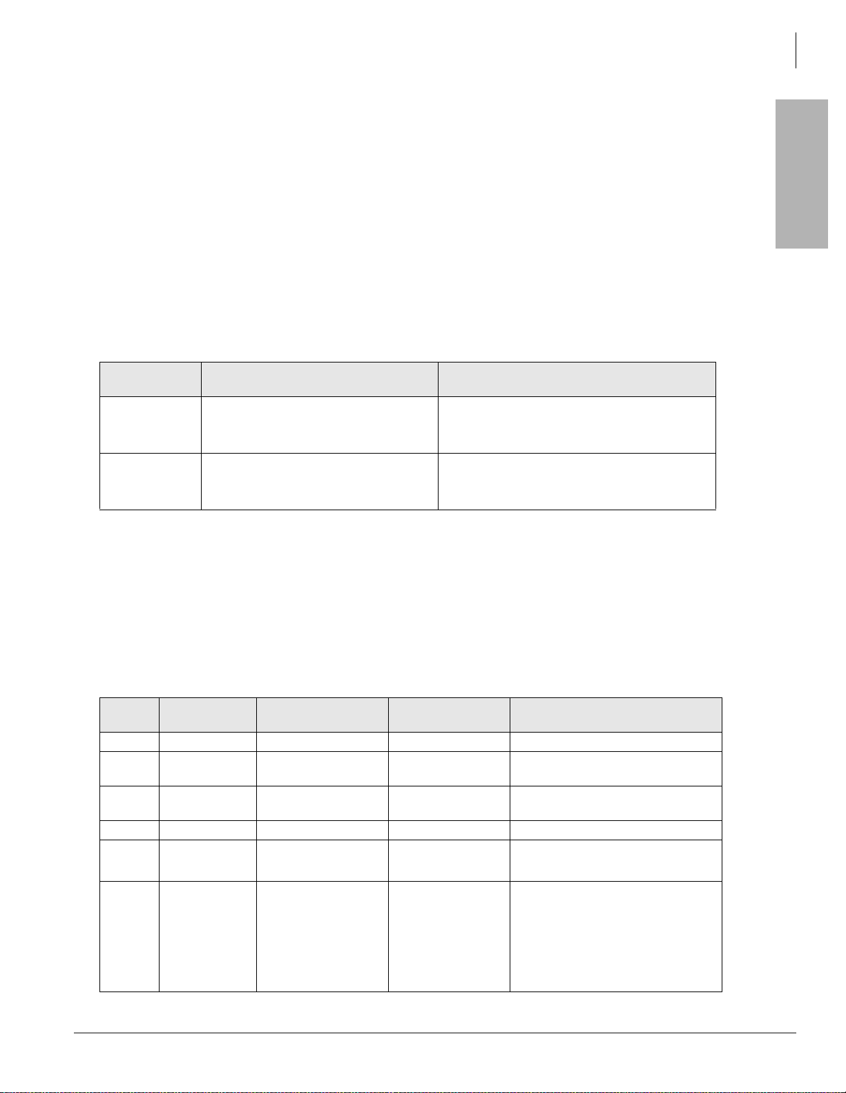
Strata CTX Programming Guidelines
Step 1: Use Default Auto-programming to Start Up
Station PDN Auto-programming
When auto programming recognizes installed stat ion PCBs, it assigns PDNs in numer ica l o rde r a s f oll ows:
• Auto programming assigns PDNs to station PCB equipment numbers (cabinet, slot, circuit) in
equipment number order. All installed station PCB circuits will be assigned a PDN regardless of the
circuit type, digital (BDKU/BDKS, PDKU) or analog (RSTU).
• PDN 200 or PDN 2000 (depending on the system size) is assigned to the station circuit having the
lowest equipment number in the system, then the PDN is incremented by one digit and assigned to the
next highest station equipment number and so on. See Table 1-2.
• Program 205 Feature Button Setting – A Primary DN (PDN) is assigned to
telephone according to its equipment number (cabinet, slot, circuit) position. DND is assigned to FB20
on 20-button telephones and is not assigned on 10- and 14-button telephones.
Table 1-2 Auto-Programming for Station Pri mary Directory Number
)% on each digital
Programming
Strata CTX
First dig it
2
3
CTX100 and CTX670 without BBMS
and BEXS Installed on Processor
Primary DNs (3-digits)
200~299 dependin g on quanti ty of stati on
PCBs installed
Primary DN (3-digits)
300~399 depending on qty. of station
PCBs installed
Primary DNs (4-digit)
2000~2571 depending on qty. of station PCBs
installed
CTX670 with BBMS and BEXS
Installed on Processor (First Digit is 2)
CO Line Auto-programming
Table 1-3 shows the CO line PCBs that will be recognized and set in Program 100 during auto-
programming. The default data for CO line Incoming Line Groups (ILG), Outgoing Line Groups (OLG),
and CO line service type is set as shown in Table 1-4.
Important! PCBs must be installed per the rules in the CTX I&M manual, Configuration Chapter,
Worksheet 6 and Worksheet 7.
Table 1-3 Auto-Programming for CO line PCB Recognition (Program 100)
PCB
Code
000 - No PCB or RRCU None or Remote cabinets
001 RCOU, RGLU
005 RCOU+RCOS
006 RDDU 4 analog DID lines Direct Inward Dial lines
007 RDTU2
008 RDSU
PCB Name PCB Circuit Type Parameter setting Comments
4 analog Loop or
ground start lines
8 analog loop start
lines
16 or 24 digital T1
lines
4 Standard telephone
and for digital
telephone
PCM Highway:
16 or 24
1
Direct Incoming Termination (DIT)
lines
Direct Incoming Termination (DIT)
lines
T1 Direct Incoming Termination (DIT)
lines
Standard telephone and DKT2000
and DKT3000 without S-OCA
(DKT3000 limitations: DKT2000, 16
character LCD display on DKT3000,
DKT3000 LCD Feature ke y do es no t
function, DKT3014 large scree n LCD
does not display).
Strata CTX Programming - Part 1: Getting Started 11/03 1-3
Page 24
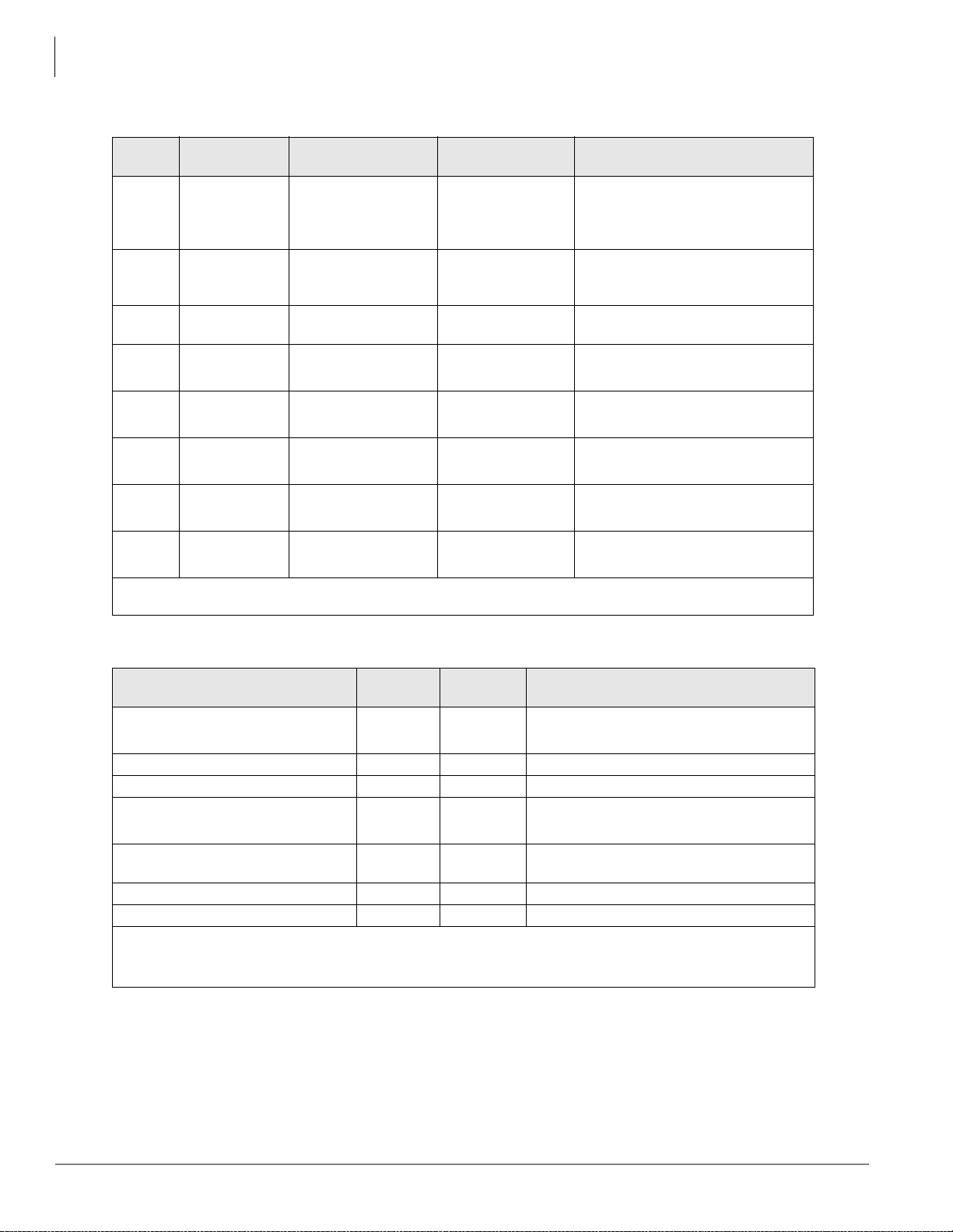
Strata CTX Programming Guidelines
Step 1: Use Default Auto-programming to Start Up
Table 1-3 Auto-Programming for CO line PCB Recognition (Program 100)
PCB
Code
009 RCIU2+RCIS
010 RMCU+RCMS
011 REMU, BVPU
012 RBSU
013 RBSU+RBSS
014 RPTU
015 RBUU
016 RBUU+RBUS
1. If the slot next to an in sta ll ed RDT U or RPTU is vacant, 24 line or channels wil l be in stalled; If the slot n ext to
an installed RDTU or RPTU is occupied by another PCB, 16 lines or channels will be installed.
PCB Name PCB Circuit Type Parameter setting Comments
4 or 8 Caller ID
interface
2 or 4 E911 analog
CAMA lines
4 analog Tie lines, 4
VoIP circuits
2 ISDN BRI (S/T)
circuits
4 ISDN BRI (S/T)
circuits
16 or 24 ISDN PRI
channels
2 ISDN BRI (U)
circuits
4 ISDN BRI (U)
circuits
TIE Type:
Two TIEs
TEI Type:
Two TIEs
PCM Highway:
16 or 24
TEI Type:
Two TIEs
TEI Type:
Two TIEs
1
(continued)
Caller ID interface for RCOU/RCOS
and RGLU analog CLID lines. Note:
The same Prg100 code (009) is used
for RCIU2 with or without RCIS.
CAMA lines Note: The same Prg100
code (009) used for RCIU2 with or
without RCIS.
Tie lines
ISDN BRI CO lines
ISDN BRI CO lines
ISDN BRI CO lines
ISDN BRI CO lines
ISDN BRI CO lines
Table 1-4 Auto-Programming of Line Groups and Service Types
CO line type
RCOU/RCOS and RGLU analog loop
and ground start
RDDU analog DID 1 2 DID, wink – no default DID numbers
RDTU (T1) 1 3 DID – no default DID numbers
RMCU/RMCS analog CAMA 1 RBUU/RBUS and RBSU ISDN BRI -
set as CO side
ISDN PRI 2 5 DID – no default DID numbers
REMU analog E&M 3 6 Non-QSIG
1. The line number is assigned to al l li ne s in the num eri ca l ord er ac co rdi ng to the line PCB cabinet plac em en ts.
Example: Line number 1 will be on the first circuit of the line PCB placed in the lowest cabinet/slot number.
2. OLG:1 is created even if there is are no analog line PCBs installed.
OLG
Prg 306
11
2 4 DID – no default DID numbers
ILG
Prg. 304
CO Service Type
Direct In Termination (DIT) to the first PDN.
(200 or 2000 – see Table 5)
Direct In Termination (DIT) to the first PDN.
(200 or 2000 – see next table)
1-4 Strata CTX Programming - Part 1: Getting Started 11/03
Page 25

Table 1-5 Auto-Programming of Miscellaneous Line Parameters
Strata CTX Programming Guidelines
Step 1: Use Default Auto-programming to Start Up
Item Settings
DIT line ringing assignment
Program 310
DID numbers - not assigned.
Program 309
Format Setting for DIT (T1) Zero Code Suppress = B8ZS, Frame Format = ESF.
Setting for CAMA
Setting for ISDN BRI CO
Setting for ISDN PRI CO
Setting for E&M Tie lines
All of the ringing destinations of DIT lines are the first PDN:
PDN 200 for CTX100 and 2-cabinet CTX670
PDN2000 for 2~7 cabinet CTX670.
The destination of DID is not assigned. DID numbers and ringing
destinations must be assigned manually from CTX WinAdmin or the
programming telephone.
The destination of internal notification is the first DN 200 or 2000 in the all
operation mode (DAY1, Day2, and Night).
Common D channel is not assigned. 1 channel group is assigned to each
BRI PCB installed. The c ha nne l group number is assig ned in ord er to ea ch
BRI interface in the order in which the BRI PCBs are installed. The
destination of DID is not assigned.
Common D channel is not assigned. 1 channel group is assigned to each
PRI PCB installed. The c ha nne l group number is assig ned in ord er to ea ch
PRI interface in the order in which the PRI PCBs are installed. The
destination of DID is not assigned.
The node number and the other setting for networking are not assigned
automatically
The destination of Progr am 3 18, No Calling Pa rty Numbe r and Out Of Search for DID number, is assigned
to the first Primary DN of the system (200 or 2000) in the all system operating modes (Day1,Day 2, and
Night).
Programming
Strata CTX
The DIT line (groun d and loop) destinations of all trunks which gene rated automatical ly ar e set as the first
PDN 200 or 2000 depending on the system size – see Table 1-4.
BIPU Settings
Table 1-6 BIPU-M Automatic Settings
Item Description Settings
Card Type Card Type BIPU
In the order of smallest number of the slot
where BIPU is inserted
IP Address (BIPU) IP address of BIPU
Subnet mask (BIPU)
Default gateway
Subnet mask of BIPU
substrate
Default gateway of BIPU
substrate
192.168.254.200
.201
.202/.......
Private address will be set.
255.255.255.0
0.0.0.0
Strata CTX Programming - Part 1: Getting Started 11/03 1-5
Page 26
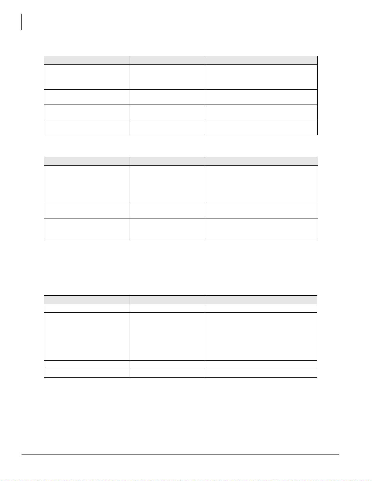
Strata CTX Programming Guidelines
Step 1: Use Default Auto-programming to Start Up
Table 1-7 IPT Automatic Settings
Item Description Settings
DN Setting
Accommodated terminal setting
(Station ID)
Accommodated terminal setting
(IP Address)
Accommodated terminal setting
(MAC addresses)
Table 1-8 System Related Basic Settings
Item Description Settings
QOS Control
Station ID
Terminal authentication setting
DN setting of the terminal
accommodated in BIPU
Parameter setting of Station
ID in BIPU
Parameter setting of IP
address in BIPU
Parameter setting of MAC
addresses in BIPU
Setting of priority control by
Diffserv/IEEE802.1p
Automatic setting of Station
ID
Application or no n applic ation
of connection restrictio n
function using MAC address
The number plan conforms to BDKU16.
Assigned in the order of the lowest slot
number.
Station ID = PDN
IP address = 0.0.0.0
MAC addresses = (no data)
Use of Diffserv: Not applicable
Set value of DSField = 0
Use of IEEE802.1p: Not applicable
Priority level: Voice
Not allowed
Not apply
BIPU-Q1A Initia l Programming
After initializing the CTX System with BIPU for Strata Net over IP, Strata CTX detects the BIPU card for
Strata Net over IP and basic programming is set automatically.
T ab le 1-9 BIPU-Q1A Automa tic Setting s
Item Description Settings
Card Type Card Type BIPU-Q1A
In the order of smallest number of the slot
where BIPU is inserted
IP Address (BIPU) IP address of BIPU-Q1A
Subnet mask (BIPU) Subnet mask of BIPU-Q1A 255.255.255.0
Default gateway Default gateway of BIPU-Q1A 0.0.0.0
192.168.254.800 for 1st BIPU
.801 for 2nd BIPU
.802 for 3rd BIPU
Private address will be set.
1-6 Strata CTX Programming - Part 1: Getting Started 11/03
Page 27
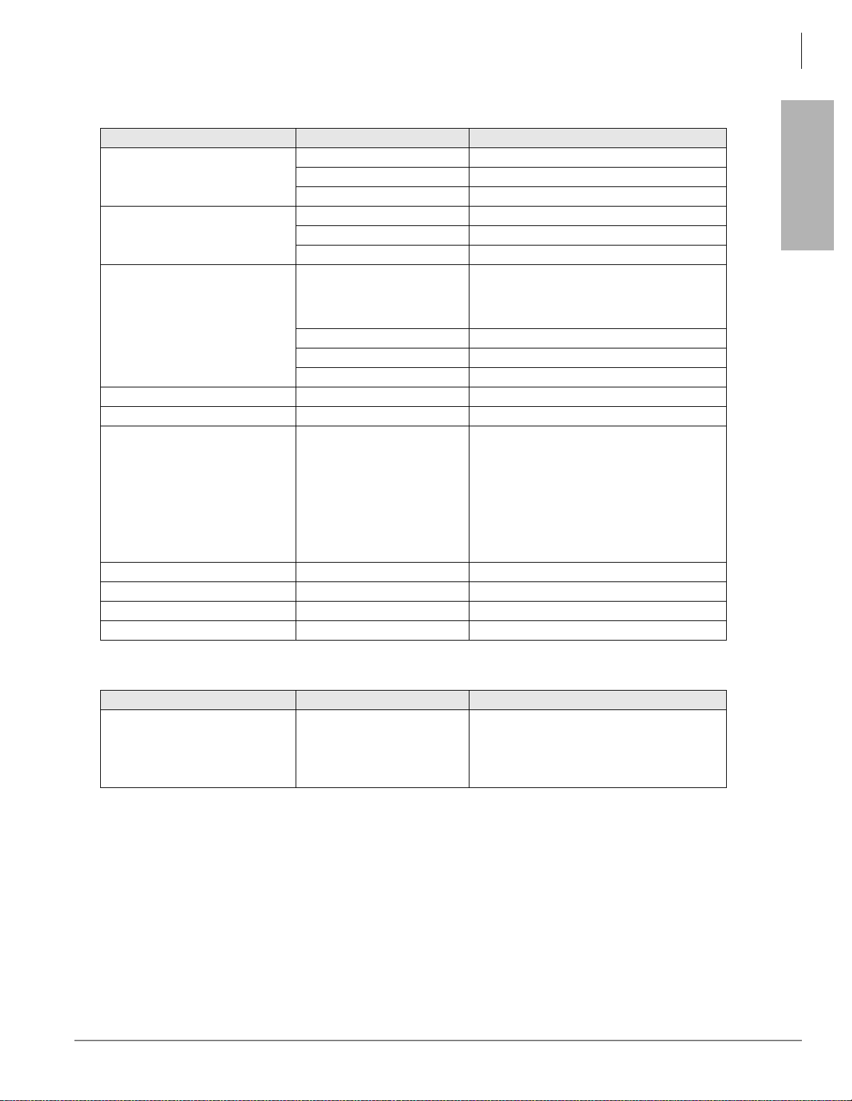
Table 1-10 IP-Trunk Information
Strata CTX Programming Guidelines
Step 1: Use Default Auto-programming to Start Up
Program Description Settings
ILG Number 7
ILG
Kind of Trunk (Analog/ISDN) ISDN
Type of Trunk TIE
OLG Number 4
OLG
Kind of Trunk (Analog/ISDN) ISDN
Type of Trunk TIE
1: 1st BIPU
CG Number
ISDN Trunk
2: 2nd BIPU
3: 3rd BIPU
Type of Protocol IP
ILG 7
OLG 4
Voice Coding Procedure CODEC (G.711, G.729A) G.711
Index of Voice attribute table (1~256) 1
Packet Interval: 20ms
Type of Jitter buffer: Fixed
Size of Jitter buffer: 1
Parameter of voice attribute table -
Max Acceptable Delay: 1
Measure Time: 1000ms
Packet Loss Ratio: 5
Packet discard ratio: 5
D-ch Establish/Release D-ch Establish/Release D-ch Release by Call Released
Fast Connect Procedure - Apply
Negotiation Negotiation of H.245 Un-Apply
IP address for Node ID IP Address IP address
Programming
Strata CTX
Table 1-11 System Information
Item Description Settings
Diffserv: Disable
QoS Control
Priority Control by Diffserv .
IEEE802.1p
DS Field: 0
IEEE802.1p Disable
Priority: Voice (6)
Strata CTX Programming - Part 1: Getting Started 11/03 1-7
Page 28
Strata CTX Programming Guidelines
Step 1: Use Default Auto-programming to Start Up
CTX Processor NIC Interface TCP/IP Auto-programming
The following are the initial values of the LAN data that is automatically created for the system.
• Network TCP/IP. See “916 IP Configuration” on page 10-14.
• IP address – 192.168.254.253
• Sub network master – 255.255.255.0
• Default gateway – 0.0.0.0
• IP routing table – Not used.
• SNMP Agent settings
• Community name – communityName
• IP address – 0.0.0.0 (not restricted by the IP address of the access source)
• Privileg es –
• community-id – 1
• User level – Super user
• Trap destination
• Community name – Nothing
• IP address – Nothing
• Modem PPP Server settings
WRITE
• IP Address – 192.168.255.254 (Strata CTX modem fixed IP address for Dial-up connecti ons).
Public Numbering Plan Analyzed Digit Numbers (Program 117)
Public Numbering Plan
Analyzed Number
1NXX 11
N11 3
NXX 7
N = 2~9 and X = 0~9
Public Numbering Plan
Analyzed Digit Number
E911 Emergency Cal l to Outgoi ng Line Group (Program 550)
Emergency Call Group
Number
11
OLG1
E911 Emergency Call Destination (Program 400)
System Mode
DAY1 1 200 or 2000 (the first PDN)
DAY2 1 200 or 2000 (the first PDN)
NIGHT 1 200 or 2000 (the first PDN)
The emergency call destination is set for the first PDN as 200 or 2000 in the all operation mode (DAY1,
Day2, NIGHT).
Emergency Call Called Number
Index
Emergency Call Called Number
1-8 Strata CTX Programming - Part 1: Getting Started 11/03
Page 29

Strata CTX Programming Guidelines
Step 2: Plan Your System Requirements
Default Feature Access Codes
Refer to “102 Flexible Access Codes” on page 4-3.
Note For DKTs, assign only the PDN numbers. Do not program any other Flexible Buttons or features in
to the phones. Strata CTX automatically recognizes and sets up digital telephone stations.
Step 2: Plan Your System Requirements
Plan for your Strata CTX system requirements in detail before beginning your installation. Use record
sheets wherever they are provided to document your installation requirements. The following are some
areas to consider:
• Flexible Numbering Plan (102) – Planning your Flexible Numbering requirements is essential to a
smooth installation. Trunk group access and station range requirements are especially important areas
of consideration.
• COS (103) – Determine the Class of Service (COS) requirements for your station and trunk groups.
There are up to 32 possible COS plans.
• DRL (111) – Define up to 16 Destination Restriction Level (DRL) assignments.
Important! Destination Restriction is an expanded feature of what has traditionally been known as Toll
Restriction. Toll Restriction is only one f acet o f S trata CTX’s Destinati on Restri ction fe atur e.
Refer to Destination Restriction in this manual when programming Toll Restriction
requirements.
Programming
Strata CTX
• FRL and QPL (506) – Define up to 16 Facilities Restriction Level (FRL) and Queuing Priority Level
(QPL) assignments.
Step 3: Program CTX for First Time
Follow the steps below to pro gra m t he Strata CTX for the firs t ti me. Following this initial setup procedure
enables you to pe rform a stan dard S trata CTX setup wit h common Syste m and S tatio n default assignme nts.
Toshiba recommends adherence to these procedures for initial setup.
1. Card Assignments (100) – Choose Sy stem > Card Assignment. It i s not necessary to physically install
PCBs prior to programming Strata CTX.
If you physically install your PCBs prior to initial setup, CTX WinAdmin automatically recognizes
PDKU, BDKU/BDKS, RSTU, RCOU/RCOS and RGLU PCBs and assigns default stations and trunks
automatically. All other PCBs are assigned manually. See “100 Cabinet Slot PCB Assignments” on
page 4-1 for mor e details.
2. ILG Assignment (304) – Choose Trunk > ILG to assign Incoming Line Groups (ILG). See “304
Incoming Line Group Assignment” on page 6-2 for more details. ILGs enable line groupings of shar ed
Class of Service features for incoming call handling.
3. OLG Assignment (306) – Choose Trunk > OLG to assign Outgoing Line Groups (OLG). See “306
Outgoing Line Groups” on page 6-4 for more details.
Strata CTX Programming - Part 1: Getting Started 11/03 1-9
Page 30

Strata CTX Programming Guidelines
Step 3: Program CTX for First Time
4. Trunk Assign ment (3 00) – Choose T r unk > Basic. Set up you r T runks in the following or der (see “300
Trunk Assignment” on page 6-6 for more details):
• Loop Start Trunks
• Ground Start Trunks
• T1 Trunks
• Tie lines
•FX lines
•PRI lines
• BRI lines
5. Station Assignment (200) – Choose Station > Basic. Set up your stations in the following order (see
“Assignment” on page 5-1 for more details):
• DKT Stations
• Standard Stations
• Voice Mail (VM) Ports
• Attendant Positions
• Automatic Call Distribution (ACD) Pilot DNs
•Door Phones
6. Create Station Links – Create the fo llowing groups wherever applicable and set stations to link as
necessary.
• Hunt Groups using Programs 209 and 218
• Paging Groups using Program 502
• Call Pickup Groups using Program 210
• Park Orbits using Program 102
• Paging Devices using Program 503
7. Backup Data – Choose Operation\Data Backup. Mak e sure t he Smart Media ca rd is pr operl y format ted
(see “908 SmartMedia” on page 10-4) prior to running backup. See “910 Data Backup” on page 10-13
for details.
8. Continue programming Strata CTX details.
1-10 Strata CTX Programming - Part 1: Getting Started 11/03
Page 31

Strata CTX Programming Guidelines
Step 3: Program CTX for First Time
Review Program Flow
The basic program flow needed to set up Strata CTX is shown below. The figure displays the most critical
programs in the left column and migrates right to optional programs. Also, programming flows from
specific (left) to genera l (ri ght ).
Card Assignment
(Program 100)
Programming
Strata CTX
Create ILGs
(Program 304)
Create OLGs
(Program 306)
Recommended*
Planning the following before
proceeding.
Flexible Numbering Plan
(Program 102):
Trunk Group Access Plan
Station Range Plan
Create COS Plan (up to 32)
(Program 103)
Create DRL (up to 16)
(Program 111, 532~533)
Define FRL and QPL
meanings (up to 16)
LS Trunks
GS Trunks
TI Trunks
Tie Lines
FX Lines
PRI Lines
BRI Lines
DKT Stations
STD Stations
VM Ports
Attd Positions
Pilot DN's (ACD)
Door Phones
BRI Lines
Create Station Links
Hunt Group
Paging Group
Call P.U. Group
Park Orbits
Paging Devices
Admin
Services
LCR/TR
System Program
5862
*Planning out these details
in advance enables Strata CTX
setup to proceed smoothly.
Strata CTX Programming - Part 1: Getting Started 11/03 1-11
Page 32

Strata CTX Programming Guidelines
Step 4: Identify Program Sequences
Step 4: Identify Program Sequences
Use the following tab les to quic kly ide ntify the programs needed to ful fill you r setup req uiremen ts. See th e
Index to correlate program numbers and their functions.
Station Setup
Use the following table to quickly access the programs needed to set up Station requirements.
Station
Type
DKT PDN 100 200 204 208 205
ISDN Ext 100 202 217
Pilot DN 540
Station Hunting 209 218
Call Pickup Groups 210
Emergency Ringdown 216
Paging Groups 502
Station Speed Dial 516
Assignment Run Programs in Sequence from left to right.
PhDN 205 206
DADM 204 213
DDSS 214 215
Attd 100 200 204 208
Ext 100 200 208
VM 100 200 204 206 209 218 579 580
Trunk Setup – Analog
Use the following table to quickly access the programs needed to set up analog Trunk requirements.
Trunk
Type
LS/GS
Tie line
DID
Assignment Run Programs in Sequence from left to right.
Basic 100 304 306 300
Ring 310
Timer 308
DISA 311
Basic 100 304 306 300
Timer 308
DISA 311
Basic 100 304 306 300
Ring 309
Timer 308
DISA 311
DNIS/ANI 313
Intercept 318 319
1-12 Strata CTX Programming - Part 1: Getting Started 11/03
Page 33

Strata CTX Programming Guidelines
Step 4: Identify Program Sequences
Trunk Setup – T1
Use the following table to quickly access the programs needed to set up T1 Trunk requirements.
Programming
Strata CTX
Trunk
Type
LS/GS
Tie line
DID
Assignment Run Programs in Sequence from left to right.
Basic 100 304 306 300
Data 315
Ring 310
Timer 308
DISA 311
Basic 100 304 306 300
Data 315
Timer 308
DISA 311
Basic 100 304 306 300
Data 315
Ring 309
Timer 308
DISA 311
DNIS/ANI 313
Intercept 318 319
Trunk Setup – ISDN PRI
Use the following table to quickly access the programs needed to set up ISDN PRI Trunk requirements.
Trunk
Type
DID
Tie line
Notes
1. Each CBC Group may require one ILG and one OLG.
2. Do not assign ILG/OLG using this program.
3. Assign ILG and OLG using Program 323.
Assignment Run Programs in Sequence from left to right.
Basic 100 304 306 302 320
Ring 309
Timer 308
DISA 311
DNIS/ANI 313
Intercept 318 319
CNIS 321 322
Basic 100 304 306 302 320
Ring 309
Timer 308
D-share 100 304 306 302 320 316
CBC 100 304
1
306
1
302
2
320 323
3
Strata CTX Programming - Part 1: Getting Started 11/03 1-13
Page 34

Strata CTX Programming Guidelines
Step 4: Identify Program Sequences
Miscellaneous
Use the following table to quickly access the programs needed to set up other Strata CTX features.
Feature Run Programs in Sequence from left to right.
Account-Codes 570 571 103 506 306
Automatic Busy Redial (ABR) 103 208 104
Automatic Call Back (ACB) 104
Automatic Camp-On 304
Auto-Release of CO 308
Background-Music (BGM) 102 103 109
Call Forwarding 103 200 217
Call History 204 205
Call Park Orbit 104 102
Call Xfer W/ Camp-On 103
COS-Station 200 202
COS-CO 304 306
Credit-Card Calling 105 111 306
Day/Night service 500 106 112 1 1 3 103 105
Identification Services 309 318 579
Digital PAD 107 114
Direct Inward Dialing 309 318 304
DISA 311
Direct Inward Termination 304 310
Do not Disturb (DND) 103 204 205 102
Door Lock Control 104 204 508 205
Door Phones 102 507 573
DTMF DP Compatible 104
DTMF BackTone 204
DTMF Signal Time 579 104
E911 105
Executive Override 103 105
External Ringing Repeat 300 204
Flash 308 205 102 103
Flexible Numbering 102
Group Paging 502 503 102
Least-Cost-Routing (LCR) 520 521 522 523 524 525 526 528 529 103
Line Group 304 305 306 307 317 302 323 300
Message-Wa iti ng Light 204 102 579
Music-on-Hold 102 105 109 309 310
Off-Hook Camp-on 104 200 217
Network Call – Incoming 102 656
Network Call – Outgoing 102 651 653 654 655
Out-Going calls 200 217 104
Ringing-Transfer 105
SMDI 200 202 579 580
200
202
217 550 104 306
1-14 Strata CTX Programming - Part 1: Getting Started 11/03
Page 35

Strata CTX Programming Guidelines
Step 4: Identify Program Sequences
Feature Run Programs in Sequence from left to right.
Station CO L ine Access 204
SMDR 512 513 514
Tandem Connection 103 104 300
DR Override by System’s
Speed Dial
Destination Restriction 200 202 306 650 530 531 532 533 534
Tone-First/Voice-First 204 206
Travelling COS 105 200 510
Voice -Ma il Interface
See “Voice Mail Set Up” on
page A-1
Emergency Ring-Down 216
Relay Services 515
System Call-Forward 200 217 104 500 504
Call Pick Up 210 103 200 205 102
105
100 200 209 218 579 580 803 804 309 318
Programming
Strata CTX
Strata CTX Programming - Part 1: Getting Started 11/03 1-15
Page 36

Strata CTX Programming Guidelines
Step 4: Identify Program Sequences
1-16 Strata CTX Programming - Part 1: Getting Started 11/03
Page 37

726+,%$ Telecommunication Systems Division
Digital Business Telephone Systems
Part 2: CTX WinAdmin Programming
November 2003
Page 38

Page 39

CTX WinAdmin Overview 2
CTX WinAdmin is a powerful Microsoft® Wi ndows® based telephone system management tool used to
program, maintain and upgrad e th e Strata CTX Digital Busines s Telephone System. CTX WinAd min us es
a variety of networking and software technologies as follows:
• Virtual Local Area Network (LAN) – System Administrators can connect their PC to
Strata CTX via a network interface jack or modem. CTX WinAdmin views the Strata CTX system as a
LAN providing a stable environment in which to program and access data.
• Windows Management Instrumentation (WMI) – enables query-based info rmation retrieval and
event notification. WMI is an access mec hanism which enables CTX WinAdmi n to access, monitor,
command and control Strata CTX.
• Virtual Web Server and Manager – creates a virtual World Wide Web environment in Strata CTX.
This technology enables CTX WinAdmin to view Strata CTX as if it were an Internet Serv ice Provider
(ISP), providing secure passage for System Administrators.
• Microsoft Internet Explorer® browser access – Virtual Web Service enables System Administrators
to access Strata CTX using the Internet Explorer browser.
• CTX WinAdmin Graphical User Interface (GUI) – Sophisticated programming tasks are just a
click-of-the-mouse away with CTX WinAdmin’s GUI.
• Mobile Access – enables System Administrators to program, maintain, and/or upgrade a
Strata CTX from any mobile location with an Internet connection—without ever leaving the office.
• Internet Access – CTX WinAdmin uses Microsoft IP technology to enable access to your Strata CTX
as easy as browsing the World Wide Web.
• Personal Web Server and Manager – Microsoft ’s Personal Web Server and Manager option package
enables you to build a web environment between your Strata CTX and your PC.
CTX WinAdmin
Overview
• Internet Explorer – provides a stable environment in which to program, maintain and upgrade your
Strata CTX.
CTX WinAdmin’s tight integration of the above technologies provide System Administrators with
convenient, stable, user friendly and comprehensive access to Strata CTX system information.
CTX WinAdmin can connect direct ly to your Strat a CTX Digital Business Telephone System via Net work
Interface (included with Strata CTX’s BECU board and required on your PC) and Modem Interface.
Mobile System Administrators can access a Strata CTX system from any location that provides Internet
access.
Strata CTX Programming - Part 2: CTX WinAdmin Programming 11/03 2-1
Page 40

CTX WinAdmin Overview
CTX WinAdmin Main Screen
CTX WinAdmin Main Screen
After you start CTX WinAdmin, log in and connect to the CTX, the main screen (shown below) displays.
Verify the information on this screen. It contains the System type and Software version.
Auto Flyover On/Off Button
Program Viewer
Program Menu
• Auto Flyover On/Off Button – You can click this toggle button to turn on or turn off flyovers.
• Program Menu – The primary tool used to navigate through CTX WinAdmin. Click the Expand or
Collapse buttons at the upper left corner to expand or collapse the Program menu.
• Program Viewer – This area is where the various programs and parameters are displayed as you
navigate through CTX WinAdmin.
Notes
• Y ou can ve rify the S trata CTX syst em type (C TX100 or CTX670) and the s oftware ve rsion on t he T itl e
screen shown above.
• The software version is organized as follows:
● Example: AR1.01 M0010.00
● A = Country code (USA, Canada, Mexico).
● R1.01 = CTX Release 1.01
● M000xx.00 = Strata CTX software version.
2-2 Strata CTX Programming - Part 2: CTX WinAdmin Programming 11/03
Page 41

CTX WinAdmin Sub-screens
The CTX WinAdmin operates in a user friendly Windows environment featuring interactive Graphical
User Interface (GUI) screens.The Prog ram Viewer’s GUI is arranged to streamline the Strata CTX
programming process (see sample screen below).
CTX WinAdmin Overview
CTX WinAdmin Sub-screens
Toolbar
Program Details
CTX WinAdmin
Overview
Program Name
Program Menu
Tabs
Programming functions can b e accessed b y clicking on the appropr iate li nk in the Progr am Menu. The Day
Night Service (Programs 112, 106 and 113) screen is shown in the sample below.
Command Table Button
Toolbar
Special Buttons
Command Group Name
Programming
Parameters
Field Name
5698
Strata CTX Programming - Part 2: CTX WinAdmin Programming 11/03 2-3
Program Blocks
Program and Parameter Descriptions
Page 42

CTX WinAdmin Overview
CTX WinAdmin Sub-screens
The following features enable you to browse and program CTX WinAdmin efficiently.
• Program Blocks – CTX WinAdmin arranges many related programs in blocks to enable the
programmer to view essential and related programs on one screen.
• Program Tabs – You can access a variety of progr ams and f eatures by clicki ng the Pr ogram Tabs found
on some of the CTX WinAdmin screens.
• Programming Parameters – Choose values from scroll down menus.
• Command Group Name – Each program number and ti tle i s promine ntly di splay ed for e asy ref erenc e.
• Field Name – Each Field Name or parameter di splays and is coded with a prefix (
)%) number for easy
referencing.
• Program and Parameter Descriptions – Every program and parameter description displays in a
pop-up window by placing the mouse cursor over the program or parameter information.
• CTX WinAdmin Toolbar – The CTX WinAdmin Toolbar enables Strata CTX updates with a click of
your mouse button. The following option s are prov ided.
• Edit – CTX WinAdmin def aults to the Edit mode used to p rogram, mai ntain , or upgra de your Strata
CTX System.
• Cancel – Cancels the previous entry.
• Refresh – Displays the latest updates.
• Reset – Resets to set your Strata CTX to manufacturer’s default.
CAUTION! By pressing the Reset button, you ar e authorizing all data to be res et t o manufac tur ing
defaults. Any custom data entered will be lost.
• Submit – New data is held in CTX WinAdmin’s memory. Your Strata CTX is not updated with the
new settings until the Submit button is clicked.
• Close – Exits CTX WinAdmin and return to CTX Management Console Menu.
• Disconnect – Disconnects CTX WinAdmin from Strata CTX and terminates TCP/IP
Communications.
• Help – Enables the CTX WinAdmin Help files.
2-4 Strata CTX Programming - Part 2: CTX WinAdmin Programming 11/03
Page 43

• Command Table Button – This button
enables you to locate programs by
number or category (shown right).
From this table, you can click on a
program to open it.
Special Buttons
These buttons appear on some of the CTX WinAdmin screens.
CTX WinAdmin Overview
CTX WinAdmin Sub-screens
CTX WinAdmin
Overview
These buttons enable you to access the
most common programming tasks
quickly. For example, click on the List
button to view the Current Index Web
Page dialog box (shown right).
Clicking on any button lets you do the
following:
• Create – Create a new record using
system default values.
• Start – Starts a wizard.
• Add/Delete/Modify – Enables you to add/delete/modify entry(s). In some programs, click the Add or
Delete button for a dialog box to display. Enter the required data, then click Add or Delete.
• List – Lists all data.
• Copy – Enables you to copy all the information from one screen to another.
• Back/Next – Enables you to navigate forward and backward through the screens.
• Table View – Displays the appropriate table view. For example, clicking the DR Table View button
displays all the configured DRLs within the system.
• Print – Enables you to print to a local printer.
• Refresh – Enables you to get the most updated information.
Strata CTX Programming - Part 2: CTX WinAdmin Programming 11/03 2-5
Page 44

CTX WinAdmin Overview
CTX WinAdmin Sub-screens
Tabl e Views
Some programs contain supporting tables views. These tables can be accessed from the Program Menu or
from the program itself, by clicking the Table view button. For example, the System Speed Dial Table
View can be accessed by clicking System > System Speed Dial Table View or by clicking the System
Speed Dial Table View button under Program 501 System > System Speed Dial.
Notes
• Depending on the speed of your PC and the size of your database, the table may take several minutes
to download.
• Once table view displays, you can minimize the screen or send it to the background. It is an
independent window that can always be brought back to the front of the screen for reference.
The tables have the following functionality (See table view example below):
Previous Next
First 25 Entries Last 25 Entries
Navigation
Control Bar
Column Headers
Sort Indicator
Book Mark
6869
• Navigational controls – enable viewing or moving on a table by 25-entry screens. These controls help
sort information found in the table or view the table in full. These controls are found as Previous and
Next buttons above the header.
If you want to print or analyze the table, you can also select All from the Drop down between the
Previous and Next buttons to view the entire table in blocks of 25 entries.
In the Navigation Control bar, every button is dynamically activated or deact ivated. For exa mple, in the
figure above the Previous button is not active because the view starts with the first record. The Submit
is also not available because nothing has been changed.
• Sort – You can sort tables by clicking on the column header. The direction of the up/down toggles in an
Ascending or Descending sort. The color indicator pointing Up or Down in the Header row indicates
the column by which the sort is performed.
2-6 Strata CTX Programming - Part 2: CTX WinAdmin Programming 11/03
Page 45

CTX WinAdmin Overview
CTX WinAdmin Sub-screens
• Bookmark – You can bookmark a row on some tables by click ing on th e r ow. This enables you to move
forward and backward and come back to the original position with no problem.
Note The bookmark function is not provided in tables that have a Delete button, example “Hunt Group
Table View” on page 5-27. Tables that have a Delete button also have Select All and Unselect All
buttons.
• Edit/Refresh/Print bu ttons – You
can edit, refresh or print the table
by clicking the appropriate
buttons at the top of the screen.
In some tables the Edit button
toggles between View Collected
Data and Edit. Clicking t he Edit
button displays the following
screen.
The Edit function works for the
Name, Number and Destination
columns.
Use the Refresh button if you
add, delete or make changes to
table entries, in Programs that
feed tables or in Guide pages.
CTX WinAdmin
Overview
The Print button enables you to
print tables. However, when you click the Print button, onl y the pa rt of the table that i s dis played o n the
screen prints. Use the sc ro ll bar t o Print beyond what is displayed. It wi l l the n aut omat ic all y print from
where the last screen ended.
Strata CTX Programming - Part 2: CTX WinAdmin Programming 11/03 2-7
Page 46

CTX WinAdmin Overview
CTX WinAdmin Sub-screens
2-8 Strata CTX Programming - Part 2: CTX WinAdmin Programming 11/03
Page 47

Installation 3
This chapter shows you how to insta ll CT X W inAdmi n softwar e on your PC and di scusse s how to conne ct
that PC to the Strata CTX system .
PC Hardware Requirements
The following table shows the minimum PC requirements for CTX WinAdmin and WinCTX to operate
properly:
Hardware Windows XP Professional Windows 2000
300 MHz or higher processor clock
Computer/Processor
Memory 128MB RAM 128MB RAM
Hard Disk 1.5GB of available space
SVGA Card and Monitor Yes Yes
CD-ROM Drive Yes Yes
Network Interface Card
(NIC) and/or PC Modem
speed. Intel Pentium or Celeron
processors; or AMD K6, Athlon or
Duron processors are recomm en ded.
Yes Yes
300 MHz or higher Pentium
2GB hard drive with a minimum of
650MB of free space
Installation
PC Software Requirements
The “Install CTX WinAdmin...” selection on t he CTX WinAdmin CD-ROM runs a Pre-installation Check
to determine if your PC meets the minimum software requirements for CTX WinAdmin to operate
properly. The Pre-installation Check tests for the following:
• Windows Operating System – CTX WinAdmin requires a Microsoft Windows XP Professional or
Windows 2000 Operating System (OS).
• Windows Option Components – The Pre-installation Check tests to see if Windows Option
Components, such as Internet Information Services and Management and Monitoring Tools are
installed on your PC. If they are not installed, your Windows OS CD-ROM will be required; or if your
PC has an Original Equipme nt Man ufa cturer (OEM) version of Windows, you may need the CD-ROM
that came with your PC.
Disclaimer: CTX WinAdmin has not been tested with Windows NT 4.0. This OS is not recommended. We
recommend that you upgrade your OS to Windows XP Pro or Windows 2000 Pro.
Note CTX WinAdmin does not work on these operating systems: Windows XP Home, Windows ME,
Windows 98, Windows 95, and MS-DOS.
Strata CTX Programming - Part 2: CTX WinAdmin Programming 11/03 3-1
Page 48

Installation
Step 1: Install CTX WinAdmin Software
• Windows 2000 Service Pack 2 (SP2) – If not found, follow the steps given on the CTX WinAdmin
CD-ROM to install SP2.
• Internet Explorer (IE) – If IE 5.5 or greater is not found, follow the steps given on the CTX
WinAdmin CD-ROM and install it from there.
Note Windows XP Professional automatically installs IE 6.0 so installing IE 5.5 is not needed.
CAUTION! Toshiba recommends not to install MS Network Monitor on WinAdmin PCs because
MS Network Monitor software which is provided on the Microsoft System
Management Server (SMS) production CD-ROM causes problems with the Windows
WMI SNMP component needed to run WinAdmin.
Step 1: Install CTX WinAdmin Software
1. Insert the CTX WinAdmin CD-ROM into your CD-ROM drive. Clic k “Install CTX WinAdmin...”. The
CD-ROM runs a Pre-inst al lat i on c heck, determines the OS y ou h ave, then checks for a ll ot her software
requirements.
If the correct OS and all requirements were found on your PC, the “Pre-installation Check Complete!”
screen displays. This enables you to perform any of the following:
• First-time installation: click “Install Now”. Follow the prompts. Choose “Custom” to browse to
the drive on which you wa nt to install th e software or “Complete” to install imm ediately on the C:
drive.
• If upgrading from a previ ous version: click “Upgr ade Now”. Select “Complete” to inst all the new
version on the C drive, select Custom to select another drive. The CTX WinAdmin Custom Profile
folders will remain on the C drive or copied to the selected drive.
• If installing over the same version: click Install Now. You will be prompted to “Repair” or
“Remove.” Repair fixes corrupted files and registry entries. Remove removes the existing version to
enable you to reinstall the same version as a new clean install.
• If your PC did not pass the Pre-installation check and a requirement was not found: see the
details in “Requirements Not Found” on page 3-3.
CAUTION! Do not open and/or run other applications during installation as this may corrupt the
installation and/or other software on your PC. Installation takes several minutes.
2. Once installation is complete, if the Windows Internet Wizard displays when you click on the CTX
WinAdmin icon, enter the settings below if using a NIC or modem connection. This establishes a
preliminary path to bring up the CTX WinAdmin log-in screen.
• Windows XP Pro: If the Windows “Welcome to the New Connection Wizard” comes up, you have
not yet configured your Internet connection. Follow the prompts and select: Next > Connect to
Internet > Next > Set up my co nnec tion manuall y > Next > Conn ect u sin g broa dband co nnect th at is
always on > Finish. Exit the wizard screen.
• Windows 2000: If t he Windows “W elcome to the Inter net Con nec ti on Wizard” comes up, you have
not yet configured your Internet connection. Follow the prompts and select: I want to set up my
Internet connection manually > Next > I want to connect through a local area network > Next >
Automatic discovery o f Prox y serv er > Next and No to Set up Your Interne t Email Account > Next >
Finish.
3. Go on to “Step 1: Install CTX WinAdmin Software” on page 3-5.
3-2 Strata CTX Programming - Part 2: CTX WinAdmin Programming 11/03
Page 49

Step 1: Install CTX WinAdmin Software
Requirements Not Foun d
Service Pack 2 Not Found - Windows 2000
If Service Pack 2 was not found on your Windows 2000 OS, follow these steps.
1. Click the “Windows 2000 Service Pack 2 Not Found” line . A help screen appears. Locat e a nd cl ick the
“Install SP2 Now” link. SP2 installation will begin.
2. Follow the prompts to install SP2.
3. At the end of installation you wi ll be pr ompt ed t o restart your PC. Do so, log bac k in to Windows 2000,
then reinsert the CTX WinAdmin CD-ROM and select “Install CTX WinAdmin. ..” from the Mai n
Menu.
Internet Explorer (IE) 5.5 or Greater Not Found - Windows 2000
1. Click the “Internet Expl orer 5.5 or Grea ter Not Fo und” lin e. A h elp s creen will appe ar. Locate and click
the “Upgrade to IE 5.5 Now”. The upgrade will begin. Follow the prompts to upgrade to IE 5.5.
2. At the end of installation you will be prompted to restart your PC. Do so, log back into Windows 2000.
3. Reinsert the CTX WinAdmin CD-ROM and select “Install CTX WinAdmin...” from the Main Menu.
Installation
Note We suggest using IE 6.0 or higher with CTX WinAdmin to enable lists to be displayed in numeric
order.
Internet Information Services (II S) Not Found - Windows XP Pro/Windows 2000
If IIS was not found, follow the steps below.
CAUTION! Installing Internet Information Services (IIS) on PCs connected to a LAN and/or the
Internet may cause security issues - such as making your PC more susceptible to
intrusion and/or computer viruses. A direct connection between your PC and Strata
CTX reduces, but does not eliminate security issues.
• In all cases, always have a virus program with the latest virus tables running real-time on your PC.
• An NTFS file system is recommended if you are connected to a LAN and/or Internet. See your
Windows Help files f or more details .
• Consult the Microsoft Knowledge Base on the Internet for updates on Windows security issues.
• Check if you have the I386 folder loca ted on you PC, if not have your Windows OS CD-ROM ready as
you will be asked to insert it.
➤ Installing IIS using Windows XP Pro or Windows 2000 CD-ROM
1. Windows XP Pro and Windows 2000: Click Start > Settings (2000 only)> Control Panel > Add/
Remove Programs > Add/Remove Windows Components. Checkmark Internet Information Services
(IIS). Under IIS option, check mark FTP and do not uncheck any items that are already checked. If
Management and Monitoring Tools were also Not Found you may checkmark this too. Click “Next”.
Installation
2. Follow the prompts and have your Wi ndows OS CD-ROM ready as you wil l be asked to insert it. If the
Windows autoplay menu runs after inserting the CD-ROM, close this screen.
3. Once installation is complete, reinsert the CTX WinAdmin CD-ROM and select “Install WinAdmin...”
from the Main Menu.
Strata CTX Programming - Part 2: CTX WinAdmin Programming 11/03 3-3
Page 50

Installation
Step 1: Install CTX WinAdmin Software
Note If your PC displays this error message
(shown right), insert the Windows OS
CD-ROM that came with your co mpute r
(Recovery or Companion type) and not
the Service Pack2 CD-ROM. Fo llow the
prompts to browse, open and install files.
Management and Monitoring Tools Not Found - Windows XP Pro/Windows 2000
If Management and Monitoring Tools were not found, follow the steps below.
1. Windows XP Pro and Windows 2000: Click Start > Settings (2000 only)> Control Panel > Add/
Remove Programs > Add/Remove Windows Components. Checkmark Management and Monitoring
Tools. If Internet Information Services (IIS) were also Not Found you may checkmark this too. Click
“Next”.
2. Follow the prompts and have your Wi ndows OS CD-ROM ready as you wil l be asked to insert it. If the
Windows autoplay menu runs after inserting the CD-ROM, close this screen.
3. Once installation is complete, reinsert the CTX WinAdmin CD-ROM and select “Install CTX
WinAdmin...” from the Main Menu.
WMI SNMP Provider Not Found - Windows 2000
If the WMI SNMP Provider was not found on your Windows 2000 PC, follow the steps below. Have your
Windows 2000 CD-ROM ready, you’ll be asked to insert it.
1. Click the “WMI SNMP Provider Not Found” line. A help screen appears.
2. Locate and click the “Instal l WMI SNMP Provider”. Follow the prompts to instal l WMI SNMP
Provider. Once complete, reinsert the CTX WinAdmin CD-ROM and select “Install CTX
WinAdmin...” from the Main Menu.
Important! Continue to choose “Step 1: Install CTX WinAdmin Software” on page 3-5 and/or
“Step 1: Install CTX WinAdmin Software” on page 3-1 0. You can choose either or both , but
you must choose one.
3-4 Strata CTX Programming - Part 2: CTX WinAdmin Programming 11/03
Page 51

Step 2: Set Up LAN Connection to Strata CTX
k
Step 2: Set Up LAN Connection to Strata CTX
Step 2A: Connect CTX WinAdm in PC to Strata CTX
Processor NIC
1. Connect the RJ45 cable between your PC’ s NIC j ack and the S trata CTX Networ k Interface j ack. If you
are connecting to St ra ta CTX directly without using a Network hub, use an RJ45 cross-pinned cable. If
you’re connecting to the Strata CTX via a hub, use a straight-pinned RJ45 cable. See Figures 3-1
and .
WinAdmin PC or Server, Direct Connection to Strata CTX
Cross-pinned, 8-wire Modular Cord
Installation
Strata CTX
ACTU with AETS
or
BBCU Processor
Pin Pin
TD+
1
TD-
2
RD+ TD+
3
RD- TD-
6
Network Interface with RJ45 Jack
Figure 3-1 Direct Connection to Strata CTX
WinAdmin PC or Server, Network or HUB Connection to Strata CTX
Straight-pinned, 8-wire Modular Cord
Pin Pin
Strata CTX
ACTU with AETS
or BBCU
Processor
PC or Server
CTX WinAdmin
Application
NIC
1
2
3
6
Straight-pinned, 8-wire Modular Cord
RD+
3
RD-
6
1
2
TD+
TDRD+ TD+
RD- TD-
Network Interface RJ45 Jack
RD+
RD-
PC or Server
NIC
1
2
3
6
CTX WinAdmin
Installation
6249
Network Interface Card with RJ45 Jac
LAN
(with/without
DHCP/VPN)
or
HUB
Network Interface RJ45 Jack
6250
Figure 3-2 Network Interface Physical Jack Connection
Wide Area Networks and/or Internet Connections
• Connection of the Strata CTX and CTX WinAdmin over the Internet and/or Wide Area Network
(WAN) Enterprise Networks requires registration of a domain IP address or blocks of domain IP
addresses for CTX processors when using multiple Strata CTX and CTX WinAdmin connections.
Strata CTX Programming - Part 2: CTX WinAdmin Programming 11/03 3-5
Page 52

Installation
Step 2: Set Up LAN Connection to Strata CTX
• To setup CTX WinAdmin WAN and Internet connections using Dynamic Host Configuration
Protocol (DHCP), Virtual Private Networks (VPN), etc., the proper IP addr ess es an d set up pr ocedures
must be obtained from your Information Technology (IT) Administrator.
• We recommend using VPN networking. By using VPN networking, the content of SNMP messages
between WinAdmin PCs and CTX systems will be encrypted for security.
• When connecting CTX WinAdmin through Fire Walls, Routers, etc., which apply packet filtering,
make sure that the packets being sent between Strata CTX and CTX WinAdmin are not filtered.
• Strata CTX and CTX WinAdmin communicate using SNMP over User Datagram Protocol/Internet
Protocol (UDP/IP) and FTP protocols. The standard ports are used for each protocol (161 and 162 for
SNMP, 20 and 21 for FTP). These ports should not be blocked by firewalls.
• The default gateway IP address must be set up on CTX WinAdmin and on CTX processors per the
example in Figure 3-3. The figure below shows you how to connect the multiple CTX sites via the
WAN.
• The CTX processor requires the following IP addresses set in Program 916:
• Processor static domain IP address
• Processor subnet mask
• Processor default Gateway IP address
• The diagram below is only one example of many ne twor k conf igurations allowing r emot e mai nt ena nce
of CTX systems over the Internet and the WAN.
Strata
CTX
Default Gateway
192.168.10.1
WinAdmin
PC
Ethernet
Switch
Router
192.168.10.1
LAN Backbone
LAN Backbone
Strata
CTX
WAN
Router
192.168.30.1
WinAdmin
PC
Router
192.168.20.1
Ethernet
Switch
Strata
CTX
Default Gateway
192.168.20.1
WinAdmin
PC
LAN Backbone
WinAdmin
PC
SITE BSITE A
6540
Default Gateway
192.168.30.1
SITE C
Figure 3-3 WAN Connection for Multiple Sites
3-6 Strata CTX Programming - Part 2: CTX WinAdmin Programming 11/03
Page 53

Step 2: Set Up LAN Connection to Strata CTX
Step 2B: Set Up IP Address of CTX NIC
Note This setup is only for direct connection to the Strata CTX or for simple Hub or LAN co nnections.
For more complex LAN, WAN or Internet connections, refer to “Wide Area Networks and/or
Internet Connections ” on page 3-5.
1. Connect a 20-button LCD DKT to the Strata CTX System.
Installation
2. Enter the programming mode by pressing
3. At the
4. Press
5. At the
PASSWORD= prompt, enter .
+ROG.
PROG= prompt enter and press +ROG.
+ROG✱✱✱✱✱.
6. Press Feature Button 1.
7. At the
TCP IP1= prompt enter the Static IP address D6SNU, E6SNU, F6SNU, G +ROG.
Possible Values of CTX TCP/IP address octets a.b.c.d = 0~255.
Default = 192.168.254.253, where
Example: At the
address. Pressing
TCP IP1= prompt the LCD displays 192. This is the first octet of the default CTX IP
Spkr key three more times will display the remaining octets in succession as follows:
D = 192, E = 168, F = 254, G = 253
192.168.254.253
8. Press Feature Button 2.
9. At the
SNM IP1= prompt enter the subnet mask H 6SNU, I 6SNU, J 6SNU, K +ROG.
Possible Values of CTX Subnet mask octets e.f.g.h = 0~255
Default = 255.255.255.0, where
H = 255, I = 255, J = 255, K = 0
10. Press Feature Button 3.
11. At the
DGW IP1= prompt enter default gateway L 6SNU, M 6SNU, N 6SNU, O +ROG.
Possible Values for CTX Gateway octets i.j.k.l = 0~255
Default = 0.0.0.0, where
12. Press
+ROG(twice).
L = 0, M = 0, N = 0, O = 0
Installation
Important! Windows XP: Choose Step 2C; Windows 2000: Choose Step 2D.
Strata CTX Programming - Part 2: CTX WinAdmin Programming 11/03 3-7
Page 54

Installation
Step 2: Set Up LAN Connection to Strata CTX
Step 2C: Set Up IP Address of CTX WinAdmin PC NIC
(Windows XP)
Follow the steps below to set up PC Network settings on your CTX WinAdmin PC.
Note This setup is only for direct connection to the Strata CTX or for simple Hub or LAN co nnections.
For more complex LAN, WAN or Internet connections, refer to “Wide Area Networks and/or
Internet Connections ” on page 3-5.
1. Click Start > Control Panel > Network and Internet Connections > Network Connections > Broadband
Connection.
2. At the Broadband Connection screen, click the Properties tab, then click on the Networking tab.
3. Select Internet Protocol (TCP/IP).
4. Click on the Properties tab.
5. Select “Use the following IP Address.”
6. In the IP address field enter
where
a.b.c = 0~255 and x = 0~252.
Example: 192.168.254.x.
Note The first three oct ets a.b.c. ha ve to be exact ly the sam e as the fi rst thre e octets of the CTX IP addres s
set in Sub-step 7 of Step 2B. X cannot be 253 or above and it cannot be equal to octet d of the CTX
TCP/IP address set in Sub-step 7 of Step 2B. This is the static IP Address of your PC.
a.b.c.x
7. Click OK and exit.
3-8 Strata CTX Programming - Part 2: CTX WinAdmin Programming 11/03
Page 55

Step 2: Set Up LAN Connection to Strata CTX
Step 2D: Set Up IP Address of CTX WinAdmin PC NIC
(Windows 2000)
Follow the steps below to set up PC Network settings on your WinAdmin PC.
Note This setup is only for direct connection to the Strata CTX or for simple Hub or LAN co nnections.
For more complex LAN, WAN or Internet connections, refer to “Wide Area Networks and/or
Internet Connections ” on page 3-5.
1. Click Start > Settings > Network and Dial-up
Connections > Local Area Connections.
2. Right click on Local Area Connections to select
Properties.
3. Local Area Connection Properties Connection screen
displays. Ensure Internet Protocol
(TCP/IP) is checked. Highlight TCP/IP, then click the
Properties button.
4. On the General tab click the “Use the following IP
Address” radio button (shown right).
Installation
5. In the IP address field enter
where
a.b.c = 0~255 and x = 0~252.
a.b.c.x
Example: 192.168.254.x.
Note The first three octets a.b.c. have to be exactly the
same as the first three octets of the CTX I P address
set in Sub-step 7 of Step 2B. x cannot be 253 or
above and it cannot be equal to octet d of the CTX
TCP/IP address set in Sub-step 7 of Step 2B. This is the static IP Address of your PC.
6. Enter
e.f.g.h. in the Subnet Mask f ield . The Sub net Mask s hould b e exac tly the sa me as t he CTX Sub net
Mask set in Sub-step 9 of Step 2 B.
Possible Values of Subnet mask octets e.f.g.h = 0~255
Example: 255.255.255.0
7. Leave the DNS Server addresses blank.
8. Click OK (to accept all screens).
9. Go to “Step 1: Install CTX WinAdmin Software” on page 3-14.
CTX WinAdmin is now ready to communicate and program your Strata CTX System.
Installation
Strata CTX Programming - Part 2: CTX WinAdmin Programming 11/03 3-9
Page 56

Installation
Step 3: Set up Modem Connection (Optional)
Step 3: Set up Modem Connection (Optional)
Step 3A: Connect CTX WinAdm in PC to Strata CTX Modem
Connect an RJ11 cable from your PC modem to an active phone line or RSTU port. See Figure 3-4.
Local CTX
WinAdmin PC
Remote CTX
WinAdmin PC
RS-232 Cable
Modem
Modem
RS-232 Cable
Point-to-point TCP/IP
33.6 kbps v.34
Dial #19
Telephone
Network
CO LineCO Line
BCTU,
BECU or
ACTU/
AMDS
Modem
RSTU
CO Line
Circuit
Flash
or ROM
and
RAM
Time
Switch
Strata CTX
5592
Figure 3-4 CTX WinAdmin Modem Interface Connection
CTX WinAdmin PC Modem to CTX Modem Call Setup – CTX Programming and Operation
• Direct ring connection over CO lines
• DID lines: in PRG 309, assign “Built-i n Mo dem” as the Audi o Day1, Day, and/or Night destination
type.
• DIT ground/loop start lines: in PRG 310 assign “Built-in Modem” as the Day1, Day2, and/or Night
destination type.
• Direct Ring when connected to RSTU or DISA line: put “#19” in CTX WinAdmin Phone Number
dial string.
• Transfer a CTX WinAdmin call to the Strata CTX modem from a CTX Auto Attendant or telephone
After receiving the call from the CTX WinAdmin user, press
&QI7UQ or hook flash and dial #19 then
hang up after receiving CTX modem tone.
Note If calling an Auto Attendan t put “xxxxxxx,, ,,,,,, #19 ” in CTX WinAdmin Phone Number dial string.
Where “xxxxxxx” is the site phone number and each “,” adds a three-second delay before dialing
#19 to connect to the modem.
Important! Windows XP: Choose Step 3B; Windows 2000: Choose Step 3C.
3-10 Strata CTX Programming - Part 2: CTX WinAdmin Programming 11/03
Page 57

Step 3: Set up Modem Connection (Optional)
Step 3B: Set up IP Address of CTX WinAdmin PC Modem
(Windows XP)
Note This setup is only for direct connection to the Strata CTX or for simple Hub or LAN co nnections.
For more complex LAN, WAN or Internet connections, refer to “Wide Area Networks and/or
Internet Connections ” on page 3-5.
1. Set up PC modem settings for CTX WinAdmin. Click Start > Control Panel > Network and Internet
Connection > Network Connections > Create a New Connection (under Network Tasks).
2. At the New Connection screen, click Next. Select radio button “Connect to the network at my
workplace” and click Next.
3. Select radio button “Dial-up Connection” and click Next.
4. Enter the company name as “Remote CTX1”,
then click Next.
5. Leave the Phone Number to Dial field blank.
Click Next.
6. Click Finish.
7. At the Connect Remote CTX1 screen, click
Properties.
8. At the RemoteCTX1 Properties screen, select
the PC modem that should be used to connect
to the CTX modem.
9. Click the Networking tab.
Installation
Installation
10. Select Internet Protocol (TCP/IP).
11. Click Properties.
12. Select Use the following IP Address.
13. Enter an IP Address
192.168.255.x (where x can be 1~252. It cannot be 253 or above. It cannot be the
same as the CTX IP address in Pr ogram 916 for CTX NIC Connections
your PC when using the modem connection. Click OK.
14. At the CTX1 Properties screen, click the Options
tab and set up options to the recommended settings
shown as shown right.
15. Click OK. You can go back and change these
settings later if needed.
16. At the CTX1 Properties screen, click OK and exit.
17. Go to “Step 1: Install CTX WinAd min Software”
on page 3-14.
). This is the static IP Address of
Strata CTX Programming - Part 2: CTX WinAdmin Programming 11/03 3-11
Page 58

Installation
Step 3: Set up Modem Connection (Optional)
Step 3C: Verify Modem Hardware Settings
Using the steps below verify that the modem hardware settings are set correctly to communicate with the
CTX built-in modem.
1. Go to Start > Settings (Windows 2000 only) >
Control Panel.
2. Click “Phone and Modem Options.”
3. Click the Modem tab.
4. Select the modem used by CTX WinAdmin.
5. Click the Properties button.
6. Click the Advanced tab t o verify ha rdware sett ings on
the screen ( shown right).
7. Click OK and exit.
3-12 Strata CTX Programming - Part 2: CTX WinAdmin Programming 11/03
Page 59

Step 3: Set up Modem Connection (Optional)
Step 3D: Set up IP Address of CTX WinAdmin PC Modem
(Windows 2000)
Note This setup is only for direct connection to the Strata CTX or for simple Hub or LAN co nnections.
For more complex LAN, WAN or Internet connections, refer to “Wide Area Networks and/or
Internet Connections ” on page 3-5.
1. Setup PC modem settings for CTX WinAdmin. Click Start > Settings > Network and Dial-up
Connection > Make New Connection.
2. Click Next. Select radio button Dial-up to private network and click Next.
3. From the “Select a Device Screen” highlight the modem to be used to make a CTX WinAdmin dial-up
connection and click Next.
4. Do not enter Phone number, then click Next.
Note The phone number for Dial up is enter ed when se tt in g up the Prof il e in Strata CTX W inAdmin. See
“User Management” on page 3-19.
5. Select radio button “For all users,” then click Next.
6. Use the recommended setting (Enable on-demand dialing) and click Next.
7. Type RemoteCTX1 as the name in
Connection Wizard (shown right), then click
Finish.
8. The Connect RemoteCTX1 screen displays.
Installation
Installation
Note The User nam e field on thi s screen will
automatically be populated.
9. Click on the Properties but ton of t he Connect
RemoteCTX1 screen.
10. The RemoteCTX1 screen displays. Click on
the Networking tab and select Internet
Protocol (TCP/IP) in the Components
checked are used by this connection box.
Then click Properties button.
11. The Internet Protocol (TCP/IP) Properties
screen displays. Se lect “Use the follo wing IP Addres s” and ente r
the IP address (192.168.255.x, where x can be 1~252. It cannot
be 253 or above. It cannot be the same as the CTX IP address in
Program 916 for CTX NIC Connections). This IP address is the
static IP ad dress for the PC when using this modem connection.
Click OK.
12. The initial setup screen displays. Click Properties.
13. Click the Options tab and set up options to the recommended
settings (shown right).
Note Set “Idle time before ha ngi ng up” to more than one minute if
you are transferring CTX WinAdmin calls to the CTX builtin modem versus direct calls to the modem.
14. The initial setup screen displays, click Ok and exit.
15. Go to Step 3C: Verify Modem Hardware Settings.
16. Go to “Establish Communication with Strata CTX” on page 3-14.
Strata CTX Programming - Part 2: CTX WinAdmin Programming 11/03 3-13
Page 60

Installation
Step 4: Establish C ommunication with Strata CTX
Step 4: Establish Communication with Strata CTX
Make sure you have completed the Strata CTX to CTX WinAdmin setup procedures described in the first
part of this chapter before proceeding.
➤ To ensure your WinAdmin pages will automatically update
1. Open Internet Explorer.
2. Click on Tools > Internet Options...
3. Under Temporary Internet Files, click on
the Settings button.
4. Check for newer versions of stored
pages, set the radio button
to“Automatically.” Click OK. You only
need to perform these steps once (unle ss
the Settings are changed)
3-14 Strata CTX Programming - Part 2: CTX WinAdmin Programming 11/03
Page 61

➤ To establish communication with Strata CTX
Installation
Step 4: Establish Communication with Strata CTX
1. Open Internet Explorer and point the browser to
http://localhost/Ctmc_Local/Default.htm as shown in
the figure below or click on the CTX WinAdmin desktop icon. If the Internet Connection Wizard
displays, refer to Step 2 under “Step 1: Install CTX WinAdmin Software” on page 3-2.
2. Click Go. The Login screen
displays (shown right).
3. To log into CTX WinAdmin for
the first time, enter administrator
in User Name field and password
in the Password field.
Installation
4. Click on the Login button. The CTX
WinAdmin Title screen displays.
5. Click CTX (shown right) to go to the
connection setup screen.
Strata CTX Programming - Part 2: CTX WinAdmin Programming 11/03 3-15
Page 62

Installation
Step 4: Establish C ommunication with Strata CTX
6. From the Connection Options Menu
(shown at right) enter the following:
• Community Name –
communityName (entry is cas e
sensitive). This is the default
community name for CTX
systems.
• CTX IP/Name –
192.168.254.253
(NIC). This is the default IP
Address of the CTX that is set in
CTX Program 916.
• IP Address –
192.168.255.254 This is
the CTX built-in modem fixed IP
address for
Dial-up connections. It cannot be
changed.
Notes
6065
● If you are connecting to Strata CTX using your modem, click in the Use Dial-Up box and enter the
phone number to connect to your Strata CTX. The CTX IP address in the CTX IP Name field
automatically defaults to the Strata CTX modem’s static IP address.
● If you are calling in from a modem line which is already connected to the CTX through manual
dialing, check the Use Dial-Up box. You do not have to enter anything in the Phone Number box.
When you hear modem tone, click Connect Now, then hang up.
● If you have set up the Profile User Management screen with CTX site information, click on the CTX
Host name and IP address of the CTX listed in the box at the bottom of the screen.
● Adding and Saving a new CTX connection can be done by clicking Profile > User Management. For
details see “User Management” on page 3-19.
7. Click on Connect Now. For CTX WinAdmin V2.10G.1 and higher, you will see a small dialog box
appears. Ignore thi s box. It wil l close automat ically a fter you see t he Connectio n Complete window and
click OK.
Important! If you are not able to connect after clicking on the Connect Now button, then
re-check the set up steps described in this chapter.
3-16 Strata CTX Programming - Part 2: CTX WinAdmin Programming 11/03
Page 63

Step 4: Establish Communication with Strata CTX
Manual Dialing to Connect to the CTX Modem
If the CTX WinAdmin application is running in Windows operating systems and you want to dial in to
CTX manually with a bridged telephone (operator -as sisted dia ling) instea d of having CTX WinAdmin dial
the phone number, perform the following:
Step 1: Connect to the CTX modem with manual dialing
1. Make sure that your dialing phone is bridge connected to your modem’s “Line” jack.
2. Set up your modem dialing for Windows Operator-Assisted Dialing by opening Network Connections
in the Control Panel.
3. On the Advanced menu at the top of the screen, select Operator-Assisted Dialing, then Exit.
Step 2: Make an operator-assisted call
1. Bring up the CTX
WinAdmin Connection
page (shown right).
2. En ter the CTX
Community Name (or
select a CTX Host
Name) and check Use
Dial-Up.
Installation
Installation
3. Enter a comma or a
phone number in this
box.
4. Click Connect Now.
5. Go off-hook with the
bridge telephone and
dial the CTX site
number.
6. When the call is
answered by a person or
Auto Attendant, ask to
be transfered to the CTX
modem number #19.
The called party should
then hang up.
You must enter
a comma or a
phone number.
7016
Strata CTX Programming - Part 2: CTX WinAdmin Programming 11/03 3-17
Page 64

Installation
Step 4: Establish C ommunication with Strata CTX
7. When you hear the modem beep or
steady modem tone from the CTX
modem, click OK from the
Operator Assisted Manual Dial
message box and then hang up the
bridged telephone.
The WinAdmin and CTX modems
will communicate to start the
session and the dialing message
boxes will disappear.
7028
8. Click OK.
7027
3-18 Strata CTX Programming - Part 2: CTX WinAdmin Programming 11/03
Page 65

Step 5: Use Profile to Add Users and CTX Systems
Step 5: Use Profile to Add Users and CTX
Systems
User Management
Prerequisite Program: None
This program lets only the Administrator add or remove users to CTX WinAdmin.
1. From the Program Menu, click
Profile > Users Management.
2. Enter new User Name, Password,
Confirm Password, and FAC
Group Level fields.
Note The Admini strator screen will
displays (shown right). The
Administrator can add new
users using this screen. This
screen is only accessible when
logged in as Administrator
only.
Installation
3. Click Save.
4. En ter the remaining fields.
5. Click Add/Modify/Remove.
The screen (shown right) is
accessible to all users.
Strata CTX Programming - Part 2: CTX WinAdmin Programming 11/03 3-19
Page 66

Installation
Step 5: Use Profile to Add Users and CTX Systems
FIELD DESCRIPTION
User Name Enter the new User name. The initial user name of the Administrator is administrator. This
name cannot be changed.
Possible values: Alpha characters.
Note The Administrator is the only user that can add new users. The administrator user
Password Enter the new password. The initial password is password. This password can be changed
by the administrator or user. The password is case sensitive.
To protect User Passwords, open Internet Explorer and go to Tools > Internet Options >
Content > Autocomplete. Uncheck User Names and Password on forms, then click on Clear
Passwords.
name cannot be changed.
CAUTION! Record all your passwords for CTX WinAdmin and passwords for any
other applications that use Internet Explorer.
Possible values: Alpha characters.
Confirm Password Repeat password entered in Password field.
Possible values: Alpha characters.
FAC Group Level Select the FAC Group Level.
Possible values: Level 1, Level 2, Level 3, Level 4 (default = No value.)
In the current version of CTX WinAdmin, all levels are the same and provide access to all
CTX WinAdmin functions.
CTX Host Name Enter CTX Host Name (name to identify the CTX or customer).
Possible values: Alpha characters.
CTX IP/Name Enter the IP Address of the CTX system. For the CTX NIC connection, enter the IP Address
of the CTX as set in Program 916. For Modem connections, always enter 192.168.255.254.
Possible values: Refer to “916 IP Configuration” on page 10-14.
Community Name Enter the Community Name of the host.
Possible values: Alpha characters (default = communityName).
communityName is the de fault co mmunity name f or all C TX sys tems. CT X commu nity nam es
are assigned in the Operation section of CTX WinAdmin.
DialUp Number Enter the telephone number for Dial Up access.
Possible values: Any telephone number (digits 0~9 and * or # and “,” for three-second
pauses.)
Note The CTX modem number is #19
Confirm Community
Name
Re-enter the Community N ame.
Possible values: Alpha characters.
3-20 Strata CTX Programming - Part 2: CTX WinAdmin Programming 11/03
Page 67

Step 6: Set Up Users for CTX WinAdmin Access
Step 6: Set Up Users for CTX WinAdmin Access
Prior to CTX WinAdmin V2.10G, only Microsoft® Wi ndows® XP or Windows 2000 Administrators
could use CTX WinAdmin to make changes. After CTX WinAdmin V2.10G has been installed, you can
enable CTX WinAdmin access to Windows Users who are members of the Windows Administrator’s
group.
Users who are logged in to Windows on accounts that are not members of the Administrators group will
also be able to use all features of the WinAdmin application including connection to CTX via dial-up
networking. The only exception is that these non-Administrator users cannot modify the User Profile.
Set Up Users for CTX WinAdmin Access
After CTX WinAdmin has been installed, you can enable CTX WinAdmin access to Windows Users who
are members of the Windows Administrator’s group. Prior to CTX WinAdmin V2.10G, only
Administrators could use CTX WinAdmin to make changes.
1. Go to the Windows Star t button > Control Pane l >
Administrative Tools > Component Services.
2. Locate and open My Computer >
COM+ Applications.
Installation
Installation
3. From the COM+ Applications folder, right click
on IIS-{default web site/root/ctmc_Local}. Select
Properties > Identity tab, then select “This User”
(change from Interactive User).
4. Enter or browse and locate a Windows User name
(User must be a member of the Windows
Administrator group). Enter a password, and reenter the password in th e Confir m box. Click OK.
5. Click on “x” in the upper right corner to close out
of Windows. The Windows User entered in the
previous step can now access CTX WinAdmin.
Step 7: Exit CTX WinAdmin
1. From the Program Menu, click Home.
2. Click on Exit at the CTX Management Console page.
3. Close your browser.
Strata CTX Programming - Part 2: CTX WinAdmin Programming 11/03 3-21
Page 68

Installation
Step 7: Exit CTX WinAdmin
3-22 Strata CTX Programming - Part 2: CTX WinAdmin Programming 11/03
Page 69

System 4
This chapter provides Strata CTX system programming information for programmers using the CTX
WinAdmin programming interface.
100 Cabinet Slot PCB Assignments
Prerequisite Program: None
All Printed Circuit Boards (PCBs), excluding the system processors, are assigned to cabinet slots. The
processor PCBs have dedicated slots in the Bas e Cabinet which do not require th is assignment . The system
provides one Base Cabinet and up to six Expansion Cabinets. The Base Cabinet provides eight slots and
each of the six Expansion Cabinets provide 10 slots for a total of 68 slots.
1. Fill out the “Card Assignment Record Sheets” on page D-1.
2. From the Program Menu click System >
Card Assignment. The Card Slot
Assignment screen displays (shown
right).
3. Cabinet (01~07) – Select the two digit
cabinet number to be assigned. The
cabinet and slot number appear in the
cab/slot field. Select 01 for Base and
Expansion cabinet (CTX100).
Select 01 for Base and 02~07
respectively for each Expansion cabinet
(CTX670).
4. Slot (01~10) – Select 01~04 for Base
Slots and 05~08 for Expansion slots
(CTX100).
Select 01~08 for Base Slots and 01~10
for Expansion Slots (CTX670).
Note The CTX100 ACTU built-in relay is programmed as relay 5. For this relay operation, BIOU2 is
installed as default in a virtual equipment position; Cabinet 2, Slot 5, PCB code 20 in Program 100.
To install an actual BIOU2 and disable the ACTU built-in relay, use the programming telephone to
remove the virtual BIOU2 and then install the actual BIOU2 in Cabinet 01/Slot 01~08 in the normal
manner.
5. Select the PCB Type. Use the drop down menu to select the PCB type. WinAdmin will start a refresh
cycle, watch the progre ss bar (lower right corner o f PC screen) to verify whe n WinAdmin is complete.
The PCB type that was selected will appear in the PCB Type field.
6. Click Submit to save your data.
System
Strata CTX Programming - Part 2: CTX WinAdmin Programming 11/03 4-1
Page 70

System
Dial Number Plan
Dial Number Plan
Prerequisite Program: None
The Dial Number Plan lets you download all
current dialing numbers registered in the CTX
database.
The Numbering Plan screen (shown right) gives
you details on the different categories of
Numbers.
The table below contains the i nf ormation shown
on the screen to the right.
Number Type Description
Digit Groups Lists all numbers that begin with each digit 0~9 separately.
DKT Prime DNs Lists all Prime Directory Numbers assigned to a digital telephone in Program 200.
SLT Prime DNs Lists all Prime Directory Numbers assigned to a standard telephone in Program 200.
ISDN DNs Lists all Directory Numbers assigned to ISDN telephones in Program 202.
Phantom DNs Lists all Phantom Directory Numbers assigned to digital telephones, Add-On-Modules
and DSS consoles in Programs 205, 213, 215 respectively.
IPT Prime DNs Lists all Prime Directory Numbers assigned to BIPU-M card in Program 200 (requires
CTX and WinAdmin Release 2.1 and above).
ACD Pilot Lists all ACD Pilot Numbers assigned in Program 540.
Hunt Group Pilot Lists all Hunt Group Pilot Numbers assigned in Program 209.
Access Codes Lists all feature, line and line group access codes assigned in Program 102.
➤ Click Continue to view the next screen.
To the right is an example of all the
numbers programmed in the CTX
system.
You are able to view all the DNs, IPT
DNs and other numbers used.
4-2 Strata CTX Programming - Part 2: CTX WinAdmin Programming 11/03
Page 71

102 Flexible Access Codes
Prerequisite Program: None
Strata CTX comes with pre-assigned Flex ible Access Co des that the telephone dials to access features.
This enables you to create customized Flexible Access Codes. The Strata CTX Flexible Numbering Plan
associates features stored in memory (i.e., “Store Code,” see Table 4-1) to a Flexible Numbering Code
assigned by the user.
Note Flexible Numbering Plan access codes cannot conflict with DN assignments.
1. Enter your customized Flexible Numbering Plan in the “Programmed Value” column of Table 4-1.
2. From the Program Menu click
System > Flexible Numbering
Plan. The Numbering Plan
Assignme nt screen displays
(shown at right).
3. 00 Flexible Numbering Plan –
Enter the digits to be dial ed
(0~9,#,*) to access a feature or an
OLG. To delete, select “No Data”
in “01 Feature Name.” Conflict
with an assigned DN will produce
an error.
System
102 Flexible Access Codes
4. 01 Flexible Numbering Feature –
Select the Flexible Numbering
Feature (see Table 4-1) to see
which access code is being
assigned.
Note To assign an access code to an OLG, select “Line Group access code - one access code for each
OLG.” T o assi gn the prefi x digi t(s) for the ac cess c ode of i ndivid ual lines , sele ct “Li ne ac cess c ode leading digit(s) to access individual lines”. Example: If #7 is selected as the line access prefix, the
users will dial #7xxx to access an individual line (where xxx is the line number).
5. 02 OLG Number – Enter the Outgoing Line Group number to which the OLG access code is being
assigned. This field is onl y requ ir ed if you chos e “Li ne Group Access Code – one access code for each
OLG” for the Flexible Numbering Feature in Step 4 above. Enter a 0 in this field if a Feature Code other
than 551 was selected.
Note 02 OLG Number (0~32 CTX100; 0~50 CTX670 Basic; 0~128 CTX670 Expanded) field appears
only when 01 Feature Name Line Group Access Code – one access code for each OLG is selected.
6. Click Submit.
➤ To delete an access code assignment
➤ Click the Create button and enter the access code in the index, select No Assignment, click Submit.
This clears the access code so that you can reassign it to another feature.
System
Strata CTX Programming - Part 2: CTX WinAdmin Programming 11/03 4-3
Page 72

System
102 Flexible Access Codes
Creating New Feature Codes
1. Click on the Create button.
2. Enter new feature/access code. Click Ok. WinAdmin will start a refresh cycle, when your complete
screen will change to a gray (edit mode) color and the feature/access code will be red.
3. From the Feature Name drop down menu select the feature to be assigned.
4. Submit your data.
Notes
• To range program feature/access codes use a “*” between a range of values and a “,” for an additional
entry not in a range.
• System Date and Time Access Codes – These functions require CTX R1.02, MA227 or higher
software. The system date adjust co de and system time adjust code is different for every system. The
defaults are #651 and #652 respectively.
Important! If you backup a CTX data base (de fa ult .dat ) wit h a CTX software that doe s not support Time/
Date access codes and then restore it to a CTX software that supports these access codes,
you must use this pr ogr am to set th e Time/Date access codes. This must be done t o allow end
users to set the Time/Date from their LCD digital telephones.
Flexible Numbering Default Settings
Table 4-1 shows the default Flexible Numbering Feature and Flexible Numbering Plan code relationships.
Pressing the Flexible Numbering Plan code from any station enables users to directly access the Flexible
Numbering Feature. The Feature Index Codes will display on the LCD of the telephone once the Default
Access Codes are entered.
Note These three-digit Feature Index Numbers should not be confused with the Program 205 three-digit
Button Codes.
Table 4-1 Flexible Numbering Plan Default Settings
Flexible Numbering Feature
No Data
ABR - Activate 150
ABR - Cancel 151
Call Park Orbits - Activate 170
Call Park Orbits - Park Answer (Retrieve Parked Call) 173
System Orbit Number 174
DND -Local Activation 180
DND -Local Cancellation 181
DND -Remote Activation 182
DND -Remote Cancellation 183
Door Lock Control -Unlock 190
Door Phones -Call 191
Flash -short 200
Flash -long 210
Group Paging -Invoke All Group Paging 220
Group Paging -Invoke Individual Group Paging 230
Answer for External Group Paging 232
Emergency Page -Invoke All Emergency Paging 240
Emergency Page -Invoke Individual Emergency Paging 250
Originate Call by Terminal Speed Dial (Index: 00-99) 260
Feature
Index
Default
Access Code
a
Programmed
Value
4-4 Strata CTX Programming - Part 2: CTX WinAdmin Programming 11/03
Page 73

Table 4-1 Flexible Numbering Plan Default Settings (continued)
System
102 Flexible Access Codes
Flexible Numbering Feature
Originate Call by System Speed Dial (Index: 000-099) 261
Originate Call by System Speed Dial (Index: 100-199) 262
Originate Call by System Speed Dial (Index: 200-299) 263
Originate Call by System Speed Dial (Index: 300-399) 264
Originate Call by System Speed Dial (Index: 400-499) 265
Originate Call by System Speed Dial (Index: 500-599) 266
Originate Call by System Speed Dial (Index: 600-699) 267
Originate Call by System Speed Dial (Index: 700-799) 268
Register Speed Dial 269
Call Forward (CF-A; Any Call) - Activation 340
Call Forward (CF-B; Any Call) - Activation 341
Call Forward (CF-NA; Any Call) - Activation 342
Call Forward (CF-B/NA; Any Call) - Activation 343
Call Forward (CF-A; External Call) - Activation 350
Call Forward CF-B; External Call) - Activation 351
Call Forward (CF-NA; External Call) - Activation 352
Call Forward (CF-B/NA; External Call) - Activation 353
Call Forward (CF-A; Any Call) - Remote Activation 360
Call Forward (CF-B; Any Call) - Remote Activation 361
Call Forward (CF-NA; Any Call) - Remote Activation 362
Call Forward (CF-B/NA; Any Call) - Remote Activation 363
Call Forward (CF-A; External Call) - Remote Activation 370
Call Forward (CF-B; External Call) - Remote Activation 371
Call Forward (CF-NA; External Call) - Remote Activation 372
Call Forward (CF-B/NA; External Call) - Remote Activation 373
Call Forward (Any Call) - Cancellation 380
Call Forward (External Call) - Cancellation 390
Call Forward (Any Call) - Remote Cancellation 400
Call Forward (External Call) - Remote Cancellation 410
Change Password for Remote Activation/Cancellation 420
Input Account Code 530
Change DISA Security Code 540
Outgoing Call by Directing Individual Trunk 550
Outgoing Call by Directing Outgoing Line Group 551
Three Way Conferencing (Override to Tandem Connection) 560
Enter User Programming Mode 570
LCR -Outgoing Call 580
Set Voice Mail Message Waiting (activate MW without ringing for VM) 591
Release Received Message Waiting 592
Release Sent Message Waiting (Cancel MW without ringing for VM)) 593
MW Answer access code (Retrieve Received Message Waiting) 594
Cancel ACB 600
Start BGM 610
Stop BGM 611
Star t BGM for External Paging Device 612
Stop BGM for External Paging Device 613
Built-in modem 630
Night Ring Answer 640
Travelling Class Override Code Input Number 650
Change Travelling Class Override Code 651
Feature
Index
Default
Access Code
1RQH
Programmed
Value
System
Strata CTX Programming - Part 2: CTX WinAdmin Programming 11/03 4-5
Page 74

System
102 Flexible Access Codes
Table 4-1 Flexible Numbering Plan Default Settings (continued)
Flexible Numbering Feature
Activate System Call Forward 670
Cancel System Call Forward 671
Call Pickup -Directed DN Pickup of Ringing or Held DN calls and Call
Park Answer
Call Pickup for Incoming Call -Group Pickup
Call Pickup for Incoming Call -Directed Terminal 681
Call Pickup for Incoming Call -Directed Group 682
Call Pickup for Incoming Call -Directed DN 683
Call Pickup for Incoming Call -Any External Call 684
Call Pickup for On-Hold Call -Directed CO Retrieve 685
Call Pickup for On-Hold Call -Local Retrieve 686
Call Pickup for On-Hold Call -Remote Retrieve 687
Call Pickup for On-Hold Call -Directed DN Retrieve 688
Call Pickup1 - Directed DN pickup for either Ringing or Held Calls (Release
2.0, MF017 or higher)
Transfer to Voice Mail 690
Repeat Last Number Dialed 700
Volume Control for BEEP 710
Change LCD Display Language 720
Advisory Message - Activation 730
Advisory Message - Cancellation 731
Emergency Call 740
Attendant Console Group Access Code 750
Operator Call Special Dial (for Tenant Service)
Private Network Access Code
Node ID (Coordinated Directory Number Prefix) 770
Substitution of Dial * 780
Substitution of Dial # 781
Originate Call with Sub Address -Outgoing Call/Internal Call 782
Application starting access code 800
Split (Conference) 860
System Date Adjust Code (Release 1.02, MA227 or higher) 910
System Time Adjust Code (Release 1.02, MA227 or higher) 911
Feature
Index
678
679
751
760
Default
Access Code
1RQH
Programmed
Value
1. Feature key is not provided for this Call Pickup. If you want a feature key, please use Single Touch Button that has
a feature access code for this call pickup.
4-6 Strata CTX Programming - Part 2: CTX WinAdmin Programming 11/03
Page 75

117 Public Dial Plan Digit Analysis
Prerequisite Program: None
This program is used to prevent users from circumventing Destination Restriction (DR) by sending tones
directly to the PSTN before DR analysis is complete. It defines the number of digits expected in PSTN
numbers beginning with identified sequences.
For example, a number starting with the toll prefix “1” would be expected to be 11 digits long. Calls will
be cut through to the public network only after the expected number of digits have been received.
1. From the Program Menu click
System > Public Numbering Plan.
The Public numbering Plan
Analyzed Digit Number
Assignment screen displa ys (shown
at right).
2. En ter the Prefix Number used for
external calls.
3. Select Digits to Follow.
4. Click Submit.
System
117 Public Dial Plan Digit Analysis
FIELD DESCRIPTION
00 Prefix Number Enter the initial, identifying external digits. 1 to 7 digits may include wild cards
“X” and “N”.
Possible values: 1~7 (N = 2~9 and X = 0~9) (default = no value)
01 Digits to Follow Select the number of digits to follow the prefix number established above. It is
the total number of digits in a number beginning with the Prefix Number above.
Possible values: 0~64 (default = 0)
System
Strata CTX Programming - Part 2: CTX WinAdmin Programming 11/03 4-7
Page 76

System
103 Class of Service
103 Class of Service
Prerequisite Program: None
Class of Service (COS) assignments are a registration of feature capabilities to a specific user or group of
users. Up to 32 COS feature sets can be registered.
1. Enter your COS assignments in the “COS
Record Sheet” on page D-4.
2. From the Program Menu click System >
Class of Service The Class of Service
Assignment screen displays (shown
right).
3. COS Number – Select the COS Number
(1~32).
4. Place a check mark in each of the
services you wish to enable.
5. Click Submit.
FIELD DESCRIPTION
01 Auto Busy Redial Enable Automatic Busy Redial after dialing a busy outside destination.
02 Call Forward Override Enable Call Forward Override. If enabled, this station does not forward
calls from a calling station with System or Station Call For ward
activated. This includes when dialing from the dial pad or DSS button
located on the telephone or DSS console.
03 Call Transfer w/ Camp-on Allows a call transferred by a station to Camp-on to a busy destination.
04 Change DISA Codes Enable stations to change the DISA Security Code.
05 DND Override - Calling Party Permits a caller to override the DND status of a station.
06 DND Override - Called Party Permits calling parties with DND Override privileges to override DND
status.
07 Do Not Disturb Enables user to place stations on DND mode.
08 Remote Set/Reset DND Enables stations with the ability to set/reset DND on other phones.
09 Executive Override Enable Executive Override on a call.
10 Executive Override Allowed Permit Executive Override for incoming callers.
11 Offhook Camp-on Enable Off-hook Camp-on when encountering a busy destination.
12 Group Pickup Enable stations for Group Call Pickup within one’s own group.
13 Directed Station Pi ckup Enable stations to pick another specific ringing station.
14 Directed Group Call Pickup Enable stations to pick up a ringing station in a specified group.
4-8 Strata CTX Programming - Part 2: CTX WinAdmin Programming 11/03
Page 77

103 Class of Service
FIELD DESCRIPTION
15 Directed DN Call Pickup Enable stations to pick up a specified DN.
16 Ext Call Pickup Enable stations to pick up any incoming trunk call.
17 Directed CO Call Pickup Enable stations to pick up a specific incoming trunk call.
18 Remote Retrieve Call Pickup Enable stations to retrieve any call placed on Hold at a designated
terminal (PDN).
19 DN Retrieve Call Pickup Enable stations to retrieve a held call on another DN.
20 Handsfree Override Permit stations to override Hands Free Answerback with Ringing mode.
21 Privacy Override Enable stations to override a private call.
23 Invoke Emergency Page Enable the Emergency Page feature.
Note Not used in Release 1.
24 Join Feature Enable the Join feature (Attendant Feature).
25 Through Dialing Enable the Perform Through Dialing (Attendant Feature).
26 T and em CO Connect ion Set up a Trunk-to-Trunk connection.
System
27 Day/Night Control Enable Day/Night Mode changing privilege.
28 Ext BGM Control Permit BGM over external speakers to be turned on/off.
29 LCR Feature Enable access to LCR.
30 Individual Trunk Access Enable Dial individual trunk access codes to access specific lines.
31 Trunk Access Allowed Enable Access trunk groups by trunk access codes.
32 Forced Account Codes Use Forced Account Codes for placing external calls.
33 Verified Account Codes Verify Account Codes before an external call is placed.
34 Allow Short Hook Flash Use a Short Flash signal over outside lines.
35 Allow Long Hook Flash Use a Long Flash signal over outside lines.
36 Allow Hook Flash Receive hook flash over CO Lines, and enable telephones and voice
mail ports to perform hook flashes.
38 Can Receive OCA Permission for others to call this station using Off-hook Call Announce.
System
Strata CTX Programming - Part 2: CTX WinAdmin Programming 11/03 4-9
Page 78

System
104 System Timer
104 System Timer
Prerequisite Program: None
This command assigns the syst em timers. System timers set a variety of time s to con tr ol call s and feat ur es
for the Strata CT X.
1. From the Program Menu click
System > System Timer. System
Timer Assignment screen displays
(shown right).
2. Select the desired timer value for
each of the 19 fields.
3. Click Submit.
FIELD DESCRIPTION
01 ACB Callback Timer The Automatic Callback timer sets the time (5 ~ 180 seconds) that the callback will
be attempted before being cancelled.
Possible values: 5~180 sec. (default = 30)
02 ACB Cancel Recall
Timer
03 Park Recall Timer Select the Park timer value. This sets the length of time a call can remain in Park.
04 Camp-on Timer Select Camp-on timer value. This sets the time needed to remain off-hook prior to
05 SMDR Valid Call Timer The length of time that a call should be active before being captured by SMDR. The
06 Tandem Timer #1 Select timer for a Trunk-to-trunk connection for which neither CO Line has release
Select the ACB overall timer value. This value establishes a limit for registering a
callback. Once the timer expires, the callback will be cancelled.
Possible values: 5~180 min. (default = 30)
Possible values: 10~600 sec. (default = 120)
Camp-on being automatica lly activated.
Possible values: 5~15 sec. (default = 10)
SMDR Answer timer sets a d efa ult t im e for wh en a n ou tgo ing ca ll wi ll be considered
to be answered for SMDR reporting when a true answer signal is not returned from
the public network. Setting the too time short will include calls that may not be
completed, setting the time too long may exclude short calls that are answered and
terminated in a short time.
Possible values: 0~180 sec. (default = 10)
supervision, a timer is needed to release the call if no user monitoring has taken place.
Possible values: 0~3600 sec. (default = 300)
07 Tandem Timer #2 Provides the time to enable an external user to dial a digit to extend the disconnect
time when the connection is unsupervised. This feature is used primarily with DISA.
Possible values: 0~180 (default = 30)
08 Call Forward No Ans
Time
The System Call Fo rward No Answ er timer spec ifies the time period that a pho ne will
ring prior to invoking the Call Forward operation.
Possible values: 1~180 sec. (default = 30)
4-10 Strata CTX Programming - Part 2: CTX WinAdmin Programming 11/03
Page 79

System
104 System Timer
FIELD DESCRIPTION
09 Dial Input Timer Permits dialed input for a telephone and trunk using DTMF.
Possible values: 0~60 sec. (default = 20)
10 Delay 1 Ringing Timer Specifies the time to wait before applying ringing to the designated phones.
Possible values: 1~60 sec. (default = 12)
11 Delay 2 Ringing Timer Selects the time to wait before applying ringing to the designated phones.
Possible values: 1~60 sec. (default = 24)
12 Door Unlock Timer Select the length of time to send an electrical signal to a door for releasing the lock.
Possible values: 1~30 sec. (default = 6)
13 9+11 Judgement Timer The 9+1 1 Inter-d igital timer provid es a timi ng val ue (1~3 0 sec onds) f or the s ystem to
wait for additional digits to be dialed looking for the 911 or 9+911 dialed codes for
treatment using the E911 procedures rather than normal dialing treatment.
Possible values: 1~30 sec. (default = 5)
14 Emergency Call Timer Sets a time for advancing the call to the next station in a list of destinations for the
call.
Possible values: 10~180 sec. (default = 30)
15 ABR Busy Detection
Time
16 Lost Call Timer The Lost Call timer sets the time that a failed transfer recall will ring on the
17 Lost Call Final Timer The Lost Call Final timer sets the time that a failed transfer recall will ring on the
18 DTMF Tone Sending
Time
19 Auto Disconnect Time after which an unsupervised trunk may be automatically released.
23 System Timer Network
DSS Refresh Timer
The Destination Busy Detection timer sets the time to wait while looking for a busy
condition on an external call. If detected, it will trigger the initiation of the Automatic
Busy Redial cycle.
Possible values: 1~30 sec. (default = 5)
originating station prior to attempting to recall a secondary location.
Possible values: 1~600 sec. (default = 180)
secondary location before being automatically disconnected.
Possible values: 1~600 sec. (default = 30)
The DTMF tone sending duration for dialing on CO Lines.
Possible values: 80msec (default) or 160msec
Possible values: 0~60 min. (default = 0)
Select Network DSS Refresh Timer (20 -180 seconds). The time interval when all
Network DSS settings are refreshed system wide.
Note DSS button LEDs change state immediately when the status of the DSS
button changes - regardless of this timer value.
Possible values: 20~180 seconds (default = 30)
System
24 Outgoing Number
Display Timer
Strata CTX Programming - Part 2: CTX WinAdmin Programming 11/03 4-11
This timer sets how lon g dialed n umbers w ill displa y on telep hone LC Ds for outgoi ng
line calls. (This feature is available with CTX R2.2 or higher and CTX WinAdmin
R2.2G.0 and higher.)
Possible values:1~120 seconds (default = 10)
Page 80

System
105 System Data
105 System Data
Prerequisite Program: None
This command assigns system settings for your Strata CTX.
1. From the Program Menu click
System > System Data. T he
System Data Assignment screen
displays (shown right).
2. Enter System Parameter data
using the table below.
3. Click Submit.
FIELD DESCRIPTION
01 Executive Override Enable break in warning tone for Executive Override.
Possible values: Enable (default) or Disable
02 Station MOH Select MOH for private lines and stations.
Possible values: Quiet Tone, External 1 (default), External 2 , External 3, External
4, External 5, External 6, External 7, External 8, External 9,
External 10, External 11, External 12, External 13, External 14 or
External 15
03 Ring Transfer Tone Select tones for the transferred party to hear after a ringing transfer takes place.
Possible values: RBT (default) or MOH
04 Transfer Privacy Transfer Privacy enabled: CO line buttons that have multiple appearances will only
flash and ring on the transferred-to telephone; the same CO line button on other
telephones will be red-busy.
Transfer Privacy Di sable d: CO line buttons that ha ve mult ipl e app earanc es wil l flas h
and ring on all telephones that have the CO line button appearance.
Possible values: Enable (default) or Disable
05 Privacy Override Enable Privacy Override Attendan t Moni tor warni ng.
Possible values: Enable or Disable (default)
06 Credit Card Code Enter Service Indentifier for Credit Card Calling. If no value is entered in this field
any previously programmed data is lost.
Possible values: Up to 32 digits (default = no value)
07 Credit Card Digits Enter the Minimum Dial Digits for Credit Card Calling.
Possible values: 1~66 (default = 21)
08 E911 Service Enable E911 Service availability.
Possible values: Enable (default) or Disable
4-12 Strata CTX Programming - Part 2: CTX WinAdmin Programming 11/03
Page 81

System
105 System Data
FIELD DESCRIPTION
09 DR Overri de by SSD Enable DR Override by System Speed Dial.
Possible values: Enable (default) or Disable
10 Auto Station Release Enable Automatic Station Release.
Possible values: Enable (default) or Disable
11 ISDN SPID Enable Auto Service Profile Identifier (SPID).
Possible values: Operable or Not Operable (default)
12 Night Mode Relay Assign BIOU Relay as the Night Relay. This relay activates when the system is in
the Night Mode.
Possible values: 0~8 (default = 0)
BIUO1 provides relays 1 to 4; BIUO2 provides relays 5 to 8
Note On CTX100 the ACTU built-in relay is programmed as relay 5. For this
operation, in Program 1 00 the BIO U2 must b e install ed in Cabi net 2, Slo t 5,
PCB code 20.
13 BGM External Paging Set the External Page Group Number that includes the external paging zones to
which BGM will be sent. See Program 503
Possible values: 0~4 (CTX100)
0~8 (CTX670 Basic)
0~16 (CTX670 Expanded) (default = 0)
14 Lost Call Destination Enter Lost Call Destination. If no value is entered in this field any previously
programmed data is lost.
Possible values: Up to 5 digits (default = no value)
15 COS Override Code Class of Service Override Code Digits (1-8 digits). The digit length of COS override
codes. COS override codes are set in Program 510.
Possible values: 1~8 (default = 1)
16 Multi-Conference Enable Multi-Conference capabilities for Analog Internal Calls and Outgoing Calls.
Possible values: Enable or Disable (default)
17 Caller Number Display Enable Caller Number Display. If a soft key display competes with a Caller ID, the
Caller ID displays.
Possible values: Enable (default) or Disable
18 Night Bell Relay Assign BIOU Relay as the Night Bell Relay; this relay activates whenever Night
Ringing takes place.
Possible values: 0~8 (default = 0)
BIUO1 provides relays 1 to 4; BIUO2 provides relays 5 to 8
Note On CTX100 the ACTU built-in relay is programmed as relay 5. For this
operation, in Program 100 the BI OU2 must be installed in Cabine t 2 Slot 5,
PCB code 20.
19 Display Preference Select Display Preference.
Possible values: DNIS (default) or Caller ID
System
20 Transit Counter Select the Networking Transit Counter. This device limits the number of nodes
through which a QSIG call can pass before being terminated as a lost call.
Possible values: 0~128 (default = 1)
Strata CTX Programming - Part 2: CTX WinAdmin Programming 11/03 4-13
Page 82

System
105 System Data
FIELD DESCRIPTION
21 Primary Clock
22 Secondary Clock
23 Call History Prefix 1 Add the dialing prefix 1 when using the callback feature in Call History.
24 Emergency Digits Sent Enter an alternative emergency dialing string. If no value is entered in this field any
25 DP Make Ratio Select the Dial Pulse Make/Break ratio.
26 Call Button Jumping Select whether to execute Jumping LED.
Enter data as xxyyzz.
zz=channel 01 if clock source is RPTU or RDTU
zz=channel 01, 02, 03 , or 04 if clock source is RBUU/RBUS or RBSU
Example: If the Primary Clock Source should be a assigned to an RPTU in cabinet
5, slot 2, enter 050201.
Cabinet numbers:
CTX100: Select 01 for Base and Expansion cabinet.
CTX670: Select 01 for Base and 02~07 respectively for each Expansion cabinet.
Slot numbers:
CTX100: Select 01~04 for Base slots and 05~08 for Expansion slots.
CTX670: Select 01~08 for Base slots and 01~10 for Expansion slots.
Possible values: Add (default) or Do Not Add
previously programmed value is overwritten.
Possible values: Up to 5 digits (default = 911)
Possible values: 33% (default) or 40%
Possible values: Enable (default) or Disable
• If enabled, line calls move from a tel ep hon e D N b utton to a line button afte r th ey
are answered. After answering the call, the DN button is cleared to receive
another call.
With Call Jumping, t he DN a cts as an Answe r button . This o nly ap plies if the l ine
that is answered has a CO/GCO/Pooled button appearance on the telephone.
• If disabled, line calls remain on the DN after they are answered.
39 Std. Te l. Ringing
Cadence
41 CSTA B-Ch. Operation Enabled - CSTA shall provide full ’B’ Channel path information. Disabled - CSTA
Select the Ringing Cadence for Standard Telephone circuits. This parameter is
available only with CTX WinAdmin R2.1 and above.
Note This does not apply to Digital to IP telephones.
(Ringing Type1)
External R ing:20Hz, 1sec. ON - 3sec. OFF
Internal Ring:20Hz, 0.4sec.ON - 0.2sec. OFF
- 0.4sec. ON - 3sec. OFF
Recall:20Hz, 1sec. ON - 1sec. OFF
(Ringing Type2)
’Ringing Type2’ is the same Ringing Cadence as DK.
External Ring:20Hz, 0.4sec. ON - 0.2sec. OFF
- 0.4sec. ON - 3sec. OFF
Internal Ring:20Hz, 1sec.ON - 3sec. OFF
Recall:20Hz, 1sec. ON - 3sec. OFF
shall provide channel group only.
Possible values: Enable (default) or Disable
4-14 Strata CTX Programming - Part 2: CTX WinAdmin Programming 11/03
Page 83

System Call Forward
Program Number(s): 500 and 504
Set up System Call Forward (SCF) parameters using the followin g programs.
1. Co mplete the “System Call Forward
Record Sheets” on page D-6.
2. From the Program Menu, click S ystem >
System Call Forward. The System Call
Forward Destination screen displays
(shown right).
3. Enter Program 500 data.
4. Enter Program 504 data.
5. Click Submit.
System
System Call Forward
500 System Call Forward Assignment
Prerequisite Program: None
This assignment is used to configure up to 32 system call forward patterns. Station DNs are assigned to
these patterns in the station COS assignments.
Note The Administrator programs the condition of transfer by setting Call Type, Period and Telephone
Status. Destinations 1 and 2 should be programmed after transfer conditions are set.
FIELD DESCRIPTION
00 SCF Number Select the SCF pattern number to configure.
Possible values: 1~4 (CTX100), 1~10 (CTX670 Basic),
1~32 (CTX670 Exp.), (default = no value)
01 Call Type Select the type of call that should forward in this pattern.
Possible values: CO Loop or Grd, DID, Tie, Ring Transfer and Internal
(default = no value)
02 Period Select the system time period in which this SCF pattern should operate.
Possible values: Day1, Day2 or Night (default = no value)
03 Telephone Status Select the telephone DN status that should cause this SCF pattern to operate.
Possible values: Busy, No Answer, Busy No Answer or DND (default = no value)
04 Destination 1 Select the first destination to which the call should forward.
Possible values: Up to 32 digits (default = no value)
System
05 Destination 2 Select an alternate destination to which the call should forward.
Possible values: Up to 32 digits (default = no value)
Strata CTX Programming - Part 2: CTX WinAdmin Programming 11/03 4-15
Page 84

System
System Call Forward
504 System Call Forward Operation Status
Prerequisite Program: None
This command assigns System Call Forward (SCF) Type for the pattern.
FIELD DESCRIPTION
00 SCF Number Select the SCF pattern number to configure.
Possible values: 1~4 (CTX100), 1~10 (CTX670 Basic),
1~32 (CTX670 Exp.), (default = no value)
01 Telephone Status Select the status or state in which the telephone should be for this system call
forward pattern to activate.
Possible values: No Data (default), Busy, No Answer, Busy No Answer or DND
System Call Forward Cop y
The copy function enables you t o select ivel y copy SCF desti nations t o any or all SCF segments and any or
all SCF templates. It combines Program 500 and Program 504 on the same screen.
Note They were separate screens in previous versions of CTX WinAdmin.
1. Select System > System Call Forward > a SCF template (1-32) and then a Telephone Status (example
“Busy No Answer”). The System Call Forward s creen displ ays (shown above) s howing the status o f the
first available call forw arding system.
2. Select the needed values fr om the dr op-down menu s for t he Syst em Call F orward a nd Telephone Status
fields. These fields are required. As soon as the second field is selected, the full page displays for
editing.
Note If it is not yet configured, the Telephone Status field indicates No Forwarding.
3. Select Call Type and Period by highlighting the desired line in the display.
4. Type the needed information into the Destination 1 and 2 fields. Destination 1 is always required,
Destination 2 is optional.
5. Click Submit to send the data to the CTX.
6. Click Submit to send the destination assignments to the CTX
...or click Copy t o disp lay t he Copy dialo g bo x. You can click on Copy at any t ime to copy De stina tions
to any SCF template, Call type and period, including all SCF segments and templates.
4-16 Strata CTX Programming - Part 2: CTX WinAdmin Programming 11/03
Page 85

Copy Dialog Box
➤ To copy SCF Destinations to any selected SCF assignment
click Copy on the System Call Forward scre en. The Syste m
Call Forward Range Copy screen displays (shown right).
➤ To select the Destination(s) that should be copied
1. You can remove a destination entry by removing the
checkmark from it.
2. Select the appropriate Period, Call type, Status and SCF
assignments to which the destination(s) should be copied.
3. Click Copy Now . Your entries are submit ted to the CTX a nd
the destination(s) are copied to all assignments that you
selected.
Possible Errors
• If you attempt to remove Destina tion1 (only) whe n there is a
Destination2 assigned.
• If you attempt to assign Destination2 when Destination1 is not assigned.
Notes
System
System Call Forward Table View
• If you check “Prompt on Err or,” the copy function stops if one of the above er rors o ccur s, then you are
given a choice to continue or abort. Continue skips the error and does not perform the copy.
• If you do not check “Prompt on Error,” all errors, if any, are skipped and the copy is not executed.
• You can assign or remove both destinations at the same time without causing an error.
System Call Forward Table View
SCF Table View shows the entire set up of
all available system call forward levels.
➤ To access the SCF Table View
➤ Select System > SCF Table View.
See “Table Views” on page 2-6 for table
functionality.
System
Strata CTX Programming - Part 2: CTX WinAdmin Programming 11/03 4-17
Page 86

System
501 System Speed Dial
501 System Speed Dial
Prerequisite Program: None
System Speed Dial consists of up to 800 pre-programmed numbers each containing up to 32 digits. If the
number being enter ed exc eeds t he 32 digits, the next speed dial location wil l aut omatically be appended t o
create longer numbers. One other speed dial location can be nested within the number for dialing a
common routine with the number (see “516 Station Speed Dial” on page 5-34 for more information about
nesting).
1. Co mplete the “System Speed Dial
Record Sheet” on page D-7.
2. From the Program Menu, click System >
System Speed Dial. The System Speed
Dial screen displays (shown right).
3. Enter Program 501 data.
4. Click Submit.
FIELD DESCRIPTION
00 Speed Dial Bin Enter the speed dial bin location.
Possible values: 000~799 (default = no value)
01 Number This is the dialable number stored in the speed dial bin.
Possible values: Up to 32 digits, 0~9, *, # and Pauses (default = no value)
T o enter pau ses enter Px, where x equ als 1~9 (seconds), wh ich is the length of
the pause.
02 Name This is the Name that appears on Telephone LCD dial directories.
Possible values: Up to 8 ASCII characters (default = no value)
4-18 Strata CTX Programming - Part 2: CTX WinAdmin Programming 11/03
Page 87

System Speed Dial Table View
System Speed Dial Table View
shows the entire set up for all
speed dial numbers.
➤ T o access the System Speed Dial
Table View
➤ Select System > System Speed
Dial Table View.
See “Table Views” on page 2-6
for table functionality.
System
System Speed Dial Table View
Day Night Service
Program Number(s): 112, 106 and 113
The programs that follow are used to set up Day and Night modes in Strata CTX.
1. Co mplete the “Day/Night Mode
Record Sheet” on page D-8.
2. From the Program Menu click
System > Day Night Services. The
Day Night Mode Assignment
screen displays (shown right).
3. Enter the Calend ar Day
(YYYYMMDD) to assign a
Working Day Type schedule
...or click on one of the following
buttons.
• List – View a summary list of
programmed Calendar days.
• Create – Assign a new Calendar
Day with custom settings.
• Copy – Copies the currently
viewed record to another record(s).
System
4. Enter remaining Program 112 data.
5. Enter Program 106 data.
6. Enter Program 113 data.
7. Click Submit.
Strata CTX Programming - Part 2: CTX WinAdmin Programming 11/03 4-19
Page 88

System
Day Night Service
112 Day/Night Mode Calendar
Prerequisite Program: 106 on page 4-20
This program enables you to assign Working Day Types for up to 128 unique Calendar Days. These
settings override the default system schedules in Strata CTX to enable Day/Night scheduling for unique
circumstances.
FIELD DESCRIPT ION
Tenant Number Select the Tenant number for which the daily schedules will be configured. (This
feature is available with CTX R2.2 or higher and CTX WinAdmin R2.2G.0 and
higher.)
Possible values:1~8.
00 Calendar Day Enter the Calendar Day for which to assign a Working Day Type schedule.
Possible values: YYYY = Year, MM = Month, DD = Day (default = no value)
01 Working Day Type Select the Working Day Type.
Possible values: Delete (default), Work Day, Non-Work Day or Holiday
106 Day/Night Mode “Type of Day” Mapping Table Assignment
Prerequisite Program: 113 on page 4-21
The Day of the Week schedule defines each day as th e type of day t he schedul e shall fol low. These types of
days are called Work Day, Non-work Day, and Holiday. Each day of the week can be classified.
FIELD DESCRIPTION
Tenant Number Select the Tenant number for which the daily schedules will be configured. (This
feature is available with CTX R2.2 or higher and CTX WinAdmin R2.2G.0 and
higher.)
Possible values:1~8.
01 Monday Assign the type of day schedule that is to be used for each day of the week.
02 Tuesday
03 Wednesday
04 Thursday
05 Friday
06 Saturda y Assign the type of day schedule that is to be used for each day of the weekend.
07 Sunday
Possible values: Work Day (default), Non-work Day or Holiday
Possible values: Work Day, Non-work Day (default) or Holiday
4-20 Strata CTX Programming - Part 2: CTX WinAdmin Programming 11/03
Page 89

Day Night Service
113 Day/Night Mode Schedule per Tenant Assignment
Prerequisite Program: None
The Day/Night Mode daily schedule defines the times for the start of the Work Day, Non-work Day, and
Holiday for each of the modes (Day, Day2. Night) per Tenant. Each “type of day” defined in “106 Day/
Night Mode “Type of Day” Mapping Table Assignment” on page 4-20 requires an assigned schedule.
Complete “Day/Night Mode Record Sheet” on page D-8.
Note The start time for Day 1 mode equals the end time for Night mode.
FIELD DESCRIPTION
Tenant Number Select the Tenant number for which the daily schedules will be configured. (This
feature is available with CTX R2.2 or higher and CTX WinAdmin R2.2G.0 and
higher.).
Possible values:1~8.
Work Day Enter the Day1, Day2 and Night Mode start time for Work Day day type.
• 01 Day 1 Mode
• 02 Day2 Mode
• 03 Night Mode
Possible values: hhmm; hh = hour (00~23, 99), mm = minutes (00~59, 99)
(default = 9999)
Note 9999 deletes or skip modes.
System
Non-Work Day Enter the Day1, Day2 and Night Mode start times for Non-Work Day day type.
• 04 Day 1 Mode
• 05 Day2 Mode
Possible values: hhmm; hh = hour (00~23, 99), mm = minutes (00~59, 99)
(default = 9999)
Note Enter 9999 deletes or skip modes.
• 06 Night Mode
Holiday Enter the Day1, Day2 and Night Mode start times for Holiday Day day type.
• 07 Day 1 Mode
• 08 Day2 Mode
Possible values: hhmm; hh = hour (00~23, 99), mm = minutes (00~59, 99)
(default = 9999)
Note 9999 deletes or skip modes.
• 09 Night Mode
System
Strata CTX Programming - Part 2: CTX WinAdmin Programming 11/03 4-21
Page 90

System
PAD Table
PAD Table
Program Number(s): 107, 108 and 114
Assign PAD groups, PAD Tables and PAD Conference Tables using these programs.
1. From the Program Menu click System >
PAD Table. The PAD Table Assignment
screen displays (shown right).
2. Enter Program 107 data.
3. Enter Program 108 data.
4. Enter Program 114 data.
5. Click Submit.
Note Clicking *Note displays Table 4-2 for
Program 107 and Table 4-3 for Program
108.
107 PAD Table Assignment
Prerequisite Program: None
Assigns additional Sender and Receiver PAD values to PAD groups in the PAD table.
FIELD DESCRIPTION
01 Sender PAD Device
Number
02 Receiver PAD Device
Number
03 PAD Loss Enter PAD Value (See Table 4-2 below, or click on the drop down menu). The
Enter Sender PAD Device Number from PAD Table.
Possible values: Up to 3 digits. 101~132 (CTX670 Expanded),
101~110 (CTX670)
101~106 (CTX100),(default = no value), see Table 4-2 below.
Enter Receiver PAD Device Number from PAD Table.
Possible values: Up to 3 digits. 101~132 (CTX670 Expanded),
101~110 (CTX670)
101~106 (CTX100)
(default = no value), see Table 4-2 below.
value shown shows the net effect.
Note To pad is to insert loss; therefore, “negative loss” equals net gain.
Possible v alues: 1 = 6 dB Net Gain, 2 = 3dB Net Gain, 3 = 0dB, 4 = 3dB Net
Loss, 5 = 6dB Net Los s , 6 = 9 dB N e t Lo ss , 7 = 12d B Net Loss
or 8 = 15dB Net Loss (default = no value).
5699
4-22 Strata CTX Programming - Part 2: CTX WinAdmin Programming 11/03
Page 91

Table 4-2 PAD Table
System
PAD Table
PAD Device Number 1 2 3 4 5 6 7 8 9 10 101 102
Receiver (Listener)
Sender (Speaker)
PAD Device Number
1 Analog Telephone 0 0 0 6 6 6 X
2DKT 0006660-0000
3 Analog Trunk 0 0 6 6 6 6 X
4T1 Trunk 6660000-6300
5ISDN Station 6660000-6300
6ISDN Trunk 6660000-6300
7 Conference Bridge (0) (0) (0) (0) (0) (0) (0) (0) (0) 0 0 0
8Music Source 000000000000
9Ext. Paging 006666000000
10IPT -60-60 0 0-6--6000
101 PAD Group 1
102 PAD Group 2
::
131 PAD Group 31
132 PAD Group 32
Notes
1. “X” data set for PAD Conference table Assignment
2. For IP QSIG only. The default values for PAD Group 1 is 0dB. dB is the value for attenuation level.
3. For PRI QSIG only.
2
3
Analog T e lep hone
DKT
Analog Trunk
T1 Trunk
ISDN Station
ISDN Trunk
CONF Bridge
Music Source
Ext. Paging
IPT
1
-0000
1
-6000
0 0 -3 -3 -3 -3 -3 -3 -3 0 0 0
333333333330
PAD Group 1
PAD Group 2
:
131 132
:
PAD Group 31
PAD Group 32
System
108 PAD Group Assignment
Prerequisite Program: None
You can enter up to 32 additional devices to the PAD table to deal with exceptions to the default table.
FIELD DESCRIPTION
00 PAD Group Device Type Enter the Device Type from Table 4-3 below.
Possible values: Up to 6 digits.
x = Device Type; yyyyy = Device number
(default = no value)
01 PAD Group Number Enter the PAD Group Number
Possible values: 0~6 (CTX100), 0~6 (CTX100 Basic), 0~32 (CTX670 Exp.),
(default = 0)
Strata CTX Programming - Part 2: CTX WinAdmin Programming 11/03 4-23
Page 92

System
PAD Table
Table 4-3 PAD Group Device Type Examples
Device Name
DKT, SLT, ISDN, Station 1 0~99999 (PDN) if DKT device = 200, value = 1200.
ISDN Trunk 2 1~128 (Channel Group Number) if Channel Group # = 10, value = 210.
Analog Trunk, T1 Trunk 3 1~264 (Trunk Number) if Trunk # = 120, value = 3120.
Conference Bridge
Music Source 5 1~15 (Music Port) if Music port = 8, value = 58.
External Paging Device 6 1~8 (Zone Relay Number) if External Paging Device = 3, value = 63.
Device
Type
4
Device Number Example
none (Conference Bridge is only
one)
value = 4.
114 PAD Conference Assignment
This program enables you to assign PAD values for combinations of analog trunks and telephones in
conference.
FIELD DESCRIPTION
01 PAD Conference Trunks Enter the number of analog trunks us ing Table 4-4 “PAD Conference Table” on
page 4-24.
Possible values: 0~6 (default = 0)
02 PAD Conference
Telephone
03 PAD Conference Value Enter the desired PAD Value for the combination of analog trunks and
Enter the number of analog telephones. See Table 4-4 below.
Possible values: 0~8 (default = 0)
telephones specifie d in PAD Conference Trunks and Telephones above. The
value shown shows the net effect.
Table 4-4 PAD Conference Table
0 1 2 3 4 5 6 7 8
0000003366
100003336
23333366
366666
4 9 9 9 9 9
9 9 9 9
Number of Analog
5
Trunks
6 9 9 9
Note To pad is to insert loss; therefore, “negative loss” equals net gain.
Possible values: 1 = 6 dB Net Gain, 2 = 3dB Net Gain, 3 = 0dB, 4 = 3dB Net
Loss, 5 = 6dB Net Loss, 6 = 9dB Net Loss, 7 = 12dB Net
Loss or 8 = 15dB Net Loss (default = no value).
Number of Analog Telephones
9
4-24 Strata CTX Programming - Part 2: CTX WinAdmin Programming 11/03
Page 93

110 Pass word
Prerequisite Program: None
This command assigns the password. The system has two passwords levels for. Logging into the system
with the Level 1 password enables the user to administer all system programs while the level 2 password
provides restricted program administration.
1. From the Program Menu click System >
Password.
2. Enter 00 Password Level.
3. Enter 01 Password.
4. Click Submit.
System
110 Password
FIELD DESCRIPTION
00 Password Level Enter the digit 1 or 2 for the password as follows:
Possible values: Enter 1 to set the unrestricted administration password.
Enter 2 to set a restri cted administration password.
Level 2 users can admin is ter al l pro grams but are restricted from
initializing the CTX and from updati ng the CTX softw ar e
(default = no value).
01 Password Enter the desired password.
Note Only one password can be set for each level.
Possible values: Up to 16 ASCII character (default = no value)
System
Strata CTX Programming - Part 2: CTX WinAdmin Programming 11/03 4-25
Page 94

System
109 Music on Hold
109 Music on Hold
Prerequisite Program: None
This command assigns external Music on Hold (MOH) and Background Music (BGM) sources.
1. From the Program Menu click
System > Music on Hold. The
External Music on Hold Sourc e
Assignme nt screen displays
(shown right).
2. For fields 01~07, click in the
adjacent radio button to activate
MOH/BGM.
3. For fields 08~15, enter the
equipment location identifier and
check the Connected box to
activate.
4. Click Submit.
4-26 Strata CTX Programming - Part 2: CTX WinAdmin Programming 11/03
Page 95

109 Music on Hold
FIELD DESCRIPTION
MOH/BGM #1 (BECU) For MOH/BGM #1~#7, click in the radio button to enable MOH/BGM for the
MOH/BGM #2 (BIOU1-J1)
MOH/BGM #3 (BIOU1-J2)
MOH/BGM #4 (BIOU1-J3)
MOH/BGM #5 (BIOU2-J1)
MOH/BGM #6 (BIOU2-J2)
MOH/BGM #7 (BIOU2-J3)
MOH/BGM #8 (RSTU) Enter the RSTU equipment number to which MOH/BGM source #8 or #9~#15
MOH/BGM #9 (RSTU)
MOH/BGM #10 (RSTU)
MOH/BGM #11 (RSTU)
MOH/BGM #12 (RSTU)
MOH/BGM #13 (RSTU)
MOH/BGM #14 (RSTU)
MOH/BGM #15 (RSTU)
specified PCB.
Possible values: Enable (default) or Disable
are connected. Enter data as xxyyzz:
Example: If the MOH/BGM so urc e sh oul d be a ass ig ned to an RS TU in cab ine t
5, slot 2, circuit 3; enter 050203.
A PDN can not be assigned to an RSTU eq uip me nt num be r if it is to be a MO H
circuit. If a PDN is assigned to the circuit that will connect to a MOH/BGM
source, you must first delete it using PRG201
Cabinet numbers:
CTX100: Select 01 for Base and Expansion cabinet.
CTX670: Select 01 for Base and 02~07 respectively for each Expansion
cabinet.
Slot numbers:
CTX100: Select 01~04 for Base slots and 05~08 for Expansion slots.
CTX670: Select 01~08 for Base slots and 01~10 for Expansion slots.
System
System
Notes
• A PDN can not be assigned to an RSTU equipment number if it is to be a
MOH circuit.
• If a PDN is assigned to an MOH/BGM circuit, you must first delete the PDN
using PRG201
Strata CTX Programming - Part 2: CTX WinAdmin Programming 11/03 4-27
Page 96

System
I/O Device
I/O Device
Program Number(s): 803, 801 and 804
These commands assign LAN devices, RS-232C devices and device relationships for I/O Logical Devic es
SMDR, SMDI, CTI and physical ports.
1. From the Program Menu click
System > I/ O Device. Th e
Equipment Assignment screen
displays (shown right).
2. Enter Program 803 data.
803 SMDR SMDI CTI Port Assignments
This program assigns one of the following:
• SMDR and Toshiba Proprietary Integration ( TPI) t o t h e lo gic al device and BSIS, RS-232 p ort numbers.
• WinAdmin, ACD server, TPI and Attendant Console to BECU, Network Jack logical device and LAN
port numbers.
FIELD DESCRIPTION
00 Logical Device Number Select the 3 digit logical device numb er for SMD R, SMD I, and LAN devi ces or Ne twork
application. See Table 4-5.
Possible values: 100 = SMDR
200~208 = CTI LAN devices or PCs (default = no value)
300 = SMDI of TPI
400 = BLF (for CTX Attendant Console)
500 = DSS (for Telephone, DSS Console, and ADM DSS buttons)
Note BLF and DSS are available only with CT X Rele ase 1.3 or hi ghe r software and
01 Device Connection 1. Select RS-232 for SMDR or SMDI devices or PCs. These devices are connected to
BSIS, RS-232 ports.
2. Select LAN for WinAdmin, ACD Server, TPI, and Attendant Console PC. These
devices are connected to the BECU Network Jack directly or via a HUB or LAN.
Possible values: None (default), LAN or RS-232
with CTX WinAdmin Release 1.3 or higher software.
4-28 Strata CTX Programming - Part 2: CTX WinAdmin Programming 11/03
Page 97

FIELD DESCRIPTION
Device Port No. Select the Device Port numbers (one port per devic e).
Possible values: For a RS-232 connection: 1~4 (default = 1)
For an LAN connection: 1~9 (default = 1)
For BLF Networking: 11
For DSS Networking: 12
Notes
• SMDR and SMDI devices can be assigned to any BSIS RS-232 Port.
• BLF and DSS are available only with CTX Release 1.3 or higher software and with
CTX WinAdmin Release 1.3 or higher software.
• LAN devices and PCs can be assigned to logical Ports 1~9 according to the
following logical devic e num ber ass ig nm ent s:
LAN Port1 = device 200
LAN Port2 = device 201
LAN Port3 = device 202
LAN Port4 = device 203
LAN Port5 = device 204
LAN Port6 = device205
LAN Port7 = device206
LAN Port8 = device207
System
I/O Device
Table 4-5 Device Table
Physical Device Define I/O
Logical
Device
SMDR 0--OK-100
CTI
SMDI
Logical Device
Serial Number
0OK---200
1OK---201
2OK---202
3OK---203
4OK---204
5OK---205
6OK---206
7OK---207
8OK---208
0OK-OK-300
1OK-OK-301
LAN PPP RS-232C
Smart
Media
Logical
Device
Number
System
Strata CTX Programming - Part 2: CTX WinAdmin Programming 11/03 4-29
Page 98

System
I/O Device
801 Network Jack LAN Device Assignment
Prerequisite Program: 803 on page 4-28 and 804 on page 4-32.
This screen assigns St ra ta CTX LAN
parameters, enabling PC applications
to connect to the BECU network jack.
1. From the Program Menu click
System > I/ O Device. Th e
Equipment Assignment screen
displays.
2. Click the LAN Device tab. 801
Network Jack LAN Device
Assignme nts screen displays
(shown right).
3. Enter Program 801 data.
FIELD DESCRIPTION
00 LAN Port Number Enter the port number of the LAN device to be assigned. Refer to “803 SMDR SMDI
CTI Port Assignments” on page 4-28.
Possible values: 1~12 (default = no value)
Notes
• Program the local port number for LCD Control of Voice Mail
• Use the same Device Port No. (11) for Network BLF.
• Use 10 for Network TPI
• Use 12 for Network DSS
• Network BLF and DSS are available only wi th CTX Releas e 1.3 or higher s oftware
and with CTX WinAdmin Release 1.3 or higher software.
01 Protocol Select communication Protocol.
Possible values: TCP (default) or UDP
Note Select UDP for Network DSS.
02 PC Operation Type Select the Operation Type.
• If Server is selected, enter 04 Server Port N umber.
• If Client is selected, enter the 05 Client IP Address.
Possible values: Server (default) or Client
6538
Note Select Client for TPI.
03 Data Flow Select the data flow protocol for CTX and PC communications.
Note If the logical device set up in “803 SMDR SMDI CTI Port Assignments” on
Possible values: Synchronization or Asynchronization (default = Asynchronization)
page 4-28 is set to CTI, this field must be set to Asynchronous data flow.
4-30 Strata CTX Programming - Part 2: CTX WinAdmin Programming 11/03
Page 99

FIELD DESCRIPTION
04 Server Port Number Enter the Server Port Number and proceed to 07 Read Retry Number. This field is
required if Server was selec ted in 02 PC Oper ati on Type above. If not, leave this field
blank and proceed to 05 Client IP Address.
Possible values: 0~65535 (default = 0)
Note Use 6000 for Network BLF, 3000 for Network DSS and 5000 for Network
TPI.
System
I/O Device
05~08 Client IP
Address
09 Client Port Number Enter the Client Port number. This field is required if Client was selected in 02 PC
10 Read Ret ry Number Select the Read Retry counter.
11 Write Retry Number Select the Write Retry counter.
Enter the Client LAN IP Address. This field is required if Client was selected in 02 PC
Operation Type above.
Possible values: 0~255 for each octet (default = 0)
Note Enter IP address of Stratagy iES32 or SES.
Operation Type above.
Possible values: 0~65535 (default = 0)
Possible values: 0~10 (default = 1)
Possible values: 0~10 (default = 1)
System
Strata CTX Programming - Part 2: CTX WinAdmin Programming 11/03 4-31
Page 100

System
I/O Device
804 BSIS RS-232 Serial Port Setup
Prerequisite Program: None
Use this screen to setup the RS-232
serial ports on the BSIS PCB.
1. From the Program Menu click
System > I/ O Device. Th e
Equipment Assignment screen
displays.
2. Click the RS232 Serial Port tab . 804
BSIS RS232 Serial Port Set Up
screen displays (shown right).
3. Enter Program 804 data.
4. Click Submit.
FIELD DESCRIPTION
00 BSIS Port (1~4) Enter the BSIS PCB port number.
Possible values: 1~4 (default = no value)
6539
01 Port Speed Select the data speed for the BSIS port in bits per second (bps).
Possible values: 300, 1200, 2400, 4800, 9600 (default), 19200, 38400 or 57600
Note The total combined maximum speed of BSIS ports cannot exceed 57,600 bps.
02 Port Parity Select the parity error checking method used by the BSIS port.
Possible values: None, Even or Odd (default)
03 Data Bits Select Data Length.
Possible values: 7 Bits (default) or 8 Bits
04 Flow Control This setting indicates the type o f fl ow con t rol used between the BSIS port a nd the SMDI
or SMDR device. To enable Strata CTX to buffer call records, set this field to Flow.
Possible values: None (default) or Flow
05 Wait Timer Select the maximum time to wait for connection. The Timer value can be one through
255 seconds. S elect 0 to set to permanent waiting.
Possible values: 0~255 (default = 30)
4-32 Strata CTX Programming - Part 2: CTX WinAdmin Programming 11/03
 Loading...