

Page 1
726+,%$ Telecommunication Systems Division
Digital Business Telephone Systems
CTX100 and CTX670
General Description
November 2002
Page 2

Strata CTX100 and CTX670
General End User Information
The Strata CTX100 or CTX670 Digital Business Telephone System is registered in
accordance with the provisions of Part 68 of the Federal Communications
Commission’s Rules and Regulations.
FCC Requirements
Means of Connection: The Federal Communications Commission (FCC) has
established rules which permit the Strata CTX100 or CTX670 system to be connected
directly to the telephone network. Connection points are provided by the telephone
company—connections for this type of customer-provided equipment will not be
provided on coin lines. Connections to party lines are subject to stat e tari ffs.
Incidence of Harm: If the system is malfunctioning, it may also be disrupting the
telephone network. The system should be disconnected until the problem can be
determined and repaired. If this is not done, the telephone company may temporarily
disconnect service. If possible, they will notify you in advance, but, if advance notice is
not practical, you will be notified as soon as possible. You will be informed of your
right to file a complaint with the FCC.
Service or Repair: For service or repair, contact your local Toshiba telecommunications
distributor. To obtain the nearest Toshiba telecommunications distributor in your area,
log onto www.toshiba.com/taistsd/locator.htm or call (800) 222-5805 and ask for a
Toshiba Telecom Dealer.
Telephone Network Compatibility: The telephone company may make changes in its
facilities, equipment, operations, and procedures. If such changes affect the
compatibility or use of the Strata CTX100 or CTX670 system, the telephone company
will notify you in advance to give you an opportunity to maintain uninterrupted
service.
Notification of Telephone Company: Before connecting a Strata CTX100 or CTX670
system to the telephone network, the telephone company may request the following:
1. Y our telephone number.
2. FCC registration number:
• Strata CTX100 or CTX670 may be configured as a Key, Hybrid or PBX
telephone system. The appropriate configuration for your system is dependent
upon your operation of the system.
• If the operation of your system is only manual selection of outgoing lines, it may
be registered as a Key telephone system.
• If your operation requires automatic selection of outgoing lines, such as dial
access, Least Cost Routing, Pooled Line Buttons, etc., the system must be
registered as a Hybrid telephone system. In addition to the above, certain
features (tie Lines, Off-premises Stations, etc.) may also require Hybrid
telephone system registration in some areas.
• If you are unsure of your type of operation and/or the appropriate FCC
registration number, contact your local Toshiba telecommunications distributor
for assistance.
CTX100 Registration Numbers
PBX: CJ6MUL-35931 -PF-E, fully-protected PB X s
Hybrid: CJ6MUL-35930-MF-E, fully-protected multifunction systems
Key: CJ6MUL-35929-KF-E, fully-protected telephone key systems
• CTX670 Registration Numbers
PBX: CJ6MUL-35934 -PF-E, fully-protected PB X s
Hybrid: CJ6MUL-35933-MF-E, fully-protected multifunction systems
Key: CJ6MUL-35932-KF-E, fully-protected telephone key systems
• Ringer equivalence number: 0.3B. The ringer equivalence number (REN) is
useful to determine the quantity of devices which you may connect to your
telephone line and still have all of those devices ring when your number is
called. In most areas, but not all, th e sum of the RENs of all devices connected to
one line should not exceed five (5.0B). To be certain of the number of devices
you may connect to your line, as determined by the REN, you should contact
your local telephone company to ascertain the maximum REN for your calling
area.
3. Network connection information USOC jack required: RJ11/14C,
RJ21/2E/2F/2G/2HX/RJ49C (see Network Requirements in this document). Items
2, 3 and 4 are also indicated on the equipment label.
4. Authorized Network Parts: 02LS2/GS2, 02RV2-T/O, OL13C/B, T11/12/31/32M,
04DU9-BN/DN/1SN, 02IS5, 04DU9-BN/DN/1SN1ZN
Radio Frequency Interference
Warning: This equipment generates, uses, and can radiate radio frequency energy and if
not installed and used in accordance with the manufacturer ’s instruction manual, may
cause interference to radio communications. It has been tested and found to comply
with the limits for a Class A computing device pursuant to Subpart J of Part 15 of FCC
Rules, which are designed to provide reasonable protection against such interference
when operated in a commercial environment. Operation of this equipment in a
residential area is likely to cause interference, in which case, the user, at his/her own
expense, will be required to take whatever measures may be required to correc t the
interference.
This system is listed with Underwriters Laboratory.
UL Requirement: If wiring from any telephone exits the building or is
subject to lightning or other electrical surges, then secondary protection
is required. Secondary protection is also required on DID, OPS, and Tie
lines. (Additional information is provided in this manua l.)
U
L
®
Important Notice — Music-On-Hold
In accordance with U.S. Copyright Law, a license may be required from
the American Society of Composers, Authors and Publishers, or other similar
organization, if radio or TV broadcasts are transmitted through the music-on-hold
feature of this telecommunication system. Toshi ba America Information Systems, Inc .,
hereby disclaims any liability arising out of the failure to obtain such a license.
CP01, Issue 8, Part I Section 14.1
Notice: The Industry Canada label identifies certified eq uipme nt. This certification
means that the equipment meets certain telecommunications network protective,
operational and safety requirements as prescribed in the appropriate Terminal
Equipment Technical Requirements document(s). The Department does not guarantee
the Equipment will operate to the user ’s satisfaction.
Before installing this equipment, users should ensure tha t it is permissible to be
connected to the facilities of the local telecommunications company. The equipment
must also be installed using an acceptable method of connection. The customer should
be aware that compliance with the above conditions may not prevent degradation of
service in some situations.
Repairs to certified equipment should be coordinated by a representative designated by
the supplier. Any repairs or alterations made by the user to this equipment, or
equipment malfunctions, may give the telecommunications company cause to request
the user to disconnect the equipment.
Users should ensure for their own protection that the electrical ground connections of
the power utility, telephone lines and internal metallic water pipe system, if present, are
connected together. This precaution may be particularly important in rural areas.
CAUTION! Users should not attempt to make such connections themselves, but
CP01, Issue 8, Part I Section 14.2
Notice: The Ringer Equivalence Number (REN) assigned to each terminal device
provides an indication of the maximum number of terminals allowed to be connected to
a telephone interface. The terminal on an interface may consist of any combination of
devices subject only to the requirement that the sum of the Ringer Equivalence
Numbers of all the Devices does not exceed 5.
should contact the appropriate electric inspection authority, or
electrician, as appropriate.
Publication Information
Toshiba America Information Systems, Inc., Telecommunication Systems Division,
reserves the right, without prior notice, to revise this information publication for any
reason, including, but not limited to, utilization of new advances in the state of
technical arts or to simply change the design of this document.
Further, Toshiba America Information Systems, Inc., Telecommunication Systems
Division, also reserves the right, without prior notice, to make such chan ges in
equipment design or components as engineering or manufacturing methods may
warrant.
CTX-GD-GNDES-VB
4010462
Version B.3, November 2002
© Copyright 2002
Toshiba America Information Systems, Inc.
Telecommunication Systems Division
All rights reserved. No part of this manual, covered by the copyrights hereon, may be
reproduced in any form or by any means—graphic, electronic, or mechanical,
including recording, taping, photocopying, or information retrieval systems—without
express written permission of the publisher of this material.
Strata and SmartMedia are registered trademarks of Toshiba Corporation.
Stratagy is a registered trademark of Toshiba America Information Systems, Inc.
Trademarks, registered trademarks, and service marks are the property of their
respective owners.
Page 3

TOSHIBA AMERICA INFORMATION SYSTEMS, INC. (“TAIS”)
A
A
w
A
Telecommunication Systems Division License Agreement
IMPORTANT: THIS LICENSE AGREEMENT (“AGREEMENT”) IS A LEGAL AGREEMENT BETWEEN YOU (“YOU”) AND TAIS. CAREFULLY READ THIS LICENSE AGREEMENT. USE OF ANY
SOFTWARE OR ANY RELATED INFORMATION (COLLECTIVELY, “SOFTWARE”) INSTALLED ON OR SHIPPED WITH A TAIS TELECOMMUNICATION SYSTEM PRODUCT OR OTHERWISE MADE
VAILABLE TO YOU BY TAIS IN WHATEVER FORM OR MEDIA, WILL CONSTITUTE YOUR ACCEPTANCE OF THESE TERMS, UNLESS SEPARATE TERMS ARE PROVIDED BY THE SOFTWARE
SUPPLIER. IF YOU DO NOT AGREE WITH THE TERMS OF THIS LICENSE AGREEMENT, DO NOT INSTALL, COPY OR USE THE SOFTWARE AND PROMPTLY RETURN IT TO THE LOCATION
FROM WHICH YOU OBTAINED IT IN ACCORDANCE WITH APPLICABLE RETURN POLICIES. EXCEPT AS OTHERWISE AUTHORIZED IN WRITING BY TAIS, THIS SOFTWARE IS LICENSED FOR
DISTRIBUTION ONLY TO END-USERS PURSUANT TO THIS LICENSE AGREEMENT.
1. License Grant. The Software is not sold; it is licensed upon payment of applicable charges. TAIS grants to you a personal, non-transferable and non-exclusive right to use the copy of the Software
provided under this License Agreement. You agree you will not copy the Software except as necessary to use it on one TAIS system at a time at one location. Modifying, translating, renting, copying,
distributing, transferring or assigning all or part of the Software, or any rights granted hereunder, to any other persons and removing any proprietary notices, labels or marks from the Software is strictly
prohibited; You agree violation of such restrictions will cause irreparable harm to TAIS and provide grounds for injunctive relief, without notice, against You or any other person in possession of the Software.
You and any other person whose possession of the software violates this License Agreement shall promptly surrender possession of the Software to TAIS, upon demand. Furthermore, you hereby agree not
to create derivative works based on the Software. TAIS reserves the right to terminate this license and to immediately repossess the software in the event that You or any other person violates this License
greement.
2. Intellectual Property. You acknowledge that no title to the intellectual property in the Software is transferred to you. You further acknowledge that title and full ownership rights to the Software will remain
the exclusive property of TAIS and/or its suppliers, and you will not acquire any rights to the Software, except the license expressly set forth above. You will not remove or change any proprietary notices
contained in or on the Software. The Software is protected under US patent, copyright, trade secret, and/or other proprietary laws, as well as international treaties. Any transfer, use, or copying of the
software in violation of the License Agreement constitutes copyright infringement. You are hereby on notice that any transfer, use, or copying of the Software in violation of this License Agreement constitutes
a willful infringement of copyright.
3. No Reverse Engineering. You agree that you will not attempt, and if you employ employees or engage contractors, you will use your best efforts to prevent your employees and contractors from
attempting to reverse compile, reverse engineer, modify, translate or disassemble the Software in whole or in part. Any failure to comply with the above or any other terms and conditions contained herein will
result in the automatic termination of this license and the reversion of the rights granted hereunder back to TAIS.
4. Limited Warranty. THE SOFTWARE IS PROVIDED “AS IS” WITHOUT WARRANTY OF ANY KIND. TO THE MAXIMUM EXTENT PERMITTED BY APPLICABLE LAW, TAIS AND ITS SUPPLIERS
DISCLAIM ALL WARRANTIES WITH REGARD TO THE SOFTWARE, EITHER EXPRESS OR IMPLIED, INCLUDING, BUT NOT LIMITED TO, THE WARRANTY OF NON-INFRINGEMENT OF THIRD
PARTY RIGHTS, THE WARRANTY OF YEAR 2000 COMPLIANCE, AND THE IMPLIED WARRANTIES OF MERCHANTABILITY AND FITNESS FOR A PARTICULAR PURPOSE. THE ENTIRE RISK AS
TO THE QUALITY AND PERFORMANCE OF THE SOFTWARE IS WITH YOU. NEITHER TAIS NOR ITS SUPPLIERS WARRANT THAT THE FUNCTIONS CONTAINED IN THE SOFTWARE WILL MEET
YOUR REQUIREMENTS OR THAT THE OPERATION OF THE SOFTWARE WILL BE UNINTERRUPTED OR ERROR-FREE. HOWEVER, TAIS WARRANTS THAT ANY MEDIA ON WHICH THE
SOFTWARE IS FURNISHED IS FREE FROM DEFECTS IN MATERIAL AND WORKMANSHIP UNDER NORMAL USE FOR A PERIOD OF NINETY (90) DAYS FROM THE DATE OF DELIVERY TO YOU.
5. Limitation Of Liability. TAIS’ ENTIRE LIABILITY AND YOUR SOLE AND EXCLUSIVE REMEDY UNDER THIS LICENSE AGREEMENT SHALL BE AT TAIS’ OPTION REPLACEMENT OF THE MEDIA OR
REFUND OF THE PRICE PAID. TO THE MAXIMUM EXTENT PERMITTED BY APPLICABLE LAW, IN NO EVENT SHALL TAIS OR ITS SUPPLIERS BE LIABLE TO YOU FOR ANY CONSEQUENTIAL,
SPECIAL, INCIDENTAL OR INDIRECT DAMAGES FOR PERSONAL INJURY, LOSS OF BUSINESS PROFITS, BUSINESS INTERRUPTION, LOSS OF BUSINESS INFORMATION/DATA, OR ANY
OTHER PECUNIARY LOSS OF ANY KIND ARISING OUT OF THE USE OR INABILITY TO USE THE SOFTWARE, EVEN IF TAIS OR ITS SUPPLIER HAS BEEN ADVISED OF THE POSSIBILITY OF
SUCH DAMAGES. IN NO EVENT SHALL TAIS OR ITS SUPPLIERS BE LIABLE FOR ANY CLAIM BY A THIRD PARTY.
6. State/Jurisdiction Laws. SOME STATES/JURISDICTIONS DO NOT ALLOW THE EXCLUSION OF IMPLIED WARRANTIES OR LIMITATIONS ON HOW LONG AN IMPLIED WARRANTY MAY LAST, OR
THE EXCLUSION OR LIMITATION OF INCIDENTAL OR CONSEQUENTIAL DAMAGES, SO SUCH LIMITATIONS OR EXCLUSIONS MAY NOT APPLY TO YOU. THIS LIMITED WARRANTY GIVES YOU
SPECIFIC RIGHTS AND YOU MAY ALSO HAVE OTHER RIGHTS WHICH VARY FROM STATE/JURISDICTION TO STATE/JURISDICTION.
7. Export Laws. This License Agreement involves products and/or technical data that may be controlled under the United States Export Administration Regulations and may be subject to the approval of the
United States Department of Commerce prior to export. Any export, directly or indirectly, in contravention of the United States Export Administration Regulations, or any other applicable law, regulation or
order, is prohibited.
8. Governing Law. This License Agreement will be governed by the laws of the State of California, United States of America, excluding its conflict of law provisions.
9. United States Government Restricted Rights. The Software is provided with Restricted Rights. Use, duplication, or disclosure by the United States Government, its agencies and/or instrumentalities is
subject to restrictions as set forth in subparagraph (c)(1)(ii) of The Rights in Technical Data and Computer Software Clause at DFARS 252.227-7013 (October 1988) or subparagraphs (c)(1) and (2) of the
Commercial Computer Software - Restricted Rights at 48 CFR 52.227-19, as applicable.
10. Severability. If any provision of this License Agreement shall be held to be invalid, illegal or unenforceable, the validity, legality and enforceability of the remaining provisions hereof shall not in any way be
affected or impaired.
11. No Waiver. No waiver of any breach of any provision of this License Agreement shall constitute a waiver of any prior, concurrent or subsequent breach of the same or any other provisions hereof, and no
aiver shall be effective unless made in writing and signed by an authorized representative of the waiving party.
YOU ACKNOWLEDGE THAT YOU HAVE READ THIS LICENSE AGREEMENT AND THAT YOU UNDERSTAND ITS PROVISIONS. YOU AGREE TO BE BOUND BY ITS TERMS AND CONDITIONS. YOU
FURTHER AGREE THAT THIS LICENSE AGREEMENT CONTAINS THE COMPLETE AND EXCLUSIVE AGREEMENT BETWEEN YOU AND TAIS AND SUPERSEDES ANY PROPOSAL OR PRIOR
GREEMENT, ORAL OR WRITTEN, OR ANY OTHER COMMUNICATION RELATING TO THE SUBJECT MATTER OF THIS LICENSE AGREEMENT.
Toshiba America Information Systems, Inc.
Telecommunication Systems Division
9740 Irvine Boulevard
Irvine, California 92618-1697
United States of America
TSD 081601
5932
Page 4

Toshiba America Information Systems, Inc.
Telecommunication Systems Division
Limited Warranty
Toshiba America Information Systems, Inc., (“TAIS”) warrants that this telephone equipment (except for fuses,
lamps, and other consumables) will, upon delivery by TAIS or an authorized TAIS dealer to a retail customer in new
condition, be free from defects in material and workmanship for twenty-four (24) months after delivery. This
warranty is void (a) if the equipment is used under other than normal use and maintenance conditions, (b) if the
equipment is modified or altered, unless the modification or alteration is expressly authorized by TAIS, (c) if the
equipment is subject to abuse, neglect, lightning, electrical fault, or accident, (d) if the equipment is repaired by
someone other than TAIS or an authorized TAIS dealer , (e) if the equipment’s serial number is defaced or missing, or
(f) if the equipment is installed or used in combination or in assembly with products not supplied by TAIS and which
are not compatible or are of inferior quality, design, or performance.
The sole obligation of TAIS or Toshiba Corporation under this warranty, or under any other legal oblig ation with
respect to the equipment, is the repair or replacement by TAIS or its authorized dealer of such defective or missing
parts as are causing the malfunction with new or refurbished parts (at their option). If TAIS or one of its authorized
dealers does not replace or repair such parts, the retail customer’s sole remedy will be a refund of the price charged by
TAIS to its dealers for such parts as are proven to be defective, and which are returned to TAIS through one of its
authorized dealers within the warranty period and no later than thirty (30) days after such malfunction, whichever
first occurs.
Under no circumstances will the retail customer or any user or dealer or other person be entitled to any direct, special,
indirect, consequential, or exemplary damages, for breach of contract, tort, or otherwise. Under no circumstances will
any such person be entitled to any sum greater than the purchase price paid for the item of equipment that is
malfunctioning.
To obtain service under this warranty, the retail customer must bring the malfunction of the machine to the attention
of one of TAIS’ authorized dealers within the twenty-four (24) month period and no later than thirty (30) days after
such malfunction, whichever first occurs. Failure to bring the malfunction to the attention of an authorized TAIS
dealer within the prescribed time results in the customer being not entitled to warranty service.
THERE ARE NO OTHER WARRANTIES FROM EITHER TOSHIBA AMERICA INFORMATION SYSTEMS,
INC., OR TOSHIBA CORPORATION WHICH EXTEND BEYOND THE FACE OF THIS WARRANTY. ALL
OTHER WARRANTIES, EXPRESS OR IMPLIED, INCLUDING THE WARRANTIES OF
MERCHANTABILITY, FITNESS FOR A PARTICULAR PURPOSE, AND FITNESS FOR USE, ARE
EXCLUDED.
No TAIS dealer and no person other than an officer of TAIS may extend or modify this warranty. No such
modification or extension is effective unless it is in writing and signed by the vice president and general manager,
Telecommunication Systems Division.
Page 5

Contents
Introduction
Organization .........................................................................................................................................vii
Conventions .........................................................................................................................................viii
Related Documents/Media ....................................................................................................................ix
Installation and Programming ........................................................................................................ix
User Guides ....................................................................................................................................ix
Quick Reference Guide ............................................................................. ......... ............................ix
CD-ROMs .......................................................................................................................................ix
Chapter 1 – Strata CTX10 0 Over view
CTX100 Processor .................................................................................................................................2
CPU/Memory ...................................................................................................................................2
Large Scale Integrated (LSI) Circuits .............................................................................................. 2
Memory Protection Battery .............................................................................................................2
Relay Control Interface ...................................................................................................................2
External Page Interface ....................................................................................................................2
Music-on-hold/Background Music Interface ................................................................................... 2
SmartMedia Memory ......................................................................................................................2
CTX100 Processor Optional Subassemblies ...................................................................................3
CTX100 Cabinet Slots ........................................................................................................................... 3
Base Cabinet ....................................................................................................................................3
Expansion Cabinets .........................................................................................................................3
CTX100 License Control .......................................................................................................................4
Licensed Software Options ..............................................................................................................4
Chapter 2 – Strata CTX67 0 Over view
CTX670 Processor PCBs .......................................................................................................................6
CPU/Memory ...................................................................................................................................6
Large-scale Integrated (LSI) circuits ...............................................................................................6
Memory Protection Battery .............................................................................................................6
Music-on-hold/Background Music Interface ................................................................................... 6
SmartMedia Memory .......................................................................................................................6
Network Interface ............................................................................................................................7
Maintenance Modem .......................................................................................................................7
CTX670 Processor PCB Subassemblies ..........................................................................................7
CTX670 License Control .......................................................................................................................7
Licensed Software Options ..............................................................................................................8
Strata CTX General Description 11/02 i
Page 6

Contents
Chapter 3 – Capacities
CTX670 Cabinet Slots ........................................................................................................................... 8
Base Cabinet ....................................................................................................................................8
Expansion Cabinets .........................................................................................................................9
CTX670 Remote Expansion Cabinet .....................................................................................................9
Chapter 3 – Capacities
System Capacities ................................................................................................................................ 11
CTX100 Maximum Capacity Configuration Examples .......................................................................15
Chapter 4 – Universal Slot PCBs
Station, Line and Option PCBs ............................................................................................................17
Functional Block Diagrams .................................................................................................................. 21
Chapter 5 – Telephones and Peripherals
DKT3000-series Telephones ................................................................................................................26
Liquid Crystal Display (LCD) Models ..........................................................................................28
Speakerphones ...............................................................................................................................28
DKT3001 .......................................................................................................................................29
Tilt Stands ......................................................................................................................................29
DKT3000-series Upgrade Options .......................................................................................................30
Digital Add-on Module (DADM3020) ..........................................................................................30
Direct Station Selection (DSS) Console. .......................................................................................30
Integrated PC Interface (BPCI) ..................................................................................................... 31
Headset/Ringer Interface (BHEU) ................................................................................................. 31
Speaker Off-hook Call Announce (BVSU) ...................................................................................31
Cordless Digital Telephones ................................................................................................................32
DKT2104-CT .................................................................................................................................32
DKT2004-CT .................................................................................................................................33
CTX Attendant Console .......................................................................................................................33
Peripherals ............................................................................................................................................35
MCK Office Extender and PBXgateway .......................................................................................35
Door Phone (MDFB) .....................................................................................................................35
Door Phone/Lock Control Unit (DDCB) .......................................................................................36
External Speaker (HESB) ..............................................................................................................36
Toshiba Stratagy and Stratagy DK Voice Processing ...................................................................36
Cabling and Connectors .......................................................................................................................36
Chapter 6 – Features
Account Codes ..................................................................................................................................... 37
Add-on Module (DADM) .................................................................................................................... 37
Advisory Messages ............................................................... ...............................................................37
Alternate Answer Point ........................................................................................................................37
Automatic Busy Redial ........................................................................................................................ 38
ii Strata CTX General Description 11/02
Page 7

Contents
Chapter 6 – Features
Automatic Call Distribution (ACD) Server .........................................................................................38
Multiple Group Agent Login .........................................................................................................38
Skills-based Routing ......................................................................................................................38
Priority Queuing ......................... ................................................................................................... 38
Advanced Call Routing .................................................................................................................38
Agent Priority Routing ................................................... ...............................................................39
Intelligent Announcements ............................................................................................................39
IVR Voice Assistant Open Database Connectivity (ODBC) Access ............................................39
Automatic Callback (ACB) ..................................................................................................................39
Automatic Line Selection .....................................................................................................................39
Automatic Release ...............................................................................................................................40
Automatic Release from Hold ....................................................................................................... 40
Automatic Release of Incoming Calls ...........................................................................................40
Station Automatic Release .............................................................................................................40
Background Music (BGM) ..................................................................................................................40
Call Completion ...................................................................................................................................40
Call Forward .........................................................................................................................................41
Station Call Forward ......................................................................................................................41
System Call Forward ..................................................................................................................... 41
Call Forward Conditions ...............................................................................................................41
Call Forward Destination ............................................................................................................... 42
Call Forward – Call Types .............................................................................................................42
Call Forward Remote .....................................................................................................................42
Call History ..........................................................................................................................................42
Call Park ...............................................................................................................................................43
Call Park Orbits ............................................................................................................................. 43
Park and Page ................................................................. ...............................................................43
Call Pickup ...........................................................................................................................................43
Call Waiting .........................................................................................................................................43
Caller Identification .............................................................................................................................44
ISDN Calling ID Name and Number ............................................................................................44
Camp on Busy ........ ......... ......... ............................................................................................................ 44
Automatic Camp On ......................................................................................................................44
Off-hook Camp On ........................................................................................................................45
Cancel Button .......................................................................................................................................45
Centrex/PBX Compatible .....................................................................................................................45
Centrex Ringing Repeat .......................................................................................................................45
Classes of Service (COS) .....................................................................................................................45
Computer Telephony Integration (CTI) ...............................................................................................46
Digital Telephone Integrated PC Interface ....................................................................................46
Conference Calls ..................................................................................................................................46
Conference On-Hold ...................................................................................................................... 46
Join Button .....................................................................................................................................46
Releasing from Tandem CO Line Connections .............................................................................46
Voice Mail Conference ..................................................................................................................47
Continuous DTMF Tone ......................................................................................................................47
Credit Card Calling ..............................................................................................................................47
CTX WinAdmin ...................................................................................................................................47
Data Privacy .........................................................................................................................................47
Day/Night Mode – Auto Schedule .......................................................................................................48
Strata CTX General Description 11/02 iii
Page 8

Contents
Chapter 6 – Features
Delayed Ringing ................................................................................................................................... 48
Destination (Toll) Restriction ..............................................................................................................49
Through Dialing ............................................................................................................................49
Direct Inward Dialing (DID) ................................................................................................................49
Dialed Number Identification Service (DNIS) ....................................................................................49
Digital Pad ............................................................................................................................................50
Direct Inward System Access (DISA) ................................................................................................. 50
Directory Numbers ...............................................................................................................................51
Primary [DN] Buttons ...................................................................................................................51
Phantom [DN] Buttons ..................................................................................................................51
Pilot [DN] ......................................................................................................................................51
Distinctive LED Indicator ....................................................................................................................51
Distinctive Ringing .............................................................................................................................. 52
Do Not Disturb (DND) ......................................................................................................................... 52
Direct Station Selection (DSS) Buttons ............................................................................. ..................52
[DSS] Button Status Display .........................................................................................................52
DTMF Receivers ..................................................................................................................................53
DTMF Back Tone ..........................................................................................................................53
DTMF and Dial Pulse CO Line Compatibility ..............................................................................53
DTMF Signal Time .......................................................................................................................53
Emergency Call ....................................................................................................................................53
Feature Prompting with Soft Keys ....................................................................................................... 53
Enhanced E911 ..................................................................................................................................... 54
External Amplified Speaker .................................................................................................................54
Flash Button .........................................................................................................................................54
Flexible Line Ringing ..........................................................................................................................54
Flexible Numbering .............................................................................................................................55
Handsfree Answerback ........................................................................................................................55
Headset .................................................................................................................................................55
Hearing Aid Compatible ...................................................................................................................... 55
High Call Volume Buttons ...................................................................................................................55
Hold ......................................................................................................................................................55
Automatic Hold .............................................................................................................................55
Analog Hold ..................................................................................................................................55
Call Hold ........................................................................................................................................ 56
Consultation Hold ..........................................................................................................................56
Exclusive Hold ..............................................................................................................................56
Hold Recall ....................................................................................................................................56
Hot Dialing ...........................................................................................................................................56
Hotline Service .....................................................................................................................................56
Integrated Services Digital Network (ISDN) .......................................................................................56
Least Cost Routing (LCR) ...................................................................................................................57
Line Buttons ................................................................................... ......... .............................................57
CO Line Buttons ............................................................................................................................57
Pooled CO Line Button .................................................................................................................57
Group CO Line Button .................................................................................................................. 58
Live System Programming ...................................................................................................................58
Lost Call Treatment ...................................................... ......... ...............................................................58
iv Strata CTX General Description 11/02
Page 9

Contents
Chapter 6 – Features
Message Waiting ..................................................................................................................................58
LED Indication ..............................................................................................................................58
Stutter Dial Tone ...........................................................................................................................58
Microphone (External Unit) .................................................................................................................59
Music-on-hold ...................................................................................................................................... 59
Off-Hook Call Announce (OCA) .........................................................................................................59
Off-Premise Stations ............................................................................................................................59
Override ................................................................................................................................................ 60
Call Forward Override ...................................................................................................................60
Class Of Service Override .............................................................................................................60
Do Not Disturb (DND) Override ...................................................................................................60
Executive Override ........................................................................................................................60
Privacy Override ............................................................................................................................60
Paging ................................................................................................................................................... 61
Telephone Group Paging ...............................................................................................................61
External Speaker Page Zones ........................................................................................................ 61
Emergency Page ............................................................................................................................ 61
Night Ringing Over Selected Page Zones .....................................................................................61
Power Failure Protection ......................................................................................................................61
Power Failure Transfer ..................................................................................................................61
Reserve Power Battery Backup .....................................................................................................62
Privacy ..................................................................................................................................................62
Repeat Last Number Dialed ...................................................................................... ...........................62
Ring Over Busy ....................................................................................................................................62
Speed Dial .............. ......... ......... ............................................................................................................ 63
One Touch Buttons ........................................................................................................................63
Station Hunting ....................................................................................................................................64
Serial Hunting ................................................................................................................................64
Circular Hunting ............................................................................................................................64
Distributed Hunting .......................................................................................................................64
Camp on to Hunt Groups ...............................................................................................................64
Station Message Detail Recording (SMDR) ........................................................................................65
Strata Net Multi-system Networking ...................................................................................................65
Coordinated Numbering Plan ........................................................................................................65
QSIG Basic Call Control ...............................................................................................................65
Alternate Routing ..........................................................................................................................65
Centralized Attendant ....................................................................................................................66
Centralized Voice Mail ..................................................................................................................66
Network SMDR .............................................................................................................................66
System Fault Finding and Diagnostics .................................................................................................66
Alarm Indication of System Faults ................................................................................................ 66
SmartMedia Card ...........................................................................................................................66
Fault Detection and Error Logs ..................................................................................................... 66
Event and System Administration Logs ........................................................................................67
Automatic Fault Recovery .............................................................................................................67
System Trace .................................................................................................................................67
Manual Test ...................................................................................................................................67
Backup/Restore .............................................................................................................................. 67
Maintenance and Administration ...................................................................................................67
Software Upgrade ..........................................................................................................................67
Strata CTX General Description 11/02 v
Page 10

Contents
Appendix – Specifications
Transfer ................................................................................................................................................ 67
Transfer with Camp On ................................................................................................................. 67
Transfer Immediate ........................................................................................................................68
Transfer Privacy ............................................................................................................................68
Transfer (Screened) .......................................................................................................................68
Transfer (Unscreened) ...................................................................................................................68
Transfer to Voice Mail ..................................................................................................................68
Music or Ringing Option ...............................................................................................................68
User Programming Mode ..................................................................................................................... 68
Voice or Tone Signaling ......................................................................................................................69
Voice Mail Integration .........................................................................................................................69
DTMF Integration .......................................................................................................................... 69
Simplified Message Desk Interface (SMDI) .................................................................................69
Toshiba Proprietary Integration .....................................................................................................70
Direct Transfer to Voice Mailbox ............................................................. ....................................70
Volume Control ....................................................................................................................................70
Appendix – Specifications
Environmental Characteristics .............................................................................................................71
CTX100 Power Considerations ............................................................................................................72
CTX670 Power Considerations ............................................................................................................72
Reserve Power ......................................................................................................................................73
Hardware Compatibility .......................................................................................................................74
Public Network Requirements ............................................................................................................. 76
Station Loop Lengths ...........................................................................................................................77
Standard Telephone Ringer Specifications ..........................................................................................78
3000-series Telephone Option PCBs ...................................................................................................78
Station Dimensions .............................................................................................................................. 78
System Tones .......................................................................................................................................80
Index..........................................................................................................................................................83
vi Strata CTX General Description 11/02
Page 11

Introduction
This General Description provides an overview of the Strata CTX100 and CTX670 digital
business telephone systems, associated hardware and features.
Organization
This document is divided into the following major topics:
• Chapter 1 – Strata CTX100 Overview describes the system, its basic ca pacities and system
expansion.
• Chapter 2 – Strata CTX670 Overview describes the system, its basic capacities, system
expansion, and remote maintenance.
• Chapter 3 – Capacities includes Strata CTX100 and CTX670 capacities for stations and
peripherals, Central Office (CO) lines, station buttons and system features.
• Chapter 4 – Universal Slot PCBs provides information about Printed Circuit Boards (PCBs)
that can be installed in the universal slots of the Strata CTX systems.
• Chapter 5 – Telephones and Peripherals describes the most recent Toshiba-proprietary
stations and peripherals, customer-supplied peripherals, as well as cabling and connectors.
• Chapter 6 – Features describes the features which are available system-wide, as well as
stations features.
• Appendix – Specifications includes detailed information on environmental characteristics,
power considerations, hardware compatibility, network requirements, and station
specifications.
Strata CTX General Description 11/02 vii
Page 12
Introduction
Conventions
Conventions
Conventions Description
Elaborates specific items or references other information. Within
Note
some tables, general notes apply to the entire table and numbered
notes apply to specific items.
Important!
Calls attention to important instructions or information.
Courier Shows a computer keyboard entry or screen display.
“Type” Indicates entry of a string of text.
“Press”
Indicates entry of a single key. For example: Type prog then
press Enter.
Shows a multiple PC keyboard or phone button entry. Entries
Plus (+)
without spaces between them show a simultaneous entry.
Example: Esc+Enter. Entries with spaces bet w een th em show a
sequential entry. Example:
# + 5.
Tilde (~) Means “through.” Example: 350 ~ 640 Hz frequency range.
➤
➤
Denotes the step in a one-step procedure.
Denotes a procedure.
Start > Settings > Printers Denotes a progression of buttons and/or menu options on the
screen you should select.
Grey words within the printed text denote cross-references. In the
See Figure 10
electronic version of this document (Library CD-ROM or FYI
Internet download), cross-references appear in blue hypertext.
viii Strata CTX General Description 11/02
Page 13

Related Documents/Media
Installation and Programming
• Strata CTX Installation & Maintenance Manual
• Strata CTX Programming Manual
User Guides
• DKT3000/2000-series Digi ta l Telephone
• DKT3001/2001 Digital Single Line Telephone
• Standard Telephone
• DKT2104-CT Cordless Telephone
• DKT2004-CT Cordless Telephone
Quick Reference Guide
• DKT3000/2000-series Digi ta l Telephone
Introduction
Related Documents/M edi a
CD-ROMs
• Strata CTX WinAdmin Application Software and Documentation Library
• Strata CTX Quote
• Strata CTX ACD Application Software and CTX Documen tation Librar y (include s Str ata CTX
ACD software and documentation, Net Server software and documentation, and Voice
Assistant software and documentation)
• OAISYS (includes software and documentation for OAISYS Chat, Call Router, and
Net Phone)
For authorized users, Internet site FYI (http://fyi.tsd.toshiba.com) contains all current Strata CTX
documentation and enables you to view, print and download current publications.
Strata CTX General Description 11/02 ix
Page 14

Introduction
Related Documents/Media
x Strata CTX General Description 11/02
Page 15
Strata CTX100 Overview 1
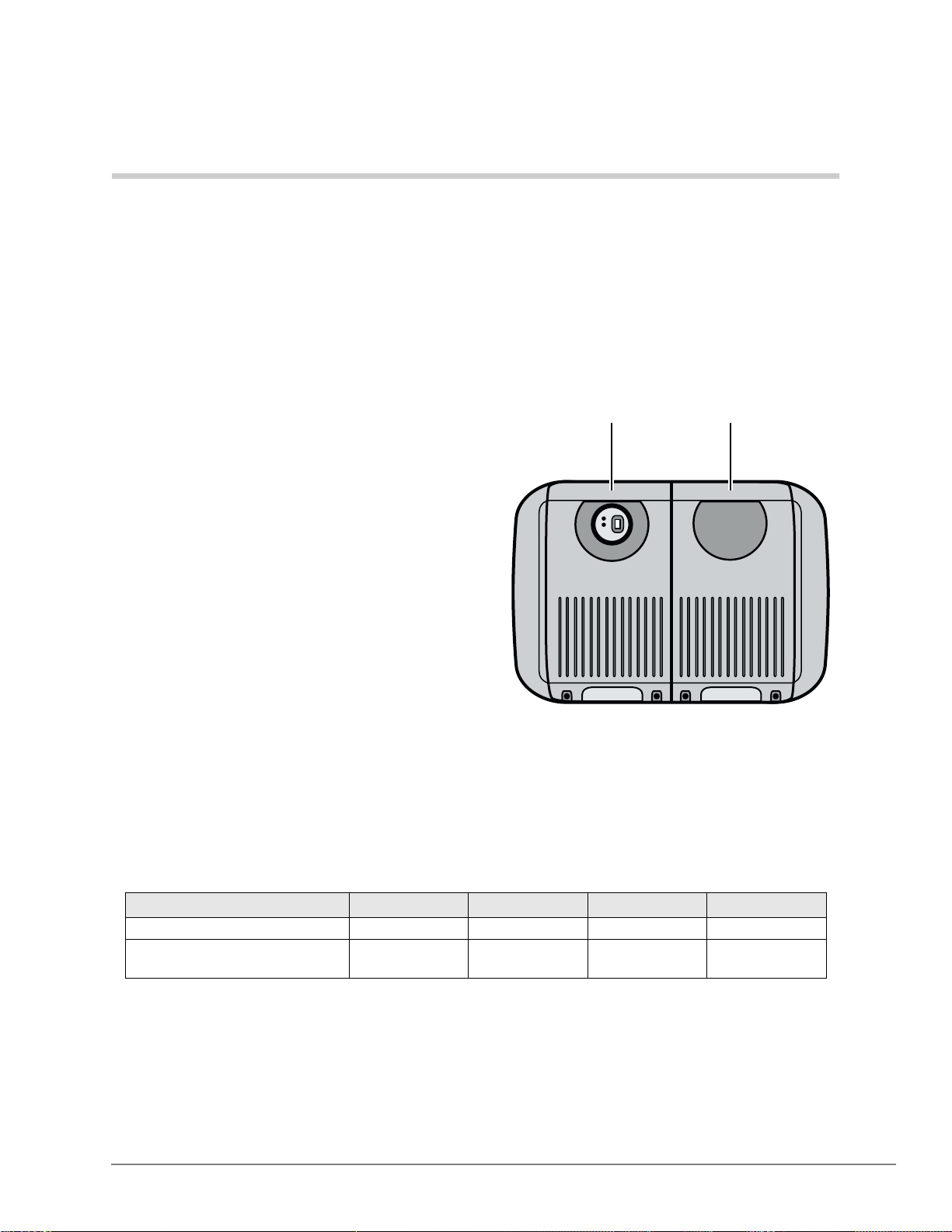
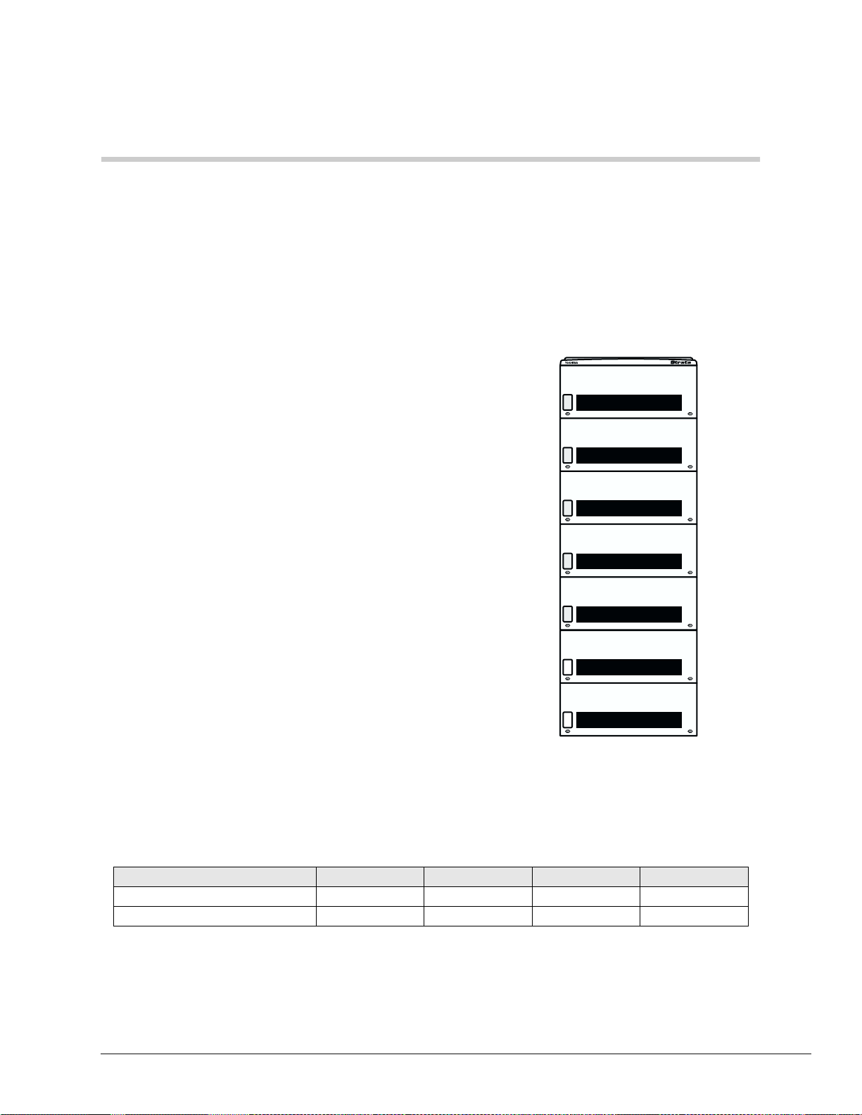
The Strata CTX100 is a compact system that
provides large system features (see
Base Expansion
Figure 1). It is designed for wall mounting and
occupies very little space.
The CTX100 basic pro cessor can be configured
with a one or two cabinet system. A single
(Base) cabinet system supports a combination
of up to 64 Central Office (CO) lines and
stations, while a two (Base and Expansion)
cabinet system can support up to 112 CO lines
and stations.
System line and st ation capac ity is expa nded by
adding CO line and station Printed Circuit
Boards (PCBs) into its universal slot
architecture.
The CTX100 easily connects to outside public
and private telephone lines. All of the
telephones (stations) tied to the system can
have direct access to each other, as well as to
Figure 1 CTX100 Base/Expansion
Cabinets
5976
the public and private network.
Each CTX100 system has a Base Cabine t with one opt ional Expansi on Cabi net. All line s, sta tions ,
and options are tied together through the cabinets. The overall weight and dimensions of the
CTX100 cabinets are shown in Table 1.
Table 1 CTX100 Cabinet Specifications
Cabinet
Base Cabinet (CHSUB112) 19.4 lbs. 14.6 in. 11.9 in. 10.2 in.
Base + Expansion Cabinet
(CHSUE1 12)
1. Weight includes the processor PCB in the Base Cabinet and four universal PCBs in each cabinet.
Strata CTX General Description 11/02 1
1
Weight
34.6 lbs. 14.6 in. 19.9 in. 10.2 in.
Height Width Depth
Page 16

Strata CTX100 Overview
CTX100 Processor
CTX100 Processor
The system operates with one processor circuit board (ACTU) that installs in a dedicated slot of
the Base Cabinet. The ACTU processor incorporates the following hard ware features:
CPU/Memory
The CTX100 uses a high-speed, 32-bit, RISC processor, Dynamic Random Access Memory
(DRAM) working memory, Static Random Access Memory (SRAM) wi th lithium battery for
memory back-up, and flash program memory.
Large Scale Integrated (LSI) Circuits
The processor has LSI circuits that support the following:
• 16 DTMF receivers – requires ARCS and, for five or more DTMF receivers, requires
appropriate licenses. See “CTX100 License Control” on page 4.
• 16 Busy Tone (BT) detectors for Auto Busy Redial (ABR) – requires ARCS.
• 64 built-in conference circuits (see Table 7 on page 13 for more information).
• Built-in, adjustable, digital volum e PAD technology enables audio volume to be ad justed in
eight steps to compensate for conference and/or CO line network losses.
Memory Protection Battery
If commercial AC power is lost or if a system is moved or stored without power, the processor has
an on-board battery th at protec ts data an d the cus tomer’s programme d configura tion from memory
loss. This in formation will be mainta ined in a powerless system for at least six years.
Relay Control Interface
An on-board terminal strip provides an interface to a normally open relay contact which can be
programmed to control a Night Bell, door lock or to mute BGM during an external page.
External Page Interface
A 600 ohm RCA jack is built into the processor to interface with a Toshiba External Amplified
Speaker (HESB) or a customer-supplied page amplifier and speaker(s) for external paging, night
ring over external page, and external BGM applications.
Music-on-hold/Background Music Interface
A 600-ohm RCA jack and volume controls are built into the processor to interface with Music-onhold and/or Background Music (BGM) sources (one of the jacks is for future use). With the
CTX100, you can have up to 15 MOH/BGM source interfaces by adding:
• Up to two BIOU PCBs, each provides three MOH/BGM input sources
• An RSTU PCB that provides up to eight MOH/BGM input sources
SmartMedia Memory
The processor has an on-board SmartMediaTM memory card slot. A SmartMedia flash memory
card can be inserted into the slot to backup and restore customer program data. It also makes it
easy to upload operating system data for software upgrades and is used for maintenance functions
(see “System Fault Finding and Diagnostics” on page 66 for more details).
2 Strata CTX General Description 11/02
Page 17
CTX100 Processo r Optional Subassemblies
Optional subassemblies can be atta ched to the ACTU pr ocesso r to provid e addition al features . The
subassemblies are:
• AMDS (Modem) – Provides a 33.6Kbps/V.34 modem for point-to-point local or remote
connection to the CTX WinAdmin administration PC.
• ARCS (DTMF Receiver/Busy Tone Detector) – Provides 16 DTMF receivers maximum and
16 Auto Busy Redial (ABR), Busy Tone detectors maximum.
• AETS (Ethernet LAN Interface) – Provides one 10baseT Ethernet circuit with an RJ45
connector for CTI Open Architecture applications, CTX Attendant Console, ACD Server,
Toshiba Proprietary Voice Mail integration and system administration connection (including
local and rem ote CTX WinAdmin).
• BSIS (Serial Port In ter fac e) – Provides up to two RS-232 inte rface ports for SMDR interface
to Call Accounting devices, SMDI or Toshiba Proprietary interface to Voice Mail devices, and
two future applications.
CTX100 Cabinet Slots
Strata CTX100 Overview
CTX100 Cabinet Slots
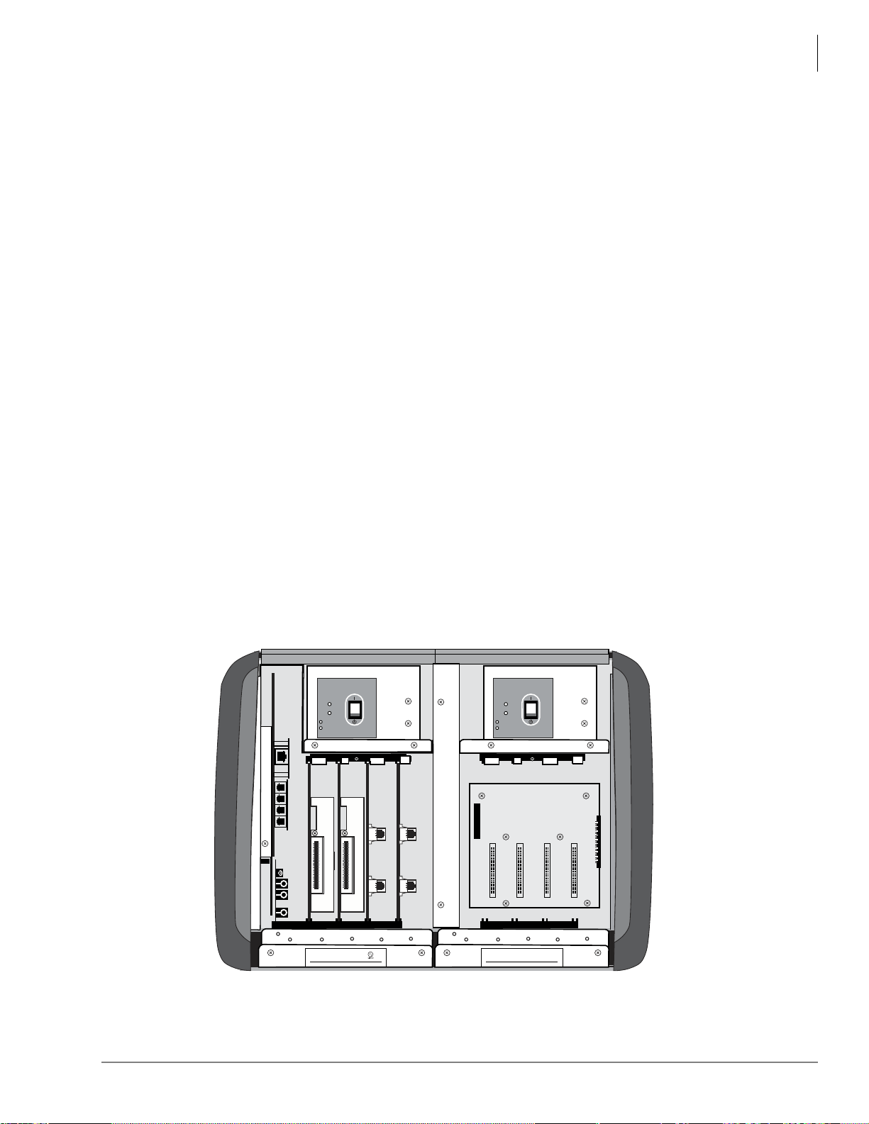
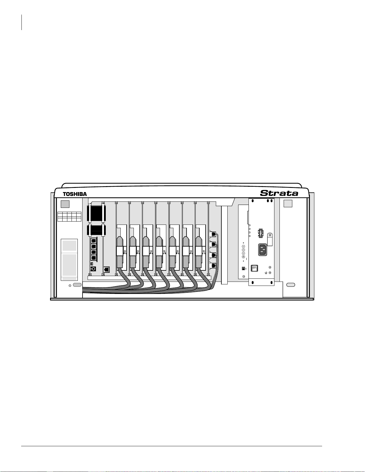
Base Cabinet
The Base Cabinet has one dedicated slot used for the system processor PCB and four universal
slots (S101~S104), that can accommodate station, line or option PCBs. It also houses a power
supply that is packaged with the cabinet.
Expansion Cabinets
One expansion cabinet provides four universal PCB slots (S105~S108) that can accommodate
station, line or option PCBs. It also houses a power supply that is packaged with the cabinet.
DC POWER
DC
AC
DC POWER
DC
AC
TOSHIBA
AMAUE1A
S101 S102 S103 S104 S105 S106 S107 S108
T
O
S
H
D
I
G
I
T
A
L
B
M
O
D
E
L
C
Strata CTX100
T
O
S
H
IBA
C
B
IA
U
S
I
N
E
S
S
T
E
L
E
P
H
S
U
B
1
1
2
A
V
1
I
N
P
ORP
ORAT
I
ON
49L7
H
O
N
E
S
Y
S
CUS
T
E
M
E88891
A
.
N
O
R
10062
TIM
U
T
:
1
2
0
V
a
c
6
0
H
z
1
.
8
A
MA
D
E
I
N
MAL
AY
S
I
A
Z
CP
T
O
S
H
D
I
G
I
T
A
L
B
M
O
D
E
L
C
Strata CTX100
T
O
S
H
IBA
C
B
IA
U
S
IN
E
S
S
T
E
L
E
P
H
O
N
E
S
Y
S
T
E
M
H
S
U
B
1
1
2
A
V
1
A
.
N
O
R
100
39
I
N
P
U
T
:
1
2
0
V
a
c
6
0
H
z
1
.
8
A
ORP
ORAT
I
ON
MA
D
E
I
N
MAL
AY
S
I
A
Z
CP
6576
Figure 2 Base and Expansion Cabinet Interior
Strata CTX General Description 11/02 3
Page 18

Strata CTX100 Overview
CTX100 License Control
CTX100 License Control
The system size and feature capability is controlled using a software License Key Code. This key
code is obtained from Toshiba Internet FYI during the ordering process and is installed onto the
system processor via Strata CTX WinAdmin. Processor license codes activate system hardware
capacities in the follow ing increments.
• The first 32 line/station ports do not require a license. Each additional set of four line/station
ports requires one LIC100-4 PORTS license (maximum of 112 ports).
• The optional DTMF receiv er circ uit (A RCS) provide s 16 DTMF rece iver har dware cir cuits an d
16 ABR circuits. The first four DTMF circuits and all ABR circuits do not require a license.
Each additional set of four DTMF receiver circuits requires one LIC100-4 DTMF license
(maximum of 16 DTMF circuits).
Note DTMF tone receiver circuits are required for standard telephones, Voice Mail DTMF
integration, Tie, DID and DNIS line service.
• The optional RS-232 serial port interface (BSIS) provides two circuits to interface with SMDI
or Toshiba Proprietary Voice Mail integration, Call Accounting SMDR, and two fo r future
applications. The first circuit does not require a license, but circuits two through four each
require one LIC100-SER PORT license.
Licensed Software Options
Some software options are activated with license codes. The following software options require a
license:
• Each CTX system (node) in a Strata Net QSIG Network requires one LIC100-QSIG NET
license. A maximum of four serial network nodes are allowed in any one serial chain in the
network topology.
• The optional AETS PCB provides hardware LAN interface for all CTI Open Architecture
applications. Each individual CTI Open Architecture application (future) requires one LIC100CSTA AP license (maximum nine).
4 Strata CTX General Description 11/02
Page 19
Strata CTX670 Overview 2
The Strata CTX670 system provides sophisticated
telecommunication features in a modular system
designed for growth. Its universal slot architecture
enables you to select the combination of Central Office
(CO) lines, stations, and per i pher al options that best suit
your needs.
The CTX670 basic processor can be configured for
smaller sy stems as a one or two cabi net system w i th a
capacity of up to 192 CO lines an d st ati ons combined. It
can expand to support up to seven cabinets with a
capacity of up to 672 CO lines and stations combined
(see Figure 3).
System line and station capacity is expanded by adding
processor expansion Printed Circuit Boards (PCBs),
cabinets and line/station PCBs.
The CTX670 easily connects to outside public and
private telephone lines. All of the telephones (stations)
tied to the system can have direc t acces s to eac h other as
well as to the public and private network.
The Base Cabinet and optional Expansion Cabinets are
the building blocks of the system. Each system has a
Base Cabinet, and can have from one to six Expansion
Cabinets. All lines , statio ns, and option s are tied together
through the cabinets.
Figure 3 CTX 670 Base/
Expansion Cabinets
5398
The overall weight and dimensions of the CTX670
cabinets are shown in Table 2.
Table 2 CTX670 Cabinet Specifications
Cabinet Weight Height Width Depth
Base Cabinet (CHSUB672) 31 lbs. 11.625 in. 26.5 in. 10.3 in.
Expansion Cabinet (CHSUE672) 29 lbs. 9.75 in. 26.5 in. 10.3 in.
Strata CTX General Description 11/02 5
Page 20

Strata CTX670 Overview
CTX670 Processor PCBs
CTX670 Processor PCBs
The system operates with one set of processor PCBs (BECU/BBCU) that install in dedica ted slot s
of the Base Cabinet. The BECU/BBCU processor incorporates the following on-board hardware
features:
CPU/Memory
The CTX670 uses a high-speed, 32-bit, Reduced Instruction Set Computing (RISC) processor,
Dynamic Random Access Memory (DRAM) working memory, Static Random Access Memory
(SRAM) with lithium battery for back-up memory, and flash prog ram memory.
Large-scale Integrated (LSI) circuits
The processor has LSI circuits that support the following:
• 16 built-in DTMF receivers; 32 available using the BEXS. For five or more DTMF receivers,
appropriate licenses are required. See “CTX670 License Control” on page 7.
• 16 built-in Busy Tone (BT) detectors for Auto Busy Redial (ABR); 32 available using the
BEXS
• 64 built-in conference circui ts; up to 96 conferenc e circuits are avail able usi ng the BEXS. (See
Table 7 on page 13 for more information).
• Built-in, adjustable, digital volum e PAD technology enables audio volume to be ad justed in
eight steps to compensate for conference and/or CO line network losses.
Memory Protection Battery
If commercial AC power is lost or if a system is moved or stored without power, the processor has
an internal battery that protects data and the customer’s programmed configuration from memory
loss. This in formation will be mainta ined in a powerless system for at least six years.
Music-on-hold/Background Music Interface
An RCA jack and volume control are built into the processor to interface with a Music-on-hold
and/ or Background Music source. With the CTX670, you can have up to 15 MOH/BGM sources
by adding:
• Up to two BIOU PCBs, each provides three MOH/BGM input sources
• An RSTU PCB that provides up to eight MOH/BGM input sources
SmartMedia Memory
The processor has an on-board SmartMedia card slot. A SmartMedia flash memory card can be
inserted to backup and restore customer program data. It also makes it easy to upload operating
system data for software upgrades and is used for maintenance functions (see “System Fault
Finding and Diagnostics” on page 66 for more details).
6 Strata CTX General Description 11/02
Page 21

Strata CTX670 Overview
CTX670 License Control
Network Interface
The processor has an on-board Ethernet 10Base-T Ethernet circuit for connection to Open
Architecture Computer Telephony Interface (CTI) applications. This provides extensive call
control and telephone support for CTI applications. The Ethernet Network Interface Card (NIC)
port also enables connection to the following:
• CTX Attendant Console
• ACD server
• Local and Remote CTX WinAdmin PC
• Soft Key Control of Voice Mail features
Maintenance Modem
A built-in maintenance modem (33.6Kbps/V.34) on the processor can provide point -t o-point local
or remote connection to the CTX WinAdmin administration software.
CTX670 Processor P CB Subassemblies
Subassemblies can be added to the processor PCBs to enable system expansion and provide
additional features. The subassemblies are:
• BEXS and BBMS expansion PCBs mount onto the processor PCBs to provide increased port
capacity, from Basic (192 ports) to Expanded (672 ports). The BEXS provides switching
capacity, and the BBMS provides memory capacity. For Basic and Expanded capacities of
stations, lines and features, see Tables 3~7. To expand the system, both subassemblies must be
installed.
• BSIS interface PCB which attaches to the BECU to pr ovide up to four RS-232 interface port s
for SMDR Call Accounting and SMDI or Toshiba Proprietary Voice Mail interface.
See Table 3 on page 11 for the number of cabinets and universal PCB slots for the Basic and
Expanded systems.
CTX670 License Control
The system size and feature capability is controlled using a software License Key Code. This key
code is obtained from the Toshiba Internet FYI site during the ordering process and is installed
onto the system processor via Strata CTX WinAdmin. Processor license codes activate system
hardware capacities in the following increments.
• The first 64 line/station ports do not require a license. Each additional set of four line/station
ports requires one LIC670-4 PORTS license (maximum of 672 ports).
• The on-board DTMF receiver circuit provides up to 32 DTMF receiver hardware circuits. The
first four DTMF circuits do not require a license. Each additional set of four DTMF receiver
circuits requires one LIC670-4 DTMF license (max. total of 32 DTMF circuits).
Note DTMF tone receiver circuits are required for standard telephones, Voice Mail DTMF
integration, Tie, DID and DNIS line service.
• The optional RS-232 serial port interface (BSIS) provides two circuits to interface with Voice
Mail, SMDI or Toshiba Proprietary Voice Mail integration, Call Accounting SMDR, and two
for future applica tions . The first circu it does not requir e a lice nse , but circ uits t wo thr ough four
each require one LIC670-SER PORT license.
Strata CTX General Description 11/02 7
Page 22
Strata CTX670 Overview
CTX670 Cabinet Slots
Licensed Software Options
Some software options are activated with license codes. The following software options require a
license:
• Each CTX system (node) in a Strata Net QSIG Network requires one LIC670-QSIG NET
license. A maximum of four serial network nodes are allowed in any one serial chain in the
network topology.
• Each individual CTI Open Architecture application requires one LIC670-CSTA AP license
(maximum nine).
CTX670 Cabinet Slots
Base Cabinet
The Base Cabinet has two dedicated slots used for the system processor PCBs and eight universal
slots, labeled “S101~S108,” tha t can accommodat e station, CO line or option PCBs (see Figure 4).
It also hous es a power supply.
B101 B102 S101 S102 S103
S104 S105 S106 S107
S108
B101 B102 S101 S102 S103 S104 S105 S106 S107 S108
Figure 4 Base Cabinet Interior
DC OUT
-24V1
-24V2
BATT
+
-24V3
-
-24V4
POW
+5V
AC IN
-5V
P.F.
POWER
RESET
ON
EXP
BASE
OFF
FG
5002
5466
8 Strata CTX General Description 11/02
Page 23
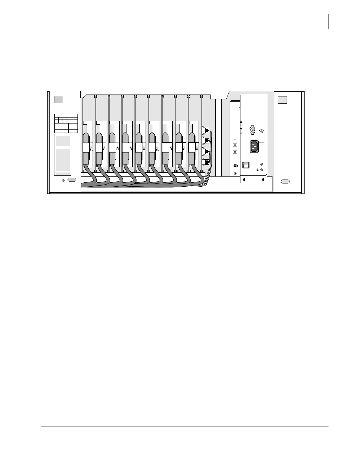
Strata CTX670 Overview
CTX670 Remote Expansion Cabinet
Expansion Cabinets
One to six Expansion Cabinets can be added to increase the system station and CO line capacity.
Each expansion cabinet provides 10 slots (S_01~S_10). Figure 5 shows an Expansion Cabinet.
Refer to the following section for cabinet slot and station/line capacities. Tables 4 and 5 show the
number of stations and CO lines allowed when additional cabinets and PCBs are used.
DC OUT
CABINET NO.
2
34567
S_01 S_02 S_03 S_04 S_05
S_06 S_07 S_08 S_09 S_10
S_01 S_02 S_03 S_04 S_05 S_06 S_07 S_08 S_09 S_10
DC OUT
-27V1
-27V1
-27V2
-27V2
AC IN
BATT
+
-27V3
+
-27V3
-
-
-27V4
-27V4
POW
POW
+5V
AC IN
+5V
AC IN
-5V
-5V
P.F.
P.F.
POWER
RESET
POWER
RESET
ON
ON
EXP
EXP
BASE
BASE
OFF
OFF
FG
FG
5002
5002
Figure 5 Expansion Cabinet Interior
CTX670 Remote Expansion Cabinet
A CTX670 Expansion Cabinet can be located up to three kilometers (1.86 miles) from its Base
Cabinet. Remote Expansion Cabinets are enabled by the RRCU PCB. One RRCU connects to up
to two ribbon-type Data Cables and applies the inter-cabinet signal to a multi-mode fiber-optic
pair. One fiber pair can support one or two expansion cabinets in one remote location using one
RRCU in the Base Cabinet and another in the Remote Expansion Cabinet.
The CTX670 Base Cabinet supports up to six Remote Expansion Cabinets (at least one RRCU
PCB is required for each rem ote location).
Remote cabinets support the BIOU for external Page Zones, Night Bell, etc., and all CO line and
trunk interface PCBs. Network clock synchronization can only be derived from digital trunks
installed in the Base Cabinet (Maste r) location.
5003
Strata CTX General Description 11/02 9
Page 24

Strata CTX670 Overview
CTX670 Remote Expansion Cabinet
10 Strata CTX General Description 11/02
Page 25
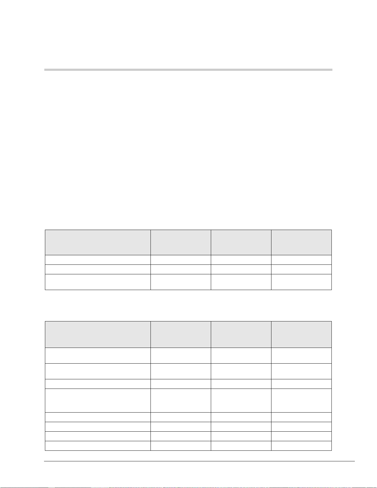
Capacities 3
This chapter contains Strata CTX100 and CTX670 capacities for stations and peripherals, CO
lines, station buttons and system features. All tables apply to both systems unless otherwise noted.
System Capacities
Important! The maximum capacities listed for the CTX100 in Tables 3~7 are based on an
expanded CTX100 (Base + Expansion cabinet).
Table 3 Cabinet and Slot Capacities
Cabinets/Slots/Ports CTX100
Cabinets 1 or 2 1 to 2 1 to 7
Universal slots 4 or 8 8 or 18 8 to 68
Maximum capacity of ports
(lines + stations)
112 192 672
CTX670
Basic Processor
BBCU + BECU
CTX670
Expanded Processor
BBCU + BECU
+ BEXS + BBMS
Table 4 Station/Peripherals System Capacities
Stations
Add-on modules (DADM3 020) per Base
1
Cabinet
Add-on modules (DADM3 020) per
Expansion Cabinet
CTX Attendant consoles 2 2 4
DKT3000- and 2000-se ries DKTs
DKT2104-CT Cordless Telephone
DKT2004-CT Cordless Telephone
Door locks 4 5 10
Door phone control boxes (DDCB) 2 3 8
1
1
1
1
CTX100
Base & Expansion
30 DKTs with 1 ADM
23 DKTs with 2 ADMs
31 DKTs with 1 ADM
24 DKTs with 2 ADMs
72/system
(40 Base Cabinet)
(40/Expan. Cab.)
72 160 560
72 160 560
CTX670
Basic Processor
BBCU + BECU
55 DKTs with 1 ADM
43 DKTs with 2 ADMs
57 DKTs with 1 ADM
45 DKTs with 2 ADMs
152/system
(72 Base Cabinet)
(80/Expan. Cab.)
CTX670
Expanded Processor
BBCU + BECU +
BEXS + BBMS
55 DKTs with 1 ADM
43 DKTs with 2 ADMs
57 DKTs with 1 ADM
45 DKTs with 2 ADMs
552/system
(72 Base Cabinet)
(80/Expan. Cab.)
Strata CTX General Description 11/02 11
Page 26
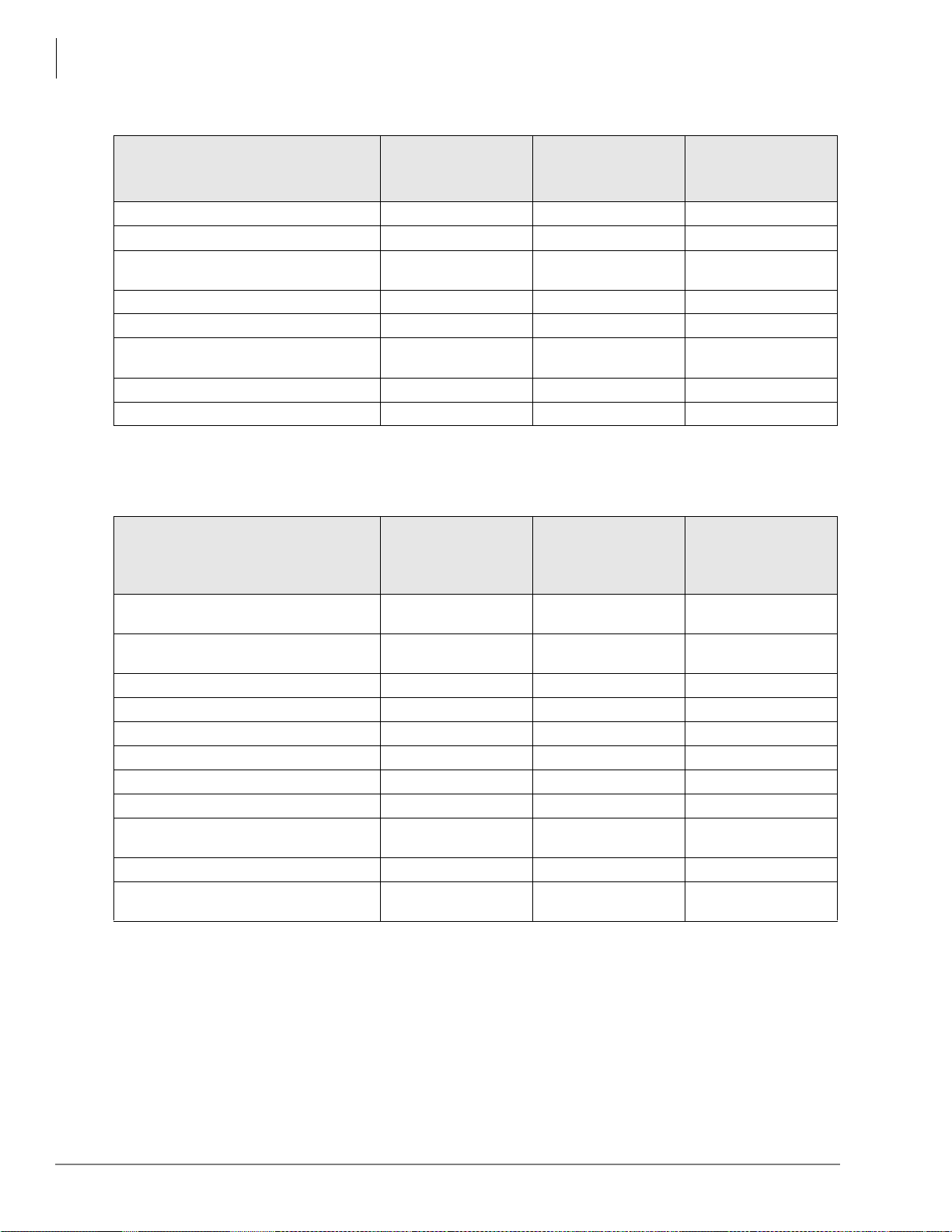
Capacities
System Capacities
Table 4 Station/Peripherals System Capacities (continued)
CTX670
Expanded Processor
BBCU + BECU +
BEXS + BBMS
Stations
CTX100
Base & Expansion
CTX670
Basic Processor
BBCU + BECU
Door phones 6 9 24
DSS consoles (DDSS) 3 5 16
ISDN BRI station circuits TE-1 and TA
(2B+D per cir c uit)
12 28 96
Off-premise stations 72 160 560
BPCI used for TAPI only: per cabinet
1
T otal St ations (Digital/Analog/ISDN BRI B
channel com bined)
35 66 66
72 160 560
Standard stations 64 160 560
Calls existing at the same time 56 96 366
1. Limit is based on cabinet Power Factor (PF).
Table 5 Line Capacities and Universal PCB Slots
CTX670
Expanded
Processor
BBCU + BECU +
BEXS + BBMS
Lines
CO lines – loop start
(analog - 8 lines/slot)
CO lines – ground start
(analog - 4 lines/slot)
CTX100
Base & Expansion
64 96 264
32 72 264
CTX670
Basic
Processor
BBCU + BECU
DID lines (analog - 4 lines/s lo t) 32 72 264
Tie lines (analog - 4 lines/slot) 32 72 264
VoIP lines (4 lines/slot)
T1 lines (DS-1)
ISDN BRI B channel lines
ISDN PRI B channel lines
1
2
3
4
Total lines (Analog, T1, ISDN BRI and
PRI B channels combined)
82020
64 96 264
64 96 256
48 96 264
64 96 264
Channel Groups 32 48 128
Number of groups with Group CO Line
buttons
1. Capacity is limited by FCC, Part 15, ElectroMagnetic Compatibility (EMC) restrictions.
2. T1 lines can be loop start, ground start, Tie or DID (maximum 24 lines per unit, any type or combination).
3. BRI lines provide CO line services, including Caller ID, DID and Direct Inward Lines (DIL).
4. PRI lines provide CO line services, including QSIG Networking, Calling Party Number/Name, DID, Tie, POTS, FX and DIT.
32 50 128
12 Strata CTX General Description 11/02
Page 27
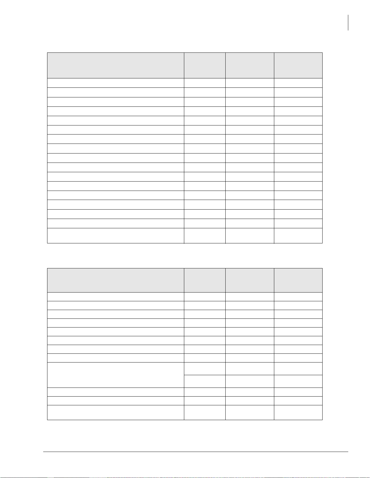
Table 6 Station Buttons
Capacities
System Capacities
CTX670 Expanded
Processor
BBCU + BECU
+ BEXS + BBMS
Station Buttons per System
CTX100 Base &
Expansion
CTX670
Basic Processor
BBCU + BECU
Call Forward, Personal CF Buttons 72 160 560
CO Line Buttons 64 96 264
Group CO Line Buttons 64 96 264
Pooled CO Line Buttons 32 50 128
CO Group and Pooled Line But t ons 64 96 264
Station Loop Buttons
Door Unlock Buttons
8
4
15 50
816
Flexible Telephone Buttons 1600 3500 12000
Line Buttons in use at the same tim e 1440 3200 3200
Message Waiting Registration (D Ns with MW) 130 230 800
Multiple Appearances of DNs on Telephones 2000 4000 12000
Night Transfer Buttons 2 4 8
One Touch Buttons 800 1750 6000
Primary Directory Numbers [PDNs] per system 72
Phantom Directory Numbers [PhDNs] per system 288
[PhDNs] with Messag e Waiting Indication LED 18
ISDN DNs
96
(8 DNs/station)
160 560
640 2240
38 128
224
(8 DNs/station)
768
(8 DNs/station)
Table 7 System Feature Capacities
Features
Pilot DNs
Advisory LCD Messages (Set on a Telephone)
Advisory LCD Messages Lists (per System)
Attendant Groups
Call Accounting SMDR Interface
1
Call Forward, System CF Patter ns
Call Park Orbits (General)
Call Park Orbits (Individual )
Caller ID/ANI/CNIS Numbers stored (Call History r ecords)
CO Line Groups - Incoming Line Groups (ILG)
CO Line Groups - Outgoing Line Groups (OLG)
Outgoing Line Groups (OLG) Members per s yst em
(Tru nks + ISDN Line Service Ind ex)
CTX100 Base &
Expansion
CTX670
Basic Processor
BBCU + BECU
CTX670 Expanded
Processor
BBCU + BECU
+ BEXS + BBMS
100 200 256
11 1
10 10 10
11 1
11 1
410 32
14 32 64
56 96 336
Up to 100/
station
Up to 660/
system
Up to 100/station Up to 100/station
Up to 1000/system Up to 2000/system
32 50 128
32 50 128
96 144 392
Strata CTX General Description 11/02 13
Page 28

Capacities
System Capacities
Table 7 System Feature Capacities (continued)
CTX670 Expanded
Processor
BBCU + BECU
+ BEXS + BBMS
Features
CTX100 Base &
Expansion
CTX670
Basic Processor
BBCU + BECU
Conference Circuits 64 64 96
Conferencing (thre e- parties simultaneousl y)
Conferencing (eigh t- pa rt ies simultaneously)
Conference Party typ es ( up t o 8 t ot al line s + st at ions)
Two-CO Line Conferencing – simultaneously
(Two party only, no telephone or VM port)
2
2
2
20 21 21
88 12
6 lines max.
8 stations max.
6 lines max.
8 stations max.
6 lines max.
8 stations max.
32 48 132
Conference/Line Volume Adjustment (PAD) Groups 6 10 32
DID Numbers for Calling Number Identification/system 225 500 1000
DNIS/DID Network Ro ut ing N umbers 200 400 1000
DNIS/DID Number s 450 1000 2000
DTMF Receivers
3
16 16 32
E911 Groups 8 8 8
Emergency Call Groups 8 8 8
Hunt Groups (Serial/ Ci rc ul ar /Distributed combined ) 90 200 640
Hunt Group Size (DNs per gro up) 72 160 560
Hunt Group Stations (per system) 360 800 2800
ISDN DNs 96 224 768
ISDN Line Service Index es 32 48 128
Night Bell Control Relay
4
Night Transfer Control Relay
4
11 1
11 1
Off-hook Call Announce Handsets (simultaneous) 20 21 31
Off-hook Call Announce to Telephone Speakers
Page Mute External BGM Control Relay
Page Zone Relays
4
4
5
72 112 352
11 1
88 8
Page Groups (Telephones with or without External Zones) 4 8 16
Paging – (Group Paging – simultaneous stations paged) 72 120 120
Pickup Groups 5 10 32
Ring Tones (External Call Ring Tones for digital phones) 4 4 4
Ring Tones (Internal Call Ring Tones for digital phones) 1 1 1
Speed Dial - Station SD num ber s pe r s yst em
6
1080 2400 5600
Speed Dial - System SD num bers per system 800 800 800
Stratagy DK Voice Mail Systems per system 1 1 1
Tenants 1 1 1
Destination Restriction Level (DRL) Classes 16 16 16
Verified Account Codes 135 300 1000
Voice Mail SMDI Interface
1. SMDI and SMDR require BSIS serial port interface.
2. Conference circuits are used dynamically, so the maximum number of simultaneous conferences is affected by the number of
conference members in each conference. The total number of members in simultaneous conferences cannot exceed the total
number of conference circuits. Each conference can have up to eight members.
3. DTMF receivers are required for standard touch tone telephones, voice mail integration, Tie, DID and DISA lines.
4. An option BIOU is required for up to four zone page relays and four control relays on the CTX100 and CTX670. One control
relay is provided on board the CTX100 processor.
5. Speaker OCA capacity is determined by 2B channel slot availability and power supply. Requires BVSU option in telephone.
6. Up to 100 Station SD numbers, allocated in increments of 10, can be programmed per station.
1
11 1
14 Strata CTX General Description 11/02
Page 29
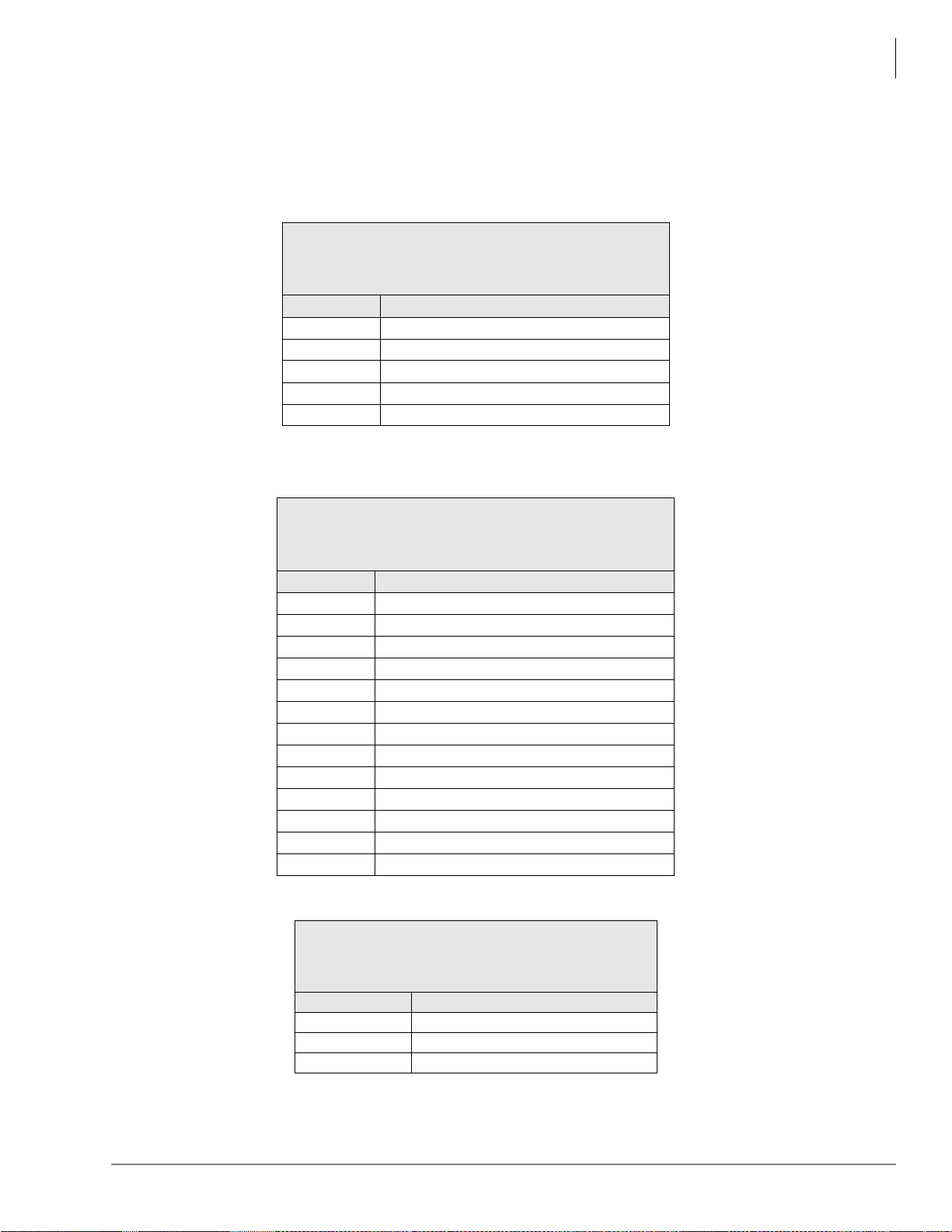
CTX100 Maximum Capacity Configuration Examples
CTX100 Maximum Capacity Configuration
Examples
Table 8 CTX100 Base Cabinet with Digital Telephones and Loop Start Line With or Without Caller ID
4 Universal Slots
40 Stations (Max.)
24 CO lines (Max.)
44 Stations + Analog loop start lines combined (Max.)
Stations Analog loop start lines
40 4 (none can have Caller ID)
32 8 (all can have Caller ID)
32 16 (none can have Caller ID)
16 16 (8 can have Caller ID)
1
24
1. Using ADKU.
Table 9 CTX100 Base and Expansion Cabinet with Analog Loop Start Lines
8 (none can have Caller ID)
Capacities
8 Universal Slots
72 Stations (Max.)
56 CO lines (Max.)
92 Stations + Analog Loop Start Lines combined (Max.)
Stations Analog loop start lines
72 20 (none can have Caller ID)
72 16 (8 can have Caller ID)
64 32 (none can have Caller ID)
64 24 (8 can have Caller ID)
64 16 (all can have Caller ID)
48 40 (none with Caller ID)
48 32 (8 can have Caller ID)
48 24 (16 can have Caller ID)
32 48 (none can have Caller ID)
32 40 (8 can have Caller ID)
32 32(16 can have Caller ID)
32 24 (24 can have Caller ID)
16 32 (24 can have Caller ID)
Table 10 CTX100 Base Only: Digital Telephones and T1 and/or PRI lines
4 Universal Slots
40 Stations (Max.)
48 lines (Max.)
64 Stations + T1 and/or PRI lines combined (Max.)
Stations T1 and/or PRI lines
40 24/23
32 40/40
16 48/46
Strata CTX General Description 11/02 15
Page 30
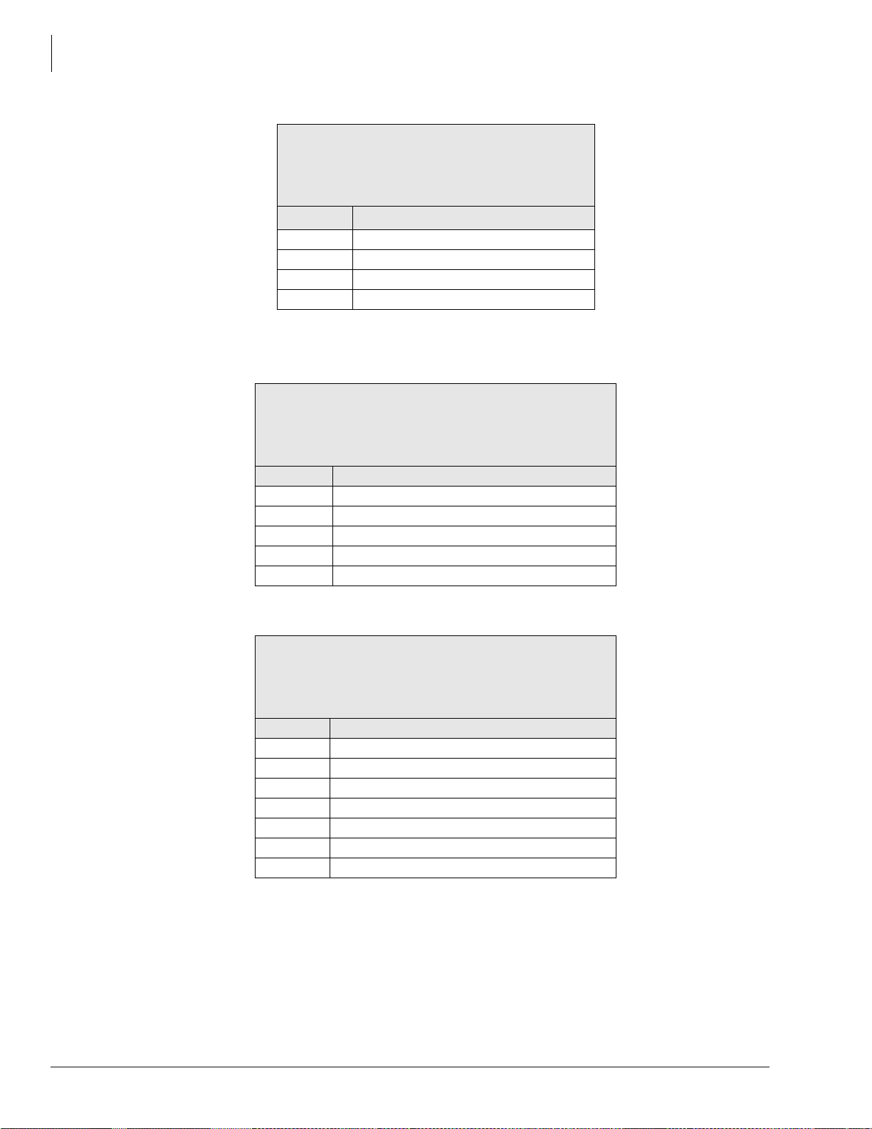
Capacities
CTX100 Maximum Capacity Configuration Examples
Table 11 CTX100 Base and Expansion Digital Telephones and with T1 and/or PRI lines
8 Universal Slots
72 Stations (Max.)
64 lines (Max.)
112 Stations + T1 and/or PRI lines combined
(Max.)
Stations
72 40/40
64 48/48
56 56/48
48 64/48
1. PRI lines are limited to 48B channels.
Table 12 CTX100 Base Cabinet Only with Analog Tie, DID and /or Ground Start Lines
40 Stations + Analog Tie, DID, Ground Start Lines
Stations Analog Tie, DID, and/or Ground Start Lines
40 4 line (Ground Start only)
32 8 lines (4 Tie/DID max.).
24 8 line any type
16 12 line any type
0 16 line any type
T1 and/or PRI lines1
4 Universal Slots
40 Stations (Max.)
16 CO lines (Max.)
combined (Max.)
Table 13 CTX100 Base and Expansion Cabinet with Analog Tie, DID and/or Ground Start Lines
8 Universal Slots
72 Stations (Max.)
32 CO lines (Max.)
80 Stations + Analog Tie, DID and/or ground start Lines
combined (Max.)
Stations Analog Tie, DID, and/or Ground Start Lines
72 12 lines (4 Tie/DID max.)
64 16 lines (8 Tie/DID max.)
56 16 lines (12 Tie/DID max.)
48 16 lines any type
48 20 lines (16 Tie/DID max.)
32 24 lines any type
16 28 lines any type
16 Strata CTX General Description 11/02
Page 31

Universal Slot PCBs 4
Universal Printed Circuit Boards (P CBs) install ed in the Strata C TX100 or CTX670 cabine ts
provide interfaces for stations, lines, and peripherals. Each PCB measures 7.5 x 5.5 inches (190 x
140 mm) and mounts in the slot with a 44-pin backplane connector. PCB external connections to
station equipment are made to the Main Distribution Frame (MDF) using industry-standard
connectors.
Station, Line and Option PCBs
The PCBs are categorized as station, CO line or option PCBs (see Tables 14~16). Feature
subassemblies that plug onto a universal slot PCB, such as the Standard Telephone Interface
Subassembly (RSTS), are listed below the associated PCB. For further details, refer to the Strata
CTX I&M Manual.
Table 14 Station PCBs
Digital Telephone Interface Unit (ADKU) (CTX100 only)
Provides eight circuits for 3000 and/or 2000-series
digital telephones.
Digital Telephone Interface Unit (BDKU)
Provides eight circuits for 3000 and/or 2000-series
digital telephones (BDKU) + eight more with BDKS
(optional).
Digital Telephone Interface Subassembly (BDKS)
Provides eight additional circuits for 3000 and/or 2000series digital telephones. Attaches to BDKU. One per
BDKU. Do not use BDKS for Speaker OCA
telephones, except in slot 103 of the CTX100.
Interface Options: Provides the same interface options
as the BDKU (see below), but does not support BDKS.
Compatible only with CTX100.
Interface Options: Digital telephones (with or without
BHEU, BPCI, BVSU, DADMs, or digital cordless
telephone). Supports BDKS.
Stand-alone digital cordless telephone
DDSS console
BATI
DDCB
Supports large LCD (DKT3014) features.
Interface Options: Same as BDKU. Not compatible with
ADKU or PDKU.
Strata CTX General Description 11/02 17
Page 32

Universal Slot PCBs
Station, Line and Option PCBs
Table 14 Station PCBs (continued)
Digital Telephone Interface Unit (PDKU2)
Provides eight digital telephone circuits (2000-series
phones only. Do not use the PDKU for 3000-series
digital telephones.). LCD display is only 16 characters
6SGLDO
wide and the
Internet Protocol (IP) Interface Unit (BVPU)
Provides four VoIP Circuits as E&M Tie lines
One 10Base-T port
One RS-232 maintenance po rt
H.323 standard for Voice over Internet Protocol (VoIP).
Digital/Standard Telephone Interface Unit (RDSU)
Without RSTS, provides:
Two standard telephone/
Four digital telephone circuits (2000-series phones
only).
With RSTS, provides:
Four standard telephone/
Four digital telephone circuits (2000-series phones
only).
Standard Telephone Interface Unit (RSTU3)
Provides eight standard telephone circuits. Stutter dial
tone is provided for Message Waiting audible
indication.
Standard Telephone Subassembly (RSTS)
Attaches to RDSU. Provides two additional standard
telephone circuits. One maximum per RDSU.
-48 Volt Supply Internal Option (R48S)
Attaches to RSTU and RDSU
48VDC circuit for up to eight standard telephone
circuits.
Stratagy DK
Provides two, four, six, or eight VM ports.
All of the above Stratagy DK sy ste ms us e eight station
ports of Strata CTX capacity.
button will not work.
Interface Options: Digital telephones (with or without
BHEU or HHEU, DVSU, DADMs, or digital cordless
telephone)
Stand-alone digital cordless telephone
DDSS console
DDCB
Does not support DKT3014-SDL features.
Interface Options: LAN, Internet, WAN.
Interface Options:
Digital – same as PDKU.
Standard – same as RSTU (standard Message Waiting
not available)
Interface Options:
Standard telephones
Voice ma il p orts
Off-premises stations
Other similar devices
Alternate BGM source
Auto Attendant digital announcer
Message Waiting lamp
Fax machines
ACD Announcer
Interface Options: Same as RSTU, exce pt no Mes sage
Waiting lamp.
Interface Options: Optionally interfaces to the RSTU
and RDSU to extend loop length of standard telephones
from 600 ohms to 1200 ohms. Required for OPS
operation.
18 Strata CTX General Description 11/02
Page 33

Table 15 CO Line PCBs
Caller ID Interface Unit (RCIU2)
Provides four Caller ID circuits.
With RCIS: eight circuits.
Interface Options:
Provides Caller ID LCD displ ay f or ana log l oop o r gr ound
start lines with Caller ID. Requires: RCOU, RCOS,
RGLU2 or PCOU. Not compatible with T1.
Caller ID Interface Subassembly (RCIS)
Same as RCIU2.
Attaches to the RCIU2.
Direct Inward Dialing Interface Unit (RDDU)
Provides four DID circuits. Interface Options:
DID analog lines.
Enhanced 911 CAMA Trunk Interface Unit (RMCU/RCMS)
E911 CAMA circuits. Provides up to four CAMA trunk
E911 analog CAMA trunks.
circuits. The RMCU/RCMS eliminates the need for
connection of adjunct terminal adapter equipment to
E911 CAMA trunks.
Requires one or two RCMS PCBs for two or four
CAMA lines respectively.
CAMA Trunk Subassembly (RCMS)
Same as RMCU.
RCMS attaches to RMCU. Provides two E911 CAMA
circuits.
Up to two RCMSs per RMCU for four CAMA lines max.
(One RCMS comes packaged with the RMCU.)
Ground/Loop Start Interface CO Line Interface Unit (RGLU2)
Provides four ground or loop start line circuits. Each
can be individually set for ground or loop start
operation.
Interface Options:
Analog loop or ground start analog lines.
ISDN S/T-type Basic Rate Interface Unit (RBSU)
Two ISDN BRI S/T point circuits (NT or TE). Each
Interface Options: Network and/or station side.
circuit is 2B+1D. (Host for the RBSS.)
Basic Rate Interface Subassembly (RBSS)
Interface Options: Station side only.
Attaches to attaches to RBSU. One RBSS
subassembly per RBSU.
Two ISDN BRI, S point circuits (2B+D each).
ISDN U-type Basic Rate Interface Unit (RBUU)
Provides two ISDN BRI, U point circuits (2B+D each).
Host for the RBUS.
Basic Rate Interface Subassembly (RBUS)
Interface Options: Network and/or station side. Network
side requi res a dealer-supplied NT1 interface.
Interface Options: Network and/or station side.
Attaches to attaches to RBUU. One RBUS
subassembly per RBUU.
Two ISDN BRI, U point circuits (2B+D each)
subassembly for the RBUU.
Universal Slot PCBs
Station, Line and Option PCBs
Strata CTX General Description 11/02 19
Page 34

Universal Slot PCBs
Station, Line and Option PCBs
Table 15 CO Line PCBs (continued)
ISDN Primary Rate Interface Unit (RPTU2)
Provides (1~8B + D), (1~16B + D), or (1~23B + D)
channels (lines), depends on system programming.
RPTU2 is required for QSIG Networking.
Loop Start CO Line Interface Unit (RCOU)
Provides four CO analog loop start line circuits.
With RCOS, provides eight CO analog loop start line
circuits.
Loop Start CO Line Interface Subassembly (RCOS)
Provides four additional Loop Start CO lines. One
RCOS subassembly per RCOU.
T1/DS-1 Interface Unit (RDTU2)
Provides T1 (DS1) Interface: 1~8, 1~16, or 1~24
channels (lines), depends on system programming.
Remote Expansion Cabinet Unit (RRCU)
Supports two CTX670 rem ote ca bin ets . 62 .5 m µ, m ult imode fiber.
Tie Line Unit (REMU2)
Provides four analog Tie line circuits. Interface Options:
Interface Options:
ISDN PRI
POTS
FX
Tie (senderized)
Tie (cut through)
OUTWATS (intra-LATA)
OUTWATS (inter-LATA)
InWATS
QSIG
Interface Options:
CO analog loop start lines
Same as RCOU.
Interface Options:
T1
Loop start lines
Ground start lines
Tie lines (wink or immediate)
DID/DOD lines (wink or immediate)
Remote cabinet not supported by main system reserve
power.
E&M Tie lines
Two- or four-wire transmission
Type I signaling
Type II signaling
Immediate start
Wink start
Table 16 Option PCBs
Option Interface Unit (BIOU) Interface Options:
Provides Paging output (600 ohm and three-watt amp),
four zone paging relays, three MOH interfaces and four
control relays (Night Transfer and BGM mute).
20 Strata CTX General Description 11/02
Page 35

Functional Block Diagrams
The Functional Block Diagrams show the PCBs and interface connectors used for connecting the
stations and peripherals (see Figures 6~9).
SMDR
Call Accounting
Stratagy ES
Voice Mail
For iES32/IVP8 VM port
connection, see Figure 9.
Remote CTX
WinAdmin PC
ACD
(CSTA)
Amplified Page Output (3 Watts)
Music Source: External Zone Page
Background Music
Door Lock Control Relay
Night Bell Control Relay
External Zone Page Relays (4 Zones)
Local CTX
WinAdmin
SMDI or Toshiba Proprietary
Integration
Toshiba Proprietary Soft Key LCD Link
Internet
MOH/BGM Jack
+Volume Control
25 Pair
Hub
or
LAN
MOH/BGM
RCA Jacks
Up to Four Programmable Serial (RS-232)
Port Modular Jacks Available
ACTU
(Optional)
RJ45
AETS
Ethernet
Interface
Relay Contact (Programmable)
RCA Jack (600 ohm Page Output)
(one or two per system)
Relay Contacts
Processor PCB
1
BSIS
1
AMDS
Remote Maintenance
Modem
1
1
ARCS
DTMF/ABR
Receivers
Interface PCB
BIOU
MOH/BGM
Volume Controls
License
1
Conference
SW with PAD
Smart Media
Maintenance
and
Customer
2
Database
Universal Slot PCBs
Functional Block Diagrams
Data and Speech Highway
External Page Amplifier (600 ohm Output)
BGM Mute Control Relay
Night Control Relay
Main Distribution
Frame (MDF)
APSU112
Cabinet
Power Supply
1
ABCS
Battery Charger
12V
Battery
12V
Battery
(2 or 4 Batteries)
ABTC - 3m Cable
1
Notes
Music Source 1: Background Music
and/or Music-on-hold
Music Source 2: Background Music
and/or Music-on-hold
Music Source 3: Background Music
and/or Music-on-hold
1. Optional.
2. License Control.
On this page, all equipment, except Stratagy ES,
connected to the system processor PCBs and
BIOU PCB is customer-supplied.
5991
Figure 6 CTX100 System Processor and Option Interface PCBs
Strata CTX General Description 11/02 21
Page 36

Universal Slot PCBs
Functional Block Diagrams
SMDR
Call Accounting
Up to Four Programmable Serial (RS-232)
Port Modular Jacks Available
BECU
Processor PCB
Stratagy ES
Voice Mail
For iES32/IVP8 VM port
connection, see Figure 9.
Remote CTX
WinAdmin PC
ACD
(CSTA)
Attendant
Console (see
Fig. 8 for BATI
connection)
Amplified Page Output (3 Watts)
Music Source: External Zone Page
Background Music
Door Lock Control Relay
Night Bell Control Relay
Internet
SMDI and Stratagy ES Integration
MOH/BGM Jack
+Volume Control
Toshiba Proprietary Soft Key LCD Link
RJ45
Hub
or
LAN
Local CTX
WinAdmin
25 Pair
MOH/BGM
RCA Jacks
BSIS
(Optional)
Remote Maintenance
Modem (Built-In)
DTMF/ABR
Receivers( Built-In )
BBCU
BIOU
Relay Contacts, Page Output
BPSU672
Processor PCB
Ethernet
Interface
DTMF/ABR
Receivers
( Built-In )
Interface PCB
MOH/BGM
Volume Controls
Battery Charger
License
3
Cabinet
Power Supply
Conference
SW with PAD
BEXS
Expansion
Module
BBMS
Expansion
Memory
Smart Media
Maintenance
and
Customer
2
Database
12V
Battery
12V
Battery
(2 or 4 Batteries)
1
1
Data and Speech Highway
External Zone Page Relays (4 Zones)
External Page Amplifier (600 ohm Output)
BGM Mute Control Relay
Notes
1. Not required for one to two cabinets.
Required for three or more cabinets.
Night Control Relay
Music Source 1: Background Music
and/or Music-on-hold
Music Source 2: Background Music
and/or Music-on-hold
Music Source 3: Background Music
and/or Music-on-hold
Main Distribution
Frame (MDF)
2. Optional. See description of License Control
earlier in this chapter.
3. Optional one or two per system.
On this page, all equipment, except Stratagy ES,
connected to the system processor PCBs and
BIOU PCB is customer-supplied.
Figure 7 CTX670 System Processor and Optional Interface PCBs
5413
22 Strata CTX General Description 11/02
Page 37

CTX Expansion
Cabinets
Optical Fiber Cable 3 km/(1.86 mi.)
RRCU
Remote Cabinet Interface Card
Universal Slot PCBs
Functional Block Diagrams
Remote Location(s)
Page ScrollMode Feature
Msg
Spdial
Vol
Mic Redial
Cnf/Trn
Spkr
Hold
Digital
Telephone
•
Central Office
•
Centrex
•
•
PBX
•
•
Common Carrier
•
•
Other Telephone System
•
•
E911 Public Safety Answer
•
Point (PSAP)
•
Priviate Networking Lines
MCK
EXTender
Remote Location(s)
CTX / DK
BVPU
IP Network
Network Demarcation Point
MDF
4
TOSHIBA NDTU Cable
IP Network
MCK
Gateway
(Two 4-Wire Modular Jacks)
(Two 4-Wire Modular Jacks)
(Two 4-Wire Modular Jacks)
(Two 4-Wire Modular Jacks)
1
Secondary Protectors
25-pair Amphenol
(Two 4-Wire Modular Jacks)
(Two 4-Wire Modular Jacks)
2
(REMU, Four 8-Wire Modular Jacks)
DB15
Channel
Service
2
Unit (CSU)
10Base-T
BVPU
Voice Over IP Unit (4 Circuits)
BDKU/BDKS or PDKU
(CTX100 & CTX670) or
(CTX100 only)
ADKU
4 Caller ID Circuits
RCIU2
4 Caller ID Circuits
RCIS
RCOU
4 Loop Start Co Lines (Analog)
RCOS
(Optional PCB on RCOU Only):
4 Loop Start CO Lines (Analog)
RGLU2
4 Loop or Ground Start CO Lines (Analog)
4 DID CO Lines (Analog)
RDDU
REMU
4 E&M Tie Lines (Analog)
RDTU2
• 2T1 / DS1(24 Channels / Lines)
• Loop Start, Ground Start, Tie, DID
• Digital Voice Lines
PLL Synchronization Circuits
Data and Speech Highway
Trunk Circuits for E911
RMCU
RCMS 2 Trunk Circuits
RCMS 2 Trunk Circuits
RPTU1 or RPTU2
ISDN PRI (23B+1D channels)
Digital Voice/Data
QSIG networks (RPTU2)
ISDN BRI (S/T)
RBSU
2 Circuits (TE)
Voice/Data (2B+D)
ISDN BRI (U)
RBUU
2 Circuits (NT-1 )
Voice/Data (2B+D)
RBUS
ISDN BRI (U)
2 Circuits (NT-1)
Voice/Data (2B+D)
4
5903
1. RCIU2/RCIS tip/ring cross
connected to RCOU, RCOS, or
RGLU tip/ring at MDF.
2. Customer-supplied equipment.
3. U, S, T, R, are ISDN reference
model termination points.
4. RPTU2 is required for QSIG
Networking.
CAMA Line (2-wire Modular Jacks)
CAMA Line (2-wire Modular Jacks)
Toshiba RPRI-CBL-KIT
Channel
Service
Unit (CSU)
NT1 per circuit
3
U
3
U
3
U
2
3
T
2
8-wire Modular Jacks
8-wire Modular Jacks
8-wire Modular Jacks
8-wire Modular Jacks
Figure 8 CTX100 and CTX670 CO Line Side Functional Block Diagram
Strata CTX General Description 11/02 23
Page 38

Universal Slot PCBs
Functional Block Diagrams
BDKU
8 Digital Telephone Circuits and
BDKU/BDKS
16 Digital Telephone Circuits
ADKU
8 Digital Telephone Circuits (max).
(CTX100 only)
PDKU2
8 Digital Telephone Circuits
RDSU
4 Digital Telephone Circuits
2 Standard Telephone Circuits
RSTS
(Option PCB)
2 Standard
Telephone
Circuits
iES32
4~32 Voice Mail
Circuits
(Programmable)
Data and Speech Highway
IVP8
2~8 Voice Mail
Circuits
(Programmable)
RSTU3
8 Standard
Telephone Circuits
RBSU
2B+1D/Circuit
(2-NT Circuits)
RBUU
2B+1D/Circuit
(2-LT Circuits)
Digital Telephone (DKT)
and Add-on Module
BATI
Digital Telephone
with BPCI-DI
4
1 Pair Modular Cord
4
Transformer
4
R48S
(Option PCB,
RDSU/RSTU3
Only) -48 Volt
Loop Supply
VM Ports
Msg
Spdial
Mic Redial
Cnf/Trn
Spkr
Connects audio path to Attd Console
Handset
Page ScrollMode Feature
Msg
Spdial
Vol
Mic Redial
Cnf/Trn
Spkr
Hold
Music
on-hold
source
(up to 8)
Stratagy ES
Voice Mail
For SMDI connection,
see Figure 7.
RS-232 Cables
Page ScrollMode Feature
Vol
Hold
4
See Figure 7.
RS-232 Cable
Cordless DKT
1
TAPI PC
Msg
Spdial
Mic Redial
Cnf/Trn
Spkr
Page ScrollMode Feature
Digital
Telephone
Msg
Spdial
Vol
Mic Redial
Cnf/Trn
Spkr
Hold
Page ScrollMode Feature
Vol
Hold
Standard
Telephone
Digital Single Line
Telephone (DKT)
DDCB
MDFB
Door Phones and
Lock Controls
Digital Telephone
with DSS Console
1
PC
Modem
1
1-pair Modular Cords
R48S
(Option PCB,
RDSU/RSTU3
Only) -48 Volt
Loop Supply
RBSS
2B+1D/Circuit
(2-NT Circuits)
RBUS
2B+1D/Circuit
(2-LT Circuits)
DPFT
Power Failure
Transfer Unit
Secondary
Protector
3
S
3
S
3
U
3
U
TA
Fax
Power Failure
Standard Telephone (8 max.)
Off-premises Station
3
R
ISDN
Telephone
(TE-1, S-Type)
ISDN
Telephone
(TE-1, U-Type)
COM Port
1
1
1
1
PC
PC with
Video Card
(TE-1, U-Type)
5412
1. Customer-supplied equipment.
2. RSTU2 or above is required for standard telephone message
waiting lamp.
Modular Jacks
Main Distribution Frame (MDF)
3. U, S, T, R are ISDN reference model termination points.
4. PDKU and RDSU should only be used for 2000-series digital
telephones. They do not support all of the 3000-series digital telephone
features, including LCD. The PDKU also does not support BPCI, BATI
and the CTX Attendant Console.
Figure 9 CTX100 and CTX670 Station Side Functional Block Diagram
24 Strata CTX General Description 11/02
Page 39

Telephones and Peripherals 5
This chapter discusses the Toshiba 3000-series digital telephones, as well as peripherals that are
compatible with Strata CTX BDKU telephone interface circuit card. The 3000-series telephones
come with a number of enhanced features, including:
• Fixed Speed Dial (
• Four Soft Keys, located below the LCD to respond to the Strata CTX feature prompts
• Wide 24-character x two-line 10- and 20-button LCD on the two-line LCD models
• 24-character x eight-line large LCD model, which offers an adjustable tilt-screen for easy
viewing. Comes with 16 Soft Keys located on the sides of the large LCD to respond to the
Strata CTX feature prompts
• Additional feature adjustments, such as setting button beeps, room noise sensitivity and
handset busy override tone
• Optional tilt stand to adjust the ang le of the telephone on the desktop
The Strata CTX also supports the 2000- an d 1000-seri es teleph ones; however , these ear lier model s
do not support all of the features that are available to the 3000-series telephones. The Strata CTX
does not support electroni c telephones.
For more information on station and peripheral specifications, refer to the Appendix.
6SGLDO) button
Strata CTX General Description 11/02 25
Page 40

Telephones and Peripherals
DKT3000-series Telephones
DKT3000-series Telephones
The Strata CTX supports the Toshiba 3000-series digital telephones, which offer station users a
number of useful features that are easy to access (see Figure 10 and photos on the next page).
LCD Display
5861
Q
Msg
Spdial
Mic Redial
Cnf/Trn
Spkr
Page ScrollMode Feature
Z
Vol
Hold
LCD Control/Soft
Key Buttons
Flexible Buttons
LEDs turn red or green,
depending on conditions.
Microphone Location
Msg
Calls the station or voice mail device that left the message. Message
LED flashes when the station has a message in Voice Mail or from another
station. Also functions as a toggle switch to talk back to a handset OCA caller.
Mic
Turns off the microphone during speakerphone operation for private office
conversations. Also used to talk back to a handset OCA caller.
Spkr
Turns speaker on and mutes handset microphone for group listening.
Also disconnects on-hook dialing calls and is used to toggle the telephone
between handset and speakerphone operation.
Spdial
Redial
Cnf/Trn
Vol
Hold
Used to Dial Speed Dial numbers.
Redials last number dialed from the station.
Set up Conferences or Transfers calls.
Controls handset, speaker, and ring volumes.
Places internal [DN] and outside calls on hold or Exclusive Hold.
Figure 10 3000-Series Digital Telephone Buttons and Features
26 Strata CTX General Description 11/02
Page 41

The 3000-series telephon es pr ovide a number
of useful features including:
• Four or 12 Soft Keys for responding to
extensive feature prompts.
• Flexible buttons – customized for each
telephone to provide Directory Number,
line and feature buttons.
• Hot Dialing – as soon as any dial pad
button is pressed, a CO line or PDN is
automatically selected to originate a call.
• Adjustable button beeps, room noise
sensitivity and the ability to turn handset
call waiting tone On or Off.
• The 3000-series digital telephones are
available in charcoal g ray or ash white.
Five 3000-series mode ls are s hown bel ow.
The DKT3001 is shown on page 29.
Telephones and Peripherals
DKT3000-series Telephones
DKT3014-SDL
14-Button Digital Large LCD
Speakerphone
DKT3010-SD
10-Button Digital LCD Speakerphone
DKT3010-S
10-Button Digital Speakerphone
DKT3020-SD
20-Button Digital LCD Speakerphone
DKT3020-S
20-button Digital Speakerphone
Strata CTX General Description 11/02 27
Page 42

Telephones and Peripherals
DKT3000-series Telephones
Liquid Crystal Display (LCD) Models
The DKT3010-SD and DKT3020-SD models display up to 24 characters x two lines of
information and provide four Soft Keys.
The DKT3014-SDL has 12 Soft Keys and a 24-character by eight-line LCD that can be tilted to
various levels for optimum viewing. From the idle screen (see Figure 11), you can access
telephone directories and speed dial lists of names or departments, internal or external to the
telephone system. You can page forward or backward, or search by name or letter within a list.
Feature
Scroll
Direct Station Selection
Scrolling
Directories
Search by
Initials
Figure 11 DKT3014-SDL LCD Screen
System Speed Dial
Personal Speed Dial
Direct Station Selection
System Speed Dial
Soft Keys
Mode
FRED S NO. 3371
Page
FEB 19 MONDAY 12:00
DIRECT SS
SYSTEM SD
PERSONAL SD
EXTERNAL DIR
INTERNAL DIR
All LCD telephone models can provide:
• Advisory Messages
• Automatic Number Identification (ANI)
• Caller ID, Name and Number with call history
• Contrast a djustment (16 levels)
• Date/Time of Day
• Dialed Number Identification Service (DNIS Name and Number)
5860
• Feature Prompting Soft Keys that are used as an alternative to access codes or feature buttons.
Station users can access features by responding to LCD prompts.
Speakerphones
All 3000-series phones, except the DKT3001, are speakerphones which provide the following:
• Handsfree Call Origination – Enables users to place calls, li st en and talk back without lifting
the handset.
• Handsfree An swerback – Enables user s to answer internal calls without lift ing the handset.
• Speaker OCA – Enables users to receive a call over the telephone speaker when busy on an
existing handset call.
The DKT2020-FDSP (Full-duplex speakerphone) enables handsfree speakerphone use with the
option to switch between “full-duplex” (concurrent speech) and “voice switch” (alternating
conversation between telephones). It also works with an optional, external, super-directional
microphone (RFDM) for enhanced full duplex performance.
28 Strata CTX General Description 11/02
Page 43

DKT3001
The DKT3001 is a Digital Single Line Telephone. It looks
similar to the other 3000-series telephone, but it has a smaller
footprint. It is narrower because there are no flexible buttons
and no LCD.
Telephones and Peripherals
DKT3000-series Telephones
DKT3001 is not a speakerphone and does not have a
0LF
button, so it does not support handsfree answerback or call
origination.
The DKT3001 connects to same digital station port as other
3000-series digital telephones. Th is makes it compatible wi th
all Strata CTX and Strata DK sy stems.
Features
The DKT3001 supports many features of the other 3000-series digital telephones, including:
• On-hook dialing
• Headset/Loud Ringer Interface (BHEU)
• Line button with a red LED. The Line button for the DKT3001 is the [PDN] on this telephone.
•
+ROG button
•
&QI7UQ (conference/transfer) button
•
)OH[ button (used for Redial or can be programmed as a Flexible button)
•
0VJ button (used for retrieving messages or can be programmed as a Flexible button)
• Message Waiting LED
• Volume Up/Volume Down button
• Handset Off-hook Call Announce (OCA)
• Most DKT features through dialed feature access codes
The DKT3001 has many additional feature advantages over standard, analog telephones:
• Automatic L ine Selection
• Background Music with station control
• Off-hook Call Announce over handset
• Exclusive Hold
The DKT3001
does not support Handsfree Answerback, Speaker OCA, Add-on module
(DADM3020) or PC Interf ace Unit (BPCI).
3532
Tilt Stands
Two models of desktop telephone tilt stands are available.
The BTSD telephone tilt stand attaches to the base of any 3000-
or 2000-series telephone or DSS console.
The BSTA tilt stands support 3000-series digital telephones
with one or two Add-on modules. Both types of tilt stands can
adjust to four different angles.
5864
Strata CTX General Description 11/02 29
Page 44

Telephones and Peripherals
DKT3000-series Upgrade Options
DKT3000-series Upgrade Options
Toshiba 3000-series digital telephones can be upgraded with the following options.
Digital Add-on Module (DADM3020)
The DADM3020 adds 20 feature buttons to
DKT3000-series telephones. These flexible feature
buttons can be assigned as CO line, Directory
Number, DSS, One Touch Speed Dial or any other
flexible feature.
Add-on modules connect directly to the digital
telephones and do not require an additional interface
circuit (port).
Up to two DADMs can be attached to a telephone to
provide 40 buttons to supplement the telephone’s 10
or 20 buttons.
The CTX supports up to 57 DADMs per cabinet (see
Table 4 on page 11 for the capacities of different
common control units).
Telephones with Add-on modules cannot support the Integrated PC Interface (BPCI).
Direct Station Selection (DSS) Console.
The DDSS3060 consoles are for system attendants.
They operate alongsid e a digital teleph one and have 60
flexible feature buttons. These flexible feature buttons
can be assigned as CO line, Directory Number, DSS,
One Touch Speed Dial or any other flexible feature.
Up to eight consoles can operate with one digital
telephone; 16 consoles max. per system.
The DDSS3060 console uses LEDs to ind icate call and
feature status; the DDSS has dual red and green LEDs
to help further define status, such as station in DND
status. The DDSS3060 console connects to a digital
station port on the ADKU, BDKU, BDKS or PDKU
card.
5843
5842
30 Strata CTX General Description 11/02
Page 45

Integrated PC Interface (BPCI)
Telephones and Peripherals
DKT3000-series Upgrade Options
An optional BPCI can be installed inside any 3000-series telephone to provide a USB connection
to a PC with Micr osoft
applications.
Information such as ANI, DNIS, and Caller ID data is sent from the digital telephone/BPCI to a
computer to provide information for “pop-up” screens. The Telephone Service Provider Interface
(TSPI) PC software is included with each BPCI.
The BPCI also enables simultaneous Computer Telephone Integration (CTI) and voice features,
without the need of a modem or an extra outgoing line.
The PC Interface (BPCI) c annot b e inst alle d in digit al pho nes sha red wit h the Cor dless DKT-2004CT telephone, DKT3001 single line telephones, or telephones that have Speaker OCA Interface
(BVSU) or Add-on modules.
®
Windows® Telephony Application Programming Interface (TAPI)
Headset/Ringer Interface (BHEU)
The BHEU provides interfaces for both a headset and a loud ringing speaker. The optionally used
amplifier in the BHEU enabl es us ers to adjust the headset volume with the vol ume button on their
telephone.
With the loud amplified speaker feature, the speaker amplifies the ringing or voice announcement
of an incoming call. The HESB speaker box is required for the loud ringing speaker and is
normally mounted on a wall near the telephone.
BHEU can be installed in the same telephone that has BPCI or BVSU modules installed.
Speaker Off-hook Call Announce (BVSU)
BVSU-equipped digital telephones can receive Speaker OCA which enables stations to receive
internal calls over their speaker while on another call using the handset. The BVSU is not required
in a telephone to origina te OCA cal ls or in a digital telephone that receives OCA cal ls thr ough the
handset or headset.
Speaker OCA Interface ( BVSU) cannot be installed in DKT3001 telephones or i n t ele phones with
a PC Interface (BPCI).
Strata CTX General Description 11/02 31
Page 46

Telephones and Peripherals
Cordless Digital Telephones
Cordless Digital Telephones
Toshiba offers two cordless digital telephone models, the DKT2104-CT and the DKT2004-CT.
These cordless digital telephones br ing mobilit y and productiv ity to offi ce telephone s. Greater cal l
access cuts down on leaving messages and playing “telephone tag.” The compact designs of both
the DKT2104-CT and the DKT2004-CT offer easy portability and mobility within the office
complex.
Both the DKT2104-CT and DKT2004-CT fe ature digital 90 0 MHz technol ogy and r eprese nt sta teof-the-art design and enginee ri ng.
The DKT2104-CT and DKT2004-CT telephones operate from the same digital station port as the
DKT3000-series digital tel ephone, whi ch may or may not be att ached . They cannot receive Group
Pages or All Call Pages. They can be attached to a Toshiba DKT3000-series corded digital
telephone or used as a stand-alone.
DKT2104-CT
The DKT2104-CT works with Strata CTX and
Strata DK telephone systems (except Strata DK24/
56/96, Release 3) and p rov ides reliability, long life,
and outstanding performance. Some of its features
are:
• 900 MHz Digital Narrow Band technology
• 30 Simultaneous channels
• 32 character LCD (two line display)
• Four display operation modes, including
Message Waiting (MW)
+ROG, 06* (LCD icon), &QI7UQ, and Mute
•
buttons
• Headset jack (headset optional)
• Five handset ring modes, including a vibration mode
• Simultaneous charging of handset and spare batteries
• Wall-mount or desktop unit with wall-mount plate, and belt clip included
• Advanced Speed Dial capabilities
• Five hours of battery talk time and 40 hours of standby at full charge
5215
32 Strata CTX General Description 11/02
Page 47

DKT2004-CT
The DKT2004-CT features spread-spectrum
technology providin g c larity and un sur passed range
several times greater than conventional analog
cordless telephones. Spread-spectrum technology
offers extremely secure communications between
cordless digital telephones and their corresponding
base stations in most environments.
• 900 MHz Digital Spread Spectrum technology
• Nine Simultaneous Channels
Telephones and Peripherals
CTX Attendant Console
• LCD provides information such as User Name,
DNIS and Caller ID
• Four progr ammable buttons for feature or multiple line access
+2/', 06* (with MSG LED), &1)751, 087(, Memory Dial buttons
•
• Headset jack (headset optional)
• Three handset ring modes including a vibration mode
• Optional wall-mount kit available
• 20 Speed Dial number memory (in addition to 40 station speed dials)
• Three hours of battery talk time and 40 hours of standby at full charge
CTX Attendant Console
The Strata CTX Attendant Console is provided on a PC with Microsoft® Windows® 2000
operating systems. It connects to the Strata CTX processor via the LAN as a Customer Supported
Telephony Application (CSTA). It also connects to a digital station port for the speech path. The
console consists of the following items:
• Pre-installed CTX Attendant Consol e sof twar e appl ic at ion
• Keyboard
• Special Attendant Keyboard stickers (CTX-KL-ATCON-VA)
1876
• Mouse
The following customer-supplied items are needed:
• Color VGA monitor (600x800 pixels) or better
• Attendant Console Interface Unit (BATI), which connects to the BDKU or PDKU station
interface on the Strata CTX. Also, a handset and cradle (BATHC). A headset can be optionally
ordered
...or
a DKT3001 can be used as the station interface. If a headset is used, it connects to the BHEU
installed in the DKT3001.
Strata CTX General Description 11/02 33
Page 48

Telephones and Peripherals
CTX Attendant Console
Important!
• If a DKT telephone is connected to the CTX Attendant Console PC, the keyboard must be used
for all Attendant operations when the console is running. (When the console is in Position
Busy, it is still running.)
• When the Attendant Console software is not running, the DKT3001 telephone can be used for
regular calling. Calls intended for an Attendant (Dial “0”) when the software is not running
will follow the Alternate Destination programmed in Strata CTX. Only calls directed to the
DKT’s primary extension number will ring the phone.
• If the handset interferes with the headset, you can unplug the handset while using the headset.
The Strata CTX670 system supports up to four, and the CTX100 supports up to two Attendant
Consoles. Multiple consoles automatically share the incoming call load on a call-by-call rotation
basis. Features such as Overflow, Position Busy, and Interposition Call Transfer add to the
efficiency of single or multiple console applications.
The CTX Attendant Console is designed to handle all call activity within a single Call Monitor
screen, shown below. All calls will appear in a single list.
Menu Bar
View
Pane
Status Bar
Call
Status
Toolbar Icons
Call Attributes
(See Appendix
for definitions)
Tabs
Info Bar
Call List
6125
Calls are marked with icons to show the current status. All calls remain on the list for the life of the
call when c ontrolled by the Attend ant.
Features such as Paging, Call Pickup, Call Park offer many alternatives. The Administration
window enables the Attendant to define which feature options are presented, and which option is
the primar y operation for that Atte ndant. For example, if th e Attendant o nly needs to use an All
Call Page, then this is the onl y opt ion on the Tool Bar. If two zones are used fo r pag ing , as well as
the All Call, th en an option pull down is included on the ic on. Clicking the icon starts the All Call
Page, then the Attendant can select one of two page zones.
All other v iews available for the At tendant are for administrative and management use. They do
not control any type of call handling except how chosen options affect the overall operation.
34 Strata CTX General Description 11/02
Page 49

The CTX Attendant Console also e nables an atte ndant t o manage con sole se ttin gs, main tain a user
directory, and view call statistics. The Console provides a Name/Number search that works with
automatic or manual call handling. Other features include Queuing, DSS, dial pad DTMF
signaling, Emergency Call ID, keyboard or mouse operation, and headset or handset operation
with volume control.
Peripherals
The Strata CTX supports several types of stations and customer-supplied peripheral devices, such
as door phones for visitor screening, a music source interface for MOH and ACD queues, a
speaker fo r amplified ringer, Toshiba Voice Processing systems for voice mail/auto attendan t
applications, and more.
Toshiba Telecommunication Systems Division (TSD) does not provide ISDN or IP station
equipment, such as ISDN IP telephones, fax machines, and computer interface devices for high
speed internet access or video conferencing. Toshiba does provide the interface circuit boards that
support all of the above ISDN station equipment.
MCK Office Extender and PBXgateway
The MCK Office Extender enables groups of remote workers to have cost-effective, digital line
extensions off the main loca tion’s Strata CTX system and voice mail system, without the cost or
administrative difficulty of installing a separate system. The Extender offers the following:
Telephones and Peripherals
Peripherals
• Supports up to one, eight or 12 or 24 users per stackable unit.
• Fully-featured Toshiba digital telephones with Strata CTX system features and ACD.
• Choice of network protocol support and compression rates minimizes communications cost.
• Corporate or remote management tools provide flexible administration.
• Dual Wide Area Network (WAN) interfaces allow multiple network options like T1, Frame,
Digital Data Systems (D DS), Integrated Services D igital Network (ISDN), Di gital Subsc riber
Line (DSL), cable, etc.
Door Phone (MDFB)
Door phones can be assigned to ring telephones when the button on the door
phone is pressed. The Door Phone location displays on the called telephone’s
LCD. When the telephone answers, a two-way talk path exists between the
telephone and door phone.
Door phones can also be used as sound monitors. Station users can call the
door phone (it will not ring) and listen to sounds from the surrounding area.
Door phones also can operate as a “hot line.” For example, a door phone can
be used for calls between an office and a warehouse. Door Phones are often
used with a door l ock to screen building visito rs. The door lock can be opene d
for a predetermined amount of time by pressing a button on a telephone.
1873
Strata CTX General Description 11/02 35
Page 50

Telephones and Peripherals
Cabling and Connectors
Door Phone/Lock Control Unit (DDCB)
The DDCB can support as many as three door phone s (MDFBs)
or two door phones (MDFBs) and one door lock control relay.
Using the door lock control, digital station users can unlock a
customer-supplied electronic door lock at the touch of a button
programmed on their digital telephone or by dialing a feature
access code from any type of telephone. Each DDCB requires
one digital station circuit.
Each door lock can be programmed to remain open between
three~30 seconds. The Door Lock but ton LED remains On while
the lock is open. LCD telephones display “DOOR
UNLOCKED” until the telephone releases or times out.
External Speaker (HESB)
The HESB is a multi-function al, externa l, six-inch spe aker unit with a bui lt-in three-wat t amplifier.
It can be used as a paging speaker, an amplified talkback speaker, or a telephone’s Loud Ringer.
Toshiba Stratagy an d Stratagy DK Voice Processing
1874
The Strata CTX can operate with Toshiba Stratagy and Stratagy DK voice processing systems,
which provide a number of helpful features. The Strata CTX supports in-band DTMF voice mail
integration for all of the above voice mail systems and requires DTMF receivers. It also supports
standard SMDI and Toshiba Proprietary voice mail integration. Refer to the appropriate Stratagy
literature for details.
Cabling and Connectors
The Strata CTX uses indus try s tandar d cabl ing an d co nnectors to interfa ce wit h line s, sta tions , and
peripherals. Stations use standard twisted-pair cabling to connect to the system via the MDF.
Digital and standard telephones require just one pair-cabling. Two pairs may be required to
achieve full distance when optional DKT subassemblies are used.
Digital telephones connected to BDKS require an external power supply to reach maximum
distance from KSU when the telephone has a DADM, BPCI or BVSU.
Station PCBs connec t to stations an d periphera ls with a 25-pa ir Amphenol connect or via the MDF.
Analog CO, DID, and Tie line circuits interface with the public telephone network via modular
connectors. T1 and ISDN use industry-standard Amphenol and modular connectors (for details,
see Table 26 on page 77).
Peripheral devices such as CTX WinAdmin maintenance PCs, etc., connect to a hub or LAN,
which connects to the processor’s Ethernet LAN interface via an RJ45 connector and Category 5
wiring. Call Accounting and Voice Mail SMDI require RS-232 modular adapters and cords to
connect to the processor BSIS interface.
36 Strata CTX General Description 11/02
Page 51

Features 6
This chapter con tains the S t rata CTX100 and CTX670 feat ures. They ar e p resented in alpha betic al
order to make it easy to locate each feature.
Account Codes
Account Codes are often used for cost allocation of the call or the time the caller was involved on
a phone call. The codes are printed on a S tation Mess age Detail Recor ding (SMDR) print out along
with other call details so that the customer can identify all calls associated with a specific account
code.
Account codes may be forced (required after dialing all or specific phone numbers) or voluntary
(optionally entered anytime during calls). Codes can be as long as 15 digits and can be verified or
non-verified by the system. An account code button can be programmed on a digital telephone to
make voluntary account code entry convenient and easy.
Add-on Module (DADM)
One to two DADM3020s can be attached to a DKT3000-series digital telephone to provide an
additional 20 or 40 flexible buttons. DADM3020 buttons can be programmed with outside line or
Directory Number buttons, Direct Station Selection, One Touch Speed Dial or any other flexible
feature button.
Advisory Messages
Any telephone user can set a message on his or her telephone. Whenever another station with a
display calls a station with a message set, the information in the message displays on the calling
station’s LCD. This feature allows users to define their current status and make that status
available to others attempting to call that person. This st atus is also s ent to Attendant Conso le
positions.
Alternate Answer Point
Users can answer a transferred internal or outside line call from any station that has a Directory
Number button appearance of the “transferred to” Directory Number.
Strata CTX General Description 11/02 37
Page 52

Features
Automatic Busy Redial
Automatic Busy Redial
Automatic Busy Redial (ABR) enables a digital or standard telephone user to automatically redial
a busy outside number multiple times at programmed intervals. Strata CTX supports a maximum
of 16 or 32 simulta neous r egist rati ons of ABR (l imited by the n umber of busy ton e det ectors i n the
system). Each station may only have at most one call registered with ABR at any time.
Automatic Call Distribution (ACD) Server
An external ACD software option with the Strata CTX provided by connection of an external PCbased CTI application server. The CTI server will run both the ACD call processing application
and the separate Management Infor mati on Syste m (MIS) applic ation su ch as Insig ht CTX, as well
as other CTI applications.
The ACD application will be avai la ble in Bas ic and Enhan ced fea ture functi onali ty, along with the
number of groups and active agent size increments to provide cost-effective pricing levels
according to the user’s needs. Enhanced ACD includes all basic capabilities plus multiple group
login, skills-based routing, priority queuing, time scheduled ACD queues, agent and call priority
escalation handling, and balanced call count agent search. For more information, refer to the Strata
ACD General Description, or the Strat a ACD Application So ftwar e and Doc umentation Library or
OAISYS CD-ROMs.
Multiple Group Agent Login
(Enhanced Feature)
ACD agents can be logged into mul tipl e ACD groups, e nabli ng agents to ans wer calls f or multi ple
groups. This is very useful for back up coverage between groups. It is also the foundation for
skills-based routing and agent priority routing, enabling many advanced call center applications.
Skills-based Routing
(Enhanced Feature)
Based on the caller’s input, the system can route the call to the agent best suited to handle the call.
Calls can be routed to certain agents, based upon agent capabilities, in addition to Dialed Number
Identifica tion Service (DNIS), CO li ne, or Auto At tendant rout ing into differen t groups. With the
capability for agents to log into mul tiple groups, cal ls can be r outed to di f fere nt agent s based upon
skills needed for each specific call.
Priority Queuing
(Enhanced Feature)
ACD calls can optionally be tagged with a priority number before they are placed into the ACD
group queue. The priority number ass igned to the call dete rmines where the call is placed in queue.
This feature enables h i gh priority calls to be answered sooner than low-priority calls. The
escalation parameter ensures that no call is lost by higher priority calls.
Advanced Call Routing
(Basic Feature)
The optional Call Router enables calls to be routed based upon parameters such as Caller ID,
Account Numbers, private lists, time-of-day, day-of-week, day-of-year, and user entered data
(account code, etc.). This is an optional feature that can be added to the ACD application.
38 Strata CTX General Description 11/02
Page 53

Features
Automatic Callback (ACB)
Agent Priority Routing
(Enhanced Feature)
The Agent pool can be expanded when traffic gets heavy based upon agent priority levels. When
all agents are busy at one level, calls automatically get distributed to agents at the next level. Calls
can be distributed by agent priority, preferred agent treatment, or balanced call count.
Intelligent Announcements
(Basic Feature)
The holding caller can be informed of call status, such as their place in queue or estimated time
before an agent answers. The intelligent announcement function can also offer alternative options
to continuing to hold, such as going to voice mail.
IVR Voice Assistant Open Database Connectivity (ODBC) Access
(Basic Feature)
There are two options that can be used with customized services: Interactive Voice Response
(IVR) Voice Assistant (VA) application can be used as a stand-alone product and/or as an IVR
service to the ACD application. For example, an IVR port could be used to do an external page to
alert agents to return and login to an ACD queue when it gets too overloaded with calls.
Other useful functions include gather and va lidat e user i nput, pla y menus and ac t on resp onse, and
trigger other events. The IVR VA can also be used to provide low cost text to speech capabilities.
The IVR VA is an optional feature that can be added to the ACD application.
Automatic Callback (ACB)
When a station user dials a busy station [DN] or outside line access code and receives busy tone,
ACB can be activated by pressing an ACB feature Soft Key or by dialing
or outside line becomes ava ilable, the sta tion will be automatic ally called back and be connected to
and ring the originally called station or receive dial tone from an outgoing line.
When ACB is activated, the calling station receives success tone followed by busy tone. Once
ACB is activated, the caller can hang up. ACB can be canceled any time using an access code. It
will also cancel automatically after a predetermined time.
Automatic Line Sele c tion
This feature automatica lly connects a t elephone to a speci fic line or ext ension button when the user
lifts the handset of f-hook, pr esses t he
Dialing). This feature is necessary to make telephone operation consistent for the user because a
telephone can have up to 20 line and extension buttons. Each telephone can be assigned in syst em
programming with various options that determine what type of li ne or ex tension button is selected
when the user takes the handset off-hook to make or answer calls.
When answering calls, this option can be set to answer the call or not when a call rings the
telephone and the user takes the handset off-hook. If the option is set to not answer automatically,
the user can press the ringing button on the telephone to answer manually. With Automatic line
selection, if more than one type of call is ringing simultaneously on the telephone, this option
selects which type of call will be answered as a priority, then the longest ringing call in that call
type will be answered first.
6SNU (speaker) button, or p resses a digit on the di al pad (H ot
. When the busy [DN]
Automatic line selection options are set independently for each telephone, for originating new
calls and answer ing ringing calls. This feature ca n a lso be disabled on all or selec te d t el epho nes to
allow users to manually press a button to originate or answer calls.
Strata CTX General Description 11/02 39
Page 54

Features
Automatic Release
Automatic Release
The system will automatically release line connections under certain conditions.
Automatic Release from Hold
When a line is on hold and the held party hangs up, the line is automatically released. Individual
loop start CO lines can be programmed to detect disconnect supervision signals from the CO and
to respond by releasing the line. If the CO d oes not provide Disconnect Supervision, t he user must
manually retrieve the held line and then hang up.
Automatic Releas e of Incoming Calls
An outside caller may be placed in a queue waiting for an external application to handle the call
such as an Auto Attendant, IVR, ACD or other device. If the CO line for that call does not offer
“disconnect supervision,” that call may remain in a holding position until forced to release the
connection.
This feature provides full use of all CO lines at all times. A C O line is not tied up if the call goes
unanswered and no alternative call handling is provided. This is very useful for disconnect
supervision in voice mail and built-in auto attendant applications, but availability and reliability of
the signaling from the CO must be confirmed.
Station Automatic Release
When the distant party disconnects from a call, the remaining digital telephone is automatically
made idle, busy tone is not sent to the speakerphone or handset, and the digital telephone is
automatically released. A digital telephone is released and returned to id le state. A sta ndard
telephone is simply released and retu rned to standard dial tone. The programming choice for this
feature is system wide.
Background Music (BGM)
Background music audio can be played through the speakers of digital telephones and external
paging equipment. The Strata CTX supports up to 15 BGM audio input interfaces. Selection of
which BGM source is played can be done individually by each telephone user and for each
external page zone through the System Administrator’s telephone.
Call Completion
When calls are not c omplete d b ecause the stat ion d oes not answer, is busy, or is in Do Not Dis turb.
A series of options are available to the user when encountering these conditions. They include
changing the calling signal from Voice Announce to Ringing or vice versa, setting Automatic
Callback, setting the Message Waiting light, Camp on Busy, Overriding the condition with
Privacy/DND/Executive Overrides, or using Off-Hook Call Announce.
These options are easily activated by dialing a single digit code or pressing a soft key when the
condition is recognized . These opti ons are indiv idually set for each tel ephone to be able t o activate
the call completion feat ure and separ ately to permit the feature to be activated when called.
40 Strata CTX General Description 11/02
Page 55

Call Forward
Call Forward diverts internal and external calls intended for a Directory Number [DN] to a
destination specifi ed fo r tha t [DN] , under call i ng conditions specified for that [DN]. Call Forward
may be activated from the station that owns the [DN] or remotely from another station or from
outside the system from a DISA line. Call Forward may be applied to any [DN] ([PDN], [PhDN],
or Pilot [DN]).
There are two types of Ca ll Forw ard option s: System Call Forward and S tat ion Call For ward. Each
type may be activated independently or simultaneously for each telephone. If Station CF is
activated, it will override System Call Forward on some or all calls.
Station Call Forward
Station users can set their individual call forwarding conditions and destinations as they choose
(see “Call Forward Conditions” and “Call Forward Destination” in this section). Stat ion
forwarding has priority over System Call Forwarding, if set.
Station Call For ward provides two types of Call Forwar d ( Any Cal l and Incoming line calls only).
One type directs any type of a cal l to a desi gnated des tinati on; the oth er type dir ects onl y private o r
DID lines to a designated destination. Both types can be set on a telephone simultaneously with
each type having a unique destination.
Features
Call Forward
This allows the user to forward inco ming calls on private or DID lines to a different destination
than internal or transferred calls. If private an d DID line cal ls are set to forward independently to
an alternate destination, then inte rnal and transferred calls will forward to another destination per
Station Call Forward (any call) or System Call Forward.
System Call Forward
A system option is available to forward unanswered calls to voice mail or some other predetermined destination. This option is set up for each station by the System Administrator using
CTX WinAdmin. This feature is applied to station users that do not have any type of Station Call
Forward set on their telephone. This ensures efficient call handling and better service to callers
even when station users do not have Station Call Forward set at their telephone. Call Forwarding
can also be set up by department with a special mailbox or destination with the use of Phantom
Directory Numbers [PhDNs].
There are 32 different System Call Forward patterns that can flexibly forward calls with unique
call type, condition and destination settings. Each pattern can be set up and assigned to individual
stations by a System Administrator using CTX WinAdmin. Any pattern can be applied
independently to each station’s [PDN] or [PhDN]. System Call Forward patterns applied to
stations can be changed automatically per Day/Night CO assignments.
Although System Call Forward is set up and assigned to individual telephones by a System
Administrator, each telephone user can turn the feature On/Off from their telephone using a One
Touch button or access code. Station Call Forwarding always overrides System Call Forward.
Call Forward Conditions
Call Forward (CF) conditions refer to the status of the [DN] that causes a call to forward. Whether
using Station or System Call Forward, the CF conditions include: Busy, No Answer, Busy-No
Answer, and All Calls (station CF only). Call Forward No Answer times are set individually for
each station in Station Call Forward and system wide for all System Call Forward Patterns.
Note OCA and Voice First Calls will not Call Forward-No Answer unless the caller presses to
switch the call to tone ringing.
Strata CTX General Description 11/02 41
Page 56

Features
Call History
Call Forward Destination
Whether using Station or System Call Forward, the CF destination can be an internal Directory
Number, a Hunt or ACD Group, Voice Mail, or a public or private network telephone number.
In the last case, the forwarded call will access an outside line or line group and dial an external
telephone number. Both the line access cod e and the telephone number are set in the Cal l Fo rwar d
destination during the Call Forward setup operation.
Station Call Forward allows one destination per each type of Station Call Forward (Any Call or
Incoming Line Calls) set on a telephone. System Call Forward allows two destinations per Call
Forward pattern: the Primary Destination and an alternate, in case a call cannot forward to the
Primary Destination (e.g., the Primary Destination has been unplugged or malfunctions).
Call Forward – Call Types
In each System Call Forward pattern, the Call Forward conditions and destinations can be set
independently.
For Station Call Forward, the destination and condition for each station can be different for
incoming C O line calls, and internal and transferred calls.
Call Forward Remote
A station’s personal call forwarding destination can be cancelled or changed to another outside
number or an internal voice mailbox either remotely via DISA or from another user’s telephone.
Changing Call Forward remotely is password protected. System Call Forward can be changed
locally or remotely using CTX WinAdmin.
Call Forward Override
See “Call Forward Override” on page 60.
Call History
Incoming calls with Cal ler ID or ANI info rmation ma y be optional ly recorde d into a roll ing list f or
the station where the call is ringing. The call is placed in the list along with the number, name (if
provided), time and date of the call, and status of the call (answered, abandoned, or redirected).
This list is accessible by the user from the telephone LCD and any call may be selected and
redialed using the flexible
When calls ring a button (
the telephone that is designated as the owner of the
answers th e call. If an incoming call is directed to a telephone, but the call is not answered by th at
telephone because it hunts or forwards to another destina ti on, t h e c al l r ec ord wi l l st i ll be s tor ed on
that telephone as “redirected” and on the telephone that a nswer s t h e cal l as “answered.” If a call is
not answered, it is stored on the line or [DN] owner’s telephone as “abandoned.”
&DOOHU,' button.
/LQH or [DN]) that appears on mult iple s tati ons, the nu mber is st ored on
/LQH or [DN] and on the telephone that
To store call records, a telephone must be allocated Call History memory by the System
Administrator. The number of call recor ds a ll owed per station and the total number of ca ll rec or ds
per system is provided in Table 7 on page 13.
42 Strata CTX General Description 11/02
Page 57

Call Park
Call Park gives any station, regardless of type, a method for holding calls. By parking a call, you
are free to make other calls and retrieve the call at a later time or use the paging system to
announce a call to be picked up by someone else on the system. Any call can be par ked. Parking a
call to your phone is known as Local Park, parking a call on someone else’s phone is known as
Remote Park, and if a general orbit is used, it called Auto Park.
Call Park Orbits
The Call Park feature enables a station user to place a call temporarily in an orbit so that the call
can be retrieved by any us er, either from the same stati on or from a dif f erent stat ion. Per sonal Park
Orbits are availabl e to any t ype of t elepho ne, incl uding s tandar d tele phones. I f a cal l is pa rked, bu t
not retrieved within a preprogrammed time period, it will recall the parking telephone. The Park
recall time is set individually for each station.
Refer to Table 7 on page 13 for the number of General Pa rk and Personal Park Or bits, depending
on the system processor.
Park and Page
Features
Call Park
This featur e enables station users to pa rk a call (in a Gen eral or Personal Park Orbit), enter a Page
Zone or Group access code, and then announce the orbit number of the waiting call to the Paged
party. A pre-programmed One Touch button can be assigned to telephones to automatically
connect to a predesignated External Paging circuit, a Telephone Paging group or both.
Call Pickup
Call Pickup enables station users to pick up all types of ringing or held calls including internal,
[PDN] or [PhDN] calls ringi ng or on hol d at oth er sta tions . St ation users c an also pick up CO/DI D/
Tie line calls ringing or on hold at other stations, CO lines ringing during Night Mode to External
Page or night bell, tandem CO line connections and Door Phone calls. Call pickup can be
performed through programmable buttons (Directed Pickup, Group Pickup), or with an access
code.
Call Waiting
When a station is busy with a call and another call is directed to that station’s busy /LQH or [DN]
button, two short beeps are issued to alert the telephone user of the pending call. To answer the
Call Waiting, the user mus t transfer or disconnect the existing call.
Call Waiting works for calls originatin g from within or outside the system. T he length of th e Call
Waiting beeps is di fferent for internal and external Call Waiting. The different beeps distinguish
which type of call is waiting.
Caller ID DNIS or ANI information appears on LCD telephones for 10 seconds. If Caller ID
information is not available, the device name, such as the CO line or DNIS name or number is
shown.
Digital telephones can be adjusted to receive or not receive Call Waiting tone over the handset or
headset receiver, as well as the speaker. Standard telephones will receive Call Waiting tone twice
from the handset receiver. Call Waiting tones can also be turned off on each station by a System
Administrator.
Strata CTX General Description 11/02 43
Page 58

Features
Caller Identification
When a station is busy with a call and another call is being received, a tone alerts the caller of a
pending call. On LCD telephones, the Caller ID information displays for 10 seconds. The
combined effect of the Call Waiting alert to ne with the d isplayed information enables users to
identify whether or not they want to interrupt their current call for the waiting call.
To answer the Call Waiting, the current call must be put on hold, terminated or transferred.
Multiple calls ca n be queued to a single station, all wait ing for that station to become free; the c al l
at the head of the queue provides the Call Waiting signal and LCD indication.
This feature works with both digital and analog single-line telephones. The tone (two beeps)
signaling Call Waiting tone is provided through the speaker of the digital phone. For standard
analog telephones, th e ton e is i nserted into the speech path. Caller ID display i s not avai lable with
standard telephones.
Caller Identification
Caller Identification (Caller ID) is the general term for the information provided identifying the
originating party of a public network call. The name and telephone number of the calling party
displays on the ringing telephone’s LCD. Incoming calls with Caller ID or Automatic Number
Identification (ANI) information may be optionally recorded into a rolling list for individual
stations. Station users w ith LCD dis plays can access this list to select a nd redial these calls (se e
Call History). Caller ID serv ice from the carr ier must be subs cribe d on anal og CO lines or T1 ANI
in order to receive calling number and name into the Strata CTX system.
Caller ID lists can include the number, name (if provided), time and date of the call, and status of
the call (answered, abandoned, or redirected). Digital stations are assigned memory for creating
the Call History. See Table 7 on page 13 for the number of call records per station and system.
ISDN Calling ID Name and Number
Both Caller ID name, if available from service provider, and number are supported for incoming
calls using either ISDN NI-1 or NI-2 BRI or PRI lines. Caller ID names can be accepted by the
Strata CTX from a CO with NI-1 or NI-2. NI-2 is the only way a 5ESS CO delivers Caller ID
names on PRI and BRI. Nortel DMS CO with NI-2 installed also uses NI-2 to deliver Caller ID
names. Only a Nortel DMS CO can provide Calling Names for NI-1.
Camp on Busy
Automatic Camp On
When a call comes in to a busy station from an outside line and that station does not have an idle
button for the call to ring in on, and Station Hunting or Call Forward is not applied, the call
automatically camps on to the busy station. This permits incoming calls to be accepted even if the
station is busy. The outside caller will receive ring-back-tone immediately and the called station
will receive two bursts of Call Waiting tone.
If the callin g line has Call er ID, ANI, or DNIS information, it will be displayed on the called
station’s LCD for 10 seconds. Auto Camp On also applies to incoming line calls directed to Hunt
Groups, Voice Mail systems, etc.
Various types of internal calls from one station to a busy station, voice mail system or hunt group
can also Camp On automatically with system programming options. For details on these types of
calls see the Camp On-Busy and Station Hunting descriptions.
44 Strata CTX General Description 11/02
Page 59

Off-hook Camp On
A station caller who dials a busy station or line access code can remain off-hook to be
automatically connected when the station or line becomes idle. After dialing a busy [DN] and
receiving busy tone, the caller can just remain off-hook and Camp On will be initiated
automatically after a predetermined time or the user can dial a
Camp On immediately. When camp-on is activated, the caller will receive success tone followed
by Ring Back Tone. The station that is the object of a camped-on call will receive two bursts of
call waiting tone (see Ca ll Waiting).
Even if Voice First is set at the called [DN], the statio n will be called by tone r inging when it is
connected by Camp On. Internal and external stations can be the object of a Camp On. Calls may
be camped on to the pilot number of Station Hunting groups and will be delivered to the first
station in the group to become idle. ACD pilot numbers cannot be the object of a Camp On.
Incoming calls from outside lines t o busy DNs camp-on auto matically (see “Automatic Camp
On,” previous section). When a station dials the access code for an outside line and receives busy
tone because all line s are bu sy, the user can remain off-hook and dial
group. When a line becomes available, the station will connect to the line and receive dial tone.
When more than one party is camped on (queued) to a destination, the party with the highest
Queuing Priority Level (QPL) will be connected first when the destination becomes available. If
the parties have the sam e QPL, the longest waiting call will be connected first.
and remain off-hook to initiate
to camp on to the busy line
Features
Cancel Button
Calls will camp on to hunt gr oups when a ll member s of the group are busy (see “Station Huntin g”
on page 64 for more details).
Cancel Button
The &DQFHO button voids the last entry or step in a procedure. This enables the station user to
correct an error and then continue without having to starting over.
It is important to consider the consequences of this button in regards to the overall task. For
example, during a conference call,
&DQFHO will disconnect the last party added to the conference.
Centrex/PBX Compatible
All system features are compa tibl e with Cent rex/PBX ope rati on, inclu ding rep eat of Cent rex/P BX
ringing cadence, one-but ton access to Centrex/PBX feat ures, a two- to five -digit stati on numbering
plan, and Delayed Ringing to selected stations.
Centrex Ringing Repeat
The system can mimic CO/Centrex/PBX ringing cadences received from outside lines when it
rings a called station.
Classes of Service (COS)
Classes of Service are the mechanisms for assigning features and services to lines and stations
within the system. The Class of Service for a given device, such as a station, is defined using 38
parameters. There are 32 Class of Service patterns available, each pattern can be set up to allow a
unique combination of features. Each station and line group can be assigned independently to one
of the 32 COS patterns.
Strata CTX General Description 11/02 45
Page 60

Features
Computer Telephony Integration (CTI)
Computer Telephony Integration (CTI)
CTI combin es the capabilities of the Strata CTX di gital business telephon e system wit h custom
functionality pr ovided by computer applica tions. T his can be provi ded thr ough the optional Digita l
Telephone Integrated PC Interface or a system connection using the LAN connection.
Digital Telephone Integrated PC Interface
For CTI applications, digital telephones interface to a PC that runs the application software using
the Microsoft Telephone Application Programming Interface (TAPI), to provide customized
functionality. The PC must run Microsoft Windows software.
Any TAPI-enabled PC software is co mpatible with Strata CTX systems. Th e most common types
of application are database look-up and pop-up screens that provide information on the calling
party. From a Strata CTX system, Caller ID, ANI, DNIS and call processing information can be
passed from the digital telephone to the application computer.
The 3000-series digita l telephone u ses an integra ted PC Interface Unit (BPCI) for TAPI and data
switching simultaneous voice/data applications. The 3000-series digital telephone must be
connected to the system through a BDKU digital station card. The BPCI provides a highly
functional interface for fast, positive call control via a USB port and supports media streaming
with TAPI 2.0 functionality.
Conference Calls
Conference calling en abl es other people to join your conversati on. These additional people can be
inside or outside the St rata CTX syst em. Any stat ion can set up a confer ence wit h other st atio ns or
outside lines. A c onf ere nce is defined as any time three or more parties join into one conversation.
A maximum of eight parties are allowed into a conference with up to six from outside lines or
standard st ations. The originator of the first conference is the “master” and controls adding and
deleting confere nce parties . The conf erence “master” can drop off the last added part y by using th e
&DQFHO button .
Conference On-Hold
A conference call ma y be pu t on Hold so tha t al l the remai ning co nfe rees remain connec ted and no
Music-on-hold is appl ied. The perso n putti ng the confe rence o n ho ld may r ejoin the con feren ce by
pressing the
another station by pressing the
the Hold state becomes Conference Master. This enables one person to establish a conference call
for others.
Join Button
Join allows an attendant or digital station user to connect two established calls to each other.
Releasing from Tandem CO Line Connections
/LQH button on his phone. The Hold state of the conference can be released from
/LQH button of that station. At this time, the station that released
This feature enables unattended line-to-line connection s for the Strata CTX, freeing the
conferencing analog station or voice mail port for other calls and important tasks. When a tandem
connection is set up with a [DN] button, the [DN] button will go idle after releasing from the
connection. The [DN] can then be used to make or receive calls from the originating digital
telephone.
46 Strata CTX General Description 11/02
Page 61

Standard te lephones a nd/or VM devi ces can establis h tandem an alog CO li ne connect ions and t hen
release from them without disconnecting the tandem connection in the Strata CTX. After releasing
from a tandem call, reconnecting to the call can be accomplished by dialing an access code. This
reconnect feature does not work if one or both of the CO lines are digital.
Whether or not tandem line buttons appear on a telephone, the telephone user can enter the
connection and release the line that was connected to the original line or release both lines by
pressing the
&DQFHO button.
Voice Mail Conference
Voice Mail ports may be included in conference calls. This enables all members of the conference
to listen to and play voice mail messages.
Continuous DTMF Tone
Dual-Tone Multi-Frequency (DTMF) dial signal is transmitted to the CO line or voice mail/Auto
Attendant device for as long as the telephone user presses a button on the dial pad. This feature
may be selected f or ea ch dig ital tele phone. S t and ard t elephon es al ways pr ovide contin uous DTMF
tone operation.
Features
Continuous DTMF Tone
Credit Card Calling
Callers can make “0+” telephone credit card calls from selected toll restricted stations. When
dialing fro m toll restricted stations, if the caller does not enter a credit card number after dialing
“0,” the call wil l be disconnected. Calls are billed to the credit card instead o f the Strata CTX CO
line. The “0+” credit card calling feature can be enabled, selectively, or assigned to stations and
CO lines capable of supporting this service.
CTX WinAdmin
CTX WinAdmin is the Strata CTX administration software application for programming and
maintaining the syst em. It ope rates with Mi crosoft W indows 2000
higher. It has a user-friendly GUI and provides access levels for technicians and end-user
administrators.
Strata CTX WinAdmin connects to the system processor’s network jack or maintenance modem
(33.6Kpbs/V.34) modem. Direct wire connection, LAN connection or remote connection over the
Internet or PSTN is also available.
Data Privacy
This option blocks calls to data devices that are in use. This prevents override calls and warning
tones from interfering with data de vices such as modems and ISDN data terminals.
®
with Wind ows Explorer 5.5 or
Strata CTX General Description 11/02 47
Page 62

Features
Day/Night Mode – Auto Schedule
Day/Night Mode – Auto Schedule
The system has three operating modes that are based on the time-of-day, day-of-the-week, and up
to 128 holiday schedu le s. Th e ope rating modes are Day , Day2 , and Night. Each mode controls the
routing of incoming line calls and settings for station and line Class Of Service restrictions. The
system can be programmed to use all three modes, Day/Night mode only, or just the Day mode.
The system switches automatically from one mode to the next based on the system’s time-of-day
clock.
Example Day/Night Mode Applications:
• Incoming Calls – Incoming line call routing of individual DID and DNIS numbers or ground/
loop start lines, change their ringing destinations automatically according to the date and the
time of day.
For example: On workdays, calls are routed to the attendant, individual telephones, ACD
groups, etc., until 5:00 p.m. After 5:00 p.m., ca lls ar e rout ed of f-p rimes to ano ther office, to the
Night Bell, or to night announcements and voice mail message boxes. On holidays and
weekends, calls are routed independently to the appropriate holiday announcements or voice
mail message boxes.
• Class Of Service – Station, lines, and DID numbers are assigned 38 options in Class of
Service. These include Toll Restriction, Override privileges, allowed tandem connection,
security code administration, etc. Any of these options can be changed independently for each
telephone, line and DID number when the system switches from one operating mode to
another.
For example: When the system changes from the Day to Night mode, selected stations can be
automatically restricted from dialing outside or long distance calls. Note that outgoing route
selections set in LCR are switched using a route selection schedule that is independent of the
Day/Night mode schedule.
• System Call Forward – The System Call Forward settings for stations can be changed
automatically when the system changes from the Day to Night mode. For example: During the
day , a telepho ne ca n forwar d to a pe rson’s car or cell phone, and at night aut omatica lly fo rwar d
to the person’s voice mailbox.
The system also enables users to manually change the Day/Night operating mode, even if the
system is using the Auto Schedule fea ture. A
manually switching at any time from one mode to another. The button’s LED flash rate indicate s
the system’s operating mode.
If used with the System Auto Schedule operation, the
current Auto Schedule mode. However, when it is time for the system to switch to an other mode
per the Auto Schedule timer, the system will switch to the mode set by the Auto Schedule.
Example: If the system is switched from Day to Night at 2 p.m. manually with the Night Transfer
button (Auto Schedule is set to switch from Day to Night at 6 p.m.), the system will still
automatically switch b ack to the Day mode at 8 a.m. the next morning per the Auto Schedule.
Delayed Ringing
If an incoming CO, DID or Tie line or internal [DN] call rings a station [DN] and is unanswered,
alternate DKTs can be programmed to ring at a later time. A separate delayed ring time can be set
for each CO line group. The stations that were ringing initially will continue to ring after the
Delayed Ringing begins. This feature is assigned for each line or [DN] button independently for
each DKT.
1LJKW7UDQVIHU button can be set on tele phones for
1LJKW7UDQVIHU button overrides the
48 Strata CTX General Description 11/02
Page 63

Destination (Toll) Restriction
Strata CTX offers D estination Restriction as a major expansion of traditional Toll Restrict ion.
Historically, T oll Restric tion was used to prevent the unauthoriz ed use of toll pre fixes to the PSTN:
long distance (1), operator assistance (0) or international (011).
Strata CTX has expanded this to include restriction based on any string of dialed digits. A true,
international business telephone system, Strata CTX can restrict any string of up to 11 dialed
digits, including
numbers in remote Area Codes. Restriction of
codes from the CO, such as Camp On and Call Forwarding.
A stations ’s Destination Restriction level can be changed automatically with Day/Night mode
Auto Scheduling. One use of this feature is to allow a telephone to make outside calls during the
day, but to restrict them at night.
Through Dialing
A telephone user or an attendant can connect a destination-restricted station to a trunk enabling
temporary access to an outside line. The connected station can then use external dial tone to
complete the call, and revert back to destination-restricted status after the call is completed. This
maintains the integrity of toll restriction, while still extending outgoi ng calling privileges when
necessary.
and . Eleven-digit screening allows control of access to individual telephone
and controls users’ access to vertical service
Features
Destination (Toll) Restriction
Direct Inward Dialing (DID)
This feature allows e xtern al callers to dial di rectly t o individ ual extens ions o r groups of telephone s
without intervention by an operator, IVR or auto attendant. Each incoming DID number, which is
sent to the CTX on a DID line from the CO, can be routed individually to an extension, pooled or
group line button, ACD group, maintenance modem, external page, night bell, voice mail box, or
back out over the public or private telephone network. DID routing assignments can change
automatically when the system switches betw een the Day an d Night Modes.
DID numbers can vary between 1~7 digits in length for each DID line group. Each DID number
can be assigned to 1 of 15 possible music-on-hold sources.
DID service is provided by DID analog, T1, or ISDN line interfaces.
Dialed Number Identification Service (DNIS)
DNIS lines receive 800- and 900-type telephone calls that provide the number the caller dialed to
reach the Strata CTX. The Strata CTX translates the DNIS number into a name that displays on the
telephone’s LCD. This allows the user to identify where the cal l is coming f rom and the pur pose of
the call before the call is answered.
The DNIS Name/Number routes calls to specific telephones, departments or ACD groups. When
the call is ringing and after it is answered, the DNIS Name/Number displays on the telephone’s
LCD. The name and number display can also be sent to an agent computer to be used by a CTI
application.
Applications include sending DNIS calls to a group of agents that take orders for a number of
different companies and products. The agents know how to answer the calls from the DNIS
display. Using DNIS capabilities allows one group of lines to be used to serve multiple
applications. DNIS service is provided by DID analog, T1 or ISDN line interf aces and provides the
same call routing options and destinations as DID calls.
Strata CTX General Description 11/02 49
Page 64

Features
Digital Pad
Digital Pad
The Strata CTX digital pad (decibel loss) is activated for the receiving path of the terminal,
external lin e or resource.
The system adjusts for differing transmission levels between internal and external devices. This is
very useful for conference calls when external parties have difficulty hearing due to public
network loss. The Strata CTX can be programmed to insert the appropriate digital pad for each
terminal and call type when establishing speech paths between telephones, external lines, and
resources such as conference circuits, external paging devices, and external sound sources. This
minimizes volume loss in conference calls.
The system recognizes these devices:
• Standard analog telephone (Type 500, Type 2500 and the equivalent)
• Toshiba digital telephone, cordless, wireless, door phone
• Analog trunk
• T1 trunk
• ISDN extension terminal (Audio and Speech)
• ISDN trunk/Tie line (Audio and Speech)
• Conference circuit
• Holding music source
• External paging device
Direct Inward System Access (DISA)
Direct Inward System Access (DISA) allows outside callers to connect to the Strata CTX and
make station or trunk calls as if they were stations within the system. An incoming call may be
directed to DISA by Direct Inward Dialing lines, ground/loop start lines or Automated Attendant.
Note DISA lines require DTMF receivers.
DISA security code is changeable from a specific station. The station to change the security code
needs to be allowed by Class of Service. This security code can also be changed using the Strata
CTX WinAdmin administration console.
DISA provides acces s to the features listed below:
• Station Calls
• Station Calls over Private Network
• Attendant Access
• Account Codes
DISA also provides access to these features, which require a security code:
• LCR
• Direct line access
• Outgoing line group access
• Emergency Call
• Call Forward Remote Co ntrol
50 Strata CTX General Description 11/02
Page 65

Directory Numbers
A Directory Number [DN], sometimes called an “extension number,” is t he number someone must
call to reach a destination within the system. Each [DN] is assigned to a flexible button on a digital
telephone or as the main directory number of a standard telephone. To maximize call coverage
flexibility. Any [DN] can appear on multiple telephones. Also, individual telephones can have
multiple [DN] buttons with different Directory Numbers.
The system provides Primary and Phantom [DN] buttons on telephones. All [DN] buttons can be
used to originate and answer calls. If you press a [DN] while on a call, it releases the existing call
and provides dial tone to make another call.
Primary [DN] Buttons
Primary Directory Number buttons [PDNs] are needed to make calls and receive calls. It is a
telephone’s main extension number . Each telephone is assigned only one [PDN] and that telephone
is designated as the owner of th e [PDN]. Thi s [PDN] butt on ca n be made to ap pea r mu lt ipl e ti mes
on the owner telephone and on other telephones (see Phantom [DN] Buttons). Features, Class of
Service, etc., are associated only with the station assigned as th e owner of the [PDN]. [ P DNs] tha t
appear on telephones other than the owner telephone are referred to as Secondary DNs [SDNs].
Features
Directory Numbers
Phantom [DN] Buttons
Phantom [DN] buttons [PhDNs] are additional directory numbers appearing on telephones as
extension buttons. [PhDNs] can be used as independent extensions on the phone or can appear on
multiple phones to be used to allow call handling for departments or groups of telephones.
[PhDNs] can be used to make a telephone appe ar to have multi ple [PDN] extens ion buttons . When
assigning a [PhDN] for use as another appearance of the [PDN], the display properties are set the
same as the [PDN] and a hunting sequence is set up to roll the calls from the [PDN] over to the
other [PhDN ]s associated with the [PD N]. With this arrangement, Call Forward will send calls to
the [PDN]’s destinations and Voice Mailbox.
Pilot [DN]
A Pilot [DN] is a pseudo-location that is assigned a [DN] where calls may be directed. Unlike
[PDNs] and [PhDNs], a Pilot [DN] is
device where calls can ring and be held while an external application using the Computer
Tele phony Interface (CTI) can control the call. To ensure calls do not get lost in the Strata CTX, a
time-out and overflow service is provided to redirect the call when the link is down. Calls being
held on the Pilot [DN] usi ng th e CTI l in k can specify any of the 15 on-hold music sources t h a t ar e
possible on the Strata CTX.
Pilot DNs are also assigned to Station Hunt Groups (for details, refer to Station Hunting).
not a button on any telephone. A Pilot [DN] is used as a
Distinctive LED Indicator
Each feature button on a di gita l te lephon e has a Lig ht Emitt ing Diode (LED) ind icato r. Distinctive
LED indicators provid e a meth od for quickly identifying the status of a lin e or feat ure button. The
LED color or flash pattern can identify the call you are currently on, as well as other calls you are
controlling, versus other calls that may appear on your telephone. Each telephone uses dual-color
LEDs: green for lines you are using; red for lines used by someone else.
Strata CTX General Description 11/02 51
Page 66

Features
Distinctive Ringing
Distinctive Ringing
Users sometimes need to distinguish the ringing of one button on their phone from another button
and sometimes stations in cl ose proxi mit y to one anot her need to dis ti nguish the calls on one desk
from another. Typically, multiple sounds are used to provide this distinction. Strata CTX offers
four different tones. Three of the tones are different pitches of a common sound and a fourth, a
combination sound, is provided for a very distinguishable sound. Distinctive ringing can be
assigned to each
The four distinct tones sound when the button rings with incoming outside line calls. Internal and
transferred calls have another unique tone that applies to all buttons on all telephones.
/LQH or [DN] button on each telephone.
Do Not Disturb (DND)
Station users with digital telephones can activate DND to prevent any calls from ringing their
telephone. Callers will hear a fast busy tone when calling stations in the DND mode. Stations in
DND mode can originate calls normally; however, they receive DND stutter dial tone when
originating calls. Cal l Forward-Bu sy will forwa rd calls di rected to a t elephone wit h DND set, even
if the telephone has idle [DNs]. Telephones with DND Override capability can ring DND
telephones (see “Do Not Disturb (DND) Override” on page 60).
Direct Station Selection (DSS) Buttons
[DSS] buttons can be placed on digital telephones, add-on modules and DSS consoles. When
placed on one of these devices, these buttons serve two functions: to make direct calls or transfer
calls to other stations; and to display the status of other stations and [PDNs].
The [DSS] button is numbered with a station’s [PDN] and when pressed, calls that [PDN]. [DSS]
buttons are not [DN] buttons, so they do not provide dial tone when pressed. The [DSS] button
LED shows the status of the station and [PDN] it represents (idle, busy, DND or ringing). The
[DSS] LED will turn on steady or flash at a unique rate, depending on the status (see “[DSS]
Button Status Display.”
The [DSS] LED displays the telephone’s status for any type of call on any button, including
[PhDN] and
the [PDN] appears as a Secondary DN [SDN] on multiple telephones, the DSS status will display
Busy if any telephone is using the [SDN].
[DSS] Button Status Display
Red, steady: Busy on a call not connected to your telephone
Green, steady: Busy on a call connected to your telephone
Red, quick flash rate: Ringing
Red, slow flash rate: Do Not Disturb
/LQH buttons. The [DSS] LED also indicates the status of the station’s [PDN] itself. If
52 Strata CTX General Description 11/02
Page 67

DTMF Receivers
DTMF receivers are used when receiving incoming DNIS DID, Tie or DISA line calls and when
originating calls with standard tone-dial telephones. Voice mail systems also require DTMF
receivers for a number of VM features, even if using SMDI or Toshiba Proprietary VM
integration. Four circuits are automatically active with the in itial basic processor. Activation of
more than fo ur receivers requires the purchase of a DTMF software license, in four-circuit
increments.
DTMF receivers require an optional ARCS subassembly on the CTX100 processor and are built
into the CTX 670 process or. For the number of re ceiver circuits, refer to Table 7 on page 13.
DTMF Back Tone
The system can be programmed to allow or prevent Dual-tone Multi-frequency (DTMF) tones
from being returned to digital telephones when a user dials on outside lines or sends DTMF digits
to a voice mail device.
DTMF and Dial Pulse CO Line Compatibility
When making outside calls, signals generated by pressing the dial pad buttons of a digital
telephone are neither DTMF nor rotary dial signals – they are digital signals. The system can be
programmed to translate these signals to either DTMF or rotary dial signals as required by the
serving CO. Once the connection has been made, any further digits sent will always be sent as
DTMF or rotary to allow the operation of devices at the other end of the connection.
Features
DTMF Receivers
DTMF Signal Time
DTMF tones that are sent via Speed Dial to lines and via automatic dialing to voice mail devices
can be set to 80 or 160 milliseconds, or continuously. The time can be set system wide
independently for line out-dialing and for voice mail automatic dialing.
Emergency Call
An Emergency Call access code can be established in the Strata CTX to route calls to specified
emergency dest inati ons and t o prior iti ze thei r deli very t o those desti nation s. Up to four e mer gen cy
destinations can be programmed for each mode of operation: Day, Day2 and Night. This is
particularly useful in applications where employees, patients or guests are not expected to know
where to cal l for help at different times of the day.
Feature Prompting with Soft Keys
As an alternative to dialing access codes and using feature buttons, station users with LCD digital
telephones use Soft Keys (shown on their LCD) to access features. Abbreviated feature names
appear during a call (when the telephone is in the ring or talk state) on the LCD above fixed keys.
Users can select a feature by pressing the associated key. The LCD feature selections change
according to the call state to provide the most logical options.
Strata CTX General Description 11/02 53
Page 68

Features
Enhanced E911
Enhanced E911
Enhanced 911 calling means the routing of a call to the appropriate Public Safety Answering
Position (PSAP) accompanied by Caller Emergency Services Identifier (CESID). The CESID
identifies the location to which emergency services are to be sent. The Strata CTX can use two
types of trunks to deliver E911 calls: ISDN Primary Rate Interface and CAMA (Centralized
Automatic Message Accounting) trunks. Each 911 call generates an SMDR record at the
beginning of the call to enable the business to initiate its own emergency response. Internal
emergency destinat ions can also be au tomatical ly in cluded in an emergency call . E911 call s can be
routed across a Strata Net network for connection to the public network.
External Amplified Speaker
The External Amplifie d Speaker (HESB) is a six-inch, thre e-watt speaker with a three-watt
amplifier built into a wooden speaker box. The amplified ringer can be used to:
• Amplify the ringing on a digital telephone.
• Provide a paging amplifier/speaker.
• Create an amplified talk- ba ck spe ake r ar rangement in an area where a telephone is not needed.
The HESB is installed as a speaker and connected to a door phone unit that is used as the talkback microphone.
Amplified ringing can improve call handling in noisy areas where non-amplified ringing on a
phone may not be heard.
A paging speaker ensures that paging announcements can be clearly heard throughout an area. In
an area where a DKT is not nee ded, a talk-back speaker provides a cost- effective communications
solution.
The number of HESBs th at ca n be installed per system depends on the function of the HESB. Any
number of HESBs can provide loud r ingers for digital te lephone s. Only one HESB can be installed
if it is used as a paging or an amplified talk-back speaker.
Note A BHEU interface and an HESC-65A cable are required for each digital phone that has a
loud ringing bell. A 3000- or 2000-series digital telephone that has been upgraded with a
data interface unit can be upgraded with the BHEU options, but older telephone models
cannot.
Flash Button
This is an optional button that can be assigned on digital telephones. It can be used either to
disconnect a line and regain CO dial tone, or to gai n a cce ss to Centrex features. The timing cho ice
is set system wide through system programming. Standard telephones can dial an access code to
flash Centrex lines.
Flexible Line Ringing
CO line ringing can be assigned to ring a specified [DN] on a station, a [DN] appearing on
multiple stations, a Pilot [DN], a direct appearance of the CO line, a Pooled appearance of CO
lines, or Group CO line appearance. These assignments direct the ringing of the incoming call
based upon the three Day/Night Modes of operation and offer immediate and two delayed ringing
parameters. The delay parameters are assigned for each incoming Line Group.
54 Strata CTX General Description 11/02
Page 69

Flexible Numbering
The Strata CTX allows the sy stem-numbering plan to be customized for the user’s needs.
Directory numbers, line and feature access codes, and Network Coordinated Numbering can be
established uniquely in each system.
Handsfree Answerba ck
When a voice-announced internal [DN] call comes in to a digital telephone, users can answer
without lifting the handset. Cordless and singl e li ne digital telephones and standard telephones are
not compatible with this feature.
Headset
3000-series digital telephones may be optionally equipped with a modular headset jack by
installing a BHEU PCB.
Hearing Aid Compatible
Features
Flexible Numbering
All Toshiba digital telephones are hearing aid compatible.
High Call Volume Buttons
5HOHDVH, 5HOHDVH$QVZHU, and &DQFHO buttons can be assigned to digital telephones. They
enable a busy user to handle calls quickly and efficiently in high call volume situations.
With one touch of the
in headset applications. The
and answers the next. The
or external parties from conference or tandem calls.
5HOHDVH button, a user can disconnec t from a call. This is espec iall y useful
5HOHDVH$QVZHU button disconnects or transfers the current call,
&DQFHO button voids the last operation, such as disconnecting internal
Hold
There are several variations of Hold:
Automatic Hold
This option enables a user to p lace a CO Lin e or [DN] ca ll on Hold by pressi ng another CO Line or
[DN] button. The user can then alternate between the new and the old call by pressing the desired
/LQH or [DN]. If this feature is not a ctivated, users must press +ROG before accessing another line
and switching between calls.
Analog Hold
This option enables a user to pla ce a CO Li ne or [DN] call on Hol d and t he Lin e LED will fla sh on
other DKT telephones when the call is parked. This enables the call to be picked up from other
telephones. This feature must be set in programming.
Strata CTX General Description 11/02 55
Page 70

Features
Hot Dialing
Call Hold
This is the most commonly used. Call Hold temporarily suspends a call, allowing the station user
to do other things , incl uding using the pho ne. Cal lers on hol d can r ecei ve music or a nnounceme nts
as described in the Music-on-hold feature.
Consultation Hold
This is used when invoking other call features, such as Call Transfer or Conference.
Exclusive Hold
A call can be placed on Exclusive Hold to ensure the privacy of the connection and that the call
can only be retrieved by you, even if the held call appears on buttons on other telephones.
Hold Recall
After placing a call on hold, it will recall the holding telephone after a predetermined time to
remind the user of the held call. The hold recall time is set independently for each telephone (from
0~255 secs.). Hold recall time can also be disabled.
Hot Dialing
Hot dialing enables the digital telephone user to begin on-hook dialing without pressing a /LQH or
[DN] button. The stati on can be p rogrammed to automat ically select a
the dial pad is pressed while the station is idle. This saves a keystroke by not requiring the station
user to press a [DN] or
requiring the station user to lift the handset to begin dialing.
/LQH button to begin on-hook dialing. On-hook dialing saves time by not
/LQH or [PDN] button whe n
Hotline Service
If a station remains off hook for a programmable period, it can automatically be directed
(immediately or with a delay) to a pre-programmed destination. The station may have partially
dialed a number or have dialed no digits at all.
Each station is programmed with its specific ring down destination. This is particularly useful in
applications wher e employees, pa tients or gues ts are not expected to know where to call for he lp at
different times of the day. This feature is compatible with standard and digital telephones.
Integrated Services Digital Network (ISDN)
ISDN is a set of integrated telecommunications services, available over the public
telecommunications networks. ISDN makes it possible to send, receive and modify information
using telephone lines in ways that were not previously possible, such as:
• Dynamic use of individua l or groups of standar d (POTS), DID, T i e, FX, WA TS , 800 lines on an
as-needed basis
• Much faster call setup and data transfer up to 128Kbps
• Multi-purpose line use, including sharing lines for voice, data, fax, and video
• DID functionality based on the number dialed; without needing to reserve a block of numbers
56 Strata CTX General Description 11/02
Page 71

ISDN servic e comes in two forms:
• Primary Rate Interface (PRI) supports simultaneous voice or data connections (eight, 16 or
23). PRI is similar to digital T1 service and uses two pairs of wires from your phone company.
The RPTU PCB supports PRI on th e Strata CTX.
• Basic Rate Interface (BRI) supports up to two simultaneous connection s using a si ngle pair of
wires. The Strata CTX BRI cards support both station side and trunk side connections. Strata
CTX systems also support BRI interface from the public network as a CO line service. There
are two types of ISDN BRI interfaces: S/T type (via RBSU/RBSS) and the
U-type (via RBUU/RBUS).
Least Cost Routing (LCR)
Least Cost Routing chooses the most appropriate route over which to connect an outgoing call
based on the following:
• Dialed Digits
• Time of Day
• Type of Day (Business, Weekend, Holiday)
Features
Least Cost Routing (LCR)
• LCR group of the caller
The combination of routing tables, indices, route definitions and time-of-day qualifiers can
produce up to 75 million combinations. Routing changes automatically for each type of day,
according to the time of day. This schedule is independent of the Day/Nigh t mode sche dul e which
applies to ringing and CO assignments.
Line Buttons
Telephone buttons that are used for making and receiving outside calls are referred to as /LQH (or
&2/LQH) buttons. (For information on various [DN] buttons, refer to “Directory Numbers” on
page 51.) The Strata CTX supports the following types of line buttons:
CO Line Buttons
Smaller systems have t r aditionally provided the direct ap pearance of the CO lines on the
telephones where ma ximum vis ibil ity of the line stat us, fl exibl e rin ging as signmen ts, and i nformal
call transfers associated with key telephone systems may be implemented.
Pooled CO Line Button
Pooled Line Group buttons enable a group of CO lines to “appear” under one button. Pooled and
single appearing line buttons are designed for use with loop and ground start lines, not Tie, DID,
DNIS or AN I lines.
Strata CTX General Description 11/02 57
Page 72

Features
Live System Programming
Group CO Line Button
Group CO line buttons are like individual CO line buttons except these buttons represent all the
lines for a p articular ISDN Channel Group. This enables ISDN channels to operate simi lar to
analog CO lines on a key telephone system. These buttons may have appearances on multiple
telephones providing call coverage across several telephones. Multiple appearances of the same
Group CO line button is possi ble on ea ch phone to allo w multiple call han dling for that gr oup from
each station.
Live System Programming
Programming the Strata CTX from an on-site or off-site location does not interrupt the operation
of the system in most cases. It is interrupted for hardware upgrades.
Lost Call Treatment
Lost Call Treatment provides the CTX a mechanism for terminating calls that cannot be
terminated with the usual calling patterns. One scenario would be a call that is recalled to a station,
the station user is no longer there to answer the recall and no forwarding pattern is programmed.
The call will ring at the recalled station until the Lost Call Timer has expired after which the
system will d irect the call to the Lost Call Destination.
Message Waiting
Any station and most voice mail devices can turn on a message waiting indicator for a designated
digital or standard telephone station.
LED Indication
Message waiting lights can be activated when a voice mail message has been left, or they can be
turned on by a calling station. The station u ser can retri eve messa ges by press ing the butt on next to
the message waiting light or by dialing an access code from a standard telephone.
The telephone main
[PhDNs] per telephone can also have individual message waiting LEDs assigned to flexible
buttons.
Stutter Dial Tone
Stutter dial tone is also used to indicate a message is waiting. When a station user goes off-hook,
two different available stuttered dial tones indicate whether a Message Waiting (MW) or DND
condition exists. The MW-stutter dial tone indicates a message is waiting for the station. DNDstutter dial tone indicates DND is set at the station. If both conditions exist simultaneously, the
MW-stutter dial tone has priority. This is very v aluable to station users that do not ha ve a MW
Light Emitting Diode ( LED) or
details of each type of stutter dial tone.)
0VJ light indicates a message is waiting for the telephone [PDN]. Up to four
'1' button LED on their telephone. (See Table 30 on page 80 for
58 Strata CTX General Description 11/02
Page 73

Microphone (External Unit)
An external microphone (RFDM) can be connected to the DKT2020-FDSP digital telephone
enhancing “full-duplex” operation by virtue of the “superdirectional” characteristic of the
microphone. When this option is on, the internal microphone is disabled on all but Voice First
Handsfree Answerbac k cal ls an d OCA cal ls. Th e ext ernal microp hone i s power ed by the DKT and
does not need to be turned off when not in use.
Music-on-hold
Music-on-hold can be derived from a customer-supplied radio, tape player, tuner, CD player or
other device to provide music or announcements to parties on hold on CO lin es or on [DNs]. With
the Strata CTX, you can have up to 15 MOH/BGM sources. Each CO line group and each DID/
DNIS number may be assigned a specific MOH source. Stations and network Tie lines can also
share a unique MOH source.
Off-Hook Call Announce (OCA)
Station users may announce a call when the station they call is busy talking with the handset offhook. The announcement is only audible to the telephone user receiving the OCA call, not to the
other party in the original conversation.
Features
Microphone (External Uni t)
Two different methods of operation are provided – handset or speaker OCA. With handset OCA,
the OCA caller’s announcement comes in on the telephone handset. With speaker OCA, the
announcement comes in on the speaker. Handset or speaker OCA can be set individually for each
telephone that must receiv e OCA calls . Speaker OCA requir es a BVSU opt ion PCB i nstalled in the
telephone that receives the OCA call. Handset OCA has no optional hardware requirement.
When a busy telephone receiv es a handset OCA call, reply ing confid entiall y to the OCA caller c an
be accomplished by pressing the
down the
to the OCA caller. To reply to a speaker OCA call, the user covers the handset mouth piece and
talks back through the telephone microphone.
Any type of telepho ne can be enabl ed t o ori ginat e OCA when call ing a busy dig ital t elepho ne. The
feature is activated automatically (optional setting) or manually (Call Completion code – digit 5).
Stations receiving OCA must be proprietary digital telephones assigned with OCA-receiving
capability in system programming. Standard single-line telephones cannot receive OCA.
Any type of stati on can make an OCA call, as long as the stat ion has this option enabled in s yst em
programming. OCA to DND telephones is all owed onl y if DND Overri de i s all owed on the ca ll ed
and calling telephones.
0LF button to make a short reply. In either case, the orig inal call er will not hea r the rep ly
0VJ button (toggle) to place the original call on hold or holding
Off-Premise Stations
Off-premise stations are supported using either standard analog telephones or Toshiba digital
telephones. This can accommodate both individual telephones and branch office connections. Offsite standard analog telephones can be part of the system, having access to many of the features
offered by the Strata CTX. Eac h off-site station requires a special OPX line from the CO.
Off-site digital telephones can be part of the Strata CTX system using MCK Branch Office
EXTenders. This is ideal for organizations with geographically dispersed locations, extending the
power of the main location’s Strata CTX to small branch offices over your existing data network.
Strata CTX General Description 11/02 59
Page 74

Features
Override
Override
This enables groups of remote workers to use Toshiba digital telephones to have seamless access
to the main location’s telephone system and voice mail system.
Remote employees have transparent access to all the same capabilities as if they were locally
connected to the S trat a CTX system. They have can the same ability transmitting voic e tr affic and
digital telephone signaling over the customer’s existing Local Area Network (LAN) Wide Area
Network (WAN) private IP packet network or the public Internet.
Call Forward Override
Stations with this feature will not forward when they call stations that have System or Station Call
Forward activated. This appl ie s when using the telephone dial pad or [DSS] butto n to make a call.
It also applies to [DSS] buttons on DSS consoles or add-on modules associated with the Call
Forward Overriding telephone.
Class Of Service Override
By dialing a Class of Se rvice Ov erride (COS) c ode, a us er can chan ge a stat ion’s class of service to
one associated with the override code. When the call is terminated and another is attempted from
the same station, the original Class of Service is applied. This allows selected users to override toll
restriction or other restrictions that are placed on any telephone in the system.
Do Not Disturb (DND) Override
A privileged caller may invoke the DND Override feature after dialing an internal station and
receiving a DND indication. If that privilege is granted to the calling station and the called station
permits its DND to be overridden, the call will ring on that phone.
Executive Override
Stations with this feature allowed by COS can enter any conversation in the system by dialing a
or pressing a Feature Prompting Soft Key after dialing a busy station. An optional warning tone
notifies the parties that another party is about to conference into their conversation. Executive
Override can be blocked selectively to any station in system. Executive Override must be allowed
in system programming for the called and calling station.
The Do Not Disturb feature can also be used to block Executive Override; however, stations that
are allowed DND Override can use Executive Override on stations in the DND mode. The
3ULYDF\ button does not block Executive Override.
Privacy Overrid e
Privacy override controls the ability of multiple station users with a shared (common) /LQH or
[DN] button appearance to join in each other’s conversation by pressing the busy button
appearance. A station must be programmed with Privacy Override to permit the intrusion on a
shared
In the case where Privacy Override is normally allowed, a telephone can have a “Privacy” button
to block Privacy Override (intrusion) to the call. The Do Not Disturb feature does not block
Privacy Override. In the case where Privacy Override is not normally allowed, a telephone can
have a “Privacy Releas e” butt on to a llow i ntrus ion to the ca ll by a ny sta tion wi th the share d butto n
appearance. (See “Privacy” for more information.)
/LQH or on [DN] buttons.
60 Strata CTX General Description 11/02
Page 75

Paging
The Strata CTX has a paging interface that supports a Toshiba External Speaker (HESB) or a
customer-supplied amplifiers and speakers for Paging, Night Ringing over Page, and BGM
applications. Users can access any of the Paging options by dialing access codes or by using a
programmed One Touch button.
Telephone Group Paging
Paging is activated from an extension by specifying a Paging Group. Paging can be broadcast
through digital telephone speakers and external paging devices simultaneously. The system
supports up to 16 telephone page groups with up to 32 telephones per group. Standard telephones
cannot be members of a page group.
External Speaker Page Zones
The Strata CTX supports eight different paging zones for external speakers. Users can access
zones by dialing an access code plus the zone or pressing a One Touch button. The zones are
composed of customer-supplied speaker(s) and amplifier(s). One BIOU supports up to four page
zone interfaces, a second BIOU is required for 5~8 zones.
Features
Paging
Emergency Pa ge
Designated stations can be permitted to place an Emergency Page to ensure they can reach all
concerned with an important announcement. An Emergency Page is one that will supersede any
current page to allow thi s pr ivi leged station to take over the paging apparat us. Li ke ot her for ms of
paging, an Emergency Page can be an All Page or directed to a specific Page Group and External
Page Zones.
Each of the 16 Paging Groups supports up to 32 devices. Emergency Page groups follow the
regular Group Paging. The list for Emergency All Call Paging is a separately defined list from
regular paging. An emergency page may be answered in the same manner as a regular page.
Night Ringing Over Selected Page Zones
Lines can be programmed to night ring over eight selected Page zones via customer-supplied
paging equipment. Up to two BIOU PCBs can be installed to connect external paging or night
ringing equipment. Each BIOU supports up to four page zones.
Power Failure Protection
The Strata CTX has important optional capabilities that keep the system operating when
commercial AC power is interrupte d.
Power Failure Transfer
The Strata CTX can immediately switch loop start analog CO lines directly to dedicated standard
telephones (custome r -prov ided 2 500- or 500-ty pe) f or i ncoming and ou tgoing ca lls in t he ca se of a
commercial AC power failure. The transfer is a utomatic with no manual transfer procedure
required. During normal oper at ion with AC power, the Power Failure telephone s fun ct ion with al l
Strata CTX featu res available to a normal stand ard telephone. Th is feature re quires an exter nal unit
called the Power Failure Transfer Unit (DPFT).
Strata CTX General Description 11/02 61
Page 76

Features
Privacy
Privacy
Each DPFT provides interface for eight power failure telephones. A Standard Station Interface
(RSTU) circuit card is required to supply the DPFT with a -24VDC control power and ground
connections. The number of Power Fai lur e t el eph ones available depends on system configurati on.
The system maximum is 264.
Reserve Power Ba ttery Backup
Two or four 12-volt gel-cell, maintenance-free batteries can be connected to the CTX system
power supplies for system battery backup (80 amps./hours max.). The CTX670 system power
supply is standard-equi pped with a battery charger and the batteri es continuously trickle charge to
capacity while elec tric al power is pr esent . The CTX100 power su pplies must be equipp ed with th e
optional ABCS battery charger to charge reserve power batteries.
If the AC power fails, the Strata system automatically switches over to battery power without any
interruption in operation. Calls in progress are not interrupted. Battery operation dur at ion depends
upon the condition and ampere hour rating of the batteries and the system load. However, the
minimum battery operation time would be several hours. Connection of reserve power batteries
must be made when commercial AC power is available.
Privacy prevents intrusion on calls that appear on shared (common) [DN] or line buttons. If a
telephone has a c all o n a [DN] or li ne button that appear s o n other tel ephones , th e othe r tel ephones
cannot intrude on the call by pressing the shared button unless the intruding telephone has the
Privacy Override feature or the telephone with the call activates the
Repeat Last Number Dialed
This feature enables a digital station to automatically redial the last number dialed from their
station by selecting an outgoing line and pressing the
Digital key telephones have a fixed
dialed.
5HGLDO button for automatic redialing of the last number
Ring Over Busy
When a digital telephone is busy on a call and then receives an internal or external call on an idle
[DN] or line button, the button will automatically flash and ring with Ring Over Busy tone. The
tone burst can either be sent two times (three seconds apart) or repeated continuously every three
seconds or not se nt as a s tation op tion. To answer a Ring Over Busy call, the user can hold, tra nsfer
or disconnect the existing call.
On Voice First calls to a busy telephone that has an idle [DN], the caller will get busy tone. The
caller can then dial the digit
to cause the idle [DN] to Ring Over Busy.
3ULYDF\5HOHDVH button.
5HGLDO button or by dialing an access code.
62 Strata CTX General Description 11/02
Page 77

Speed Dial
This feature, sometimes known as automatic dialing or one-touch dialing, enables the customer to
assign dialing code s to tel ephone numbe rs that are fre quently c alled. S trat a CTX of fers t hree for ms
of Speed Dial: System Speed Dial (up to 800 max. per system), Station Speed Dial (100 max. per
station), and One Touch buttons. Station Speed Dial numbers and One Touch buttons are unique
for each station and cannot be used by other stations. System Speed Dial numbers can be used by
any station in the system.
Features
Speed Dial
To dial System and Stati on Spee d Di al numbers, the user presses the
the appropriate thr ee -di gi t code for the telephone number to be di ale d. To dial a telephone number
assigned to a One Touch button, the user simply pr esses the One Touch button. Users can program
Station Speed Dial and One Touch buttons from their telephones.
CTX WinAdmin is required to program System Speed Dial numbers and can also be used to
program Station Speed Dial numbers, but not One Touch button numbers. Each Station and
System Speed Dial number can be assigned a nine-character name using CTX WinAdmin.This
name appears in the DKT3014 large LCD screen System Speed Dial and Personal Speed Dial
directories.
6SGLDO but ton and then dials
One Touch Buttons
One touch buttons enable users to stor e speed dial and custom feat ure access sequences on a s ingle
button. When this button is pressed, the stored number is dialed or the feature is accessed.
You can store frequently dialed numbers, such as the three-digit System Speed Dial codes, onto a
One Touch button. This eliminates the need to enter the three-digit code to dial a System Speed
Dial number. Complete telephone numbers up to 32 digits can also be stored on a One Touch
button.
These buttons make it eas y t o access features that usually requ ir e pr es sing multiple buttons and/or
dialing special access codes. For example, a user may have to dial an access code (
zone number (
“Page Warehouse.” Another button can be set to page a particular group of telephones.
The One Touch button also has a “stop” function that can be entered between two numbers, such
as a telephone number and sec uri ty code. When the One Touch bu tt on is pres sed, it can speed dial
a telephone number, then pause (LED flashes). When the call is answered, it prompts for a security
code. The user can then press the flashing button and enter the security code. Any number of
“stops” can be set to enable dialing multiple numbers.
) to page the warehouse. This sequence can be set on a One Touch button labeled
) plus a
Multiple feature buttons such a
allow multiple butt on pr ess es to be sto red under one button. This enables tandem line connections
and other call setup sequences to be dialed easily by pressing one button.
Strata CTX General Description 11/02 63
&QI?7UQ, [DN], CO line, etc., can be set on One Touch buttons to
Page 78

Features
Station Hunting
Station Hunting
A series of Directory Numbers (DNs) can be organized in groups in such a way that if a called
[DN] is busy the call will try to ring another [DN] in the group. If that [DN] is busy it will hunt to
a third [DN], etc. Telephones in the same department, voice mail ports and boss/secretary call
coverage situations are typical applications for hunt groups. Hunt group members can remove
themselves from the group by placing their station into the Do Not Disturb mode. The system
supports three types of station hunting:
Serial Hunting
In this type of hunt group, calls hunt [ DNs] in a series from first to last in a specific order. When
any [DN] in the series is called, the system will ring the first idle [DN] in the series, starting with
the called [DN], hunting to the last [DN] in the series. As an option, this type of hunt group can
have a unique Pilot [DN] assigned to it. When callers dial the Pilot [DN] to reach a telephone in
the group, calls will hunt all [DNs] from first to last.
Circular Hunting
In this type of hunt group, ca lls h unt [DNs] in a seri es in a s pecific order; h owever , t he serie s forms
a loop, which enables the last [DN] to hunt to the fi rst [DN]. Wh en any [DN] in th e series i s called,
the system will ring the first idle [DN] in the series, starting with the called [DN], hunting to all
[DNs] in the series. As an optio n, this ty pe of hunt group can hav e a unique Pilot [DN] assigne d to
it. When callers dial the Pilot [DN] to reach a telephone in the group, calls will hunt all [DNs] from
first to last.
Distributed Huntin g
This type of hunt gr oup always has a uni que Pilot [DN] assi gned to i t. Calle rs dial t he pilot [DN] to
reach a telephone in the group. Calls hunt in such a way so as to distr ib ute the calls evenly to each
[DN] in the group. Hunting rotat ion alway s start s in sequ ence wit h the [DN] tha t foll ows th e [DN]
that received the last call – even if all other [DNs] are idle.
Camp on to Hunt Groups
On incoming CO line calls to busy hunt groups, the caller automatically camps on to the called
[DN] or Pilot [DN] and the caller receives ring-back-tone.
On internal calls to busy hunt groups, the caller may get busy tone. The caller can t hen di al a digi t
to initiate Camp On-Busy to the called, busy [DN] or the Pilot [DN], if used. As an option, for
each hunt group that uses a Pilot [DN], calls will automatically camp on to the called Pilot [DN].
With the Automatic C amp On option, the caller does not get busy tone, i nstead the caller receives
confirmation tone followed by ring-back-tone. When using hunt group Pilot [DNs], camped on
calls queue onto all [DNs] in the group and will connect to any [DN] in the group that becomes
available. When not using Pilot DNs, Camp On is only app lied to the called [DN].
When more than one party is camped on (queued) to a hunt group, the party with the highest
Queuing Priority Level (QPL) will be connected first when the destination becomes available. If
the parties have the sam e QPL, the longest waiting call will be connected first.
64 Strata CTX General Description 11/02
Page 79

Station Message Detail Re co rdi ng (SMD R)
Station Message Detail Recording (SMDR)
For each incoming, outgoing or tandem call, the Strata CTX can generate a record that includes
details of the call, including the originating station or trunk, the start time of the call, its duration,
authorization codes, etc. If a station user dials “911,” the Strata CTX will also generate a record at
the beginning of the call as part of its internal notification that an emergency call is in progress.
SMDR requires an optional BSIS interface PCB and a connected Call Accounting system.
Strata Net Multi-sy stem Networking
Strata Net is a private networking application based on QSIG, an international standard for the
interconnection of PBX. Strata Net delivers a rich set of calling features across multiple Strata
CTX systems distributed throughout the enterprise. Users benefit from transparent dialing and
simple feature operation.
Advanced networking features include Centralized Voice Mail, Centralized Attendant and
Network Station Message Detail Reporting (SMDR). Alternate Routing provides for toll bypass
configurations and automatic recovery from network disruptions.
Strata CTX systems are interconnected with DS1 (T1) circuits to provide ISDN-type interconnectivity. DS1 circuits may be leased from public carriers, derived from Frame Relay or IP
networks, or connected across twisted-pair cabling or fiber optics.
Features
Up to 128 nodes can be accommodated within the Strata Net numbering plan. Up to four nodes
connected in tandem can give satisfactory performance with regard to latency. As with any
network design, transport, delay speech volume and other issues must be carefully considered.
Coordinated Numbering Plan
Strata Net can be configured to allow users to call each other across network nodes with simple
network directory numbers. This eliminates the user’s need for access codes and network maps.
Calls that encounter a busy or unanswered destination can be forwarded to any node in the
network, including a centralized voice mail system or attendant.
QSIG Basic Call Control
The Strata CTX conforms to the QSIG standard for Basic Call Control. This is the ba sis for all
Strata Net connectivity and interoperability with PBXs from other manufacturers. Basic Call
Control provides for connection, dialing, identification of calling and called parties’ names and
numbers and message waiting indications among other features. Toshiba does not guarantee
interoperability with o ther manufacturer ’s products: only conformance to the standard.
Alternate Routing
Each Strata CTX can be programmed for thousands of routing patterns for Strata Net alone. This
allows the creation of networks in which calls can be automatically re-routed around network
disruptions. Centralized facilities and features can continue to work and users will be unaware of
problems while they are being repaired.
Alternate Routing also pe rmits Toll Bypass in which Strata Net can be used to deli ver a publ ic cal l
from a point in the network where toll charges are minimized. Such a scheme is known as “Hop
Off” for the ability of the private network to determine the point at which the call will hop off to
the public network.
Strata CTX General Description 11/02 65
Page 80

Features
System Fault Finding and Diagnostics
Centralize d Attendant
One attendant can serve an entire Strata Net. Station users only need to dial “0” to reach the
centralized attendant regardless of the node in which they reside. The attendant can reach any
station in the network using its Network Directory Number. Trunks attached to any network node
can be programmed to terminate to the centralized attendant and their source and calling party
information will be delivered to the attendant’s display.
Centralized Voice Mail
A voice mail system attached to any Strata Net network node can serve users throughout the
enterprise. Unanswered ca lls will be forwarded to the voice mail , the source an d calling con ditions
identified and the appropriate voice mailbox greeting will be played. The voice mail system can
control message waiting indications throughout the network as messages are left and retrieved. A
single network can even support multiple centralized voice mail systems with each station being
programmed for the appropriate system.
Network SMDR
An external Strata Net call will generate a call record at the terminating node for that call. Transit
nodes will not gen erate reco rds. The re cords can be store d in c ust omer -su pplied exter nal b uf fe rs at
each node. Polling cal l a cco unt ing software can gather and organize th e data from multiple nodes.
Local buffering provides survivability in the event of network disruption.
System Fault Finding and Diagnostics
The Strata CTX can detect problems in the system. These conditions can be detected, alerted,
logged, and traced. Strata CTX includes many useful diagnostic tools.
Alarm Indication of System Faults
Visual Alarms are presented to CTX WinAdmin and attendant consoles.
SmartMedia Card
This is a small memory card that is commercially available in retail stores. It is the sam e as
SmartMedia cards used in digital cameras, MP3 players, etc.
The Strata CTX uses the SmartMedia card to store all error, trace logs and a backup copy of the
system operating software and the customer database. The SmartMedia card is inserted into a
socket on the CTX processor. The CTX processor creates directories and files onto the card for
maintenance functions. Using CTX WinAdmin enables moving, copying, or deleting these files
without having to remove the SmartMedia card from the CTX processor. With CTX WinAdmin,
this works locally or remotely. SmartMedia files c an also be managed by removing the
SmartMedia card from the CTX processor and inserting it into a PC SmartMedia card read/write
adapter.
Fault Detection and Error Logs
The Strata CTX detects and logs abnormalities that it encounters during operation. All error and
trace logs are stored on the SmartMedia card on the system processor and are monitored by
CTX WinAdmin. Examples are trunk failure detection and auto busy-out, digital telephone port
failure detection and auto busy-out plus error log, Expansion Cabinet power supply failure alarm
and error log, etc.
66 Strata CTX General Description 11/02
Page 81

Event and System Administration Logs
Events such as station buttons pushed or lines accessed are stored in an Event Log. All actions
made by the System Administration user are logged. Both logs may be called up at a later time.
Automatic Fault Recovery
The system can automatically correct certain conditions detected during operation. This enables
the system to continue operating normally without requiring correction.
System Trace
The system records telephone key strokes and other high level events and presents the data in a
format understandable and useful to the field technician for troubles hoot i ng purp o se s. The sys te m
also records more detailed data useful to a software support engineer.
Manual Test
The maintenance technicia n can perform certa in test functi ons using CTX W inAdmin to deter mine
proper operation of the system.
Features
Transfer
Backup/Restore
The customer database can be backed up and restored using the SmartMedia card. The customer
database is a file that can be stored on the SmartMedia card, transferred to the PC hard drive,
e-mailed, etc.
Maintenance and Administr ation
The CTX WinAdmin terminal can be connected directly to the Strata CTX or via the customer’s
LAN as well as remotely over the intern et and via modem over the public network. The Strata
CTX processor comes standard with a network interface port and a built-in modem.
Software Upgrade
The Strata CTX operating software can be upgraded using the SmartMedia card or by
downloading it from a remote location. The operating software is a file that can be stored on the
SmartMedia card, transferred to the PC hard drive, e-mailed, etc.
Transfer
Transfer is the ability to redirect a connected call to new destination. The Strata C TX provides
three means of transferring a call and three means of terminating transferred calls, depending on
the calling state of the destination. The transferring features and the terminating features may be
used in combination to serve most needs that arise.
Transf er with Camp On
This feature ena bles t he tr ansfer of a call to a busy d estin ation. The trans ferr ed part y au tomati call y
camps on to the busy destination when the transferring party releases the call.
Strata CTX General Description 11/02 67
Page 82

Features
User Programming Mode
Transf er Immediate
Call Transfer Immediate simplifies the transfer of calls for users of digital display telephones. With
a conversation in progres s, the displa y phone user presse s the
destination. The calling party is placed on Consultation Hold, the call immediately transfers and
the transferring phone returns to idle. This feature does not apply to network calls.
Transfer Privacy
An outside call that has been transferred can only be answered at the station to which the call has
been transferred. Another station cannot pick up the transferred call using a common CO line
button unless it is another station using the Directed Call Pickup feature or a station that has a
[DN] appearance of th e “trans ferre d to ” [DN]. A flashing red LED indicates the call is transferred.
Privacy for transferred calls can be disabled in programming.
Transfer (Screened)
The transferring part y ca n tal k privately with the receiving party befor e con nect ing the party to be
transferred. While that conversation is going on, the transferred party is on Consultation Hold
listening to Music-on-hold. When the receiving party agrees to accept the call, the transferring
party can use the switc h hook o r fea ture button to in clu de the origi nal p arty i n the conv ersati on. At
this point, the transferring party can hang up and the other two parties remain connected.
TRNS Soft Key and dials the t ransfer
Transfer (Unscreened)
Unscreened Transfer allows the transferring party to exit the con nection befo re the transfer
destination answers. After the destination answers the call, the system treats it as a regular call. If
the destination does not answer the call within the predetermined time of period, the transferring
party is recalled.
Transfer to Voice Mai l
See “Direct Transfer to Voice Mailbox” on pa ge 70.
Music or Ringing Option
This feature enables ringing or music to be heard by the caller when their call is transferred,
depending on system programming.
User Programming Mode
Digital telephone users can use the programming mode for customizing their Toshiba telephones
without the aid of an Administrator or Service Technician. The User Programming mode is
accessed with a
Programming enables users to customize these features:
• Flexible Buttons – T oshi ba tele phones hav e 10, 14 , or 20 f lexible buttons to which t he user can
assign any one of approximately 50 different features (DND, ACB, Release, etc.). Once
assigned to a button, the feature is accessed by pressing that button. Some buttons have
parameter s that users can set. Thes e include:
3URJUDP button assigned to a flexible button or through an access code. User
• Call Forward – Users can set the Cal l Forwa rd (CF) destination and CF-No Answer Timer
for the CF buttons.
68 Strata CTX General Description 11/02
Page 83

Features
Voice or Tone Signaling
• One Touch – Users can set speed dial and custom feature access code sequences for
One Touch buttons.
• Background Music – Users can select the music source (up to 15 sour ces) t hat will play on
their telephone’s speaker when they activate the
%*0 button.
• Ring tones –
tones. These tones apply to direct or transferred incoming calls from outside lines, not
internal calls.
Note Directory number and external line buttons cannot be added or deleted, but their ring tones
can be individually changed.
In addition to the Progra mming Mode , an advanced programming function enables administ ra tor s
to individually turn On/Off the telephone’s beep tone, handset call waiting tone, and microphone
background noise ca ncell ation opt ion . This mode enabl es LCD cont rast adjust ment an d test ing th e
DKT3014 large LCD screen.
/LQH and [DN] button ringing tones can be changed to one of four different
Voice or Tone Signaling
Each [DN] button can be programmed for either Voice or Tone Signaling as the standard method
of internal incoming call signaling. Tone Signaling rings the telephone when a call comes in and
ensures better privacy. With Tone Signaling, the called telephone receives a one-second ring tone
every three seconds. The pitch and sound of internal tone signaling is always the same. Incoming
CO line ringing is uniquely different, with up to four optional ring tone sounds.
With Voice Signaling, station users will hear a tone burst followed by the caller's voice over their
telephone speaker when called by another station user locally or over the private network. Voice
Signaling allows han dsf re e talkback from the called telephone on internal and private ne twor k Tie
line calls.
After calling a directory number that has Voice Signaling, the caller can switch to Tone Signaling
by dialing
. Whether a call is initiated with Tone or Voice Signaling, it can always be switched back and
forth by dialing
. The signaling method can also be switched from Tone to Voice Signaling by dialing
or .
Note A call to a Voice Signaling [DN] will not Call Forward No Answer unless the signaling is
switched from Voice to Tone Signaling.
Voice Mail Integration
The CTX670 supports Dual-tone Multi-frequency (DTMF) integration, Simplified Message Desk
Interface (S MDI) integration, and Toshiba Proprietary integration.
DTMF Integration
DTMF integration uses DTMF string s to pass and interpret information between the Stra ta CTX
and a voice mail system. DTMF integrat ion can be used wit h any compat ible vo ice mail syste m. It
does not require optional hardware interface.
Simplified Message Desk Interface (SMDI)
SMDI is an industry standard method of integrating a telephone system with voice mail or other
peripheral systems. This interconnection is made via an RS-232 data connection. SMDI requires
the BSIS interface in the Strata CTX. SMDI integration can be used with any compatible voice
mail system.
Strata CTX General Description 11/02 69
Page 84

Features
Vol ume Control
Toshiba Proprietary Integration
Call Record to Voice Mail
Toshiba proprietary integration provides the highest functionality between the Strata CTX and a
Stratagy voice processing system. Toshiba proprietary integration requires the BSIS interface for
control signaling between Stratagy and Strata CTX. Toshiba proprietary integration is required to
use Stratagy voice processing syst em’s support the features of Call Record to Voice Mail and Voice
Mail Soft Keys.
While on an active call, a station user can record the conversation and sto re it in a Stratagy ES
voice mailbox by pressing
5HFRUG again. Station users can also stop and start recording by pressing 365(6.
5HFRUG on the digital telephone. To end the recording, they can press
Users can replay recorde d messages by calli ng the voi ce mailb ox th at has th e store d recor ding and
play it back as any other message. The “record to” mailbox can be any mailbox number and can be
accessed automatically when
5HFRUG is pressed or dialed after 5HFRUG is pressed.
Recording to Voice Mail (VM) is available on two-party and multi-party conference calls.
Voice Mail Soft Keys (Stratagy ES/iES32 Only)
Voice Mail Soft Keys provide LCD telephone
users with an active set of Soft Keys that prompt
the user with available commands to play Voice
Mail messages and to manage their mail boxes
(shown right).
The LCD shows the number of New and Saved
messages in the user’s mailbox.
The number of New/Saved messages displays on
the LCD when the telephone is i dle and has at leas t
one new message.
Mode
Page
Soft Keys
Voice Mail Soft Keys
FROM: 3700
MSG LENGTH:01:37
NEXT
SAVE
DELETE
REPLY
BACKUP
PAUSE PLAY
GO FORWARD
REPLAY
PREVIOUS
FORWARD
SPCL FUNCT
PREV MENU
Soft Keys requires the Toshiba Proprietary VM
integration and connection to the Strata CTX LAN.
Direct Transfer to Voice Mailbox
The transferring party can transfer a call directly to a person’s voice mailbox without waiting for
the call to forward from the called party’s telephone. The voice mailbox does not need to be
associated with an active telephone in the Strata CTX. Direct transfer to voice mail (VM) can be
performed to a centralized VM system connected to a network node other than the user’s node.
The transf erring party presses
call transfers immediately on receipt of the last digit. The transferred party hears the greeting
associated with the specified mailbox and can then leave a message.
'LUHFW7UDQVIHUWR90 and dials the mailbox number, and the
Feature
Scroll
5935
Direct Tr ans fe r to Voice Mailbox simplifies getting a call for a busy or absent employee to his/her
mailbox. It eliminates the need for the caller to en ter the desired mailbox nu mber after being
connected to the voice mail system. This feature is available using standard DTMF or SMDI VM
integration and does not require Toshiba proprietary VM integration.
Volume Control
Digital Telephone users can independently adjust their handset hearing volume, speaker hearing
volume including BGM, speaker incoming tone volume and beep tone volume.
70 Strata CTX General Description 11/02
Page 85

Appendix – Specifications
This appendix includes detailed information on the items listed below. The sections in this
appendix apply to both the Strata CTX100 and CTX670, unless otherwise stated.
• Environmental Characteristics
• CTX100 Power Considerations
• CTX670 Power Considerations
• Reserve Power
• Hardware Compatibility
• Public Network Requirements
• Station Loop Lengths
• Standard Telephone Ringer Specifications
• 3000-series Telephone Option PCBs
• Station Dimensions
• System Tones
For further details, refer to the Strata CTX I&M Manual.
Environmental Characteristics
The environmental requirements for either system are shown in Table 17.
Table 17 Environmental Characteristics for t he CTX100 and CTX670
Environmental Specifications
Operating temperature
Operating humidity
Storage temperature
BTU Rating
ACTU (1) or BECU/BBCU (1 installed)
BDKU (5 installed)
RCOU/RCOS (1 installed)
Digital Telephones (40 installed)
32~104° F (0~40° C)
20~80% relative humidity without condensation
-4~140° F (-20~60° C)
CTX100: 105 BTUs (31 watt hours) per cabinet.
CTX670: 190 BTUs (56 watt hours) per cabinet.
Strata CTX General Description 11/02 71
Page 86

Appendix – Specifications
CTX100 Power Considerations
CTX100 Power Considerations
The power supply in each CTX100 Base and Expansion Cabinet furnishes power to all of the
stations and some of the interface peripherals (see Table 18). The primary AC power for each
cabinet is 120VAC.
Table 18 CTX100 Electrical Characteristics
CTX100 Primary AC Power Voltage
Input AC
AC Frequency
Watts per cabinet (maximum)
CTX100 Primary Power Current Consumption (Rating in Amperes)
120VAC
1 cabinet
2 cabinets
Power Supply Unit (APSU112A)
DC voltage output specification
1.8 amps
3.6 amps
120VAC
60 Hz, Single-phase (48Hz~62Hz)
100 watts (maximum)
-24VDC (-26.3~-27.8VDC, 3.2 DC amps)
+5VDC (+4.5~5.5VDC, 2.0 DC amps)
-5VDC (-4.5~-5.5VDC, 0.2 DC amps)
+3.3VDC (+3.0~3.6VDC, 0.5 DC amps
CTX670 Power Considerations
The power supply in each CTX670 Base and Expansion Cabinet furnishes power to all of the
stations and some of the interface peripherals (see Table 19). The primary AC power can be
120VAC, 208VAC or 240VAC. Systems containing six or seven cabinets require 208VAC or
240VAC.
Table 19 CTX670 Electrical Characteristics
CTX670 Primary AC Power Voltage
Input AC
AC Frequency
Watts per cabinet (continuous)
Watts for five cabinet system
CTX670 Primary Power Current Consumption (Rating in Amperes)
Number of Cabinets: 120VAC 208VAC 240VAC
1
2
3
4
5
6
7
Power Supply Unit (BPSU672)
DC voltage output specification
3.2 amps
6.4 amps
9.6 amps
12.8 amps
16.0 amps
N/A
N/A
115±10VAC or 208±20VAC or 240±20VAC
50/60 Hz, Single-phase (48~62Hz)
180
900
2.2 amps
4.4 amps
6.6 amps
8.8 amps
11.0 amps
13.2 amps
15.4 amps
-24VDC (-26.3~-27.8VDC, 6.0 DC amps)
+5VDC (+4.5~5.5VDC, 4.0 DC amps)
-5VDC (-4.5~-5.5VDC, 0.8 DC amps)
2.0 amps
4.0 amps
6.0 amps
8.0 amps
10.0 amps
12.0 amps
14.0 amps
72 Strata CTX General Description 11/02
Page 87

Reserve Power
T wo or f our cust omer- supplied 12VDC reser ve batte ries (8 0 ampere -hours max .) can be connec ted
to either system to maintain normal operation during a power failure (see Tables 20~23). The
batteries are kept in a highly-charged state by the power supply’s battery charger and must be
connected when the syste m is operati ng normally. Fully charged batteries must be connecte d when
normal AC power is available, batteries cannot be connected after/during an actual power failure.
The battery changer is st and ard on the CTX670 power supply. An opti ona l ABCS bat te ry ch anger
must be used in the CTX100 power supply.
Table 20 CTX100 Reserve Power Characteristics
Battery Charger Characteristics Maximum Battery Charger Drain (-24VDC)
Charger: current limiting
Nominal float voltage: 2.275 volts/cell
Charge current: 280mA amps maximum
Battery discharge cut-off voltage: 20.5 ±0.5VDC
Base Cabinet
Base + Expansion Cabinets
Appendix – Specifications
Reserve Power
3.15 amps
6.30 amps
Table 21 CTX100 Typical Reserve Power Duration Estimates
Number of Cabinets 1 2
Estimated operation time Two-battery
configuration
Estimated operation t ime Fourbattery configuration
DC Current Drain (-24VDC)
1. Assumes 80 ampere-hours with 12VDC batteries.
25 hr. 12.5 hr.
50 hr. 25 hr.
3.15
amps.
6.30
amps.
Table 22 CTX670 Reserve Power Characteristics
Battery Charger Characteristics Maximum Battery Charger Drain (-24VDC)
Charger: current limiting
Nominal float voltage: 2.275 volts/cell
Charge current: 0.7 amps maximum
Battery discharge cut-off voltage: 20.5
±0.5VDC
Table 23 CTX670 Typical Reserve Power Duration Estimates
1 cabinet
2 cabinets
3 cabinets
4 cabinets
6.0 amps
12.0 amps
18.0 amps
24.0 amps
1
5 cabinets
6 cabinets
7 cabinets
1
30.0 amps
36.0 amps
42.0 amps
Number of Cabinets 1 2 3 4 5 6 7
Estimated operation time
Two-battery configuration
Estimated operation time
Four-battery configurat ion
DC Current Drain
(-24VDC)
1. Assumes 80 ampere-hours with 12VDC batteries.
Strata CTX General Description 11/02 73
12.0 hr. 6.0 hr. 4.0 hr. 3.0 hr. 2.5 hr. 2.0 hr. 1.8 hr.
24.0 hr. 12.0 hr. 8.0 hr. 6.0 hr. 5.0 hr. 4.0 hr. 3.5 hr.
4.6 amps. 8.7 amps.
12.8
amps.
16.9
amps.
21.0
amps.
25.1
amps.
29.2
amps.
Page 88

Appendix – Specifications
Hardware Compatibility
Hardware Compatibility
PCB compatibility for the Strata DK280, DK424, DK424i, CTX100 and CTX670 systems is
shown in Table 24.
Table 24 Hardware Compatibility
Category Unit Name
BECU/BBCU with optional BBMS, BEXS,
BSIS
Processor Card
DTMF Receiver Unit
Optional In t e r f a c e Unit
Standard Telephone
Interface
Electronic Telephone
Interface
Digital Telephone
Interface
CO Line Inter face
ISDN Interface
Terminal
Ethernet LAN AETS NC NC X Built-in
V.34 Admin Modem AMDS NC NC X Built-in
Base Cabinet
B_CAU/B_CBU cards for DK424i NC X NC NC
RCTU cards for DK424 X NC NC NC
ACTU and BSIS, AETS, AMDS, ARCS
subassemblies
BRCS-4/8/12 X X NC NC
RRCS-4/8/12 X NC NC NC
ARCS (16) NC NC X
BIOU NC NC X X
PIOU X X NC NC
PIOUS X X NC NC
RSIU X X NC NC
RSSU X X NC NC
RSTU3, RDSU/RSTS X X X X
PEKU, PESU X X NC NC
ADKU NC NC X NC
BDKU XXXX
BDKS NC NC X X
PDKU2 (2000-series digital phones only) X X X X
RDSU (2000-series digital phones only) X X X X
RGLU2 X X X X
RCOU/RCOS X X X X
REMU XXXX
RDTU2 X X X X
RBSU/RBSS X
RBUU/RBUS X
RPTU2 X
EKT2000, EKT6000, EKT6500, HDSS,
HDCB
Existing Proprietary Attendant Console X X N C NC
DK424 PC Attendant X X NC NC
Strata CTX PC Attendant Console, BATI NC NC X X
RPCI (RS-232C) - Data or TAPI X X NC NC
BPCI (RS-232C) - Data or Voice Record
TAPI
DKT1000
DKT2000 X X X X
DKT3000 X
DKSUB424 or DKSUB280 X NC N C NC
CHSUB672 NC X N C X
CHSUB112 NC NC X NC
4
DK280 &
DK424
NC NC
NC NC X NC
2
2
2
XXNCNC
NC NC X X
XXXX
5
DK424i CTX100 CTX670
1
XX X
XX X
XX X
4
X
NC X
16/32
Built-in
3
XX
74 Strata CTX General Description 11/02
Page 89

Table 24 Hardware Compatibility (continued)
Appendix – Specifications
Hardware Compatibility
Category Unit Name
DKSUE424 X NC NC NC
CHSUE672 NC X N C X
CHSUE112 NC NC X NC
Expansion Cabinet
Power Supply Unit
Conduit Connection
Box
Battery Distribution
Box
Power Strip
Battery Cable
Battery Charger ABCS1 Built-in Built-in X Built-in
X = Compatible NC = Not Compatible
1. If the BECU/BBCU replaces the DK424i processors, then the system is upgraded to a CTX670.
2. Requires Release 4.x software.
3. RPTU2 is required for QSIG Networking.
4. DKT1000-series telephone do not support continuous DTMF tones.
5. Functions as a DKT2000.
Data Cable for Strata DK424 Expansion
Cabinet
Data Cable for CTX670 Expansion Cabinet NC X NC X
Data Cable for CTX100 Expansion Cabinet NC NC X NC
RPSU424 (120VAC) X NC NC NC
BPSU672 (120VAC/208V AC/240VAC power
supply)
APSU112 (120VAC) NC NC X NC
RCCB2 X NC NC NC
BCCB120 (120V box) NC X NC X
BCCB240 (240V box) NC X N C X
RBDB2 X NC NC NC
BBDB1 (new Battery Dist. Box, 7 BBTC2A-
2.0M)
RPSB1 (120VAC power strip) X NC NC NC
RPSB2 (120VAC power strip) X X NC X
BPSB240 (240VAC power strip) NC NC NC X
PBTC-3M X X NC X
BBTC1A-2.0M NC X NC X
ABTC-3M NC NC X NC
DK280 &
DK424
XNCNCNC
NC X NC X
XXNCX
DK424i CTX100 CTX670
Strata CTX General Description 11/02 75
Page 90

Appendix – Specifications
Public Network Requirements
Public Network Requirements
The PCB requirements for connecting to the public network are shown in Table 25.
Table 25 PCB Network Requirements
PCB/Interface Facility Interface Code Network Jack
RSTU3/RDSU
(Off-premises Station)
RCOU/RCOS
(loop start line)
RDDU 02RV2-T (Dealer-supplied CSU) RJ14C/RJ21X 0.0B AS.2
REMU type 1 or type 2
RGLU2 (ground or loop
start line)
RDTU (DS-1/T1)
RCIU2/RCIS (Caller ID) N/A RJ21X/RJ14C 0.3B N/A
RPTU (PRI)
RPTU (QSIGI) 04DU9-1SN (Dealer-supplied CSU) RJ48C/RJ48M
RBSU/RBSS (S/T , BRI)
RBUU/RBUS (U, BRI)
RMCU/RCMS (CAMA) 02RV2-O RJ11C/RJ21-X
1. Only RDSU ckts. 1~4 provide Off-premises Station (OPS) ability. RDSU must use OL13A or OL13B if providing –24 volt loop
voltage. If equipped with the –48 volt loop option PCB (R48S), OL13A, OL13B, or OL13C may be used for OPS connection.
2. Loop current requirements for Strata loop and ground start lines: 20 milliamperes (mA) min./120 mA max.
3. When ordering DS-1/T1 circuits, six items must be specified:
• Th e number of channels per T1 circuit, fractional increments are normally 8, 12, or 16 channels, full service is 24 channels.
Unused channels must be bit-stuffed.
• CO line types assigned to each channel: Loop Start, Ground Start, Tie (Wink or Immediate Start), DID (Wink or Immediate).
• Frame Format Type: Super Frame (SF) or Extended Super Frame (ESF). The T1 provider normally specifies the Frame Format
to be used, either is adequate for CO digital voice lines. ESF provides a higher level of performance monitoring, but requires
trained personnel and the ESF CSU normally costs more than an SF only CSU.
• Line Code Type: Alternate Mark Inversion (AMI) or Bipolar 8 Zero Substitution (B8ZS). The T1 provider normally specified the
Line Code to be used, either is adequate for T1 CO digital voice lines.
• The customer may have to provide the Channel Service Unit (CSU) to interface the CTX T1 circuit to the Telco T1 circuit. (CSUs
are a Telco requirement.)
• RDTU Network Channel Interface Codes: 04DU9-BN, 04DU9-DNZZ, 04DU9-1SN, 04DU9-1KN, 04DU9-1ZN.
4. For information on how to order ISDN PRI/BRI circuits, you should refer to the Toshiba ISDN Training CBT. ISDN circuits may
require a customer-provided CSU for PRI and/or Terminal Adapter or Network Terminal units for BRI. In U.S. CSU/TAs must be
UL-listed in the U.S. In Canada, they must be CSA certified.
5. RPTU2 is required for QSIG private networking.
1
2
2
3
4, 5
OL13B (RSTU3, –24V)
OL13C (RSTU3, RDSU with R48S-48V)
02LS2
TL11M, 2-wire
TL31M, 4-wire
TL12M, type 2, 2-wire
TL32M, type 2, 4-wire
02GS2 (ground)
02LS2 (loop)
(See last bullet note on Note 2 below.)
04DU9-1SN (Dealer-supplied CSU) RJ48C/RJ48M
3
02IS5 (Dealer-supplied NT-1) RJ48C/RJ48X
3
02IS5 RJ48C/RJ48X
RJ21X N/A 9.0F
RJ14C/RJ21X
(all others)
RJ2EX
RJ2GX
RJ2FX
RJ2HX
RJ14C/RJ11CX 0.3B N/A
RJ48C/RJ48X/
RJ48M
Ringer
Equivalence
0.3B N/A
Not Available
(N/A)
N/A 6.0P
N/A 6.0P
Universal Service
Order Code
9.0F
76 Strata CTX General Description 11/02
Page 91

Station Loop Lengths
In a single site installation, the Base and optional Expansion Cabinets must be placed within the
allowed maximum distance of each other as designated by Table 26.
Appendix – Specifications
Station Loop Lengths
Table 26 Station Loop Lengths
Mode
DKT3000 or DKT2000-
3
series
DKT with BVSU or
DVSU
DKT with
BHEU or HHEU
DKT with BPCI
DKT with BPCI + BHEU
DKT with BVSU + BHEU
or DVSU + HHEU
DKT with DADM3020 or
DADM2020 (1 ADM)
DKT with DADM3020 or
DADM2020 (2 ADMs)
DDSS3060 or
DDSS2060
BATI, RATI n/a n/a
DDCB3 1000 ft. (303m) 1000 ft. (303m)
Standard telephones,
voice mail, AA, etc.
1. When the system is powered by backup battery, range may be less as the backup battery is
discharged.
2. Two-pair wiring or optional telephone power supply is required to achieve maximum range in all cases.
3. BDKS does not provide the power wire pair, an external power supply is required to achieve maximum
range.
4. See manufacturer’s product specifications for exact resistance of device.
1
Maximum line length (24 AWG)
1 Pair 2 Pair
1000 ft. (303m)
675 ft. (204m)
500 ft. (151m)
1000 ft. (303m)
Approx. 3000 ft.
(909 m) with 150
ohm device.
Approx. 9000 ft.
(2727 m) with 150
ohm device.
Approx. 21000 ft.
(6363 m) with 150
ohm device.
4
4
4
1 Pair plus
external power
1000 ft. (303m) 1000 ft. (303m)
n/a n/a
2
Strata CTX General Description 11/02 77
Page 92

Appendix – Specifications
Standard Telephone Ringer Specifications
Standard Telephone Ringer Specifications
Specifications for standard telephone ringers appear in Table 27.
Table 27 Standard Telephone Ringer Specifications
RSTU3 or RDSU
Ring voltage 80V RMS sine wave
Ringing capability RSTU3: 3.0 REN per circuit
RDSU: 1.5 REN per circuit
RSTU3 Message Waiting voltage -90 VDC/one telephone per circuit (max.)
RSTU3 modem interface data rate 14,400 bps maximum
3000-series Telephone Option PCBs
Digital telephones can be upgraded with option PCBs to add a number of features. Each of these
upgrades shares a circuit with the telephone that it is connected to and is not considered a station.
See Table 28 for more information.
Table 28 3000 Telephone Subassembly Upgrades
Subassembly
1
BVSU
No. per
Phone
1
Function
Speaker Off-hook Call Announce (OCA): Provides interface for digital
telephone to receive Speaker OCA. Not required for Handset/Headset
OCA.
BHEU or
HHEU
1
BPCI
DADM3020
1. Telephones with the BPCI cannot have Speaker OCA (BVSU) or Add-on modules. Also, DKT3001 telephones cannot
have CTI (BPCI), Speaker OCA (BVSU) or Add-on modules.
1
1
1 Desktop PC Interface for CTI applications.
1 or 2
Headset and external ringer telephone interfa ce: Can be installed with
BVSU, BPCI or DADM.
Add-on Module (ADM): Provides telephone with 20 (or 40 with two
ADMs) additional feature buttons.
Station Dimensions
Dimensions for the 3000-series telephones and related station equipment are listed in Table 29.
Table 29 Station Dimensions
Device Height Width Depth
10-button Digital Speakerphone (DKT3010-S)
10-button Digital Speakerphone with LCD (DKT3010-SD)
20-button Digital Speakerphone (DKT3020-S)
20-button Digital Speakerphone with LCD (DKT3020-SD)
14-button Digital Speakerphone with Large LCD (DKT3014-SDL)
4.0 inches
(101.5 mm)
4.0 inches
(101.5 mm)
4.0 inches
(101.5 mm)
4.0 inches
(101.5 mm)
4.0 inches
(101.5 mm)
8.1 inches
(205 mm)
8.1 inches
(205 mm)
8.1 inches
(205 mm)
8.1 inches
(205 mm)
8.1 inches
(205 mm)
9.3 inches
(235 mm)
9.3 inches
(235 mm)
9.3 inches
(235 mm)
9.3 inches
(235 mm)
9.3 inches
(235 mm)
78 Strata CTX General Description 11/02
Page 93

Table 29 Station Dimensions (continued)
Device Height Width Depth
Digital Single Line Telephone (DKT3001)
Add-on Module (DADM) (3020 model)
Direct Station Selection (DSS) Console (3060 model)
Handset with Handset Cradle (BATHC)
10-button Digital Speakerphone with Handsfree Answerback (
DKT2010-S)
10-button Digital Speakerphone with LCD (DKT2010-SD)
20-button Digital Speakerphone (DKT2020-S)
20-button Digital Speakerphone with LCD (DKT2020-SD)
20-button Digital Speakerphone with LCD (DKT2020-FDSP)
Digital Single Line Telephone (DKT2001)
Add-on Module (DADM2020)
Direct Station Selection (DSSS2060) Console
External Speaker Amplifier (HESB)
Door Phone/Lock Control Unit (DDCB)
Door Phone (MDFB)
Attendant Console Interface (BATI)
Handset with Handset Cradle (RATHC)
DKT2104-CT Digital Cordless Telephone Height Width Depth
Base (without antenna)
Charger Base
Handset (with antenna)
Charger Base with handset
DKT2004-CT Digital Cordless Telephone Height Width Depth
Base (without antenna)
Handset (with antenna)
Base with handset (with antennas)
4.0 inches
(101.5 mm)
3.5 inches
(88 mm)
3.5 inches
(88 mm)
2.9 inches
(73 mm)
4.1 inches
(104 mm)
4.1 inches
(104 mm)
4.1 inches
(104 mm)
4.1 inches
(104 mm)
4.1 inches
(104 mm)
4.2 inches
(107 mm)
3.3 inches
(85 mm)
3.3 inches
(85 mm)
10.2 inches
(260 mm)
4.7 inches
(120 mm)
5.5 inches
(140 mm)
1.7 inches
(42.4 mm)
2.8 inches
(70 mm)
2.5 inches
(64 mm)
3.25 inches
(83 mm)
8.75 inches
(222 mm)
9.5 inches
(241 mm)
3.7 inches
(95 mm)
1.1 inches
(27 mm)
8.7 inches
(221 mm)
Appendix – Specifications
Station Dimensions
5.9 inches
(150 mm)
2.8 inches
(70 mm)
8.1 inches
(205 mm)
2.8 inches
(71 mm)
7.7 inches
(195 mm)
7.7 inches
(195 mm)
7.7 inches
(195 mm)
7.7 inches
(195 mm)
7.7 inches
(195 mm)
5.5 inches
(140 mm)
2.8 inches
(70 mm)
7.8 inches
(199 mm)
10.2 inches
(260 mm)
6.5 inches
(165 mm)
3.1 inches
(80 mm)
5.0 inches
(126 mm)
2.8 inches
(70 mm)
4.5 inches
(115 mm)
3.75 inches
(95 mm)
2 inches
(51 mm)
3.75 inches
(95 mm)
5.0 inches
(128 mm)
2.2 inches
(55 mm)
5.4 inches
(137 mm)
9.3 inches
(235 mm)
9.3 inches
(235 mm)
9.3 inches
(235 mm)
9.6 inches
(244 mm)
9.1 inches
(230 mm)
9.1 inches
(230 mm)
9.1 inches
(230 mm)
9.1 inches
(230 mm)
9.1 inches
(230 mm)
9.1 inches
(230 mm)
9.1 inches
(230 mm)
9.1 inches
(230 mm)
4.9 inches
(125 mm)
1.5 inches
(38 mm)
1.3 inches
(32 mm)
7.3 inches
(185 mm)
9.5 inches
(241 mm)
7.5 inches
(190 mm)
4.625 inches
(118 mm)
1.5 inches
(38 mm)
4.625 inches
(118 mm)
7.5 inches
(190 mm)
8.3 inches
(210 mm)
8.8 inches
(223 mm)
Strata CTX General Description 11/02 79
Page 94

Appendix – Specifications
System Tones
System To nes
Tones which can be heard from speaker or handset are described in Table 30.
Table 30 Call Progress Tones
Tone Name Conditions Ringing Cadence
Prime Dial Tone
Secondary Dial
Tone
DND-Stuttered Dial
Tone
MW-Stuttered Dial
Tone
Entry Tone
Ring Back Tone Ringing the desti nat i on
Success Tone
(Confirmation
Tone)
Reject Tone
Busy Tone
Reorder Tone
DND Tone The destination is in the Do Not Disturb mode.
Splash Tone
Barge-in Warning
Tone
External Call
Waiting Tone for
Standard
Telephone
Internal Call
Waiting Tone for
Standard
Telephone
Promptin g t o dial [DN] or access code or to press
a feature button or to dial 9 + number.
Promptin g t o dial [DN] or access code or to press
a feature but ton, with someone on Consultation
Hold.
Same as Prime Dial Tone with implication of DND
activated. MW-Stutter dial tone has priority over
this tone.
Same as Prime Dial Tone with implication of MW
received. This tone has a priority over DND-Stutter
dial tone.
More digits are required such as account codes,
some indexes, etc.
Operation was successfully accepted.
Operation was rejected. After th is tone is done, th e
original conversation is resumed.
Destination is busy. Invoke desired feature or retry
later.
Either the operation failed or the call is terminated.
Hang up.
Voice calling starts. Applicable to Voice Paging
and Speaker OCA.
Somebody is listening to (m on i to ring ) t he
conversation.
An external call is waiting. This tone is sent to the
receive party only.
An internal call is waiting or somebody is listening
to (monitor ing) the conversation.
350/440Hz continuously On.
480/620Hz 0.125 sec . 4 bu rs t s apart
0.125 sec., 350/440Hz 3 sec. On,
repeat.
350/440Hz 0.1 sec. 5 bursts apart 0.1
sec., 3 sec. On, repeat.
350/440Hz, 0.1 sec. 3 bu rs ts apart 0.1
sec.
440/480 Hz 1 sec. On, 3 sec. Off,
repeat.
350/440 Hz, 3 bursts of 0.125 sec., apart
0.125 sec.
1209 Hz 0.25 sec., 500 Hz 0. 25 sec., 3
times.
480/620 Hz, 0.5 sec. O n, 0. 5 sec. Off,
repeat.
480/620 Hz, 0.25 sec. On, 0.25 sec. Off,
repeat.
480/620 Hz, 0.125 se c. On , 0.1 25 sec.
Off, repeat.
500 Hz, 1.0 sec. On.
440 Hz 1.0 sec. On.
1209 Hz, 2 bursts of 0.16 sec. apart 0.16
sec., twice, 3 sec. apart.
1209 Hz, 2 bursts of 0.5 sec. On, apart
3.0 sec.
80 Strata CTX General Description 11/02
Page 95

Ring tones are described, along with their cadences in Table 31. Du e to the limitation in the tone
generation algorithm, the listed tone duration is slightly different from the actual one.
Table 31 Ring Tones
Tone Name Description Ringing Cadence
External Ring 1
External Ring 2
External Ring 3
External Ring 4
Internal Ring Incoming call from internal party to DKT.
External Ring for
Standard Telephone
Internal Ring for
Standard Telephone
Recall A call is returned and needs to be answered.
Recall for Standard
Telephone
Ring Over Busy
(Internal)
Call Waiting
(Internal)
Ring Over Busy
(External)
Call Waiting
(External)
Volume Control Ringing Speaker
Incoming line call from external party (low pitch
tone).
Incoming line call from external party (medium
pitch tone).
Incoming line call from external party (high pitch
tone).
Incoming line call from external party (combined
pitch).
Incoming call from external party (Rings bell
inside standard telep hone.)
Incoming call from internal party.
A call is returned and needs to be answered. 20 Hz, 1 sec. On, 1 sec. Off, repeat.
A call is ringing an idle [DN] or CO line button
while the telephone is bu sy. Another internal call
offered to an idle button while the terminal is busy.
An internal call is waiting for the busy button. A
call is camped-on to a busy [DN] or CO line
button.
A call is ringing an idle [DN] or CO line button
while the telephone is busy. Another incoming call
is offered to an idle button while the terminal is
busy.
An external call is waiting f or th e bus y st at i on. A
call is camped-on to a busy [DN] or CO line
button.
To adjust th e speaker volume for ringing st at e. 500/640 Hz con tin uous.
500/640 Hz, 1 sec. On, 3 sec. Off,
repeat.
860/1180 Hz, 1 sec. On, 3 sec. Off,
repeat.
1300/1780 Hz, 1 sec. On, 3 sec. Off,
repeat.
860/1180 Hz 0.5 sec. On, 1300/1780 Hz
0.5 sec. On, 3 sec. Off, repeat.
500 Hz 1sec On, 3 sec. Off, repeat
(once, in case of hands free call).
20 Hz 1 sec. On, 3 sec. Off, repeat.
20 Hz 0.4 sec. On, 0.2 sec. Off, 0.4 sec.
On, 3 sec. Off, repeat.
2 kHz interrupted at 10 Hz, 1 se c. O n, 1
sec. Off, repeat.
2 kHz interrupted at 10 Hz, 1 se c. O n, 3
sec. Off, twice or repeat (For Call
Waiting, twice only).
2 kHz interrupted at 10 Hz, 2 bursts of
0.25 sec. apart 0.25 sec., twice apart 3
sec. or continuous (For Call Waiting,
twice only).
Appendix – Specifications
System Tones
Other types of tones that do not fit in the previous categories are listed in Ta ble 32.
Table 32 Administration/Programming Tones
Tone Name Description Ringing Cadence
Confirmation Tone
Denial Tone
Volume Control -
Beep
Strata CTX General Description 11/02 81
During user programmi ng or administration
mode, indi cates the acceptance of input.
During user programmi ng or administration
mode, indicates the denial of input.
To adjust the be ep volume. 2 kHz interrupted 10 Hz, continuous.
2 kHz two bursts of 0.125 sec. apart
0.125 sec.
2 kHz 0.75 sec. On.
Page 96

Appendix – Specifications
System Tones
82 Strata CTX General Description 11/02
Page 97

Index
A
ABR
license control, 4, 7, 8
account codes, 37
ACD
license control, 7
server, 7, 38
ACTU, 2
add-on modules, 37
capacities, 11
ADKU, 17
advisory messages, 37
AETS, 3
alternate answer point, 37
AMDS (modem), 3
analog
hold, 55
ANI, 13
ARCS, 3
attendant
centralized, 66
attendant console, 7, 33
automatic
busy redial, 38
call distribution (ACD) server, 38
callback, 39
camp-on, 44
hold, 55
release fro m hold, 40
release of incoming call, 40
automatic camp on, 64
B
background music, 2, 6, 40, 59
base cabinet
CTX100, 3
CTX670, 8
BBMS, 7
BECU/BBCU, 6
BEXS, 7
BGM, 2, 6, 40, 59
BHEU, 31
BSIS, 3, 7
busy tone detector, 3
buttons, 13
BVSU, 31
C
cabinets
capacity, 5
cabling, 36
call completion, 40
call control, 65
call forward, 41
call history, 42
call hold, 43
call park, 43
call park orbits, 13
park and page, 43
call record to voice mail, 70
call waiting, 43
caller ID, 13, 44
interface unit, 19
lines (see also BRI, PRI lines)
CAMA trunk, 19
cancel button, 45
capacities, 4, 7, 8, 11
buttons, 13
centrex ringing repeat, 45
centrex/PBX
compatible, 45
class of service override, 60
CNIS
abandoned call numbers, 13
CO lines
capacities, 12
groups, 13
tandem, 46
computer telephony integration (CTI), 46
conference
calls, 46
capacities, 14
on-hold, 46
ports, 14
Strata CTX General Description 11/02 83
Page 98

Index
D ~ I
connectors, 36
consultation hold, 56
continuous DTMF tone, 47
cordless digital telephones, 32
DKT2004-CT, 11, 33
DKT2104-CT, 32
CSTA, 33
CTX attendant console, 7, 11, 33
CTX WinAdmin, 2, 6, 47
Customer Supported Telephony Application (see
CSTA)
D
DADM, 30, 37
DDCB, 36
DDSS, 30
delayed ringing, 48
destination restriction, 49
destination restriction level (DRL) capacities, 14
diagnostics, 66
dialed numb er identification servic e, 49
DID, 19, 49
lines, 12
digital
add-on module, 30
single line telephone (see DKT3001)
telephones, 26
upgrade options, 30
digital PAD, 50
digital telephones
capacities, 11
direct inward dialing, 49
interface unit, 19
direct inward system ac cess (DISA) , 50
direct station selection
console, 30
distinctive LED indicator, 51
DKT capacities, 11
DKT2004-CT, 11, 33
DKT2104-CT, 11, 32
DKT3001, 27, 33
DND, 60
DNIS, 14, 49
do not disturb, 52
override, 60
door locks, 11
door phones, 11, 35
capacities, 12
lock control unit, 36
DSS consoles
capacities, 12
DTMF
license control, 4, 7, 8
receiver, 3
receivers, 53
E
E&M tie line unit, 20
E911 CAMA trunk, 19
subassembly (RCMS), 19
emergency call, 53
emergency ringdown, 54
enhanced E911, 54
ethernet LAN interface
CTX100, 3
exclusive hold, 56
executive override, 60
expanded system, 7
expansion cabinet, 3, 9
external
page zones, 14
speaker (HESB), 36
external page interface, 2
external speaker page zones, 61
F
fault finding, 66
feature prompting with soft keys, 53
flash button, 54
flash memory, 2, 6
functional block diagram, 21
G
ground/loop start interface CO line interface
unit, 19
H
handset OCA stations, 14
handsfree
answerback, 55
headset, 55
headset/loud ringing bell interface, 31
hearing aid compatible, 55
HESB, 36
hold
analog, 55
automatic, 43, 55
consultation, 56
exclusive, 56
hotline service, 56
hunt groups, 14
I
integrated PC interface, 31
integrated services digital network (see ISDN)
84 Strata CTX General Description 11/02
Page 99

Index
J ~ R
ISDN, 35, 44, 56, 65
basic rate interface unit (RBSU)
subassembly (RSSS), 19
BRI, 12, 57
PRI, 12, 57
J
join button, 46
L
large-scale intregrated circuit, 2, 6
LCD
telephones, 28
least cost routing, 57
license control, 4, 7, 8
line buttons, 13, 57
line capacities, 12
live system programming, 58
loop start CO line interface, 20
subassembly, 20
lost call treatment, 58
LSI, 2, 6
M
maintenance
Strata CTX WinAdmin, 47
maintenance modem, 2, 6
MDFB, 35
memory
smartmedia, 2, 6
message waiting, 58
modem
CTX100 AMDS, 3
MOH, 2, 6, 40, 59
music-on-hold, 2, 6, 40, 59
N
network requirements, 76
network SMDR, 66
networking, 4, 7, 8, 59, 65
night ringing over selected page zones, 61
night transfer auto scheduled, 48
numbering plan, 65
O
off-hook call announce (OCA), 14, 59
speaker mode, 31
off-hook camp-on, 59
off-premises stations , 12, 59
one touch buttons per system, 13
override, 60
class of service, 60
do not disturb, 60
executive, 60
privacy, 60
P
paging, 61
external speaker page zones, 61
external zones, 14
max. simultaneous stations, 14
night ringing, 61
telephone group, 61
park and page, 43
PCB
station, 17, 19, 20
universal slot, 17
per system, 13
peripherals, 25, 35
phantom directory numbers, 13
pickup groups
capacities, 14
power failure protection, 61
power requirements, 72
primary directory numbers, 13
privacy, 62
privacy override, 60
privacy/non-privacy, 60
processor
CTX100, 2
processor PCB subassemblies, 3, 7
processor PCBs, 2, 6
Q
qsig, 12, 20, 65, 75
R
RBSU, 19
RBUU, 19
RCIS, 19
RCIU2, 19
RCMS, 19
RCOS, 20
RCOU, 20
RDDU, 19
RDTU, 20
record call to voice mail, 70
remote expansion cabinet unit, 9, 74
Strata CTX General Description 11/02 85
Page 100

Index
S ~ V
remote maintenance
Strata CTX WinAdmin, 47
REMU, 20
repeat last number dialed, 62
RGLU2, 19
ring over busy, 62
ring tones, 14
RMCU, 19
routing patterns, 65
RPCI-DI, 31
RPTU2, 20
RRCU, 9
S
simplified message desk interface (SMDI)
see SMDI
smartmedia, 2, 6, 66
SMDI, 3, 4, 7, 8, 69
SMDR, 3, 7, 65, 66
speaker
OCA stations, 14
off-hook call announce, 31
speakerphones, 28
speed dial, 14, 63
standard telephone, 12
station automatic release, 40
station buttons, 13
station hunt groups, 14
station message detail recording (SMDR)
see SMDR
stations
dimensions, 78
hunting, 64
Strata CTX WinAdmin, 47
Stratagy DK, 36
Stratagy ES/iES32, 70
StrataNet multi-sys te m net worki ng, 65
stutter dial tone, 58
subassemblies
processor, 3, 7
system capacities, 5
telephones, 25
capacities, 11
DKT, 26
tenants, 14
through dialing, 49
tie lines, 12
toll restriction, 49
transfer, 67
transfer to voice mail, 68
U
universal slot PCBs & subassemblies, 11
universal slots
PCBs, 17
V
verified account codes, 14
voice mail
centralized, 66
integration, 69
record call, 70
SMDI, 14
soft keys, 70
transfer to, 68
voice processing
Stratagy DK, 36
voice/tone signaling, 69
VoIP lines, 12
volume control, 70
T
T1/DS-1
interface unit, 20
lines, 12
tandem CO lines, 46
TAPI, 46
TCP/IP, 2, 6
telephone application programming interface, 46
telephone group paging, 61
86 Strata CTX General Description 11/02
 Loading...