

Page 1

CCD Color Camera
CS6910CL
Specification
Contents
1.
Overview.............................................................................................................................. 1
2.
Features............................................................................................................................... 1
3.
Components........................................................................................................................ 1
4.
Options ................................................................................................................................ 2
5.
Specifications ..................................................................................................................... 2
6.
Interfaces............................................................................................................................. 6
7.
Dip Switch Settings ............................................................................................................ 8
8.
CAMERA LINK Serial Control.......................................................................................... 10
9.
Timing Charts.................................................................................................................... 17
10. Outline Drawing ................................................................................................................ 19
11. Cases for Indemnity (Limited Warranty)......................................................................... 20
12. Restriction for Use............................................................................................................ 21
This document is printed on recycled paper.
D4134419A
Page 2

Revision history
Rev. Item
A First Edition ’05-06-07 T.Kazama
Changed contents Date Changed by
D4134419A
Page 3

1. Overview
This camera is a CAMERA LINK output, integral-type high frame rate color camera adopting CCD
with 630,000 effective pixels.
2. Features
(1) High resolution
CCD with 630,000 effective pixels is adopted. Image processing embedded in the camera
allows high-resolution 24-bit color images in a SXGA (1280 x 960) size.
(2) Full frame output
All pixel information is outputted through progressive scan even in random trigger shutter.
(3) High frame rate
SXGA (1280 x 960) images can be outputted in high speed; 30 frames/sec.
(4) Random trigger shutter function
The random trigger shutter function provides images in any timing by input of an external trigger
signal.
(5) CAMERA LINK I/F
The CAMERA LINK standard is adopted for video output and camera control interfaces.
CAMERA LINK-compatible frame grabber board allows high-speed transfer of images to PC and
camera control from PC.
(6) Compact and lightweight
This camera is compact and lightweight with outside dimensions of 54(W) x 43(H) x 59(D) mm
and weight of approx. 150 g. It is easy to integrate into an industrial equipment.
3. Components
(1) Main camera body: 1
(2) Instruction Manual (Japanese): 1
(3) Instruction Manual (English): 1
CCD color camera CS6910CL Specification (Rev.A)
The contents described in this document may be changed without prior notice.
1
D4134419A
Page 4
4. Options
(1) Power cable (2 m , 3 m , 5 m) CPRC3700-**
(2) CAMERA LINK cable (2 m , 3 m , 5 m , 10 m) 14B26-SZLB-***-0LC
(3) Tripod mount CPT4000CL
(4) Camera adapter CA150, CA130C (*1)
(*1)
CA150 does not support trigger input. To use the external trigger function, CA130C is required.
[Compliance with EMC standard]
The compliance of this device to the EMC standard is guaranteed in the condition with the optional
parts above. If you use this product combined with parts other than specified by us, the customer
should check the EMC compliance of the entire machine/device.
5. Specifications
(1) Image sensor CCD
- Readout method All pixel simultaneous read/horizontal 2-time read
- Total number of pixels 680 (H) x 504 (V) x 2 (685,440 pixels)
- Number of effective pixels 648 (H) x 486 (V) x 2 (629,856 pixels)
- Unit cell size 3.8 x 3.8µm
- Area size of effective pixels 3.4992 (H) x 2.6244 (V) mm
- Chip size 5.0 (H) x 4.53 (V) mm (1/4.2 type)
- Color filter G square grid array, R/B interpolation point sequential
- Driving frequency 24.5454 MHz
(2) Frame rate- scan mode
Mode
SXGA 30fps Digital 30 frames/sec Progressive 1280(H) x 960(V)
SXGA 15fps Digital 15 frames/sec Progressive 1280(H) x 960(V)
VGA 30fps Digital 30 frames/sec Progressive 640(H) x 480(V)
NTSC Analog 30 frames/sec Interlace 640(H) x 480(V)
(3) Sync system Internal synchronization
(4) Aspect ratio 4:3
Output
method
Frame rate Scan mode
Number of pixels in output
image
(5) Subject illumination
- Standard 3000lx, F8, 5100K (SXGA 30 fps, shutter speed: 1/30 s)
- Minimum 30lx, F1.4 (SXGA 30 fps, shutter speed: 1/30 s, γ: 0.45,
Gain: + 6 dB, Video level: 50%)
CCD color camera CS6910CL Specification (Rev.A)
The contents described in this document may be changed without prior notice.
2
D4134419A
Page 5

(6) Video output
• Digital output
- Output method CAMERA LINK standard compatible (8 bit each for RGB,
max. 49.09 MHz)
• Analog output
- Output method NTSC standard compatible
- Output level VBS: 1.0V(p-p)/75 Ohm
* Digital output and analog output cannot be outputted simultaneously.
(7) S/N 50 dB (Edge enhancement: OFF, γ: 1, based on our bench
mark)
(8) Trigger input (random trigger shutter)
- Input level Low: 0 to 0.5V
High: 2.0 to 5.0V
- Polarity Positive/negative bipolar
- Input impedance High impedance
* Trigger signal input via CAMERA LINK I/F is also possible.
(9) Output signal
• HD
- Output level 4.0V (p-p)
- Polarity Negative
- Repeating frequency 31.47 kHz (SXGA 30 fps, VGA 30 fps)
15.73 kHz (SXGA 15 fps)
• VD
- Output level 4.0V (p-p)
- Polarity Negative
- Repeating frequency 29.97 Hz (SXGA 30 fps, VGA 30 fps)
14.98 Hz (SXGA 15 fps)
• WEN
- Output level 4.0V (p-p)
- Polarity Positive
- Pulse width 1H
CCD color camera CS6910CL Specification (Rev.A)
The contents described in this document may be changed without prior notice.
3
D4134419A
Page 6

(10) Electronic shutter
• Auto exposure
• Manual setting
- Detection area Can be selected from Wide/Small (average in the center/spot)
- Tracking range 1/15000 to 1/30s
* Auto exposure in random trigger shutter is disabled.
- Shutter speed 1/15000 to 4s (SXGA 30 fps, VGA 30 fps)
1/10000 to 4s (SXGA 15 fps)
1/15000 to 1/60s (NTSC)
- Setting precision Set by a/b[s]
a:1 to 8 and b:1 to 15000 can be set for 1 step
* When exposure time is set up for a long time, white spots and the unevenness of a
highlight portion might occasionally be observed on screen. This phenomenon is due to
the characteristics of the CCD image sensor.
(11) Gain control Analog pre-gain control available
- Control range 0 to + 6 dB
(12) White balance
• Full auto
- Operation method Area-by-area white determination tracking method
- Split area Evenly split to 8x8 in entire area
- Effective color temperature 2400K to 6500K
- Effective area All white recognition area
* Full auto WB in random trigger shutter is disabled.
• One-push auto
- Effective color temperature 2400 to 9000K
- Effective area Entire area
* One-push auto WB in random trigger shutter is disabled.
• Manual
- Setting color temperature 3000, 3700, 4000, 4500, 5500, 6500K (Preset settings)
R, B gains can be set separately
CCD color camera CS6910CL Specification (Rev.A)
The contents described in this document may be changed without prior notice.
4
D4134419A
Page 7

(13) γ characteristics 0.45/0.65/1.0/User setting (1 type)
(14) Edge enhancement Intensity 3 levels and Enhancement OFF can be set.
Horizontal-vertical both edge enhancement
(15) Resolution
- Horizontal resolution 600 TV lines or more
- Vertical resolution 600 TV lines or more
(16) Power source DC12V ± 10% (100 mV (p-p) or less for ripple)
(17) Current consumption Approx. 300 mA
(18) Ambient conditions
- Performance guarantee Temperature: 0 to 40°C,
Humidity 20 to 80%RH (no condensation)
- Operating guarantee Temperature: 0 to 45°C,
Humidity 20 to 80%RH (no condensation)
- Storage Temperature: -20 to 60°C,
Humidity 20 to 95%RH (no condensation)
(19) Lens mount C mount
(20) Dimensions 54(W) x 43(H) x 59(D)mm
(21) Weight Approx. 150 g
(22) Applicable safety standards EN50081-2/1993
EN61000-6-2/2001
FCC part15 class A
[Compliance with EMC standard]
The compliance of this device to the EMC standard is guaranteed in the condition with the
optional parts in Section 4. If you use this product combined with parts other than specified by
us, the customer should check the EMC compliance of the entire machine/device.
CCD color camera CS6910CL Specification (Rev.A)
The contents described in this document may be changed without prior notice.
5
D4134419A
Page 8
6. Interfaces
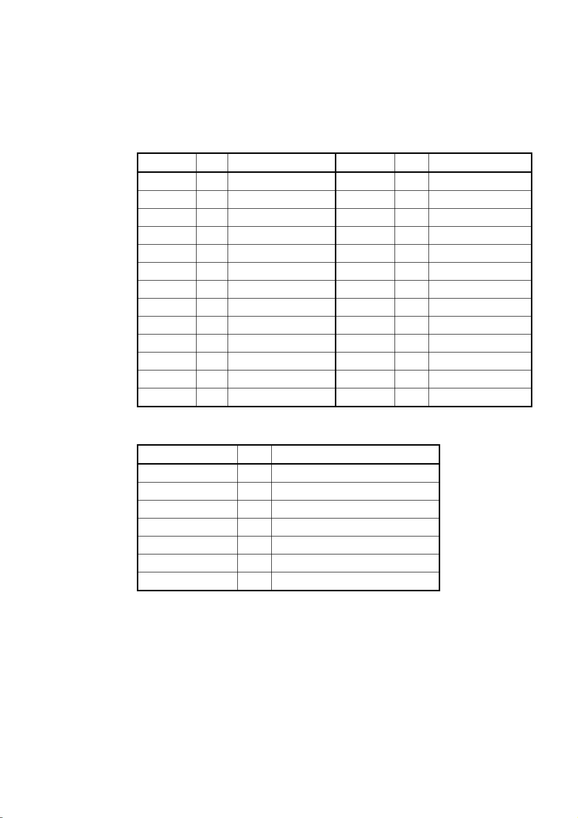
(1) CAMERA LINK connector (Base configuration)
- Connector MDR 26-Pin connector 10226-2210VE (3M)
- Pin assignment
Pin No. I/O Function Pin No. I/O Function
1 - GND 14 - GND
2 Out Tx OUT 0- 15 Out Tx OUT 0+
3 Out Tx OUT 1- 16 Out Tx OUT 1+
4 Out Tx OUT 2- 17 Out Tx OUT 2+
5 Out Tx CLK OUT- 18 Out Tx CLK OUT+
6 Out Tx CLK 3- 19 Out Tx CLK 3+
7 In Ser TC(RxD)+ 20 In Ser TC(RxD)-
8 Out Ser TFG(TxD)- 21 Out Ser TFG(TxD)+
9 In CC1- 22 In CC1+
10 In CC2+ 23 In CC2-
11 In CC3- 24 In CC3+
12 In CC4+ 25 In CC4-
13 - GND 26 - GND
- CAMERA LINK port assignment
Port I/O Function
Port A[7:0] Out ROUT[7:0] (R Image Output)
Port B[7:0] Out GOUT[7:0] (G Image Output)
Port C[7:0] Out BOUT[7:0] (B Image Output)
CC1 In TRG (Trigger Input)
CC2 In Reserved
CC3 In Reserved
CC4 In Reserved
CCD color camera CS6910CL Specification (Rev.A)
The contents described in this document may be changed without prior notice.
6
D4134419A
Page 9

(2) VIDEO OUT/DC IN connector
- Camera-side connector HR10A-10R-12PB (Hirose)
- Cable-side connector HR10A-10P-12S (Hirose)
- Pin assignment
Pin No. I/O Function
1 - GND
2 In +12V IN
3 - GND
4 Out VBS OUT
5 - GND
6 Out HD OUT
7 Out VD OUT
8 - N.C.
9 - N.C.
10 Out WEN OUT
11 In TRG IN
12 - GND
Seen from the back of the main body
3
2
4
1
10
11 12
5
9
8
7
6
CCD color camera CS6910CL Specification (Rev.A)
The contents described in this document may be changed without prior notice.
7
D4134419A
Page 10

7. Dip Switch Settings
You can set communication speed, memory call, and video output mode using the dip switches on the
back of the main camera body.
Dip switch settings are loaded when the power is turned on. Changes will not be reflected if the
switch settings are changed after the power is turned on.
1
2
3
4
5
6
7
8
9
0
O
Communication speed setting
N
Memory call setting
Video output setting
Not used
(1) Communication speed setting
You can set communication speed of the serial communication via CAMERA LINK.
Either 9600 bps, 19200 bps, or 38400 bps can be set.
SW1 SW2 Communication speed
OFF OFF 9600 bps
ON OFF 19200 bps
OFF ON 38400 bps
CCD color camera CS6910CL Specification (Rev.A)
The contents described in this document may be changed without prior notice.
8
D4134419A
Page 11

(2) Memory call setting
You can set setting value save memory numbers, which are called when the power is turned on.
This camera has 8 memory tables in all.
(3) Video output mode setting
You can set the video output mode (analog output/CAMERA LINK output) upon power on.
If this is set to analog output, the camera starts up with the NTSC mode- AE, AWB operation.
The switch setting specifies the initial operation upon power on. After the power is turned on,
you can change the output mode during operation using command control via CAMERA LINK.
SW3 SW4 SW5 Memory number
OFF OFF OFF 0
ON OFF OFF 1
OFF ON OFF 2
ON ON OFF 3
OFF OFF ON 4
ON OFF ON 5
OFF ON ON 6
ON ON ON 7
SW6 Video output mode
OFF CAMERA LINK output
ON Analog output
CCD color camera CS6910CL Specification (Rev.A)
The contents described in this document may be changed without prior notice.
9
D4134419A
Page 12

8. CAMERA LINK Serial Control
(1) Control Functions Overview
The following functions are available to control via CAMERA LINK serial communication
interface (RS232C standard compatible).
- Output Method Selection Analog (NTSC) / Digital (CAMERA LINK)
- Output Image Format Selection SXGA 30fps / SXGA 15fps / VGA 30fps
* The setting is valid only under digital output
mode.
- Shutter Mode Selection Manual / Auto
- Auto Exposure Setting Photometry Range Setting
AE Lock Setting
Exposure Correction Level Setting
- Random Trigger Shutter Operation Setting Random Trigger: Valid / Invalid (Normal Shutter)
Trigger Polarity: Positive / Negative
- Shutter Speed Setting
- Analog Pre-gain Setting
- White Balance Operation Setting FULL AUTO / One-push AUTO / MANUAL
Manual Color Temperature Setting
R,B Gain Setting
- Gamma Characteristics Selection 0.45 / 0.65 / 1.0 / User Settings
- Edge Enhancement Setting Edge Enhancement Level Setting
- Color Matrix Setting
- Setting Value Memory SAVE / LOAD /RESET
- Readout of Each Camera Data
CCD color camera CS6910CL Specification (Rev.A)
The contents described in this document may be changed without prior notice.
10
D4134419A
Page 13

(2) Command Communication Protocol
The command communication protocol is the teli standard method (method in which parameters
are set in the registers in the camera).
In command send/receive operation, hexadecimal address and data are converted to ASCII data.
All ASCII alphabetic characters used are uppercase characters.
Write to a register
To write data in a register, send a command, as follows:
STX(0x02) Addr. (upper) Addr. (lower) Data (upper) Data (lower) ETX(0x03)
For example, to write data 0x25 to address 0x75, send a command, as follows:
STX(0x02) “7”(0x37) “5”(0x35) “2”(0x32) “5”(0x35) ETX(0x03)
The camera responds to the write command with No Error (ACK) or Error (NAK), as follows:
STX(0x02) ACK(0x06) ETX(0x03)
STX(0x02) NAK(0x15) ETX(0x03)
Reading the register
To read data from a register, send "R" and "Q" following the address.
For example, to read data in address 0x6D, send a command, as follows:
STX(0x02) “6”(0x36) “D”(0x44) “R”(0x52) “Q”(0x51) ETX(0x03)
The camera responds to the read request, as follows:
STX(0x02) Data (upper) Data (lower) ETX(0x03)
CCD color camera CS6910CL Specification (Rev.A)
The contents described in this document may be changed without prior notice.
11
D4134419A
Page 14

(3) Register Map
The registers accessible to the user are as follows:
Address Function bit7 bit6 bit5 bit4 bit3 bit2 bit1 bit0
Base Registers 0x00
Self Check
Registers
0x41
Memory
Registers
0x51 Memory Save Save Bank No. 0x52 Memory Load Load Bank No. 0x53 Memory Reset Reset Bank No. 0x54
Base Function
Registers
Vendor Name
|
(Read Only)
0x03
0x04
Reserved rsv. 0x00
|
0x0F
0x10
Model Name
|
(Read Only)
0x1F
0x20
Serial Number
|
(Read Only)
0x2F
0x30
CPU Version
|
(Read Only)
0x3F
Self-Check
0x40
(Read Only)
Status
(Read Only)
0x42
|
Reserved rsv. 0x00
0x4F
Memory Information
0x50
(Read Only)
|
Reserved rsv. 0x00
0x5F
Update Registers
0x60
Value (Write Only)
Resolution Information
0x61
(Read Only)
Frame Rate
0x62
Information
(Read Only)
0x63
Resolution
0x64
Frame Rate
Shutter Type
0x65
(Read Only)
Shutter Mode rsv.
0x66
Trigger Polarity rsv.
0x67
Number Of Memory Banks In This Camera 0x08
Maximum Resolution That This Camera Supports 0x07
Maximum Frame Rate at Maximum Resolution 0x04
Vendor Name
”TELI”
Model Name
”CS6910CL”
Serial Number -
CPU Firmware Version
ex)”V010000”
Self-Check Result -
Status Code -
rsv. 1:EXEC -
0x04:VGA
0x07:SXGA
0x80:NTSC
0x03:15fps
0x04:30fps
0x06:60fps
rsv. 0:Global 0x00
0:
Normal
1:RTS
0:NEG
1:POS
Default
Value
<<
<<
<<
0x07
0x04
0x00
0x00
CCD color camera CS6910CL Specification (Rev.A)
The contents described in this document may be changed without prior notice.
12
D4134419A
Page 15

Address Function bit7 bit6 bit5 bit4 bit3 bit2 bit1 bit0
Base Function
Registers
0x6C Exposure Adjust
0x6D
0x6E
0x6F
0x70 Gain (Lower) 0x00
0x71 Gain (Upper)
0x72 Setup (Lower) rsv. 0x00
0x73 Setup (Upper) rsv. 0x00
0x74 WB Mode rsv.
0x75
0x76 WB Auto Mode rsv. 0x00
0x77
0x78
0x79
0x7A
0x7B
0x7C Aperture rsv.
0x7D Gamma rsv.
Random Trigger
0x68
Shutter Mode
0x69
Exposure Mode rsv.
AE Area rsv.
0x6A
AE Lock rsv.
0x6B
Denominator Of
Exposure Time
(Lower)
Denominator Of
Exposure Time
(Upper)
Numerator Of
Exposure Time
Manual Color
Temperature
One-Push WB
(Write Only)
Manual R Gain
(Lower)
Manual R Gain
(Upper)
Manual B Gain
(Lower)
Manual B Gain
(Upper)
0x7E
|
Reserved rsv. 0x00
0xAF
Denominator Of Exposure Time
rsv.
0xFF:Manual R and B Gain Available
rsv.
Exposure Adjust Value
(0-9)
(0x0001-0x3A98)
Numerator Of Exposure Time
(0x01-0x08)
Analog Pre-Gain
(0x0000-0x00BF)
0x1E:3000[K]
0x25:3700[K]
0x28:4000[K]
0x2D:4500[K]
0x37:5500[K]
0x41:6500[K]
rsv. 1:EXEC -
R Gain
(0x0000-0x005F)
B Gain
(0x0000-0x005F)
Aperture
(0-7)
0: γ=0.45
1: γ=0.65
2: γ=1.0
3:User Preset0
0:Fix
1:Pulse
0:
Normal
1:Auto
0:
Center
1:Spot
0:OFF
1:ON
0:MWB
1:AWB
2:OPWB
Default
Value
0x00
0x00
0x00
0x00
0x06
0x1E
0x00
0x01
0x00
0x00
0x37
0x39
0x00
0x2A
0x00
0x04
0x01
CCD color camera CS6910CL Specification (Rev.A)
The contents described in this document may be changed without prior notice.
13
D4134419A
Page 16

Address Function bit7 bit6 bit5 bit4 bit3 bit2 bit1 bit0
Expansion
Registers
0xB1
0xB2
0xB3
0xB4
0xB5 Data Register Indirect Access Data Register -
0xB6
0xB7 Sum Register Indirect Access Sum Register -
0xB8
0xC0 CRB Coefficient Color Matrix CRB Coefficient 0x4B
0xC1 CRR Coefficient Color Matrix CRR Coefficient 0x64
0xC2 CBR Coefficient Color Matrix CBR Coefficient 0x41
0xC3 CBB Coefficient Color Matrix CBB Coefficient 0x5A
Target Address
0xB0
0-7 Register
Target Address
8-15 Register
Target Address
16-23 Register
Target Address
24-31 Register
Target Address
32-39 Register
Data Length
Register
Expansion Status
(Read Only)
0xB9
Reserved rsv. 0x00
|
0xBF
0xC4
Reserved rsv. 0x00
|
0xCF
Indirect Access Target Address Register (bit0-7) 0x00
Indirect Access Target Address Register (bit8-15) 0x00
Indirect Access Target Address Register (bit16-23) 0x00
Indirect Access Target Address Register (bit24-31) 0x00
rsv. 0x00
rsv. Indirect Access Data Length 0x00
Expansion Status Code -
Default
Value
CCD color camera CS6910CL Specification (Rev.A)
The contents described in this document may be changed without prior notice.
14
D4134419A
Page 17

(4) Access to Indirect Registers
To set the user-specified gamma table, use indirect access registers.
For indirect access, seven bytes of direct registers are used. These direct registers are as follows:
Target Address 0-7 Register (Direct address: 0xB0)
Target Address 8-15 Register (Direct address: 0xB1)
Target Address 16-23 Register (Direct address: 0xB2)
Target Address 24-31 Register (Direct address: 0xB3)
Target Address 32-39 Register (Direct address: 0xB4
Data Register (Direct address: 0xB5)
Data Length Register (Direct address: 0xB6)
Sum Register (Direct address: 0xB7)
The function of each register is as follows.
* This register is not used in this camera.)
Target Address *-* Register
Indicates the address whose data is referred to or to which data is written.
Data Register
During read operation, data stored in the Target Address *-* register is read.
During write operation, the specified data is written to the Target Address *-* Register.
When read or write operation is completed, the Target Address *-* Register is
incremented.
Data Length Register
Set the number of bytes to be read continuously. (Specified value +1) bytes of data are
read continuously.
If 0 is specified, one byte of data is read.
Sum Register
Every time a write or read command is executed for the Data Register, one-byte
hexadecimal data read or written is added to the value of this register and the result is
stored in this register.
When continuous write or continuous read is performed after 0x00 is written into this
register, the camera side Check Sum of the data read or written data is stored after the
continuous write or continuous read.
CCD color camera CS6910CL Specification (Rev.A)
The contents described in this document may be changed without prior notice.
15
D4134419A
Page 18

With the indirect access registers (Data Register: address 0xB5), continuous data write and
continuous data read can be performed.
Up to 32 bytes of data can be written or read by continuous write or read.
Continuous write
To perform continuous write, send a command as follows.
In continuous write, data of any length (up to 32 bytes) can be written.
The data length for continuous write has no relation to the setting value in the Data Length
Register (address 0xB6).
The camera treats a reception of ETX, as the end of data.
STX(0x02) “B”(0x42) “5”(0x35)
Data0(Upper) Darta1(Upper)Data0(Lower) Data1(Lower)
Data31(Upper) Data31(Lower)
Continuous read
In continuous read, the camera responds as follows.
If you request a read operation for the Data Register (address 0xB5), (the setting value of the
Data Length Register (address 0xB6) + 1 byte) of data is read continuously.
STX(0x02)
Data0(Upper) Data0(Lower) Data1(Upper) Data1(Lower)
ETX(0x03)
ETX(0x03)Data31(Upper) Data31(Lower)
Register map in the indirect address space
The register map in the direct address space is as follows.
Address Function bit7 bit6 bit5 bit4 bit3 bit2 bit1 bit0
0x8000000000
|
User Gamma 0 User Gamma 0 -
0x80000003FF
Default
Value
CCD color camera CS6910CL Specification (Rev.A)
The contents described in this document may be changed without prior notice.
16
D4134419A
Page 19

V-timing
(Exposing)
FVAL
LVAL
9. Timing Charts
(1) SXGA output timing
The contents described in this document may be changed without prior notice.
DVAL
(PIXEL DATA)
51H 960H 36H 3H
1050H
17
CCD color camera CS6910CL Specification (Rev.A)
H-timing
(PIXEL DATA)
PXCK:49.0909MHz(30fps mode)/24.5454MHz(15fps mode)
PXCK
FVAL
LVAL
DVAL
1 2 3
1280clk279clk 1clk
1560clk = 1H
1278127912
1278127912
80
12
77
80
D4134419A
1560clk x 56
1560clk x 361560clk x 960
Page 20

V-timing
(Exposing)
FVAL
LVAL
(2) VGA output timing
The contents described in this document may be changed without prior notice.
DVAL
(PIXEL DATA)
34H 480H 11H
525H
18
CCD color camera CS6910CL Specification (Rev.A)
H-timing
(PIXEL DATA)
PXCK
FVAL
LVAL
DVAL
PXCK:24.5454MHz
1 2 3
63863964
0
640clk139clk 1clk
1560clk = 1H
780clk
63
7
63863964
0
D4134419A
1560clk x 34
1560clk x 480
Page 21

10. Outline Drawing
CCD color camera CS6910CL Specification (Rev.A)
The contents described in this document may be changed without prior notice.
19
D4134419A
Page 22

11. Cases for Indemnity (Limited Warranty)
We shall be exempted from taking responsibility and held harmless for damage or losses incurred by
the user in the following cases
• In case damage or losses are caused by fire, earthquake, or other acts of God, acts by a third party,
deliberate or accidental misuse by the user, or use under extreme operating conditions.
• In case indirect, additional, consequential damages (loss of business interests, suspension of business
activities) are incurred as result of malfunction or non-function of the equipment, we shall be
exempted from responsibility for such damages.
• In case damage or losses are caused by failure to observe the information contained in the
instructions in this instruction manual and specifications.
• In case damage or losses are caused by use contrary to the instructions in this instruction manual and
specifications.
• In case damage or losses are caused by malfunction or other problems resulting from use of
equipment or software that is not specified.
• In case damage or losses are caused by repair or modification conducted by the customer or any
unauthorized third party (such as an unauthorized service representative).
• Expenses we bear on this product shall be limited to the individual price of the product.
CCD color camera CS6910CL Specification (Rev.A)
The contents described in this document may be changed without prior notice.
20
D4134419A
Page 23

12. Restriction for Use
• Should the equipment be used in the following conditions or environments, give consideration to
safety measures and inform us of such usage:
1. Use of the equipment in the conditions or environment contrary to those specified, or use outdoors.
2. Use of the equipment in applications expected to cause potential hazard to people or property,
which require special safety measures to be adopted.
• This product can be used under diverse operating conditions. Determination of applicability of
equipment or devices concerned shall be determined after analysis or testing as necessary by the
designer of such equipment or devices, or personnel related to the specifications. Such designer or
personnel shall assure the performance and safety of the equipment or devices.
• This product is not designed or manufactured to be used for control of equipment directly concerned
with human life (*1) or equipment relating to maintenance of public services/functions involving
factors of safety (*2). Therefore, the product shall not be used for such applications.
(*1): Equipment directly concerned with human life refers to.
· Medical equipment such as life-support systems, equipment for operating theaters.
· Exhaust control equipment for exhaust gases such as toxic fumes or smoke.
· Equipment mandatory to be installed by various laws and regulations such as the Fire Act or
Building Standard Law.
· Equipment related to the above.
(*2) :Equipment relating to maintenance of public services/functions involving factors of safety
refers to.
· Traffic control systems for air transportation, railways, roads, or marine transportation
· Equipment for nuclear power generation.
· Equipment related to the above.
CCD color camera CS6910CL Specification (Rev.A)
The contents described in this document may be changed without prior notice.
21
D4134419A
Page 24

Head Office:
7-1, 4 chome, Asahigaoka, Hino-shi, Tokyo, 191-0065, Japan
(Overseas Sales Department)
Phone: +81-42-589-8771 Fax: +81-42-589-8774
URL: http://www.toshiba-teli.co.jp
Distributor
This product must be classified for disposal according to the laws of each country and municipal laws.
•
Information contained in this document is subject to change without prior notice.
•
CCD color camera CS6910CL Specification (Rev.A)
The contents described in this document may be changed without prior notice.
22
D4134419A
 Loading...