

Page 1

B/W CCD Camera
CS3950D
Specification
Contents
1. Product Description ·································································································1
2. Features ·························································································································1
3. Configuration················································································································2
4. Option Unit····················································································································2
5. Operation Mode ···········································································································2
6. Specifications ················································································································7
7. Timing Chart ················································································································14
8. External View Drawing·······························································································16
D4133738B
0
Page 2
CAUTION
!
!!
!
BEFORE USE - GENERAL SAFETY INSTRUCTIONS
This instruction manual contains important information for the operator (user) and/or people around
him/her to avoid personal injuries, or property damages against him/her or people around him/her by
using this product correctly.
• Prior to use, read this operation manual carefully to fully understand its instructions for correct
use.
• After reading, keep this manual by the side of your equipment for your future reference.
WARNINGS & CAUTIONS
[Definition of markings]
The meaning of each mark used in this instruction manual is given below.
!
!
!!
DANGER
Notes
*1 : Personal injuries mean wounds, burns, electric shocks, and others for which the person injured
need not to be hospitalized nor to be cared for the long term.
*2 : Material damages mean any direct or consequential damages related to property or material loss.
This mark indicates what the user SHOULD NOT DO. The details of things which the
user should not do are described next to this mark.
This mark indicates what the user MUST DO. The details of things which the user
must do are described next to this mark.
This mark indicates that the user must be alert against a possible DANGER. The
details of the danger which the user must be aware of are described next to this mark.
This mark indicates that the user are given a CAUTION against possible hazards. The
details of the caution which the user must be aware of are described next to this mark.
This mark warns the user that improper use, indicated with this mark,
may cause death or severe personal injuries against the user or people
around him/her.
This mark warns the user that improper use, indicated with this mark,
may cause personal injuries (*1) or material damages (*2) against the
user or people around him/her.
i
D4133738B
Page 3
●Handling Precautions
If any overheating sign is observed, discontinue the use immediately.
In the event that smoke, smell, or any other overheating sign is observed, turn its
power switch OFF immediately, and remove your plug from outlet. Do NOT try to
continue to use this device. To do so in spite of clear signs of malfunction invites a
Unplug
fire, an electric shock hazard, or a serious damage. In such case, contact us or our
dealer /distributor from which you purchased this device for repair service.
If any malfunctioning sign is observed, discontinue the use immediately.
Do NOT try to use this device when it is obviously malfunctioning. (Example: No
images on the monitor) In the event of malfunction, turn its power switch OFF
Unplug
immediately, and remove the plug from the outlet. In such case, contact us or our
dealer/distributor from which you purchased this device for repair service.
If any liquid gets into the device, discontinue the use immediately.
In the event that water, or any other type of liquid gets into the body, do NOT try to
continue to use the device. To do so invites a fire or an electric shock hazard. In that
case, turn its power switch OFF immediately, and then remove the plug from the
Unplug
outlet. After that, contact us or our dealer/distributor from which you purchased this
device for repair service/technical advice.
DANGER
Unplug
Unplug
NEVER pull
apart
Avoid
If any foreign object gets into the body, discontinue the use immediately.
In the event that grits, small particles, or any other foreign objects get inside, do NOT
try to continue to use the device. To do so invites a fire or an electric shock hazard. In
that case, turn its power switch OFF immediately, and then remove the plug from the
outlet. After that, contact us or our dealer/distributor from which you purchased this
device for repair service/technical advice.
If any outer strong impact is given to this device, discontinue the use immediately.
In the event that this device is dropped onto the ground, or its cabinet is damaged,
turn its power switch OFF immediately, and remove the plug from the outlet. Do
NOT try to continue to use the device. To do so invites a fire or an electric shock
hazard. In such case, contact us or our dealer/distributor from which you purchased
this device for repair service.
Do NOT disassemble this device.
Do NOT attempt to pull apart, repair, or modify the device on your own. To do so
might lead to a fire or an electric shock accident. Contact us or the dealer/distributor
from which you purchased the device for repair/modification.
Do NOT supply any power other than specified.
This device is designed to work only under specified voltage. Do NOT attempt to
supply the device with power other than specified. Supplying the device with
unspecified power invites a fire or an electric shock hazard.
Do NOT place the device unstably.
Do NOT place the device on an unstable table, sloped ground, etc.. Make sure that the
Avoid
device do not fall nor roll over to prevent an accident.
Do NOT remove the protective cover
Avoid removing its protective cover. If you touch the inner high-voltage part, you might
get an electric shock. For inner part/circuit checkup, maintenance, or repair, contact us
Avoid
or the dealer/distributor from which you purchased this device.
ii
D4133738B
Page 4
process, nor bend forcefully the power cord. Pulling
DANGER
Do NOT place any potentially-hazardous things on this device.
Do NOT place any things on the device which may, if it gets into the inside of the
body, damage the inner parts of the device (such as a flower pot, glass, cosmetics, a
container filled with liquids or chemicals, as well as small metal parts, etc.). If
Avoid
tumbled, the liquids inside the bottle, etc. may get into the chassis, causing a fire or an
electric shock accident.
Do NOT damage the power cord.
Do NOT damage, break, reforcefully/Twisting/Placing a heavy object on/Applying heat on the cord should also
be avoided. Otherwise, the cord may be damaged, causing a fire or an electric shock
Avoid
accident. If the cord is damaged, contact us or our dealer/distributor from which you
purchased this device for repair service.
Unplug
Avoid
Avoid
Avoid
Avoid
CAUTION
Unplug the power-plug when the your device is not in use.
For safety, make sure to unplug the power-plug before you give your device a
cleanup, or when it is not used. Keeping the power-cord connected might invite a fire
or an electric shock hazard.
Do NOT expose your device to direct sunlight, nor intensive heat.
Do NOT place this device where it is exposed to direct sunlight, or in a high
temperature condition. To do so may cause the inner temperature of the device to go
up, resulting in burning-down of inner parts, circuits or a fire accident.
Do NOT connect/disconnect connectors before turning power off.
Make sure to check the camera power is OFF before connecting/disconnecting
connectors. Otherwise, you might get an electric shock, or your camera might break
down.
Do NOT attempt to make connection before turning power off
Make sure to check the camera power is OFF before connection. Otherwise, you
might get an electric shock.
Do NOT pull the cord itself
When disconnecting the power-plug out of the outlet, make sure to hold the plug,
and then pull it out. Do NEVER try to pull the cord itself. Otherwise, the cord may
be damaged or broken, leading to a fire or an electric shock accident.
Do NOT place your device too close to a heater.
Do NOT place your device or its power cord too close to any heating appliance.
Avoid
Otherwise, the coating of its switch and/or power-cord may melt, leading to a fire or
an electric shock accident.
Do NOT use chemical solvent for cleanup.
When giving your camera a cleanup, avoid using a benzene, alcohol, and thinner.
Avoid
These chemicals might cause its coating or markings to come off or become
degraded.
Do NOT handle the power cord with your hand in an wet condition.
Do NOT plug in/out the power cord with an wet hand. Otherwise, it may cause an
Avoid
electric shock accident.
iii
D4133738B
Page 5

This device complies with Part15 of the FCC rules. Operation is subject to the following two
conditions: (1) This device may not cause harmful interference, and (2) This device must accept any
interference received, including interference that may cause undesired operation.
RESTRICTION FOR USE
Avoid irregular signal interface.
Do not attempt irregular signal interface other than specified. Under signal interface other than
recommended/specified in this instruction manual, the device might fail to exert the maximum
performance. In much worse case, if you continue to use your device under incorrect signal
interface, part(s) of inner circuits might burn down.
DISCRAMER (RIMITED WARRANTY)
We disclaim any responsibility and shall be held harmless for damages or losses incurred by user(s)
in either of the following cases.
1.In case damages or losses are caused by fire, earthquake, or other acts of Gods, the act by third
party, misuse by the user deliberately or erroneously, use under extreme operating conditions.
2.In case any indirect, additional, consequential damages (loss of expected interest, suspension of
business activities) are incurred as results of malfunction or non-function of this device, we
shall be exempted from assuming responsibility for such damages.
3.In case damages or losses are caused by incorrect use which is not in line with the instructions
given in this instruction manual.
4.In case damages or losses are caused by malfunction resulting from bad connection with other
equipment.
5.In case damages or losses are caused by repair or modification done by the user.
iv
D4133738B
Page 6

OTHER INSTRUCTIONS
Do NOT use power other than specified
Be sure to use DC12V power supply. The camera is designed to work only under the specified voltage.
Do NOT attempt to drive the camera with the power other than DC12V. Operating the camera under
power other than DC12V invites a fire or an electric shock hazard.
Avoid intensive light
Do NOT expose the camera’s image-pickup-plane to sunlight or other intense light directly. If the part
of CCD is exposed to spot-intensive light, you might get a picture problem like blooming and/or smear.
Under the comparison at the same video output level, the faster the electronic shutter speed setting, the
more smear is generated.
Use under right operation condition
This equipment is designed and guaranteed to work under the temperature range of 0 to 40 degrees C
and 30 through 90% humidity range. Avoid using the equipment beyond that limits.
Handle with care
Take care not to drop the equipment, nor give strong impact, as this may cause breakdown.
Do NOT tamper with switches
Read this operation guide thoroughly before you touch switches and adjusters on the rear panel.
Do NEVER attempt to disassemble the camera and/or tamper with any inner switches, potentiometers,
etc.
Avoid liquid
Avoid placing the camera where it is likely to be splashed with water or any other fluids. Operating
the camera with its inner parts/circuits in an wet condition might cause a damage or an electric shock
accident.
Avoid placing near TV/radio
This camera might cause an interference (e.g. noise) if used around radio / TV set. In such a case,
change the location of your camera (or radio / TV).
Abnormal operation
In the event that any abnormal condition is observed, turn the power switch OFF immediately. Do
NOT try to continue to use the camera. To do so reckless of visible signs of malfunction invites a fire,
an electric shock hazard, or any other serious damage to the camera. In such case, contact us or our
dealer/distributor from which you purchased the camera for repair service.
Camera installation
For mounting this camera, use screws having inner depth (the portion which go inside the camera
chassis side) shorter than 3.5mm for M3.0, 4 places or 3.0mm for M2.0, 4 places. Longer screws
contact and might damage inner boards/parts.
Waste treatment
Wastes of this product should be separated and discarded in compliance with the various national and
local ordinances.
v
D4133738B
Page 7

1. PRODUCT DESCRIPTION
Model CS3950D is an integrated type B/W CCD camera with a XGA format all-pixel-data readout
CCD. The model is suited for high-speed, high-resolution image processing use. Its compact,
light-weight body is ideal for system integration.
2. FEATURES
(1) All pixel's data readout
With its built-in all-pixel-data-readout CCD, this model can read out image-data just in
approximately 1/30 sec. A frame-shutter reads out all data even under RTS (Random Trigger
Shutter) mode.
(2) High resolution
XGA (1024 x 768 pixels) 800k CCD
(3) Square grid pattern CCD
Pixel's in CCD are aligned in square grid pattern. This makes it easier to perform computation
correctly for image processing use.
(4) External Sync.
The camera is switched over to external synchronization operation automatically when external
HD signal is input.
(5) Random trigger shutter function
With a built-in RTS, the camera’s CCD starts light-exposure in synchronization with external
trigger signals. This function enables the camera to capture fast-moving subjects at constant
position for precise image processing.
(6) Restart / Reset
Under the restart / reset mode, this model can capture images at an arbitrary timing cued by
external VD signal.
(7) Partial-scan
Under the partial scan mode, only 1/2 or 1/4 screen center portion of image information is read
out, resulting in a faster operation.
(8) Compact & light-weight camera
The model features its compact and light-weight camera, freeing you from your
integration-space-problem. In addition, it has an excellent shock and vibration resistance.
3. CONFIGURATION
(1) Camera body·····································································1
(2) Accessory
Operation Manual(English)·············································1
D4133738B
1
Page 8

4. OPTION UNIT
(1) DC SYNC IN cable ············Model name : CPRC3700 [2m,3m,5m,10m]
(2) Camera adapter ···················Model name : CA170
(3) Camera-mounting kit············Model name : CPT
*Contact your dealer / distributor for details of option units.
*Conformity of an option part and EMC conditions
About the conformity of EMC standard of this machine, it has guaranteed in the
conditions combined with the above-mentioned option part.
When used combined parts other than specification of our company, I ask you to have
final EMC conformity checked of a visitor with a machine and the whole equipment.
OPERATION MODE
5.
(1) GAIN selection (Camera rear-panel SW)
Switches sensitivity setting
(1-1) FIX -------------------Factory-prefixed gain
(1-2) MANU --------------- Gain is adjustable via the manual gain potentiometer (M.GAIN)
(2) TRIG selection (Camera rear-panel DIP SW)
Switches TRIG input signal polarity used under RTS mode
(2-1) POSI------------------ Positive polarity (rising edge detection)
(2-2) NEGA----------------Negative polarity (falling edge detection)
(3) RTS (Random Trigger Shutter) exposure selection (Camera rear-panel DIP SW)
Switches light exposure mode under RTS mode
(3-1) FIX mode------------ Rear DIP SW
Exposure-time control via rear-panel DIP switch
(3-2) PULSE W mode----TRIG signal pulse width control
Exposure-time control via TRIG signal pulse width
(4) Shutter mode selection (Camera rear-panel DIP SW or TRIG signal IN [Automatic])
Switches shutter mode
(4-1) NOR mode ----------Normal electronic shutter
Exposure control via internal sync signal
High-speed shutter: From 1/100,000s through OFF (12 position)
(4-2) RTS mode -----------Random trigger shutter
Exposure control via ext. trigger or ext. sync input
Timing charts are shown below. (TRIG timing: Positive)
Notes: * RTS selection is automatic with TRIG status
** Neither under FIX nor PULSE W mode, RTS doesn’t
work if Electronic shutter speed SW is set in OFF
position.
2
D4133738B
Page 9

(a)Non-reset mode (Under internal sync / external sync --- Consecutive VD IN)
Exposure starts at the timing of TRIG signal IN. After each exposure is completed, the
camera outputs video at each next VD IN timing.
Automatically returns to normal shutter
if fixed H level (after appro x. 1/6s)
Definite
TRIG IN
(Positive)
INT/EXT VD
CCD Exposure
VIDEO OUT
WEN OUT
(Standard)
TRIG IN not acceptable for
Outputs VD,V-SYNC
during standby
1V after mode chenge
Exposure time
(E-shutter speed or
pulse width)
Outputs video at the next VD
timing after exposure
Random trigger shutterNormal shutter
(b) Non-reset mode (Under external sync --- Single VD IN)
After TRIG IN and exposure, the camera goes into standby until next ext. VD IN.
TRIG IN not acceptable for
TRIG IN
(Positive)
EXT VD
CCD Exposure
VIDEO OUT
WEN OUT
(Standard)
In sync with ext.VD during standby
(No video output)
Normal shutter
1V after mode chenge
Exposure time
(E-shutter speed or
pulse width)
Outputs video at the next VD
timing after exposure
Random trigger shutter Normal shutter
*Don’t provide ext. VD IN during exposure.
** After automatic return, fix ext. VD IN at Hi.
(c)V-reset mode (Under internal sync / external sync --- No VD IN)
Exposure starts at the timing of TRIG signal IN. After each exposure is completed, the
camera outputs video immediately by resetting VD. (HD is not reset)
Normal shutter
Automatically returns to normal shutter
if fixed H level (after appro x. 1/6s)
Definite
3
D4133738B
Page 10

Automatically returns to normal shutter
if fixed H level (after appro x. 1/6s)
Definite
TRIG IN
(Positive)
CCD Exposure
VIDEO OUT
WEN OUT
(Standard)
TRIG IN not acceptable for
1V after mode chenge
Exposure time
(E-shutter speed or
pulse width)
VD,V-SYNC pause during standby
VD,V-SYNC output for 1V only
Random trigger shutterNormal shutter
Normal shutter
Exposure time delay under RTS
When the RTS is active, both in FIX mode and PULSE W mode, there is a time delay of
approximately 1.4 micro s until the start of exposure after the rising edge of TRIG signal
(positive).
Exposure time under pulse width mode
Under RTS pulse mode, the exposure time is determined by the pulse width. More exactly,
the actual time is the pulse width plus approximately 8.0 micro s.
TRIG IN
Pulse width
CCD
Exposure
Exposure delay time = Approximately 1.4 micro s
Exposure time = Pulse width + Approx. 8.0 micro s
(4-3) Restart / Reset
The restart / reset function is available with the ext.VD signal. You can get an arbitrary
slower shutter speed than normal shutter and random trigger shutter.
Here are some notes;
* The shutter speed (exposure time) is determined by ext. VD signal interval.
** This function is enabled when the rear-panel shutter speed DIP SW is OFF.
*** Supply consecutive HD.
EXT VD IN
CCD Exposure
VIDEO OUT
WEN OUT
(Standard)
WEN OUT
[Option]
The exposure time is
determined by VD interval
4
D4133738B
Page 11

(5) Partial-scan mode selection (Camera rear-panel DIP SW)
Switches partial-scan mode
Note: Sometimes phenomenon called as “whiteout” occurs at the top of the screen when
there is strong incident light entering in the wide area of a CCD, however, this is not
a malfunction. If this occurs, reduce the amount of incoming rays.
(5-1)1/2 Partial-scan --- Screen center 1/2 readout
Only the center portion of 344H out of the total effective lines 768H (excluding BLK
time) is read out. Available both under external / internal mode.
212H
344H
212H
High-speed
transfer
Normal-
speed
transfer
High-speed
transfer
Under normal shutter (Electronic shutter OFF)
■
Notes: * Under ext. sync, the ext. VD should be 1V = 387H.
** Under normal shutter, set the rear-panel DIP SW #5, #6 in OFF.
213
556 213 556
344H
<V-reset>
Normal-
speed
transfer
VIDEO OUT
15H
High-
speed
transfer
9H 9H
WEN OUT
(Standard)
28H
V BLK
(Include
High-speed
transfer)
9H
344H
VIDEO output
time
387H 387H
Under other shutter modes
■
VIDEO OUT
WEN OUT
(Standard)
28H
V BLK
(Include
High-speed
transfer)
9H
213
344H
VIDEO output
time
*2
556
15H
High-
speed
transfer
<Non-reset>
(409H)
*1
9H
*1:Arbitrary under ext.sync
*2:See "7.TIMING CHART (4)WEN timing".
5
D4133738B
Page 12

(5-2)1/4 Partial-scan --- Screen center 1/4 readout
Only the center portion of 137H out of the total effective lines 768H (excluding BLK
time) is read out. Available both under external / internal mode.
316H
137H
315H
Under normal shutter (Electronic shutter OFF)
■
Notes: * Under ext. sync, the ext. VD should be 1V = 193H.
** Under normal shutter, set the rear-panel DIP SW #5, #6 in OFF.
VIDEO OUT
35H
V BLK
(Include
High-speed
transfer)
WEN OUT
(Standard)
9H
High-speed
transfer
Normal-
speed
transfer
High-speed
transfer
317 453 317 453
137H
Video output
time
21H
High
-speed
transfer
193H 193H
9H 9H
137H
Normal-
speed
transfer
<V reset>
Under other shutter modes
■
VIDEO OUT
WEN OUT
(Standard)
35H
V BLK
(Include
High-speed
transfer)
9H
317
*1:Arbitrary under ext.sync
137H
Video output
time
453
21H
High
-speed
transfer
<Non-reset>
(603H)
*1
9H
6
D4133738B
Page 13

6. SPECIFICATIONS
[Basic spec]
(1) Image sensor All Pixel’s Data Read-out Interline CCD
Total pixels 1077(H) x 788(V)
Active pixel 1034(H) x 779(V)
Video output pixels 1024(H) x 768(V)
Scanning area 4.81(H) x 3.62(V) mm (=Equivalent to 1/3 type CCD size)
Unit cell size 4.65(H) x 4.65(V) micro m (Square-grid array)
(2) TV system Special format (Non-conforming to EIA)
(3) Scanning lines 796 lines
(4) Interlace Non-interlace mode
(5) Sync system Internal/External automatic switch-over
(6) Video output VS 1.0V(p-p) / 75Ω, DC coupled, 1 line
(7) Resolution 770 TV lines(H)
768 TV lines(V)
(8) S/N Standard: 50dB(p-p)/rms (Initial factory setting)
(9) Illumination Standard 400 lx (F5.6)
Minimum 4 lx (F1.4) (GAIN MAX, Approx. 50% video output)
(10) Gain FIX (Fixed) gain: Factory-shipped preset level
MANU (Manual) gain: Setting through GAIN VR
FIX / MANU switching via rear-panel SW
(11) Gamma Gamma = 1 (Fixed)
(12) White-clip level Approx. 840mV(p-p) (Excluding SYNC)
(13) Power source DC12V +/-10%
Ripple voltage: 50mV(p-p) or less
(14) Power consumption Approx. 2.0W
[Internal sync spec]
(1) Base clock frequency 29.5MHz (1CLK)
(2) H sync frequency 23.23kHz
(3) V sync frequency 29.2Hz (Under non-interlace)
[External sync spec]
(1) Ext. sync input signal HD/VD
(2) Input level From 2 through 4V (p-p)
(3) Input impedance 75-ohm / High impedance 10k-ohm (switching via rear-panel SW)
(Initial factory setting: High)
(4) Interlace Non-interlace
(5) Polarity Negative
(6) Pulse width HD: 3.46 +/- 1 micro s (LOW)
VD: From 125 through 400 micro s (LOW)
(7) Repeating frequency f
(8) Phase difference HD/VD: 0 +/- 5.0 micro s
= 23.23kHz +/- 1%
H
= fH/796
f
V
7
D4133738B
Page 14

5
[Shutter trigger spec]
Exposure-starting-cue signal in random trigger shutter mode
(1) Input level LOW level: From 0 through 0.5V
HIGH level: From 4 through 5V
(2) Input impedance High impedance (10k-ohm)
(3) Capture timing Rising edge detection (Positive) / Falling edge detection (Negative)
(Switching via rear-panel DIP SW)
(Initial factory setting: Rising edge)
(4) Pulse width Minimum 2 micro s
Maximum 1/8s
[Sync signal spec]
(1) Readout signal WEN readout timing pulse
(2) Polarity Negative
(3) Pulse width 1H output
(4) Output circuit
WEN
V
2SC3734
WEN OUT
100 50
2SA1461
[Electronic shutter spec]
(1)Normal shutter Shutter-speed setting via rear-panel SW (Initial: OFF)
12 steps switch-able (= OFF, 1/60s, 1/125s, 1/250s, 1/500s, 1/1000s,
1/2000s, 1/5000s,1/10000,1/20000,1/50000,1/100000)
(2)RTS
(a)Operation mode
No. Reset Exposure Sync
1 Internal
2 Consecutive HD / Consecutive VD IN
3 Consecutive HD / Single VD IN
Non-reset
4 Internal
5 Consecutive HD / Consecutive VD IN
6 Consecutive HD / Single VD IN
7 Internal
8 Consecutive HD IN
V-reset
9 Internal
10 Consecutive HD IN
Rear SW
(FIX mode)
TRIG pulse width
(PULSE width mode)
Rear SW
(FIX mode)
TRIG pulse width
(PULSE width mode)
Notes : * RTS mode automatically switches over through TRIG IN
**RTS disabled under Electronic shutter OFF
(b)Multiple shutter Multiple shutter via ext. trigger signal and ext. VD signal
Notes : * Operation like No.3, 6 above
8
D4133738B
Page 15

1
Non-reset
Enabled
[Option]
Enabled
2
V-reset
Disabled
3
Consecutive HD VD IN
Non-reset
Enabled
[Option]
Enabled
4
Consecutive HD (VD) IN
V-reset
Disabled
5
Non-reset
Enabled
[Option]
Enabled
6
V-reset
Disabled
7
Consecutive HD VD IN
Non-reset
Enabled
[Option]
Enabled
8
Consecutive HD (VD) IN
V-reset
Disabled
1/2 partial scan
1/4 partial scan
796H
796H
(3)Restart / Reset Restart / reset available via ext. VD signal
(Switching via rear panel DIP SW, Initial OFF)
Notes : * The exposure-time (shutter-speed) is determined by ext.
VD interval.
** Enabled when rear-panel DIP SW OFF.
***Provide Consecutive HD.
[Partial scan]
(1)Operation mode
No Scan mode Sync Reset E-shutter Normal E-shutter RTS
1/2 partial
1/4 partial
Internal
Internal
Note: Items shown as [Option] in this document is not included in your purchase as
standard components. Contact our dealer / distributor for details.
(2) Reset mode
As shown in (1) above, non-reset and V-reset is available.
([Option]: Doesn’t come as standard. Contact our dealer / distributor for details)
(a) non-reset (Electronic shutter enabled)
VD doesn’t get reset after video readout. The interval of VD signal is as follows.
VIDEO OUT
Partial A Partial B Partial C
VD Interval
*Note: Under normal shutter mode, when non-reset is selected on partial scan,
electronic shutter is valid.
Please note that the exposure time is shortened than the setting value
when the external VD is input at shorter than the above VD interval.
(b) V-reset (Electronic shutter disabled)
VD does get reset after video readout. Under internal sync, the interval of VD signal is as
follows.
VIDEO OUT
Partial A Partial B Partial C Partial EPartial D
VD interval
1/2 partial scan 1/4 partial scan
387H 193H
Note: Items shown as [Option] in this document is not included in your purchase as standard
components. Contact our dealer / distributor for details.
9
D4133738B
Page 16

[Mechanical spec]
(1) External dimension 44 x 29 x 78(D) mm (Not including protrusion)
Refer to the attached external view drawing
(2) Weight Approximately 130g
(3) Lens mount C mount
(4) GND / insulation Circuit GND - Chassis electrically conducted
*
* Combination of C
Combination of C----mount lens
* *
Combination of CCombination of C
As for the C-mount lens used combining this camera, the projection distance from
bottom of the screw should use 8.3mm or less.
mount lens
mount lensmount lens
C-mount lens
8.3mm or less
Bottom of
the screw
[Ambient condition]
(1)Environment condition
Performance guaranteed Temperature: From 0 through 40 °C
Humidity: From 30 through 90 % (No condensing)
Operation guaranteed Temperature: From -5 through 50 °C
Humidity: From 10 through 90 % (No condensing)
Storage Temperature: From -20 through 60 °C
Humidity: From 10 through 90 % (No condensing)
(2)EMC conditions (Electro-Magnetic Compatibility)
EMI (Electro-Magnetic Interference)
EN61000-6-4 (Examination level EN55011-A) Conformity
EMS (Electro-Magnetic Susceptibility)
EN61000-6-2 Conformity
*Conformity of EMC conditions
About the conformity of the EMC standard of this machines, it has guaranteed in the
conditions combined with the option part of 4th clause.
When used combining parts other than specification of our company, I ask you to have
final EMC conformity checked of a visitor with a machine and the whole equipment.
10
D4133738B
Page 17

①②③④⑤⑥⑦⑧⑨
⑩
⑪
⑫
[Connector pin assignment]
(1) Compatible connector HR10A-10P-12S (Supplied by HIROSE ELEC.)
(2) Pin assignment
Pin
No.
Signal
(Standard)
Connector pin layout
1 DC12V GND
2 DC12V
3 VIDEO GND
4 VIDEO OUT
5 HD GND
6 HD IN
7 VD IN
8 TRIG GND
9 NC
10
11
12
WEN OUT
TRIG IN
VD GND
12 pin male
Picture Rear-panel camera connector
Notes : *Before connecting / disconnecting the connector, make sure the camera power is OFF.
**For board connection, check compatibility.
(Rear-view)
11
D4133738B
Page 18

123
4
5
6
7
8
Positive
Negative
Shutter mode
Partial scan
Shutter-speed
No.1
No.2
No.3
No.4
OFF
OFF
OFF
OFF
OFF
1/60sONOFF
OFF
OFF
1/125s
OFFONOFF
OFF
1/250s
ONONOFF
OFF
1/500s
OFF
OFFONOFF
1/1,000s
ON
OFFONOFF
1/2,000s
OFFONON
OFF
1/5,000s
ONONON
OFF
1/10,000s
OFF
OFF
OFFON1/20,000s
ON
OFF
OFF
ON
1/50,000s
OFFONOFFON1/100,000s
ONONOFF
ON
Not acceptable
OFF
OFFONON
Not acceptable
ON
OFFONON
1/100s(FL)
OFFONON
ON
Pulse width
ONONON
ON
Partial scan
No.7
No.8
OFF
OFF
OFF
1/2 partial
ON
OFF
1/4 partial
OFF
ON
Not acceptable
ON
ON
V reset
OFF
OFF
Not acceptable
ON
OFF
Non-reset
OFFONON
ON
Non-reset
(Multiple shutter)
Non-reset
ON
OFF
Consecutive VD
V reset
OFFONNo VD
Restart / Reset
SYNC
Shutter mode
[Switch setting]
(1) CCU rear-panel DIP SW
No. Function OFF ON
E-shutter-speed
(SHUT)
(SMODE)
(PART)
9 TRIG polarity
Notes: *Initial factory setting: All OFF
**Set No.9 OFF when TRIG IN OPEN.
(Table 1) Electronic shutter-speed (Table 2) Partial-scan
Notes :
(Table 3) Shutter-mode
Notes :
*Don’t set Electronic shutter-speed in OFF under RTS mode.
Random
trigger
Not acceptable
Random
trigger
* Under normal shutter mode partial-scan, set No.5, 6 in OFF.
**Under PULSE W mode, SYNC reset is disabled.
See shutter-speed table (Table 1)
See shutter-mode table (Table 3)
See partial-scan table (Table 2)
(Rising edge)
No.5 No.6
OFF OFF Single VD
ON ON Single VD
(Falling edge)
Internal sync
Ext. sync
HD IN
SHUT
SHUT
SHUTSHUT
SMODE
SMODE
SMODESMODE
PART
PART
PARTPART
TRIG
TRIG
TRIGTRIG
1
2
O
N
3
4
5
6
7
8
9
0
(2)CCU rear-panel SW
Function SW Selected Function
HIGH HIGH impedance (Initial factory setting) Ext. SYNC IN impedance
(HD/VD)
GAIN selection (GAIN)
75Ω 75Ω
F Factory-set GAIN
M Manual GAIN adjustable via GAIN potentiometer
12
D4133738B
Page 19
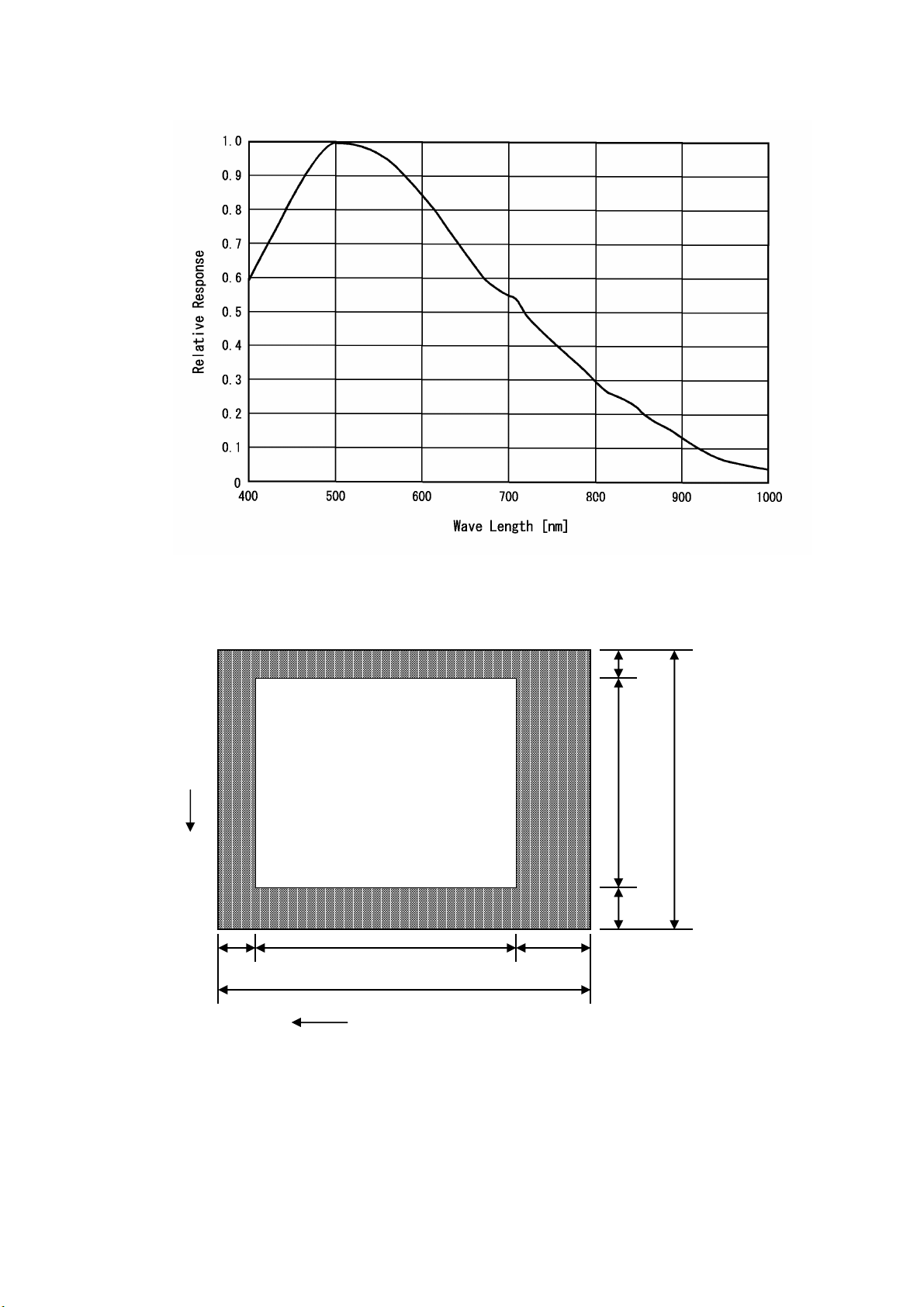
[Relative Spectrum Response]
*Including lens characteristics, Excluding light source characteristics
[Optical black characteristics]
V
3
Effective
Image Area
1034
40
2
779
7
788
1077
H
Total pixels : 1077(H) x 788(V)
Effective pixels : 1034(H) x 779(V)
Optical black
Horizontal : 3pixels --- 40pixels
Vertical : 7pixels --- 2pixels
13
D4133738B
Page 20

(1)H rate timing
7. TIMING CHART7. TIMING CHART
7. TIMING CHART
7. TIMING CHART
EXT HD
±0.5µµµµssss
±±±
1CLK=33.9ns
INT HD
102CLK
(3.46µµµµssss)
5CLK 40CLK 164CLK 29CLK 3CLK
1
1
0
2
9
14
CAM
VIDEO
1
0
0
3
3
0
4
O
B
1
Opt.Blk.
O
B
4
0
H. trans.
pause
H. blanking
246CLK(8.34µµµµssss)
D
1
Dummy
pixels
D
2
9
Opt.
Blk.
5CLK
1 5 6
O
O
O
B
B
B
2
1
3
Effective pixels = 1034CLK
1024CLK 5CLK
V-OUT Effective pixels
1
1
0
2
9
1
0
0
3
3
0
4
OUT
H.SYNC
22CLK
(0.75µµµµssss)
D4133738B
73CLK
(2.47µµµµssss)
151CLK
(5.12µµµµssss)
Horizontal scan (1H)
1270CLK(43.05µµµµssss)
1024CLK
(34.71 µµµµssss)
WEN
OUT
Page 21

(2) V
rate timing
EXT VD IN
INT VD
INT HD
VIDEO OUT
WEN OUT
(Standard)
794
777
1H delay
795
777
778
9H(387μs)
123456789
796
Dummy 7H OB
OB OB
779
1V=796H
101112131415161718
OB
OB OB OB OB OB OB
1H
Ext. VD – Ext. HD phase difference
19202122232425262728293031
1 2 3
4 5 6 7 8 9 10
28H(1205μs)
V.Blanking
333435
32
11 12 13 14 15 16 17
768
EXT VD IN
EXT HD IN
INT VD
TP2
TP1
TP1 : 10.0 us
TP2 : 5.0 us
15
D4133738B
Page 22

8. EXTERNAL-VIEW DRAWING
16
D4133738B
Page 23

Head Office:
(Overseas Sales Department)
Phone: +81-42-589-8771 Fax: +81-42-589-8774
URL:
http://www.toshiba-teli.co.jp
The design and specification is subject to change without notice.
7-1, 4 chome, Asahigaoka, Hino-shi, Tokyo, 191-0065, Japan
17
D4133738B
 Loading...