

Toshiba Compliant Manager BMS-CM1280TLE, Compliant Manager BMS-CM1280FTLE Installation Manual
Page 1
COMPLIANT MANAGER
Model name:
BMS-CM1280TLE
BMS-CM1280FTLE
Installation Manual
• Save These Instructions!
ENGLISH
Page 2

–2–
Compliant Manager
Installation Manual
Contents
1 PRECAUTIONS FOR SAFETY . . . . . . . . . . . . . . . . . . . . . . . . . . . . . . . . . . . . . . . . . . . 3
2 PACKAGED ITEMS OF COMPLIANT MANAGER . . . . . . . . . . . . . . . . . . . . . . . . . . . . 4
3 INSTALLATION OF THE COMPLIANT MANAGER . . . . . . . . . . . . . . . . . . . . . . . . . . . 5
4 CONNECTION OF POWER CABLES/SIGNAL WIRES/EARTH WIRES . . . . . . . . . . . 6
5 MODE SETTING FOR THE CONTROLLER . . . . . . . . . . . . . . . . . . . . . . . . . . . . . . . . . 8
6 SWITCHES FOR SETTING . . . . . . . . . . . . . . . . . . . . . . . . . . . . . . . . . . . . . . . . . . . . . 10
7 CENTRAL CONTROL ADDRESS (GROUP NUMBER) SETTING . . . . . . . . . . . . . . . 14
8 ZONE SETTING . . . . . . . . . . . . . . . . . . . . . . . . . . . . . . . . . . . . . . . . . . . . . . . . . . . . . . 17
9 CHANGING RETURN-BACK TIME/TEMPERATURE SETTINGS . . . . . . . . . . . . . . . 18
10 TEST RUN . . . . . . . . . . . . . . . . . . . . . . . . . . . . . . . . . . . . . . . . . . . . . . . . . . . . . . . . . . 21
11 SPECIFICATIONS . . . . . . . . . . . . . . . . . . . . . . . . . . . . . . . . . . . . . . . . . . . . . . . . . . . . 21
1-EN
Page 3
–3–
Compliant Manager
Installation Manual
1 PRECAUTIONS FOR SAFETY
After the installation work, perform a trial operation to check for any problem. Explain how to use and maintain the
unit to the customer. Ask the customer to keep this Installation Manual.
WARNING
• Ask an authorized dealer or qualified installation professional to install or reinstall the Compliant
Manager.
Improper installation may result in electric shock or fire.
• Turn off the main power supply switch or breaker before attempting any electrical work.
Make sure all power switches are off. Failure to do so may cause electric shock.
• Perform installation work properly according to this Installation Manual.
Improper installation may result in electric shock or fire.
• Do not modify the unit.
Any modification may cause a malfunction, resulting in overheating or fire.
CAUTION
• Do not install the unit at a place subject to leakage of flammable gas.
If flammable gas leaks and remains around the unit, it may catch fire.
• Perform wiring correctly in accordance with the specified current capacity.
Failure to do so may result in short-circuiting, overheating, or fire.
• Connect the specified cables for the terminals securely to prevent external forces from affecting
them.
Failure to do so may result in disconnection, overheating, or fire.
• Make sure that the ground connection has been properly made.
Improper grounding may result in electric shock. Ask your dealer or an installation professional about how to check
the ground connection.
• Do not install the unit at a humid place or a place subject to vibration.
High humidity or vibration may cause a failure of the unit.
• Do not expose the unit to direct sunlight or a heat source.
This may cause a failure of the unit.
• Do not install the unit at a place where noise is generated.
This may cause a malfunction of the unit.
REQUIREMENT
• Disconnect the appliance from the main power supply.
This appliance must be connected to the main power supply by a circuit breaker or switch with a contact
separation of at least 3mm.
2-EN
Page 4
–4–
Compliant Manager
Installation Manual
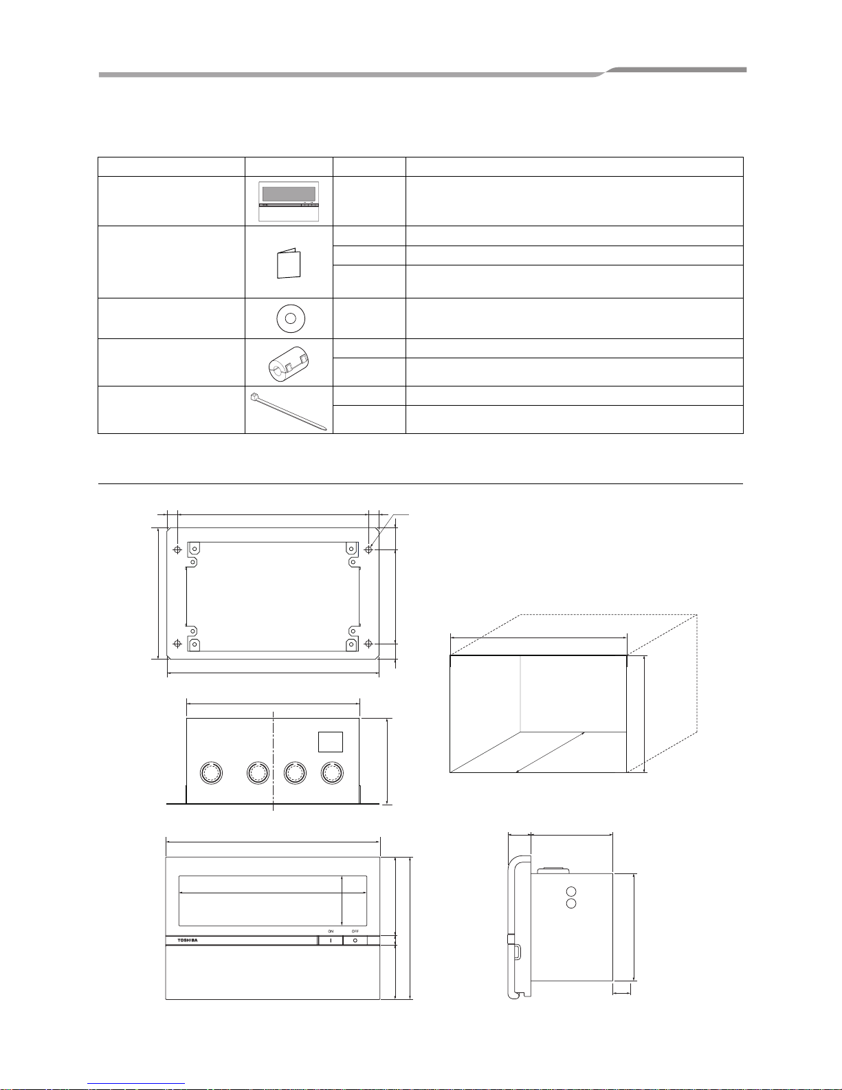
2
PACKAGED ITEMS OF COMPLIANT MANAGER
External Dimensions
Part name Image Quantity Remarks
Compliant Manager 1
Manual
1 Owner’s Manual
1 Installation Manual
1
Network Setting Manual
* Packaged for BMS-CM1280FTLE only
CD-R 1 * Packaged for BMS-CM1280FTLE only
Clamp filter
2 BMS-CM1280TLE
4 BMS-CM1280FTLE
Tie-wraps
2 BMS-CM1280TLE
4 BMS-CM1280FTLE
180
8.5
5Ø
8.5 155
142
172
19 69
90
158
42
46 66
120
8
17.9
76
12.7
106.6
70
140
108
90
*
* Reserve space of 10mm or more
when installin
g
the unit.
Dimensions of unit fixing holes in the wall, etc.
3-EN
Page 5
–5–
Compliant Manager
Installation Manual
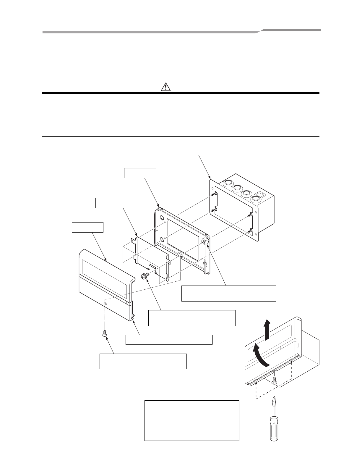
3 INSTALLATION OF THE COMPLIANT
MANAGER
CAUTION
• Do not twist communication wires (used between indoor unit and outdoor unit and used for central control) and input/
output wires with power wires or bundle them together with power wires in a metal tube. Doing so may cause
malfunction.
• Install the Compliant Manager away from a noise source.
• When noise is induced into the power supply of the Compliant Manager, take proper measures such as attaching of
a noise filter.
Panel
Shield plate
Base
Power supply box
The panel is secured with the claw.
This screw secures the power
supply box, base, and shield plate.
The panel is secured with the screw
at the bottom.
This hole is provided for penetration of
the power supply box fixing screw.
Remove the screw at the bottom of the
panel, insert a flat-blade screwdriver or
the like into the right and left grooves at
the bottom of the panel, and then
carefully detach the panel with the
screwdriver.
4-EN
Page 6
–6–
Compliant Manager
Installation Manual
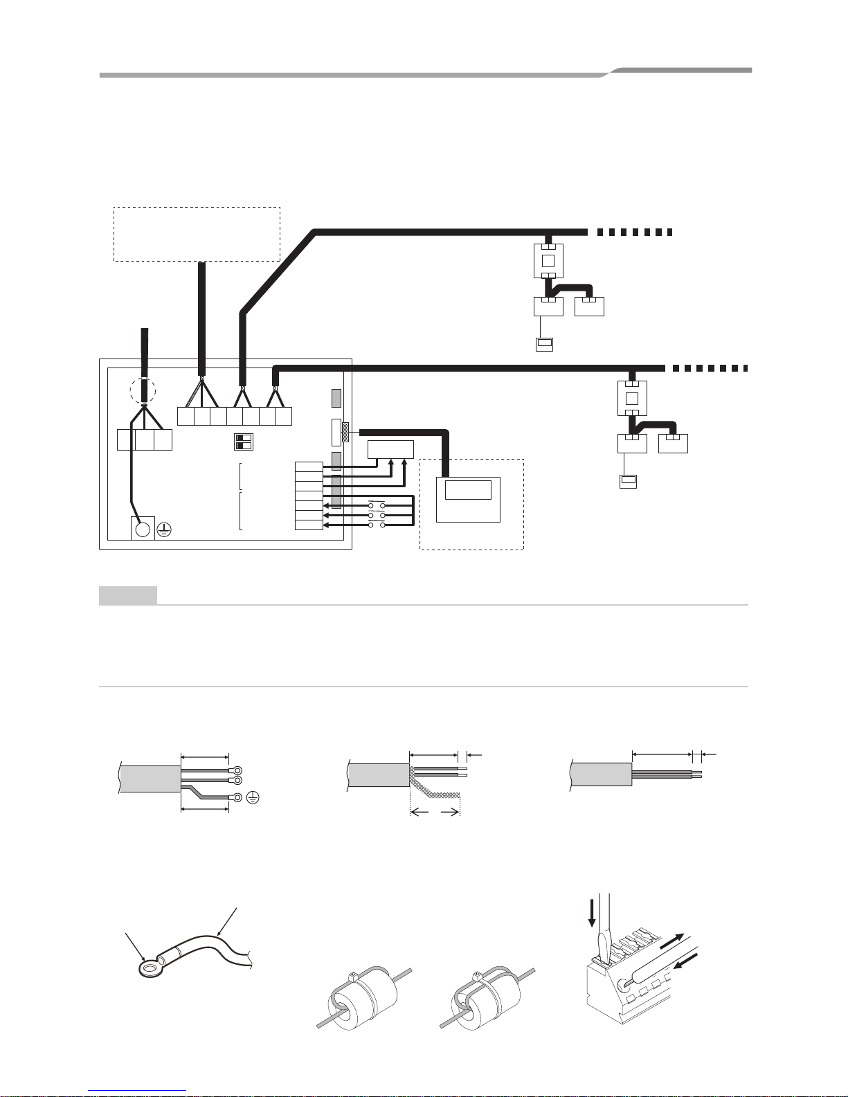
4 CONNECTION OF POWER CABLES/SIGNAL
WIRES/EARTH WIRES
Connect power cables, signal wires, and earth wires to the specified terminals on the terminal block.
NOTE
• TCC-LINK does not have polarity.
• RS-485 has a polarity. Connect A(+) to A(+) and connect B(-) to B(-).
• For TCC-LINK, connect the shield wire to the ground on the air conditioner side (single-point grounding).
• For RS-485, connect the shield wire to the ground on the Compliant Manager side (single-point grounding).
Common (Out)
Alarm
Common (In)
Fire alarm
All Start
All Stop
RunStatus Output
ON
Control Input
12
FG B (-)A (+)
U2/U4 U1/U3 U2/U4 U1/U3
FG N
COM-DO
DO2
DO1
COM-DI
DI3
DI2
DI1
TIMER
L
Power Supply
220-240VAC
Optional for BMSCM1280FTLE only
Energy Monitoring Interface
Digital I/O Interface
TCC-LINK main Bus (LINE2)
Outdoor Unit
Indoor Unit
Remoto controller
TCC-LINK main Bus (LINE1)
Outdoor Unit
Indoor Unit
Remoto
controller
Schedule Timer
RS-485
*1 Secure the power cable with the clamp in the case.
*1
Optional
N
L
20
80
15 10
35
20 10
Length of stripped power cable
Length of stripped TCC-LINK
and RS-485 communication wire
Length of stripped digital Input/
Output communication wire
Be sure to attach the supplied clamp filter to
the communication wire.
* When attaching the clamp filter, be sure to
pass the communication wire twice through
the clamp filter as shown below. Then
fasten the communication wire with the
supplied cable tie-wrap.
TCC-LINK wire
RS-485 wire
LAN cable
Remove and insert the wire
while pressing the upper button
with a screwdriver.
Power wire
Round pressure
terminal
Attach a round pressure
terminal to the end of each wire
of the power cable.
5-EN
Page 7
–7–
Compliant Manager
Installation Manual
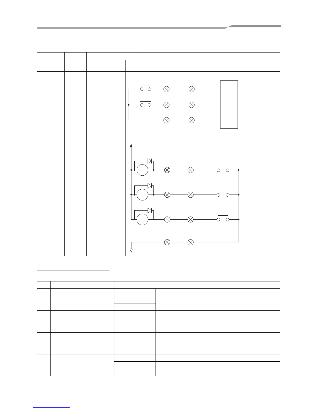
<Connections to External Equipment>
<Specifications for Wiring>
Use the following materials to connect signal lines and power lines (procured on site)
Designation
Input/
Output
item
Compliant Manager side External equipment side
Input/output
conditions
Terminal name
Demarcation
terminal
Example of
circuit
Input/output
conditions
Digital
input/output
terminals
Status
output
Alarm output
Run output
Non-voltage “A”
contacts
Static
(Relay output)
Allowable contact
voltage/current 30
VDC, 0.3 A
Wiring length:
100 m or less
Control
input
All stop input
All start input
Fire alarm input
Voltage-applied
“A” contacts
All stop:
Pulse or static
All start:
Pulse or static
Fire alarm: Static
(Photocoupler
input)
* Select non-
voltage contacts
that allow minute
current (12V,
1mA)
Pulse width:
300 ms or more
Wiring length:
100 m or less
No Line Description
1 For TCC-LINK
Type 2-wire sheld cord
Wire size
1.25mm², 1000m max. (total length including
2.00mm², 2000m max. air conditioner area)
Length
2 For RS-485
Type 2-wire sheld cord
Wire size
1.25mm², 500m max. (total length)
Length
3For Power
Type
H07 RN-F or 245IEC66
0.75mm², 50m max.
Wire size
Length
4
For Digital Input/Output
connection
Type 2-wire cord
Wire size
0.3mm², 100m max.
Length
0.4 to 1.2 Ø
Alarm
Run
Output common
Digital
input
+12V
COM
0.4 to 1.2 Ø
All stop (+)
Fire alarm (+)
All start (+)
Input
common (–)
(Pulse or static)
(Pulse or static)
(Static)
6-EN
Page 8
–8–
Compliant Manager
Installation Manual
5 MODE SETTING FOR THE CONTROLLER
Operation mode
Use SW1-<6> for the operation mode setting.
Control group selection
Either simultaneous mode or an arbitrary range of a line and 16 groups (1 to 16, 17 to 32, 33 to 48, and 49 to 64)
can be selectively set.
* When the control group selection is used, only the set group range is displayed.
* The control group selection is available only for one line.
OFF side: Central control mode
This Compliant Manager is used as a central control unit.
Settings with the remote controller are inhibited by the setting of the Compliant Manager.
ON side: Remote control mode
This Compliant Manager is used as a remote controller.
Settings with the Compliant Manager are inhibited by the setting of another central control unit.
DIP-SW1 DIP-SW2
<2><3><4><5><5><6>
All groups OFF OFF OFF OFF OFF OFF
LINE 1
Group 1 to 16 ON OFF OFF OFF OFF ON
Group 17 to 32 OFF
ON OFF OFF OFF ON
Group 33 to 48 OFF OFF
ON OFF OFF ON
Group 49 to 64 OFF OFF OFF
ON OFF ON
LINE 2
Group 1 to 16
ON OFF OFF OFF ON ON
Group 17 to 32 OFF
ON OFF OFF ON ON
Group 33 to 48 OFF OFF
ON OFF ON ON
Group 49 to 64 OFF OFF OFF
ON ON ON
Example:
When setting LINE 1 (group 1 to 32) in
the control group selection
ON ON OFF OFF OFF ON
7-EN
Page 9

–9–
Compliant Manager
Installation Manual
<System Configuration of the Compliant Manger>
• Each line consists of up to 64 zones and 64 groups (up to 128 zones and 128 groups in total).
• Each group number is a central control address. (Effective values 1 to 64 and 99 are unset values.)
• Default setting when shipped: One group is assigned to one zone (zone number = group number)
• Groups that can be registered in each zone must meet the following conditions.
1. Groups are connected to the same line.
2. Groups are in the same group number range when the control group selection is used.
* When the control group selection is not used ("ALL group"), all groups and zones on LINE 1 and LINE 2 can be
controlled.
* When the control group selection is used, only groups and zones in the set group range can be controlled.
• When the control group selection is used, groups and zones outside this range are not displayed and cannot
be operated.
• means the entire set group range.
• Zones can be registered and operated only within the set group range. (No groups outside the range can be
registered or operated.)
• The group control mode is available only for one line.
* Multiple group ranges can be specified by the control group setting.
(Example) When groups 33 to 48 and groups 49 to 64 are specified at the same time, a group range (groups
33 to 64) is set by the control group setting.
Gr1 Gr5 Gr8 Gr16
Gr32Gr32
Gr32Gr48
Gr2 Gr10
ZONE 39
ZONE 1
Gr17
Gr33 Gr35
Gr22 Gr25
Gr39 Gr43
Gr30
Gr45
Gr32Gr64Gr49 Gr50 Gr55 Gr58 Gr60
Gr19
ZONE 17
ZONE 33
ZONE 19 ZONE 22
ZONE 32
ZONE 64
ZONE 30
ZONE 2 ZONE 10 ZONE 16
ALL
LINE 1
LINE 2
Compliant Manager
Group
1 ~ 16
Group
17 ~ 32
Group
33 ~ 48
Group
49 ~ 64
ALL: The Compliant Manger operates as follows in combination with LINE selection.
LINE 1 ALL (All groups on LINE 1 are selected.)
LINE 2 ALL (All groups on LINE 2 are selected.)
Gr = Group
8-EN
Page 10

–10–
Compliant Manager
Installation Manual
6 SWITCHES FOR SETTING
The settings switch is installed on the rear of the Compliant Manager.
1 2 3 OFF ON ON OFF
NOT CHANGE
CENTRAL 2
ALL OFF
ALL OFF AND CENTRAL 2
ALL OFF AND CENTRAL 1
CENTRAL 1
ALL ON ALL OFF
PERMITTED ALL
INDOOR UNIT
OPERATION BY
USING RCU
2
1
Must be set
to OFF
ON
OFF
Fire alram input
switching
Synchronization of
Setting Zone data
Fire alram
Normal
Fire alram
Normal
4
SW3
ON
OFF
3
Must be set
to OFF
SW2
ON
OFF
4
Must be set
to OFF
5
LINE 2
LINE 1
7
OFF
ON
Buzzer
Control group
Selection Line
8
OFF
ON
Indicate
SW1
2 3 4 5
SW2
6
ALL groups
group 1 ~ 16
group 17 ~ 32
group 33 ~ 48
group 49 ~ 64
Control groups Selection
SW1
ON
OFF
1
SUB
MAIN
6
RCU
CENTRAL
7
SUB
MAIN
8
INHIBIT
PERMIT
Central/Individual
Sys.con
Central/RCU change
Central Control
To avoid an electric shock hazard. DO NOT touch any
terminal on the Printed Circuit Board with a metal rod a
screwdriver edge nor a bare hand when power is supplied.
State for Weekly timer
DIP-SW2
DIP-SW1
DIP-SW3
9-EN
Page 11

–11–
Compliant Manager
Installation Manual
1
ON
OFF
2 3 4 5 6 7 8
DIP-SW1
<1> Compliant Manager main/sub selection
OFF: Main
ON: Sub
Normally, this bit is set to OFF.
When two Compliant Manager units are used as a main unit and a sub
unit with the same mode setting, set this bit to OFF (Main) for one unit
and to ON (Sub) for the other unit.
<2> to <5> Control group selection
These bits specify a group range used in the control group selection.
The Compliant Manager for which control group selection is set controls
only groups within the set group range.
* To use the control group selection, set SW1-<2> to <5> and SW2-<5>
to <6>.
Control group selection SW2-<6> SW1
All groups OFF -
Group 1 ~ 16 ON <2> ON
Group 17 ~ 32 ON <3> ON
Group 33 ~ 48 ON <4> ON
Group 49 ~ 64 ON <5> ON
<6> Central control/remote controller mode selection
OFF: Central control mode
ON: Remote controller mode
Central control mode: Individual setting by remote controller can be
inhibited by Compliant Manager.
Remote controller mode: Setting by Compliant Manager is inhibited by
other centra control equipments.
<7> Central control Main/Sub selection
OFF: Main
ON: Sub
This setting is required when multiple Compliant Manager units are
used or another central control unit is used.
(1) Set this bit to OFF when one Compliant Manager unit is used.
(2) When multiple central control units are used as a main unit and sub
units, set to OFF (Main) for one unit and set to ON (Sub) for other
units.
* It is recommended that the “All groups” (control group selection
setting) be set for the central control main unit.
Factory setting: All OFF
<8> Central button enable/
disable
OFF: button operation is
permitted
ON: button operation is
inhibited
* The button is disabled in
the remote controller mode
regardless of this setting.
<DIP-SW1>
10-EN
Page 12

–12–
Compliant Manager
Installation Manual
1
ON
OFF
2 3 4 5 6 7 8
DIP-SW2
<4> Always OFF
Always set this bit to OFF.
<5> Control group Selection line
OFF: LINE 1
ON: LINE 2
* Set a line number for which the control group selection is used.
Factory setting: All OFF
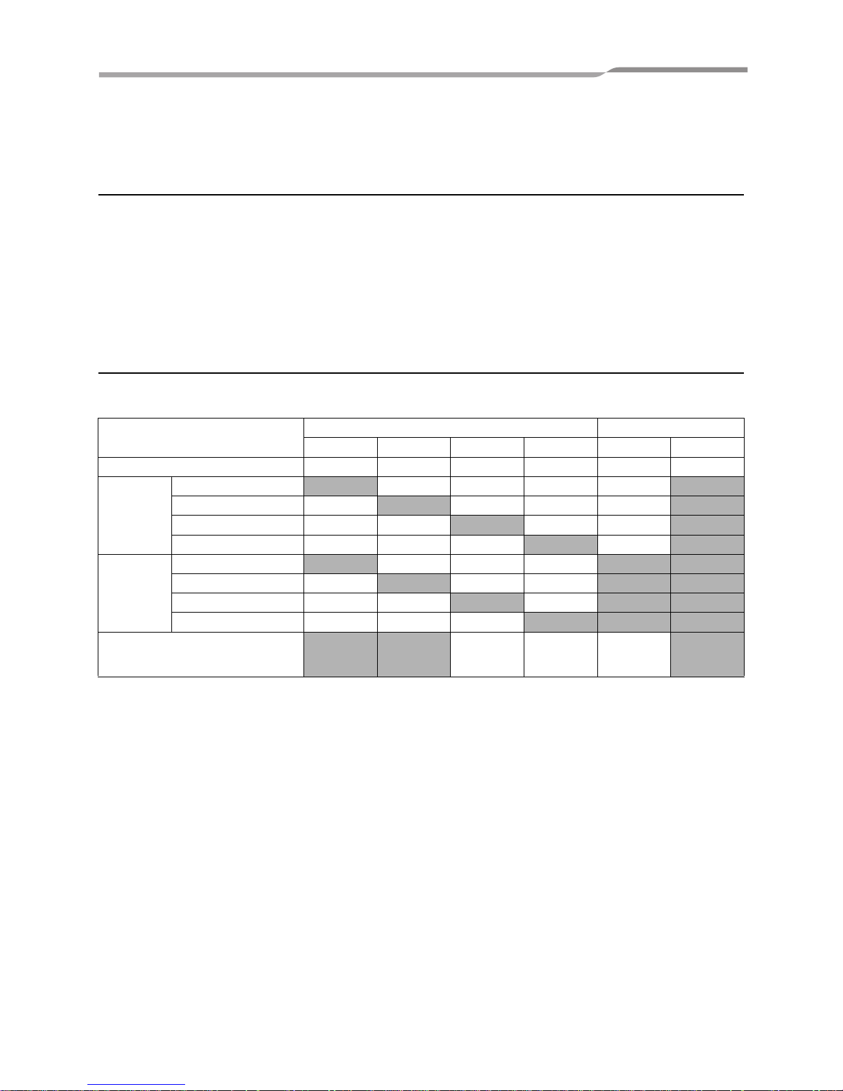
Switch No.
#1 #2 #3Central controller operation
Timer OFF → ON Timer ON → OFF
(1) All ON All OFF OFF OFF OFF
(2) No change All OFF ON OFF OFF
(3)
Individual control of all indoor
units to be permitted
All indoor units CENTRAL 1 OFF ON OFF
(4) Ditto
All OFF and all indoor units to
be CENTRAL 1
ON ON OFF
(5) Ditto All indoor units CENTRAL 2 OFF OFF ON
(6) Ditto
All OFF and all indoor units to
be CENTRAL 2
ON OFF ON
<6> Control group selection enable
OFF: Normal mode
ON: Control group selection
Set this bit to ON when the control group selection is used.
* To use the control group selection, set SW1-<2> to <5> and SW2-<5> to
<6>. For details, see the table on the previous page.
<7> Buzzer
OFF: With buzzer sound
ON: Without buzzer sound
<8> indication
OFF: Displayed
ON: Not displayed
<1> to <3> Timer input switching
These bits switch operation when the schedule timer has changed.
• Use (1) and (2) only in the remote control mode.
• When the control group selection is used, “All ON,” “All OFF” and
“all indoor units” mean those within the set group range.
<DIP-SW2>
11-EN
Page 13

–13–
Compliant Manager
Installation Manual
1
ON
OFF
2 3 4
DIP-SW3
<1> Always OFF
• Always set this bit to OFF.
<4> Fire alarm input switching
• OFF: CLOSE: Fire alarm (OPEN: Normal)
• ON: OPEN: Fire alarm (CLOSE: Normal)
COM-DI
DI3
COM-DI
DI3
(Fire alarm)(Normal)
COM-DI
DI3
COM-DI
DI3
(Fire alarm)(Normal)
Factory setting: All OFF
<2> Synchronization of Setting Zone data
OFF: With transfer
ON: Without transfer
This bit specifies whether to perform synchronous communication of Setting Zone
data between Compliant Managers.
* When this bit is set to ON (without transfer), synchronous communication is not
performed, and when zone setting is made, the data is not reflected in other
Compliant Managers.
<3> Always OFF
• Always set this bit to OFF.
<DIP-SW3>
12-EN
Page 14

–14–
Compliant Manager
Installation Manual
7 CENTRAL CONTROL ADDRESS (GROUP
NUMBER) SETTING
• Central control addresses must be assigned to all air conditioners to be controlled.
• Under the control of the Compliant Manager, central control address equals group number.
<Preparations for central control address (group number) setting>
• Turn on the power of all air conditioners.
• This Compliant Manager or a standard wired remote controller is necessary for setting central control addresses.
• Terminate the operation of air conditioners, and then set central control addresses.
* To set central control addresses with the Compliant Manager, initial communication with all connected indoor
and outdoor units must have been completed. Therefore, wait at least 10 minutes after power-on, and then start
central control address setting.
NOTE
If the address setting is made before the initial communication is completed, an address is not assigned
to some units.
• Connect terminals U1 and U2 in the outdoor unit (Header unit) to the relay connector of terminals U3 and U4.
• Set SW30-2 on the interface P.C. board of the outdoor unit (Header unit) to ON only for one system, and to OFF
for others.
* The location of SW30 is shown in the wiring diagram supplied with the outdoor unit.
<Setting central control addresses (group numbers)>
Use “manual setting from wired remote controller,” “manual setting,” or “automatic setting” to set central control
addresses.
A Manual setting from wired remote controller
Set central control addresses (group numbers) from a standard wired remote controller.
* The following setting procedure is described based on button operations of the wired remote controller RBC-
AMT32E or RBC-AMT31E.
(1) Press the button and button simultaneously for at least 4 seconds.
(Note: Do not press the button during setting.)
(2) Press the button to change the CODE No. 03.
(3) Set central control addresses (group numbers) with the buttons.
• Group numbers used for the Compliant Manager are central control addresses (DN item 03).
• The effective address range is 1 to 64. However, there must be no duplicate address on the same line.
• An address value of 99 is used as an unset address.
(4) Press the button to fix the setting.
(5) Press the button to exit the address setting mode.
* This setting procedure may vary depending on the wired remote controller model.
* Perform these steps while air conditioners are not working.
B Manual setting
Set central control addresses (group numbers) manually from the Compliant Manager.
(1) Press the button and ZONE button simultaneously for at least 4 seconds.
(CODE No. C1 flashes.)
(2) Check CODE No. C1, and then press the button.
(3) Select the line on which the unit exists and the zone and group in which addresses are to be registered with the
LINE button, ZONE and buttons, and GROUP and buttons.
For address setting when connecting a TCC-LINK adapter to the central control system, refer to this
manual and the TCC-LINK adapter installation manual.
13-EN
Page 15

–15–
Compliant Manager
Installation Manual
• When a zone is selected, group numbers registered in the zone are displayed.
• Groups whose numbers are displayed are already registered.
• Even when addresses have been registered, the registration can be cancelled with the button.
(4) Select the unit to be registered in the group selected in step (3).
• Switch refrigeration system No.1 to 31 with the button, and then switch indoor unit No.1 to 64 with the
button.
• When no system exists, indoor unit number is displayed as “- -”.
• System number 31 is for a local adapter and heat exchange ventilators. An indoor unit number is always
displayed regardless of whether the unit exists or not.
(5) Press the button to register the setting or press the button to cancel the setting.
(6) To continue registration, repeat steps (3) to (5).
(7) Press the button to terminate the address setting.
C Automatic setting
Set central control addresses automatically from the Compliant Manager.
(Central control addresses are set automatically in ascending order of unit number.)
(1) Press the button and ZONE button simultaneously for at least 4 seconds.
(CODE No. C1 flashes.)
(2) Press the SET TEMP. or button to change the CODE No. to C2.
(3) Press the button. (Central control addresses are automatically registered. This registration requires several
minutes. lights during this address setting.)
(4) goes out and the indication of C2 flashes, which shows completion of the automatic address
registration.
(5) Press the button to exit the address setting mode.
<Checking duplicate central control address>
NOTE
This function is not available for custom air conditioners.
For details, refer to the manual of the TCC-LINK adapter.
(1) Press the button and ZONE button simultaneously for at least 4 seconds.
(CODE No. C1 flashes.)
(2) Press the SET TEMP. or button to change the CODE No. C3.
(3) Press the button to start checking a duplicate central control address error. ( lights during this
check.)
(4) When goes out, the check has been completed.
* When nothing appears in the group number display area at the end of checking, no duplicate address error
has been detected.
* When a group number in the group number display area flashes at the end of checking, a duplicate address
error has been detected.
(Correct the duplicate address.)
14-EN
Page 16

–16–
Compliant Manager
Installation Manual
<Correcting duplicate address>
Correct the duplicate address detected through the check using the following procedure.
(1) When the duplicate address check has been completed, select CODE No. C1 with the SET TEMP. or
button.
(2) Press the button.
(3) The number of group in which the error has been detected flashes.
Select the flashing group number to be corrected with the GROUP or button.
(4) Press the button to clear the set incorrect central control address.
After that, set a correct central control address.
(5) Press the button to terminate the duplicate address correction.
15-EN
Page 17

–17–
Compliant Manager
Installation Manual
8 ZONE SETTING
Register groups in a zone or cancel them.
(1) Change the mode to the zone setting mode.
• Press the button, button, and ZONE button simultaneously for at least 4 seconds.
(The displayed zone number flashes and the Compliant Manager enters the zone setting mode. Indicates
CODE No. “E1”.)
(2) Select the zone to be set.
• Select the zone number to be set with the ZONE or button, and then press the button to fix the
selection.
(When the selection has been fixed, the selected zone number flashes.)
• When selection of zone has been fixed, the marks of the group numbers registered in the zone light up.
(3) Change registration of groups in a zone.
Register groups in a zone.
1. Select the group number to be set with the GROUP or button. Pressing the SET TEMP. or
button skips the group number by +16 or by -16.
2. Press the button.
The marks of the registered group numbers light up. (
→ )
3. Pressing the button restores the state before the button is pressed.
4. To continue registration of groups, repeat this procedure from the beginning.
NOTE
No zone data has been stored at this time. If the ZONE or button is pressed before the registration
change is fixed, the set content for registration change is discarded.
(4) Fix the registration change.
Press the button. The set content for registration change is stored in the memory.
* After the memory write operation has been completed, the Compliant Manager exits the zone setting mode.
16-EN
Page 18

–18–
Compliant Manager
Installation Manual
9 CHANGING RETURN-BACK TIME/
TEMPERATURE SETTINGS
Return-back time and return-back temperature (CODE No. settings) can be changed using the following
procedure.
NOTE
Do not change the data of CODE No. 0A and the following item codes to prevent the remote controller from
malfunctioning.
Changing settings
The following shows an example of changing the time (factory setting) in the case of return-back 1 heating from 30
minutes to 45 minutes.
(1) Change the mode to the CODE No. setting change mode.
Press the , , and ZONE buttons simultaneously for at least 4 seconds.
( and CODE No. flash.)
(2) Set the data of the CODE No..
1. Change the CODE No. to “02” with the SET TEMP. or button.
2. Change the set data to “045” with the GROUP or button.
( and CODE No. are still flashing.)
3. Press the button to determine the data. and CODE No. change to lighting.
4. To continuously change other settings, repeat steps 1 to 3 above.
NOTE
At this time, the entered data of the selected CODE No. has not been saved yet.
(3) Determine the change.
Press the button to write the updated data in the memory of the remote controller.
* When the data has completely been written in the memory, the CODE No. setting change mode is exited.
CODE
No.
Item
Data
Factory setting Setting range
01 Return-back Enable/Disable 001 (Enabled) 000 (Disabled), 001 (Enabled)
02 Return-back 1 Time, Heating 030 (30 minutes) 1 to 60 minutes (in units of 1 minute)
03 Return-back 1 Time, Cooling 030 (30 minutes) 1 to 60 minutes (in units of 1 minute)
04 Return-back 1 Temp., Heating 018 (18°C) 18 to 29°C (in units of 1°C)
05 Return-back 1 Temp., Cooling 028 (28°C) 18 to 29°C (in units of 1°C)
06 Return-back 2 Time, Heating 030 (30 minutes) 1 to 60 minutes (in units of 1 minute)
07 Return-back 2 Time, Cooling 030 (30 minutes) 1 to 60 minutes (in units of 1 minute)
08 Return-back 2 Temp., Heating 018 (18°C) 18 to 29°C (in units of 1°C)
09 Return-back 2 Temp., Cooling 028 (28°C) 18 to 29°C (in units of 1°C)
17-EN
Page 19

–19–
Compliant Manager
Installation Manual
LINE 1
ZONE GROUP
Indoor unit
No.
Installation place ZONE GROUP
Indoor unit
No.
Installation place
133
234
335
436
537
638
739
840
941
10 42
11 43
12 44
13 45
14 46
15 47
16 48
17 49
18 50
19 51
20 52
21 53
22 54
23 55
24 56
25 57
26 58
27 59
28 60
29 61
30 62
31 63
32 64
18-EN
Page 20

–20–
Compliant Manager
Installation Manual
LINE 2
ZONE GROUP
Indoor unit
No.
Installation place ZONE GROUP
Indoor unit
No.
Installation place
133
234
335
436
537
638
739
840
941
10 42
11 43
12 44
13 45
14 46
15 47
16 48
17 49
18 50
19 51
20 52
21 53
22 54
23 55
24 56
25 57
26 58
27 59
28 60
29 61
30 62
31 63
32 64
19-EN
Page 21

–21–
Compliant Manager
Installation Manual
10TEST RUN
<Conducting a Test Run for the Compliant Manager>
• A test run is necessary to confirm that the Compliant Manager has recognized air conditioner units after the
central control address setting.
(1) Turn on the power of all connected air conditioners.
(2) Turn on the power of the Compliant Manager.
(3) Make sure that the number of air conditioners connected to each line (only main units when group control is
performed) equals the group number count displayed on the Compliant Manager.
(4) When these numbers are identical, there is no problem.
If they differ, set central control addresses again according to “Central Control Address (Group Number)
Setting.” Also make sure that there is no incorrect wiring.
<Conducting a Test Run for Air Conditioners>
(1) Press the button for at least 4 seconds. (The “TEST” indication lights in the test run mode.)
(2) Press the button and button. (Temperature cannot be set during a test run.)
(3) When the test run is completed, press the button to exit the test run mode.
11SPECIFICATIONS
Model BMS-CM1280TLE BMS-CM1280FTLE
Power supply 220-240 VAC 50/60Hz
Power consumption 3W 5W
Number of connectable indoor units (TCC-LINK) 128 Units (LINE1 64 Units, LINE2 64 Units)
Energy Monitoring Relay Interface (RS-485) 4 Units (max.)
Digital Input/Output Relay Interface 4 Units (max.)
Operating temperature 0 to 40°C to 90%RH
Dimensions -20 to +60°C (no condensation)
Mass 120 (H) × 180 (W) × 88 (D)
Weight 1.1Kg 1.2Kg
20-EN
Page 22

–22–
MEMO
21-EN
Page 23

–23– 22-EN
Page 24

DH84309201
 Loading...