

Page 1

TOSHIBA Portable Printer
B-EP Series
Key Operation Specification
First Edition: September 19, 2008
Second Edition: May 11, 2009
Page 2
< 1 >
MODIFICATION HISTORY
EAA-02466 KEY OPERATION SPECIFICATION
Date
Modified
Pages
Description
Sept. 19, 2008 – Newly published.
May 11, 2009 3 The period of time of holding down the POWER key was identified.
5, 42, 202 • The statues during communication were deleted from the LED lightening
patterns in Sections 5.3, 6.3 and 6.9. The LED indication in a low battery
state was modified.
• Buzzer volume controllability was mentioned.
8 • Regarding the startup LCD display, explanation of g Version
information/MAIN program version was added. Accordingly, the number
for the head width was changed (from g to h).
• IPL startup was deleted from Section 5.7 LCD Display at Startup.
16, 17, 210,
211
Post-print stop position setting, back feed restriction setting and strip issue
back feed setting were added to the Mode Setting Operation Example in
5.13.1 and 6.12.2.1 and the Mode Setting Items in 5.13.2 and 6.12.2.2.
31 Wireless LAN power save setting was added to <WLAN> in 5.18.3 Interface
Setting Items.
35 The LED status for the LOW BATTERY error was corrected in 5.20.
36, 38 to 40 The Ir PACKET ERROR indication was added in 5.20 and 5.23.
50, 51 In (1) of 6.6.1.2 Self-test Items, Post-print stop position setting, back feed
restriction setting and strip issue back feed setting were added to d Various
parameter values, and wireless LAN power save was added to WLAN
SETTING.
53 to 55 PAPER STOP, BF.RESTRICT, PEEL BF. and POWER SAVE were added to
the print sample in 6.6.1.2 Self-test Items. The label length was changed in
the note for the print sample for maintenance counter/parameter values and
automatic self-test. “Example” was added to (1) Automatic self-test print.
57 The count condition was changed (from 69.4 cm to 50.0 cm) for Total label
distance covered/Label distance covered of the maintenance counter in
6.6.1.3 Self-test Result Items.
59, 60, 63,
63
Values for the writable character/BASIC file/PC save/form/graphic areas in (2)
Various parameter values table in 6.6.1.3 were corrected.
Post-print stop position setting, back feed restriction setting and strip issue
back feed setting were added. Wireless LAN power save was added to
WLAN SETTING.
As NOTE 2, an explanation for the size depending on installed DBCS was
added.
59, 71 AUTO2 was added to head division setting for the 2-inch head in 6.6.1.2 and
6.6.2.2.2.
68, 69 Post-print stop position setting, back feed restriction setting, strip issue back
feed setting were added to 6.6.2.1 Mode Setting Operation Example.
73, 74 A commentary was added to 6.6.2.2.4 Linerless Setting.
76 to 78 Post-print stop position setting, back feed restriction setting and strip issue
back feed setting were added to 6.6.2.2.6, 6.6.2.2.7 and 6.6.2.2.8,
respectively.
108 Supplemental explanations (5) and (6) were added to 6.6.4.2.6 Strip Position
Fine Adjustment.
The comment “up to V1.0C” was added to explain the case where no print
position fine adjustment value was set.
Page 3
< 2 >
Date
Modified
Pages
Description
May 11, 2009
(Continued)
143 to 145 The table of values after parameter clear in 6.6.8.2.2 was changed as follows:
The value for print type (batch/strip) was changed from ”Print depending on
the sensor used” to “AUTO.”
Post-print stop position setting, back feed restriction setting and strip issue
back feed setting were added.
The writable character/BASIC /PC save/form/graphic areas were deleted.
Wireless LAN power save was added.
165 Wireless LAN power save setting was added to .6.6.9.2.5.1 Selection of
Wireless LAN Setting Items.
178
Addition and correction were made in 6.6.9.2.6 Overview of Wireless LAN
Authentication Setting.
187, 189
The section number for the Usable Channel List by Countries refereed to from
802.11b Channel Setting (6.6.9.2.6.8) and 802.11g Channel Setting
(6.6.9.2.6.10) was changed.
192 6.6.9.2.6.12 Wireless LAN Power Saving Setting was added.
205 The comment "For details, refer to the section, “6.6.1.2 Self-test Items” in
Chapter “6. SYSTEM MODE.” was added to 6.12.1.1 Self-test Operation
Example.
218, 219 An explanation for battery charging was added to the LCD description in 7.1
In Printer Power Off State of 7. Operation during Battery Charge by AC Power
Supply.
The STATUS LED ON state was added to the LED description. Condition
(2) was added.
An explanation about the LCD was added to 7.2 In Printer Power On State.
220 Section 8 “Power Save Mode” was added.
Page 4

i
TABLE OF CONTENTS
Page
1. SCOPE ......................................................................................................................................... 1
2. OUTLINE ..................................................................................................................................... 1
3. OPERATION PANEL .................................................................................................................. 1
4. GENERAL VIEW OF KEY OPERATION .................................................................................... 2
5. ONLINE MODE ............................................................................................................................ 3
5.1 GENERAL VIEW OF KEY OPERATION ................................................................................ 3
5.2 KEY FUNCTIONS .................................................................................................................. 4
5.3 LED FUNCTIONS ................................................................................................................... 5
5.4 BUZZER FUNCTION .............................................................................................................. 5
5.5 LCD FUNCTIONS .................................................................................................................. 6
5.6 PARAMETER PRINT ............................................................................................................. 7
5.6.1 Outline of Parameter Print ............................................................................................... 7
5.6.2 Parameter Print Examples ............................................................................................... 7
5.7 LCD DISPLAY AT STARTUP ................................................................................................. 8
5.7.1 LCD Display at Startup of Wireless LAN ......................................................................... 9
5.8 SETTING VALUE DISPLAY ................................................................................................... 10
5.9 IrDA SETTING VALUE DISPLAY ........................................................................................... 11
5.10 ONLINE MODE OPERATION EXAMPLE .............................................................................. 12
5.11 THRESHOLD SETTING ......................................................................................................... 13
5.11.1 Outline of Threshold Setting ............................................................................................ 13
5.11.2 Threshold Setting Operation Example ............................................................................. 13
5.12 RESET .................................................................................................................................... 15
5.13 MODE SETTING .................................................................................................................... 16
5.13.1 Mode Setting Operation Example ..................................................................................... 16
5.13.2 Mode Setting Items ........................................................................................................... 17
5.14 VARIOUS PARAMETER SETTINGS ..................................................................................... 18
5.14.1 Parameter Setting Operation Example ............................................................................. 18
5.14.2 Parameter Setting Items ................................................................................................... 20
5.15 FINE ADJUSTMENT VALUE SETTING ................................................................................. 21
5.15.1 Fine Adjustment Value Setting Operation Example ......................................................... 21
5.15.2 Fine Adjustment Value Setting Items ................................................................................ 23
5.16 DUMPING OF RECEIVE BUFFER ........................................................................................ 24
5.16.1 Receive Buffer Dumping Operation Example .................................................................. 24
5.17 BASIC EXPANSION MODE ................................................................................................... 27
5.18 INTERFACE SETTING ........................................................................................................... 28
5.18.1 Interface Setting Operation Example ............................................................................... 28
5.18.2 Display Examples by Models ........................................................................................... 29
5.18.3 Interface Setting Items ..................................................................................................... 30
Page 5

ii
Page
5.19 BASIC SETTING .................................................................................................................... 32
5.19.1 BASIC Setting Operation Example .................................................................................. 32
5.19.2 BASIC Setting Items ........................................................................................................ 34
5.20 LCD MESSAGES AND LED INDICATIONS .......................................................................... 35
5.21 CHARGE ERROR NUMBER LIST ......................................................................................... 37
5.22 LCD MESSAGE IN DIFFERENT LANGUAGES .................................................................... 38
6. SYSTEM MODE........................................................................................................................... 41
6.1 SYSTEM MODE FOR SERVICE PERSONS AND SYSTEM ADMINISTRATORS
(ALL MENU ITEMS ARE AVAILABLE.) ................................................................................ 41
6.2 KEY FUNCTIONS .................................................................................................................. 42
6.3 LED FUNCTIONS ................................................................................................................... 42
6.4 BUZZER FUNCTION .............................................................................................................. 42
6.5 LCD FUNCTIONS .................................................................................................................. 43
6.6 LCD DISPLAY AT STARTUP ................................................................................................. 44
6.6.1 Self-test ............................................................................................................................ 45
6.6.1.1 Self-test Operation Example ..................................................................................... 45
6.6.1.2 Self-test Items ........................................................................................................... 50
6.6.1.3 Self-test Result Items ................................................................................................ 57
6.6.2 Mode Setting .................................................................................................................... 68
6.6.2.1 Mode Setting Operation Example ............................................................................. 68
6.6.2.2 Mode Setting Items ................................................................................................. 70
6.6.2.2.1 Print Command Language Setting (PCL MODE) ............................................... 70
6.6.2.2.2 Head Division Setting (HEAD DIV) ..................................................................... 71
6.6.2.2.3 B-SP Series Compatibility Mode Setting (B-SP MODE) .................................... 72
6.6.2.2.4 Linerless Setting (LINERLESS) .......................................................................... 73
6.6.2.2.5 Print Type Setting (PRINT TYPE) ...................................................................... 75
6.6.2.2.6 Post-print Stop Position Setting (PAPER STOP)
* Supported on V1.0E or later. ........................................................................... 76
6.6.2.2.7 Back Feed Restriction Setting (BF.RESTRICT)
* Supported on V1.0E or later. ........................................................................... 77
6.6.2.2.8 Strip Issue Back Feed Setting (PEEL BF.) * Supported on V1.0E or later. ....... 78
6.6.3 Various Parameter Settings ............................................................................................. 79
6.6.3.1 Parameter Setting Operation Example ..................................................................... 79
6.6.3.2 Parameter Setting Items ........................................................................................... 81
6.6.3.2.1 LCD Density Setting (LCD DENSITY) ................................................................ 81
6.6.3.2.2 Character Code Setting (FONT CODE) ............................................................. 82
6.6.3.2.3 Font Zero Setting (ZERO FONT) ....................................................................... 84
6.6.3.2.4 LCD Language Setting (LCD) ............................................................................ 85
6.6.3.2.5 Control Code Setting (CODE) ............................................................................ 86
6.6.3.2.6 EURO Font Code Setting (EURO CODE) .......................................................... 88
Page 6

iii
Page
6.6.3.2.7 MaxiCode Specification Setting (MAXI CODE) .................................................. 89
6.6.3.2.8 Auto Power-off Timing Setting (AUTO OFF) ...................................................... 90
6.6.3.2.9 Power Save Mode Timing Setting (S LEEP) ....................................................... 91
6.6.3.2.10 LCD Backlight Off Timing Setting (LCD OFF) .................................................... 92
6.6.3.2.11 Automatic Print Head Check for Broken Dots At Power On Setting
(AUTO HD CHK) ................................................................................................ 93
6.6.3.2.12 Print Head Check For Broken Dots After Cover Close Setting (HEAD CHECK)
94
6.6.3.2.13 Resume Printing After Broken Dots Error Setting (HEAD ERR PRT) ................ 95
6.6.3.2.14 Feed To Top Of Feed After Cover Close Setting (FEED CHECK) .................... 96
6.6.3.2.15 Beep Volume Setting (BEEP VOL) .................................................................... 97
6.6.3.2.16 XML Setting (XML) ............................................................................................. 98
6.6.3.2.17 System Mode Password Setting (PASSWORD) ................................................ 99
6.6.3.3 System Mode Startup Method When Password Is Set ............................................ 100
6.6.4 Fine Adjustment Value Setting ......................................................................................... 101
6.6.4.1 Fine Adjustment Value Setting Operation Example ................................................. 101
6.6.4.2 Fine Adjustment Value Setting Items ....................................................................... 103
6.6.4.2.1 Feed Amount Fine Adjustment (FEED ADJ.) ..................................................... 103
6.6.4.2.2 X-coordinate Fine Adjustment (X ADJUST.) ...................................................... 104
6.6.4.2.3 Print Tone Fine Adjustment (TONE ADJ.) .......................................................... 105
6.6.4.2.4 Reflective Sensor Manual Threshold Fine Adjustment (THRESHOLD<R>) ..... 106
6.6.4.2.5 Transmissive Sensor Manual Threshold Fine Adjustment (THRESHOLD<T>) 107
6.6.4.2.6 Strip Position Fine Adjustment (PEEL ADJ.) ...................................................... 108
6.6.4.2.7 Paper Size for ESC/POS Setting (PAPER SIZE) ............................................... 109
6.6.5 Test Print .......................................................................................................................... 110
6.6.5.1 Test Print Operation Example ................................................................................... 110
6.6.5.2 Test Print Setting Items ............................................................................................ 113
6.6.5.2.1 Test Print Mode .................................................................................................. 113
6.6.5.2.2 Test Print Condition Parameter Setting (PRINT CONDITION) .......................... 115
6.6.5.2.3 Issue Count Setting (ISSUE COUNT) ................................................................ 116
6.6.5.2.4 Sensor Setting (SENSOR) ................................................................................. 117
6.6.5.2.5 Print Type Setting (BATCH/STRIP) (TYPE) ....................................................... 118
6.6.5.2.6 Label Length Setting (LABEL LEN.) ................................................................... 119
6.6.5.2.7 Paper Feed Mode Setting (PAPER) ................................................................... 120
6.6.5.3 Test Print Samples ................................................................................................... 122
6.6.6 Sensor Display/Adjustment .............................................................................................. 131
6.6.6.1 Sensor Display/Adjustment Operation Example ...................................................... 131
6.6.6.1.1 Strip Sensitivity Setting ([PEEL]) ........................................................................ 133
Page 7

iv
Page
6.6.7 Label Paper Loading Method ........................................................................................... 134
6.6.7.1 Details of Sensor Adjustment Value Display ............................................................ 135
6.6.7.2 Sensor Display/Adjustment Setting Items ................................................................ 136
6.6.7.2.1 Backlash Step Count Adjustment 1 (BACKLASH1) ........................................... 136
6.6.7.2.2 Backlash Step Count Adjustment 2 (BACKLASH2) ........................................... 137
6.6.8 RAM Clear ........................................................................................................................ 138
6.6.8.1 RAM Clear Operation Example ................................................................................ 138
6.6.8.2 RAM Clear Setting Items .......................................................................................... 139
6.6.8.2.1 NO RAM Clear (NO RAM CLEAR) ..................................................................... 139
6.6.8.2.2 Parameter Clear (PARAMETER CLEAR) .......................................................... 140
6.6.8.2.3 Maintenance Counter Clear (MAINTE.CNT CLEAR) ......................................... 145
6.6.9 Interface Setting ............................................................................................................... 150
6.6.9.1 Interface Setting Operation Example ........................................................................ 150
6.6.9.2 Interface Setting Items .............................................................................................. 153
6.6.9.2.1 IrDA Setting ........................................................................................................ 153
6.6.9.2.1.1 IrDA Communication Program Setting (PROTOCOL) ................................. 153
6.6.9.2.1.2 IrDA Baud Rate Setting (SPEED) ................................................................ 154
6.6.9.2.1.3 Printer ID Setting .......................................................................................... 154
6.6.9.2.2 USB Serial Number Setting ................................................................................ 156
6.6.9.2.3 RS-232C Setting ................................................................................................. 157
6.6.9.2.3.1 RS-232C Baud Rate Setting (SPEED) ........................................................ 157
6.6.9.2.3.2 RS-232C Parity Setting (PARITY) ............................................................... 158
6.6.9.2.4 Bluetooth Setting ................................................................................................ 159
6.6.9.2.4.1 Device Nickname for Assembly Process Test Setting................................. 159
6.6.9.2.4.2 Inquiry Scan Time Setting (INQUIRY) ......................................................... 160
6.6.9.2.4.3 Security Level Setting (SECURITY) ............................................................ 161
6.6.9.2.4.4 Inquiry/Page Scan Interval Setting (SCN INTERVAL) ................................. 162
6.6.9.2.4.5 Inquiry/Page Scan Window Setting (SCN WINDOW) ................................. 163
6.6.9.2.5 Wireless LAN Setting .......................................................................................... 164
6.6.9.2.5.1 Selection of Wireless LAN Setting Items ..................................................... 164
6.6.9.2.5.2 Wireless LAN Enable/Disable Setting (WLAN) ............................................ 166
6.6.9.2.5.3 Printer IP Address Setting (PRINTER IP ADRES) ...................................... 167
6.6.9.2.5.4 Gateway IP Address Setting (GATEWAY IP ADRES) ................................ 168
6.6.9.2.5.5 Subnet Mask Setting (SUBNET MASK) ...................................................... 169
6.6.9.2.5.6 Socket Communication Setting (SOCKET PORT) ...................................... 170
6.6.9.2.5.7 DHCP Setting (DHCP) ................................................................................. 172
6.6.9.2.5.8 WINS Setting (WINS) ................................................................................... 173
6.6.9.2.5.9 WINS Address Setting (WINS ADDRESS) .................................................. 174
6.6.9.2.5.10 LPR Setting (LPR) ....................................................................................... 175
Page 8

v
Page
6.6.9.2.5.11 Wireless LAN Standard Setting (WLAN STANDARD) ................................ 176
6.6.9.2.6 Overview of Wireless LAN Authentication Setting ............................................. 177
6.6.9.2.6.1 Wireless LAN Connection Mode Setting (WLAN MODE) ............................ 178
6.6.9.2.6.2 ADHOC Encryption Setting (ENCRYPT) ..................................................... 179
6.6.9.2.6.3 INFRA WEP/WPA Connection Type Setting (WEP/WPA) .......................... 180
6.6.9.2.6.4 802.1X, WPA, WPA2 Connection Type Setting (AUTH) ............................. 181
6.6.9.2.6.5 802.1X, WPA, WPA2 Authentication Type Setting (SETTING) ................... 182
6.6.9.2.6.6 INFRA Encryption Setting (ENCRYPT) ....................................................... 184
6.6.9.2.6.7 Default Key Setting (DEFAULT KEY) .......................................................... 185
6.6.9.2.6.8 802.11b Channel Setting (802.11b CHANNEL) .......................................... 186
6.6.9.2.6.9 802.11b Baud Rate Setting (802.11b BAUD) .............................................. 187
6.6.9.2.6.10 802.11g Channel Setting (802.11g CHANNEL) .......................................... 188
6.6.9.2.6.11 802.11b Baud Rate Setting (802.11g BAUD) .............................................. 189
6.6.9.2.6.12 Wireless LAN Power Saving Setting (POWER SAVE)
* Supported on V1.0C or later. ..................................................................... 191
6.6.9.2.7 Usable Channel List by Countries ...................................................................... 192
6.6.10 BASIC Setting .................................................................................................................. 193
6.6.10.1 BASIC Setting Operation Example ........................................................................... 193
6.6.10.1.1 BASIC Interpreter Setting (BASIC ENABLE) ..................................................... 195
6.6.10.1.2 BASIC File Browser (FILE MAINTENANCE) ..................................................... 196
6.6.10.1.3 BASIC Trace Setting (BASIC TRACE) ............................................................... 198
6.6.10.1.4 BASIC Expansion Mode (EXPAND MODE) ....................................................... 199
6.7 SYSTEM MODE FOR USERS (AVAILABLE MENU ITEMS ARE LIMITED.) ....................... 200
6.8 KEY FUNCTIONS .................................................................................................................. 201
6.9 LED FUNCTIONS ................................................................................................................... 201
6.10 BUZZER FUNCTION .............................................................................................................. 201
6.11 LCD FUNCTIONS .................................................................................................................. 202
6.12 LCD DISPLAY AT STARTUP ................................................................................................. 203
6.12.1 Self-test ............................................................................................................................ 204
6.12.1.1 Self-test Operation Example ..................................................................................... 204
6.12.2 Mode Setting .................................................................................................................... 209
6.12.2.1 Mode Setting Operation Example ............................................................................. 209
6.12.2.2 Mode Setting Items ................................................................................................... 210
6.12.3 Fine Adjustment Value Setting ......................................................................................... 211
6.12.3.1 Fine Adjustment Value Setting Operation Example ................................................. 211
6.12.3.2 Fine Adjustment Value Setting Items ....................................................................... 213
6.12.4 Test Print .......................................................................................................................... 214
6.12.4.1 Test Print Operation Example ................................................................................... 214
6.12.4.2 Test Print Setting Items ............................................................................................ 216
Page 9

vi
Page
7. OPERATION DURING BATTERY CHARGE BY AC POWER SUPPLY ................................... 217
7.1 IN PRINTER POWER OFF STATE ........................................................................................ 217
7.2 IN PRINTER POWER ON STATE ......................................................................................... 218
8. POWER SAVE MODE ................................................................................................................. 219
8.1 SHIFTING TO POWER SAVE MODE .................................................................................... 219
8.2 WHEN A WIRELESS LAN MODULE IS CONNECTED ......................................................... 219
8.2 PRECAUTIONS ...................................................................................................................... 219
Copyright © 2008
by TOSHIBA TEC CORPORATION
All Rights Reserved
570 Ohito, Izunokuni-shi, Shizuoka-ken, JAPAN
Page 10
- 1 -
1. SCOPE
This specification describes key operations of the B-EP2 and B-EP4 portable printers (hereinafter
collectively referred to as “B-EP”) using their keys and the LCD display.
2. OUTLINE
The key operations are performed roughly in two modes: online mode and system mode. In online
mode, where the printer is connected to a host device such as a personal computer, the key operations
are performed mainly to pause or restart the printer and to display printer status messages and error
messages on the LCD. In system mode, the key operations are performed mainly to conduct a selftest and to make various parameter settings. This specification describes the key operations in these
two modes.
For explanation purposes, this specification uses English key names and LCD messages of the B-EP,
although other languages are available for key names and LCD messages.
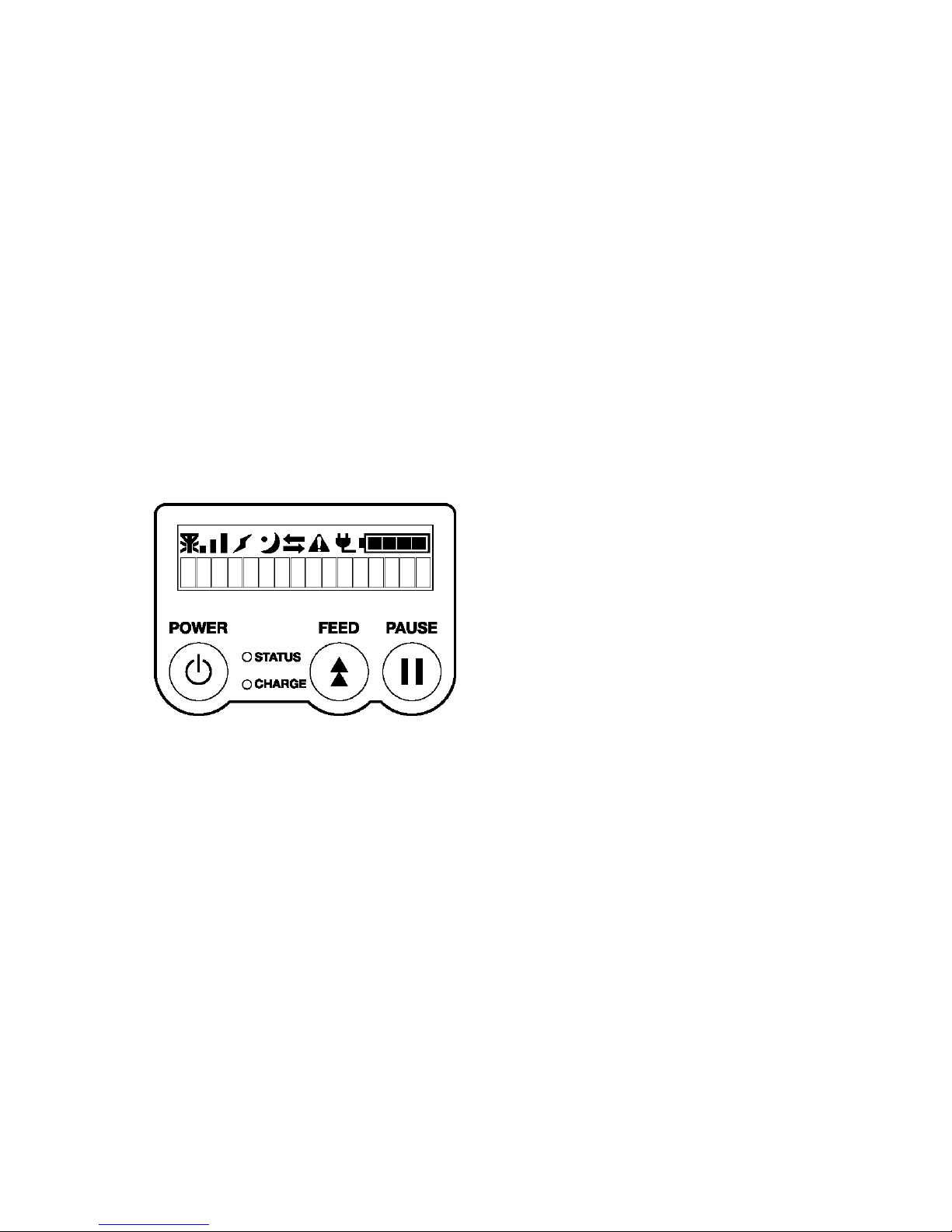
3. OPERATION PANEL
Page 11
- 2 -
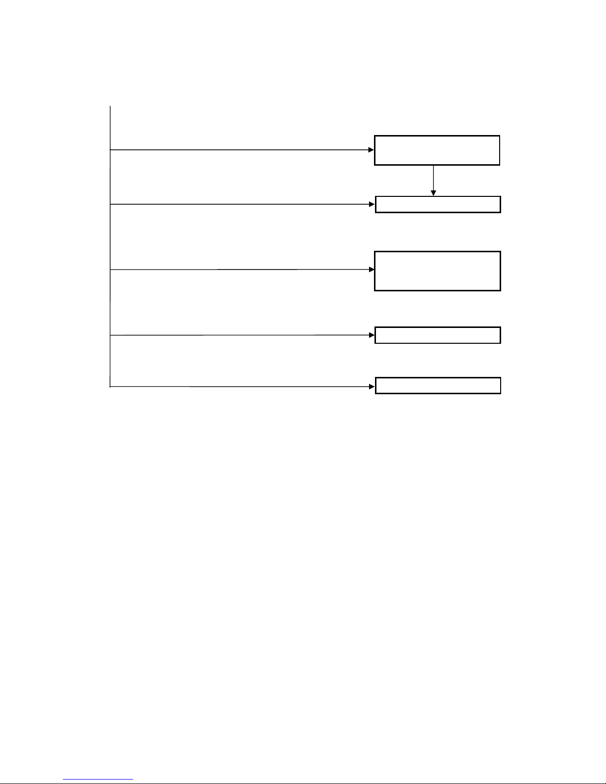
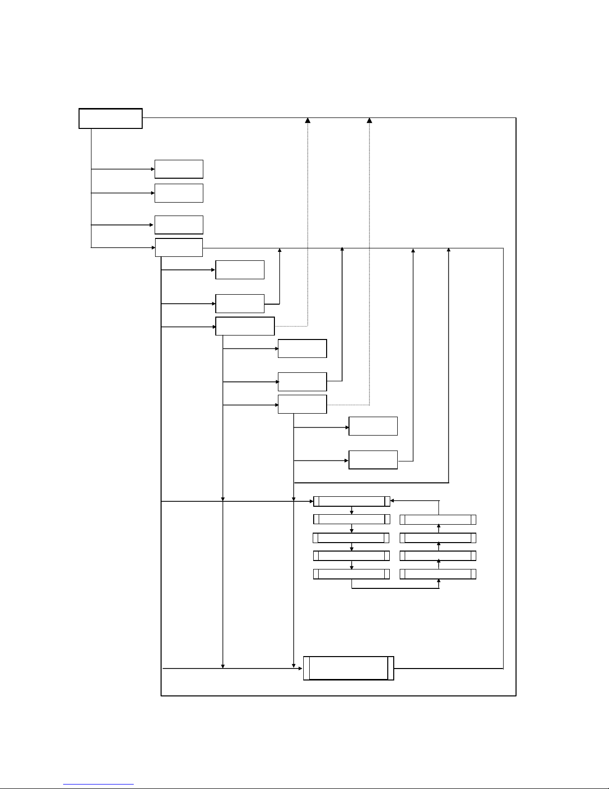
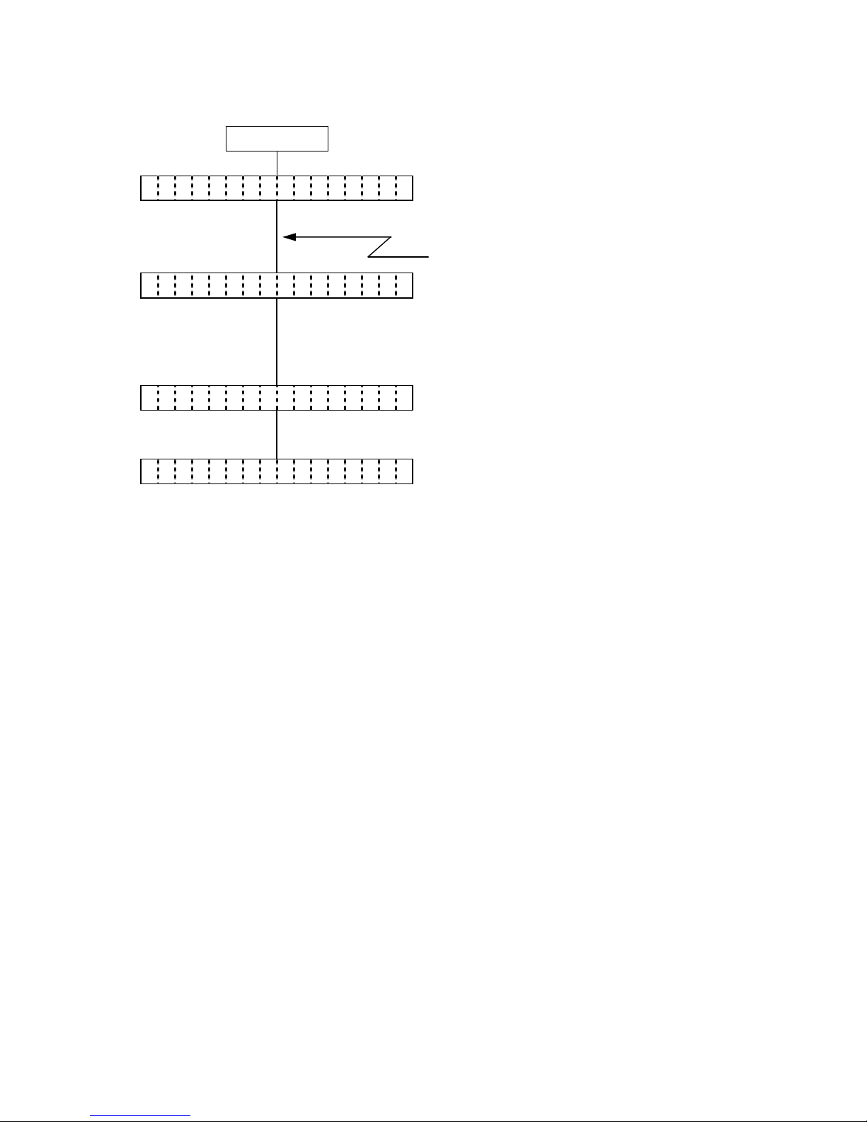
4. GENERAL VIEW OF KEY OPERATION
[Power OFF]
Press the [POWER] key
Online mode
User system mode
Download mode
System mode for service
persons and system
administrators
While holding down the [FEED] key, press the [POWEW] key for 1 sec. or
more.
While holding down the [PAUSE] key, press the [POWEW] key for 1 sec. or
more.
While holding down the [FEED] and [PAUSE] keys, press the [POWER]
key.
Printer self-test,
various parameter settings, etc.
Printer self-test,
various parameter settings, etc.
Label layout registration,
label print, etc.
Update of program and data
For details, refer to the B-EP
Series Download Tool
Operating Specification.
Press and hold down the [POWER] key until the message, “ON LINE”
a
pp
ears, then 3 sec. or more elapses.
IP address print
BD address print
Page 12
- 3 -
5. ONLINE MODE
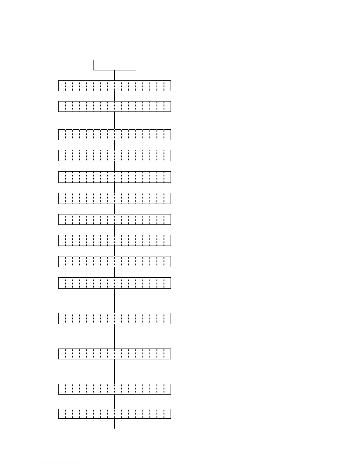
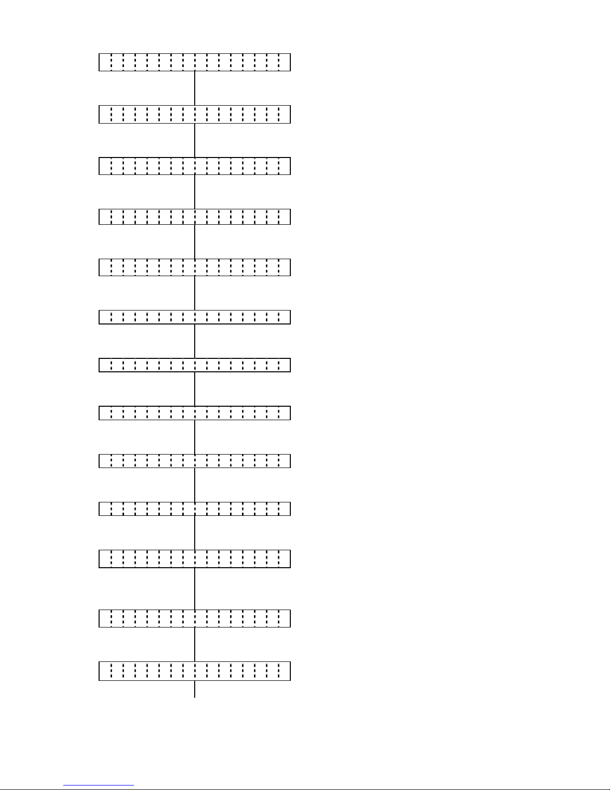
5.1 GENERAL VIEW OF KEY OPERATION
Hold down [POWER] (Release after
1.5 or more labels are fed.)
Hold down [POWER]
(3 sec. or more)
(1 sec. or more on V1.0C or later)
Hold down
[FEED]+
[PAUSE]+
[POWER]
(3 sec. or more)
Online Mode
Forced
power OFF
Power OFF
Paper feed,
Reprint
Pause
Power OFF
Paper feed
Setting value display
RS, BD, IP
Power OFF
Paper feed
IrDA setting
value dis
play
Reset
Power OFF
Paper feed
MODE SETTING
PARAMETER SET
A
DJUST SET
DUMP MODE
BASIC SETTING
I/F SETTING
SENSOR ADJ.
EXPAND MODE
THRESHOLD
Transmissive Ù Reflective
[FEED]
[PAUSE]
Hold down
[POWER] (3 sec.
or more) (1 sec. or more on V1.0C or later)
[FEED]
[POWER]
Hold down
[POWER] (3 sec.
or more) (1 sec. or more on V1.0C or later)
Hold down
[POWER] (3 sec.
or more) (1 sec. or more on V1.0C or later)
[FEED]
[POWER]
[FEED]
[POWER]
[PAUSE]
[PAUSE]
[PAUSE]
[PAUSE]
[PAUSE]
[PAUSE]
[PAUSE]
[PAUSE]
[PAUSE]
[PAUSE]
Hold down
[PAUSE]
Hold down
[FEED]
[PAUSE]
* The printer power cannot be turned off under this condition.
Press [FEED]: Moves the menu in the opposite direction
from when [PAUSE] is pressed.
Press [POWER]: Moves to each setting/process.
Hold down [POWER]: Moves to the reset menu.
* The printer power cannot be turned off under this condition.
[PAUSE]
[PAUSE]
Page 13

- 4 -
5.2 KEY FUNCTIONS
[POWER] key (1) Turns the printer power on from a power off state and initializes the printer.
(2) Performs various parameter settings.
[FEED] key: (1) Feeds or ejects 1 label. This key is also used to adjust a label to a proper
position. When the label is not properly positioned, feed 1 or 2 blank labels
using this key before printing so that the printer can start printing at the proper
position.
(2) Prints data in the image buffer on one label (depending on TPCL1 mode or
LABEL mode).
NOTE: During printing initiated by the [FEED] key, a Clear command or a
drawing command should not be sent from the host device,
otherwise the resulting printout will not be satisfactory showing an
incorrect layout. The same may happen if the [FEED] key is
pressed to start printing while data is being drawn in the image
buffer.
(3) Performs a forced strip issue in strip wait state.
(4) Programs a threshold value.
[PAUSE] key: (1) Stops printing temporarily and resumes printing.
(2) Resumes printing after clearing an error.
Key operations while the printer is in online state
y In pause state
Press [PAUSE]: Exits from a pause state.
Hold down [PAUSE]: Moves to the reset menu.
Press [FEED]: Feeds a paper.
Hold down [FEED]: Moves to the threshold setting menu.
yIn error state
Press [PAUSE]: Recovers from an error.
Hold down [PAUSE]: Moves to the reset menu.
Press [FEED]: No operation
Page 14

- 5 -
5.3 LED FUNCTIONS
[STATUS] LED: Indicates the following statuses:
(red/green/orange) Printer power, ON or OFF
Communication status of printer
Printer error
Battery level
Strip wait state
LED lighting patterns
y Power OFF/Charging in power OFF state: ................... OFF
y Power ON 1) Battery level 3 or more
In idle state ........................................... Green/ON
Strip wait state ...................................... Green/Blink
Error ...................................................... Red/Blink
2) Battery level 2 (near-low battery state)
In idle state ........................................... Orange/ON
Strip wait state ...................................... Green/Blink
Error ...................................................... Red/Blink
3) Battery level 1 (low battery state)
In idle state ........................................... Red/ON
Strip wait state ...................................... Green/Blink
Error ...................................................... Red/Blink
[CHARGE] LED: Indicates the following statuses:
(orange) Connection status of the AC adapter
Battery charge
LED lighting patterns
y Power OFF 1) AC adapter not connected .................... OFF
2) AC adapter connected
Charging ............................................... Orange/ON
Full charge ............................................ OFF
Temperature error ................................ Orange/Blink
Ambient temperature below 0 and higher than 40°C
Battery temperature below 0 and higher than 45°C
y Power ON 1) AC adapter not connected .................... OFF
2) AC adapter connected
Full charge ............................................ Orange/ON
Printing .................................................. OFF
Temperature error ................................ Orange/Blink
Ambient temperature below 0 and higher than 40°C
Battery temperature below 0 and higher than 45°C
5.4 BUZZER FUNCTION
y The buzzer sounds for 400 msec. when an error occurs and automatically stops.
y Buzzer volume (1 to 3) and ON/OFF setting can be done in system mode.
Page 15
- 6 -
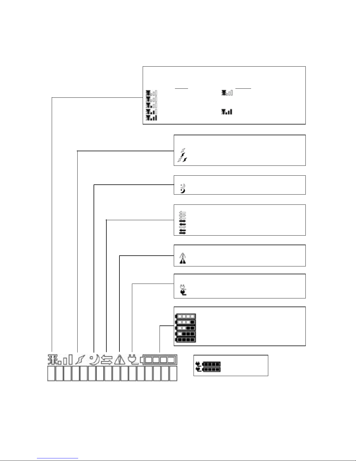
5.5 LCD FUNCTIONS
The LCD displays printer status messages.
The battery level mark and the external power source mark are updated every 5 seconds.
LCD size: 16 digits × 1 line
NOTE: When turning on the printer power on, press the [POWER] key after the battery level mark and
the external power source mark turn on, 2 to 5 seconds after the AC adopter is connected.
Otherwise, the LCD display may not be as expected or it may take a longer time for the printer
to start up.
Sleep mark: Indicates a power save status.
OFF: Normal (not in power save mode)
ON: In power save mode
Link mark: Indicates a connection status with an access point
for wireless LAN models
ON: Not connected
OFF: Connected
Blink: Roaming
Communication mark: Indicates a data communication status.
OFF: No communication
ON: Sending
ON: Receiving
ON: Sending & receiving
Error mark: Indicates a printer error status.
OFF: Not in error state
ON: In error state
External power source mark: Indicates a connection status with
an AC adaptor.
OFF: Not connected
ON: Connected
Battery level mark: Indicates a remaining battery power level.
ON: (Level1) Inoperative (low battery)
ON: (Level2) Low (near-low battery)
ON: (Level3) Medium
ON: (Level4) High
ON: (Level5) Full (full charge)
Charge status mark:
Blink: Charging
ON: Full charge
Radio intensity mark:
Indicates a radio intensity level (when wireless LAN is enabled (WLAN=ON)
for the wireless LAN model).
WLAN mode: INFRA
ADHOC
ON: Out of range ON: Paused due to wrong setting
ON: X ≤ -90 dbm
ON: -90 dbm < X ≤ -80 dbm
ON: -80 dbm < X ≤ -70 dbm ON: In operation
ON: -70 dbm < X
Page 16
- 7 -
5.6 PARAMETER PRINT
5.6.1 Outline of Parameter Print
The B-EP with the Bluetooth module or the wireless LAN module performs a parameter print
when the [POWER] key is pressed for 3 seconds or more after the printer power is turned on and
a “ON LINE” message is displayed on the LCD.
An example of parameter print for each module is given in the subsequent section.
5.6.2 Parameter Print Examples
With Bluetooth module (B-EP2/203 dpi)
With Wireless LAN module (B-EP2/203 dpi)
RF-LAN PARAMS TYPE[JPN]
IP [192.168.254.254] LPD [ON ]
GW [000.000.000.000] DHCP[ON ]
SUB[255.255.000.000] CON [INF]
SOCK[ON ][08000]
HOST [ ]
[ ]
ESSID[TOSHIBATEC ]
[ ]
MAC:0010C61CCDA900-0e-10-10-3e-
4d
WLAN Ver1.0.1
Page 17
- 8 -
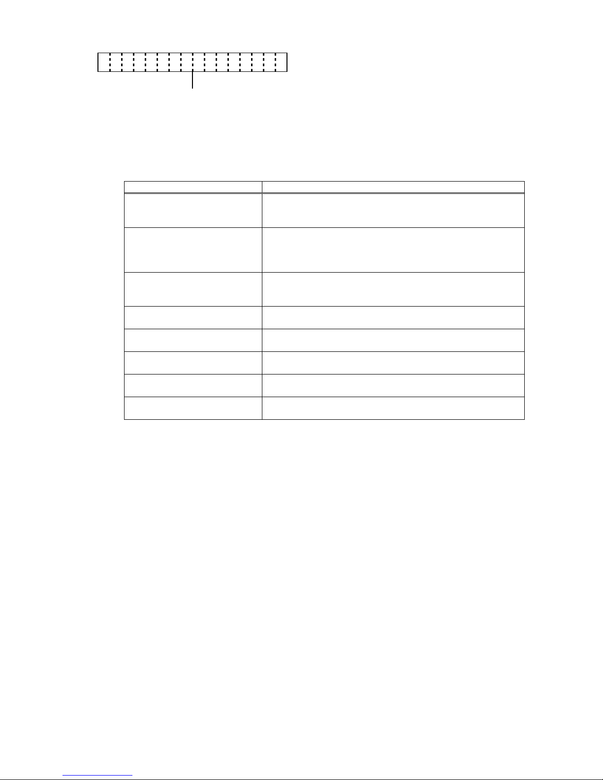
5.7 LCD DISPLAY AT STARTUP
Startup
Online
c Model 2
3
4
:
:
:
RS-232C model
Bluetooth model
Wireless LAN model
d DBCS model J
C
K
F
:
:
:
:
Japanese (Japan model)
Chinese (Global model)
Korea
No 2-byte codes
e Head density G : 203 dpi (8 dots/mm)
f Version information IPL (BOOT) program version
g Version information MAIN program version
h Head width 2 4 : : 2-inch head
4-inch head
B - E P 2DLG2J10A10B
h e c d f g
O N L I N E
Page 18

- 9 -
5.7.1 LCD Display at Startup of Wireless LAN Model
When the B-EP with the wireless LAN module is started up with the DHCP enabled, an IP
address is obtained and the LCD display will be as shown below.
When successfully connected to the DHCP server:
When failed to connect to the DHCP server:
* For the DHCP setting, refer to the section, “6.6.9.2.5.7 DHCP Setting (DHCP)”.
D H C P I N I T I A L
Connecting to the DHCP server
↓
I × × × .×××.×××.×××
Obtained an IP address
↓
O N L I N E
D H C P I N I T I A L
Connecting to the DHCP server
↓
D H C P T I M E O U T
Failed to connect to the DHCP server
↓ [POWER]
O N L I N E
Page 19
- 10 -
5.8 SETTING VALUE DISPLAY
RS-232C model
Function ON
Function OFF (Same for all interfaces)
Bluetooth model
Wireless LAN model
R S 1 1 5200bps NONE
_ _ 9 6 0 0 E V E N
_ 1 9 2 0 0 N O N E
_ 3 8 4 0 0
_ 5 7 6 0 0
1 1 5 2 0 0
* An underscore “_” indicates a space.
R S D EACTIVATE
R S
: RS-232C model
B D
: Bluetooth model
I _
: Wireless LAN model
I r
: IrDA
* An underscore “_” indicates a space.
B D _ _
BD (Bluetooth device) address display (12 byte)
* An underscore “_” indicates a space.
I × × × .×××.×××.×××
IP address set to the printer or obtained by the
DHCP server
Page 20
- 11 -
5.9 IrDA SETTING VALUE DISPLAY
When IrOBEX/IrCOMM is selected:
When TEC Protocol is selected:
I r I rOBEX/IrCOMM
I r T EC 115200bps
__9600
_19200
_38400
_57600
115200
* An underscore “_” indicates a space.
Page 21
- 12 -
5.10 ONLINE MODE OPERATION EXAMPLE
Power ON
B - E P 2 D L 2 J 1 0 1 0
* This message is displayed at a startup of IPL.
(For details, refer to Section 5.7.)
B - E P 2 D L G 2 J 1 0 1 0
* This message is displayed at a startup of main
program. (For details, refer to Section 5.7.)
O N L I N E
* This message is displayed in idle mode or normal
issue mode.
An error occurs.
N O P A P E R 5 2
* An error message is displayed when an error
occurs during printing, then the printing stops.
(The number of remaining labels to be printed is
displayed at the right of the LCD.)
[PAUSE]
Load label paper and press the [PAUSE] key.
O N L I N E
* This message is displayed after the label paper is
fed and printing resumes.
[PAUSE]
Press the [PAUSE] key.
P A U S E 5 2
* When the [PAUSE] key is pressed during printing,
this message is displayed and the printing stops.
(The number of remaining labels to be printed is
displayed at the right of the LCD.)
[PAUSE]
Press the [PAUSE] key.
O N L I N E
* This message is displayed and the printing
resumes.
NOTE: [Number of remaining labels to be printed] = [Total number of labels to be printed] -
[Number of labels already printed before an error occurred or the printer stopped temporarily]
Page 22
- 13 -
5.11 THRESHOLD SETTING
5.11.1 Outline of Threshold Setting
When a label is printed, the printer detects the gap between the labels using the transmissive
sensor, and corrects the print position automatically to obtain a constant print position.
However, when a preprinted label is used, some inks may prevent proper positioning correction.
In this case, determine the transmissive sensor threshold manually by key operation and store
the value in the non-volatile memory (EEPROM).
A constant print position can also be obtained when printing on a preprinted label since the print
position is always corrected using the threshold stored in the non-volatile memory (EEPROM) by
selecting “3: Transmissive Sensor (when using the preprinted label)” for the sensor type of the
Issue Command.
When a label is positioned by detecting the black mark on the back of the label, the reflective rate
variation of an area of the label other than the black mark may prevent the proper positioning
correction. In this case, determine the reflective sensor threshold manually by key operation
and store the value in the non-volatile memory (EEPROM).
A constant print position can also be obtained when printing on a tag since the print position is
always corrected using the threshold stored in the non-volatile memory (EEPROM) by selecting
“4: Reflective Sensor (when using a manual threshold value)” for the sensor type of the Issue
Command.
5.11.2 Threshold Setting Operation Example
Power ON
O N L I N E
(1) Idling
(2) Load the preprinted label paper.
(No particular positioning is required.)
[PAUSE]
(3) Press the [PAUSE] key.
P A U S E
(4) The printer enters a pause state.
[FEED]
(5) Hold down the [FEED] key for 3 seconds or
more while the printer is in a pause state.
T R A N S M I S S I V E
(6) “TRANSMISSIVE” is displayed, indicating the
transmissive sensor is being selected.
[POWER]
(7) Hold down the [POWER] key.
(Paper is fed until the [POWER] key is released.)
(8) Release the [POWER] key.
P A U S E
(9) The printer enters a pause state.
[FEED]
(10) Hold down the [FEED] key for 3 seconds or
more while the printer is in a pause state.
T R A N S M I S S I V E
(11) “TRANSMISSIVE” is displayed, indicating the
transmissive sensor is being selected.
[PAUSE]
(12) Press the [PAUSE] key.
R E F L E C T I V E
(13) “REFLECTIVE” is displayed, indicating the
reflective sensor is being selected.
[POWER]
(14) Hold down the [POWER] key.
(Paper is fed until the [POWER] key is released.)
Page 23

- 14 -
(15) Release the [POWER] key.
P A U S E
(16) The printer enters a pause state.
[PAUSE]
(17) Press the [PAUSE] key.
O N L I N E
(18) Idling
Command from the PC
O N L I N E
(16) The printer starts printing.
<Supplementary Explanations>
(1) When the [PAUSE] key is released within 3 seconds while the printer is paused, the
[PAUSE] key is invalid.
(2) To program the threshold, 1.5 labels or more should be fed. (If the label is not fed by the
above amount, the threshold may not be properly programmed. In this case, reprogramming
is required.)
(3) While the printer is feeding a label to program the threshold, an error detection including the
paper end or cutter error is not performed.
(4) When the proper print position is not obtained after threshold programming, the sensor may
be improperly adjusted. In this case, readjust the sensor in system mode, and program the
threshold.
When the backing paper of the label is too thick, the transmissive sensor should be
readjusted. In addition, make sure that “3: Transmissive sensor (when using the preprinted
label)” or “4: Reflective sensor (when using a manual threshold value)” is selected for sensor
type of the Feed Command and the Issue Command.
Page 24
- 15 -
5.12 RESET
Power ON
O N L I N E
(1) Idling or printing normally
[PAUSE]
(2) Press the [PAUSE] key.
P A U S E 5 2
* If the [PAUSE] key is pressed during printing, this
message is displayed and printing stops.
(The number of remaining labels to be printed is
displayed at the right of the LCD.)
[PAUSE]
(3) Hold down the [PAUSE] key for 3 seconds or
more while the printer is in a pause state.
< 1 > R E S E T
(4) The reset menu is displayed.
[POWER]
(5) Press the [POWER] key.
O N L I N E
(6) The printer returns to the same state as when
the power is turned off and on again.
<Supplementary Explanations>
(1) When the [PAUSE] key is pressed for 3 seconds or more in a recoverable error state, the
printer displays the reset menu.
(2) When the [PAUSE] key is pressed and released within 3 seconds in an error state or a
pause state, the printer resumes printing. (The reset menu is not displayed on the LCD.)
However, when the [PAUSE] key is pressed in a communication error state or a command
error state, the printer returns to the same state as when the power is turned off and on
again, whether or not the [PAUSE] key is held down for 3 seconds or more.
Page 25
- 16 -
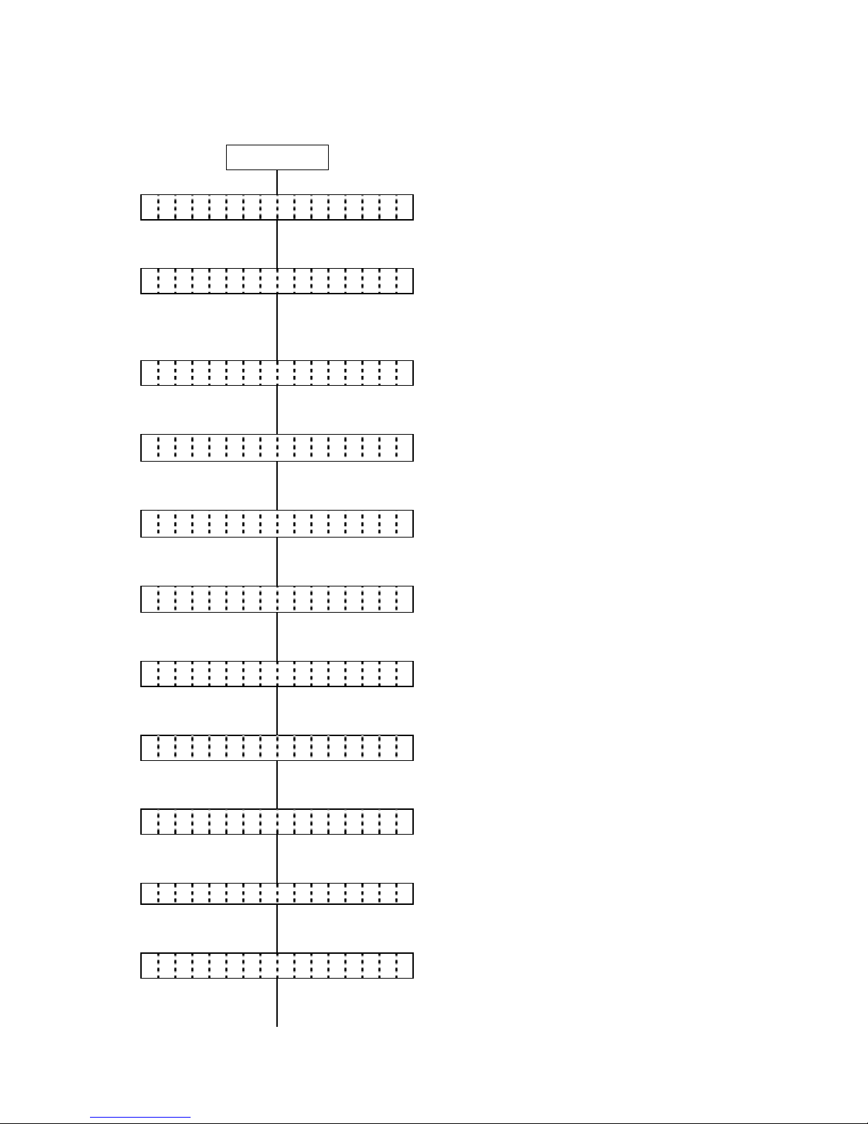
5.13 MODE SETTING
5.13.1 Mode Setting Operation Example
Power ON
O N L I N E
(1) Idling or printing normally
[PAUSE]
(2) Press the [PAUSE] key.
P A U S E
(3) “PAUSE” is displayed.
[PAUSE]
(4) Hold down the [PAUSE] key for 3 seconds or
more while the printer is in a pause state.
< 1 > R E S E T
(5) The reset menu is displayed.
[PAUSE]
(6) Press the [PAUSE] key.
< 2 > M O D E S E T T I N G
(7) System mode menu display (Mode setting)
[POWER]
(8) Press the [POWER] key.
P C L M O D E T P C L
(9) Print command language setting
[POWER]
(10) Press the [POWER] key.
H E A D D I V A U T O 1
(11) Head division setting
[POWER]
(12) Press the [POWER] key.
B - S P M O D E O F F
(13) B-SP series compatibility mode setting
[POWER]
(14) Press the [POWER] key.
L I N E R L E S S O F F
(15) Linerless setting
[POWER]
(16) Press the [POWER] key.
P R I N T T Y P E A U T O
(17) Print type setting
[POWER]
(18) Press the [POWER] key.
P A P E R S T O P C U T
(19) Post-print stop position setting
* Supported on V1.0E or later.
[POWER]
(20) Press the [POWER] key.
* Supported on V1.0E or later.
B F . R E S T R I C T O N
(21) Back feed restriction setting
* Supported on V1.0E or later.
[POWER]
(22) Press the [POWER] key.
* Supported on V1.0E or later.
P E E L B F . O F F
(23) Strip issue back feed setting
* Supported on V1.0E or later.
[POWER]
(24) Press the [POWER] key.
* Supported on V1.0E or later.
< 2 > M O D E S E T T I N G
(25) System mode menu display (Mode setting)
[POWER]
(26) Hold down the [POWER] key for 3 seconds or
more.
< 1 > R E S E T
(27) The reset menu is displayed.
[POWER]
(28) Press the [POWER] key.
Page 26
- 17 -
O N L I N E
(29) The printer returns to the same state as when
the power is turned off and on again.
5.13.2 Mode Setting Items
For details, refer to the section, “6.6.3 Various Parameter Settings” in Chapter “6. SYSTEM
MODE” (for system administrators).
Item Default
Print command language
setting
(PCL Mode)
TPCL
Head division setting
(HEAD DIV)
B-EP2:
AUTO1 (automatic selection from none, 2 or 3 division)
B-EP4:
AUTO1 (automatic selection from none, 2, 3 or 6 division)
B-SP series compatibility mode
setting
(B-SP MODE)
OFF (B-SP series compatibility mode is disabled.)
Linerless setting
(LINERLESS)
OFF (Linerless setting is disabled.)
Print type setting
(PRINT TYPE)
AUTO (automatic selection from BATCH or STRIP)
Post-print stop position setting
(PAPER STOP)
CUT (Stop at the cut position)
* Supported on V1.0E or later.
Back feed restriction setting
(BF.RESTRICT)
ON (Back feed restricted)
* Supported on V1.0E or later.
Strip issue back feed setting
(PEEL BF.)
OFF (No back feed allowed)
* Supported on V1.0E or later.
Page 27
- 18 -
5.14 VARIOUS PARAMETER SETTINGS
5.14.1 Parameter Setting Operation Example
Power ON
O N L I N E
(1) Idling or printing normally
[PAUSE]
(2) Press the [PAUSE] key.
P A U S E
(3) “PAUSE” is displayed.
[PAUSE]
(4) Hold down the [PAUSE] key for 3 seconds or
more while the printer is in a pause state.
< 1 > R E S E T
(5) The reset menu is displayed.
[PAUSE]
(6) Press the [PAUSE] key.
< 2 > M O D E S E T T I N G
(7) System mode menu display (Mode setting)
[PAUSE]
(8) Press the [PAUSE] key.
< 3 > P A R A M E T E R S E T
(9) System mode menu display
(Parameter setting)
[POWER]
(10) Press the [POWER] key.
L C D D E N S I T Y 0
(11) LCD density setting
[POWER]
(12) Press the [POWER] key.
F O N T C O D E P C - 8 5 0
(13) Character code setting
[POWER]
(14) Press the [POWER] key.
Z E R O F O N T 0
(15) Font 0 setting
[POWER]
(16) Press the [POWER] key.
L C D E N G L I S H
(17) LCD language setting
[POWER]
(18) Press the [POWER] key.
C O D E A U T O
(19) Control code setting
[POWER]
(20) Press the [POWER] key.
E U R O C O D E B 0
(21) EURO font code setting
[POWER]
(22) Press the [POWER] key.
Page 28
- 19 -
M A X I C O D E T Y P E 1
(23) MaxiCode specification setting
[POWER]
(24) Press the [POWER] key.
A U T O O F F 1 2 0 m i n
(25) Auto power-off timing setting
[POWER]
(26) Press the [POWER] key.
S L E E P 3 s e c
(27) Power save mode timing setting
[POWER]
(28) Press the [POWER] key.
L C D O F F 3 s e c
(29) LCD backlight off timing setting
[POWER]
(30) Press the [POWER] key.
A U T O H D C H K O F F
(31) Automatic print head check for broken dots
setting
[POWER]
(32) Press the [POWER] key.
H E A D C H E C K O F F
(33) Print head check for broken dots after cover
close setting
[POWER]
(34) Press the [POWER] key.
H E A D E R R P R T O F F
(35) Resume printing after broken dots error setting
[POWER]
(36) Press the [POWER] key.
F E E D C H E C K O F F
(37) Feed to top of feed after cover close setting
[POWER]
(38) Press the [POWER] key.
B E E P V O L 1
(39) Beep volume setting
[POWER]
(40) Press the [POWER] key.
X M L OFF
(41) XML setting
[POWER]
(42) Press the [POWER] key.
< 3 > P A R A M E T E R S E T
(43) System mode menu display
(Parameter setting)
[POWER]
(44) Hold down the [POWER] key for 3 seconds or
more.
< 1 > R E S E T
(45) The reset menu is displayed.
[POWER]
(46) Press the [POWER] key.
O N L I N E
(47) The printer returns to the same state as when
the power is turned off and on again.
Page 29
- 20 -
5.14.2 Parameter Setting Items
For details, refer to the section, “6.6.3 Various Parameter Settings” in Chapter “6. SYSTEM
MODE.”
Item Default
LCD density setting
(LCD DENSITY)
0
Character code setting
(FONT CODE)
PC-850
Font 0 setting
(ZERO FONT)
0 (without slash)
LCD language setting
(LCD)
ENGLISH
Control code setting
(CODE)
AUTO (automatic selection)
EURO font code setting
(EURO CODE)
B0
MaxiCode specification setting
(MAXI CODE)
TYPE1
Auto power-off timing setting
(AUTO OFF)
120 min.
Power save mode timing setting
(SLEEP)
3 sec.
LCD backlight off timing setting
(LCD OFF)
3 sec.
Automatic print head check for broken
dots setting
(AUTO HD CHK)
OFF (An automatic print head check for broken
dots is not performed.)
Print head check for broken dots after
cover close setting
(HEAD CHECK)
OFF (A print head check for broken dots is not
performed after the cover is closed.)
Resume printing after broken dots error
setting
(HEAD ERR PRT)
OFF (The printer does not resume printing after
a broken dots error occurs.)
Feed to top of feed after cover close
setting
(FEED CHECK)
OFF (A feed to the top of feed is not performed.)
Beep volume setting
(BEEP VOL)
1
XML setting
(XML)
OFF
Page 30
- 21 -
5.15 FINE ADJUSTMENT VALUE SETTING
5.15.1 Fine Adjustment Value Setting Operation Example
Power ON
O N L I N E
(1) Idling or printing normally
[PAUSE]
(2) Press the [PAUSE] key.
P A U S E
(3) “PAUSE” is displayed.
(4) Hold down the [PAUSE] key for 3 seconds or
more while the printer is in a pause state.
[PAUSE]
< 1 > R E S E T
(5) The reset menu is displayed.
[PAUSE]
(6) Press the [PAUSE] key.
< 2 > M O D E S E T T I N G
(7) System mode menu display (Mode setting)
[PAUSE]
(8) Press the [PAUSE] key.
< 3 > P A R A M E T E R S E T
(9) System mode menu display
(Parameter setting)
[PAUSE]
(10) Press the [PAUSE] key.
< 4 > A D J U S T S E T
(11) System mode menu display
(Fine adjustment value setting)
[POWER]
(12) Press the [POWER] key.
F E E D A D J . + 0 . 0 m m
(13) Feed amount fine adjustment setting
[POWER]
(14) Press the [POWER] key.
X A D J U S T +
0 . 0
mm
(15) X-coordinate fine adjustment setting
[POWER]
(16) Press the [POWER] key.
T O N E
A D J U S T
+0
(17) Print tone fine adjustment setting
[POWER]
(18) Press the [POWER] key.
Page 31

- 22 -
T H R E S H O L D < R > 1 . 0 V
(19) Reflective sensor manual threshold fine
adjustment setting
[POWER]
(20) Press the [POWER] key.
T H R E S H O L D < T > 1 . 4 V
(21) Transmissive sensor manual threshold fine
adjustment setting
[POWER]
(22) Press the [POWER] key.
P E E L A D J . +
0 . 0 m m
(23) Strip position fine adjustment setting
[POWER]
(24) Press the [POWER] key.
P A P E R S I Z E 1 1 4 m m
(25) Paper size for ESC/POS setting
[POWER]
(26) Press the [POWER] key.
< 4 > A D J U S T S E T
(27) System mode menu display
(Fine adjustment value setting)
[POWER]
(28) Hold down the [POWER] key for 3 seconds or
more.
< 1 > R E S E T
(29) The reset menu is displayed.
[POWER]
(30) Press the [POWER] key.
O N L I N E
(31) The printer returns to the same state as when
the power is turned off and on again.
Page 32

- 23 -
5.15.2 Fine Adjustment Value Setting Items
For details, refer to the section, “6.6.4 Various Fine Adjustment Value Setting” in Chapter “6.
SYSTEM MODE.”
Item Default
Feed amount fine adjustment setting
(FEED ADJ.)
+0.0mm
X-coordinate fine adjustment setting
(X ADJUST)
+0.0mm
Print tone fine adjustment setting
(TONE ADJ.)
+0
Reflective sensor manual threshold fine adjustment setting
(THRESHOLD<R>)
1.0V
Transmissive sensor manual threshold fine adjustment setting
(THRESHOLD<T>)
1.4V
Strip position find adjustment setting
(PEEL ADJ.)
+0.0mm
Paper size for ESC/POS setting
(PAPER SIZE)
58mm (B-EP2)
114mm (B-EP4)
Page 33

- 24 -
5.16 DUMPING OF RECEIVE BUFFER
5.16.1 Receiv e Buffer Dumping Operation Example
Power ON
O N L I N E
(1) Idling or printing normally
[PAUSE]
(2) Press the [PAUSE] key.
P A U S E
(3) “PAUSE” is displayed.
(4) Hold down the [PAUSE] key for 3 seconds or
more while the printer is in a pause state.
[PAUSE]
< 1 > R E S E T
(5) The reset menu is displayed.
[PAUSE]
(6) Press the [PAUSE] key.
< 2 > M O D E S E T T I N G
(7) System mode menu display (Mode setting)
[PAUSE]
(8) Press the [PAUSE] key.
< 3 > P A R A M E T E R S E T
(9) System mode menu display
(Parameter setting)
[PAUSE]
(10) Press the [PAUSE] key.
< 4 > A D J U S T S E T
(11) System mode menu display
(Fine adjustment value setting)
[PAUSE]
(12) Press the [PAUSE] key.
< 5 > D U M P M O D E
(13) System mode menu display
(Receive buffer dumping menu)
[POWER]
(14) Press the [POWER] key.
P R I N T O N D E M A N D
(15) Print method setting (page print)
[POWER]
(16) Press the [POWER] key.
N O W P R I N T I N G . . .
(17) Start of printing the receive buffer data
P R I N T O N D E M A N D
(18) Print method setting (page print) display
[PAUSE]
(19) Press the [PAUSE] key.
P R I N T A L L
(20) Print method setting (print all)
[POWER]
(21) Press the [POWER] key.
Page 34

- 25 -
N O W P R I N T I N G . . .
(22) Start of printing the remaining receive buffer
data
P R I N T A L L
(23) Print method setting (print all) display
[FEED]
(24) Press the [FEED] key.
< 5 > D U M P M O D E
(25) After printing is completed, the display returns
to the receive buffer dumping menu.
[POWER]
(26) Hold down the [POWER] key for 3 seconds or
more.
< 1 > R E S E T
(27) The reset menu is displayed.
[POWER]
(28) Press the [POWER] key.
O N L I N E
(29) The printer returns to the same state as when
the power is turned off and on again.
NOTE: If an error occurs when the printer is printing the data dumped from the receive buffer, the
printer displays an error message, then stops. The error is cleared by pressing the [PAUSE]
key, and the display returns to the receive buffer dumping menu “<5> DUMP MODE”.
After recovering from the error, the printer does not automatically resume printing.
Page 35

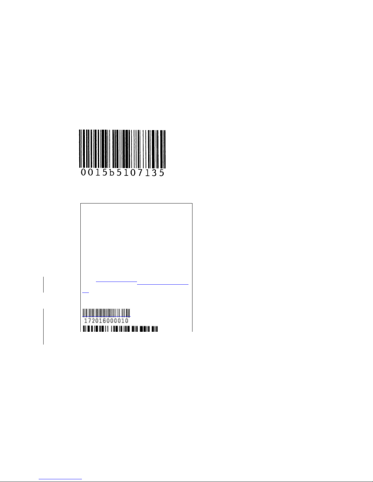
- 26 -
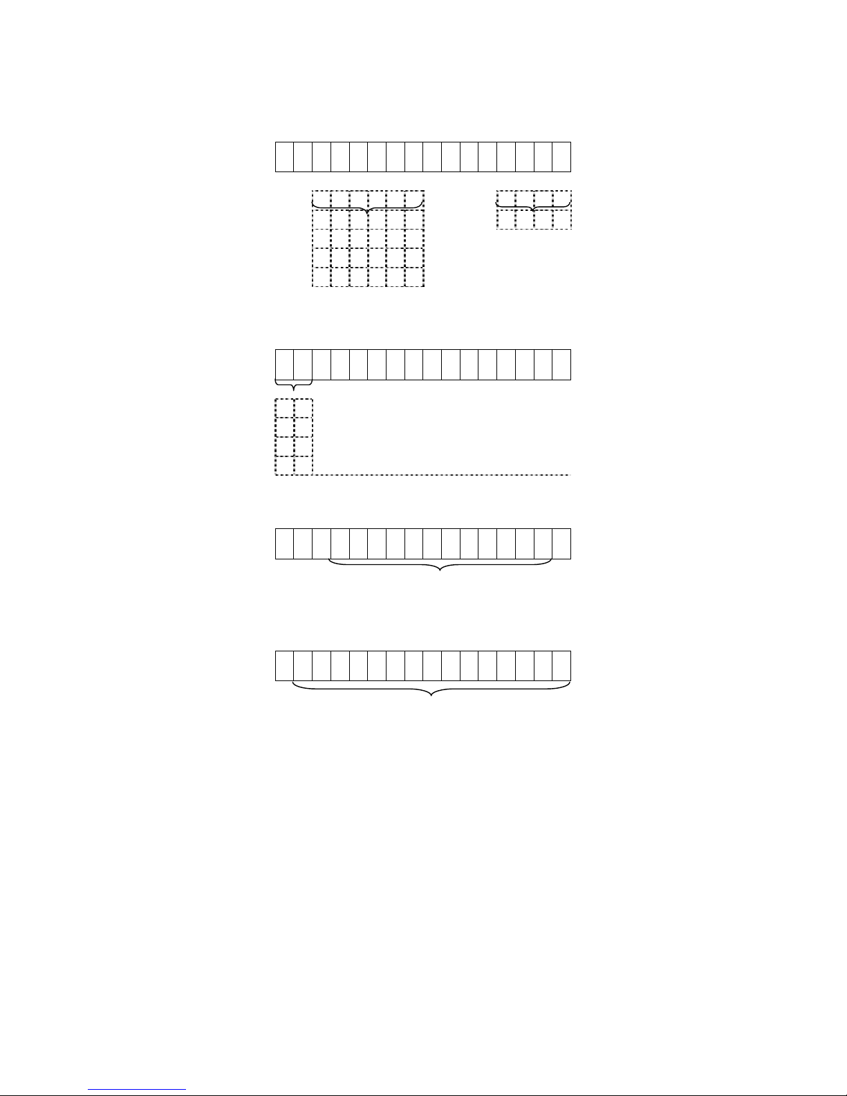
Data in the receive buffer is printed out in the format below.
B-EP2 B-EP4
Print conditions:
• Paper size: 58 mm for B-EP2, 114 mm for B-EP4
• Sensor setting: NONE
• Printable data: Data of 8 bytes per line for B-EP2, Data of 16 bytes per line for B-EP4
• Data pointed by a receive buffer write pointer is printed in bold type.
• Receive buffer size: 64 KBytes (4,096 lines of printing)
Feed direction
7B 41 58 3B 2B 30 30 30 {AX;+000
2C 2B 30 30 30 2C 2B 30 ,+000,+0
30 7C 7D 7B 44 30 37 37 0|}{D076
30 2C 31 31 30 30 2C 30 0,1100,0
37 34 30 7C 7D 7B 43 7C 740|}{C|
7D 7B 4C 43 3B 30 30 33 }{LC;003
30 2C 30 30 32 30 2C 30 0,0020,0
30 33 30 2C 30 36 36 30 030,0660
2C 30 2C 32 7C 7D 7B 4C ,0,2|}{L
43 3B 30 30 37 30 2C 30 C;0070,0
30 32 30 2C 30 30 37 30 020,0070
2C 30 36 36 30 2C 30 2C ,0660,0,
39 7C 7D 7B 4C 43 3B 30 9|}{LC;0
30 35 30 2C 30 30 32 30 050,0020
:
:
:
:
44 45 46 47 48 49 4A 7C DEFGHIJ|
7D 7B 50 43 31 30 3B 30 }{PC10;0
33 35 30 2C 30 34 30 30 350,0400
2C 31 2C 31 2C 4B 2C 30 ,1,1,K,0
30 2C 42 3D 41 42 43 44 0,B=ABCD
65 66 67 68 69 6A 6B 6C efghijkl
6D 6E 6F 70 7C 7D 7B 50 mnop|}{P
56 30 32 3B 30 33 33 30 V02;0330
2C 30 36 36 30 2C 30 32 ,0660,02
37 30 2C 30 32 35 30 2C 70,0250,
41 2C 30 30 2C 42 3D 42 A,00,B=B
7C 7D 7B 50 56 30 33 3B |}{PV03;
:
:
:
:
3B 30 39 30 30 2C 30 31 ;0900,01
38 30 2C 54 2C 48 2C 30 80,T,H,0
35 2C 41 2C 30 3D 31 32 5,A,0=12
33 34 35 36 37 38 39 30 34567890
41 42 43 44 45 7C 7D 00 ABCDE|}
00 00 00 00 00 00 00 00
00 00 00 00 00 00 00 00
00 00 00 00 00 00 00 00
00 00 00 00 00 00 00 00
00 00 00 00 00 00 00 00
00 00 00 00 00 00 00 00
00 00 00 00 00 00 00 00
:
:
7B 41 58 3B 2B 30 30 30 2C 2B 30 30 30 2C 2B 30 {AX;+000,+000,+0
30 7C 7D 7B 44 30 37 37 30 2C 31 31 30 30 2C 30 0|}{D0760,1100,0
37 34 30 7C 7D 7B 43 7C 7D 7B 4C 43 3B 30 30 33 740|}{C|}{LC;003
30 2C 30 30 32 30 2C 30 30 33 30 2C 30 36 36 30 0,0020,0030,0660
2C 30 2C 32 7C 7D 7B 4C 43 3B 30 30 37 30 2C 30 ,0,2|}{LC;0070,0
30 32 30 2C 30 30 37 30 2C 30 36 36 30 2C 30 2C 020,0070,0660,0,
39 7C 7D 7B 4C 43 3B 30 30 35 30 2C 30 30 32 30 9|}{LC;0050,0020
:
:
:
:
44 45 46 47 48 49 4A 7C 7D 7B 50 43 31 30 3B 30 DEFGHIJ|}{PC10;0
33 35 30 2C 30 34 30 30 2C 31 2C 31 2C 4B 2C 30 350,0400,1,1,K,0
30 2C 42 3D 41 42 43 44 65 66 67 68 69 6A 6B 6C 0,B=ABCDefghijkl
6D 6E 6F 70 7C 7D 7B 50 56 30 32 3B 30 33 33 30 mnop|}{PV02;0330
2C 30 36 36 30 2C 30 32 37 30 2C 30 32 35 30 2C ,0660,0270,0250,
41 2C 30 30 2C 42 3D 42 7C 7D 7B 50 56 30 33 3B A,00,B=B|}{PV03;
:
:
:
:
3B 30 39 30 30 2C 30 31 38 30 2C 54 2C 48 2C 30 ;0900,0180,T,H,0
35 2C 41 2C 30 3D 31 32 33 34 35 36 37 38 39 30 5,A,0=1234567890
41 42 43 44 45 7C 7D 00 00 00 00 00 00 00 00 00 ABCDE|}
00 00 00 00 00 00 00 00 00 00 00 00 00 00 00 00
00 00 00 00 00 00 00 00 00 00 00 00 00 00 00 00
00 00 00 00 00 00 00 00 00 00 00 00 00 00 00 00
:
:
Page 36

- 27 -
5.17 BASIC EXPANSION MODE
The BASIC expansion mode program runs under the following conditions:
y The BASIC expansion mode program is loaded.
y The BASIC interpreter setting is set to ON (enabled).
When executing the BASIC expansion mode program
< 6 > E X P A N D M O D E
(1) System mode menu display
(BASIC expansion mode)
[POWER]
(2) Press the [POWER] key.
After the BASIC expansion mode is started, LCD display and operations depend on the BASIC
expansion mode program.
NOTES:
y The BASIC expansion mode ends when the BASIC expansion program is exited.
y When the [POWER] key is pressed without the BASIC expansion mode program loaded, the
display does not change from the BASIC expansion mode menu, “<6>EXPAND MODE”.
* For details of the BASIC expansion mode, refer to the section, “Startup of System Mode Program” in
“the BASIC Interpreter Specification”.
Page 37

- 28 -
5.18 INTERFACE SETTING
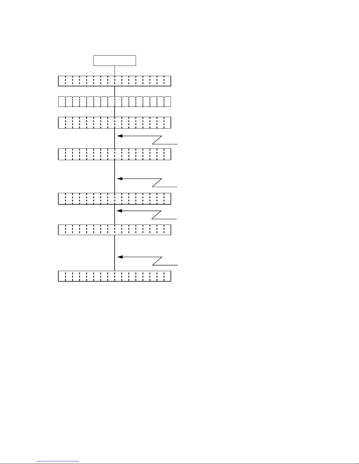
5.18.1 Interface Setting Operation Example
Power ON
O N L I N E
(1) Idling or printing normally
[PAUSE]
(2) Press the [PAUSE] key.
P A U S E
(3) “PAUSE” is displayed.
(4) Hold down the [PAUSE] key for 3 seconds or
more while the printer is in a pause state.
[PAUSE]
< 1 > R E S E T
(5) The reset menu is displayed.
[PAUSE]
(6) Press the [PAUSE] key.
< 2 > M O D E S E T T I N G
(7) System mode menu display (Mode setting)
[PAUSE]
(8) Press the [PAUSE] key.
< 3 > P A R A M E T E R S E T
(9) System mode menu display
(Parameter setting)
[PAUSE]
(10) Press the [PAUSE] key.
< 4 > A D J U S T S E T
(11) System mode menu display
(Fine adjustment value setting)
[PAUSE]
(12) Press the [PAUSE] key.
< 5 > D U M P M O D E
(13) System mode menu display
(Receive buffer dumping menu)
[PAUSE]
(14) Press the [PAUSE] key.
< 6 > E X P A N D M O D E
(15) System mode menu display
(BASIC expansion mode)
[PAUSE]
(16) Press the [PAUSE] key.
< 7 > I / F S E T T I N G
(17) System mode menu display (Interface setting)
[POWER]
(18) Press the [POWER] key.
< I r D A >
(19) IrDA setting
[PAUSE]
(20) Press the [PAUSE] key.
< U S B >
(21) USB setting
[PAUSE]
(22) Press the [PAUSE] key.
Page 38

- 29 -
< R S - 2 3 2 C >
(23) RS-232C setting
[PAUSE]
(24) Press the [PAUSE] key.
< B L U E T O O T H >
(25) Bluetooth setting
* Displayed only for the models with the
Bluetooth module
[PAUSE]
(26) Press the [PAUSE] key.
< W L A N >
(27) Wireless LAN enable/disable setting
* Displayed only for the models with the
wireless LAN module
[FEED]+[PAUSE]
(28) While holding down the [FEED] key, press the
[PAUSE] key.
< 7 > I / F S E T T I N G
(29) System mode menu display (Interface setting)
[POWER]
(30) Holding down the [POWER] key for 3 seconds
or more.
< 1 > R E S E T
(31) The reset menu is displayed.
[POWER]
(32) Press the [POWER] key.
O N L I N E
(33) The printer returns to the same state as when
the power is turned off and on again.
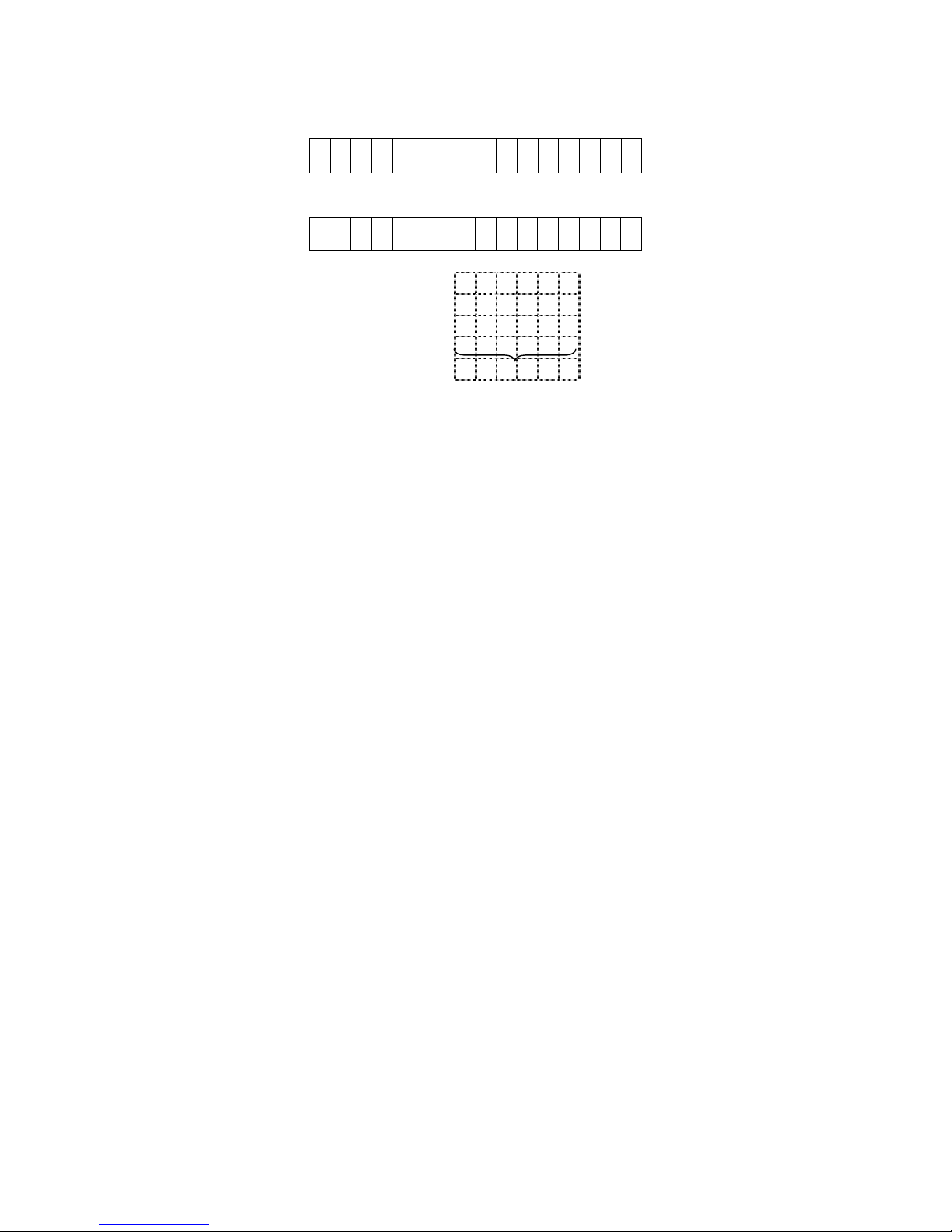
5.18.2 Display Examples by Models
• IrDA + USB + RS-232C model
<IrDA>
<USB>
<RS-232C>
• IrDA + USB + Bluetooth model
<IrDA>
<USB>
<BLUETOOTH>
• IrDA + USB + wireless LAN model
<IrDA>
<USB>
<WLAN>
Page 39

- 30 -
5.18.3 Interface Setting Items
For details, refer to the section, “6.6.9 Interface Setting” in Chapter “6. SYSTEM MODE” (for
system administrators).
<IrDA>
Item Default
IrDA protocol setting
(PROTOCOL)
IrCOMM
IrDA baud rate setting
(SPEED)
115200 (bps)
Printer ID setting
(PRINTER ID)
00001
<USB>
Item Default
USB serial number setting
(SERIAL NUMBER)
12-digit alphanumeric characters
(0 to 9, A to Z, space)
<RS-232C>
Item Default
RS-232C baud rate setting
(SPEED)
9600 (bps)
RS-232C parity setting
(PARITY)
EVEN
<BLUETOOTH>
Item Default
In-process inspection setting
(FACTORY TEST)
OFF
(Device nickname=TOSHIBA TEC BT)
Inquiry scan time setting
(INQUIRY)
EVERY
Security level setting
(SECURITY)
OFF
Inquiry/page scan interval setting
(SCN INTERVL)
2048
Inquiry/page scan window setting
(SCN WINDOW)
36
Page 40

- 31 -
<WLAN>
Item Default
Wireless LAN enable/disable setting
(WLAN)
ON
Printer IP address setting
(PRINTER IP ADRES)
192.168.254.254
Gateway IP address setting
(GATEWAY IP ADRES)
000.000.000.000
Subnet mask setting
(SUBNET MASK)
255.255.000.000
Socket communication setting
(SOCKET PORT)
ON
08000
DHCP setting
(DHCP)
OFF
WINS setting
(WINS)
OFF
WINS address setting
(WINS ADRS)
000.000.000.000
LPR setting
(LPR)
OFF
Wireless LAN standard setting
(WLAN STANDARD)
11b/g
Wireless LAN connection mode setting
(WLAN MODE)
INFRA
Wireless LAN encryption setting
(WLAN CODE)
OFF
WEP/WPA connection type setting
(WEP/WPA)
OFF
802.1X, WPA, WPA2 connection type setting
(WEP)
OFF
802.1X, WPA, WPA2 authentication type setting
(SETTING)
OFF
Default key setting
(DEFAULT KEY)
1
802.11b channel setting
(802.11b CHANNEL)
1
802.11b baud rate setting
(802.11b BAUD)
11M
802.11g channel setting
(802.11g CHANNEL)
1
802.11g baud rate setting
(802.11g BAUD)
54M
Wireless LAN power save setting
(POWER SAVE)
ON
* Supported on V1.0C or later.
Page 41

- 32 -
5.19 BASIC SETTING
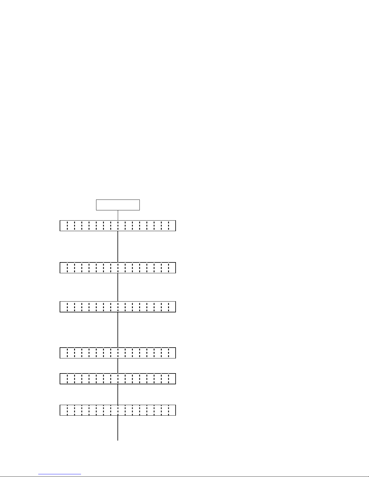
5.19.1 BASIC Setting Operation Example
Power ON
O N L I N E
(1) Idling or printing normally
[PAUSE]
(2) Press the [PAUSE] key.
P A U S E
(3) “PAUSE” is displayed.
(4) Hold down the [PAUSE] key for 3 seconds or
more while the printer is in a pause state.
[PAUSE]
< 1 > R E S E T
(5) The reset menu is displayed.
[PAUSE]
(6) Press the [PAUSE] key.
< 2 > M O D E S E T T I N G
(7) System mode menu display (Mode setting)
[PAUSE]
(8) Press the [PAUSE] key.
< 3 > P A R A M E T E R S E T
(9) System mode menu display
(Parameter setting)
[PAUSE]
(10) Press the [PAUSE] key.
< 4 > A D J U S T S E T
(11) System mode menu display
(Fine adjustment value setting)
[PAUSE]
(12) Press the [PAUSE] key.
< 5 > D U M P M O D E
(13) System mode menu display
(Receive buffer dumping menu)
[PAUSE]
(14) Press the [PAUSE] key.
< 6 > E X P A N D M O D E
(15) System mode menu display
(BASIC expansion mode)
[PAUSE]
(16) Press the [PAUSE] key.
< 7 > I / F S E T T I N G
(17) System mode menu display (Interface setting)
[PAUSE]
(18) Press the [PAUSE] key.
< 8 > B A S I C S E T T I N G
(19) System mode menu display (BASIC setting)
[POWER]
(20) Press the [POWER] key.
B A S I C E N A B L E
(21) BASIC interpreter setting
[POWER]
(22) Press the [POWER] key.
Page 42

- 33 -
B A S I C O F F
(23) BASIC setting display
[POWER]
(24) Press the [POWER] key.
F I L E M A I N T E N A N C E
(25) BASIC file browser setting
[POWER]
(26) Press the [POWER] key.
B A S I C T R A C E
(27) BASIC trace setting
[POWER]
(28) Press the [POWER] key.
T R A C E O F F
(29) BASIC trace setting display
[POWER]
(30) Press the [POWER] key.
E X P A N D M O D E
(31) BASIC expansion mode
[POWER]
(32) Press the [POWER] key.
< 8 > B A S I C S E T T I N G
(33) System mode menu display (BASIC setting)
[POWER]
(34) Holding down the [POWER] key for 3 seconds
or more.
< 1 > R E S E T
(35) The reset menu is displayed.
[POWER]
(36) Press the [POWER] key.
O N L I N E
(37) The printer returns to the same state as when
the power is turned off and on again.
NOTE: When the BASIC setting is ON, the issue mode automatically changes to TPCL mode, and
afterwards, the issue mode does not change even when the BASIC setting is set to OFF.
To select other mode, change the mode following the Mode setting procedure.
Page 43

- 34 -
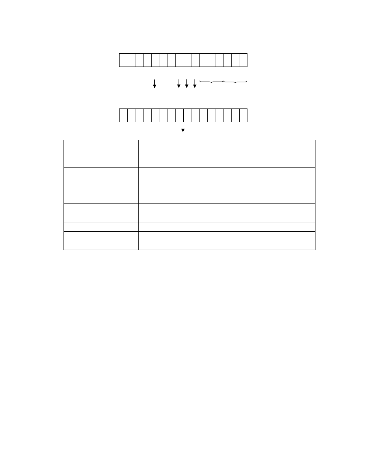
5.19.2 BASIC Setting Items
For details, refer to the section, “6.6.10 BASIC Setting” in Chapter “6. SYSTEM MODE” (for
system administrators).
Item Default
BASIC interpreter setting
(BASIC ENABLE)
BASIC OFF
BASIC file browser setting
(FILE MAINTENANCE)
Name of data stored in the BASIC file storage area
(00 to 13 + name)
BASIC trace setting
(BASIC TRACE)
TRACE OFF
BASIC expansion mode
(EXPAND MODE)
Executed when the BASIC expansion mode program
is loaded.
Page 44

- 35 -
5.20 LCD MESSAGES AND LED INDICATIONS
On the character display LCD, model and firmware version are displayed.
No.
LCD Message
LED
Indication
Printer Status
Recoverable
by the
[PAUSE] key
Acceptance
of Status
Request
and
(English)
Status
Yes/No
Reset
Commands
Yes/No
1
ON LINE
{
Online mode
- Yes
ON LINE
{
Online mode (communicating)
- Yes
LBL PRESENT ****
Strip wait
- Yes
2
COVER OPEN
{
The cover was opened in online state.
- Yes
3
PAUSE ****
z
Pause state
Yes Yes
4
COMMS ERROR
U
A parity error, overrun error, or a framing
error occurred during communication by
RS-232C.
Yes Yes
5
PAPER JAM ****
U
A paper jam occurred during paper feed.
Yes Yes
6
NO PAPER ****
U
The label has run out.
Yes Yes
7
NO PAPER
U
The label has run out after issuing the label
successfully.
Yes Yes
8
COVER OPEN ****
U
A feed or an issue was attempted with the
cover opened.
(except when the [PAUSE] key is pressed)
Yes Yes
9
HEAD ERROR
U
A broken dots error occurred in the thermal
head.
Yes Yes
10
EXCESS HEAD TEMP
U
The thermal head temperature is extremely
high (71°C or more).
No Yes
11
SAVING #### &&&&
{
In writable character or PC command save
mode
- Yes
12
FORMAT ERROR
U
An error occurred in formatting the flash
ROM on the CPU board.
No Yes
13
FLASH WRITE ERR.
U
An error occurred in writing data into the
flash ROM on the CPU board.
No Yes
14
FLASH MEM FULL
U
Saving failed due to insufficient memory
capacity of the flash ROM on the CPU
board.
No Yes
15
EEPROM ERROR
U
Data cannot be read from/written to a
backup EEPROM properly.
No No
16
LOW BATTERY
U
The battery voltage
B-EP2: 7.2V or less
B-EP4: 14.0V or less
No Yes
17
AMBIENT TEMP ERR
U
An ambient temperature is below -20°C or
over 60°C.
Yes Yes
18
BATT. TEMP ERROR
U
The battery is in a dangerous condition.
Care must be taken not to get burned.
No Yes
19
HIGH VOLT. ERROR
U
The battery is in a dangerous condition.
No Yes
Page 45

- 36 -
No.
LCD Message
LED
Indication
Printer Status
Recoverable
by the
[PAUSE] key
Acceptance
of Status
Request
and
(English)
Status
Yes/No
Reset
Commands
Yes/No
20
SYSTEM ERROR
U
When the following abnormal operations
are performed, a system error occurs:
(a) Command fetch from an odd address
(b) Access to word data at an odd address
(c) Access to long-word data at an odd
address
(d) Access to the area of 80000000H to
FFFFFFFFH in the logic space in user
mode.
(e) An undefined instruction in an area
other than a delay slot was decoded.
(f) An undefined instruction in a delay slot
was decoded.
(g) An instruction to rewrite a delay slot
was decoded.
No No
21
WAITING (BATT.)
{
The battery protection function is in
operation.
– Yes
22
WAITING (HEAD)
{
The head protection function is in
operation.
– Yes
23
WAITING (MOTOR)
{
The motor protection function is in
operation.
– Yes
24
BT INIT ERROR
{
Initialization of Bluetooth failed.
No Yes
25
BT SETTING ERROR
{
There is/are error(s) in the Bluetooth
setting.
No Yes
26
CHARGE ERROR $
{
An error occurred during battery charge.
No Yes
27
Ir PACKET ERROR
U
A block number error occurred when using
TEC Protocol.
Yes Yes
28 Display of error
command
(See NOTE 1.)
U
A command error occurred in analyzing a
command.
Yes Yes
* No.11: The LCD display changes from “SAVING #### &&&&” to “ON LINE” in B-SP series
compatibility mode.
Page 46

- 37 -
NOTE 1: When a command produces an error, 16 bytes of the command code of the erroneous
command are displayed on the LCD. (However, [LF] and [NUL] are not displayed.)
[Example 1] [ESC] PC001; 0A00,0300,2,2,A,00,B [LF] [NUL]
LCD display
PC001;0A00,0300,
[Example 2] [ESC] T02A30 [LF] [NUL]
LCD display
T02A30
[Example 3] [ESC] XR; 0200,0300,0450,1200,1[LF] [NUL]
LCD display
XR;0200,0300,045
NOTE 2: When a command error is displayed, “?” (3FH) is displayed for codes other than 20H to 7FH
and A0H to DFH.
NOTE 3: U: Blinking (red)
: ON (red)
{: ON (green or orange)
: Blinking (green)
z: OFF
****: Number of remaining labels to be printed to 9999 (in units of 1 label/tag)
####: Remaining memory capacity of PC save area in the flash memory on the CPU:
0 to 3200 (in units of 1 Kbyte)
&&&&: Remaining memory capacity of writable character/BASIC file/form/graphic storage area in
the flash memory on the CPU 0 to 3200 (in units of 1 Kbyte)
- - System error number 00 to 21
$: Charge error number 1 to 5
5.21 CHARGE ERROR NUMBER LIST
No. Details of Error Cause
1 Battery ID error Battery is not loaded or an unspecified battery is
detected.
2 Abnormal battery voltage B-EP2: 8.7V or more
B-EP4: 17.4V or more
3 Abnormal charge current
(during trickle charge)
B-EP2: 1.2A or more
B-EP4: 2.0A or more
4 Trickle charge timeout After a 90-min. trickle charge, a normal charge did not
start.
5 Abnormal charge current
(during normal charge)
B-EP2: 1.2A or more
B-EP4: 2.0A or more
Command error
Command error
Command error
Page 47

- 38 -
5.22 LCD MESSAGES IN DIFFERENT LANGUAGES
No. ENGLISH
No. GERMAN No. FRENCH
1 ON LINE 1ON LINE 1 PRETE
2 COVER OPEN 2 DECKEL OFFEN 2 ERR. CAPOT
3 PAUSE **** 3 PAUSE **** 3 PAUSE ****
4 COMMS ERROR 4 UEBERTR.-FEHLER 4 ERR. COMMUNICAT.
5 PAPER JAM **** 5 PAPIERSTAU **** 5 PB. PAPIER ****
6 NO PAPER **** 6 PAPIERENDE **** 6 FIN PAPIER ****
7 NO PAPER 7 PAPIERENDE 7 FIN PAPIER
8 COVER OPEN **** 8 DECKEL OFFEN**** 8 ERR. CAPOT ****
9 HEAD ERROR 9 KOPF DEFEKT 9 ERREUR TETE
10 EXCESS HEAD TEMP 10 KOPF UEBERHITZT 10 TETE TROP CHAUDE
11 SAVING #### &&&& 11 SP.-MOD#### &&&& 11 MEM LIB#### &&&&
12 FORMAT ERROR 12 FORMATFEHLER 12 ERREUR DE FORMAT
13 FLASH WRITE ERR. 13 FLASH FEHLER 13 ERREUR MEM FLASH
14 FLASH MEM FULL 14 FLASH ZU KLEIN 14 MEM INSUFFISANTE
15 EEPROM ERROR 15 EEPROM FEHLER 15 ERREUR EEPROM
16 LOW BATTERY 16 BATTERY SCHWACH 16 BATTERIE FAIBLE
17 AMBIENT TEMP ERR 17 TEMP. FEHLER 17 ERR.TEMP.EXTER.
18 BATT. TEMP ERROR 18 BATT.TEMP.FEHLER 18 ERR.TEMP.BATT.
19 HIGH VOLT. ERROR 19 HIGH VOLT.FEHLER 19 HIGH VOLT. ERROR
20 SYSTEM ERROR -- 20 SYSTEM FEHLER -- 20 ERR. SYSTEME -21 WAITING (BATT.) 21 WAITING (BATT.) 21 ATTENTE (BATT.)
22 WAITING (HEAD) 22 WAITING (HEAD) 22 ATTENTE (TETE)
23 WAITING (MOTOR) 23 WAITING (MOTOR) 23 ATTENTE (MOT.)
24 BT INIT ERROR 24 BT INIT ERROR 24 ERR. INIT BT
25 BT SETTING ERROR 25 BT SETTING ERROR 25 ERR. CONF BT
26 CHARGE ERROR $ 26 BATT.LADEFEHLER$ 26 ERREUR CHARGE $
27 Ir PACKET ERROR 27 Ir PACKET ERROR 27 Ir PACKET ERROR
28 LBL PRESENT **** 28 LBL ABNEHMEN**** 28 MEDIA DISPO ****
Page 48

- 39 -
No. DUTCH No. SPANISH No. ITALIAN
1 IN LIJN 1ON LINE 1 PRONTA
2 DEKSEL OPEN 2 TAPA ABIERTA 2 TESTA APERTA
3 PAUZE **** 3 PAUSA **** 3 PAUSA ****
4 COMM. FOUT 4 ERROR COMUNICACI 4 ERR. COMUNICAZ.
5 PAPIER VAST **** 5 ATASCO PAPEL**** 5 CARTA INCEP.****
6 PAPIER OP **** 6 SIN PAPEL **** 6 NO CARTA ****
7 PAPIER OP 7 SIN PAPEL 7 NO CARTA
8 DEKSEL OPEN **** 8 TAPA ABIERTA**** 8 TESTA APERTA****
9 PRINTKOP DEFECT 9 ERROR DE CABEZAL 9 ERRORE TESTINA
10 TEMP. FOUT 10 TEMP.CABEZA ALTA 10 TEMP TESTA ALTA
11 MEM #### &&&& 11 SALVAR #### &&&& 11 SALVA #### &&&&
12 FORMAAT FOUT 12 ERROR DE FORMATO 12 ERR. FORMATTAZ
13 FLASH MEM FOUT 13 ERROR ESCRITURA 13 ERR.SCRITT.CARD
14 GEHEUGEN VOL 14 MEMORIA INSUFICI 14 MEM. CARD PIENA
15 EEPROM ERROR 15 EEPROM ERROR 15 EEPROM ERROR
16 LAGE BATTERIJ 16 BATERIA BAJA 16 LOW BATTERY
17 OMGEVNG TMP FOUT 17 TEMP.AMBIEN.ALTA 17 AMBIENT TEMP ERR
18 FOUT BATT. TEMP 18 ERR.TEMP.BATERIA 18 BATT. TEMP ERROR
19 HIGH VOLT. ERROR 19 ERR.VOLT.BATERIA 19 ERRORE VOLT BATT
20 SYSTEEM FOUT -- 20 ERR DE SISTEMA-- 20 ERR. SISTEMA -21 Wachten (BATT.) 21 ESPERA: BATERIA 21 ATTESA (BATT.)
22 Wachten (HEAD) 22 ESPERA: CABEZAL 22 ATT. TESTA CALDA
23 Wachten (MOTOR) 23 ESPERA: MOTOR 23 ATT.MOTORE CALDO
24 BT INIT ERROR 24 ERR.INICIALIZ.BT 24 ERR. INIZ. B.T.
25 BT SETTING ERROR 25 ERROR CONFIG. BT 25 ERR.CONFIG. B.T.
26 OPLAADFOUT $ 26 ERROR DE CARGA $ 26 ERR.CARICANTO $
27 Ir PACKET ERROR 27 Ir PACKET ERROR 27 Ir PACKET ERROR
28 ETIKET KLAAR**** 28 ETQT PRESENT**** 28 ETICH.PRONTA****
Page 49

- 40 -
No. JAPANESE
1
2
3
4
5
6
7
8
9
10
11
12
13
14
15
16
17
18
19
20
21
22
23
24
25
26
27
28
* Japanese messages are omitted here.
Page 50

- 41 -
6. SYSTEM MODE
6.1 SYSTEM MODE FOR SERVICE PERSONS AND SYSTEM ADMINISTRATORS
(ALL MENU ITEMS ARE AVAILABLE.)
In this mode, self-test and parameter settings are performed. Described below is the key operation
procedure in system mode.
Power OFF
Password
entry
<0>SHUTDOWN
<1>DIAGNOSTIC
Invalid password
(3rd time)
[FEED] + [POWER]
Invalid password
(1st, 2nd time)
[FEED] [PAUSE]
[FEED] [PAUSE]
<2>MODE SETTING
[FEED] [PAUSE]
<3>PARAMETER SET
[FEED] [PAUSE]
<4>ADJUST SET
[FEED] [PAUSE]
<5>TEST PRINT
[FEED] [PAUSE]
<6>SENSOR ADJ.
[FEED] [PAUSE]
<7>RAM CLEAR
[FEED] [PAUSE]
<8>INTERFACE SET
<9>BASIC
[FEED] [PAUSE]
Hold down [POWER]
Hold down [POWER]
Hold down [POWER]
Hold down [POWER]
Hold down [POWER]
Hold down [POWER]
Hold down [POWER]
Hold down [POWER]
Hold down [POWER]
Press [POWER]:
Moves to each setting/process.
Hold down [POWER]:
Moves to the shutdown menu.
[FEED] or [PAUSE]: Selects an item.
[POWER]: Determines the selection.
Valid
p
assword
Page 51

- 42 -
6.2 KEY FUNCTIONS
[POWER] key (1) Determines each of various parameter settings.
[FEED] key: (1) Moves the menu.
(2) Selects a setting parameter.
[PAUSE] key: (1) Moves the menu.
(2) Selects a setting parameter.
6.3 LED FUNCTIONS
[STATUS] LED: Indicates the following statuses:
(red/green/orange) Printer power, ON or OFF
Printer error
Battery level
LED lighting patterns
y Power OFF/Charging in power OFF state: ................... OFF
y Power ON 1) Battery level 3 or more
In idle state ........................................... Green/ON
Strip wait state ...................................... Green/Blink
Error ...................................................... Red/Blink
2) Battery level 2 (near-low battery state)
In idle state ........................................... Orange/ON
Strip wait state ...................................... Green/Blink
Error ...................................................... Red/Blink
3) Battery level 1 (low battery state)
In idle state ........................................... Red/ON
Strip wait state ...................................... Green/Blink
Error ...................................................... Red/Blink
[CHARGE] LED: Indicates the following statuses:
(orange) Connection status of the AC adapter
Battery charge
LED lighting patterns
y Power OFF 1) AC adapter not connected .................... OFF
2) AC adapter connected
Charging ............................................... Orange/ON
Full charge ............................................ OFF
Temperature error ................................ Orange/Blink
Ambient temperature below 0 and higher than 40°C
Battery temperature below 0 and higher than 45°C
y Power ON 1) AC adapter not connected .................... OFF
2) AC adapter connected
Full charge ............................................ Orange/ON
Printing .................................................. OFF
Temperature error ................................ Orange/Blink
Ambient temperature below 0 and higher than 40°C
Battery temperature below 0 and higher than 45°C
6.4 BUZZER FUNCTION
y The buzzer sounds for 400 msec. when an error occurs and automatically stops.
y Buzzer volume (1 to 3) and ON/OFF setting can be done in system mode.
Page 52

- 43 -
6.5 LCD FUNCTIONS
The LCD displays printer status messages.
The battery level mark and the external power source mark are updated every 5 seconds.
LCD size: 16 digits × 1 line
NOTE: When turning on the printer power on, press the [POWER] key after the battery level mark and
the external power source mark turn on, 2 to 5 seconds after the AC adopter is connected.
Otherwise, the LCD display may not be as expected or it may take a longer time for the printer
to start up.
Not displayed in system mode.
Link mark: Indicates a connection status with an access point
for wireless LAN models
ON: Not connected
OFF: Connected
Blink: Roaming
Communication mark: Indicates a data communication status.
OFF: No communication
ON: Sending
ON: Receiving
ON: Sending & receiving
Error mark: Indicates a printer error status.
OFF: Not in error state
ON: In error state
External power source mark: Indicates a connection status with
an AC adaptor.
OFF: Not connected
ON: Connected
Battery level mark: Indicates a remaining battery power level.
ON: (Level1) Inoperative (low battery)
ON: (Level2) Low (near-low battery)
ON: (Level3) Medium
ON: (Level4) High
ON: (Level5) Full (full charge)
Charge status mark:
Blink: Charging
ON: Full charge
Radio intensity mark:
Indicates a radio intensity level (when wireless LAN is enabled (WLAN=ON)
for the wireless LAN model).
WLAN mode: INFRA
ADHOC
ON: Out of range ON: Paused due to wrong setting
ON: X ≤ -90 dbm
ON: -90 dbm < X ≤ -80 dbm
ON: -80 dbm < X ≤ -70 dbm ON: In operation
ON: -70 dbm < X
Page 53

- 44 -
6.6 LCD DISPLAY AT STARTUP
[FEED] + [POWER]
Startup of IPL
Startup of system mode
System mode menu
c DBCS model J
C
K
F
:
:
:
:
Japanese (Japan model)
Chinese (Global model)
Korea
No 2-byte codes
d Version information IPL (BOOT) program version
e Version information Main program version
f Version information SBCS version
g Version information DBCS version
h Version information HTML version
J 1 0 A 1 0 B 1 0 C 1 0 1 0 D
c d
e f g h
S Y S T E M M O D E
< 0 > S H U T D O W N
Page 54

- 45 -
6.6.1 Self-test
6.6.1.1 Self-test Operation Example
(1) Printing of maintenance counter values, various parameter values, and automatic self-test
result
Power OFF
(1) Power off state
(2) While holding down the [FEED] key, press the
[POWER] key to turn the power on.
[FEED] [POWER]
< 0 > S H U T D O W N
(3) System mode menu display (Shutdown)
[PAUSE]
(4) Press the [PAUSE] key.
< 1 > D I A G N O S T I C
(5) System mode menu display (Self-test)
[POWER]
(6) Press the [POWER] key.
M A I N T E N A N C E C O N T
(7) Print mode for maintenance counter values
and various parameter values
[POWER]
(8) Press the [POWER] key.
C H E C K I N G & P R I N T
(9) Start of check on maintenance counter values
and various parameter values
(10) The results are printed out.
< 1 > D I A G N O S T I C
(11) System mode menu display (Self-test)
[POWER]
(12) Press the [POWER] key.
A U T O D I A G N O S T I C
(13) Automatic self-test mode
[POWER]
(14) Press the [POWER] key.
C H E C K I N G & P R I N T
(15) Start of automatic self-test
(16) The results are printed out.
< 1 > D I A G N O S T I C
(17) System mode menu display (Self-test)
Page 55

- 46 -
(2) Print head check for broken dots
Power OFF
(1) Power off state
(2) While holding down the [FEED] key, press the
[POWER] key to turn the power on.
[FEED] [POWER]
< 0 > S H U T D O W N
(3) System mode menu display (Shutdown)
[PAUSE]
(4) Press the [PAUSE] key.
< 1 > D I A G N O S T I C
(5) System mode menu display (Self-test)
[POWER]
(6) Press the [POWER] key.
M A I N T E N A N C E C O N T
(7) Print mode for maintenance counter values
and various parameter values
[PAUSE]
(8) Press the [PAUSE] key.
A U T O D I A G N O S T I C
(9) Automatic self-test mode
[PAUSE]
(10) Press the [PAUSE] key.
H E A D C H E C K
(11) Print head check for broken dots mode
[POWER]
(12) Press the [POWER] key.
C H E C K I N G
(13) Start of print head check for broken dots
[When a broken dots error is not found]
N O R M A L E N D
(14) The result is displayed. (Normal end)
[PAUSE]
(15) Press the [PAUSE] key.
< 1 > D I A G N O S T I C
(16) System mode menu display (Self-test)
[When a broken
dot error is found]
H E A D E R R O R
(14’) The result is displayed. (broken dots error)
An error mark icon turns on and the red LED
blinks.
[PAUSE]
(15’) Press the [PAUSE] key.
< 1 > D I A G N O S T I C
(16’) System mode menu display (Self-test)
Page 56

- 47 -
(3) LED check
Power OFF
(1) Power off state
(2) While holding down the [FEED] key, press the
[POWER] key to turn the power on.
[FEED] [POWER]
< 0 > S H U T D O W N
(3) System mode menu display (Shutdown)
[PAUSE]
(4) Press the [PAUSE] key.
< 1 > D I A G N O S T I C
(5) System mode menu display (Self-test)
[POWER]
(6) Press the [POWER] key.
M A I N T E N A N C E C O N T
(7) Print mode for maintenance counter values
and various parameter values
[PAUSE]
(8) Press the [PAUSE] key.
A U T O D I A G N O S T I C
(9) Automatic self-test mode
[PAUSE]
(10) Press the [PAUSE] key.
H E A D C H E C K
(11) Print head check for broken dots mode
[PAUSE]
(12) Press the [PAUSE] key.
L E D C H E C K
(13) LED check mode
[POWER]
(14) Press the [POWER] key.
C H E C K I N G
(15) Start of LED check
LEDs turn on.
< 1 > D I A G N O S T I C
(16) System mode menu display (Self-test)
LED lighting pattern
STATUS LED: Turns on for 3 sec. (green)
↓
STATUS LED: Turns off
↓
STATUS LED: Turns on for 3 sec. (red)
↓ ↓
STATUS LED: Turns off CHARGE LED: Turns on for 3 sec. (orange)
↓ ↓
STATUS LED: Turns on for 3 sec. (orange) CHARGE LED: Turns off
↓
STATUS LED: Turns off
↓
Page 57

- 48 -
(4) LCD check
Power OFF
(1) Power off state
(2) While holding down the [FEED] key, press the
[POWER] key to turn the power on.
[FEED] [POWER]
< 0 > S H U T D O W N
(3) System mode menu display (Shutdown)
[PAUSE]
(4) Press the [PAUSE] key.
< 1 > D I A G N O S T I C
(5) System mode menu display (Self-test)
[POWER]
(6) Press the [POWER] key.
M A I N T E N A N C E C O N T
(7) Print mode for maintenance counter values
and various parameter values
[PAUSE]
(8) Press the [PAUSE] key.
A U T O D I A G N O S T I C
(9) Automatic self-test mode
[PAUSE]
(10) Press the [PAUSE] key.
H E A D C H E C K
(11) Print head check for broken dots mode
[PAUSE]
(12) Press the [PAUSE] key.
L E D C H E C K
(13) LED check mode
[PAUSE]
(14) Press the [PAUSE] key.
L C D C H E C K
(15) LCD check mode
[POWER]
(16) Press the [POWER] key.
(17) Start of LCD check
LCD display
All dots and backlight turn off for 3 seconds.
All dots turn on for 3 seconds. *
< 1 > D I A G N O S T I C
(18) System mode menu display (Self-test)
* When the [PAUSE] key is pressed with all LCD dots turned on, the printer stops under such condition.
Pressing the [PAUSE] key again clears the status and the system mode menu is displayed.
Page 58

- 49 -
(5) Beep check
Power OFF
(1) Power off state
(2) While holding down the [FEED] key, press the
[POWER] key to turn the power on.
[FEED] [POWER]
< 0 > S H U T D O W N
(3) System mode menu display (Shutdown)
[PAUSE]
(4) Press the [PAUSE] key.
< 1 > D I A G N O S T I C
(5) System mode menu display (Self-test)
[POWER]
(6) Press the [POWER] key.
M A I N T E N A N C E C O N T
(7) Print mode for maintenance counter values
and various parameter values
[PAUSE]
(8) Press the [PAUSE] key.
A U T O D I A G N O S T I C
(9) Automatic self-test mode
[PAUSE]
(10) Press the [PAUSE] key.
H E A D C H E C K
(11) Print head check for broken dots mode
[PAUSE]
(12) Press the [PAUSE] key.
L E D C H E C K
(13) LED check mode
[PAUSE]
(14) Press the [PAUSE] key.
L C D C H E C K
(15) LCD check mode
[PAUSE]
(16) Press the [PAUSE] key.
B E E P C H E C K
(17) Beep check mode
[POWER]
(18) Press the [POWER] key.
C H E C K I N G
(19) Start of beep check
The beep sounds for
3 sec.
< 1 > D I A G N O S T I C
(20) System mode menu display (Self-test)
Page 59

- 50 -
6.6.1.2 Self-test Items
(1) Printing of maintenance counter values and various parameter values
c Maintenance counter values
• Total label distance covered (cannot be cleared)
• Total label print distance covered (cannot be cleared)
• Label distance covered (1 to 5)
• Label print distance (1 to 5)
• RS-232C hardware error count
• System error count
d Various parameter values
[Value programmed on the PC]
• Feed amount fine adjustment value
• Print tone fine adjustment value
• Strip position fine adjustment value
[Value programmed using the keys]
• Feed amount fine adjustment value
• Print tone fine adjustment value
• Strip position fine adjustment value
• X-coordinate fine adjustment value
• Reflective sensor manual threshold fine adjustment value
• Transmissive sensor manual threshold fine adjustment value
• Print command language
• Printer ID
• Print type (BATCH/STRIP)
• Strip sensitivity
• Font zero
• Character code
• LCD language
• Control code
• EURO font code
• Automatic print head check for broken dots at power on
• MaxiCode specification
• Head division
• Print head check for broken dots after cover close
• Resume printing after broken dots error
• Feed to top of feed after cover close
• B-SP series compatibility mode
• Linerless
• Post-print stop position setting (* Supported on V1.0E or later.)
• Back feed restriction setting (* Supported on V1.0E or later.)
• Strip issue back feed setting (* Supported on V1.0E or later.)
• XML
• Beep volume
• Auto power-off timing
• Power save mode timing
• LCD backlight off timing
• Writable character storage area
• BASIC file storage area
• PC save area
• Form storage area
• Graphic storage area
• LABEL form version number
• BASIC interpreter
Page 60

- 51 -
• BASIC trace
• Shell
<<IrDA setting>>
• IrDA mode
• Maximum IrDA baud rate
<<USB setting>>
• USB serial number
<< RS-232C setting>>
• Baud rate
• Parity
<< Bluetooth setting>>
• Device nickname
• Address
• Inquiry scan time
• Inquiry/page scan interval
• Inquiry/page scan window
• Security level
<<WAN setting>>
• Wireless LAN enable/disable
• Printer IP address
• Gateway IP address
• Subnet mask
• Printer MAC address
• Socket communication
• DHCP
• DHCP ID
• DHCP host name
• ESS ID
• WINS
• WINS address
• LPR
• Wireless LAN standard
• Wireless LAN connection mode
• Encryption
• WPA authentication type
• Authentication type
• Default key
• 802.1X supplicant authentication type
• 802.11b channel
• 802.11b baud rate
• 802.11g channel
• Wireless LAN power save setting (* Supported on V1.0C or later.)
Only the setting items of interface(s) installed on the printer are printed.
Page 61

- 52 -
(2) Automatic self-test
c Model name
d Memory check
• Program area (Creation date, version, checksum)
• Boot area (Creation date, version, checksum)
• Font area (Version, checksum)
• Bit map Kanji ROM (Version, checksum)
• HTML (Creation date, version, checksum)
• EEPROM check
• SDRAM check
e Sensor check
• Thermal head thermistor
• Ambient thermistor
• Reflective sensor
• Transmissive sensor
• No paper level
• Threshold level
f Battery voltage
g Installed interface
h Loopback check
• IrDA
• RS-232C
• Bluetooth
• Wireless LAN
(When the wireless LAN is installed, version information is also displayed.)
Page 62

- 53 -
Print Samples of Self-test Result
(1) Maintenance counter values and various parameter values
TOTAL FEED 0.0m[JA]
TOTAL PRINT 0.0m
FEED 0.0m
FEED1 0.0m
FEED2 0.0m
FEED3 0.0m
FEED4 0.0m
PRINT 0.0m
PRINT1 0.0m
PRINT2 0.0m
PRINT3 0.0m
PRINT4 0.0m
232C ERR 0
SYSTEM ERR 0
[PC]
FEED +0.0mm
TONE +0step
PEEL +0.0mm
[KEY]
FEED +0.0mm
TONE +0step
PEEL +0.0mm
X ADJ. +0.0mm
THRESHOLD(R) 1.0V
THRESHOLD(T) 1.4V
PCL MODE [TPCL]
PRINTER ID [00001]
PRINT TYPE [AUTO]
PEEL LEVEL [AUTO]
FONT [0][PC-850]
MESSAGE [ENGLISH]
CODE [AUTO]
EURO CODE [B0]
AUTO HD CHK [OFF]
MAXI CODE SPEC. [TYPE1]
HEAD DIVISION [AUTO1]
HEAD ERR CHECK [OFF]
HEAD ERR PRINT [OFF]
FEED CHECK [OFF]
B-SP MODE [OFF]
LINERLESS [OFF]
PAPER STOP [CUT] *
BF.RESTRICT [ON] *
PEEL BF. [OFF] *
XML [OFF]
BEEP VOL [1]
AUTO POWER OFF [120min]
SLEEP [ 3sec]
LCD LIGHT OFF [ 3sec]
EXT CHR AREA [XXXXKB]
BASIC AREA [XXXXKB]
PC SAVE AREA [XXXXKB]
FORM AREA [XXXXKB]
GRAPHIC AREA [XXXXKB]
FORM VER. [0000000000]
[0000000000]
BASIC [OFF]
BASIC TRACE [OFF]
SHELL [OFF]
* PAPER STOP, BF.RESTRICT
and PEEL BF. are supported on
V1.0E or later.
Page 63

- 54 -
(Continued)
NOTE: Print conditions: Label length of 358 mm, direct thermal print mode, no sensors used,
one-label issue
<< IrDA >>
IrDA MODE [IrCOMM]
BAUD RATE [115200]
<< USB >>
SERIAL NUMBER [DISABLE]
[XXXXXXXXXXXX]
<< RS-232C >>
BAUD RATE [9600]
PARITY [EVEN]
<< BLUETOOTH >>
DEVICE NICKNAME
[ ]
ADDRESS [ ]
INQUIRY [EVERY]
SCAN INTERVAL [2048]
SCAN WINDOW [ 36]
SECURITY LEVEL [OFF]
<< WIRELESS LAN >>
LAN [OFF]
PRTR IP [192.168.010.020]
GATE IP [000.000.000.000]
SUBNET [255.255.255.000]
MAC [**-**-**-**-**-**]
SOCKET PORT [OFF][65535]
DHCP [OFF]
DHCP ID [ ]
[ ]
[ ]
[ ]
DHCP HOST NAME
[ ]
[ ]
ESS ID [ ]
[ ]
WINS [ON]
WINS IP [xxx.xxx.xxx.xxx]
LPR [OFF]
WLAN STANDARD [11b/g]
WLAN MODE [INFRA]
ENCRYPT [OFF]
WPA MODE [OFF]
AUTH [OFF]
DEFAULT KEY [1]
802.1X SUPPLICANT [OFF]
802.11b CHANNEL [01]
802.11b BAUD RATE [11M]
802.11g CHANNEL [01]
802.11g BAUD RATE [54M]
POWER SAVE [ON] *
* POWER SAVE is supported on
V1.0C or later.
Page 64

- 55 -
(2) Automatic self-test print example
(*1): Not displayed when the wireless LAN is not installed.
NOTES: 1. Print conditions: Label length of 90 mm, direct thermal print mode, no sensors
used, one-label issue
2. The character “°” used for “°C” may not be printed correctly, depending on the type
of the character code selected.
B-EP2DL-G
MAIN 01JAN2008 V1.0 :A700
BOOT 01JAN2008 V1.0 :2400
SBCS C/G V1.0 :0D00
DBCS JAPANESE V1.0 :0A00
HTML 01JAN2008 V1.0 :AB00
EEPROM OK
SDRAM 16MB
SENSOR1 00000000,00000000
SENSOR2 [H]+20°C [A]+22°C
[R]4.2V [T]2.5V
PE LV. [R]1.8V [T]2.5V
M THRE. [R]1.8V [T]2.5V
BATTERY 16.8V [5]
I/F USB/IrDA/232C
LOOPBACK
IrDA OK
RS-232C NG
BLUETOOTH -
WIRELESS LAN -
WIRELESS LAN VER. (*1)
Page 65

- 56 -
(2) Automatic self-test (when there is an invalid setting)
When there is an invalid setting, the slant line pattern is printed.
Conditions to print slant line pattern:
x Battery voltage per cell is less than 2.3 V or 4.25V or more.
x Head temperature is -25°C or less or 65°C or more.
x Ambient temperature is -25°C or less or 65°C or more.
x Transmissive sensor input voltage is 0V or 5V.
x Reflective sensor input voltage is 0V or 5V.
x Transmissive sensor: When the D/A value is 0, the A/D value read again is 3V or more. (*1)
x Reflective sensor: When the D/A value is 0, the A/D value read again is 3V or more. (*2)
x Loopback test error (except for RS-232C)
(*1): When the transmissive sensor is attached upside down, the A/D value sometimes
becomes 3V or more when the D/A value is set to 0.
(*2): When the reflective sensor is attached upside down, the A/D value sometimes becomes
3V or more when the D/A value is set to 0.
B-EP2DL-G
MAIN 01JAN2008 V1.0 :A700
BOOT 01JAN2008 V1.0 :2400
SBCS C/G V1.0 :0D00
DBCS JAPANESE V1.0 :0A00
HTML 01JAN2008 V1.0 :AB00
EEPROM OK
SDRAM 16MB
SENSOR1 00000000,00000000
SENSOR2 [H]+20°C [A]+22°C
[R]4.2V [T]2.5V
PE LV. [R]1.8V [T]2.5V
M THRE. [R]1.8V [T]2.5V
BATTERY 16.5V [5]
I/F USB/IrDA/232C
LOOPBACK
IrDA OK
RS-232C NG
BLUETOOTH -
WIRELESS LAN -
Page 66

- 57 -
6.6.1.3 Self-test Result Items
(1) Maintenance counter values
Item Description Range
TOTAL FEED Total label distance covered
(cannot be cleared)
0.0 to 320000.0 m
in units of 10 cm
TOTAL PRINT Total label print distance covered
(cannot be cleared)
0.0 to 320000.0 m
in units of 10 cm
FEED Current label distance covered 0.0 to 320000.0 m
in units of 10 cm
FEED (1 to 4) Previous label distance covered
1 to 4
0.0 to 320000.0 m
in units of 10 cm
PRINT Current label print distance 0.0 to 320000.0 m
in units of 10 cm
PRINT (1 to 4) Previous label print distance
1 to 4
0.0 to 320000.0 m
in units of 10 cm
232C ERR RS-232C hardware error count 0 to 255
SYSTEM ERR System error count 0 to 15
* For details, refer to the section, “6.6.8.2.3 Maintenance Counter Clear”
Maintenance Counter Count Conditions
Total label distance covered
Label distance covered
Counts whenever the paper feed motor is driven, for
example, to feed, print, or exit a label. (Also counts during
a reverse feed operation.)
When the power is turned off, a label distance of up to 50.0
cm may be rounded down and backed up.
When the label distance covered reaches the maximum
value, the maintenance counter must be cleared.
Otherwise, the total label distance covered cannot be
updated.
Label print distance Counts while printing. (Counting is not performed during a
paper exit or reverse feed operation.)
When the power is turned off, a print distance of 5.5 m or
less is rounded down and backed up.
RS-232C hardware error
count
Counts when a parity error, overrun error, or framing error
occurs.
* When data of several bytes is transmitted continuously,
counting is performed per byte.
System error count Counts when a No.20 system error described in the
section, “5.20 LCD MESSAGES AND LED INDICATIONS”,
occurs.
Page 67

- 58 -
(2) Various parameter values
Item Description Value
[PC]
FEED Feed amount fine adjustment -50.0mm to +50.0mm
(See NOTE 1 under the table.)
TONE(T) Print tone fine adjustment -30step to +30step
PEEL Strip position fine adjustment -2.0mm to +3.0mm
[KEY]
FEED Feed amount fine adjustment -50.0mm to +50.0mm
TONE(T) Print tone fine adjustment -30step to +30step
PEEL Strip position fine adjustment -2.0mm to +3.0mm
X ADJ. X-coordinate fine adjustment -99.9mm to +99.9mm
THRESHOLD<R> Reflective sensor manual
threshold fine adjustment
0.0V to 4.0V
THRESHOLD<T> Transmissive sensor manual
threshold fine adjustment
0.0V to 4.0V
PCL MODE
Print command language
TPCL
TPCL1
LABEL
RECEIPT
RECEIPT1
ESC/POS
PRINTER ID
Printer ID 00000 to 65535
PRINT TYPE
Print type (BATCH/STRIP)
AUTO: Print depending on the
sensor used
BATCH: Fixed to batch issue
STRIP: Fixed to strip issue
PEEL LEVEL
Strip sensitivity AUTO
1, 2
FONT
Font zero 0: Without slash
Ø: With slash
Character code
PC-850: PC-850
PC-852: PC-852
PC-857: PC-857
PC-8: PC-8
PC-851: PC-851
PC-855: PC-855
PC-866: PC-866
PC-1250: PC-1250
PC-1251: PC-1251
PC-1252: PC-1252
PC-1253: PC-1253
PC-1254: PC-1254
PC-1257: PC-1257
LATIN9: LATIN9
Arabic: Arabic
UTF-8: UTF-8
MESSAGE LCD language
ENGLISH: English
GERMAN: German
FRENCH: French
DUTCH: Dutch
SPANISH: Spanish
JAPANESE: Japanese
ITALIAN: Italian
Page 68

- 59 -
Item Description
Value
CODE
Control code AUTO: Automatic selection
ESC LF NUL: ESC LF NUL method
{ | }: { | } method
EURO CODE EURO font code
Any code
AUTO HD CHK
Automatic print head check for
broken dots
OFF: An automatic print head check
for broken dots is not
performed.
ON: An automatic print head check
for broken dots is performed.
MAXI CODE SPEC.
MaxiCode specification TYPE1: Compatible with existing
versions
TYPE2: Special specification
HEAD DIVISION Head division B-EP2 (2-inch) B-EP4 (4 inch)
AUTO1
AUTO2
DIV3
AUTO
AUTO1
DIV6
AUTO
HEAD ERR CHECK. Print head check for broken dots
after cover close
OFF: A print head check for broken
dots is not performed after the
cover is closed.
ON: A print head check for broken
dots is performed after the
cover is closed.
HEAD ERR PRINT Resume printing after broken dots
error
OFF: The printer does not resume
printing after a broken dots
error occurs.
ON: The printer resumes printing
after a broken dots error
occurs.
FEED CHECK Feed to top of feed after cover
close
OFF: No feed is performed after the
cover is closed.
ON: A feed is performed after the
cover is closed.
B-SP MODE B-SP series compatibility mode
OFF: B-SP series compatibility
mode is disabled.
ON: B-SP series compatibility
mode is enabled.
LINERLESS Linerless
OFF: Linerless setting is disabled.
ON: Linerless setting is enabled.
PAPER STOP
* Supported on V1.0E or later
Post-print stop position setting
CUT: Stop at the cut position
HEAD: Stop at the head position
BF.RESTRICT
* Supported on V1.0E or later
Back feed restriction setting
ON: Back feed restricted
OFF: No back feed restricted
PEEL BF.
* Supported on V1.0E or later
Strip issue back feed setting
OFF: Back feed allowed
ON: No back feed allowed
XML XML
OFF: XLM setting is disabled.
ON: XLM setting is enabled.
BEEP VOL Beep (buzzer) volume
OFF
1 to 3
AUTO POWER OFF Auto power-off timing
OFF
1 to 300 min.
SLEEP Power save mode timing
1 to 30 sec.
LCD LIGHT OFF LCD backlight off timing
OFF
1 to 30 sec.
Page 69

- 60 -
Item Description
Value
EXT CHR AREA Writable character storage area
size
0 to 3200 KB
(in units of 64 KB)
(See NOTE 2
under the
table.)
BASIC AREA BASIC file storage area size
0 to 896 KB
(in units of 64 KB)
PC SAVE AREA PC save area size
0 to 896 KB
(in units of 64 KB)
FORM AREA Form storage area size
0 to 896 KB
(in units of 64 KB)
GRAPHIC AREA Graphic storage area size
0 to 192 KB
(in units of 64 KB)
FORM VER. LABEL form version number
display
0000000000 to 9999999999
0000000000 to 9999999999
Item Description
Value
BASIC BASIC interpreter
OFF: BASIC interpreter function is
disabled.
ON: BASIC interpreter function is
enabled.
BASIC TRACE BASIC trace
OFF: BASIC trace function is
disabled.
ON: BASIC trace function is
enabled.
SHELL Shell function
OFF: Shell function is disabled.
ON: Shell function is enabled.
Item Description
Value
<<IrDA Setting>
IrDA MODE IrDA mode
IrCOMM
TEC
OFF
BAUD RATE
Maximum IrDA baud rate
9600 (bps)
19200 (bps)
38400 (bps)
57600 (bps)
115200 (bps)
Item Description
Value
<<USB Setting>
SERIAL NUMBER Enable/disable of USB serial
number
DISABLE
ENABLE
USB serial number
8S01FA590001
* USB serial number differs depending on the date of setting and a PC
used for setting at the factory.
Item Description
Value
<<RS-232C Setting> * When the RS-232C module is installed.
BAUD RATE
RS-232C baud rate
9600 (bps)
19200 (bps)
38400 (bps)
57600 (bps)
115200 (bps)
PARITY
RS-232C Parity
EVEN
NONE
Page 70

- 61 -
Item Description
Value
<<Bluetooth Setting> * When the Bluetooth module is installed.
DEVICE NICKNAME
Bluetooth device nickname
ADDRESS
Bluetooth device address
Fixed module address
INQUIRY
Inquiry scan time
OFF
60 sec.
EVERY
SCAN INTERVAL
Inquiry/page scan interval
18 to 4096
SCAN WINDOW
Inquiry/page scan window
18 to 4096
SECURITY LEVEL
Security level
OFF
LINK
Item Description
Value
<<WLAN Setting> * When the wireless LAN module is installed.
LAN
Wireless LAN enable/disable OFF: Disable
ON: Enable
PRTR IP
Printer IP address ***.***.***.***
GATE IP
Printer gateway IP address ***.***.***.***
SUBNET
Printer subnet mask ***.***.***.***
MAC
Printer MAC address Fixed module address
SOCKET PORT
Socket communication port
number
OFF: Socket communication
function is disabled.
ON: Socket communication
function is enabled.
Port No.: 0 to 65535
DHCP
DHCP OFF: DHCP function is disabled.
ON: DHCP function is enabled.
DHCP ID
DHCP ID
(32 byte/ASCII in hexadecimal)
0000000000000000
0000000000000000
0000000000000000
0000000000000000
DHCP HOST NAME
DHCP host name
(32 byte/ASCII)
ESS ID
ESS ID
WINS
WINS OFF: WINS setting is disabled.
ON: WINS setting is enabled.
DHCP: DHCP function is enabled.
WINS IP
WINS address ***.***.***.***
LPR
LPR OFF: LPR setting is disabled.
ON: LPR setting is enabled.
WLAN STANDARD
Wireless LAN standard
11b/g
11b
11g
WLAN MODE
Wireless LAN connection mode
ADHOC
INFRA
ENCRYPT
Encryption
OFF
WEP40
WEP104
AES
TKIP
WPA MODE
WPA authentication type
OFF
WPA
WPA-PSK
WPA2
WPA2-PSK
Page 71

- 62 -
Item Description
Value
AUTH
Authentication type
OFF
OPEN SYSTEM
SHARED KEY
DEFAULT KEY
Default key 1 to 4
802.1X SUPPLICANT
802.1X supplicant authentication
type
OFF
EAP-TLS
EAP-TTLS
LEAP
PEAP
EAP-MD5
EAP-FAST
802.11b CHANNEL
802.11b channel
1 to 14
802.11b BAUD RATE
802.11b baud rate
11M
5.5M
2M
1M
802.11g CHANNEL
802.11g channel
1 to 13
802.11g BAUD RATE
802.11g baud rate
54M
48M
36M
24M
18M
12M
9M
6M
11M
5.5M
2M
1M
POWER SAVE
* Supported on V1.0C or
later
Wireless LAN power save
ON
OFF
NOTES: 1. For 203 dpi, the head density is 8 dots/mm. The operation to be performed is the
same for both cases: when the value is set to “x.2 mm” and when the value is set to
“x.3 mm”. Therefore, “x.3 mm” is printed in the self-test result, even if “x.2 mm” is set.
Similarly, if “x.7 mm” is set, “x.8 mm” is printed in the self-test result
2. The size depends on DBCS installed. See the table below.
Writable
character
QM type
When downloading Chinese 128 KB
When downloading Korean 1216 KB
JA type When downloading Kanji 448 KB
When not installing DBCS 2304 KB
BASIC
area
QM type
When downloading Chinese 320 KB
When downloading Korean characters 320 KB
JA type When downloading Kanji 320 KB
When not installing DBCS 320 KB
PC save
area
QM type
When downloading Chinese 256 KB
When downloading Korean characters 256 KB
JA type When downloading Kanji 256 KB
When not installing DBCS 256 KB
Page 72

- 63 -
Form area
QM type
When downloading Chinese 192 KB
When downloading Korean 192 KB
JA type When downloading Kanji 192 KB
When not installing DBCS 192 KB
Graphic
area
QM type
When downloading Chinese 128 KB
When downloading Korean 128 KB
JA type When downloading Kanji 128 KB
Page 73

- 64 -
(3) Details of self-test print
MAIN
01JAN2008 V1.0A:1A00
Creation date
(Day-Month-Year)
Version
Name MAIN: Program area
Checksum
BOOT 01JAN2008 V1.0 :2400
Creation date
(Day-Month-Year)
Version
Name BOOT: Boot area
Checksum
Model name
B-EP2DL-G: B-EP2, 203 dpi
B-EP4DL-G: B-EP4, 203 dpi
B-EP2DL-G
SBCS C/G V1.0 :0D00
Character generator
Version
Name SBCS: 1-byte font
Checksum of font area
JAPANESE: Japanese Kanji
CHINESE: Chinese
KOREAN: Korean
EXP. AREA: Free character generator
DBCS
CHINESE :0A00
Name DBCS: 2-byte fonts
Checksum of 2-byte fonts
Page 74

- 65 -
<Supplemental Explanation>
y When the [FEED] and [PAUSE] keys are simultaneously pressed while a self-test item is
selected, the LCD returns to the system mode menu display.
y Normally, the last two digits of the checksum of the program area are 0.
y If the first byte of the Kanji ROM is not legitimate, checksum is not calculated and “0000” is
printed.
y Version and checksum vary depending on the software version.
(4) Sensor check
EEPROM
OK
OK: Data in the check area can be properly read/written.
NG: Data in the check area cannot be properly read/rewritten.
Backup memory (EEPROM)
HTML 01JAN2008 V1.0 :AB00
Creation date
(Day-Month-Year)
Version
Name HTML: HTML area
Checksum
SENSOR1 00000000,00000010
Blank (Fixed to 0)
Blank (Fixed to 0)
Blank (Fixed to 0)
Cover open sensor
1: The cover is closed.
(Printing is not performed when the cover is open.)
SDRAM 16MB
Memory for the system and drawing
Capacity of SDRAM
Page 75

- 66 -
SENSOR2 [H]+20
°C [A]+22°C
Ambient thermistor status
(-15 °C to 99°C, --°C: if the temperature cannot be detected)
Thermal head thermistor status (-15 °C to +70 °C)
[R]4.2V [T]2.5V
Transmissive sensor status (0.0V to 5.0V)
Reflective sensor status (0.0V to 5.0V)
No paper level
PE LV. [R]1.8V [T]2.5V
Transmissive sensor for no paper level (0.0V to 5.0 V)
Reflective sensor for no paper level (0.0V to 5.0 V)
BATTERY
16.8V [5]
Battery level
B-EP2 [1]: 7.2V or less
[2]: 7.3V to 7.4V
[3]: 7.5V to 7.7V
[4]: 7.8V to 7.9V
[5]: 8.0V to 8.4V
B-EP4 [1]: 14.0V or less
[2]: 14.1V to 14.6V
[3]: 14.7V to 15.2V
[4]: 15.3V to 15.8V
[5]: 15.9V to 16.8V
Battery voltage
B-EP2: 7.3V to 8.4V
B-EP4: 14.1V to 16.8V
Threshold value
M THRE. [R]1.8V [T]2.5V
Transmissive sensor for manual threshold level (0.0V to 5.0V)
Page 76

- 67 -
(5) Installed interface
(6) Loopback test result
LOOPBACK
USB/IrDA/232C
USB/IrDA/BT
USB/IrDA/WLAN
Installed interface
I/F
USB/IrDA/WLAN
IrDA NG
IrDA check
OK: Normal
NG: Abnormal
RS-232C NG
RS-232C check
OK: Normal
NG: Abnormal
–: Not installed
BLUETOOTH NG
Bluetooth check
OK: Normal
NG: Abnormal
–: Not installed
WIRELESS LAN NG
Wireless LAN check
OK: Normal
NG: Abnormal
–: Not installed
WLAN VER.
Wireless LAN version information
* Not displayed when the wireless LAN is not
installed.
Page 77

- 68 -
6.6.2 Mode Setting
6.6.2.1 Mode Setting Operation Example
Power OFF
(1) Power off state
(2) While holding down the [FEED] key, press the
[POWER] key to turn the power on.
[FEED] [POWER]
< 0 > S H U T D O W N
(3) System mode menu display (Shutdown)
[PAUSE]
(4) Press the [PAUSE] key.
< 1 > D I A G N O S T I C
(5) System mode menu display (Self-test)
[PAUSE]
(6) Press the [PAUSE] key.
< 2 > M O D E S E T T I N G
(7) System mode menu display (Mode setting)
[POWER]
(8) Press the [POWER] key.
P C L M O D E T P C L
(9) Print command language setting
[POWER]
(10) Press the [POWER] key.
H E A D D I V A U T O 1
(11) Head division setting
[POWER]
(12) Press the [POWER] key.
B - S P M O D E O F F
(13) B-SP series compatibility mode setting
[POWER]
(14) Press the [POWER] key.
L I N E R L E S S O F F
(15) Linerless setting
[POWER]
(16) Press the [POWER] key.
P R I N T T Y P E A U T O
(17) Print type setting
[POWER]
(18) Press the [POWER] key.
P A P E R S T O P C U T
(19) Post-print stop position setting
* Supported on V1.0E or later.
[POWER]
(20) Press the [POWER] key.
* Supported on V1.0E or later.
B F . R E S T R I C T O N
(21) Back feed restriction setting
* Supported on V1.0E or later.
[POWER]
(22) Press the [POWER] key.
* Supported on V1.0E or later.
P E E L B F . O F F
(23) Strip issue back feed setting
* Supported on V1.0E or later.
Page 78

- 69 -
[POWER]
(24) Press the [POWER] key.
* Supported on V1.0E or later.
< 2 > M O D E S E T T I N G
(25) System mode menu display (Mode setting)
[POWER]
(26) Hold down the [POWER] key for 3 seconds or
more.
< 0 > S H U T D O W N
(27) System mode menu display (Shutdown)
[POWER]
(28) Press the [POWER] key.
* The setting is updated at shutdown.
Page 79

- 70 -
6.6.2.2 Mode Setting Items
6.6.2.2.1 Print Command Language Setting (PCL MODE)
This setting selects print mode.
P C L M O D E T P C L
TPCL mode
[PAUSE]
P C L M O D E T P C L 1
TPCL1 mode
[PAUSE]
P C L M O D E L A B E L
LABEL mode
[PAUSE]
P C L M O D E R C T
RECEIPT mode
[PAUSE]
P C L M O D E R C T 1
RECEIPT1 mode
[PAUSE]
P C L M O D E E S C / P O S
ESC/POS mode
[PAUSE]
Default value: TPCL
<Supplemental Explanations>
y When the [FEED] key is pressed, the menu moves in the opposite direction from when the [PAUSE]
key is pressed.
y When the [FEED] and [PAUSE] keys are simultaneously pressed, the display returns to the system
mode menu.
y When the [FEED] key or [PAUSE] key is pressed for 0.5 seconds or more during this parameter
setting, repeat mode is enabled and the key pressed is repeatedly entered.
y The change in the parameter setting becomes effective when the [POWER] key is pressed after
setting, then stored in the backup memory.
Page 80

- 71 -
6.6.2.2.2 Head Division Setting (HEAD DIV)
When a printing ratio per line is high, the value of this setting is changed to prevent print tone
from becoming lighter.
B-EP2
H E A D D I V A U T O 1
Automatic selection from none, 2 or 3 division
(Print quality oriented)
[PAUSE]
H E A D D I V A U T O 2
Automatic selection from none, 2 or 3 division
(Print speed oriented)
* Supported on V1.0E or later.
[PAUSE]
H E A D D I V D I V 3
Fixed to 3 division
[PAUSE]
H E A D D I V A U T O
Automatic selection from 2 or 3 division
[PAUSE]
Default value: AUTO1 (none, 2 division or 3 division)
B-EP4
H E A D D I V A U T O 1
Automatic selection from none, 2, 3 or 6
division
[PAUSE]
H E A D D I V D I V 6
Fixed to 6 division
[PAUSE]
H E A D D I V A U T O
Automatic selection from 2, 3 or 6 division
[PAUSE]
Default value: AUTO1 (none, 2 division, 3 division or 6 division)
<Supplemental Explanations>
y When the [FEED] key is pressed, the menu moves in the opposite direction from when the [PAUSE]
key is pressed.
y When the [FEED] and [PAUSE] keys are simultaneously pressed, the display returns to the system
mode menu.
y When the [FEED] key or [PAUSE] key is pressed for 0.5 seconds or more during this parameter
setting, repeat mode is enabled and the key pressed is repeatedly entered.
y The change in the parameter setting becomes effective when the [POWER] key is pressed after
setting, then stored in the backup memory.
Page 81

- 72 -
6.6.2.2.3 B-SP Series Compatibility Mode Setting (B-SP MODE)
This setting enables the use of software assets created during the development of the B-SP
series.
B - S P M O D E O F F
B-SP series compatibility mode is disabled.
[PAUSE]
B - S P M O D E O N
B-SP series compatibility mode is enabled.
[PAUSE]
Default value: OFF (B-SP series compatibility mode is disabled.)
<Supplemental Explanations>
y When the [FEED] key is pressed, the menu moves in the opposite direction from when the [PAUSE]
key is pressed.
y When the [FEED] and [PAUSE] keys are simultaneously pressed, the display returns to the system
mode menu.
y When the [FEED] key or [PAUSE] key is pressed for 0.5 seconds or more during this parameter
setting, repeat mode is enabled and the key pressed is repeatedly entered.
y The change in the parameter setting becomes effective when the [POWER] key is pressed after
setting, then stored in the backup memory.
y This setting allows the use of software assets of the B-SP series as they are, but the area where
the mechanism is different cannot be used (no compatibility).
Page 82

- 73 -
6.6.2.2.4 Linerless Setting (LINERLESS)
This setting is for using a linerless label.
L I N E R L E S S O F F
Linerless setting is disabled.
[PAUSE]
L I N E R L E S S O N
Linerless setting is enabled.
[PAUSE]
Default value: OFF (Linerless setting is disabled.)
<Commentary>
y When linerless setting is enabled:
x On V1.0D or earlier, no back feed is performed.
x On V1.0E or later, the back feed amount becomes less, compared to when the linerless setting
is disabled, as described below. Accordingly, an unprintable area increases at a print start
time.
When linerless mode is turned off (common to the 2-inch and 4-inch heads)
Command mode
Back feed amount
(Unprintable area when starting printing immediately after a back feed)
TPCL
B-SP series compatible mode ON B-SP series compatible mode OFF
7.3 mm (3.0 mm) 9.3 mm (1.0 mm)
Label
Back feed fine adjustment enabled Back feed fine adjustment disabled
7.3 mm (3.0 mm) 5.0 mm (5.3 mm)
Receipt
2.0 mm
ECR/POS
When linerless mode is turned on:
(2-inch head)
Command mode
Back feed amount
(Unprintable area when starting printing immediately after a back feed)
TPCL
B-SP series compatible mode ON B-SP series compatible mode OFF
7.3 mm (3.0 mm) 7.3 mm (3.0 mm)
Label
Back feed fine adjustment enabled Back feed fine adjustment disabled
7.3 mm (3.0 mm) 5.0 mm (5.3 mm)
Receipt
2.0 mm
ECR/POS
Page 83

- 74 -
(4-inch head)
Command mode
Back feed amount
(Unprintable area when starting printing immediately after a back feed)
TPCL
B-SP series compatible mode ON B-SP series compatible mode OFF
5.3 mm (5.0 mm) 5.3 mm (5.0 mm)
Label
Back feed fine adjustment enabled Back feed fine adjustment disabled
5.3 mm (5.0 mm) 5.0 mm (5.3 mm)
Receipt
2.0 mm
ECR/POS
y When linerless setting is enabled, the printer operates with the AUTO setting although AUTO1 or
AUTO2 (supported on V1.0E or later only on the B-EP2DL) is selected in head division setting.
y When linerless setting is changed from OFF (disabled) to ON (enabled), back feed restriction is
automatically turned OFF (back feed not restricted). [on V1.0E or later]
When linerless setting enable/disable setting is changed from ON (enabled) to OFF (disabled),
back feed restriction is automatically turned ON (back feed restricted). [on V1.0E or later]
y When linerless setting is enabled, whether or not to perform a back feed is determined depending
on back feed restriction setting regardless of sensor setting. [on V1.0E or later]
<Supplemental Explanations>
y When the [FEED] key is pressed, the menu moves in the opposite direction from when the [PAUSE]
key is pressed.
y When the [FEED] and [PAUSE] keys are simultaneously pressed, the display returns to the system
mode menu.
y When the [FEED] key or [PAUSE] key is pressed for 0.5 seconds or more during this parameter
setting, repeat mode is enabled and the key pressed is repeatedly entered.
y The change in the parameter setting becomes effective when the [POWER] key is pressed after
setting, then stored in the backup memory.
Page 84

- 75 -
6.6.2.2.5 Print Type Setting (PRINT TYPE)
P R I N T T Y P E A U T O
Print depending on the sensor used
(Automatic selection from Batch or STRIP)
[PAUSE]
P R I N T T Y P E B A T C H
Fixed to batch issue
[PAUSE]
P R I N T T Y P E S T R I P
Fixed to strip issue
[PAUSE]
Default value: AUTO (automatic selection from BATCH or STRIP)
<Supplemental Explanations>
y When the [FEED] key is pressed, the menu moves in the opposite direction from when the [PAUSE]
key is pressed.
y When the [FEED] and [PAUSE] keys are simultaneously pressed, the display returns to the system
mode menu.
y When the [FEED] key or [PAUSE] key is pressed for 0.5 seconds or more during this parameter
setting, repeat mode is enabled and the key pressed is repeatedly entered.
y The change in the parameter setting becomes effective when the [POWER] key is pressed after
setting, then stored in the backup memory.
Page 85

- 76 -
6.6.2.2.6 Post-print Stop Position Setting (PAPER STOP) * Supported on V1.0E or later.
When back feed restriction is enabled (ON), printing is disabled on a label located between the
head and the cutter during next printing after an issue (of one or more labels) since no back feed
is performed. To prevent such waste, stop position setting is performed.
* For details, refer to the External Equipment Interface Specification (EAA-02465).
P A P E R S T O P C U T
Stop at the cut position
[PAUSE]
P A P E R S T O P H E A D
Stop at the head position
[PAUSE]
Default value: CUT (Stop at the cut position)
<Commentary>
Both settings (stop at the cut position/stop at the head position) have advantages and disadvantages.
[Stop at the cut position]
Advantage: Labels can be cut with the cutter after printing is complete.
Disadvantage: A label is wasted during next printing after printing is complete.
[Stop at the head position]
Advantage: Printing can be continued without wasting labels after printing is complete.
Disadvantage: Since a gap between labels is not located at the cutter position after printing is
complete, cutting is disabled until the [FEED] key is pressed.
Cutting is not performed easily on labels after printing is complete. If cutting is
performed forcibly, the labels may be dislodged, causing printing to be misaligned.
<Supplemental Explanations>
y When the [FEED] key is pressed, the menu moves in the opposite direction from when the [PAUSE]
key is pressed.
y When the [FEED] and [PAUSE] keys are simultaneously pressed, the display returns to the system
mode menu.
y When the [FEED] key or [PAUSE] key is pressed for 0.5 seconds or more during this parameter
setting, repeat mode is enabled and the key pressed is repeatedly entered.
y The change in the parameter setting becomes effective when the [POWER] key is pressed after
setting, then stored in the backup memory.
Page 86

- 77 -
6.6.2.2.7 Back Feed Restriction Setting (BF.RESTRICT) * Supported on V1.0E or later.
B F . R E S T R I C T O N
Back feed restricted
(Performs no back feed.)
[PAUSE]
B F . R E S T R I C T O F F
Back feed not restricted
(Performs a back feed.)
[PAUSE]
Default value: ON (Back feed restricted)
<Commentary>
y During label issue with sensor type specified (transmissive/reflective sensor) under the following
conditions, this setting determines whether or not to perform a back feed.
However, when linerless setting is enabled, the following conditions are ignored and whether or not
to perform a back feed is determined according to this setting.
x The label pitch is 20.0 mm or more and less than 24.0 mm and the effective print length is less
than 15.0 mm.
x The label pitch is less than 20.0 mm.
y During label issue without sensor type specified, whether or not to perform a back feed is
determined according this setting.
y When a feed is performed by using the [FEED] key or the Feed command, no back feed is
performed. However, when the label pitch is less than a distance between the head and the
sensor (11.5 mm), a back feed is performed regardless of this setting.
<Supplemental Explanations>
y When the [FEED] key is pressed, the menu moves in the opposite direction from when the [PAUSE]
key is pressed.
y When the [FEED] and [PAUSE] keys are simultaneously pressed, the display returns to the system
mode menu.
y When the [FEED] key or [PAUSE] key is pressed for 0.5 seconds or more during this parameter
setting, repeat mode is enabled and the key pressed is repeatedly entered.
y The change in the parameter setting becomes effective when the [POWER] key is pressed after
setting, then stored in the backup memory.
y When back feed restriction is disabled (to perform a back feed), the paper stops at the cut position
regardless of the post-print stop position setting (stop at the cut position/stop at the head position)
in section 6.6.2.2.6.
y When linerless setting is changed from OFF (disabled) to ON (enabled), back feed restriction is
automatically turned OFF (back feed not restricted).
When linerless setting is changed from ON (enabled) to OFF (disabled), back feed restriction is
automatically turned ON (back feed restricted).
Page 87

- 78 -
6.6.2.2.8 Strip Issue Back Feed Setting (PEEL BF.) * Supported on V1.0E or later.
When strip position fine adjustment is set to – (negative) by using a command or in system mode,
the strip position is finely adjusted and the printing is misaligned simultaneously. This setting is
used to perform a back feed and thus correct the print position for the purpose of printing on the
normal position.
P E E L B F . O F F
Performs no back feed.
[PAUSE]
P E E L B F . O N
Performs a back feed.
[PAUSE]
Default value: OFF (No back feed performed)
<Commentary>
y When the gap length is 5 mm or more, printing is not misaligned on the label, although the strip
position fine adjustment is set to - (negative). Therefore, no back feed is performed when ON
(back feed performed) is selected in this setting.
<Supplemental Explanations>
y When the [FEED] key is pressed, the menu moves in the opposite direction from when the [PAUSE]
key is pressed.
y When the [FEED] and [PAUSE] keys are simultaneously pressed, the display returns to the system
mode menu.
y When the [FEED] key or [PAUSE] key is pressed for 0.5 seconds or more during this parameter
setting, repeat mode is enabled and the key pressed is repeatedly entered.
y The change in the parameter setting becomes effective when the [POWER] key is pressed after
setting, then stored in the backup memory.
Page 88

- 79 -
6.6.3 Various Parameter Settings
6.6.3.1 Parameter Setting Operation Example
Power OFF
(1) Power off state
(2) While holding down the [FEED] key, press the
[POWER] key to turn the power on.
[FEED] [POWER]
< 0 > S H U T D O W N
(3) System mode menu display (Shutdown)
[PAUSE]
(4) Press the [PAUSE] key.
< 1 > D I A G N O S T I C
(5) System mode menu display (Self-test)
[PAUSE]
(6) Press the [PAUSE] key.
< 2 > M O D E S E T T I N G
(7) System mode menu display (Mode setting)
[PAUSE]
(8) Press the [PAUSE] key.
< 3 > P A R A M E T E R S E T
(9) System mode menu display
(Parameter setting)
[POWER]
(10) Press the [POWER] key.
L C D D E N S I T Y 0
(11) LCD density setting
[POWER]
(12) Press the [POWER] key.
F O N T C O D E P C - 8 5 0
(13) Character code setting
[POWER]
(14) Press the [POWER] key.
Z E R O F O N T 0
(15) Font zero setting
[POWER]
(16) Press the [POWER] key.
L C D E N G L I S H
(17) LCD language setting
[POWER]
(18) Press the [POWER] key.
C O D E A U T O
(19) Control code setting
[POWER]
(20) Press the [POWER] key.
E U R O C O D E B 0
(21) EURO font code setting
[POWER]
(22) Press the [POWER] key.
M A X I C O D E T Y P E 1
(23) MaxiCode specification setting
[POWER]
(24) Press the [POWER] key.
Page 89

- 80 -
A U T O O F F 1 2 0 m i n
(25) Auto power-off timing setting
[POWER]
(26) Press the [POWER] key.
S L E E P 3 s e c
(27) Power save mode timing setting
[POWER]
(28) Press the [POWER] key.
L C D O F F 3 s e c
(29) LCD backlight off timing setting
[POWER]
(30) Press the [POWER] key.
A U T O H D C H K O F F
(31) Automatic print head check for broken dots
setting
[POWER]
(32) Press the [POWER] key.
H E A D C H E C K O F F
(33) Print head check for broken dots after cover
close setting
[POWER]
(34) Press the [POWER] key.
H E A D E R R P R T O F F
(35) Resume printing after broken dots error setting
[POWER]
(36) Press the [POWER] key.
F E E D C H E C K O F F
(37) Feed to top of feed after cover close setting
[POWER]
(38) Press the [POWER] key.
B E E P V O L 1
(39) Beep volume setting
[POWER]
(40) Press the [POWER] key.
X M L OFF
(41) XML setting
[POWER]
(42) Press the [POWER] key.
P A S S W O R D O F F - - - -
(43) System mode password setting
[POWER]
(44) Press the [POWER] key.
< 3 > P A R A M E T E R S E T
(45) System mode menu display
(Parameter setting)
[POWER]
(46) Hold down the [POWER] key for 3 seconds or
more.
< 0 > S H U T D O W N
(47) System mode menu display (Shutdown)
[POWER]
(48) Press the [POWER] key.
* The setting is updated at shutdown.
Page 90

- 81 -
6.6.3.2 Parameter Setting Items
6.6.3.2.1 LCD Density Setting (LCD DENSITY)
This setting is to adjust the LCD display density.
L C D D E N S I T Y - 5
Light
[PAUSE]
+5
-5
L C D D E N S I T Y - 4
[PAUSE]
L C D D E N S I T Y - 3
[PAUSE]
L C D D E N S I T Y + 3
[PAUSE]
L C D D E N S I T Y + 4
[PAUSE]
L C D D E N S I T Y + 5
Dark
[PAUSE]
Default value: 0
<Supplemental Explanations>
y When the [FEED] key is pressed, the menu moves in the opposite direction from when the [PAUSE]
key is pressed.
y When the [FEED] and [PAUSE] keys are simultaneously pressed, the display returns to the system
mode menu.
y When the [FEED] key or [PAUSE] key is pressed for 0.5 seconds or more during this parameter
setting, repeat mode is enabled and the key pressed is repeatedly entered.
y The change in the parameter setting becomes effective when the [POWER] key is pressed after
setting, then stored in the backup memory.
Page 91

- 82 -
6.6.3.2.2 Character Code Setting (FONT CODE)
F O N T C O D E P C - 8 5 Ø
PC-850 (UTF-8)
[PAUSE]
F O N T C O D E P C - 8 5 2
PC-852
[PAUSE]
F O N T C O D E P C - 8 5 7
PC-857
[PAUSE]
F O N T C O D E P C - 8
PC-8
[PAUSE]
F O N T C O D E P C - 8 5 1
PC-851
[PAUSE]
F O N T C O D E P C - 8 5 5
PC-855
[PAUSE]
F O N T C O D E P C 1 2 5 0
Windows 3.1 Latin 2
[PAUSE]
F O N T C O D E P C 1 2 5 1
Windows Latin/Cyrillic
[PAUSE]
F O N T C O D E P C 1 2 5 2
Windows 3.1 Latin 1
[PAUSE]
F O N T C O D E P C 1 2 5 3
Windows Latin/Greek
[PAUSE]
F O N T C O D E P C 1 2 5 4
Windows 3.1 Latin 5
[PAUSE]
F O N T C O D E P C 1 2 5 7
Windows 3.1 Baltic
[PAUSE]
F O N T C O D E L A T I N 9
Windows 3.1 Latin 9
[PAUSE]
F O N T C O D E A r a b i c
ARABIC
[PAUSE]
F O N T C O D E P C - 8 6 6
PC-866
[PAUSE]
F O N T C O D E U T F - 8
UTF-8
[PAUSE]
Page 92

- 83 -
Default value: PC-850
<Supplemental Explanations>
y When the [FEED] key is pressed, the menu moves in the opposite direction from when the [PAUSE]
key is pressed.
y When the [FEED] and [PAUSE] keys are simultaneously pressed, the display returns to the system
mode menu.
y When the [FEED] key or [PAUSE] key is pressed for 0.5 seconds or more during this parameter
setting, repeat mode is enabled and the key pressed is repeatedly entered.
y The change in the parameter setting becomes effective when the [POWER] key is pressed after
setting, then stored in the backup memory.
Page 93

- 84 -
6.6.3.2.3 Font Zero Setting (ZERO FONT)
This setting determines how zero should be displayed/printed, “Ø” (with slash) or “0” (without
slash).
Z E R O F O N T 0
0: Without slash
[PAUSE]
Z E R O F O N T Ø
Ø: With slash
[PAUSE]
Default value: 0 (Without slash)
<Supplemental Explanations>
y When the [FEED] key is pressed, the menu moves in the opposite direction from when the [PAUSE]
key is pressed.
y When the [FEED] and [PAUSE] keys are simultaneously pressed, the display returns to the system
mode menu.
y When the [FEED] key or [PAUSE] key is pressed for 0.5 seconds or more during this parameter
setting, repeat mode is enabled and the key pressed is repeatedly entered.
y The change in the parameter setting becomes effective when the [POWER] key is pressed after
setting, then stored in the backup memory.
Page 94

- 85 -
6.6.3.2.4 LCD Language Setting (LCD)
This setting selects a language to be used for displaying messages on the LCD.
L C D ENGLISH
English
[PAUSE]
L C D GERMAN
German
[PAUSE]
L C D FRENCH
French
[PAUSE]
L C D DUTCH
Dutch
[PAUSE]
L C D SPANISH
Spanish
[PAUSE]
L C D J A P A N E S E
Japanese
[PAUSE]
L C D ITALIAN
Italian
[PAUSE]
Default value: ENGLISH (English)
<Supplemental Explanations>
y When the [FEED] key is pressed, the menu moves in the opposite direction from when the [PAUSE]
key is pressed.
y When the [FEED] and [PAUSE] keys are simultaneously pressed, the display returns to the system
mode menu.
y When the [FEED] key or [PAUSE] key is pressed for 0.5 seconds or more during this parameter
setting, repeat mode is enabled and the key pressed is repeatedly entered.
y The change in the parameter setting becomes effective when the [POWER] key is pressed after
setting, then stored in the backup memory.
Page 95

- 86 -
6.6.3.2.5 Control Code Setting (CODE)
This setting selects a control code to be used in TPCL mode.
C O D E A U T O
Automatic selection between {.|.} method
and ESC.LF.NUL method
[PAUSE]
C O D E { , | , }
{.|.} method
[PAUSE]
C O D E E S C , L F , N U L
ESC.LF.NUL method
[PAUSE]
Default value: AUTO (Automatic selection)
<Supplemental Explanations>
y When the [FEED] key is pressed, the menu moves in the opposite direction from when the [PAUSE]
key is pressed.
y When the [FEED] and [PAUSE] keys are simultaneously pressed, the display returns to the system
mode menu.
y When the [FEED] key or [PAUSE] key is pressed for 0.5 seconds or more during this parameter
setting, repeat mode is enabled and the key pressed is repeatedly entered.
y The change in the parameter setting becomes effective when the [POWER] key is pressed after
setting, then stored in the backup memory.
y This setting is effective in TPCL and TPCL1 modes.
(1) AUTO
As an interface command control code, [ESC](1BH),[LF](0AH),[NUL](00H) or
{(7BH),|(7CH),}(7DH) is automatically selected. After the power is turned on, the data from the
host is checked for [ESC] and {, and the data sent first is assumed to be a control code.
For example, if [ESC] is sent first, [ESC].[LF].[NUL] is a control code, and if { is sent first, {.|.} is a
control code. The control code is selected for each command.
If the first command ends with [ESC]~ [LF][NUL] and is followed by [ESC], the control code is
[ESC].[LF].[NUL]. If { is sent first, the control code for the next command is {.|.}.
When the control code is {.|.}, the data of 00H to 1FH in { ~ | } is ignored.
However, the data of 00H to 1FH becomes valid while processing the graphic command or
writable character command in hexadecimal mode. When {.|.} is a control code, {.|.} cannot be
used in the data of the Data command or Display command.
Page 96

- 87 -
(2) Manual Selection (ESC.LF.NUL)
The control code of the command is [ESC](1BH),[LF](0AH),[NUL](00H), and the control code
selection is not performed.
(3) Manual Selection ({.|.})
The control code of the command is {(7BH),|(7CH),}(7DH), and the control code selection is not
performed. Data of 00H to 1FH is ignored and discarded of in this mode. However, data of
00H to 1FH becomes valid while processing the Graphic command or Writable Character
command in hexadecimal mode.
{.|.} cannot be used in the data of the Data command or Display command.
Power ON
Reads received data.
<Is the received data
Assume a control code to
be ESC.LF.NUL.
Command processing
<Is the received data { ?>
Assume a control
code to be {.|.}.
Discards of read
data.
Yes
No
Yes
No
Page 97

- 88 -
6.6.3.2.6 EURO Font Code Setting (EURO CODE)
This setting determines to which code the EURO font code is to be assigned.
E U R O C O D E 2 Ø
20H
FFH
[PAUSE]
E U R O C O D E 2 1
[PAUSE]
E U R O C O D E 2 2
[PAUSE]
L C D D E N S I T Y F D
[PAUSE]
L C D D E N S I T Y F E
[PAUSE]
L C D D E N S I T Y F F
[PAUSE]
Default value: B0
<Supplemental Explanations>
y When the [FEED] key is pressed, the menu moves in the opposite direction from when the [PAUSE]
key is pressed.
y When the [FEED] and [PAUSE] keys are simultaneously pressed, the display returns to the system
mode menu.
y When the [FEED] key or [PAUSE] key is pressed for 0.5 seconds or more during this parameter
setting, repeat mode is enabled and the key pressed is repeatedly entered.
y The change in the parameter setting becomes effective when the [POWER] key is pressed after
setting, then stored in the backup memory.
Page 98

- 89 -
6.6.3.2.7 MaxiCode Specification Setting (MAXI CODE)
This setting selects a MaxiCode specification.
M A X I C O D E T Y P E 1
Compatible with the current version
[PAUSE]
M A X I C O D E T Y P E 2
Special specification
[PAUSE]
Default value: TYPE1
<Supplemental Explanations>
y When the [FEED] key is pressed, the menu moves in the opposite direction from when the [PAUSE]
key is pressed.
y When the [FEED] and [PAUSE] keys are simultaneously pressed, the display returns to the system
mode menu.
y When the [FEED] key or [PAUSE] key is pressed for 0.5 seconds or more during this parameter
setting, repeat mode is enabled and the key pressed is repeatedly entered.
y The change in the parameter setting becomes effective when the [POWER] key is pressed after
setting, then stored in the backup memory.
y The mode specified by the command in accordance with the status of this parameter is different
from the actual mode. Also, the data transmission method differs partly. For details, refer to the
B-EP Series External Equipment Interface Specification.
Page 99

- 90 -
6.6.3.2.8 Auto Power-off Timing Setting (AUTO OFF)
This setting selects a time for the printer power to turn off automatically.
A U T O O F F O F F
The power is not automatically turned
off.
[PAUSE]
A U T O O F F 1 m i n
It takes a shorter time to turn off the
power.
[PAUSE]
OFF
1 min.
300 min.
A U T O O F F 2 m i n
[PAUSE]
A U T O O F F 2 9 8 m i n
[PAUSE]
A U T O O F F 2 9 9 m i n
[PAUSE]
A U T O O F F 3 0 0 m i n
It takes a longer time to turn off the
power.
[PAUSE]
Default value: 120 min.
<Supplemental Explanations>
y When the [FEED] key is pressed, the menu moves in the opposite direction from when the [PAUSE]
key is pressed.
y When the [FEED] and [PAUSE] keys are simultaneously pressed, the display returns to the system
mode menu.
y When the [FEED] key or [PAUSE] key is pressed for 0.5 seconds or more during this parameter
setting, repeat mode is enabled and the key pressed is repeatedly entered.
y The change in the parameter setting becomes effective when the [POWER] key is pressed after
setting, then stored in the backup memory.
y When the AC adapter is connected, the printer power does not turn off even when an auto power-
off time elapses.
Page 100

- 91 -
6.6.3.2.9 Power Save Mode Timing Setting (SLEEP)
This setting selects a time for the printer to enter power save mode. When the printer enters
power save mode, the sleep mark
on the LCD turns on.
S L E E P 1 s e c
It takes a shorter time to enter power
save mode.
[PAUSE]
S L E E P 2 s e c
[PAUSE]
S L E E P 3 s e c
[PAUSE]
1 sec.
30 sec.
S L E E P 2 8 s e c
[PAUSE]
S L E E P 2 9 s e c
[PAUSE]
S L E E P 3 0 s e c
It takes a longer time to enter power
save mode.
[PAUSE]
Default value: 3 sec.
<Supplemental Explanations>
y When the [FEED] key is pressed, the menu moves in the opposite direction from when the [PAUSE]
key is pressed.
y When the [FEED] and [PAUSE] keys are simultaneously pressed, the display returns to the system
mode menu.
y When the [FEED] key or [PAUSE] key is pressed for 0.5 seconds or more during this parameter
setting, repeat mode is enabled and the key pressed is repeatedly entered.
y The change in the parameter setting becomes effective when the [POWER] key is pressed after
setting, then stored in the backup memory.
 Loading...