

Page 1

TOSHIBA Thermal Printer
B-852-R SERIES
Maintenance Manual
Document No. EO18-33018
Original Mar., 2006
(Revised )
PRINTED IN JAPAN
Page 2

EO18-33018
A
TABLE OF CONTENTS
Page
1. UNPACKING --------------------------------------------------------------------------------------------1- 1
1.1 PROCEDURES---------------------------------------------------------------------------------------------1- 1
1.2 CHECKS -----------------------------------------------------------------------------------------------------1- 2
2. MAJOR UNIT REPLACEMENT --------------------------------------------------------------------2- 1
2.1 OPENING AND REMOVING THE COVERS -------------------------------------------------------2- 1
2.2 LUBRICATION----------------------------------------------------------------------------------------------2- 2
2.3 REPLACING THE CPU PC BOARD------------------------------------------------------------------2- 3
2.4 REPLACING THE PANEL PC BOARD---------------------------------------------------------------2- 6
2.5 REPLACING THE STEPPING MOTOR--------------------------------------------------------------2- 8
2.6 REPLACING THE HEAD UP SENSOR, SLIT SENSOR (REWIND/FEED)
AND RIBBON MOTOR (REWIND/FEED) --------------------------------------------------------- 2- 10
2.7 REPLACING THE PLATEN --------------------------------------------------------------------------- 2- 14
2.8 REPLACING THE MEDIA SENSOR---------------------------------------------------------------- 2- 16
2.8.1 Feed Gap Sensor (TR) and Black Mark Sensor (Upper Side)---------------------- 2- 16
2.8.2 Feed Gap Sensor (LED) and Black Mark Sensor (Lower Side) -------------------- 2- 17
2.9 REPLACING THE PRINT HEAD --------------------------------------------------------------------- 2- 19
2.10 REPLACING THE PS UNIT AND REACTOR ---------------------------------------------------- 2- 20
3. PERIODIC MAINTENANCE PROCEDURE.............................................................................3- 1
4. TROUBLESHOOTING -------------------------------------------------------------------------------------------4- 1
CAUTION!
1. This manual may not be copied in whole or in part without prior written permission of TOSHIBA
TEC.
2. The contents of this manual may be changed without notification.
3. Please refer to your local Authorised Service representative with regard to any queries you
may have in this manual.
Copyright © 2006
by TOSHIBA TEC CORPORATION
ll Rights Reserved
570 Ohito, Izunokuni-shi, Shizuoka-ken, JAPAN
Page 3
1. UNPACKING
A
A
1. UNPACKING
1.1 Procedure
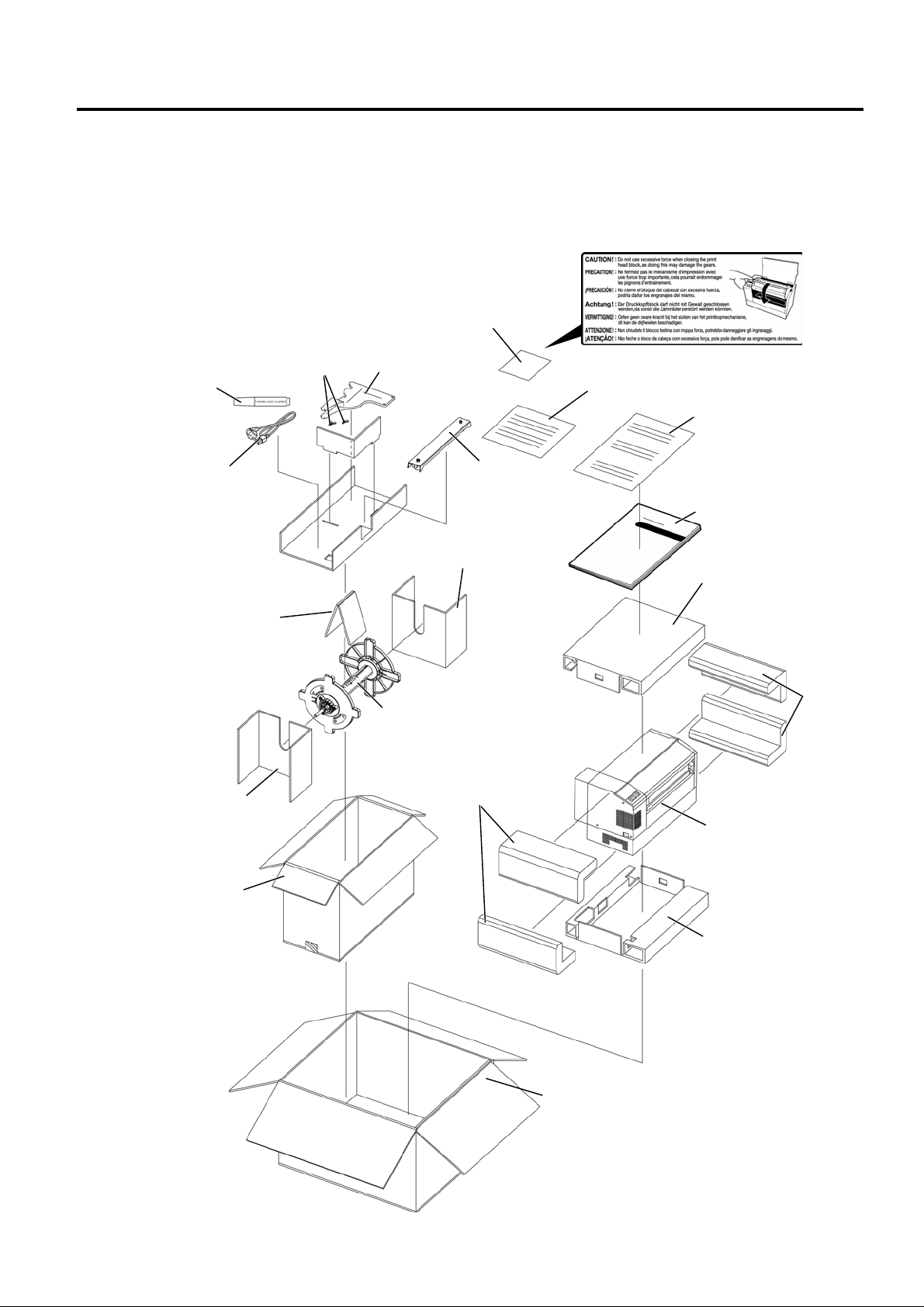
1) Open the carton.
2) Unpack the accessories from the carton.
3) Unpack the pads and the printer from the carton.
Print Head Cleaner
Power Cord
Supply Holder Pad B
Supply Holder Pad A
ccessory Carton
Wing Bolt
Caution Label
(QQ/QP model)
Supply Holder
Frame (L) and (R)
Supply Holder
Base
Supply Holder
Pad
Supply Holder
Unit
Cushion
(Revision Date: Sep. 28, 2007
Caution Label Instruction
(QQ/QP model)
Unpacking Instruction
Owner’s Manual
Top Pad
B-852-R Printer
Bottom Pad
EO18-33018
1.1 Procedure
Cushion
Carton
1- 1
Page 4
1. UNPACKING
(Revision Date: Sep. 28, 2007)
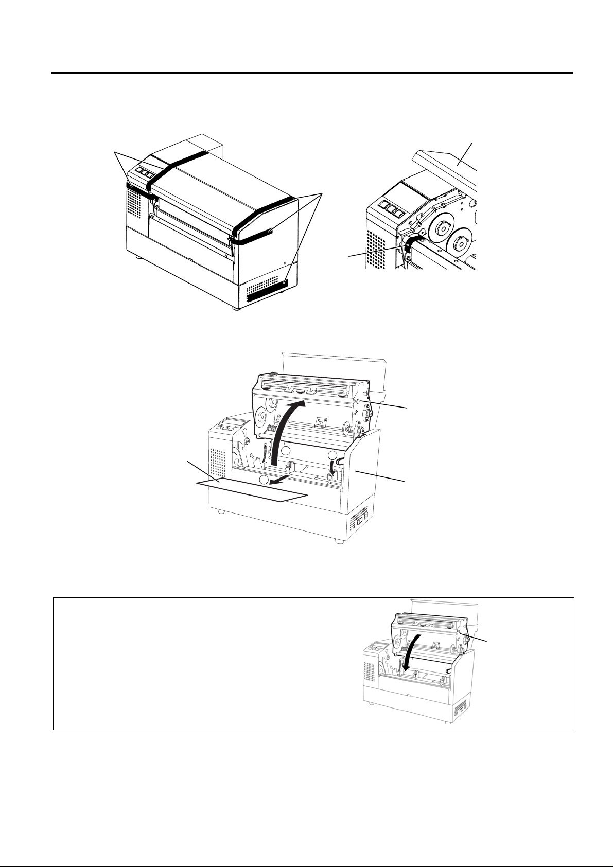
4) Remove the five pieces of tape from the printer.
5) Open the top cover.
6) Remove the one piece of tape.
Tape
Top Cover
Tape
Tape
7) Press down the head block release lever (1) and raise the print head block (2).
8) Remove the print head pad (3).
Print Head Block
Print Head Pad
2
1
3
Head Block Release Lever
9) Place the printer on a level surface.
10) Please attach the supplied Caution Label to an easily visible position on the printer. (QQ/QP
model)
CAUTION!
Do not use excessive force when closing the print head block,
as doing this may damage the gears.
Print Head Block
EO18-33018
1.2 Checks
1.2 Checks
1) Check for damage or scratches on the machine.
2) Confirm that none of the accessories are missing.
NOTE: Keep the carton and pads for later transport.
1- 2
Page 5
2. MAJOR UNIT REPLACEMENT
r
A
EO18-33018
2.1 OPENING AND REMOVING THE COVERS
2. MAJOR UNIT REPLACEMENT
Disconnect the power cord before replacing the parts.
WARNING!
2.1 OPENING AND REMOVING THE COVERS
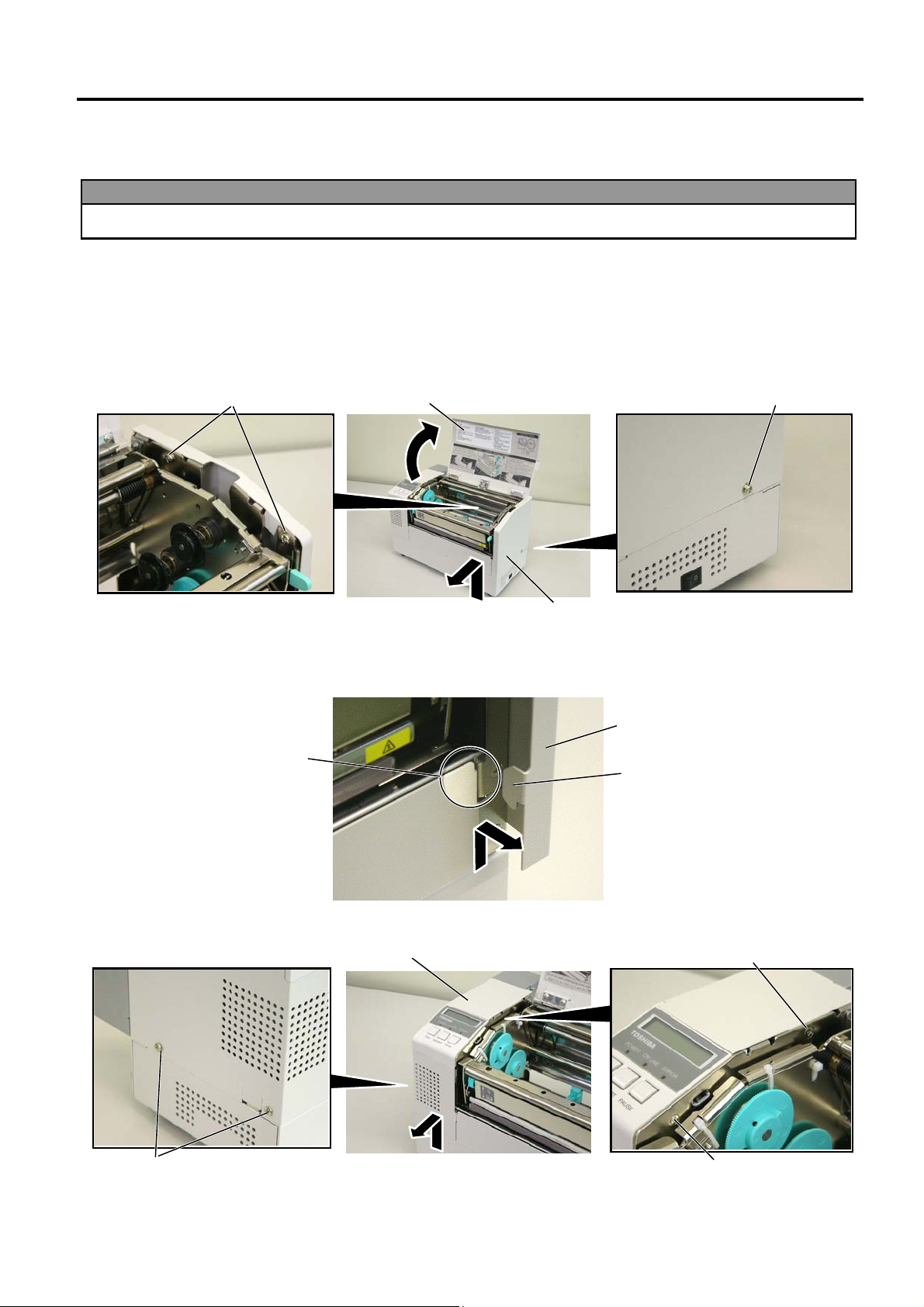
1) Turn the power off.
2) Open the top cover.
3) Remove the three B-4x6 screws to detach the side cover R.
B-4x6 Screw
Top Cove
B-4x6 Screw
Side Cover R
NOTE: After removing the screws, unhook the side cover R from portion A by lifting and moving it toward
the front of the printer.
Side Cover R
Portion
Hook
4) Remove the two B-4x6 screws, PT-3x8 screw and D-4x6 screw to detach the side cover L.
Side Cover L
D-4x6 Screw
B-4x6 Screw
2-1
TT-3x8 Screw
Page 6
2. MAJOR UNIT REPLACEMENT
2.1 OPENING AND REMOVING THE COVERS
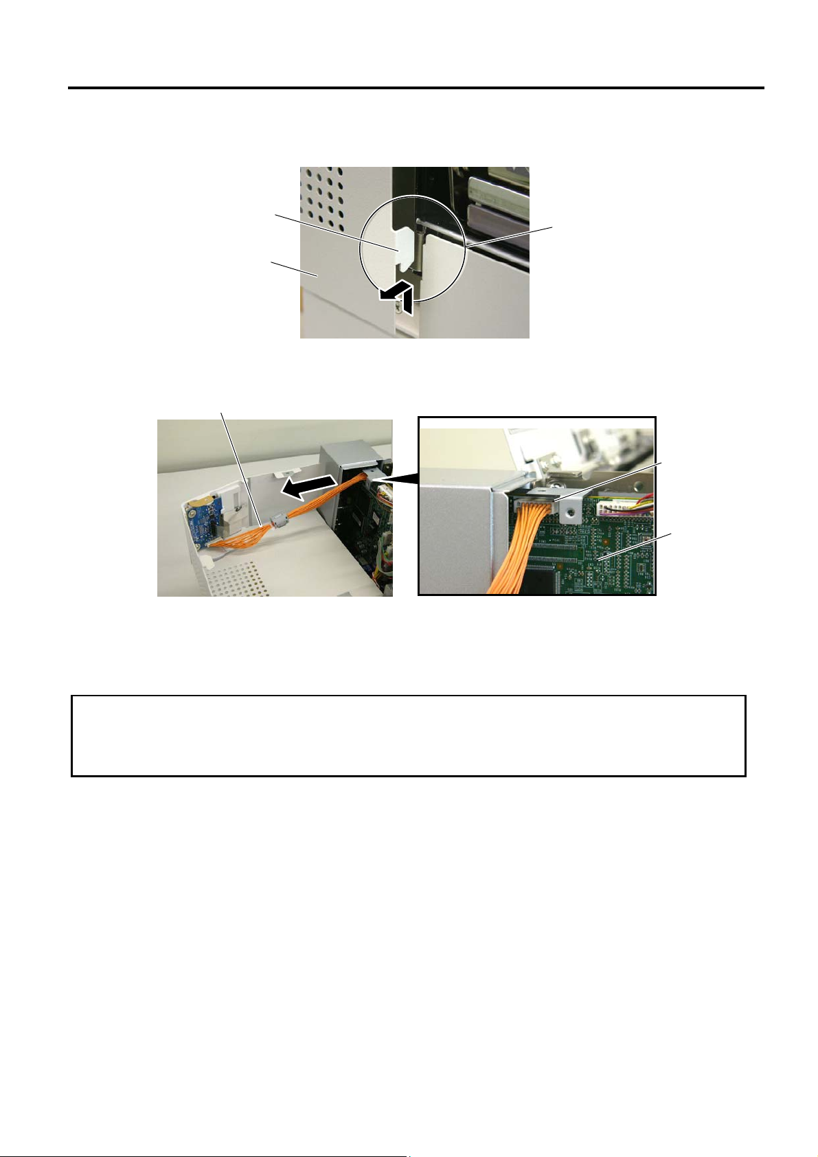
NOTE: After removing the screws, unhook the side cover L from portion B by lifting and moving it toward
the front of the printer.
EO18-33018
Hook
Side Cover L
Portion B
5) Disconnect the operation panel harness from CN13 on the MAIN PC Board.
Operation Panel Harness
CN13
MAIN PC
Board
NOTE: Instructions to open the top cover and to detach the side covers L and R are omitted from each
removal/installation procedure provided below.
2.2 LUBRICATION
CAUTION!
1. Lubrication: During parts replacement
2. Kinds of oil: FLOIL G-488: 1 Kg can. (Parts No. 19454906001)
3. Do not spray the inside of the printer with lubricants. Unsuitable oil can damage the mechanism.
All machines are generally delivered in their best condition. Efforts should be made to keep them that
way. Lack of oil, or the presence of debris or dust, may cause an unexpected failure. To maintain in
optional operating condition, periodically clean the machine and apply the proper kind of oil to each part
in which lubrication is needed.
Although the frequency of lubrication varies according to how often the machine is used, as a minimum
it is necessary to lubricate before any part becomes dry. It is also necessary to wipe off excessive oil
or it will collect dirt.
2-2
Page 7
2. MAJOR UNIT REPLACEMENT
w
2.3 Replacing the MAIN PC Board
2.3 Replacing the MAIN PC Board
1) Prior to replacing the MAIN PC board, print out the parameter settings for future reference.
2) Remove the side cover L from the printer. (Refer to Section 2.1.)
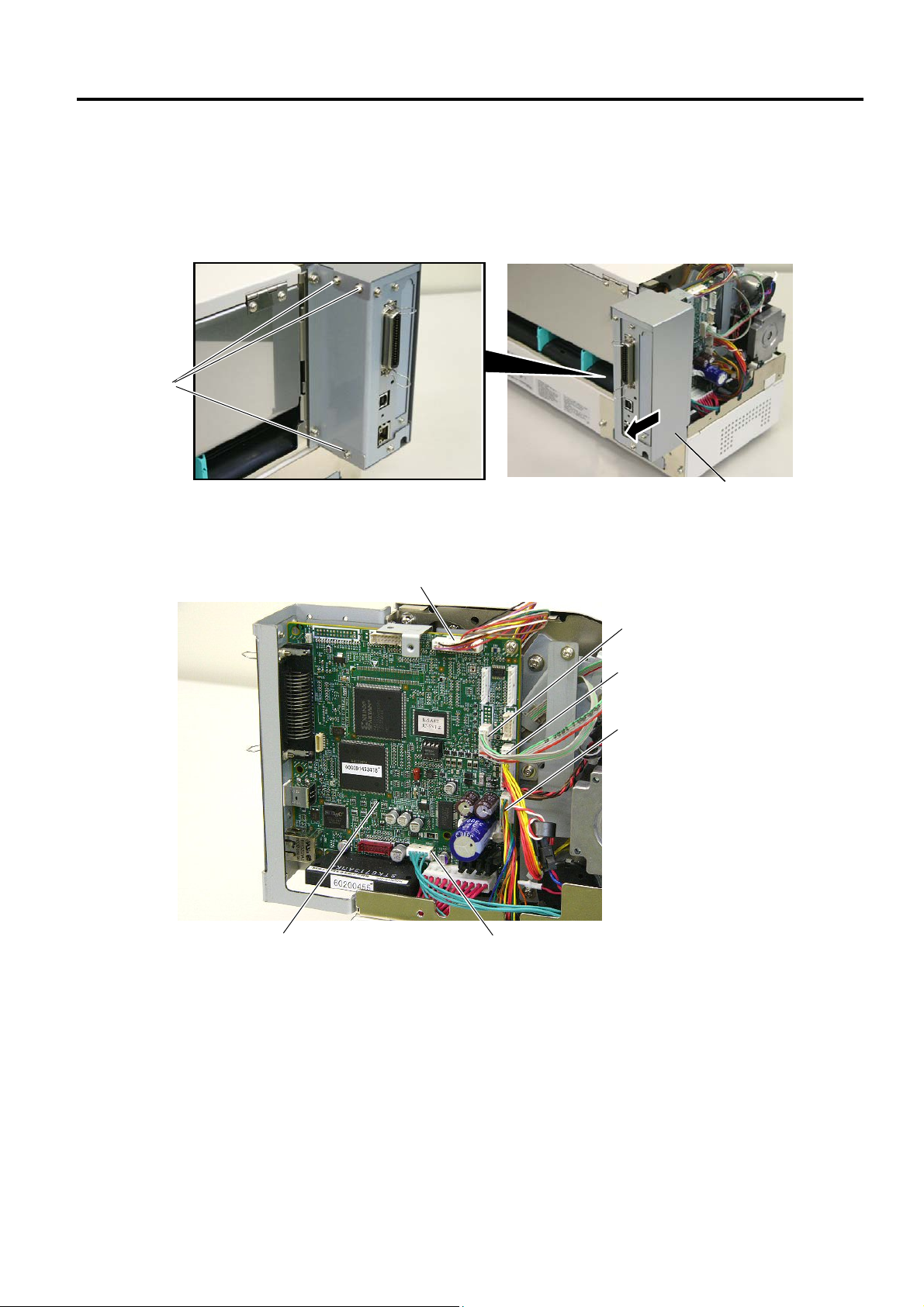
3) Remove the three SMW-3x6 screws to detach the rear frame cover.
SMW-3x6
Scre
EO18-33018
Rear Frame Cover
4) Disconnect the harnesses from CN1, CN2, CN5, CN8, CN9 and CN500 on the MAIN PC board.
CN9 (Print Head Harness, Signal)
CN5 (Media Sensor Harness)
CN2 (Ribbon Motor Harness)
CN1 (Print Head Harness, Power)
MAIN PC Board
CN500 (Stepping Motor Harness)
2-3
Page 8
2. MAJOR UNIT REPLACEMENT
y
y
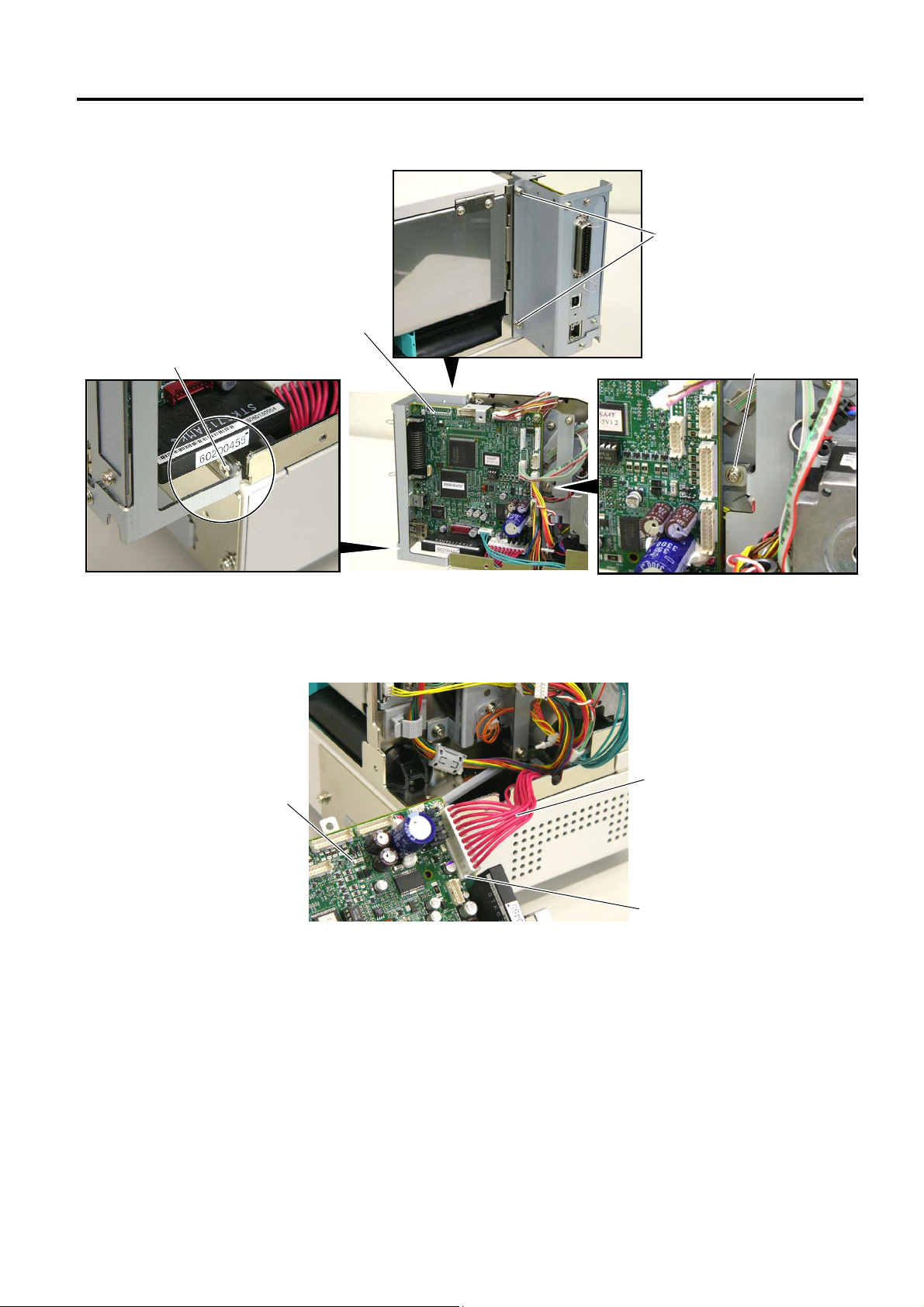
4) Remove the two SMW-4x8 screws, SMW-3x6 screw and B-3x6 screw.
EO18-33018
2.3 Replacing the MAIN PC Board
SMW-4x8 Screw
B-3x6 Screw
MAIN PC Board Ass’
SMW-3x6 Screw
5) Disconnect the power harness from CN8 on the MAIN PC board ass’y, then remove the MAIN PC
board ass’y from the printer.
MAIN PC Board Ass’
Power Harness
CN8
2-4
Page 9
2. MAJOR UNIT REPLACEMENT
2.3 Replacing the MAIN PC Board
EO18-33018
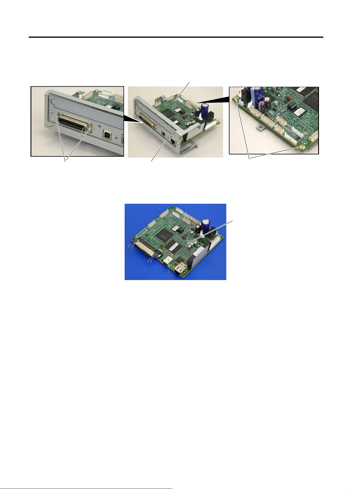
6) Remove the two B-3x6 screws and the two SMW-3x6 screws, then remove the MAIN PC board
from the MAIN PCB support frame.
MAIN PC Board
B-3x6 Screw
MAIN PCB Support Frame
SMW-3x6
7) Replace the MAIN PC board with a new one, and reassemble in the reverse order of removal.
MAIN PC Board
8) After replacing the MAIN PC board, perform the following operations.
(1) Perform a RAM clear.
(2) Restore the printer system setting according to the printout of the parameter settings.
(3) Perform a media sensor adjustment.
(4) Perform a test print to print to confirm that the printer works properly.
2-5
Page 10
2. MAJOR UNIT REPLACEMENT
2.4 Replacing the Panel PC Board
EO18-33018
2.4 Replacing the Panel PC Board
1) Remove the side cover L from the printer. (Refer to Section 2.1.)
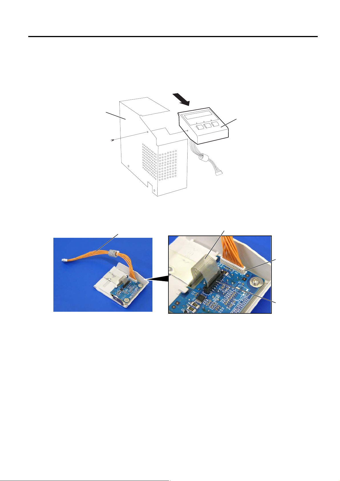
2) Remove the PT-3x8 screw to detach the operation panel ass’y from the side cover L in the direction
indicated by the arrow.
3) Disconnect the operation panel harness from CN2 on the panel PC board.
4) Disconnect the flat cable from CN3 on the panel PC board.
Side Cover L
PT-3x8 Screw
Operation Panel Harness
Operation Panel Ass’y
Flat Cable
CN2
CN3
2-6
Page 11

2. MAJOR UNIT REPLACEMENT
2.4 Replacing the Panel PC Board
5) Remove the two PT-3x6 screws and W-4 washers to detach the panel PC board from the operation
EO18-33018
panel cover.
Operation Panel Cover
Flat Cable
E Plate
Key Switch
Panel PC Board
W-4
W-4
PT-3x6 Screw
6) Replace the panel PC board with a new one, then reassemble in the order removal.
7) Turn the power on, then confirm that the LCD message is displayed properly.
2-7
Page 12

2. MAJOR UNIT REPLACEMENT
r
w
r
2.5 Replacing the Stepping Motor
2.5 Replacing the Stepping Motor
1) Remove the side cover L and MAIN PC board ass’y from the printer.
(Refer to Sections 2.1 and 2.3.)
2) Remove the two SMW-3x6 screws to detach the PCB support plate from the printer.
SMW-3x6 Screw
PCB Support Plate
3) Remove the two SM-4x8 screws to detach the stepping motor from the printer.
EO18-33018
SM-4x8 Screw
Stepping Moto
SM-4x8 Scre
4) Disconnect the harness from the stepping motor.
Stepping Moto
Stepping Motor Harness
5) Replace the stepping motor with a new one, then reassemble in the reverse order of removal.
6) Perform a test print to print to confirm that the printer works properly.
2-8
Page 13

2. MAJOR UNIT REPLACEMENT
r
r
2.5 Replacing the Stepping Motor
EO18-33018
NOTE:
Apply FLOIL to the stepping motor’s pulley and the motor gear when reassembling the stepping motor.
Motor Gea
Pulley
Stepping Moto
2-9
Page 14
2. MAJOR UNIT REPLACEMENT
r
r
A
r
2.6 Replacing the Head Up Sensor, Slit Sensor (Rewind/Feed) and Ribbon Motor (Rewind/Feed)
EO18-33018
2.6 Replacing the Head Up Sensor, Slit Sensor (Rewind/Feed) and Ribbon
Motor (Rewind/Feed)
Prior to replacing the sensors or ribbon motor, perform the following operations.
1) Open the top cover. (Refer to Section 2.1.)
2) Remove the side cover L from the printer. (Refer to Section 2.1.)
3) Press down the head block release lever and raise the print head block.
Print Head Block
Head Block
Release Lever
4) Remove the MAIN PC board ass’y. (Refer to Section 2.3.)
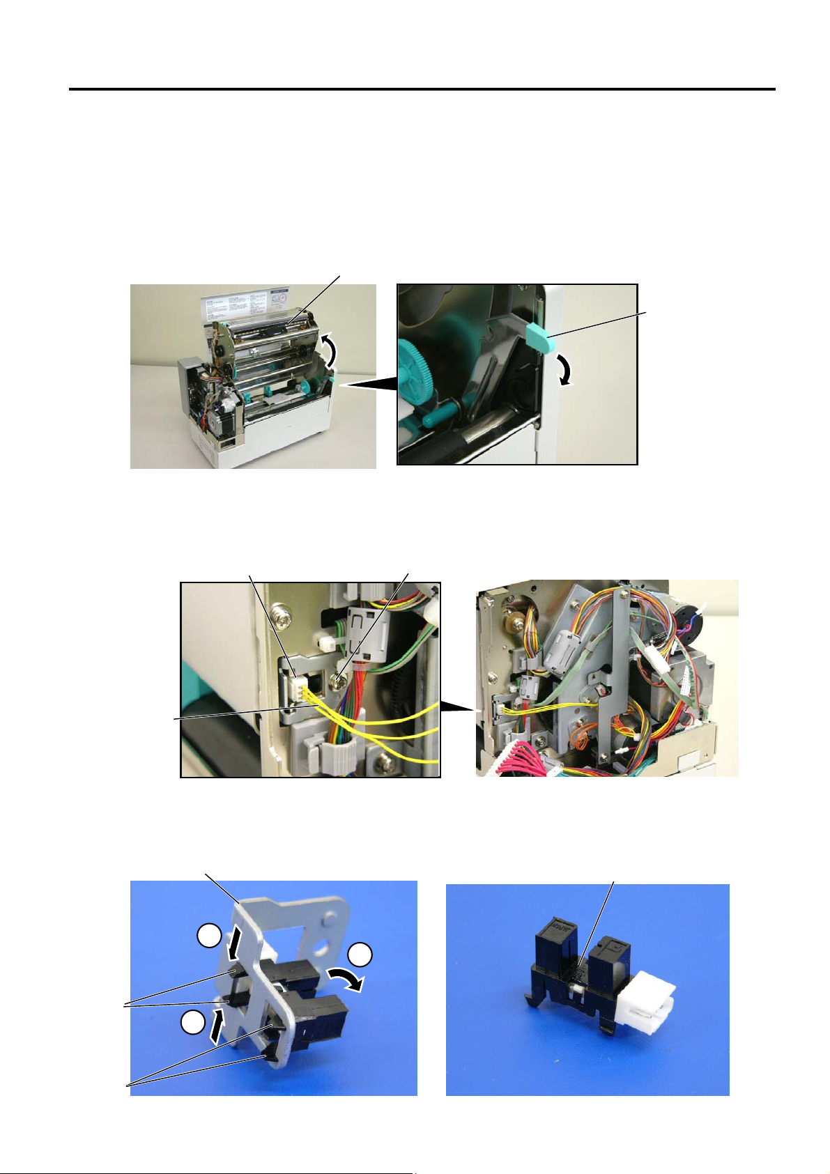
2.6.1 Replacing the Head Up Sensor
1) Remove the sensor harness and the SMW-3x6 screw, then remove the head up sensor from the
printer.
Head Up Senso
Senso
Harness
SMW-3x6 Screw
2) Push and release the hook A, then release the hook B to remove the head up sensor from the
sensor holder.
Sensor Holde
Head Up Sensor
Hook
Hook B
1
2
1
2-10
Page 15

2. MAJOR UNIT REPLACEMENT
2.6 Replacing the Head Up Sensor, Slit Sensor (Rewind/Feed) and Ribbon Motor (Rewind/Feed)
EO18-33018
3) Replace the head up sensor with a new one, then reassemble in the reverse order of removal.
4) Perform a test print to print to confirm that the printer works properly.
NOTE: Be careful not to damage the slit sensor (Rewind/Feed) when replacing it, as this may cause a
malfunction.
2.6.2 Replacing the Slit Sensor (Rewind/Feed)
1) Remove the two SMW-3x6 screws, then remove the PCB support plate from the printer.
PCB Support Plate
SMW-3x6 Screw
2) Remove the media sensor harness from the clamp.
3) Remove the two SMW-4x6 and the two D-3x6 screws, then remove the motor block from the
printer.
SMW-4x6 Screw
Sensor Harness
Motor Block
SMW-4x6 Screw
Cable Clamp
D-3x6 Screw
4) Remove the three SMW-3x6 screws and sensor harnesses, then remove the slit sensor
(rewind/feed) from the motor block.
Slit Sensor (Feed)
Sensor Harness (Red)
Sensor Harness (Brown)
Slit Sensor (Rewind)
Motor Block
Sensor Harness (Orange)
Slit Sensor (Feed)
SMW-3x6 Screw
2-11
Page 16

2. MAJOR UNIT REPLACEMENT
A
r
2.6 Replacing the Head Up Sensor, Slit Sensor (Rewind/Feed) and Ribbon Motor (Rewind/Feed)
EO18-33018
5) Push and release the hook A, then release the hook B to remove the slit sensor from the sensor
holder.
Sensor Holde
Hook
Hook B
1
2
1
Slit Sensor
6) Replace the slit sensor with a new one, then reassemble in the reverse order of removal.
7) Perform a test print to print to confirm that the printer works properly.
NOTES:
1. The colors of the sensor harnesses are different according to the sensor to be connected.
2. Be careful not to damage the slit sensor (Rewind/Feed) when replacing it, as this may cause a
malfunction.
2.6.3 Replacing the Ribbon Motor (Rewind/Feed)
1) Prior to replacing the ribbon motor, print out the maintenance counter for future reference.
2) Remove the SMW-2.6x6 screws to remove the ribbon motor (rewind/feed).
SMW-2.6x6 Screw
Ribbon Motor (Rewind)
Ribbon Motor (Feed)
SMW-2.6x6 Screw
3) Replace the ribbon motor with a new one, then reassemble in the reverse order of removal.
2-12
Page 17

2. MAJOR UNIT REPLACEMENT
r
r
2.6 Replacing the Head Up Sensor, Slit Sensor (Rewind/Feed) and Ribbon Motor (Rewind/Feed)
EO18-33018
NOTES:
1. After replacing the ribbon motor, refer to Section System Mode Manual to perform a Maintenance
Counter clear.
2. Secure the ribbon motors while inserting a 0.1 mm-thick paper (or folded backing paper) between
the ribbon motor pulley and the idler gear to adjust the backlash. After the ribbon motors is
secured, remove the paper.
Ribbon Motor Pulley (Rewind)
Idler Gea
Ribbon Moto
Pulley (Feed)
Idler Gear
4) Perform a test print to print to confirm that the printer works properly.
2-13
Page 18

2. MAJOR UNIT REPLACEMENT
2.7 Replacing the Platen
EO18-33018
2.7 Replacing the Platen
1) Prior to replacing the platen, print out the maintenance counter for future reference.
2) Open the top cover, and raise the print head block by pressing down the head block release lever.
Top Cover
Print Head
Head Block
2
1
Release Lever
3) While pulling the top part of the platen holders L and R to the ce nter of the printer, move them to the front
of the printer to remove.
4) Push the platen and strip plate to the left side and then, move them to the front side to remove.
Platen Holder L
Platen
Platen Holder R
Shaft Holder
Strip Plate
5) Remove the shaft holder from the platen.
NOTE: Be careful not to damage the shaft holder when removing it.
Platen
Shaft Holder
2-14
Page 19

2. MAJOR UNIT REPLACEMENT
2.7 Replacing the Platen
EO18-33018
6) Replace the platen with a new one, then reassemble in the reverse order of removal.
NOTE: When reassembling, confirm the orientation of the shaft holder. (See the picture below.)
Platen
Shaft Holder
7) Perform a test print to confirm that the printer works properly.
2-15
Page 20

2. MAJOR UNIT REPLACEMENT
p
)
A
2.8 REPLACING THE MEDIA SENSOR
EO18-33018
2.8 REPLACING THE MEDIA SENSOR
2.8.1 Feed Gap Sensor (TR) and Black Mark Sensor (Upper Side)
1) Open the top cover and raise the print head block.
2) Pull up the two tabs of the sensor case cap to remove it from the sensor block.
3) Remove the feed gap sensor (TR) and black mark sensor (upper side) from the sensor case.
Disconnect the media sensor harness.
Tab
Sensor Case Cap
Media Sensor Harness
Black Mark Sensor
(Upper Side)
Sensor Case
Feed Ga
Sensor (TR
Hook
Front side of
the printer
4) Replace the sensors with new ones, then reassemble in the reverse order of removal.
NOTES: 1. When reassembling the sensor case cap, fit the hooks of the sensor case into portion A of
the sensor case cap.
2. When reassemblin g the sensors, align the pins on the sensor case with the holes of the
sensors.
3. Connect the harness including the green wire to the black mark sensor (Upper side).
4. Pass the media sensor harness between the harness guides.
Black Mark Sensor (Upper side)
(Number of pins: 3)
Green
Sensor Case
Pin
Feed Gap Sensor (TR)
Sensor Guide
Media Sensor Harness
Front side of the printer
5. Since connectors of the sensors are small, be careful not to break their pins.
2-16
Page 21

2. MAJOR UNIT REPLACEMENT
A
2.8.2 Feed Gap Sensor (LED) and Black Mark Sensor (Low er Side)
2.8 REPLACING THE MEDIA SENSOR
EO18-33018
1) Remove the platen holder R, platen holder L, platen, and strip plate from the printer
2) Remove the SMW-4x8 screw to detach the front cover from the printer.
3) Unhook the two springs.
4) Remove the two SMW-3x6 screws to detach the sensor block from the pritner.
A
SMW-3x6 Screw
Sensor Block
Spring
SMW-4x8 Screw
To CN15 on the
CPU PC board
ass’y
A
Spring
Front Cover
5) Turn over the sensor block.
6) Pull up the two tabs of the sensor case cap to remove it from the sensor case.
7) Remove the feed gap sensor (LED) and black mark sensor (lower side) from the sensor case,
and disconnect the media sensor harness from each sensor.
Tab
Sensor Case Cap
Black Mark Sensor
(Lower Side)
Front side of
the printer
Media Sensor Harness
Sensor Case
Feed Gap Sensor (LED)
Hook
8) Replace the sensor with a new one, then reassemble in the reverse order of removal.
2-17
Page 22

2. MAJOR UNIT REPLACEMENT
2.8 REPLACING THE MEDIA SENSOR
EO18-33018
NOTES: 1. When reassembling the sensor case cap, fit the hooks of the sensor case into
portion A of the sensor case cap.
2. When reassembling the sensors, align the pins on the sensor case with the holes of
the sensors.
3. Connect the harness including the green wire to the black mark sensor (lower side).
4. Pass the media sensor harness between the harness guides.
Front side of
the printer
Black Mark Sensor
(Lower side)
Green
Sensor Case
Pin
Feed Gap Sensor (LED)
(Number of pins: 2)
Sensor Guide
Media Sensor Harness
5. Since connectors of the sensors are small, be careful not to break their pins.
2-18
Page 23

2. MAJOR UNIT REPLACEMENT
2.9 REPLACING THE PRINT HEAD
EO18-33018
2.9 REPLACING THE PRINT HEAD
CAUTION:
1. Never touch the print head element when handling the print head.
2. Never touch the connector pins to avoid a breakdown of the print head by static electricity.
3. Never remove the screws which secure the print head to the bracket. Doing so may cause
improper print quality.
4. Never disassemble the head block frame. Doing so may cause a print failure, such as ribbon
wrinkle, blurred print, etc.
NEVER remove these screws.
Print Head
Head Block Frame
Bracket
1) Open the top cover and raise the print head block.
2) Push the print head ass’y to the right side, lift it in the direction of the arrow, and release it from the
print head fixing pin.
3) Disconnect the print head harnesses from the three connectors of the print head.
Hole
Print Head Ass’y
Print Head Harness
Spring
Print Head Fixing Pin
Print Head Harness
5) Replace the print head with a new one, then reassemble in the reverse order of removal.
NOTES: 1. Install the print head in position by fitting its holes into the spring and print head fixing
pin.
2. After replacing the print head, refer to Section 6.8 to perform a Maintenance Counter
Clear.
2-19
Page 24

2. MAJOR UNIT REPLACEMENT
w
2.10 Replacing the PS Unit and Reactor
EO18-33018
(Revision Date: May 21, 2007)
2.10 Replacing the PS Unit and Reactor
1. Hazardous electrical parts. Before disassembling the unit, unplug the power cord from the mains.
2. As the printer block and PS unit are heavy, be careful not to pinch your fingers or drop it on your
feet.
3. The PS unit should be replaced as a unit. Never disassemble the PS unit. Doing so may cause a
fire or machine failure.
WARNING!
NOTE: The reactor is installed in the B-852-TS22-QP-R and B-852-TS22-CN models.
1) Remove the side covers L, side cover R and MAIN PC Board from the printer.
2) Raise the print head block.
3) Remove the platen.
4) Remove the four SMW-4x8 screws to remove the power supply block from the printer block.
SMW-4x8 Screw
SMW-4x8 Scre
SMW-4x8 Screw
SMW-4x8 Screw
Printer Block
Power Supply Block
2-20
Page 25

2. MAJOR UNIT REPLACEMENT
t
5) Disconnect the PSU harness from CN4 on the PS unit.
EO18-33018
(Revision Date: May 21, 2007)
2.10 Replacing the PS Unit and Reactor
PS Uni
PSU Harness
CN4
6) Disconnect the harnesses from CN1 on the PS unit. For the QP and CN models, disconnect the
harness from CN2, too.
7) Remove the two SMW-4x8 screws to detach the PS unit from the PSU base.
8) Remove the SMW-4x8 screws to detach the reactor from the PSU base. (QP and CN models)
SMW-4x8 Screw
CN2
B
Inlet Harness
A
CN1
SMW-4x8 Screw
Reactor (QP and CN models)
PS Unit
Reactor Harness
B
PSU Base
A
2-21
Page 26

2. MAJOR UNIT REPLACEMENT
t
2.10 Replacing the PS Unit and Reactor
EO18-33018
9) Replace the PS unit or reactor with a new one, then reassemble in the reverse order of removal.
Pass the reactor harness and inlet harness through the cut in the PS unit frame. Care must be taken
not to pinch the harnesses in the frame. Failure to do this may break the harnesses causing a fire or
electric shock.
WARNING!
Inlet
PSU Base
Reactor Harness
Inlet Harness
Cu
PS Unit
2-22
Page 27

3. PERIODIC MAINTENANCE PROCEDURE
3. PERIODIC MAINTENANCE PROCEDURE
3. PERIODIC MAINTENANCE PROCEDURE
EO18-33018
1. Be sure to turn the power off before cleaning the cutter unit.
2. As the cutter blade is sharp, care should be taken not to injure yourself when cleaning.
WARNING!
All machines are generally delivered in their best condition. To maintain optimal operating condition
and help gain maximum performance and life of machines, we would recommend you to conduct
periodic maintenance. Doing this is also effective in preventing unexpected troubles and avoiding
wasteful system down time, by which more benefit is produced to your customers and greater reliance
is placed on the product quality.
Please refer to the following general maintenance procedure and perform periodic servicing.
NOTE: Before starting the periodic maintenance, be sure to read carefully and understand the Service
Manuals, especially warnings, cautions and adjustment.
1. Ask an operator or a manager about any machine trouble.
2. Check the run distance on the maintenance counter.
3. Unplug the power cord, and then open the top cover and the head block.
Head
Block
Top
Cover
Power Cord
4. Clean the inside of the printer.
1) The entire inside of the printer should be cleaned.
2) Wipe the platen with a cloth moistened with alcohol.
Platen
3-1
Page 28

3. PERIODIC MAINTENANCE PROCEDURE EO18-33018
Element
Media Sensor
3. PERIODIC MAINTENANCE PROCEDURE
3) Clean the print head elements with the TOSHIBA TEC-approved print head cleaner.
(Please instruct your customers to clean them daily.)
Print Head Cleaner
Print Head
Print Head
4) Remove any paper dust and glue of the label. Wipe off moving range of the media sensor.
Media Path
Moving range of the
3-2
Page 29

3. PERIODIC MAINTENANCE PROCEDURE EO18-33018
3. PERIODIC MAINTENANCE PROCEDURE
5. Apply FLOIL G-488 to the cutter unit using a soft cloth.
6. Clean the Cutter Blade with a cotton swab moistened with absolute ethyl alcohol.
Cutter Blade
Cutter Unit
7. Confirm that the problem occurs as reported, and then take correct ive action.
8. Replace the following parts periodically, if necessar y. The following table shows approximate
product life for each part.
No.
Part Name Part No.
Standard interval of
replacement
1 Cutt er unit (Option) G0-00415000 1,000,000 cuts
2 Platen FMCC0054701 50 km
NOTES: 1. The above values of the cutter life are obtained on condition that the periodically
maintained cutter is used with TOSHIBA TEC-approved supplies by the proper
method described in the manuals.
2. The above values differ depending on t he t hickness and subst ances of the media to
be used. When using t he cut ter to cut the labels, be sure to cut the backing paper.
Failure to do this may cause the glue to stick to the cutter and shorten the cutter life.
8. Confirm each part adjustment . Make any necessary adjustments.
9. Conduct the following tests and make sure that there is no problem.
1) Print test with TOSHIBA TEC-approved media and ribbon. (Print tone, print head position,
etc.)
2) Paper skew
3) Print star t position adjustment (Horizontal: media position, vertical: sensor
adjustment/adjustment by issuing com m ands. )
4) Communication test
5) Abnormal noise
6) Confirm that there are not any other error s .
10. Close the top cover.
3-3
Page 30
3. PERIODIC MAINTENANCE PROCEDURE
3. PERIODIC MAINTENANCE PROCEDURE
11. Clean the outside of the printer.
12. Fill out a report form. Hand it to the manager and obtain a signature.
EO18-33018
3-4
Page 31

4. TROUBLESHOOTING
EO18-33018
4. TROUBLESHOOTING
Problems Cause Solution
Power does not
turn ON.
LED or LCD does
not light.
Poor printing 1. Poor media quality.
Printer does not
print.
Dot missing 1. Broken print head element
Blurred print 1. Poor media quality.
Ribbon wrinkle 1. Poor ribbon quality.
1. Input voltage to the printer is not
within the rated voltage.
2. Output voltage from the printer is not
within the rated voltage.
3.
No voltage to the MAIN PC board.
4.
Failure of MAIN PC board.
1. Failure of the panel PC board or
operation panel
2.
Failure of the operation panel
harness
3.
Failure of the MAIN PC board
2. Dirty print head
3.
The print head block is not set
completely.
1. Print head failure
2. Connection of the print head
connector is incomplete, a bad
contact, or broken elements.
3. Failure in rewinding/feeding of the
ribbon.
4. Failure of the MAIN PC board.
5. Failure of the software
6.
Failure of the printer cable.
2. Broken print head cable wires
3.
Failure of the MAIN PC board
2.
Dust is on the media.
2.
Ribbon is not rewound or fed
smoothly.
4. TROUBLESHOOTING
Replace the power cable or power
inlet.
Replace the PS unit.
Check if the power harness is
connected to CN8 on the MAIN PC
board correctly.
Replace the power harness or Power
Supply Unit.
Replace the MAIN PC board.
Replace the panel PC board or
operation panel.
Replace the operation panel harness.
Replace the MAIN PC board.
Use the media approved by
TOSHIBA TEC.
Clean the print head.
Close the print head block
completely.
Replace the print head.
Connect the harness completely, or
replace the harness.
Replace the ribbon rewind motor,
ribbon feed motor or MAIN PC board.
Replace the MAIN PC board.
Check the program.
Replace the printer cable.
Replace the print head.
Replace the print head harness.
Replace the MAIN PC board.
Use only TOSHIBA TEC-approved
media.
Clean the print head and remove any
dust from the media.
Use only TOSHIBA TEC-approved
ribbon.
Replace the ribbon rewind motor or
ribbon feed motor.
4- 1
Page 32

4. TROUBLESHOOTING
EO18-33018
Problems Cause Solution
Media feed failure 1. Media is not set properly.
2.
Poor media quality
3.
Improper adjustment of the feed gap
sensor or black mark sensor.
4.
Threshold is improper.
5.
Failure of the feed gap sensor or
black mark sensor
6.
The cutter mechanism is not
installed properly.
7.
Failure of the stepping motor.
Communication
error
1. Failure of the communication cable
2.
Failure of the RS-232C connector
3.
Failure of the communication
connector
4.
Failure of the PC or application
software
5.
Failure of the SIO PC board.
(Option)
4. TROUBLESHOOTING
Set the media properly.
Use the media approved by
TOSHIBA TEC.
Re-adjust the sensor.
Set the threshold correctly.
Replace the feed gap sensor or black
mark sensor.
Install the cutter module properly.
Replace the stepping motor or MAIN
PC board.
Replace the cable.
Replace the connector
Replace the connector.
Modify the program.
Replace the SIO PC Board.
4- 2
 Loading...