

Page 1

TEC Label/Tag Printer
B-852-TS12-QQ
Owner's Manual
Page 2
This equipment has been tested and found to comply with the limits for a Class A digital device,
pursuant to Part 15 of the FCC Rules. These limits are designed to provide reasonable protection
against harmful interference when the equipment is operated in a commercial environment. This
equipment generates, uses, and can radiate radio frequency energy and, if not installed and used in
accordance with the instruction manual, may cause harmful interference to radio communications.
Operations of this equipment in a residential area is likely to cause harmful interference in which
case the user will be required to correct the interference at his own expense.
(for USA only)
Changes or modifications not expressly approved by manufacturer for compliance could void the
user’s authority to operate the equipment.
“This Class A digital apparatus meets all requirements of the Canadian Interference-Causing
Equipment Regulations.”
“Cet appareil numérique de la classe A respecte toutes les exigences du Règlement sur le matériel
brouilleur du Canada.”
(for CANADA only)
HP-PCL5 is a registered trademark of Hewlett Packard Corporation.
Centronics is a registered trademark of Centronics Data Computer Corp.
Microsoft is a registered trademark of Microsoft Corporation.
Windows is a trademark of Microsoft Corporation.
As an ENERGY STAR® Partner, TOSHIBA TEC has determined that this
E
product meets the
NERGY STAR® guidelines for energy efficiency.
-- Outline of the International ENERGY STAR® Office Equipment Program --
The International
E
NERGY STAR® Office Equipment Program is an international program that
promotes energy saving through the penetration of energy efficient computers and other office
equipment. The program backs the development and dissemination of products with functions
that effectively reduce energy consumption. It is an open system in which business proprietors
can participate voluntarily. The targeted products are office equipment such as computers,
monitors, printers, facsimiles, copiers, scanners, and multifunction devices. Their standards and
logos are uniform among participating nations.
E
NERGY STAR is a U.S. registered mark.
Copyright © 2002
by TOSHIBA TEC CORPORATION
All Rights Reserved
570 Ohito, Ohito-cho, Tagata-gun, Shizuoka-ken, JAPAN
Page 3
Safety Summary
6DIHW\6XPPDU\
Personal safety in handling or maintaining the equipment is extremely important. Warnings and Cautions
necessary for safe handling are included in this manual. All warnings and cautions contained in this manual
should be read and understood before handling or maintaining the equipment.
Do not attempt to effect repairs or modifications to this equipment. If a fault occurs that cannot be rectified
using the procedures described in this manual, turn off the power, unplug the machine, then contact your
authorized TOSHIBA TEC representative for assistance.
0HDQLQJVRI(DFK6\PERO
This symbol indicates warning items (including cautions).
Specific warning contents are drawn inside the symbol.
(The symbol on the left indicates a general caution.)
This symbol indicates prohibited actions (prohibited items).
Specific prohibited contents are drawn inside or near the
(The symbol on the left indicates “no disassembling”.)
This symbol indicates actions which must be performed.
Specific instructions are drawn inside or near the ● symbol.
(The symbol on the left indicates “disconnect the power cord plug from the outlet”.)
symbol.
EO1-33029
$Q\RWKHUWKDQWKH
VSHFLILHG$&YROWDJH
LVSURKLELWHG
3URKLELWHG
3URKLELWHG
'LVFRQQHFW
WKHSOXJ
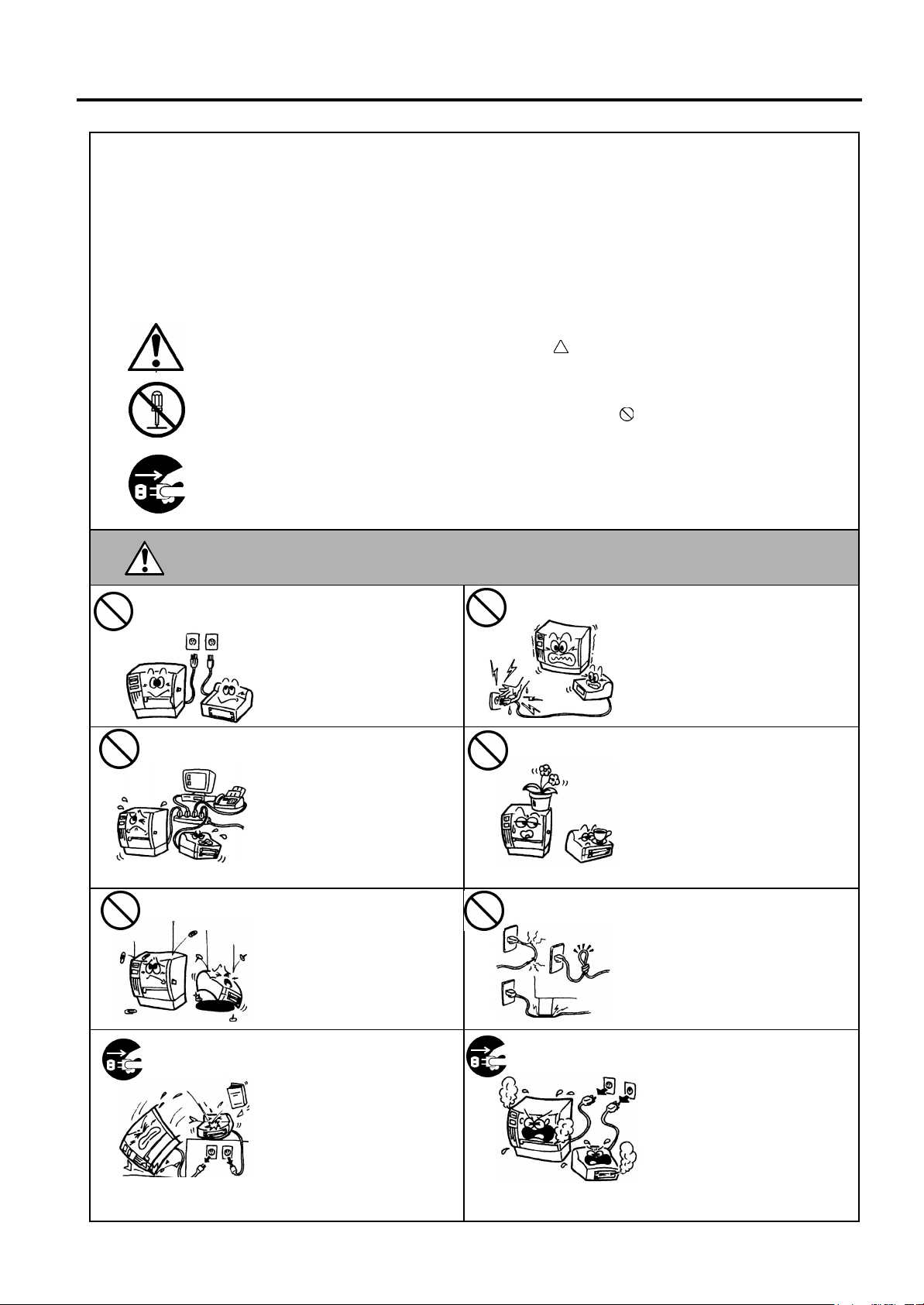
:$51,1*
Do not use voltages other than
the voltage (AC) specified on
the rating plate, as this may
cause
If the machines share the same
outlet with any other electrical
appliances which consume
large amounts of power, the
voltage will fluctuate widely
each time these appliances
operate. Be sure to provide an
exclusive outlet for the
machine as this may cause the
machines to
Do not insert or drop metal,
flammable or other foreign
objects into the machines
through the ventilation slits, as
this may cause
shock
If the machines are dropped or
their cabinets damaged, first
turn off the power switches and
disconnect the power cord
plugs from the outlet, and then
contact your authorized
TOSHIBA TEC representative
for assistance. Continued use
of the machine in that condition
may cause
shock
fire
.
.
or
fire
This indicates that there is the risk of death or serious injury if the
machines are improperly handled contrary to this indication.
Do not plug in or unplug the power
cord plug with wet hands as this
may cause
Do not place metal objects or
water-filled containers such as
flower vases, flower pots or mugs,
etc. on top of the machines. If
metal objects or spilled liquid enter
the machines, this may cause
or
electric shock
Do not scratch, damage or modify
the power cords. Also, do not
place heavy objects on, pull on, or
excessively bend the cords, as this
may cause
electric shock
.
or
fire
electric shock
electric shock
malfunction
or
fire
electric
3URKLELWHG
.
3URKLELWHG
.
3URKLELWHG
Continued use of the machines in
an abnormal condition such as
when the machines are producing
smoke or strange smells may cause
or
fire
electric shock
cases, immediately turn off the
power switches and disconnect the
power cord plugs from the outlet.
Then, contact your authorized
TOSHIBA TEC representative for
assistance.
. In these
or
electric
'LVFRQQHFW
WKHSOXJ
.
fire
.
( )
i
Page 4
Safety Summary
EO1-33029
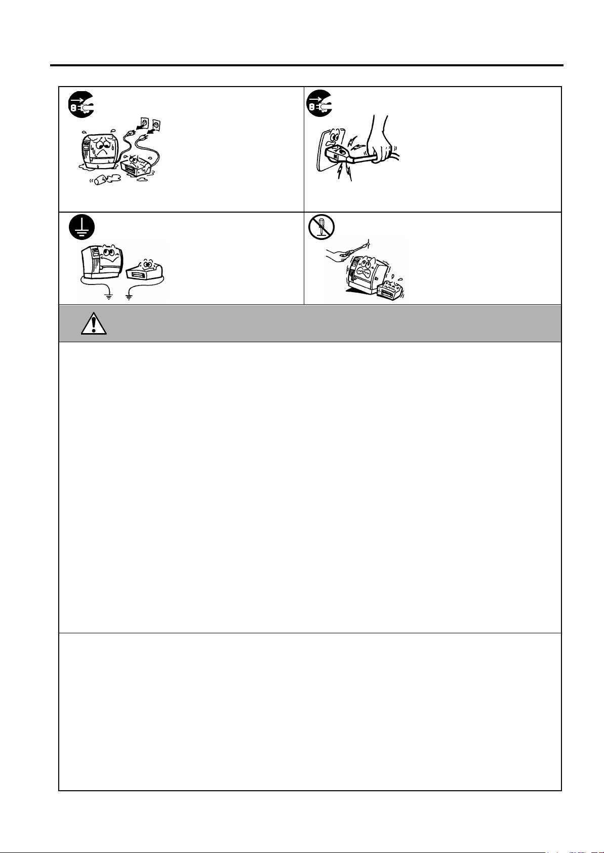
'LVFRQQHFW
WKHSOXJ
&RQQHFWD
JURXQGLQJZLUH
If foreign objects (metal
fragments, water, liquids) enter
the machines, first turn off the
power switches and disconnect
the power cord plugs from the
outlet, and then contact your
authorized TOSHIBA TEC
representative for assistance.
Continued use of the machine in
that condition may cause
electric shock
Ensure that the equipment is
properly grounded. Extension
cables should also be grounded.
or
Fire
occur on improperly grounded
equipment.
.
electric shock
fire
could
or
'LVFRQQHFW
WKHSOXJ
1R
GLVDVVHPEOLQJ
When unplugging the power cords,
be sure to hold and pull on the plug
portion. Pulling on the cord portion
may cut or expose the internal wires
and cause
Do not remove covers, repair or
modify the machine by yourself.
You may be
voltage, very hot parts or sharp
edges inside the machine.
fire
injured
or
electric shock
&$87,21
This indicates that there is the risk of personal
the machines are improperly handled contrary to this indication.
Injury
or
damage
to objects if
3UHFDXWLRQV
The following precautions will help to ensure that this machine will continue to function correctly.
Try to avoid locations that have the following adverse conditions:
●
* Temperatures out of the specification * Direct sunlight * High humidity
* Shared power source * Excessive vibration * Dust/Gas
The cover should be cleaned by wiping with a dry cloth or a cloth slightly dampened with a mild
●
detergent solution. NEVER USE THINNER OR ANY OTHER VOLATILE SOLVENT on the plastic
covers.
USE ONLY TOSHIBA TEC SPECIFIED paper and ribbons.
●
DO NOT STORE the paper or ribbons where they might be exposed to direct sunlight, high
●
temperatures, high humidity, dust, or gas.
Ensure the printer is operated on a level surface.
●
Any data stored in the memory of the printer could be lost during a printer fault.
●
Try to avoid using this equipment on the same power supply as high voltage equipment or equipment
●
likely to cause mains interference.
Unplug the machine whenever you are working inside it or cleaning it.
●
Keep your work environment static free.
●
Do not place heavy objects on top of the machines, as these items may become unbalanced and fall
●
causing injury.
Do not block the ventilation slits of the machines, as this will cause heat to build up inside the
●
machines and may cause fire.
Do not lean against the machine. It may fall on you and could cause injury.
●
Care must be taken not to injure yourself with the printer paper cutter.
●
Unplug the machine when it is not used for a long period of time.
●
.
by high
5HTXHVW5HJDUGLQJ0DLQWHQDQFH
Utilize our maintenance services.
●
After purchasing the machine, contact
ii
our authorized TOSHIBA TEC representative for assistance
once a year to have the inside of the machine cleaned. Otherwise, dust will build up inside the
machines and may cause a fire or a malfunction. Cleaning is particularly effective before humid rainy
seasons.
Our preventive maintenance service performs the periodic checks and other work required to maintain
●
the quality and performance of the machines, preventing accidents beforehand.
For details, please consult your authorized TOSHIBA TEC representative for assistance.
Using insecticides and other chemicals
●
Do not expose the machines to insecticides or other volatile solvents. This will cause the cabinet or
other parts to deteriorate or cause the paint to peel.
( )
ii
Page 5

EO1-33029
TABLE OF CONTENTS
Page
1. PRODUCT OVERVIEW............................................................................................................1-1
1.1 Introduction...................................................................................................................... 1-1
1.2 Features........................................................................................................................... 1-1
1.3 Unpacking........................................................................................................................ 1-1
1.4 Accessories ..................................................................................................................... 1-2
1.5 Appearance...................................................................................................................... 1-3
1.5.1 Dimensions...................................................................................................................1-3
1.5.2 Front View.....................................................................................................................1-3
1.5.3 Rear View.....................................................................................................................1-3
1.5.4 Operation Panel............................................................................................................1-4
1.5.5 Interior...........................................................................................................................1-4
2. PRINTER SETUP ..................................................................................................................... 2-1
2.1 Precautions...................................................................................................................... 2-1
2.2 Procedure before Operation ............................................................................................ 2-2
2.3 Assembling the Accessories............................................................................................ 2-3
2.3.1 Assembling the Supply Holder Frame...........................................................................2-3
2.4 Connecting the Cables to Your Printer ............................................................................ 2-4
2.5 Connecting the Power Cord............................................................................................. 2-5
2.6 Turning the Printer ON/OFF............................................................................................. 2-6
2.6.1 Turning ON the Printer..................................................................................................2-6
2.6.2 Turning OFF the Printer................................................................................................2-6
2.7 Loading the Media........................................................................................................... 2-7
2.7.1 Installing the Media onto the Supply Holder Unit ..........................................................2-7
2.7.2 Installing the Supply Holder onto the Supply Holder Frame..........................................2-9
2.7.3 Loading Media into the Printer......................................................................................2-9
2.8 Setting Sensor Positions................................................................................................ 2-12
2.8.1 Setting the Feed Gap Sensor .....................................................................................2-12
2.8.2 Setting the Black Mark Sensor....................................................................................2-12
2.9 Loading the Ribbon........................................................................................................ 2-13
2.10 Inserting the Optional PCMCIA Cards........................................................................... 2-14
2.11 Test Print........................................................................................................................ 2-15
3. PRINTER OPERATION............................................................................................................ 3-1
3.1 Overview.......................................................................................................................... 3-1
3.2 Operating Modes ............................................................................................................. 3-1
3.3 Installing the Printer Drivers............................................................................................. 3-3
3.3.1 System Requirements...................................................................................................3-3
3.3.2 Driver Download ...........................................................................................................3-3
3.3.3 Driver Installation..........................................................................................................3-5
3.3.4 Add Printer....................................................................................................................3-7
3.4 Using the B-852 Printer Properties Menus ...................................................................... 3-9
3.4.1 Summary of Properties...............................................................................................3-10
3.4.2 General Properties Tab...............................................................................................3-11
3.4.3 Details Tab..................................................................................................................3-12
3.4.4 Regional Settings Tab.................................................................................................3-15
3.4.5 Page Setup Tab..........................................................................................................3-17
3.4.6 Graphic Tab................................................................................................................3-20
3.4.7 Bar Font Tab...............................................................................................................3-21
3.4.8 Stock Tab....................................................................................................................3-24
3.4.9 Options Tab................................................................................................................3-28
3.4.10 Testing Tab................................................................................................................3-29
3.4.11 About Tab..................................................................................................................3-32
3.3.5 Uninstalling the TEC B-852 Printer Driver.....................................................................3-8
Page 6

EO1-33029
Please refer to your local Authorized Service representative with regard to any queries you may have in
4. ON LINE MODE......................................................................................................................4-1
4.1 Operation Panel..............................................................................................................4-1
4.2 Operation........................................................................................................................4-2
4.3 Reset..............................................................................................................................4-2
4.4 Dump Mode....................................................................................................................4-2
5. MAINTENANCE......................................................................................................................5-1
5.1 Cleaning.........................................................................................................................5-1
5.1.1 Print Head/Platen/Sensors..............................................................................................5-1
5.1.2 Covers and Panels..........................................................................................................5-2
5.1.3 Optional Cutter Module...................................................................................................5-2
5.2 Care/Handling of the Media and Ribbon.........................................................................5-2
6. TROUBLESHOOTING............................................................................................................ 6-1
6.1 Error Messages..............................................................................................................6-1
6.2 Possible Problems..........................................................................................................6-2
6.3 Removing Jammed Media..............................................................................................6-3
6.4 Threshold Setting ...........................................................................................................6-4
APPENDIX 1 SPECIFICATIONS ................................................................................................ A1-1
A1.1 Printer..........................................................................................................................A1-1
A1.2 Options........................................................................................................................ A1-2
A1.3 Media .......................................................................................................................... A1-2
A1.3.1 Media Type.................................................................................................................A1-2
A1.3.2 Detection Area of the Transmissive Sensor............................................................... A1-3
A1.3.3 Detection Area of the Reflective Sensor ....................................................................A1-4
A1.3.4 Effective Print Area..................................................................................................... A1-4
A1.4 Ribbon......................................................................................................................... A1-5
APPENDIX 2 MESSAGE AND LED............................................................................................ A2-1
APPENDIX 3 INTERFACE.......................................................................................................... A3-1
APPENDIX 4 SYSTEM MODE.................................................................................................... A4-1
A4.1 Operation Panel...........................................................................................................A4-1
A4.2 Overview..................................................................................................................... A4-2
A4.3 Self-Diagnostic Test .................................................................................................... A4-3
A4.4 Printer Parameter Fine Adjustment.............................................................................. A4-5
A4.5 Test Print................................................................................................................... A4-13
A4.6 PCL Emulation Setting............................................................................................... A4-19
A4.7 Additional Information................................................................................................ A4-23
A4.7.1 Self-Diagnostic Test Result Sample and Descriptions.............................................A4-23
A4.7.2 Maintenance Counter/Parameter Check Print Sample and Descriptions................ A4-27
A4.7.3 Magnified Views of Slant Line Pattern...................................................................... A4-30
APPENDIX 5 PRINT SAMPLES ................................................................................................. A5-1
GLOSSARIES
INDEX
CAUTION!
1. This manual may not be copied in whole or in part without prior written permission of TOSHIBA TEC.
2. The contents of this manual may be changed without notification.
3.
this manual.
Page 7

1. PRODUCT OVERVIEW
EO1-33029
1. PRODUCT OVERVIEW
1.1 Introduction
1.2 Features
1.3 Unpacking
NOTES:
• Check for damage or
scratches on the printer.
However, please note that
TOSHIBA TEC shall have
no liability for any damage
of any kind sustained during
transportation of the
product.
• Keep the cartons and pads
for future transportation of
the printer.
Thank you for choosing the TEC B-852 series label/tag printer. This
Owner’s Manual contains valuable information from general set-up to
how to confirm the printer's operation using a test print, and should be
read carefully to help gain maximum performance and life from your
printer. This manual should be kept close at hand for everyday reference.
Please contact your TOSHIBA TEC representative for further
information concerning this manual.
The B-852 printer has the following features:
• A 8.3 inch wide print head installed in such a compact body that the
size of the printer body (except the Supply Holder Unit) is about 1/3
of the B-872 printer.
• The print head block can be fully opened to provide accessability.
• Various kinds of media can be used since the black mark sensors are
located above and under the media passage, respectively, and the
media sensors can be moved from the center to the left edge of the
media.
• When the optional interface board is installed, Web functions such as
remote maintenance and other advanced network functions are
available.
• Superior hardware, including the specially developed 300 dots/inch
(11.8 dots/mm) thermal print head which allows very clear print
quality at a print speed of either 2 inches/sec. (50.8 mm/sec.) or 4
inches/sec. (101.6 mm/sec.).
• Besides the optional cutter module, there is also an optional PCMCIA
Interface Board, Expansion I/O Interface Board, PCL5 Interface
Board Kit, and the KB-80-QM Keyboard Unit.
Unpack the printer as per the Unpacking Instructions supplied with the
printer.
1.1 Introduction
1- 1
Page 8
1. PRODUCT OVERVIEW
EO1-33029
1.4 Accessories
Be sure to use TOSHIBA
TEC approved print head
cleaner. Failure to do this
may shorten the print head
life.
CAUTION!
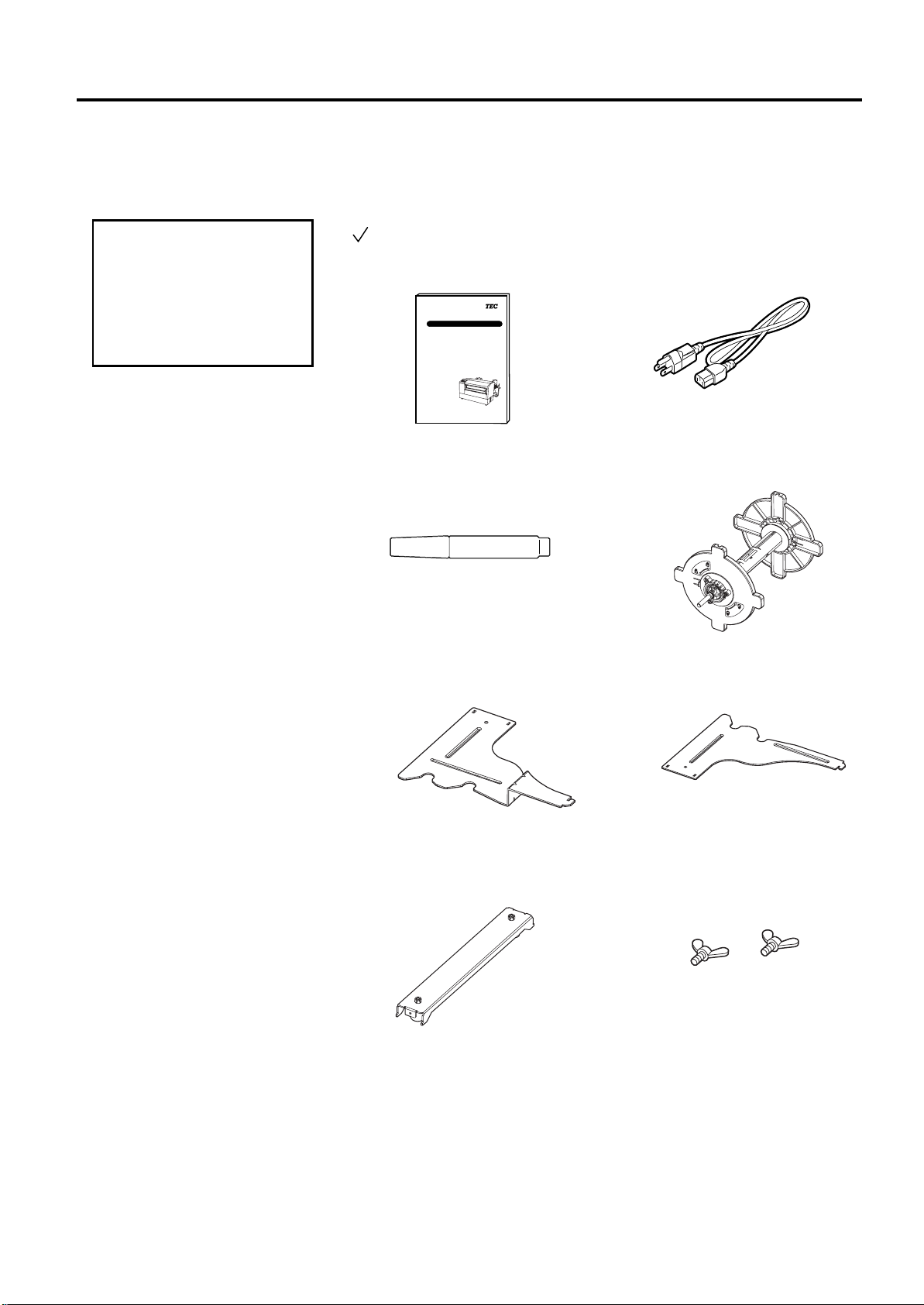
1.4 Accessories
When unpacking the printer, please make sure all accessories are supplied
with the printer.
Owner’s Manual (1 copy)
(Doc./No. EO1-33029)
Print Head Cleaner (1 pc.)
(P/No. 24089500013)
Supply Holder Frame (L) (1 pc.)
(P/No. FMED0035201)
Supply Holder Base (1 pc.)
(P/No. FMBB0063401)
TEC Label/Tag Printer
B-850-TS-12-QQ
Owner's Manual
TOSHIBA TEC CORPORATION
THERMAL HEAD CLEANER
Power Cord (1 pc.)
(P/No. FBCB0030202)
Supply Holder Unit (1 pc.)
(P/No. FMBD0042701)
Supply Holder Frame (R) (1 pc.)
(P/No. FMED0035301)
Wing Bolt M-4x6 (2 pcs.)
(P/No. X20L406130)
1- 2
Page 9
1. PRODUCT OVERVIEW
D
M
p
16.9 (429)
16.8 (427)
7.1 (181)
9.6 (243)
10.4 (265)
15.2 (385)
EO1-33029
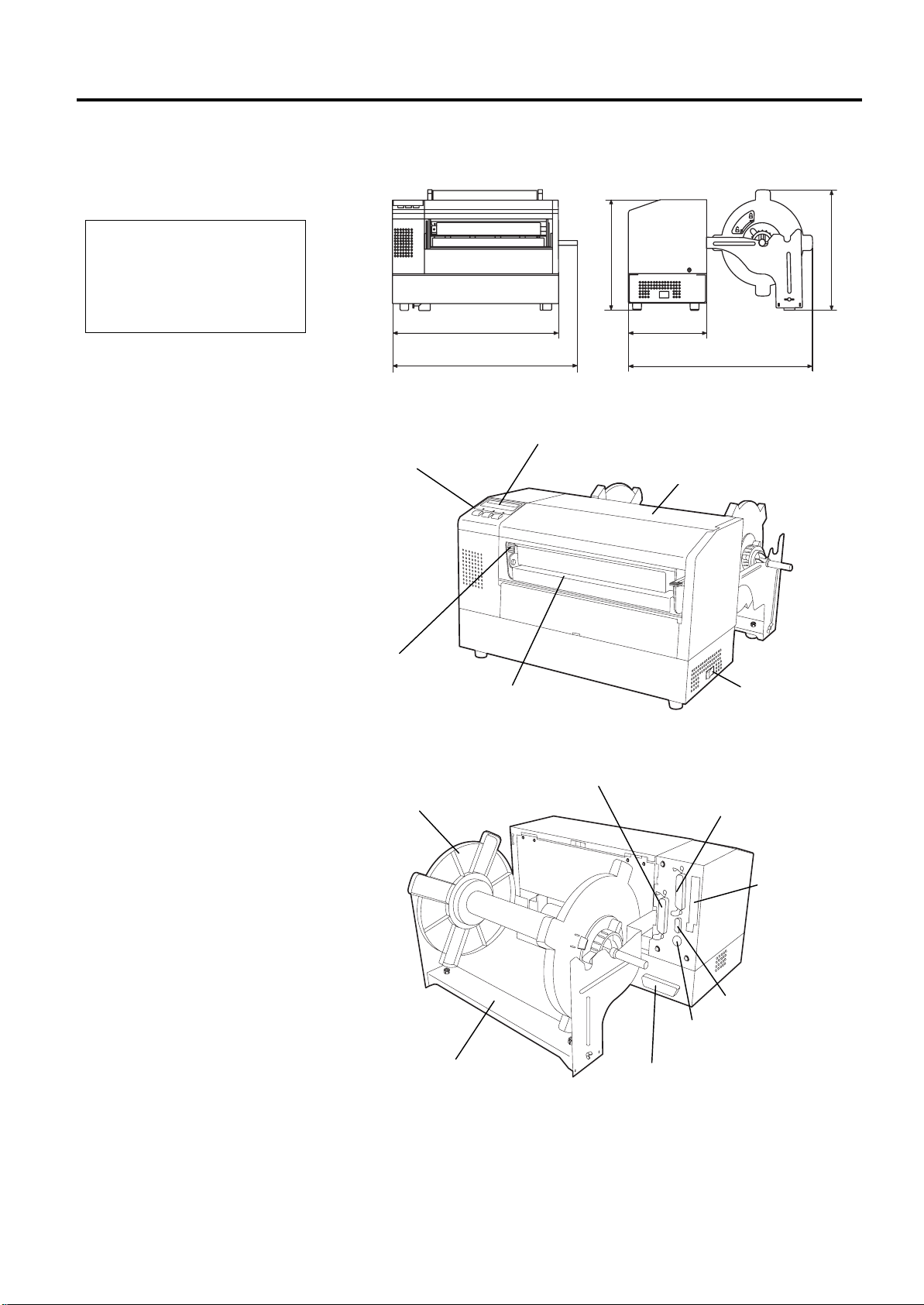
1.5 Appearance
1.5.1 Dimensions
epth is 18.5 inches (470 mm)
when the optional Cutter
odule is installed on the
rinter.
NOTE:
1.5.2 Front View
1.5.3 Rear View
1.5 Appearance
The names of the parts or units introduced in this section are used in the
following chapters.
Operation Panel
LCD Message Display
Dimensions in inches +(mm)
Top Cover
Head Pressure
Adjust Lever
Supply Holder Unit
Media Outlet
Expansion I/O Interface
Connector (Option)
Parallel Interface
Connector (Centronics)
Power Switch
Supply Holder Frame
1- 3
Keyboard Interface
Connector
PCL5 Interface
Connector (Option)
PCMCIA Card
Slot (Option)
Serial Interface
Connector (RS-232C)
Page 10
1. PRODUCT OVERVIEW
EO1-33029
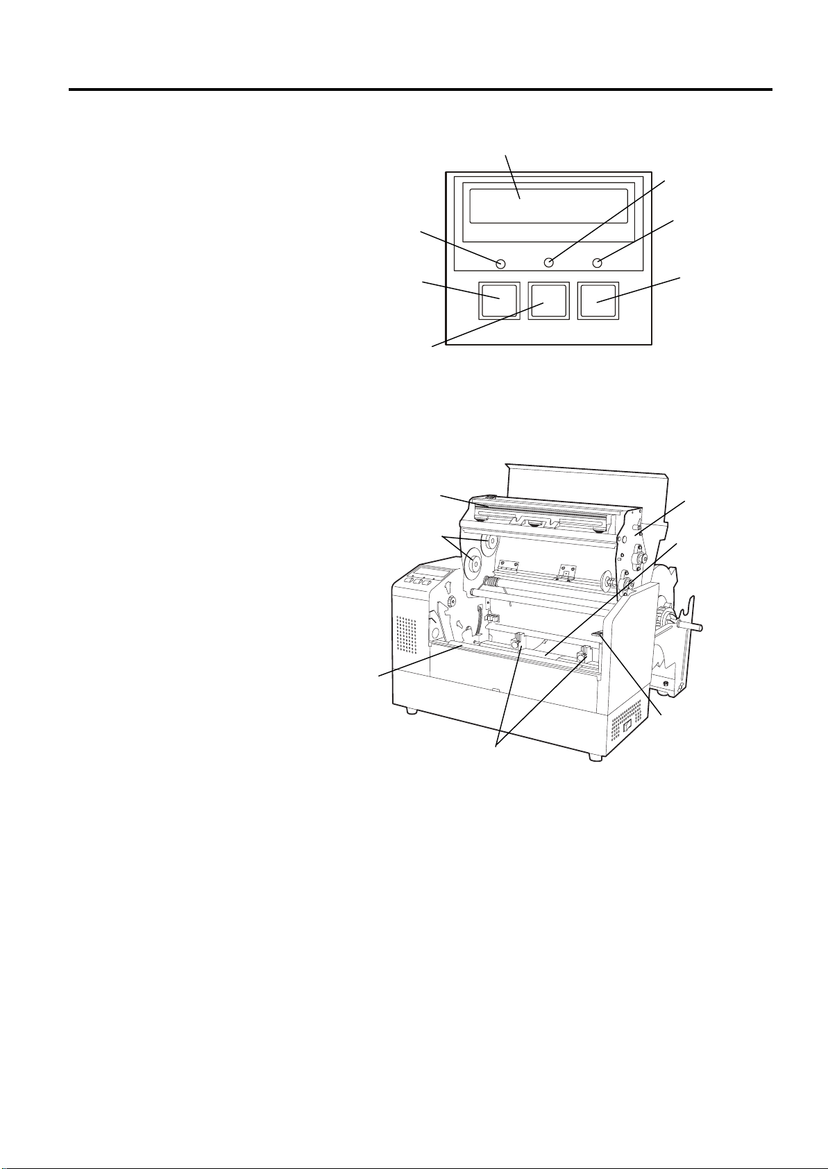
1.5.4 Operation Panel
1.5.5 Interior
1.5 Appearance
POWER LED
(Green)
[FEED]
[RESTART]
Please see Section 4.1 for further information about the Operation Panel.
Print Head
LCD Message Display
POWER ON LINE ERROR
key
key
FEED REST AR T P AUSE
ON LINE LED
(Green)
ERROR LED
(Red)
[PAUSE]
Print Head Block
key
Ribbon Holder
Platen
Paper Guide
Black Mark/
Feed Gap Sensor
Head Block
Release Lever
1- 4
Page 11

2. PRINTER SETUP
EO1-33029
2. PRINTER SETUP
2.1 Precautions
2.1 Precautions
This section outlines the procedures to setup your B-852 printer prior to
its operation. The section includes precautions, connecting cables,
assembling accessories, loading media and ribbon, inserting the optional
memory card, and performing a test print.
• To insure the best operating environment, and to assure the safety of
the operator and the equipment, please observe the following
precautions.
• Operate the printer on a stable, level, operating surface in a location
free from excessive humidity, high temperature, dust, vibration or
direct sunlight.
• Keep y our work environment static free. Static discharge can cause
damage to delicate internal components.
• Make sure that the printer is connected to a clean source of AC Power
and that no other high voltage devices that may cause line noise
interference are connected to the same mains.
• Assure that the printer is connected to the AC mains with a three-
prong power cable that has the proper ground (earth) connection.
• Do not operate the printer with the cover open. Be careful not to
allow fingers or articles of clothing to get caught into any of the
moving parts of the printer especially the optional cutter mechanism.
• Make sure to turn off the printer power and to remove the power cord
from the printer whenever working on the inside of the printer such as
changing the ribbon or loading the media, or when cleaning the
printer.
• For best results, and longer printer life, use only TOSHIBA TEC
recommended media and ribbons.
• Store the media and ribbons in accordance with their specifications.
• This printer mechanism contains high voltage components; therefore
you should never remove any of the covers of the machine as you may
receive an electrical shock. Additionally, the printer contains many
delicate components that may be damaged if accessed by unauthorized
personnel.
• Clean the outside of the printer with a clean dry cloth or a clean cloth
slightly dampened with a mild detergent solution.
• Use caution when cleaning the thermal print head as it may become
very hot while printing. Wait until it has had time to cool before
cleaning. Use only the TOSHIBA TEC recommended print head
cleaner to clean the print head.
• Do not turn off the printer power or remove the power plug while the
printer is printing or while the ON LINE lamp is blinking.
2- 1
Page 12

2. PRINTER SETUP
I
p
p
I
M
EO1-33029
2.2 Procedure before Operation
To communicate with the host
computer, either an RS-232C
cable or Centronics cable is
required.
(1) RS-232C cable: 9 pins
(do not use null modem
cable)
(2) Centronics cable: 36 pins
(3) Expansion I/O cable: 24
pins (Option)
Use of a Windows Driver will
allow issuing media on the B852 printer in place of a
general laser printer from a
Windows application.
nstalling the optional PCL5
interface board in the B-852
rinter allows use of the
drivers which support the
PCL5.
The printer can also be
controlled with its own
rogramming commands.
Please contact your TOSHIBA
TEC reseller for the
nterface/Communication
anual.
NOTE:
NOTE:
2.2 Procedure before Operation
This section describes the outline of the printer setup.
1.
Unpack the accessories and printer from the box.
2.
Refer to Safety Precautions in this manual and set up the printer at a
proper location.
3.
Assemble the Supply Holder Frame and attach it to the rear of the
printer. (Refer to Section 2.3.)
4.
The host computer must have an available serial port or Centronics
parallel port. (Refer to Section 2.4.)
5.
Be sure to insert the power cord plug into an AC outlet. (Refer to
Section 2.5.)
6.
Load the media roll onto the Supply Holder Unit and set it on the
Supply Holder Frame. (Refer to Section 2.7.)
7.
Adjust the position of the Feed Gap Sensor or Black Mark Sensor
depending on the media being used. (Refer to Section 2.8.)
8.
Load the ribbon into the Print Head Block. (Refer to Section 2.9.)
9.
Turn the Power ON. (Refer to Section 2.6.)
10.
Perform a test print. (Refer to Section 2.11.)
11.
Install the Printer Drivers. (Refer to Section 3.)
2- 2
Page 13
2. PRINTER SETUP
M
f
A
f
y
EO1-33029
2.3 Assembling the
Accessories
2.3.1 Assembling the
Supply Holder Frame
ake sure that the two small
langes at each end of the
Supply Holder Base fit into the
small rectangular holes at the
bottom of the Supply Holder
Frames before tightening the
Wing Bolts.
fter attaching the supply
holder frame to the printer,
make sure that it is assembled
irmly.
NOTE:
NOTE:
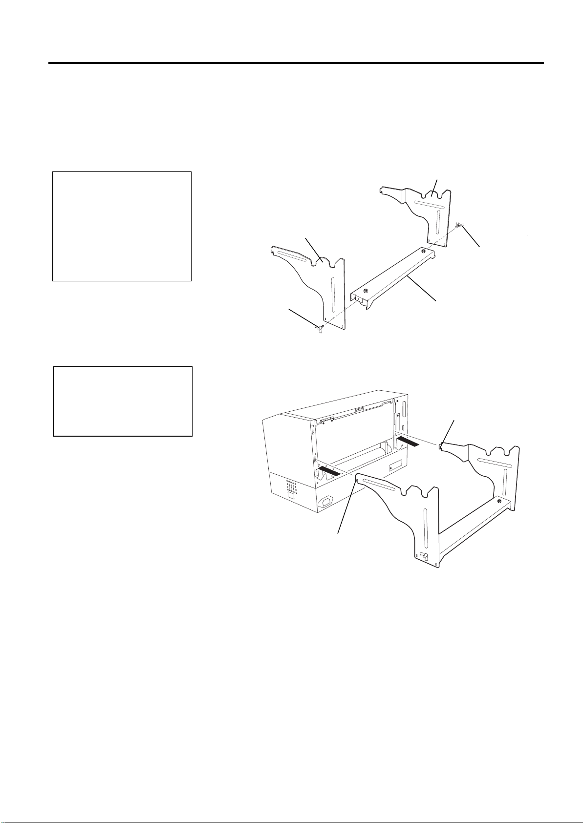
2.3 Assembling the Accessories
The following procedure outlines the steps required to assemble the
Supply Holder Frame and attach the frame to the B-852 printer in
preparation for loading the media.
1.
Assemble the Supply Holder Frame (L) and Supply Holder Frame (R)
to the Supply Holder Base using the two M-4X6 Wing Bolts supplied,
as shown below.
Supply Holder Frame (L)
Suppl
Holder Frame (R)
Wing Bolt
Wing Bolt
2.
Attach the assembled Supply Holder Frame to the rear of the B-852
Supply Holder Base
printer by inserting the hooks of the Frame into the two slots in the
rear of the printer as shown in the figure below.
Hook
Hook
2- 3
Page 14
2. PRINTER SETUP
1
3
4
2
5
EO1-33029
2.4 Connecting the
Cables to Your
Printer
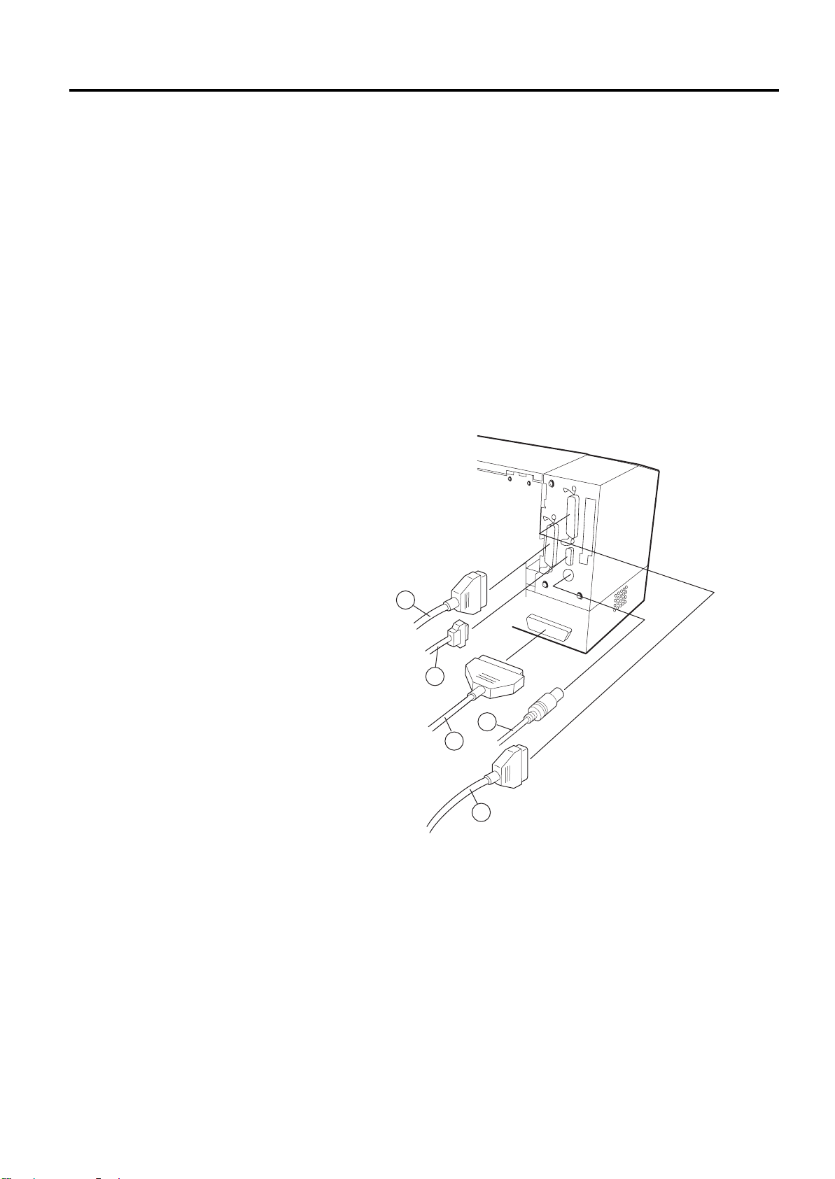
2.4 Connecting the Cables to Your Printer
The following paragraphs outlines how to connect the cables from the B852 printer to your host computer, and will also show how to make cable
connections to other devices such as the KB-80-QM keyboard, etc.
Depending on the application software you use to print labels, there are
three possibilities for connecting the printer to your host computer.
These are:
• A serial cable connection between the printer’s RS-232 serial
connector and one of your host computer’s COM ports.
(Refer to APPENDIX 3.)
• A parallel cable connection between the printer’s standard parallel
connector and your host computer’s parallel port (LPT).
• A parallel cable connection between the printer’s optional PCL5
interface connector and your host computer’s parallel port (LPT).
The diagram below shows all the possible cable connections to the
current version of the B-852 printer.
c Parallel Interface Cable (Centronics)
d Serial Interface Cable (RS-232C)
e PCL5 Interface Cable (Option)
f KB-80-QM Keyboard Interface Cable (Option)
g Expansion I/O Interface Cable (Option)
2- 4
Page 15
2. PRINTER SETUP
EO1-33029
2.5 Connecting the
Power Cord
1. Make sure that the
2. Use only the power
3. Connect the power
CAUTION!
printer power switch is
turned to the off
position
connecting the power
cord to prevent
possible electric shock
or damage to the
printer.
cord supplied with the
printer. Use of any
other cord may cause
electric shock or fire.
cord to a three-prong
outlet only, with the
third prong being a
good ground (earth)
connection.
before
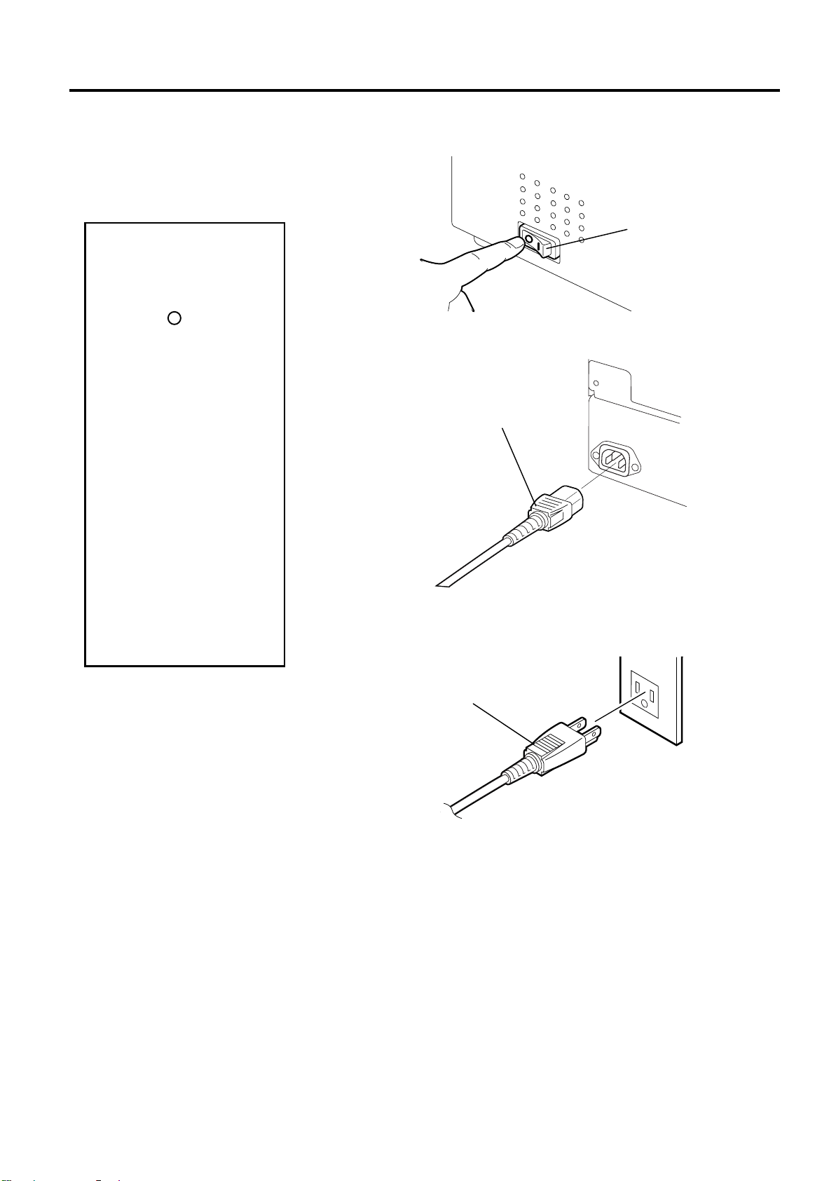
2.5 Connecting the Power Cord
1
. Make sure that the printer power switch is in the off position.
Power Switch
2.
Connect the Power Cord to the printer as shown in the figure below.
Power Connector
3.
Plug the other end of the Power Cord into a grounded outlet as
shown in the figure below.
Power Cord
2- 5
Page 16
2. PRINTER SETUP
I
EO1-33029
2.6 Turning the Printer
ON/OFF
2.6.1 Turning ON the Printer
Use the power switch to
turn the printer On/Off.
Plugging or unplugging
the power cord to turn
the printer On/Off may
cause fire, an electric
shock, or damage to the
printer.
f an error message appears
in the display instead of the
ON LINE message or the
ERROR LED lamp is
illuminated, go to Chapter
6.1, Error Messages.
2.6.2 Turning OFF the
•
Do not turn off the
•
Do not turn off the
CAUTION!
NOTE:
Printer
CAUTION!
printer power while the
media is being printed
as this may cause a
paper jam or damage
to the printer.
printer power while the
ON LINE light is
blinking as this may
cause damage to your
host computer.
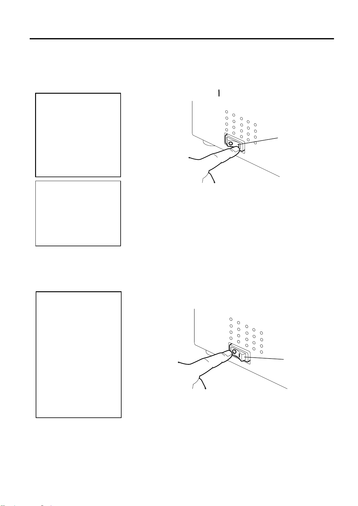
2.6 Turning the Printer ON/OFF
When the printer is connected to your host computer it is good practice to
turn the printer ON before turning on your host computer and turn OFF
your host computer before turning off the printer.
1.
To turn ON the printer power, press the power switch as shown in the
diagram below. Note that ( ) is the power ON side of the switch.
2.
Check that the ON LINE message appears in the LCD Message
Display and that the ON LINE and POWER LED lights are
illuminated.
1.
Before turning off the printer power switch verify that the ON LINE
message appears in the LCD Message Display and that the ON LINE
LED light is on and is not flashing.
2.
To turn OFF the printer power press the power switch as shown in the
diagram below. Note that ( { ) is the power OFF side of the switch.
Power Switch
Power Switch
2- 6
Page 17
2. PRINTER SETUP
1
2
3
y
EO1-33029
2.7 Loading the Media
2.7.1 Installing the Media
onto the Supply Holder
Unit
1. The Non-removable Supply
Holder is the one that
slides in the wide slot while
the Removable Supply
Holder is the one that
slides in the narrow slot.
2. Do not turn the supply
holder locking knob
counter-clockwise too far,
or it may come off the
supply holder Unit.
NOTES:
2.7 Loading the Media
The following procedure will outline the steps required to install the
media onto the Supply Holder Unit and adjust its position in the Supply
Holder Frame at the rear of the B-852 printer. The procedure will then
show the steps to properly load the media into the printer so that it feeds
straight and true through the printer.
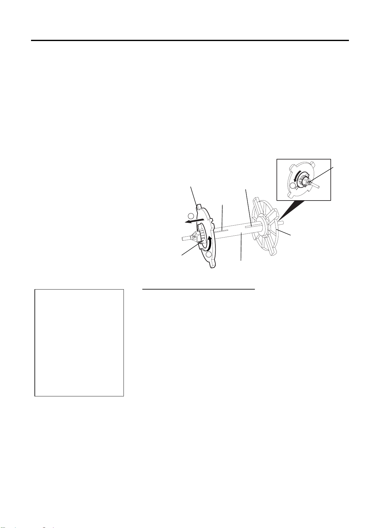
The figure below shows the assembled Supply Holder Unit and the
paragraphs that follow show the step-by-step procedures to disassemble
the Supply Holder Unit, install the media onto the Supply Shaft, then
reassembling the Supply Holder Unit so that the auto centering
mechanism will automatically center the media on the Supply Shaft.
Stopper
Removable
Supply Holder
Narrow Slot
Wide Slot
Green Supply Holder
Locking Knob
Supply Shaft
Non-removable
Suppl
Holder
Disassembling the Supply Holder Unit
1.
Position the Supply Holder Unit as shown in the above diagram so
that the Non-removable Supply Holder is at the right.
2.
Rotate the green Supply Holder Locking Knob in the direction of
arrow
3
. Slide the Removable Supply Holder in the direction of arrow
(counterclockwise) to loosen the Removable Supply Holder.
c
d
to
remove it from the Supply Shaft.
4
. Rotate the green Supply Holder Locking Knob in the direction of
arrow
(counterclockwise) to loosen the Non-removable Supply
e
Holder.
5.
Slide the Non-removable Supply Holder all the way to the end of the
Supply Shaft until it stops.
2- 7
Page 18
2. PRINTER SETUP
1
1
2
EO1-33029
2.7.1 Installing the Media
onto the Supply Holder
Unit (cont.)
2.7 Loading the Media
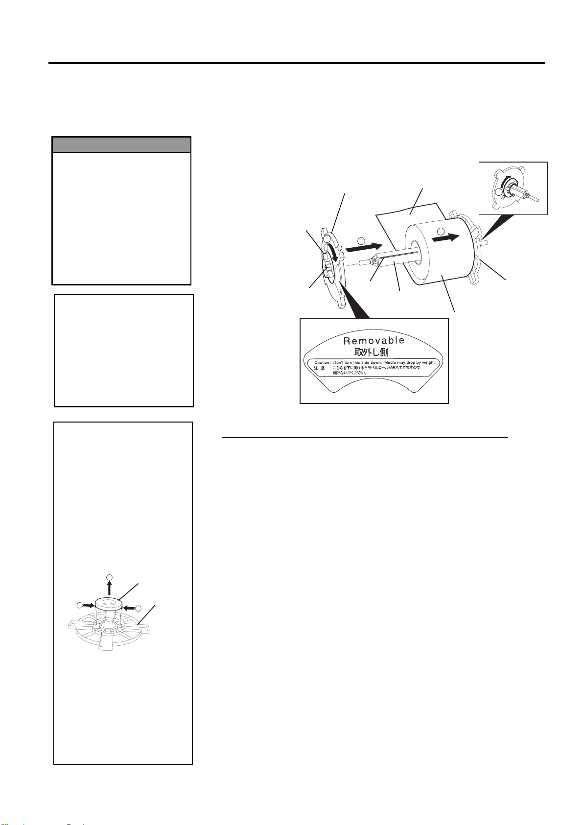
The diagram below, and the steps that follow, show the procedures for
installing the Media onto the Supply Shaft and reassembling the Supply
Holder Unit. Be sure to follow the step-by-step procedure exactly or the
auto centering mechanism may not work properly.
If you turn the
Removable Supply
Holder side down after
loading the media, the
media may drop by
weight. You might be
injured by the dropped
media.
When installing the media
roll, do not push on the
Non-removable Supply
Holder as this will result in
the media roll not being
properly centred.
1. This supply holder accepts
2. Use only inside wound label
3.
WARNING!
CAUTION!
NOTES:
four sizes of media core: 38
mm, 40 mm, 42 mm and 76.2
mm.. When using a media roll
of 38 mm, 40 mm, or 42 mm,
remove the spacers from the
supply holders by pushing
both hooks of the spacer.
Keep the removed spacers
safe.
Spacer
Supply
Holder
stock. Outside wound label
stock may not feed properly.
Use outside wound label stock
at your own risk.
Do not over-tighten the
green supply holder locking
knob.
Removable
Green Supply
Locking Knob
Holder
Supply Holder
3
2
Print Side
4
1
Tab
Slot
Supply Shaft
Media Roll
Non-removable
Supply Holder
Installing the Media and reassembling the Supply Holder Unit
1.
Place the media roll onto the Supply Shaft with the media feeding
from the bottom as shown in the diagram above.
2.
Align the tab of the Removable Supply Holder with the Slot in the
c
Supply Shaft, then reinstall the Removable Supply Holder by sliding it
onto the Supply Shaft as shown in the figure above.
3.
Holding the reassembled Supply Holder Unit in your right hand, apply
pressure only to the reinstalled Removable Supply Holder to push it in
the direction of arrow
, causing the auto centering mechanism to
d
center the media on the Supply Shaft.
4.
Tighten the green Supply Holder Locking Knob for the Removable
Supply Holder by turning it in the direction of arrow
5.
Tighten the green Supply Holder Locking Knob for the Non-
removable Supply Holder by turning it in the direction of arrow
e
.
f
2- 8
.
Page 19
2. PRINTER SETUP
y
M
EO1-33029
2.7.2 Installing the Supply
Holder Unit onto the
Supply Holder Frame
ake sure that the brass
bushings of the Supply Shaft
are seated into the notches so
that the entire Supply Holder
Unit rotates smoothly.
NOTE:
The reassembled Supply
Holder Unit and media roll
may be quite heavy, so
be careful not to pinch
our fingers when
installing the Supply
Holder Unit onto the
Supply Holder Frame.
CAUTION!
2.7.3 Loading Media into
the Printer
The Top Cover can be
opened during the
operation for control
purposes only. It should
be closed during normal
operation.
WARNING!
2.7 Loading the Media
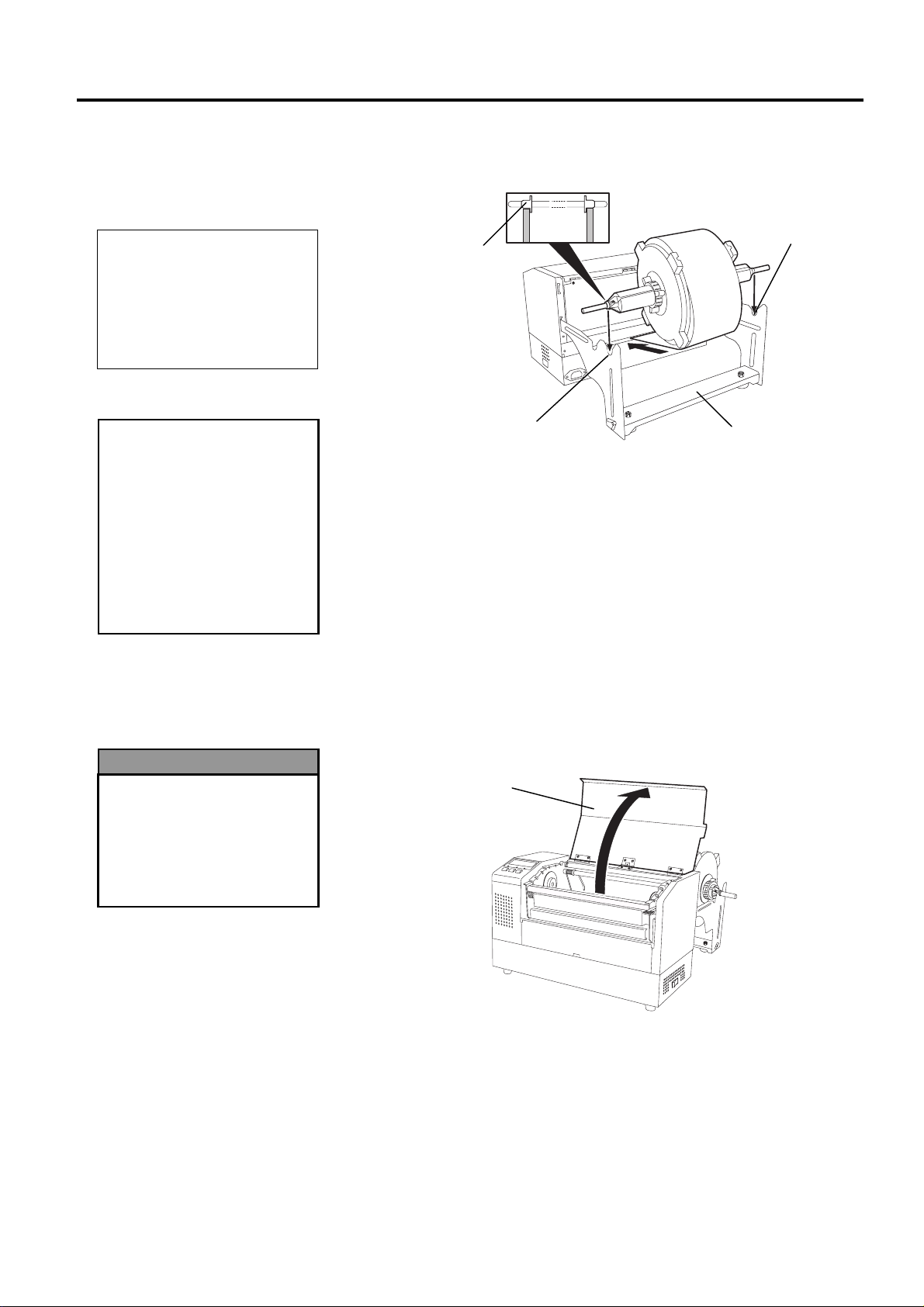
1.
Insert the assembled Supply Holder Unit into the rear notches of the
Supply Holder Frame as shown in the diagram below.
Brass Bushing
Rear Notch
Rear Notch
Supply Holder Frame
2.
Now feed the media from the bottom of the media roll into the media
slot at the rear of the printer as shown.
The following paragraphs outlines how to properly install the media into
the printer from the Supply Holder Unit that has been installed in the
previous steps.
1.
Raise the Top Cover as shown in the diagram below.
Top Cover
2- 9
Page 20
2. PRINTER SETUP
1
2
Lock
Free
EO1-33029
2.7.3 Loading Media into the
Printer (Cont.)
•
•
Be careful not touch the
Print Head Element when
raising the Print Head
Block. Failure to do this
may cause missing dots
by static electricity or
other print quality
problems.
WARNING!
The Print Head may
become hot. Do not
touch the Print Head.
Risk of injuries. Do not
touch moving parts.
Disconnect the mains
before maintenance of
ribbon and media.
CAUTION!
2.7 Loading the Media
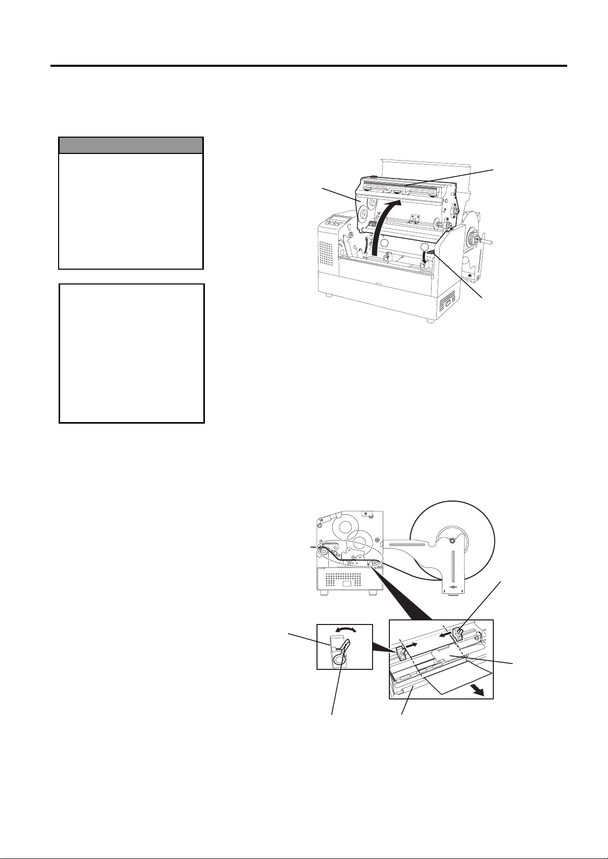
2.
Release the Print Head Block by pressing down on the Head Block
Release Lever
3.
Raise the Print Head Block to its fully open position as shown by the
arrow
in the diagram below.
d
as shown below.
c
Print Head Block
Print Head
Element
Head Block
Release Lever
4.
Release the Paper Guide Locking Levers on the two Paper Guides as
shown in the figure below.
5.
Grasp the right hand Paper Guide and move it to the right to open the
Paper Guides wide enough to accept the media.
6.
Feed the media between the two guides.
7.
Feed the paper under the Upper Sensor Ass’y and pull the paper until
it extends past the Platen. (until it extends past the cutter outlet when
the optional Cutter Module is attached.)
8.
Grasp the right Paper Guide and move it to the left to close both Paper
Guides and automatically center the media.
9.
Press the Paper Guide Locking Levers to lock the Paper Guides in
place.
Paper Guide
Paper Guide
Upper Sensor
Paper Guide
Locking Lever
Platen
Ass’y
2-10
Page 21
2. PRINTER SETUP
EO1-33029
2.7.3 Loading Media into the
Printer (Cont.)
2.7 Loading the Media
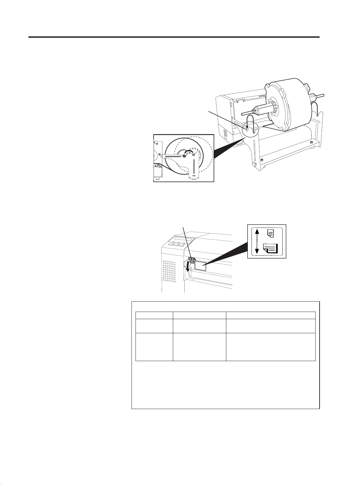
10.
After loading the media, don’t forget to move the Supply Holder
Unit to the forward notches of the Supply Roll Frame as shown
below.
Forward Notch
11.
If you are using labels or thick tag paper, then it may be necessary to
increase the head pressure by lowering the Head Pressure Adjust
Lever in the figure below.
Head Pressure Adjust Lever
UP
DOWN
Lever position Head pressure Available media
UP Low
DOWN High
•
When using full width media, be sure to turn the Head Pressure Adjust
Lever to DOWN, regardless of the thickness.
•
For all kinds of media except the full width media, turn the Head Pressure
Adjust Lever to UP, if the print quality is to be ensured
•
If the print tone is light when using thin tag paper, turn the Head Pressure
Adjust Lever to DOWN.
NOTE: Head Pressure Adjust Lever Position
•Thin tag paper
•Narrow media
•Label
•Thick tag paper
•Wide media
•Full width media
.
2-11
Page 22
2. PRINTER SETUP
EO1-33029
2.8 Setting Sensor
Positions
2.8.1 Setting the Feed Gap
Sensor
2.8.2 Setting the Black Mark
Sensor
2.8 Setting Sensor Positions
After loading the media, as outlined in the previous paragraphs, it will
then be necessary to set the Media Sensors used to detect the print start
position for label or tag printing.
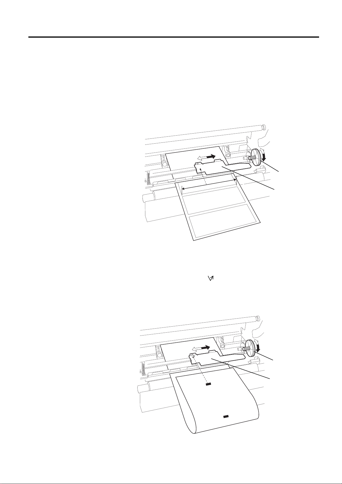
1.
With the Print Head Block raised as described in section 2.7.3, pass
the labels under the Upper Sensor Ass’y as shown in the figure below.
2.
Rotate the Green Sensor Adjust Gear to move the Sensor Ass’y to the
left or right to center the arrow (
3.
With the sensor set to the center of the labels, it will best detect the
↑
) over the label.
gap between labels even if the labels are round.
Green Sensor
Adjust Gear
Upper Sensor Ass’y
1.
If the Black Mark is printed on the top of the tag media then simply
rotate the Green Sensor Adjust Gear to move the Sensor Ass’y so that
the Black Mark Indicator ( ) is directly in line with the Black Mark
on the top of the paper.
2.
If the Black Mark is printed on the bottom of the tag media then fold
the media back to be able to see the Black Mark and its relationship to
the Sensor Ass’y as shown in the figure below.
Green Sensor
Adjust Gear
Upper Sensor Ass’y
2-12
Page 23
2. PRINTER SETUP
B
p
STEP 1
STEP2
3
1
2
1
2
3
EO1-33029
2.9 Loading the Ribbon
•
•
•
e sure to remove any slack in
the ribbon. Printing with a
wrinkled ribbon will lower the
rint quality
WARNING!
The Print Head may
become hot. Do not
touch the Print Head.
The Top Cover can be
opened during the
operation for control
purposes only. It
should be closed during
normal operation.
Risk of injuries. Do not
touch moving parts.
Disconnect the mains
before maintenance of
ribbon and media.
NOTE:
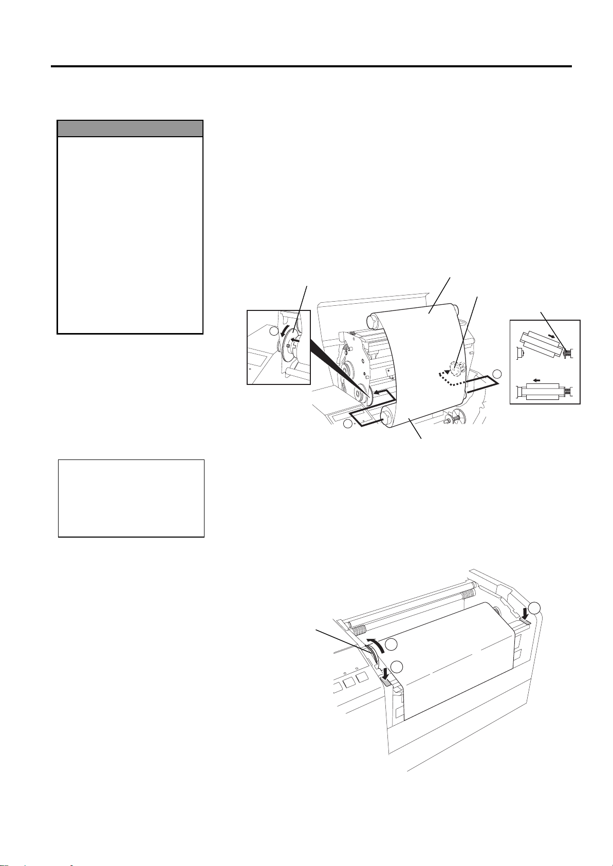
2.9 Loading the Ribbon
1.
Raise the Top Cover and release and raise the Print Head Block as
described in section 2.7.3, steps 1 and 2.
2.
Hold the Ribbon Supply Roll in your left hand and the Ribbon Take
up Roll in your right hand.
3.
Install the Ribbon Supply Roll into the Print Head Block as shown in
the figure below and described in the following paragraphs.
4.
Step 1, engage the end of the Ribbon Supply Roll Core to the Ribbon
Core Guide
5.
Step 2, engage the opposite end of the Ribbon Supply Roll Core to the
Green Ribbon Winding Core
c
and push to compress the Ribbon Spring.
d
releasing pressure to relax the
Ribbon Spring.
6. Rotate the Green Ribbon Winding Core to lock the Ribbon Supply
Roll into position.
Green Ribbon Winding Core
e
Ribbon Take-up Roll
Ribbon Core Guide
Ribbon Spring
Ribbon Supply Roll
7.
Repeat steps 4 through 6 with the Ribbon Take-up Roll, locking it in
place also.
8.
Take up any slack in the ribbon by rotating the Green Ribbon Winding
c
Core on the Ribbon Take-up Roll in the direction of arrow
9.
Close the Print Head Block and lock it in place by pressing at
d
locations
and e in the figure below.
.
Green Ribbon
Winding Core
2-13
Page 24
2. PRINTER SETUP
5
)
EO1-33029
2.10 Inserting the
Optional PCMCIA
Cards
1. To protect PC cards,
2. Before inserting or
3. Be sure to protect
4. Do not subject the card
. The card may be
CAUTION!
discharge static
electricity from your body
by touching the metal
cabinet of the printer
before touching the card.
removing a PCMCIA
card make sure that the
printer’s power is turned
off.
PCMCIA Cards when not
in use by putting them
into their protective
covers.
to any shocks or
excessive force nor
expose the card to
extremes in temperature
or humidity
inserted into the slot
halfway even in the
wrong orientation.
However, the slot is
safety designed so that
the card will not seat
against the connector
pins.
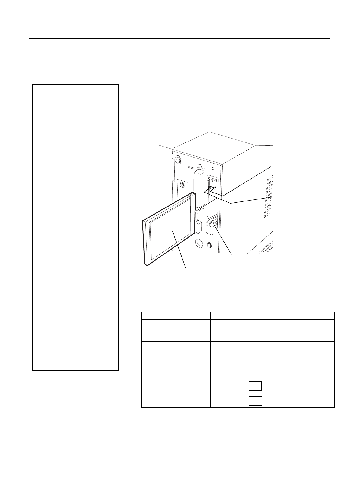
2.10 Inserting the Optional PCMCIA Cards
When the optional PCMCIA interface board is installed into the B-852
printer, there will be two PCMCIA slots available as shown in the figure
below. This allows for the use of Flash Memory Type Cards or I/O type
Cards such as LAN Cards. The following paragraphs outline how to
insert PCMCIA cards.
1.
Make sure that the printer’s power switch is in the OFF position.
2.
Hold the PCMCIA Card so that the model name printed side faces
right. Insert the card into the proper slot until the Eject Button pops
out.
Slot 0:
(Memory type cards only)
Slot 1:
(I/O type cards such as
LAN cards
Model Name Printed Side
Eject Button
3.
The following PCMCIA cards can be used.
Type Maker Description Remarks
ATA Card
San Disk
Hitachi
LAN Card 3 COM
Flash
Memory
Maxell
Card (4 MB)
A card conforming to
the PC card ATA
standard
Ether Link III 3C589D
PC card
Megahertz®
10M bps LAN PC Card
3CCE589ET Series
EF-4M-TB
EF-4M-TB
CC
DC
----------
Install into the slot
(1) only. (This card
installed into the slot
(0) will not work.)
----------
2-14
Page 25

2. PRINTER SETUP
EO1-33029
2.11 Test Print
2.11 Test Print
The following test procedure allows you to perform a print test to verify that
the printer is operating correctly. During the running of this test, the
printer
will first issue a blank page of media to allow the sensors to detect the
Black Mark or Label Gap. Then it will print five pages of slanted lines
followed by five pages of sample bar codes then finishing by printing five
pages that contain characters of various sizes.
Issue count = 5 of each kind of label
Print method = Thermal Transfer (ribbon required)
Print speed = 4” per second
Sensor = Transmissive (Feed Gap Sensor) or Reflective (Black Mark
sensor).
Type of print = Batch (No cut)
Print Length = 76 mm
The following paragraphs guide you through the diagnostic procedure for
test label printing. Please follow the step-by-step procedures exactly for
best results.
1.
Load the media. For best results, use media that is 76 mm or longer in
length.
2.
Press and hold the
[FEED]
and
[PAUSE]
keys while turning on the
printer power switch. The LCD Message Display will show the
following message.
!',$*$
3.
Press the
[FEED]
key three times to advance to the test print mode as
indicated by the following message in the LCD Message Display.
!7(6735,17
4.
Press the
[PAUSE]
key and the LCD Message Display will display
the following message.
35,17&21',7,21
5.
Press the
[RESTART]
key and the LCD Message Display will change
to show the following message.
$87235,175()/
6.
When the media loaded is:
Tag paper utilizing the Black Mark Sensor (Reflective Sensor)
→ Continue on to the next step 7.
Labels utilizing the Feed Gap Sensor (Transmissive Sensor)
→ Press the
[RESTART]
key again, and proceed to step
10.
7.
Press the
[PAUSE]
key and the printer will issue one blank label and
will then print five labels of slant lines and the LCD Message Display
will continue to display the following message.
$87235,175()/
2-15
Page 26
2. PRINTER SETUP
I
p
r
p
p
EO1-33029
2.11 Test Print (cont.)
f an error occurs during the
rint test the printer will
display an error message and
stop printing. Refer to Chapte
6.1 for a definition of error
messages.
The error may be cleared by
ressing the
the test print will not be
resumed and the LCD message
display will return to showing:
When the
ressed in Step 10, the printer
will enter each print pattern
detailed on the setting menu
mode. To exit, press the
[FEED]
at the same time.
NOTE:
[PAUSE]
<1> DIAG. V1.0A
NOTE:
[PAUSE]
[RESTART]
and
key but
key is
keys
2.11 Test Print
8.
Press the
[PAUSE]
key again and the printer will now print five
labels of sample bar codes lines and the LCD Message Display will
continue to display the following message.
$87235,175()/
9.
Press the
[PAUSE]
key again and the printer will now print five
labels of characters of various sizes and the LCD Message Display
will return to showing the test print start message as shown below.
!7(6735,17
10.
Upon pressing the
[RESTART]
key for the second time in step 6,
the LCD Message Display will change to that shown below.
$87235,1775$1
11.
Press the
[PAUSE]
key and the printer will issue one blank label
and will then print five labels of slant lines and the LCD Message
Display will continue to display the following message.
$87235,1775$1
12.
Press the
[PAUSE]
key again and the printer will now print five
labels of sample bar codes lines and the LCD Message Display will
continue to display the following message.
$87235,1775$1
13.
Press the
[PAUSE]
key again and the printer will now print five
labels of characters of various sizes and the LCD Message Display
will return to showing the test print start message as shown below.
!7(6735,17
14.
If necessary, the print test may now be repeated from step 4.
15.
When you have finished performing the test print operation, turn the
printer’s power OFF then back to ON and check that the LCD
Message Display shows
POWER
LED lights are illuminated.
ON LINE
and that the
ON LINE
and
2-16
Page 27
2. PRINTER SETUP
EO1-33029
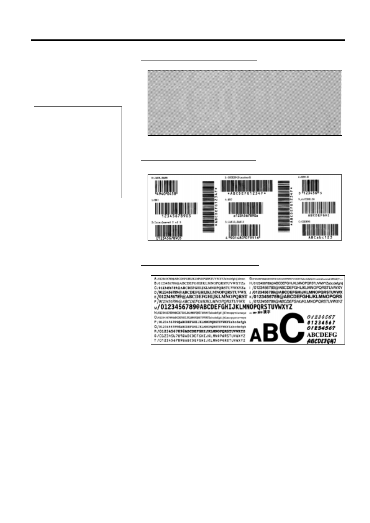
2.11 Test Print (cont.)
The five printed labels of bar
codes and the five printed
labels of characters will be
76mm in length regardless of
the actual size of the labels
installed. However the slant
line printed labels will be the
same size as the installed
labels.
NOTE:
Example of the slant line test print label
Example of the bar code test print label
Example of the character test print label
2.11 Test Print
2-17
Page 28
3. PRINTER OPERATION
EO1-33029
3. PRINTER OPERATION
3.1 Overview
3.2 Operating Modes
This section provides a functional overview of how the printer receives print
data from your host computer and how it will operate in the various
operating conditions. This section also shows you how to install the TEC
Printer Drivers into your computer.
Labels will be created on the host computer connected to your printer,
using either a commercially available label creation program or using the
TEC Command Program Language. Or if the optional PCL5 Interface
Board has been installed, the printer will be able to print from any
software using the HP-PCL5 Printer Command Language. The label
information sent from your host computer will consist of a series of
commands that inform the printer of the labels size, layout, orientation,
and number of copies to print and will also contain the print data
including scaleable text, graphics, and bar codes. The printer electronics
will decode the commands and manipulate the data to create a bit graphic
image of the label that will be stored in the printer’s memory . The printer
electronics will then transfer the image as a series of dots, one line at a
time, to the thermal print head.
The thermal print head consists of a line of 2560 thermal elements with
each element shaped like a tiny dot. The dot line is 8.5 inches (216.8
mm) in length resulting in a dot density of 300 DPI. As the paper is
advanced through the printer by the paper feed mechanism, the thermal
head continuously prints the image as a series of dot lines at a resolution
of 300 dots per inch, horizontally and vertically.
Precision feeding and back feeding of the label or tag stock is
accomplished through the use of specialized stepping motors and photosensors. The label gap sensor or the black mark sensor tells the printer
electronics when the label or tag stock is properly positioned under the
head for accureate printing.
1.
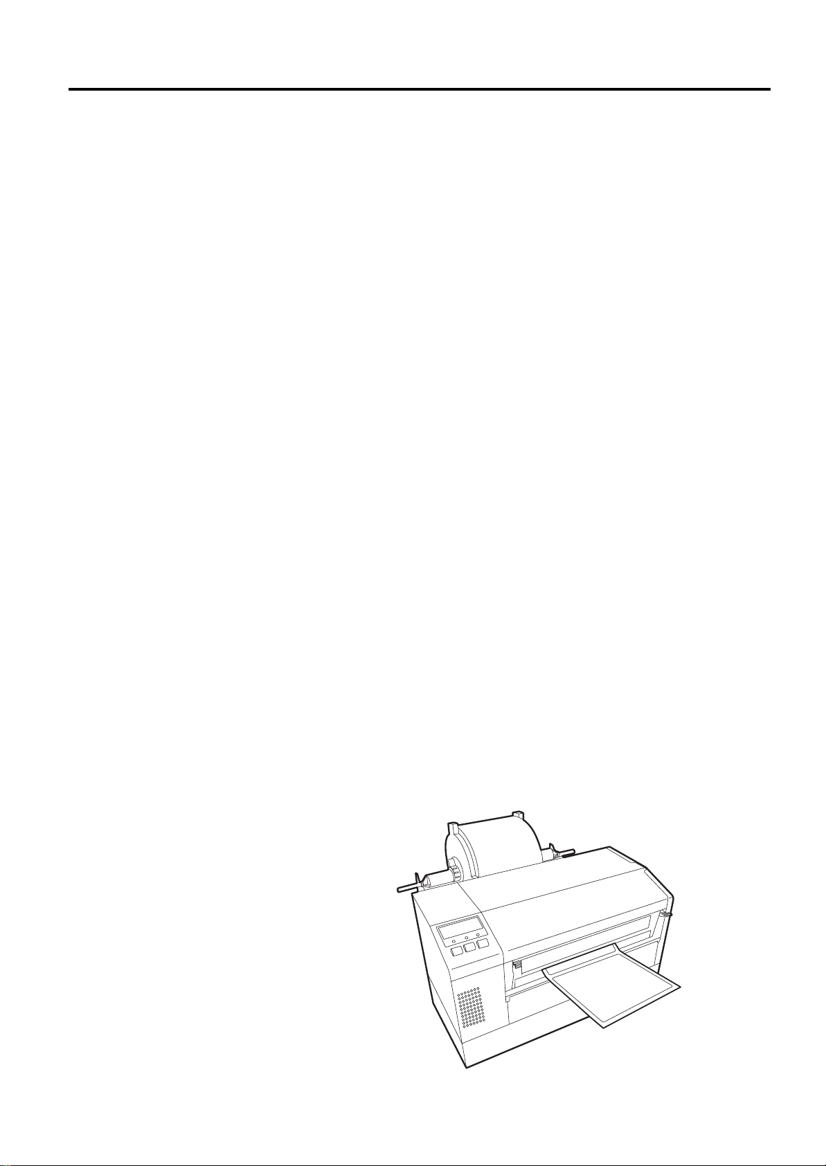
Tear Off Mode – In this operation mode, when the media has stopped
feeding after printing, the label should be in a position that the
operator can simply pull the media downward against the tear off bar
to tear off the printed label.
3.1 Overview
3- 1
Page 29
3. PRINTER OPERATION
EO1-33029
3.2 Operating Modes
(Cont.)
Be sure to cut the
•
backing paper of label.
Cutting labels will cause
the glue to stick to the
cutter, which may affect
the cutter quality and
shorten the cutter life.
Use of tag paper when
•
the thickness exceeds
the specified value may
affect the cutter life.
CAUTION!
3.2 Operating Modes
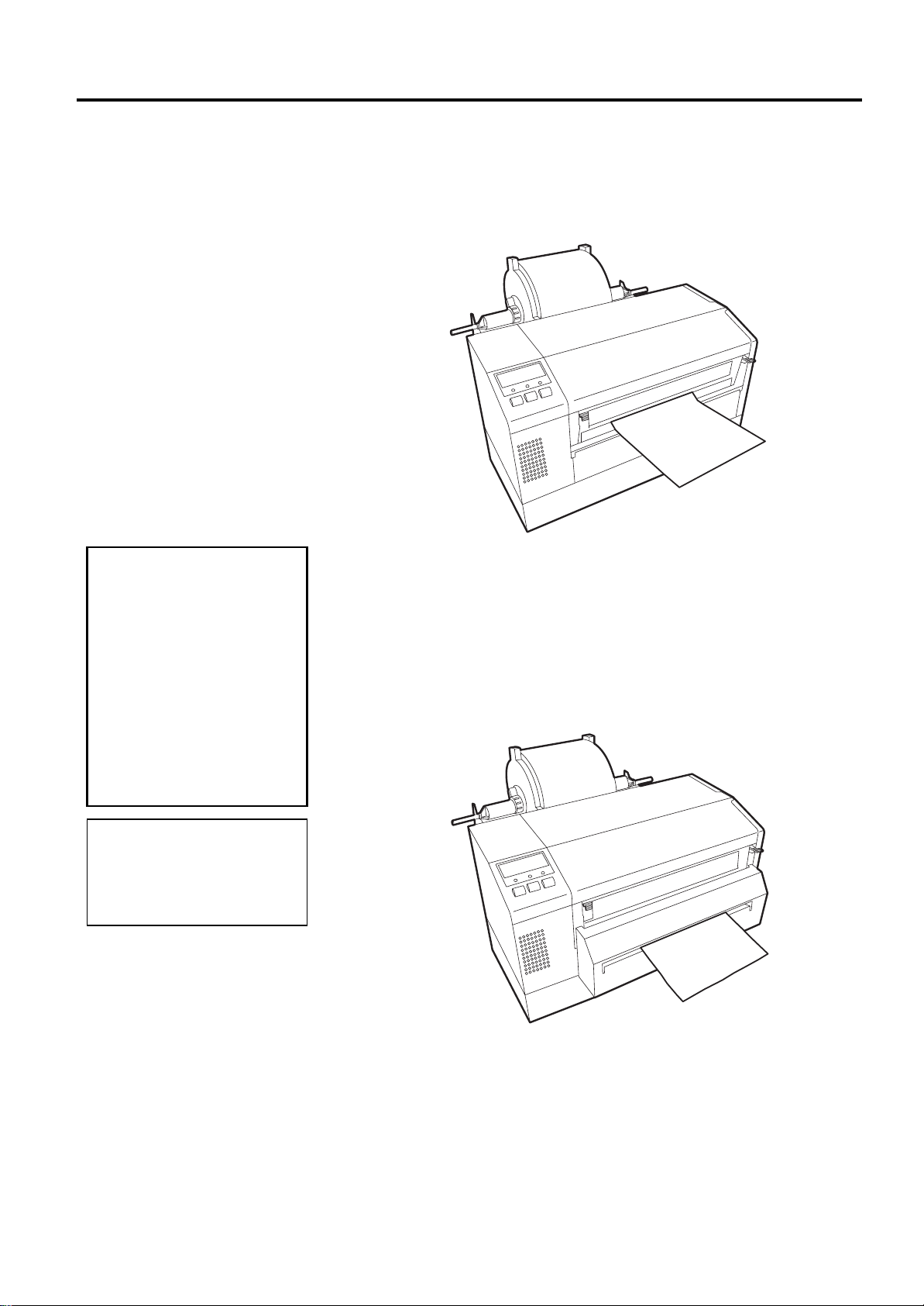
2.
Continuous (or batch) mode – In this mode, the labels will be
continuously printed and fed until the number of labels specified in
the label issue command has been printed. After the last label of the
series has been printed the labels can be torn free from the supply roll
in a similar manner as described in the tear off mode above.
3.
Cut Mode - In the cut mode, as each label is printed it is fed forward
to the cutter mechanism where the swing cutter mechanism will
precisely cut the label off from the supply roll. The feed mechanism
will then backfeed the label or card stock until it is properly positioned
under the print head to print the next label in series. The issue
command sent to the printer from the Host can inform the printer to
cut each label or tag after each has been printed or to perform the cut
only after a certain number of labels or tags have been printed and
issued.
NOTE:
Cut mode is available only when
the optional cutter module
(B-7208-QM) is installed.
3- 2
Page 30
3. PRINTER OPERATION
EO1-33029
3.3 Installing the Printer
Drivers
3.3.1 System Requirements
Windows 3.1® is not supported.
Windows 3.1®, Windows 95®,
Windows 98®, and Windows
NT®
of Microsoft Corporation.
Pentium® is a registered trademark of Intel Corporation
3.3.2 Driver Download
NOTE:
are registered trademarks
3.3 Installing the Pri nt er Dri vers
The TEC MONO Printer Driver is a fi le of driver in formation files to be
used to install TEC monochrome thermal printers to operate under
Windows 95
®,
Windows 98
®,
and
Windows NT®.
Installation is accomplished by first downloading the set of printer driver
files from the TOSHIBA TEC Web Site and transferring the printer
drivers to the hard drive of your host computer. Then using the standard
Windows Add Printer function, the driver for the B-852 will be installed.
Once the driver has been installed, then it becomes quite easy to select
the printer properties dialog and set the parameters for printing.
1.
System
a. IBM Compatible PC running Windows 95® or Windows 98® or
Windows NT® Version 4.0 Workstation or Windows NT®
Version 4.0 Server.
b. Pentium® processor, 133MHz or greater recommended.
c. Installed memory of 16MB minimum (32MB recommended).
d. Available Hard Disk space of 10MB or more.
2.
Interface
a. The RS-232C interface
b. Centronics interface
The following procedures will show you how to obtain the set of TEC
MONO Printer Drivers from the TOSHIBA TEC Barcode Web Site.
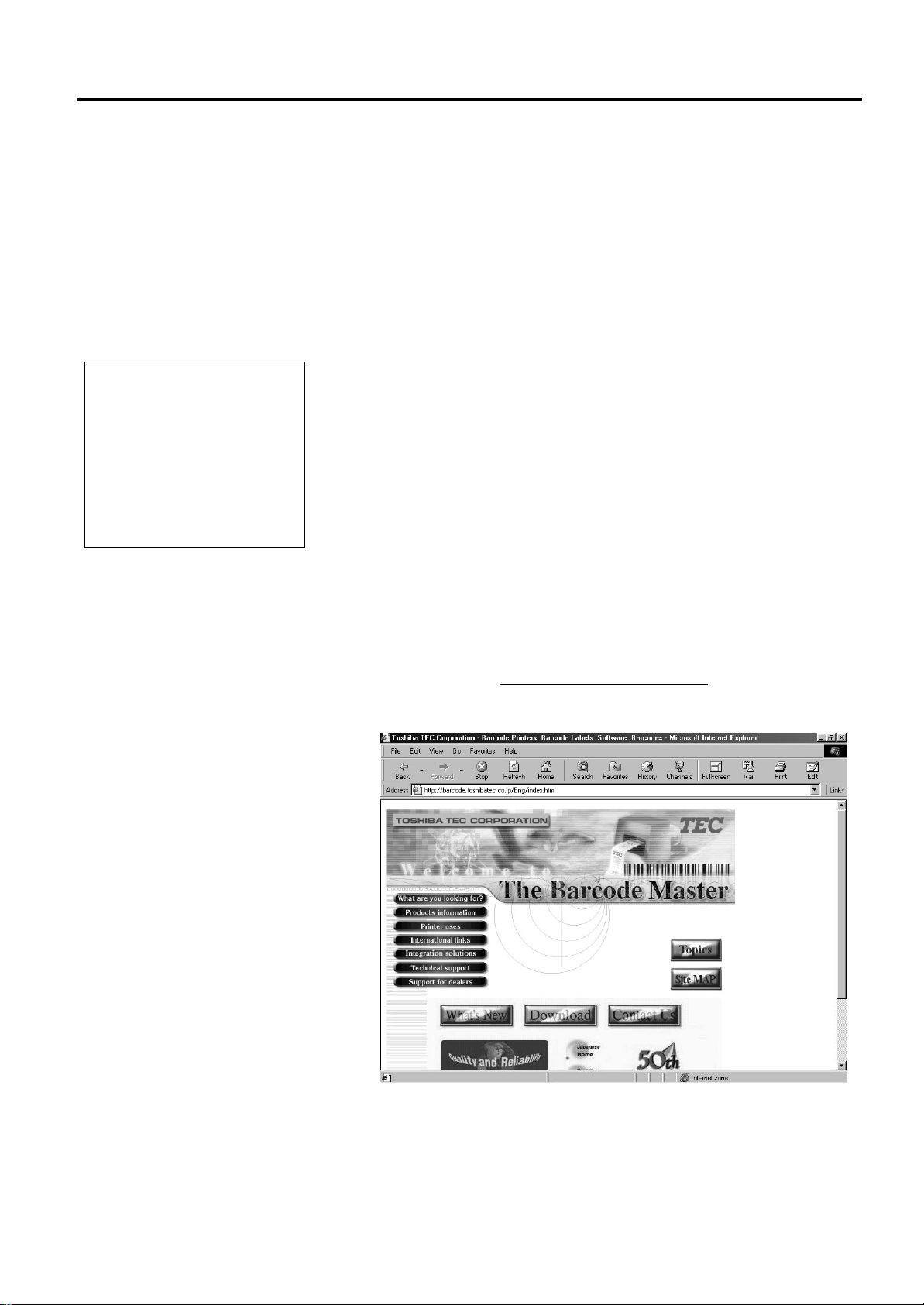
1.
Access the TOSHIBA TEC Barcode World Wide Web Site at the
following URL:
http://barcode.toshibatec.co.jp
After accessing the above web site, the screen will appear as shown below.
3- 3
Page 31

3. PRINTER OPERATION
D
EO1-33029
3.3.2 Driver Download
(Cont.)
3.3 Installing the Printer Drivers
2.
In the previous screen, click on the
Download
button. The screen
will change to the license agreement screen as shown below.
river File name, capacity and
date of the driver may be
changed without prior
notification.
For the latest information about
the driver, please contact your
authorized TOSHIBA TEC
representative.
NOTE:
3.
Read the license agreement and if you accept the terms of the
agreement then click on the
terms then click on the
Accept
Decline
button. If you do not agree to the
button, but you will be unable to
download the drivers.
4.
Upon clicking on the
Accept
button the screen will change to list the
available TEC driver sets. Scroll to locate the screen that lists the set
of Monochrome drivers and lists the B-852 driver as shown by the
screen display below.
5.
Click on the
for WIN95,98&NT
button to begin the download of the
driver set file (“Bdrv_Vx_x_Buildxx.exe”). Be sure to note into
which directory of your hard drive that the browser transfers the file.
6.
Exit from your browser, and using your Windows Explorer, locate the
downloaded file (“Bdrv_Vx_x_Buildxx.exe”). This file will contain
the setup program that will be needed to build the driver files on your
host computer’s Hard disk.
3- 4
Page 32

3. PRINTER OPERATION
y
EO1-33029
3.3.2 Driver Download
(Cont.)
3.3.3 Driver Installation
For further information about
the installation procedure for
Windows NT®, please contact
our authorized TOSHIBA TEC
representative.
NOTE:
3.3 Installing the Printer Drivers
7.
When you locate the file, such as Bdrv_Vx_x_Buildxx.exe, double
click on the file to begin extracting the setup program files. The screen
should appear as shown below.
8.
To extract the driver to the default directory (C:\TEC\MONO\CD)
click on the OK button to begin the extraction. Otherwise click on the
Reference
screen display below.
9.
Select the desired directory to extract the files to and then press the
OK
button to begin the extraction as shown by the following screen
display. (The default directory is shown as the install directory)
Now that the TEC MONO Driver Set has been installed to your hard
disk, the driver setup program must be run to extract the driver
information files to your hard disk preparatory to your adding the B-852
printer function to your host computer.
1.
Locate the driver set that you downloaded in the previous steps. If
you used the default directory, C:\TEC\MONO\CD, go to that
directory.
2.
From that directory, run the Setup.exe program to start the Install
Shield Wizard. The screen will change to that shown below.
button to select a different directory as shown by the
3- 5
Page 33

3. PRINTER OPERATION
I
L
p
EO1-33029
3.3.3 Driver Installation
(Cont.)
f you click the NO button in the
icense Agreement screen, the
rogram will not be installed
NOTE:
3.3 Installing the Pri nt er Dri vers
3.
After the Install Shield temporary files have been loaded, the display
will change to the Welcome screen as shown below.
4.
Click on the
Next
button to continue the installation. The screen will
change to the Software License Agreement screen below.
5.
Carefully read the Software License Agreement. To accept the
conditions of the agreement, click the
Yes
button. If you do not
accept the conditions click on the No button.
6.
Upon clicking on the
Yes
button in the above screen, the display will
change to the Choose Destination Location screen shown below
3- 6
Page 34

3. PRINTER OPERATION
I
N
EO1-33029
3.3.3 Driver Installation
(Cont.)
3.3.4 Add Printers
f you want to use a shared
network printer, you can set it up
quickly by browsing for it in
etwork Neighborhood
the printer's icon, and then
clicking
NOTE:
Install
on the
, clicking
File
menu
3.3 Installing the Pri nt er Dri vers
7.
Click on the
(TEC_DRV\MONO), or click on the
different folder.
8.
Upon clicking on the
copied to the selected folder as shown by the display below.
9.
After all of the files have been transferred the display will change to
the Setup Complete screen below. Click on the
the Setup and return to the Windows desktop.
The previous steps have shown you how to download and install all of
the TEC MONO Printer Drivers. Before you can use the B-852 printer,
its driver must be added using the Windows Add Printer Function.
1.
Click on the Windows
to highlight Settings and click on the
2.
Follow the procedures as outlined in the on screen menus of the Add
Printers Wizard.
3.
Make sure to click on the Have Disk button in the Add Printer Wizard
and indicate the C:\TEC_DRV\MONO folder as the source for the
TEC Printer Driver information files.
Next
button to accept the default Destination Folder
Browse
Next
button the driver files will be extracted and
Start
button and then move the mouse pointer
Printers
button to select a
Finish
icon.
button to end
3- 7
Page 35

3. PRINTER OPERATION
D
y
EO1-33029
3.3.4 Add Printers (Cont.)
3.3.5 Uninstalling the TEC
B-852 Printer Driver
o not uninstall the printer until
ou have closed all applications.
If you are going to install
an upgraded version of the
TEC printer driver you
must first uninstall the
folder “TOSHIBA TEC
PRINTER DRIVER
MONO” by the steps
outlined here.
NOTE:
CAUTION!
3.3 Installing the Pri nt er Dri vers
4.
After the TEC Printer Driver has been successfully loaded, the
Printers screen should appear as shown below, showing the TEC B852 as being successfully installed.
If it becomes necessary to remove the TEC B-852 printer driver from
your host computer, then it can be removed as follows.
1.
In the Printers screen shown above, click on the
highlight it.
2.
Click on the
Delete
screen.
3.
Access the Windows Control Panel and click on the Add/Remove
Programs icon.
4.
The Add/Remove Program Properties window will appear. In this
window, click on
highlight it and then click on the
5.
In the Confirm File Deletion screen that appears, click on the
Yes
File
menu, and when the File sub menu appears, click on
. The icon for the TEC B-852 will disappear from the Printers
TOSHIBA TEC PRINTER DRIVER MONO
Add/Remove
button to complete the removal of the TEC Printer Driver.
TEC B-852
button.
icon to
to
3- 8
Page 36

3. PRINTER OPERATION
EO1-33029
3.4 Using the B-852
Printer Properties
Menus
• The
bottom of the display appears
grayed out for the general
tab, but will be active for
most of the other tabs.
Clicking the
provide some extensive help
screens.
• Clicking on the
the top of the properties
display and then pointing to a
function on the properties
page will result in the
appearance of a small help
message concerning that
function.
• The Apply button at the
bottom of the display should
be clicked after making any
changes to the properties, to
immediately apply the
changes.
NOTES:
Help
button at the
Help
?
button at
button will
3.4 Using the B-852 Printer Propert i es Menus
This section will outline how to use the B-852 Printer Properties menus
to control the printing performance of the printer. The following
paragraphs will show you how to access the Printer Properties menus and
how to change printer settings through these menus.
1.
Access the Printers screen, and then right click on the
icon to access the printer functions menu as shown below.
2.
Highlight and click on Properties in the functions menu as shown in
the screen display above. The TEC B-852 Properties screen will
appear as shown below.
TEC B-852
3- 9
Page 37

3. PRINTER OPERATION
EO1-33029
3.4.1 Summary of Properties
3.4 Using the B-852 Printer Propert i es Menus
The B-852 Properties setting page has eleven tabs to select the different
property setting menus. Clicking on a tab will display the menu
associated with that property allowing you to make changes to the
operation of the printer. The following paragraphs will summarize these
properties.
• General – When clicking on this tab, you can print a test page and
select the composition of separator pages if used.
• Details – After clicking on this tab you can make changes to printer
port settings, time out settings, and spool settings.
• Color Management – This tab would not be used with the B-852
printer as it is used only for associating color profiles with color
printers.
• Regional Settings – Clicking on this tab will allow you to change the
language that the driver displays and also allows you to specify the
units of measurements (mm, inches, etc.) displayed by the driver.
• Page Setup – Clicking on this tab allows you to specify the default
label size and orientation and create new labels or edit existing labels,
and to specify the number of labels to be printed.
• Graphics – Clicking on this tab allows you to select the printer
resolution, dithering method, and print intensity (darker or lighter).
• Bar Fonts – Clicking on this tab allows you to add new bar code
fonts, edit existing bar code fonts, delete existing bar code fonts, or
import and export bar code fonts as *.sbf files.
• Stock – Clicking on this tab will allow you to select the print method,
sensor type, set label gap, select issue mode and specify cutter use,
set print speed (2 or 4 inches per second), and make fine adjustments
to print feed, backfeed, cut, and strip positions.
• Options – Clicking on this tab allows you to select graphic transfer
mode and to adjust the print density in direct thermal or thermal
transfer mode.
• Testing – Clicking on this tab allows you to print a test label, send a
file to the printer, check the thermal head for broken pins, set print
logging options and view or clear the log, specify ribbon settings,
feed a label, and cut the last printed label.
• About – Clicking on this tab will provide you with a way to check
the installed driver version, printer capabilities, and system
information, and also to read the software license agreement covering
this driver.
3-10
Page 38

3. PRINTER OPERATION
EO1-33029
3.4.2 General Properties Tab
• If you share this printer, the
comment will be displayed on
computers that share this
printer. However, if you
change the comment, the
updated version will not
appear on the other computers
unless the printer is
reinstalled.
• Separator pages are useful if
many people are using your
printer or if you are printing
multiple documents at once.
• A separator page can be a full
page that includes graphics or
a simple page with text only.
• You can use any Windows
metafile (.wmf) for a separator
page.
• You can set up separator
pages only if the printer is
attached directly to your
computer.
NOTE:
NOTES:
3.4 Using the B-852 Printer Propert i es Menus
This property will allow you to set up a comment, designate a separator
page, or print a test page.
Comment Window - Provides a place for you to add a comment about
the printer; for example, when it is available or what it is used for.
Separator page - Inserts a page between each document printed. If you
want to use a custom separator page, click the
Browse
button to locate
and specify which separator file you want to print between documents.
The display below shows the screen display when the arrow of the
Separator page: scrolling text box has been clicked showing the choices
for a separator page.
Print Test Page
button - Clicking on this button will send a test page to
your printer to verify if it has been properly set up for printing.
3-11
Page 39

3. PRINTER OPERATION
p
EO1-33029
3.4.3 Details Tab
The
print to the following
: scrolling text box
ort
displays the port the printer is
connected to or the path to the
network printer being used.
The print path can be changed
by typing the network path
here, by opening the list and
clicking a different port, or by
clicking the Add Port button
and specifying a new port.
NOTE:
3.4 Using the B-852 Printer Propert i es Menus
This property will allow the necessary functions needed to select, add or
delete a printer port, select a different printer driver, capture additional
network printer ports, designate timeout settings, change spool settings,
and change the port settings. After clicking on the
Details
tab, the
following screen will appear.
Select a Printer Port - The
box, the
Add Port
button, and the
Print to the follow i ng port :
Delete Port
button work together to
scrolling text
allow the selection of a different port than the default port for printing.
The screen below shows what appears when clicking on the arrow of the
Print to the follow i ng port
: scrolling text box.
To print to a file, click
Print to the following
the
port:
NOTE:
scrolling text box.
File
in
Print to the follow ing port:
the
Delete Port...
the
contained on the
Clicking on the
Add Port..
. button will allow adding additional ports to
button will allow the deletion of ports currently
Print to following port:
3-12
scrolling text box while clicking on
scrolling text box.
Page 40

3. PRINTER OPERATION
I
p
EO1-33029
3.4.3 Details Tab (Cont.)
When clicking on the arrow in
the
Print using the
following driver:
text box, a drop down list
appears showing all the
current drivers installed on the
host computer (as in the
display at the right), to allow
the selection of a different
driver from the list.
NOTE:
scrolling
3.4 Using the B-852 Printer Propert i es Menus
Select a Different Printer Driver - The
driver:
scrolling text box works with the
Print using the follow ing
New Driver..
. button to add
new printer drivers to the PC and to select a different driver from the one
currently being used. The current driver will be highlighted in the list.
%
7(& %
f problems occur when
rinting large documents, it
may become necessary to
increase the value of the
Transmission Retry:
timeout setting.
NOTE:
When clicking on the
Driver
as shown above right will
appear. However, when
clicking on the
screen shown at the top of the
next page will appear,
allowing the installation of an
entirely new driver to the host
computer.
NOTE:
New
button, the same screen
Yes
button, the
Not Selected Timeout Setting Box - Allows entering a value to specify
how much time (in seconds) Windows will wait for the printer to be
online before reporting an error.
Transmission Retry Timeout Setting Box - Allows entering a value to
specify how much time (in seconds) Windows will wait for the printer to
be ready to print before reporting an error.
When clicking on any other driver besides the current one from the list,
the following screen display will appear.
Clicking on the
clicking on the
Yes
button will result in the driver being changed, but
No
button will prevent the driver from being changed.
3-13
Page 41

3. PRINTER OPERATION
EO1-33029
3.4.3 Details Tab (Cont.)
3.4 Using the B-852 Printer Propert i es Menus
• Click
Port
• In the
printer port desired to be
captured. Type the network
path, and then click
• In
port
mapped.
NOTES:
Capture Printer
.
Device
Print to the following
, click the port just
list, click the
OK
.
• If spooling is turned off it will
become impossible to pause
print jobs.
•
If this printer is a network
printer and spooling is turned
off, then the print offline
•
If problems occur printing
with the EMF option then try
the RAW option.
NOTES:
Capture Additional Printer Ports - When clicking on the
Printer Port
and mapping it to a network drive. When clicking on
. button it will allow the capturing of a port (LPT1~LPT9)
End Capture
Capture
...it
will end the capture, removing the mapping of a port from a network
drive.
Changing Spool Settings - When clicking on the
Spool Settings...
button the following screen will appear to allow changing of the spool
settings for the printer driver.
3-14
Page 42

3. PRINTER OPERATION
I
p
B
EO1-33029
3.4.3 Details Tab (Cont.)
f using the serial interface
(COM port) for connection to
the B-852 printer, make sure
that the settings here agree with
the settings set in the printer
arameter settings.
NOTE:
3.4.4 Regional Settings Tab
3.4 Using the B-852 Printer Propert i es Menus
Changing Port Settings -
screen that will appear will depend on whether a parallel port (LPT) or a
serial port (COM) is currently highlighted in the
scrolling text box. For example, if one of the COM ports is highlighted
port:
in the
Print to the following port:
When clicking on the
scrolling text box, then
Port Settings
Print to the following
button, the
the following
screen will appear to allow changing the settings for that port.
This properties management screen will allow changing the language and
units of measurement to agree with the region in which these printers are
being used. After clicking on the
Regional Settings
tab the following
display will appear.
NOTE:
y default, the driver will use
the Regional Settings as
specified in the Windows
Control Panel for settings like
language, measurement system,
and decimal point or comma.
3-15
Page 43

3. PRINTER OPERATION
EO1-33029
3.4.4 Regional Settings Tab
(Cont.)
•
If displaying the driver in a
language other than the system
default is desired, choose the
language here. Changes to the
language will not take effect
until the dialog is closed and
opened again.
•
For a language to list here,
there must be a driver
translation in that language
and it must be supported by
the current operating system.
Languages requiring doublebyte character sets, such as
Japanese or Chinese, may not
be available unless running
under the corresponding
version of Windows.
NOTES:
3.4 Using the B-852 Printer Propert i es Menus
Language Selection
text box, the following screen will appear to allow selection of the desired
language to be used in the printer driver property screens.
- By clicking on the arrow in the
Language:
scrolling
•
It is possible to specify a
value in another system of
measurement by typing the
desired units after the name.
For example, if the driver is
set to inches, simply type
“3.5 cm” into any edit
control and it will be
automatically converted into
“1.38 in”.
•
The “Use System Default”
selection will use the system
of measurement that is
currently selected in
Windows Control Panel’s
Regional Settings.
NOTES:
Measurement System Selection
Units:
scrolling text box, the following screen will appear to allow the
- By clicking on the arrow in the
selection of the desired units of measurement.
3-16
Page 44

3. PRINTER OPERATION
t
p
EO1-33029
3.4.5 Page Setup Tab
NOTE:
When specifying a label stock
size different from the existing
label stock sizes, either create a
new label stock size or edit an
existing one. Pushing the New
button brings up the same dialog
as the Edit button, except that
instead of viewing an existing se
of label stock settings, it
rovides a new blank set to set
as desired.
3.4 Using the B-852 Printer Propert i es Menus
The Page Setup properties management screen is the area in which to
specify the label stock, specify the print orientation, specify black on
white or white on black (negative) print, specify the number of labels to
print, and set some advanced options. After clicking on the Page
tab, the following screen will appear.
Setup
Label Stock - In the preceding display, the area dealing with Label Stock
allows configuring the size of the label stock loaded into the printer.
Either specify a previously loaded stock by name through the
scrolling text box, add a new label stock specification to the list, edit a
label stock already on the list, import a stock list file (*.sfm), or export
the current stock list as a *.sfm file. Clicking on the arrow of the
scrolling text box, will reveal a drop down list showing all the current
stock listing as shown in the screen display below.
Name:
Name:
3-17
Page 45

3. PRINTER OPERATION
L
L
H
M
f
EO1-33029
3.4.5 Page Setup Tab (Cont.)
The options available in the
Edit Label Stock dialog are:
abel Stock Name. Used to
display the name of the
existing label stock name that
is being edited or to enter the
name of a new label stock size.
abel Size. Used to specify the
height and width of a label
stock size. Keep in mind that
height and width are relative
to the orientation of the label.
For example, when printing
using portrait orientation,
there may be a label with a
height of 6” and a width of 4”.
owever, when changing the
orientation to landscape, the
height would change to 4” and
the width to 6”.
Exposed Liner Width. Used
to specify the distance between
the edges of the paper backing
the label and the edges of the
label.
ost applications allow
defining page orientation from
within the application, but
many do not allow 180°
rotation of the image. Choose
the default page orientation
rom those shown at the right.
NOTES:
NOTE:
3.4 Using the B-852 Printer Propert i es Menus
By clicking on either the
New
button or the
Edit
button, the following
screen display will appear.
• When the
New
button has been pressed, a new label name, width,
height, and exposed liner widths may be specified and when the OK
button is clicked it will be added to the stock list.
• When the
Edit
button has been pressed, the highlighted label in the
stock list can have its name, width, height, and exposed liner width
changed to new values.
By clicking on the
Portrait, Landscape, Portrait rotated 180
Landscape rotated 180
o
radio buttons,
the print orientation can be
o
, or
changed. The preview page to the left of the orientation buttons will
change to reflect the selected orientation as shown below.
Portrait
Landscape
Portrait
rotated 180°
Landscape
°
3-18
Page 46

3. PRINTER OPERATION
I
p
p
M
f
p
M
f
p
EO1-33029
3.4.5 Page Setup Tab (Cont.)
Copies
The
set to one because most
rograms know how to specify
a copy count to the driver.
anually specify this driver
setting when using programs
that don’t properly take
advantage of a printer’s
copying capability. (In these
cases, be sure to leave copies
set to “1” in the program,
otherwise it will print many
more copies than desired!).
n order to make any changes
to the
will be necessary to have
knowledge of the command
rogramming language used to
send label commands to the
rinter. Information about the
TEC Printer Command Language is provided in TEC’s
External Equipment Interface
anual. Please contact your
TOSHIBA TEC representative
or further information
concerning this manual.
The Advanced Options dialog
allows control of the printer
options for which the printer
driver does not provide
explicit control. This is done
with four fill-in data fields for
user-defined commands. Also
or importing or exporting
reviously specified printer
driver settings.
NOTE:
option is usually
NOTE:
User Commands
NOTE:
, it
3.4 Using the B-852 Printer Propert i es Menus
When the
Negative
check box has been checked, the print will be white
on black. When this check box is unchecked, the print will be black on
white. The preview page to the left of the orientation buttons will reflect
negative or positive print selection.
The up and down arrows of the
Copies:
scrolling text box can be
clicked to increase or decrease the number of copies to be printed.
When the
Advanced Options
button has been clicked, the screen
display will change to that shown below.
Additional Advanced Options
Printing Preferences - The following settings will allow saving or
exporting the settings of this printer driver so that they may be imported
into a different or freshly installed printer driv er. It also allows importing
previously saved settings to replace the current settings of this printer
driver. The settings will be exported into a file name created and will
have a SDM extension (*.sdm)
•
Import
- Allows importing previously saved printer driver settings.
The settings that can be imported depend on which printer driver is
being used.
•
Export
- Allows exporting the settings of this printer driver. The
settings that can be exported depend on which printer driver is being
used.
3-19
Page 47

3. PRINTER OPERATION
EO1-33029
3.4.5 Page Setup Tab (Cont.)
This Setting is for
advanced users only. Do
not change this setting
otherwise.
3.4.6 Graphics Tab
WARNING!
3.4 Using the B-852 Printer Propert i es Menus
Enable Device Line Substitution
- Most applications draw lines as a
graphic, rather than using line comm ands built- in to the printer. With this
feature enabled, the driver will try to use the printer's line commands to
draw lines and boxes whenever possible. Some applications do not
always print correctly with this feature enabled. Enabling this feature
will cause vertical or horizontal lines to be recognized as a printer
command rather than a graphic.
Minimum Length
. - The minimum length of a line that is to be
recognized as a printer command.
Unprintable Width
- Setting the Unprintable Width allows making
minor adjustments in the horizontal positioning of the printed image on
the label. The distance from the edge of the label stock being used to the
print head may be slightly different than the default setting in the driver
due to manufacturing differences. Making small adjustments to this
number can help compensate for the difference and obtain a more
accurate object placement.
The options that are available on the Graphics property page allow
specifying how text and images will be printed on the label. When
clicking on the
Graphics
tab the following screen display will appear.
Resolution
- This scrolling text box will show the printers possible
resolution settings. On the B-852 only one resolution is available, 300 dpi
x 300 dpi.
3-20
Page 48

3. PRINTER OPERATION
M
EO1-33029
3.4.6 Graphics Tab (Cont.)
any Windows programs allow
designing with different colors
and shades of gray, even though
the thermal printer only prints in
one color: black. By outputting
different black dot-patterns,
each color can be translated into
what appears to be a different
shade of gray on the printer.
NOTE:
3.4 Using the B-852 Printer Propert i es Menus
Dithering
- Creating the illusion of different shades of gray by varying
the
pattern of dots. Close observation reveals that varying the patterns of
black and white dots produces different shades of gray. There are no gray
dots at all. The more dither patterns that a device or prog ram supports, the
more shades of gray it can represent. This screen allows making the
following selections for dithering.
None
•
. Outputs the sharpest images when printing bitmap graphics that
contain only black and white, but no colors or grays.
•
Coarse.
Does the best job of printing lots of different shades of gray,
but will but will soften the edges of graphic images the most.
Fine.
•
Retains greater clarity in higher resolution graphic images than
than the “Coarse” setting, but can’t print as many different shades of
gray.
Line Art
•
. The “Line Art” dithering method uses patterns optimized
for printing line art, rather than general purpose images.
Error Diffusion
•
. Uses a more complex algorithm to avoid the
patterned look of the “Coarse” or the “Fine ” setting.
Intensity
- The intensity of the printed label can be adjusted with the
slider bar from 0 (darkest) to 200 (lightest). Default value is 100.
Color
- the only selection here on the B-852 series is Monochrome.
3.4.7 Bar Fonts Tab
• Most thermal printers have
internal support for many
different bar code symbologies. Most Windows applications are unable to access
these bar codes directly.
However, it is possible to
create an artificial font that
represents a bar code, and
then this font will be listed and
can be selected within any
Windows application that
supports printer fonts. At print
time, the font is converted by
the driver into the desired bar
code.
• Some symbologies will have
minimum and maximum data
lengths, or only accept certain
characters. The bar font
functionality in this driver will
properly filter, format and add
necessary characters to bar
codes before they are printed.
NOTES:
This Property Page will allow adding, deleting, modifying, importing,
exporting, and viewing currently defined bar code fonts. These fonts will
be listed in many Windows applications that normally do not support
printing bar codes. Although they will not appear as bar codes on the
screen, they will print as bar codes. An unlimited number of bar fonts
can be created, each of which may have different bar code parameters.
Upon pressing the
Bar Fonts
tab the screen display below will appear.
3-21
Page 49

3. PRINTER OPERATION
EO1-33029
3.4.7 Bar Fonts Tab (Cont.)
3.4 Using the B-852 Printer Propert i es Menus
The above window has the following functions:
• Bar Fonts View List. This window will display a list of all bar code
fonts currently set up and their resolution they were created at in dots
per inch (dpi). The status bar at the bottom of this list will display
information about the currently selected font.
New
•
button. Allows adding a new bar font. If a font in the view
window is selected, the new bar code font settings will be copied
from the currently selected bar code font.
Edit
•
•
•
•
button. Allows modifying the currently selected bar code font.
Delete
Import
previously been exported.
Export
button. Allows removing the currently selected bar code font.
button. Allows importing a list of bar code fonts that have
button. Allows exporting the current bar code font list to a
file. This file can be loaded into the driver on a different host
computer, and even a different operating system.
• Show Supported Bar Fonts Only. Checking this box limits the view
of bar code fonts to only those supported by the current printer.
Whenever the
New
button or the
Edit
button is pressed, the following
screen display will appear:
Options on the Edit Bar Code Font property page above, will allow
specifying exactly how the printed bar code should appear on the
document or label.
3-22
Page 50

3. PRINTER OPERATION
p
H
EO1-33029
3.4 Using the B-852 Printer Propert i es Menus
3.4.7 Bar Fonts Tab (Cont.)
The Edit Bar Code Font
roperty page will display
different options depending on
which bar code symbology is
selected. For example, if the
Symbology option is set to
“Interleaved 2-of-5,” the only
symbology-specific option tha t
will be displayed is Check Digit.
owever, if the Symbology
option is set to “Code 128,” the
symbology-specific area will
also display the UCC/EAN-128
and Code Set options.
NOTE:
Bar Code Options:
• Symbology. Used to specify the symbology (bar code language) for
bar codes.
• X dimension. Used to specify bar code density using the narrow bar
"X-dimension." (Used with all symbologies except US Postnet.)
• Bar Code Orientation. Used to change the vertical or horizontal
orientation of an object on the label.
• Human Readable. Used to specify the position and visibility of the
human readable characters displayed with the bar codes on the labels.
• Ratio. Used to specify the wide-to-narrow element ratio of the bar
code. (Used with Full ASCII 3-of-9, Regular 3-of-9, Codabar,
Interleaved 2-of-5, and MSI Plessey only.)
Symbology Specific Options:
• Check Digit. Used to specify whether or not check digits will be
added to bar codes. (Used with Full ASCII 3-of-9, Regular 3-of-9,
Interleaved 2-of-5, and MSI Plessey only.)
• UCC/EAN-128. Used to specify whether or not the Software will
automatically add certain characters and perform certain functions
required to print UCC/EAN-128 bar codes. (Used with Code 128
only.)
• Code Set. Used to specify which of the three Code 128 characters sets
(Code A, Code B, or Code C) will be used to print Code 128 bar
codes. (Used with Code 128 only.)
• Version. Used to select one of several supported sizes of Code One.
(Used with Code One only.)
• UCC/EAN FNC1 Prefix. Used to specify whether or not the first
character in a Code One bar code should be the UCC/EAN FNC1
character. (Used with Code One only.)
Symbology Specific Options: (continued)
• Correction Level. Used to specify one of nine levels of error
correction for PDF417 bar codes. (Used with PDF417 only.)
• Truncated. Used to specify that a trimmed-down version of a
PDF417 bar code be printed in order to save space on the label. (Used
with PDF417 only.)
• Row Height. Used to specify the height of each row in a PDF417 bar
code. (Used with PDF417 only.)
• Columns. Used to specify the number of columns in the checkerboard
data area of a PDF417 bar code. (Used with PDF417 only.)
• Start Character. Used to specify which one of the four letters, a - d,
will be used as the start character with a Codabar bar code. (Used with
Codabar only.)
• Stop Character. Used to specify which one of the four letters, a - d,
will be used as the stop character with a Codabar bar code. (Used with
Codabar only.)
• Guard Bar Height. Used to specify the length of the UPC guard bars.
(Used with UPC-A, UPC-E, EAN-13, and EAN-8 only.)
• Supplemental. Used to append UPC supplemental bar. (Used with
UPC-A, UPC-E, EAN-13, and EAN-8 only.)
3-23
Page 51

3. PRINTER OPERATION
B
EO1-33029
3.4.7 Bar Fonts Tab (Cont.)
Pressing the Help button on the
ar Code Font property page
will access additional information concerning each of the
above bar font properties
NOTE:
.
3.4.8 Stock Tab
3.4 Using the B-852 Printer Propert i es Menus
• Symbol Type. Used to specify the type and level of error correction to
use. (Used with Data Matrix only.)
• Character Set. Used to specify the allowable characters for data.
(Used with Data Matrix only.)
• Use Prefix. Used to add a prefix to a bar code. (Used with Data
Matrix only.)
• Shape. Used to specify whether the bar code will print in the shape of
a square or a rectangle. (Used with Data Matrix only.)
• White on Black. Used to reverse the bar code so that it prints white
on a black background. (Used with Data Matrix only.)
• Mode. Used to specify one of the different modes MaxiCode supports.
(Used with MaxiCode only.)
• Zipper Block. Used to specify whether or not a MaxiCode zipper
block will print with the bar code. (Used with MaxiCode only.)
• Contrast Block. Used to specify whether or not a MaxiCode contrast
block will print with the bar code. (Used with MaxiCode only.)
Stock Properties, one of the most important property setting pages. This
page allows the selection of media settings (Ribbon use, sensor type, and
label gap length), issue settings (batch or strip mode, cutter use, and print
speed), as well as fine adjustments (feed length, backfeed length, cut strip
position, and print shrinkage).
After pressing the
Stock
button, the following screen display will
appear.
3-24
Page 52

3. PRINTER OPERATION
p
EO1-33029
3.4.8 Stock Tab (Cont.)
The status of this setting in the
rinter affects the print head
temperature. Accordingly, the
setting must agree with the
label stock that is being used in
order to ensure maximum print
quality.
NOTE:
3.4 Using the B-852 Printer Propert i es Menus
Print Method - The following screen display shows what appears when
the arrow of the
Direct Thermal
without the use of a ribbon.
Thermal Transfer - Select this option when printing with a ribbon.
Sensor Select - The following screen display shows what appears when
the arrow of the
Print Method:
- Select this option when printing on thermal labels or tags
Sensor:
scrolling text box has been clicked on.
scrolling text box has been clicked on.
3-25
Page 53

3. PRINTER OPERATION
I
EO1-33029
3.4.8 Stock Tab (Cont.)
Issue Mode
n
ing is done in Batch Mode (with
back feed).
NOTE:
, Normal print-
3.4 Using the B-852 Printer Propert i es Menus
Sensor Select
• None. Used to specify that either continuous forms (labels without
gaps) are being used or that, if there are gaps or marks, they should be
ignored.
• Reflective. The reflective sensor is used to detect the marks on
continuous stock that has black marks on the back.
• Transmissive. The transmissive sensor is used to locate the gaps
between labels.
• Transmissive (Preprinted Labels). This sets the transmissive
sensor's threshold setting to work better with pre-printed label stock.
• Reflective (Manual Threshold). This allows setting the reflective
sensor's threshold on the printer itself. See the printer's documentation
for information on how to set this threshold.
-
Label Gap
labels. This setting may be set between 2.0 and 20.0 millimeters.
This is the box for typing in the length of the gap
between
Issue Mode – When the arrow on this scrolling text box is clicked on,
only one option will be available and that is batch mode with back feed
since this model printer does not use the strip module.
Cut Mode – When the arrow on the
Cut:
scrolling text box is clicked on,
the following display appears.
3-26
Page 54

3. PRINTER OPERATION
B
p
EO1-33029
3.4.8 Stock Tab (Cont.)
efore executing any large
rint runs, confirm that any
increased speed settings
specified do not result in
unacceptable output quality.
NOTE:
3.4 Using the B-852 Printer Propert i es Menus
When a cutter is installed on the printer, the Cut option is used to enable
the cutter operation and specify how often labels should be cut. The
following settings are available for the Cut option.
• Disabled. This is the default setting.
• After Every Label. Cuts labels after each label is finished printing.
• After Entire Job. Cuts labels only after the entire print job is finished
printing.
Specified Interval
Interval setting. The interval setting window will appear to the right after
clicking on Specified Interval
the interval.
. Cuts labels after the number of labels specified in the
to allow entering in the number of labels for
Print Speed - When clicking on the arrow of the
Print Speed:
scrolling
text box, it will allow the print speed selections of either 2 inches per
second or 4 inches per second.
Fine Adjustment – Allows for adjusting the following parameters. Click
on the Set check box to enable setting fine adjustments through this
property page. If not checked, the fine adjustments are grayed out and
cannot be changed.
• Feed - Specifies the length of label stock that will feed after printing.
• Backfeed - Specifies the length of label stock that is retracted before
printing. This entry window is only available in cut or strip mode.
• Cut/Strip Adjustment - When cutting, this specifies the length of
label to feed before cutting the label. This entry window is only
available in cut mode.
Print Shrinkage - Used to compensate for label print shrinkage or
expansion.
3-27
Page 55

3. PRINTER OPERATION
EO1-33029
3.4.9 Options Tab
3.4 Using the B-852 Printer Propert i es Menus
This page will allow selecting a graphics transfer mode and to make
adjustments to the print tone (lighter or darker print). When selecting the
Options
tab, the following display screen will appear.
Graphic Options
to the printer. The default is to use the fastest method supported by the
printer. When clicking on the arrow in the
box, the following selection screen will appear.
- Allows selecting the method used to download graphics
Transfer Mode:
scrolling text
3-28
Page 56

3. PRINTER OPERATION
EO1-33029
3.4.9 Options Tab (Cont.)
Be careful not to set the
print density adjustment
too high as it can
shorten the life of the
print head. This also
may cause ribbon
tearing if set too high in
thermal transfer mode.
CAUTION!
3.4.10 Testing Tab
3.4 Using the B-852 Printer Propert i es Menus
Print Density Adjustment - Clicking on the
Set:
check box is
necessary to enable the print density adjustment from this property
page. If not checked then no adjustment is possible. When this box is
checked, the screen appears as below.
Print density can be set separately for direct thermal and for thermal
transfer modes. Click on the increase/decrease arrows to adjust the print
density between -10 and +10 in increments of 1.0
This page will allow the execution of certain diagnostic tests and some
additional maintenance settings. When clicking on the
Testing
following screen display will appear.
tab, the
3-29
Page 57

3. PRINTER OPERATION
EO1-33029
3.4.10 Testing Tab
(Cont.)
3.4 Using the B-852 Printer Propert i es Menus
Print Test Label
button - Clicking on this button will print a test label
to assist in troubleshooting printing problems. This should help verify
that the computer being used is communicating with the printer.
Send File to Printe
r... button - Click this button to send a file (*.prn)
irectly to the printer. The driver does no processing on the contents of his
file, and it must already consist of commands understood by the rinter.
Check Print Hea
broken pins test. The test will detect if thermal elements in the print head are
open. A failed test would suggest a need to replace the print head to ensure
perfect print quality. Clicking on this button will bring up the following
display window.
button - This option allows execution of the printer’s
d...
• The
Head:
scrolling text box is only available if the printer happens
to be a color printer, which will allow selection of one of the color
heads.
• The broken pins check is only available on printers containing the
broken pins check circuitry. The B-852 printer does indeed contain the
broken pins check circuit.
• Clicking on the
Specify Range:
check box will allow entering in a
range of elements to check by inputting the starting and ending width
into the two "Specify Range" windows.
•
Click the
printer’s LCD display for a pass/fail message. Failure of this test indicates
that one or more of the head’s thermal elements are open and the thermal
head will need to be replaced.
button to start the test. After starting the test check the
OK
3-30
Page 58

3. PRINTER OPERATION
f
t
p
EO1-33029
3.4.10 Testing Tab
(Cont.)
The Logging Options dialog
supports logging print jobs and
recording printer code to files
or debugging purposes. This
code can be submitted to suppor
ersonnel if problems arise in
the operation of the driver.
NOTE:
3.4 Using the B-852 Printer Propert i es Menus
Logging Options
- When the
Logging Options
button is clicked, the
following display screen will appear.
Logging - Supports logging print jobs and recording printer code to files
for debugging purposes. This code can be submitted to support personnel
if problems arise in the operation of the driver.
Log Print Jobs
•
- This check box must be checked in order to
generate a log file that will list the name of each document and the
printer it was printed to. Jobs are logged in the order they are spooled.
Log File
•
use the
- Into this text box, type the full path name of the log file or
Browse
button to locate an existing log file. It is possible to
share a log file between multiple printers by specifying the same file
name in each driver.
View Log
•
button - View the current log file when this button is
clicked.
Clear Log
•
button - Erase the current log file when this button is
clicked. The next job printed will be the first job in a new log file.
Printer Code Recording -
the print code sent to the printer to a file. Unlike using the Print to File option
in most applications, Printer Code Recording allows printing to the printer
and to a file simultaneously.
•
Record Printer Code
printer code to the specified directory. Each print job will generate a
separate file.
Overwrite Files With Same Name
•
Printer Code Recording allows recording of all of
- This check box must be checked to record
- The driver will name print
code files by adding a .PRN extension to the name of the document
being printed. Normally, if the file already exists, a unique name is
generated by adding a number to the end of the new filename. If this
check box is checked, it will cause the driver to overwrite existing
files.
Directory
•
entered into this text box or the
- Print code files will be recorded to the directory name
Browse
button can be checked to
browse for an existing directory.
File Listing
•
- The window on the left of the dialog is a list of the
print code files in the current directory, to allow performing
operations on individual files using the buttons to the right.
3-31
Page 59

3. PRINTER OPERATION
EO1-33029
3.4.10 Testing Tab
(Cont.)
3.4.11 About Tab
3.4 Using the B-852 Printer Propert i es Menus
View File
•
button - View the currently selected print code file in a
text editor
Send To Printer
•
button - Sends the currently selected print code file
to the printer, effectively printing the job again. If graphics or format
caching was enabled, it may be necessary to send each print file in the
order it was logged to get the desired results.
Delete File
•
button - Deletes the print code file currently selected in
the list.
Delete All Files
•
button - Deletes all print code files in the current
directory and clears the list.
This page will allow checking the driver version information, printer
apabilities, system information and also will display the software license
greement. Clicking on the
About
tab will cause the following screen
isplay to appear.
Clicking on the
License
button in the preceding screen will cause the
following screen display to appear.
3-32
Page 60

3. PRINTER OPERATION
EO1-33029
3.4.11 About Tab
(Cont.)
3.4 Using the B-852 Printer Propert i es Menus
Clicking on the
Version
button in the initial screen will cause the
following screen to appear.
The screen will show the version number of the driver currently installed
into the computer. Clicking on any of the other items in the drop down
list will also display information about the following items:
• Driver Information – Lists additional data about the current driver.
• Systems Information – Lists the Windows and DOS versions
installed in the computer and lists the available drives.
• System Settings – Lists language selections, CRT screen resolution,
and lists the current parameter settings for the serial ports.
• Installed Printers – Lists all printers currently installed in this PC
and lists the drivers and other information about each.
• Installed Software – Lists all the software programs that are
currently installed in the PC.
• Printer Capabilities – Lists all the capabilities (print width, length,
etc.) of this printer.
• Bar Code Capabilities – Outputs a list of all bar codes and indicates
whether each is supported or not supported by this printer.
3-33
Page 61

4. ON LINE MODE
(
)
EO1-33029
4. ON LINE MODE
4.1 Operation Panel
Use the
resume printing after a pause
condition, or after clearing an
error.
NOTE:
[RESTART]
key to
4.1 Operation Panel
This chapter describes usage and purpose of the keys on the Operation
Panel in On Line Mode.
When the printer is in On Line Mode and connected to a host computer,
normal operation of printing images on labels or tags can be
accomplished.
• The figure below illustrates the Operation Panel and key functions.
POWER LED
[RESTART] key
The LCD Message Display shows messages in alphanumeric characters
and symbols to indicate the printer’s status. Up to 16 characters can be
displayed on one line.
There are three LED lights on the Operation Panel.
POWER
ON LINE
ERROR
There are three keys on the Operation Panel.
PAUSE
Green
[FEED] key
LED Illuminates when… Flashes when…
LCD Message Display
POWER ON LINE ERROR
FEED RESTART PAUSE
The printer is turned on. ----The printer is ready to
print.
Any error occurs with
the printer.
Used to stop printing temporarily.
The printer is
communicating with
your computer.
-----
ON LINE LED (Green)
ERROR LED (Red)
[PAUSE] key
RESTART
FEED
Used to restart printing.
Used to feed the media.
4- 1
Page 62

4. ON LINE MODE
I
f
p
p
p
EO1-33029
4.2 Operation
4.2 Operation
4.3 Reset
f the
or less than 3 seconds when the
rinter is in an error or pause
state, the printer restarts
rinting. However, when a
communication error or
command error occurs, the
rinter returns to an idle
condition.
NOTE:
RESTART]
[
key is held
4.4 Dump Mode
When the printer is turned on, the “ON LINE” message appears on the
LCD message display. It is shown during standby or normal printing.
1.
The printer is turned on, standing by, or printing.
21/,1(
2.
If any error occurs during printing, an error message appears. The
printer stops printing automatically. (The number on the right column
shows the number of unprinted media.)
123$3(5
3.
To clear the error, press the
printing.
21/,1(
4
. If the
printing temporarily. (The number on the right column shows the
number of unprinted media.)
5.
When the
Reset operation clears the print data sent to the printer from the computer,
and returns the printer to an idle condition.
1.
The printer is turned on, standing by, or printing.
2.
To stop printing, or clear the data sent from the computer, press the
[PAUSE]
3.
Press and hold the
4.
Press the
cleared, and the printer returns to an idle condition.
In Dump mode, any characters sent from the host computer will be
printed. Received characters are expressed in hexadecimal values. This
allows the user to verify programming commands and debug the
program.
And for other details, please refer to your nearest TOSHIBA TEC service
representative.
[PAUSE]
3$86(
[RESTART]
21/,1(
21/,1(
key. The printer stops printing.
3$86(
!5(6(7
[PAUSE]
21/,1(
key is pressed during printing, the printer stops
[RESTART]
key. The data sent from the computer will be
[RESTART]
key is pressed, the printer resumes printing.
key for 3 seconds or longer.
key. The printer resumes
4- 2
Page 63

5. MAINTENANCE
r
(
)
EO1-33029
5. MAINTENANCE
•
Be sure to disconnect the
Power Cord before
performing maintenance.
Failure to do this may
cause an electric shock.
•To avoid injury, be careful
not to pinch or jam your
fingers while opening or
closing the cover and
Print Head Block.
•
The Print Head may
become hot. Do not
touch the Print Head.
•
Do not pour water directly
onto the printer.
5.1 Cleaning
5.1.1 Print Head/Platen/
Sensors
•
Do not allow any hard
objects to touch the print
head or platen, as this
may cause damage to
them.
•
Do not use any volatile
solvent including thinner
and benzene, as this
may cause discoloration
to the cover, print
failure, or breakdown of
the printer.
•
Do not touch the print
head element with bare
hands, as static may
damage the print head.
•
Be sure to use the print
head cleaner enclosed
with this printer. Failure
to do this may shorten
the print head life.
WARNING!
CAUTION!
5.1 Cleaning
This chapter describes how to perform normal maintenance.
To maintain the printer performance and quality print, please clean the
printer regularly, or whenever media or ribbon is replaced.
The following sections describe periodic cleaning of the unit.
1.
Turn off the printer. Open the Top Cover.
2.
Press the Head Block Release Lever to release the Print Head Block.
3.
Raise the Print Head Block and remove the ribbon.
4.
Clean the Print Head Element with the supplied Print Head Cleaner.
Print Head Cleane
P/No.:
5.
Hold the Sensor Lift Tab and lift the Upper Sensor Ass’y.
6.
Wipe the Feed Gap Sensor and Black Mark Sensor with a dry soft
7.
Wipe the Platen with a soft cloth slightly moistened with ethyl
24089500013
cloth.
alcohol.
Print Head Element
Print Head
Sensor Lift Tab
NOTE:
Please use the TEC approved
Print Head Cleaner which can
be purchased from an
authorized TOSHIBA TEC
service representative.
5- 1
Feed Gap Sensor and
Black Mark Sensor
Platen
Page 64

5. MAINTENANCE
EO1-33029
5.1.2 Covers and Panels
Do not use any volatile
solvents including thinner
and benzene, as this may
cause discoloration or
distortion of the cover.
CAUTION!
5.1.3 Optional Cutter Module
1. Be sure to turn the
2. The Cutter is sharp, so
WARNING!
power off before
cleaning the Cutter
Module.
care should be taken
not to injure yourself
when cleaning.
5.2 Care/Handling of
the Media and
Ribbon
Be sure to carefully review
and understand the Supply
Manual. Use only media
and ribbons which meet
specified requirements.
Use of non-specified media
and ribbons may shorten
the head life and result in
problems with bar code
readability or print quality.
All media and ribbons
should be handled with
care to avoid any damage
to the media, ribbons or
printer. Read the guideline
in this section carefully.
CAUTION!
5.2 Care/Handling of the Media and Ribbon
Wipe the Cover and Front Panel with a dry soft cloth. Wipe off dirt with
a soft cloth slightly moistened with water.
1.
Remove the Plastic Head Screws and to detach the Cutter Cover.
2.
Remove the jammed paper and trash, if any.
3.
Clean the Cutter Blade with a dry cloth.
Cutter Unit
Plastic Head Screw
• Do not store the media and ribbon for longer than the manufacturer’s
recommended shelf life.
• Store media rolls on the flat end. Do not store them on the curved
sides as this might flatten that side causing erratic media advance and
poor print quality.
• Store the media in plastic bags and always reseal after opening.
Unprotected media can get dirty and the extra abrasion from the dust
and dirt particles will shorten the print head life.
• Store the media and ribbon in a cool, dry place. Avoid areas where
they would be exposed to direct sunlight, high temperature, high
humidity, dust or gas.
• The thermal paper used for direct thermal printing must not have
specifications which exceed Na
ppm.
• Some ink used on pre-printed media may contain ingredients which
shorten the print head’s product life. Do not use labels pre-printed
with ink which contain hard substances such as carbonic calcium
(CaCO
For further information, please contact your local distributor or your
media and ribbon manufacturers.
) and kaolin (Al2O3, 2SiO2, 2H2O).
3
+
800 ppm, K+ 250 ppm and Cl- 500
Fixed Cutter
Swing Cutter
Plastic Head Screw
Cutter Cover
5- 2
Page 65

6. TROUBLESHOOTING
N
EO1-33029
6.1 Error Messages
6. TROUBLESHOOTING
This chapter lists the error messages, possible problems, and their solutions.
If a problem cannot be solved by taking actions described in this chapter, do not attempt to repair the
printer. Turn off and unplug the printer. Then contact an authorized TOSHIBA TEC service
representative for assistance.
6.1 Error Messages
OTES:
If an error is not cleared by pressing the
•
After the printer is turned off, all print data in the printer is cleared.
•
“****”
•
HEAD OPEN
HEAD OPEN
COMMS ERROR
PAPER JAM ****
CUTTER ERROR ****
(Only when the Cutter
Module is installed on
the printer.)
indicates the number of unprinted media. Up to 9999 (in pieces).
Error Messages Problems/Causes Solutions
The print head block is opened in Online
Mode.
****
Feed or printing has been attempted with
the Print Head Block open.
A communication error has occurred. Make sure the interface cable is firmly
1. The media is jammed at the media
path. The media is not fed smoothly.
2.
A wrong media sensor is selected for
the media being loaded.
3.
The Black Mark Sensor is not
aligned to the Black Mark on the
media.
4.
Size of the loaded media is not
consistent with the programmed size.
5.
The Feed Gap Sensor cannot
distinguish the print area from a
label gap.
The media is jammed in the Cutter.
1.
2.
The Cutter Cover is improperly
installed.
WARNING!
[RESTART]
key, turn the printer off and then on.
Close the print head block. Then press
[RESTART]
the
Close the print head block. Then press
[RESTART]
the
connected to the computer, and the
computer is turned on.
1.
Remove the jammed media, and clean
the platen. Then reload the media
properly. Finally press the
RESTART]
[
2.
Turn the printer off and then on. Then
select the media sensor supporting the
media being loaded. Finally resend
the print job.
3.
Adjust the sensor position. Then press
[RESTART]
the
Turn the printer off and then on.
4.
Replace the loaded media with one
which matches the programmed size,
or select a programmed size that
matches the loaded media. Finally
resend the print job.
5.
Refer to Section 6.5 to set the
threshold. If this does not solve the
problem, turn off the printer, and call
an authorized service representative.
Remove the jammed media. Then
1.
press the
does not solve the problem, turn off
the printer, and call an authorized
service representative.
2.
Turn the printer off and check the
status of the Cutter Cover.
key.
key.
key.
[RESTART]
key.
key. If this
6- 1
Page 66

6. TROUBLESHOOTING
EO1-33029
6.2 Possible Problems
6.1 Error Messages (Cont.)
Error Messages Problems/Cause Solutions
NO PAPER ****
RIBBON ERROR ****
EXCESS HEAD TEMP
HEAD ERROR
Other error messages Hardware or software problems may
1. The media has run out.
2.
The media is not loaded properly.
The media is slack.
3.
1. The ribbon is not fed properly.
2.
The ribbon has run out.
The print head is overheated. Turn off the printer, and allow it to cool
There is a problem with the Print Head. Replace the Print Head. Then press the
have occurred.
Load new media. Then press the
1.
[RESTART]
2.
Load the media properly. Then press
[RESTART]
the
Take up any slack in the media.
3.
Remove the ribbon, and check the
1.
status of the ribbon. Replace the
ribbon, if necessary. If the problem is
not solved, turn off the printer, and
call an authorized service
representative.
2.
Load a new ribbon. Then press the
[RESTART]
down (about 3 minutes). If this does not
solve the problem, call a TOSHIBA TEC
authorized service representative.
[RESTART]
Turn the printer off and then on. If this
does not solve the problem, turn off the
printer again, and call a TOSHIBA TEC
authorized service representative.
key.
key.
key.
key.
6.2 Possible Problems
This section describes problems that may occur when using the printer, and their causes and solutions.
Possible Problems Causes Solutions
The printer will not
turn on.
The media is not fed. 1. The media is not loaded properly.
Nothing is printed on
the media.
The printed image is
blurred.
The Cutter does not
cut.
1. The Power Cord is disconnected.
2. The AC outlet is not functioning
correctly.
3. The fuse has blown, or the circuit
breaker has tripped.
2. The printer is in an error condition.
1. The media is not loaded properly.
2. The ribbon is not loaded properly.
3. A print head is not installed properly.
4. The ribbon and media are not
matched.
1. The ribbon and media are not
matched.
2. The Print Head is not clean.
1. The media is jammed in the Cutter.
2. The Cutter Blade is dirty.
1. Plug in the Power Cord.
2. Make sure that the power is supplied
using another electric appliance.
3. Check the fuse or breaker.
1. Load the media properly.
2. Solve the error in the Message
Display. (See Section 6.1 for more
detail.)
1. Load the media properly.
2. Load the ribbon properly.
3. Install the Print Head properly. Close
the Print Head Block.
4. Select an appropriate ribbon for the
media type being used.
1. Select an appropriate ribbon for the
media type being used.
2. Clean the print head using the supplied
Print Head Cleaner.
1. Remove the jammed paper.
2. Clean the Cutter Blade.
6- 2
Page 67

6. TROUBLESHOOTING
I
EO1-33029
6.3 Removing Jammed Media
6.3 Removing Jammed
Media
CAUTION!
Do not scratch the Print
Head or Platen using a
sharp instrument, as this
may cause media feed
failure or damage to the
printer.
f you get frequent jams in the
Cutter, contact a TOSHIBA
TEC authorized service
representative.
NOTE:
This section describes in detail how to remove jammed media from the
printer.
Remove the jammed media from under the Upper Sensor Ass’y as
follows:
1.
Open the Top Cover.
2.
Push the Head Block Release Lever to release and raise the Print
Head Block.
3.
Lift the Upper Sensor Ass’y, and remove the jammed media.
4.
Clean the Platen and sensors as described in Section 5.1.1 .
5.
Media jams in the Cutter Module can be caused by conditions such
as wear or residual glue from label stock on the Cutter Blade. Do not
use non-specified media with the Cutter.
Upper Sensor Ass’y
6- 3
Page 68

6. TROUBLESHOOTING
EO1-33029
6.4 Threshold Setting
6.4 Threshold Setting
NOTES:
1. If the [PAUSE] key is
released within 3 seconds
while in pause state, paper
will not feed.
2. Failure to feed more than
1.5 labels may result in an
incorrect threshold setting.
3. While the Print Head Block
is raised, the [PAUSE] key
does not work.
4. Errors such as paper end
and cutter error are not
detected during paper feed.
5. Selecting the Transmissive
Sensor(for pre-printed
labels) within software
commands allows the
printer to detect the proper
print start position
correctly even when using
pre-printed labels.
6. If using the transmissive
sensor and the printer
continues to print out of
position even after setting
the threshold, adjust the
Feed Gap Sensor in the
system mode. Reset the
threshold again. Make sure
that the Transmissive
Sensor (for pre-printed
labels) is selected in the
feed and issue commands.
To maintain a constant print position the printer uses the Transmissive
Sensor to detect the gap between labels by measuring the amount of
light passing through the media. When the media is pre-printed, the
darker (or more dense) inks can interfere with this process causing
paper jam errors. To get around this problem a minimum threshold can
be set for the sensor in the following way.
Threshold setting procedure
1. Turn the power ON. The printer is in stand by mode.
21/,1(
2. Load a media roll.
3. Press the [PAUSE] key.
3$86(
4. The printer enters the pause mode.
5. Press and hold the [PAUSE] key for at least 3 seconds in the pause
state.
75$160,66,9(
6. The sensor type is displayed.
7. To select the Reflective Sensor (Black Mark Sensor), press the
[FEED] key.
5()/(&7,9(
8. To select the Transmissive Sensor (Feed Gap Sensor), press the
[FEED] key again.
75$160,66,9(
9. Press and hold the [PAUSE] key until more than 1.5 labels (tags)
have been advanced.
The media is advanced until the [PAUSE] key is released.
(Threshold setting is completed by this operation.)
3$86(
10. Press the [RESTART]
key.
21/,1(
11. The printer is in stand-by.
12. Send an issue command from the PC to the printer.
21/,1(
6- 4
Page 69

APPENDIX 1 SPECIFICATIONS
N
EO1-33029
A1.1 Printer
APPENDIX 1 SPECIFICATIONS
Appendix 1 describes the printer specifications and supplies for use on the B-852 printer.
A1.1 Printer
The following is the printer specifications.
Model
Item
Supply voltage
Power consumption
Operating temperature range
Relative humidity
Resolution
Printing method
Printing speed
Available media width (including
backing paper)
Effective print width (max.)
Issue mode
LCD Message display
Dimension (W × D × H)
Weight
Available bar code types
Available two-dimensional code
Available bar font
Rotations
Standard interface
AC100 – 120V, 60 Hz
2.5 A, 232 W maximum during a print job
0.16 A, 15 W maximum during standby
40°F to 104°F (5°C to 40°C)
25% to 85% RH (no condensation)
300 dpi (11.8 dots/mm)
Thermal transfer or Thermal direct
2 inches/sec. (50.8 mm/sec.)
4 inches/sec. (101.6 mm/sec.)
3.9 inches to 9.5 inches (100 mm to 242 mm)
8.5” (216.8 mm)
Batch
Cut (Cut mode is enabled only when the optional cutter module is
installed.)
16 characters/line
15.2” × 7.1”* × 9.6” (385 mm × 181 mm* × 243 mm)
*: Depth is 16.8” (427 mm) when the supply holder is installed.
34.4 lb (15.6 kg) (Media and ribbon are not included.)
JAN8, JAN13, EAN8, EAN8+2 digits, EAN8+5 digits,
EAN13, EAN13+2 digits, EAN13+5 digits UPC-E, UPC-E+2 digits,
UPC-E+5 digits, UPC-A, UPC-A+2 digits, UPC-A+5 digits MSI, ITF,
NW-7, CODE39, CODE93, CODE128 EAN128, Industrial 2 to 5,
Customer Bar Code, POSTNET, KIX CODE, RM4SCC (ROYAL
MAIL 4STATE CUSTOMER CODE)
Data Matrix, PDF417, QR code, Maxi Code, Micro PDF417
Times Roman (6 sizes), Helvetica (6 sizes), Presentation (1 size),
Letter Gothic (1 size), Prestige Elite (2 sizes), Courier (2 sizes), OCR
(2 types), Outline font (4 types), Price font (3 types)
0°, 90°, 180°, 270°
Serial interface (RS-232C)
Parallel interface (Centronics)
Optional interfaces PCL5 interface (B-7708-PCL-QM)
PCMCIA interface (B-7708-PC-QM)
Expansion I/O interface (B-8700-IO-QM)
OTES:
• Data Matrix
• PDF417
• QR Code is a trademark of DENSO CORPORATION.
• Maxi Code is a trademark of United Parcel Service of America, Inc., U.S.
TM
is a trademark of International Data Matrix Inc., U.S.
TM
is a trademark of Symbol Technologies Inc., US.
B-852-TS12-QQ
A1- 1
Page 70

APPENDIX 1 SPECIFICATIONS
N
A
c
h
i
c
h
i
EO1-33029
A1.2 Options
A1.2 Options
Option Name Type Description Source
Cutter module B-7208-QM A stop and cut swing cutter. See NOTE.
PCL5 interface board B-7708-PCL-QM This board enables the B-852 printer to support the
See NOTE.
HP-PCL5.
Expansion I/O
interface board
B-8700-IO-QM Installing this board in the printer will allow a
connection with an external device with the
See NOTE.
exclusive interface, such as the keyboard module.
Keyboard module KB-80-QM This module is an external intelligent keyboard unit,
See NOTE.
including a 16 digit by 2 line LCD and 28 key
switches.
PCMCIA interface
board
B-7708-PC-QM This board enables the use of the following
PCMCIA cards:
See NOTE.
LAN card: 3 COM EtherLink® III (recommended)
ATA card: Conforming to PC card ATA standard
Flash memory card: 4MB card (See page 2-14.)
OTE:
vailable from your nearest TOSHIBA TEC representative or TOSHIBA TEC Head Quarters.
A1.3 Media
Please make sure that the media that will be used is approved by TOSHIBA TEC. The warranty does not apply
when a problem is caused by using media that is not approved by TOSHIBA TEC.
For information regarding TOSHIBA TEC-approved media, please contact a TOSHIBA TEC authorized service
representative.
A1.3.1 Media Type
Two types of media can be loaded for this thermal transfer/direct thermal printer-label or tag. The table below
shows size and shape of the media available for this printer.
Label
Stop
position
Cut position
Black Mark
(on reverse side) Refer to
NOTE 3 below.
Stop
position
Tag paper
Black Mark
(on reverse side)
j
e
f
Cut position
d
Feed Direction
A1- 2
g
e
Page 71

APPENDIX 1 SPECIFICATIONS
N
EO1-33029
A1.3 Media
A1.3.1 Media Type (Cont.)
[Unit: mm]
Label dispensing mode
Item
c
Minimum media pitch 15.0
d
Label length Min. 12.5 Min. 32.0
e
Width including backing paper 100.0- 242.0 100.0 – 235.0
f
Gap length 2.5 – 20.0 6.0 – 20.0
g
Black mark length (Tag paper) 2.0 – 10.0
h
Effective print width 216.8±0.2
i
Print speed up/slow down area 1.0
j
Black mark length (Label) 2.0 – 20.0 6.0 – 20.0
Batch mode Cut mode
Label: 38.0
Tag: 25.4
Max. print length 640.0
Maximum effective length for on the fly issue 320.0
Max. outer roll diameter φ230
Thickness
Label + backing paper 0.13 – 0.18
Tag 0.08 – 0.18
OTES:
1. To ensure print quality and print head life use only TOSHIBA TEC specified media.
2. When using the cutter ensure that label length d plus inter-label gap length f exceeds 38 mm.
(i.e. label pitch should be greater than 38 mm.)
3. When requesting black marks on label rolls, the following requirements must be satisfied.
When the gap length is less than 4 mm:
The black mark length should be longer than the gap length.
When the gap length is 4 mm or more:
The black mark should not overlap the gap for more than 4 mm or the following label.
Black marks should be printed on reverse side of the gaps. Also, they should contact or overlap the
preceding label’s bottom end line.
4. “On the fly issue” means that the printer can feed and print without stopping between labels.
A1.3.2 Detection Area of the Transmissive Sensor
The transmissive sensor is movable from the center to the left edge of media.
The transmissive sensor detects a gap between labels, as illustrated below.
Sensor position
Area to be detected.
(Min. 6.0 mm when using
Min. 2.0 mm
the cutter module.)
Min. 12 mm
Label
Gap
Label
Sensor is movable
within this range.
A1- 3
Center of media
Print side
Media feed direction
Page 72

APPENDIX 1 SPECIFICATIONS
N
EO1-33029
A1.3.3 Detection Area of the Reflective Sensor
The reflective sensor is movable from the center to the left edge of media.
The reflection factor of the black mark must be 10% or lower with a waveform length of 950 nm.
The reflective sensor should be aligned with the center of the black mark.
Sensor should be positioned at
the center of the black mark.
Center of media
Min. 2.0 mm
Min. 10 mm
Detecting the black
marks on the back.
Media feed direction
Sensor is movable
within this range.
A1.3.4 Effective Print Area
The figure below illustrates the relation between the head effective print width and media width.
Out of print range
12.6mm
216.8 mm±0.2
(Head Effective Print Range)
242 mm (Max. media width)
The figure below shows the effective print area on the media.
Area to be detected.
1.5mm
Start line
1.5 mm from
the left edge of
media
Guaranteed print area
12.6mm
Out of print range
Media height
15 – 640 mm
1.5 mm from the
right edge of media
A1.3 Media
1.5mm
Area to be detected.
Media feed direction
(backing paper width is not included. )
Media width
OTES:
1. Be sure not to print on the 1.5-mm wide area from the media edges (shaded area in the above figure).
2. The center of media is positioned at the center of the print heads.
A1- 4
Page 73

APPENDIX 1 SPECIFICATIONS
EO1-33029
A1.4 Ribbon
A1.4 Ribbon
Please make sure that the ribbon being used is approved by TOSHIBA TEC. The warranty does not apply to any
problem caused by using non-approved ribbons.
For information regarding TOSHIBA TEC approved ribbon, please contact a sales representative.
Type Spool type
Width 120 – 220 mm
Recommended width is 120, 160 and 220 mm.
Length 300 m
Outside Diameter φ72 mm (max.)
The table below shows the correlation between ribbon width and media width (backing paper is not included).
Ribbon width Media width
120 mm 100 – 110 mm
160 mm 110 – 150 mm
220 mm 150 – 242 mm
NOTES:
1. To ensure print quality and print head life use only TOSHIBA TEC specified ribbons.
2. To avoid ribbon wrinkles use a ribbon which is wider than the media by 10 mm or more. However, too
much difference in width between the two may cause wrinkles.
A1- 5
Page 74

APPENDIX 2 MESSAGES AND LEDS
d
EO1-33029
APPENDIX 2 MESSAGES AND LEDS
APPENDIX 2 MESSAGES AND LEDS
Appendix 4 describes the LCD messages displayed on the operation panel.
Symbols in the message
1: : The LED is illuminated. ~: The LED is flashing. z: The LED is unlit.
2: ****: the number of unprinted media. Up to 9999 (in pieces)
3: %%%%%%%: ATA Card’s remaining memory 0 to 9999999 (in K bytes)
4: ###: Flash memory card remaining memory for PC save area: 0 to 895 (in K bytes)
5: &&&&: Remaining flash memory capacity for storing writable characters 0 to 3147 (in K bytes)
Restoration
by RESTART
key Yes/No
----- Yes
----- Yes
Yes Yes
Yes Yes
Yes Yes
Yes Yes
Yes Yes
----- Yes
No Yes
No Yes
No Yes
Yes Yes
No.
1
2
3
4
5
6
7
8
9
10
11
12
13
14
15
16
LCD Message
ON LINE
ON LINE
HEAD OPEN
PAUSE ****
COMMS ERROR
PAPER JAM ****
CUTTER ERROR****
NO PAPER ****
RIBBON ERROR****
HEAD OPEN ****
EXCESS HEAD TEMP
SAVING%%%%%%%
or
SAVING ###&&&&
FLASH WRITE ERR.
FORMAT ERROR
FLASH CRD FULL
HEAD ERROR
Display of error
message (See Notes.)
LED Indication
POWER ONLINE ERROR
z
~ z
z z
z z
z
z
z
z
z
z
z
z
z
z
z
z
z
Printer Status
In online mode ----- Yes
In online mode (The printer in
communication)
The print head block is opened in online
mode.
The printer is paused. Yes Yes
A parity, overrun, or framing error has
occurred during communication through
the RS-232C.
The media is jammed during paper feed. Yes Yes
A problem has occurred with the cutter
module.
The media has run out, or the media is
not loaded on the supply holder
properly.
The ribbon has run out, or has been torn.
A problem has occurred with the sensor
that determines the torque for the ribbon
motor.
Feed or printing was attempted with the
print head block open.
The print head is overheated. No Yes
In writable character or PC command
save mode
An error has occurred while writing to
flash memory or ATA card.
An erase error has occurred in
formatting the flash memory or ATA
card.
Data cannot be stored because the flash
memory or ATA card is full.
There is a problem with the print head. Yes Yes
A command error has occurred in
analyzing the command.
Acceptance of
Status Request
Reset Comman
Yes/No
A2- 1
Page 75

APPENDIX 2 MESSAGES AND LEDS
N
EO1-33029
APPENDIX 2 MESSAGES AND LEDS
OTES:
• If a command error is found in the command received, 16 bytes of the command error, starting from the command
code, will be displayed. (However, [LF] and [NUL] will not be displayed.)
Example 1
[ESC] T20 E
30 [LF] [NUL]
Command error
The following message appears.
7(
Example 2
[ESC] XR; 0200, 0300, 0450, 1200, 1
, [LF] [NUL]
Command error
The following message appears.
;5
Example 3
[ESC] PC001; 0A
00, 0300, 2, 2, A, 00, B [LF] [NUL]
Command error
The following message appears.
3&$
• When the error command is shown, “? (3FH)” appears for codes other than codes 20H to 7FH and A0H to DFH.
A2- 2
Page 76

APPENDIX 3 INTERFACE
N
EO1-33029
APPENDIX 3 INTERFACE
APPENDIX 3 INTERFACE
Interface Cables
To prevent radiation and reception of electrical noise, the interface cables must meet the following
requirements:
• Fully shielded and fitted with metal or metallized connector housings.
• Keep as short as possible.
• Should not be bundled tightly with power cords.
• Should not be tied to power line conduits.
RS-232C Cable description
The serial data cable used to connect the printer to the host computer should be one of the following two
types:
DB-9S
Connector to PC
Pin No. Signal
1 N.C.
2 RXD
3 TXD
4 DTR
5 GND
6 DSR
7 RTS
8 CTS
9 N.C.
Housing Shield
DB-9P
Connector to Printer
Pin No. Signal
1 N.C.
2 TXD
3 RXD
4 DSR
5 SG
6 DTR
7 CTS
8 RTS
9 N.C.
Housing Shield
DB-25S
Connector to PC
Pin No. Signal
1 Shield
2 TXD
3 RXD
4 RTS
5 CTS
6 DSR
7 GND
20 DTR
Connector to Printer
DB-9P
Pin No. Signal
1 N.C.
2 TXD
3 RXD
4 DSR
5 SG
6 DTR
7 CTS
8 RTS
9 N.C.
OTE:
Use an RS-232C cable with inch type securing screws on the connector.
A3-1
Page 77

APPENDIX 4 SYSTEM MODE
I
p
EO1-33029
APPENDIX 4 SYSTEM MODE
any other purposes, please
contact a TOSHIBA TEC
authorized service
representative before
System Mode.
IMPORTANT
f System Mode is needed for
erforming any operation in
!
A4.1 Operation Panel
Appendix 4 describes usage and purpose of the keys on the Operation
Panel in System Mode.
For end users, System Mode should be used for the following four
purposes:
• To check and print the system status, the Maintenance Counter, and
the Print Head Element.
• To make fine adjustment related to the media issue.
• To perform a test print for checking print quality.
• To set the parameters for the PCL Emulation.
The figure below illustrates the Operation Panel and key functions.
POWER LED
(Green)
[RESTART]
[FEED]
The LCD Message Display shows messages in alphanumeric characters
and symbols to indicate the printer’s status. Up to 16 characters can be
displayed on one line.
There are three LEDs on the Operation Panel.
key
key
LCD Message Display
POWER ONLINE ERROR
FEED RESTART PAUSE
A4.1 Operation Panel
ERROR LED (Red)
ON LINE LED (Green)
[PAUSE]
key
LED Illuminates when…
POWER
ON LINE
ERROR
In System Mode, the
function as described below.
NOTE:
Use the
resume printing after a pause
condition, or after clearing
an error.
[RESTART]
key to
FEED
RESTART
PAUSE
The printer is turned on.
The printer is ready to print.
Any error occurs with the printer.
[FEED], [RESTART]
Used to start the system mode as a
does. Used to select the parameter mode or to fine
adjust the parameters in the negative direction (-).
Used to select the parameter mode or to fine adjust
the parameters in the positive direction (+).
Used to start the system mode as a
Used to select the parameter mode. Used as an enter
key.
A4- 1
[PAUSE]
and
[RESTART]
[FEED]
keys
key does.
key
Page 78

APPENDIX 4 SYSTEM MODE
I
p
I
f
f
p
I
y
EO1-33029
A4.2 Overview
[FEED]
the same time, the printer will
enter the
intended for Service
Personnel.
in the chart on the
displayed in the System Mode
<2>PARAMETER SET
<5>SENSOR ADJ.
<6>RAM CLEAR
<7>IP ADDRESS
Please do not change the
items, as doing so may cause
the printer to malfunction.
enter the System Mode for
IMPORTANT!
f the power is turn ON while
ressing and holding the
and
[PAUSE]
keys at
System Mode
n addition to the menus shown
right,
ollowing menus are also
or Service Personnel:
arameter settings for these
f you should accidentally
the
A4.2 Overview
System Mode consists of four main menus: Self-Diagnostic Test, Printer
Parameter Fine Adjustment, Test Print and PCL Emulation Setting.
While pressing the
[FEED]
and
[PAUSE]
keys at the same time, turn
onon the printer. Hold both keys until “<1>DIAG. Vx.x” message
appears on the display.
[RESTART]
!',$*9[[
[FEED]
[RESTART]
This is the start of the SelfDiagnostic Test menu.
!$'-8676(7
This is the start of the Printer
Parameter Fine Adjustment menu.
[FEED]
!7(6735,17
[RESTART]
This is the start of the Test Print
menu.
[FEED]
!3&/(08/$7,21
[RESTART]
This is the start of the PCL
Emulation menu.
[FEED]
Service Personnel, just turn
the power off. If you should
change the settings by
accident and the printer
malfunctions, please contact
our nearest TOSHIBA TEC
service representative.
NOTE:
• System Mode menus can be
selected with the
or
[FEED]
• Pressing the
allows you to enter the sub
menus of each System Mode
menu. Flowcharts of each
menu’s sub menus are provided
on the following pages.
[RESTART]
key.
[PAUSE]
key
A4- 2
Page 79

APPENDIX 4 SYSTEM MODE
M
p
I
p
M
p
p
EO1-33029
A4.3 Self-Diagnostic
Test
Outline of Self-Diagnostic Test
n the Self-Diagnostic Test
,the printer checks and
mode,
rints out the printer system
information such as the sensor
or interface, and the
aintenance Counter.
erforms the print head broken
element check.
It also
Use the
[RESTART]
desired o
NOTE:
[FEED]
or
key to select a
tion.
NOTE:
“x.x” of “DIAG. Vx.x”
indicates firmware version and
NOTE:
When using the ribbon, be sure
to select “Thermal Transfer”.
When using thermal media, be
sure to select “Thermal Direct”.
NOTE:
See Section A4.7.1 for the
aintenance
Counter/Parameter Settings
rint sample and detailed
descriptions for each.
A4.3 Self-Diagnostic Test
The Self-Diagnostic Test contains the following sub menus:
!',$*9[[
While pressing the
on the printer. Hold both keys until the “<1>DIAG.” Message appears
in the display.
Printing mode selection
Press the
“TRANSFR” (Thermal transfer) or “DIRECT” (Thermal direct).
After selecting the printing mode to be used, press the
Maintenance counter/parameter settings print out
The printer is ready to print out the Maintenance Counter/Parameter
Settings. Press the
[PAUSE]
3577<3(75$16)5
[PAUSE]
0$,17(1$1&(&217
[FEED]
$872',$*1267,&
[FEED]
+($'&+(&.
[FEED]
!',$*9[[
[PAUSE]
[RESTART]
[FEED]
[RESTART]
[RESTART]
[RESTART]
[FEED]
key. The type of printing mode can be selected:
3577<3(75$16)5
3577<3(',5(&7
[PAUSE]
Selection of the printing mode.
Prints out the Maintenance
Counter /Parameter Settings.
Performs a Self-Diagnostic Test,
and prints out the result.
Checks to see if there is any
problem with the print head.
[PAUSE]
and
key to start.
keys at the same time, turn
[PAUSE]
Thermal transfer
Thermal direct
key.
0$,17(1$1&( &217
The printer starts printing out the Maintenance Counter/Parameter
Settings.
&+(&.,1*35,17
After printing is completed, the display returns to “<1>DIAG. Vx.x”.
A4- 3
Page 80

APPENDIX 4 SYSTEM MODE
EO1-33029
A4.3 Self-Diagnostic
Test (Cont.)
• If an error occurs, an error
message appears, and the
printer stops printing. After
clearing the error, press the
[PAUSE]
“<1>DIAG.”. The printer
does not resume printing
automatically.
See Section A4.7.2 for Self-
•
Diagnostic Test Print
sample with detailed
descriptions
NOTES:
key to return to
.
• Make sure that the Top Cover
is closed before starting the
print head check.
• If “HEAD ERROR” appears,
then print head elements may
be damaged. To substain high
quality printing, please
contact your nearest
TOSHIBA TEC service
representative for the print
head replacement.
• The print head element check
can be performed at the
power on time. For selecting
this function, refer to Section
A4.4 Parameter Setting.
NOTES:
A4.3 Self-Diagnostic Test
Self-Diagnostic Test and the result print out
When the Maintenance Counter/Parameter Settings is printed, the
message returns to “<1>DIAG. Vx.x”. Press the
The Self-Diagnostic Test is ready. Press the
$872',$*1267,&
The printer starts the Self-Diagnostic Test, and prints out the result.
&+(&.,1*35,17
After printing is completed, the display returns to “<1>DIAG. Vx.x”.
Print head element check
When the Self-Diagnostic Test result is printed, the message returns to
“<1>DIAG. Vx.x”. Press the
twice.
The printer is ready to check the print head to see if there is any problem
with the print head. Press the
+($'&+(&.
The printer starts checking the print head.
&+(&.,1*
If there is no problem with the print head, the print head check is
complete. Press the
1250$/(1'
If there is a problem with the print head, the following message is
displayed.
+($'(5525
Press the
[PAUSE]
[PAUSE]
key to return to “<1>DIAG. Vx.x”.
[PAUSE]
[PAUSE]
key to return to “<1>DIAG. Vx.x”.
key twice and
key to start.
[PAUSE]
[PAUSE]
key twice.
key to start.
[FEED]
key
A4- 4
Page 81

APPENDIX 4 SYSTEM MODE
I
A
f
p
EO1-33029
A4.4 Printer Parameter
Fine Adjustment
Outline of Printer Parameter
adjustments can be performed
Print tone, Print start position,
Threshold, etc. which are set
by the PC command. This is
useful when using several types
of media in rotation or when
the print start position or cut
adjustments.
Fine Adjustment
n the Printer Parameter Fine
djustment mode, Fine
or each parameter, such as
osition requires fine
A4.4 Printer Parameter Fine Adjustment
The Printer Parameter Fine Adjustment menu contains the following.
!$'-8676(7
[PAUSE]
)(('$'-PP
Feed Length Fine Adjustment
[PAUSE]
&87$'-PP
[PAUSE]
Cut Position Fine Adjustment
%$&.$'-PP
[PAUSE]
Back Feed Length Fine Adjustment
;$'-867PP
[PAUSE]
721($'-7!
[PAUSE]
X Axis Fine Adjustment
Print Tone Fine Adjustment
(Thermal Transfer)
721($'-'!
[PAUSE]
5%1$'-):!
[PAUSE]
5%1$'-%.!
[PAUSE]
Print Tone Fine Adjustment
(Thermal Direct)
Ribbon Motor Drive Voltage Fine
Adjustment (Rewind Motor)
Ribbon Motor Drive Voltage Fine
Adjustment (Feed Motor)
7+5(6+2/'5!9
[PAUSE]
Threshold Fine Adjustment (Black
Mark Sensor)
7+5(6+2/'7!9
[PAUSE]
A4- 5
Threshold Fine Adjustment (Feed
Gap Sensor)
Page 82

APPENDIX 4 SYSTEM MODE
p
t
EO1-33029
A4.4 Printer Parameter
Fine Adjustment
(Cont.)
• When pressing the
and
[RESTART]
same time in the parameter
setting, the message returns
to “<3>ADJUST SET”.
• If holding the
[RESTART]
seconds or longer in the
Printer Parameter Fine
Adjustment, the key is
entered continuously.
• A changed parameter
becomes enabled by pressing
[PAUSE]
the
stored in memory until the
printer is turned off.
• Use the
[RESTART]
desired value or option.
Feed Length Fine Adjustmen
(Example)
The fine adjustment value
equals the sum of the fine
adjustment values set by the PC
command and this parameter.
The maximum feed length fine
adjustment value is ±50.0mm.
When the value reaches the
maximum, the value remains
unchanged even if the
subsequent fine adjustment is
erformed.
NOTES:
[FEED]
key for 0.5
key and is
[FEED]
or
key to select a
NOTE:
[FEED]
keys at the
or
A4.4 Printer Parameter Fine Adjustment
While pressing the
[FEED]
and
[PAUSE]
keys at the same time, turn
on the printer. Holder both keys until the “<1>DIAG. Vx.x” Message
appears.
!',$*9[[
Press the
[FEED]
key.
The printer is at the start of the Printer Parameter Fine Adjustment
menu.
!$'-8676(7
Feed Length Fine Adjustment
With this parameter you can fine adjust the feed length. When
“<3>ADJUST SET” appears, press the
[PAUSE]
key.
)(('$'-PP
)(('$'-PP
[RESTART]
)(('$'-PP
)(('$'-PP
[FEED]
)(('$'-PP
)(('$'-PP
[FEED]
key: Pressing the
[FEED]
key one time causes a –0.5mm
change, up to –50.0 mm.
[RESTART]
key: Pressing the
[RESTART]
key one time causes a
+0.5mm change, up to +50.0 mm.
After completing the fine adjustment, press the
[PAUSE]
key.
A4- 6
Page 83

APPENDIX 4 SYSTEM MODE
EO1-33029
A4.4 Printer Parameter
Fine Adjustment
(Cont.)
Cut Position Fine Adjustment
(Example)
• Cut issue is available only
when the optional cutter unit
(B-7208-QM) is installed.
When you need the cutter,
please contact your nearest
TOSHIBA TEC service
representative.
The fine adjustment value
•
equals the sum of the fine
adjustment values set by the
PC command and this
parameter.
The maximum cut position
fineadjustment value is
±50.0mm. When the value
reaches the maximum, the
value remains unchanged
even if the subsequent fine
adjustment is performed.
NOTES:
A4.4 Printer Parameter Fine Adjustment
Cut Position Fine Adjustment
With this parameter you can fine adjust the cut position. When
“<3>ADJUST SET” appears, press the
&87$'-PP
[RESTART]
[FEED]
change, up to –50.0 mm.
[RESTART]
+0.5mm change, up to +50.0 mm.
After completing the fine adjustment, press the
[FEED]
key: Pressing the
key: Pressing the
&87$'-PP
&87$'-PP
&87$'-PP
&87$'-PP
&87$'-PP
[FEED]
[RESTART]
[PAUSE]
key one time causes a –0.5mm
key twice.
key one time causes a
[PAUSE]
key.
A4- 7
Page 84

APPENDIX 4 SYSTEM MODE
p
EO1-33029
A4.4 Printer Parameter
Fine Adjustment
(Cont.)
Back Feed Length Fine Adjustment
(Example)
NOTE:
The fine adjustment value
equals the sum of the fine
adjustment values set by the
PC command and this
arameter.
The maximum back feed
lengthfine adjustment value is
±9.5mm. When the value
reaches the maximum, the
value remains unchanged even
if the subsequent fine
adjustment is performed.
A4.4 Printer Parameter Fine Adjustment
Back Feed Length Fine Adjustment
With this parameter you can fine adjust the Back Feed Length. When
“<3>ADJUST SET” appears, press the
[PAUSE]
key 3 times.
%$&.$'-PP
%$&.$'-PP
[RESTART]
%$&.$'-PP
%$&.$'-PP
[FEED]
%$&.$'-PP
%$&.$'-PP
[FEED]
key: Pressing the
[FEED]
key one time causes a –0.5mm
change, up to –9.5 mm.
[RESTART]
key: Pressing the
[RESTART]
key one time causes a
+0.5mm change, up to +9.5 mm.
After completing the fine adjustment, press the
[PAUSE]
key.
A4- 8
Page 85

APPENDIX 4 SYSTEM MODE
EO1-33029
A4.4 Printer Parameter
Fine Adjustment
(Cont.)
X Axis Fine Adjustment
(Example)
• The X Axis fine adjustment is
performed to fine adjust the
print position in horizontal
direction (left or right).
• Adjust the X axis within the
effective print range. After
the value reaches the
coordinate 0, the value
remains unchanged even if
the subsequent fine
adjustment is performed in
the negative direction.
• This adjustment cannot be
used in the Self Test mode or
Test print.
• The fine adjustment value
equals the sum of the fine
adjustment values set by the
PC command and this
parameter. The maximum X
axis fine adjustment value is
99.5mm. When the value
±
reaches the maximum, the
value remains unchanged
even if the subsequent fine
adjustment is performed.
NOTES:
A4.4 Printer Parameter Fine Adjustment
X Axis Fine Adjustment
With this parameter you can fine adjust the print position on X Axis.
When “<3>ADJUST SET” appears, press the
;$'-867PP
[FEED]
change, up to –99.5 mm.
[RESTART]
+0.5mm change, up to +99.5 mm.
After completing the fine adjustment, press the
[RESTART]
[FEED]
key: Pressing the
key: Pressing the
;$'-867PP
;$'-867PP
;$'-867PP
;$'-867PP
;$'-867PP
[FEED]
key one time causes a –0.5mm
[RESTART]
[PAUSE]
key one time causes a
[PAUSE]
key 4 times.
key.
A4- 9
Page 86

APPENDIX 4 SYSTEM MODE
EO1-33029
A4.4 Printer Parameter
Fine Adjustment
(Cont.)
• The fine adjustment value
equals the sum of the fine
adjustment values set by the
PC command and this
parameter. The maximum
print tone fine adjustment
value is
Transfer Print) or +7 and –10
(Thermal Direct Print). When
the value reaches the
maximum, the value remains
unchanged even if the
subsequent fine adjustment is
performed.
• This is useful when print tone
is required to be fine adjusted
e.g.) When the ribbon is
changed to different type.
NOTES:
10 (Thermal
±
A4.4 Printer Parameter Fine Adjustment
Print Tone Fine Adjustment (Thermal Transfer/Thermal Direct
Print)
With this parameter you can fine adjust the Print Tone. When
“<3>ADJUST SET” appears, press the
[PAUSE]
key 5 times to enter
the Print Tone Fine Adjustment (Thermal transfer print) menu.
721($'-7!
Thermal Transfer
To change the screen to the Print Tone Fine Adjustment (Thermal direct
print), press the
[PAUSE]
key again.
721($'-'!
Thermal Direct
Thermal Transfer Print Thermal Direct Print
Darker
[RESTART]
721($'-7!
721($'-7!
Standard
721($'-7!
721($'-'!
721($'-'!
721($'-'!
[FEED]
721($'-7!
721($'-7!
721($'-'!
721($'-'!
Lighter
[FEED]
key: Pressing the
[FEED]
key one time causes a –1 tone change,
up to –10 tones.
[RESTART]
key: Pressing the
[RESTART]
key one time causes a +1
tone change, up to +10 tones.
After completing the fine adjustment, press the
[PAUSE]
key.
A4-10
Page 87

APPENDIX 4 SYSTEM MODE
EO1-33029
A4.4 Printer Parameter
Fine Adjustment
(Cont.)
• The fine adjustment value
equals the sum of the fine
adjustment values set by the
PC command and this
parameter. The maximum
ribbon motor voltage fine
adjustment value is
−
and –15 (Feed Motor).
When the value reaches the
maximum, the value
remains unchanged even if
the subsequent fine
adjustment is performed.
• One step corresponds to 5%
of the standard voltage and
up to 75% of the voltage
can be decreased. Only for
the feed motor, the voltage
can be increased up to 50%.
• Please make this adjustment
if a ribbon error occurs
though the ribbon is not
jammed nor depleted.
If the problem cannot be
resolved, please contact
your nearest TOSHIBA TEC
service representative.
NOTES:
15(Rewind Motor) or +10
A4.4 Printer Parameter Fine Adjustment
Ribbon Motor Voltage Fine Adjustment (Feed/Rewind Motor)
With this parameter you can fine adjust the Ribbon Motor Voltage
(Torque). When “<3>ADJUST SET” appears, press the
[PAUSE]
key
7 times to enter the Ribbon Motor Voltage Fine Adjustment (Rewind
Motor) menu.
5%1$'-):!
Rewind Motor
To change the screen to the Ribbon Motor Voltage Fine Adjustment
(Feed Motor), press the
[PAUSE]
key again.
5%1$'-%.!
Feed Motor
Rewind Motor Feed Motor
[RESTART]
5%1$'-):!
5%1$'-):!
5%1$'-%.!
5%1$'-%.!
5%1$'-):!
5%1$'-%.!
[FEED]
5%1$'-):!
5%1$'-):!
5%1$'-%.!
5%1$'-%.!
[FEED]
key: Pressing the
[FEED]
key one time causes a –1 step change,
up to –15 steps.
[RESTART]
key: Pressing the
[RESTART]
key one time causes a +1
tone change, up to +0 steps (Rewind Motor) or +10 steps (Feed Motor).
After completing the fine adjustment, press the
[PAUSE]
key.
A4-11
Page 88

APPENDIX 4 SYSTEM MODE
p
p
p
EO1-33029
A4.4 Printer Parameter
Fine Adjustment
(Cont.)
This is useful to fine adjust the
threshold when the media issue
is improper even after the
sensor threshold setting is
erformed. (See Section 6.5
Threshold Setting) If the
roblem cannot be resolved,
lease contact your nearest
TOSHIBA TEC service
representative.
NOTE:
A4.4 Printer Parameter Fine Adjustment
Threshold Manual Fine Adjustment (Black Mark/Feed Gap
Sensor)
With this parameter you can fine adjust the Threshold of the Black Mark
and Feed Gap Sensors. When “<3>ADJUST SET” appears, press the
[PAUSE]
key 9 times to enter the Threshold Manual Fine Adjustment
(Black Mark Sensor) menu.
7+5(6+2/'5!9
Black Mark Sensor
To change the screen to the Threshold Manual Fine Adjustment (Feed
Gap Sensor), press the
[PAUSE]
key again.
7+5(6+2/'7!9
Feed Gap Sensor
Black Mark Sensor Feed Gap Sensor
[RESTART]
7+5(6+2/'5!9
7+5(6+2/'5!9
7+5(6+2/'7!9
7+5(6+2/'7!9
7+5(6+2/'5!9
7+5(6+2/'7!9
[FEED]
7+5(6+2/'5!9
7+5(6+2/'5!9
7+5(6+2/'7!9
7+5(6+2/'7!9
[FEED]
key: Pressing the
[FEED]
key one time causes a –0.1V change,
up to 0.0V.
[RESTART]
key: Pressing the
[RESTART]
key one time causes a
+0.1V change, up to +4.0V.
After completing the fine adjustment, press the
[PAUSE]
key.
A4-12
Page 89

APPENDIX 4 SYSTEM MODE
EO1-33029
A4.5 Test Print
Outline of Test Print
In the Test Print mode, you print
the test pattern after setting up
its conditions. This is useful for
checking the printer by itself or
for testing the quality of new
ribbon or media.
The Test Print menu contains the following:
!7(6735,17
[PAUSE]
Print Condition Setting
35,17&21',7,21
Test Pattern
Selection
[RESTART] [FEED]
6/$17/,1('27
[FEED]
6/$17/,1('27
[FEED]
&+$5$&7(56
[FEED]
%$5&2'(
[FEED]
12135,17,1*
[FEED]
)&725<7(67
[FEED]
$87235,1775$1
[FEED]
[RESTART]
[RESTART]
[RESTART]
[RESTART]
[RESTART]
[RESTART]
[RESTART]
A4.5 Test Print
[PAUSE]
,668(&2817
[PAUSE]
35,1763(('´V
[PAUSE]
6(162575$16
[PAUSE]
3577<3(75$16)5
[PAUSE]
7<3(>6@12&87
[PAUSE]
/$%(//(1PP
[PAUSE]
3$3(5)(('
[PAUSE]
$87235,175()/
[FEED]
A4-13
[RESTART]
Page 90

APPENDIX 4 SYSTEM MODE
EO1-33029
A4.5 Test Print (Cont.)
• When pressing the
and
the same time in the Test
Print menu, the message
returns to “<4>TEST
PRINT”.
• If holding the
[RESTART]
seconds or longer in the
Test Print menu, the key is
entered continuously.
• The fine adjustment
parameters are effective for
the Test Print. (except for X
Axis Fine Adjustment.)
• If any error occurs, an
error message appears, and
the printer stops printing.
After clearing the errors,
press the
return to the System Mode
menu. The printer does not
resume printing
automatically.
• A changed parameter
becomes enabled by
pressing the
and is stored in memory
until the printer is turned
off.
NOTES:
[RESTART]
[FEED]
key for 0.5
[PAUSE]
[PAUSE]
[FEED]
keys at
or
key to
key
A4.5 Test Print
While pressing the
[FEED]
and
[PAUSE]
keys at the same time, turn
on the printer. Hold both keys until the “<1>DIAG. Vx.x” Message
appears.
!',$*9[[
Press the
[FEED]
key 2 times.
The Test Print is ready to be performed.
!7(6735,17
Specifying the Print Condition for the Test Print
The print conditions for the Test Print should be specified before
printing. When “<4>TEST PRINT” appears, press the
[PAUSE]
key.
35,17&21',7,21
Issue Count Setting
To enter the Issue Count Setting menu, press the
[PAUSE]
key.
,668(&2817
[RESTART]
,668(&2817
,668(&2817
,668(&2817
,668(&2817
,668(&2817
,668(&2817
[FEED]
,668(&2817
,668(&2817
,668(&2817
After selecting the issue count, press the
[PAUSE]
key to go to Print
Speed Setting.
A4-14
Page 91

APPENDIX 4 SYSTEM MODE
B
p
f
B
EO1-33029
A4.5 Test Print (Cont.)
Select the sensor type which
applies to the media being used.
asically, the Reflective Sensor
(Black Mark Sensor) is for tag
aper, and the Transmissive
Sensor (Feed Gap Sensor) is
or label.
Select the printing mode which
applies to the desired operating
conditions.
asically, the Thermal Transfer
is for the use of ribbon, and the
Thermal Direct is for the use of
thermal paper.
NOTE:
NOTE:
A4.5 Test Print
Print Speed Setting
Select the print speed for the test print from 4 inches/second and 2
inches/second.
After selecting the print speed, press the
Type Selection.
Sensor Type Selection
Select the sensor type among “TRANS” (Feed Gap Sensor), “REFLECT”
(Black Mark Sensor) and “NONE”.
After selecting the sensor type, press the
Mode Selection.
Printing Mode Selection
Select the printing mode for the test print between “TRANSFR”
(Thermal transfer) and “DIRECT” (Thermal direct).
After selecting the printing mode, press the
Mode Selection.
35,1763(('´V
[RESTART]
[FEED]
6(162575$16
[RESTART]
[FEED]
3577<3(75$16)5
[RESTART]
[FEED]
35,1763(('´V
35,1763(('´V
6(1625121(
6(16255()/(&7
6(162575$16
3577<3(75$16)5
3577<3(',5(&7
[PAUSE]
[PAUSE]
[PAUSE]
key to go to Sensor
None
Black Mark Sensor
Feed Gap Sensor
key to go to Printing
Thermal Transfer
Thermal Direct
key to go to Issue
A4-15
Page 92

APPENDIX 4 SYSTEM MODE
t
y
p
p
p
N
EO1-33029
A4.5 Test Print (Cont.)
Cut mode is available only when
the optional cutter module (B7208-QM) is installed. When
ou need the cutter, please
contact your nearest TOSHIBA
TEC service representative.
Press and hold the
or
[FEED]
values quickly and continuously.
To stop it, release the key.
When “PAPER FEED” is
selected, the printer feeds the
media prior to a test print to
adjust the print start position.
When “PAPER NO FEED” is
selected, the printer starts
rinting without a print start
osition adjustment. If the
rint start position adjustment
is unnecessary, Select "PAPER
O FEED" and save media.
NOTE:
NOTE:
[RESTART]
key to advance the
NOTE:
A4.5 Test Print
Issue Mode Selection
Select the issue mode for the test print by selecting between “[S]NO
CUT” (Batch mode without cut) and “[C]WITH CUT” (Cut mode).
7<3(>6@12&87
[RESTART]
7<3(>6@12&87
[FEED]
7<3(>&@:,7+&87
Batch mode
without cut
Cut mode
After selecting the Issue Mode, press the
[PAUSE]
key to go to Label
Length Setting.
Label Length Setting
Select the label length for the test print in a range from 5 mm to 999 mm.
/$%(//(1PP
[RESTART]
/$%(//(1PP
[FEED]
/$%(//(1PP
[FEED]
key: Pressing the
[FEED]
key one time causes a –1 mm change,
up to 5 mm.
[RESTART]
key: Pressing the
[RESTART]
key one time causes a +1
mm change, up to 999 mm.
After selecting the label length, press the
[PAUSE]
key to go to Paper
Feed Selection.
Paper Feed Selection
Select whether or not a paper feed is performed.
3$3(5)(('
[RESTART]
[FEED]
3$3(5)(('
3$3(512)(('
After selecting the paper feed, press the
[PAUSE]
Paper feed is
available.
Paper feed is no
available
.
key. The display
returns to the “<4>TEST PRINT”.
A4-16
Page 93

APPENDIX 4 SYSTEM MODE
EO1-33029
A4.5 Test Print (Cont.)
Print Sample of Slant Line
(1 dot)
Print Sample of Slant Line
(3 dots)
NOTE:
See A4.11.3 for further
information.
Test Print Pattern Selection
A4.5 Test Print
When “<4>TEST PRINT” appears after paper feed selection, press the
[PAUSE]
key.
35,17&21',7,21
Select a test print pattern from the following options.
35,17&21',7,21
[RESTART]
[FEED]
6/$17/,1('27
6/$17/,1('27
&+$5$&7(56
%$5&2'(
12135,17,1*
)$&725<7(67
$87235,1775$1
$87235,175()/
Slant Line (1 dot)
6/$17/,1('27
While selecting the Slant Line (1 dot), press the
[PAUSE]
key to start
printing the slant line patterns (1 dot). After printing is completed, the
display returns to “<4>TEST PRINT”.
Pressing the
(1DOT)” again. Then, press the
[PAUSE]
key causes the display to show “SLANT LINE
[FEED]
key.
Slant Line (3 dots)
6/$17/,1('27
While selecting the Slant Line (3 dots), press the
[PAUSE]
key to start
printing the slant line patterns (3 dots). After printing is completed, the
display returns to “<4>TEST PRINT”.
Pressing the
[PAUSE]
key causes the display to show “SLANT LINE
(3DOT)” again. Then, press the
[FEED]
key.
A4-17
Page 94

APPENDIX 4 SYSTEM MODE
f
EO1-33029
A4.5 Test Print (Cont.)
Print Sample of Characters
Print Sample of Barcodes
NOTE:
The Non-Printing function
simply looks like a media
eed.
Print Sample of Non-print
NOTES:
• Factory test print conditions:
One paper feed, Slant lines
(3 dots), Bar codes,
Characters, Item count: 5
pcs. each, Print speed:
4”/sec., Sensor type: Black
mark (Lower side) or Feed
gap sensor
• When the feed gap sensor is
selected, a gap length is 3
mm.
Print method: Thermal
transfer, Issue mode: Batch
printing (without cut), Label
length: 76 mm, Print tone fine
adjustment.
Characters
While selecting the Characters, press the
the characters. After printing is completed, the display returns to
“<4>TEST PRINT”.
Pressing the
again. Then, press the
Barcode
Non-Printing
Factory Test
Pressing the
TEST” again. Then, press the
&+$5$&7(56
[PAUSE]
[PAUSE]
%$5&2'(
While selecting the Barcode, press the
the bar codes. After printing is completed, the display returns to
“<4>TEST PRINT”.
Pressing the
again. Then, press the
12135,17,1*
While selecting the Non-printing, press the
issuing a blank page of media. After printing is completed, the display
returns to “<4>TEST PRINT”.
Pressing the
PRINTING” again. Then, press the
)$&725<7(67
While selecting the Factory test, press the
printing the factory test pattern. After printing is completed, the display
returns to “<4>TEST PRINT”.
mark (Lower side) or Feed
[PAUSE]
[PAUSE]
[PAUSE]
key causes the display to show “CHARACTERS”
[FEED]
[FEED]
key causes the display to indicate “FACTORY
key.
[PAUSE]
key causes the display to shown “BARCODE”
key.
key causes the display to shown “NON-
[FEED]
[FEED]
key.
key to start printing
key to start printing
[PAUSE]
key.
[PAUSE]
key to start
key to start
A4.5 Test Print
A4-18
Page 95

APPENDIX 4 SYSTEM MODE
p
f
y
[
EO1-33029
A4.6 PCL Emulation Setting
A4.5 Test Print (Cont.)
Select “AUTO PRINT (TRAN)”
when using labels, and “AUTO
PRINT (REFL)” when using tag
aper.
NOTE:
A4.6 PCL Emulation
Setting
Outline of the PCL Emulation
The PCL Emulation is the
unction to emulate Hewlett
Packard laser printers. When
our laser printer is a Hewlett
Packard, you can use the B852 printer in place of the
laser printer without changing
the printer driver by selecting
“EMULATION ON”. In this
case, the Print speed, Sensor
type, Printing mode, Issue
mode, and Media size should
be specified
This function is available
only when the optional PCL
Emulation Board (B-7708PCL-QM) is installed.
When you need the PCL
Emulation Board, please
contact your nearest
TOSHIBA TEC service
representative.
.
NOTE:
Auto Print
$87235,1775$1
$87235,175()/
While selecting the Auto Print, press the
media and print slant lines (3 dots) on 5 pieces of media.
Next, press the
Pressing the
on 5 pieces of media.
The PCL Emulation Setting menu contains the following:
!3&/(08/$7,21
(08/$7,212))
35,1763(('´V
6(162575$16
3577<3(75$16)5
7<3(>6@12&87
0(',$$
While pressing the
on the printer. Hold both keys until the “<1>DIAG. Vx.x” Message
appears.
!',$*9[[
Press the
The printer is at the start of the PCL Emulation menu.
!3&/(08/$7,21
When “<8>PCL EMULATION” appears, press the
[PAUSE]
[PAUSE]
[PAUSE]
[PAUSE]
[PAUSE]
[PAUSE]
PAUSE]
[PAUSE]
[PAUSE]
[FEED]
key to print bar codes on 5 pieces of media.
key again causes the printer to print characters
[FEED]
key 3 times.
Feed Gap Sensor
Black Mark Sensor
[PAUSE]
Emulation ON/OFF Selection
Print Speed Selection
Sensor Type Selection
Printing Mode Selection
Issue Mode Selection
Media Size Selection
[PAUSE]
and
keys at the same time, turn
key to feed one
[PAUSE]
key.
A4-19
Page 96

APPENDIX 4 SYSTEM MODE
r
M
D
EO1-33029
A4.6 PCL Emulation
Setting (Cont.)
Select the appropriate sensor
type to match the media being
used. Basically, the Reflective
Sensor (Black Mark Sensor)
is for tag paper, and the
Transmissive Sensor (Feed
Gap Sensor) is for label..
Select the appropriate Print
ode which matches the
media being used. Basically,
Thermal Transfer is for the
use of ribbon, and Thermal
irect is for the use of
thermal media.
NOTE:
NOTE:
A4.6 PCL Emulation Setting
Emulation ON/OFF Selection
(08/$7,212))
[RESTART]
[FEED]
(08/$7,212))
(08/$7,2121
PCL Emulation is not
available.
PCL Emulation is
available.
When “EMULATION OFF” is selected, press the
[PAUSE]
key to
return to “<8>PCL EMULATION”.
When “EMULATION ON” is selected, press the
[PAUSE]
key to
proceed to the detailed setting menus.
Print Speed
With this parameter select the print speed for the PCL Emulation.
After selecting the print speed, press the
Sensor Type Selection menu.
35,1763(('´V
[RESTART]
[FEED]
35,1763(('´V
35,1763(('´V
[PAUSE]
key to show the
Sensor Type Selection
With this parameter select the sensor type used for the PCL Emulation.
6(162575$16
[RESTART]
[FEED]
6(1625121(
6(16255()/(&7
6(162575$16
No sensor
Black mark senso
(Lower)
Feed gap sensor
After selecting the sensor type, press the
[PAUSE]
key to show the
Printing Method Selection menu.
Printing Mode Selection
With this parameter select the printing method for the PCL Emulation.
3577<3(75$16)(5
[RESTART]
[FEED]
3577<3(75$16)5
3577<3(',5(&7
Thermal transfer
Thermal direct
After selecting the printing mode, press the
[PAUSE]
key to show the
Issue Mode Selection menu.
A4-20
Page 97

APPENDIX 4 SYSTEM MODE
I
EO1-33029
A4.6 PCL Emulation
Setting (Cont.)
NOTE:
Cut issue is available only
when the optional cutter
module (B-7208-QM) is
installed. When you need the
cutter, please contact your
nearest TOSHIBA TEC service
representative.
NOTE:
f holding the
[FEED]
longer in the parameter
[RESTART]
key for 0.5 seconds or
setting, the key is entered
continuously.
or
A4.6 PCL Emulation Setting
Issue Mode Selection
With this parameter select the Issue Mode for the PCL Emulation.
7<3(>6@12&87
[RESTART]
[FEED]
7<3(>6@12&87
7<3(>&@:,7+&87
After selecting the issue mode, press the
Batch mode with
no cut.
Cut mode.
[PAUSE]
key to show the
Media Size Selection menu.
Media Size Selection
With this parameter select the Media Size for the PCL Emulation.
0(',$$
[RESTART]
[FEED]
0(',$$
0(',$86(5
0(',$/(77(5
0(',$/(*$/
A4 Size
Customize
Letter Size
Legal Size
After selecting the media size, press the
[PAUSE]
key.
When “A4”, “LEGAL”, or “LETTER” is selected, the display returns to
"<8>PCL EMULATION".
When “USER” is selected, the Media Width Setting menu is displayed.
Media Width Setting
[RESTART]
>:@>/@
[FEED]
>:@>/@
Media width (Unit: 0.1mm)
[FEED]
key: Pressing the
[FEED]
key one time causes a –1 change, up
to 100.
[RESTART]
key: Pressing the
[RESTART]
key one time causes a +1
change, up to 2168.
After selecting the media width, press the
[PAUSE]
key to show the
Media Length Setting menu.
A4-21
Page 98

APPENDIX 4 SYSTEM MODE
EO1-33029
A4.6 PCL Emulation
Setting (Cont.)
A4.6 PCL Emulation Setting
Media Length Setting
[RESTART]
>:@>/@
[FEED]
>:@>/@
Media length (Unit: 0.1mm)
[FEED]
key: Pressing the
[FEED]
key one time causes a –1 change, up
to 110.
[RESTART]
key: Pressing the
[RESTART]
key one time causes a +1
change, up to 6400.
After selecting the media length, press the
[PAUSE]
key to return to
“<8>PCL EMULATION”.
A4-22
Page 99

APPENDIX 4 SYSTEM MODE
N
a
EO1-33029
A4.7 Additional Information
A4.7 Additional Information
A4.7.1 Self-Diagnostic Test Result Sample and Descriptions
• Print Sample
(1)
PROGRAM B-850 01NOV2000
V1.0A FMRM0051402: 1A00
(2)
BOOT B-850 16NOV2000
V1.0 FMRM0051601:8500
(3)
FONT 5600
(4)
KANJI 8900
(5)
EEPROM OK
(6)
SDRAM 8MB
(7)
CARD SLOT1 ATA
SLOT2 LAN
(8)
SENSOR1 00000000, 00000000
(9)
SENSOR2 [H]20°C [A]22°C [S]25°C
[R(U)]4.2V [R(L)]4.0V
[T]2.5V
(10)
EXP.I/O NG
(11)
KEY BRD NG
OTES:
1. Print conditions:
Preset count: 1, Print speed: 4”/sec., Sensor: No sensor, Printing method: Thermal transfer,
Supply length: 78 mm, Issue mode: Batch printing
2. Software version No., Part No. of ROM and checksum
PROGRAM ROM.
3. The last two digits of the checksum are usually “00”.
4. When Kanji ROM is not installed, the checksum becomes “0000”.
5. The symbol”°” of ‘°C” may not be printed depending on the type of character code.
will vary
according to the software version of
• Descriptions
(1) Program ROM Check (Model Name, Date, Version, Part number, Checksum)
PROGRAM
V1.0
Program area
Model name
Software version No.
(2) Boot Check (Model Name, Date, Version, Part Number, Checksum)
B-850 01NOV2000
A FMRM0051402: 1A00
Part No. of ROM or software
Revision No.: Space or A to Z
Checksum
BOOT B-850 16NOV2000
V1.0
Boot are
Model name
Software version No.
A FMRM0051601: 8500
Part No. of ROM or software
Revision No.: Space or A to Z
Checksum of Boot area
A4-23
Page 100

APPENDIX 4 SYSTEM MODE
EO1-33029
A4.7.1 Self-Diagnostic Test Result Sample and Descriptions (Cont.)
(3) Alphanumeric Font ROM Check
FONT
CARD
5600
Checksum of Font area
Font area
8900
Checksum of BITMAP Kanji ROM
Kanji area
OK
OK: Data in the check area can be properly read/written.
NG: Data in the check area cannot be properly read/written.
EEPROM (Backup Memory)
8MB
Capacity of DRAM
System/Painting memory
SLOT 1 ATA
LAN
ATA: ATA Card is inserted.
LAN: LAN card is inserted.
FSH: Flash memory card is inserted.
NO: Unformatted ATA card/Flash memory
card or no card is inserted.
Slot
PCMCIA Card
(4) Kanji ROM Check
KANJI
(5) EEPROM Check
EEPROM
(6) SDRAM Capacity
SDRAM
(7) PC Card Slot Check
SLOT 2
A4.7 Additional Information
A4-24
 Loading...