

Page 1

TOSHIBA TEC Bar Code Printer
B-850 Series
External Equipment Interface Specification
First Edition: December 8, 2000
Second Edition: February 9, 2001
Third Edition: July 19, 2002
Page 2

TABLE OF CONTENTS
Page
1. SCOPE ....................................................................................................................................... 1
2. GENERAL DESCRIPTION ......................................................................................................... 1
3. INTERFACE................................................................................................................................ 3
3.1 SERIAL INTERFACE.............................................................................................................3
3.2 PARALLEL INTERFACE ....................................................................................................... 8
3.3 NETWORK INTERFACE....................................................................................................... 17
4. KEY OPERATION FUNCTIONS ................................................................................................ 18
4.1 SYSTEM MODE FUNCTIONS .............................................................................................. 18
4.2 ONLINE MODE FUNCTIONS................................................................................................ 23
4.3 DOWNLOAD MODE SETTING FUNCTION ......................................................................... 23
5. TRANSMISSION SEQUENCE ................................................................................................... 24
5.1 INITIALIZATION .................................................................................................................... 24
5.2 LABEL ISSUE OPERATION.................................................................................................. 26
6. INTERFACE COMMANDS......................................................................................................... 28
6.1 OUTLINE OF COMMANDS................................................................................................... 28
6.2 LIST OF COMMANDS........................................................................................................... 29
6.2.1 Commands for Creating Application................................................................................. 29
6.2.2 Commands for System Administrator............................................................................... 30
6.3 COMMANDS FOR CREATING APPLICATION .................................................................... 31
6.3.1 Label Size Set Command ................................................................................................. 31
6.3.2 Position Fine Adjust Command ........................................................................................ 36
6.3.3 Print Density Fine Adjust Command................................................................................. 41
6.3.4 Ribbon Motor Drive Voltage Fine Adjust Command......................................................... 42
6.3.5 Image Buffer Clear Command.......................................................................................... 43
6.3.6 Clear Area Command....................................................................................................... 44
6.3.7 Line Format Command..................................................................................................... 46
6.3.8 Bit Map Font Format Command ....................................................................................... 51
6.3.9 Outline Font Format Command ........................................................................................ 65
6.3.10 Bar Code Format Command ............................................................................................ 81
6.3.11 Bit Map Font Data Command........................................................................................... 113
6.3.12 Outline Font Data Command............................................................................................ 116
6.3.13 Bar Code Data Command ................................................................................................ 119
6.3.14 Issue Command ............................................................................................................... 132
i
Page 3

Page
6.3.15 Feed Command................................................................................................................ 142
6.3.16 Eject Command................................................................................................................ 147
6.3.17 Forward/Reverse Feed Command ................................................................................... 148
6.3.18 Storage Area Allocate Command..................................................................................... 150
6.3.19 Memory Card Format Command...................................................................................... 152
6.3.20 2-byte Writable Character Code Range Command.......................................................... 153
6.3.21 Bit Map Writable Character Command............................................................................. 154
6.3.22 Graphic Command ........................................................................................................... 166
6.3.23 Save Start Command ....................................................................................................... 174
6.3.24 Save Terminate Command............................................................................................... 176
6.3.25 Saved Data Call Command.............................................................................................. 177
6.3.26 Head Broken Dots Check Command ............................................................................... 178
6.3.27 Message Display Command............................................................................................. 179
6.3.28 Reset Command............................................................................................................... 181
6.3.29 Status Request Command ............................................................................................... 182
6.3.30 Version Information Acquire Command ........................................................................... 183
6.3.31 ATA Card Information Acquire Command........................................................................ 184
6.3.32 ATA Card Writable Character Information Acquire Command......................................... 186
6.3.33 IP Address Set Command................................................................................................ 187
6.3.34 Socket Communication Port Set Command..................................................................... 188
6.4 COMMANDS FOR SYSTEM ADMINISTRATOR .................................................................. 189
6.4.1 Parameter Set Command................................................................................................. 189
6.4.2 Fine Adjustment Value Set Command ............................................................................. 192
6.4.3 Batch Reset Command .................................................................................................... 194
7. CONTROL CODE SELECTION ................................................................................................. 195
8. ERROR PROCESSING .............................................................................................................. 196
8.1 COMMUNICATION ERRORS ............................................................................................... 196
8.2 ERRORS IN ISSUING OR FEEDING.................................................................................... 196
8.3 ERRORS IN WRITABLE CHARACTER AND PC COMMAND SAVE MODES .................... 198
8.4 SYSTEM ERRORS................................................................................................................198
8.5 RESET PROCESSING.......................................................................................................... 198
ii
Page 4

Page
9. STATUS RESPONSE................................................................................................................. 199
9.1 SERIAL INTERFACE............................................................................................................. 199
9.1.1 Functions .......................................................................................................................... 199
9.1.2 Status Format ................................................................................................................... 199
9.1.3 Detail Status ..................................................................................................................... 200
9.2 PARALLEL INTERFACE ....................................................................................................... 202
9.2.1 Compatible Mode.............................................................................................................. 202
9.2.2 Nibble Mode...................................................................................................................... 204
10. LCD MESSAGES AND LED INDICATIONS .............................................................................. 205
11. LCD MESSAGES IN DIFFERENT LANGUAGES...................................................................... 208
12. CHARACTER CODE TABLE ..................................................................................................... 210
12.1 TIMES ROMAN, HELVETICA, LETTER GOTHIC, PRESTIGE ELITE, COURIER .............. 210
12.2 PRESENTATION ................................................................................................................... 217
12.3 OCR-A ................................................................................................................................... 221
12.4 OCR-B ................................................................................................................................... 225
12.5 TEC OUTLINE FONT 1 ......................................................................................................... 228
12.6 PRICE FONT 1, 2, 3 .............................................................................................................. 235
12.7 TEC OUTLINE FONT 2, 3 ..................................................................................................... 236
12.8 TrueType FONT..................................................................................................................... 243
13. BAR CODE TABLE .................................................................................................................... 250
14. DRAWING OF BAR CODE DATA.............................................................................................. 262
15. AUTOMATIC ADDING OF START/STOP CODE ...................................................................... 283
iii
Page 5
1. SCOPE
This specification applies to the external equipment interface for use with the TPCL (TEC Printer Control
Language) of the B-850 general-purpose thermal label/tag printers.
2. GENERAL DESCRIPTION
The external equipment interface connects a printer to the host computer through a serial interface (RS232C), parallel interface (Centronics), or a network for making various settings and printing labels. PCL
emulation (Printer Control Language for Hewlett Packard laser printer) is enabled by connecting the
optional PCL board to the B-850 series printer. However, this specification describes how to use the
external equipment interface for the TPCL (TEC Printer Command Language).
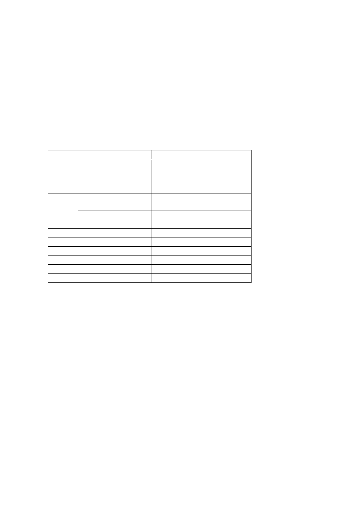
Model B-852-TS12-QQ/QP
Flash ROM 2 MB × 2 = 4 MB
Memory
SDRAM
Interface
Ribbon module Standard
Cutter module Option
PCL board Option
PCMCIA board Option
Keyboard (KB-80) Option
Expansion I/O interface board Option
Whole
Image buffer of
whole SDRAM
Standard
Option
8 MB × 1 = 8 MB
2.3 MB (640 mm long)
RS-232C
Centronics
TCP/IP
PCMCIA
- 1 -
Page 6
Available PCMCIA cards
• LAN card
SCCE589ET series only, manufactured by 3COM
• ATA card
ATA flash card using flash memory manufactured by SanDisk or HITACHI.
• Flash memory card
Capacity Operation Manufacturer Item Code
Device
Code
1 MB Read only Maxell EF-1M-TB AA D0H 1CH
Mitsubishi MF81M1-GBDAT01 D0H 1CH
4 MB Read/Write Maxell EF-4M-TB CC 88H B0H
Maxell EF-4M-TB DC ADH 04H
Read only Centennial
FL04M-15-11119-03 ADH 01H
Technologies INC.
INTEL IMC004FLSA A2H 89H
Simple TECNOLOGY STI-FL/4A A2H 89H
Mitsubishi MF84M1-G7DAT01 A2H 89H
PC Card KING MAX FJN-004M6C A2H 89H
Centennial
FL04M-20-11138-67 A2H 89H
Technologies INC.
PC Card FJP-004M6R A0H 89H
Mitsubishi MF84M1-GMCAV01 AAH 89H
Manufacturer’s
Code
- 2 -
Page 7

3. INTERFACE
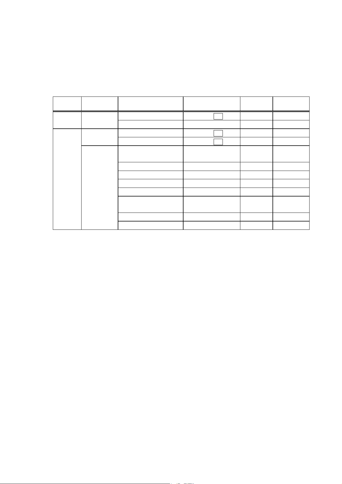
3.1 SERIAL INTERFACE
(1) Type: Conforming to RS-232C
(2) Mode of Communication: Full duplex
(3) Transmission Speed: 2400 bps
4800 bps
9600 bps
19200 bps
(4) Synchronization Method: Start-stop synchronization
(5) Start Bit: 1 bit
(6) Stop Bit: 1 bit
(7) Data Length: 7 bits
8 bits
(8) Parity: NONE
EVEN
ODD
(9) Error Detection: Parity Error Vertical parity error check
Framing Error This error occurs if no stop bit is found in the frame
specified starting with the start bit.
Overrun Error This error occurs if the next data is input before the
data input to the UART from the host is read.
(10) Protocol: No-procedure method
(11) Data Input Code: ASCII code
European character set 8 bit code
Graphics 8 bit code
(12) Receive Buffer: 10K bytes
- 3 -
Page 8

(13) Transmission Control: XON/XOFF (DC1/DC3) Protocol
READY/BUSY (DTR) Protocol
XON/XOFF (DC1/DC3) Protocol + READY/BUSY (DTR) Protocol
RTS Protocol
c XON/XOFF (DC1/DC3) Protocol
z When initialized after the power is turned on, this printer becomes ready to receive data and
sends an XON code (11H). (Transmission or non-transmission of the XON code is
selectable by means of the parameter setting.)
z The printer sends an XOFF code (13H) when the blank positions in the receive buffer are
800 bytes or less.
z The printer sends an XON code (11H) when the blank positions in the receive buffer are 2K
bytes or more.
z When there are no blank positions in the receive buffer, the printer discards data received
exceeding the receive buffer capacity, without storing it in the buffer. (After detecting the
XOFF code, the host computer must stop transmission before the printer receive buffer
becomes full.)
z The printer sends an XOFF code (13H) when the power is off. (Transmission or non-
transmission of the XOFF code is selectable by means of the parameter setting.)
z The DTR signal is always “High” (READY).
z The RTS signal is always “High”.
d READY/BUSY (DTR) Protocol
z When initialized after the power is turned on, this printer becomes ready to receive data and
turns the DTR signal to the “High” level (READY).
z The printer turns the DTR signal to the “Low” level (BUSY) when the blank positions in the
receive buffer are 800 bytes or less.
z The printer turns the DTR signal to the “High” level (READY) when the blank positions in
the receive buffer are 2K bytes or more.
z When there are no blank positions in the receive buffer, the printer discards data received
exceeding the receive buffer capacity, without storing it in the buffer. (After detecting the
BUSY signal, the host computer must stop transmission before the printer receive buffer
becomes full.)
z The RTS signal is always “High”.
- 4 -
Page 9

e XON/XOFF (DC1/DC3) Protocol + READY/BUSY (DTR) Protocol
z When initialized after the power is turned on, this printer becomes ready to receive data and
turns the DTR signal to the “High” level (READY). The printer also sends an XON code
(11H).
z When the blank positions in the receive buffer are 800 bytes or less, the printer turns the
DTR signal to the “Low” level (BUSY) and sends an XOFF code (13H).
z When the blank positions in the receive buffer are 2K bytes or more, the printer turns the
DTR signal to the “High” level (READY) and sends an XON code (11H).
z When there are no blank positions in the receive buffer, the printer discards data received
exceeding the receive buffer capacity, without storing it in the buffer. (After detecting the
XOFF code or BUSY signal, the host computer must stop transmission before the printer
receive buffer becomes full.)
z The printer sends an XOFF code (13H) when the power is off.
z The RTS signal is always “High”.
f RTS Protocol
z When initialized after the power is turned on, the printer turns the RTS signal to “High”
(READY).
z The printer turns the RTS signal to “Low” (BUSY) when the blank positions in the receive
buffer are 800 bytes or less.
z The printer turns the RTS signal to “High” (READY) when the blank positions in the receive
buffer are 2K bytes or more.
z When there are no blank positions in the receive buffer, the printer discards data received
exceeding the receive buffer capacity, without storing it in the buffer. (After detecting the
BUSY signal, the host computer must stop transmission before the printer receive buffer
becomes full.)
z The DTR signal is always “High” (READY).
- 5 -
Page 10
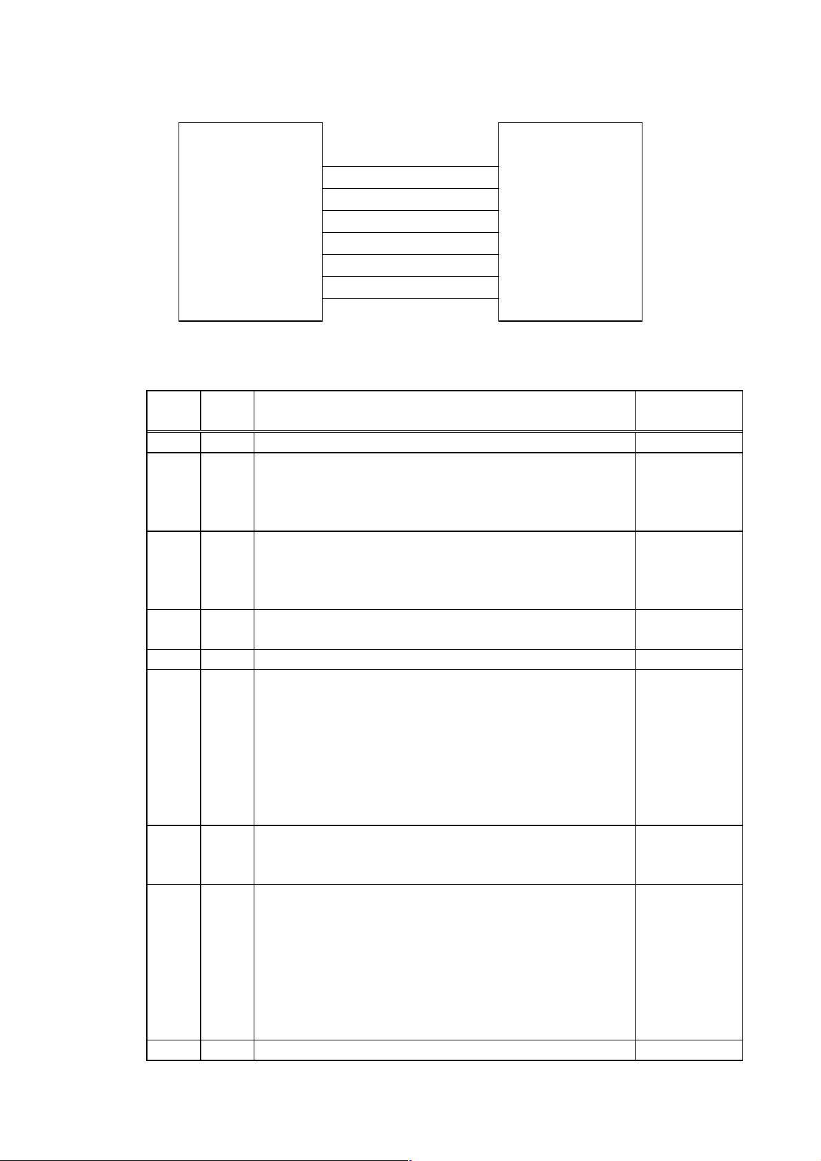
(14) Input/Output Signals
TD
RD
RTS
Printer Host
(15) Connector Pin Assignment and Signal Description
CTS
DSR
SG
DTR
Pin No.
Signal
Name
1 (N.C)
2TDz Line for data which the printer sends to the host
z Logic 1 is a Low level, while logic 0 is a High level.
z It is in the Low (Mark) state when no transmission is in
progress.
3RDz Line for data which the printer receives from the host
z Logic 1 is a Low level, while logic 0 is a High level.
z It is in the Low (Mark) state when no transmission is in
progress.
4 DSR z Input signal from the host
z For the printer to receive data, it must be at “High” level.
5SGz Ground line for all data and control signals
6 DTR z Output signal to the host
For the READY/BUSY (DTR) protocol or XON/XOFF
(DC1/DC3) protocol + READY/BUSY (DTR) protocol:
z It indicates the ready state for the received data.
z It is at the “Low” level when the receive buffer is near
full, and at the “High” level when near empty.
For the XON/XOFF (DC1/DC3) protocol or RTS protocol:
z After the power is turned on, it is always at “High”.
7 CTS z It is an input signal indicating whether or not the data
transmission to the host is possible. However, this printer
does not detect this signal.
8 RTS z Output signal to the host
For the RTS protocol:
z It indicates the ready state for the received data.
z It is at “Low” when the receive buffer is nearly full, and
at “High” when nearly empty.
For protocol other than the RTS protocol:
z After the power is turned on, it is always at the “High”
level.
9 (N.C)
Function Signal Direction
Printer →
← Host
← Host
Printer →
← Host
Printer →
- 6 -
Page 11
S
(16) Interface Circuit
z Input Circuit
RD
CTS
D
R
z Output Circuit
TD
RTS
DTR
z Signal Levels
Input Voltage H ......+3 ~ +15 V
SN75189 or equivalent
SN75188 or equivalent
L.......-3 ~ -15 V
Output Voltage H ......+6 ~ +13 V
L.......-6 ~ -13 V
- 7 -
Page 12

3.2 PARALLEL INTERFACE
NOTE: V1.0 does not support the nibble mode. The nibble mode will be supported in V1.1 or later.
(1) Type: Centronics
(2) Mode: Conforms to IEEE1284 compatible mode and nibble mode
(3) Data Input Method: Parallel 8 bits (Data 1 ~ 8)
(4) Control Signals: Compatible mode Nibble mode
nStrobe HostClk
nAck PtrClk
Busy PtrBusy
PError AckDataReq
Select Xflag
nAutoFd HostBusy
nInit nInit
nFault nDataAvail
nSelectIn IEEE1284 Active
(5) Data Input Code: ASCII code
European character set 8 bit code
Graphics 8 bit code
(6) Data Output Code in the Nibble Mode:
ASCII code (8 bits)
(7) Receive Buffer: 10K bytes
(8) Send Buffer in the Nibble Mode: 13 bytes
- 8 -
Page 13
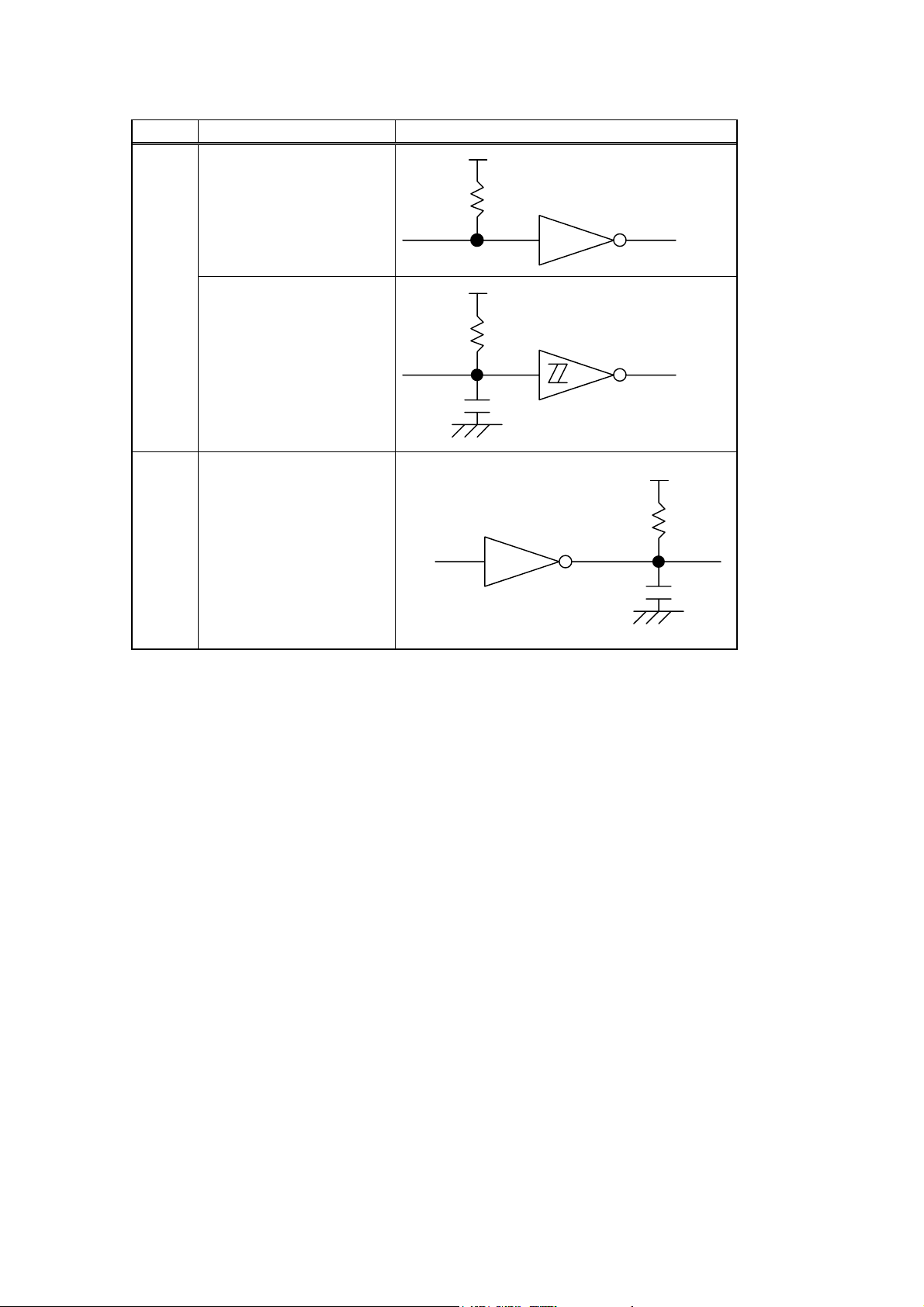
(9) Input/Output Circuit Configuration and Input/Output Conditions:
Signal Configuration
+5V
Input
Output
Data 1 ~ 8
nStrobe/HostClk
nInit/nInit
nAutoFd/HostBusy
nSelectIn/IEEE1284 Active
Busy/PtrBusy
nFault/nDataAvail
nAck/PtrClk
Select/Xflag
PError/AckDataReq
1K
+5V
1K
100P
SN7406 or equivalent
SN74LS245 or equivalent
SN74LS14 or equivalent
+5V
1K
100P
Logic level
(Input)
“1” = 2 ~ 5 V
“0” = 0 ~ 0.4 V
Logic level
(Input)
“1” = 2.4 ~ 5 V
“0” = 0 ~ 0.4 V
(10) Connector: Printer
Amp. Japan 552742-1 or equivalent
DDK 57RE-40360-73B or equivalent
Cable
Amp. Japan 552470-1 or equivalent
DDK 57E-30360 or equivalent
- 9 -
Page 14
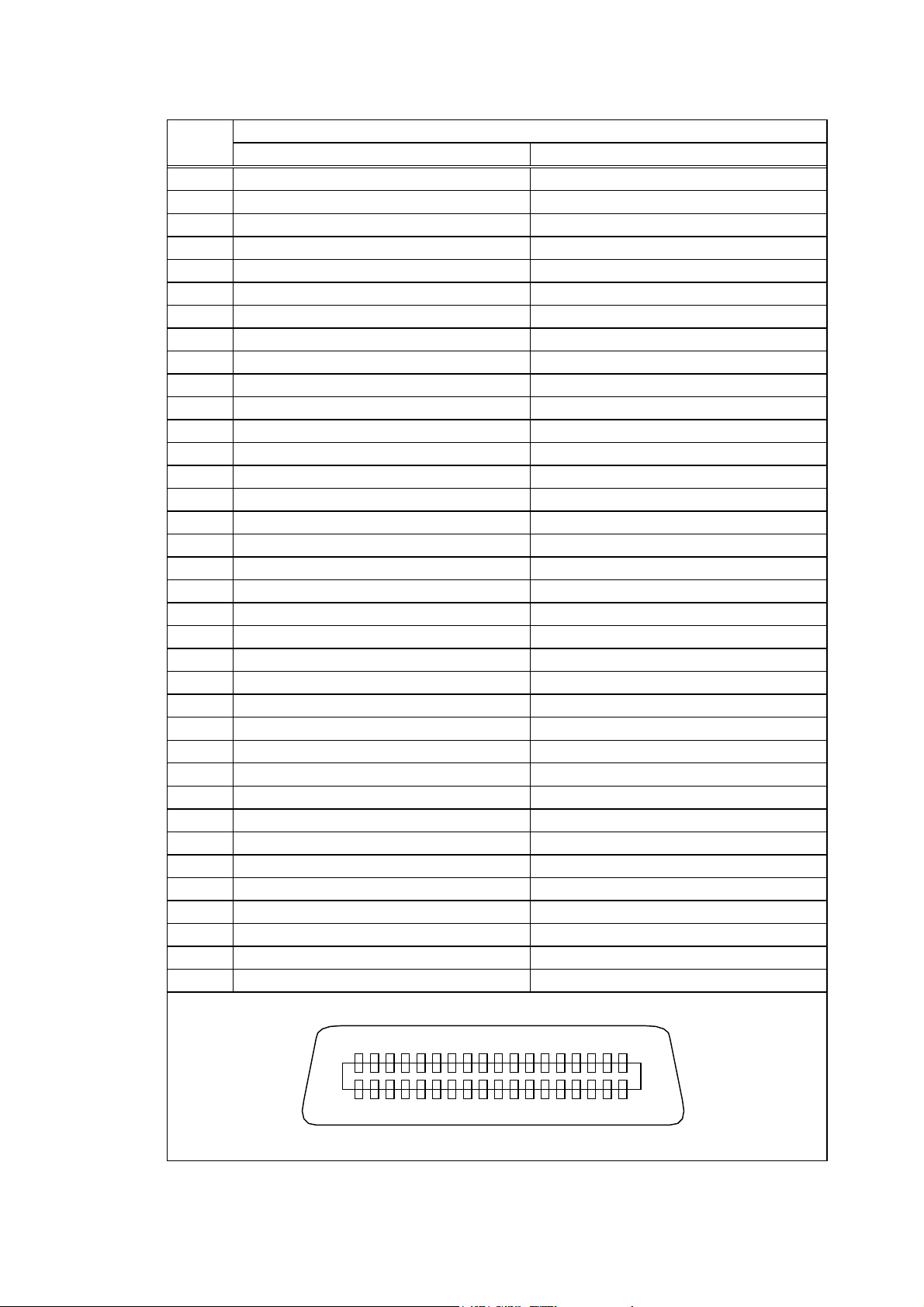
(11) Connector Pin Diagram (IEEE1284-B Connector):
Pin No. Signal Name
Compatible Mode Nibble Mode
1 nStrobe HostClk
2 Data 1 Data 1
3 Data 2 Data 2
4 Data 3 Data 3
5 Data 4 Data 4
6 Data 5 Data 5
7 Data 6 Data 6
8 Data 7 Data 7
9 Data 8 Data 8
10 nAck PtrClk
11 Busy PtrBusy
12 PError AckDataReq
13 Select Xflag
14 nAutoFd HostBusy
15 NC NC
16 0V 0V
17 CHASSIS GND CHASSIS GND
18 +5V +5V
19 TWISTED PAIR GND (PIN1) TWISTED PAIR GND (PIN1)
20 TWISTED PAIR GND (PIN2) TWISTED PAIR GND (PIN2)
21 TWISTED PAIR GND (PIN3) TWISTED PAIR GND (PIN3)
22 TWISTED PAIR GND (PIN4) TWISTED PAIR GND (PIN4)
23 TWISTED PAIR GND (PIN5) TWISTED PAIR GND (PIN5)
24 TWISTED PAIR GND (PIN6) TWISTED PAIR GND (PIN6)
25 TWISTED PAIR GND (PIN7) TWISTED PAIR GND (PIN7)
26 TWISTED PAIR GND (PIN8) TWISTED PAIR GND (PIN8)
27 TWISTED PAIR GND (PIN9) TWISTED PAIR GND (PIN9)
28 TWISTED PAIR GND (PIN10) TWISTED PAIR GND (PIN10)
29 TWISTED PAIR GND (PIN11) TWISTED PAIR GND (PIN11)
30 TWISTED PAIR GND (PIN31) TWISTED PAIR GND (PIN31)
31 nInit nInit
32 nFault nDataAvail
33 0V 0V
34 NC NC
35 NC NC
36 nSelectIn IEEE1284 Active
3619
181
NOTE: The signal name starting with a lower case “n” indicates that it is a low active signal.
- 10 -
Page 15

(12) Input/Output Signals:
Compatible mode
c Data 1 ~ 8 (Printer ← Host)
z Input data signals for the 1st to 8th bits
z Logic 1 is the “High” level.
z Min. data pulse width of 2.5 µsec
d nStrobe (Printer ← Host)
z Synchronizing signal for reading the above data
z Normally at the “High” level. The data is read at the rise of the Low level pulse.
z Minimum data pulse width of 0.5 µsec
e Busy (Printer → Host)
z This signal indicates that the printer is in a Busy state.
z When initialized after the power is turned on, the printer becomes ready to receive data and
turns the signal to the “Low” level.
z The signal turns to the “High” level (in a Busy state) when data is set from the host (at the
fall of the nStrobe signal).
z The signal turns to the “Low” level when the printer reads the data.
z When the blank positions in the receive buffer are 712 bytes or less, the printer keeps the
signal at the “High” level (in a Busy state) for 10 seconds when data is set from the host, to
extend the data read interval.
z When there are no blank positions in the receive buffer, the printer stops reading data.
Then, it keeps the signal at the “High” level (in a Busy state) until there are blank positions
in the receive buffer when data is set from the host.
z The signal is kept at the “High” level (in a Busy state) until the current state (one of the
following states) is reset.
• Pause state caused by the [PAUSE] key
• Paper end state
• Ribbon end state
• Head open state
• Printer error state
• Initialization in progress upon receipt of the nInit signal
f nAck (Printer → Host)
z This signal indicates that the printer has read the data set by the host and is ready to
receive the next data.
z One of 2 types of timing for Ack can be selected.
z One is normally at “High”. The Ack signal should be sent to match the fall of the Busy
signal and the end of the Low level of the Ack signal for about 0.7 µsec. The host should
usually set data after the Ack signal is turned from “Low” to “High”, or after the fall of the
Busy signal. (Default timing)
z The other is normally at “High”. It is at “Low” for about 5 µsec. after the fall of the Busy
signal. The host should usually set data after the Ack signal is turned from “Low” to “High”.
- 11 -
Page 16

g nInit (Printer ← Host)
z Reset request signal from the host
z Normally at the “High” level. A low on this input causes the printer to be initialized in the
same manner as when the power is turned on.
z When the nInit signal is input during printing, the printer completes printing one label which
is being printed, cancels the next processing, then is initialized in the same manner as
when the power is turned on.
z Minimum pulse width of 0.5 µsec
h Select (Printer → Host)
z This is an output signal which indicates whether the printer is in a Pause state or placed
online. The printer can receive data while placed online.
z The signal is at the “Low” level while the printer is in a Pause state.
z The signal is kept at the “Low” level (in a Pause state) until the current state (one of the
following states) is reset.
• Pause state caused by the [PAUSE] key
• Paper end state
• Ribbon end state
• Head open state
• Printer error state
• Initialization in progress upon power on or receipt of the nInit signal
i nFault (Printer → Host)
z Output signal indicating that the printer is in a Fault state
z At the “Low” level while the printer is in a Fault state.
z The signal is kept at the “Low” level (in a Fault state) until the current state (one of the
following states) is reset.
• Pause state caused by the [PAUSE] key
• Paper end state
• Ribbon end state
• Head open state
• Printer error state
• Initialization in progress upon power on or receipt of the nInit signal
j PError (Printer → Host)
z Output signal indicating a label end state or ribbon end state.
z At the “High” level when the printer is in a label end state or ribbon end state.
z Turns to the “Low” level when the label end state or ribbon end state is reset.
k +5 V
z This is not a signal but a +5 V power supply voltage.
z The maximum current of 500 mA can be taken out.
l nSelectIn (Printer ← Host)
z Not used
11
nAutoFd (Printer ← Host)
z Not used
- 12 -
Page 17

Nibble mode
c Data 1 ~ 8 (Printer ← Host)
z Input data signals for the 1st to 8th bits
z Logic 1 is the “High” level.
z Minimum data pulse width of 2.5 µsec
d HoltClk (Printer ← Host)
z Synchronizing signal for reading the above data
z Normally at the “High” level. The data is read at the rise of the Low level pulse.
z Minimum data pulse width of 0.5 µsec
e PtrBusy (Printer → Host)
z Reverse data transfer phase: Data bit 3 is used for the first transfer. Data bit 7 is used for
the second transfer. Indicates the forward channel is in a
Busy state.
f PtrClk (Printer → Host)
z Reverse data transfer phase: It is used for evaluating data sent to the host.
z Forward idle phase: When the printer changes the signal from Low to High, an interrupt
informing the host that the data is available, occurs.
g nInit (Printer ← Host)
z Reset request signal from the host.
z Normally at the “High” level. When the signal becomes low, the printer enters an initial
state obtained from when the power is turned ON.
z If the “nInit” signal is input during printing, the printer cancels the next process after printing
one label which is being printed, then enters an initial state obtained from when the power is
turned ON.
z Minimum pulse width of 0.5 µsec
h Xflag (Printer → Host)
z Reverse data transfer phase: Data bit 1 is used for the first transfer. Data bit 5 is used for
the second transfer.
i nDataAvail (Printer → Host)
z Reverse data transfer phase: When the signal is low, it indicates the printer has data to be
sent to the host. And it is used for sending data bits 0 and 4.
z Reverse idle phase: It is used for indicating that the data is available.
j AckDataReq (Printer → Host)
z Reverse data transfer phase: Data bit 2 is used for the first transfer. Data bit 6 is used for
the second transfer.
z Reverse idle phase: This signal is set to high until data transfer is requested by the host.
After that, the process is performed according to the nDataAvail signal.
- 13 -
Page 18

k +5 V
z This is not a signal but a +5 V power supply voltage.
z The maximum current of 500 mA can be used for external equipement.
l IEEE1284 Active (Printer ← Host)
z The signal is used with the HostBusy signal, to request the data transfer in the IEEE1284
mode, or to request the end of the IEEE1284 mode.
z To request the data transfer in the IEEE1284 mode, the host sets the IEEE1284 Active
signal and the HostBusy signal to high and low, respectively.
z To request the end of the IEEE1284 mode, the host sets the IEEE1284 Active signal and
the HostBusy signal to low and high, respectively.
11
HostBusy (Printer ← Host)
z Reverse data transfer phase: It indicates that the host can receive data from the printer by
setting the signal to low. After that, the host sets the signal
to high, and sends the Ack indicating that the nibble data is
received. When the signal is set to low after the reverse
channel data transfer is performed, the interface phase
changes to the idle phase. At that time, there is no available
data on the printer.
z Reverse idle phase: W hen this signal is set to high according to the low pulse of the
PtrClk signal, the host enters the reverse data transfer phase again.
If this signal is set to high when the IEEE1284 Active signal is low,
the IEEE1284 idle phase stops, and the interface enters the
compatible mode.
- 14 -
Page 19
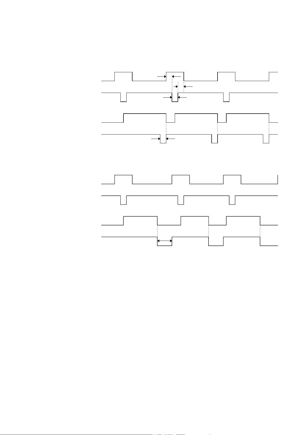
(13) Timing Chart
c When receiving normal data:
One of two types of timing for BUSY-ACK can be selected.
(1) Timing 1 (Default)
Data 1 ~ 8
(Host → Printer)
nStrobe
(Host → Printer)
Busy
(Host ← Printer)
nAck
(Host ← Printer)
(2) Timing 2
Data 1 ~ 8
(Host → Printer)
nStrobe
(Host → Printer)
Busy
(Host ← Printer)
Min. 1 µsec
Min. 1 µsec
Min. 1 µsec
Min. 0.5 µsec
Approx. 0.7 µsec
nAck
(Host ← Printer)
Approx. 5 µsec
- 15 -
Page 20
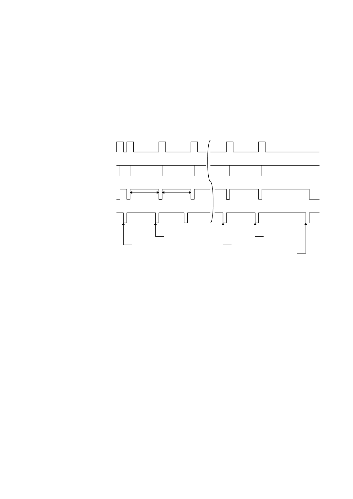
d Receiving data when the blank positions in the receive buffer are 712 bytes or less:
z When the blank positions in the receive buffer are 712 bytes or less, the printer stores the
received data in the receive buffer, continues to be in a BUSY state (BUSY signal at the
“High” level) for 10 seconds to extend the data read interval when data is set from the host,
and reads the data 10 seconds later.
z If the blank positions become 713 bytes or more while waiting for reading data, the printer
will receive the data with the normal data receive timing.
z When there are no blank positions in the receive buffer, the printer stops reading data.
Then, it continues to be in a BUSY state (BUSY signal at the “High” level) until there are
blank positions in the receive buffer when data is set from the host.
Data 1 ~ 8
(Host → Printer)
nStrobe
(Host → Printer)
Busy
(Host ← Printer)
nAck
(Host ← Printer)
10 sec
10 sec
511 to 711 blank bytes 0 blank byte
1 blank byte712 blank bytes
1 blank byte
- 16 -
Page 21
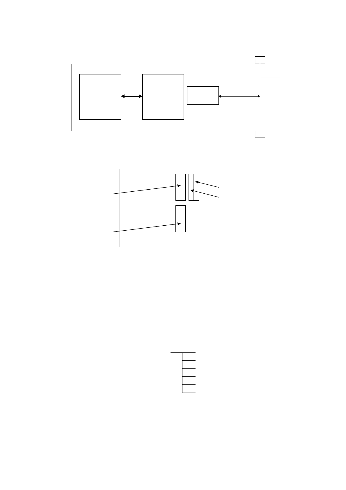
3.3 NETWORK INTERFACE
(1) Connection Diagram
CPU
board
Printer
PCMCIA
board
LAN card
TCP/IP
There are two slots (slot 1 and slot 2) for the PC card on the PCMCIA board. The LAN card
should be inserted in slot 2. If it is inserted in slot 1, it will not function.
Centronics
RS-232C
Backside of printer
Slot 1
Slot 2
(The LAN card should be inserted here.)
(2) Applicable LAN Card: LAN PC Card manufactured by 3COM
Model: 3CCE589ET series
(3) Protocol: TCP/IP
(4) Items for Settings: Printer IP address (Initial value: 192.168.10.20)
Subnet mask (Initial value: 0xffffff00)
Gateway IP address (Initial value: 0.0.0.0)
(5) Printer Daemon: This printer starts up as a LPR server.
(6) HTTP Server: This printer can be used for the Internet as an HTTP server to browse
a home page for following information.
TOP menu Status (Idling/Error)
Remaining length of ribbon
Head up/down state
Label sensor state
Temperature sensor state
Maintenance counter
(7) Socket communication: This printer can make socket communications using the specified
port number.
(8) Mail transmission/reception: This printer can send/receive commands, and notify the host of the
printer status by e-mail.
(9) FTP server function: This printer can be operated remotely with a FTP client.
* For details, refer to the Network Specification (TAA-1323).
- 17 -
Page 22

4. KEY OPERATION FUNCTIONS
4.1 SYSTEM MODE FUNCTIONS
The system mode has the following functions for the printer self-test and various parameters settings.
(For details, refer to Key Operation Specification.)
(1) Self-test
• Maintenance counter, various parameters printout
• Automatic self-test
• Head broken dots check
(2) Various parameter settings
• Type of character code
• PC-850
• PC-852
• PC-857
• PC-8
• PC-851
• PC-855
• PC-1250
• PC-1251
• PC-1252
• PC-1253
• PC-1254
• PC-1257
• LATIN9
• Arabic
• Selection of font 0
• without slash mark [0]
• with slash mark [0]
• RS-232C communication speed
• 2400 bps
• 4800 bps
• 9600 bps
• 19200 bps
• RS-232C data length
• 7 bits
• 8 bits
• RS-232C parity
• NONE
• EVEN
• ODD
- 18 -
Page 23

• RS-232C transmission control
• XON/XOFF protocol: (No XON output when the power is on, no XOFF
output when the power is off)
• READY/BUSY (DTR) protocol: (No XON output when the power is on, no XOFF
output when the power is off)
• XON/XOFF + READY/BUSY (DTR) protocol:
(XON output when the power is on, XOFF output
when the power is off)
• XON/XOFF protocol: (XON output when the power is on, XOFF output
when the power is off)
• RTS protocol: (No XON output when the power is on, no XOFF
output when the power is off)
• Language for LCD messages
• ENGLISH
• GERMAN
• FRENCH
• DUTCH
• SPANISH
• JAPANESE
• ITALIAN
NOTE: When Japanese is selected, the character cords partially differ.
• Forward feed standby after an issue
• ON (Performed)
• OFF (Not performed)
NOTE: If the printer is in the idle state for 1 second or more after an issue is performed when
ON is selected, the printer automatically performs a 19-mm forward feed, then stops.
This setting is used to prevent curled labels from being entangled with the cutter or the
platen, or to cut labels manually.
• Type of control code
• Automatic selection (ESC, LF, NUL/{, |, })
• Manual selection (ESC, LF, NUL mode)
• Manual selection ( {, |, } mode)
• Any set code
• [FEED] key function
• FEED: Feeds one label.
• PRINT: Prints data of image buffer on one label.
• Kanji code selection
• TYPE1
• TYPE2
• Euro code (new currency symbol) setting
• 20H to FFH
• Automatic head broken dots check
• ON (When the power is turned on, the broken dots check is automatically performed.)
• OFF (When the power is turned on, the broken dots check is not automatically performed.)
- 19 -
Page 24

• Centronics ACK/BUSY timing setting
• TYPE1
• TYPE2
• Web printer function setting
• ON (Web printer function is enabled.)
• OFF (Web printer function is disabled.)
• Silent printing function setting
• ON (Silent printing function is enabled.)
• Keyboard (KB-80) connection setting
• ON (The keyboard is connected.)
• OFF (The keyboard is not connected.)
(3) Various fine adjustment value settings
• Feed fine adjustment (± 50.0 mm)
• Cut position (or stop position of the strip issue) fine adjustment (± 50.0 mm)
• Back feed fine adjustment (± 9.5 mm)
• X-coordinate fine adjustment (± 99.5 mm)
• Print density fine adjustment
(Thermal transfer/Direct thermal print modes) (± 10)
• Lower reflective sensor manual threshold fine adjustment (0.0 V to 4.0 V)
• Transmissive sensor manual threshold fine adjustment (0.0 V to 4.0 V)
• Ribbon motor drive voltage fine adjustment (Rewind) (-15 to +6)
• Ribbon motor drive voltage fine adjustment (Back tension) (-15 to +10)
(4) Test print
(5) Sensor display/adjustment
• Thermal head temperature sensor display
• Open-air temperature sensor display
• Heat sink sensor display
• Upper reflective sensor display/adjustment
• Lower reflective sensor display/adjustment
• Transmissive sensor display/adjustment
• Lower reflective sensor adjustment value setting (without paper)
• Transmissive sensor adjustment value setting (without paper)
(6) RAM clear
• Maintenance counter clear
• Parameter clear
(7) IP address setting
• Printer IP address
• Gateway IP address
• Subnet mask
- 20 -
Page 25
(8) PCL emulation setting
• PCL emulation ON/OFF
• Print speed
• Sensor type
• Print type
• Issue type
• Media setting
(9) BASIC interpreter setting
• BASIC interpreter ON/OFF
• Trace function ON/OFF
(10) Initial values after RAM clear
• Initial values after maintenance counter clear
Parameter Initial Value
Label distance covered 0 km
Printed distance 0 km
Cut count 0
Ribbon motor drive time 0 hour
RS-232C hardware error count 0
System error count 0
Momentary power interruption count 0
‚ Initial values after parameter clear
Parameter Initial Value
Feed fine adjustment (PC) 0 mm
Cut position (or stop position of the strip issue) fine
0 mm
adjustment (PC)
Back feed fine adjustment (PC) 0 mm
Print density fine adjustment
0
(Thermal transfer print mode) (PC)
Print density fine adjustment
0
(Direct thermal print mode) (PC)
Ribbon motor drive voltage fine adjustment (Rewind)
0
(PC)
Ribbon motor drive voltage fine adjustment
0
(Back tension) (PC)
Feed fine adjustment (Key) 0 mm
Cut position (or stop position of the strip issue) fine
0 mm
adjustment (Key)
Back feed fine adjustment (Key) 0 mm
Print density fine adjustment
0
(Thermal transfer print mode) (Key)
Print density fine adjustment
0
(Direct thermal print mode) (Key)
Ribbon motor drive voltage fine adjustment (Rewind)
0
(Key)
Ribbon motor drive voltage fine adjustment
0
(Back tension) (Key)
X-coordinate fine adjustment (Key) 0 mm
- 21 -
Page 26
Parameter Initial Value
Transmissive sensor manual threshold fine
adjustment value
Reflective sensor manual threshold fine adjustment
value
Type of character code PC-850
Font of 0 “0” (without slash mark)
Type of control code Auto
Communication speed 9600 bps
Data length QP type 8 bits
QQ type 7 bits
Parity QP type NONE
QQ type EVEN
Transmission control QP type XON/XOFF + READY/BUSY
(DTR) protocol:
(XON output when the power
is on, XOFF output when the
power is off)
QQ type READY/BUSY (DTR)
Language for LCD messages QP type English
QQ type English
Forward feed standby after an issue ON
Automatic head broken dots check OFF
[FEED] key function FEED
Status response ON
Label pitch 76.2 mm
Effective print length 74.2 mm
Effective print width 216.8 mm
Print type Thermal transfer print mode
Type of sensor Transmissive sensor
Feed speed 4”/sec
Issue mode Batch (without cutting)
PC save automatic call ON
Kanji code TYPE1
Euro code B0H
Centronics ACK/BUSY timing setting
Web printer function OFF
Silent printing function QP type ON
QQ type ON
PCL emulation OFF
Keyboard (KB-80) connection setting OFF
BASIC interpreter function OFF
BASIC trace function OFF
1.4 V
1.0 V
protocol
TYPE1
• The total label distance covered, sensor adjustment values (system mode <5>), IP address
setting and data of the flash memory card, are not cleared by RAM clear.
- 22 -
Page 27

4.2 ONLINE MODE FUNCTIONS
The online mode provides the following functions for issuing labels and setting the threshold.
(For details, refer to Key Operation Specification.)
(1) Issuing labels (by external equipment interface commands)
(2) Paper feed (by the [FEED] key)
(3) Pause (Halts issuing labels by the [PAUSE] key)
(4) Restart (Reissues labels by the [RESTART] key after halting issuing labels or after the occurrence
of an error.)
(5) Reset (Enters an usual initial state which is obtained after the power is turned on, using the
[RESTART] key.)
(6) Error indication
(7) Threshold setting
(8) Various parameters setting
(9) Various fine adjustment value settings
4.3 DOWNLOAD MODE SETTING FUNCTION
When the power is turned on by pressing the [FEED], [PAUSE], and [RESTART] keys at the same
time, the printer enters the download mode. Therefore, the usual operations cannot be performed.
- 23 -
Page 28
5. TRANSMISSION SEQUENCE
This section describes the outline of the transmission sequence.
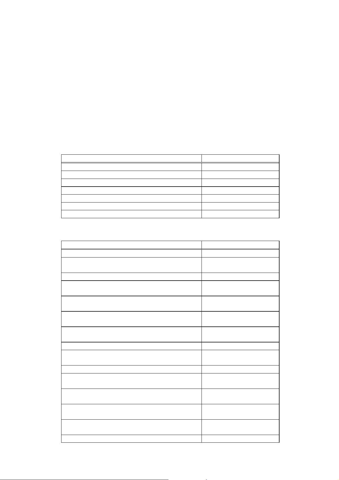
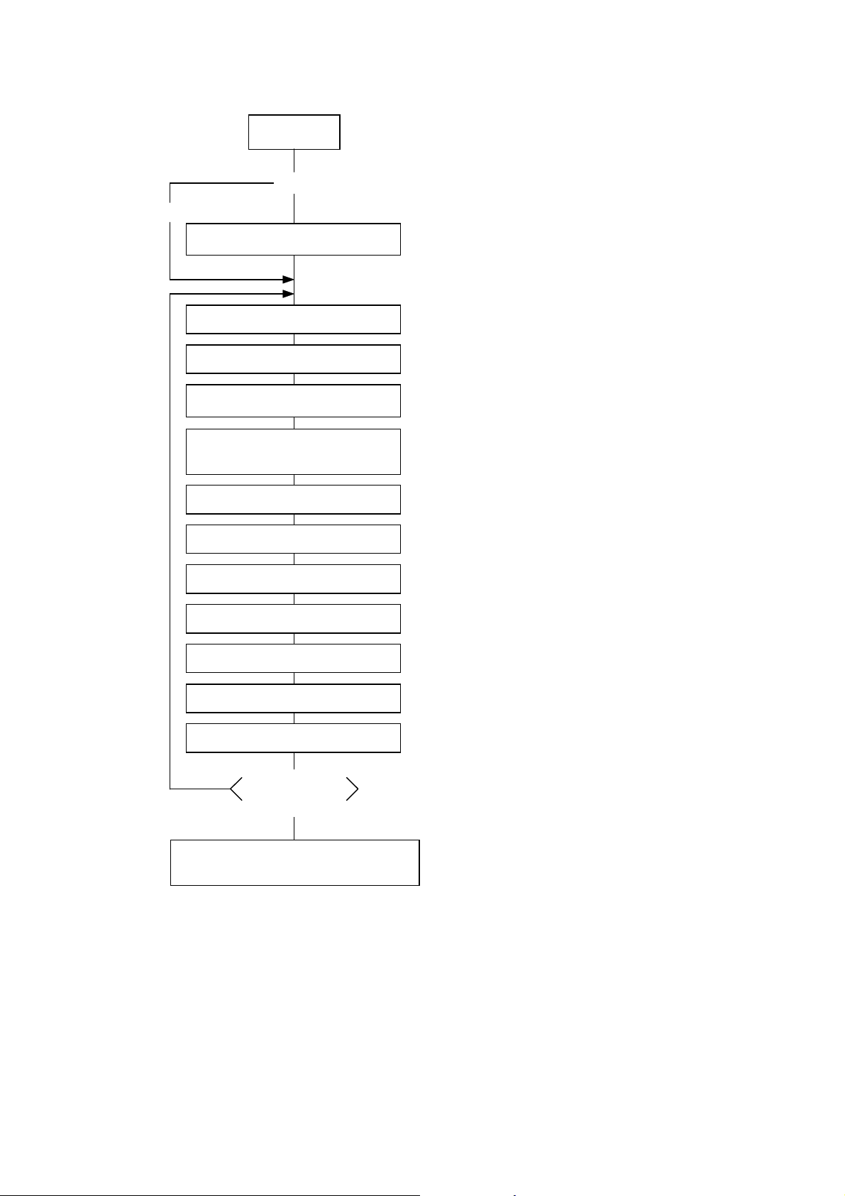
5.1 INITIALIZATION
Writable characters, logos, and PC interface commands must be stored before the label issue
operation.
(1) Storing writable characters and logos
Power ON
No
<New>
(Add/change)
Memory Card
Format Command
Yes
[ESC] J1: Formats the 4-MB flash memory
card (manufactured by Maxell).
or
[ESC] JA: Formats the ATA card.
[ESC] XD: Stores writable characters or
Bit Map Writable
Character Command
[ESC] XA: Stores writable characters or
No
Completion of storing
all characters
Yes
z Storing PC interface commands
z Label issue operation
NOTES: (1) The storage of PC commands is only performed if it is required.
(2) When the flash memory card is used, and the Memory Card Format Command is not
sent before storing already stored writable characters or logos, memory will be taken up
with every such storing.
(3) When the flash memory card is used, and another operation (storing PC interface
commands or label issue operation) is performed after storing writable characters or
logos, the image buffer will be cleared automatically.
(4) If another storing operation does not take place after storing writable characters or
logos, the printer automatically enters the online mode (label issue operation) after
about 10 seconds. In this case, when the flash memory card is used, the image buffer
will be automatically cleared.
logos on the flash memory card.
logos on the ATA card.
- 24 -
Page 29
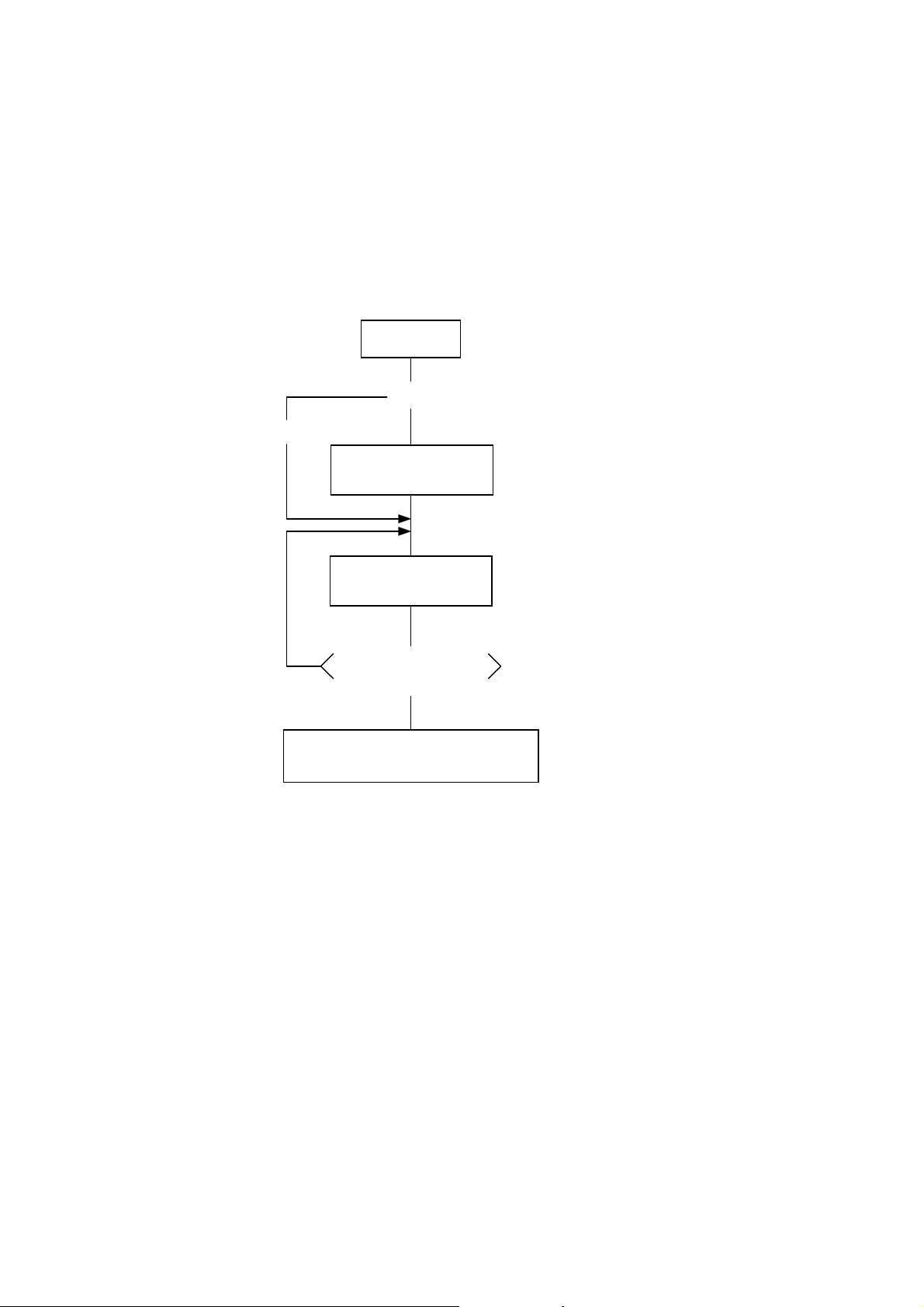
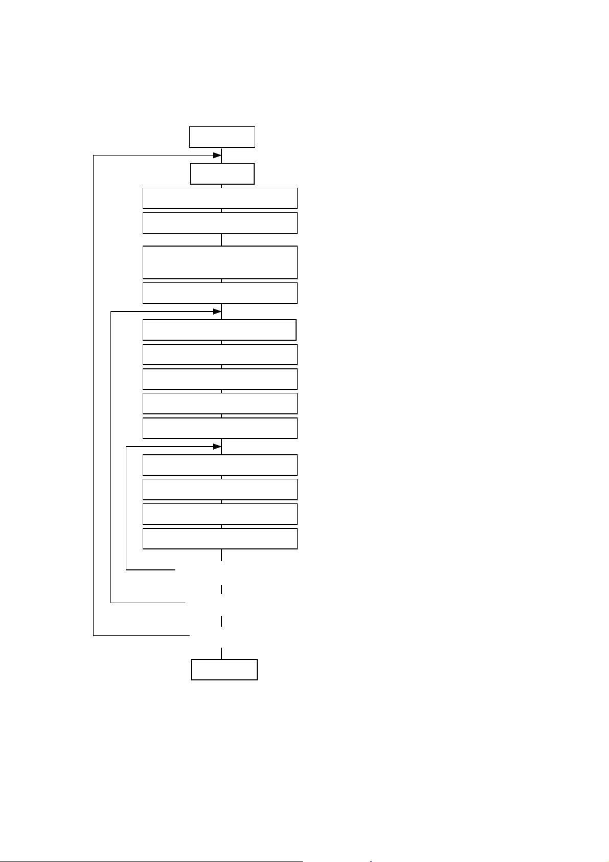
(2) Storing PC interface commands
p
Power ON
No
<New>
(Add/change)
Memory Card Format Command
Position Fine Adjust Command
Bit Map Font Format Command
Outline Font Format Command
Yes
Save Start Command
Label Size Set Command
Print Density Fine
Adjust Command
Image Buffer Clear Command
Line Format Command
[ESC] J1: Formats the flash memory card.
or
[ESC] JA: Formats the ATA card.
[ESC] XO, [ESC] XV: Declares the start of saving
PC interface commands.
[ESC] D: Sets the label size.
[ESC] AX: Adjusts the feed length, cut position,
and back feed length.
[ESC] AY: Adjusts the print density.
[ESC] C: Clears the image buffer.
[ESC] LC: Sets the line format and draws it.
[ESC] PC: Sets the bit map font format.
[ESC] PV: Sets the outline font format.
Bar Code Format Command
Bit Map Font Data Command
Save Terminate Command
No
z Storing writable characters or logos
z Label issue o
NOTES: (1) The storage of PC interface commands is only performed if it is required.
(2) When the flash memory card is used, and the Memory Card Format Command is not sent
before storing already stored PC interface commands, memory will be taken up with every
such storing.
(3) When the flash memory card is used, and another operation (storing writable characters
or logos, label issue operation) is performed after storing PC interface commands, the
image buffer will be cleared automatically.
(4) Select commands to be stored as the occasion demands.
(5) If another storing operation does not take place after storing PC interface commands, the
printer enters the online mode (label issue operation) after about 10 seconds. In this
case, when the flash memory card is used, the image buffer will be automatically cleared.
Completion of
all storing
Yes
eration
[ESC] XB: Sets the bar code format.
[ESC] RC: Draws data of the bit map font.
[ESC] XP: Declares the termination of saving PC
interface commands.
- 25 -
Page 30
5.2 LABEL ISSUE OPERATION
j
An example of the label issue operation is described below.
(1) Where the Saved Data Call Command is not used:
Power ON
Place paper
Label Size Set Command
Position Fine Adjust Command
Print Density Fine
Ad
ust Command
Feed Command
Image Buffer Clear Command
Line Format Command
Bit Map Font Format Command
Outline Font Format Command
Bar Code Format Command
Bit Map Font Data Command
Outline Font Data Command
[ESC] D: Sets the label size.
[ESC] AX: Adjusts the feed length, cut position,
and back feed length.
[ESC] AY: Adjusts the print density.
[ESC] T: Feeds one sheet of paper and aligns
it with the first printing position.
[ESC] C: Clears the image buffer.
[ESC] LC: Sets the line format and draws it.
[ESC] PC: Sets the bit map font format.
[ESC] PV: Sets the outline font format.
[ESC] XB: Sets the bar code format.
[ESC] RC: Draws bit map font data.
[ESC] RV: Draws outline font data.
Bar Code Data Command
Issue Command
Yes
<Changed data issue>
Yes
<Format change>
Yes
<Label change>
Power OFF
NOTES: (1) When placing new paper, the Label Size Set Command and Feed Command must
always be sent. When using the same paper after the power is turned off and on, the
Label Size Set Command and Feed Command may be omitted.
(2) After the power is turned off and on, the Bit Map Font Format Command, the Outline
Font Format Command, and the Bar Code Format Command should be sent as
occasion demands because they are not protected in memory.
No
No
No
[ESC] RB: Draws bar code data.
[ESC] XS: Issues (prints) the label.
- 26 -
Page 31

(2) Where the Saved Data Call Command is used:
Power ON
Place paper
Saved Data Call Command
Feed Command
Bit Map Font Data Command
Outline Font Data Command
Bar Code Data Command
Issue Command
Yes
<Changed data issue>
Yes
<Label change>
No
No
[ESC] XQ: Calls the label format stored in the
flash memory card.
or
[ESC] XT: Calls the label format stored in the
ATA card.
[ESC] T: Feeds one sheet of paper and aligns
it with the first printing position.
[ESC] RC: Draws bit map font data.
[ESC] RV: Draws outline font data.
[ESC] RB: Draws bar code data.
[ESC] XS: Issues (prints) the label.
Power OFF
NOTES: (1) When placing new paper, the Feed Command must always be sent. When using the
same paper after the power is turned off and on, the Feed Command may be omitted.
(2) If the option for “automatic call at power on” for the Saved Data Call Command has
previously been selected, the Saved Data Call Command may be omitted after the
power is turned off and on.
(3) When the XML data is used:
Print data in XML format can be sent to the printer.
* For details, refer to the XML Data Print Specification (TAA-1320).
- 27 -
Page 32

6. INTERFACE COMMANDS
6.1 OUTLINE OF COMMANDS
(1) Format of Interface command
ESC Command & Data LF NUL
z The length from [ESC] to [LF] [NUL] must be as specified by each command.
z There are the following three kinds of control codes:
c ESC (1BH), LF (0AH), NUL (00H)
d { (7BH), | (7CH), } (7DH)
e Code set in the system mode
(2) How to use reference
Function Describes the outline of the function of the command.
Format Shows the format of the command.
The format designation method should conform to the following rules:
z Each set of small letters (such as aa, bbbb) indicates a parameter item.
z An item enclosed in parentheses may be omitted.
z “…” indicates the repetition of an item.
z Brackets and parentheses are used only in coding, and must not be transmitted
in practice.
z Other symbols must always be inserted at the designated positions before being
transmitted.
Term Explains the term(s) used in the format.
* “0 to 999” described in the entry range indicates that up to 3-digit variable-length
entry is allowed. (Entry of “001” or “009” is also possible.) “000 to 999” indicates
that entry must be fixed as 3 digits.
Explanation Explains the command in detail.
Note Supplementary explanation of the command.
Refer to Related commands
Examples Explains the command examples.
[ESC] T20C40 [LF] [NUL]
The above corresponds to the transfer of the following:
1B 54 3030 43 3432 0A 00
[ESC]
(3) Precautions
The commands and parameters described in this specification must always be used. If any
command or parameter other than those covered in this specification is used, the printer’s
operation will not be guaranteed. The commands must be used in the online mode. If any
command is transmitted in the system mode, the printer will not operate. However, only the
Reset Command can be used.
T 2 0 C 4 0 [LF] [NUL]
- 28 -
Page 33

6.2 LIST OF COMMANDS
6.2.1 Commands for Creating Application
(1) Commands related to setting
Label Size Set Command [ESC] D
(2) Commands related to fine adjustment
Position Fine Adjust Command [ESC] AX
Print Density Fine Adjust Command [ESC] AY
Ribbon Motor Drive Voltage Fine Adjust Command [ESC] RM
(3) Commands related to clear
Image Buffer Clear Command [ESC] C
Clear Area Command [ESC] XR
(4) Commands related to drawing format setting
Line Format Command [ESC] LC
Bit Map Font Format Command [ESC] PC
Outline Font Format Command [ESC] PV
Bar Code Format Command [ESC] XB
(5) Commands related to print data
Bit Map Font Data Command [ESC] RC
Outline Font Data Command [ESC] RV
Bar Code Data Command [ESC] RB
(6) Commands related to issue and feed
Issue Command [ESC] XS
Feed Command [ESC] T
Eject Command [ESC] IB
Forward/Reverse Feed Command [ESC] U1, [ESC] U2
(7) Commands related to writable characters
Storage Area Allocate Command [ESC] XF
Memory Card Format Command (for flash memory card) [ESC] J1
Memory Card Format Command (for ATA card) [ESC] JA
2-byte Writable Character Code Range Command [ESC] XE
Bit Map Writable Character Command (for flash memory card) [ESC] XD
Bit Map Writable Character Command (for ATA card) [ESC] XA
(8) Commands related to graphics
Graphic Command [ESC] SG
(9) Commands related to PC command saving
Memory Card Format Command (for flash memory card) [ESC] J1
Memory Card Format Command (for ATA card) [ESC] JA
Save Start Command (for flash memory card) [ESC] XO
Save Start Command (for ATA card) [ESC] XV
Save Terminate Command [ESC] XP
Saved Data Call Command (for flash memory card) [ESC] XQ
Saved Data Call Command (for ATA card) [ESC] XT
(10) Commands related to check
Head Broken Dots Check Command [ESC] HD
- 29 -
Page 34

(11) Commands related to display
Message Display Command [ESC] XJ
(12) Commands related to control
Reset Command [ESC] WR
(13) Commands related to status
Status Request Command [ESC] WS
Version Information Acquire Command [ESC] WV
ATA Card Information Acquire Command [ESC] WI
ATA Card Writable Character Information Acquire Command [ESC] WG
(14) Commands related to TCP/IP setting
IP Address Set Command [ESC] IP
Socket Communication Port Set Command [ESC] IS
6.2.2 Commands for System Administrator
Parameter Set Command [ESC] Z2; 1
Fine Adjustment Value Set Command [ESC] Z2; 2
Batch Reset Command [ESC] Z0
- 30 -
Page 35

6.3 COMMANDS FOR CREATING APPLICATION
6.3.1 Label Size Set Command [ESC] D
Function Sets the size of a label or tag.
Format [ESC] Daaaa, bbbb, cccc [LF] [NUL]
Term aaaa: Pitch length of the label or tag
4 or 5 digits (in 0.1 mm units)
4 digits: Max. 9990 (999.0 mm)
5 digits: Max. 09990 (999.0 mm)
bbbb: Effective print width
Fixed as 4 digits (in 0.1 mm units)
cccc: Effective print length
4 or 5 digits (in 0.1 mm units)
4 digits: Max. 6400 (640.0 mm)
5 digits: Max. 06400 (640.0 mm)
Explanation
[Labels]
Backing paper width
Backing paper width
Origin of
coordinates
(0, 0)
Effective
print length
0
Y
X
Effective
print width
Paper feed direction
[Print direction: Printing bottom first]
Backing paper
Label
Label
pitch
Effective
print length
X
Label
pitch
Origin of
Y
0
Effective
print width
Paper feed direction
coordinates
[Printing direction: Printing top first]
Backing paper
Label
(0, 0)
- 31 -
Page 36

p
p
[Tags]
Black mark
Black mark
Origin of
coordinates
(0, 0)
Effective
print length
0
Y
[Print direction: Printing bottom first]
[Setting range]
Stop
osition
Cut
position
Tag
Tag
pitch
X
Effective
print width
Paper feed direction
Effective
print length
X
Y
0
Effective
print width
Paper feed direction
Tag
Tag
pitch
Origin of
coordinates
(0, 0)
[Printing direction: Printing top first]
Black mark
I
E
Stop
position
Cut
osition
I
Tag
F
Origin c
H
Origin d
G
D
C
A
B
Paper feed direction
H
Origin c
A
Origin d
G
C
[Labels] [Tags]
- 32 -
Page 37

Model B-850
Strip issue for
auto labeler
Item
Method Batch issue Cut issue
Thermal head dot density 11.8 dots/mm
Thermal head width 216.8 mm
A: Label pitch Label Min. 15.0 38.0 25.4
Tag pitch Max. 999.0 999.0 999.0
Tag Min. 15.0 25.4 –
Max. 999.0 999.0 –
B: Label length Min. 13.0 25.0
*2
23.4
Max. 997.0 993.0 997.0
C: Backing paper width Min. 100.0 100.0 100.0
Tag width Max. 242.0 235.0 242.0
D: Label width Min. 97.0 97.0 97.0
Max. 239.0 232.0 239.0
E: Label-to-label gap Min. 2.5 6.0 2.5
Max. 20.0 20.0 20.0
F: Black mark length Min. 2.0 2.0 2.0
Max. 10.0 10.0 10.0
G: Effective print width Min. 10.0 10.0 10.0
Max. 216.8 216.8 216.8
H: Label Min. 11.0 23.0 21.4
Effective print Max. 640.0 640.0 640.0
length Tag Min. 13.0 23.4 23.4
Max. 640.0 640.0 640.0
I: Slow up/down Slow up 1.0 1.0 1.0
interval Slow down 1.0 1.0 1.0
Max. effective print length for on-the-fly
320.0 320.0 320.0
issue
[mm]
*1
“1: To perform the strip issue for the auto labeler, the backing paper rewind system and the
control unit are required on the auto labeler as external equipment.
*2: When a cut issue is performed, label length B should be as follows:
Label length B ≥ 35.0 mm -
Label-to-label gap
2
- 33 -
Page 38

Notes (1) Before changing the label size or type of sensor, the Label Size Set Command
must first be transmitted.
(2) The Label Size Set Command is protected in memory (even if the power is turned
off).
(3) After sending the Label Size Set Command, one sheet of paper must be fed by the
Feed Command ([ESC] T) and must be aligned with the first print position prior to
printing.
(4) The origin of drawing coordinates, print stop position (head position at stop), and
cut position are determined according to the parameters of the Label Size Set
Command as shown in the figure on the preceding page. For the print stop
position in the strip issue mode for the auto labeler, refer to the section of the
Position Fine Adjust Command. The effective print area is centered on the
label/tag.
(5) Printing cannot be performed in the slow up (1 mm) and slow down (1 mm) areas.
Consequently, [A
: Label/tag pitch] - [H: Effective print length] ≥ 2 mm must be
assumed.
(6) The origin of drawing coordinates, print stop position (head position at stop), and
cut position are adjustable by the fine adjust commands and according to the fine
adjustment settings in the system mode.
(7) The tag rotation designation of the Issue Command ([ESC] XS) causes the origin
of drawing coordinates to be origin c in the case of “printing bottom first” and to be
origin d in the case of “printing top first”, as shown in the figure on the preceding
page.
(8) The parameters must be as shown in the figure and table. Any value or paper
outside the range results in a failure of printing or an error.
(9) Where an effective print length within “max. effective print length for on-the-fly
issue” is specified, labels even each with different data can be printed continuously
without stopping every label because printing and drawing of the next label are
processed at the same time. [On-the-fly issue]
However, printing may stop every label depending on the quantity of drawing data.
- 34 -
Page 39

Examples
(1) Labels (2) Tags
Effective
print area
Black mark
50.8
mm
46.8
mm
[ESC] D0508, 0760, 0468, 0820 [LF] [NUL] [ESC] D0762, 0996, 0722 [LF] [NUL]
[ESC] T20C40 [LF] [NUL] [ESC] T10C40 [LF] [NUL]
(3) Fanfold paper
76.0 mm
82.0 mm
Label
Backing paper
Effective print area
76.2
mm
72.2
mm
Effective
print area
Tag
99.6 mm
76.2
mm
Fanfold paper
72.2
mm
Marginal punched holes (Round)
150.0 mm
[ESC] D0762, 1500, 0722 [LF] [NUL]
[ESC] T60C40 [LF] [NUL]
- 35 -
Page 40

6.3.2 Position Fine Adjust Command [ESC] AX
Function c Adjusts the feed value so that the label shifts forward or backward from the
automatically set first print start position.
d Adjusts the cut position so that the label will be cut at a position shifted forward or
backward from the automatically set cut position, or adjusts the stop position of the
strip issue so that the label shifts forward or backward from the automatically set stop
position of the strip issue.
e Adjusts the value for feeding the label back to the home position after cutting, or
adjusts the value for feeding the label back to the home position from the stop
position of the strip issue.
Format [ESC] AX; abbb, cddd, eff [LF] [NUL]
Term a: Indicates the direction, forward or backward, in which a fine adjustment is to be
made.
+: Backward
-: Forward
bbb: Feed length fine adjustment value
000 to 500 (in 0.1 mm units)
c: Indicates the direction, forward or backward, in which a cut position
(or stop position of the strip issue) fine adjustment is to be made.
+: Backward
-: Forward
ddd: Amount for finely adjusting the cut position (or stop position of the strip issue).
000 to 500 (in 0.1 mm units)
e: Indicates whether the back feed length is to be increased or decreased.
+: Increase
-: Decrease
ff: Amount for finely adjusting the back feed.
00 to 99 (in 0.1 mm units)
- 36 -
Page 41

Explanation [Feed Length Fine Adjustment] (To finely adjust the feed for shifting backward or forward)
0.0 mm
One label
First print position
+3.0 mm
One label
First print position
-3.0 mm
Paper feed direction
First print position
One label
[Cut Position Fine Adjustment] (To finely adjust the cut position for shifting backward or
forward)
0.0 mm
Cut position
+3.0 mm
Cut position
- 3.0 mm
Paper feed direction
Cut position
- 37 -
Page 42

[Fine Adjustment of Stop Position of Strip Issue]
0.0 mm
+3.0 mm
-3.0 mm
• Printing in the strip issue mode for the auto labeler stops at the
position where the distance from the middle point of the label-to-
4 mm
3 mm
label gap to the end of the strip shaft is 4 mm, since the label-tolabel gap is assumed to be 2 mm.
• When the print stop position is not proper, the print stop position
2 mm
should be adjusted using the fine adjustment function of the
stop position of the strip issue.
• When the label-to-label gap is 5 mm or more, the effective print
length should be set to the maximum (label pitch -2 mm). Then,
the print stop position should be adjusted using the fine
adjustment function of the stop position of the strip issue.
[Back Feed Fine Adjustment] (To finely adjust the back feed for shifting backward or forward)
0.0 mm
First print position (home position after back feed)
+3.0 mm
First print position (home position after back feed)
- 3.0 mm
Paper feed direction
First print position (home position after back feed)
- 38 -
Page 43

Notes (1) If the feed length fine adjustment, cut position (or stop position of the strip issue)
fine adjustment, or back feed fine adjustment has been set in the system mode
(key operation on the printer), the fine adjustment value will be the sum of the fine
adjustment by the Fine Adjust Command, and the fine adjustment in the system
mode.
The max. fine adjustment values are as follows. However, the max. feed length
fine adjustment value is limited within the label pitch.
Feed length fine adjustment............................................................ ±50.0 mm
Cut position (or stop position of the strip issue) fine adjustment .... ±50.0 mm
Back feed fine adjustment .............................................................. ±9.9 mm
(2) After changing the fine adjustment value by this command, one label must be fed
by the Feed Command ([ESC] T) to adjust the first print position.
(3) Each fine adjustment value is protected in memory (even if the power is turned
off).
(4) If a fine adjustment value is improper, printing will not be performed correctly.
For example, if the back feed fine adjustment value is not set properly,
the print positions without cutting and after cutting will be different from
each other. If the label is fed back excessively, the paper will not be fed
correctly during printing.
In the strip issue mode for the auto labeler, the print position may differ
between the first label and the second label. The back feed fine
adjustment is used to adjust the length so that the label is correctly fed
back to the position placed before the forward feed is performed.
(5) The cut position (or stop position of the strip issue) fine adjustment and back feed
fine adjustment are effective only when the printer is in the cut issue mode or the
strip issue mode for the auto labeler.
- 39 -
Page 44

Examples (1) Cut issue
t
t
k
t
3.5 mm
2.0 mm
2.0 mm
Cut
Preprinted
z
Finely adjust the prin
position by +2.0 mm.
z
Finely adjust the cu
position by +3.5 mm.
z
Finely adjust the bac
feed value by +1.0 mm.
(3.0 - 2.0 = 1.0)
3.0 mm
Paper feed
direction
1.0 mm
[ESC] AX; +020, +035, +10 [LF] [NUL]
[ESC] T21C40 [LF] [NUL]
(2) Strip issue for auto labeler
A B C
1.0 mm
Cut
z
Finely adjust the strip
position by +2.0 mm.
z
Finely adjust the prin
position by +1.0 mm.
3.0 mm
A B C
Paper feed
direction
[ESC] AX; +010, +020, +00 [LF] [NUL]
[ESC] T20D40 [LF] [NUL]
- 40 -
Page 45

6.3.3 Print Density Fine Adjust Command [ESC] AY
Function Adjusts the print density which was automatically set.
Format [ESC] AY; abb, c [LF] [NUL]
Term a: Indicates whether to increase or decrease the density.
+: Increase (darker)
-: Decrease (lighter)
bb: Print density fine adjustment value
00 to 10 (in units of 1 step)
c: Indicates the mode for fine adjustment, thermal transfer or direct thermal.
0: Thermal transfer
1: Direct thermal
Explanation (1) The print density fine adjustment is performed by adjusting the time that voltage is
applied to the thermal head.
(2) If the print density fine adjustment value has been set in the system mode (key
operation on the printer), the fine adjustment value will be the sum of the fine
adjustment by this command and the fine adjustment in system mode. The
maximum fine adjustment values are ±10 for the thermal transfer print mode, and
+6 or -10 for the direct thermal print mode.
(3) The fine adjustment values in thermal transfer print mode and direct thermal print
mode, can be set independently.
(4) The Print Density Fine Adjust Command is protected in memory (even if the power
is turned off).
(5) The fine adjustment value for both the fine adjust command and the system mode
fine adjustment is “00” at time of shipping from the factory.
Examples To set the density in thermal transfer print mode to -2.
[ESC] AY; -02, 0 [LF] [NUL]
To set the density in direct thermal print mode to +3.
[ESC] AY; +03, 1 [LF] [NUL]
- 41 -
Page 46

6.3.4 Ribbon Motor Drive Voltage Fine Adjust Command [ESC] RM
Function Adjusts the drive voltage of the ribbon motor.
Format [ESC] RM; abbcdd [LF] [NUL]
Term a: Fine adjustment direction of the ribbon rewind motor
+: Positive (The voltage is raised.)
-: Negative (The voltage is lowered.)
bb: Fine adjustment value for the ribbon rewind motor
Fine adjustment direction is “+”:
00 to 6 (in units of 1 step)
Fine adjustment direction is “-”:
00 to 15 (in units of 1 step)
c: Fine adjustment direction of the ribbon back tension motor
+: Positive (The voltage is raised.)
-: Negative (The voltage is lowered.)
dd: Fine adjustment value for the ribbon back tension motor
Fine adjustment direction is “+”:
00 to 10 (in units of 1 step)
Fine adjustment direction is “-”:
00 to 15 (in units of 1 step)
Explanation (1) If wrinkles occur on the ribbon, they can be prevented by adjusting the ribbon
motor drive voltage by this command.
(2) -1 step corresponds to -5% of the standard drive voltage.
(3) The ribbon motor drive voltage fine adjustment value is protected in memory (even
if the power is turned off).
(4) If the ribbon motor drive voltage fine adjustment value has been set in the system
mode (key operation on the printer), the fine adjustment values for the ribbon
motors (rewind/back tension) will be the sum of the fine adjustment in the system
mode and the fine adjustment by this command. The maximum fine adjustment
values are +6 (+30%) or -15 (-75%) for the ribbon rewind motor, and +10 (+50%)
or -15 (-75%) for the ribbon back tension motor.
(5) When RAM clear is performed, the fine adjustment values for both fine adjust
commands (rewind/back tension) and the system mode are “00”.
(6) The fine adjustment values for both fine adjust commands (rewind/back tension)
and the system mode are “00” at the time of shipment from the factory.
Example To set the value for the ribbon motor (rewind) to -3, and the value for the ribbon motor
(back tension) to -2.
[ESC] RM; -03-02 [LF] [NUL]
- 42 -
Page 47

6.3.5 Image Buffer Clear Command [ESC] C
Function Clears the image buffer for drawing characters, lines, bar codes, and graphics.
Format [ESC] C [LF] [NUL]
Explanation (1) After changing the label size, the image buffer must be cleared.
(2) The increment/decrement designation (described later) is valid until the Image
Buffer Clear Command is transmitted.
(3) The link field designation (described later) is effective until the Image Buffer Clear
Command is sent.
Examples [ESC] D0508, 0760, 0468 [LF] [NUL]
[ESC] T20C41 [LF] [NUL]
[ESC] C [LF] [NUL]
[ESC] RC000; ABC [LF] [NUL]
[ESC] RC001; DEF [LF] [NUL]
[ESC] XS; I, 0001, 0002C4000 [LF] [NUL]
- 43 -
Page 48

6.3.6 Clear Area Command [ESC] XR
Function Clears the designated area or reverses the white/black dot pattern in the designated
area in the drawing area.
Format [ESC] XR; aaaa, bbbb, cccc, dddd, e [LF] [NUL]
Term aaaa: Designated area start point X-coordinate
Fixed as 4 digits (in 0.1 mm units)
bbbb: Designated area start point Y-coordinate
4 or 5 digits (in 0.1 mm units)
cccc: Designated area end point X-coordinate
Fixed as 4 digits (in 0.1 mm units)
dddd: Designated area end point Y-coordinate
4 or 5 digits (in 0.1 mm units)
e: Type of clear
A: Clears the contents in the designated area to zeros.
B: Reverses the white/black dot pattern in the designated area.
(Black area after reversed is evenly solid. )
C: Reverses the white/black dot pattern in the designated area.
(Black area after reversed is not evenly printed in black.)
Explanation
Origin of
coordinates
(0, 0)
Effective
print length
0
Y
[Print direction: Printing bottom first] [Print direction: Printing top first]
Backing paper
Label
Start point
Effective
print length
End point
X
Effective
print width
Paper feed direction
Y
0
X
End point
Start point
Origin of
coordinates
Effective
print width
Paper feed direction
Label
(0, 0)
Notes (1) The result is the same even if the start and end point coordinates are reversed.
(2) The result is the same even if the start and end point coordinates are set to an
upper right and a lower left points, respectively.
(3) The start and end coordinates of the designated area must be set within the
effective print area set by the Label Size Set Command ([ESC] D).
- 44 -
Page 49

(4) When the black area after reversed is not evenly printed in black, it is printed as
shown below:
[Effective print area] [mm]
Model B-850
Strip issue for
auto labeler
*1
Item
Method Batch issue Cut issue
Effective print width Min. 10.0 10.0 10.0
Max. 216.8 216.8 216.8
Effective print Label Min. 11.0 23.0 21.4
length Max. 640.0 640.0 640.0
Tag Min. 13.0 23.4 23.4
Max. 640.0 640.0 640.0
“1: To perform the strip issue for the auto labeler, the backing paper rewind system and the
Examples
58.5 mm
control unit are required on the auto labeler as external equipment.
Origin (0, 0)
10.0 mm
34.5 mm
76.2 mm
Start point of
designated area
Effective print area
Designated area
End point of designated area
[ESC] XR; 0345, 0100, 0762, 0585, A [LF] [NUL]
[ESC] RC000; ABC [LF] [NUL]
[ESC] RC001; DEF [LF] [NUL]
[ESC] XS; I, 0001, 0002C4000 [LF] [NUL]
- 45 -
Page 50

6.3.7 Line Format Command [ESC] LC
Function Sets the line format and draws the line.
Format [ESC] LC; aaaa, bbbb, cccc, dddd, e, f (, ggg) [LF] [NUL]
Term aaaa: Start point X-coordinate
Fixed as 4 digits (in 0.1 mm units)
bbbb: Start point Y-coordinate
4 or 5 digits (in 0.1 mm units)
cccc: End point X-coordinate
Fixed as 4 digits (in 0.1 mm units)
dddd: End point Y-coordinate
4 or 5 digits (in 0.1 mm units)
e: Type of line
0: Line: Horizontal line (not jagged), vertical line (not jagged), slant line
1: Rectangle (not jagged)
2: Line: Horizontal line (jagged), vertical line (jagged), slant line
3: Rectangle (jagged)
Explanation
Origin of
coordinates
(0, 0)
Effective
print length
0
f: No. of line width dots
1 to 9 (in 0.1 mm units)
ggg: Radius of rounded corners of rectangles
(Omissible. If omitted, the chamfering process for rectangle corners is not
performed.)
Fixed as 3 digits (in 0.1 mm units)
Backing paper
Label
X
Start point
Effective
print width
End
point
Effective
print length
Backing paper
Label
End
point
Effective
print width
Y
Start
point
Origin of
coordinates
(0, 0)
Y
Paper feed direction
X
0
Paper feed direction
[Print direction: Printing bottom first] [Print direction: Printing top first]
- 46 -
Page 51

[Line]
(
)
(1) Horizontal line (In the case of |Y
(X1,Y1)(X
(2) Vertical line (In the case of |X
(X1,Y1)
)
(X
2,Y2
(3) Slant line A ( |X
- X1| ≤ |Y2 - Y1| ) (4) Slant line B ( |X2 - X1| > |Y2 - Y1| )
2
2
Line width
- Y1| = 0)
2
- X1| = 0)
2,Y2
)
Line width
(X
2,Y2
(X1,Y1)
(X1,Y1)
(X1,Y1)
X2,Y
2
Line width
(X2,Y2)
)
Line width Line width
(X2,Y2)
(X1,Y1)
Line width
- 47 -
Page 52

[Rectangle]
(1) Radius of rounded corners = 000 or parameter omitted
(X1,Y1)
(X1,Y1)
) (X1,Y1)
(X
2,Y2
Line width
(2) Radius of rounded corners ≠ 000
Line width
Line
(X
width
2,Y2
)
Line width
Line width
Radius
Line width
(X2,Y2)
Notes (1) In line designation, a horizontal line, vertical line, or slant line A/B is drawn
according to the start and end point coordinates.
(2) The result is the same even if the start and end point coordinates are reversed.
(3) The start and end point coordinates must be set so that the result of line drawing
will be within the effective print area set by the Label Size Set Command ([ESC]
D).
- 48 -
Page 53

(4) Programming the radius of the rounded corner is effective only when the type of
line is “1” (rectangle). When the type of line is “0”, designation of the radius is
ignored.
When the type of line is “1”, and the radius of the rounded corner is “000” or
omitted, a rectangle is printed.
(5) A circle is assumed when:
| X2 - X1 |
2
=
| Y2 - Y1 |
2
≤ [Radius of rounded corners]
[Effective print area] [mm]
Model B-850
Strip issue for
auto labeler
*1
Item
Method Batch issue Cut issue
Effective print width Min. 10.0 10.0 10.0
Max. 216.8 216.8 216.8
Effective print Label Min. 11.0 23.0 21.4
length Max. 640.0 640.0 640.0
Tag Min. 13.0 23.4 23.4
Max. 640.0 640.0 640.0
“1: To perform the strip issue for the auto labeler, the backing paper rewind system and the
control unit are required on the auto labeler as external equipment.
(6) The jagged line is as shown below:
(7) The slant line and the arc are not jagged.
- 49 -
Page 54

Examples
28.0 mm
Origin (0, 0)
Effective print area
5.0 mm
0.4 mm
20.0 mm
30.5 mm
0.4 mm
[ESC] C [LF] [NUL]
[ESC] LC; 0200, 0350, 0305, 0050, 0, 4 [LF] [NUL]
[ESC] LC; 0200, 0050, 0200, 0280, 0, 4 [LF] [NUL]
[ESC] XS; I, 0001, 0002C4000 [LF] [NUL]
- 50 -
Page 55

6.3.8 Bit Map Font Format Command [ESC] PC
Function Sets the format indicating on the label at which the bit map font is to be printed and how
it is to be printed.
Format c [ESC] PCaaa; bbbb, cccc, d, e, ff (, ghh), ii, j (, Jkkll) (, Mm) (, noooooooooo)
(, Zpp) (, Pq) (= rrr------rrr) [LF] [NUL]
d [ESC] PCaaa; bbbb, cccc, d, e, ff (, ghh), ii, j (, Jkkll) (, Mm) (, noooooooooo)
(, Zpp) (, Pq) (; ss
, ss2, ss3, ------, ss20) [LF] [NUL]
1
Term aaa: Character string number
000 to 199 (two digits, 00 to 99, also acceptable)
bbbb: Print origin of X-coordinate of character string
Fixed as 4 digits (in 0.1 mm units)
cccc: Print origin of Y-coordinate of character string
4 or 5 digits (in 0.1 mm units)
d: Character horizontal magnification
1 to 9 (in magnifications)
* Two digit designation enables magnifications in 0.5 units
(05 ~ 95: 0.5 to 9.5 magnifications).
The magnification can be designated in 0.1 units between 0.5 to 1.
(06 ~ 09: 0.6 to 0.9 magnifications).
d d
Designation in 0.5 magnification units : 0 or 5 (5 to 9, up to 1 magnification)
Designation in magnifications : 0 to 9
e: Character vertical magnification
1 to 9 (in magnifications)
* Two digit designation enables magnifications in 0.5 units
(05 ~ 95: 0.5 to 9.5 magnifications).
The magnification can be designated in 0.1 units between 0.5 to 1.
(06 ~ 09: 0.6 to 0.9 magnifications).
e e
Designation in 0.5 magnification units : 0 or 5 (5 to 9, up to 1 magnification)
Designation in magnifications : 0 to 9
ff: Type of font
A: Times Roman (Medium) 8 point
B: Times Roman (Medium) 10 point
C: Times Roman (Bold) 10 point
D: Times Roman (Bold) 12 point
E: Times Roman (Bold) 14 point
F: Times Roman (Italic) 12 point
G: Helvetica (Medium) 6 point
H: Helvetica (Medium) 10 point
I: Helvetica (Medium) 12 point
J: Helvetica (Bold) 12 point
K: Helvetica (Bold) 14 point
L: Helvetica (Italic) 12 point
M: Presentation (Bold) 18 point
N: Letter Gothic (Medium) 9.5 point
O: Prestige Elite (Medium) 7 point
- 51 -
Page 56

P: Prestige Elite (Bold) 10 point
Q: Courier (Medium) 10 point
R: Courier (Bold) 12 point
S: OCR-A 12 point
T: OCR-B 12 point
01 (a): Writable character 1 (1×1 dot to 720×720 dots)
to
40 (a): Writable character 40 (1×1 dot to 720×720 dots)
51 (a): 2-byte code set writable character 1 (1×1 dot to 720×720 dots)
to
55 (a): 2-byte code set writable character 5 (1×1 dot to 720×720 dots)
a: Drive
(Omissible. If omitted, flash ROM on the CPU board is selected.)
0: Flash ROM on the CPU board
1: Slot 1 on the PCMCIA board (Option)
2: Slot 2 on the PCMCIA board (Option)
* The following fonts are proportional.
A, B, C, D, E, F, G, H, I, J, K, L
ghh: Fine adjustment of character-to-character space
(Omissible. If omitted, space is adjusted according to the designated font.)
g: Designates whether to increase or decrease the character-to-character
space.
+: Increase
-: Decrease
hh:No. of space dots between characters
00 to 99 (in dots)
ii: Rotational angles of a character and character string
00: 0° (char.) 0° (char.-string)
11: 90° (char.) 90° (char.-string)
22: 180° (char.) 180° (char.-string)
33: 270° (char.) 270° (char.-string)
- 52 -
Page 57

j: Character attribution
B: Black character
W (aabb): Reverse character (The black background is evenly solid.)
aa: No. of dots from the character string to the end of the black
background in the horizontal direction
bb: No. of dots from the character string to the end of the black
background in the vertical direction
aa: 01 to 99 (in units of dots)
bb: 01 to 99 (in units of dots)
F (aabb): Boxed character
aa: No. of dots from the character string area to the box in the
horizontal direction
bb: No. of dots from the character string area to the box in the vertical
direction
aa: 01 to 99 (in units of dots)
bb: 01 to 99 (in units of dots)
C (aa): Stroked out character
aa: No. of dots from the character string area to the end of the stroke
aa: 01 to 99 (in units of dots)
R (aabb): Reverse character
(The black background is not evenly printed in black.)
aa: No. of dots from the character string to the end of the black
background in the horizontal direction
bb: No. of dots from the character string to the end of the black
background in the vertical direction
aa: 01 to 99 (in units of dots)
bb: 01 to 99 (in units of dots)
* Descriptions in parentheses are omissible.
(If omitted, it is character magnification (the larger one of horizontal or
vertical magnifications) × 6 dots.)
Jkkll: Bold character designation
(Omissible. If omitted, this process is not performed.)
kk: No. of horizontal shift dots
00 to 16 (in dots)
ll: No. of vertical shift dots
00 to 16 (in dots)
Mm: Type of the check digit to be attached
(Omissible. If omitted, the check digit is not drawn.)
m: Type of check digit
0: Modulus 10 (Draws data and check digit)
1: Modulus 43 (Draws data and check digit)
2: DBP Modulus 10 (Draws check digit only)
- 53 -
Page 58

noooooooooo: Increment and decrement
(Omissible. If omitted, incrementing/decrementing is not performed.)
n: Designates whether to increment or decrement.
+: Increment
-: Decrement
oooooooooo: Skip value
0000000000 to 9999999999
Zpp: Zero suppression
(Omissible. If omitted, the zero suppression process is not performed.)
pp: No. of zeros to be suppressed
00 to 20
Pq: Alignment (Omissible. If omitted, the alignment is set to left.)
q: Designates the character position
1: Left
2: Center
3: Right
4aaaa: Equal space
aaaa: X direction of character string area
0050 to 1040 (in 0.1 mm units)
5aaaabbbcc: Automatic line feed
aaaa: X direction of character string area
0050 to 1040 (in 0.1 mm units)
bbb: Line feed length
010 to 500 (in 0.1 mm units)
cc: Number of lines
01 to 99
rrr------rrr: Data string to be printed (Omissible)
Max. 255 digits
ss
, ss2, ss3, ------, ss20: Link field No. (Omissible)
1
01 to 99 (1 to 99 can also be used.)
Up to 20 fields can be designated using commas.
- 54 -
Page 59

Explanation (1) Character string number
(
)
When drawing by the Data Command ([ESC] RC), the format designated by the
character string number is selected.
(2) Print origin of coordinates
Origin of
coordinates
0, 0
Effective
print length
0
Y
Backing paper
Label
Sample
Sample
SampleSample
Print origin
of coordinates
X
Effective print
width
Paper feed direction
Effective
print length
X
Effective print
Y
0
width
Paper feed direction
Backing paper
Label
Print origin
of coordinates
Origin of
coordinates
[Printing direction: Printing bottom first] [Printing direction: Printing top first]
The print origin of coordinates must be set so that the result of character drawing will be within
the effective print area set by the Label Size Set Command ([ESC] D).
(0, 0)
[Effective print area] [mm]
Model B-850
Strip issue for
auto labeler
*1
Item
Method Batch issue Cut issue
Effective print width Min. 10.0 10.0 10.0
Max. 216.8 216.8 216.8
Effective print Label Min. 11.0 23.0 21.4
length Max. 640.0 640.0 640.0
Tag Min. 13.0 23.4 23.4
Max. 640.0 640.0 640.0
“1: To perform the strip issue for the auto labeler, the backing paper rewind system and the
control unit are required on the auto labeler as external equipment.
(3) Horizontal magnification and vertical magnification
Vertical
magnification
Horizontal
magnification
Horizontal
magnification
Vertical
magnification
- 55 -
Page 60

g
[Relationship between drawing coordinates and magnification]
Char. height ×
Vertical
magnification
Point of
origin
Left offset
Char.
height
Char. width
Horizontal spacing/
proportional spacing
(4) Type of font
A: Times Roman :
B: Times Roman :
C: Times Roman :
D: Times Roman :
E: Times Roman :
F: Times Roman :
Point of
origin of
next char.
Enlarge
Point of
ori
in
Char. Width ×
Horizontal magnification
(Horizontal spacing/proportional spacing)
× Horizontal magnification
Point of
origin of
next char.
G: Helvetica :
H: Helvetica :
I: Helvetica :
J: Helvetica :
K: Helvetica :
L: Helvetica :
M: Presentation :
N: Letter Gothic :
O: Prestige Elite :
P: Prestige Elite :
Q: Courier :
R: Courier :
S: OCR-A :
T: OCR-B :
- 56 -
Page 61

(5) Fine adjustment of character-to-character space
A
A
A
If no character-to-character space is specified or the number of space dots between
characters is “0”, drawing will take place according to the horizontal spacing/proportional
spacing determined for each character. If character-to-character space is specified,
drawing will take place according to the value obtained by adding the character
spacing/proportional spacing to the specified value.
Point of
origin
Point of origin of
next char.
(Horizontal spacing/proportional
spacing) × Horizontal magnification
(6) Rotational angles of a character and character string
Sample
Origin
0° (00) 90° (11) 180° (22) 270° (33)
(7) Selection of character attribution
Black characters
No. of dots in the
horizontal direction
No. of fine adjust space dots
between characters
No. of dots in the
horizontal direction
B
Reverse characters
No. of dots in the
horizontal direction
No. of dots in the
vertical direction
No. of dots in the
B
Boxed characters
When the black background is not evenly printed in black, it is printed as shown below:
vertical direction
- 57 -
B
Stroked out characters
Page 62

(8) Bold character designation
Horizontally
bold
0°
Vertically
bold
Vertically/
horizontally
bold
Horizontally
bold
90°
Vertically
bold
Vertically/
horizontally
(9) Check digit to be attached
When Modulus 10 or Modulus 43 is selected, the check digit of a data row is calculated
and attached to the data row for drawing. However, if the data includes any data other
than the numeral when the attachment of Modulus 10 is specified, drawing is not
performed. Also, if the data includes any characters other than CODE39 when the
attachment of Modulus 43 is specified, drawing is not performed.
When DBP Modulus 10 is selected, the check digit of a data row is calculated and only the
check digit is drawn. When the data includes any data other than the numerals, drawing
is not performed.
* DBP Modulus 10 is Modulus 10 for Deutsche Bundespost Postdienst only.
bold
(10) Increment/decrement
Printing is performed while the data is incremented or decremented every time a label is
issued. Where the data row exceeds the maximum number of digits (40), the data row
will not be drawn. When the font type is 51, 52, 53, 54, or 55, the
incrementing/decrementing cannot be designated. (If it is designated, it is ignored, and
the printer operates as if there was no designation.)
Initial value 0000 0000 0000 0000 999999
INC/DEC +10 +10 +10 +10 +1
Zero suppression
Not
designated
530 3
1st label 0000 0000 000 0000 999999
2nd label 0010 0010 010 0010 000
3rd label 0020 0020 020 0020 001
4th label 0030 0030 030 0030 002
5th label 0040 0040 040 0040 003
- 58 -
Page 63

Letters and numerals for increment/decrement
For the data string, up to 40 digits (including letters, numerals, and symbols) are
possible. Only the numerals are picked up and calculated for
incrementing/decrementing, and then are returned to the previous position to draw the
data.
Example of increment/decrement calculation
Initial value 00000 A0A0A 7A8/9 A2A0A
INC/DEC +1 +1 +3 -3
1st label 00000 A0A0A 7A8/9 A2A0A
2nd label 00001 A0A1A 7A9/2 A1A7A
3rd label 00002 A0A2A 7A9/5 A1A4A
4th label 00003 A0A3A 7A9/8 A1A1A
5th label 00004 A0A4A 8A0/1 A0A8A
(11) Zero suppression
No. of zeros to be suppressed
(12) Alignment
Designated origin
0122345
Data 0000 0000 0000 0A12 0123 0123 0123
Print 0000 0 00 A12 123 0123 0123
The leading zero(s) in a data row is replaced by a space(s) according to the designated
number of digits. However, if the number of digits to be suppressed is greater than the
data row, the data row will be drawn without zero suppression. Where the data row
exceeds the maximum number of digits (40), the data row will not be drawn. When the
font type is 51, 52, 53, 54 or 55, zero suppression is not designated. If it is designated, it
is ignored, and the printer operates as if there was no designation.
No. of dots of character string
area in the X direction
Left
Line feed length
Center
Automatic line feed
Automatic line feed
Automa
Right
No. of lines
E q u a l s p a c e
If characters are not placed on one line when equal space and automatic line feed is
designated, the following steps should be performed.
Decrease the value of the character-to-character space. When characters are not placed
on one line if the value is set to “0”, return the value to its default, and then reduce the
horizontal magnification for a character by 0.5.
If characters are still not placed on one line, repeatedly decrease the value of the
character-to-character space, and then reduce the horizontal magnification. When
characters are not placed on one line if the character magnification is set to “0.5” and the
character-to-character space is set to “0”, the field is not drawn. (The same previous field
is also not drawn.)
- 59 -
Page 64

(13) Data string to be printed
Drawing data can be programmed by designating the number of digits after the symbol
“=.” Up to 255 digits can be printed. If the number of digits exceeds 255, the excessive
data will be discarded.
For the character code table, refer to the character code table mentioned later.
(14) Link field No.
The link field No. can be programmed by designating it after the symbol “;”. After the link
field No. is designated using the Format Command, the data strings are linked by the Link
Field Data Command to draw an image.
Up to 20 fields can be linked.
The following shows an example of linked fields on the two continuous labels.
[Format Command]
[ESC] PC01;................... ; 01 [LF] [NUL]: Link field No. 1 is designated.
[ESC] PC02;................... ; 03 [LF] [NUL]: Link field No. 3 is designated.
[ESC] PC03;................... ; 04 [LF] [NUL]: Link field No. 4 is designated.
[ESC] XB01;................... ; 03, 04 [LF] [NUL]: Link fields No. 3 and No. 4 are
designated.
[ESC] PC04;................... ; 02 [LF] [NUL]: Link field No. 2 is designated.
[ESC] PC05;................... ; 03 [LF] [NUL]: Link field No. 3 is designated.
[ESC] PC06;................... ; 04 [LF] [NUL]: Link field No. 4 is designated.
[ESC] XB02;................... ; 03, 04 [LF] [NUL]: Link fields No. 3 and No. 4 are
designated.
Designating link field No.
[Data Command]
[ESC] RC; A [LF] B [LF] ABCD [LF] 001 [LF] [NUL]
Link field No. 4
Link field No. 3
Link field No. 2
Link field No. 1
A
ABCD
001
*ABCD001*
ABCD
001
B
*ABCD001*
- 60 -
Page 65

Notes (1) The check digit attach, increment/decrement, and zero suppress processes are
performed according to the following priority. If any of the conditions is improper,
no drawing will take place.
For example, the zero(s) is replaced by a space(s) as a result of zero
suppression, but the modulus 10 designated to be attached cannot be
calculated.
Increment/decrement > zero suppression > attachment of check digit
(2) Up to 32 fields for which incrementing/decrementing has been designated can be
drawn. If the total of bit map font, outline font, or bar code increment/decrement
fields exceeds 32, drawing will take place without incrementing/decrementing any
excessive field. The field to be incremented or decremented is incremented or
decremented until the Image Buffer Clear Command ([ESC] C) is transmitted.
[Example]
1) Format Command (Increment character string No. 001 (+1))
2) Format Command (No incrementing for character string No. 002)
3) Format Command (Increment character string No. 003 (+2))
4) Image Buffer Clear Command
5) Data Command (Character string No. 001 “0001”)
6) Data Command (Character string No. 002 “AB-”)
7) Data Command (Character string No. 003 “0100”)
8) Issue Command (2 labels)
0001
AB - 0100
0002
AB - 0102
9) Issue Command (1 label)
0003
AB - 0104
10) Image Buffer Clear Command
11) Data Command (Character string No. 002 “00000”)
12) Issue Command (1 label)
00000
- 61 -
Page 66

(3) The Bit Map Font Format Command may be connected to the Outline Font Format
Command when transmitted.
[ESC] P C001; 0100, 0150, 1, 1, A, 00, B [LF]
C002; 0350, 0180, 1, 1, A, 00, B [LF]
C005; 0200, 0300, 25, 2, C, +05, 00, B, +0000000001 [LF]
V01; 0500, 0400, 0100, 0100, A, 00, B [LF] [NUL]
(4) When the drawing data is changed per label issue during printing, the field of the
drawing data for the previous label is automatically cleared using the character
string number, then the next drawing data is printed. Therefore, the character
string number which differs according to the drawing fields should be designated.
Since the automatic field clear is not performed between the Clear Command
([ESC] C) and Issue Command ([ESC] XS), the fixed data may be drawn using the
same character string number. In this case, the Format Command and Data
Command should be sent alternately. (After the Issue Command is sent, the fields
with the same character string number are automatically cleared until the Clear
Command is sent.)
(5) The link field designation is cleared by omitting the link field designation using the
same character string No. and reformatting data.
The link field designation can also be cleared by the Image Buffer Clear
Command.
(6) A print data string and link field No. cannot be programmed at the same time.
Refer to Bit Map Font Data Command ([ESC] RC)
Outline Font Format Command ([ESC] PV)
Bar Code Format Command ([ESC] XB)
- 62 -
Page 67

Examples
A
A
(1)
Origin (0, 0)
55.0
mm
12.5
30.0
mm
20.0 mm
S a m p l e
S a m p l e
S a m p l eS a m p l e
A B C D
B C D
B C DA B C D
65.0 mm
[ESC] C [LF] [NUL]
[ESC] PC000; 0200, 0300, 1, 1, A, 00, B=ABCD [LF] [NUL]
[ESC] PC001; 0200, 0125, 1, 1, C, 00, B [LF] [NUL]
[ESC] PC002; 0650, 0550, 2, 2, G, 33, B, +0000000001 [LF] [NUL]
[ESC] RC001; Sample [LF] [NUL]
[ESC] RC002; 001 [LF] [NUL]
[ESC] XS; I, 0002, 0002C4000 [LF] [NUL]
Effective print area
- 63 -
Page 68

55.0
mm
(2)
Origin (0, 0)
Effective print area
30.0
mm
S 0 0 1
20.0 mm
65.0 mm
[ESC] C [LF] [NUL]
[ESC] PC001; 0200, 0300, 1, 1, C, 00, B; 01, 02 [LF] [NUL]
[ESC] PV01; 0650, 0550, 0200, 0150, B, 33, B; 02 [LF] [NUL]
[ESC] XB01; 0200, 0550, 3, 1, 03, 03, 08, 08, 03, 0, 0150; 01, 02 [LF] [NUL]
[ESC] RC; S [LF] 001 [LF] [NUL]
[ESC] XS; I, 0002, 0002C4000 [LF] [NUL]
- 64 -
Page 69

6.3.9 Outline Font Format Command [ESC] PV
Function Sets the format to indicate the position on the label, at which the outline font is to be
printed and how it is to be printed.
~ Fonts other than TrueType font
Format c [ESC] PVaa; bbbb, cccc, dddd, eeee, f (, ghhh), ii, j (, Mk) (, lmmmmmmmmmm)
(, Znn) (, Po) (= ppp------ppp) [LF] [NUL]
d [ESC] PVaa; bbbb, cccc, dddd, eeee, f (, ghhh), ii, j (, Mk) (, lmmmmmmmmmm)
(, Znn) (, Po) (; qq
, qq2, qq3, ------, qq20) [LF] [NUL]
1
Term aa: Character string number
00 to 99
bbbb: Print origin of X-coordinate of the character string
Fixed as 4 digits (in 0.1 mm units)
cccc: Print origin of Y-coordinate of the character string
4 or 5 digits (in 0.1 mm units)
dddd: Character width
0020 to 0850 (in 0.1 mm units)
eeee: Height of the character
0020 to 0850 (in 0.1 mm units)
f: Type of font
A: TEC FONT1 (Helvetica [bold])
B: TEC FONT1 (Helvetica [bold] proportional)
E: Price Font 1
F: Price Font 2
G: Price Font 3
H: TEC FONT2 DUTCH801 Bold (Times Roman Proportional)
I: TEC FONT3 BRUSH738 Regular (Pop Proportional)
ghhh: Fine adjustment of character-to-character space
(Omissible. If omitted, space is adjusted according to the designated font.)
g: Designates whether to increase or decrease the character-to-character
space.
+: Increase
-: Decrease
hhh: No. of space dots between characters
000 to 512 (in dots)
ii: Rotational angles of a character and character string
00: 0° (char.) 0° (char.-string)
11: 90° (char.) 90° (char.-string)
22: 180° (char.) 180° (char.-string)
33: 270° (char.) 270° (char.-string)
- 65 -
Page 70

j: Character attribution
B: Black character
W (aabb): Reverse character (The black background is evenly solid.)
aa: No. of dots from the character string to the end of the black
background in the horizontal direction.
bb: No. of dots from the character string to the end of the black
background in the vertical direction.
aa: 01 to 99 (in units of dots)
bb: 01 to 99 (in units of dots)
F (aabb): Boxed character
aa: No. of dots from the character string area to the box in the
horizontal direction.
bb: No. of dots from the character string area to the box in the vertical
direction.
aa: 01 to 99 (in units of dots)
bb: 01 to 99 (in units of dots)
C (aa): Stroked out character
aa: No. of dots from the character string area to the end of the stroke
aa: 01 to 99 (in units of dots)
R (aabb): Reverse character
(The black background is not evenly printed in black.)
aa: No. of dots from the character string to the end of the black
background in the horizontal direction
bb: No. of dots from the character string to the end of the black
background in the vertical direction
aa:01 to 99 (in units of dots)
bb:01 to 99 (in units of dots)
* Descriptions in parentheses are omissible.
(If omitted, it is character size (the larger character width or height) ÷ 8 dots.)
Mk: Type of the check digit to be attached
(Omissible. If omitted, the check digit is not drawn.)
k: Type of check digit
0: Modulus 10 (Draws data and check digit)
1: Modulus 43 (Draws data and check digit)
2: DBP Modulus 10 (Draws check digit only)
lmmmmmmmmmm: Increment and decrement
(Omissible. If omitted, incrementing/decrementing is not
performed.)
l: Designates whether to increment or decrement.
+: Increment
-: Decrement
mmmmmmmmmm: Skip value
0000000000 to 9999999999
- 66 -
Page 71

Znn: Zero suppression
(Omissible. If omitted, the zero suppression process is not performed.)
nn: No. of zeros to be suppressed
00 to 20
Po: Alignment (Omissible. If omitted, the alignment is set to left.)
o: Designates the character position.
1: Left
2: Center
3: Right
4aaaa: Equal space
aaaa: X direction of character string area
0050 to 1040 (in 0.1 mm units)
ppp------ppp: Data string to be printed (Omissible)
Max. 255 digits
qq
, qq2, qq3, ------, qq20: Link field No. (Omissible)
1
01 to 99 (1 to 99 can also be used.)
Up to 20 fields can be designated using commas.
- 67 -
Page 72

~ TrueType font
Format [ESC] PVaa; bbbb, cccc, dddd, eeee, ff, g (, hiii), jj, k (= ppp ------ ppp) [LF] [NUL]
Term aa: Character string number
00 to 99
bbbb: Print origin of X-coordinate of the character string
Fixed as 4 digits (in 0.1 mm units)
cccc: Print origin of Y-coordinate of the character string
4 or 5 digits (in 0.1 mm units)
dddd: Character width
0020 to 0850 (in 0.1 mm units)
eeee: Height of the character
0020 to 0850 (in 0.1 mm units)
ff: Type of font
01: BalloonPExtBol (File name: Ballp_eb.ttf)
02: BlacklightD (File name: Blklt_rg.ttf)
03: BrushScrD (File name: Brush_rg.ttf)
04: CG Times (File name: Tec_cgt.ttf)
05: CG Times Bold (File name: Tec_cgtb.ttf)
06: CG Times Italic (File name: Tec_cgti.ttf)
07: Clarendon Condensed Bold (File name: Tec_clcd.ttf)
08: FlashPBol (File name: Flash_bd.ttf)
09: Garamond Kursiv Halbfett (File name: Tec_gmkh.ttf)
10: GoudyHeaP (File name: Gdyhp_rg.ttf)
11: GilliesGotDBol (File name: Gilli_bd.ttf)
12: GilliesGotLig (File name: Gilli_lt.ttf)
13: NimbusSanNovTUltLigCon (File name: Nsnct_ul.ttf)
14: Ryahd (File name: ryahd.ttf)
15: Ryahd Bold (File name: ryahdbd.ttf)
16: CG Triumvirate (File name: Trium.ttf)
17: CG Triumvirate Condensed Bold (File name: Triumcb.ttf)
18: Univers Medium (File name: Tec_uni.ttf)
19: Univers Bold (File name: Tec_unib.ttf)
20: Univers Medium Italic (File name: Tec_unii.ttf)
21: add_on TrueType Font 1 (File name: addttf01.ttf)
22: add_on TrueType Font 2 (File name: addttf02.ttf)
23: add_on TrueType Font 3 (File name: addttf03.ttf)
24: add_on TrueType Font 4 (File name: addttf04.ttf)
25: add_on TrueType Font 5 (File name: addttf05.ttf)
(*1) The font types 21 to 25 are the fonts that a user adds. These fonts can
be used by specifying “addttf01.ttf” to “addttf05.ttf” for the file names and
installing these in the ATA card.
(*2) For the fonts stored in flash ROM on the CPU board, parameter “ff” for
the type of font corresponds to the font type according to the setting
made when fonts are stored.
- 68 -
Page 73

g: Drive
Indicates where the TrueType font files are stored.
0: Flash ROM on the CPU board
1: Slot 1 on the PCMCIA board (Option)
2: Slot 2 on the PCMCIA board (Option)
* “0” cannot be specified for the font types from 21 to 25.
hiiii: Fine adjustment of character-to-character space
(Omissible. If omitted, space is adjusted according to the designated font.)
h: Designates whether to increase or decrease the character-to-character
space.
+: Increase
-: Decrease
iii: No. of space dots between characters
000 to 512 (in dots)
jj: Rotational angles of a character and character string
00: 0° (char.) 0° (char.-string)
11: 90° (char.) 90° (char.-string)
22: 180° (char.) 180° (char.-string)
33: 270° (char.) 270° (char.-string)
k: Character attribution
B: Black character
ppp------ppp: Data string to be printed (Omissible)
Max. 255 digits
* TrueType fonts are not included in the standard character generator data. Therefore,
they must be installed in flash ROM on the CPU board, or the ATA card.
For installation of TrueType font and details, refer to the TrueType Font Specification
(TAA-1184).
* If “Arabic” is selected as the character code in the parameter setting in the system
mode, letters are written from right to left.
Origin
0° (00)
90° (11) 180° (22) 270° (33)
- 69 -
Page 74

Explanation (1) Character string number
When drawing by the Data Command ([ESC] RV), the format designated by the
character string number is selected.
(2) Print origin of coordinates
Origin of
coordinates
(0, 0)
Effective
print length
0
Y
Backing paper
Label
Sample
Sample
SampleSample
Print origin of
coordinates
Effective
X
print width
Paper feed direction
Effective
print length
Effective
print width
Y
Paper feed direction
0
X
Label
Print origin of
coordinates
Origin of
coordinates
[Print direction: Printing bottom first] [Print direction: Printing top first]
• The print origin of coordinates must be set so that the result of character drawing will
be within the effective print area set by the Label Size Set Command ([ESC] D).
Backing
paper
(0, 0)
[Effective print area] [mm]
Model B-850
Strip issue for
auto labeler
*1
Item
Method Batch issue Cut issue
Effective print width Min. 10.0 10.0 10.0
Max. 216.8 216.8 216.8
Effective print Label Min. 11.0 23.0 21.4
length Max. 640.0 640.0 640.0
Tag Min. 13.0 23.4 23.4
Max. 640.0 640.0 640.0
“1: To perform the strip issue for the auto labeler, the backing paper rewind system and the
control unit are required on the auto labeler as external equipment.
- 70 -
Page 75

(3) Character width and character height
Char.
height
Char.
width
Char.
width
Char.
height
(4) Type of font
A: TEC FONT1 (Helvetica [bold])
Standard size
(256 × 256 dots)
Char.
height
Char. width
B: TEC FONT1 (Helvetica [bold] proportional)
- 71 -
Page 76

E: Price font 1 (POP font)
F: Price font 2 (POP font)
G: Price font 3 (POP font)
- 72 -
Page 77

H: TEC FONT 2 DUTCH801 Bold (Times Roman Proportional)
I: TEC FONT 3 BRUSH 738 Regular (Pop Proportional)
(5) Fine adjustment of character-to-character space
If no character-to-character space is specified or the number of space dots
between characters is “0”, drawing will take place according to the horizontal
spacing/proportional spacing determined for each character. If character-tocharacter space is specified, drawing will take place according to the value
obtained by adding the character spacing/proportional spacing to the specified
value. When equal space is selected for the alignment, the character-to-character
space setting is invalid. (The horizontal spacing/proportional spacing are
increased or decreased depending on the character size.)
A B C
A B C
- 73 -
Page 78

Origin
A
A
A
(6) Rotational angles of a character and character string
Sample
0° (00) 90° (11) 180° (22) 270° (33)
(7) Selection of character attribution
No. of dots in the
horizontal direction
B
No. of dots in the
vertical direction
Black characters
No. of dots in the
horizontal direction
No. of dots in the
B
Boxed characters
When the black background is not evenly printed in black, it is printed as shown
below:
vertical direction
Reverse characters
No. of dots in the
horizontal direction
B
Stroked out characters
(8) Check digit to be attached
When Modulus 10 or Modulus 43 is selected, the check digit of a data row is
calculated and attached to the data row for drawing. When modulus 10 is
designated and the data includes any data other than the numerals, the data row
will not be drawn. When modulus 43 is designated and the data includes any
character other than CODE39, no drawing will take place.
When DBP Modulus 10 is selected, the check digit of a data row is calculated and
only the check digit is drawn. When the data includes any data other than the
numerals, drawing is not performed.
* DBP Modulus 10 is Modulus 10 for Deutsche Bundespost Postdienst only.
- 74 -
Page 79

(9) Increment/decrement
Printing is performed while the data is incremented or decremented every time a label is
issued. Where the data row exceeds the maximum number of digits (40), the data row
will not be drawn.
Initial value 0000 0000 0000 0000 999999
INC/DEC +10 +10 +10 +10 +1
Zero suppression
Not
designated
530 3
1st label 0000 0000 000 0000 999999
2nd label 0010 0010 010 0010 000
3rd label 0020 0020 020 0020 001
4th label 0030 0030 030 0030 002
5th label 0040 0040 040 0040 003
Letters and numerals for increment/decrement
For the data string, up to 40 digits (including letters, numerals and symbols) are
possible. Only the numerals are picked up and calculated for incrementing/
decrementing, and then are returned to the previous position to draw the data.
Example of increment/decrement calculation
Initial value 00000 A0A0A 7A8/9 A2A0A
INC/DEC +1 +1 +3 -3
1st label 00000 A0A0A 7A8/9 A2A0A
2nd label 00001 A0A1A 7A9/2 A1A7A
3rd label 00002 A0A2A 7A9/5 A1A4A
4th label 00003 A0A3A 7A9/8 A1A1A
5th label 00004 A0A4A 8A0/1 A0A8A
(10) Zero suppression
No. of zeros to be suppressed
0122345
Data 0000 0000 0000 0A12 0123 0123 0123
Print 0000 0 00 A12 123 0123 0123
The leading zero(s) in a data row is replaced by a space(s) according to the designated
number of digits. However, if the number of digits to be suppressed is greater than the
data row, the data row will be drawn without zero suppression. Where the data row
exceeds the maximum number of digits (40), the data row will not be drawn.
(11) Alignment
Origin
Right E q u a l s p a c eCenterLeft
No. of dots of character string
area in the X direction
If characters are not placed on one line when equal space is designated, the width is
calculated automatically. When the width is less than the limit value (2 mm) for the outline
font, the field is not drawn. (The same previous field is also not drawn.)
(12) Data string to be printed
Drawing data can be programmed by designating the number of digits after the symbol
“=.” Up to 255 digits can be printed. When the number of digits exceeds 255, the
excessive data will be discarded.
For the character code table, refer to the character code table mentioned later.
- 75 -
Page 80

(13) Link field No.
The link field No. can be programmed by designating it after the symbol “;.” After the link
field No. is designated using the Format Command, the data strings are linked by the Link
Field Data Command to draw an image.
Up to 20 fields can be linked.
The following shows an example of linked fields on the two continuous labels.
[Format Command]
[ESC] PV01;................... ; 01 [LF] [NUL]: Link field No. 1 is designated.
[ESC] PV02;................... ; 03 [LF] [NUL]: Link field No. 3 is designated.
[ESC] PV03;................... ; 04 [LF] [NUL]: Link field No. 4 is designated.
[ESC] XB01;................... ; 03, 04 [LF] [NUL]: Link fields No. 3 and No. 4 are
designated.
[ESC] PV04;................... ; 02 [LF] [NUL]: Link field No. 2 is designated.
[ESC] PV05;................... ; 03 [LF] [NUL]: Link field No. 3 is designated.
[ESC] PV06;................... ; 04 [LF] [NUL]: Link field No. 4 is designated.
[ESC] XB02;................... ; 03, 04 [LF] [NUL]: Link fields No. 3 and No. 4 are
designated.
Designating link field No.
[Data Command]
[ESC] RV; A [LF] B [LF] ABCD [LF] 001 [LF] [NUL]
Link field No. 4
Link field No. 3
Link field No. 2
Link field No. 1
A
ABCD
001
*ABCD001*
Notes (1) The check digit attach, increment/decrement, and zero suppress processes are
performed according to the following priority. If any of the conditions is improper,
no drawing will take place.
For example, the zero(s) is replaced by a space(s) as a result of zero
suppression but the modulus 10 designated to be attached cannot be
calculated.
ABCD
001
*ABCD001*
B
Increment/decrement > zero suppression > attachment of check digit
(2) Up to 32 fields for which incrementing/decrementing has been designated can be
drawn. If the total of bit map font, outline font, or bar code increment/decrement
fields exceeds 32, drawing will take place without incrementing/decrementing any
excessive field. The field to be incremented or decremented is incremented or
decremented until the Image Buffer Clear Command ([ESC] C) is transmitted.
- 76 -
Page 81

[Examples]
1) Format Command (Increment character string No. 001 (+1))
2) Format Command (No incrementing for character No. 002)
3) Format Command (Increment character string No. 003 (+2))
4) Image Buffer Clear Command
5) Data Command (Character string No. 001 “0001”)
6) Data Command (Character string No. 002 “AB-”)
7) Data Command (Character string No. 003 “0100”)
8) Issue Command (2 labels)
0001
AB-0100
0002
AB-0102
9) Issue Command (1 label)
0003
AB-0104
10) Image Buffer Clear Command
11) Data Command (Character string No. 002 “00000”)
12) Issue Command (1 label)
00000
(3) The Outline Font Format Command may be connected to the Bit Map Font Format
Command when transmitted.
[ESC] PC001; 0100, 0150, 1, 1, A, 00, B [LF]
C002; 0350, 0180, 1, 1, A, 00, B [LF]
C005; 0200, 0300, 25, 2, C, +05, 00, B, +0000000001 [LF]
V01; 0500, 0400, 0100, 0100, A, 00, B [LF] [NUL]
- 77 -
Page 82

(4) When the drawing data is changed per label issue during printing, the field of the
drawing data for the previous label is automatically cleared using the character
string number, then the next drawing data is printed. Therefore, the character
string number which differs according to the drawing fields should be designated.
Since the automatic field clear is not performed between the Clear Command
([ESC] C) and Issue Command ([ESC] XS), the fixed data may be drawn using the
same character string number. In this case, the Format Command and Data
Command should be sent alternately. (After the Issue Command is sent, the fields
with the same character string number are automatically cleared until the Clear
Command is sent.)
(5) When characters overlap due to the character-to-character space fine adjustment,
the outline font is not painted properly. Program the fine adjust value so that
characters will not overlap. Also, when drawings such as lines or characters are
on the outline font drawing position, the outline font is not painted properly. For
font types A and B, the fine adjustment value should be set so that other drawings
do not overlap the area in which the outline font is to be drawn. For font types C,
E, F and G, the fine adjustment value should be set so that other drawings do not
overlap the area for the designated character width and height.
(6) The link field designation is cleared by omitting the link field designation using the
same character string No. and reformatting data.
The link field designation can also be cleared by the Image Buffer Clear
Command.
(7) A print data string and link field No. cannot be programmed at the same time.
Refer to Outline Font Data Command ([ESC] RV)
Bit Map Font Format Command ([ESC] PC)
Bar Code Format Command ([ESC] XB)
- 78 -
Page 83

Examples
A
A
(1)
Origin (0, 0)
55.0
12.5
mm
30.0
S a m p l e
S a m p l e
S a m p l eS a m p l e
A B C D
B C D
B C DA B C D
20.0 mm
65.0 mm
[ESC] C [LF] [NUL]
[ESC] PV00; 0200, 0300, 0080, 0080, B, 00, B=ABCD [LF] [NUL]
[ESC] PV01; 0200, 0125, 0100, 0100, B, 00, B [LF] [NUL]
[ESC] PV02; 0650, 0550, 0200, 0150, B, 33, B, +0000000001 [LF] [NUL]
[ESC] RV01; Sample [LF] [NUL]
[ESC] RV02; 001 [LF] [NUL]
[ESC] XS; I, 0002, 0002C4000 [LF] [NUL]
Effective print area
- 79 -
Page 84

55.0
mm
(2)
30.0
mm
Origin (0, 0)
20.0 mm
S 0 0 1
S 0 0 1
S 0 0 1S 0 0 1
Effective print area
65.0 mm
[ESC] C [LF] [NUL]
[ESC] PC001; 0200, 0300, 1, 1, C, 00, B; 01, 02 [LF] [NUL]
[ESC] PV01; 0650, 0550, 0200, 0150, B, 33, B; 02 [LF] [NUL]
[ESC] XB01; 0200, 0550, 3, 1, 03, 03, 08, 08, 03, 0, 0150; 01, 02 [LF] [NUL]
[ESC] RV; S [LF] 001 [LF] [NUL]
[ESC] XS; I, 0002, 0002C4000”; LF$; NUL$;
- 80 -
Page 85

6.3.10 Bar Code Format Command [ESC] XB
Function Sets the format to indicate the position on the label, at which the bar code is to be
printed and how it is to be printed.
~ In the case of WPC, CODE93, CODE128, UCC/EAN128, Customer bar code, POSTNET, RM4SCC,
KIX CODE
(WPC is the generic name for bar codes of JAN, EAN and UPC.)
Format c [ESC] XBaa; bbbb, cccc, d, e, ff, k, llll (, mnnnnnnnnnn, ooo, p, qq)
(= sss ------ sss) [LF] [NUL]
d [ESC] XBaa; bbbb, cccc, d, e, ff, k, llll (, mnnnnnnnnnn, ooo, p, qq)
(; tt
, tt2, tt3, ------, tt20) [LF] [NUL]
1
Term aa: Bar code number
00 to 31
bbbb: Print origin of X-coordinate of the bar code
Fixed as 4 digits (in 0.1 mm units)
cccc: Print origin of Y-coordinate of the bar code
4 or 5 digits (in 0.1 mm units)
d: Type of bar code
0: JAN8, EAN8
5: JAN13, EAN13
6: UPC-E
7: EAN13 + 2 digits
8: EAN13 + 5 digits
9: CODE128 (with auto code selection)
A: CODE128 (without auto code selection)
C: CODE93
G: UPC-E + 2 digits
H: UPC-E + 5 digits
I: EAN8 + 2 digits
J: EAN8 + 5 digits
K: UPC-A
L: UPC-A + 2 digits
M: UPC-A + 5 digits
N: UCC/EAN128
R: Customer bar code (Postal code for Japan)
S: Highest priority customer bar code (Postal code for Japan)
U: POSTNET (Postal code for U.S)
V: RM4SCC (ROYAL MAIL 4 STATE CUSTOMER CODE)
(Postal code for U.K)
W: KIX CODE (Postal code for Belgium)
- 81 -
Page 86

e: Type of check digit
1: Without attaching check digit
2: Check digit check
WPC Modulus 10
CODE93 Modulus 47
CODE128 PSEUDO 103
3: Check digit auto attachment (1)
WPC Modulus 10
CODE93 Modulus 47
CODE128 PSEUDO 103
UCC/EAN128 Modulus 10 + Modulus 103
Customer code Special check digit
POSTNET Special check digit
RM4SCC Special check digit
4: Check digit auto attachment (2)
WPC Modulus 10 + Price C/D 4 digits
5: Check digit auto attachment (3)
WPC Modulus 10 + Price C/D 5 digits
* For the Customer bar code, POSTNET, and RM4SCC, only “3: Check
digit auto attachment (1)” is effective.
ff: 1-module width
01 to 15 (in dots)
k: Rotational angle of bar code
0: 0°
1: 90°
2: 180°
3: 270°
llll: Height of the bar code
0000 to 1000 (in 0.1 mm units)
For the Customer bar code, POSTNET, RM4SCC, KIX CODE, the height of
the long bar is specified.
mnnnnnnnnnn: Increment/decrement
(Omissible. If omitted, incrementing/decrementing is not performed.)
m: Indicates whether to increment or decrement
+: Increment
-: Decrement
nnnnnnnnnn: Skip value
0000000000 to 9999999999
ooo: Length of WPC guard bar
(Omissible. If omitted, the guard bar is not attached.)
000 to 100 (in 0.1 mm units)
p: Selection of print or non-print of numerals under bars
(Omissible. If omitted, the numerals under the bars are not printed.)
0: Non-print
1: Print
- 82 -
Page 87

qq: No. of zeros to be suppressed
(Omissible. If omitted, the zero suppression process is not performed.)
00 to 20
sss ------ sss: Data string to be printed (Omissible)
Max. 126 digits. However, it varies depending on the type of bar code.
tt
, tt2, tt3, ------. tt20: Link field No. (Omissible)
1
01 to 99 (1 to 99 can also be used.)
Up to 20 fields can be designated using commas.
* Omissible parameters in parentheses (such as “Increment/decrement”, “Selection of
print or non-print of numerals under bars” and “No. of zeros to be suppressed”) cannot
be set when the postal code (Customer bar code, POSTNET, RM4SCC, or KIX
CODE) is selected.
- 83 -
Page 88

~ In the case of MSI, Interleaved 2 of 5, CODE39, NW7, and Industrial 2 of 5
Format c [ESC] XBaa; bbbb, cccc, d, e, ff, gg, hh, ii, jj, k, llll (, mnnnnnnnnnn, p, qq) (, r)
(= sss------sss) [LF] [NUL]
d [ESC] XBaa; bbbb, cccc, d, e, ff, gg, hh, ii, jj, k, llll (, mnnnnnnnnnn, p, qq) (, r)
(; tt
, tt2, tt3, ------, tt20) [LF] [NUL]
1
Term aa: Bar code number
00 to 31
bbbb: Print origin of X-coordinate of the bar code
Fixed as 4 digits (in 0.1 mm units)
cccc: Print origin of Y-coordinate of the bar code
4 or 5 digits (in 0.1 mm units)
d: Type of bar code
1: MSI
2: Interleaved 2 of 5 (ITF)
3: CODE39 (Standard)
4: NW7
B: CODE39 (Full ASCII)
O: Industrial 2 of 5
e: Type of check digit
1: Without attaching check digit
2: Check digit check
CODE39 Modulus 43
MSI IBM modulus 10
ITF Modulus 10
Industrial 2 of 5 Modulus check character
3: Check digit auto attachment (1)
CODE39 Modulus 43
MSI IBM modulus 10
ITF Modulus 10
Industrial 2 of 5 Modulus check character
4: Check digit auto attachment (2)
MSI IBM modulus 10 + IBM modulus 10
ITF DBP Modulus 10
5: Check digit auto attachment (3)
MSI IBM modulus 11 + IBM modulus 10
ff: Narrow bar width
01 to 99 (in dots)
gg: Narrow space width
01 to 99 (in dots)
* In the case of industrial 2 of 5, an element-to-element space is designated.
hh: Wide bar width
01 to 99 (in dots)
- 84 -
Page 89

ii: Wide space width
01 to 99 (in dots)
* In the case of industrial 2 of 5, the value is fixed as “00”.
jj: Character-to-character space width
01 to 99 (in dots)
* In the case of MSI and ITF, character-to-character space width is fixed as
“00”.
k: Rotational angle of bar code
0: 0°
1: 90°
2: 180°
3: 270°
llll: Height of the bar code
0000 to 1000 (in 0.1 mm units)
mnnnnnnnnnn: Increment/decrement
(Omissible. If omitted, incrementing/decrementing is not performed.)
m: Indicates whether to increment or decrement
+: Increment
- : Decrement
nnnnnnnnnn: Skip value
0000000000 to 9999999999
p: Selection of print or non-print of numerals under bars
(Omissible. If omitted, the numerals under the bars are not printed.)
0: Non-print
1: Print
qq: No. of zeros to be suppressed
(Omissible. If omitted, the zero suppression process is not performed.)
00 to 20
r: Designates the attachment of start/stop code
(Omissible. If omitted, the start/stop code is automatically attached.)
T: Attachment of start code only
P: Attachment of stop code only
N: Start/stop code unattached
sss------sss: Data string to be printed (Omissible)
Max. 126 digits. However, the number of digits varies depending on
the type of bar code.
tt
, tt2, tt3, ------, tt20: Link field No. (Omissible)
1
01 to 99 (1 to 99 can also be used.)
Up to 20 fields can be designated using commas.
- 85 -
Page 90

~ In the case of Data Matrix (Two-dimensional code)
Format c [ESC] XBaa; bbbb, cccc, d, ee, ff, gg, h (, Ciiijjj) (, Jkkllmmmnnn) (= ooo ------ooo)
[LF] [NUL]
d [ESC] XBaa; bbbb, cccc, d, ee, ff, gg, h (, Ciiijjj) (, Jkkllmmmnnn)
(= pp
, pp2, pp3, ------, pp20) [LF] [NUL]
1
Term aa: Bar code number
00 to 31
bbbb: Print origin of X-coordinate of the bar code
Fixed as 4 digits (in 0.1 mm units)
cccc: Print origin of Y-coordinate of the bar code
4 or 5 digits (in 0.1 mm units)
d: Type of bar code
Q: Data Matrix (Two-dimensional code)
ee: ECC type
00: ECC0
01: ECC50
04: ECC50
05: ECC50
06: ECC80
07: ECC80
08: ECC80
09: ECC100
10: ECC100
11: ECC140
12: ECC140
13: ECC140
14: ECC140
20: ECC200
ff: 1-cell width
00 to 99 (in dots)
gg: Format ID
01: Format ID 1
02: Format ID 2
03: Format ID 3
04: Format ID 4
05: Format ID 5
06: Format ID 6
* When ECC200 is designated as ECC type, the format ID designation is ignored.
When format ID of 11 through 16 is designated, the selection of ECC200 is
compulsory (to ensure compatibility with the old model).
- 86 -
Page 91

h: Rotational angle of bar code
0: 0°
1: 90°
2: 180°
3: 270°
Ciiijjj: No. of cells
(Omissible. If omitted, it is automatically set.)
iii: No. of cells in the X direction 000 to 144
jjj: No. of cells in the Y direction 000 to 144
* Cell setting varies according to the ECC type.
No. of cells to be
designated
Min./Max. No. of cells 9 × 9 to 49 × 49 10 × 10 to 144 × 144
Rectangular code None 18 × 8
ECC0 to ECC140 ECC200
Odd numbers only Even numbers only
32 × 8
26 × 12
36 × 12
36 × 16
48 × 16
• When this parameter is omitted, the number of cells is automatically
set. Also, when any data other than the above values is designated
for the number of cells in the X and Y directions, the number of cells
is automatically set.
Jkkllmmmnnn: Connection setting
(Omissible. No connection if this parameter is omitted.)
kk: Code number 01 to 16
ll: No. of divided codes 02 to 16
mmm: ID number 1 001 to 254
nnn: ID number 2 001 to 254
ooo ------ ooo: Data string to be printed (Omissible)
Max. 2000 digits.
pp
, pp2, pp3, ------, pp20: Link field No. (Omissible)
1
01 to 99 (1 to 99 can also be used.)
Up to 20 fields can be designated using commas.
- 87 -
Page 92

~ In the case of PDF417 (Two-dimensional code)
Format c [ESC] XBaa; bbbb, cccc, d, ee, ff, gg, h, iiii (= jjj------jjj) [LF] [NUL]
d [ESC] XBaa; bbbb, cccc, d, ee, ff, gg, h, iiii (; kk
Term aa: Bar code number
00 to 31
bbbb: Print origin of X-coordinate of the bar code
Fixed as 4 digits (in 0.1 mm units)
cccc: Print origin of Y-coordinate of the bar code
4 or 5 digits (in 0.1 mm units)
d: Type of bar code
P: PDF417 (Two-dimensional code)
ee: Security level
00: Level 0
01: Level 1
02: Level 2
03: Level 3
04: Level 4
05: Level 5
06: Level 6
07: Level 7
08: Level 8
, kk2, kk3, ------, kk20) [LF] [NUL]
1
ff: 1-module width
01 to 10 (in dots)
gg: No. of columns (strings)
01 to 30
h: Rotational angle of bar code
0: 0°
1: 90°
2: 180°
3: 270°
iiii: Bar height
0000 to 0100 (in 0.1 mm units)
jjj-----jjj: Data string to be printed (Omissible)
Max. 2,000 digits
kk
, kk2, kk3, ------, kk20: Link field No. (Omissible)
1
01 to 99 (1 to 99 can also be used.)
Up to 20 fields can be designated using commas.
- 88 -
Page 93

~ In the case of MicroPDF417 (Two-dimensional code)
Format c [ESC] XBaa; bbbb, cccc, d, ee, ff, gg, h, iiii (= jjj------jjj) [LF] [NUL]
d [ESC] XBaa; bbbb, cccc, d, ee, ff, gg, h, iiii (; kk
Term aa: Bar code number
00 to 31
bbbb: Print origin of X-coordinate of the bar code
Fixed as 4 digits (in 0.1 mm units)
cccc: Print origin of Y-coordinate of the bar code
4 or 5 digits (in 0.1 mm units)
d: Type of bar code
X: MicroPDF417 (Two-dimensional code)
ee: Security level
00: Fixed
ff: 1-module width
01 to 10 (in dots)
gg: No. of columns/rows
00 to 38
h: Rotational angle of bar code
0: 0°
1: 90°
2: 180°
3: 270°
, kk2, kk3, ------, kk20) [LF] [NUL]
1
iiii: Bar height
0000 to 0100 (in 0.1 mm units)
jjj-----jjj: Data string to be printed (Omissible)
Max. 366 digits
kk
, kk2, kk3, ------, kk20: Link field No. (Omissible)
1
01 to 99 (1 to 99 can also be used.)
Up to 20 fields can be designated using commas.
- 89 -
Page 94

The maximum number of columns and rows for the MicroPDF417
Parameter
(gg)
No. of columns No. of rows
Max. number of digits
for binary mode
Max. number of digits for
upper case letter/space mode
Max. number of digits
00 – – 150 250 366
01 1 – 22 38 55
02 2 – 43 72 105
03 3 – 97 162 237
04 4 – 150 250 366
05 11 3 6 8
06 14 7 12 17
07 1 17 10 18 26
08 20 13 22 32
09 24 18 30 44
10 28 22 38 55
11 8 8 14 20
12 11 14 24 35
13 14 21 36 52
14 2 17 27 46 67
15 20 33 56 82
16 23 38 64 93
17 26 43 72 105
18 6 6 10 14
19 8 10 18 26
20 10 15 26 38
21 12 20 34 49
22 3 15 27 46 67
23 20 39 66 96
24 26 54 90 132
25 32 68 114 167
26 38 82 138 202
27 44 97 162 237
28 4 8 14 20
29 6 13 22 32
30 8 20 34 49
31 10 27 46 67
32 12 34 58 85
33 4 15 45 76 111
34 20 63 106 155
35 26 85 142 208
36 32 106 178 261
37 38 128 214 313
38 44 150 250 366
for numeric mode
“–” for parameter 00 to 04 indicates that the numbers of columns/rows are automatically set by the printer.
In this case, the pattern which has a smaller number of code words is automatically selected. When the
numbers of code words are equal, the pattern which has a smaller number of columns is selected.
- 90 -
Page 95

~ In the case of QR code (Two-dimensional code)
Format c [ESC] XBaa; bbbb, cccc, d, e, ff, g, h (, Mi) (, Kj) (, Jkkllmm) (= nnn --- nnn) [LF] [NUL]
d [ESC] XBaa; bbbb, cccc, d, e, ff, g, h (, Mi) (, Kj) (, Jkkllmm) (= oo
[LF] [NUL]
Term aa: Bar code number
00 to 31
bbbb: Print origin of X-coordinate of the bar code
Fixed as 4 digits (in 0.1 mm units)
cccc: Print origin of Y-coordinate of the bar code
4 or 5 digits (in 0.1 mm units)
d: Type of bar code
T: QR code (Two-dimensional code)
e: Designation of error correction level
L: High density level
M: Standard level
Q: Reliability level
H: High reliability level
ff: 1-cell width
00 to 52 (in dots)
g: Selection of mode
M: Manual mode
A : Automatic mode
, oo2, oo3 ------ oo20)
1
h: Rotational angle of the bar code
0: 0°
1: 90°
2: 180°
3: 270°
Mi: Selection of model
(Omissible. If omitted, Model 1 is automatically selected.)
i = 1: Model 1
2: Model 2
Kj: Mask number
(Omissible. If omitted, the number is automatically set.)
j = 0 to 7: Mask number 0 to 7
8: No mask
Jkkllmm: Connection setting
(Omissible. No connection if this parameter is omitted.)
kk =01 to 16: Value indicating which divided code is connected.
ll = 01 to 16: Number of divided codes
mm = 00 to FF: A value for all data to be printed, to which XOR is applied
in units of bytes (Not divided)
nnn --- nnn: Data string to be printed (Omissible)
Max. 2000 digits
oo
--- oo20: Link field No. (Omissible)
1
01 to 99 (1 to 99 can also be used.)
Up to 20 digits can be designated using commas.
- 91 -
Page 96

~ In the case of MaxiCode (Two-dimensional code)
Format c [ESC] XBaa; bbbb, cccc, d (, e) (, Jffgg) (, Zh) [LF] [NUL]
Term aa: Bar code number
00 to 31
bbbb: Print origin of X-coordinate of the bar code
Fixed as 4 digits (in 0.1 mm units)
cccc: Print origin of Y-coordinate of the bar code
4 or 5 digits (in 0.1 mm units)
d: Type of bar code
Z: MaxiCode (Two-dimensional code)
e: Mode selection (Omissible)
Omitted: Mode 2
0: Mode 2
1: Mode 4
2: Mode 2
3: Mode 3
4: Mode 4
5: Mode 2
6: Mode 6
7: Mode 2
8: Mode 2
9: Mode 2
Jffgg: Connection setting (Omissible. No connection if this parameter is omitted.)
ff: Code number 01 to 08
gg: No. of divided codes 01 to 08
Zh: Attachment of Zipper block and Contrast block
(Omissible. If omitted, they are not attached.)
h= 0: No attachment of Zipper block and Contrast block
1: Attachment of Zipper block and Contrast block
2: Attachment of Zipper block
3: Attachment of Contrast block
- 92 -
Page 97

Explanation (1) Bar code number
When drawing by the Data Command ([ESC] RB), the format designated by the
bar code is selected.
(2) Print origin of coordinates
Backing paper
Origin of
coordinates
(0, 0)
Effective
print
length
Y
[Print direction: Printing bottom first]
X
0
Effective
print width
Paper feed direction
Label
Print origin of
coordinates
Effective
print
length
X
Effective
Y
0
print width
[Print direction: Printing top first]
The print origin of coordinates must be set so that the result of bar code drawing will be
within the effective print area set by the Label Size Set Command ([ESC] D).
Backing paper
Label
Print origin of
coordinates
Origin of
coordinates
(0, 0)
Paper feed direction
[Effective print area] [mm]
Model B-850
Strip issue for
auto labeler
*1
Item
Method Batch issue Cut issue
Effective print width Min. 10.0 10.0 10.0
Max. 216.8 216.8 216.8
Effective print Label Min. 11.0 23.0 21.4
length Max. 640.0 640.0 640.0
Tag Min. 13.0 23.4 23.4
Max. 640.0 640.0 640.0
“1: To perform the strip issue for the auto labeler, the backing paper rewind system and the
control unit are required on the auto labeler as external equipment.
- 93 -
Page 98

(3) Type of bar code
0: JAN8, EAN8 1: MSI
2: Interleaved 2 of 5 3: CODE39 (standard)
4: NW7 5: JAN13, EAN13
6: UPC-E 7: EAN13 + 2 digits
8: EAN13 +5 digits 9, A: CODE128
B: CODE39 (Full ASCII) C: CODE93
G: UPC-E + 2 digits H: UPC-E + 5 digits
I: EAN8 + 2 digits J: EAN8 + 5 digits
K: UPC-A L: UPC-A + 2 digits
- 94 -
Page 99

M: UPC-A + 5 digits N: UCC/EAN128
O: Industrial 2 of 5 P: PDF417
Q: Data Matrix R: Customer bar code
S: Highest priority customer bar code T: QR code
U: POSTNET V: RM4SCC
W: KIX code X: MicroPDF417
Z: MaxiCode
- 95 -
Page 100

(4) Type of check digit
c Where no check digit is attached, the bar code of the data row will be drawn.
d In the case of the check digit check, if each check digit checked according to
the type of bar code is normal, the bar code will be drawn. If the check digit not
meeting the requirement is designated, the bar code will not be drawn.
e In the case of the check digit auto attachment, each check digit is attached
according to the type of bar code and the bar code is drawn.
f If the type of bar code is CODE93, CODE128 (with auto code selection), or
UCC/EAN128, the check digit will always be attached regardless of the
designation of the type of check digit.
g If the type of bar code is JAN, EAN, or UPC, the designation of no check digit
attachment automatically assume the check digit check.
h DBP Modulus 10 is Modulus 10 for Deutsche Bundespost Postdienst only.
(5) Bar width, space width, and character-to-character space
Designate the bar, space, and character-to-character space widths according to
the type of bar code. Note that the proper value to be designated differs according
to the rotational angle of bar code, type, number of digits, print speed, paper used,
etc. Examples of such designations are listed below. (1 dot = 1/12 mm)
In the case of JAN, EAN, UPC, CODE93, CODE128, UCC/EAN128, PDF417, or
MicroPDF417, a 2 to 6-module width is automatically calculated when a 1-module
width is designated.
Type of bar code 1 module 2 modules 3 modules 4 modules 5 modules 6 modules
Bar Space Bar Space Bar Space Bar Space Bar Space Bar Space
JAN, EAN, UPC 4 8 12 16 - -
CODE93 3 6 9 12 - -
CODE128, EAN128
36912- -
PDF417 3 6 9 12 15 18
MicroPDF417 2 4 6 8 10 12
Type of bar code Narrow Wide Character-to-character
Bar Space Bar Space space
MSI 3388 0
ITF 3388 0
CODE39 3 3 8 8 3
NW7 3388 3
Industrial 2 of 5 3 3 8 0 3
When NW7 is used, transmission of the space character assumes the space of (narrow
space width × 12) dots. In this case, the space is max. 255 dots.
In the case of Data Matrix
1-cell width
1-cell width = 3
When 1-cell width is “00” for the Data Matrix,
a two-dimensional code is not drawn.
However, the two-dimensional code printed
on the previous label is cleared.
- 96 -
 Loading...