

Page 1
!
Rotary Cutter Module
B-8204-QM-R Installation Manual
1. Follow all manual instructions. Failure to do so could create safety hazards such as fire or
electrocution.
• Manual instructions must be followed when installing option kits or adding cables to avoid
system failures and to insure proper performance and operation
• Failure to follow manual instructions or any unauthorized modifications, substitution or change
to this product will void the limited product warranty.
2. Turn the power off and disconnect the power cord before installing the rotary cutter module.
3. Be careful not to injure your fingers when installing the swing cutter module.
4. Be careful not to pinch your fingers or hands with the covers.
WARNING
1. APPLICABLE MODEL
This optional kit is the rotary cutter module, which is intended for the following models:
B-SX4T Series, B-SX5T Series
NOTE: When using the Rotary Cutter to the B-SX4T Series, be sure to install the Ribbon Saving Module
(B-9904-R/R2-QM). Failure to do this may cause a paper jam or ribbon error.
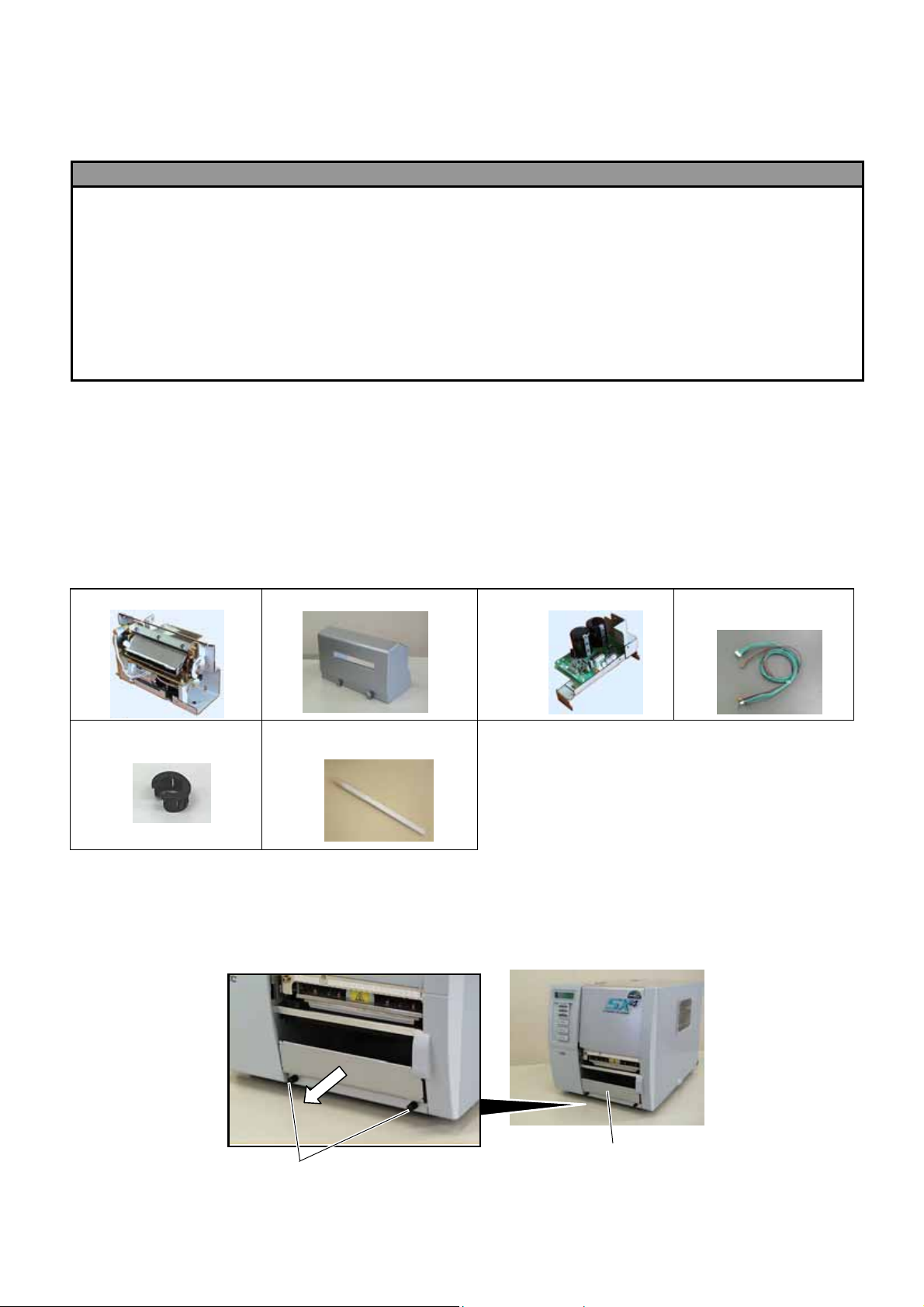
2. PACKING LIST
All the following parts are supplied with the kit. Make sure you have all items shown below.
Cutter Unit (1 pc.)
Cord Bush (1 pc.)
(For B-SX4 only)
Cutter Cover (1 pc.) Cutter Drive Unit (1 pc.) Harness Ass’y
(2-pin & 9-pin) (1 pc.)
Print Head Cleaner (1 pc.)
(P/No.: FMQB0051601)
• Installation Manual (1 copy)
• SM-4x8 Screw (6 pcs.)
3. INSTALLATION PROCEDURE
3.1 Installing the Rotary Cutter Unit on the B-SX4T Series
1) Turn the power off and disconnect the power cord.
2) Remove the two black screws to detach the front plate.
NOTE: Retain the two black screws and front plate.
Black Screws
- 1 -
Front Plate
Page 2
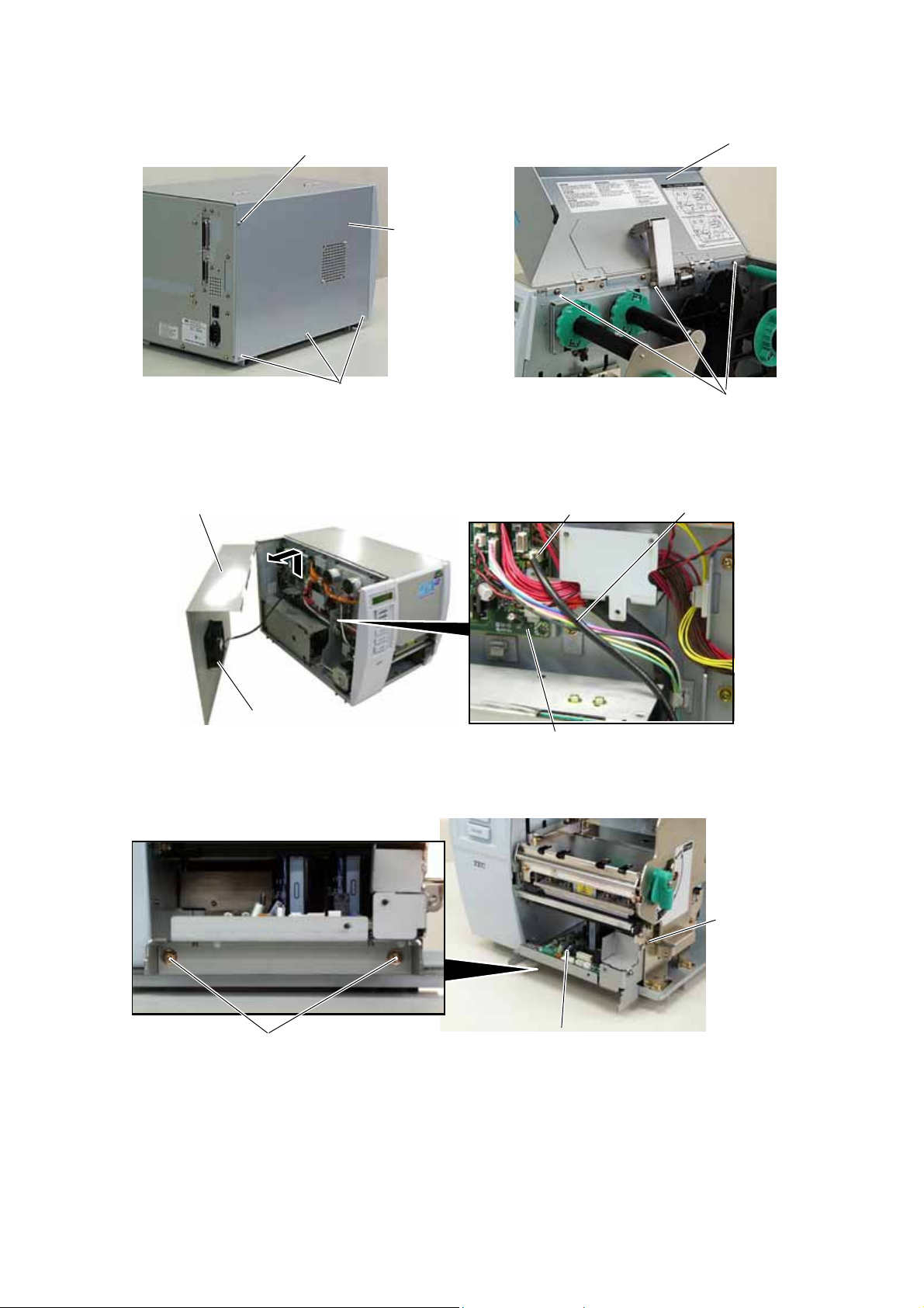
3) Remove the four B-4x5 screws from the side panel (L).
4) Open the top cover and remove the three P-4x8 screws that secure the side panel (L).
B-4x5 Screw
Top Cover
B-4x5 Screw
Side Panel (L)
P-4x8 Screw
5) Lift the side panel (L) and put it aside.
6) Disconnect the fan motor harness from CN19 on the Main PC board, and then separate the side
panel (L).
Side Panel (L)
CN19
Fan Motor Harness
Fan Motor
Main PC Board
7) Fix the cutter drive unit to the printer with the three SM-4x8 screws.
SM-4x8 Screw
Cutter Drive Unit
SM-4x8 Screw
- 2 -
Page 3
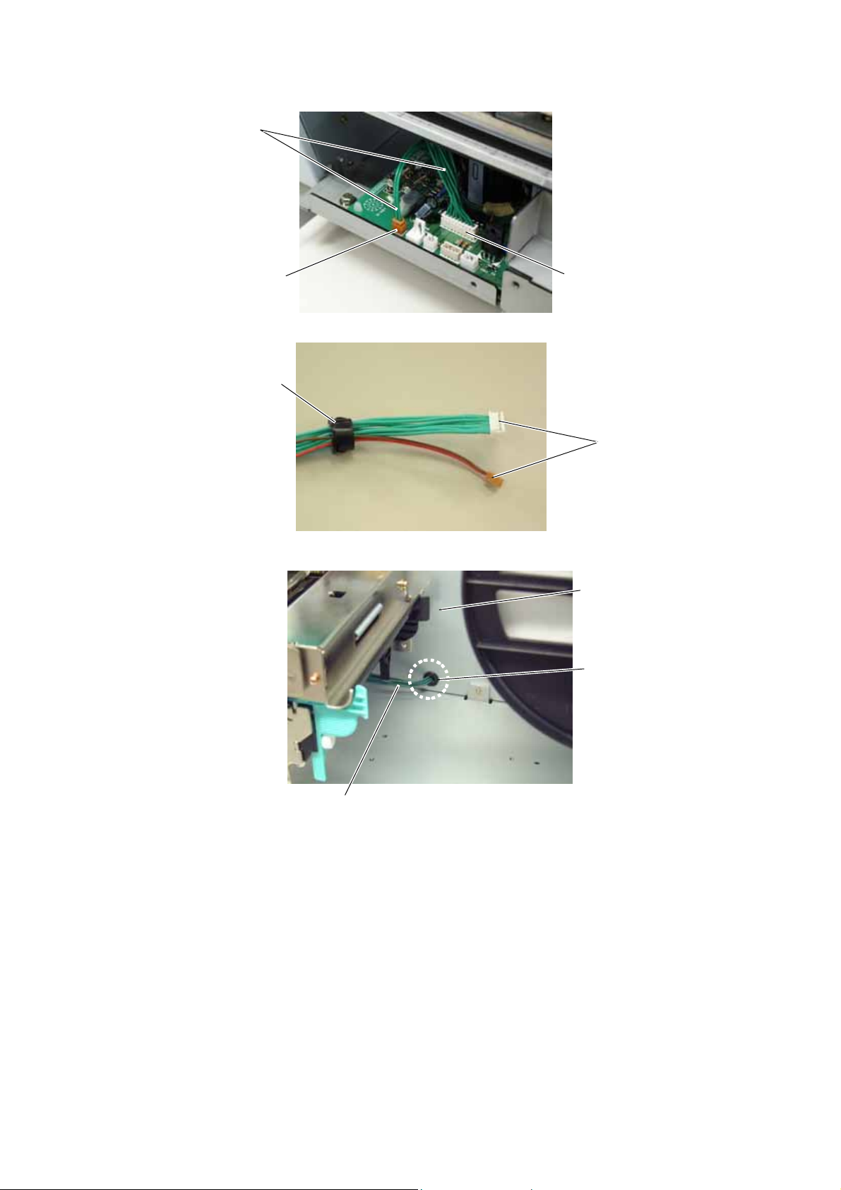
8) Connect the 9-pin connector of the harness ass’y to CN7 and 2-pin connector to CN9 on the cutter
driver unit, respectively.
Harness Ass’y
CN9 (2 pins)
CN7 (9 pins)
9) Fit the bush to the harness ass’y in the orientation as shown below.
Bush
Harness Ass’y
10) Insert the harness ass’y into the hole in the main frame. Fit the bush into the hole.
Main Frame
Hole
Harness Ass’y
- 3 -
Page 4
r
r
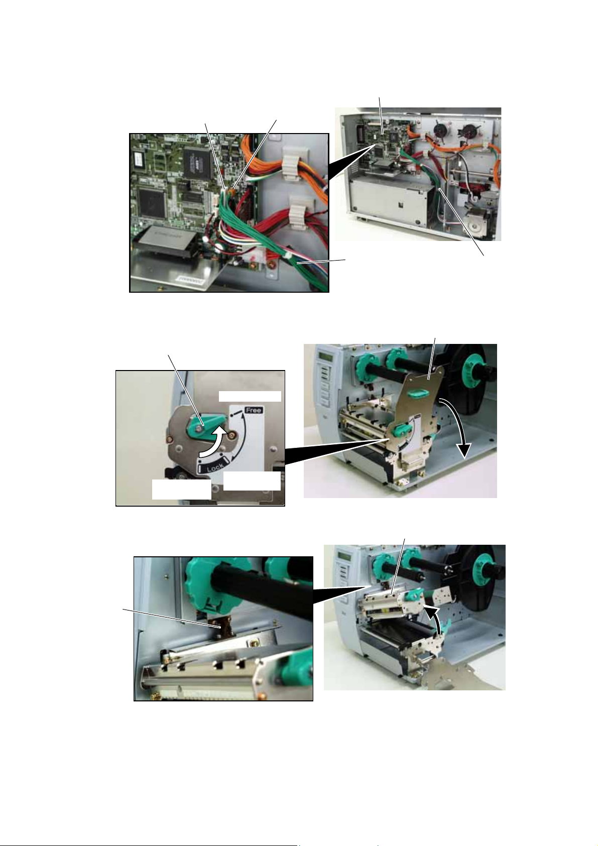
11) Fix the harness ass’y with the clamp.
12) Connect the 9-pin connector of the harness ass’y to CN15, and 2-pin connector to CN18 on the
Main PC board, respectively.
Main PC Board
CN15 (9 pins)
CN18 (2 pins)
Harness Ass’y
Clamp
13) Turn the head lever counterclockwise to Free position.
14) Open the ribbon shaft holder plate.
Head Leve
Ribbon Shaft Holder Plate
Free position
Lock position
(Tag)
Lock position
(Label)
15) Raise the print head block until it stops.
Print Head Block
Stoppe
- 4 -
Page 5
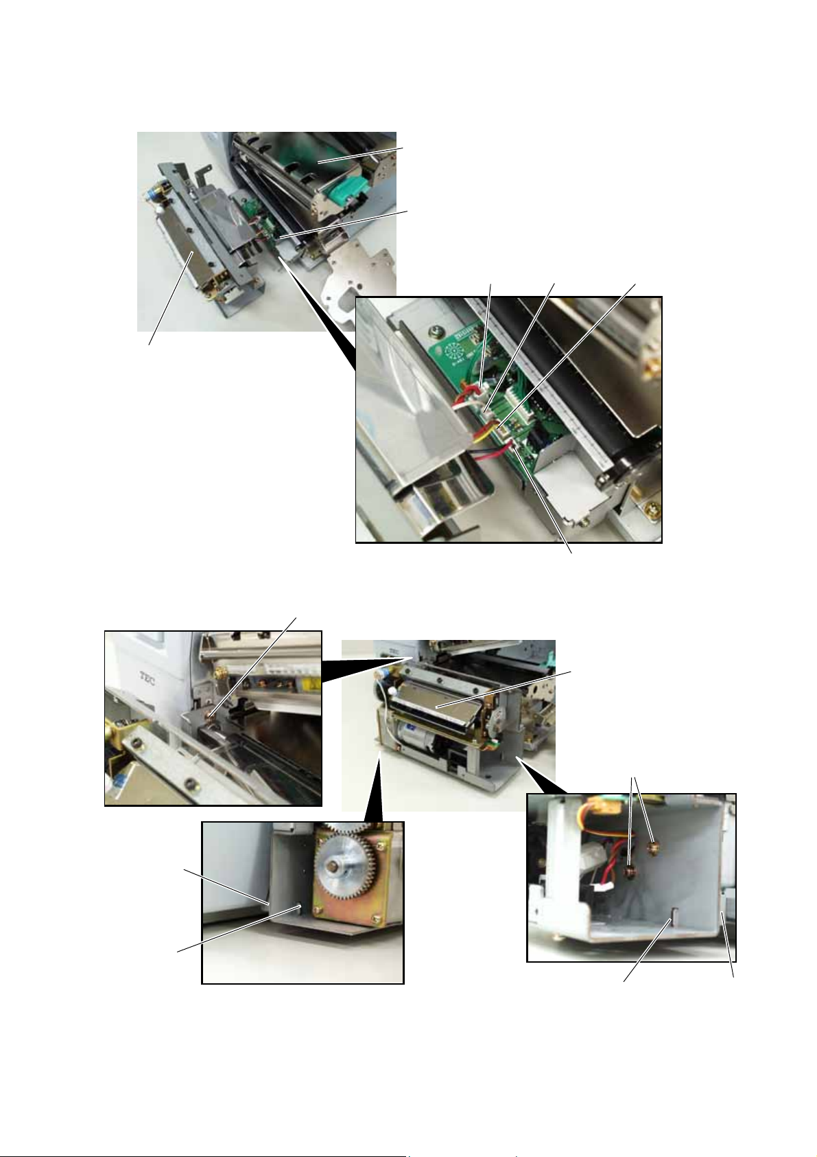
16) Connect the four harnesses of the cutter unit to CN8, CN10, CN11 and CN12 on the cutter drive
unit.
Print Head Block
Cutter Drive Unit
CN8
CN12
CN10
Cutter Unit
CN11
17) Fit the two tabs of the cutter drive unit into the notches, and then fix the cutter unit with the three
SM-4x8 screws.
SM-4 x 8 Screw
Cutter Unit
SM-4 x 8 Screw
Tab
Notch
Notch
Tab
- 5 -
Page 6
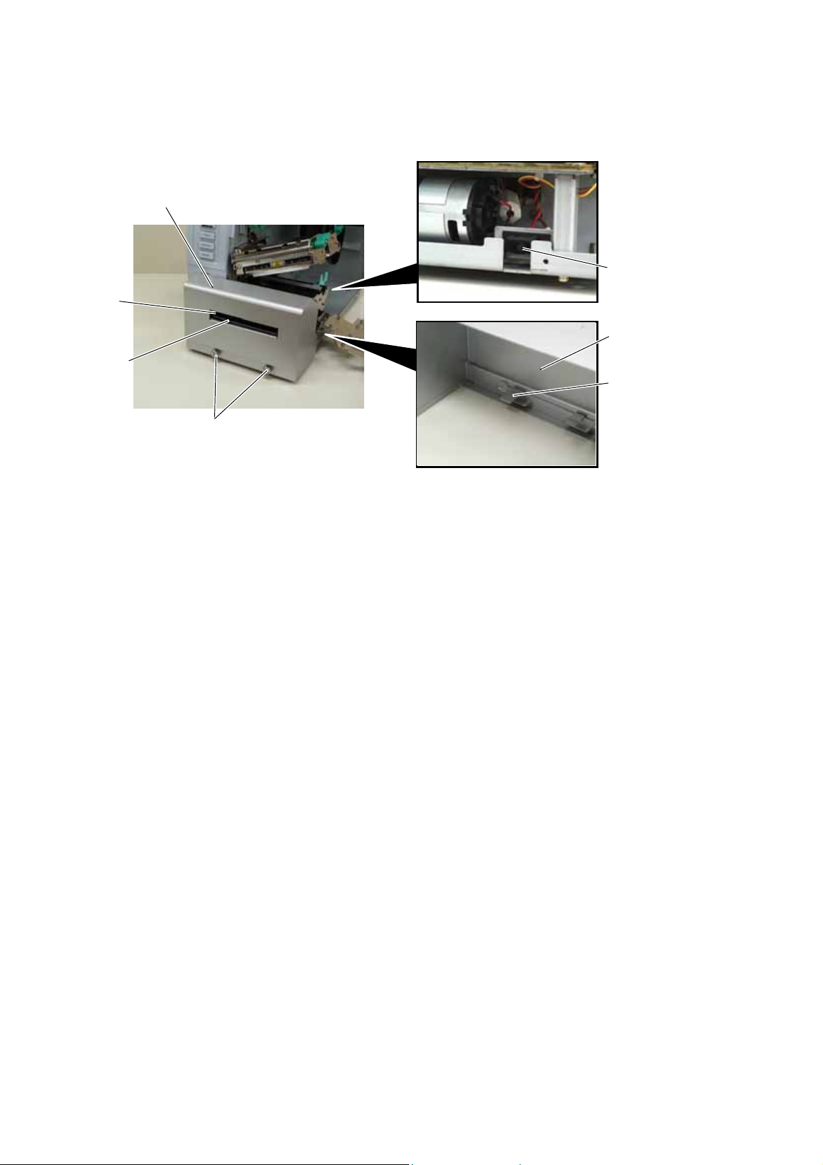
18) Attach the cutter cover to the cutter unit with the two screws so that the tab of the cutter cover turns
on the cutter cover open switch.
NOTES: 1. Be careful not to pinch the cutter harness by the cutter cover.
2. Make sure that the anti-static brush is protruding from the media outlet.
Cutter Cover
Anti-static
Brush
Media Outlet
Cutter Cover
Open Switch
Cutter Cover
Tab
Screw
19) Close the print head block and ribbon shaft holder plate.
NOTE: DO NOT excessively push down the print head block to close it. Doing so may cause a
failure of the print head block or damage to the print head.
20) Reassemble the side panel (L) and close the top cover. Finally check the cutter operation.
- 6 -
Page 7
3.2 Installing the Rotary Cutter Unit on the B-SX5T Series
Since the strip module is standard on the B-SX5T series, it is necessary to remove the rewinder guide plate,
strip sensor, etc. before installing the cutter module.
1) Turn the power off and disconnect the power cord.
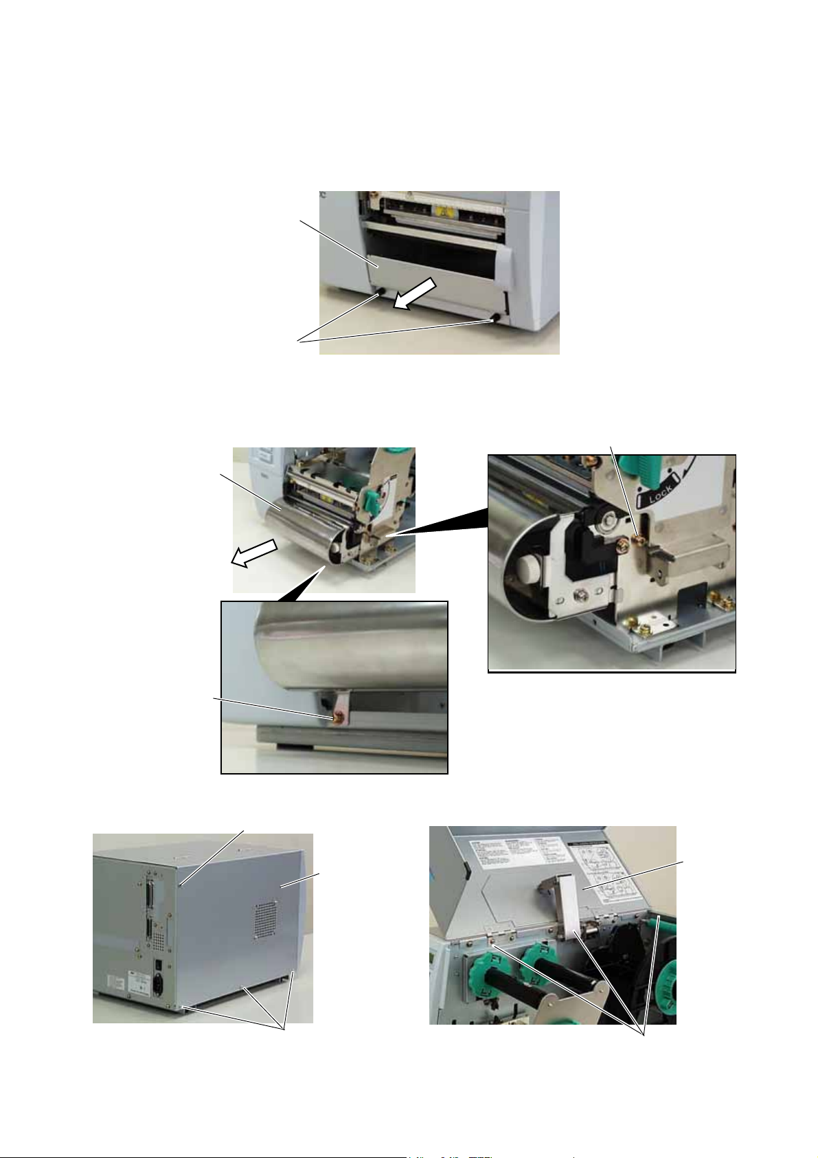
2) When the printer is used in the batch or strip mode:
Remove the two black screws to detach the front plate.
NOTE: Retain the two black screws and front plate.
When the printer is used in the built-in rewinder mode:
Open the top cover, remove the two SMW-4x8 screws, and detach the rewinder guide plate from the
printer.
Rewinder Guide Plate
SMW-4x8B Screw
3)
Remove the four B-4x5 screws from the side panel (L).
4) Open the top cover and remove the three P-4x8 screws that secure the side panel (L).
Front Plate
Black Screws
B-4x5 Screw
B-4x5 Screw
Side Panel (L)
SMW-4x8B Screw
Top Cover
P-4x8 Screw
- 7 -
Page 8

5) Lift the side panel (L) and put it aside.
y
6)
Disconnect the fan motor harness from CN19 on the Main PC board, and then separate the side panel
(L).
Side Panel (L) Fan Motor Harness
CN19
7) Remove the SM-4x8 screw that secures the operation panel ass’y.
8) Half open the top cover, otherwise the operation panel ass’y cannot be removed from the printer.
9) Lift the operation panel ass’y to release the hook, and then remove the operation panel ass’y by
moving it forward.
Operation Panel Ass’
Fan Motor
Main PC Board
SM-4x8 Screw
Top Cover
- 8 -
Page 9

10) Disconnect the operation panel harness from the operation panel ass’y.
r
Operation Panel Ass’y
Operation Panel Harness
Hook
11) Turn the head lever clockwise to Free position.
12) Open the ribbon shaft holder plate.
Head Leve
Ribbon Shaft Holder Plate
Free position
Lock position
(Tag)
Lock position
(Label)
- 9 -
Page 10

13) Raise the print head block until it stops.
r
Print Head Block
Stoppe
14)
Remove the two SMW-4x8 screws that secure the strip sensors (TR) and (LED).
15)
Release the strip sensor (LED) harness from the cable clamp, and disconnect it from the shorter harness
of the strip sensor harness (TR).
SMW-4x8B Screw
SMW-4x8B Screw
Strip Sensor (Tr)
Strip Sensor (LED)
Shorter Harness of the Strip
Sensor Harness (for Tr)
Cable Clamp
Strip Sensor Harness
(for LED)
- 10 -
Page 11

16) Remove the Expansion I/O board from the printer temporarily using the following procedure.
(1) Disconnect the Expansion I/O cable from CN1 on the Expansion I/O board.
(2) Remove the two B-3x6 screws to detach the Expansion I/O board from the printer.
Rear Plate
B-3x6 Screw
Expansion I/O Board
CN1
Expansion I/O Cable
17)
Disconnect the shorter harness of the strip sensor harness (TR) from CN20 on the Main PC board.
Then remove the strip sensor (TR) from the printer.
NOTE:
18)
Disconnect the longer harness of the rewind full sensor (TR) and rewinder harness from CN4 and CN15
on the Main PC board, respectively.
Retain the strip sensors (TR) and (LED), and the strip sensor harness.
Main PC Board
CN4
Shorter Harness of the
Strip Sensor Harness (Tr)
CN15
CN20
NOTE:
Secure the rewinder harness and the longer harness of the rewind full sensor (TR) to the space
under the Main PC board with the cable clamp so that they are not pinched by the covers or
printer’s internal components.
Longer Harness of the
Rewind Full Sensor (Tr)
Rewinder Harness
Main PC Board
Cable Clamp
PS Unit
19)
Reassemble the operation panel ass’y and the expansion I/O board in the reverse order of removal.
- 11 -
Page 12

20) Fix the cutter drive unit to the printer with the three SM-4x8 screws.
SM-4x8 Screw
SM-4x8 Screw
Cutter Drive Unit
21) Connect the 9-pin connector of the harness ass’y to CN7 and 2-pin connector to CN9 on the cutter
driver unit, respectively.
Harness Ass’y
CN9 (2 pins)
CN7 (9 pins)
22) Fit the bush to the harness ass’y in the orientation as shown below.
Bush
Harness Ass’y
23) Insert the harness ass’y into the hole in the main frame. Fit the bush into the hole.
Main Frame
Hole
Harness Ass’y
- 12 -
Page 13

24) Fix the harness ass’y with the clamp.
25) Connect the 9-pin connector of the harness ass’y to CN15, and 2-pin connector to CN18 on the
Main PC board, respectively.
Main PC Board
CN18 (2 pins)CN15 (9 pins)
Harness Ass’y
Clamp
26) Connect the four harnesses of the cutter unit to CN8, CN10, CN11 and CN12 on the cutter drive
unit.
Cutter Drive Unit
CN8
CN12
CN10
Cutter Unit
CN11
- 13 -
Page 14

27) Fit the two tabs of the cutter drive unit into the notches, and then fix the cutter unit with the three
SM-4x8 screws.
SM-4 x 8 Screw
Cutter Unit
SM-4 x 8 Screw
Tab
Notch
Notch
28) Attach the cutter cover to the cutter unit with the two screws so that the tab of the cutter cover turns
on the cutter cover open switch.
NOTES: 1. Be careful not to pinch the cutter harness by the cutter cover.
2. Make sure that the anti-static brush is protruding from the media outlet.
Cutter Cover
Anti-static
Brush
Media Outlet
Cutter Cover Open Switch
Cutter Cover
Tab
Screw
29) Close the print head block and ribbon shaft holder plate.
NOTE: DO NOT excessively push down the print head block to close it. Doing so may cause a
failure of the print head block or damage to the print head.
30) Reassemble the side panel (L) and close the top cover. Finally check the cutter operation.
Tab
- 14 -
Page 15

ロータリーカッターモジュール(B-8204-QM-R) 組込説明書
このたびは「ロータリーカッターモジュール B-8204-QM-R」をお買い上げいただき、誠にありがとうございます。
B-8204-QM-R は、B-SX5T-R シリーズ用のロータリー式カッターモジュールです。
B-8204-QM-R を組み込む前に、パッケージに次のものがすべて揃っているか確認してください。
万一、不足しているものがある場合は、お買い上げの販売店までご連絡ください。
●カッター機構部(1台)
●コードブッシュ(1個)
●カッターカバー(1個) ●カッター制御部(1個) ●カッターケーブル
●ヘッドクリーナー(1本)
●セムスネジ SM-4x8(6個)
●組込説明書(1冊…本書)
●本書の手順に従って組み込むこと
手順を無視して組み込むと、火災・感電の恐れがあります。
本書の手順や指示を無視して組み込んだ場合、その結果に対して当社は一切の責任を負いません。
●組み込む前にプリンタの電源スイッチをOFFにし、電源プラグをコンセントから抜くこと
電源が ON 状態で組み込むと、火災・感電・けがの恐れがあります。
●プリンタのトップカバーは、左側に倒すように全開にすること
中途半端な状態にしておくと勝手に閉まり、けがの原因となることがあります。
●カッターの刃に手や指を触れないこと
けがの原因となることがあります。
●印字直後は、印字ヘッドおよびヘッド周辺部に手を触れないこと
やけどの原因となることがあります。
注意事項(組込作業をされる方へ)
(1セット)
補足 ロータリーカッターモジュール(B-8204-QM-R)とハクリモジュール(B-9904-H-R)を同時に組み込むこと
はできません。
-15 -
Page 16

■組込手順
1) プリンタの電源スイッチを OFF にし、電源プラグをコンセントから抜きます。
2) 用紙発行口下側の黒い化粧ネジ2本を外し、目隠し板を取り外します。
補足 目隠し板および化粧ネジは、紛失しないよう大切に保管してください。
3) 左サイドカバーからネジ(B-4x5)4本を外します。
4) トップカバーを全開にし、左サイドカバーを固定しているネジ(P-4x8)3本を外します。
5) 左サイドカバーを少し持ち上げながら外してそばに置きます。
6) Main PC板のCN19から冷却ファンケーブルを抜き、左サイドカバーをプリンタから取り外します。
左サイドカバー
化粧ネジ
ネジ(B-4x5)
左サイド
カバー
ネジ(B-4x5)
CN19
冷却ファン
Main PC 板
目隠し板
ネジ(P-4x8)
冷却ファンケーブル
トップ
カバー
-16 -
Page 17

7) ヘッドレバーを Free の位置まで回します。
8) リボンシャフト固定板を静かに右側へ倒します。
ヘッドレバー
リボンシャフト固定板
Free 位置
Lock 位置
(タグ)
Lock 位置
(ラベル)
9) 印字ヘッド機構部を持ち上げてロックします。
印字ヘッド機構部
ヘッド固定具
10) セムスネジ(SM-4x8)3本で、カッター制御部を印字ヘッド機構部の下に取り付けます。
ネジ(SM-4x8)
カッター制御部
ネジ(SM-4x8)
-17 -
Page 18

ブ
ドブ
ドブ
ブ
11) カッターケーブルをカッター制御部の CN7 と CN9 へ接続します。
カッターケー
ル
CN9 (2ピン)
CN7 (9ピン)
12) カッターケーブルにコードブッシュを取り付けます。
コー
ッシュ
カッターケーブル
13) カッターケーブルをメインフレーム下側の丸穴に通し、コードブッシュをはめ込みます。
メインフレーム
コー
カッターケー
ル
ッシュ
-18 -
Page 19

板
機構部
御部
ブ
14) コードクランプでカッターケーブルを止め、Main PC 板の CN15 と CN18 へカッターケーブルを接続します。
Main PC
CN18 (2ピン)CN15 (9ピン)
カッターケー
ル
ケーブル
クランプ
15) カッター機構部の4本のコネクタケーブルを、カッター制御部の CN8,CN10, CN11 および CN12 へ接続し
ます。
カッター制
CN8
CN12
CN10
カッター
CN11
-19 -
Page 20

機構部
角穴
突起部
バ
ラシ
突起部
バ
突起部
角穴
16) カッター制御部の2つの突起部とカッター機構部の角穴を合わせ、セムスネジ(SM-4x8)3本でカッター
機構部を固定します。
ネジ(SM-4 x 8)
カッター
ネジ(SM-4 x 8)
補足 ケーブル類をかまないように、カッター機構部を固定してください。
17) カッターカバーを取り付け、カバーに付いている2本の化粧ネジで固定します。
カッターカ
ー
除電
ブ
カッターカバーSW
カッターカ
の内側
用紙発行口
ー
化粧ネジ
補足
・カッターカバーを取り付けたとき、カバー内側の突起部がカッターカバースイッチを ON にしていることを確認してくだ
さい。
・ケーブル類をかまないように、カッターカバーを取り付けてください。
・用紙発行口から除電ブラシがはみ出していることを確認してください。
-20 -
Page 21

18) 印字ヘッド機構部のロックを解除して静かに下ろし、リボンシャフト固定板を閉めます。
19) 冷却ファンケーブルを接続し、左サイドカバーを取り付けます。
補足
ケーブル類をかまないように、左サイドカバーを確実に取り付けてください。
20) 用紙(必要ならばリボンも)をセットし、ヘッドレバーを Lock 位置まで回します。
21) プリンタの電源を ON にし、正しくカットされることを確認してください。
-21 -
Page 22

FMMB0067606
Printed in Japan
EO2-38009F
Ⓒ東芝テック株式会社 2008
 Loading...