

Page 1

TOSHIBA Barcode Printer
B-450-R SERIES
Maintenance Manual
Document No. EO18-33021
Original Jun., 2008
(Revised )
PRINTED IN JAPAN
Page 2

EO18-33021
A
TABLE OF CONTENTS
Page
1. UNPACKING............................................................................................................................1- 1
1.1 PROCEDURE..................................................................................................................1- 1
1.2 CHECKS..........................................................................................................................1- 1
2. MAJOUR UNIT REPLACEMENT.............................................................................................2- 1
2.1 REPLACING THE CPU PC BOARD ...............................................................................2- 1
2.2 REPLACING THE MOTOR.............................................................................................2- 5
2.2.1 Ribbon Motor .......................................................................................................2- 5
2.2.2 Stepping Motor.....................................................................................................2- 6
2.3 REPLACING THE PS UNIT ............................................................................................2- 7
2.4 REPLACING THE PRINT HEAD....................................................................................2-11
2.5 REPLACING THE MEDIA SENSOR ..............................................................................2-11
2.5.1 Replacing the Sensor PCB (TR).........................................................................3-10
2.5.2 Replacing the Sensor PCB (LED).......................................................................3-11
3. TROUBLESHOOTING .............................................................................................................3- 1
CAUTION!
1. This manual may not be copied in whole or in part without prior written permission of TOSHIBA
TEC.
2. The contents of this manual may be changed without notification.
Copyright © 2008
by TOSHIBA TEC CORPORATION
ll Rights Reserved
570 Ohito, Izunokuni-shi, Shizuoka-ken, JAPAN
Page 3
1. UNPACKING EO18-33021
1.1 PROCEDURE
1. UNPACKING
1.1 PROCEDURE
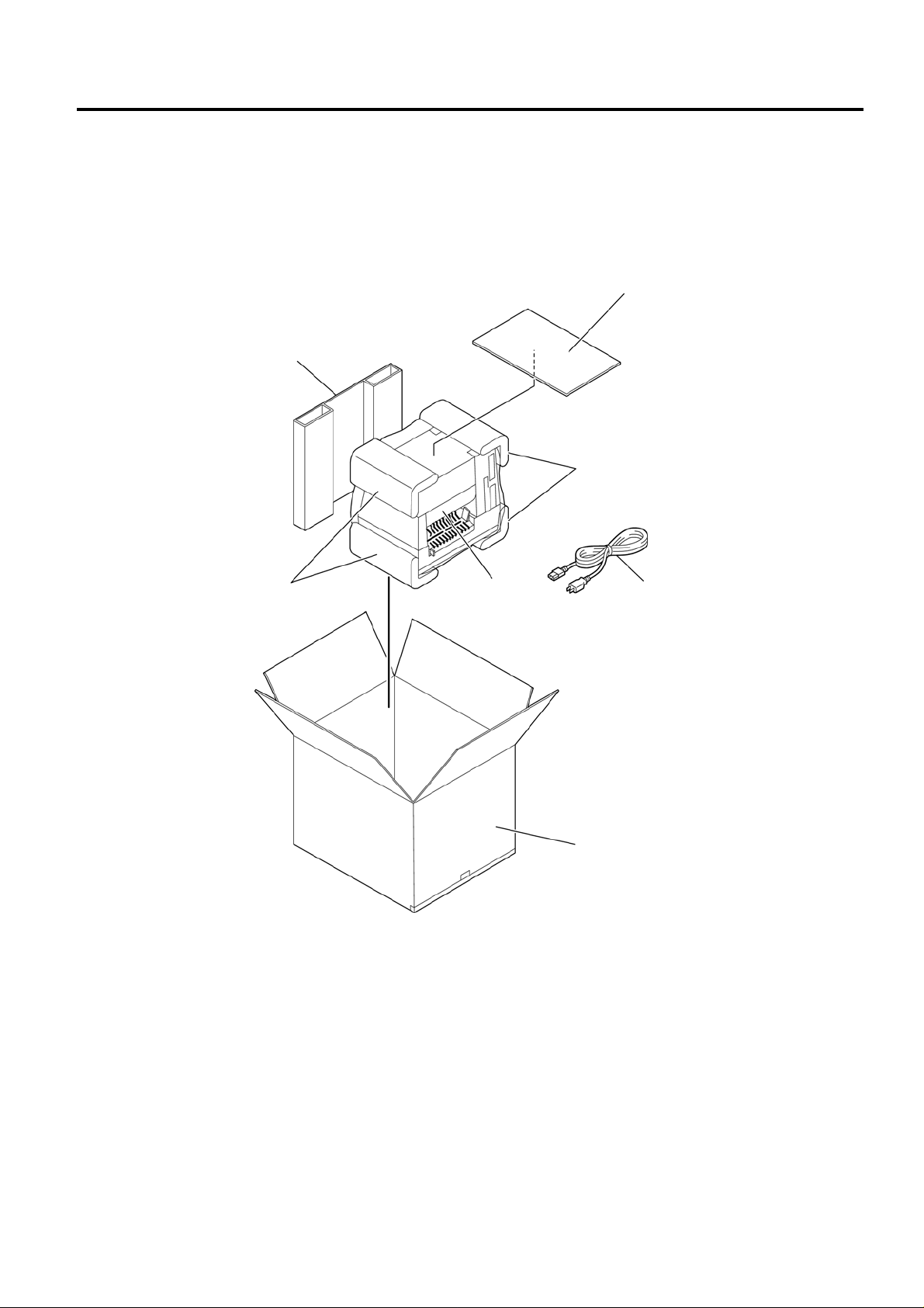
1) Open the carton.
2) Unpack the side pad (R) and cushions and the printer from the carton.
Side Pad (R)
Cushion
3) Place the printer on a level surface.
1.2 CHECKS
Printer
Owner’s Manual
Cushion
Power Cord
Carton
Check for damage or scratches on the printer.
NOTE: Keep the carton, pads and cushions for later transport.
1- 1
Page 4
2. MAJOUR UNIT REPLACEMENT EO18-33021
2.1. REPLACING THE CPU PC BOARD
2. MAJOR UNIT REPLACEMENT
WARNING!
Disconnect power cord before replacing important parts.
Lubrication
CAUTION: 1) Lubrication: During parts replacement.
2) Kinds of oil: 1Kg can. (Part No. 19454906001).
Any machine is generally in its best condition when delivered; therefore, it is necessary to try to keep this
condition. Unexpected failure occurs due to lack of oil, debris or dust. To keep its best condition,
periodically clean the machine and apply proper kinds of oil to each part in which lubrication is needed.
Although the frequency of lubrication varies according to how much the machine is used, at least it is
necessary to lubricate before the machine becomes dry. It is also necessary to wipe off excessive oil as
it collects dirt.
CAUTION: Do not spray the inside of the printer with lubricants. Unsuitable oil can damage
the mechanism.
2.1 REPLACING THE CPU PC BOARD
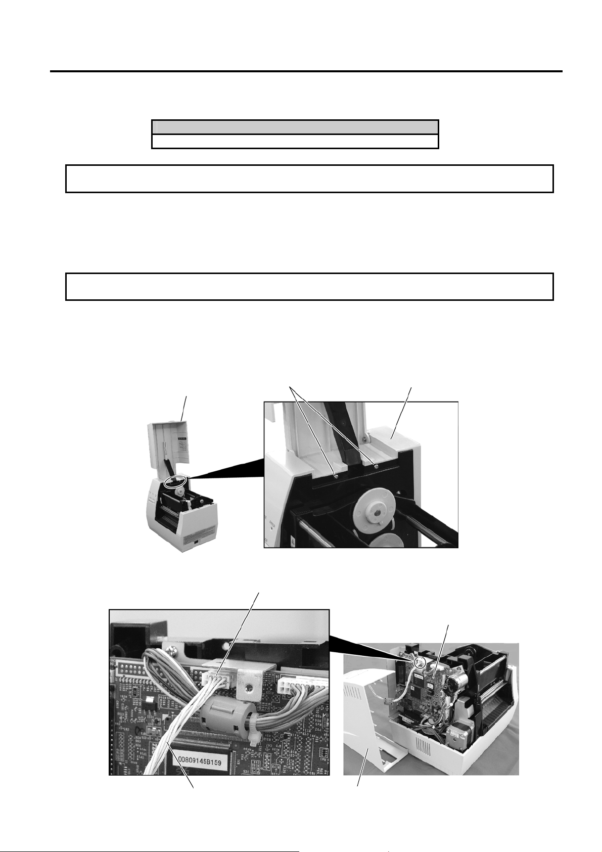
1) Open the Top Cover.
2) Remove the two PT-3x10 screws to detach the Side Cover L.
Top Cover
PT-3x10 Screw
3) Disconnect KEY/LED Harness from connector CN13 on the CPU PC Board.
CN13
KEY/LED Harness
Side Cover L
Side Cover L
CPU PC Board
2- 1
Page 5
2. MAJOUR UNIT REPLACEMENT EO18-33021
2.1. REPLACING THE CPU PC BOARD
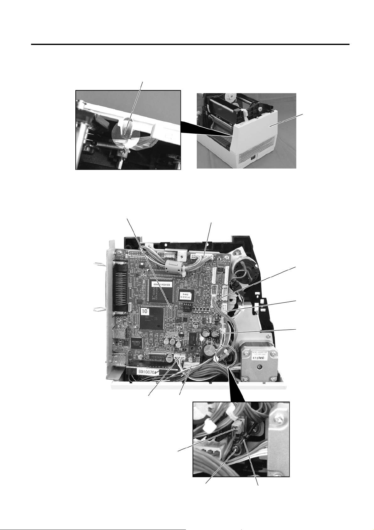
4) Remove the PT-3x10 screw and detach the Side Cover R from the printer.
PT-3x10 Screw
Side Cover R
5) Disconnect the seven harnesses from CN1, CN2, CN5, CN8 to CN10, and CN500 on the CPU PC
Board.
6) Remove the T-3x10 screw and the Ground Wire to detach the CPU PC Board.
CPU PC Board
CN9
CN5
CN2
CN1
CN500
CN8
CN10
T-3x10 screw
Ground Wire
2- 2
Page 6
2. MAJOUR UNIT REPLACEMENT EO18-33021
2.1. REPLACING THE CPU PC BOARD
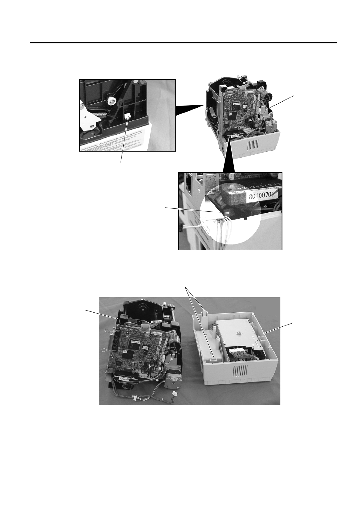
7) Release the two Hooks securing the Printer Unit.
Printer Unit
Hook
Hook
8) Detach the Printer Unit from the Bottom Cover.
Hook
Printer Unit
Bottom Cover
2- 3
Page 7

2. MAJOUR UNIT REPLACEMENT EO18-33021
2.1. REPLACING THE CPU PC BOARD
9) Remove the four screws (T-3x10 and SMW-3x6) and detach the CPU PC B oard Ass’y from the Printer
Block.
T-3x10 Screw
Printer Block
CPU PC Board Ass’y
T-3x10 Screw
T-3x10 Screw
SMW-3x6 Screw
10) Remove the four screws (SMW-3x6 and P-3x6) and detach the CPU PC Board from the PC Board
Attached Plate.
SMW-3x6 Screw
P-3x6 Screw
11) Remove the SMW-3x6 screw, N-3 Nut and Ground Plate.
Ground Plate
SMW-3x6 Screw
N-3 Nut
12) Replace the CPU PC Board with a new one, and then reassemble in the reverse order of removal.
2- 4
Page 8

2. MAJOUR UNIT REPLACEMENT EO18-33021
A
A
2.2. REPLACING THE MOTOR
2.2 REPLACING THE MOTOR
2.2.1 Ribbon Motor
1) Remove the CPU PC Board Ass’y. (Refer to Section 2-1)
2) Remove the two PT-3x10 screws and harnesses to detach the Ribbon Motor Attaching Plate.
Ribbon Motor
ttaching Plate
3) Remove the four SMW-2.6x6 screws to detach the two Ribbon Motors from the Ribbon Motor Attaching
Plate.
SMW-2.6x6 Screw
4) Replace the Ribbon Motors with new ones, and then reassemble in the reverse order of removal.
Harness
PT-3x10 Screw Harness
PT-3x10 Screw
Ribbon Motor
ttaching Plate
FLOIL G-488
SMW-2.6x6 Screw
Ribbon Motor
Ribbon Motor
Ribbon Motor Attaching Plate
2- 5
Page 9

2. MAJOUR UNIT REPLACEMENT EO18-33021
2.2. REPLACING THE MOTOR
2.2.2 Stepping Motor
WARNING!
Be careful not to get burned when handling the stepping motor
since it becomes very hot while printing.
1) Remove the CPU PC Board Ass’y. (Refer to Section 2.1)
2) Remove the two PT-3x10 screws to detach the Stepping Motor Ass’y.
3) Remove the two SMW-3x6 screws to detach the Stepping Motor.
4) Replace the Stepping Motor with a new one, and then reassemble in the reverse order of removal.
PT-3x10 Screw
Stepping Motor Ass’y
SMW-3x6 Screw
Stepping Motor
2- 6
Page 10

2. MAJOUR UNIT REPLACEMENT EO18-33021
2.3. REPLACING THE PS UNIT
2.3 REPLACING THE PS UNIT
WARNING!
Replace only with the same type and rated of fuse for continued protection against risk of fire.
1) Remove the Top Cover and Side Cover L. (Refer to Section 2.1)
2) Remove the PT-3x10 screw to detach the Side Cover R.
3) Disconnect the Power Harness and Fan Motor Harness from CN8 and CN10 on the CPU PC Board.
CN8
PT-3x10 Screw
Side Cover R
Power Harness
CN10
Fan Motor Harness
2- 7
Page 11

2. MAJOUR UNIT REPLACEMENT EO18-33021
2.3. REPLACING THE PS UNIT
4) Release the two Hooks securing the Printer Unit.
Printer Unit
Hook
Hook
5) Detach the Printer Unit from the Bottom Cover.
Hook
PS Unit
Printer Block
Bottom Cover
2- 8
Page 12

2. MAJOUR UNIT REPLACEMENT EO18-33021
2.3. REPLACING THE PS UNIT
6) Detach the PS Unit from the Bottom Cover.
Bottom Cover
PS Unit
7) Replace the PS Unit as an assembly, then, reassemble in the reverse order of steps 1) to 6).
To replace the Fan Motor, Power Harness, Inlet Ass’y, PSU Cover, etc. individually, follow the steps 8)
to 12) provided below.
8) Remove the SMW-3x6, SMW-3x8, and D-3x5 screws to detach the PSU Cover from the PS Unit.
SMW-3x6 Screw
PSU Cover
D-3x5 Screw
SMW-3x8 Screw
9) Disconnect the Power Harness from CN4 on the PS Unit. Remove the SMW-4x8 screw to release the
Ground Wire of the Inlet Ass’y.
Power Harness
Ground Wire
SMW-4x8 Screw
CN4
2- 9
Page 13

2. MAJOUR UNIT REPLACEMENT EO18-33021
2.3. REPLACING THE PS UNIT
10) Push both sides of the Power Switch with something like pliers and remo ve it from the frame of the PS
Unit. Disconnect the Inlet Ass’y from CN1 on the PS Unit.
Power Switch
Inlet Ass’y
(Connector)
Inlet Ass’y
CN1
11) Remove the SMW-3x4 screw to detach the Fan Motor Attachment Plate from the PS Unit.
SMW-3x4 Screw
Fan Motor Attachment Plate
12) After replacing the individual part with a new one as necessary, reassemble in the reverse order of steps
8) to 11).
2- 10
Page 14

2. MAJOUR UNIT REPLACEMENT EO18-33021
t
t
2.4. REPLACING THE PRINT HEAD
2.4 REPLACING THE PRINT HEAD
CAUTION: 1. NEVER touch the element when handling the print head.
2. NEVER touch the connector pins Touching them may cause a static electric
discharge which will damage the print head.
1) Open the Top Cover.
2) Push down the Head Release Lever R to open the Print Head Block.
Head Release Lever R
3) Disconnect the two Print Head Harnesses. Then, pull the Print Head Ass’y upward while pulling the
Knob.
NEVER touch the elemen
when handling the prin
head.
Print Head Ass’y
Harness
Knob
4) Replace the Print Head with a new one, and then reassemble in the reverse order of removal.
Print Head Block
Print Head Ass’y
2- 11
Page 15

2. MAJOUR UNIT REPLACEMENT EO18-33021
2.5. REPLACING THE MEDIA SENSOR
2.5 REPLACING THE MEDIA SENSOR
2.5.1 Replacing the Sensor PCB (TR)
1) Push down the Head Release Lever R to open the Print Head Block. (Refer to Section 2.4)
2) Remove the Sensor Holder from the Sensor Holder Arm.
3) Remove the Sensor Cover Sheet from the Sensor Holder.
Sensor Holder Sensor Cover Sheet
4) Release the Sensor Hold er while spreading the tabs of the Sensor Holder. Be careful not to break the
tabs when spreading them.
Sensor Holder Arm
Sensor Holder
Sensor Holder
Tab
Sensor Cover Sheet
Fixed Portion
Sensor Holder
2- 12
Page 16

2. MAJOUR UNIT REPLACEMENT EO18-33021
2.5. REPLACING THE MEDIA SENSOR
5) Disconnect the harness from the Sensor PCB (TR), and remove the Sensor PCB (TR) from the Sensor
Holder by releasing the two Rivets.
Sensor PCB (TR)
Connector
Sensor Holder
Harness
Rivet
6) Replace the Sensor PCB (TR) with a new one, and then reassemble in the reverse order of removal.
2- 13
Page 17

2. MAJOUR UNIT REPLACEMENT EO18-33021
2.5. REPLACING THE MEDIA SENSOR
2.5.2 Replacing the Sensor PCB (LED)
1) Open the Top Cover.
2) Remove the two PT-3x10 screws to detach the Side Cover L.
Top Cover
PT-3x10 Screw
3) Disconnect KEY/LED Harness from connector CN13 on the CPU PC Board.
CN13
KEY/LED Harness
Side Cover L
4) Remove the PT-3x10 screw and detach the Side Cover R from the printer.
PT-3x10 Screw
Side Cover L
CPU PC Board
Side Cover R
2- 14
Page 18

2. MAJOUR UNIT REPLACEMENT EO18-33021
2.5. REPLACING THE MEDIA SENSOR
5) Disconnect the Power Harness and Fan Motor Harness from CN8 and CN10 on the CPU PC Board.
CN8
Power Harness
CN10
Fan Motor Harness
6) Release the two Hooks securing the Printer Unit.
Printer Unit
Hook
Hook
2- 15
Page 19

2. MAJOUR UNIT REPLACEMENT EO18-33021
2.5. REPLACING THE MEDIA SENSOR
7) Detach the Printer Unit from the Bottom Cover.
Hook
Printer Unit
Bottom Cover
8) Disconnect the harness from the Sensor PCB (LED) which is attached to the bottom of the Printer Unit.
Then remove the Rivet to detach the Sensor PCB (LED) from the Printer Unit.
Harness
Rivet Printer Unit
Sensor PCB (LED)
9) Replace the Sensor PCB (LED) with a new one, and then reassemble in the reverse order of removal.
2- 16
Page 20

3. TROUBLESHOOTING EO18-33021
3. TROUBLESHOOTING
3. TROUBLESHOOTING
Problems Cause Solution
Power is not turned ON. 1. Input voltage to the printer is not
within the rated voltage.
2. Output voltage from the printer is not
within the rated voltage.
3. MAIN PC Board is not applied with
voltage.
4. Failure of MAIN PC board.
LED does not light. 1. Failure of the KEYLED PC board.
2. Failure of the KEYLED harness.
3. Failure of the MAIN PC board.
Poor printing. 1. The print paper is of poor quality.
2. Dirty print head.
3. The head lever fastens the print head
incompletely.
4. Alignment adjustment of the print
head is improper.
Printer does not print. 1. Print head failure.
2. Connection of the print head
connector is incomplete, a bad
contact, or broken wires.
3. Failure of the MAIN PC board.
4. Failure of the software.
5. Failure of the printer cable.
Dot missing. 1. Broken element of the print head.
2. Broken wires of the print head cable.
3. Failure of the MAIN PC board.
Blurred print. 1. Poor quality of paper.
2. Dust is attached to the paper.
Label feed failure. 1. Paper is not set properly.
2. Paper of poor quality.
3. Improper adjustment of the feed gap
sensor or black mark sensor.
4. Failure of the feed gap sensor or
blackmark sensor.
5. Labels cannot be stripped off the
backing paper or the backing paper
with labels cannot be would properly.
6. The cutter mechanism is not installed
properly.
7. Failure of the stepping motor.
Communication error. 1. Failure of the communication cable.
2. Failure of the RS-232C interface.
3. Failure of the communication
connector.
4. Failure of the PC or application
software.
5. Failure of the MAIN PC board.
・ Replace the power cord or power
inlet.
・ Replace the PS unit.
・ Replace the power harness.
・ Replace the MAIN PC board.
・ Replace the KEYLED PC board.
・ Replace the KEYLED harness.
・ Replace the MAIN PC board.
・ Use the paper approved by
TOSHIBA TEC.
・ Clean the print head.
・Fasten the head lever completely.
・ Re-adjust the print head.
・ Replace the print head.
・ Connect the harness completely,
or replace the harness.
・ Replace the MAIN PC board.
・ Check the program.
・ Replace the printer cable.
・ Replace the print head.
・ Replace the print head harness.
・ Replace the MAIN PC board.
・ Use only TOSHIBA TEC specified
paper.
・ Clean the print head and remove
the dust from the paper.
・ Set the paper properly.
・ Use the paper approved by
TOSHIBA TEC.
・ Re-adjust the sensor.
・ Replace the feed gap sensor or
black mark sensor.
・Replace the take-up motor or
black mark sensor.
・
・ Install the cutter mechanism
properly.
・ Replace the stepping motor or
MAIN PC board.
・ Replace the cable.
・ Replace the serial I/F Board.
・ Replace the connector.
・ Modify the program.
・ Replace the MAIN PC board.
3- 1
 Loading...