

Page 1
TEC Bar Code Printer
B-30 SERIES
Owirrer^s WinW
TOSHIBA TSC CORPORATIOIM
Page 2

EM1-33004
WARNING
This equipment generates, uses, and can radiate radio frequency energy and if not installed
and used in accordance with the instruction manual, may cause interference to radio
communications, it has been tested and found to comply with the limits for a Class A
computing device pursuant to Subpart J of Part 15 of FCC Rules, which are designed to
provide reasonable protection against such interference when operated in a commercial
environment. Operation of this equipment in a residential area is likely to cause interference
in which case the user at his own expense will be required to take whatever measures may
be required to correct the interference.
(for U.S.A. only)
WARNING
“THIS DIGITAL APPARATUS DOES NOT EXCEED THE CLASS A LIMITS FOR RADIO
NOISE EMISSIONS FROM DIGITAL APPARATUS SET OUT IN THE RADIO INTERFER
ENCE REGULATIONS OF THE CANADIAN DEPARTMENT OF COMMUNICATIONS."
"LE PRÉSENT APPAREIL NUMÉRIQUE N’EMET PAS DE BRUITS RADIOÉLECTRIQUES
DÉPASSANT LES LIMITES APPLICABLES AUX APPAREILS NUMÉRIQUES DE LA
CLASSE A PRESCRITES DANS LE RÉGLEMENT SUR LE BROUILLAGE RADIOÉLEC
TRIQUE ÉDICTÉ PAR LE MINISTÈRE DES COMMUNICATIONS DU CANADA.”
(for CANADA only)
r
n
L
Copyright ©1999
by TOSHIBA TEC CORPORATION
All Rights Reserved
570 Ohito, Ohito-cho, Tagata-gun, Shtzuoka-ken, JAPAN
Page 3

INTRODUCTION
PRECAUTIONS
EM 1-33004
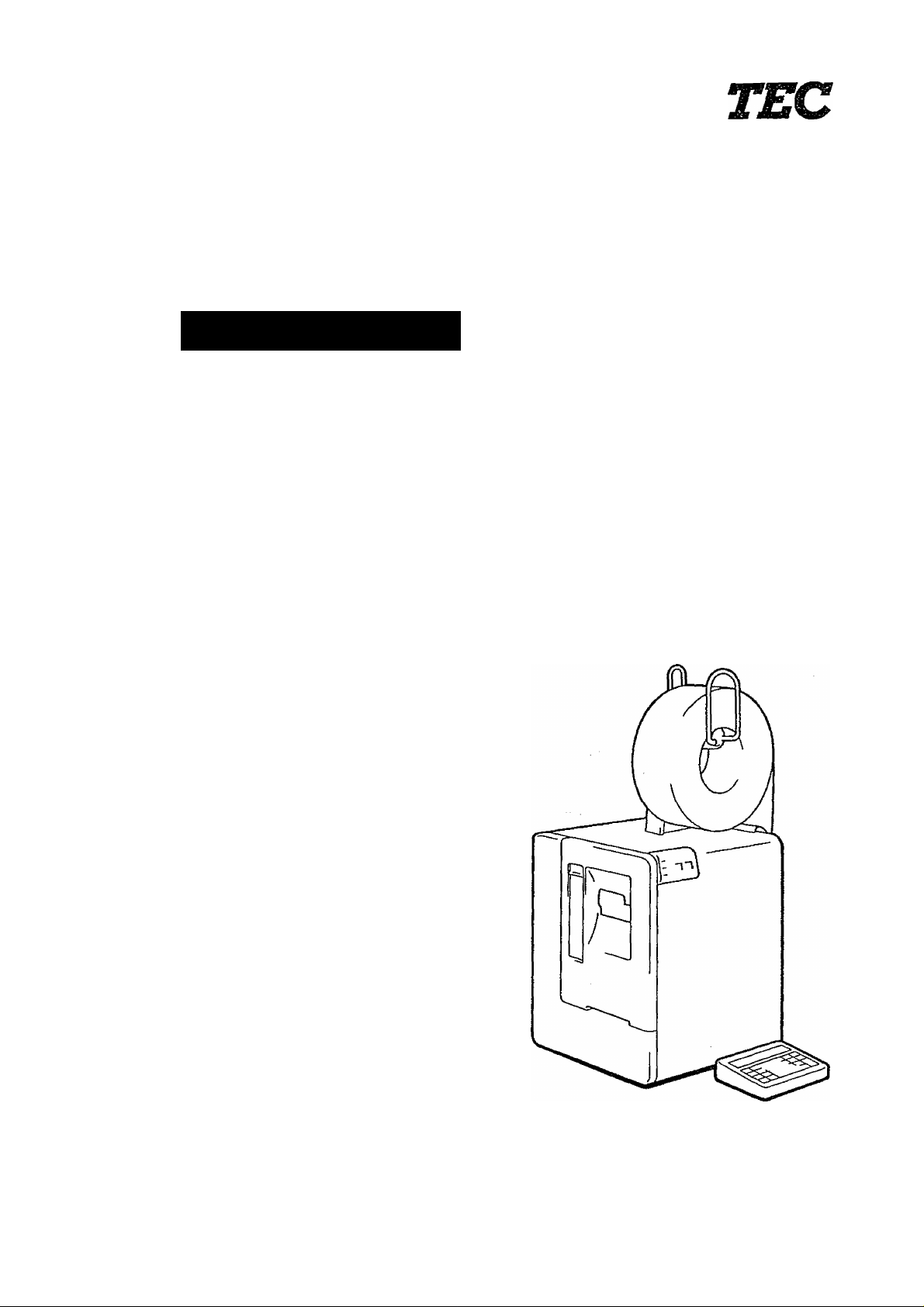
Thank you for choosing the TEC Bar Code Printer B-30-AS3. The B-30-AS3 has been
developed for issuing various kinds of bar codes, and can be connected to a personai
computer, etc., via a TEC interface. The B-30-AS3 adopts a state of the art thermai
printer so that it produces iess noise and more cleariy printed characters. You can
easily select either the thermal transfer or thermal direct printing method.
This manuai contains information about the general set-up and maintenance of the
B-30-AS3 printer, and should be read carefully to obtain maximum performance from
your printer. Since ample consideration has been given to safety, there is no danger
of damaging the printer by erroneous operation.
Should you have any questions concerning the printer, please refer to this manual.
Be sure to keep this manual for future reference.
1. Clean the cover by wiping with a dry cloth or a cloth soaked with detergent and
thoroughly wrung out. NEVER USE THINNER OR OTHER VOLATILE SOLVENT
for cleaning.
2. DO NOT POUR WATER directly on the printer.
3. When in use, avoid locations subject to vibration and direct sunlight.
4. Properly use the TEC-specified label, tag, and ribbon.
5. DO NOT STORE the labels, tags, and ribbons in locations exposed to direct
sunlight, high temperature, high humidity, dust, or gas.
6. Place the printer on a level surface.
CONTENTS
APPLICABLE MODEL
CHAPTER 1
CHAPTER 2
CHAPTER 3
CHAPTER 4
CHAPTER 5
B-30
-S1-EU, UK, US, EU P, UK P, US P
B-30
-H1-EU, UK, US, EU P, UK P, US P
B-30
-C1-EU, UK, US, EU P, UK P, US P
B-30
-S2-EU, UK, MA, EU P, UK P
B-30
-H2-EU, UK, MA, EU P, UK P
B-30
-C2-EU, UK, MA, EU P, UK P
B-30
•S3-US P, AU P, UK P.
B-30
H3-AU P
C3-AU P
B-30
B-30
AS2-US P
B-30
AS3-EU, UK. MA, EU P, US P
B-30-
AH3-EU
B-30
S5-US P
B-30
AS5-US P
B-30-
DS2-UK P
SPECIFICATIONS
BEFORE STARTING UP
INSTALLING THE PRINTER
OPERATION
MAINTENANCE
Page 4

CHAPTER 1
SPECIFICATIONS
EM1-33004
1. PRINTER............................................................................................................ 1- 1
2. SUPPLIES.......................................................................................................... 1- 9
3. RIBBON............................................................................................................. 1- 9
4. DIMENSIONS.................................................................................................... 1-10
5. ACCESSORIES................................................................................................. 1-10
Page 5

1. PRINTER
• B-30-S1/H1/C1
Item
Power Requirement
Current Consumption
Temperature Limits
Relative Humidity
Print Head
Printing Method
Print Speed
Available Printing Width
Bar Code Format
Type Fonts
Rotation
Type
EM 1-33004
B-30-S1 B-30-S1 P B-30-H1
B-30-H1 P B-30-C1
B-30-C1 P
AC 120V ± 10%, 60Hz ... for US version
AC 220V ± 10%, 50Hz ... for EU version
AC 240V ± 10%, 50Hz ... for UK version
220W Max. (Standby: 35W)
5“C to 40'’C(4rF to 104“F)
25% to 85% RH (no condensation)
Thermal Print Head at 76.2 mm (3 inches) wide. 7.6 dots per mm (193
dots per inch)
Thermal Transfer or Thermal Direct
50 mm (2 inches) per sec., 75 mm (3 inches) per sec., 100 mm (4 inches)
per sec.
75.8 mm (2.98 inches) Max.
EAN, UPC, ITF. Code 39, Code 93, Code 128, NW-7
Standard font. Bold Face font. Reduced font, OCR-MA, OCR-B
0“, 90“, 180“, 270“
Issue Method Batch
Weight 17 kg (37.5 lbs)
Memory Card Interface
Serial Interface (RS-232C)
Centronics Interface
1 slot (for 32 KB SRAM card)
O O O O
A O A O
Rewinder B-1103 A
Rewinder B-1103R A
Stacker B-1403
—
Batch or On-demand
A A A
A A A
—
— —
Auto cut
19 kg (41.9 lbs)
O O
A O
—
—
—
—
A A
O: Standard A: Option
1-1
Page 6

Ù B-30-S2/H2/C2 (EU, UK version only)
EM 1-33004
Item
Power Requirement
Current Consumption
Temperature Limits
Relative Humidity
Print Head
Printing Method
Print Speed
Available Printing Width
Bar Code Format
Type Fonts
Rotation
Issue Method
Weight
Memory Card Interface
Type
B-30-S2
B-30-S2 P
B-30-H2
B-30-H2 P
B-30-C2 B-30-C2 P
AC 220V ± 10%. 50Hz ... for EU version
AC 240V ± 10%, 50Hz ... for UK version
220W Max. (Standby: 35W)
5“C to 40‘’C (41“F to 104"F)
25% to 85% RH (no condensation)
Thermal Print Head at 76.2 mm (3 inches) wide, 7.6 dots per mm (193
dots per inch)
Thermal Transfer or Thermal Direct
50 mm (2 inches) per sec., 75 mm (3 inches) per sec., 100 mm (4 inches)
per sec.
75.8 mm (2.98 inches) Max.
EAN, UPC, ITF, Code 39, Code 93, Code 128, NW-7
Standard font. Bold Face font. Reduced font. Outline font, OCR-MA,
OCR-B
0“, 90“, 180“, 270“
Batch
17 kg (37.5 lbs)
Batch or On-demand
Auto cut
19 kg (41.9 lbs)
1 slot (for 32 KB or 64 KB SRAM card)
Serial interface (RS-232C)
Centronics Interface
Memory Card MC32-EX
Memory Card MC64-EX
Rewinder B-1103
Rewinder B-1103R
Stacker B-1403
O
A
A
A
A
A
O
O
A
A
A
A
O
A
A
A
A
A
O
O
A
A
A
A
P
A
A
A
O
O
A
A
O: Standard A: Option
1-2
Page 7
• B-30-S3/H3/C3 (US, AU version only)
EM 1-33004
, ^Version
Item ~~—-—
Power Requirement
S3-US P
AC 120 V
± 10%, 60Hz
Current Consumption
Temperature Limits
Relative Humidity
Print Head
220W Max. (Standby: 35W)
5“C to 40"C(4rF to 104T)
25% to 85% RH (no condensation)
Thermal Print Head at 76.2 mm (3 inches) wide, 7.6 dots per mm
(193 dots per inch)
Printing Method
Print Speed
Thermal Transfer or Thermal Direct
50 mm (2 inches) per sec., 75 mm (3 inches) per sec., 100 mm
(4 inches) per sec,
Available Printing Width
Bar Code Format
Type Fonts
75.8 mm (2.98 inches) Max.
EAN, UPC, ITF, Code 39. Code 93, Code 128, NW-7
Standard font. Bold Face font, Reduced font, Outline font, OCR-MA,
OCR-B
Rotation
0“. 90“, 180“, 270“
Issue Method
Weight 17 kg (37.5 lbs.)
S3-AU P H3-AU P
AC240V ± 10%, 50Hz
Batch
Batch or
on-demand
C3-AU P
Auto cut
19kg (41.9lbs.)
Memory Card interface 1 slot (for 32 KB or 64 KB SRAM card)
Serial Interface (RS-232C)' O O
Centronics Interface O O
Memory Card: MC32-EX A
Memory Card: MC64-EX
Keyboard KB-30-NP
A A
A O
O O
Rewinder B-1103 A A
Rewinder B‘-1103R
Rewinder unit B-1103M
Cutter unit B-1203M A
Stacker B-1403
A A
A A
A
A A
O
O
A
O
A
A
A
-
-
O: Standard A: Option
O
O
O
A
O
—
—
O
A
1-3
Page 8

0 B-30-AS2 (US version only)
EM1-330C
, -——Model
Item ■——
Power Requirement
Current Consumption
Temperature Limits
Relative Humidity
Print Head
Printing Method
Print Speed
Available Printing Width
Bar Code Format
Type Fonts
Rotation
Issue Method
Weight •
Interface
Option
B-30-AS2-US P
AC 120V ± 10%, 60Hz
220W Max. (Standby: 35W)
5“C to 40“C (41“FtOl04“F)
25% to 85% RH (no condensation)
Thermal Print Head at 76.2 mm (3 inches) wide, 10.5 dots per mm (266
dots per inch)
Thermal Transfer or Thermal Direct
50 mm (2 inches) per sec., 75 mm (3 inches) per sec., 100 mm (4 inches)
per sec.
72.9 mm (2.87 inches) Max.
BAN, UPC, ITF, Code 39, Code 93, Code 128, NW-7
Standard font, Bold Face font, Reduced font. Outline font, OCR-MA,
OCR-B
0“, 90”, 180”, 270”
Batch
17 kg (37.5 lbs.)
Memory Card Interface
Serial Interface (RS-232C)
Centronics Interface
Memory Card: MC32-EX, MC64-EX
Keyboard: KB-30-EX
Rewinder: B-1103, B-1103R
.............
1 slot (for 32 KB or 64 KB SRAM card)
• B-30-DS2 (UK version only)
■——-
_____
Item ——
Power Requirement
Current Consumption 220W Max. (Standby: 35W)
Temperature Limits 5”C to 40“C (4rF to 104”F)
■Relative Humidity 25% to 85% RH (no condensation)
Print Head
Printing Method Thermal Transfer or Thermal Direct
Print Speed 50 mm (2 inches) per sec., 75 mm (3 inches) per sec., 100 mm (4 inches)
Available Printing Width
Bar Code Format
Type Fonts
Rotation
Issue Method
Weight 17 kg (37.5 lbs.)
interface Memory Card Interface
Memory Card
Keyboard
Option
Model
AC 240V ± 10%, 50Hz
Thermal Print Head at 76.2 mm (3 inches) wide, 6 dots per mm (152 dots
per inch)
per sec.
74.8 mm (2.94 inches) Max.
EAN, UPC, ITF, Code 39, Code 93, Code 128, NW-7
Standard font. Bold Face font. Reduced font. Outline font, OCR-MA,
OCR-B
0”, 90”, 180”, 270”
Batch
Serial Interface (RS-232C)
Centronics Interface
MC32-EX
KB-30-EX
Rewinder: B-1103, B-1103R
B-30-DS2-UK P
.............
1 slot (for 32 KB SRAM card)
1-4
Page 9

B-30-AS3
EM 1-33004
Item
Power Requirement
Version
US P
AC 120V ±
EU
EU P
AC 220V ± 10%, 50Hz | AC 240V ± 10%, 50Hz
10%, 60Hz
Current Consumption
Temperature Limits
Relative Humidity
Print Head
220W Max. (Standby: 35W)
5°C to 40“C (4rFto 104“F)
25% to 85% RH (no condensation)
Thermal Print Head at 76.2 mm (3 inches) wide, 10.5 dots per mm (266
dots per inch)
Printing Method
Print Speed
Thermal Transfer or Thermal Direct
50 mm (2 inches) per sec., 75 mm (3 inches) per sec., 100 mm (4 inches)
per sec.
Available Printing Width
Bar Code Format
Type Fonts
72.9 mm (2.87 inches) Max.
EAN, UPC, ITF, Code 39, Code 93, Code 128, NW-7
Standard font. Bold Face font, Reduced font. Outline font, OCR-MA,
OCR-B
Rotation
Issue Method
Weight (approx.)
0“, 90", 180", 270“
Batch, On-demand (option), or Auto cut (option)
17 .kg (37.5 lbs.)
Memory Card Interface 1 slot (for 32 KB or 64 KB SRAM card)
Serial Interface (RS-232C) O
Centronics Interface
Keyboard KB-30-EX
O
A
Memory Card MC32-EX A
Memory Card MC64-EX
Rewinder B-1103
Rewinder B-1103R
Rewinder unit B-1103M
Cutter unit B-1203M
Stacker B-1403
A
A
A
A
A
A
O
A
O
A
A
A
A
A
A
A
UK
O
O
O
A
A
A
A
A
A
A
O
A
O
A
A
A
A
A
A
A A
UK P
O
O
o
A
A
A
A
A
A
O: Standard A: Option
1-5
Page 10

© B-30-AH3
“
Item “—
----------------
Model
B-30-AH3-EU
Power Requirement AC 220V ± 10%, 50Hz
Current Consumption 220W Max. (Standby: 35W)
Temperature Limits
Relative Humidity
Print Head
5“C to 40“C (41“F to 104T)
25% to 85% RH (no condensation)
Thermal Print Head at 76.2 mm (3 inches) wide, 10.5 dots per mm (266
dots per inch)
Printing Method Thermal Transfer or Thermal Direct
Print Speed
50 mm (2 inches) per sec., 75 mm (3 inches) per sec., 100 mm (4 inches)
per sec.
Available Printing Width 72.9 mm (2.87 inches) Max.
Bar Code Format
Type Fonts
BAN, UPC, ITF, Code 39, Code 93, Code 128, NW-7
Standard font. Bold Face font, Reduced font, Outline font, OCR-MA,
OCR-B
Rotation O', 90', 180“, 270“
Issue Method
On-demand or Batch
Weight 17 kg (37,5 ibs.)
Interface
Memory Card Interface ............. 1 slot (for 32 KB or 64 KB SRAM card)
Serial Interface (RS-232C)
Option Centronics Interface
Memory Card: MC32-EX, MC64-EX
Keyboard: KB-30-EX
Rewinder: B-1103, B-1103R
EM 1-33004
1-6
Page 11

• B-30-S5 (US version only)
'—
Item
---------
Mode)
Power Requirement
Current Consumption
Temperature Limits
Relative Humidity
Print Head
Printing Method
Print Speed
Available Printing Width
Bar Code Format
Type Fonts
Rotation
Issue Method
Weight
Interface
Option
EM 1-33004
B-30-S5-US P
AC 120V ± 10%, 60Hz
220W Max. (Standby: 35W)
5“C to 40“C (41T to 104“F)
25% to 85% RH (no condensation)
Thermal Print Head at 76.2 mm (3 inches) wide, 7.6 dots per mm (193
dots per inch)
Thermal Transfer or Thermal Direct
50 mm (2 inches) per sec., 75 mm (3 inches) per sec., 100 mm (4 inches)
per sec.
75.8 mm (2.98 inches) Max.
EAN, UPC, ITF, Code 39, Code 93, Code 128, NW-7, MSI
Standard font. Bold Face font, Reduced font. Outline font, OCR-MA,
OCR-B
0“, 90“. 180“, 270“
Batch, On-demand (option), or Auto cut (option)
17 kg (37.5 lbs.)
Memory Card Interface
.............
1 slot (for 32 KB or 64 KB SRAM card)
Serial interface (RS-232C)
Centronics Interface
Memory Card: MC32-EX, MC64-EX
Keyboard: KB-30-EX
Rewinder: B-1103, B-1103R
Rewlnder unit: B-1103M
Cutter unit: B-1203M
Stacker: B-1403
1-7
Page 12

® B-30-AS5 (US version only)
EM 1-33004
~ Model
Item —-—
Power Requirement
Current Consumption
Temperature Limits
Relative Humidity
Print Head
AC 120V ± 10%, 60Hz
220W Max. (Standby: 35W)
5“C to 40"C (41T to 104“F)
25% to 85% RH (no condensation)
Thermal Print Head at 76.2 mm (3 inches) wide, 10.5 dots per mm (266
B-30-AS5-US P
dots per inch)
Printing Method Thermal Transfer or Thermal Direct
Print Speed
50 mm (2 inches) per sec., 75 mm (3 inches) per sec., 100 mm (4 inches)
per sec.
Available Printing Width
Bar Code Format
Type Fonts
72.9 mm (2.87 inches) Max.
BAN, UPC, ITF, Code 39, Code 93, Code 128, NW-7, MSI
Standard font, Bold Face font, Reduced font, Outline font, OCR-MA,
OCR-B
Rotation 0“, 90“, 180“, 270“
Issue Method
Weight
Interface
Batch, On-demand (option), or Auto cut (option)
17 kg (37.5 lbs.)
Memory Card Interface
.............
1 slot (for 32 KB or 64 KB SRAM card)
Serial Interface (RS-232C)
Centronics Interface
Option
Memory Card: MC32-EX, MC64-EX
Keyboard: KB-30-EX
Rewinder: B-1103, B-1103R
Rewinder unit: B-1103M
Cutter unit: B-1203M
Stacker: B-1403
1-8
Page 13
2. SUPPLIES
• B-30-S1/H1/C1/S2/H2/C2/S3/H3/C3/S5
EM 1-33004
^HEPiyjy^
Width
Length
Thickness
Roll Diameter
B-30-AS2/AS3/AH3/AS5
Width
Length
Thickness .13 to .17 mm
Roll Diameter 230 mm (9 inches) Max.
30 to 81 mm (1.18 to 3.18 inches)
15 to 152.4 mm (.59 to 6 inches)
.13 to .17 mm
(.005 to .006 inches)
230 mm (9 inches) Max.
30 to 81 mm (1.18 to 3.18 inches)
15 to 160 mm (.59 to 6.29 inches)
(.005 to .006 inches)
Label
Label
3. RIBBON
Tag
.15 to .26 mm
(.006 to .010 inches)
Tag
.15 to .26 mm
(.006 to .010 inches)
Ribbon Type One-time carbon: Black
Width
Length
Roll Diameter Max. 71 mm (2.79 inches)
48 mm (1.89 inches), 58 mm (2.28 inches), 83 mm (3.26 inches)
400 m (1312 feet)
4. USING B-1403
-
----------------------
Paper
Width
Lenght
supply
Label
Paper with a minimum label-to-label
gap of 4 mm.
30 ~ 81 mm (1.18 to 3.19 inches)
30 ~ 80 mm (1.18 to 3.15 inches)
Tag
Perforated paper cannot be used.
30 — 81 mm (1.18 to 3.19 inches)
30 — 105 mm (1.13 to 4.1 inches)
1-9
Page 14
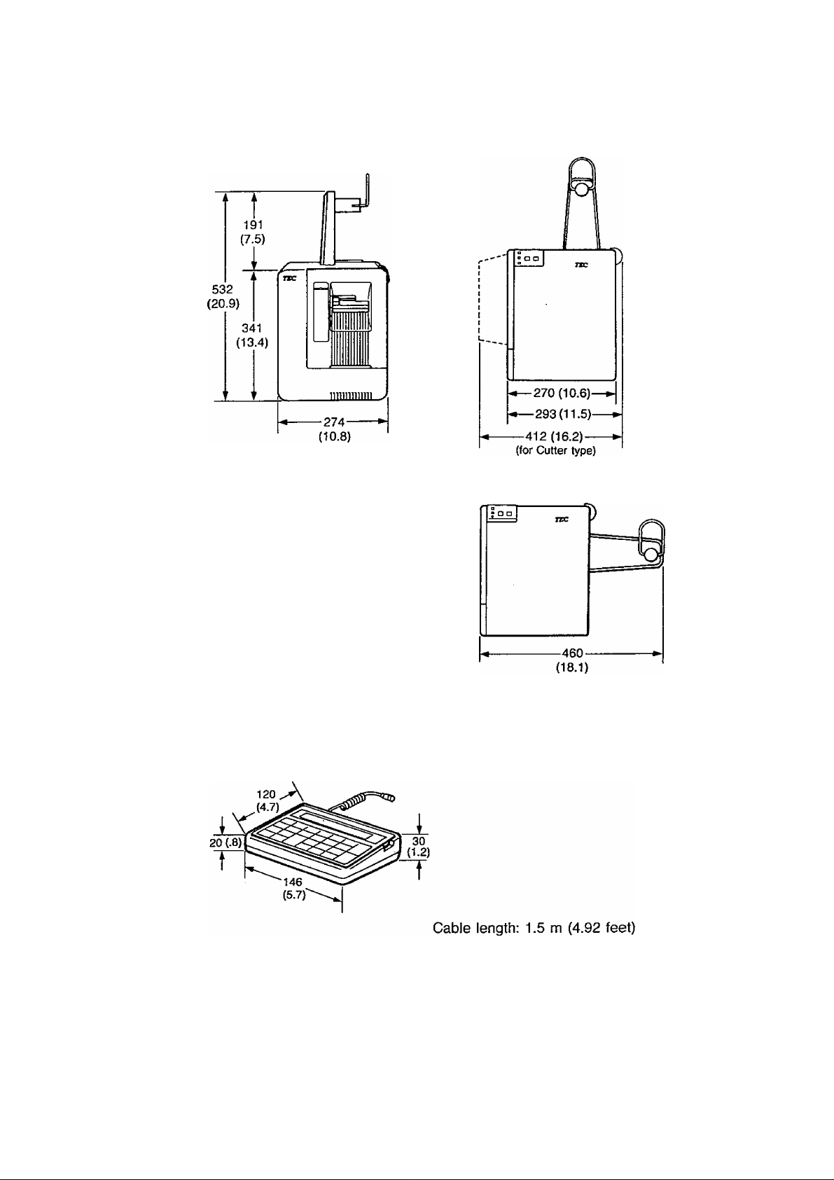
4. DIMENSIONS (approximate)
EM1-33004
M Printer
mm (inches)
Keyboard
5. ACCESSORIES
Make sure you have all the items shown the accessory list on the carton.
NOTE : The specifications are subject to change without notice.
1-10
Weight: 430g (.95 lbs.)
Page 15

CHAPTER 2
BEFORE STARTING UP
EM 1-33004
1. OVERVIEW......................................................:................................................... 2-1
1.1. Front View................................................................................................... 2-1
1.2. Side View..................................................................................................... 2-5
1.3. Keyboard Unit.............................................................................................. 2-5
2. KEY FUNCTIONS................................................................................................ 2-6
Page 16

1. OVERVIEW
1.1. Front View
• B-30-SVDS2
EM 1-33004
• B-30-S2/S3/AS2/AS3/AS5
Supply Roll Holder Unit
POWER Indicator
Lights when the power
is turned on.
r— STOP/RESTART Button
This button is used to stop or
restart printing.
FEED Button
This button is used to feed
the supply.
ON-LINE Indicator
1) Blinks when communicating
with a personal computer.
2) Lights when the printer
prints out.
ERROR Indicator
Lights when the printer does
not operate correctly.
Figure 2-2
Front Door
2-1
Page 17

® B-30-H1
EM 1-33004
■Front Door
B-30-H2/H3/AH3
Figure 2-3.
2-2
Page 18

• B-30-S3/AS3/S5/AS5 (with Rewinder unit B-1103M...option)
EMI-33004
• B-30-C1
2-3
Page 19

« B-30-C2/C3
EM1-33004
O B-30-S3/AS3/S5/AS5 (with Cutter unit B-1203M....Option)
2-4
Page 20

1.2. Side View
Power Switch
AC Power Inlet
1.3. Keyboard Unit
• KB-30-EX
EM 1-33004
Fuse
Figure 2-9.
KB-30-NP
-
TEC
select IlnESTAArj
0 Q
ItIH
mi-
Function keys Numeric keys
foaimtH j
FI
E E
F2
BEE
otMrim'
BEE
1 0 11 . 11=<-
Display (Liquid Crystal Display)
f
■ Intensity Adjustment wheel
\
• Turning up darkens the display.
• Turning down lightens the display.
PRINT
Function keys
ENTER
Figure 2-11.
2-5
Page 21

2. KEY FUNCTIONS 9 KB-30-EX
Key
ENTER
FEED
FI F2
EM1-33004
Function
This key is used for enter-clear of a numeric key.
It is also used to release the printer from an error mode.
This key is used to enter the data recall mode.
This key is used to feed and cut supplies.
NOTICE: The available functions are different depending on the
program used.
Special assigned function.
{These keys are used by service personnel.)
PAUSE
PRESET
COUNT
PRINT/
PROG.
*
This key is used to temporarily stop printing.
It is also used to restart printing supplies after pausing.
This key is used to preset the number of tags/labels you want
to print.
This key is used to start printing.
It is also used to register the next data while the supplies are
being printed.
This key is used to input the data to the printer.
This key is used to separate plural input data.
0
Other
keys
These keys are used to enter numeric data.
These keys are not used during normal operations.
(These keys are also used by service personnel.)
2-6
Page 22

KB-30-NP
EMI-33004
Key
CLEAR
ENTER
FEED
PAUSE
PRINT
3UANT)T\
Function
This key is used for enter-dear of a numeric key.
It is also used to release the printer from an error mode.
This key is used to enter the data to the printer.
This key is used to feed and cut supplies.
NOTICE: The available functions are different depending on the
program used.
This key Is used to temporarily stop printing.
This key is used to start printing.
This key is used to preset the number of tags/labels you want
to print.
RESTART
SELECT
FORMAT
FI
0 ... 9
□
□
F2
□
□
This key is used to select a print format.
This key is used to select a print format.
This key is used to separate plural Input data.
F2 is a purchase order separator.
(These keys are also used by service personnel.)
These keys are used to enter numeric data.
These keys are used to during normal operations to move the
cusor within a data field and to display formats.
2-7
Page 23

CHAPTER 3
INSTALLING THE PRINTER
EM 1-33004
1. CONNECTING THE POWER CORD AND CABLES..........................................
2. INSTALLING THE SUPPLY ROLL HOLDER
3. INSTALLING THE SUPPLY STOPPER B
4. INSTALLING THE PAPER GUIDE
5. INSTALLING THE BACKING PAPER GUIDE..................................................... 3-3
6. MOUNTING THE LOCK AND ADJUSTMENT KNOBS....................................... 3-4
B Adjusting the cutting position............................................................................ 3-4
7. INSTALLING THE STACKER.............................................................................. 3-4
8- INSTALLING THE REWINDER B-1103
......................................................................
.......................................................
............................................................
...............................................................
3-1
3-1
3-2
3-3
3-5
Page 24

1. CONNECTING THE POWER CORD AND CABLES
EM 1-33004
WARNING; The power switch must be off before connecting the power cord.
2. INSTALLING THE SUPPLY ROLL HOLDER
• Installing the supply roll holder on the top of the printer.
a. Remove the cover of the supply roll holder unit, and attach the supply stand to
the top of the printer using the two wing screws.
b. Insert the cover over the top of the supply stand.
3-1
Page 25

EM 1-33004
• Installing the supply roll holder on the right side of the printer (except for B-30-S3/
AS3 with Rewinder unit).
a. Remove the cover of the supply roll holder unit, then remove the supply spool
from the supply stand.
b. Attach the supply stand to the right side of the printer using the two wing screws.
c. Mount the supply spool by inserting it into the horizontal mounting holes of the
supply stand.
d. Attach the cover by inserting it horizontally from the side of the supply stand.
3. INSTALLING THE SUPPLY STOPPER B
Install supply stopper B on the supply roll holder unit when using the narrow supply.
Supply Stopper B
3-2
Page 26

4. INSTALLING THE PAPER GUIDE Place the paper guide in the position shown below.
5. INSTALLING THE BACKING PAPER GUIDE (for B-30-H1/H2/H3) When issuing a label in the “On-demand” mode, mount the backing paper guide in the position shown below and eject the backing paper from the lower exit on the left side of the printer.
EMI-33004
Figure 3-6.
3-3
Page 27

EM 1-33004
6. MOUNTING THE LOCK AND ADJUSTMENT KNOBS (for Cutter type only)
insert each knob. (Align the groove of the knob with the pin on the shaft.)
NOTICE: When inserting the adjustment knob, make sure that the triangular indicator (Á) points to “55” on
the scale.
B Adjusting the cutting position
1. Turn the lock knob to the unlock position.
2. Set the adjustment knob to the designated position.
3. Turn the lock knob to the lock position.
2nd scale: 30 mm ~ 54 mm
3rd scale: 15 mm, 20 mm ~ 25 mm
7. INSTALLING THE STACKER (for Cutter type only)
Assemble the stacker and hang the tabs of the stacker on the tag exit.
3-4
Page 28

8. INSTALLING THE REWINDER B-1103 (Option) To rewind labels issued in batch printing mode, or backing paper in the on-demand
printing mode, attach the Rewinder B-1103 (option) at the position shown below.
• Label (except for Cutter type)
• Backing Paper (for B-30-H1/H2/H3 only)
EM 1-33004
\
Backing Paper Threading
NOTICE: When installing other optional equipments, refer to the owner’s manual provided with those
equipment.
3-5
Page 29

CHAPTER 4
OPERATION
EM 1-33004
1. LOADING THE RIBBON.................................................................................... 4- 1
2. LOADING SUPPLIES........................................................................................ 4- 4
2.1. For B-30-S1/H1/C1/DS2............................................................................ 4- 4
2.2. For B-30-S2/H2/C2/S3/H3/C3/AS2/AS3/AH3............................................ 4- 6
2.3. For B-30-S5/AS5....................................................................................... 4- 8
B Threading the backing paper....................................................................... 4-10
3. INSERTING THE MEMORY CARD.................................................................. 4-11
4. ADJUSTING THE SENSORS
4.1. Black Mark or Feed Gap Sensor
4.2. Label Issue Sensor.................................................................................... 4-12
...........................................................................
...............................................................
4-12
4-12
Page 30

1. LOADING THE RIBBON
EM 1-33004
There are two types of supplies, standard paper and thermal paper.
DO NOT LOAD a ribbon when using thermal paper.
1. Turn the power off.
2. Open the front door.
3. Move the head lock lever to the right to release the print head.
*4. Remove the supply if it has been loaded.
4-1
Page 31

Ribbon Shaft
EM1-33004
5. Load the ribbon.
a. Guide the edge of the ribbon around the ribbon shaft.
b. Place the ribbon rolls onto the two shafts.
c. Insert the ribbon between the ribbon end sensor.
Ribbon Shaft
Figure 4-3.
Figure 4-4.
6. Lock the ribbon rolls.
a. Match the notch on the supply and rewind reels with the protrusion on the
shafts as shown.
Protrusion
4-2
Figure 4-5.
Page 32

b. Pull the head of the shaft while holding the ribbon roll.
NOTICE: Depress the stoppers when removing the ribbon roll.
EM 1-33004
Stopper
Ribbon Shaft
7. Turn the rewind shaft as shown, to pull the ribbon tight.
8. Reload the supply (standard paper).
9. Move the head lock lever to the left to move the print head against the ribbon
and platen.
10. Close the front door.
Head Lock Lever
Rewind Shaft
Figure 4-8.
4-3
Page 33

2. LOADING SUPPLIES
2.1. For B-30-S1/H1/C1/DS2
The printer prints both tags and labels.
1. Turn the power off.
2. Place the supply roll onto the supply roll holder.
3. Open the front door.
4. Move the head lock lever to the right to release
the print head.
5. Thread the supply as shown.
a. Pull enough supply out from the
b. Pull down and hold the guide
c. insert the supply between the
d. Feed the supply to the label exit
EMI-33004
roll to reach the label exit (for
HI and SI types) or platen (for
C1 type).
roller lever, and slide the supply
under the paper guide. Then
release the lever.
label sensors.
Figure 4-11.
or platen as shown below, and
push the inside edge of the
supply against the back wall.
B-30-S1/DS2
B-30-H1
B-30-C1
Figure 4-12.
4-4
Page 34

EM 1-33004
6, Move the head lock lever to position 1 or 2 according to the thickness of the
supply.
7. Close the front door.
4-5
Page 35

2.2. For B-30-S2/H2/C2/S3/H3/C3/AS2/AS3/AH3
The printer prints both tags and labels.
1. Turn the power off.
2. Place the supply roll onto the supply roll holder.
3. Open the front door.
4. Move the head lock lever to the right to release
the print head.
5. Press down the roller open lever to release the skew roller.
EM 1-33004
Figure 4-15.
6. Thread the supply as shown.
a. Pull enough supply out from the roll to reach the paper setting zone.
b. Slide the supply under the paper guide, and push the inside edge of the supply
against the back wall.
Figure 4-16.
4-6
Page 36

7- Push the roller close lever.
EMI-33004
Figure 4-17.
8.. Move the head lock lever to position 1 or 2 according to the thickness of the
supply. ,
9. Close the front door.
4-7
Page 37

2.3. For B-30-S5/AS5
EM 1-33004
The printer prints both tags and labels.
1. Turn the power off.
2. Place the supply roll onto the supply roll holder.
3. Open the front door.
4. Move the head lock lever to the right to release
the print head.
5. Thread the supply as shown.
a. Pull enough supply out from the roll to reach the paper setting zone.
b. Slide the supply under the paper guide, and push the inside edge of the supply
against the back wall.
4-8
Page 38

supply-
EM 1-33004
1 or 2 according to the thickness of the
7. Use the
Figure 4-28, Position 1: Thin paper
Position 2: Thick paper
supply guide to the supply.
supply guide lever to fit «te
Close the front door.
8.
4-9
Page 39

Threading the backing paper (B-30-AH3 and B-30-H3/S3/AS3/S5/AS5 with Rewinder unit)
To rewind backing paper in the on-demand printing mode, thread the backing paper
shown below.
1. Pass the backing paper under the guide rollers.
2. Secure the backing paper to the rewind shaft with clamp.
EM 1-33004
4-10 '
Page 40

3. INSERTING THE MEMORY CARD
1. Turn the power off.
2. Insert the memory card with preregis
tered print data into the memory card
slot.
3. To prevent the memory card from being
removed accidentally, be sure to attach
the memory card cover.
EM 1-33004
WARNING; Replace battery with Hitachi Maxell Ltd., type CR2016
only. Use of another battery may present a risk of fire
or explosion.
WARNING: A battery may explode if handled improperly. DO NOT
recharge, disassemble or dispose of in fire.
NOTICE: The data is protected by a backup battery which is
installed inside the memory card. The service life of the
battery is eighteen (18) months. To replace the battery,
consult your TEC dealer or service representative.
If the memory card is used with an expired battery,
correct operations are not guaranteed by TEC.
Memory
Card
Memory Card
Cover
Figure 4-21,
4-11
Page 41

4. ADJUSTING THE SENSORS
The sensors detect black marks or feed gaps. The adjustment shafts move the
sensors in and out.
4.1. Black Mark or Feed Gap Sensor
Adjust the position of the sensor according to the length, from the left end of the
supply to the black mark or from the center of the feed gap.
EM 1-33004
NOTICE: Which sensor is used depends on the conditions of supply,
4.2. Label Issue Sensor (for On-demand type)
Adjust the position of the label issue sensor to the blank portion of the issued label
(the portion where no characters are printed).
Figure 4-25.
4-12
Page 42

CHAPTER 5
MAINTENANCE
EM1-33004
1. REMOVING JAMMED SUPPLIES
1.1. For Standard Type,
1.2. For On-demand Type................................................................................... 5-1
1.3. For Cutter Type............................................................................................ 5-2
■ When the supply is exhausted........................................................................ 5-2
2. CLEANING THE PRINT HEAD............................................................................ 5-3
3. CLEANING THE CUTTER................................................................................. 5-4
4. TROUBLESHOOTING......................................................................................... 5-5
.....................................................................................
.........................
.............................................
5-1
5-1
Page 43

1. REMOVING THE JAMMED SUPPLIES
1.1 For Standard Type
1. Open the front door.
2. Move the head lock lever to the right to release the print head.
3. Remove the supplies jammed inside.
EM 1-33004
Head Lock Lever
1.2. For On-demand Type (for B-30-H1/H2 only)
1. Open the front door.
2. Move the head lock lever to the right to release the print head.
3. Turn and hold the backing roller lever, and pull the backing paper.
5-1
Figure 5-2.
Page 44

1.3. For Cutter Type
EM 1-33004
1. Pull out the lock knob and adjustment knob.
2. Pull at the upper side of the cutter cover to remove it.
3. Remove screw ® to take out the supply guide cover, then remove the supplies
jammed (blocking) inside.
WARNING: Turn the power off befoer removing jammed supplies.
When the supply is exhausted
1. Depress the FEED key.
2. Pull out the piece of paper remaining in the cutter unit using tweezers.
Figure 5-4.
Tweezers
Page 45
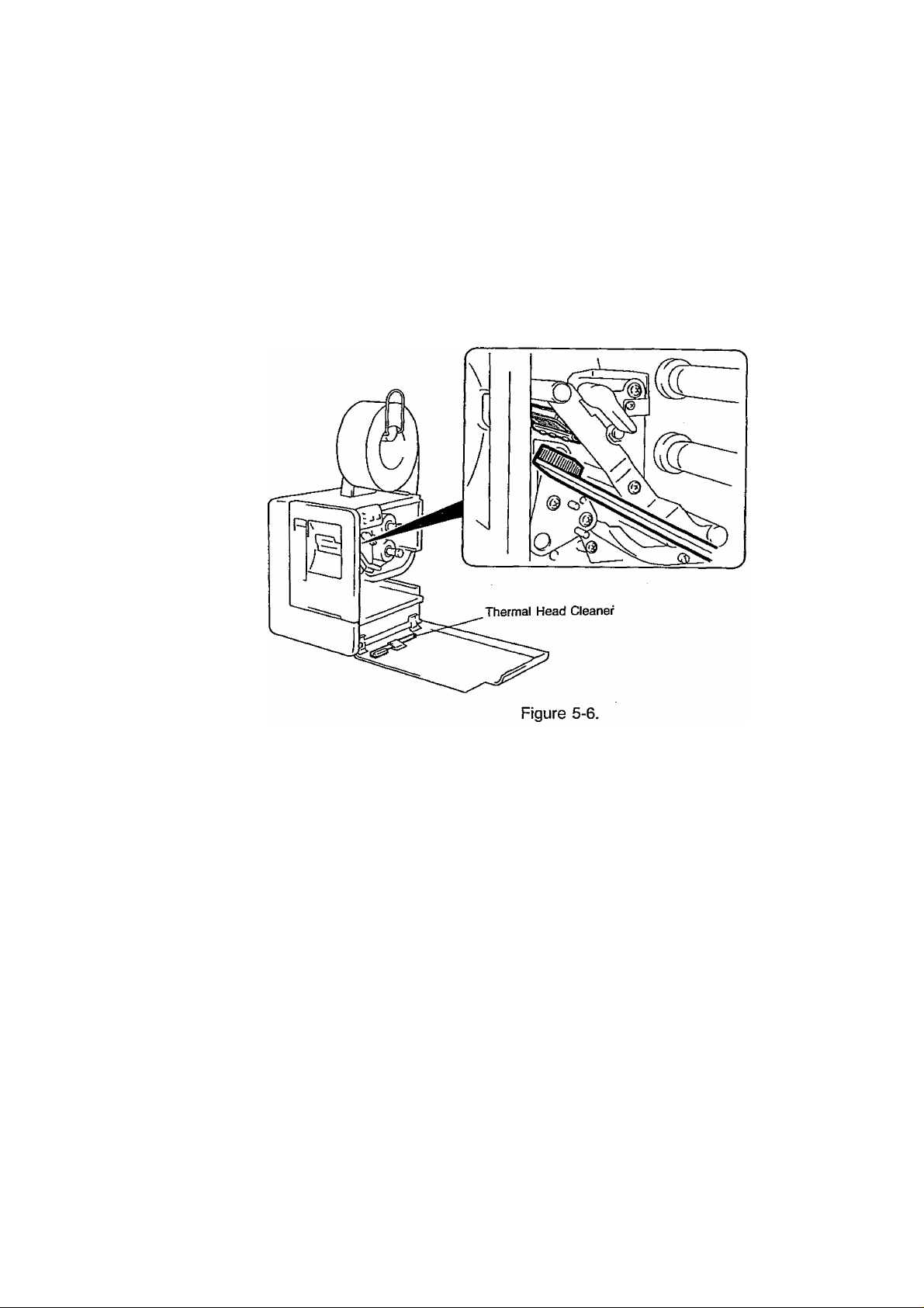
2. CLEANING THE PRINT HEAD
If the print head is dirty, clear printing is not performed.
It is recommended to clean the head with thermal head cleaner before loading a
new ribbon,
1. Turn the power off.
2. Open the front door.
3. Move the head lock lever to the right to release the print head.
4. Remove the ribbon if it has been loaded.
5. Move the supply back past the top of the paper guide.
EM 1-33004
6. Rub back and forth across the print head using thermal head cleaner.
7. Reload the supply and/or ribbon.
WARNING: Turn the power off before cleaning the print head.
WARNING: Be careful NOT TO DAMAGE the print head when cleaning.
5-3
Page 46

EM 1-33004
3. CLEANING THE CUTTER
WARNING: Turn the power off before cleaning the cutter. stationary blade
WARNING: Be extremely careful NOT TO CUT your fingers.
1. Pull out the lock knob and adjustment knob.
2. Pull the upper section of the cutter cover toward
you to remove the cover.
3. Remove screws ® to remove the supply guide
cover.
4. Clean “dust” on the cutter with a soft cloth
moistened with alcohol. Figure 5-7.
WARNING: At this time, DO NOT WIPE OFF the cylinder guides (hatched parts) at both ends of the cutter.
5. If the rotating noise of the blade becomes particularly great, apply grease using
a soft cloth. (Excessively applied grease may stain the supplies.)
Grease should b.e applied to the rotary blade, stationary blade, and cylinder
guides. For the cylinder guides (hatched parts), apply grease to their exposed
parts so that grease spreads all around when the blade turns.
------------------■
i
Cylinder
guide
Rotary blade
‘/M
m
• Cutter Life
Observe raised nap on the cut end of the supply to determine whether the cutter
has worn out. The life of a cutter largely varies according to the material, thickness,
and kind of supply,
ex.)
Good No good
—
Supply
If the cut end of the supply is no longer straight as shown above, contacty your
TEC representative.
5-4
Supply
___
Page 47

4. TROUBLESHOOTING
EM 1-33004
It is our primary concern to give you full satisfaction and better service.
If, however, any problem arises in connection with the operation of this printer, please
check the following points before you call for service.
Error Message
SENSOR OR
LENGTH ERROR
NO PAPER
NO RIBBON
^HEAD OPEN
Problem
1. The paper is not
placed correctly.
2. The feeding paper
is jammed and does
not feed smoothly.
1. Place the paper correctly.
2. Remove the jammed paper
and place the undamaged
paper correctly,
Solution
Press PAUSE key.
-> Press I PAUSE key.
3. The black mark or
feed gap sensor po
3. Adjust the sensor position.
Press j PAUSE key.
sition is incorrect.
4. The combination of
the issuing condi
tion and paper or
sensor does not
4. Select the paper or sensor
matching the issuing con
dition.
Press PAUSE I key.
match.
The supply ran out.
Load a new supply.
Press I PAUSE j kev.
The ribbon ran out. Load a new ribbon.
^ Press PAUSE key.
When the print head is
not set correctly, the
Set the print head correctly.
^ Press PAUSE key.
supply tries to feed or
issue.
CUTTER JAMMED
(for Cutter type only)
1. The paper is not cut
correctly.
1. Set the cutter at the home
position.
^ Press PAUSE key.
2. The supply is jam
med in the cutter
unit.
2. Open the cutter cover and
remove the jammed (block
ing) supply.
“> Press ¡PAUSEI key.
CUTTER COVER
OPEN
(for Cutter type only)
1. The cutter cover is
not closed firmly.
2. The cutter is not at
the home position.
1. Close the cutter cover
securely.
^ Press ! PAUSE key.
2. Set the cutter at the home
position.
-> Press I PAUSE key.
MISSING FEED KEY
ERROR
COMMUNICATION
ERROR
(except for
After replacing with a
new supply, the supply
tries to issue one time
without feeding.
Error has occurred in
communicating with a
personal computer.
Change the issuing condition
for a new supply.
^ Turn off the power and then
turn it on again.
Turn off the power and then
turn it on again.
B-30-S1/H1/C1)
NOTE: When an error is not cleared by pressing the PAUSE! key. turn off the
power and then turn it on again.
When the power is turned on again, print data to be issued is cleared.
5-5
Page 48

EMI-33004
No print.
Problem
1. Check whether the supply or ribbon is loaded correct
Solution
ly or not.
2. Check whether the print head is set correctly or not.
3. Check whether the memory card is inserted correctly
or not.
4. Check whether the interface cable is connected
correctly or not
Printed characters are
unclear (or blurred).
1. Dirty print head. Clean the print head.
2. Bad ribbon. Change to new ribbon.
3. Wrong supply for printing. Change to new supply.
Power is not turned
ON.
1. insert the power plug into the AC outlet firmly.
2. Check the circuit breaker.
3. Check whether the printer fuse is blown or not.
This printer has been manufactured under strict quality control. If you have any
trouble, however, DO NOT ATTEMPT TO FIX IT BY YOURSELF. Turn the power
off, pull the power plug out of the AC outlet, and contact your TEC representative.
5-6
Page 49

(B-30-AU,EU,UK.US)
TOSHIBA TEC CORPORATION
^5:
PRINTED IN JAPAN
m
EM1-33004D ,9404400
 Loading...