

SERVICE MANUAL
FULLY AUTOMATIC
WASHING MACHINE
AW–6'6%2
AW–S'6%$
FILE NO. %-
PRINTED IN THAILAND, -XQ., 20 S
– 1 –
CONTENTS
1. SPECIFICATIONS .................................................................................................................. 1
2. CAUTIONS FOR SAFETY ..................................................................................................... 2
3. CAUTIONS FOR MICROCOMPUTER OPERATION ............................................................. 4
4. TECHNICAL POINT ............................................................................................................... 5
5. INSTALLATION ....................................................................................................................... 8
6. SCHEMATIC DIAGRAM ......................................................................................................... 9
7. CHECKING PROCEDURES ................................................................................................ 10
8. DISASSEMBLY INSTRUCTIONS ......................................................................................... 22
9. CHECK POINTS AFTER REPAIRING ................................................................................. 35
10. EXPLODED VIEWS AND PARTS LIST ................................................................................ 38
1. SPECIFICATIONS
Model
Wash
Spin
Water Level
Water Consumption
Motor Type
Water Pressure
Hot Water
Overall Dimension
Net Weight
Wash
Spin
AW-SD150SBA
50Hz : 70 - 150 rpm
50Hz : 760 rpm
High : 105 L, LOW : L
Regular cycle : 250 L
Capacitor Motor
0.03 ~ 1 Mpa
50 degrees C or less
W: 685 mm x D: 685 mm x H: 1088 mm
50 kg
1.0 kg
Power Source
Plug Type
Wash
Spin
Destination
Specifications are subject to change without notice.
230 - 240 V, 50Hz
33
W
W
Oman
Power Consumption
Revolution
Capacity
AW-SD150SBO
220 V, 50Hz
W
:
UAE
3P
– 2 –
2. CAUTIONS FOR SAFETY
• Please observe the following important notes on safety.
• The notes mean as follows.
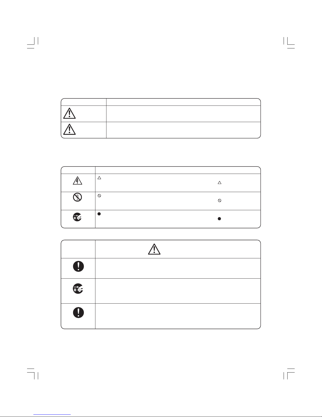
Symbol Meaning
Indicates possibility of death or serious injury of a repair technician and a person
nearby through the misconducted work, or of a user by a defect of the product after
the work performed by the technician.
Indicates possibility of injury or physical damages* of a repair technician and a
person nearby through the misconducted work, or of a user by a defect of the
product after the work performed by the technician.
WARNING
CAUTION
∗ Means secondary damages of property, furniture, domestic animal and pet.
Graphic symbols
Graphic Symbol Meaning
indicates a caution (including a warning).
Specific instruction is followed by a graphic or characters in or near
.
Symbol left warns an electric shock.
indicated prohibition (act must not be conducted).
Specific instruction is followed by a graphic or characters in or near
.
Symbol left warns not to disassemble.
indicates a forcing (act must be conducted).
Specific instruction is followed by a graphic or characters in or near
.
Symbol left warns to unplug the power cord.
ELECTRIC SHOCK
DO NOT
DISASSEMBLE
UNPLUG
L Advise the customer to keep children out of the work place.
Children may be injured with a tool or a disassembled part.
L
Unplug the power cord for the work unnecessary to power on like disassembling.
Do not hold the plug by a wet hand.
Failing to unplug may cause an electric shock.
L Use the specified repair parts when repairing the product.
Otherwise, a malfunction or a defect may occur. Also, a short circuit, ignition or
other danger to the customer may occur.
WARNING
OUT OF CHILD
UNPLUG POWER
USE
REPAIR PARTS
– 3 –
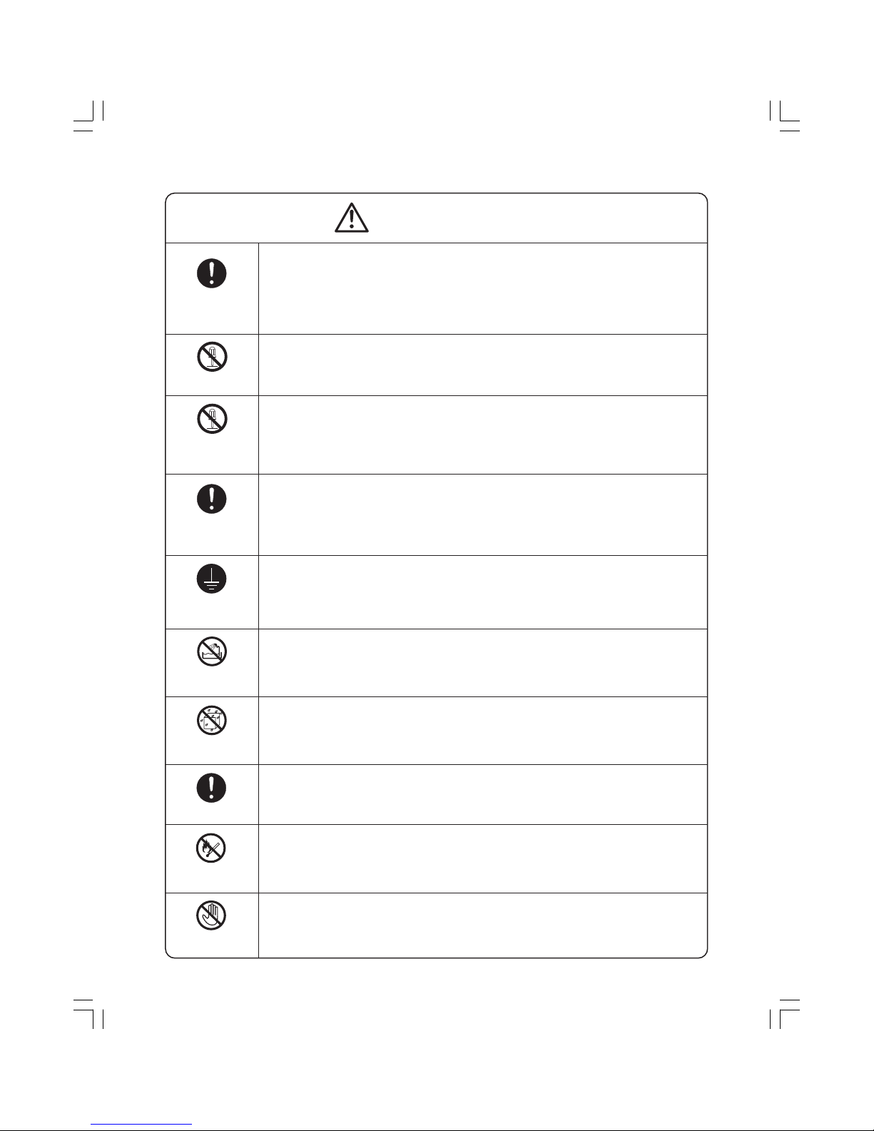
WARNING
L
After the end of working, measure insulation resistance between the charging part
(power cord plug) and the non-charging metallic part (ground) with an insulation
resistance meter (500 V) and check the resistance is 10 MΩ or more.
Failing to check the insulation resistance may cause a short circuit, an electric
shock or other diseases to the customer.
L Do not modify the product.
An electric shock or ignition may occur.
L Only a repair technician can disassemble and repair.
An electric shock, ignition or malfunction may cause injury.
L
Use an exclusive 220 VAC/17 A socket for the washing machine.
Otherwise, an electric shock or ignition may cause. Sharing the same socket with
other instrument causes heating of a branch socket and result in a fire.
L Connect the grounding wire.
Failing to do so may cause an electric shock when a short circuit occurs.
Consult an electric work shop or a sales shop.
L Do not install in a bath room or a place exposed to wind or rain.
An electric shock or a short circuit may cause a fire.
L Do not pour or immerse the electrical parts.
An electric shock or ignition may occur.
L Wipe off the dust adhered to the plug of the power cord.
Dust may cause a fire.
L Do not put inflammable into the washing tub.
Do not put cloths stained with kerosene, gasoline, benzene, thinner, alcohol. etc. It may
causea a fire or explosion.
L Do not touch the laundry before the spin basket stops completely.
The laundry entangles your hand causing an injury even if the basket rotates slowly.
Pay special attention to children.
CHECK INSULATION
RESISTANCE
DO NOT MODIFY
DO NOT
DISASSEMBLE
AND REPAIR
USE EXCLUSIVE
SOCKET
CONNECT
GROUNDING WIRE
DO NOT USE
WET PLACE
DO NOT SPLASH
WATER
REMOVE DUST
DO NOT TOUCH
AVOID INFLAM-
MABLE

– 4 –
CAUTION
L Ask an electric work shop to install the product.
Install the product securely and safely according to the electrical equipment
technical standard and the wiring standard.
Incorrect work causes an electric shock and a fire.
L Do not pull the power cord when unplugging.
Hold the power plug to unplug.
An electric shock or short circuit may cause a fire.
L Do not insert your hand under the washing machine during operation.
There is a rotary part under the machine which may cause an injury.
L Before starting washing, open the faucet and check that the water supply hose
joint is not loose and no water leaks.
The loose screw or hose joint may cause water leakage resulting in an unexpected damage.
INSTALL
CAREFULLY
DO NOT PULL
DANGER HAND
WATER LEAKAGE
3. CAUTIONS FOR MICROCOMPUTER OPERATION
When changing the cycles or procedures of the operation on the way, the operation will not be changed even if
the START/HOLD button is pushed.
When changing the cycles or the procedures of the operation, please turn off the power switch and set them
again.
When the power switch is not turned on, the operation is not performed even if the clock display appears.
(When the clock display appears on the display panel, it may lead misunderstanding to control the operation.
But the operation is not performed in this condition.)
– 5 –
4. Technical Points
One-Point Information
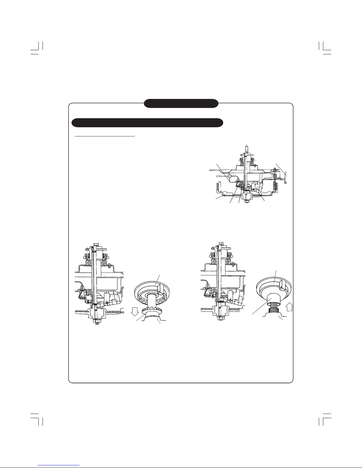
About operation switching by clutch mechanism
1. About Clutch Mechanism
Switch washing operation and spinning operation by
a sliding clutch mechanism. The sliding clutch is
operated by pulling and pushing back the clutch lever.
1) When washing operation is performed, the teeth
on the top of the clutch fit into the teeth of the
lock gear on the upper part of the product
(on cup assy side). Fig.3
2) When spinning operation is performed, the
teeth on the bottom of the clutch fit into the teeth
of the boss on the lower part of the product
(on rotor side). Fig.2
Cup assy Clutch lever
Rotor
Lock gear
Clutch
Switching lever
Fig.1 Clutch mechanism
Lock gear
Clutch
Rotor
Lock gear
Clutch
Rotor
Fig.2 Clutch condition during spinning operation Fig.3 Clutch condition during washing operation
– 6 –
One-Point Information
2. About Operation Switching
Wash A Spin clutch switching
1 Pull the drain valve. (Pull the clutch lever.)
2 The pulsator rotates forwards while repeating small forward and reverse rotations.
3 Clutch switching is completed when both the wash tub and the pulsator start rotating.
In the case where the clutch is not switched even after the clutch switching is attempted 4 times, fill the
wash tub with water again and fluff the laundry, then perform the same switching operation. If the clutch is
still not switched, the error Ec6 is displayed.
Sometimes, clutch switching operation is performed by filling the wash tub with water at the start of
spinning.
(See Page 2 for details of Ec errors.)
Spin A Wash clutch switching
1 The drain valve returns. (The lever returns.)
2 Spin tub makes small forward and reverse rotations.
3 The spin tub makes large forward and reverse rotations at a low speed.
4 Clutch switching is completed when only the pulsator starts rotating.
In the case where the clutch is not switched even after the clutch switching is attempted 6 times, fill the
wash tub with water and let it stand for 3 minutes, then perform the switching operation again. If the
clutch is still not switched, rotate the wash tub by 180 degrees and perform the same switching operation.
If the clutch is still not switched, the error Ec5 is displayed. (See Page 2 for details of Ec errors.)
Note) If the washing operation was originally being performed, the clutch switching is not performed but
the washing operation starts immediately.
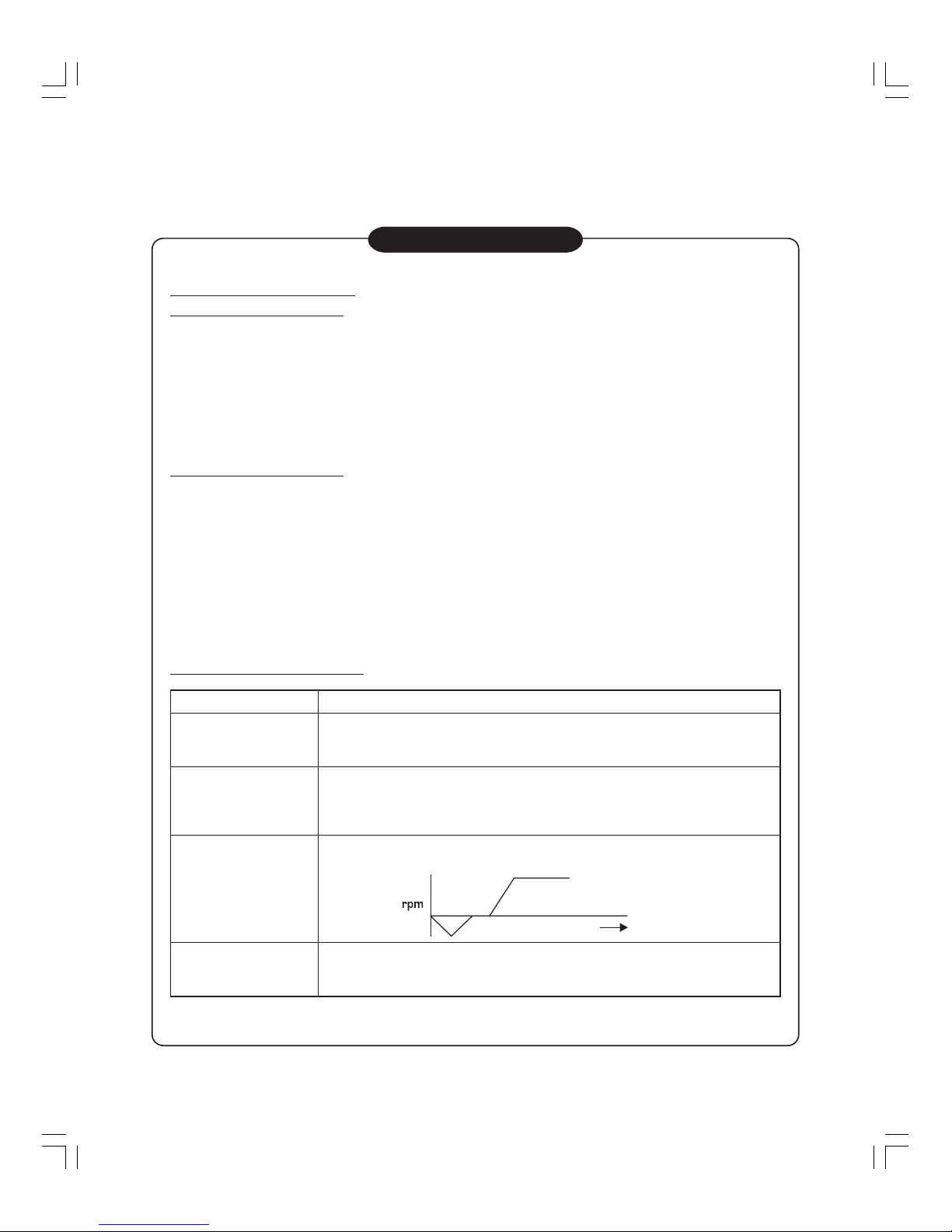
3. About operation of wash tub
When the power is
turned off during spin
process
Operation
Just as the current models, the wash tub does not rotate even if it is not turned
clockwise or counterclockwise direction. The wash tub stops at multiple
positions (at one of the 18 points for every 20 degrees)
Just as the current models, the wash tub rotates freely both in clockwise or
counterclockwise direction. When a long time (30 minutes) has elapsed, the
machine is switched to the clutch switching standby status.
After rotating in the reverse direction at the start of spinning, the main spinning
is performed. (This control is adopted from E-series.)
Just as the current models, brake is applied to stop rotation. When the rotation
stops, the clutch lever returns and the machine is switched to the clutch
switching standby status.
Process
Wash process & when
wash process is stopped
When spin process is
suspended.
(When the lid is opened
during spin process)
At the start of spinning
Forward rotation
Reverse rotation
Time
– 7 –
One-Point Information
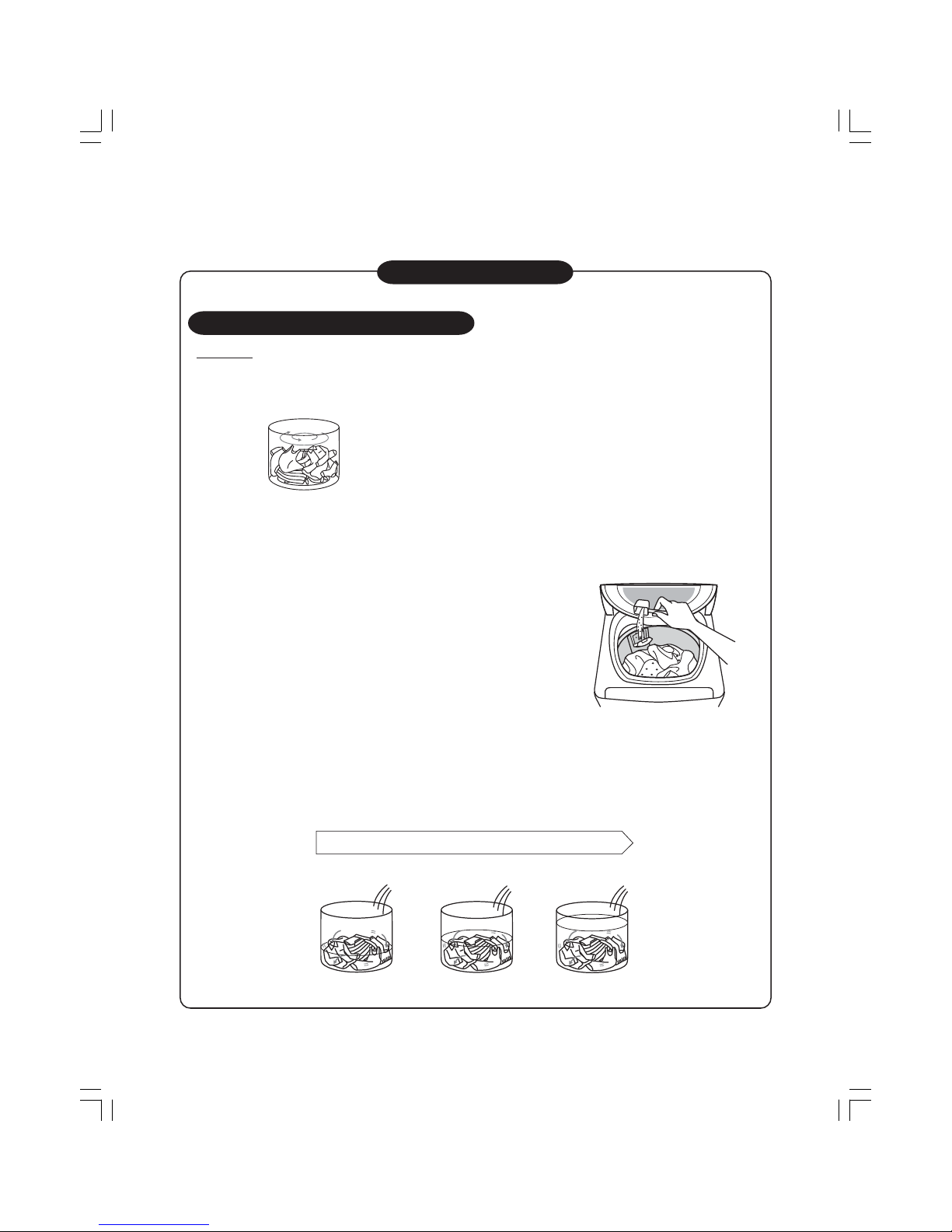
About Concentrated Bubble Wash
1. Outline
Put the laundry in the basket and start the machine. The sensor will weigh clothes and begin flowing water.
1
The pulsator begins to revolve 6 seconds after startup under none-water situation, and clothes are
weighed.
2
)ORwing water starts. Put in detergent accorGLQJWRWKHUHIHUHQFHYDOXHWKURXJKHQWU\JDWHRI
"Washing Spinning Tub", followed by softening agent. Close the lid. Display of detergent amount.
■ How to put detergent
Referring to the indicated detergent amount, put the
detergent into the detergent dispenser of the wash/spin tub.
Excessive detergent may lead to excessive suds or
insufficient rinsing.
If the water level is set to too low, some detergent may be
left in the dispenser.
In this case, put the detergent inside the wash/spin tub
around its peripheral.
∗ There are 2 dispensers.
Choose more convenient one to put in the detergent.
• When changing the dispenser position
Turn on the power, set spin only while the lid is open, and then start the machine.
After “E21” is displayed, rotate the wash/spin tub manually to adjust the dispenser position. Then,
turn off the power.
3
The water level indicator will be lighted when flowing water ends by reaching the preset water level.
• When a chemical fiber, blending fiber or spreadsheet is washed, the water level may be a little bit low.
Adjust the water level by "WATER LEVEL" button.
Stirring starts during flowing water while washing and flowing water are executed simultaneously.
Times of flowing water differ depending onFORWKHVZHLJKWDQGULQVLQJIUHTXHQF\
Washinging
Stirring during
flowing water
Stirring during
flowing water
Stirring during
flowing water
– 8 –
One-Point Information
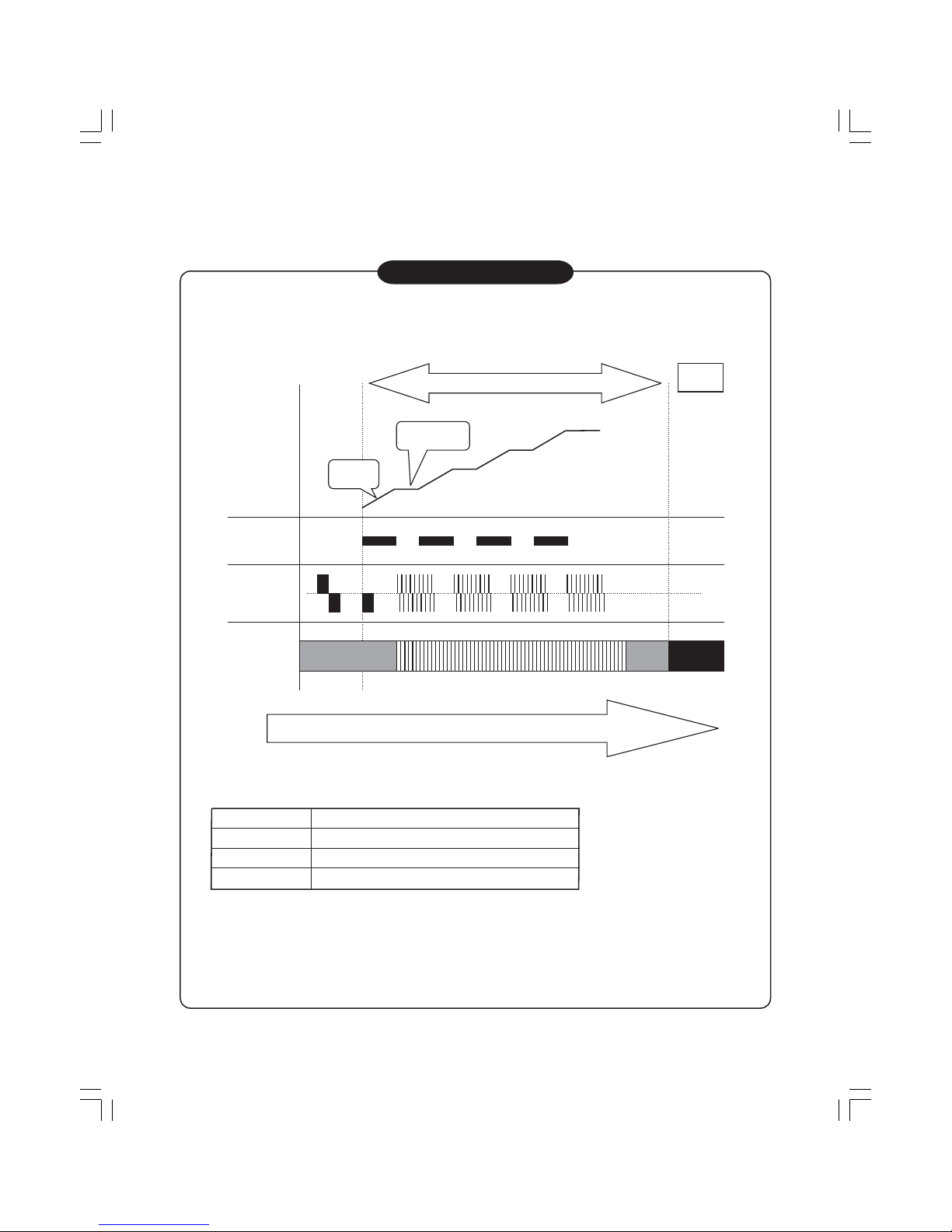
2. Operation Cycle
Example : At high water level
High
Water level
Low
Water
supply valve
Motor
Concentrated
Bubble
Cleaning
Indicator
Weight
sensor
Wash Process
Drain
Agitation
Water
supply
Light Flash Light Off
Time scale
Washing load Number of levels of water supply and agitation
8.1 kg and above
1.1 ~ 8.0 kg 3 levels
Below 1.0 kg 2 levels
Number of levels of water supply and agitation vary depending on the washing load.
∗ When increasing the number of rinsing for the reason that the tub has already been filled with water,
the above number of levels may become less.
∗ Agitation varies depending on the washing load
∗ If washing time (preset: 15 minutes) is changed in the midst of wash process, agitating time in each level
becomes shorter.
4 levels
– 9 –
One-Point Information
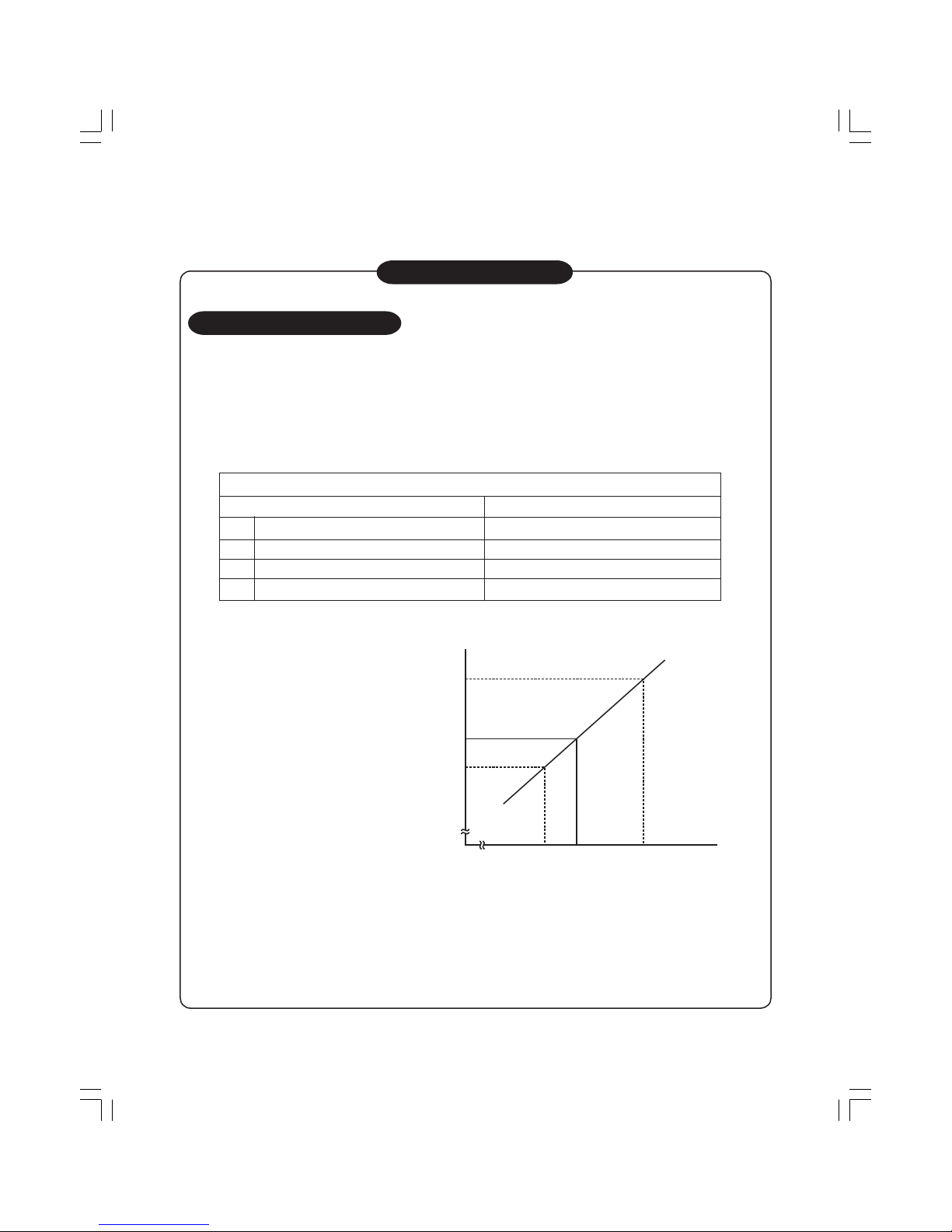
About Linear Water Level
When “Standard”, “Soak” , “Memory”,"Heavy","Delicate" or "Softener" is set, the weight sensor automatically
sets the most suitable water level for the washing load on a linear basis to save water.
Setting is made based on the 4-levelled water level for manual setting. For example, when the detected
washing load is 5.0kg, the most suitable water level of 67.3L is automatically set by proportional calculation
between the first level of 82L for washing load of 7.0kg and the second level of 60L for washing load of
4.0kg. The display indicator for the lower water level, i.e., 60L for this example, turns on.
Manually set water level
1
2
82L
7.0Kg
3
60L
4.0Kg
4
36L
1.0Kg
2
.
4.0
5..
(L)
(KL)
Water level
Washing load
Water level of 36L is very low as the blade of the pulsator is not fully covered with water. However, this water
level is suitable for washing the washing load of 1.0kg or below.
It is not an abnormal level.
AW-SD1567\SH
1.0Kg
105L
Washing load
– 10 –
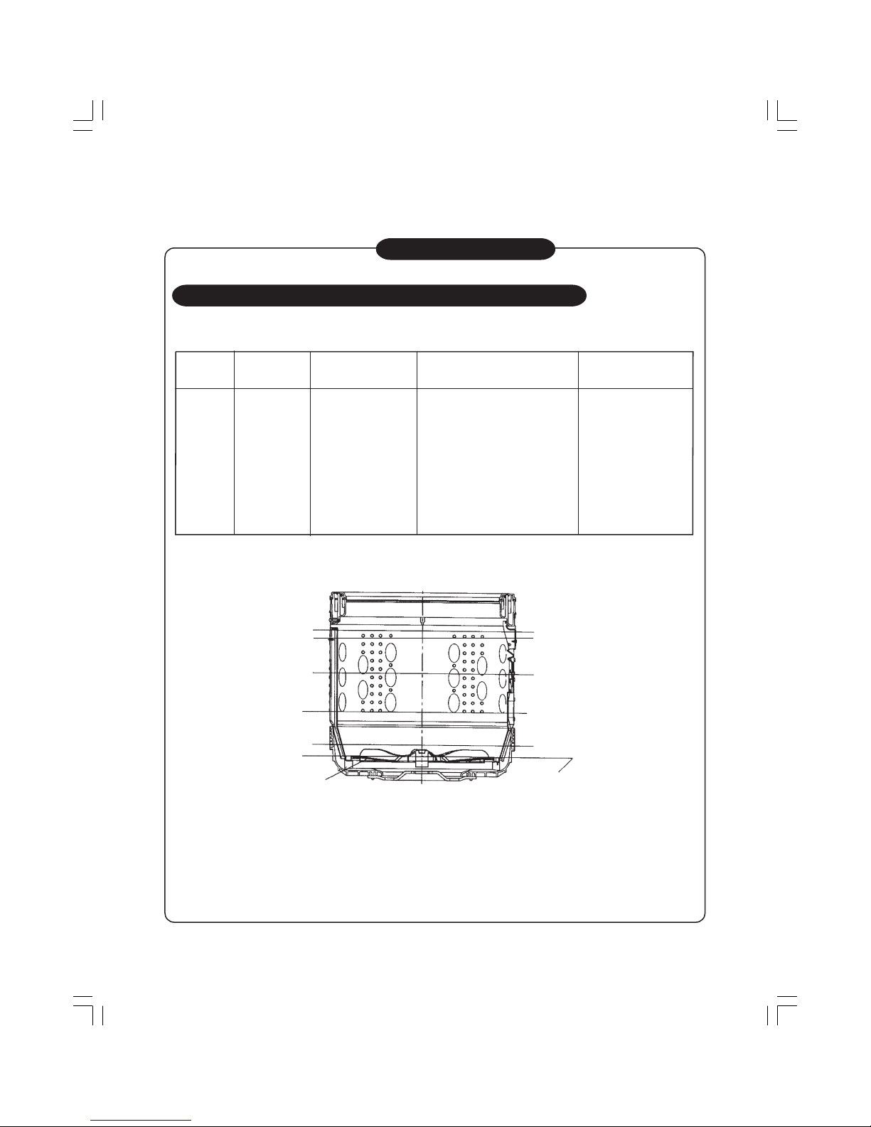
One-Point Information
Relation between oscillation frequency and water level
The table below shows the relation between oscillation frequency and water level.
Water level Water amount Oscillation frequency
Distance from the top edge of the
Reference water level
outer periphery of the pulsator
–
26.40kHz and above
––
– 26.05kHz – –
36L 25.10kHz 100±30 mm
60L 23.80kHz
82L 23.00kHz
100L 22.05kHz
No water
reset
Low 60L
Pulsator
High 105L
Med 82L
Very little 36L
End of the outer
periphery of the pulsator
<Reference Water Level>
105L 22.00kHz
High 100L
±
30 mm
±
30 mm
5HIHUWRWKHILJXUHEHORZ
±
15 mm
±
15 mm
㩷㩷㪚㫆㫌㫉㫊㪼
㪮㪸㫋㪼㫉
㫃㪼㫍㪼㫃
㪁㪥㫆㫋㪼㪈
㪮㪼㫀㪾㪿㫋㩷㪻㪼㫋㪼㪺㫋㫀㫆㫅
㪮㪸㫋㪼㫉㩷㫊㫌㫇㫇㫃㫐
㪧㫉㪼㪄㪸㪾㫀㫋㪸㫋㫀㫆㫅
㪮㪸㫊㪿
㪩㪸㫍㪼㫃
㪛㫉㪸㫀㫅
㪪㫇㫀㫅
㪪㫋㫆㫇
㪙㫉㪸㫂㪼
㪮㪸㫋㪼㫉㩷㪽㫀㫃㫃㫀㫅㪾
㪪㫇㫀㫅
㪪㫋㫆㫇
㪙㫉㪸㫂㪼
㪮㪸㫋㪼㫉㩷㪽㫀㫃㫃㫀㫅㪾
㪪㫇㫀㫅
㪪㫋㫆㫇
㪙㫉㪸㫂㪼
㪮㪸㫋㪼㫉㩷㫊㫌㫇㫇㫃㫐
㪧㫉㪼㪄㪸㪾㫀㫋㪸㫋㫀㫆㫅
㪩㫀㫅㫊㪼
㪩㪸㫍㪼㫃
㪛㫉㪸㫀㫅
㪪㫇㫀㫅
㪪㫋㫆㫇
㪮㪸㫋㪼㫉㩷㫊㫌㫇㫇㫃㫐
㪧㫉㪼㪄㪸㪾㫀㫋㪸㫋㫀㫆㫅
㪩㫀㫅㫊㪼
㪩㪸㫍㪼㫃
㪛㫉㪸㫀㫅
㪪㫇㫀㫅
㪪㫋㫆㫇
㪙㫌㫑㫑㪼㫉
㪣㫀㫅㪼㪸㫉
㪸㫌㫋㫆㩷㫊㪼㫋㫋㫀㫅㪾
㩿㪊㪍㪣䌾㪈㪇㪌㪣㪀
䋨㪟㫀㪾㪿㩷㫎㪸㫋㪼㫉㩷㫃㪼㫍㪼㫃㩷㪺㫆㫅㪻㫀㫋㫀㫆㫅㩷㪀
㪣㫀㫅㪼㪸㫉
㪮㪸㫊㪿
㪸㫌㫋㫆㩷㫊㪼㫋㫋㫀㫅㪾
㩿㪊㪍㪣䌾㪈㪇㪌㪣㪀
㪣㫀㫅㪼㪸㫉
㪩㫀㫅㫊㪼
㪸㫌㫋㫆㩷㫊㪼㫋㫋㫀㫅㪾
㫆㫅㪼
㩿㪊㪍㪣䌾㪈㪇㪌㪣㪀
㫋㫀㫄㪼 㪁㪥㫆㫋㪼㪉
㪣㫀㫅㪼㪸㫉
㪩㫀㫅㫊㪼
㪸㫌㫋㫆㩷㫊㪼㫋㫋㫀㫅㪾
㫋㫎㫆
㩿㪊㪍㪣䌾㪈㪇㪌㪣㪀
㫋㫀㫄㪼㫊 㪁㪥㫆㫋㪼㪉
㪣㫀㫅㪼㪸㫉
㪩㫀㫅㫊㪼
㪸㫌㫋㫆㩷㫊㪼㫋㫋㫀㫅㪾
㫋㪿㫉㪼㪼
㩿㪊㪍㪣䌾㪈㪇㪌㪣㪀
㫋㫀㫄㪼㫊 㪁㪥㫆㫋㪼㪉
㪣㫀㫅㪼㪸㫉
㪩㫀㫅㫊㪼
㪸㫌㫋㫆㩷㫊㪼㫋㫋㫀㫅㪾
㪽㫆㫌㫉
㩿㪊㪍㪣䌾㪈㪇㪌㪣㪀
㫋㫀㫄㪼㫊 㪁㪥㫆㫋㪼㪉
㪪㫇㫀㫅 㫅㫀㫃
㫊㫋㪸㫋㫀㪺㩷㫉㫀㫅㫊㪼㩷 㩷㫊㫋㪸㫋㫀㪺㩷㫉㫀㫅㫊㪼㩷
㩿㫊㫌㫇㫇㫃㪼㫄㪼㫅㫋㪸㫃㫐㩷 㫆㫍㪼㫉㩷㪽㫃㫆㫎㩷㫉㫀㫅㫊㪼 㫆㫍㪼㫉㩷㪽㫃㫆㫎㩷㫉㫀㫅㫊㪼
㩷㩷㫎㪸㫋㪼㫉㩷㪽㫀㫃㫃㫀㫅㪾㪀
㪝㫆㫉㫎㪸㫉㪻
㫉㫆㫋㪸㫋㫀㫆㫅
㩿㩷㪚㪚㪮㪀
㪩㪼㫍㪼㫉㫊㪼
㫉㫆㫋㪸㫋㫀㫆㫅
㩿㩷㪚㪮㪀
㪥㫆㫋㪼㪈㩷㪑
㪥㫆㫋㪼䋲㩷㪑 㪮㪿㪼㫅㩷㩹㪮㪸㫊㪿㩹㩷㫀㫊㩷㫅㫆㫋㩷㫊㪼㫋㩷㪃㩷㫋㪿㪼㩷㫎㪸㫋㪼㫉㩷㫃㪼㫍㪼㫃㩷㫎㫀㫃㫃㩷㪸㫌㫋㫆㫄㪸㫋㫀㪺㪸㫃㫃㫐㩷㪹㪼㩷㫊㪼㫋㩷㫋㫆㩷㪿㫀㪾㪿㪅
䊶䇭㪠㫅㩷㫋㪿㪼㩷㪺㪸㫊㪼㩷㫎㪿㪼㫉㪼㩷㫋㪿㪼㩷㫇㫆㫎㪼㫉㩷㫀㫊㩷㫋㫌㫉㫅㪼㪻㩷㫆㫅㩷㩿㩷㫋㪿㪼㩷㫇㫆㫎㪼㫉㩷㪹㫌㫋㫋㫆㫅㩷㫀㫊㩷㫇㫉㪼㫊㫊㪼㪻㩷㪀㩷㪹㫌㫋㩷㫅㫆㩷㫆 㫇㪼㫉㪽㫆㫉㫄㪼㪻㪃㩷㫋㪿㪼㩷㫇㫆㫎㪼㫉㩷㫀㫊㩷㫋㫌㫉㫅㪼㪻㩷㫆㪽㪽㩷㫀㫅㩷㪈㪇㩷㫄㫀㫅㫌㫋㪼㫊㪅
㪣㫀㪻㩷㪣㫆㪺㫂
㪦㫌㫋㫆㫌㫋
㪪㫆㪽㫋㪼㫅㪼㫉㩷㫎㪸㫋㪼㫉
㫊㫌㫇㫇㫃㫐㩷㫍㪸㫃㫍㪼
㪤㫆㫋㫆㫉
㪛㫉㪸㫀㫅㩷㫍㪸㫃㫍㪼
㪪㫋㪸㫋㫀㪺㩷㫉㫀㫅㫊㪼㩷㪈 㪪㫋㪸㫋㫀㪺㩷㫉㫀㫅㫊㪼㩷㪉
㪩㫀㫅㫊㪼 㪪㫇㫀㫅
㪮㪸㫋㪼㫉㩷㪽㫃㫆㫎㩷㪻㪼㫋㪼㪺㫋㫀㫆㫅
㪮㪸㫊㪿
㪪㪿㫆㫎㪼㫉㩷㫉㫀㫅㫊㪼㩷㪈 㪪㪿㫆㫎㪼㫉㩷㫉㫀㫅㫊㪼㩷㪉
㪚㫆㫅㪻㪼㫅㫊㪼㪻
㪩㪼㪾㫌㫃㪸㫉
㪤㪼㫄㫆㫉㫐
㪮㪸㫋㪼㫉㩷㫊㫌㫇㫇㫃㫐㩷㫍㪸㫃㫍㪼
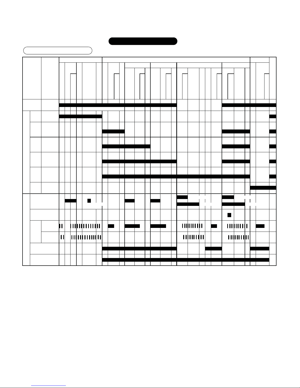
㪦㫅㪼㪄㪧㫆㫀㫅㫋㩷㩷㪠㫅㪽㫆㫉㫄㪸㫋㫀㫆㫅
㪮㪸㫊㪿㫀㫅㪾㩷㪧㫉㫆㪺㪼㫊㫊㩷㪚㪿㪸㫉㫋
– 11 –
AW-SD150S Type 36L ~ 105L
peration is
㩷㩷㪚㫆㫌㫉㫊㪼
㪮㪸㫋㪼㫉
㫃㪼㫍㪼㫃
㪮㪼㫀㪾㪿㫋㩷㪻㪼㫋㪼㪺㫋㫀㫆㫅
㪮㪸㫋㪼㫉㩷㫊㫌㫇㫇㫃㫐
㪧㫉㪼㪄㪸㪾㫀㫋㪸㫋㫀㫆㫅
㪪㫆㪸㫂
㪩㪸㫍㪼㫃
㪛㫉㪸㫀㫅
㪪㫇㫀㫅
㪪㫋㫆㫇
㪙㫉㪸㫂㪼
㪮㪸㫋㪼㫉㩷㪽㫀㫃㫃㫀㫅㪾
㪪㫇㫀㫅
㪪㫋㫆㫇
㪙㫉㪸㫂㪼
㪮㪸㫋㪼㫉㩷㪽㫀㫃㫃㫀㫅㪾
㪪㫇㫀㫅
㪪㫋㫆㫇
㪙㫉㪸㫂㪼
㪮㪸㫋㪼㫉㩷㫊㫌㫇㫇㫃㫐
㪧㫉㪼㪄㪸㪾㫀㫋㪸㫋㫀㫆㫅
㪩㫀㫅㫊㪼
㪩㪸㫍㪼㫃
㪛㫉㪸㫀㫅
㪪㫇㫀㫅
㪪㫋㫆㫇
㪮㪸㫋㪼㫉㩷㫊㫌㫇㫇㫃㫐
㪧㫉㪼㪄㪸㪾㫀㫋㪸㫋㫀㫆㫅
㪩㫀㫅㫊㪼
㪩㪸㫍㪼㫃
㪛㫉㪸㫀㫅
㪪㫇㫀㫅
㪪㫋㫆㫇
㪙㫌㫑㫑㪼㫉
㪣㫀㫅㪼㪸㫉
㪸㫌㫋㫆㩷㫊㪼㫋㫋㫀㫅㪾
㩿㪊㪍㪣䌾㪈㪇㪌㪣㪀
䋨㪟㫀㪾㪿㩷㫎㪸㫋㪼㫉㩷㫃㪼㫍㪼㫃㩷㪺㫆㫅㪻㫀㫋㫀㫆㫅㩷㪀
㪣㫀㫅㪼㪸㫉
㩿㫆㫍㪼㫉㩷㪽㫃㫆㫎㩷㫉㫀㫅㫊㪼㪀 㩿㫆㫍㪼㫉㩷㪽㫃㫆㫎㩷㫉㫀㫅㫊㪼㪀
㪸㫌㫋㫆㩷㫊㪼㫋㫋㫀㫅㪾
㩿㪊㪍㪣䌾㪈㪇㪌㪣㪀
䋨㪟㫀㪾㪿㩷㫎㪸㫋㪼㫉㩷㫃㪼㫍㪼㫃㩷㪺㫆㫅㪻㫀㫋㫀㫆㫅㩷㪀
㪣㫀㫅㪼㪸㫉
㩿㪍㩷㫄㫀㫅㪀 㩿㪌㩷㫄㫀㫅㪀
㪸㫌㫋㫆㩷㫊㪼㫋㫋㫀㫅㪾
㩿㪊㪍㪣䌾㪈㪇㪌㪣㪀
䋨㪟㫀㪾㪿㩷㫎㪸㫋㪼㫉㩷㫃㪼㫍㪼㫃㩷㪺㫆㫅㪻㫀㫋㫀㫆㫅㩷㪀
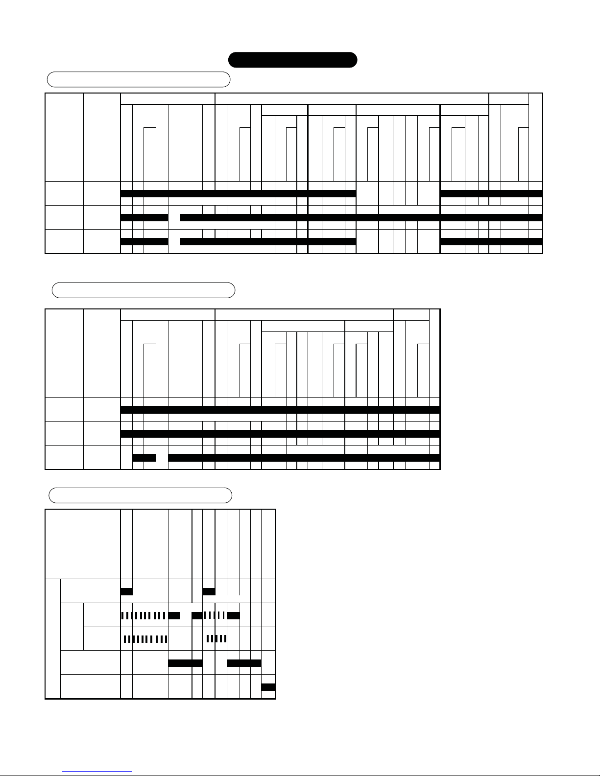
㩷㩷㪚㫆㫌㫉㫊㪼
㪮㪸㫋㪼㫉
㫃㪼㫍㪼㫃
㪮㪼㫀㪾㪿㫋㩷㪻㪼㫋㪼㪺㫋㫀㫆㫅
㪮㪸㫋㪼㫉㩷㫊㫌㫇㫇㫃㫐
㪧㫉㪼㪄㪸㪾㫀㫋㪸㫋㫀㫆㫅
㪮㪸㫊㪿
㪩㪸㫍㪼㫃
㪛㫉㪸㫀㫅
㪪㫇㫀㫅
㪪㫋㫆㫇
㪙㫉㪸㫂㪼
㪮㪸㫋㪼㫉㩷㫊㫌㫇㫇㫃㫐
㪧㫉㪼㪄㪸㪾㫀㫋㪸㫋㫀㫆㫅
㪩㫀㫅㫊㪼
㪩㪸㫍㪼㫃
㪛㫉㪸㫀㫅
㪪㫇㫀㫅
㪪㫋㫆㫇
㪮㪸㫋㪼㫉㩷㫊㫌㫇㫇㫃㫐
㪧㫉㪼㪄㪸㪾㫀㫋㪸㫋㫀㫆㫅
㪩㫀㫅㫊㪼
㪩㪸㫍㪼㫃
㪛㫉㪸㫀㫅
㪪㫇㫀㫅
㪪㫋㫆㫇
㪙㫌㫑㫑㪼㫉
㪣㫀㫅㪼㪸㫉
㪸㫌㫋㫆㩷㫊㪼㫋㫋㫀㫅㪾
㩿㪊㪍㪣䌾㪈㪇㪌㪣㪀
䋨㪟㫀㪾㪿㩷㫎㪸㫋㪼㫉㩷㫃㪼㫍㪼㫃㩷㪺㫆㫅㪻㫀㫋㫀㫆㫅㩷㪀
㪣㫀㫅㪼㪸㫉
㩿㪍㩷㫄㫀㫅㪀 㩿㪊㩷㫄㫀㫅㪀
㪸㫌㫋㫆㩷㫊㪼㫋㫋㫀㫅㪾
㩿㪊㪍㪣䌾㪍㪇㪣㪀
㩿㫆㫍㪼㫉㩷㪽㫃㫆㫎㩷㫉㫀㫅㫊㪼㪀 㩿㫆㫍㪼㫉㩷㪽㫃㫆㫎㩷㫉㫀㫅㫊㪼㪀
㪈㪇㪌㪣
㪮㪸㫋㪼㫉㩷㫊㫌㫇㫇㫃㫐
㪮㪸㫊㪿
㪪㫇㫀㫅㩷㩷㩷㫉㪼㫄㪸㫀㫅㫀㫅㪾㩷㫎㪸㫋㪼㫉
㪛㫉㪸㫀㫅
㪪㫇㫀㫅
㪮㪸㫋㪼㫉㩷㫊㫌㫇㫇㫃㫐
㪩㫀㫅㫊㪼
㪪㫇㫀㫅㩷㩷㩷㫉㪼㫄㪸㫀㫅㫀㫅㪾㩷㫎㪸㫋㪼㫉
㪛㫉㪸㫀㫅
㪪㫇㫀㫅
㪙㫌㫑㫑㪼㫉
㪮㪸㫋㪼㫉㩷㫊㫌㫇㫇㫃㫐㩷㫍㪸㫃㫍㪼
㩿㪟㫀㪾㪿㩷㪂㩷㪊㪇㩷㫊㪼㪺㪀 㩿㪟㫀㪾㪿㩷㪂㩷㪊㪇㩷㫊㪼㪺㪀
㪝㫆㫉㫎㪸㫉㪻 㩿㪍㩷㫄㫀㫅㪀
㫉㫆㫋㪸㫋㫀㫆㫅
㩿㩷㪚㪚㪮㪀
㪩㪼㫍㪼㫉㫊㪼
㫉㫆㫋㪸㫋㫀㫆㫅
㩿㩷㪚㪮㪀
㪛㫉㪸㫀㫅㩷㫍㪸㫃㫍㪼
㪘㫌㫋㫆㩷
㫇
㫆㫎㪼㫉㩷㫆㪽㪽
㪪㫋㪸㫋㫀㪺㩷㫉㫀㫅㫊㪼㩷㪈 㪪㫋㪸㫋㫀㪺㩷㫉㫀㫅㫊㪼㩷㪉
㪩㫀㫅㫊㪼 㪪㫇㫀㫅㪮㪸㫊㪿
㪪㪿㫆㫎㪼㫉㩷㫉㫀㫅㫊㪼㩷㪈 㪪㪿㫆㫎㪼㫉㩷㫉㫀㫅㫊㪼㩷㪉
㪮㪸㫊㪿
㪛㪼㫃㫀㪺㪸㫋㪼
㪪㫇㪼㪼㪻
㪮㪸㫋㪼㫉㩷㪽㫃㫆㫎㩷㪻㪼㫋㪼㪺㫋㫀㫆㫅
㪪㫆㪸㫂
㪟㪼㪸㫍㫐㩷㫎㪸㫊㪿
㪮㪸㫊㪿 㪪㫇㫀㫅
㪪㫋㪸㫋㫀㪺㩷㫉㫀㫅㫊㪼㩷㪈 㪪㫋㪸㫋㫀㪺㩷㫉㫀㫅㫊㪼㩷㪉
㪤㫆㫋㫆㫉
㪪㫆㪸㫂
㪦㫌㫋㫇㫌㫋
㪩㫀㫅㫊㪼
㪙㫃㪸㫅㫂㪼㫋
㪮㪸㫋㪼㫉㩷㪽㫃㫆㫎㩷㪻㪼㫋㪼㪺㫋㫀㫆㫅
㪪㫆㪽㫋㪼㫅㪼㫉
㪦㫅㪼㪄㪧㫆㫀㫅㫋㩷㩷㪠㫅㪽㫆㫉㫄㪸㫋㫀㫆㫅
㪪㫆㪸㫂㩷䊶㩷㪟㪼㪸㫍㫐㩷㫎㪸㫊㪿㩷䊶㩷㪛㪼㫃㫀㪺㪸㫋㪼㩷㩷㪚㫆㫌㫉㫊㪼
㪪㫆㪽㫋㪼㫅㪼㫉㩷䊶㩷㪪㫇㪼㪼㪻㩷䊶㩷㪙㫃㪸㫅㫂㪼㫋㩷㪚㫆㫌㫉㫊㪼
㪫㫌㪹㩷㪚㫃㪼㪸㫅㫀㫅㪾㩷㩷㪚㫆㫌㫉㫊㪼
– 12 –
Through setting of the SUPER SPIN DRY for 30 minutes, you can vapor the water contained in clothes, thus shorten
their indoor drying time. In addition, you can basically dry sports wear, chemical fiber or blending fiber by setting
SUPER SPIN DRY for 60 minutes (less than 3 kg).
• The hand touch differs depending on the type, weight of clothes, room temperature and moisture. Clothes will be cold due to air
drying process, so they may produce a hand touch feeling like the wet ones.
When you need to dry clothes or shorten their indoor drying time.
SUPER SPIN DRY
1 time
2 times
3 times
4 times
5 times
6 times
“REGULAR” course for CONDENSED BUBBLE
“REGULAR” course for CONDENSED BUBBLE
“REGULAR” course for CONDENSED BUBBLE
None
None
None
30 minutes
60 minutes
90 minutes
30 minutes
60 minutes
90 minutes
Washing SUPER SPIN DRY
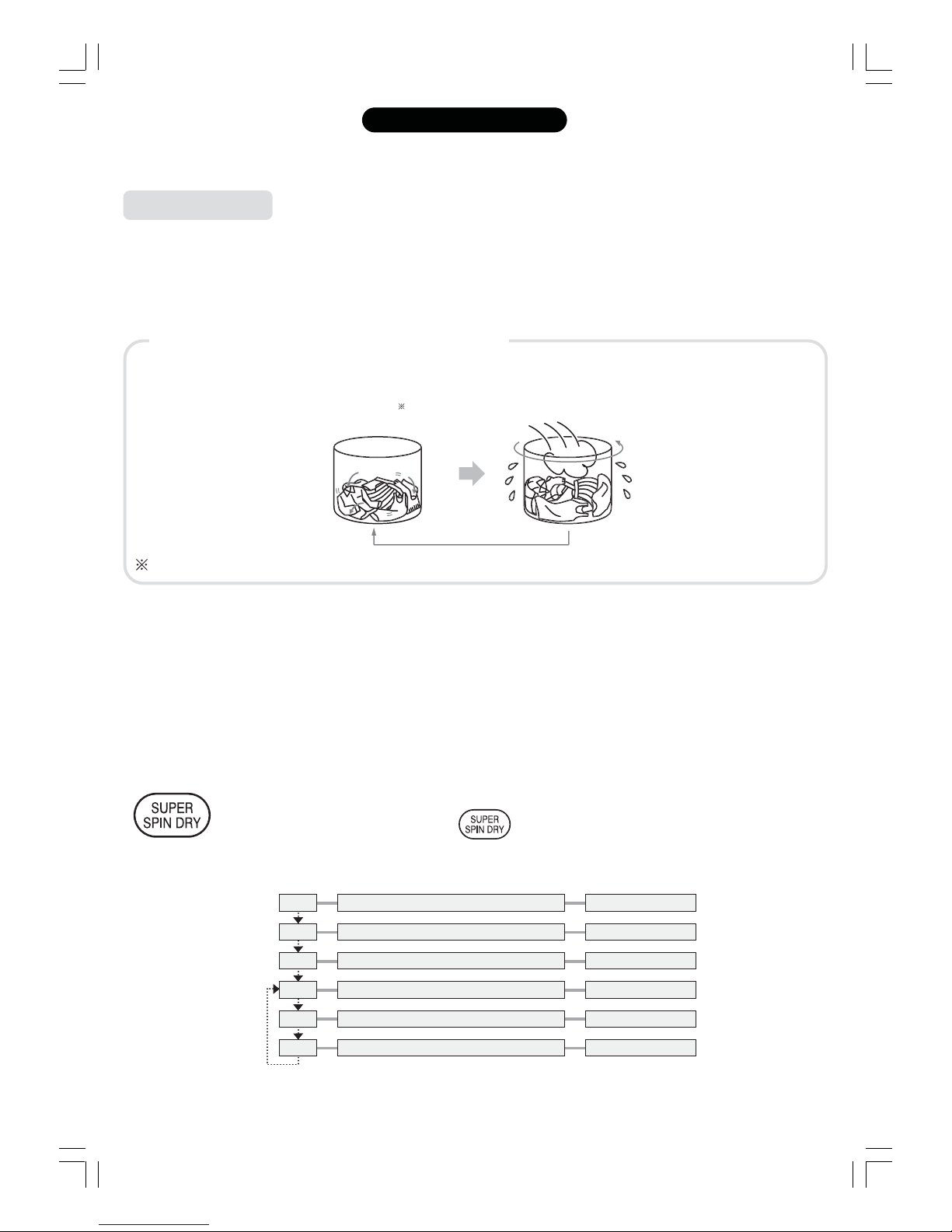
What is the SUPER SPIN DRY?
This is a course which discharge wet air through the high-speed revolving of the washing-spinning tub, thus
vapor the water carried by the clothes.
Stirring High-speed revolving
Repeatedly
: Stir for every 15 minutes to unravel the clothes. Stirring may not be necessary, depending on the weight of the clothes.
LClothes prohibited for the SUPER SPIN DRY
• Since the SUPER SPIN DRY needs a long time for high-speed revolving, and unravel clothes every 15 minutes,
the following articles are not allowed for the process:
• Clothes with unstable color
• Creasing-prone clothes (such as frock, or 100% cotton shirt)
• Deformation-prone clothes
• Water-tight clothes
• Quilt and blanket
LMethod of using SUPER SPIN DRY button
(Ex.) When the “REGULAR” course of the “CONDENSED BUBBLE” is being executed
Press the “SUPER SPIN DRY” to select processing time according to the following sequence or select
SUPER SPIN DRY only. Please press the
button for at least 4 times, when you select
SUPER SPIN DRY only.
SUPER SPIN DRY
– 13 –
One-Point Information
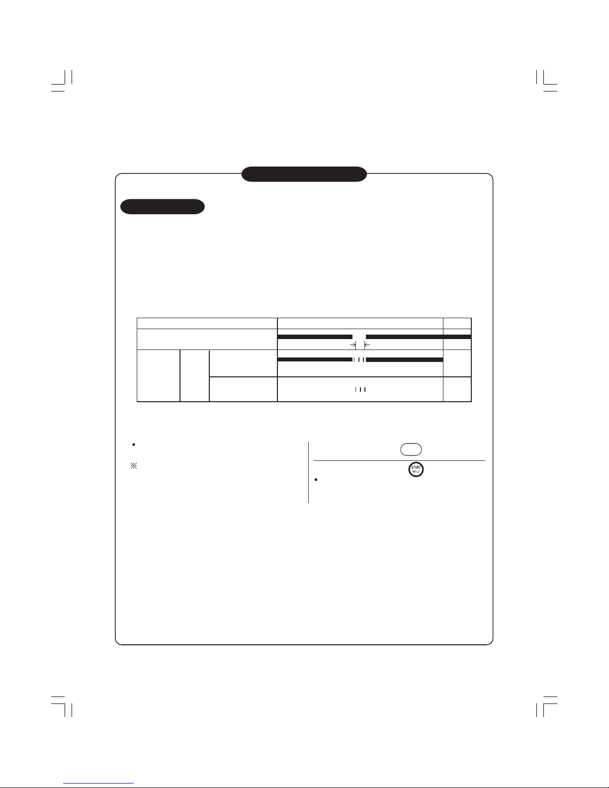
About Tub Dry
1. O utline
B y pe rforming "tub dry" ope ra tion after w as hing is c omple ted, humidity inside the was h/spin tub ca n be
removed a nd growth of black mold c a n be reduced.
2. P rocess
Dry u p th e rema ini ng wa te r by high- s pee d ro ta tion of wa s h/s pin tub for a pp roxima te ly 3 0 minute s .
P e rfor m this o pe r a tion a fte r re mo ving a ll the c lo the s in the tub to e mpty the tub.
3. P a ne l ope ra tion
Tub rota tion a t h ig h s peed(30 min)
Forward
ro ta tion
Motor
Reverse
ro ta tion
(30 min)
1 minute
Operation time is 30 minutes, which ca nnot be cha nged.
Tub dry
Buzzer
(CCW)
(CW)
Output
Run "TUB DRY" a fter wa s hing is finis hed, to preve nt
mil de w by rem ov in g th e mois ture of the tub. P lea s e run
the course once a week.
P lea s e do not add c lothes during the course .
1
Power on, and press the
SUPER
SPIN DRY
butto n 4 time s .
2
Clos e the lid and press the butto n.
H igh -s pe e d revolving for a bo ut 3 0 mi nu tes c a n d ry th e
was hing-s pinning tub through air intaking a nd revolving
the pu ls ato r.
Tips
Mildew of Was hing-S pinning tank occ urs depending on the e nvironment.
Once mildew occurs, it can not be removed by "TUB DR Y " process. Therefore, it is recommended to run "TUB DR Y"
and "TUB CLE AN" regularly.
– 14 –
One-Point Information
About Weight Sensor and S uitable Detergent
Amount Guide
( It is described as "Washing load
sens or" in the instruction ma nua l.)
B e fore the wa te r s u pply, rota te the puls ator for a pproxi ma tely 6 s ec onds to de te c t the loa d on to the moto r
by the num be r of rota tion of the motor. T h is is pe rfor me d to judge the wa sh in g load to de c i de wa te r leve l
a nd dis pla y the mos t s uita ble deterge nt a mount to be put.
Dete rg e nt a mo unt is dis playe d by how ma ny s poons of c ompa ct de terg e nt to be us ed when us ing the
spoon provided.
(T h e c a lcula tio n is bas ed on the as su mptio n th a t 1 s poonful of de te rge n t is for 5 5 L of wa te r. )
Dete rg e nt a mo unt fo r " Dry" course will be dis played by how ma ny c a ps of ne utral detergent to be put.
(T h e c a lcula tio n is bas ed on the as su mptio n th a t 2 c a ps of ne u tral dete rg e nt is for 3 0L of wa ter. )
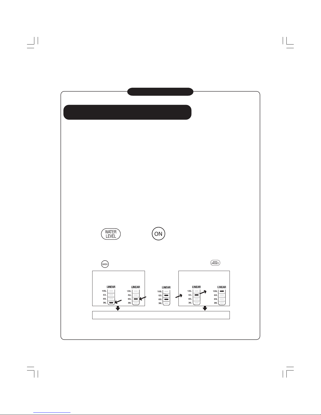
T h e wa te r leve l is auto matic a lly s et a c c o rdin g to the de te r gent a m ount. H o we ver, the wate r le vel may b e
a djus ted by the fo llowing metho d if the us er fe e ls tha t a u toma tic a lly s e t wa te r le ve l is too high or to o low.
When adjus ting a u tomatic ally s et water lev el
T h e wa te r leve l is auto matic a lly s et a c c o rdin g to the de te r gent a m ount. H o we ver, the wate r le vel may b e
a djus ted by the fo llowing metho d if the us er fe e ls tha t a u toma tic a lly s e t wa te r le ve l is too high or to o low.
Once a s etting is ma de, it will be s tored in the me mory.
While pres sing the
press the powe r . B uz z er bee ps . W a ter level indic a tor turns on.
(Auto power ON/OFF)
To lowe r the wa ter leve l
Press
to a dju s t
To raise the water level
Press
to a dju s t
Press twice. Press once.
(Decrease approx. 20L.) (Decrease approx. 10L.)
Press once. Press twice.
(Increase approx. 10L.)(Increase approx. 20L.)
Turn the P OWE R off. (F inis hed adjus ting)
– 15 –
– 16 –
One-Point Information
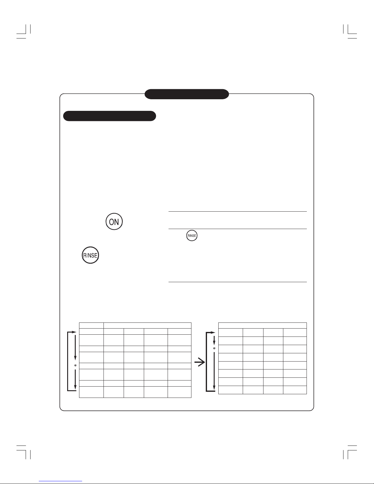
About Static Rinse Mode
1. “Static rinse” mode
There is a mode to change from “shower rinse” to “static rinse” mode by invisible button operation.
Use this mode for users who have a problem in “white rinsing water” or those who want longer rinsing.
(1) Applicable course
Concentrated standard, standard, soak and memory
(2) Mode setting method
1 of shower rinse becomes 1 of static rinse.
Rinse cycle becomes same as the case where bath water is used until rinse process.
1
Turn on the power.
2
Press button for 3 seconds. The setting completes
in approximately 5 seconds when the buzzer beeps.
Turn off the power.
• To return to shower rinse mode, perform the above
operation again. When the setting to shower rinse
completes, the buzzer beeps.
• Once the setting is made, it will be stored in the memory.
• The setting method for the past models, i.e., turn on the power while pressing “RINSE” + “COURSE”
can also be used.
(3) Rinse cycle
“Shower rinse” becomes “Static rinse” as shown in the table below.
Press the power
button, then
Press
for 3 seconds.
Display Rinse Cycle
1 rinse
Static
1 rinse + overflow
overflow rinse
Static
2 rinse + Shower overflow
overflow rinse
3 rinse Shower Shower
Static
3 rinse + Shower Shower overflow
overflow rinse
4 rinse Shower Shower
Static
4 rinse + Shower Shower overflow overflow
overflow rinse
Static Rinse Cycle
Static
overflow
Static
overflow
Static
overflow
Static
Static
overflow overflow
Static
Static
Static
Static
Static
Static
Static
Static
Static
Static
Static
2 rinse Shower
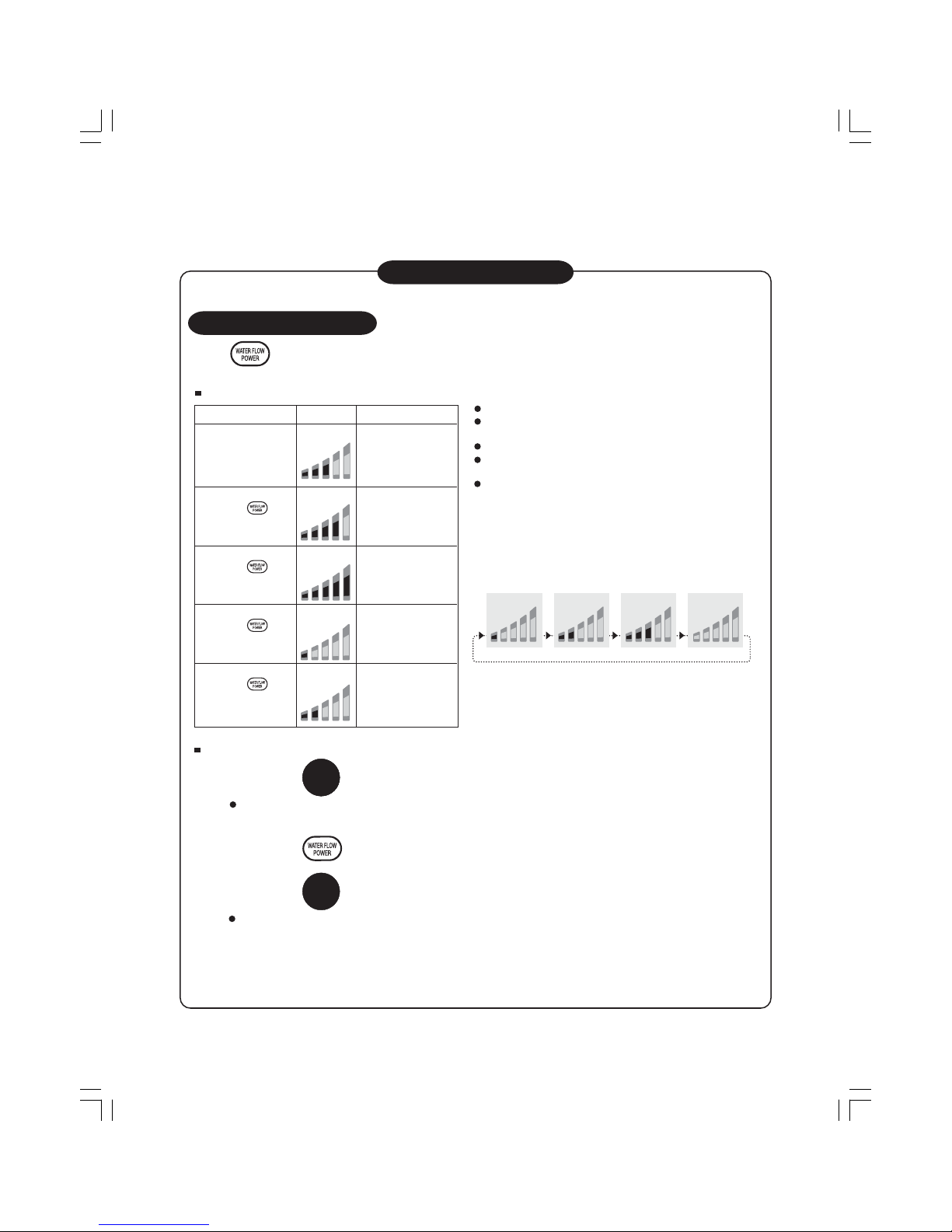
One-Point Information
Water Flow Power
How to choos e the water flow power
The water flow power during rins ing ca nnot be cha nged.
The water flow power can be adjus ted only any of
"REGULAR" and "MEMERY" is selected.
Clothes should not be washed by strong water flow power.
with the wate r flow po we r pre s et.
When the water le vel rea che s to a des igna ted leve l, the
water flow power will be indica ted. S uc h indic ation will be
repe a ted in the following order. T his me ans the operation is
being done under the water flow power pres et.
E xample (S tandard water flow power)
Ke y ope ra tion Dis play S ituation
Tur n on th e power. S ta nda rd wa te r flow
(Default)
Press the When you need to
button once. wa sh rather s trongly.
Press the When you need to
butto n twi c e. wa sh str on gl y.
Press the When you need to
butto n thre e tim e s . wa s h so ftly.
Press the When you need to
butto n fo ur times . was h ra ther s oftly.
HI
LO
HI
LO
HI
LO
HI
LO
HI
LO
HI
LO
HI
LO
HI
LO
HI
LO
Press button to cho os e the wa ter flow power a c c ordi ng to your ne eds su c h a s what to be
was hed or dirtines s level.
When you need to change the water flow power during operation
Press the button to hold the operation.
T he wa ter flow powe r will be gradually incre a s ed, a nd then be dec reas ed. Whe n you nee d to was h sensitive
clothes s oftly, hold the opera tion. Otherwis e, s uch c lothes may be da ma ged.
Press the butto n to choo s e the water flow power.
Press the
button again.
T he wa ter flow powe r will be cha nge d during the operation whe n you s elec t more tha n one leve ls of water.
1
2
3
When the "MEMORY" mode is set, the operation will start
– 17 –
– 18 –
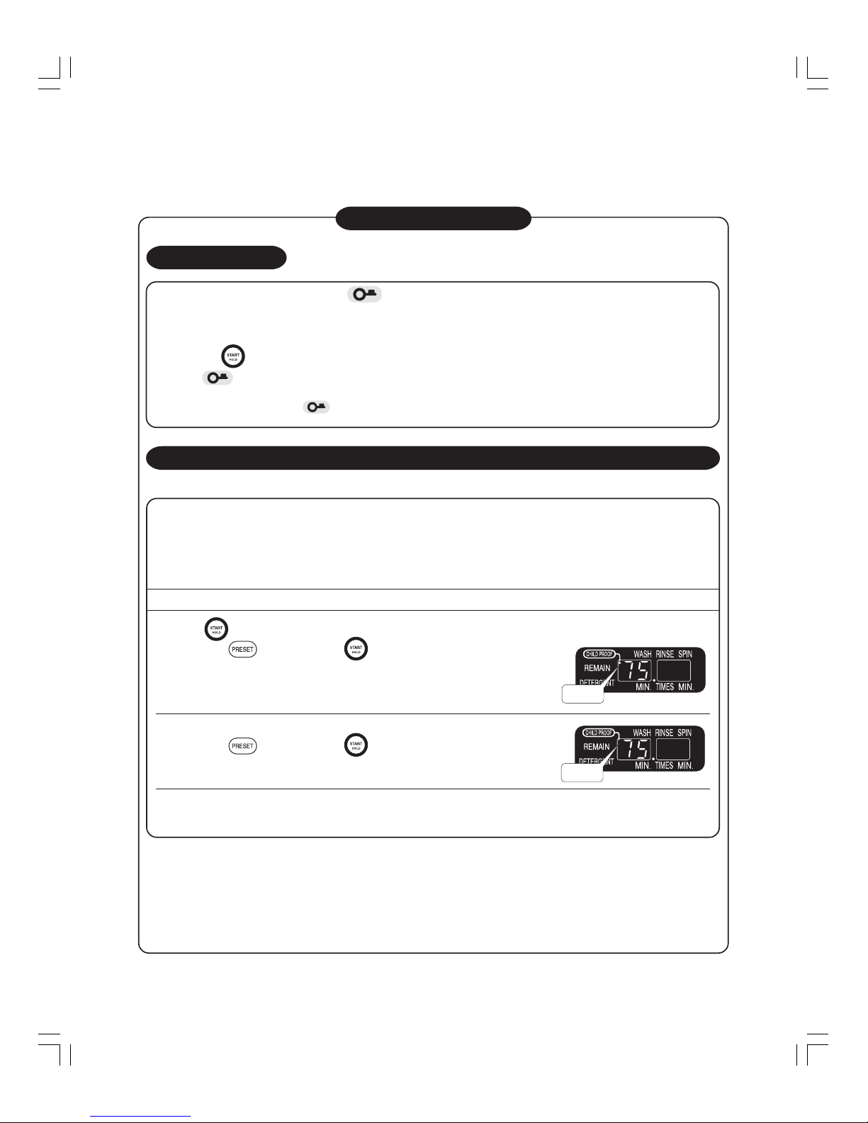
One-Point Information
CHILD PROOF mode
This model is equipped with CHILD PROOF mode. After this mode is set to ON, the lid can be locked so that children should
not fall into washing-spining tub during washing or drying. If you find the accident such as children’s falling into the wash tub,
please take necessary safety action urgently.
If there are small children who require attention, set this mode ON.
WARNING: Pay attention to small children. Do not leave the lid open. Do not leave the washer filled with water. Never allow
children to look into the basket or play around the washer. Do not place the stand or box etc. near the washer.
HOW TO USE CHILD PROOF MODE
Press the button, then the washing machine begins operating, follow the instruction below:
Hold down the
button, press the button once again.
•
A buzzer will sound and the CHILD PROOF mode indicator will be activated.
Once the CHILD PROOF mode is set, it is stored in memory.
Canceling the CHILD PROOF mode
Hold down the button, press the button once again.
•
A buzzer will sound and the CHILD PROOF mode indicator will be canceled.
Once the CHILD PROOF mode can be canceled even during the operation.
L Cannot add detergent while child proof mode. The lid lock is activated.
L If accident occur when strongly pull up lid when lid lock in child proof mode operate. The buzzer will be sound and operation
will stop. Subsequently if that state persists about 5 seconds, it will be detected as an alarm and water will be drained.
CHILD PROOF MODE (if you have small children)
LID LOCK
Instruction: Do not open the lid while lights up. (The lid may be damaged.)
At the end of washing, the lid will be automatically locked.
When you need to cancel the lid lock
L During operation
Press the button to hold the operation.
When
lights out, the lid can be open.
L While the power is off
Turn the power on. When lights out, the lid can be open.
(When the power is turned off or shut down during operation, the lid will be automatically locked.)
ON
OFF
– 1–
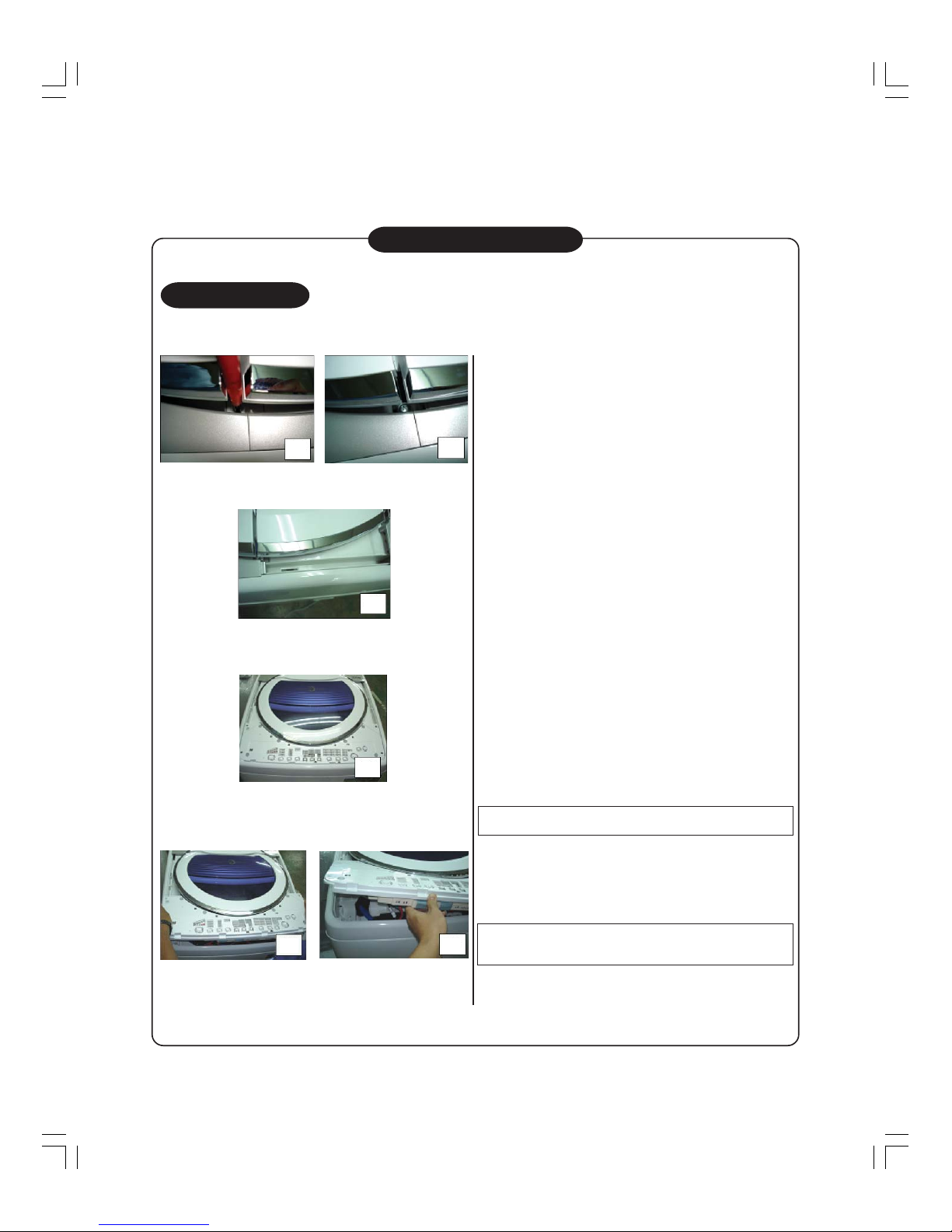
: If Lid Lock problem, wash lid assy cannot open.
One-Point Information
About Lid Lock
How to do?
1) Take off top cover cap of both side by lift up of
lid 1 & lid 2 at center position and use small minus
driver for open cap.
(Photo. 1 and Photo. 2)
2) Take off screw and then remove top cover deco
of both side(Right & Left side).
(Photo. 3)
3) Take off panel deco by pushing slide-up by hand.
(Photo. 4)
4) Take off 4 screws on control panel and then lift-up
(Photo. 5)
5) Move control panel assy to left side for lid lock
(Photo. 6)
move out from lid hook.
1
2
3
4
5
6
Note 1) Becareful lead wire unit.
Caution : Before take off must beUnplug for prevent
electric shock.
– –
2. Functions during each process
Process in which the lid is opened
1 During weight sensing
2 During water supply
3 During wash, rinse & agitation
4 During drain
5 During spin
6 During shower rinse
7 Before starting operation
(When the power is ON)
8 After course completes
(When the power is ON.)
9 When the power switch is OFF
Functions while the child proof is set
• No child proof function
•
No child proof function until the water reaches the reset level.
However, the child proof functions when the lid is opened
after the status of “lid closed” is detected during water supply.
Child proof functions.
• Basically, the child proof is to be set after star ting operation.
If the child proof is set and the lid is opened before starting,
the child proof functions as follows;-
1 When there is no water: No child proof function
2 When there is water: Child proof functions.
1 When there is no water: No child proof function even if the
lid is opened.
2 When there is water: Child proof functions when the lid is
opened.
(When the child proof is set, the power is not automatically
turned off after wash only or rinse only completes.)
Others • When the child proof is set, it functions when the lid is opened even when the start/stop
button is pressed to suspend the operation.
• If the operation is started while the lid is open, water is supplied just for a while and the
child proof functions once the water level reaches a certain level (reset level).
About Cancellation of Memory Data
This machine has data which will remain in the memory even if the power cord is unplugged or a power
failure occurs.
To initialize the memory data, turn on the power while pressing (Super Spin Dry). If this is carried out, the
buzzer sounds and all the settings are cancelled.
No. Memory Data Items Initialized Status
1 Buzzer for standard and other courses Sounds
2 Course button memory “Standard” turns on.
3 Description of memory course
“Standard” Wash: 8 min, Rinse: 2 times, Spin: 4 min
4 Water volume adjustment by the weight sensor Standard
5 Child proof setting No
One-Point Information
One-Point Information
– 2 –
One-Point Information
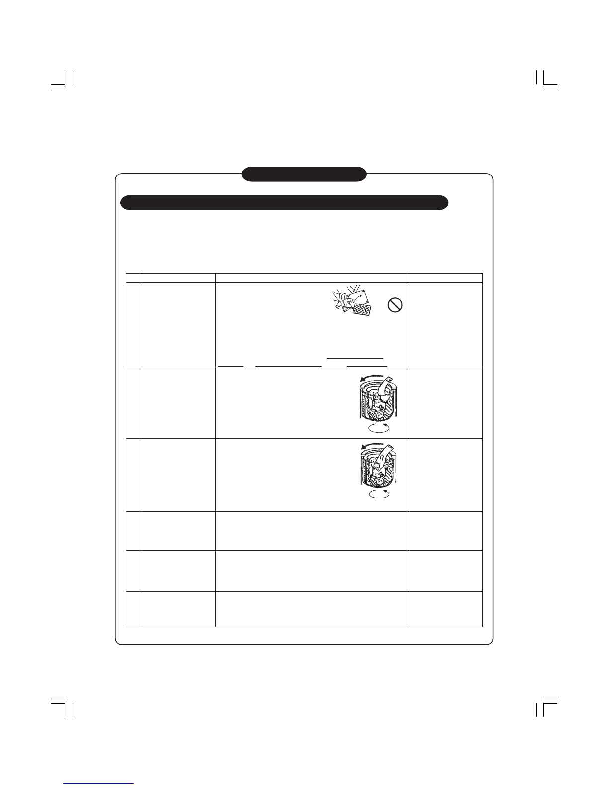
About Clothes for Which Care Should be Taken When Washing
Recently, more users think, in this environment where clothes types are diversified, that anything can be
washed with a fully automatic washing machine and actually wash various types of clothes in a washing
machine.
However, a fully automatic washing machine cannot wash every type of cloth that is said to be washable.
Please be reminded of the followings, which are also noted in the owner’s manual.
No.
1
2
3
4
5
6
Clothes
Waterproof type sheets,
mats and clothing
Ex. Cover for cars, sauna
suits, rain coat, ski wear,
sleeping bag, etc.
Clothing made of
synthetic fabric such as
polyester and nylon
Ex. Wind breaker, shirt,
etc.
Clothing made of thick
fabric
Clothes that is hard to
absorb water
Ex. Pillow, doll, cushion,
etc.
Clothing which carries a
laundry symbol denoting
hand wash or gentle
machine wash
Large item
Ex. Blanket, curtain, etc.
Symptoms
Injury hazard due to abnormal vibration
during spin process.
If waterproof clothes are spun, the water
in the clothes cannot be removed as this
type of cloth does not absorb water and thus
water starts rotating in the wash tub. If spinning by high-speed
rotation is performed in such a condition, the balance may be lost or
great vibration is applied to the tub itself because of sudden removal
of water. Abnormal vibration (impact) thus occurs on the washing
machine and this could result in not only
damage on washing
machine and tear and wear of clothing but also personal injury.
Clothing made of synthetic fabric may come
out of the tub due to centrifugal force during
spinning and this could damage the clothing.
<Symptom where the tub cover is damaged
may also occur.>
As clothing made of thick fabric becomes bulky,
it has a tendency to become difficult to be
agitated compared to other types of clothing.
Particularly when it is washed together with
other types of clothes, it becomes further
difficult to be agitated and could be damaged
by coming out of the tub during spin process
due to centrifugal force.
<Symptom where the tub cover is damaged may also occur.>
Items that still float even if pressed by hand cannot be washed.
Such items may come out of the tub during spin process and the
clothes, water tub cover or inner lid could be damaged.
In the case where this type of clothing is washed in heavy water flow,
i.e., standard course, it may shrink or be damaged even if it is put
inside the laundry net.
Blanket
Unless otherwise stated, this type of item may come out the tub and
be damaged if a blanket net is not used.
<Symptom where the tub cover is damaged may also occur.>
Notes on clothes
No washing of waterproof
type sheets, mats and
clothing.
Warning stated on the
owner’s manual.
(Hand wash or seeking
laundry service by a
specialist is recommended.)
If there is a large amount
to be washed, reduce the
amount.
Push a small amount
inside the tub to wash.
Do not wash together with
other types of clothes.
(It is recommended to
wash thick clothes alone
without mixing other
types.)
Do not wash items that
still float if pressed by
hand.(Hand wash is
recommended.)
Select a course with
gentle water flow (such
as gentle course)
following the laundry
symbol or instruction.
Wash a large item using
the blanket course.
Use a blanket net unless
otherwise stated.
No washing
– 2 –
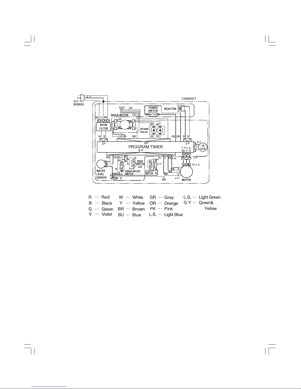
5. SCHEMATIC DIAGRAM
– 2 –
About operation check during installation
Notes on Installation
1. Wash operation check
• Plug in the power cord and press the “POWER” button. Then, press the “START” button.
• Pulsator rotates clockwise and counterclockwise direction. Detergent amount 0.2 cup is displayed.
∗ Knocking sound is heard when plugging in. However, it is not abnormal.
2. Spin operation check
• Close the lid and press the “POWER”, “SPIN” and “START” buttons in this sequence.
∗ Before spinning starts, the wash tub rotates slowly and a clicking operation sound is heard because
the clutch is switched from washing to spinning.
∗ The brake works at the completion of spinning. Then the wash tub rotates and the clutch switching
from spinning to washing is performed.
∗ For the course operation, the clutch switching from washing to spinning and vise versa will be
performed automatically.
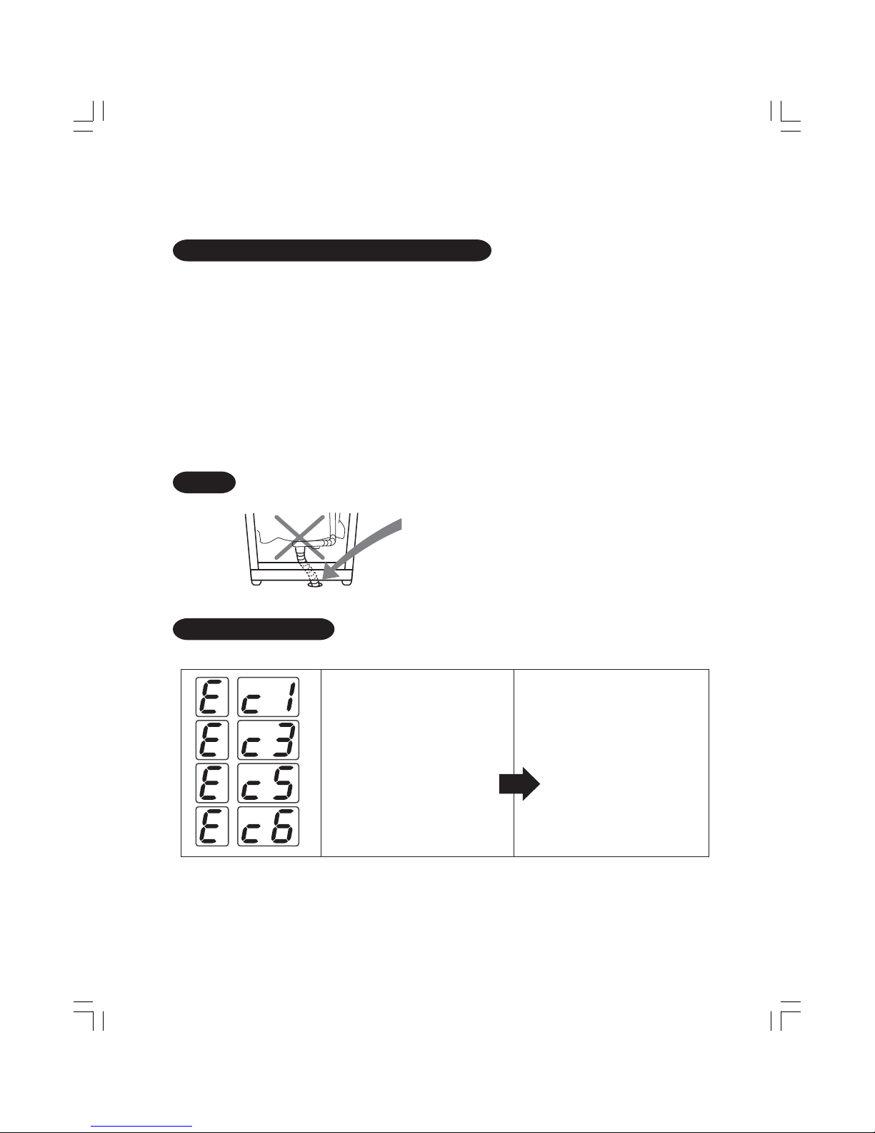
NOTE Never do as shown in the drawing below.
Direct insertion of the drain hose from
interior of the washing machine into the
drain hole could result in water leakage
or abnormal noise.
About Error Display
When the following errors are displayed, carry out the inspection stated below.
• Is too much laundry put into the
tub?
• Is the water level set to too low for
the laundry load?
∗ If the error is not solved even after the above inspection, please request repair service.
• Turn off and on the power. Reduce
the laundry or reset the water level
and then press the start button
again.
6. CHECKING PROCEDURES

– 2 –
Abnormality Alarm
(1) Error display and description of abnormality alarm
• In case of abnormality or failure such as incorrect operation and faulty drainage or spinning, the operation is
stopped by error display and abnormality report (buzzer alarm).
Error Display
Abnormal
drainage
Abnormal
open lid
Abnormal
unbalance
E31, E32
Abnormal
water supply
Abnormal
motor current
E61, E63~66
Description of Detected Error
• After starting draining in wash or spin process, the water level does not
go down below the reset level even after the specified time has elapsed.
(To be detected by the water level sensor) [7 mins 30 secs]
• Occurred by drain hose that was not put down or flattened hose, etc.
• The lid is open or opened during spin in rinse and spin process or during
shower rinse operation. (To be detected by the lid switch)
(E21):The lid is opened, while spining or switching of clutch.
• Unbalance occurred by uneven laundry load during the final spinning.
(Unbalance detected t rectifying operation was repeated but the
unbalance was not rectified.)
(Abnormality alarm) When an unbalance was detected 3 times during the
same spin process. In dry course, however, abnormality alarm sounds at
the first abnormality detection.
(E31): When abnormality was detected by the lid switch unbalance. (To be
detected by the lid switch)
(E32): When abnormality alarm was detected by the vibration sensor. (To
be detected by the rotation sensor.)
• When the water level reaches the following water level during water supply
in wash and rinse process or while rectifying an unbalance, the water does
not rise up to the water level of one-level higher even after a specified time
has elapsed. (To be detected by the water sensor)
• Occurred by a tap which was not turned on or water supply valve failure,
etc.
• Overcurrent flows through the motor while the motor is running (for all
processes).
(Current value flowing through the motor drive circuit is detected by the
program timer assy.)
• Occurred by excessive laundry load, too low water level, defective wiring
between the motor and the program timer assy, motor drive circuit failure,
etc.
(E61): While washing (E63): Abnormality occurred while spinning and there
was no problem during washing.
(E64): Occurred when spin only is set. (E65): When clutch is switched to
washing.
(E66): When clutch is switched to spinning.
How to Cancel
After opening and closing
the lid, press the start
button. The operation
resumes from the stopped
state.
Open and close the lid.
The operation resumes
from the stopped state.
Tu r n o ff and on the power
(OFF/ON) button.
Operation will not
continue. Start back the
operation from the
beginning again.
Detected water level Detected time
97 ~ 105L 16 minutes
91 ~ 97L 12 minutes
82 ~ 91L 18 minutes
76 ~ 82L 12 minutes
69 ~ 76L 14 minutes
60 ~ 69L 18 minutes
55 ~ 60L 10 minutes
46 ~ 55L 18 minutes
36 ~ 46L 20 minutes
0 ~ 36L 52 minutes
E21, E23
After opening and closing
the lid, press the start
button. The operation
resumes from the stopped
state.
(E23):The lid lock is not locked or is not released.
(E21):Close the lid. The
operation resumes from
WKHstopped state.
(7XUQoff and on the
SRZHU2))ON)button.
Operation will not continue.
Start back the operation
from the begining again.

– 2 –
Error Display
Abnormal
motor current
E71, E73~74
Abnormal
motor voltage
E81, E83~86
Abnormal
water leakage
Abnormal
DC voltage
Abnormality
in the clutch
EC1, EC3
EC5, EC6
Leakage
current
detected
Abnormal water
(During air
drying)
During air
drying
Abnormal
overload alarm
Description of Detected Error
• Abnormality occurred in the sensor signal which detects motor rotation while the
motor is running (for all processes).
• Occurred by excessive laundry load, too low water level, defective wiring
between motor and program timer assy, motor drive circuit failure, etc.
(E71): While washing (E73): Abnormality occurred while spinning and
there was no problem during washing.
(E74): Occurred when spin only is set. (E75): When clutch is switched to
washing.
(E76): When clutch is switched to spinning.
• Excessive voltage was added to the program timer assy by the motor while the
motor is running (for all processes).
(Voltage value applied to the motor drive circuit is detected by the program
timer assy.)
•
Occurred by excessive laundry load or motor program timer assy failure, etc.
(E81): While washing (E83): Abnormality occurred while spinning and there
was no problem during washing.
(E84): Occurred when spin only is set. (E85): When clutch is switched to
washing.
(E86): When clutch is switched to spinning.
• The water level of the water tub became lower than the reset level during
agitation ( in wash and rinse process). (To be detected by the water level
sensor)
• Occurred by crack on the tub, foreign matters stuck in the drain valve, water
level sensor failure, etc.
•
DC voltage of the motor drive power circuit is too low while the motor is stopped.
(Voltage value applied to the motor drive circuit is detected by the program
timer assy.)
• Occurred by defective wiring in the machine or motor program timer assy
failure, etc.
• Clutch switching was not performed correctly (wash t spin, spin t wash) for
all processes. (To be detected by the clutch sensor)
• Occurred by excessive laundry load, clutch failure or clutch sensor circuit
failure, etc.
(Ec1) When the clutch is released during washing (Ec3) When the clutch
is applied during spinning (Ec5) When the clutch was not switched to washing.
(EC6) When clutch was not switched to spinning.
• Leakage current occurred on the main unit of the washing machine. (To be
detected by the leakage current detection sensor inside the program timer assy
after turning on the power and before pressing the start switch)
(Detectable leakage current is 1mA or below.)
• Occurred by submerged electrical components on the bottom part, freezing or
water splashing, etc.
• Water level sensor output is above the reset level when drying starts.
(To be detected by the water level sensor)
• Occurred by drying operation started while there is water in the tub.
• Occurred by excessive laundry load, etc.
• Occurred by tangled laundry.
How to Cancel
Tu r n o ff and on the
power (OFF/ON)
button.
Operation will not
continue. Start back
the operation from the
beginning again.
Unplug the po
wer
cord.
Tu r n o ff and on the
power (ON/OFF)
button, operate spin
only and drain water.
Turn on the power
again and perform
drying operation.
Reduce laundry
amount or fluff the
laundry, then press
the start button.
Abnormal
water level
sensor
Water level sensor output is out of normal area.
Occured by detective connector of water level sensor, detective
connector of air tube.
Occured by program timer assy failure, water level sensor failure,etc.
•
•
•
Turn off and on the
power(OFF/ON)
button. Operation will
not continue. Start
back the operation
from the begining
again.

– 2 –
Detailed Description of E6, E7, E8 and Ec Errors
On the above error table, error description is classified and stated.
The table below shows how to identify, with the last number of the error display, the process where the error
had occurred.
Check the laundry overload when E6, E7, E8 or Ec occurred.
Overload: Laundry more than the rated load is put in the washing machine,
The water level is set to extremely too low for laundry load, etc.
Error Display
E6 E7 E8 Ec
1 In wash process In wash & rinse process
2 NIL NIL
3 There is no problem in wash process but In spin process
abnormality occurred in a subsequent
process
4 When spin only or rinse only is set When spin only or rinse only is set
5 At the clutch switching from spin to wash At the clutch switching from spin to wash
6 At the clutch switching from spin to wash At the clutch switching from spin to wash
Last number
(2) Actions to be taken against error alarm, etc.
Error Display
Abnormal
drainage
Abnormal
open lid
Abnormal
unbalance
E31, E32
Abnormal
water supply
Check Items & Description t Actions to be Taken in Case of Abnormality
• Check around the drain hose (Forgot to put down the hose, flattened hose,
hose tip submerged in the water, a sleeve installed, extension of hose, etc.)
<Most of the water in the wash tub has been drained>
• Check the water level sensor and air tube.
<Most of the water in the wash tub has not been drained>
• Check the drain valve operation.
• The lid is open t Close the lid.
• Error is displayed even if the lid is closed.
t (1) Check the safety lever distance.
(2) Check the operation of the lid switch.
• Is the laundry load uneven? t Make it even.
• Is the washing machine installed on an uneven or inclined floor surface?
t Rectify the unevenness to secure levelness. (Check with a level.)
• Check the installation of the drain hose. (Perform the same check as E1)
• Check the lifting rod. t Replace the rod.
• Check the operation of the cover switch. (Perform the same check as E2)
• Is the tap not turned on? (When a bath water pump is used, this error may
be displayed during rinsing.) t Turn on the tap.
• Is dust or rubbish accumulated on the net of the water supply port?
t Clean the net of the water supply valve.
• Check the operation of the water supply valve.
Relevant Places
• Around the drain hose
• Water level sensor
• Air tube
• Drain valve
• Junction lead wire
• Program timer assy
• Lid
• Lid switch
• Junction lead wire
• Program timer assy
• Uneven laundry load
• Installed place
(Unevenness,
inclination)
• Around the drain hose
• Lifting rod
• Around lid switch
• Forgot to turn on the tap.
• Dust or rubbish on the
net of the water supply
valve
• Water supply valve
• Junction lead wire
• Program timer assy
Safety lever distance
59±4mm
E21, E23
(3) Check the operation of the lid lock.
Lid lock
Around safety lever
•
•

– 2 –
Error Display
Abnormal
motor current
E61, E63~66
Abnormal
motor rotation
E71, E73~76
Abnormal
motor voltage
E81, E83~86
Abnormal
water leakage
Abnormal
DC voltage
Abnormality
in the clutch
Ec1, Ec3
Ec5, Ec6
Leakage
current detected
Abnormal water
(During air
drying)
During air drying
Abnormal
overload alarm
Check Items & Description t Actions to be Taken in Case of Abnormality
• Laundry load exceeds the rated load. t Reduce the laundry amount.
• Water level is extremely too low than laundry load.
t
Make the set water level higher.
∗ It can be thought that the load on the pulsator became too large and the pulsator due
to excessive laundry load thus became locked. This could be a cause of an overcurrent
flowing in the motor.
• Check the operation of the motor.
∗ The followings are thought to be other factors (including occasional factors) of this error.
(1) Current is not correctly switched to the motor due to defective wiring, etc.
(2) The motor become locked due to the stuck or suspended clutch.
(3) Current is not correctly switched to the motor due to influence of external noise, etc
• Perform the same check as E6.
∗ It can be thought that the load on the pulsator became too large due to excessive laundry
load and the pulsator thus became locked. This could be a cause of interruption of the
motor signal.
∗ The followings are thought to be other factors (including occasional factors) of this error.
(1) Defective wiring between the motor and the program timer assy
(2) The motor become locked due to the stuck or suspended clutch.
• Perform the same check as E6.
∗ It can be thought that the load on the pulsator became too large due to excessive laundry
load and the pulsator thus became locked. This could be a cause of counter electromotive
current generated from the motor.
∗ The followings are thought to be other factors (including occasional factors) of this error.
(1) Program timer assy failure (detection circuit or microcomputer surrounding circuit failure)
(2)
Defective wiring inside the machine (disconnection or poor contact at the connector)
NOTE: The state where the circuit voltage becomes highest is when the lid is
opened during spin top rotation. To perform reproduction for checking, carry it out at
the abovementioned operation status.
• Fill the water inside the water tub and check water leakage from the tub or drain valve.
t Repair the water leaking part or replace the component.
• Check the operation of the water level sensor.
• Check AC supply voltage. (Reduced up to approx. AC35V or exceeds AC160V)
t Check the power supply wiring.
∗ The followings are thought to be other factors (including occasional factors) of this error.
(1) Defective wiring inside the machine (disconnection or poor contact at the connector)
(2) Program timer assy failure (detection circuit or microcomputer surrounding circuit failure)
• Perform the same check as E6.
∗ It can be thought that the load on the pulsator became too large due to excessive laundry
load and the pulsator thus became locked. This could be a cause of the clutch that cannot
be switched.
∗ The followings are thought to be other factors (including occasional factors) of this error.
(1) Defective operation of the clutch mechanism
(2) Clutch sensor failure (including defective wiring)
• Is the bottom part of the washing machine submerged in the water due to clogging of the
waterproof pan, etc.?
t Clean the clogging.
• Check if dew condensation occurred on the motor, etc. in cold morning.
t Dry up well. (Insulation resistance 3MΩ and above)
• Leakage current from other electrical components than motor could occur.
t Check the insulation resistance of each electrical component.
• Is water left in the machine?
t Drain the water.
• “A” may be displayed even when there is the same symptom as “E1”.
t Take the same actions as in case of “E1”.
• Is too much laundry put in the machine?
t Reduce the laundry.
• Is the laundry tangled?
t Fluff the laundry and put it again.
Relevant Places
•
Excessive laundry load
• Too low water level
• Junction lead wire
• Clutch
• Clutch sensor
• Program timer assy
•
Excessive laundry load
• Too low water level
• Junction lead wire
• Clutch
• Program timer assy
•
Excessive laundry load
• Junction lead wire
• Program timer assy
• Water tub
• Drain valve
• Water level sensor
• Junction lead wire
• Program timer assy
• Power supply wiring
• Junction lead wire
• Program timer assy
•
Excessive laundry load
• Too low water level
• Clutch mechanism
• Clutch sensor
• Junction lead wire
• Program timer assy
• Submerge
• Dew condensation
• Water splashing
• Program timer assy
• Water left in the
machine
• Same places as in
“E1”, such as water
level sensor and drain
valve
• Excessive laundry to
be dried
Abnormal
water level
sensor
Check connector of water level sensor, connector of program timer assy.
Check connection of air tube.
Program timer assy failure, water level sensor failure,etc.
•
•
•
Water level sensor
Air tube
Junction lead wire
Program timer assy
•
•
•
•

Detailed Failure Diagnos is Method
(1) Setting method of inspection mode and description of inspection
In the inspection mode, failure diagnosis of each electrical part can easily be checked on the control panel. If an
abnorma l a la rm s ounds a nd there is a problem in the was hing ma c hine, ide ntify the faulty e lectric al part by this
inspection mode and ca rry out the failure diagnos is of eac h elec trical part (Page 29).
If the connector is disconnected and reconnected, carry out the checks under this inspection mode again after
the r e pa ir c om pl e te s and ma ke su re tha t th e motor s tar ts rota tion w he n s tar tin g s pinn in g a nd tha t no a bno r ma l
ala rm s ounds when the s pinning operation is performed for 1 minute.
Wa ter level indica tor
Process indicator
Course indicator
1. While pres sing down the
butto n, pre s s the button. (The buzzer beeps.)
2. Press the
button. ( T he was hing ma chine will be in s tandby mode. ) (P res et time: 10 minutes )
3. A fter the ins pe c tio n c o mple tes , ca rry o ut a uto ma tic power o ff with the
butto n.
The power is then turned off.
No.
1
2
3
4
5
6
7
8
9
Chec k Items
Motor forward
ro tati on
Motor forward
ro ta tion ( H igh
speed)
R o tati on
sensor
function
Function of
water supply
valve (on the
ta p s ide)
Function of
water supply
valve (on the
softener side)
Drain valve
function
Clutch sensor
input
Water level
input
Lid switch
input
Operation under Normal C ondition
By pressing the
butto n, the m oto r rota tes
forwards after the clutch is switched to washing.
T he motor ro ta te s forwa rds ( a t hig h s peed ) a fte r
the clutch is switched to washing by pressing the
butto n wh il e p re ss ing th e button .
Ac cor di ng to the motor s pee d, outpu t of 2 r ota tion
sensors is displayed on the digital LE D.
P ink lea d sens or: Wa s h LE D
Yellow gree n lea d sens or: S pin LE D
The water supply valve (on the tap side) works for
15 seconds by pressing the
butto n.
The water supply valve (on the tap side) works for
15 seconds by pressing the
butto n.
Drain valve motor works for 15 seconds and then
clutch is switched to s pinning by pres sing the
butto n.
According to the clutch status, the process
ind ic a tor tur ns on/o ff.
Spin side: OFF, Wash side: ON
Wa ter level in the wa ter tub is dire ctly dis played
on the wa ter leve l indic ator.
C ours e i ndi c a tor tur ns on/of f a ccordin g to ope n/
clos e of the lid.
Lid open: O F F, lid clos ed: O N
Chec k Items in C as e of Abnormality
(Normal Value)
R esistance between CN4 blue - CN6 red (10 ~ 20 )
R esistance between CN4 blue - CN5 purple (10 ~ 20 )
R esistance between CN6 red - CN5 purple (10 ~ 20 )
* Measured value when unplugged and CN4-6 is removed.
R esistance between CN4 blue - CN6 red (10 ~ 20 )
R esistance between CN4 blue - CN5 purple (10 ~ 20 )
R esistance between CN6 red - CN5 purple (10 ~ 20 )
* Measured value when unplugged and CN4-6 is removed.
CN7
Voltage between black - yellow (5V)
Voltage between black - pink (5V 0V
...
)
Voltage between black - yellow green (5V 0V
...
)
Voltage between CN1 black - CN9 pink
(S tandby state: AC 220-240V
, during operation:
0V)
Voltage between CN1 black - CN9 light
blue
(S tandby state: AC 220-240V, during operation:
0V)
Voltage between CN1 black - CN9 brown
(S tandby state: AC 220-240V) (During
operation:
0V
Voltage betwee n C N9 re d-ora nge
(S tandby state : AC 0V
during latch opera tion : a bout DC300~330V)
Voltage between CN7 black - red
(Lid open, clutch on spin side: DC5V )
(Lid closed, clutch on spin side: DC 3.3 ~ 4.2V)
(Lid open, clutch on wash side: 0V)
(Lid closed, clutch on wash side: 0V)
Ac cording to (4) Wa ter level s ensor failure
diagnosis method
Voltage between CN7 black - blue
(Lid open, clutch on spin side: DC5V )
(Lid open, clutch on wash side: DC2.7 ~ 3.3V)
(Lid closed, clutch on spin side: 0V)
(Lid closed, clutch on wash side: 0V)
Failur e
Diagnosis
of Electrical
Parts
1
2
3
4
5
6
Inspection
mode s etting
(P rocedures )
Motor
Water
s upply
valve
Drain
valve
motor
Clutch
sensor
(cup assy)
Water
leve l
sensor
Lid
switch
operation time : about 1 second
Lid
Lock
10
Lid lock
input
Lid lock locks by pres sing the ( W ater leve l) bu tton.
Lid lock releases by pressing the (Water flow
power) button.
(L id lock)L ED turns on by locked c ondition.
(L id lock)L ED turns off by re leas ed condition.
Voltage between CN10 black-white
stanby state(release or lock position) : about
0V, during operation (release lock, lock
relea s e) AC 220-240V
7
– 2 –

– 2 –
(2) Failure Diagnosis of Each Electrical Part
No.
1
2
Part
Program
timer motor
Clutch
sensor
(Cup assy)
• Water
supply
valve
• Lid Lock
Failure Diagnosis Method
• Inspection mode 123 (Make sure that there is no problem in common check items stated on Page 2.)
The motor does not rotate.
Does the rotation indicator
change when the pulsator is
turned manually after setting to
the inspection mode?
Changes
No change
Is the voltage between CN7
black – yellow DC5V?
Ye s
No
Short or open
Unplug the power cord,
remove the CN4 ~ 6 of the
program timer and measure
the resistance between
(red) – (purple), (red) – (blue)
and (blue) – (purple) on the
main unit lead wire side.
When rotated, does the voltage
between CN7 black – yellow
green and between CN7 black –
pink change from DC5V to 0V?
All approximately
10 ~ 20Ω
Program timer failure
No change
Changes
Motor failure, disconnected lead wire
unit connector or wire disconnection
Ec5 error is displayed but the
clutch is on the wash side.
Is CN7 black – red shorted when
unplugged and CN7 is removed?
Open
Disconnected lead wire unit
connector, wire disconnection or
cup assy failure
Short
Program timer failure
• Inspection mode
4~5
,
Is the voltage at the checked point AC220V
in standby status?
No
Failure of each electrical part,
disconnected lead wire unit
connector, or wire
disconnection
Ye s
Does the voltage at the checked point change
from AC220V to 0V when operated?
Changes
No change
Program timer failure
Each electrical part failure

– –
No.
3
4
Part
1 Drain
valve motor
2 Drain
valve
Latch signal
Clutch
sensor
(Cup assy)
Clutch
sensor
(Mechanical
part)
Failure Diagnosis Method
• Inspection mode
Check the voltage between CN1 (black) –
CN9 (brown) in the standby status. Is it
AC220V?
No
Drain valve motor failure,
disconnected lead wire unit
connector or disconnected wire
Ye s
Check the above voltage when winding completes.
Does it change from AC220V to 0V?
(Check the voltage during winding.)
Changes
No Changes
Drain valve motor failure
Program timer failure
Check the voltage between CN9 red – gray
in the standby status. Is it about DC 0V?
No
Drain valve motor failure,
disconnected lead wire unit
connector or disconnected wire
Changes
No Changes
Program timer failure
Lid Lock failure
The clutch is on the spin side but
the clutch sensor does not judge
that it is on the spin side.
Is between CN7 black – red
open when plugged and CN7
is removed?
Short
Lead wire unit connector short or
cup assy failure
Open
Program timer failure
• Check in the inspection mode 1236
L atch of Drain valve does not work.
Check the voltage between CN9 red-RraQJH
during latch operation. Is it about DC0aV?
during latch operation :
press [Power ON] ,and press [start]
during about 1 second.
6
3

– 3 –
No.
5
6
Part
Water level
sensor
Lid switch
Failure Diagnosis Method
• Inspection mode 8
Are all the water level indicators
turned off when there is no water
in the water tub?
All turned off
What is the indicated water level
when water is supplied into the
water tub? (Refer to the table
below)
Lower level is
indicated.
Water level for each water level indicator
Any of them is
turned on.
Higher level is
indicated.
Is the 3P connector of
the water level sensor
disconnected?
Disconnected
Connect
Not disconnected
Water level sensor
failure or program
timer failure
Higher level
is indicated.
Check disconnection of or tear on the air
tube, foreign matter stuck inside or water
gone inside the air trap, etc.
Auto
Display Water volume Water level height
1
2 82L Approx. 280mm
3 60L Approx. 200mm
4 36L
Appr
ox. 100mm
• Inspection mode
Check the voltage between CN7 black – yellow.
Is it DC5V?
Ye s
No
Program timer failure
Does the voltage between CN7 black – blue
change from DC3V to 2.5V when the lid is
opened and closed while the clutch is on the
wash side?
Changes
No changes
Connector of the lid switch or lead
wire unit is disconnected or the lid
switch or lead wire unit is
disconnected.
7
Lid Lock
sensor
• Inspection mode
Lid Lock sensor can not detect
Iock or release condition.
Check connection of lead wire unit
connector of Lid Lock.
Does the voltage between CN10
white-black change?
Lid Lock : standby state about 0V
release position
lock position
release lock
Lid Lock : during operation AC0V
rlock release
10
Program timer failure
Lid lock failure
AW-SD1567\SH
No changes
Changes
10L Approx. 410mm
9

– 3 –
Common check items when a DD
motor-related error occurred
(Applicable error display: E6, E7, E8 & Ec)
E6, E7, E8 & Ec errors are the errors occurred by excessive washing load, too low water level for the washing load,
rotation sensor failure, clutch sensor failure, defective operation or failure of clutch mechanism, drain valve motor
failure, electronic unit failure, incomplete contact of in-machine wiring and wire disconnection.
Depending on the detecting situation, error display may not always be the same even when a deficiency occurred on
the same place. Please check the operation of the motor and clutch following the procedures shown below.
Are clothes more than the rated load put in the machine?
Within the rating
Is water level set lower for the washing load?
Appropriate water level
Turn off the power and take clothes out of the machine.
More
Lower
Reduce the clothes up to the rating.
Raise the water level.
Check the clutch sensor position according to the detailed failure diagnosis method. (Page 2)
Wash side Spin side
Check if the spin tub is rotated manually and locked.
Manually rotate the spin tub in clockwise and
counterclockwise direction.
(Switch the clutch to the wash side manually.)
Locked (wash side)
Check <A>
Rotate the pulsator by hand
to check the input of the
rotation sensor signal.
Free (spin side)
Clutch sensor failure
Electronic unit failure
Was the clutch input switched to the wash side?
It still remains at the spin side.
The input changes synchro-
nizing with the rotation.
Check the forward rotation
(according to the failure
diagnosis method)
It rotates smoothly.
Turn off the power and
check the spinning
operation.
Normal
(To the next page)
Does not change
synchronizing with rotation.
Rotation sensor failure
Incomplete contact of
wiring, disconnected wire,
electronic unit failure
It does not rotate smoothly,
or
It does not rotate.
Incomplete contact of
wiring, disconnected wire,
Electronic unit failure
Motor failure
Spinning operation cannot
be performed.
Electronic unit failure
Clutch mechanism failure
The spin tub is
locked and the input
was also switched
to the wash side.
To Check <A>
The spin tub is locked
but the input is still at
the spin side
Clutch sensor failure,
disconnected wiring,
incomplete contact,
electronic unit failure
The clutch is still at the
spin side.
Clutch mechanism
failure
Drain valve motor failure

– 3 –
Actions to be taken when the motor and
clutch switching were judged to be normal
If the motor and clutch switching were judged to be normal, check whether or not there is no abnormality on
wiring connection (incomplete connection of connector or incomplete contact etc.) again.
When an abnormality cannot be identified due to the reason of occasional abnormal occurrence, etc., check
the number of abnormality occurrence and observe the situation for a certain period of time.
(It is suspected that the abnormality is due to certain usage condition including excessive washing load or
condition of clothes.)
∗ How to check the number of abnormality occurrence: Refer to Page 3
Simple checking method in case of abnormal motor operation
Failure of drive circuit inside the electronic unit, abnormal motor coil, disconnected wiring and incomplete
contact, etc. are suspected to be a cause of abnormal motor operation. Carry out the check by the following
methods.
The motor does not rotate or the rotation is not smooth.
Remove 3 of 1P connectors CN4 – 6 (red, blue, purple) of the electronic unit.
Check the resistance value among 3 removed connectors. (Resistance value: 10 ~ 20Ω)
Abnormal
Electronic unit failure
Resistance value: Larger
Resistance value: Smaller
Remove the rear lid and remove 3 of 1P
connectors (red, blue, purple).
Then check the resistance value among
3 terminals on the motor terminal.
Remove the rear lid and remove 3 of 1P
connectors (red, blue, purple). Then
check the resistance value among 3
terminals on the motor terminal.
(ex: Between red and blue)
10 ~ 20Ω
20Ω and above No continuity
There is continuity
Disconnected wiring or
incomplete contact
Motor failure
Defective wiring insulation
Normal

– 3 –
White : AC 220-240V
AC 220-240V
White and Black : AC 220-240V
Orange : Drain valve
Gray : AC 220-240V
Brown : AC 220-240V
Blue : AC 220-240V

Displaying Method of the Number of Error
Occurrence and Its Clearing Method
(1) Displaying method of the number of error occurrence and its clearing method
The number of past error occurrence is kept in the memory and can be displayed on the control panel.
Memoriz ed number of error occurrence can a ls o be cleared. U s e this function to check the failure for any
repa ir work or to che ck the c onditions a fter repair.
Digital LED display
T I M E R button
WAS H butto n
R IN S E button
C OU R S E button
S TAR T butto n
Dis pla y S ample on B utton Des cription
Number LE D Display
[S etting of dis play mode]
W ith in 3 min ute s a fter tur ning on the powe r button, pre s s th e WA S H
and R INSE button for approximately 1 second.
E rror number is displayed on the number LE D.
(The buzzer beeps.)
(T he power is au toma tically turn e d o ff in 1 0 min ute s. )
(S ubse que ntly, operations will be in dis play mode.)
[C hange error numbe r (increment)]
E rror number increments. Every time TIMER button is pressed, the
display cha nge s as follows: E 1 E 2 E 3 E 5 E 6 E 7 E 8 E 9
EP Ec EL EA AF
[Change error number (decrement)]
E rror number decrements. E very time WASH button is pressed, the
display cha nge s as follows :
EP E9 E8 E7 E6 E5 E3 E2
[Dis play the number of error occurrenc e]
After selecting the error number by the above method using TIME R or
WAS H button, press S TART button. The number of past occurrence of
that error will be displaye d.
(Displayed in 3-digit number. Max. displayed number: 255 times)
(Display "000" means the number of error occurrence is 0.)
[C lea r the me morized number of errors ]
Memoriz ed number of errors can be cleare d.
(The buzzer beeps.)
(Memor ize d numbe r of a ll the e rrors will be cle ared. )
Use it when necess ary after repair.
(To c heck the completed re pa ir works on a later day, etc. )
WAS H
and
RINSE
TIME R
WAS H
START
START
and
COURSE
(T his ca n be us ed for any
displayed error number.)
(E x: E 2 error occ urred
9 ti me s in the pa s t.)
E1 E95 E23 E- FA EA EL Ec
E- E23 E95
– 3 –

– 3 –
Symptoms That Are Easily Suspected As a
Failure
Symptom Check Points Actions to be Taken
(1) Error is displayed
on the timer display
and electronic
buzzer sounds.
(2) Operation stops
in the midst of a
process.
(3) “WASH, RINSE
and SPIN” buttons
do not work when
a process is under
way.
(4) “START/STOP”
button does not
work.
(5) Water cannot be
drained effectively.
Water cannot be
drained.
It is difficult to
drain the water.
(E1 is displayed.)
Check following “Abnormality Alarm” on Page 2 ~ 2.
1 Is “Abnormality Alarm” mentioned on the above (1)
made?
2 Has the process where spinning is omitted been set?
If the process where spinning is omitted is set, the
operation stops at the completion of the final rinse
without performing draining.
1 Is the “START/STOP” button pressed after laundry
started?
2 Is a change made in the midst of rinse or spin
process?
(Rinse and spin process cannot be changed in the midst
of the process.)
Has the timer been set?
1 Has the process where spinning is omitted been set?
2 Is the drain hose raised
due to a doorsill, etc.?
(Is the abnormality alarm
“E1” made?)
3 Is the drain hose raised
due to a doorsill, etc.?
(Is the abnormality alarm
“E1” made?)
4 Is a commercially available
thinner hose (25
φ) used
as an extension of the
drain hose?
(Is the abnormality alarm
“E1” made?)
5 Is the drain hose connected
to the drain port without any
gap? (Is the abnormality
alarm “E1” made?)
Take actions stated on
“Abnormality Alarm” on
Page 2 ~ 2.
Same as the above (1).
Use the machine just by
pressing the COURSE
button only. Automatic
operation will be performed
from washing until
spinning.
Do the setting after
pressing the START button.
It is not a failure. When
wanting to make any
change in the midst of a
process, press the power
switch to turn off and on
the power and then do the
setting again.
It is not a failure. Press the
power switch to turn off
and on the power and then
cancel the timer.
Same as the above (2) -2
Adjust the height of the
drain hose to 15cm or
below.
Adjust the length of the
drain hose to 3m or below
(on a flat surface).
Replace the extension to
the optional extension
hose designated by
Toshiba
Allow some gap.
Height
Length
Diameter is small.
Gap
Gap 3cm
and above

– 3 –
Symptom Check Points Actions to be Taken
(6) Reverse rotation
time at the end
of washing or
rinsing is short.
(7) Laundry time is
longer than usual.
(8) An abnormal
noise is heard.
Symptoms That Are Easily Suspected As a Failure (Continued)
6 Is the drain hose flattened?
(Is there an “abnormality alarm”?)
7 Is the tip of the drain hose closed?
(Is the abnormality alarm “E1” made?)
Note) If a laundry pan is used, allow some gap at the rubber
pipe.
A sleeve is attached to the tip of the drain hose. Do not
remove it as it is to make some gap at the tip of the hose.
Short reverse rotation is sometimes made during the last 20
seconds of wash or rinse process to fluff the clothes. It is not
an abnormal.
1 Is a process to rectify unbalanced wash load inserted in the
operation?
In case of badly unbalanced wash load during spinning, the
process of “water supply → agitation (1 min) → drain” is
inserted. This makes operation time longer.
2 Is the drain hose raised due to a doorsill, etc.?
If the drain hose is too long, a large amount of suds are
formed during rinsing or draining. This makes rotation
efficiency during spinning lower and the process of “water
supply → agitation (1 min) → drain” is inserted automatically,
and the operation time thus becomes longer.
1 Is a foreign matter stuck to the pulsator?
2 Is the washing machine installed on an inclined or unleveled
surface?
3 Is the wash load unbalanced during spinning?
4 Operation noise during water supply is the sound that
is generated when the water supply valve works.
Water flow sound when spinning completes is the sound of
liquid for balancing on the wash tub.
None of the above sound/noise is abnormal.
5 A knocking sound is heard when plugged in the power cord.
It is the sound generated when current flows into drain valve
motor and is not abnormal.
6 A click sound is heard when operation is switched to washing
or spinning. It is the sound of clutch switching, which is not
abnormal.
Replace the hose if it is
abnormal.
Allow some gap.
If no gap can be made, cut the
hose, not at its tip, diagonally.
It is not a failure.
It is not a failure.
Check the installation
(unbalanced legs or levelness
of the main unit) and rectify
the problem, if any.
Same as the above (5) -2
Rubber pipe
Gap
3cm and above
Sleeve
Gap
Gap
Gap
3cm and above
Cut diagonally.

– 3 –
Symptom Check Points Actions to be Taken
(9) Washing machine
does not work.
(
10) Softener does not
work efficiently.
(11)
Time required
is different from
the displayed
remaining time.
(12)
Water level decided
by the weight sensor
is not the desired
water level.
(13) The machine does
not work as user
desires.
(14)
The pulsator rotates
while water is being
supplied in wash
or rinse process.
(15) Rotation speed for
spinning changes.
(16)
The panel becomes
warm.
(17) Detergent amount
is not displayed.
1 Power failure occurred?
2 Fuse blew or circuit breaker tripped?
3 Is contact of the power plug perfect?
4 Was the power switch pressed? Was START/STOP
button pressed?
5 Is the tap turned on?
(Is the abnormality alarm “E5” made?)
6 Is the specified amount of water filled in the tub?
7 Is the drain hose put down?
To prevent water from pooling on the floor, this type of
washing machine stops the operation if the drain hose is
not put down.
(Abnormality alarm “E1” is made.)
Is softener hardened in the softener dispenser?
Time required may be longer depending on water
pressure, condition of clothes and draining condition.
∗ If automatic unbalance rectifying function works, the
displayed remaining time increases accordingly.
Weight sensor selects the standard water level. Set user’s
personal desired water level.
When damp clothes are put in the machine, the water level
may become higher
Turn off and on the power and attempt operation with
buttons. If the machine still does not work, unplug and plug
in again and operate the machine.
When water is supplied until certain level, the pulsator is
programmed to start rotating to start wash or rinse
process.
With spinning control, the rotation speed is set to low for
approximately 2-3 minutes after spinning starts. In
addition, rotation speed slightly changes during spinning.
If the unit is plugged in, the surface and surrounding of the
panel becomes warm. This is due to heat radiation of
electronic components.
1 Is the lid closed? (Detergent amount is displayed if the
lid is opened.)
2 Detergent amount is not displayed for blanket and dry
course.
Remove the problem and
restart the operation by
pressing the “START/
STOP” button, etc.
Remove and wash the
dispenser in the softener
case.
It is not a failure.
Refer to the weight sensor
adjustment on the
instruction manual.
Read the instruction
manual.
It is not a failure.
It is not a failure.
It is not a failure.
It is not a failure.

– 3 –
Symptom Check Points Actions to be Taken
(18) The wash tub
rotates before
water is supplied
or after spinning.
(19) Rotation for
spinning stops
temporarily at the
beginning of the
spinning.
(20)
Sparks can be seen
when plugged in.
Symptoms That Are Easily Suspected As a Failure (Continued)
In the following cases, the pulsator or wash tub rotates
for 2~20 seconds to switch the clutch.
<Switching the clutch from wash side to spin side>
• When moving from wash/rinse process to spin process.
<Switching the clutch from spin side to wash side>
• When moving from spin process to wash/rinse process.
• When moving to automatic unbalance rectifying
process after detecting unbalance during spinning.
• When the course completes (to prepare the next
laundry).
To remove water, the machine is programmed to stop
temporarily and restart after a certain time has elapsed.
Sparks may be seen at the power receptacle when
plugged in. This is due to charge current to the
electrolytic capacitor and is not abnormal.
It is not a failure.
It is not a failure.
It is not a failure.

– –
Repairing and Disassembling Method
WARNING
Ask your client not to bring any child near the
place where service and repairs are carried out.
Failure to observe this warning could result in injury
of child due to tools or disassembled parts
○○○○○○○○○○○○○○○○○○○○○○○○○○○○○○○○○○○○○○○○○○○○○○○○○○○○○○○○○○○○○○
Do not plug in and unplug the power cord with
wet hand.
Failure to observe this warning could result in
electrical shock or injury.
○○○○○○○○○○○○○○○○○○○○○○○○○○○○○○○○○○○○○○○○○○○○○○○○○○○○○○○○○○○○○○
Do not modify.
Do not allow any person other than service
personnel to disassemble or repair the product.
Failure to observe this warning could result in fire,
electrical shock or injury.
○○○○○○○○○○○○○○○○○○○○○○○○○○○○○○○○○○○○○○○○○○○○○○○○○○○○○○○○○○○○○○
Unplug the power cord when no electric power is
required, e.g., disassembling, etc.
Failure to observe this warning could result in
electrical shock or injury.
For repair, use spare parts for the model
concerned.
Failure to observe this warning could result in
abnormal operation or failure, which could lead to
accident including leakage current and fire.
Do not put or splash water on any electric part.
Failure to observe this warning could result in
electrical shock or short.
Do not come near Unplug
No wet hand
Use spare parts
No modifying Do not splash water
○○○○○○○○○○○○○○○○○○○○○○○○○○○○○○○○○○○○○○○○○○○
CAUTION
Do not pull the cord to unplug.
Hold the power plug to unplug.
Failure to observe this warning could result in electrical shock or fire due to short.
○○○○○○○○○○○○○○○○○○○○○○○○○○○○○○○○○○○○○○○○○○○○○○○○○○○○○○○○○○○○○○
Do not pull
7. DISASSEMBLY INSTRUCTIONS

– 4 –
Notes on Repair and Disassembling
Make sure to observe the followings when carrying out failure diagnosis and replacing parts.
(1) Unplug and wait for 10 seconds before starting operation. (This machine is equipped with a large-
capacity capacitor.)
(2) To prevent damage on electronic components due to static electricity charged in human body or resin
part of the washing machine, eliminate potential difference between human body and washing machine
by using a body earth or by touching the earth wire before performing any work that involves contact to
the program timer.
(3) Electronic components on PCB cannot be replaced as the program timer is protected by a humidity
proof coating to increase its humidity resistance. Replace the whole program timer unit. Care should be
taken for handling of the humidity proof coating to avoid damage.
(4) Both strong electricity (AC0V, DCV) and weak electricity (DC17V) exist inside the panel.
Take due care to avoid electrical shock due to careless handling.
(5) Care should be taken to avoid burn as the heat sink of the program time becomes hot immediately after
use.
Earth wire
<Replacing Water Supply Valve and Water Dispenser Case>
This series adopted the structure where the water supply valve is directly connected to the water dispenser
case.
When replacing the water supply valve, make sure to use the O-ring provided. Use of old O-ring could
result in water leakage.
After removing and reattaching the water dispenser case, make sure to carry out trial run before installing
the back cover to make sure that water does not leak from any joint.

Unless otherwise specified, reassembling is to be performed in the reverse procedures of disassembling.
Part Name Illustration Repair Procedures Description in shows notes.
(1) Pc board
assembly
• Eliminate static electricity before replacing the Pc board
assy as it may be damaged by static electricity.
• Use protective gears such as gloves when carrying
out disassembling or inspection.
<Cautions for repair and replacement> Refer to Page
4.
Follow the cautions on Page 4 for handling of spare
electronic components.
1 Open the lid and remove the cap of the panel assy
(2 pc) with a flat tip screwdriver, etc.
Remove the screw (2 pc) under the cap.
(Photo 1)
Slide the panel assy to back side and pull up the
Remove the screw(4 pc) on the control panel.
Pull up the control panel from the top cover and raise
Remove the connectors (8 pcs) of the lead wire unit
(Photo 5)
Remove two tapping screws. Take out the Pc board
assy from the control panel.
(Photo 6)
∗ Observe the followings when reassembling.
Note 1) Fit in the connector securely.
Note 2) Match the color of each lead wire.
Note 3) Do not pinch lead wires at any part where
pinched lead wire can become an obstacle to
switch operations.
Note 4) Do not pinch lead wires between the top cover
and control panel.
(Photo 5)
(Photo 1)
(Photo 4)
(Photo 2)
Pull up the top cover deco(2 pc) and slide down.
it towards you.
(Photo 3)
(Photo 2)
Remove the top cover deco (2 pc) from the top cover.
panel assy from the top cover.
(Photo 3)
(Photo 4)
from the Pc board assy.
(Photo 6)
– 4 –
2
3
4
5
6
7
8

– 4 –
Unless otherwise specified, reassembling is to be performed in the reverse procedures of disassembling.
Part Name Illustration Repair Procedures Description in shows notes.
(2) Lid lock
1 Remove the cap and the screws of the panel assy
(Photo 9)
(Photo 11)
(Photo 9)
(Photo 7)
following the procedures stated in
,
of (1).
Remove the top cover deco, the panel assy and the
control panel from top cover following the procedures
stated in
~ of (1)
Remove two tapping screws. Take out the lid lock
from the control panel.
(Photo 8)
(3) Reed
1Remove the cap and the screws of the panel assy
following the procedures stated in
Remove the top cover deco, the panel assy and the
control panel from top cover following the procedures
~
of (1).
Remove the reed switch by pushing hook.
of (1).
,
stated in
(4) Reactor
1 Cut the lockWLH of reactor connector wire with a
nipper etc.
(Photo 11)
Remove the lid lock connector from Pc board assy.
(Photo 7)
∗ Observe the followings when reassembling.
Note : When reassembling, arrange the lead wire of
reed switch turn around lead wire of lid lock
as it originally was. For protective Pc board
assy damage.
(Photo 10)
(Photo 8)
switch
After replacing the reed switch, check the operation
of the reed switch (operation angle of the lid). Also,
make sure the brake works when the lid end is higher
than 8~18 mm from the upper control panel on the
top cover.
(Photo 10)
Remove the reed switch connector from lead wire assy.
2
3
4
1
2
3
6
2
3
4
5
12
3
6

– 4 –
Unless otherwise specified, reassembling is to be performed in the reverse procedures of disassembling.
Part Name Illustration Repair Procedures Description in shows notes.
1 Remove the softner case.
(Photo 14)
2 Remove 2 back cover mounting screws at rear.
(Photo 15)
3 Remove the back cover by inserting a screwdriver (-)
from the lower end of bottom.
(Photo 16)
(Photo 16)
(Photo 15)
(Photo 14)
(5) Water intake
valve, Water
feed case
assembly
∗ Observe the followings when reassembling.
Note 1) When cutting the insulock, don't damage the
lead wire.
Note 2) When reassembling, arrange the lead wires
as it originally was.
(4) Reactor
Take out the connector from Pc board assy.
(Photo 12)
Remove the reactor while opening the hook(2 places).
(Photo 13)
(Photo 12)
(Photo 13)
3
2

– 4 –
Unless otherwise specified, reassembling is to be performed in the reverse procedures of disassembling.
Part Name Illustration Repair Procedures Description in shows notes.
Pull up the water feed case to the back side with
pushing two hooks.
(Photo 18)
Take out the intake valve and valve mounting base
from water feed case (3 screws.)
(Photo 19)
(Photo 17)
(Photo 18)
(Photo 19)
(5) Water intake
valve, Water
feed case
assembly
Remove four lead wires from the water intake valve.
(Photo 17)
∗ Observe the followings when reassembling.
Note : When reassembling the water feed case,
arrange the packing its originally was.
Intake valve
Lead wire: Pink, Gray,
Gray, Light blue
Packing
(Fig. 1)
(Fig. 1)
4
5
6

– 4 –
Unless otherwise specified, reassembling is to be performed in the reverse procedures of disassembling.
Part Name Illustration Repair Procedures Description in shows notes.
Remove two lead wires from the safety switch.
5HPRYHWKHVDIHW\VZLWFKZLWKSXVKLQJWKHKRRN
(Photo 20)
PullXSWKHVDIHW\OHYHURXWIURPWKHJURRYHRIWRS
(Photo 22)
(Photo 23)
(Photo 20)
(Photo 21)
(Photo 22)
(Photo 23)
(6) Safety
lever
(Photo 21)
Remove the VFUHZSFZKLFKIL[HVWKHVDIHW\OHYHU
onWKHWRSFRYHU
cover.
1
2
3
4

– 4 –
Unless otherwise specified, reassembling is to be performed in the reverse procedures of disassembling.
Part Name Illustration Repair Procedures Description in shows notes.
* Following notes are necessary when reassembling.
Note 1: Make
Note 2 : Taking care not to miss the color of each lead
wire and connectors. Also make sure they are
connectors. Also make sure they are
connected securely. The intake valve has
specified lead colors.
(Fig. 2)
(6) Safety lever
sure (through the half hole provided
on upper frame) distance between the safety
lever and the cabinet is
5±mm. (Fig. )
(7) Water level
sensor
Remove the connector from the water level sensor.
(Photo 24)
Pull up the water level sensor with pushing hooks.
(Photo 24)
(Photo 25)
(Photo 25)
Pull out the air tube from the water level sensor.
(Photo 26)
(Photo 26)
∗ Observe the followings when reassembling.
Note : When reassembling the DLUWXEHDUUDQJHWKH
packing its by apply adhesives for connection
type "CEMEDINE 366E".
5
1
2
3
±

– 4 –
Unless otherwise specified, reassembling is to be performed in the reverse procedures of disassembling.
Part Name Illustration Repair Procedures Description in shows notes.
(8) EMC unit
Open the control panel following the procedures
stated in ~ in (1).
Cut the ORFNWLH following the procedures stated in
in (4).
Remove EMC connector from Pc board assy.
Open the back cover following the procedures stated
in ~ in (5).
3XVKRXWWZRlead clamps from the top cover.
(Photo 27)
(Photo 27)
(Photo 28)
(Photo 28)
Pull up the ferrite core.
Slide the EMC unit to the back side with pushing the
(Photo 29)
(Photo 29)
hook and pull up the EMC unit from the top cover.
Remove three connectors of the power cord from the
(Photo 30)
(Photo 30)
EMC unit.
(Photo 31)
(Photo
31)
1
2
3
4
5
6
7
8
1
6
1
1
3

– 4 –
Unless otherwise specified, reassembling is to be performed in the reverse procedures of disassembling.
Part Name Illustration Repair Procedures Description in shows notes.
(9) Power Cord
assembly
Remove the power cord wire from the hook of the
top cover.
Remove the back cover following the procedures
stated in ~ of (5).
Remove the power cord while pinching the both
sides of the cord bushing with pliers and pressing
the tabs.
(Photo 32)
(Photo 32)
∗ Observe the followings when reassembling.
Note 1) When reassembling, bring the tab of the
power cord bushing to the right side viewing
from behind the product.
Note 2) When reassembling, arrange the power cord
wiring as it originally was.
1
3
2
(10) Lead wire
assembly
Open the control panel following the procedures
stated in ~ in (1).
Remove the connectors (5 pcs) of the lead wire unit
from the Pc board assy.
Remove the connectors (1 pcs) of the lead wire unit
from the reed switch.
(Photo 34)
(Photo 33)
(Photo 34)
(Photo 33)
Remove the back cover following the procedures
stated in ~ of (5).
Remove the lead wires of the safety switch following the
procedures state in of (6).
Remove the lead wires of the water intake valve
following the procedures state in of (5).
Remove the lead wires of the water level sensor
following the procedures state in of (7).
1
3
1
2
3
4
5
6
7
16
13
1
4
1

– –
Part Name Illustration Repair Procedures Description in shows notes.
(10) Lead wire
assembly
&uW WKHlHDGFODPSVSFV from the top cover.
Remove the tapping screws (2 pcs) on the back side
of top cover.
(Photo 36)
Pull up the top cover from cabinet.
Let the whole top cover lean against the wall, etc. to
let it stand on the external case.
At this time, put a towel between the lead wire and
external case to prevent lead wires from being cut. In
addition, put a towel on the air tube of the water level
sensor to prevent it from being damaged with the top
end of the external case. Pay attention not to deform
(Photo 38)
(Photo 36)
Remove the circle sheet side of the top cover(2 pc)
with a flat tip screw-driver. Remove the screw(2 pc)
under the circle sheet.
(Photo 37)
(Photo 3
7)
(Photo 38)
the safety lever.
(Photo 39)
Remove the lead wire assy from the hooN of the top
15
cover. Take out the lead wire assy from the top cover.
Let the whole lead wire assy down on the external
Unless otherwise specified, reassembling is to be performed in the reverse procedures of disassembling.
(Photo 39)
case.
16
Remove the taping bundling the lead wires. Then
separate the lead wires (lead wires in the top cover
17
11
10
12
13
1
4
Remove the rear cover. (6 screws)
Remove the lead wire clamps (1 places) from the
external case. Then remove the lead wire bundle from
the cord holder (by takeoff 1 screw).
(Photo 35)
(Photo 35)
and lead wire connectors on the main unit side).
8
9

– 5 –
Unless otherwise specified, reassembling is to be performed in the reverse procedures of disassembling.
Part Name Illustration Repair Procedures Description in shows notes.
(11) Wash lid
While the wash lid is open, remove the hinge
which is located on the right side viewing from the
front side.
Inserting a screwdriver (-) between the top cover
hinge and the arm of the wash lid. While opening
the hinge, pull up the wash lid with your right hand
to remove it.
(Photo 40)
Note 1) Be careful not to break the hinge when
removing the wash lid.
Note 2) Be careful of deformation of the lid spring
which is attached to the arm (left side) of
the wash lid.
∗ Carry out reassembling following the procedures
stated below.
• Attach the leg with the spring (red mark is located on)
the right side, blue mark on the left side viewing from the
front side of washing machine) to the wash lid arm.
And fit the another leg into the hook groove of the top
into the groove of the top cover (right side and left side)
(Photo 42)
Make sure that the wash lid rotates smoothly. And no
(Photo 40)
(Photo 41)
Remove the back cover following the procedures
stated in ~ of (5).
While the wash lid is open and then push the spring
(Photo 43)
(Photo 42)
(Photo 41)
cover.
•
•
(Photo 43)
mistake spring side.
%OXHRI/VLGH
5HGRI5VLGH
∗
∗
1
2
1
3

Unless otherwise specified, reassembling is to be performed in the reverse procedures of disassembling.
Part Name Illustration Repair Procedures Description in shows notes.
(12) Geard-
1 Remove the rear cover. (6pcs screw)
(Photo 44)
2 Remove the cord holder and remove the connector
of the drain valve motor (3P) from the wirings in the
external case (inside the taping bundling the lead
wires : Lead wires in the top cover and lead wire
connectors on the main unit side). (Connector color:
Blue, Lead wire color: Brown, red, white)
(Photo 45)
* Lay down washing machine following the procedures
stated below.
Before laying down washing machine, check
remaining water. If water remains, drain water by
Remove the softener case and put a towel, etc. in
the water dispenser case before laying down the
main unit.
Remove the hook (screw, 1pc) which fixes the lead
wires on the water tub and remove the taping
bundling the lead wires. Then separate only the lead
wire of the drain valve motor from other lead wires.
(Photo 47)
Remove the valve spring from drain valve connector
with long-nose pliers.
Remove the mounting screws (2pcs) to remove the
∗Observe the followings when reassembling.
• Put the lead wire of the drain valve motor through the
air trap of the water tub and the hook on the valve
assembly, then fix it on the water tub together with
other lead wires.
(Photo 44)
(Photo 45)
(Photo 46)
(Photo 47)
motor
•
pulling the drain valve connector.
(Photo 46)
•
drain valve motor.
(Photo 48)
(Photo 48)
(Photo 49)
Return the lead wire tape. Don't add the extra tape.
•
•
Check the height of the lead wire after assembling.
(Photo 49)
– 5 –
3
4
5

– 5 –
Unless otherwise specified, reassembling is to be performed in the reverse procedures of disassembling.
Part Name Illustration Repair Procedures Description in shows notes.
(13)Drain Valve
Lay down the washing machine to the front side.
Before laying down washing machine, check
remaining water. If water remains, drain water by
pulling the drain valve connector.
Remove the softener case and put a towel, etc. in
the water dispenser case before laying down the
main unit.
Remove the valve spring from drain valve connector
with long-nose pliers.
(Photo 50)
Remove the valve cap by turning it counterclockwise.
At this time, put a towel, etc. under the valve so that
water flown out from the valve will not wet the motor.
∗ Observe the followings when reassembling.
Note 1) Firmly tighten the valve cap as loose valve
cap may cause water leakage.
(Photo 50)
Remove the rear cover. (6 pcs screw)
•
•
1
2
3
4

– 5 –
Unless otherwise specified, reassembling is to be performed in the reverse procedures of disassembling.
Part Name Illustration Repair Procedures Description in shows notes.
(14) Valve
Assembly
Note 1) Make sure that the power cord is unplugged.
Lay down the washing machine to the front side.
Remove the upper side of the overflow hose with a
cutter knife from the tub.
(Photo 51)
Remove the hose (rubber) with a screwdriver (-) from
the valve assembly.
∗ Observe the followings when reassembling.
Note 1) Make sure to attach packing (O-ring) to the
tub before mounting the valve assembly to the
tub. Check the O-ring shape.
Note 3) Apply adhesives for connection of drain hose.
When applying adhesives, be careful not to
allow the adhesives go in the water flowing
part.
Note 4) After replacing the valve assembly, make sure
to check that no water leaks by filling the tub
with water.
(Photo 51)
Remove the rear cover. (6 pcs screw)
Before laying down washing machine, check
remaining water. If water remains, drain water by
pulling the drain valve connector.
Remove the softener case and put a towel, etc. in
the water dispenser case before laying down the
main unit.
•
•
(Photo 52)
Remove the tapping screw (3 pcs) to remove the
valve assembly from the tub.
(Photo 52)
(Photo 53)
Note 2) When putting the inner hose, set the position
marking of the inner hose to the marking of the
drain valve.
Note 5) Fix the hose band to the original position.
(Photo 54)
(Photo 53)
(Photo 54)
1
2
3
4
5

– 5 –
Unless otherwise specified, reassembling is to be performed in the reverse procedures of disassembling.
Part Name Illustration Repair Procedures Description in shows notes.
(15) Motor
Note 1) Make sure that the power cord is unplugged.
1 Lay down the washing machine to the front side.
2 Remove the connector 1P (3pcs) and 6P (1pc) that
are inserted into the terminal block of the stator.
(Photo 55)
3 Remove 3 tapping screws (opposite side 10mm)
and packing metal.
4 Hold the rotor by hand and remove the hexagon nut
(opposite side 17mm) to remove the rotor.
(Photo 56)
Note 1) When the rotor is difficult to come off, be
careful not to injure yourself by applying a
large force.
Note 2) Be careful not to allow the rotor to be pulled to
the stator due to magnetic force of the rotor,
which could result in your hand pinched
between the rotor and stator.
Note 3) Be careful not to lose the nut and washer.
Note 4) Do not insert a screwdriver into the hole on the
rotor. Contact with the stator could result in
electrical shock or insulation deterioration due
to damage on the stator.
(Photo 55)
(Photo 56)
(Photo 57)
Rotor
assembly
Before laying down washing machine, check
remaining water. If water remains, drain water by
pulling the drain valve connector.
Remove the softener case and put a towel, etc. in
the water dispenser case before laying down the
main unit.
(15) Motor
Stator coil
assembly
Remove 6 hexagon bolts that locks the stator
(opposite side 10mm) to remove the stator.
(Photo 57)
when removing the stator.
Note 1) Wear the gloves to avoid any possible danger
1

– 5 –
Unless otherwise specified, reassembling is to be performed in the reverse procedures of disassembling.
Part Name Illustration Repair Procedures Description in shows notes.
∗ Observe the followings when reassembling.
Note 1)
block by matching colors.
Note 2) Be careful not to damage the coil or terminal
block with a tool to avoid insulation
deterioration.
Note 3) Tighten the stator and rotor securely.
Tightening torque of the stator mounting bolt: 60~80kgf.cm
()
Tightening torque of the rotor mounting bolt: 250~350kgf.cm
Note 4) Be careful not to allow the rotor to be pulled to
the stator due to magnetic force of the rotor,
which could result in your hand pinched
between the rotor and stator.
Note 5) To mount the stator coil assembly, loosen the
hexagon bolts that locks the stator (6 pcs). Insert
the rotor setting jig into the shaft (the groove of
Loosen the screw andUHPRYHWKHSXOVDWRUZKLOH
holding the pulsatorVFUHZ'RQRWUHPRYHWKH
screw from the pulsator.)
(Photo )
(Photo 58)
(Photo 59)
(Photo 62)
(16) Pulsator
1 Remove the cap of the pulsator(1pc) with a flat tip
(15) Motor
Stator coil
assembly
(Photo 58)
rotor setting jig must be to due position of four
hexagon bolts on the spacer a both, except
hexagon bolts position middle on the spacer).
Then insert stator plating jig into the groove of
the rotor setting jig.$LUJDSEHWZHHQVWDWRUFRLO
Thighten the four hexagon bolts, then take out
(Photo 59)
(Photo 60)
the rotor setting jig from the shaft. Thighten the
two hexagon bolts position middle on the
(Photo 60)
Then insert the rotor into the shaft and fix the
rotor with hand. Insert the hexagon wrench
(opposite side 4 mm) to the hexagonal hole in
the center of the shaft, then insert the rotor into
the end of the shaft while rotating the wrench.
(Photo 61)
(Photo 61)
Insert each of 4 connectors into the terminal
spacer.
screwdriver,etc.
3KRWR
assy and rotor assy is 0.4 mm)
2

Unless otherwise specified, reassembling is to be performed in the reverse procedures of disassembling.
Part Name Illustration Repair Procedures Description in shows notes.
(16) Pulsator
Be careful not to drop the washer which is located
under the blade.
Note 1) Be careful not to damage the spin tub when
pulling out the pulsator from the spin tub.
Note 2) Be careful not to lose the washer which is
located under the blade.
(Photo 63)
(17) Spin basket
assembly
1 Remove the rear cover. (6 screws)
2 Remove the lead wire clamps (1 places) from the
external case. Then remove the lead wire bundle from
the cord holder (by takeoff 1 screw).
(Photo 64)
3 Remove the tapping screws (2 pcs) on the back side
of top cover. And remove the circleVKHHWVLGHDQG
4 Pull up the top cover from cabinet.
5 Let the whole top cover lean against the wall, etc. to
let it stand on the external case.
At this time, put a towel between the lead wire and
external case to prevent lead wires from being cut. In
addition, put a towel on the air tube of the water level
sensor to prevent it from being damaged with the top
end of the external case. Pay attention not to deform
(Photo 6)
6 Release 12 hooks to remove the tub cover.
(Photo 6)
7 Remove the pulsator following the procedures stated
in (16).
8 Remove 4 hexagon bolts.
(Photo 6)
VFUHZVIROORZLQJWKHSURFHGXUHVVWDWHGLQ
(Photo 64)
(Photo 65)
the safety lever.
(Photo 66)
(Photo 67)
of (10).
10 ~ 11
Note 3) Reassembly need put washer on shaft
before lay down pulsator.
– 5 –

– 5 –
Unless otherwise specified, reassembling is to be performed in the reverse procedures of disassembling.
Part Name Illustration Repair Procedures Description in shows notes.
(18) Drive
assembly
1 Remove the packing metal and rotor following the
procedures stated in 1~4 of (15).
2 For clutch assembly, remove 2 hexagon bolts
(opposite side 8mm) that locks the switching lever.
(Photo 6)
3 After pushing the hexagon bolt mounting position
on the switching lever, from which the hexagon
bolts were removed, to the lever assembly side,
remove the switching lever upwards and remove
the clutch assembly and clutch spring.
(Photo 69)
4 For lever assembly, remove the stator following the
procedures stated in 5 of (15). Remove the snap
pin located at the tip of the clutch shaft and the
lever spring of the clutch lever. Then, remove the
lever and lever spring by pulling them towards you
simultaneously.
(Photo 7)
(Photo 69)
(Photo 6)
(Photo 7)
Note 1) Make sure that the power cord is unplugged.
∗ Observe the followings when reassembling.
Note 1) Mount the clutch lever before mounting
the stator and clutch assembly. Clutch
lever cannot be mounted if the stator and
clutch assembly have already been
mounted.
Note 2) When mounting the clutch assembly to the
spin shaft, mount the clutch spring first and
then the switching lever assembly. The
switching lever assembly must be mounted
by fitting and pushing the teeth of the clutch
assembly to the teeth of the lock gear.
Note 3) Before mounting the rotor, make sure that
the teeth of the clutch assembly, after
tightening the switching lever with a screw,
can be removed from the teeth of the lock
gear when the clutch lever is pulled.
Note 4) Lock gear is not available just by itself as
precise mounting is required. Use
mechanical part assembly or cup assembly.
Clutch
assembly
Lever
assembly

– 5 –
Unless otherwise specified, reassembling is to be performed in the reverse procedures of disassembling.
Part Name Illustration Repair Procedures Description in shows notes.
(Photo 7)
(Photo 7)
(Photo 7)
1 Remove the rear cover. (Screw 6pcs)
2 Remove the cord holder, then remove the wiring in
the external case (inside the tapping bundling : Lead
wires in the top cover and lead wire connectors on
the main unit side) and earth wire
(φ4screw with plain washer).
(Photo 7)
3 Remove the pulsator following the procedures
stated in (16).
4 Remove the wash tub (wash • spin tub) following
the procedures stated in (20).
5 Remove the packing metal, rotor and stator
following the procedures stated in (15).
6 Remove 1 hook mounting screw to remove the
lead wires.
(Photo 7)
7 Separate only lead wire with tube that comes from
the cup assembly from other lead wires wound with
vinyl tape.
8 Remove the clutch assembly and lever assembly
following the procedures stated in (18).
9 Remove 6 hexagon bolts of the cup assembly
(opposite side 12mm) to remove the cup assembly.
!
$QGremove internal earth wire(screw 1 pc). Remove
5HPRYHWKHspin shaft assembly from the tub.
(Photo 7)
Note 1) Make sure that the power cord is unplugged.
∗ Observe the followings when reassembling.
Note 1) After replacing the bearing mechanical part,
make sure to check that no water leaks by
filling the tub with water.
Note 2) When removing the mechanical part or
checking loosen screws, make sure to
remove the wash tub (wash • spin tub).
If the above is not carried out, the wash tub
may incline.
Note 3) Re-fix the removed lead wire securely to the
lead wire through hole on the valve and
external case.
(19) Drive
assembly
Remove the WDSSLQJ screw(2 pc)to remove the drain
valve motor following the procedures stated in ().
WKHscrews(17 pc) of the tub reinforce plate to remove
WKHtub reinforcLQJ plate from the tub.
Cup
assembly
Spin shaft
assembly
11

– –
Unless otherwise specified, reassembling is to be performed in the reverse procedures of disassembling.
Part Name Illustration Repair Procedures Description in shows notes.
(20) Tub
1 Remove the rear cover. (Screw 6pcs)
2 Remove the pulsator and spin basket assembly
following the procedures stated in (16) and (17).
3 Remove the wiring in the external case (Lead wires on
the top cover side and lead wire connectors on the
main unit side) and earth wire (φ4 screw with plain
washer).
(Photo 7)
4 Remove the air tube from the air trap.
5 Take out the drain hose. Remove two tapping screws
to remove the drain connector from the cabinet base.
(Photo 7)
6 Remove the catch of lifting rod from the catching parts
on the external case and water tub.
(Photo 7)
(This can easily be done by pulling up the lifting
rod while holding up the water tub with one hand.)
7 Pull out the water tub upwards.
8 Put the water tub upside down.
9 Remove the drain valve motor following the
procedures stated in (1).
! Remove the motor following the procedures stated in
(15).
" Remove the mechanical part following the procedures
stated in (18) and (19).
(Photo 7)
(Photo 7)
(Photo 7)
∗ Observe the followings when reassembling.
Note 1) Reassembly should be done firmly to avoid
air or water leak from the connections.
Note 2) After replacing the bearing mechanical part,
make sure to check that no water leaks by
filling the tub with water.

– 6 –
Unless otherwise specified, reassembling is to be performed in the reverse procedures of disassembling.
Part Name Illustration Repair Procedures Description in shows notes.
(21) Spring
assembly
1 Remove the top cover from the external case
following the procedures stated in of (17).
2 Remove the catch (2) from the external case
reinforcing plate. Remove the lifting rod from water tub
lifting part while holding the water tub with one hand.
(Photo 7)
(This can easily be done by pulling up the lifting rod
while holding up the water tub with one hand.)
∗ Observe the followings when reassembling.
Note 1) Lifting rod is common for all 4 rods.
Note 2) Make sure to wind (counterclockwise) the air
tube 2 times around the lifting rod located on
the left viewing from the front side of the
washing machine. Failure to do so could
cause knocking sound or damage of the air
tube.
(Photo 7)

– 6 –
Check Points on Completion of Repair
WARNING
Check the
insulation resistance
Use exclusive
power outlet
Connect earth wire
No using in
wet place
Remove dusts
■ After repair works have finished, check the insulation resistance between live part
(power plug) and dead metal part (earth) and make sure it is 10MΩ and above.
Failure to check the insulation resistance could result in accident on customer due to
leakage current and electrical shock.
■ Use an exclusive AC outlet for power supply.
Different voltage or rating could result in fire or electrical shock. If a power outlet is
shared with other appliance, the outlet may abnormally heat up and cause fire.
■ Connect earth wire.
Failure to connect earth wire could result in electrical shock in case of leakage current.
Consult electrician or your dealer for earth wire.
■ Do not install the machine in a bathroom or a place where is exposed to rain.
Failure to observe this warning could result in electrical shock or fire due to leakage
current.
■ Wipe off the dusts accumulated on the metal parts of the power plug or their mounted
surface.
Accumulated dust could result in fire.
CAUTION
Check water
leakage
■ Before laundry, turn on the tap and make sure that the connection of the water supply
hose is not loosened and no water leaks from there.
Loosened screw or hose connection could result in unexpected accident due to water
leakage.
8. CHECK POINTS AFTER REPAIRING

– 6 –
CHECK POINTS
When the product is repaired or any part is replaced, make sure to carry out trial run and make sure there is no
abnormality on the following points.
Measuring
Inspection Items Inspection and Judging Methods Instrument and
Sub-Materials
(1) Insulation resistance
(2) Inspection of earth
(3) Inspection of safety
device
(4) Check of the
specified parts for
safety
(5) Lead wires
(6) Tightening of nuts
and screws
(7) Removal of foreign
matters inside the
machine
(8) Oil and water
leakage
(9) Inspection of power
cord
(10)Levelness
adjustment
(11)Inspection of
installation place
Unplug the power cord and measure the insulation resistance
between the power plug and main unit earth. The insulation
resistance is to be 10MΩ and above.
Carry out the check extra carefully in the following cases.
(1) When an electric part is replaced.
(2) When the machine is used in a highly humid place.
(3) When the product has been used for longer than 5 years.
Make sure that the earth wire of the main unit is connected to the
securely installed earth rod or earth terminal.
In the following cases, explain your client about the danger to
children and reinstall the earth.
(1) If the earth wire is connected to a gas pipe.
(2) When the earth wire is connected to a water pipe made of
vinyl chloride.
Check the brake function. If the time for brake stop exceeds the
time in the table below, make sure to repair the brake. Check
whether or not the program timer and resistor assembly is
securely connected.
If any part other than specified parts is used, replace it with a
specified part. (Refer to _ mark on the parts price list.)
Is there no slack or excessive tension on lead wires? Are lead
wires connected securely?
Are taping or binding securely?
Are nuts and screws tightened securely?
Is there any solder debris, dust ball or screws inside the machine?
Is dust accumulated in the machine?
Especially check the oil leakage around the mechanical part and
water part around the drain valve.
Are cords, plugs and power outlet not damaged?
The power supply is not shared with other appliances? Is power
supply capacity appropriate?
Check with a level. Adjust the levelness with adjusting leg or leg
cap when necessary.
Is the machine installed on a leveled surface? Is the machine
stable?
Load Time required for brake stop
Unloaded 4-8 seconds or below
Rated load 7-14 seconds or below
DC500V megger
Stopwatch or
watch/clock with
second hand

1


– 6 –
9-2. Top Cover Assembly


– 7 –
9-6. Motor Assembly
504
502


– 7 –
9-7 Packaging Assembly
607
612
606
603
602
604
601
609


– –

TOSHIBA CONSUMER PRODUCTS (THAILAND) CO., LTD.
144/1 MOO 5, BANGKADI INDUSTRIAL PARK, TIVANON ROAD,
TAMBOL BANGKADI, AMPHUR MUANG, PATHUMTHANI 12000 THAILAND.
TEL : +66(0)2501 - 1400 (18 LINES) EXT, 2521
FAX : W/M : +66(0)2501 - 1120, (0) 2501 - 1419
 Loading...