

Toshiba AW-G9930S/G1130S, AW-9500SBJ/SBK/SBX, AW-9500SER/SB/SBB Service Manual
SERVICE MANUAL
FULLY AUTOMATIC
WASHING MACHINE
AW–9500SER/SB/SBB
AW–9500SBJ/SBK/SBX
AW–G9930S/G1130S
FILE NO. B60-200310
PRINTED IN THAILAND, Oct., 2003 S

– 1 –
CONTENTS
1. SPECIFICATIONS .................................................................................................................. 1
2. CAUTIONS FOR SAFETY ..................................................................................................... 2
3. CAUTIONS FOR MICROCOMPUTER OPERATION ............................................................. 4
4. TECHNICAL POINT ............................................................................................................... 5
5. INSTALLATION ...................................................................................................................... 8
6. SCHEMATIC DIAGRAM ......................................................................................................... 9
7. CHECKING PROCEDURES ................................................................................................ 10
8. DISASSEMBLY INSTRUCTIONS ........................................................................................ 22
9. CHECK POINTS AFTER REPAIRING ................................................................................. 35
10. EXPLODED VIEWS AND PARTS LIST ............................................................................... 38
1. SPECIFICATIONS
AW-9500SER/SB/SBB
Model
Revolution Wash
Spin
Water Level
Water Consumption
Motor Type
Water Pressure
Hot Water
Overall Dimension
Net Weight
50Hz : 900 rpm
High : 51 L
Regular cycle : 119 L
Capacitor Motor
30 kPa - 1000 kPa
50 degrees C or less
W: 600 mm x D: 564 mm x H: 986 mm
39 kg
Power Source
Plug Type
Power Consumption
Distination
Specifications are subject to change without notice.
AW-9500SBJ/SBK/SBX
AW-G9930S/G1130S
230 - 240 V, 50Hz / 230 - 240 V, 50Hz / 220 V, 50/60Hz 220 V, 50Hz / 230 - 240 V, 50Hz / 220 V, 50Hz 110 V, 60Hz
EM (3P) / 3S / 3P 3S / 3P / 3S EM
520 W 405 W 630 W
Iran / Oman / Saudi Arabia Jordan / Kuwait / UAE Taiwan

– 2 –
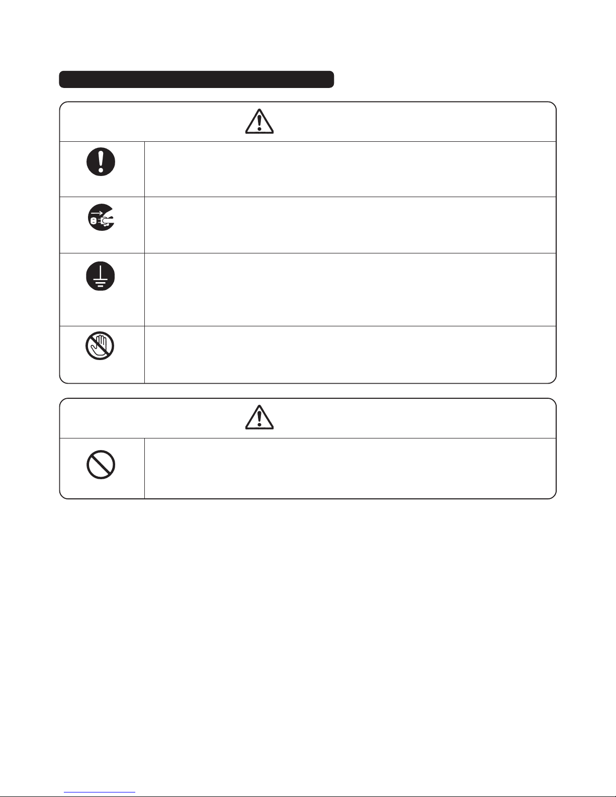
2. CAUTIONS FOR SAFETY
• Please observe the following important notes on safety.
• The notes mean as follows.
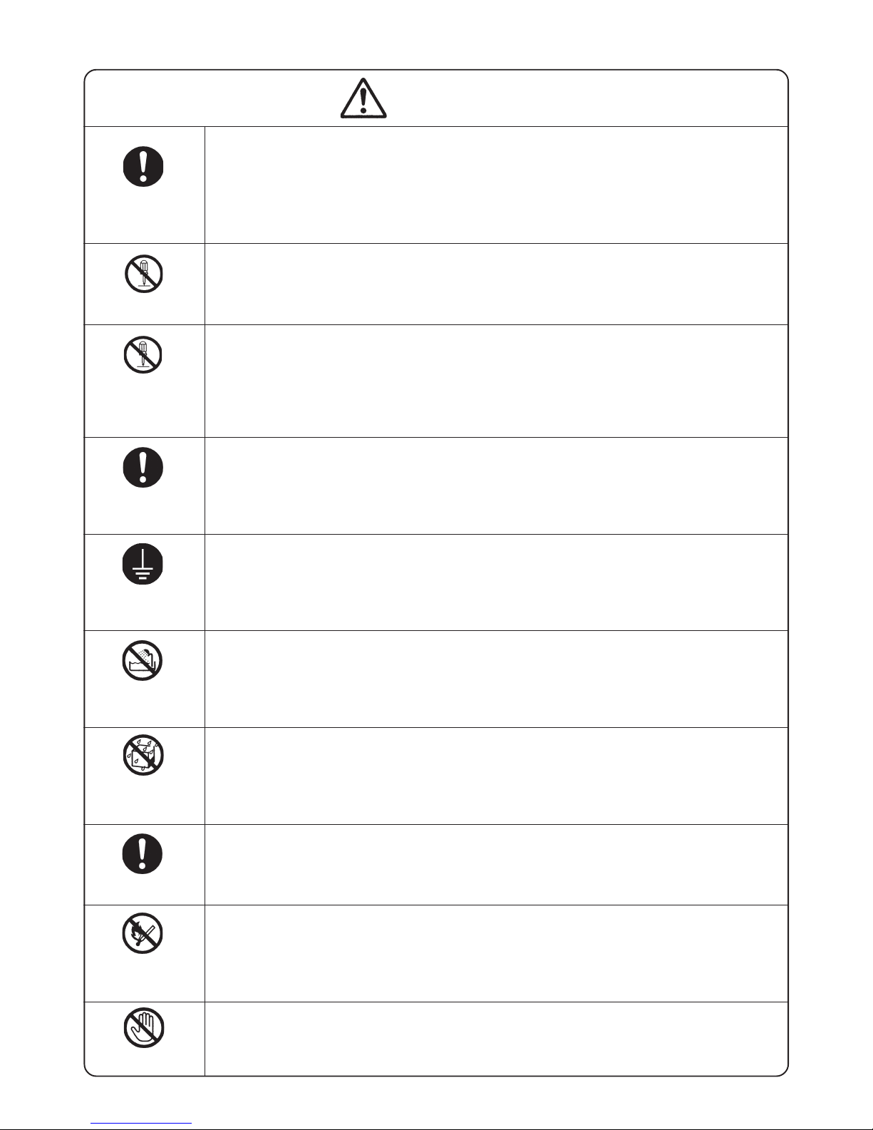
WARNING
Symbol
Meaning
CAUTION
Indicates possibility of death or serious injury of a repair technician and a person nearby
through the misconducted work, or of a user by a defect of the product after the work performed by the technician.
Indicates possibility of injury or physical damages* of a repair technician and a person nearby
through the misconducted work, or of a user by a defect of the product after the work performed by the technician.
ELECTRIC SHOCK
Graphic symbol Meaning
DO NOT
DISASSEMBLE
f indicates a caution (including a warning).
Specific instruction is followed by a graphic or characters in or near
f.
Symbol left warns an electric shock.
indicated prohibition (act must not be conducted).
Specific instruction is followed by a graphic or characters in or near .
Symbol left warns not to disassemble.
z indicates a forcing (act must be conducted).
Specific instruction is followed by a graphic or characters in or near
z.
Symbol left warns to unplug the power cord.
*
Means secondary damages of property, furniture, domestic animal and pet.
WARNING
x Advise the customer to keep children out of the work place.
Children may be injured with a tool or a disassembled part.
x Unplug the power cord for the work unnecessary to power on like disassembling. Do not
hold the plug by a wet hand.
Failing to unplug may cause an electric shock.
x Use the specified repair parts when repairing the product.
Otherwise, a malfunction or a defect may occur. Also, a short circuit, ignition or other danger
to the customer may occur.
Graphic Symbols
UNPLUG
OUT OF CHILD
UNPLUG POWER
USE
REPAIR PARTS
– 3 –
x After the end of working, measure insulation resistance between the charging part
(power cord plug) and the non-charging metallic part (ground) with an insulation
resistance meter (500 V) and check the resistance is 10 MΩ or more.
Failing to check the insulation resistance may cause a short circuit, an electric shock or other
diseases to the customer.
x Do not modify the product.
An electric shock or ignition may occur.
x Only a repair technician can disassemble and repair.
An electric shock, ignition or malfunction may cause injury.
x Use an exclusive 110 VAC/15 A socket for the washing machine.
x Use an exclusive 220 VAC/17 A socket for the washing machine. (Except above models)
Otherwise, an electric shock or ignition may cause. Sharing the same socket with other
instrument causes heating of a branch socket and result in a fire.
x Connect the grounding wire.
Failing to do so may cause an electric shock when a short circuit occurs.
Consult an electric work shop or a sales shop.
x Do not install in a bath room or a place exposed to wind or rain.
An electric shock or a short circuit may cause a fire.
x Do not pour or immerse the electrical parts.
An electric shock or ignition may occur.
x Wipe off the dust adhered to the plug of the power cord.
Dust may cause a fire.
x Do not put inflammable into washing tub.
Do not put cloths stained with kerosene, gasoline, benzene, thinner, alcohol. etc. It may cause
a fire or explosion.
x Do not touch the laundry before the spin basket stops completely.
The laundry entangles your hand causing an injury even if the basket rotates slowly.
Pay special attention to children.
CHECK INSULA-
TION RESISTANCE
DO NOT MODIFY
DO NOT
DISASSEMBLE
AND REPAIR
WARNING
USE EXCLUSIVE
SOCKET
CONNECT
GROUNDING WIRE
DO NOT USE
WET PLACE
DO NOT SPLASH
WATER
REMOVE DUST
AVOID INFLAM-
MABLE
DO NOT TOUCH
– 4 –
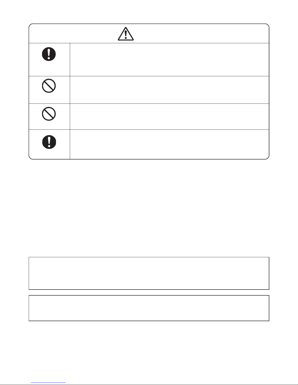
CAUTION
x Ask an electric work shop to install the product.
Install the product securely and safely according to the electrical equipment technical
standard and the wiring standard.
Incorrect work causes an electric shock and a fire.
x Do not pull the power cord when unplugging.
Hold the power plug to unplug.
An electric shock or short circuit may cause a fire.
x Do not insert your hand under the washing machine during operation.
There is a rotary part under the machine which may cause an injury.
x Before starting washing, open the faucet and check that the water supply hose joint is
not loose and no water leaks.
The loose screw or hose joint may cause water leakage resulting in an unexpected damage.
INSTALL
CAREFULLY
DO NOT PULL
DANGER HAND
WATER LEAKAGE
3. CAUTIONS FOR MICROCOMPUTER OPERATION
When changing the cycles or procedures of the operation on the way, the operation will not be changed even
if the START/HOLD button is pushed.
When changing the cycles or the procedures of the operation, please turn off the power switch and set them
again.
When the power switch is not turned on, the operation is not performed even if the clock display appears.
(When the clock display appears on the display panel, if may lead misunderstanding to control the operation.
But the operation is not performed in this condition.)
– 5 –
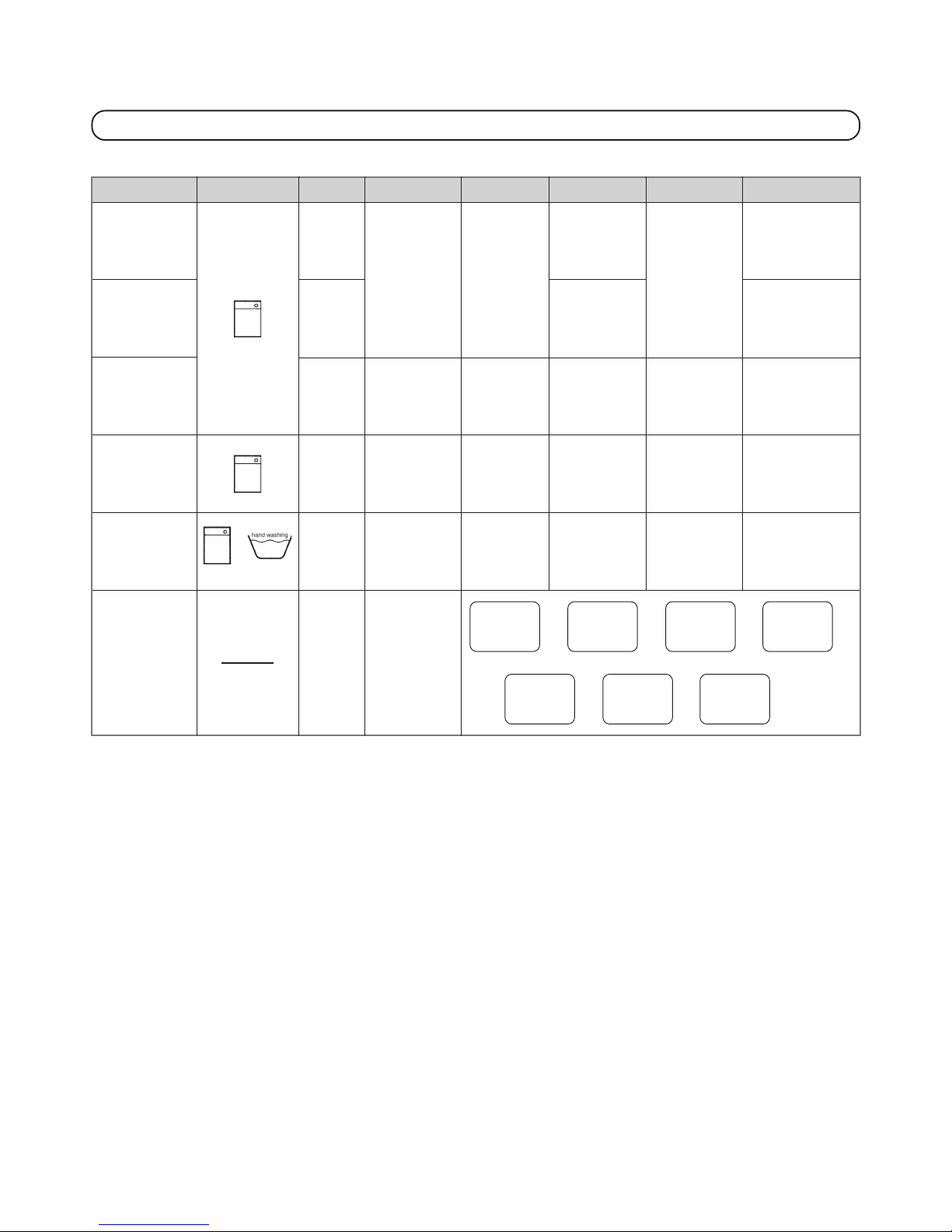
4. TECHNICAL POINT
4-1. EACH CYCLE SPECIFICATION
The asterisk (*) below denotes initial set-up.
• The time requirements listed above include a water supply rate of 15 L/min and a drainage time. The actual time required
varies according to the quality of the laundry, the degree of its offset, water pressure, and/or drainage status.
• Actual wash and spin may differ from operation time indicated by the process display.
• If load of the laundry is not balanced, the residual time may increase to correct this imbalance.
Object
Ordinary
Washing
Ordinary
Washing
Washing Heavily
Soiled Clothes
Washing Very
Dirty Clothes
Washing
Blankets
Cleaning the
Wash Basket
-
Supply of water
and rotation:
11 mins
-
Soaking in
water:
20 mins
-
Washing
:
3 mins
-
Draining and
spinning:
3 mins
-
Supply of water
and rotation:
11 mins
-
Rinsing:
3 mins
Draining and
spinning:
3 mins
Water Level
10L-51L
stepless
auto-setting
10L-51L
stepless
auto-setting
10L-51L
stepless
auto-setting
Display shows
“51L” The water
level becomes
higher than “51L”.
No indicator.
Depends on
water level
exceeding 51L.
Rinse
Shower rinsing
(2 times)
Static rinsing
(1 time)
Shower rinsing
(2 times)
Overflow rinsing
(1 time)
Shower rinsing
(2 times)
Static rinsing
(1 time)
Shower rinsing
(2 times)
Static rinsing
(1 time)
Overflow rinsing
(2 times)
Approx. Time Required
About 16 to
40 mins
About 20 to
47 mins
About 16 to
40 mins
About 1 hour
16 mins to
3 hours
38 mins
About 51 to
52 mins
Wash
*8 mins
Max: 10 mins
Min: 6 mins
*8 mins
Max: 10 mins
Min: 6 mins
8 mins
12 mins
Spin (Approx.)
*5 mins
Max: 6 mins
Min: 4 mins
*5 mins
Max: 6 mins
Min: 4 mins
6 mins
8 mins
(display is
9 mins)
Clothes-handling label
Course
Standard
Heavy
Rinse
Heavy
Wash
Soak
Blanket
Basket/
Tu b
Cleaning

– 6 –
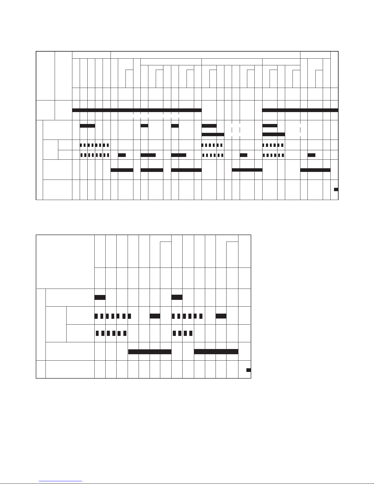
4-2. TIMER SEQUENCE CHART
*Unravel is operated as following at the last of wash or rinse.
Unravel operation
HIGH
MEDIUM
LOW
10"
10"
18"
UNRAVEL DRAIN
ROTAION
REVERSE
DRAIN VALVE
OUT PUT
MOTOR
WASH
RINSE SPIN
SCHOWER RINSE RINSE 1 RINSE 2
CYCLE
STANDARD
HEAVY RINSE
HEAVY WASH
WATER
LEVEL
Automatically
setting
(10L~51L)
Automatically
setting
(10L~51L)
Automatically
setting
(10L~51L)
Automatically
setting
(10L~51L)
Automatically
setting
(10L~51L)
Automatically
setting
(10L~51L)
Automatically
setting
(10L~51L)
Weight detect
Fill water
Amount detect
Preparatory
WATER CURRENT
DETECT
WASH
UNRAVEL
DRAIN
SPIN
PAUSE
BRAKE
Fill water
SPIN
PAUSE
BRAKE
Fill water
SPIN
PAUSE
BRAKE
Fill water
Preparatory
RINSE
UNRAVEL
DRAIN
SPIN
PAUSE
BRAKE
Fill water
Preparatory
RINSE
UNRAVEL
DRAIN
DRAIN
SPIN
PAUSE
BRAKE
BUZZER
Fill water
[
1'30"
4'~12"
[
1'34"
~
5'
10"
1'50"
~
4'34"
10" 10"
[
42"~
1'42"
[
2'~3'
34" 10"
[
42"~
1'42"
[ 10" 6"
42"~
3'14"
ROTATION
REVERSE
ROTATION
SELECT OPERATION (REGULAR CYCLE)
OUT PUT
WASH
only
RINSE
One
time
RINSE
two
times
RINSE
Three
times
SPIN
Only
MOTOR
INTAKE VALVE
static rinse
overflow rinse
static rinse
overflow rinse
DRAIN VALVE
5
"
9"~
1'11"
9"~
1'11"
1'~
9"
BLANKET
Automatically
setting (51L)
Mamual
setting (41L)
AUTO POWER
OFF
7'30" 6'34" 38" 4'34" 38" 102" 6'04"4'10"
7'30" 6'34" 38" 4'34" 38" 4'10"
6'04"
7'30" 6'34" 38" 4'34" 38" 102"4'10"
6'04"
*(Water level: 51L Water current : regular)
*(Water level: 51L Water current : regular)
*(Water level: 51L Water current : regular)
102" (80" fill water) 4'24" 102" (80" fill water)
11'50" 9' 6'10"
7'20"
3' fill water 3' fill water
*(Water level: 51)
↔
15"
– 7 –
SOAK COURSE
SOAK
RINSE SPIN
SCHOWER RINSE RINSE 1 RINSE 2
CYCLE
SOAK
WATER
LEVEL
Automatically
setting
(10L~51L)
Fill water
Amount detect
SOAK
WASH
UNRAVEL
DRAIN
SPIN
PAUSE
BRAKE
Fill water
SPIN
PAUSE
BRAKE
Fill water
SPIN
PAUSE
BRAKE
Fill water
Preparatory
RINSE
UNRAVEL
DRAIN
SPIN
PAUSE
BRAKE
Fill water
Preparatory
RINSE
UNRAVEL
DRAIN
DRAIN
SPIN
PAUSE
BRAKE
BUZZER
[
1'50"
~
4'34"
10" 10"
[
42"~
1'42"
[
2'~6'
10" 10"
[
42"~
1'42"
[ 10" 6"
2'20"~
4'10"
[
9"~
1'11"
9"~
1'11"
1'~
9"
7'30" 6'34" 38" 4'34" 38" 102" 6'04"4'10"
*(Water level: 51L Water current : regular)
ROTATION
REVERSE
ROTATION
OUT PUT
MOTOR
INTAKE VALVE
static rinse
overflow rinse
static rinse
overflow rinse
DRAIN VALVE
AUTO POWER
OFF
↔
15"
1'30"
1h~
3h"
10"~
18"
4'~
12'
1'50"~
4'34"
10"
TUB CLEAING COURSE
FILL WATER
SOAK
WASH
SPIN
DRAIN
SPIN
PAUSE
FILL WATER
RINSE
SPIN
DRAIN
SPIN
PAUSE
END
ROTATION
REVERSE
ROTATION
DRAIN VALVE
OUT PUT
MOTOR
INTAKE VALVE
[
20"
[ 20"[[
BUZZER
3' 50" 30" 20" 3' 50" 30"
↔
15"
AUTO POWER OFF
– 8 –
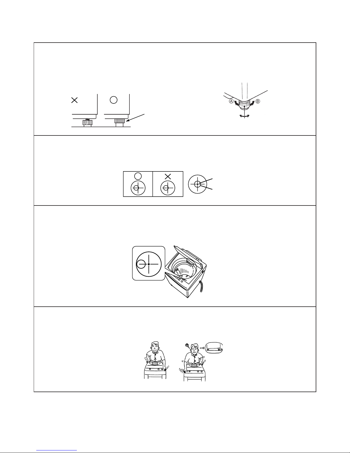
Adjust the legs so that the machine does not move.
1. After adjustment, lock the nuts of the legs by rotating them in the direction of the arrow (B).
Make sure so that the bottom of the main body front does not reach the floor.
If the bottom is in touch with the floor, then it will be the cause of shaking and abnormal noise.
Check the position of the air bubble in the floor level indicator.
2. If the bubble is not positioned inside the circle, adjust height by rotating the leg caps.
Depending on locations of the bubble in the horizontal level indicator, place caps and lock legs
(Make sure to fix adjustable legs.)
3. Mount the caps on the right-hand legs. Rotate the height adjust legs to perform height adjustments.
Hold down the diagonal line of the washing machine, and make sure that no wobbling occurs.
4.
Despite the fact that the bubble is inside the circle, if the wobbling exists. Then shaking motion becomes
larger or some abnormal noise comes out. Make sure to readjust in case the washing machine wobbles.
5. INSTALLATION
Circle
Note: Check the floor level
Indicator directly from above.
NOTE: The machine comes with four leg caps: two for adjustment in steps of 3 mm, and two for adjustment in
steps of 6 mm. Use them in combination as required. If they are to be stacked, position the thicker
caps under thinner ones.
Tighten nuts of adjustable
legs, and lock them.
Unlock Lock
Down
Height adjust leg
Up
(EX) The washing machine is tilted towards the right
Bubble
Ratting
Ratting
Ratting
– 9 –
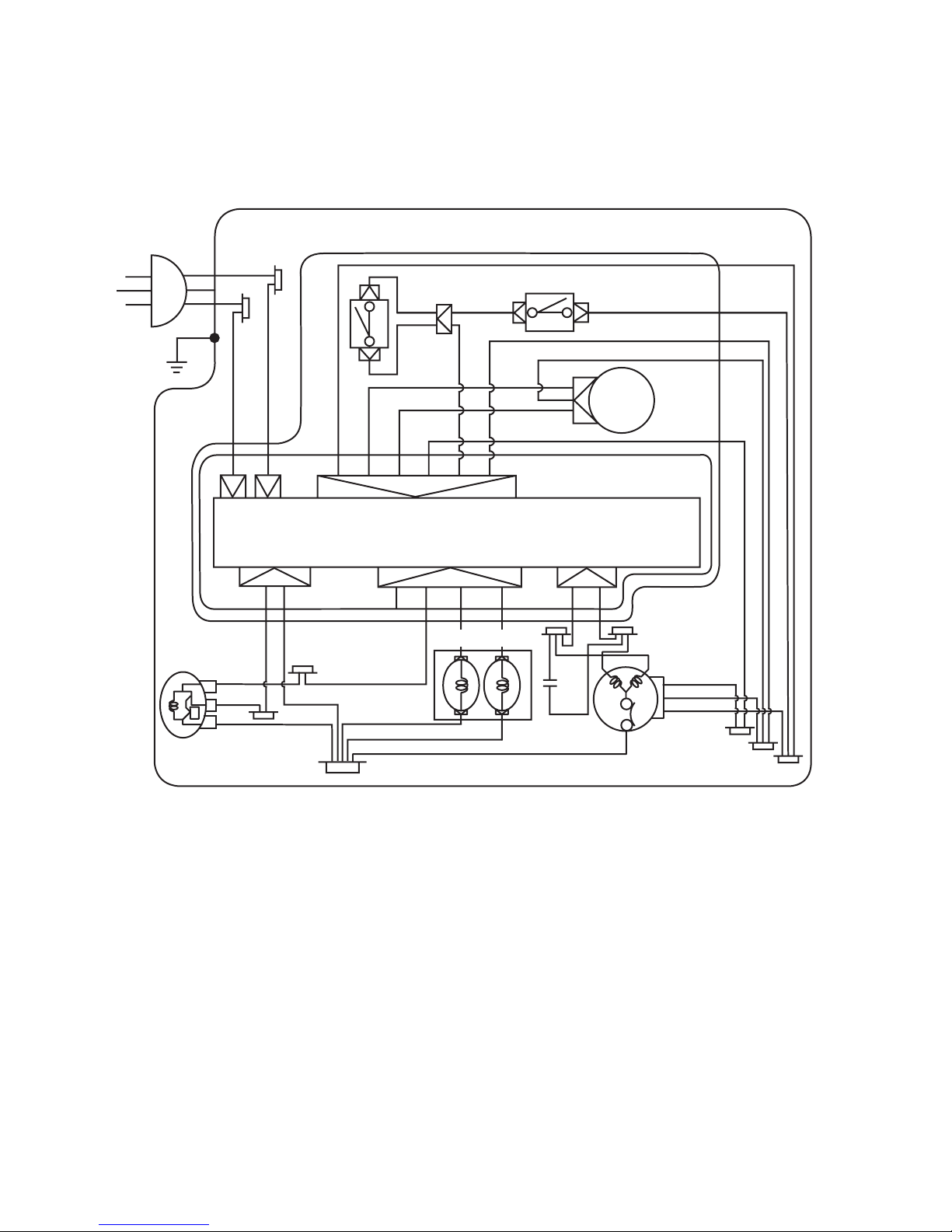
6. SCHEMATIC DIAGRAM
6-1. AW–9500S, AW–G9930S, AW–G1130S
CABINET
Y
2P
4P
2P
W
GY
OR
L.G.
WATER
LEVEL
SENSOR
BU
BU
GY
BU
BU
B
EARTH
BR
GY
G
PK
Y
V
R
PK
BL
MOTER
V
GY
GY
GY
R
BR BR
A.C.
SOURCE
B --- Black L.G --- Light Green PK --- Pink
BR --- Brown OR --- Orange
BU --- Blue R --- Red
GY --- Gray V --- Violet
G --- Green W --- White
L.B --- Light Blue Y --- Yellow
INTAKE VALVE
LID SWITCH
REED
SWITCH
PCB UNIT
6P
BR
L.B.
PK
GEARD MOTOR
PK
Y
BU
BR
– 10 –
7. CHECKING PROCEDURES
7-1. Warning and Caution at Troubleshooting
CAUTION
x Do not insert your hand under the washing machine during operation.
There is a rotary part under the machine which may cause an injury.
DANGER HAND
WARNING
x Advise the customer to keep children out of the work place.
Children may be injured with a tool or a disassembled part.
x Unplug the power cord for the work unnecessary to power on like disassembling.
Do not hold the plug by a wet hand.
Failing to unplug may cause an electric shock.
x Connect the grounding wire.
Failing to do so may cause an electric shock when a short circuit occurs.
Consult an electric work shop or a sales shop.
x Do not touch the laundry before the spin basket stops completely.
The laundry entangles your hand causing an injury even if the basket rotates slowly.
Pay special attention to children.
OUT OF CHILD
UNPLUG POWER
CONNECT
GROUNDING WIRE
DO NOT TOUCH
– 11 –
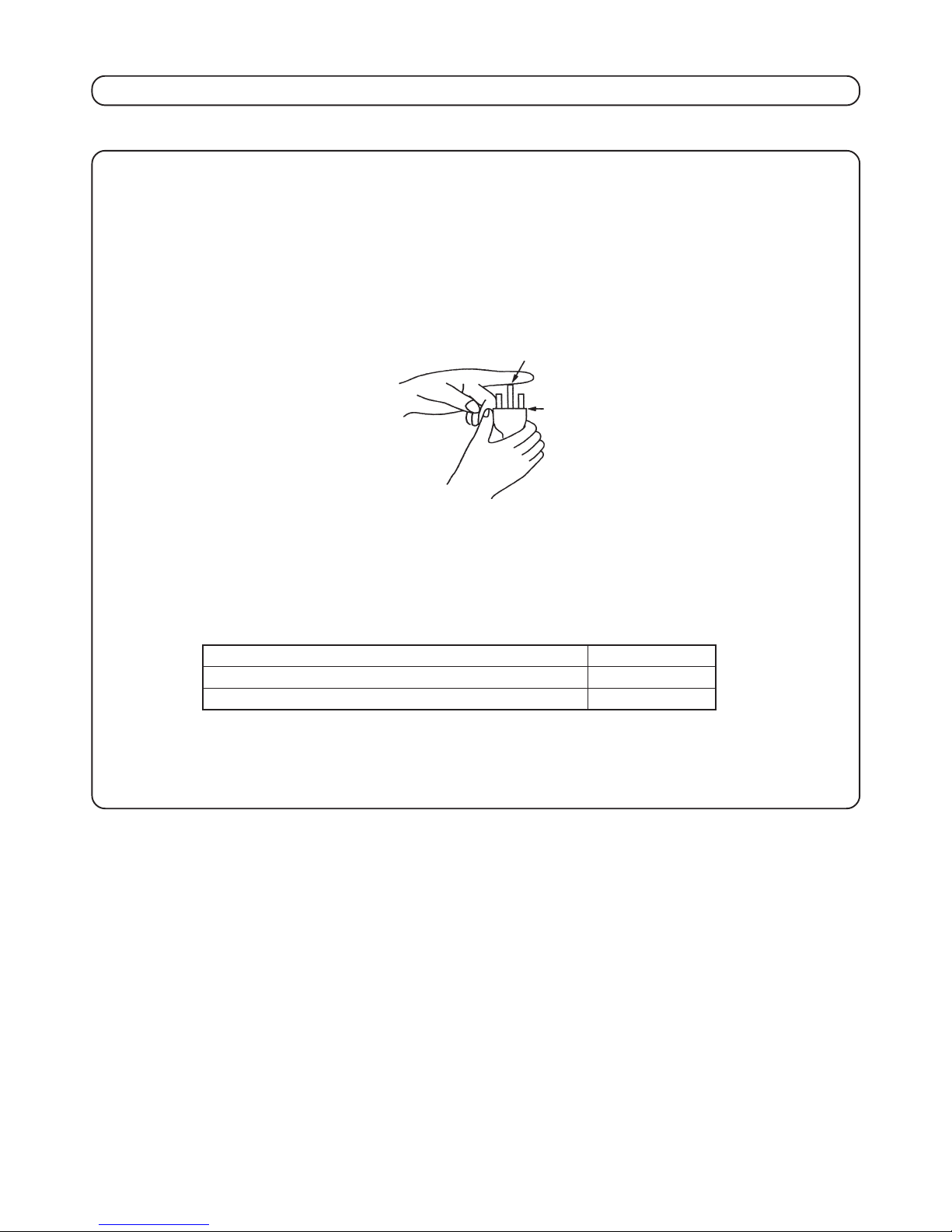
When checking trouble or repairing, keep to the following items.
(1)
Unplug the power cord and wait for 5 seconds before starting the operation (the capacitor of large
capacity is used).
(2) The static electricity charged on plastic parts of the machine or on the human body may cause damage to
the electronic parts. Wear a ground ring or touch the two short plug pins together and the ground wire or
ground pin once to discharge the electric potential difference between the human body and the washing
machine when repairing the program timer
(3) As program timer is covered by moistureproof coating, parts in the electronic timer can not be replaced.
Please change the whole unit of the program timer. Also, do not damage the moistureproof coating.
(4) As live high (see as below) and low (DC17 V) voltage are mixed inside the panel plate, pay attention not
to touch the parts.
(5) The radiator plate of the program timer is hot immediately after the operation. Take care not to suffer
burns.
Ground pin
Power plug
CAUTION ON REPAIRING AND/OR DISASSEMBLING
AW-9500SER / SB / SBK AC 230 - 240 V
AW-9500SBB / SBJ / SBX AC 220 V
AW-G9930S / G1130S AC 110 V
– 12 –
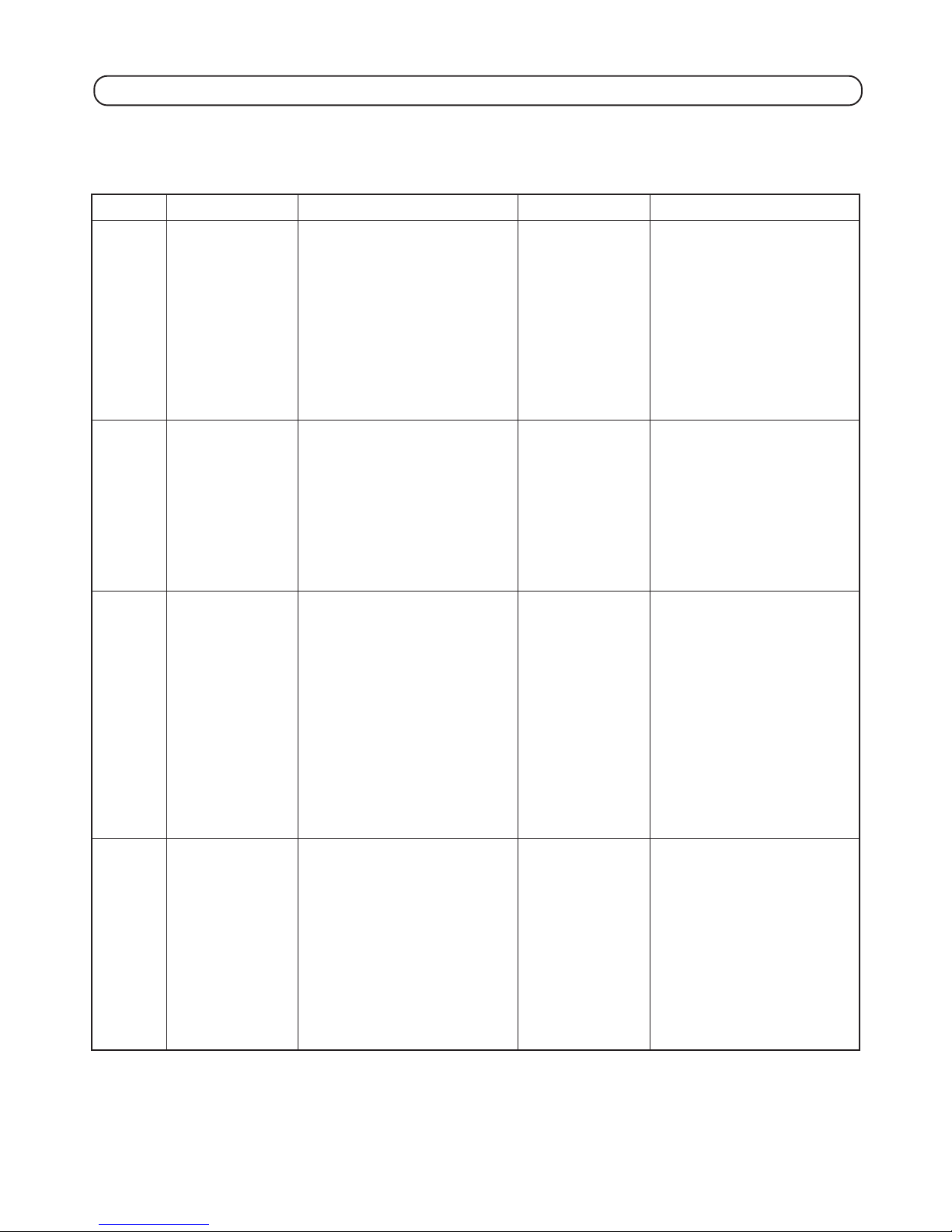
7-2. WARNING ALARM
(1) Failure symptoms
When something is wrong or accident with the washing machine like the operation error, the draining failure, the spinning
failure, warn the alarm and indicate the error to stop the cycle.
Indication
E 1
E 2
E 3
E3← →-1
E3← →-2
Flashing
alternately
E 5
Failure symptoms
DRAINING FAILURE
For 3 min. 40 sec. After
draining started, don’t
increase the water under
the reset level as draining.
LID OPENING FAILURE
During spinning or
shower rinsing the lid is
opening.
UNBALANCE FAILURE
When the unbalance
occurs more than 3
times.
WATER SUPPLY
FAILURE
Cause
Whether the drain hose collapses.
Whether the drain hose is thrown.
Whether the drain hose is frozen.
Whether the drain hose set right.
Whether the hose height more than
15 cm.
Whether the extension hose use more
than 3 m.
Whether the hose is extension.
Whether the drain hose end is soaked in
water.
Whether the lid open.
E3-1
Whether the clothes is unbalanced.
→ Correct it equally and start again.
Whether the washing machine lean.
→ Correct it at a level.
Whether the drain hose set right.
Whether the hose height more than
15 cm.
Whether the extension hose use more
than 3 m.
Whether the hose is extension.
E3-2
Whether the diagonosis are same as
“E-1”.
Whether the water faucet closes.
Whether the water supply is frozen or cut
off.
Whether the filter of the inlet valve clogs.
Remedy
Power switch OFF
→ ON,
or after the lid open
and close, press the
START/HOLD button.
The lid open and close
The lid open and close.
Power switch OFF
→ ON,
or after the lid open
and close, press the
START/HOLD button.
Countermeasure for failure
✩ Cofirm the operation of the drain
valve.
✩ Cofirm the connection and lead wire
of the drain valve connector and the
program timer.
✩ Confirm the water level sensor and
the air tube.
★ Replace the drain valve.
★ Replace the program timer.
★ Replace the water level sensor and
the air tube.
✩ Confirm the safety lever. (51 ± 3 mm)
✩ Confirm the operation of the lid
switch.
✩ Confirm the connection and lead
wire of the lid switch connector and
the program timer.
★ Replace the lid switch.
★ Replace the lid switch assembly.
★ Replace the program timer.
✩ Confirm the safety lever. (51 ± 3 mm)
✩ Confirm the connection and lead
wire of the lid switch connector and
the program timer.
✩ Confirm the operation of the stay.
★ Replace the lid switch assembly.
★ Replace the program timer.
★ Replace the stay.
✩ Clean the filter screen at the inlet
port.
✩ Confirm the connection and lead
wire of the inlet valve.
✩ Confirm the connection and lead
wire of the program timer.
★ Replace the inlet valve.
★ Replace the program timer.

– 13 –
After replacing the program timer, the drive assembly or the belt, check the weight sensor according to the procedure
described in page 37.
Indication
E 7
E7← →-1
E7← →-2
E7← →-3
E7← →-4
Flashing
alternately
E 9
E b
Failure symptoms
MOTOR FAILURE
Motor does not rotate
normally and reversly.
WATER LEAKAGE
FAILURE
Water lever sensor’s fre-
quency failure.
Drain valve’s water leak
failure.
AUTO OFF FAILURE
Power relay failure.
Cause
E7-1
Whether the motor does not rotate
normally at wash mode.
E7-2
Whether the motor does not rotate
reversely at wash mode.
E7-3
Whether the motor does not rotate at spin
mode.
E7-4
Whether the motor does not rotate at both
wash mode or spin only mode.
This error will be displayed when the water level becomes below the reset level at
the time of wash or rinse process.
Check whether water leaks from the tub
or drain valve or not.
This error will be displayed when the
power relay is not shutt off at the time of
auto power OFF.
Remedy
Power switch OFF
→ ON.
Power switch OFF
→ ON.
Unplug the power cord.
Countermeasure for failure
✩ Confirm the connection and lead
wire of the program timer.
✩ Confirm the connection and lead
wire of the motor and the revolution
sensor.
★ Replace the program timer.
★ Replace the motor.
★ Replace the revolution sensor.
★ Replace the lead wire unit.
✩ Confirm the connection and lead
wire of the water level sensor.
✩ Confirm the connection and lead
wire of the program timer.
✩ Confirm the air tube.
✩ Confirm the operation of the drain
valve.
✩ Fill the water and check whether
leakage is observed or not.
✩ Check the wahing machine
according to the [Trouble shooting
of the water level sensor.
→ See page 17.
★ Replace the water level sensor.
★ Replace the program timer.
★ Replace the drain valve.
★ Connect the power plug and press
button again. (Do not press the start
button.) “Eb” will be displayed after
10 seconds.
Replace the program timer.
→
– 14 –
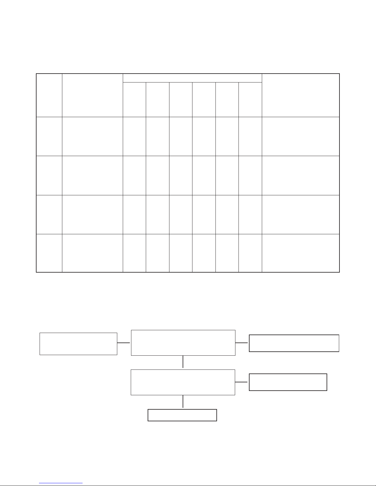
(2) Failure diagnosis with E7 failure error message
The E7 error message is classified into E7-1 to E7-4, moreover each massage is shown with digital display flashing alternately.
So, perform the failure diagnosis by reffering to the massage obtained in the field. If the massage is not clear, perform the
same diagnosis as in the E7-4.
Indication
1
E 7-1
2
E 7-2
3
E 7-3
4
E 7-4
Detail of abnormality
detected
Forward rotation not
obtained in motor
washing. (Inverse rotation
is normal operation.)
Inverse rotation not
obtained in motor
washing. (Forward
rotation is normal
operation.)
No rotation only in motor
spinning. (Washing is
normal).
Motor not rotate. Rotation
sensor no signal.
Failure location suspected
Program timer
Motor
Sensor case
assy
Lead wire unit
Capacitor
Drive assy
(include clutch
spring)
Failure diagnosis method
Diagnosis is according to the
procedure 1.
Diagnosis is according to the
procedure 2.
Diagnosis is according to the
procedure 3.
Diagnosis is according to the
procedure 4.
Note 1
•••
••
••
••••••
* In the failure diagnosis, timer failure or failures other than the timer will be determined by using the inspection mode under
“Program timer detailed failure diagnosis method”.
Diagnosis procedure for each error message
1 E 7 - 1
:
:
:
:
:
Perform Inspection mode setting
procedure 1) and 2). (Setting to
standby status.)
Check voltage across CN1 black and CN4 blue
in the standby status.
Is AC 220 V* obtained?
No
Ye s
Lead wire unit connector disconnected
or lead wire breakdown
Press the COURSE button to set motor normal
rotation mode, and check the above voltage.
Does voltage change from AC 220 V*→ 0 V?
Ye s
No
Forward rotation side of drive
assembly is locked.
*: It should be each rated voltage.
Program timer failure
– 15 –
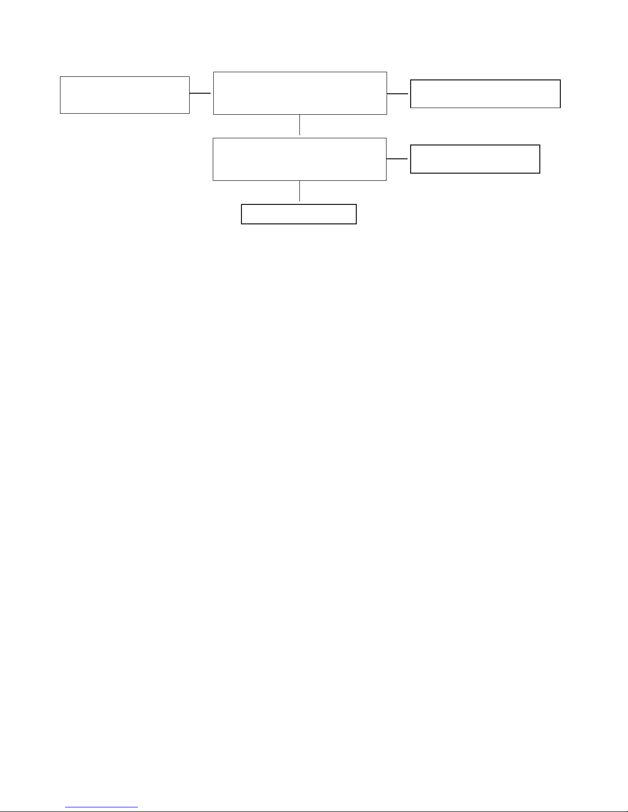
:
:
:
:
:
Perform Inspection mode setting
procedure 1) and 2). (Setting to
standby status.)
Check voltage across CN1 black and CN4
violet in the stanby status.
Is AC 220 V* obtained?
No
Ye s
Lead wire unit connector disconnected
or lead wire breakdown
Press the PRESET button to set motor inverse
rotation mode, and check the above voltage.
Does voltage change from AC 220 V*→ 0 V?
Ye s
No
No abnormality
Program timer failure
*: It should be each rated voltage.
2 E 7 - 2
3 E 7 - 3
If this indication displayed, the program timer, sensor case assembly and the lead wire unit are normal, and only the
lock in the spinning mode will be suspected. So, check the drive assembly (bearing shaft mechanism section, parts
associated with brake) and repair.
Note 1: The overload protection device may work during the water spinning operation and this may stop the motor.
In such case, cool the motor once and then check the operation again.
And check the power source (AC 220 V*).
*: It should be each rated voltage.
 Loading...