


User’s Manual
A210 Series
computers.toshiba-europe.com

A210 Series
Copyright
Disclaimer
© 2007 by TOSHIBA Corporation. All rights reserved. Under the copyright
laws, this manual cannot be reproduced in any form without the prior
written permission of TOSHIBA. No patent liability is assumed, with respect
to the use of the information contained herein.
TOSHIBA A210 Series Portable Personal Computer User’s Manual
First edition August 2007
Copyright authority for music, movies, computer programs, data bases and
other intellectual property covered by copyright laws belongs to the author
or to the copyright owner. Copyrighted material can be reproduced only for
personal use or use within the home. Any other use beyond that stipulated
above (including conversion to digital format, alteration, transfer of copied
material and distribution on a network) without the permission of the
copyright owner is a violation of copyright or author’s rights and is subject to
civil damages or criminal action. Please comply with copyright laws in
making any reproduction from this manual.
This manual has been validated and reviewed for accuracy. The
instructions and descriptions it contains are accurate for the TOSHIBA
A210 Series Portable Personal Computer at the time of this manual’s
production. However, succeeding computers and manuals are subject to
change without notice. TOSHIBA assumes no liability for damages incurred
directly or indirectly from errors, omissions or discrepancies between the
computer and the manual.
Trademarks
IBM is a registered trademark, and IBM PC and PS/2 are trademarks of
International Business Machines Corporation.
AMD, the AMD Arrow logo, AMD Athlon, AMD Turion, Radeon, and
combinations thereof, ATI Mobility Radeon are trademarks of Advanced
Micro Devices, Inc.
Windows and Microsoft are registered trademarks and Windows Vista is a
trademark of Microsoft Corporation.
Photo CD is a trademark of Eastman Kodak.
Memory Stick is a registered trademark and i.LINK is a trademark of
SonyCorporation.
Bluetooth is a registered trademark owned by its proprietor and used by
TOSHIBA under license.
DVD MovieFactory is trademarks of the Ulead Systems. Inc.
Labelflash™ is a trademark of YAMAHA CORPORATION.
Manufactured under license from Dolby Laboratories.
“Dolby” and the double-D symbol are trademarks of Dolby Laboratories.
ii User’s Manual

Confidential unpublished works. Copyright 1992-1997 Dolby Laboratories.
All rights reserved.
Manufactured under license from Digital Theater Systems, Inc. U.S. Pat.
No’s. 5,451,942; 5,956,674; 5,974,380; 5,978,762; 6,226,616; 6,487,535
and other U.S. and world-wide patents issued and pending. “DTS” and
“DTS Digital Surround” are registered trademarks of Digital Theater
Systems, Inc. Copyright 1996, 2003 Digital Theater Systems, Inc. All Rights
Reserved.
Other trademarks and registered trademarks not listed above may be used
in this manual.
Macrovision License of Notice
This product incorporates copyright protection technology that is protected
by U.S. patents and other intellectual property rights. Use of this copyright
protection technology must be authorized by Macrovision, and is intended
for home and other limited viewing uses only unless authorized by
Macrovision. Reverse engineering of disassembly is prohibited.
Safety Instructions
Use the following safety guidelines to help protect yourself and your
computer.
A210 Series
When Using Your Computer
Do not operate your portable computer for an extended period of time with
the base resting directly on your body. With extended operation, heat can
potentially build up in the base. Allowing sustained contact with the skin
could cause discomfort or, eventually, a burn.
■ Do not attempt to service the computer yourself. Always follow
installation instructions closely.
■ Do not carry a battery in your pocket, purse, or other container where
metal objects (such as car keys) could short-circuit the battery
terminals. The resulting excessive current follow can cause extremely
high temperatures and may result in damage from burns.
■ Be sure that noting rests on your AC adapter’s power cable and that the
cable is not located where it can be tripped over or stepped on.
■ Place the AC adapter in a ventilated area, such as a desk top or on the
floor, when you use it to run the computer or to charge the battery. Do
not cover the AC adapter with papers or other items that will reduce
cooling; also, do not use the AC adapter while it is inside a carrying
case.
■ Use only the AC adapter and batteries that are approved for use with
this computer. Use of another type of battery or AC adapter may risk fire
or explosion.
User’s Manual iii

A210 Series
■ Before you connect the computer to a power source, ensure that the
voltage rating of the AC adapter matches that of the available power
source. 115 V/60 Hz in most of North and South America and some Far
Eastern countries such as Taiwan. 100 V/50 Hz in eastern Japan and
100 V/60 Hz in western Japan. 230 V/50 Hz in most of Europe, the
Middle East, and the Far East.
■ If you use an extension cable with your AC adapter, ensure that the total
ampere rating of the products plugged in to the extension cable does
not exceed the ampere rating of the extension cable.
■ To remove power from the computer, turn it off, remove the battery, and
disconnect the AC adapter from the electrical outlet.
■ To help avoid the potential hazard of electric shock, do not connect or
disconnect any cables or perform maintenance or reconfiguration of this
product during an electrical storm.
■ When setting up the computer for work, place it on a level surface.
Working environment
This product was designed to fulfill the EMC (Electromagnetic
Compatibility) requirements for “residential, commercial and light industry
environments”.
The following environment is not approved:
■ In the following environments the use of this product can be restricted:
■ Industrial Environments (e.g. environments where a mains voltage
of 380V three-phase is being used).
■ Medical Environments: This product is not certified as a medical
product according to the Medical Product Directive 93/42/EEC, but
can be used in office areas where the use is not restricted. Please
disable the wireless LAN or Bluetooth hardware in such areas as
long this feature is not official supported by the operator of the
related medical facility.
■ Vehicle Environments: Please read the operator’s manual of the
vehicle manufacturer for further restrictions of use.
■ Aircraft Environments: Please follow the advices of the flight
personnel regarding restrictions of use.
■ Any consequences resulting from the use of this product in working
environments that are not approved or the use is restricted are not the
responsibility of Toshiba Corporation. The consequences of the use of
this product in those working environments may be:
■ Interference with other devices or machines in the nearby
surrounding area
■ Malfunction of, or data loss from, this product caused by
disturbances generated by other devices or machines in the nearby
surrounding area
Furthermore, for general safety reasons, the use of this product in
environments with explosive atmospheres is not permitted.
iv User’s Manual

EU Declaration of Conformity
This product is labelled with the CE Mark in accordance with Radio
Equipment and Telecommunications Terminal Equipment Directive
1999/5/EC which includes the compliance to the Electromagnetic
Compatibility Directive 2004/108/EC and the Low Voltage Directive
2006/95/EC.
CE Marking is the responsibility of TOSHIBA EUROPE GmbH,
Hammfelddamm 8, 41460 Neuss, Germany, phone +49-(0)-2131-158-01.
For a copy of the related CE Declaration of Conformity please refer to the
following website: http://epps.toshiba-teg.com
This product and the supplied accessories are designed to observe the
required EMC (Electromagnetic Compatibility) standards. However,
Toshiba cannot guarantee that this product still observes these EMC
standards if accessories or cables not manufactured / distributed by
Toshiba are connected or implemented. To avoid in general EMC problems,
the following advice should be observed:
■ Only CE marked accessories should be connected / implemented
■ Only best shielded data cables should be connected
GOST
A210 Series
User’s Manual v

A210 Series
Modem warning notice
Conformity Statement
The equipment has been approved to [Commission Decision “CTR21”] for
pan-European single terminal connection to the Public Switched Telephone
Network (PSTN).
However, due to differences between the individual PSTNs provided in
different countries/regions the approval does not, of itself, give an
unconditional assurance of successful operation on every PSTN network
termination point.
In the event of problems, you should contact your equipment supplier in the
first instance.
Network Compatibility Statement
This product is designed to work with, and is compatible with the following
networks. It has been tested to and found to conform with the additional
requirements conditional in EG 201 121.
Germany ATAAB AN005,AN006,AN007,AN009,AN010 and
Greece ATAAB AN005,AN006 and GR01,02,03,04
Portugal ATAAB AN001,005,006,007,011 and
Spain ATAAB AN005,007,012, and ES01
Switzerland ATAAB AN002
All other countries/
region
DE03,04,05,08,09,12,14,17
P03,04,08,10
ATAAB AN003,004
Specific switch settings or software setup are required for each network,
please refer to the relevant sections of the user guide for more details.
The hookflash (timed break register recall) function is subject to separate
national type approvals. It has not been tested for conformity to national
type regulations, and no guarantee of successful operation of that specific
function on specific national networks can be given.
Following information is only for EU-member states:
The symbol indicates that this product may not be treated as household
waste. Please ensure this product is properly disposed as inappropriate
waste handling of this product may cause potential hazards to the
environment and human health. For more detailed information about
recycling of this product, please contact your local city office, your
household waste disposal service or the shop where you purchased the
product.
This symbol may not stick depending on the country and region where you
purchased.
vi User’s Manual

Important Notice
Copyrighted works including, but not limited to music, video, computer
program, databases are protected by copyright laws. Unless specifically
permitted under applicable copyright laws, you cannot copy, modify, assign,
transmit or otherwise dispose of any copyrighted work with the consent of
the owner of the copyright. Please take notice that unauthorized copying,
modification, assignment, transmission and disposition may be subject to
claims for damages and penalties.
■ Avoid using a telephone (other than a cordless type) during an electrical
storm. There may be a remote risk of electric shock from lightning.
■ Do not use the telephone to report a gas leak in the vicinity of the leak.
■ Use only the power cord indicated in this manual.
■ Replace only with the same or equivalent type battery recommended by
the manufacturer.
■ Dispose of used batteries according to the manufacturer’s instructions
Use only the battery pack that came with the computer or an optional
battery pack. Use of wrong battery could damage your computer.
.
TOSHIBA assumes no liability for any damage in such case.
Optical disc drive standards
A210 Series
TOSHIBA A210 Series computer is shipped with one of the following drives
preinstalled: DVD-ROM, CD-RW/DVD-ROM, DVD Super Multi (+-R DL),
HD DVD-ROM, HD DVD-R or HD DVD-RW drive.
The drive has one of the following labels:
CLASS 1 LASER PRODUCT
LASER KLASSE 1
LUOKAN 1 LASERLAITE
APPAREIL A LASER DE CLASSE1
KLASS 1 LASER APPARAT
Before it is shipped, the Class 1 Laser is certified to meet the United States
Chapter 21 Standards of the Department of Health and Human Services
(DHHS 21 CFR).
For any other country, the drive is certified to meet the Class 1 Laser
standards of IEC825 and EN60825.
User’s Manual vii
A210 Series
DVD Super Multi (+-R DL) drive safety instructions
■ The drive employs a laser system. To ensure proper use of this
product, please read this instruction manual carefully and retain for
future reference.
Should the unit ever require maintenance, contact an authorized
service location.
■ Use of controls, adjustments or the performance of procedures other
than those specified may result in hazardous radiation exposure.
■ To prevent direct exposure to the laser beam, do not try to open the
enclosure.
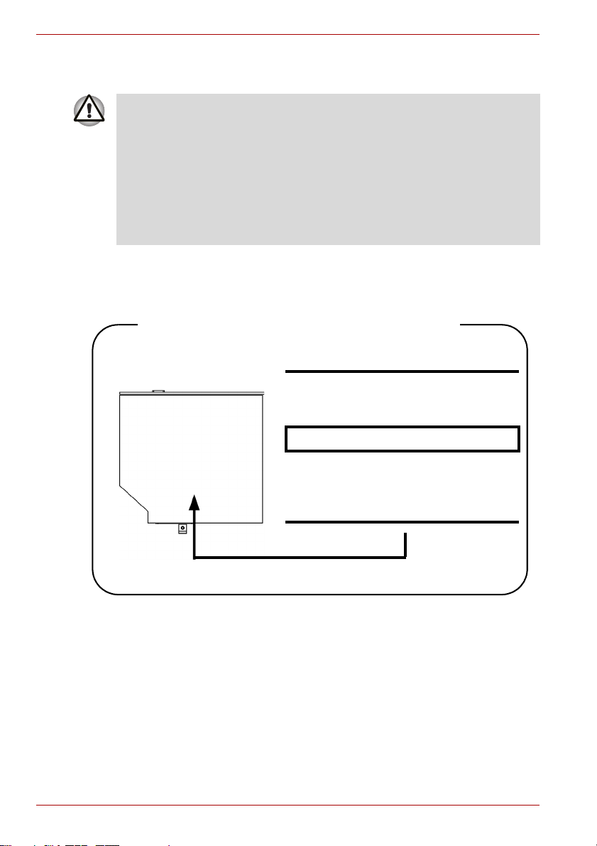
Matsushita UJ-850U
Location of the required label
COMPLIES WITHFDA RADIATION
PERFORMANCE STANDARDS, 21
CFR SUBCHAPTER J.
MANUFACTURED:
Manufactured by
Panasonic Communications Co.,
LTD 1-62, 4-Chome, Minoshima,
Hakata-ku, Fukuoka, JAPAN
viii User’s Manual
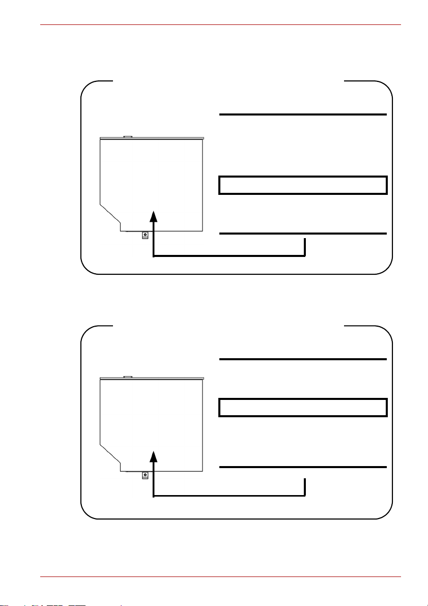
TEAC DV-W28E
Location of the required label
HLDS GSA-T20N
A210 Series
CERTIFICATION TISH PRODUCT
COMPLIES WITH DHHS RULES 21
CFR CHAPTER 1, SUBCHAPTER J
APPLICABLE DATE OF MANUFACTURE
MANUFACTURED:
TEAC CORPORATION
3-7-3 NAKA-CHO, MUSASHINO-SHI,
TOKYO, JAPAN
Location of the required label
COMPLIES WITHFDA RADIATION
PERFORMANCE STANDARDS, 21
CFR SUBCHAPTER J.
MANUFACTURED:
Manufactured by
Panasonic Communications Co.,
LTD 1-62, 4-Chome, Minoshima,
Hakata-ku, Fukuoka, JAPAN
User’s Manual ix

A210 Series
Pioneer DVR-K17T
Location of the required label
Toshiba Samsung TS-L632D
COMPLIES WITHFDA RADIATION
PERFORMANCE STANDARDS, 21
CFR SUBCHAPTER J.
MANUFACTURED:
Manufactured by
PIONEER CORPORATION 4-1.
Meguro 1-chome, Meguro-ku
TOKYO 153-8654, JAPAN
Location of the required label
PRODUCT IS CERTIFIED BY THE
MANUFACTURER TO COMPLY WITH
DHHS RULES 21 CFR SUBCHAPTER
J APPLICABLE AT THE DATE OF
MANUFACTURE.
MANUFACTURED:
TOSHIBA SAMSUNG STORAGE
TECHNOLOGY CORPORATION 580,
HORIKAWA-CHO, SAIWAI-KU,
KAWASAKI-SHI, KANAGAWA,
212- 0013, JAPAN
x User’s Manual

International Precautions
A210 Series
CAUTION: This appliance contains a laser
system and is classified as a “CLASS 1 LASER
PRODUCT.” To use this model properly, read
the instruction manual carefully and keep this
manual for your future reference. In case of
any trouble with this model, please contact
your nearest “AUTHORIZED service station.”
To prevent direct exposure to the laser beam,
do not try to open the enclosure.
CAUTION: USE OF CONTROLS OR
ADJUSTMENTS OR PERFORMANCE OF
PROCEDURES OTHER THAN THOSE
SPECIFIED IN THE OWNER’S MANUAL MAY
RESULT IN HAZARDOUS RADIATION
EXPOSURE.
User’s Manual xi

A210 Series
xii User’s Manual

Table of Contents
Preface
General Precautions
Chapter 1 Introduction
Equipment checklist. . . . . . . . . . . . . . . . . . . . . . . . . . . . . . . . . . . . . . . 1-1
Features. . . . . . . . . . . . . . . . . . . . . . . . . . . . . . . . . . . . . . . . . . . . . . . . . 1-3
Special Features . . . . . . . . . . . . . . . . . . . . . . . . . . . . . . . . . . . . . . . . . . 1-7
TOSHIBA Value Added Package . . . . . . . . . . . . . . . . . . . . . . . . . . . . . 1-9
Utilities and Application. . . . . . . . . . . . . . . . . . . . . . . . . . . . . . . . . . . 1-10
Options . . . . . . . . . . . . . . . . . . . . . . . . . . . . . . . . . . . . . . . . . . . . . . . . 1-12
Chapter 2 The Grand Tour
Front with the display closed . . . . . . . . . . . . . . . . . . . . . . . . . . . . . . . 2-1
Left side. . . . . . . . . . . . . . . . . . . . . . . . . . . . . . . . . . . . . . . . . . . . . . . . . 2-3
Right side . . . . . . . . . . . . . . . . . . . . . . . . . . . . . . . . . . . . . . . . . . . . . . . 2-5
Back side. . . . . . . . . . . . . . . . . . . . . . . . . . . . . . . . . . . . . . . . . . . . . . . . 2-6
Underside . . . . . . . . . . . . . . . . . . . . . . . . . . . . . . . . . . . . . . . . . . . . . . . 2-6
Front with the display open. . . . . . . . . . . . . . . . . . . . . . . . . . . . . . . . . 2-7
System indicators. . . . . . . . . . . . . . . . . . . . . . . . . . . . . . . . . . . . . . . . . 2-9
Keyboard indicators. . . . . . . . . . . . . . . . . . . . . . . . . . . . . . . . . . . . . . 2-10
Optical disc drive . . . . . . . . . . . . . . . . . . . . . . . . . . . . . . . . . . . . . . . . 2-11
AC adaptor . . . . . . . . . . . . . . . . . . . . . . . . . . . . . . . . . . . . . . . . . . . . . 2-13
Chapter 3 Getting Started
Connecting the AC adaptor . . . . . . . . . . . . . . . . . . . . . . . . . . . . . . . . . 3-2
Opening the display . . . . . . . . . . . . . . . . . . . . . . . . . . . . . . . . . . . . . . . 3-3
Turning on the power . . . . . . . . . . . . . . . . . . . . . . . . . . . . . . . . . . . . . . 3-3
Starting up for the first time . . . . . . . . . . . . . . . . . . . . . . . . . . . . . . . . 3-4
Turning off the power. . . . . . . . . . . . . . . . . . . . . . . . . . . . . . . . . . . . . . 3-4
Restarting the computer . . . . . . . . . . . . . . . . . . . . . . . . . . . . . . . . . . . 3-7
System Recovery Options . . . . . . . . . . . . . . . . . . . . . . . . . . . . . . . . . . 3-8
A210 Series
User’s Manual xiii

A210 Series
Chapter 4
Operating Basics
Using the Touch Pad . . . . . . . . . . . . . . . . . . . . . . . . . . . . . . . . . . . . . . .4-1
Using optical disc drives. . . . . . . . . . . . . . . . . . . . . . . . . . . . . . . . . . . .4-2
Writing CD/DVDs on DVD Super Multi (+-R DL) drive. . . . . . . . . . . . .4-6
Media care. . . . . . . . . . . . . . . . . . . . . . . . . . . . . . . . . . . . . . . . . . . . . . .4-14
Using the Web Camera . . . . . . . . . . . . . . . . . . . . . . . . . . . . . . . . . . . .4-15
Using the microphone . . . . . . . . . . . . . . . . . . . . . . . . . . . . . . . . . . . . .4-17
Modem. . . . . . . . . . . . . . . . . . . . . . . . . . . . . . . . . . . . . . . . . . . . . . . . . .4-17
Wireless communications . . . . . . . . . . . . . . . . . . . . . . . . . . . . . . . . . .4-20
LAN . . . . . . . . . . . . . . . . . . . . . . . . . . . . . . . . . . . . . . . . . . . . . . . . . . . .4-22
Cleaning the computer . . . . . . . . . . . . . . . . . . . . . . . . . . . . . . . . . . . .4-24
Moving the computer. . . . . . . . . . . . . . . . . . . . . . . . . . . . . . . . . . . . . .4-24
Heat dispersal. . . . . . . . . . . . . . . . . . . . . . . . . . . . . . . . . . . . . . . . . . . .4-25
Chapter 5 The Keyboard
Typewriter keys . . . . . . . . . . . . . . . . . . . . . . . . . . . . . . . . . . . . . . . . . . .5-1
F1 ... F12 function keys . . . . . . . . . . . . . . . . . . . . . . . . . . . . . . . . . . . . .5-2
Soft keys: FN key combinations . . . . . . . . . . . . . . . . . . . . . . . . . . . . . .5-2
Windows special keys . . . . . . . . . . . . . . . . . . . . . . . . . . . . . . . . . . . . . .5-5
Keypad overlay. . . . . . . . . . . . . . . . . . . . . . . . . . . . . . . . . . . . . . . . . . . .5-5
Generating ASCII characters. . . . . . . . . . . . . . . . . . . . . . . . . . . . . . . . .5-7
Chapter 6 Power and Power-Up Modes
Power conditions . . . . . . . . . . . . . . . . . . . . . . . . . . . . . . . . . . . . . . . . . .6-1
Power indicators . . . . . . . . . . . . . . . . . . . . . . . . . . . . . . . . . . . . . . . . . .6-3
Battery . . . . . . . . . . . . . . . . . . . . . . . . . . . . . . . . . . . . . . . . . . . . . . . . . . .6-4
Care and use of the battery pack . . . . . . . . . . . . . . . . . . . . . . . . . . . . .6-5
Replacing the battery pack . . . . . . . . . . . . . . . . . . . . . . . . . . . . . . . . .6-12
TOSHIBA Password Utility . . . . . . . . . . . . . . . . . . . . . . . . . . . . . . . . .6-14
Power-up modes . . . . . . . . . . . . . . . . . . . . . . . . . . . . . . . . . . . . . . . . .6-15
Panel power on/off . . . . . . . . . . . . . . . . . . . . . . . . . . . . . . . . . . . . . . . .6-15
System Auto Off . . . . . . . . . . . . . . . . . . . . . . . . . . . . . . . . . . . . . . . . . .6-15
Chapter 7 HW Setup and Passwords
HW Setup . . . . . . . . . . . . . . . . . . . . . . . . . . . . . . . . . . . . . . . . . . . . . . . .7-1
Chapter 8 Optional Devices
Express Card . . . . . . . . . . . . . . . . . . . . . . . . . . . . . . . . . . . . . . . . . . . . .8-2
Multiple Digital Media Card Slot . . . . . . . . . . . . . . . . . . . . . . . . . . . . . .8-4
Memory expansion. . . . . . . . . . . . . . . . . . . . . . . . . . . . . . . . . . . . . . . . .8-7
Additional battery pack (6 Cell and 9 Cell). . . . . . . . . . . . . . . . . . . . .8-10
Additional AC adaptor . . . . . . . . . . . . . . . . . . . . . . . . . . . . . . . . . . . . .8-10
USB FDD Kit . . . . . . . . . . . . . . . . . . . . . . . . . . . . . . . . . . . . . . . . . . . . .8-10
External monitor. . . . . . . . . . . . . . . . . . . . . . . . . . . . . . . . . . . . . . . . . .8-10
Television . . . . . . . . . . . . . . . . . . . . . . . . . . . . . . . . . . . . . . . . . . . . . . .8-11
i.LINK (IEEE1394) . . . . . . . . . . . . . . . . . . . . . . . . . . . . . . . . . . . . . . . . .8-11
xiv User’s Manual

A210 Series
Chapter 9
Troubleshooting
Problem solving process. . . . . . . . . . . . . . . . . . . . . . . . . . . . . . . . . . . 9-1
Hardware and system checklist . . . . . . . . . . . . . . . . . . . . . . . . . . . . . 9-3
TOSHIBA support . . . . . . . . . . . . . . . . . . . . . . . . . . . . . . . . . . . . . . . . 9-17
Chapter 10 Disclaimers
Appendix A Specifications
Appendix B Display Controller and Modes
Display controller . . . . . . . . . . . . . . . . . . . . . . . . . . . . . . . . . . . . . . . . . B-1
Video Modes . . . . . . . . . . . . . . . . . . . . . . . . . . . . . . . . . . . . . . . . . . . . . B-2
Appendix C V.90/V.92
V.90/V.92 mode . . . . . . . . . . . . . . . . . . . . . . . . . . . . . . . . . . . . . . . . . . . C-1
AT Command. . . . . . . . . . . . . . . . . . . . . . . . . . . . . . . . . . . . . . . . . . . . . C-3
Appendix D Wireless LAN
Card specifications . . . . . . . . . . . . . . . . . . . . . . . . . . . . . . . . . . . . . . . D-1
Supported frequency sub-bands . . . . . . . . . . . . . . . . . . . . . . . . . . . . D-2
Appendix E AC Power Cord and Connectors
Appendix F If your computer is stolen
Glossary
Index
User’s Manual xv

A210 Series
xvi User’s Manual

Preface
Congratulations on your purchase of the TOSHIBA A210 Series computer.
This powerful, lightweight notebook computer is designed to provide years
of reliable, high-performance computing.
This manual tells how to set up and begin using your TOSHIBA A210
Series computer. It also provides detailed information on configuring your
computer, basic operations and care, using optional devices and
troubleshooting.
If you are a new user of computers or if you’re new to portable computing,
first read over the Introduction and The Grand Tour chapters to familiarize
yourself with the computer’s features, components and accessory devices.
Then read Getting Started for step-by-step instructions on setting up your
computer.
If you are an experienced computer user, please continue reading the
preface to learn how this manual is organized, then become acquainted
with this manual by browsing through its pages. Be sure to look over the
Special Features section of the Introduction, to learn about features that
are uncommon or unique to the computers and carefully read HW Setup
and Passwords. If you are going to install Express Cards or connect
external devices such as a printer, be sure to read Chapter 8, Optional
Devices.
A210 Series
Manual contents
The online manual is composed of ten chapters, five appendixes, a
glossary, and an index.
Chapter 1, Introduction, is an overview of the computer’s features,
capabilities, and options.
Chapter 2, The Grand Tour, identifies the components of the computer and
briefly explains how they function.
Chapter 3, Getting Started, provides a quick overview of how to begin
operating your computer.
Chapter 4, Operating Basics, includes tips on care of the computer and on
using the Touch Pad, optical disc drive, external diskette drive, Wireless
LAN, LANs, Audio/Video controls, and internal modem.
Chapter 5, The Keyboard, describes special keyboard functions including
the keypad overlay and hot keys.
User’s Manual xvii

A210 Series
Chapter 6, Power and Power-Up Modes, gives details on the computer’s
power resources and battery save modes.
Chapter 7, HW Setup and Passwords, explains how to configure the
computer using the HW Setup program. It also tells how to set a password.
Chapter 8, Optional Devices, describes the optional hardware available.
Chapter 9, Troubleshooting, provides helpful information on how to perform
some diagnostic tests, and suggests courses of action if the computer
doesn’t seem to be working properly.
Chapter 10, Disclaimers, states the Disclaimer(s) information applicable to
TOSHIBA computer.
The Appendixes provide technical information about your computer.
The Glossary defines general computer terminology and includes a list of
acronyms used in the text.
The Index quickly directs you to the information contained in this manual.
Conventions
This manual uses the following formats to describe, identify, and highlight
terms and operating procedures.
Abbreviations
On first appearance, and whenever necessary for clarity, abbreviations are
enclosed in parentheses following their definition. For example: Read Only
Memory (ROM). Acronyms are also defined in the Glossary.
Icons
Icons identify ports, dials, and other parts of your computer. The indicator
panel also uses icons to identify the components it is providing information
on.
Keys
The keyboard keys are used in the text to describe many computer
operations. A distinctive typeface identifies the key top symbols as they
appear on the keyboard. For example, ENTER identifies the Enter key.
xviii User’s Manual
Key operation
Some operations require you to simultaneously use two or more keys.
We identify such operations by the key top symbols separated by a plus
sign (+). For example, CTRL + C means you must hold down CTRL and at
the same time press C. If three keys are used, hold down the first two and
at the same time press the third.
ABC When procedures require an action such as
clicking an icon or entering text, the icon’s name
or the text you are to type in is represented in the
type face you see to the left.
Display
A210 Series
ABC
Names of Windows or icons or text generated by
the computer that appears on its display screen is
presented in the type face you see to the left.
Messages
Messages are used in this manual to bring important information to your
attention. Each type of message is identified as shown below
Pay attention! A caution informs you that improper use of equipment or
failure to follow instructions may cause data loss or damage your
equipment.
Please read. A note is a hint or advice that helps you make best use of
your equipment.
Terminology
This term is defined in this document as follows:
Start
The word “Start” refers to the “ ” button in
Microsoft
®
Windows Vista®.
User’s Manual xix

A210 Series
xx User’s Manual

General Precautions
TOSHIBA computers are designed to optimize safety, minimize strain and
withstand the rigors of portability. However, certain precautions should be
observed to further reduce the risk of personal injury or damage to the
computer.
Be certain to read the general precautions below and to note the cautions
included in the text of the manual.
Creating a computer-friendly environment
Place the computer on a flat surface that is large enough for the computer
and any other items you are using, such as a printer.
Leave enough space around the computer and other equipment to provide
adequate ventilation. Otherwise, they may overheat.
To keep your computer in prime operating condition, protect your work are
from:
■ Dust, moisture, and direct sunlight
■ Equipment that generates a strong electromagnetic field, such as
stereo speakers (other than speakers that are connected to the
computer) or speakerphones.
■ Rapid changes in temperature or humidity and some sources of
temperature change such as air conditioner vents or heaters.
■ Extreme heat, cold, or humidity.
■ Liquids and corrosive chemicals.
A210 Series
Stress injury
Carefully read the Instruction Manual for Safety & Comfort. It contains
information on prevention of stress injuries to your hands and wrists that
can be caused by extensive keyboard use.
User’s Manual xxi

A210 Series
Heat injury
■ Avoid prolonged physical contact with the computer. If the computer is
used for long periods, its surface can become very warm. While the
temperature will not feel hot to the touch, if you maintain physical
contact with the computer for a long time, for example if you rest the
computer on your lap or if you keep your hands on the palm rest, your
skin might suffer low-heat injury.
■ If the computer has been used for a long time, avoid direct contact with
the metal plate supporting the various interface ports as this can
become hot.
■ The surface of the AC adaptor can become hot when in use but this
condition does not indicate a malfunction. If you need to transport the
AC adaptor, you should disconnect it and let it cool before moving it.
■ Do not lay the AC adaptor on a material that is sensitive to heat as the
material could become damaged.
Pressure or impact damage
Do not apply heavy pressure to the computer or subject it to any form of
strong impact as this can damage the computer’s components or otherwise
cause it to malfunctions.
Express Card overheating
Some Express Cards can become hot during prolonged use which may
result in errors or instability in the operation of the device in question. In
addition, you should also be careful when you remove an Express Card
that has been used for a long time.
Mobile phone
Please be aware that use of mobile phones can interface with the audio
system. The operation of the computer will not be impared in any way, but it
is recommended that a minimum distance of 30cm is maintained between
the computer and a mobile phone that is in use.
Instruction Manual for safety and Comfort
All important information on the safe and proper use of this computer is
described in the enclosed Instruction Manual for Safety Comfort. Be sure to
read it before using the compute
xxii User’s Manual

Introduction
This chapter provides an equipment checklist, and it identifies the
computer’s features, options and accessories.
Some of the features described in this manual may not function properly if
you use an operating system that was not pre- installed by TOSHIBA.
Equipment checklist
Carefully unpack your computer. Save the box and packing materials for
future use.
Hardware
Check to make sure you have all the following items:
■ TOSHIBA A210 Series Portable Personal Computer
■ Universal AC adaptor and power cord
■ Modular cable (Provided with some models)
A210 Series
Chapter 1
User’s Manual 1-1

A210 Series
Software
Windows Vista
®
■ The following software is preinstalled:
■ Microsoft® Windows Vista
®
■ Modem Driver (Can be used only for Modem models)
■ Display Drivers for Windows
■ Wireless LAN driver (Can be used only for Wireless LAN models)
■ Sound Driver for Windows
■ TOSHIBA DVD Player (Is pre-installed with DVD Super Multi drive
model)
■ LAN Drivers
■ Bluetooth Driver (Can be used only for Bluetooth models)
■ Pointing Device Driver
■ TOSHIBA Power Saver
■ TOSHIBA User’s Manual
■ TOSHIBA Assist
■ TOSHIBA ConfigFree
■ TOSHIBA PC Diagnostic Tool
■ TOSHIBA Zooming Utility
■ TOSHIBA CD/DVD Drive Acoustic Silencer
■ TOSHIBA Disc Creator
®
■ Ulead DVD MovieFacotry
for TOSHIBA
■ TOSHIBA SD Memory Utilities
SD Memory Card Format Utility and other SD functions are packaged into
TOSHIBA SD Memory Utilities. When uninstalling the SD utilities, click
Start -> Control Panel -> Uninstall a program, and select TOSHIBA SD
Memory Utilities.
Documentation
■ A210 Series Personal Computer User’s Manual
■ A210 Series Quickstart
®
■ Microsoft
models)
■ Instruction Manual for Safety & Comfort
■ Warranty Information
1-2 User’s Manual
Windows Vista® manual package (provided with some

Features
A210 Series
This computer incorporates the following features and benefits:
Processor
Built-in Please visit your region’s website for the
configuration details of the model that you have
purchased.
Memory
Slots PC2-4200 or PC2-5300 512 MB, 1024 MB or
2048 MB memory modules can be installed in the
two memory slots. Maximum system memory size
is depending on the model you purchased.
Video RAM
Depending on configuration:
Integrated Video Memory in graphic chip by ATI
Radeon™ X1200, up to 831 MB shared with main
memory. (for 2GB main memory and more)
Mobile Intel® GM965/GL960 Express Chipset, up
to 256MB shared with main memory. (for more
than 1GB main memory)
Disks
Hard disk drive The computer has an integrated, 2 1/2" hard disk
User’s Manual 1-3
drive (HDD) for nonvolatile storage of data and
software. It comes in the following sizes.
80 GB
120 GB
160 GB
200 GB
250 GB
300 GB
Disclaimer (Hard disk drive capacity)
For more information on the Disclaimer regarding
Hard disk drive capacity, please refer to the
Disclaimer section in chapter 10.

A210 Series
DVD Super Multi
(+-R DL) drive
Some models are equipped with a full-size DVD
Super Multi (+- R DL) drive module that lets you
record data to rewritable CD/DVDs as well as run
either 12 cm (4.72") or 8 cm (3.15") CD/DVDs
without using an adaptor. It reads DVD-ROMs at
maximum 8 speed and CD-ROMs at maximum
24 speed. It writes CD-R at up to 24 speed,
CD-RW at up to 16 speed, DVD-R at up to
8 speed and DVD-RW at maximum 6 speed and
DVD-RAM at maximum 5 speed. DVD+R at up to
8 speed and DVD+RW at up to 8 speed. DVD+R
DL at up to 4 speed and DVD-R DL at up to
4 speed. This drive supports the same formats as
the DVD-ROM drive.
■ DVD-ROM ■ DVD-Video
■ DVD-R ■ DVD-RW
■ DVD+R ■ DVD+RW
■ DVD-RAM
■ DVD+R DL
■ DVD-R DL
■ CD-DA ■ CD-Text
■ Photo CD (single/multi-session)
■ CD-ROM Mode 1, Mode 2
■ CD-ROMXA Mode 2 (Form1, Form2)
■ Enhanced CD (CD-EXTRA)
■ CD-G (Audio CD only)
■ Addressing Method 2
Keyboard
®
Built-in 85 keys or 86 keys, compatible with IBM
enhanced keyboard, embedded numeric overlay,
dedicated cursor control, and keys. See
Chapter 5, The Keyboard, for details.
Pointing Device
Built-in A Touch Pad and control buttons in the palm rest
enable control of the on-screen pointer.
1-4 User’s Manual

Power
A210 Series
Battery pack The computer is powered by one rechargeable
RTC battery The internal RTC battery backs up the Real Time
AC adaptor The universal AC adaptor provides power to the
lithium-ion battery pack.
Clock (RTC) and calendar.
system and recharges the batteries when they are
low. It comes with a detachable power cord.
Because it is universal, it can receive a range of
AC voltage between 100 and 240 volts.
Ports
Headphone Enables connection of a stereo headphone.
Microphone Enables connection of a monaural microphone.
External monitor 15-pin, analog VGA port supports VESA DDC2B
Universal Serial
Bus (USB2.0)
i.LINK™
(IEEE 1394)
Video Out Jack This S-Video out port lets you transfer NTSC or
compatible functions.
Four Universal Serial Bus (USB) enables chain
connection of a number of USB-equipped devices
to one port on your computer.
This port enables high-speed data transfer directly
from external devices such as digital video
camera.(Provided with some models.)
PAL data to external devices.
Slots
Multiple Digital
Media Card
Express Card Express Card slot allows you to install a Express
User’s Manual 1-5
This slot lets you easily transfer data from
devices, such as digital cameras and Personal
Digital Assistants, that use flash memory
(SD/SDHC/MS/MS Pro/MMC/xD memory cards).
(Provided with some models)
Card™/34 or Express Card™/54 to expand
functionality.
Refer to Chapter 8, Optional Devices, for details.

A210 Series
Multimedia
Web Camera Record/Send still or video images with this
integrated Web Camera. (Depending on model
you purchased)
Sound System Windows Sound System compatible sound
system provides internal speaker as well as
jacks for an external microphone and
headphone. It also has a volume control dial.
S-Video Out Port This S-Video out port lets you transfer NTSC or
PAL data to external devices. See Chapter 8,
Television, for details.
Communications
LAN The computer is equipped with a LAN card that
Wireless LAN Some computers in this series are equipped with
supports Ethernet LAN (10 Mbit/s, 10BASE-T) or
Fast Ethernet LAN (100 Mbit/s, 100BASE-TX). It
is preinstalled as a standard device in some
markets. (Depending on model you purchased)
a Wireless LAN mini card that is compatible with
other LAN systems based on Direct Sequence
Spread Spectrum/Orthogonal Frequency Division
Multiplexing radio technology that complies with
the IEEE 802.11 Standard (Revision A, B, G and
Draft N).
Roaming over multiple channels.
Modem Some computers in this series are equipped with
an internal modem. The internal modem provides
capability for data and fax communication. It
supports V.90 (V.92). Refer to V.90 section in
Appendix C. The speed of date transfer and fax
depends on analog telephone line conditions. It
has a modem jack for connecting to a telephone
line. It is preinstalled as a standard device in
some markets. Both of V.90 and V.92 are
supported only in USA, Canada and Australia.
Only V.90 is available in other regions.
Bluetooth
®
Some computers in this series are equipped with
Bluetooth functions. Bluetooth
®
wireless
technology eliminates the need for cables
between electronic devices such as computers
and printers. Bluetooth
®
provides fast, reliable,
and secure wireless communication in a small
space.
1-6 User’s Manual

A210 Series
Wireless
Communication
Switch
Security
Security lock slot Connects an optional security lock to anchor the
Software
Operating
System
TOSHIBA Utilities A number of utilities and drivers are preinstalled to
Plug and Play When you connect an external device to the
Special Features
The following features are either unique to TOSHIBA computers or are
advanced features, which make the computer more convenient to use.
This switch turns the Wireless LAN and Bluetooth
function on and off. (Provided with some models)
computer to a desk or other large object.
Windows Vista
preinstalled software section at the front of this
chapter.
make your computer more convenient to use.
Refer to the Utilities section in this chapter.
computer or when you install a component, Plug
and Play capability enables the system to
recognize the connection and make the
necessary configurations automatically.
®
is available. Refer to the
Hot keys Key combinations let you quickly modify the
Display
automatic
power off
HDD automatic
power off
User’s Manual 1-7
system configuration directly from the keyboard
without running a system configuration program.
This feature automatically cuts off power to the
internal display when there is no keyboard input
for a time specified. Power is restored when any
key is pressed. You can specify the time in the
Monitor power off item of the Basic Setup tab in
TOSHIBA Power Saver.
This feature automatically cuts off power to the
hard disk drive when it is not accessed for a time
specified. Power is restored when the hard disk is
accessed. You can specify the time in the HDD
Power off item of the Basic Setup tab in TOSHIBA
Power Saver.

A210 Series
System
automatic Sleep/
Hibernation
This feature automatically shuts down the system
in sleep mode or Hibernation mode when there is
no input or hardware access for a time specified.
You can specify the time and select either System
Sleep or System hibernation in the System sleep
and System item of the Basic Setup tab in
TOSHIBA Power Saver.
Keypad overlay A ten-key pad is integrated into the keyboard.
Refer to the Keypad overlay section in Chapter 5,
The Keyboard, for instructions on using the
keypad overlay.
Power on
password
Two levels of password security, supervisor and
user, are available to prevent unauthorized
access to your computer.
Instant security A hot key function blanks the screen and disables
the computer providing data security.
Intelligent power
supply
A microprocessor in the computer’s intelligent
power supply detects the battery’s charge and
calculates the remaining battery capacity. It also
protects electronic components from abnormal
conditions, such as voltage overload from an AC
adaptor. You can monitor remaining battery
capacity. Use the Battery remaining item in
TOSHIBA Power Saver.
Battery save
mode
This feature lets you save battery power. You can
specify the Power Save Mode in the Profile item in
TOSHIBA Power Saver.
Panel power
on/off
This feature turns power to the computer off when
the display panel is closed and turns it back on
when the panel is opened. You can specify the
setting in the When I close the lid item of the
Setup Action tab in TOSHIBA Power Saver.
Low battery
automatic
hibernation
When battery power is exhausted to the point that
computer operation cannot be continued, the
system automatically enters Hibernation and
shuts down. You can specify the setting in the
Setup Action tab in TOSHIBA Power Saver.
1-8 User’s Manual

A210 Series
Heat dispersal To protect from overheating, the CPU has an
internal temperature sensor. If the computer’s
internal temperature rises to a certain level, the
cooling fan is turned on or the processing speed is
lowered. Use the Cooling Method item of the
Basic Setup tab in TOSHIBA Power Saver.
Maximum
Performance
Battery
optimized
Hibernation This feature lets you turn off the power without
exiting from your software. The contents of main
memory are saved to the hard disk, when you turn
on the power again, you can continue working
right where you left off. Refer to the Turning off the
power section in Chapter 3, Getting Started, for
details.
Sleep If you have to interrupt your work, you can turn off
the power without exiting from your software. Data
is maintained in the computer’s main memory.
When you turn on the power again, you can
continue working right where you left off.
TOSHIBA Value Added Package
This section describes the TOSHIBA Component features pre-installed on
the computer.
TOSHIBA Power
Saver
TOSHIBA Button
Support
TOSHIBA Power Saver provides you with the
feature of more various power supply
managements.
This utility controls the following computer button
functions.
■ Internet button
■ CD/DVD button
The starting application from the button can be
changed.
Turns on fan first, then if
necessary lowers CPU
processing speed.
Lowers the CPU processing
speed first, then if necessary
turns on the fan.
TOSHIBA
Zooming Utility
User’s Manual 1-9
This utility allows you to enlarge or reduce the
icon size on the Windows Desktop, or the zoom
factor associated with specific supported
applications.

A210 Series
TOHSIBA PC
Diagnostic Tool
TOSHIBA Flash
Cards
When you start or resume your computer, the TOSHIBA Flash Cards may
take a moment to become available and may display several times before
completely activating. The hot key functions will be available once the
TOSHIBA Flash Cards are completely active.
If your system is busy and you see a “Not Responding” message, allow
TOSHIBA Flash Cards to completely activate before you continue to use
the utility and hot keys.
TOSHIBA
Components
common Driver
TOSHIBA
Accessibility
The TOSHIBA PC Diagnostic Tool will display
basic system configuration information and allow
the functionality of some of the computer’s built-in
hardware devices to be tested.
This utility supports the following functions.
■ Hot Key function.
■ TOSHIBA utility launcher function.
TOSHIBA Components Common Driver contains
the module required for the utility which TOSHIBA
offers.
The TOSHIBA Accessibility utility provides
support to movement impaired users when they
need to use the TOSHIBA Hot-key functions.
In use, the utility allows you to make the FN key
“sticky”, that is you can press it once, release it,
and then press one of the “F” keys in order to
access its specific function. When set, the FN key
will remain active until another key is pressed.
Utilities and Application
This section describes pre-installed utilities and tells how to start them.
For details on operation, refer to each utility’s online manual, help files or
readme.txt files.
TOSHIBA Assist TOSHIBA Assist is a graphical user interface that
provides easy access to help and services.
HW Setup To start the utility, click the Windows Start button,
point to All Programs, click TOSHIBA, click
Utilities, and select HWSetup icon.
TOSHIBA
DVD Video Player
1-10 User’s Manual
This software is provided for playback of DVD
Video.
(This software is pre-installed with CD-RW/
DVD-ROM drive or DVD Super Multi drive model.)

A210 Series
TOSHIBA
Disc Creator
TOSHIBA
DVD-RAM Utility
Ulead DVD
MovieFactory
®
for TOSHIBA
TOSHIBA
ConfigFree
You can create CD/DVDs in several formats
including audio CDs that can be played on a
standard stereo CD player and data CD/DVDs to
store the files and folderson your hard disk drive.
This software can be used on a model with
CD-RW/DVD-ROM drive, DVD-R/-RW drive,
DVD+-R/+-RW drive and DVD Super Multi drive.
You can boot TOSHIBA Disc Creator from the
menu bar as follows.
Start -> All Programs -> TOSHIBA ->
CD&DVD Applications -> Disc Creator
TOSHIBA DVD-RAM Utility has the function of
Physical Format and Write-Protect to DVD-RAM.
This utility is contained the setup module of
TOSHIBA Disc Creator.
You can boot TOSHIBA DVD-RAM Utility from the
menu bar as follows.
Start -> All Programs -> TOSHIBA ->
CD&DVD Applications -> DVD-RAM Utility
You can edit digital video and make a DVD-Video
and support Labelflash function.
ConfigFree is a suite of utilities to allow easy
control of communication device and network
connections. ConfigFree also allows you to find
communication problems and create profiles for
easy switching between location and
communication networks.
You can boot ConfigFree from the menu bar as
follows.
Start -> All Programs -> TOSHIBA ->
Networking -> ConfigFree
The volume control on the right side of the Touch Pad and print button may
not function with some applications.
Bluetooth
TOSHIBA Stack
This software enables communication between
remote Bluetooth devices.
Bluetooth cannot be used in models that do not have a Bluetooth module
installed.
User’s Manual 1-11

A210 Series
Options
Windows
Mobility Center
You can add a number of options to make your computer even more
powerful and convenient to use. The following options are available:
Memory
expansion
Battery pack An additional battery pack 6 cells Type
AC adaptor If you use your computer at more than one site, it
USB diskette
drive
Security lock A slot is available to attach a security cable to the
This section describes the Windows Mobility
Center.
Mobility Center is a utility for accessing several
mobile PC settings quickly in one window.
A default maximum of eight tiles are provided by
the operating system, and the additional two tiles
are added to your Mobility Center.
■ Lock Computer: This can be used to lock your
computer without turning it off. This has the
same function as the Lock button at the
bottom of the right pane in the start menu.
■ TOSHIBA Assist: This can be used to open
TOSHIBA Assist if it is already installed in
your computer.
Two memory expansion slots are available for
installing 512 MB, 1024 MB or 2048 MB memory
modules. The modules are PC2-5300, 200-pin,
SO Dual In-line (SO-DIMM).
(PA3534U-1BRS/ PA3534U-1BAS) and 9 cells
Type (PA3535U-1BRS/ PA3535U-1BAS) can be
purchased from your TOSHIBA dealer. The
battery pack is identical to the one that came with
your computer. Use it as a spare or replacement.
may be convenient to purchase an additional AC
adaptor for each site so you will not have to carry
the adaptor with you.
A 3 1/2" diskette drive accommodates
1.44-megabyte.
computer to deter theft.
1-12 User’s Manual

The Grand Tour
This chapter identifies the various components of your computer. Become
familiar with each component before you operate the computer.
Front with the display closed
The following figure shows the computer’s front with its display panel in the
closed position.
A210 Series
Chapter 2
System Indicators
Front Edge Logo
Wireless
communication
switch*
*Depending on the model you purchased
Front of the computer with display closed
Front Edge Logo Front Edge Logo indicates the computer series
you bought. (The availability of this function
depends on the model you purchased.)
Display latch This latch secures the LCD panel in its closed
position. Slide the latch to open the display.
Volume control Use this dial to adjust the volume of the system
speaker and headphones.
Display latch
Multiple Digital Media
card slot*
Headphone
Microphone
Volume control
User’s Manual 2-1

A210 Series
Microphone jack A standard 3.5 mm mini microphone jack enables
connection of a monaural microphone or other
device for audio input.
Headphone jack A standard 3.5 mm mini headphone jack enables
connection of a stereo headphone (16 ohm
minimum) or other device for audio output. When
you connect headphones, the internal speaker is
automatically disabled.
Multiple Digital
Media Card Slot
This slot lets you easily transfer data from
devices, such as digital camera and PDA, that
use flash memory (SD/SDHC/MS/MS Pro/MMC/
xD memory cards).(Provided with some models)
System
Indicators
Five LEDs let you monitor the DC IN, Power
status, Main battery, Disk and Multiple Digital
Media Card. Details are in the System indicators
sections.
Wireless
communication
switch
Slide this switch toward the right of the computer
to turn on Wireless communication. Slide it
toward the left of the computer to turn off the
functions. (Provided with some models)
Set the switch to off in airplanes and hospitals. Check the Wireless
communication indicator. It will stop glowing when the wireless
communication function is off.
2-2 User’s Manual

Left side
The following figure shows the computer’s left side.
Video-out jack
Fan vent
Express Card slot
A210 Series
External monitor port
*Depending on the model you purchased
External monitor
port
LAN jack
USB Ports
i.LINK (IEEE 1394) Port*
The left side of the computer
This 15-pin port lets you connect an external
monitor.
Fan vent Provides air flow for the fan.
Be careful not to block the fan vent. Also be careful to keep foreign objects
out of the vents. A pin or similar object can damage the computer’s
circuitry.
Video-out jack Plug a 4-pin S-Video connector into this jack.
LAN jack This jack lets you connect to a LAN. The adaptor
has built-in support for Ethernet LAN (10 Mbit/s,
10BASE-T) or Fast Ethernet LAN (100 Mbit/s,
100BASE-TX). The LAN has two indicators. See
Chapter 4, Operating Basics, for details.
i.LINK
(IEEE 1394) Port
Connect an external device, such as a digital
video camera to this port for high-speed data
transfer. Some models are equipped with a i.LINK
port. (Provided with some models)
User’s Manual 2-3

A210 Series
When multiple IEEE1394 devices are connected to a PC, the devices may
not correctly be identified. This problem may occur when Windows Vista
®
is restarted while the devices are connected or when the power to the
IEEE1394 devices is turned on before the PC is turned on. If it occurs,
disconnect the IEEE1394 cables and then reconnect them.
Express Card
Slot
The computer provides Express Card slot on its
left side, which allows you to install an additional
Express Card.
Keep foreign objects out of the Express Card slot. A pin or similar object
can damage the computer’s circuitry
Universal Serial
Bus Ports
The two Universal Serial Bus (USB) ports comply
with USB Serial 2.0 standards, which enables
data transfer speeds 40 times faster than the USB
1.1 standards. (The ports also support USB 1.1)
Keep foreign objects out of the USB connectors. A pin or similar object can
damage the computer’s circuitry.
.
Operation of all functions of all USB devices has not been confirmed. some
functions might not execute properly.
2-4 User’s Manual

Right side
The following figure shows the computer’s right side.
Modem jack*
A210 Series
Security lock slot
Optical Disc DriveUSB Ports
*The availability of Modem Jack is depending on the model you purchased.
The right side of the computer
Universal Serial
Bus Ports
The two Universal Serial Bus (USB) ports comply
with USB Serial 2.0 standards, which enables
DC IN 19V
data transfer speeds 40 times faster than the USB
1.1 standards. (The ports also support USB 1.1)
Keep foreign objects out of the USB connectors. A pin or similar object can
damage the computer’s circuitry.
Operation of all functions of all USB devices has not been confirmed. some
functions might not execute properly.
Optical disc Drive A DVD super Multi drive.
Modem jack In areas where an internal modem is installed as
standard equipment, there is a modem jack that
lets you use a modular cable to connect the
modem directly to a telephone line. The modem is
not supported in some marketing regions.
(Provided with some models)
Security lock slot A security cable attaches to this slot. The optional
security cable anchors your computer to a desk or
other large object to deter theft.
DC IN 19V The AC adaptor connects to this socket. Use only
the model of AC adaptor that comes with the
computer. Using the wrong adaptor can damage
your computer.
User’s Manual 2-5

A210 Series
Back side
Underside
The following figure shows the computer’s back side.
The computer’s back side
The following figure shows the underside of the computer. Make sure the
display is closed before turning over your computer.
Battery pack
Battery Pack Lock
Battery Release Latch
Memory module cover
The underside of the computer
Battery pack The battery pack powers the computer when the
AC adaptor is not connected. The Batteries
section in Chapter 6, Power and Power-Up
Modes, describes how to access the battery pack.
Additional battery packs can be purchased from
your TOSHIBA dealer to extend the computer’s
battery operating time.
Battery release
latch
Slide this latch to release the battery pack.
This latch moves only when the computer is
upside down.
Battery pack lock Slide the battery pack lock to unlocked position to
free the battery latch.
Memory module
cover
2-6 User’s Manual
This cover protects two memory module sockets.
One or two modules are preinstalled.

Front with the display open
The following figure shows the front of the computer with the display open.
To open the display, slide the display latch on the front of the computer and
lift the display up. Position the display at a comfortable viewing angle.
Web Camera*
AV Button*
Power Button
Display Screen
Stereo Speaker (Right)
A210 Series
Touch Pad Control
Buttons
Stereo Speaker (Left)
*Provided with some models
Touch Pad
The front with the display open
System
Indicators
Display Screen The full-color LCD displays high-contrast text and
graphics The computer’s LCD is 15.4" WXGA,
1280 horizontal x 800 vertical pixels.
The computer has a Thin-Film Transistor (TFT)
display. Refer to Appendix B.
When the computer operates on power through
the AC adaptor, the display screen’s image will be
somewhat brighter than when it operates on
battery power. The lower brightness level is
intended to save battery power.
Stereo Speaker The speaker emits sound generated by your
software as well as audio alarms, such as low
battery condition, generated by the system.
User’s Manual 2-7
A210 Series
Touch Pad Moves the pointer and selects or activates items
on the screen. Can be set to perform other mouse
functions, such as scrolling, selecting, and
double-clicking.
Touch Pad
Control Buttons
Function like the left and right buttons on an
external mouse.
Power Button Press the power button to turn the computer’s
power on and off. The Power button LED
indicates the status.
Web Camera Record/Send still or video images with this
integrated Web Camera.(Provided with some
models)
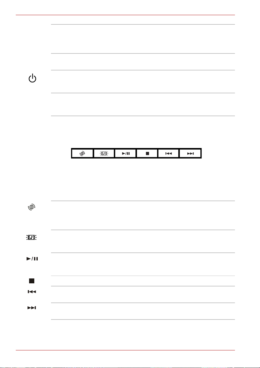
AV Button
Six buttons are provided with some models.
Available for use: Internet, CD/DVD, Play/Pause, Stop, Previous, Next.
These buttons allow you to manage Audio/Video, run applications and
access utilities.
Refer to the AV button function section in Chapter 4, Operating Basics for
details.
Internet Button Press this button to launch an Internet browser. If
the computer’s power is off, you can press this
button to turn on the computer’s power and
launch the browser automatically in one step.
CD/DVD Button Pressing this button will launch an application
program that allows Windows Media Player / DVD
Video Player.
Play/Pause
Button
Press this button to begin playing an audio CD, a
DVD movie or digital audio files. This button also
acts as a Pause button.
STOP Press this button to stop play.
Previous Button Press this button to advance to the previous
track, chapter or data.
Next Button Press this button to advance to the next track,
chapter or data.
2-8 User’s Manual

System indicators
The following figure shows the system indicators, which light when various
computer operations are in progress.
A210 Series
Multiple Digital Media
card slot
Disk
Main battery
DC IN
System indicators
Power
Power source/system indicators
DC IN The DC IN indicator glows blue when DC power is
supplied from the AC power adaptor. If the
adaptor’s output voltage is abnormal or if the
power supply malfunctions, this indicator flashes
amber.
Power The Power indicator glows blue when the
computer is on. If you turn off the computer in
Sleep mode, this indicator blinks amber while the
computer shuts down.
Main Battery The Main battery indicator shows the condition of
the charge. Blue means fully charged and amber
means being charged. Refer to Chapter 6, Power
and Power-Up Modes.
Disk The Disk indicator glows blue when the computer
Multiple Digital
Media Card Slot
is accessing a disk drive.
The Multiple digital Media Card Slot indicator
glows blue when the computer is accessing the
Multiple Digital Media Card Slot.
User’s Manual 2-9

A210 Series
Keyboard indicators
When the CAPS LOCK indicator glows the keyboard is in all-caps mode.
CAPS LOCK This indicator glows green when the alphabet
The figures below show the positions of the keypad overlay indicators and
the CAPS LOCK indicator.
When the F10 key indicator glows the keypad overlay lets you control the
cursor.
When the F11 key indicator glows the keypad overlay lets you enter
numbers.
Numeric mode
Caps Lock Indicator
CAPS LOCK indicator
keys are locked in uppercase.
Arrow mode
Keypad overlay indicators
Arrow mode When the Arrow mode indicator lights green, you
can use the keypad overlay (white labeled keys)
as cursor keys. Refer to the Keypad overlay
section in Chapter 5, The Keyboard.
Numeric mode You can use the keypad overlay (white labeled
keys) for numeric input when the Numeric mode
indicator lights green. Refer to the Keypad
overlay section in Chapter 5, The Keyboard.
2-10 User’s Manual

Optical disc drive
DVD Super Multi (+-R DL). An ATAPI interface controller is used for
CD/DVD-ROM operation. When the computer is accessing a CD/DVD, an
indicator on the drive glows.
■ Unfinalized DVDs created on home DVD recorders may not be
playable on the computer.
■ When inserting an unfinalized DVD-R DL disc into the computer,
Windows Vista
writing.
Region codes for DVD drives and media
Optical disc drive and media are manufactured according to the
specifications of six marketing regions. When you purchase DVD-Video,
make sure it matches your drive, otherwise it will not play properly.
Code Region
1 Canada, United States
2 Japan, Europe, South Africa, Middle East
3 Southeast Asia, East Asia
4 Australia, New Zealand, Pacific Islands, Central America,
®
may automatically finalize the disc and prevent further
South America, Caribbean
A210 Series
5 Russia, Indian Subcontinent, Africa, North Korea, Mongolia
6China
Writable discs
This section describes the types of writable CD/DVD discs.
Check the specifications for your drive to for the type of discs it can write.
Use TOSHIBA Disc Creator to write compact discs. Refer to Chapter 4,
Operating Basics.
CDs
■ CD-R discs can be written only once. The recorded data cannot be
erased or changed.
■ CD-RW discs can be recorded more than once. Use either 1, 2, or
4 multi speed CD-RW discs or high-speed 4 to 10 speed discs. The
write speed of the ultra-speed CD-RW discs (Ultra-speed is CD-RW/
DVD-ROM drive only) is maximum 24 speed.
User’s Manual 2-11

A210 Series
DVDs
■ DVD-R, DVD+R, DVD-R DL and DVD+R DL discs can be written only
once. The recorded data cannot be erased or changed.
■ DVD-RW, DVD+RW and DVD-RAM discs can be recorded more than
once.
Formats
The drives support the following formats:
■ DVD-ROM ■ DVD-Video
■ CD-DA ■ CD-Text
■ Photo CD™ (single/multi-session) ■ CD-ROM Mode 1, Mode 2
■ CD-ROM x A Mode 2 (Form1, Form2) ■ Enhanced CD
■ CD-G (Audio CD only)
DVD Super Multi (+-R DL) drive
The full-size DVD Super Multi drive module lets you record data to s as
rewritable CDs as well as run either 12 cm (4.72") or 8 cm (3.15") CD/DVDs
without using an adaptor
The read speed is slower at the center of a disc and faster at the outer
edge.
.
DVD read 8 speed (maximum)
DVD-R write 8 speed (maximum)
DVD-RW write 6 speed (maximum)
DVD+R write 8 speed (maximum)
DVD+RW write 8 speed (maximum)
DVD+R DL write 4 speed (maximum)
DVD-R DL write 4 speed (maximum)
DVD-RAM write 5 speed (maximum)
CD-R write 24 speed (maximum)
CD-RW write 16 speed (maximum, ultra-speed media)
(CD-EXTRA)
2-12 User’s Manual
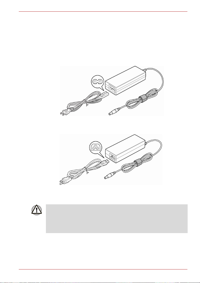
AC adaptor
The AC adaptor converts AC power to DC power and reduces the voltage
supplied to the computer. It can automatically adjust to any voltage from
100 to 240 volts and to a frequency of either 50 or 60 hertz, enabling you to
use the computer in almost any region.
To recharge the battery, simply connect the AC adaptor to a power source
and the computer. See Chapter 6, Power and Power-Up Modes for details.
A210 Series
The AC adaptor(2-pin plug)
The AC adaptor (3-pin plug)
■ Use of the wrong adaptor could damage your computer. TOSHIBA
assumes no liability for any damage in such case. The output rating for
the computer is 19 volts DC.
■ Please use only the AC adaptor supplied with the computer or an AC
adaptor certified by TOSHIBA.
User’s Manual 2-13

A210 Series
2-14 User’s Manual

Getting Started
This chapter provides basic information to get you started using your
computer. It covers the following topics:
Be sure also to read Instruction Manual for Safety & Comfort. This guide,
which is included with the computer, explains product liability.
■ Connecting the AC adaptor
■ Opening the display
■ Turning on the power
■ Starting up for the first time
■ Turning off the power
■ Restarting the computer
■ System Recovery Options
If you are a new user, follow the steps in each section of this chapter as you
prepare to operate your computer.
A210 Series
Chapter 3
All users should be sure to carefully read the sections Windows Vista®
setup, which describe actions to take when you turn on the power for the
first time.
User’s Manual 3-1

A210 Series
Connecting the AC adaptor
Attach the AC adaptor when you need to charge the battery or you want to
operate from AC power. It is also the fastest way to get started, because
the battery pack will need to be charged before you can operate from
battery power.
The AC adaptor can be connected to any power source supplying from 100
to 240 volts and 50 or 60 hertz. For details on using the AC adaptor to
charge the battery pack, refer to Chapter 6, Power and Power-Up Modes.
Use of the wrong adaptor could damage your computer. TOSHIBA
assumes no liability for any damage in such case. The output rating for the
computer is 19 volts DC.
1. Connect the power cord to the AC adaptor.
Connecting the power cord to the AC adaptor
2. Connect the AC adaptor’s DC output plug to the DC IN port on the right
side of the computer.
DC-IN
Connecting the adaptor to the computer
3. Plug the power cord into a live wall outlet. The Battery and DC IN
indicator on the front of the computer should glow.
3-2 User’s Manual

Opening the display
The display panel can be rotated in a wide range of angles for optimal
viewing.
1. Slide the display latch on the front of the computer to the right to unlatch
the display panel.
2. Lift the panel up and adjust it to the best viewing angle for you.
When you open the display, hold it with both hands and lift up slowly.
.
A210 Series
Display latch
Opening the display panel
Turning on the power
This section describes how to turn on the power.
After you turn on the power for the first time, do not turn it off until you have
set up the operating system (OS) and the OS has started up.
1. If the external diskette drive is connected, make sure it is empty. If a
diskette is in the drive, press the eject button and remove the diskette.
2. Open the display panel.
3. Press and hold the computer’s power button for two or three seconds.
Power Button
Turning on the power
User’s Manual 3-3

A210 Series
Starting up for the first time
When you first turn on the power, the computer’s initial screen is the
Microsoft
Follow the on-screen directions.
®
Windows Vista® Startup Screen Logo.
Turning off the power
The power can be turned off in one of the following modes: Shut down
(Boot), Hibernation or Sleep mode.
Shut Down mode (Boot mode)
When you turn off the power in Shut Down mode, no data is saved and the
computer will boot to the operating system’s main screen.
1. If you have entered data, save it to the hard disk or to a diskette.
2. Make sure all disk(disc) activity has stopped, then remove any
CD/DVDs or diskette.
Make sure the Disk’s indicator is off. If you turn off the power while a
disk(disc) is being accessed, you can lose data or damage the disk(disc).
3. Click Windows Start button, point to , and then select Shut Down.
4. Turn off the power to any peripheral devices.
Do not turn the computer or devices back on immediately. Wait a moment
to let all capacitors fully discharge.
Hibernation mode
The hibernation feature saves the contents of memory to the hard disk
when the computer is turned off. The next time the computer is turned on,
the previous state is restored. The hibernation feature does not save the
status of peripheral devices.
■ While entering hibernation mode, the computer saves the contents of
memory to the HDD. Data will be lost if you remove the battery or
disconnect the AC adaptor before the save is completed. Wait for the
Disk indicator to go out.
■ Do not install or remove a memory module while the computer is in
hibernation mode. Data will be lost.
3-4 User’s Manual

Benefits of hibernation
The hibernation feature provides the following benefits:
■ Saves data to the hard disk when the computer automatically shuts
down because of a low battery.
For the computer to shut down in hibernation mode, the hibernation feature
must be enabled in two places: the Hibernate tab in Power Options and
Setup Action tab in TOSHIBA Power Saver. Otherwise, the computer will
shut down in Sleep mode. If battery power becomes depleted, data saved
in Sleep mode will be lost.
■ You can return to your previous working environment immediately when
you turn on the computer.
■ Saves power by shutting down the system when the computer receives
no input or hardware access for the duration set by the System
hibernate feature.
■ You can use the panel power off feature.
Starting Hibernation
To enter Hibernation mode, follow the steps below.
Windows Vista
1. Click Windows Start button.
2. Point to .
3. Select Hibernate.
®
A210 Series
Automatic Hibernation
The computer will enter Hibernate mode automatically when you press the
power button or close the lid. First, however, make the appropriate settings
according to the steps below.
1. Open the Control Panel.
2. Open Mobile PC and open Power Options.
3. Select Choose what the power button does.
4. Enable the desired Hibernation settings for When I press the power
button and When I close the lid.
5. Click the Save changes button.
User’s Manual 3-5

A210 Series
Sleep mode
Data save in hibernation mode
When you turn off the power in hibernation mode, the computer takes a
moment to save current memory data to the hard disk. During this time, the
Built-in HDD indicator will light.
After you turn off the computer and memory is saved to the hard disk, turn
off the power to any peripheral devices.
Do not turn the computer or devices back on immediately. Wait a moment
to let all capacitors fully discharge.
In sleep mode the power remains on, but the CPU and all other devices are
in sleep mode.
■ Before entering Sleep mode, be sure to save your data.
■ Do not install or remove a memory module while the computer is in
sleep mode. The computer or the module could be damaged.
■ Do not remove the battery pack while the computer is in sleep mode
(unless the computer is connected to an AC power source). Data in
memory will be lost.
Benefits of sleep
The sleep feature provides the following benefits:
■ Restores the previous working environment more rapidly than does
hibernation.
■ Saves power by shutting down the system when the computer receives
no input or hardware access for the duration set by the System Sleep
feature.
■ You can use the panel power off feature.
3-6 User’s Manual

A210 Series
Executing sleep
You can also enable Sleep by pressing FN+F3. See Chapter 5, The
Keyboard for details.
You can enter sleep mode in one of three ways:
1. Click Windows Start button, point to , and then click Sleep.
2. Close the display panel. This feature must be enabled. Refer to the
Power Options in the Control Panel.
3. Press the power button. This feature must be enabled. Refer to the
Power Option in the Control Panel.
When you turn the power back on, you can continue where you left when
you shut down the computer.
■ When the computer is shut down in sleep mode, the power indicator
glows amber.
■ If you are operating the computer on battery power, you can lengthen
the operating time by shutting down in hibernation mode. Sleep mode
consumes more power.
Sleep limitations
Sleep will not function under the following conditions:
■ Power is turned back on immediately after shutting down.
■ Memory circuits are exposed to static electricity or electrical noise.
Restarting the computer
Certain conditions require that you restart the computer system. For
example, if:
■ You change certain computer settings.
■ An error occurs and the computer does not respond to your keyboard
commands.
If you need to restart the computer, there are three ways this can be
achieved:
1. Click Start, then click the narrow ( ) in the power management button
( ) and select Restart from the menu.
2. Press CTRL + ALT + DEL to display the menu window, then select
Restart from the Shut down options.
3. Press the power button and hold it down for five seconds. Once the
computer has turned itself off, wait between ten and fifteen seconds
before turning the power on again by pressing the power button.
User’s Manual 3-7

A210 Series
System Recovery Options
About 1.5 GB hidden partition is allocated on the hard disk drive for the
System Recovery Options. This partition stores files which can be used to
repair the system in the event of a problem.
System Recovery Options
The System Recovery Options feature is installed on the hard disk when
shipped from the factory. The System Recovery Options menu includes
some tools to repair startup problems, run diagnostics or restore the
system.
You can see the more information about “Startup Repair” in “Windows Help
and Support” content.
The System Recovery Options can also be run manually to repair
problems.
1. Turn off the computer.
2. While holding the F8 key, turn the computer on again.
3. The Advanced Boot Options menu will be displayed. Use the arrow
keys to select Repair Your Computer and press ENTER.
4. Follow the on-screen instructions from this point onward.
The Window Vista Complete PC Backup feature can be used on Windows
®
Vista
Business Edition and Ultimate Edition.
Restoring the pre-installed software
If preinstalled files are damaged, use the Product Recovery DVD-ROM to
restore them. To restore the operating system and all preinstalled software,
follow the steps below.
When you reinstall the Windows operating system, the hard disk will be
reformatted and all data will be lost.
1. Load the Product Recovery disc in the drive and turn off the
computer’spower.
2. Switch on the computer and, when the In Touch with Tomorrow
TOSHIBA prompt appears, press the F12 key to display the Boot Menu.
3. Use the up or down cursor key to select the CD-ROM/DVD drive in the
display menu.
4. Follow the on-screen instructions.
5. If your computer came with additional software installed, this software
can not be recovered from the Product Recovery DVD-ROM. Re-install
these applications (e.g. Works Suite, Games, etc.) separately from
other media.
3-8 User’s Manual
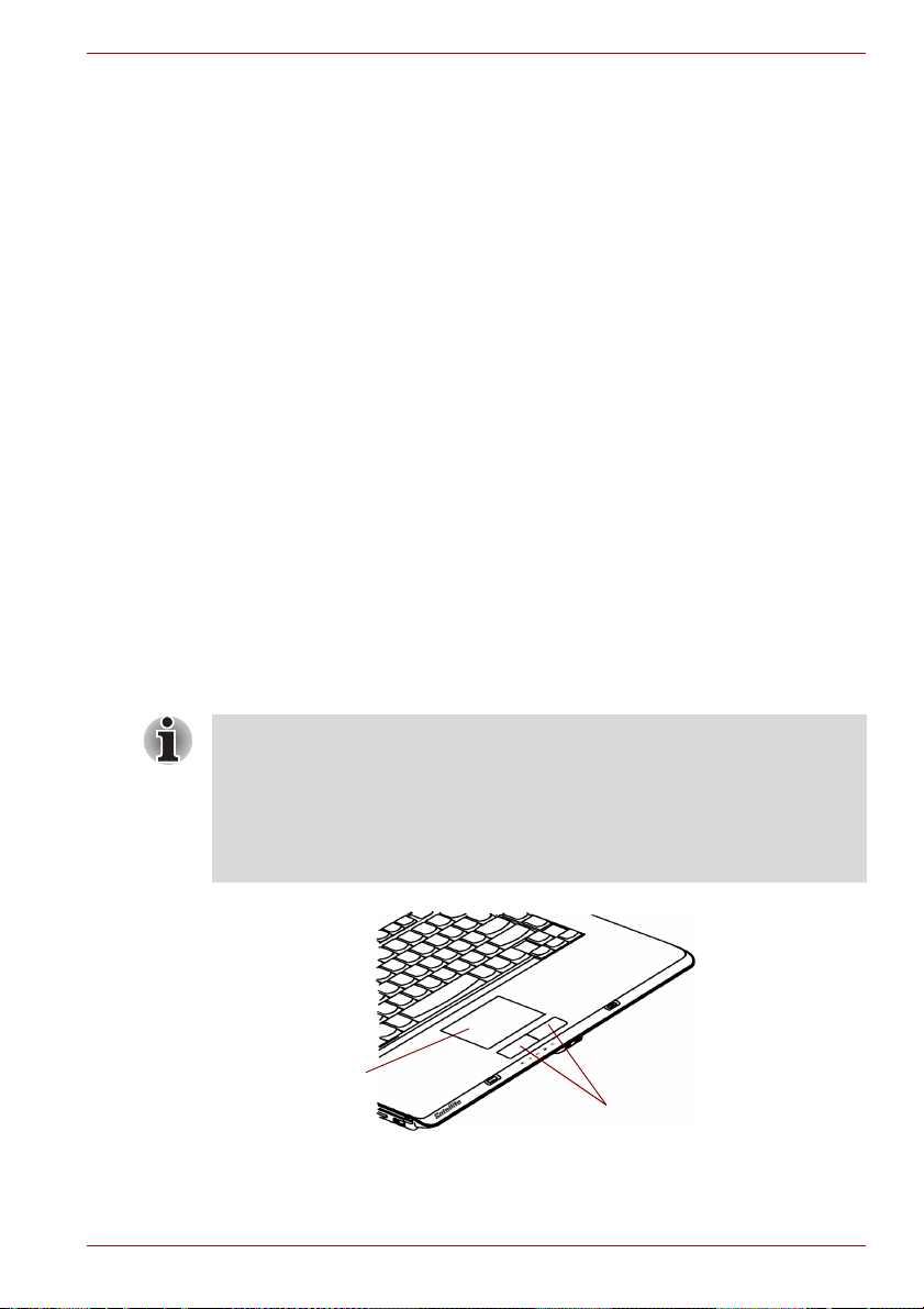
Operating Basics
This chapter gives information on basic operations including using the
Touch Pad, optical disc drives, the web camera, the microphone, the
internal modem, wireless communication and LAN. It also provides tips on
caring for your computer, diskettes and CD/DVDs.
Using the Touch Pad
To use the Touch Pad, simply touch and move your finger tip across it in the
direction you want the on-screen pointer to go.
Two buttons below the Touch Pad are used like the buttons on a mouse
pointer.
Press the left button to select a menu item or to manipulate text or graphics
designated by the pointer. Press the right button to display a menu or other
function depending on the software you are using.
A210 Series
Chapter 4
You can also tap the Touch Pad to Perform functions similar to those of the
left button.
Click: Tap the Touch Pad once.
Double click: Tap t w ice .
Drag and drop: Tap to select the material you want to move. Leave your
finger on the Touch Pad after the second tap and move the material.
Touch Pad
Touch Pad Control Buttons
Touch Pad and Touch Pad control buttons
User’s Manual 4-1

A210 Series
Using optical disc drives
The text and illustrations in this section refer primarily to the optical disc
drive. However, operation is the same for all other optical disc drives. The
full-size drive provides high-performance execution of CD/DVD ROMbased programs. You can run either 12 cm (4.72") or 8 cm (3.15") CD/DVD
without an adaptor. An ATAPI interface controller is used for CD/DVD-ROM
operation. When the computer is accessing a CD/DVD-ROM, an indicator
on the drive glows.
Use the TOSHIBA DVD Video Player application to view DVD-Video
discs.(CD-RW/DVD-ROM drive model or DVD Super Multi drive model)
If you have a DVD Super Multi drive or a HD DVD-ROM drive, refer to the
Writing CD/DVDs on DVD Super Multi drive section for precautions on
writing to CDs/DVDs.
Loading discs
To load CD/DVDs, follow the steps below and refer to the following figures.
1. a. When the power is on, press the eject button to open the drawer
slightly.
Eject button
Pressing the eject button
4-2 User’s Manual

A210 Series
b. Pressing the eject button will not open the drawer when the drive’s
power is off. If the power is off, you can open the drawer by inserting
a slender object (about 15 mm) such as a straightened paper clip
into the eject hole just to the right of the eject button.
Eject Hole
Manual release with the eject hole
2. Grasp the drawer gently and pull until it is fully opened.
Pulling the drawer open
User’s Manual 4-3

A210 Series
3. Lay the CD/DVD, label side up, in the drawer.
Inserting a CD/DVD
When the drawer is fully opened, the edge of the computer will extend
slightly over the CD/DVD tray. Therefore, you will need to turn the CD/DVD
at an angle when you place it in the tray. After seating the CD/DVD,
however, make sure it lies flat, as shown in above figures.
■ Do not touch the laser lens. Doing so could cause misalignment.
■ Do not keep foreign matter from entering the drive. Check the back
edge of the tray to make sure it carries no debris before closing the
drive.
4. Press gently at the center of the CD/DVD until you feel it click into
place. The CD/DVD should lie below the top of the spindle, flush with
the spindle base.
5. Push the center of the drawer to close it. Press gently until it locks into
place.
If the CD/DVD is not seated properly when the drawer is closed, the
CD/DVD might be damaged. Also, the drawer might not open fully when
you press the eject button.
Closing the drawer
4-4 User’s Manual

Removing discs
To remove the CD/DVD, follow the steps below and refer to
the following figures.
Do not press the eject button while the computer is accessing the drive.
Wait for the optical disc drive indicator to go out before you open the
drawer. Also, if the CD/DVD is spinning when you open the drawer, wait for
it to stop before you remove it.
1. To pop the drawer partially open, press the eject button. Gently pull the
drawer out until it is fully opened.
■ When the drawer pops open slightly, wait a moment to make sure the
CD/DVD has stopped spinning before pulling the drawer fully open.
■ Turn off the power before you use the eject hole. If the CD/DVD is
spinning when you open the drawer, the CD/DVD could fly off the
spindle and cause injury.
2. The CD/DVD extends slightly over the sides of the drawer so you can
grasp it. Hold the CD/DVD gently and lift it out.
A210 Series
Removing a CD-RW/DVD
3. Push the center of the drawer to close it. Press gently until it locks into
place.
User’s Manual 4-5

A210 Series
AV Button function
This section describes a button function.
Six button are provided with some models.
AV Button
Icon AV Button DVD *CD/None
CD/DVD Launch DVD Video Player Launch Windows Media
Play/Pause Play/Pause Play/Pause
Stop Stop Stop
Previous Previous chapter Previous tune
Next Next chapter Next tune
*Windows Media Player 11
Player
Writing CD/DVDs on DVD Super Multi (+-R DL) drive
You can use the DVD Super Multi (+-R DL ) drive to write data to either
CD-R/RW or DVD-R/-RW/+R/+RW/-RAM/+R DL/-R DL discs. The following
applications for writing are supplied: TOSHIBA Disc Creator. Ulead DVD
MovieFactory® for TOSHIBA, which is a product of Ulead Systems, Inc.
Important message (DVD Super Multi (+-R DL) drive)
Before you write or rewrite to CD-R/RW or DVD-R/-RW/+R/+RW/-RAM/+R
DL/-R DL disc, read and follow all setup and operating instructions in this
section.
If you fail to do so, the DVD Super Multi (+-R DL) drive may not function
properly, and you may fail to write or rewrite, lose data or incur other
damage.
4-6 User’s Manual

Before writing or rewriting
■ Based on TOSHIBA’s limited compatibility testing, we suggest the
following manufacturers of CD-R/RW and DVD-R/+R/-RW/+RW/-RAM/
+R DL/-R DL disc.
■ However, in no event does TOSHIBA guarantee the operation, quality
or performance of any disc. Disc quality can affect write or rewrite
success rates.
CD-R: TAIYO YUDEN CO., LTD.
CD-RW:
(High-Speed,
MultiSpeed)
CD-RW:
(Ultra-Speed)
DVD-R DVD Specifications for Recordable Disc for
DVD+R MITSUBISHI KAGAKU MEDIA CO., LTD
DVD-RW DVD Specifications for Recordable Disc for
DVD+RW MITSUBISHI KAGAKU MEDIA CO., LTD
DVD-RAM DVD Specifications for DVD-RAM Disc for
DVD+R DL MITSUBISHI KAGAKU MEDIA CO., LTD.
DVD-R DL MITSUBISHI KAGAKU MEDIA CO., LTD.
DVD-R for
Labelflash™
DVD+R for
Labelflash™
MITSUBISHI KAGAKU MEDIA CO., LTD
Ricoh Co., Ltd.
Hitachi Maxell Ltd.
MITSUBISHI KAGAKU MEDIA CO., LTD
Ricoh Co., Ltd.
MITSUBISHI KAGAKU MEDIA CO., LTD
General
Version 2.0
TAIYO YUDEN CO., LTD.
Matsushita Electric Industrial Co., Ltd.
Ricoh Co., Ltd.
Version 1.1
VICTOR COMPANY OF JAPAN, LIMITED
MITSUBISHI KAGAKU MEDIA CO., LTD
Ricoh Co., Ltd.
Version 2.0, Version 2.1 or Version 2.2
Matsushita Electric Industrial Co., Ltd.
Hitachi Maxell Ltd.
FUJIFILM Corporation.
FUJIFILM Corporation.
A210 Series
User’s Manual 4-7

A210 Series
This drive cannot use discs that allow writing of 8 speeds or more (DVD-R,
DVD+R ), 6 speeds or more (DVD-RW) and 8 speeds or more (DVD+RW).
■ If the disc is poor in quality, dirty or damaged, writing or rewriting errors
may occur. Be careful to check the disc for dirt or damage before you
use it.
■ The actual number of rewrites to CD-RW, DVD-RW, DVD+RW or
DVD-RAM is affected by the quality of the disc and the way it is used.
■ There are two types of DVD-R discs: authoring and general use discs.
Do not use authoring discs. Only general use discs can be written to by
a computer drive.
■ We can support only format 1 of DVD-R DL. Therefore you can not do
the additional writing. If your data is under DVD-R(SL) capacity, we
suggest to use DVD-R(SL) media.
■ You can use DVD-RAM discs that can be removed from a cartridge and
DVD-RAM discs designed without a cartridge. You cannot use a disc
with a 2.6 GB single-sided capacity or 5.2 GB double-sided capacity.
■ Other DVD-ROM drives for computers or other DVD players may not be
able to read DVD-R/-R DL/-RW or DVD+R/+R DL/+RW discs.
■ Data written to a CD-R/DVD-R/DVD+R disc cannot be deleted either in
whole or in part.
■ Data deleted (erased) from a CD-RW and DVD-RW, DVD+RW and
DVD-RAM disc cannot be recovered. Check the content of the disc
carefully before you delete it. If multiple drives that can write data to
discs are connected, be careful not to delete data from the wrong drive.
■ In writing to a DVD-R/-R DL/-RW, DVD+R/+R DL/+RW or DVD-RAM
disc, some disc space is required for file management, so you may not
be able to write the full capacity of the disc.
■ Since the disc is based on the DVD standard, it will be filled with dummy
data if the written data is less than about 1 GB. Even if you write only a
small amount of data, it might take time to fill in the dummy data.
■ DVD-RAM formatted by FAT32 cannot be read in Windows 2000
without DVD-RAM Driver Software.
■ When multiple drives that can write data to discs are connected, be
careful not to write to the wrong drive.
■ Be sure to connect the universal AC adaptor before you write or rewrite.
■ Before you enter sleep/hibernation mode, be sure to finish DVD-RAM
writing. Writing is finished if you can eject DVD-RAM media.
■ Be sure to close all other software programs except the writing
software.
■ Do not run software such as a screen saver, which can put a heavy load
on the CPU.
■ Operate the computer in the full-power mode. Do not use power-saving
features.
4-8 User’s Manual

■ Do not write while virus check software is running. Wait for it to finish,
and then disable virus detection programs including any software that
checks files automatically in the background.
■ Do not use hard disk utilities, including those intended to enhance HDD
access speed. They may cause unstable operation and data damage.
■ Write from the computer’s HDD to the CD/DVD. Do not try to write from
shared devices such as a LAN server or any other network device.
■ Writing with software other than TOSHIBA Disc Creator is not
recommended.
When writing or rewriting
Please observe/consider the following when you write or rewrite to a
CD-R/RW, DVD-R/-R DL/-RW/-RAM or DVD+R/+R DL/+RW disc.
■ Do not perform any of the following actions:
■ Change users in the Windows Vista
■ Operate the computer for any other function, including use of a
mouse or Touch Pad, closing/opening the LCD panel.
■ Start a communication application such as a modem.
■ Apply impact or vibration to the PC.
■ Install, remove or connect external devices, including the following:
Express Card, USB devices, external display, i.LINK devices, optical
digital devices.
■ Use the Audio/Video control button to reproduce music or voice.
■ Open the CD-RW/DVD-ROM or DVD Super Multi (+-R DL) drive.
■ Do not use shut down/log off and sleep/hibernation while writing or
rewriting.
■ Make sure writing or rewriting is completed before going into
sleep/hibernation. Writing is completed if you can open the
CD-RW/DVD-ROM or DVD Super Multi (+-R DL) drive tray.
■ Set the computer on a level surface and avoid places subject to
vibration such as airplanes, trains, or cars. Do not use an unstable
surface such as a stand.
■ Keep mobile phones and other wireless communication devices away
from the computer.
■ Always copy data from the HDD to the DVD-RAM. Do not use
cut-and-paste. The original data will be lost if there is a write error.
®
operating system.
A210 Series
User’s Manual 4-9

A210 Series
Disclaimer (DVD Super Multi (+-R DL) drive)
TOSHIBA does not bear responsibility for the following:
■ Damage to any CD-R/RW or DVD-R/-R DL/-RW/+R/+R DL/+RW/
DVD-RAM disc that may be caused by writing or rewriting with this
product.
■ Any change or loss of the recorded contents of CD-R/RW or
DVD-R/-R DL/-RW/+R/+R DL/+RW/DVD-RAM disc that may be caused
by writing or rewriting with this product, or for any business profit loss or
business interruption that may be caused by the change or loss of the
recorded contents.
■ Damage that may be caused by using third party equipment or
software. Given the technological limitations of current optical disc
writing drives, you may experience unexpected writing or rewriting
errors due to disc quality or problems with hardware devices. Also, it is
a good idea to make two or more copies of important data, in case of
undesired change or loss of the recorded contents.
TOSHIBA Disc Creator
Note the following limitations when you use TOSHIBA Disc Creator:
■ DVD-Video cannot be created using TOSHIBA Disc Creator.
■ DVD-Audio cannot be created using TOSHIBA Disc Creator.
■ You cannot use TOSHIBA Disc Creator’s “Audio CD for Car or Home
CD Player” function to record music to DVD-R, DVD-R (Dual Layer),
DVD-RW, DVD+R, DVD+R (Double Layer), DVD+RW.
■ Do not use the “Disc Backup” function of TOSHIBA Disc Creator in
order to copy DVD Video, DVD-ROM material that has copyright
protection.
■ DVD-RAM discs cannot be backed up using the “Disc Backup”
functionof TOSHIBA Disc Creator.
■ You cannot back up CD-ROM, CD-R or CD-RW media to DVD-R,
DVD-R (Dual Layer), DVD-RW media using the “Disc Backup” function
of TOSHIBA Disc Creator.
■ You cannot back up CD-ROM, CD-R or CD-RW media to DVD+R,
DVD+R (Double Layer) or DVD+RW media using the “Disc Backup”
function of TOSHIBA Disc Creator.
■ You cannot back up DVD-ROM, DVD Video, DVD-R, DVD-R (Dual
Layer), DVD-RW, DVD+R, DVD+R (Double Layer), DVD+RW to CD-R
or CD-RW media using the “Disc Backup” function of TOSHIBA Disc
Creator.
■ TOSHIBA Disc Creator cannot record in packet format.
4-10 User’s Manual

A210 Series
■ You might not be able to use the “Disc Backup” function of TOSHIBA
Disc Creator to back up a DVD-R, DVD-R (Dual Layer), DVD-RW,
DVD+R, DVD+R (Double Layer), DVD+RW disc that was made with
other software on a different optical media recorder.
■ If you add data to a DVD-R, DVD-R (Dual Layer), DVD+R, DVD+R
(Double Layer) disc that you have already recorded to, you might not be
able to read the added data under some circumstances. For example, it
cannot be read under 16-bit operating systems, such as Windows 98SE
and Windows Me, while in Windows NT4 you will need Service Pack 6
or later, and in Windows 2000, you will need Service Pack 2. In addition
to this, some DVD-ROM and DVD-ROM / CD-R/RW drives cannot read
this added data regardless of the operating system.
■ TOSHIBA Disc Creator does not support recording to DVD-RAM discs -
to achieve this you should use Windows Explorer or another similar
utility.
■ When you back up a DVD disc, be sure that the source drive supports
recording to DVD-R, DVD-R (Dual Layer), DVD-RW, DVD+R, DVD+R
(Double Layer) or DVD+RW media - if this is not the case then the
source disc might not be backed up correctly.
■ When you back up a DVD-R, DVD-R (Dual Layer), DVD-RW, DVD+R,
DVD+R (Double Layer) or DVD+RW disc, be sure to use the same type
of disc.
■ You cannot partially delete any data written to a CD-RW, DVD-RW,
DVD+RW disc.
Data Verification
To verify that data has been written or rewritten correctly to a data
CD/DVD you should follow the steps below before you begin the write/
rewrite process:
1. Display the setting dialog box by one of the following two steps:
■ Click the Recording settings button( ) for writing on the main
toolbar in the Data Disc mode.
■ Select Setting for Each Mode -> Data Disc in the Setting menu.
2. Mark the Verify written data check box.
3. Select File Open or Full Compare mode.
4. Click the OK button.
How to learn more about TOSHIBA Disc Creator
Please refer to the Help files for additional TOSHIBA Disc Creator
information.
Video
You can record video using Ulead DVD MovieFactory® for TOSHIBA.
User’s Manual 4-11

A210 Series
When using Ulead DVD MovieFactory® for TOSHIBA:
Set PRINTING SIDE for underside.
How to make a DVD-Video
Simplified steps for making a DVD-Video from video data captured from a
DV-Camcorder:
1. Click Start -> All Programs -> DVD MovieFactory for TOSHIBA ->
Ulead DVD MovieFactory for TOSHIBA Launcher to launch DVD
MovieFactory.
2. Insert a DVD-RW or DVD+RW disc in Burner.
3. Click Video Disc -> Burn Video to Disc to launch Direct Recording
dialog box, choose DVD-Video/+VR to invoke Straight Capture to
Disc Page.
4. Choose DVD-Video format.
5. Confirm the capture source is DV.
6. Press Capture button.
Simplified steps for making a DVD-Video from adding video source:
1. Click Start -> All Programs -> DVD MovieFactory for TOSHIBA ->
Ulead DVD MovieFactory for TOSHIBA Launcher to launch DVD
MovieFactory.
2. Click Video Disc -> New Project to invoke 2
project type, then invoke DVD MovieFactory.
3. Add source from HD Disk by click Add Video files button to invoke
browser dialog box.
4. Choose the source video then go to Next page to apply Menu
5. After choose the menu template, press Next button to go to Burning
Page.
6. choose the output type then press Burn button.
nd
Launcher, choose your
How to learn more about Ulead DVD MovieFactory
Please refer to the on-line Help and Manual files for additional Ulead
MovieFactory information.
4-12 User’s Manual

A210 Series
Important information for use
Note the following limitations when you write video DVD:
1. Editing digital video.
■ Log in with Administrator rights to use DVD MovieFactory.
■ Make sure that your computer is running on AC power when using
DVD MovieFactory.
■ Operate the computer at Full Power. Do not use power-saving
features.
■ While you are editing DVD, you can display previews. However, if
another application is running, the preview might not display properly.
■ DVD MovieFactory cannot edit or play copy protected content.
■ Do not enter sleep or hibernation mode while using DVD
MovieFactory.
■ Do not operate DVD MovieFactory immediately after turning on the
computer. Please wait until all Disc Drive activity has stopped.
■ When recording to a DV-Camcorder, to ensure you capture all of
your data, let the camcorder record for a few seconds before you
begin recording your actual data.
■ CD recorder, JPEG functions, DVD-Audio, mini DVD, and Video CD
functions are not supported in this version.
■ While recording video to DVD, please close all other programs.
■ Do not run software like a screen saver because it can put a heavy
load on the CPU.
■ Do not support mp3 decode and encode.
2. Before recording the video to DVD.
■ When you record to DVD disc, please use only discs recommended
by the Drive manufacturer.
■ Do not set the working drive to a slow device like a USB 1.1 hard
disk drive or it will fail to write DVD.
■ Do not perform any of the following actions:
■ Operate the computer for any other function, including using a
mouse or TouchPad or closing/opening the LCD panel.
■ Bump or cause vibration to the computer.
■ Use the Mode control button and Audio/Video control button to
reproduce music or voice.
■ Open the DVD drive.
■ Install, remove or connect external devices, including the
following: Express Card, SD card, USB device, external display,
i.LINK devices, optical digital devices.
■ Please verify your disc after recording important data.
■ DVD-R/+R/-RW disc cannot be written in VR format.
■ Not support to output VCD and SVCD format.
User’s Manual 4-13

A210 Series
3. About Straight to Disc
4. About recorded DVDs
Media care
This section provides tips on protecting data stored on your CD/DVD.
Handle your media with care. The following simple precautions will
increase the lifetime of your media and protect the data stored on them:
CD/DVD
1. Store your CD/DVD in the container they came in to protect them and
2. Do not bend the CD/DVD.
3. Do not write on, apply a sticker to, or otherwise mark the surface of the
4. Hold the CD/DVD by its outside edge or the edge on the center hole.
5. Do not expose to direct sunlight, extreme heat or cold. Do not place
6. If your CD/DVD become dusty or dirty, wipe them with a clean dry cloth.
■ Not support to record on DVD-R/+R disc.
■ Not support to record DVD+VR format by HDV.
■ HDV support to burn DVD-Video only.
■ DVD-VR format not support to add Menu.
■ Some DVD-ROM drives for personal computers or other DVD
players may not be able to read DVD-R/+R/-RW/-RAM discs.
■ When playing your recorded disc on your computer, please use the
DVD Video Player software application.
■ If you use an over-used rewritable disc, the full formatting might be
locked. Please use a brand new disc.
keep them clean.
CD/DVD that contains data.
Fingerprints on the surface can prevent the drive from properly reading
data.
heavy objects on your CD/DVD.
Wipe from the center out, do not wipe in a circular direction around the
CD/DVD. If necessary, use a cloth dampened in water or a neutral
cleaner. Do not use benzine, thinner or similar cleaner.
4-14 User’s Manual

Using the Web Camera
(Built-in Web Camera is provided with some models.)
This section describes the bundled webcam utility, which can capture still
and video images. The web camera will auto-run when Windows starts.
A210 Series
1. Active LED
2. Web Camera Lens
Web Camera
User’s Manual 4-15

A210 Series
Using the software
The web camera software is pre-configured to start when you turn on
Windows Vista; if you need to restart it go to Start -> Programs -> Camera
Assistant Software -> Camera Assistant Software
1. Capture still images 2. Video Recording
3. Video Recording 4. Function
5. Display Window 6. Camera Resolution
7. Mute 8. Effects
Using the Software
Capture Still
Image
Click to see a preview of the captured image; you
can also e-mail the image.
Video Recording Click to prepare for recording. Click again to start
recording. One more to stop recording and see
preview of the video.
Audio Recording Click to start recording, Click again to stop and
listen to a preview of the audio.
Function Access additional functions: About, Player,
Effects, Properties, Settings and Help.
About Display software manufacturer details.
Player Play video files.
Effects Choose images to be displayed on the capture
screen.
Properties Choose from the Options tab to flip, zoom, flicker
rate, night mode and backlight compensation; in
the Image tab change the colour settings; in the
profile tab change the lighting conditions.
4-16 User’s Manual

Settings Choose from the: Options tab to change the tool
Help Displays the help files for the software.
Using the microphone
Your computer has a built-in microphone that can be used to record
monaural sounds into your applications. It can also be used to issue voice
commands to applications that support such functions.(Built-in microphone
is provided with some models)
Since your computer has a built-in microphone and speaker, “feedback”
may be heard under certain conditions. Feedback occurs when sound from
the speaker is picked up in the microphone and amplified back to the
speaker, which amplifies it again to the microphone.
This feedback occurs repeatedly and causes a very loud, high-pitched
noise. It is a common phenomenon that occurs in any sound system when
the microphone input is output to the speaker (throughput) and the speaker
volume is too loud or too close to the microphone. You can control
throughput by adjusting the volume of your speaker or through the Mute
function in the Master Volume panel. Refer to your Windows documentation
for details on using the Master Volume panel.
A210 Series
position; the Picture tab to select picture output
options such as size, export file and saving
location; the Video tab to choose output settings
such as Frama Rate, Size, Compression and the
file save path; the Audio Device, Compression,
Volume and file save path.
Modem
The availability of this feature is depending on the model you purchased.
This section describes how to connect and disconnect the internal modem
to and from a telephone jack.
The internal modem does not support voice functions. All data and fax
functions are supported.
■ In case of a lightning storm, unplug the modem cable from the
telephone jack.
■ Do not connect the modem to a digital telephone line. A digital line will
damage the modem.
User’s Manual 4-17

A210 Series
Region selection
Telecommunication regulations vary from one region to another, so you will
need to make sure the internal modem’s settings are correct for the region
in which it will be used.
To select a region, follow the steps below.
1. In Windows Vista
®
, click start, point to All Programs, point to
TOSHIBA, point to Networking and click Modem Region Select
Utility.
Do not use the Country/Region Select function in the Modem setup utility
in the Control Panel if the function is available. If you change the
Country/Region in the Control Panel, the change may not take effect.
2. The Region Selection icon will appear in the Windows Task Bar.
The Region Selection icon (Windows Vista®)
3. Click the icon with the primary mouse button to display a list of regions
that the modem supports. A sub menu for telephony location
information will also be displayed. A check will appear next to the
currently selected region and telephony location.
4. Select a region from the region menu or a telephony location from the
submenu.
■ When you click a region it becomes the modem’s region selection,
and the New Location for telephony will be set automatically.
■ When you select a telephony location, the corresponding region is
automatically selected and it becomes the modem’s current region
setting.
Properties menu
Click the icon with the secondary mouse button to display the following
menu.
The menu list (Windows Vista®)
4-18 User’s Manual

A210 Series
Setting
You can enable or disable the following settings:
AutoRun Mode
The Region Select utility starts automatically when you start up the
operating system.
Open the Dialing Properties dialog box after selecting region.
The dialing properties dialog box will be displayed automatically after
you select the region.
Location list for region selection.
A submenu appears displaying location information for telephony.
Open dialog box, if the modem and Telephony Current
Location region code do not match.
A warning dialog box is displayed if current settings for region code and
telephony location are incorrect.
Modem Selection
If the computer cannot recognize the internal modem, a dialog box is
displayed. Select the COM port for your modem to use.
Dialing Properties
Select this item to display the dialing properties.
If you are using the computer in Japan, the Telecommunications Business
Law requires that you select Japan region mode. It is illegal to use the
modem in Japan with any other selection.
Connecting
To connect the internal modem cable, follow the steps below.
1. Plug one end of the modular cable into the modem jack.
2. Plug the other end of the modular cable into a telephone jack.
Telephone Jack
Modem Jack
Connecting the internal modem
Do not pull on the cable or move the computer while the cable is
connected.
User’s Manual 4-19

A210 Series
Disconnecting
To disconnect the internal modem cable, follow the steps below.
1. Pinch the lever on the connector in the telephone jack and pull out the
connector.
2. Disconnect the cable from the computer in the same manner.
Wireless communications
The computer’s wireless communication function supports both Wireless
LAN and Bluetooth devices.
Wireless LAN
The Wireless LAN is compatible with other LAN systems based on Direct
Sequence Spread Spectrum/Orthogonal Frequency Division Multiplexing
radio technology that complies with IEEE802.11 wireless LAN standard
(Revision A, B, G or Draft N).
Supported features. It supports the following features:
■ Automatic Transmit Rate Select mechanism in the transmit range of 54,
48, 36, 24, 18, 9 and 6 Mbit/s (Revision A and G).
■ Automatic Transmit Rate Select mechanism in the transmit range of 11,
5.5, 2 and 1 Mbit/s (Revision B).
■ Frequency Channel Selection (Revision A/Draft N: 5 GHz,
Revision B/G/Draft N: 2.4GHz)
■ Roaming over multiple channels
■ Card Power Management
■ Wired Equivalent Privacy (WEP) data encryption, based on the 128 bit
encryption algorithm (Atheros module type).
■ 11a, 11b, 11g and 11n wireless are based on IEEE 802.11a, 802.11b,
802.11g and 802.11n respectively. The IEEE 802.11n specification has
not been finalized and is currently in draft release. The TOSHIBA 11a/b/
g/n Wireless LAN Adapters are based on the Draft Release, Version
1.0, of the IEEE 802.11n specification. An adapter with 11a/b, 11a/b/g or
11a/b/g/n can communicate on any of its supported formats; the actual
connection will be based on the access point to which it connects.
■ Connection compatibility with the wireless equipment in Draft 11n mode
is not guaranteed.
■ The Draft 11n function cannot be used with WEP/TKIP. Draft 11n mode
can be used only with WPA-PSK(AES) mode or no security mode.
4-20 User’s Manual

A210 Series
Security
■ Be sure to enable encryption function. Otherwise your computer will
allow the illegal access by outsider through wireless LAN to cause
illegal instruction, eavesdropping, and loss or destruction of stored data.
TOSHIBA strongly recommends the customer to enable the encryption
function.
■ TOSHIBA is not liable for the eavesdropping of data due to the use of
Wireless LAN and the damage thereof.
Bluetooth® wireless technology
Bluetooth® wireless technology eliminates the need for cables between
electronic devices such as desktop computers, printers and mobile phones.
You cannot use the built-in Bluetooth functions and an optional Bluetooth
Adapter simultaneously.
Bluetooth® wireless technology has the following features:
Worldwide operation
The Bluetooth radio transmitter and receiver operates in the 2.45 GHz band,
which is license-free and compatible with radio systems in most countries in
the world.
Radio links
You can easily establish links between two or more devices. The link is
maintained even if the devices are not within line of sight.
Security
Two advanced security mechanisms ensure a high level of security:
■ Authentication prevents access to critical data and makes it impossible
to falsify the origin of a message.
■ Encryption prevents eavesdropping and maintains link privacy.
Wireless communication switch
You can enable or disable Wireless LAN and Bluetooth functions, with the
on/off switch. No transmissions are sent or received when the switch is off.
Slide the switch toward the left of the computer to turn it on and toward the
right of the computer to turn it off.
Set the switch to off in airplanes and hospitals. Check the indicator. It will
stop glowing when the wireless communication function is off.
Turn the computer off when you enter an airplane and check the carrier’s
regulations before you use a computer on board.
User’s Manual 4-21

A210 Series
Wireless communication Indicator
The wireless communication indicator indicates the status of the wireless
communication functions.
Indicator status Indication
Indicator off Wireless communication switch is set to off.
Automatic power down because of overheating.
Power malfunction
Indicator glows Wireless communication switch is on.
Wireless LAN or Bluetooth is turned on by an
application.
If you used the Task Bar to disable Wireless LAN, restart the computer or
follow the procedures below to enable the system to recognize Wireless
LAN. Click Start, open Control Panel, click System and Maintenance, click
System, click Device Manager, double-click Network Adapters, and
rightclick the wireless device then choose Enable.
It may not be possible to make a network connection to a specified network
name
using the ad hoc network function.
If this occurs, the new network(*) will have to be configured for all
computers connected to the same network in order to re-enable network
connections.
* Please be sure to use new network name.
LAN
The computer has built-in support for Ethernet LAN (10 megabits per
second, 10BASE-T) or Fast Ethernet LAN (100 megabits per second,
100BASE-TX)(depending on model you purchased). This section describes
how to connect/disconnect to a LAN.
Do not install or remove an optional memory module while Wake-up on
LAN is enabled.
The Wake-up on LAN function consumes power even when the system is
off. Leave the AC adaptor connected while using this feature.
4-22 User’s Manual

Connecting LAN cable
The computer must be configured properly before connecting to a LAN.
Logging onto a LAN using the computer’s default settings could cause a
malfunction in LAN operation. Check with your LAN administrator
regarding set-up procedures.
If you are using Fast Ethernet LAN (100 Mbit/s, 100BASE-TX), be sure to
connect with a category 5 cable, CAT5, or higher.
If you are using Ethernet LAN (10 Mbit/s, 10BASE-T), connect with a
category 3 cable, CAT3, or higher.
To connect the LAN cable, follow the steps below.
1. Turn off the power to the computer and to all external devices
connected to the computer.
2. Plug one end of the cable into the LAN jack. Press gently until you hear
the latch click into place.
A210 Series
LAN Jack
Connecting the LAN cable
3. Plug the other end of the cable into a LAN hub connector. Check with
your LAN administrator before connecting to a hub.
When the computer is exchanging data with the LAN, the LAN active
indicator glows amber. When the computer is connected to a LAN hub but
is not exchanging data, the Link indicator glows green.
Disconnecting LAN cable
To disconnect the LAN cable, follow the steps below.
Make sure the LAN active indicator (amber LED) is out before you
disconnect the computer from the LAN.
1. Pinch the lever on the connector in the computer’s LAN jack and pull
out the connector.
2. Disconnect the cable from the LAN hub in the same manner. Check
with your LAN administrator before disconnecting from the hub.
User’s Manual 4-23

A210 Series
Cleaning the computer
To help ensure long, trouble-free operation, keep the computer free of dust
and use care with liquids around the computer.
■ Be careful not to spill liquids into the computer. If the computer does get
wet, turn the power off immediately and let the computer dry completely
before you turn it on again.
■ Clean the computer using a slightly damp (with water) cloth. You can
use glass cleaner on the display. Spray a small amount of cleaner on a
soft, clean cloth and wipe the screen gently with the cloth
Never spray cleaner directly onto the computer or let liquid run into any
part of it. Never use harsh or caustic chemical products to clean the
computer.
.
Moving the computer
The computer is designed for rugged durability. However, a few simple
precautions taken when moving the computer will help ensure trouble-free
operation.
■ Make sure all disk activity has ended before moving the computer.
Check the Disk indicator on the computer.
■ If a CD/DVD is in the drive, remove it. Also make sure the drawer is
securely closed.
■ Turn off the power to the computer.
■ Disconnect the AC adaptor and all peripherals before moving the
computer.
■ Close the display. Do not pick up the computer by its display panel.
■ Close all port covers.
■ Use the carrying case when transporting the computer.
■ When carrying your computer, be sure to hold it securely so that it does
not fall or hit anything.
■ Do not carry your computer by holding protruded portions.
4-24 User’s Manual

Heat dispersal
To protect from overheating, the CPU has an internal temperature sensor. If
the computer’s internal temperature rises to a certain level, the cooling fan
is turned on or the processing speed is lowered. You can select whether to
control the CPU temperature by turning on the fan first, then if necessary,
lowering the CPU speed. Or, by lowering the CPU speed first, then if
necessary, turning on the fan. Use the Cooling Method item of the Basic
Setup window in TOSHIBA Power Saver.
When the CPU temperature falls to a normal range, the fan is turned off
and the CPU operation returns to standard speed.
If the CPU temperature reaches an unacceptably high level with either
setting, the system automatically shuts down to prevent damage. Data in
memory will be lost.
A210 Series
User’s Manual 4-25

A210 Series
4-26 User’s Manual

The Keyboard
The computer’s keyboard layouts are compatible with a 104/105-key
enhanced keyboard. By pressing some keys in combination, all the
104/105-key keyboard functions can be executed on the computer.
The number of keys on your keyboard depends on which country/region’s
keyboard layout your computer is configured with. Keyboards for numerous
languages are available.
There are five types of keys: typewriter keys, keypad overlay, function keys,
soft keys and cursor control keys.
Typewriter keys
The typewriter keys, produce the upper- and lowercase letters, numbers,
punctuation marks, and special symbols that appear on the screen.
There are some differences, however, between using a typewriter and
using a computer keyboard:
■ Letters and numbers produced in computer text vary in width. Spaces,
which are created by a “space character,” may also vary depending on
line justification and other factors.
■ The lowercase l (el) and the number 1 (one) are not interchangeable on
computers as they are on a typewriter.
■ The uppercase O (oh) and the 0 (zero) are not interchangeable.
■ The CAPS LOCK function key locks only the alphabetic characters in
uppercase while the shift lock on a typewriter places all keys in the
shifted position.
■ The SHIFT keys, the TAB key, and the BACK SPACE key perform the
same function as their typewriter counterparts but also have special
computer functions.
A210 Series
Chapter 5
User’s Manual 5-1

A210 Series
F1 ... F12 function keys
The function keys, not to be confused with FN, are the 12 keys at the top of
your keyboard. These keys are dark gray, but function differently from the
other dark gray keys.
F1 through F12 are called function keys because they execute
programmed functions when pressed. Used in combination with the FN
key, keys marked with icons execute specific functions on the computer.
See the section, Soft keys: FN key combinations, in this chapter. The
function executed by individual keys depends on the software you are
using.
Soft keys: FN key combinations
The FN (function) is unique to Toshiba computers and is used in
combination with other keys to form soft keys. Soft keys are key
combinations that enable, disable or configure specific features.
Some software may disable or interfere with soft-key operations.
Soft-key settings are not restored by the Resume feature.
Emulating keys on enhanced keyboard
The keyboard is designed to provide all the features of the 104/105-key
enhanced keyboard. The 104/105-key enhanced keyboard has a numeric
keypad and scroll lock key. It also has additional ENTER, CTRL and ALT
keys to the right of the main keyboard. Since the keyboard is smaller and
has fewer keys, some of the enhanced keyboard functions must be
simulated using two keys instead of one on the larger keyboard.
Your software may require you to use keys that the keyboard does not
have. Pressing the FN key and one of the following keys simulates the
enhanced keyboard’s functions.
Press FN + F10 or FN + F11 to access the integrated keypad. When
activated, the keys with white markings on the bottom edge become
numeric keypad keys (FN + F11) or cursor control keys (FN + F10). Refer
to the Keypad overlay section in this chapter for more information on how to
operate these keys. The power on default for both settings is off.
5-2 User’s Manual

Press FN + F12 (ScrLock) to lock the cursor on a specific line. The power
on default is off.
Press FN + ENTER to simulate ENTER on the enhanced keyboard’s
numeric keypad.
Press FN + CTRL to simulate the enhanced keyboard’s right CTRL key.
Press FN + ALT to simulate the enhanced keyboard’s right ALT key.
Hot keys
Hot keys (FN + a function or Esc key) let you enable or disable certain
features of the computers.
A210 Series
Sound mute: Pressing FN + ESC in a Windows environment turns sound
on or off. When you press these hot keys, the current setting will be
displayed as an icon.
Instant security: Pressing FN + F1 to enter “Lock computer” mode.
To restore your desktop, you need to log on again.
Power Plan: Pressing FN + F2 changes the power settings.
Sleep: Pressing FN + F3 switches the system to Sleep mode.
User’s Manual 5-3

A210 Series
Hibernation: Pressing FN + F4 switches the system to Hibernate mode.
Output: Pressing FN + F5 changes the active display device.
Brightness Down: Pressing FN + F6 decreases the computer’s display
panel brightness in individual steps.
Brightness Up: Pressing FN + F7 increases the computer’s display panel
brightness in indiviual steps.
Wireless: Pressing FN + F8 switches the active wireless devices if the
wireless communication switch is switched on.
If your wireless communication device is installed, no dialog box will not
appear.
Touch Pad: Pressing FN + F9 enables or disables the Touch Pad function.
Zoom: Pressing FN + space changes the display resolution.
TOSHIBA Zooming Utility (reduce): Pressing FN + 1 reduces the icon
size on the desktop or the font sizes within one of the supported application
windows.
5-4 User’s Manual

TOSHIBA Zooming Utility (enlarge): Pressing FN + 2 enlarges the icon
size on the desktop or the font sizes within one of the supported application
windows.
FN Sticky key
You can use the Toshiba Accessibility Utility to make the FN key sticky, that
is, you can press it once, release it, and they press an “F number” key.
To start the Toshiba Accessibility Utility, click start, point to All Programs,
point to TOSHIBA, point to Utilities and click Accessibility.
Windows special keys
The keyboard provides two keys that have special functions in Windows:
one activates the Start menu and the other has the same function as the
secondary mouse button.
This key activates the Windows Start menu.
A210 Series
This key has the same function as the secondary mouse button.
Keypad overlay
Your computer’s keyboard does not have an independent numeric keypad,
but its numeric keypad overlay functions like one.
The keys in the center of the keyboard with white letters make up the
numeric keypad overlay. The overlay provides the same functions as the
numeric keypad on the 101/102-key enhanced keyboard in the following
figure.
Turning on the overlays
The numeric keypad overlay can be used for numeric data input or cursor
and page control.
User’s Manual 5-5

A210 Series
Arrow mode
Numeric mode
To turn on the Arrow mode, press FN + F10. The Arrow mode indicator
lights. Now try cursor and page control using the keys shown in the
following figure. Press FN + F10 again to turn off the overlay.
To turn on the Numeric mode, press FN + F11. The Numeric mode indicator
lights. Now try numeric data entry using the keys in the following. Press
FN + F11 again to turn off the overlay.
The numeric keypad overlay
Temporarily using normal keyboard (overlay on)
While using the overlay, you can temporarily access the normal keyboard
without turning off the overlay:
1. Hold FN and press any other key. All keys will operate as if the overlay
were off.
2. Type uppercase characters by holding FN + SHIFT and pressing a
character key.
3. Release FN to continue using the overlay.
5-6 User’s Manual

Temporarily using overlay (overlay off)
While using the normal keyboard, you can temporarily use the keypad
overlay without turning it on:
1. Press and hold down FN.
2. Check the keyboard indicators. Pressing FN turns on the most recently
used overlay. If the Numeric mode indicator lights, you can use the
overlay for numeric entry. If the Arrow mode indicator lights, you can
use the overlay for cursor and page control.
3. Release FN to return to normal keyboard operation.
Temporarily changing modes
If the computer is in Numeric mode, you can switch temporarily to Arrow
mode by pressing a shift key.
If the computer is in Arrow mode, you can switch temporarily to Numeric
mode by pressing a shift key.
Generating ASCII characters
Not all ASCII characters can be generated using normal keyboard
operation. But, you can generate these characters using their ASCII codes.
With the overlay on:
1. Hold down ALT.
2. Using the overlay keys, type the ASCII code.
3. Release ALT, and the ASCII character appears on the display screen.
With the overlay off:
1. Hold ALT + FN.
2. Using the overlay keys, type the ASCII code.
3. Release ALT + FN, and the ASCII character appears on the display
screen.
A210 Series
User’s Manual 5-7

A210 Series
5-8 User’s Manual

Chapter 6
Power and Power-Up Modes
The computer’s power resources include the AC adaptor and internal
batteries. This chapter gives details on making the most effective use of
these resources including charging and changing batteries, tips for saving
battery power, and power up modes.
Power conditions
The computer’s operating capability and battery charge status are affected
by the power conditions: whether an AC adaptor is connected, whether a
battery is installed and what the charge level is for the battery.
A210 Series
User’s Manual 6-1

A210 Series
AC
adaptor
connected
Battery fully
charged
Battery
partially
charged or
no charge
No battery
installed
Table 1: Power conditions
Power on Power off (no
operation)
• Operates
• No charge
• LED: Battery Blue
• No charge
• LED: Battery Blue
DC IN Blue
DC IN Blue
• Operates
• Charge
• LED: Battery Amber
• Quick charge
• LED:
Battery
DC IN Blue
DC IN Blue
• Operates
• No charge
• LED: Battery off
• No charge
• LED: Battery off
DC IN Blue
DC IN Blue
Amber
AC
adaptor
not
connected
Battery
charge is
above low
battery
trigger point
Battery
charge is
below low
battery
trigger point
Battery
charge is
exhausted
No battery
installed
• Operates
• LED: Battery off
DC IN off
• Operates
• LED: Battery
flashes Amber
DC IN off
Computer goes into
Hibernation or shuts down
(depending on the
Toshiba power
Management Utility
Setting)
• No operation
• LED: Battery off
DC IN off
6-2 User’s Manual

Power indicators
The Battery, DC IN and Power indicators on the system indicator panel
alert you to the computer’s operating capability and battery charge status.
Battery indicator
Check the Battery indicator to determine the status of the battery.
The following indicator lights indicate the battery status:
Flashing amber The battery charge is low. The AC adaptor must
Amber Indicates the AC adaptor is connected and
Blue Indicates the AC adaptor is connected and the
No light Under any other conditions, the indicator does not
If the battery becomes too hot while it is being charged, the charge will stop
and the battery indicator will go out. When the battery’s temperature falls to
a normal range, charge will resume. This event occurs regardless of
whether the power to the computer is on or off.
A210 Series
be connected to recharge the battery.
charging the battery.
battery is fully charged.
light.
DC IN indicator
Check the DC IN indicator to determine the power status with the AC
adaptor connected:
Blue Indicates the AC adaptor is connected and
Amber Indicates a problem with the power supply. Plug
No light Under any other conditions, the indicator does not
User’s Manual 6-3
supplying proper power to the computer.
the AC adaptor into another outlet. If it still does
not operate properly, see your dealer.
light.
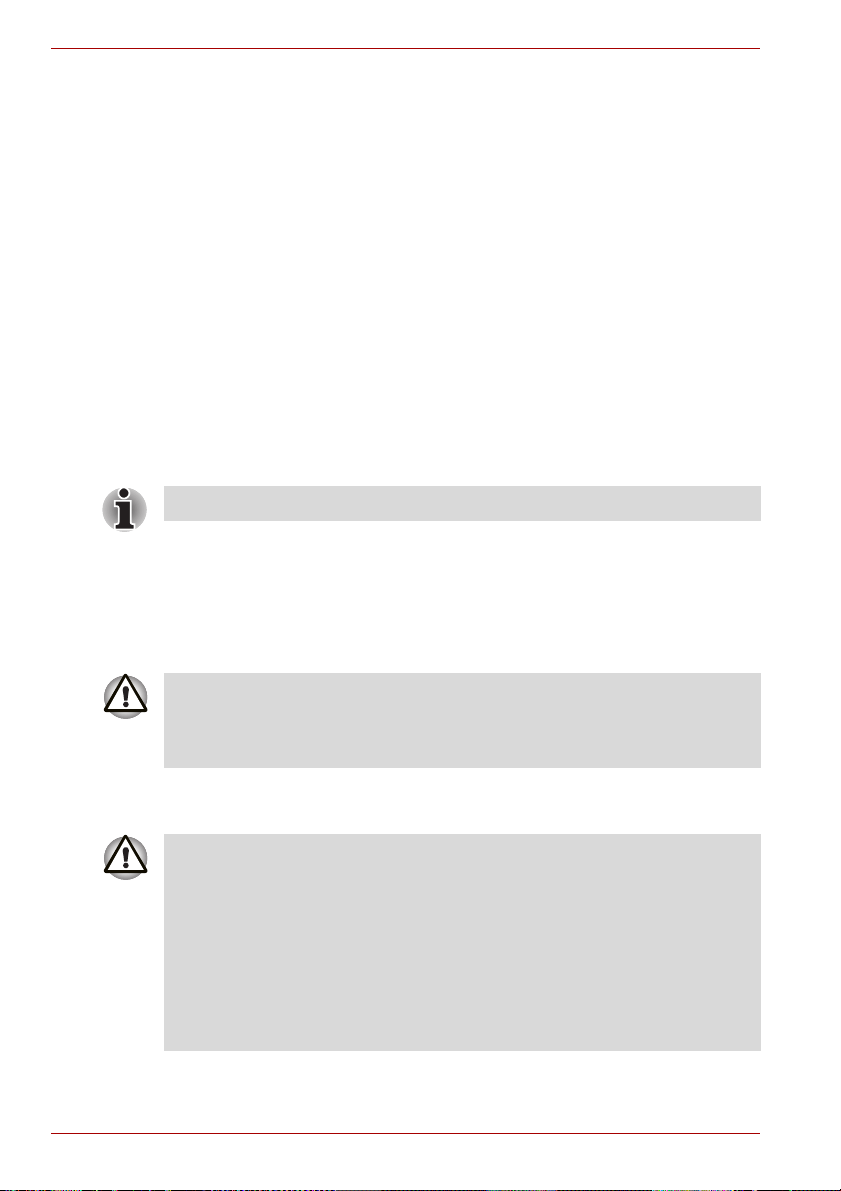
A210 Series
Power indicator
Battery
Battery types
Battery pack
Check the Power indicator to determine the power status.
Blue Indicates power is being supplied to the computer
and the computer is turned on.
Blinking amber Indicates the power was turned off while the
computer was in Resume mode.
No light Under any other conditions, the indicator does not
light.
The computer has two types of batteries:
■ Battery — 3 cell, 6 cell or 9 cell depending on the models
■ Real Time Clock (RTC) battery
Battery pack(3 cell) is used for Intel(R) GM965 model only.
When the AC power cord is not connected, the computer’s main power
source is a removable lithium ion battery pack, also referred to in this
manual as the battery. You can purchase additional battery packs for
extended use of the computer away from an AC power source.
The battery pack is a lithium ion battery, which can explode if not properly
replaced, used, handled or disposed of. Dispose of the battery as required
by local ordinances or regulations. Use only batteries recommended by
TOSHIBA as replacements.
The battery recharges the RTC batteries. The battery maintains the state of
the computer when you enable Resume.
When the computer is powered off in Resume mode, and the AC adaptor is
not connected, the battery pack supply power to maintain data and
programs in memory. If the battery pack is completely discharged, Resume
does not function and the computer loses all data in memory.
The following message appears when you turn on the power:
ERRPR 0271:Check date and time settings.
WARNING 0251:System CMOS checksum bad -
Default configuration used.
Press <F1> to resume, <F2> to Setup.
6-4 User’s Manual

To ensure that the battery pack maintains its maximum capacity, operate
the computer on battery power at least once a month until the battery pack
is fully discharged. Refer to Extending battery life in this chapter for
procedures. If the computer is continuously operated on AC power, more
than a month, the battery may fail to retain a charge. It may not function
efficiently over the expected life of the battery and the Battery LED may not
indicate a low-battery condition.
Real time clock battery
The Real Time Clock (RTC) battery provides power for the internal real
time clock and calendar. It also maintains the system configuration.
If the RTC battery becomes completely discharged, the system loses this
data and the real time clock and calendar stop working. The following
message appears when you turn on the power:
Check system. Then press [F1] key . . . . . .
The computer’s RTC battery is a lithium ion battery and should be replaced
only by your dealer or by a TOSHIBA service representative. The battery
can explode if not properly replaced, used, handled or disposed of.
Dispose of the battery as required by local ordinances or regulations.
Care and use of the battery pack
A210 Series
The battery pack is a vital component of portable computing. Taking proper
care of it will help ensure longer operating time on battery power as well as
a longer life for your battery pack. Follow the instructions in this section
carefully to ensure safe operation and maximum performance.
Safety precautions
Mishandling of batteries can cause death, serious injury or property
damage. Carefully observe the following advisories:
Danger: Indicates an imminently hazardous situation, Which could result in
death or serious injury, if you do not follow instructions.
Warning: Indicates a potentially hazardous situation, Which could result in
death or serious injury, if you do not follow instructions.
Caution: Indicates a potentially hazardous situation, Which if not avoided,
may result in moderate or minor injury or property damage.
Note: Provides important information.
User’s Manual 6-5

A210 Series
Danger
1. Never try to dispose of the battery pack by burning or expose it to a
heating device such as a microwave oven. The battery pack could
explode and cause bodily injury.
2. Never try to disassemble, repair or otherwise tamper with a battery
pack. The battery pack will overheat and ignite. Leakage of caustic
alkaline solution or other electrolytic substances will cause fire or injury,
possibly resulting in death or serious injury.
3. Never short-circuit the battery pack by contacting the terminals with a
metal object. A short-circuit can cause fire or otherwise damage the
battery pack and possibly cause injury. To avoid accidental short-circuit,
always wrap the battery pack in plastic and cover the terminals with
electrical tape when storing or disposing of the battery pack.
4. Never puncture the battery pack with a nail or other sharp object. Never
strike it with a hammer or other object. Never step on it.
5. Never try to change the battery pack in any manner other than that
described in user’s manual. Never connect the battery pack to a plug
socked or to a automobile’s cigarette lighter socket. It may rupture or
ignite.
6. Use only the battery pack supplied with the computer or other device or
an battery pack approved by the computer or device’s manufacturer.
Battery packs have different voltages and terminal polarities. Use of an
improper battery could cause smoke, fire or rupture of the battery pack.
7. Never subject a battery pack to heat, such as storage near a heat
source. Exposure to heat can cause the battery pack to ignite, explode
or leak caustic liquid and cause death or serious injury. It could also fail
or malfunction causing data lose.
8. Never expose the battery pack to abnormal shock, vibration or
pressure. The battery pack’s internal protective device will fail, causing
it to overheat, explode, ignite or leak caustic liquids possibly resulting in
death or serious injury.
9. Never let a battery pack become wet. A wet battery pack will overheat,
ignite or rupture possibly resulting in death or serious injury.
Warning
1. Never allow caustic electrolyte fluid leaked from a battery pack to
contact your eyes, skin or clothing. If caustic electrolyte fluid should
contact your eyes, immediately wash your eyes with large amounts of
running water and seek medical attention, to help prevent eye damage.
It electrolyte fluid should contact your skin immediately wash it under
running water to prevent rash. If it contacts your clothes, promptly
remove them to prevent the fluid from contacting your skin or eyes.
2. Immediately turn off the power, disconnect the AC adaptor and remove
the battery if any of the following events are observed in the battery
pack: offensive or unusual odor, excessive heat, discoloration or
deformation. Never use the computer again until it has been checked
by a TOSHIBA service provider. It might generate smoke or fire, or the
battery pack might rupture.
6-6 User’s Manual

A210 Series
3. Make sure the battery is securely installed in the computer before
attempting to charge the battery pack. Improper installation could
generate smoke or fire, or cause the battery pack to rupture.
4. Keep the battery pack out or reach of infants and children. It can cause
injury.
Caution
1. Never continue to use a battery pack after its recharging capacity has
become impaired, or after the display of a warning message indicating
that the battery pack’s power is exhausted. Continued use of an
exhausted or impaired battery pack could cause the loss of data.
2. Never dispose of battery packs with normal trash. Bring them to your
TOSHIBA dealer or to another recycling center to save resources and
prevent environmental damage. Cover the terminals with electrical tape
to prevent short-circuits, which could cause the battery pack to ignite or
rupture.
3. Use only battery packs recommended by TOSHIBA as replacements.
4. Always make sure the battery pack is installed correctly and securely.
Otherwise, a battery pack could fall out and possibly cause injury.
5. Change the battery pack only in an ambient temperature between 5 and
35 degrees Celsius. Otherwise, the electrolyte solution might leak,
battery pack performance might deteriorate and the battery life might be
shortened.
6. Be sure to monitor the remaining battery power. If the battery pack and
real time clock battery discharge completely. Sleep and Suspend will
not function and data in memory will be lose. Also, the computer might
register an incorrect time and date. In this case, connect the AC adaptor
to recharge the batteries.
7. Never install or remove the battery pack without first turning off the
power and disconnecting the AC adaptor. Never remove the battery
pack while the computer in Suspend or Sleep mode. Data will be lost.
Note
1. Never remove the battery pack while the Wake-up on LAN function is
enabled. Data will be lost. Before you remove a battery pack, disable
the Wake-up on LAN function.
2. To ensure the battery pack maintains maximum capacity, operate the
computer on battery power once a week until the battery pack is fully
discharged. Refer to the section Extending battery life in this chapter for
procedures. If the computer is continuously operated on AC power for
an extended period, more than a week, the battery might fail to retain a
charge. It might not function efficiently over the expected life of the
battery pack and Battery indicator might not indicate a low-battery
condition.
3. After the battery pack is charged, avoid leaving the AC adaptor
connected and the computer turned off for more than a few hours at a
time. Continuing to charge a fully-charged battery pack can damage the
battery.
User’s Manual 6-7

A210 Series
Charging the batteries
When the power in the battery pack becomes low, the Battery indicator
flashes amber indicating that only a few minutes of battery power remain. If
you continue to use the computer while the Battery indicator flashes, the
computer enables Hibernation mode (so you don’t lose data) and
automatically turns off.
The computer enters Hibernate mode only if Hibernation is enabled in two
places: the Hibernate tab in Power Options and Setup Action tab in
TOSHIBA Power Saver.
You must recharge a battery pack when it becomes discharged.
Procedures
To recharge a battery pack while it is installed in the computer, connect the
AC adaptor to the DC IN socket and plug the other end into a working
outlet.
The Battery indicator glows amber when the battery is being charged.
Use only the computer connected to an AC power source or the optional
TOSHIBA Batteries charger to charge the battery pack. Never attempt to
charge the battery pack with any other charger.
Time
The following table shows the approximate time required to fully charge a
discharged battery.
Battery type System on System off
Battery pack (3 cell) 8 hours or more 2 hours
Battery pack (6 cell) 8 hours or more 3 hours
Battery pack (9 cell) 8 hours or more 4 hours
RTC battery 24 hours 24 hours
Charging time (hours)
The charging time when the computer is on is affected by ambient
temperature, the temperature of the computer and how you use the
computer. If you make heavy use of external devices, for example, the
battery might scarcely charge at all during operation. Refer also to the
section Maximizing battery operating time.
.
6-8 User’s Manual

A210 Series
Battery charging notice
The battery may not charge right away under the following conditions:
■ The battery is extremely hot or cold. If the battery is extremely hot, it
might not charge at all. Also, to ensure the battery charges to its full
capacity, charge the battery at room temperature of 10° to 30°C
(50° to 86°F).
■ The battery is nearly completely discharged. Leave the AC adaptor
connected for a few minutes and the battery should begin charging.
The Battery indicator may show a rapid decrease in battery operating time
when you try to charge a battery under the following conditions:
■ The battery has not been used for a long time.
■ The battery has completely discharged and been left in the computer for
a long time.
■ A cool battery is installed in a warm computer.
In such case, follow the steps below.
1. Fully discharge the battery by leaving it in the computer with the power
on until the power automatically shuts off.
2. Plug in the AC adaptor.
3. Charge the battery until the Battery indicator glows blue.
Repeat the steps two or three times until the battery recovers normal
capacity.
Leaving the AC adaptor connected will shorten battery life. At least once a
month, run the computer on battery power until the battery is fully
discharged, then recharged the battery.
Monitoring battery capacity
Remaining battery power can be monitored in TOSHIBA Power Saver.
■ Wait at least 16 seconds after turning on the computer before trying to
monitor the remaining operating time. The computer needs this time to
check the battery’s remaining capacity and to calculate the remaining
operating time, based on the current power consumption rate and
remaining battery capacity. The actual remaining operating time may
differ slightly from the calculated time.
■ With repeated discharges and recharges, the battery’s capacity will
gradually decrease. Therefore, an often used, older battery will not
operate for as long as a new battery even when both are fully charged.
In this case, TOSHIBA Power Saver will indicate a 100% charge for
both the old and new battery, but the displayed estimated time
remaining will be shorter for the older battery.
User’s Manual 6-9

A210 Series
Maximizing battery operating time
A battery’s usefulness depends on how long it can supply power on a
single charge.
How long the charge lasts in a battery depends on:
■ How you configure the computer (for example, whether you enable
battery-power saving options). The computer provides a battery save
mode, which can be set in TOSHIBA Power Saver, to conserve battery
power. This mode has the following options:
■ CPU Precessing speed
■ Screen brightness
■ Cooling Method
■ System Sleep
■ System Hibernation
■ Monitor Power off
■ HDD Power off
■ How often and how long you use the hard disk, CD/DVD-ROM drive
and the diskette drive.
■ How much charge the battery contained to begin with.
■ How you use optional devices, such as an Express Card, to which the
battery supplies power.
■ Enabling Resume mode conserves battery power if you are frequently
turning the computer off and on.
■ Where you store your programs and data.
■ Closing the display when you are not using the keyboard saves power.
■ Operating time decreases at low temperatures.
■ The condition of the battery terminals. Make sure the battery terminals
stay clean by wiping them with a clean dry cloth before installing the
battery pack.
Retaining data with power off
When you turn off your computer with fully charged batteries, the batteries
retain data for the following approximate time periods:
Battery pack (3 cell) about 1.8 days (Sleep mode)
about 15 days (Shutdown mode)
Battery pack (6 cell) about 3.5 days (Sleep mode)
about 30 days (Shutdown mode)
Battery pack (9 cell) about 5.5 days (Sleep mode)
about 50 days (Shutdown mode)
RTC battery about 3 months
6-10 User’s Manual
 Loading...