


User’s Manual
Tecra A2
Choose freedom.Choose freedom.
computers.toshiba-europe.com

Copyright
© 2004 by TOSHIBA Corporation. All rights reserved. Under the copyright
laws, this manual cannot be reproduced in any form without the prior
written permission of TOSHIBA. No patent liability is assumed, with respect
to the use of the information contained herein.
TOSHIBA TECRA A2 Portable Personal Computer User’s Manual
First edition May 2004
Copyright authority for music, movies, computer programs, data bases and
other intellectual property covered by copyright laws belongs to the author
or to the copyright owner. Copyrighted material can be reproduced only for
personal use or use within the home. Any other use beyond that stipulated
above (including conversion to digital format, alteration, transfer of copied
material and distribution on a network) without the permission of the
copyright owner is a violation of copyright or author’s rights and is subject
to civil damages or criminal action. Please comply with copyright laws in
making any reproduction from this manual.
Disclaimer
This manual has been validated and reviewed for accuracy. The
instructions and descriptions it contains are accurate for the TOSHIBA
TECRA A2 Portable Personal Computer at the time of this manual’s
production. However, succeeding computers and manuals are subject to
change without notice. TOSHIBA assumes no liability for damages incurred
directly or indirectly from errors, omissions or discrepancies between the
computer and the manual.
User’s Manual
Trademarks
Intel, Intel SpeedStep, Pentium and Celeron are trademarks or registered
trademarks of Intel Corporation.
Windows and Microsoft are registered trademarks of Microsoft Corporation.
Photo CD is a trademark of Eastman Kodak.
Other trademarks and registered trademarks not listed above may be used
in this manual.
User’s Manual ii

EU Declaration of Conformity
This product is carrying the CE-Mark in accordance with the related
European Directives. Responsible for CE-Marking is TOSHIBA Europe
GmbH, Hammfelddamm 8, 41460 Neuss, Germany.
The complete and official EU Declaration of Conformity can be found on
TOSHIBA’s web site http://epps.toshiba-te
Modem warning notice
Conformity Statement
The equipment has been approved to [Commission Decision “CTR21”] for
pan-European single terminal connection to the Public Switched Telephone
Network (PSTN).
However, due to differences between the individual PSTNs provided in
different countries/regions the approval does not, of itself, give an
unconditional assurance of successful operation on every PSTN network
termination point.
In the event of problems, you should contact your equipment supplier in the
first instance.
Network Compatibility Statement
This product is designed to work with, and is compatible with the following
networks. It has been tested to and found to conform with the additional
requirements conditional in EG 201 121.
Germany ATAAB AN005,AN006,AN007,AN009,AN010 and
DE03,04,05,08,09,12,14,17
Greece ATAAB AN005,AN006 and GR01,02,03,04
Portugal ATAAB AN001,005,006,007,011 and P03,04,08,10
Spain ATAAB AN005,007,012, and ES01
Switzerland ATAAB AN002
All other countries/ ATAAB AN003,004
regions
Specific switch settings or software setup are required for each network,
please refer to the relevant sections of the user guide for more details.
The hookflash (timed break register recall) function is subject to separate
national type approvals. It has not been tested for conformity to national
type regulations, and no guarantee of successful operation of that specific
function on specific national networks can be given.
User’s Manual
g.com on the Internet.
User’s Manual iii

Optical Disc drive safety Instructions
Description on Laser specification
Be sure to check the international precautions at the end of this section.
The optical drive such as DVD-ROM drive, DVD-ROM&CD-R/RW drive,
DVD -R/-RW Drive, and DVD Super Multi drive that is used in this computer
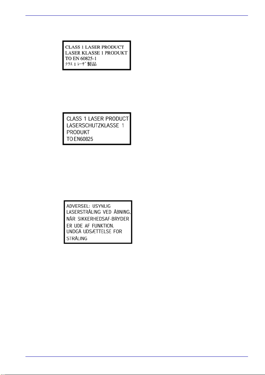
is equipped with laser. The classification label with the following sentence is
affixed to the surface of the drive.
CLASS 1 LASER PRODUCT
LASER KLASSE 1
LUOKAN 1 LASERLAITE
APPAREIL A LASER DE CLASSE 1
KLASS 1 LASER APPARAT
The drive with the above label is certified by the manufacturer that the drive
complies with the requirement for laser product on the date of
manufacturing pursuant to article 21 of Code of Federal Regulations by the
United States of America, Department of Health & Human Services, Food
and Drug Administration.
In other countries, the drive is certified to comply with the requirement
pursuant to IEC 825 and EN60825 on class 1 laser product.
This computer is equipped with one of the optical drive in the following list
according to the model.
User’s Manual
Manufacturer Type
TEAC DVD Super Multi DV-W24E
Toshiba DVD-ROM SD-C2612
Toshiba DVD-ROM&CD-R/RW SD-R2512
Toshiba DVD-R/-RW SD-R6112
HITACHI LG DVD-ROM&CD-R/RW GCC-4241N
Panasonic DVD-ROM&CD-R/RW UJDA750
Panasonic DVD Super Multi UJ-820
User’s Manual iv
International precautions
The optical disc drive employs a laser system. To ensure proper use of this
product, please read this instruction manual carefully and retain for future
reference. Should the unit ever require maintenance, contact an
authorized service location.
Use of controls, adjustments or the performance of procedures other than
those specified may result in hazardous radiation exposure.
To prevent direct exposure to the laser beam, do not try to open the
enclosure.
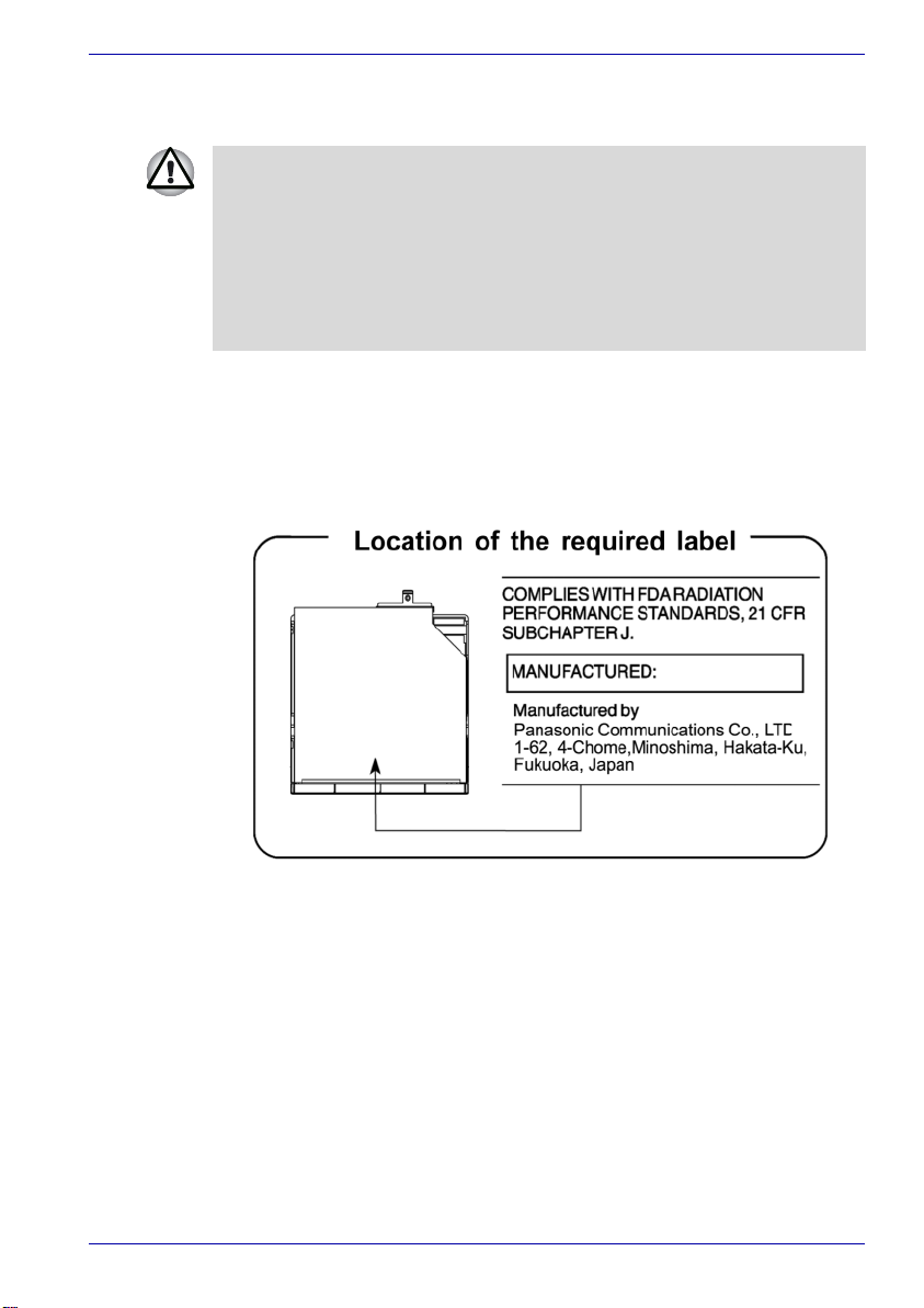
Location of the required label
Sample shown below. Location of the label on the drive and manufacturing
information may vary.
User’s Manual
User’s Manual v
User’s Manual
CAUTION: This appliance contains a
laser system and is classified as a
“CLASS 1 LASER PRODUCT.” To use
this model properly, read the instruction
manual carefully and keep this manual
for your future reference. In case of any
trouble with this model, please contact
your nearest “AUTHORIZED service
station.” To prevent direct exposure to the
laser beam, do not try to open the
enclosure.
VORSICHT: Dieses Gerät enthält ein
Laser-System und ist als
“LASERSCHUTZKLASSE 1 PRODUKT”
klassifiziert. Für den richtigen Gebrauch
dieses Modells lesen Sie bitte die
Bedienungsanleitung sorgfältig durch
und bewahren diese bitte als Referenz
auf. Falls Probleme mit diesem Modell
auftreten, benachrichtigen Sie bitte die
nächste “autorisierte Service-Vertretung”.
Um einen direkten Kontakt mit dem
Laserstrahl zu vermeiden darf das Gerät
nicht geöffnet werden.
ADVARSEL: Denne mærking er anbragt
udvendigt på apparatet og indikerer, at
apparatet arbejder med laserstråler af
klasse 1, hviket betyder, at der anvendes
laserstrlier af svageste klasse, og at man
ikke på apparatets yderside kan bilve
udsat for utilladellg kraftig stråling.
APPARATET BOR KUN ÅBNES AF
FAGFOLK MED SÆRLIGT KENDSKAB
TIL APPARATER MED
LASERSTRÅLER!
Indvendigt i apparatet er anbragt den her
gengivne advarselsmækning, som
advarer imod at foretage sådanne
indgreb i apparatet, at man kan komme til
at udsatte sig for laserstråling.
User’s Manual vi

User’s Manual
OBS! Apparaten innehåller
laserkomponent som avger laserstråining
överstigande gränsen för laserklass 1.
VAROITUS. Suojakoteloa si saa avata.
Laite sisältää laserdiodin, joka lähetää
näkymätöntä silmilie vaarallista
lasersäteilyä.
CAUTION: USE OF CONTROLS OR
ADJUSTMENTS OR PERFORMANCE
OF PROCEDURES OTHER THAN
THOSE SPECIFIED IN THE OWNER’S
MANUAL MAY RESULT IN
HAZARDOUS RADIATION EXPOSURE.
VORSICHT: DIE VERWENDUNG VON
ANDEREN STEURUNGEN ODER
EINSTELLUNGEN ODER DAS
DURCHFÜHREN VON ANDEREN
VORGÄNGEN ALS IN DER
BEDIENUNGSANLEITUNG
BESCHRIEBEN KÖNNEN
GEFÄHRLICHE
STRAHLENEXPOSITIONEN ZUR
FOLGE HABEN.
User’s Manual vii

TECRA A2
Table of Contents
Preface
Manual contents . . . . . . . . . . . . . . . . . . . . . . . . . . . . . . . . . . . . . . . . . . xiv
Conventions. . . . . . . . . . . . . . . . . . . . . . . . . . . . . . . . . . . . . . . . . . . . . . .xv
Abbreviations. . . . . . . . . . . . . . . . . . . . . . . . . . . . . . . . . . . . . . . . . . . . xv
Icons . . . . . . . . . . . . . . . . . . . . . . . . . . . . . . . . . . . . . . . . . . . . . . . . . . xv
Keys. . . . . . . . . . . . . . . . . . . . . . . . . . . . . . . . . . . . . . . . . . . . . . . . . . . xv
Key operation . . . . . . . . . . . . . . . . . . . . . . . . . . . . . . . . . . . . . . . . . . xvi
Display. . . . . . . . . . . . . . . . . . . . . . . . . . . . . . . . . . . . . . . . . . . . . . . . xvi
Messages . . . . . . . . . . . . . . . . . . . . . . . . . . . . . . . . . . . . . . . . . . . . . xvi
General Precautions
Stress injury. . . . . . . . . . . . . . . . . . . . . . . . . . . . . . . . . . . . . . . . . . . . xvii
Heat warning . . . . . . . . . . . . . . . . . . . . . . . . . . . . . . . . . . . . . . . . . . . xvii
Pressure or impact damage. . . . . . . . . . . . . . . . . . . . . . . . . . . . . . . . xvii
PC Card overheating . . . . . . . . . . . . . . . . . . . . . . . . . . . . . . . . . . . . .xviii
Mobile phones . . . . . . . . . . . . . . . . . . . . . . . . . . . . . . . . . . . . . . . . . .xviii
Central Processing Unit ("CPU") Performance Disclaimer . . . . . . . . xviii
RTC battery . . . . . . . . . . . . . . . . . . . . . . . . . . . . . . . . . . . . . . . . . . . .xviii
Introduction
Equipment checklist . . . . . . . . . . . . . . . . . . . . . . . . . . . . . . . . . . . . . . . 1-1
Hardware . . . . . . . . . . . . . . . . . . . . . . . . . . . . . . . . . . . . . . . . . . . . . . 1-1
Software. . . . . . . . . . . . . . . . . . . . . . . . . . . . . . . . . . . . . . . . . . . . . . . 1-2
Features . . . . . . . . . . . . . . . . . . . . . . . . . . . . . . . . . . . . . . . . . . . . . . . . . 1-3
Special features. . . . . . . . . . . . . . . . . . . . . . . . . . . . . . . . . . . . . . . . . . . 1-9
Utilities . . . . . . . . . . . . . . . . . . . . . . . . . . . . . . . . . . . . . . . . . . . . . . . . . 1-12
Options. . . . . . . . . . . . . . . . . . . . . . . . . . . . . . . . . . . . . . . . . . . . . . . . . 1-14
The Grand Tour
Front with the display closed. . . . . . . . . . . . . . . . . . . . . . . . . . . . . . . . 2-1
Left side . . . . . . . . . . . . . . . . . . . . . . . . . . . . . . . . . . . . . . . . . . . . . . . . . 2-2
Right side. . . . . . . . . . . . . . . . . . . . . . . . . . . . . . . . . . . . . . . . . . . . . . . . 2-3
Backside. . . . . . . . . . . . . . . . . . . . . . . . . . . . . . . . . . . . . . . . . . . . . . . . . 2-5
Underside. . . . . . . . . . . . . . . . . . . . . . . . . . . . . . . . . . . . . . . . . . . . . . . . 2-6
User’s Manual viii

Front with the display open . . . . . . . . . . . . . . . . . . . . . . . . . . . . . . . . . 2-7
System indicators . . . . . . . . . . . . . . . . . . . . . . . . . . . . . . . . . . . . . . . 2-10
Keyboard indicators . . . . . . . . . . . . . . . . . . . . . . . . . . . . . . . . . . . . . . 2-11
USB floppy disk drive (optional) . . . . . . . . . . . . . . . . . . . . . . . . . . . . 2-12
Fixed optical media drives . . . . . . . . . . . . . . . . . . . . . . . . . . . . . . . . . 2-13
Region codes for DVD drives and media . . . . . . . . . . . . . . . . . . . . 2-13
Writable discs . . . . . . . . . . . . . . . . . . . . . . . . . . . . . . . . . . . . . . . . . 2-13
CDs . . . . . . . . . . . . . . . . . . . . . . . . . . . . . . . . . . . . . . . . . . . . . . . . . 2-13
DVDs . . . . . . . . . . . . . . . . . . . . . . . . . . . . . . . . . . . . . . . . . . . . . . . . 2-14
Formats . . . . . . . . . . . . . . . . . . . . . . . . . . . . . . . . . . . . . . . . . . . . . . 2-14
DVD-ROM drive. . . . . . . . . . . . . . . . . . . . . . . . . . . . . . . . . . . . . . . . 2-14
DVD-ROM&CD-R/RW drive . . . . . . . . . . . . . . . . . . . . . . . . . . . . . . 2-14
DVD-R/-RW drive . . . . . . . . . . . . . . . . . . . . . . . . . . . . . . . . . . . . . . 2-15
DVD Super Multi drive . . . . . . . . . . . . . . . . . . . . . . . . . . . . . . . . . . . 2-15
AC adaptor. . . . . . . . . . . . . . . . . . . . . . . . . . . . . . . . . . . . . . . . . . . . . . 2-16
Getting Started
Setting up your work space . . . . . . . . . . . . . . . . . . . . . . . . . . . . . . . . . 3-1
General conditions. . . . . . . . . . . . . . . . . . . . . . . . . . . . . . . . . . . . . . . 3-2
Placement of the computer . . . . . . . . . . . . . . . . . . . . . . . . . . . . . . . . 3-2
Seating and posture . . . . . . . . . . . . . . . . . . . . . . . . . . . . . . . . . . . . . 3-3
Lighting . . . . . . . . . . . . . . . . . . . . . . . . . . . . . . . . . . . . . . . . . . . . . . . 3-3
Work habits . . . . . . . . . . . . . . . . . . . . . . . . . . . . . . . . . . . . . . . . . . . . 3-4
Installing the battery pack . . . . . . . . . . . . . . . . . . . . . . . . . . . . . . . . . . 3-4
Connecting the AC adaptor . . . . . . . . . . . . . . . . . . . . . . . . . . . . . . . . . 3-5
Opening the display . . . . . . . . . . . . . . . . . . . . . . . . . . . . . . . . . . . . . . . 3-6
Turning on the power . . . . . . . . . . . . . . . . . . . . . . . . . . . . . . . . . . . . . . 3-7
Windows XP setup . . . . . . . . . . . . . . . . . . . . . . . . . . . . . . . . . . . . . . . . 3-8
Turning off the power . . . . . . . . . . . . . . . . . . . . . . . . . . . . . . . . . . . . . . 3-8
Shut Down mode (Boot mode) . . . . . . . . . . . . . . . . . . . . . . . . . . . . . 3-8
Hibernation Mode . . . . . . . . . . . . . . . . . . . . . . . . . . . . . . . . . . . . . . . 3-8
Standby Mode . . . . . . . . . . . . . . . . . . . . . . . . . . . . . . . . . . . . . . . . . 3-10
Restarting the computer. . . . . . . . . . . . . . . . . . . . . . . . . . . . . . . . . . . 3-11
Restoring preinstalled software. . . . . . . . . . . . . . . . . . . . . . . . . . . . . 3-12
Restoring from the Product Recovery Media. . . . . . . . . . . . . . . . . . 3-12
Restoring from Recovery HDD . . . . . . . . . . . . . . . . . . . . . . . . . . . . 3-13
Operating Basics
Using the Touch pad . . . . . . . . . . . . . . . . . . . . . . . . . . . . . . . . . . . . . . . 4-1
Using the USB floppy disk drive (optional) . . . . . . . . . . . . . . . . . . . . 4-2
Connecting 3 1/2" floppy disk drive . . . . . . . . . . . . . . . . . . . . . . . . . . 4-2
Disconnecting 3 1/2" floppy disk drive. . . . . . . . . . . . . . . . . . . . . . . . 4-3
User’s Manual ix

Using optical media drives. . . . . . . . . . . . . . . . . . . . . . . . . . . . . . . . . . 4-3
Loading discs. . . . . . . . . . . . . . . . . . . . . . . . . . . . . . . . . . . . . . . . . . . 4-4
Removing discs . . . . . . . . . . . . . . . . . . . . . . . . . . . . . . . . . . . . . . . . . 4-6
Writing CDs on DVD-ROM&CD-R/RW drive . . . . . . . . . . . . . . . . . . . . 4-7
Before writing or rewriting . . . . . . . . . . . . . . . . . . . . . . . . . . . . . . . . . 4-7
When writing or rewriting . . . . . . . . . . . . . . . . . . . . . . . . . . . . . . . . . . 4-8
Writing CD/DVDs on DVD-R/-RW drive . . . . . . . . . . . . . . . . . . . . . . . . 4-8
Writing CD/DVDs on DVD Super Multi drive. . . . . . . . . . . . . . . . . . . . 4-8
Important message (DVD-R/-RW drive) . . . . . . . . . . . . . . . . . . . . . . 4-9
Important message (DVD Super Multi drive) . . . . . . . . . . . . . . . . . . . 4-9
Disclaimer (DVD-R/-RW drive) . . . . . . . . . . . . . . . . . . . . . . . . . . . . . 4-9
Disclaimer (DVD Super Multi drive). . . . . . . . . . . . . . . . . . . . . . . . . . 4-9
Before writing or rewriting . . . . . . . . . . . . . . . . . . . . . . . . . . . . . . . . 4-10
When writing or rewriting . . . . . . . . . . . . . . . . . . . . . . . . . . . . . . . . . 4-11
RecordNow! Basic for TOSHIBA . . . . . . . . . . . . . . . . . . . . . . . . . . . 4-12
Data Verification. . . . . . . . . . . . . . . . . . . . . . . . . . . . . . . . . . . . . . . . 4-13
DLA for TOSHIBA . . . . . . . . . . . . . . . . . . . . . . . . . . . . . . . . . . . . . . 4-13
Video . . . . . . . . . . . . . . . . . . . . . . . . . . . . . . . . . . . . . . . . . . . . . . . . 4-13
When WinDVD Creator 2 Platinum is used: . . . . . . . . . . . . . . . . . . 4-14
Media care . . . . . . . . . . . . . . . . . . . . . . . . . . . . . . . . . . . . . . . . . . . . . . 4-15
CD/DVDs . . . . . . . . . . . . . . . . . . . . . . . . . . . . . . . . . . . . . . . . . . . . . 4-15
Floppy disks. . . . . . . . . . . . . . . . . . . . . . . . . . . . . . . . . . . . . . . . . . . 4-15
Sound System . . . . . . . . . . . . . . . . . . . . . . . . . . . . . . . . . . . . . . . . . . . 4-15
Volume control . . . . . . . . . . . . . . . . . . . . . . . . . . . . . . . . . . . . . . . . . 4-16
Microphone level . . . . . . . . . . . . . . . . . . . . . . . . . . . . . . . . . . . . . . . 4-16
Audio controller . . . . . . . . . . . . . . . . . . . . . . . . . . . . . . . . . . . . . . . . 4-16
Modem . . . . . . . . . . . . . . . . . . . . . . . . . . . . . . . . . . . . . . . . . . . . . . . . . 4-17
Region selection . . . . . . . . . . . . . . . . . . . . . . . . . . . . . . . . . . . . . . . 4-17
Properties menu . . . . . . . . . . . . . . . . . . . . . . . . . . . . . . . . . . . . . . . 4-17
Setting . . . . . . . . . . . . . . . . . . . . . . . . . . . . . . . . . . . . . . . . . . . . . . . 4-17
Modem Selection. . . . . . . . . . . . . . . . . . . . . . . . . . . . . . . . . . . . . . . 4-18
Dialing Properties . . . . . . . . . . . . . . . . . . . . . . . . . . . . . . . . . . . . . . 4-18
Connecting . . . . . . . . . . . . . . . . . . . . . . . . . . . . . . . . . . . . . . . . . . . 4-18
Disconnecting . . . . . . . . . . . . . . . . . . . . . . . . . . . . . . . . . . . . . . . . . 4-19
Wireless LAN . . . . . . . . . . . . . . . . . . . . . . . . . . . . . . . . . . . . . . . . . . . . 4-20
Wireless communication switch. . . . . . . . . . . . . . . . . . . . . . . . . . . . 4-20
Wireless communication indicator . . . . . . . . . . . . . . . . . . . . . . . . . . 4-21
LAN . . . . . . . . . . . . . . . . . . . . . . . . . . . . . . . . . . . . . . . . . . . . . . . . . . . 4-21
LAN cable types . . . . . . . . . . . . . . . . . . . . . . . . . . . . . . . . . . . . . . . 4-21
Connecting LAN cable. . . . . . . . . . . . . . . . . . . . . . . . . . . . . . . . . . . 4-22
Disconnecting LAN cable . . . . . . . . . . . . . . . . . . . . . . . . . . . . . . . . 4-22
Cleaning the computer . . . . . . . . . . . . . . . . . . . . . . . . . . . . . . . . . . . . 4-23
Moving the computer . . . . . . . . . . . . . . . . . . . . . . . . . . . . . . . . . . . . . 4-23
Heat dispersal . . . . . . . . . . . . . . . . . . . . . . . . . . . . . . . . . . . . . . . . . . . 4-24
User’s Manual x

The Keyboard
Typewriter keys . . . . . . . . . . . . . . . . . . . . . . . . . . . . . . . . . . . . . . . . . . . 5-1
F1 … F12 function keys . . . . . . . . . . . . . . . . . . . . . . . . . . . . . . . . . . . . 5-2
Soft keys: Fn key combinations . . . . . . . . . . . . . . . . . . . . . . . . . . . . . 5-2
Emulating keys on enhanced keyboard. . . . . . . . . . . . . . . . . . . . . . . 5-2
Hot keys . . . . . . . . . . . . . . . . . . . . . . . . . . . . . . . . . . . . . . . . . . . . . . . . . 5-3
Fn Sticky key . . . . . . . . . . . . . . . . . . . . . . . . . . . . . . . . . . . . . . . . . . . 5-6
Windows special keys . . . . . . . . . . . . . . . . . . . . . . . . . . . . . . . . . . . . . 5-6
Keypad overlay . . . . . . . . . . . . . . . . . . . . . . . . . . . . . . . . . . . . . . . . . . . 5-6
Turning on the overlays . . . . . . . . . . . . . . . . . . . . . . . . . . . . . . . . . . . 5-7
Temporarily using normal keyboard (overlay on). . . . . . . . . . . . . . . . 5-7
Temporarily using overlay (overlay off) . . . . . . . . . . . . . . . . . . . . . . . 5-8
Temporarily changing modes. . . . . . . . . . . . . . . . . . . . . . . . . . . . . . . 5-8
Generating ASCII characters . . . . . . . . . . . . . . . . . . . . . . . . . . . . . . . . 5-8
Power and Power-Up Modes
Power conditions . . . . . . . . . . . . . . . . . . . . . . . . . . . . . . . . . . . . . . . . . 6-1
Power indicators . . . . . . . . . . . . . . . . . . . . . . . . . . . . . . . . . . . . . . . . . . 6-3
Battery indicator. . . . . . . . . . . . . . . . . . . . . . . . . . . . . . . . . . . . . . . . . 6-3
DC IN 15V indicator. . . . . . . . . . . . . . . . . . . . . . . . . . . . . . . . . . . . . . 6-3
Power indicator . . . . . . . . . . . . . . . . . . . . . . . . . . . . . . . . . . . . . . . . . 6-4
Battery types . . . . . . . . . . . . . . . . . . . . . . . . . . . . . . . . . . . . . . . . . . . . . 6-4
High Capacity battery pack . . . . . . . . . . . . . . . . . . . . . . . . . . . . . . . . 6-4
Battery pack. . . . . . . . . . . . . . . . . . . . . . . . . . . . . . . . . . . . . . . . . . . . 6-5
Real Time Clock battery . . . . . . . . . . . . . . . . . . . . . . . . . . . . . . . . . . 6-6
Care and use of the battery pack . . . . . . . . . . . . . . . . . . . . . . . . . . . . . 6-6
Safety precautions. . . . . . . . . . . . . . . . . . . . . . . . . . . . . . . . . . . . . . . 6-6
Charging the batteries . . . . . . . . . . . . . . . . . . . . . . . . . . . . . . . . . . . . 6-9
Monitoring battery capacity . . . . . . . . . . . . . . . . . . . . . . . . . . . . . . . 6-11
Maximizing battery operating time. . . . . . . . . . . . . . . . . . . . . . . . . . 6-11
Retaining data with power off . . . . . . . . . . . . . . . . . . . . . . . . . . . . . 6-12
Extending battery life . . . . . . . . . . . . . . . . . . . . . . . . . . . . . . . . . . . . 6-12
Replacing the battery pack. . . . . . . . . . . . . . . . . . . . . . . . . . . . . . . . . 6-13
Removing the battery pack . . . . . . . . . . . . . . . . . . . . . . . . . . . . . . . 6-13
Installing the battery pack . . . . . . . . . . . . . . . . . . . . . . . . . . . . . . . . 6-15
Starting the computer by password . . . . . . . . . . . . . . . . . . . . . . . . . 6-16
Power-up modes . . . . . . . . . . . . . . . . . . . . . . . . . . . . . . . . . . . . . . . . . 6-16
Windows utilities . . . . . . . . . . . . . . . . . . . . . . . . . . . . . . . . . . . . . . . 6-16
Hot keys. . . . . . . . . . . . . . . . . . . . . . . . . . . . . . . . . . . . . . . . . . . . . . 6-16
Panel power on/off . . . . . . . . . . . . . . . . . . . . . . . . . . . . . . . . . . . . . . . 6-17
System Auto Off . . . . . . . . . . . . . . . . . . . . . . . . . . . . . . . . . . . . . . . . . 6-17
HW Setup and Passwords
HW Setup . . . . . . . . . . . . . . . . . . . . . . . . . . . . . . . . . . . . . . . . . . . . . . . . 7-1
User’s Manual xi

Accessing HW Setup . . . . . . . . . . . . . . . . . . . . . . . . . . . . . . . . . . . . . . 7-1
HW Setup window . . . . . . . . . . . . . . . . . . . . . . . . . . . . . . . . . . . . . . . 7-1
Optional Devices
PC Card . . . . . . . . . . . . . . . . . . . . . . . . . . . . . . . . . . . . . . . . . . . . . . . . . 8-2
Inserting a PC Card . . . . . . . . . . . . . . . . . . . . . . . . . . . . . . . . . . . . . . 8-2
Removing a PC Card. . . . . . . . . . . . . . . . . . . . . . . . . . . . . . . . . . . . . 8-3
Memory expansion . . . . . . . . . . . . . . . . . . . . . . . . . . . . . . . . . . . . . . . . 8-3
Installing a memory module. . . . . . . . . . . . . . . . . . . . . . . . . . . . . . . . 8-4
Removing a memory module. . . . . . . . . . . . . . . . . . . . . . . . . . . . . . . 8-5
Additional battery pack. . . . . . . . . . . . . . . . . . . . . . . . . . . . . . . . . . . . . 8-6
Additional AC adaptor . . . . . . . . . . . . . . . . . . . . . . . . . . . . . . . . . . . . . 8-6
Battery charger . . . . . . . . . . . . . . . . . . . . . . . . . . . . . . . . . . . . . . . . . . . 8-7
USB floppy disk drive . . . . . . . . . . . . . . . . . . . . . . . . . . . . . . . . . . . . . . 8-7
External monitor . . . . . . . . . . . . . . . . . . . . . . . . . . . . . . . . . . . . . . . . . . 8-7
Parallel printer . . . . . . . . . . . . . . . . . . . . . . . . . . . . . . . . . . . . . . . . . . . . 8-7
Advanced Port Replicator IIl . . . . . . . . . . . . . . . . . . . . . . . . . . . . . . . . 8-8
Connecting the Port Replicator . . . . . . . . . . . . . . . . . . . . . . . . . . . . . 8-9
Security lock . . . . . . . . . . . . . . . . . . . . . . . . . . . . . . . . . . . . . . . . . . . . 8-10
Troubleshooting
Problem solving process . . . . . . . . . . . . . . . . . . . . . . . . . . . . . . . . . . . 9-1
Preliminary checklist . . . . . . . . . . . . . . . . . . . . . . . . . . . . . . . . . . . . . 9-2
Analyzing the problem . . . . . . . . . . . . . . . . . . . . . . . . . . . . . . . . . . . . 9-2
Hardware and system checklist. . . . . . . . . . . . . . . . . . . . . . . . . . . . . . 9-3
System start-up . . . . . . . . . . . . . . . . . . . . . . . . . . . . . . . . . . . . . . . . . 9-3
Self test . . . . . . . . . . . . . . . . . . . . . . . . . . . . . . . . . . . . . . . . . . . . . . . 9-4
Power . . . . . . . . . . . . . . . . . . . . . . . . . . . . . . . . . . . . . . . . . . . . . . . . 9-4
Password. . . . . . . . . . . . . . . . . . . . . . . . . . . . . . . . . . . . . . . . . . . . . . 9-7
Keyboard . . . . . . . . . . . . . . . . . . . . . . . . . . . . . . . . . . . . . . . . . . . . . 9-7
LCD panel . . . . . . . . . . . . . . . . . . . . . . . . . . . . . . . . . . . . . . . . . . . . . 9-7
Hard disk drive. . . . . . . . . . . . . . . . . . . . . . . . . . . . . . . . . . . . . . . . . . 9-8
DVD-ROM drive. . . . . . . . . . . . . . . . . . . . . . . . . . . . . . . . . . . . . . . . . 9-8
DVD-ROM&CD-R/RW drive . . . . . . . . . . . . . . . . . . . . . . . . . . . . . . 9-10
DVD-R/-RW drive . . . . . . . . . . . . . . . . . . . . . . . . . . . . . . . . . . . . . . 9-11
DVD Super Multi drive . . . . . . . . . . . . . . . . . . . . . . . . . . . . . . . . . . . 9-13
Floppy disk drive . . . . . . . . . . . . . . . . . . . . . . . . . . . . . . . . . . . . . . . 9-14
PC Card. . . . . . . . . . . . . . . . . . . . . . . . . . . . . . . . . . . . . . . . . . . . . . 9-14
Pointing device . . . . . . . . . . . . . . . . . . . . . . . . . . . . . . . . . . . . . . . . 9-15
USB . . . . . . . . . . . . . . . . . . . . . . . . . . . . . . . . . . . . . . . . . . . . . . . . . 9-16
Memory expansion . . . . . . . . . . . . . . . . . . . . . . . . . . . . . . . . . . . . . 9-17
Sound system . . . . . . . . . . . . . . . . . . . . . . . . . . . . . . . . . . . . . . . . . 9-18
Monitor. . . . . . . . . . . . . . . . . . . . . . . . . . . . . . . . . . . . . . . . . . . . . . . 9-18
Modem. . . . . . . . . . . . . . . . . . . . . . . . . . . . . . . . . . . . . . . . . . . . . . . 9-19
User’s Manual xii

LAN . . . . . . . . . . . . . . . . . . . . . . . . . . . . . . . . . . . . . . . . . . . . . . . . . 9-20
Wireless LAN. . . . . . . . . . . . . . . . . . . . . . . . . . . . . . . . . . . . . . . . . . 9-20
Printer . . . . . . . . . . . . . . . . . . . . . . . . . . . . . . . . . . . . . . . . . . . . . . . 9-20
TOSHIBA support . . . . . . . . . . . . . . . . . . . . . . . . . . . . . . . . . . . . . . . . 9-21
Before you call. . . . . . . . . . . . . . . . . . . . . . . . . . . . . . . . . . . . . . . . . 9-21
Appendix A Specifications
Appendix B Display Controller and Modes
Appendix C Internal Modem Guide
Appendix D Wireless LAN
Appendix E AC Power Cord and Connectors
Appendix F If your computer is stolen
Glossary
Index
User’s Manual xiii

TECRA A2
Preface
Congratulations on your purchase of the TECRA A2 computer. This
powerful notebook computer provides excellent expansion capability,
including multimedia devices, and it is designed to provide years of reliable,
high-performance computing.
This manual tells how to set up and begin using your TECRA A2 computer.
It also provides detailed information on configuring your computer, basic
operations and care, using optional devices and troubleshooting.
If you are a new user of computers or if you’re new to portable computing,
first read over the Introduction and The Grand Tour chapters to familiarize
yourself with the computer’s features, components and accessory devices.
Then read Getting Started for step-by-step instructions on setting up your
computer.
If you are an experienced computer user, please continue reading the
preface to learn how this manual is organized, then become acquainted
with this manual by browsing through its pages. Be sure to look over the
Special features section of the Introduction, to learn about features that are
uncommon or unique to the computer and carefully read HW Setup and
Passwords. If you are going to install PC Cards or connect external devices
such as a monitor, be sure to read Chapter 8, Optional Devices.
Manual contents
This manual is composed of the following nine chapters, nine appendixes,
a glossary and an index.
Chapter 1, Introduction, is an overview of the computer’s features,
capabilities, and options.
Chapter 2, The Grand Tour, identifies the components of the computer and
briefly explains how they function.
Chapter 3, Getting Started, provides a quick overview of how to begin
operating your computer and gives tips on safety and designing your work
area.
Chapter 4, Operating Basics, includes instructions on using the following
devices: Touch pad, optional USB floppy disk drive, optical media drives,
Sound System, modem, wireless communication, LAN. It also provides tips
on care of the computer, floppy disks and CD/DVDs.
User’s Manual xiv

Chapter 5, The Keyboard, describes special keyboard functions including
the keypad overlay and hot keys.
Chapter 6, Power and Power-Up Modes, gives details on the computer’s
power resources and battery save modes.
Chapter 7, HW Setup and Passwords explains how to configure the
computer using the HW Setup program.
Chapter 8, Optional Devices, describes the optional hardware available.
Chapter 9, Troubleshooting, provides helpful information on how to perform
some diagnostic tests, and suggests courses of action if the computer
doesn’t seem to be working properly.
The Appendices provide technical information about your computer.
The Glossary defines general computer terminology and includes a list of
acronyms used in the text.
The Index quickly directs you to the information contained in this manual.
Conventions
This manual uses the following formats to describe, identify, and highlight
terms and operating procedures.
Abbreviations
On first appearance, and whenever necessary for clarity, abbreviations are
enclosed in parentheses following their definition. For example: Read Only
Memory (ROM). Acronyms are also defined in the Glossary.
Preface
Icons
Icons identify ports, dials, and other parts of your computer. The indicator
panel also uses icons to identify the components it is providing information
on.
Keys
The keyboard keys are used in the text to describe many computer
operations. A distinctive typeface identifies the key top symbols as they
appear on the keyboard. For example, Enter identifies the Enter key.
User’s Manual xv

Key operation
Some operations require you to simultaneously use two or more keys. We
identify such operations by the key top symbols separated by a plus sign
(+). For example, Ctrl + C means you must hold down Ctrl and at the same
time press C. If three keys are used, hold down the first two and at the
same time press the third.
Preface
ABC
When procedures require an action such as
clicking an icon or entering text, the icon’s name
or the text you are to type in is represented in the
type face you see to the left.
Display
S ABC
Names of windows or icons or text generated by
the computer that appears on its display screen is
presented in the type face you see to the left.
Messages
Messages are used in this manual to bring important information to your
attention. Each type of message is identified as shown below.
Pay attention! A caution informs you that improper use of equipment or
failure to follow instructions may cause data loss or damage your
equipment.
Please read. A note is a hint or advice that helps you make best use of
your equipment.
Indicates a potentially hazardous situation, which could result in death or
serious injury, if you do not follow instructions.
User’s Manual xvi

TECRA A2
General Precautions
TOSHIBA computers are designed to optimize safety, minimize strain and
withstand the rigors of portability. However, certain precautions should be
observed to further reduce the risk of personal injury or damage to the
computer.
Be certain to read the general precautions below and to note the cautions
included in the text of the manual.
Stress injury
Carefully read the Safety Instruction Manual. It contains information on the
prevention of stress injuries to your hands and wrists that can be caused by
extensive keyboard use. Chapter 3, Getting Started, also includes
information on workspace design, posture and lighting that can help reduce
physical stress.
Heat warning
■ Avoid prolonged physical contact with the computer. If the computer is
used for long periods, its surface can become very warm. While the
temperature will not feel hot to the touch, if you maintain physical
contact with the computer for a long time (if you rest the computer on
your lap, or if you keep your hands on the palm rest, for example) your
skin might suffer low-heat injury.
■ If the computer has been used for a long time, avoid direct contact with
the metal plate supporting the I/O ports. It can become hot.
■ The surface of the AC adaptor can become hot when in use. This
condition does not indicate a malfunction. If you need to transport the
AC adaptor, disconnect it and let it cool before moving it.
■ Do not lay the AC adaptor on a material that is sensitive to heat. The
material could be damaged.
Pressure or impact damage
Do not apply heavy pressure to the computer or subject it to strong impact.
Excessive pressure or impact can cause damage to computer components
or otherwise cause malfunctions.
User’s Manual xvii

General Precautions
PC Card overheating
Some PC Cards can become hot with prolonged use. Overheating of a PC
Card can result in errors or instability in the PC Card operation. Also be
careful when you remove a PC Card that has been used for a long time.
Mobile phones
Use of mobile phones can interfere with the audio system. Computer
operation is not impaired but is recommended that a distance of 30cm be
maintained between the computer and a mobile phone in use.
Central Processing Unit ("CPU") Performance Disclaimer
CPU Performance in your computer product may vary from specifications
under the following conditions:
■ use of certain peripheral products
■ use of battery power instead of AC power
■ use of certain multimedia games or videos with special effects
■ use of standard telephone lines or low speed network connections
■ use of complex modeling software, such as high end computer aided
design applications
■ use of the computer in areas with low air pressure (high altitude
>1,000 meters or >3,280 feet above sea level)
■ use of the computer at temperatures outside the range of 5°C to 30°C
(41°F to 86°F) or >25°C (77°F) at high altitude (all temperature
references are approximate).
CPU Performance may also vary from specifications due to design
configuration.
Under some conditions, your computer product may automatically shutdown. This is a normal protective feature designed to reduce the risk of lost
data or damage to the product when used outside recommended
conditions. To avoid risk of lost data, always make back-up copies of data
by periodically storing it on an external storage medium. For optimum
performance, use your computer product only under recommended
conditions. Read additional restrictions under “Environmental
Requirements” in Appendix A, Specifications. Contact TOSHIBA Service
and Support for more information.
RTC battery
If the following message is displayed on the LCD:
RTC battery is low or CMOS checksum is inconsistent.
Press [F1] key to set Date/Time.
The charge in the RTC battery is getting low or has been exhausted. You
will need to set the date and time within the BIOS setup using the following
steps:
1. Press the F1 key. The BIOS setup screen will be displayed.
2. Set the date in System Date.
User’s Manual xviii

General Precautions
3. Set the time in System Time.
4. Press End key. Confirmation message will appear.
Press Y key. BIOS setup will terminate and the computer will be rebooted.
After configuring the date and time it is recommended that you switch the
computer on and then leave it in this state so that the Real Time Clock
battery can be charged.
CE compliance
This product and the original options are designed to observe the related
EMC (Electromagnetic Compatibility) and safety standards. However,
TOSHIBA cannot guarantee that this product still observes these EMC
standards if options or cables not produced by TOSHIBA are connected or
implemented. In this case the persons who have connected / implemented
those options / cables have to provide assurance that the system (PC plus
options / cables) still fulfils the required standards. To avoid general EMC
problems, the following guidance should be noted:
■ Only CE marked options should be connected / implemented
■ Only best shielded cables should be connected
Working environment
This product was designed to fulfil the EMC (electromagnetic compatibility)
requirements to be observed for so-called “Residential, commercial and
light industry environments”.
TOSHIBA do not approve the use of this product in working environments
other than the above mentioned “Residential, commercial and light industry
environments”.
For example, the following environments are not approved:
■ Industrial Environments (environments with a mains voltage >230V~)
■ Medical Environments
■ Automotive Environments
■ Aircraft Environments
If this product is supplied with a network port, please refer to the paragraph
“Network connection”.
Any consequences resulting from the use of this product in working
environments that are not approved are not the responsibility of TOSHIBA
Europe GmbH.
The consequences of the use of this product in non-approved working
environments may be:
■ Interference with other devices or machines in the near surrounding
area
■ Malfunction of, or data loss from, this product caused by disturbances
generated by other devices or machines in the near surrounding area
User’s Manual xix

Therefore TOSHIBA strongly recommend that the electromagnetic
compatibility of this product should be suitably tested in all non-approved
working environments before use. In the case of automobiles or aircraft, the
manufacturer or airline respectively should be asked for permission before
use of this product.
Furthermore, for general safety reasons, the use of this product in
environments with explosive atmospheres is not permitted.
Network connection (Class A warning)
If this product has networking capabilities and will be connected to a
network, Class A radiation limits will be observed (in accordance with
technical conventions). This means that if the product will be used in a
domestic environment, other devices in the near surrounding area may
suffer interference. Consequently, please do not use this product in such
environments (for example a living room), otherwise you could be held
responsible for any ensuing interference.
Information on the secure writing on optical media
Even if your software gives no indication that any problems have occured,
you should always check to ensure, that information has been sucessfully
stored on recordable optical media (CD-R, CD-RW, etc.).
Wireless LAN and your Health
Wireless LAN products, like other radio devices, emit radio frequency
electromagnetic energy. The level of energy emitted by Wireless LAN
devices however is far less than the electromagnetic energy emitted by
wireless devices such as mobile phones.
Because Wireless LAN products operate within the guidelines found in
radio frequency safety standards and recommendations, TOSHIBA
believes Wireless LAN is safe for use by consumers. These standards and
recommendations reflect the consensus of the scientific community and
result from deliberations of panels and committees of scientists who
continually review and interpret the extensive research literature.
In some situations or environments, the use of Wireless LAN may be
restricted by the proprietor of the building or responsible representatives of
the organisation. These situations may for example include:
■ Using the Wireless LAN equipment on board of aeroplanes, or
■ In any other environment where the risk of interference to other devices
or services is perceived or identified as harmful.
If you are uncertain of the policy that applies on the use of wireless devices
in a specific organisation or environment (e.g. airports), you are
encouraged to ask for authorisation to use the Wireless LAN device prior to
turning on the equipment.
General Precautions
User’s Manual xx

General Precautions
Safety Instruction for Wireless Products
If your computer has a wireless function, all safety instructions must be
read carefully and must be fully understood, before you attempt to use our
Wireless Products.
This manual contains the safety instructions that must be observed in order
to avoid potential hazards that could result in personal injuries or could
damage your Wireless Products.
Limitation of Liability
For damage occurring due to an earthquake or thunder, fire beyond our
responsibility, action by third party, other accident, intentional or accidental
mistakes by a user, misuse, use under abnormal conditions, we do not take
any responsibility.
For incidental damage (loss of business profit, business interruption, etc.)
occurring due to use or disability of the product, we do not take any
responsibility.
For damage occurring due to non observance of the contents described in
the instruction manual, we do not take any responsibility.
For damage occurring due to erroneous operation or hang up caused by
use in combination with products not related to our company, we do not
take any responsibility.
Usage Restrictions
Do not use the Wireless Products for controlling the following equipment:
■ Equipment directly linked with human life corresponding to the
following.
■ Medical equipment such as life support systems, equipment used in
operations, etc.
■ Exhaust systems for gases such as poisonous gas etc. and exhaust
systems for smoke.
■ Equipment that must be set up in compliance with various laws such
as the Fire Services Act, the Construction Standard Act, etc.
■ Equipment corresponding to that mentioned above.
■ Equipment linked with human safety or having a serious influence on
the safe maintenance of public function, etc., because it is not designed
or manufactured for this type of use.
■ Traffic control equipment for air, railroad, road, marine transport, etc.
■ Equipment used in atomic power plants etc.
■ Equipment corresponding to that mentioned above.
User’s Manual xxi

General Precautions
WARNING
Turn OFF the Wireless Communication switch of Wireless Products in a
congested place, such as a crowded commuter train.
Keep this product away from a cardiac pacemaker at least 22cm.
Radio waves can potentially affect cardiac pacemaker operation, thereby
causing respiratory troubles.
Turn OFF the Wireless Communication switch inside a medical facility or
near medical electric equipment. Do not bring medical electric equipment
close to the product.
Radio waves can potentially affect medical electric equipment, thereby
causing an accident due to malfunction.
Turn OFF the Wireless Communication switch near an automatic door, fire
alarm or other automatic control equipment.
Radio waves can potentially affect automatic control equipment, thereby
causing an accident due to malfunction.
Do not turn ON the Wireless Communication switch in aircraft or in places
that generate or can generate radio interference.
Radio waves can potentially affect them, causing an accident due to
malfunction.
Monitor possible radio interference or other troubles to other equipment
while the product is used. If any effect is caused, turn OFF the Wireless
Communication switch.
Otherwise, radio waves can potentially affect other equipment, thereby
causing an accident due to malfunction.
When using the product in a car, check with the automobile dealer if the
car has an adequate electromagnetic compatibility (EMC).
Radio waves of the product can potentially hamper safe driving.
Depending on car model, the product can rarely affect car electronic
equipment if it is used in a car.
NOTE
Do not use the product in the following places:
Near a microwave oven or other environment which generates a
elektromagnetic field
Near any place or equipment that generates static electricity or radio
interference.
Depending on the environment, in a place where radio waves cannot reach
the product.
User’s Manual xxii

TECRA A2
Introduction
This chapter provides an equipment checklist, and it identifies the
computer’s features, options and accessories.
Some of the features described in this manual may not function properly if
you use an operating system that was not preinstalled by TOSHIBA.
Equipment checklist
Carefully unpack your computer. Save the box and packing materials for
future use.
Hardware
Check to make sure you have all the following items:
■ TECRA A2 Portable Personal Computer
■ Universal AC adaptor and power cord
■ Optional USB floppy disk drive (depending on the model you
purchased)
■ Modular cable for modem
Chapter 1
It is necessary to install the battery to use this computer. Refer to Installing
the battery pack section in Chapter 3, Getting Started.
User’s Manual 1-1

Software
Windows XP Professional
■ The following software is preinstalled:
■ Microsoft® Windows XP Professional
■ Modem driver
■ Display Drivers for Windows
■ TOSHIBA Utilities
■ Wireless LAN driver (Can be used only for Wireless LAN models)
■ Sound Driver for Windows
■ DVD Video Player
■ LAN Drivers
■ Pointing device Driver
■ TOSHIBA Power Saver
■ TOSHIBA User’s Manual
■ TOSHIBA Console
■ TOSHIBA ConfigFree
■ TOSHIBA Touch pad On/Off Utility
■ TOSHIBA PC Diagnostic Tool
■ TOSHIBA Zooming Utility
■ Documentation:
■ TECRA A2 User's Manual
■ Microsoft Windows XP manual package
■ Safety Instruction Manual
■ Warranty information
■ Product Recovery optical media (depending on the model you
purchased)
■ Tools & Utilities CD ROM (depending on the model you purchased)
Introduction
Some models are prepared for Hard Disk Recovery. These models will
come without a Product Recovery optical media and a Tools & Utilities CD
ROM. In this case refer to Restoring the preinstalled software from the
Recovery HDD section in Chapter 3, Getting Started
User’s Manual 1-2

Features
Introduction
The computer uses TOSHIBA’s advanced Large Scale Integration (LSI),
Complementary Metal-Oxide Semiconductor (CMOS) technology
extensively to provide compact size, minimum weight, low power usage,
and high reliability. This computer incorporates the following features and
benefits:
Processor
Built-in The computer is equipped with an Intel®
processor.
Mobile Intel® Celeron® M processor, which
incorporates a 512 KB level 2 cache memory.
Mobile Intel® Celeron® M processor 1.2 GHz
Mobile Intel® Celeron® M processor 1.3 GHz
Mobile Intel® Celeron® M processor 1.4 GHz
Intel® Pentium® M processor, which
incorporates a 1MB level 2 cache memory.
It also supports Enhanced Intel® SpeedStepTM
technology.
Intel® Pentium® M processor 1.5 GHz
Intel® Pentium® M processor 1.6 GHz
Intel® Pentium® M processor 1.7 GHz
Other Processors may be introduced in the
future.
Memory
Slots The slot accepts 256, 512 or 1,024 MB memory
modules, which can be installed in the two
memory slots for a maximum of 2,048 MB
system memory.
Video RAM Maximum 64 MB of RAM is provided for video
display.
User’s Manual 1-3

Power
Introduction
Battery pack Depending on the model you purchased, your
RTC battery The internal RTC battery backs up the Real Time
AC adaptor The universal AC adaptor provides power to the
computer is powered by one of the following
rechargeable lithium-ion battery pack.
■ High Capacity battery pack (8800mAh)
■ Battery pack (4400mAh)
Clock and calendar.
system and recharges the batteries when they
are low. It comes with a detachable power cord.
Because it is universal, it can receive a range of
AC voltage from 100 to 240 volts; however, the
output current varies among different models.
Using the wrong model can damage your
computer. Refer to the AC adaptor section in
Chapter 2, The Grand Tour.
Disks
Hard disk drive Available in four sizes.
■ 30.0 billion bytes (27.94 GB)
■ 40.0 billion bytes (37.26 GB)
■ 60.0 billion bytes (55.88 GB)
■ 80.0 billion bytes (74.52 GB)
■ For the models, which are prepared for Hard Disk Recovery,
approximately 2GB disk space is reserved for recovery partition.
■ If you delete this recovery partition, it is not possible to perform the
procedures described in “Restoring the preinstalled software from the
Recovery HDD”, Chapter 3.
■ In addition, if you use a third-party partitioning program to reconfigure
partitions on your hard disk, it may become impossible to re-setup your
computer.
USB floppy disk
drive (Optional)
Computers in this series can be configured with a fixed optical media drive.
The available optical media drives are described below.
User’s Manual 1-4
Accommodates either 3 1/2" 1.44-megabyte or
720-kilobyte floppy disks. It connects to a USB
port.

Introduction
DVD-ROM drive Some models are equipped with a full-size, DVD-
ROM drive module that lets you run either 12 cm
(4.72") or 8 cm (3.15") CDs or 12cm(4.72") DVDs
without using an adaptor. It runs DVD-ROMs at
maximum 8 speed and CD-ROMs at maximum
24 speed. The drive supports the following
formats:
■ DVD-ROM
■ DVD-Video
■ CD-DA
■ CD-Text
■ Photo CD™ (single/multi-session)
■ CD-ROM Mode 1, Mode 2
■ CD-ROM XA Mode 2 (Form1, Form2)
■ Enhanced CD (CD-EXTRA)
■ CD-G (Audio CD only)
■ Addressing Method 2
DVD-ROM&CD-R/RW
drive
Some models are equipped with a full-size, DVDROM/CD-R/RW drive module that lets you run
CD/DVDs without using an adaptor. It reads
DVD-ROMs at maximum 8 speed and CD-ROMs
at maximum 24 speed. It writes CD-R at up to 24
speed and CD-RW at up to 24 speed. This drive
supports the same formats as the DVD-ROM
drive.
■ CD-R
■ CD-RW
User’s Manual 1-5

Introduction
DVD-R/-RW drive Some models are equipped with a full- size DVD-
R/-RW drive module that lets you record data to
rewritable CD/DVDs as well as run either 12cm
(4.72") or 8cm (3.15") CDs/12cm(4.72") DVDs
without using an adaptor. It reads DVD-ROMs at
maximum 8 speed and CD-ROMs at maximum
24 speed. It writes CD-R at up to 16 speed, CDRW at up to 10 speed, DVD-R at maximum 2
speed and DVD-RW at single speed. This drive
supports the same formats as the DVDROM&CD-R/RW drive.
■ DVD-R
■ DVD-RW
DVD Super Multi
drive
Some models are equipped with a full-size DVD
Super Multi drive module that lets you record
data to rewritable CD/DVDs as well as run either
12cm (4.72") or 8cm (3.15") CD/DVDs without
using an adaptor. It reads DVD-ROMs at
maximum 8 speed and CD-ROMs at maximum
24 speed. It writes CD-R at up to 16 speed, CDRW at up to 8 speed, DVD-R at maximum 4
speed, DVD-RW at maximum 2 speed. DVD+R
and DVD+RW at maximum 2.4 speed. DVDRAM at maximum 2 speed. This drive supports
the same formats as the DVD-R/-RW drive.
■ DVD+R
■ DVD+RW
■ DVD-RAM
Display
The computer’s LCD panel supports high-resolution video graphics. The
screen can be set at a wide range of viewing angles for maximum comfort
and readability.
Built-in 14.1" XGA TFT screen or 15.0"XGA/SXGA+TFT
screen, 16 M colors, with one of the following
resolutions:
■ XGA, 1024 horizontal × 768 vertical pixels
■ SXGA+, 1400 horizontal × 1050 vertical
pixels
Graphics controller Graphics controller maximizes display
performance. Refer to Display Controller and
Modes section in Appendix B for more
information.
User’s Manual 1-6

Keyboard
Introduction
Built-in 85 keys or 86 keys, compatible with IBM
enhanced keyboard, embedded numeric overlay,
dedicated cursor control, and keys.
Refer to Chapter 5, The Keyboard, for details.
Pointing Device
Built-in Touch pad A Touch pad and control buttons in the palm rest
enable control of the on-screen pointer and
scrolling of windows.
Ports
Parallel Parallel printer or other parallel device (ECP
compatible).
External monitor 15-pin, analog VGA port supports VESA DDC2B
compatible functions.
Universal Serial Bus
(USB 2.0)
Docking interface This port enables connection of an optional
The computer has Universal Serial Bus ports that
comply with the USB 2.0 standard, which
enables data transfer speeds 40 times faster
than the USB 1.1 standard. (The ports also
support USB 1.1.)
Advanced Port Replicator III described in the
Options section.
Slots
PC Card The PC Card slot accommodates a 5 mm Type II
card.
Multimedia
Sound system Windows sound system compatible sound
system provides microphone as well as jacks for
an external microphone and headphone.
Headphone jack This jack outputs analog audio signals.
Microphone jack A 3.5 mm mini microphone jack enables
connection of a three-conductor mini jack for
monaural microphone input.
User’s Manual 1-7

Communications
Introduction
Modem An internal modem provides capability for data
and fax communication. It supports V.90 (V.92).
The speed of data transfer and fax depends on
analog telephone line conditions. It has a modem
jack for connecting to a telephone line. Both of
V.90 and V.92 are supported only in USA,
Canada, Australia, UK, France and Germany.
Only V.90 is available in other regions.
LAN The computer has built-in support for Ethernet
LAN (10 megabits per second, 10BASE-T) and
Fast Ethernet LAN (100 megabits per second,
100BASE-Tx).
Wireless LAN Some computers in this series are equipped with
a Wireless LAN mini-PCI card that is compatible
with other LAN systems based on Direct
Sequence Spread Spectrum / Orthogonal
Frequency Division Multiplexing radio technology
that complies with the IEEE 802.11 Standard
(Revision A, B or G), and Turbo Mode.
■ Automatic Transmit Rate Select mechanism
in the transmit range of 54, 48, 36, 24, 18, 12,
9 and 6 Mbit/s. (Revision A/B, B/G, A/B/G
combo type)
■ Automatic Transmit Rate Select mechanism
in the transmit range of 11, 5.5, 2 and 1 Mbit/
s. (Revision B)
■ Automatic Transmit Rate Select mechanism
in the transmit range of 108, 96, 72, 48, 36,
24, 18 and 12 Mbit/s. (Turbo Mode, Revision
A/B/G combo type)
■ Frequency Channel Selection (5 GHz:
Revision A / 2.4 GHz: Revision B/G)
■ Roaming over multiple channels
■ Card Power Management
■ Wired Equivalent Privacy (WEP) data
encryption, based on 152 bit encryption
algorithm. (Atheros module type)
Wired Equivalent Privacy (WEP) data
encryption, based on 128 bit encryption
algorithm. (Intel module type)
■ Advanced Encryption Standard (AES) data
encryption, based on 256 bit encryption
algorithm. (Atheros module type)
User’s Manual 1-8

Security
Introduction
Security lock slot Connects an optional security lock to anchor the
Software
Operating System Windows XP Professional operating system and
TOSHIBA Utilities A number of utilities and drivers are preinstalled
Plug and Play When you connect an external device to the
Special features
The following features are either unique to TOSHIBA computers or are
advanced features, which make the computer more convenient to use.
TOSHIBA Console
button
TOSHIBA
Presentation button
Zoom out (-)/
Zoom in (+) button
Hot keys Key combinations let you quickly modify the
Display automatic
power off
computer to a desk or other large object.
TOSHIBA Utilities and drivers preinstalled on the
hard disk. Refer to the Software section at the
front of this chapter.
to make your computer more convenient to use.
Refer to the Utilities section in this chapter.
computer or when you install a component, Plug
and Play capability enables the system to
recognize the connection and make the
necessary configurations automatically.
Press this button to launch an application
automatically. The default is TOSHIBA Console.
Press this button to change internal display,
external display, simultaneous display, or multimonitor display.
Press this button to reduce or enlarge the icon
size on the desktop or the application window.
Refer to the Hot keys section in Chapter 5, The
Keyboard. Some models are equipped with these
buttons.
system configuration directly from the keyboard
without running a system configuration program.
This feature automatically cuts off power to the
internal display when there is no keyboard input
for a time specified. Power is restored when any
key is pressed. You can specify the time in the
Monitor power off item of the Basic Setup tab in
TOSHIBA Power Saver.
User’s Manual 1-9

Introduction
HDD automatic
power off
This feature automatically cuts off power to the
hard disk drive when it is not accessed for a time
specified. Power is restored when the hard disk is
accessed. You can specify the time in the HDD
power off item of the Basic Setup tab in TOSHIBA
Power Saver.
System automatic
Standby/Hibernation
This feature automatically shuts down the system
in Standby Mode or Hibernation Mode when there
is no input or hardware access for a time
specified. You can specify the time and select
either System Standby or System Hibernation in
the System Standby and System item of the
Basic Setup tab in TOSHIBA Power Saver.
Keypad overlay A ten-key pad is integrated into the keyboard.
Refer to the Keypad overlay section in Chapter 5,
The Keyboard, for instructions on using the
keypad overlay.
Power on password Two levels of password security, supervisor and
user, are available to prevent unauthorized
access to your computer.
Instant security A hot key function blanks the screen and disables
the computer, providing data security.
Intelligent power
supply
A microprocessor in the computer’s intelligent
power supply detects the battery’s charge and
calculates the remaining battery capacity. It also
protects electronic components from abnormal
conditions, such as voltage overload from an AC
adaptor. You can monitor remaining battery
capacity. Use the Battery remaining item in
TOSHIBA Power Saver.
Battery save mode This feature lets you save battery power. You can
specify the Power Save Mode in the Profile item
in TOSHIBA Power Saver.
Panel power on/off This feature turns power to the computer off
when the display panel is closed and turns it back
on when the panel is opened. You can specify the
setting in the When I close the lid item of the
Setup Action tab in TOSHIBA Power Saver.
Low battery
automatic
hibernation
When battery power is exhausted to the point that
computer operation cannot be continued, the
system automatically enters Hibernation and
shuts down. You can specify the setting in the
Setup Action tab in TOSHIBA Power Saver.
User’s Manual 1-10

Introduction
Heat dispersal To protect from overheating, the CPU has an
internal temperature sensor. If the computer’s
internal temperature rises to a certain level, the
cooling fan is turned on or the processing speed
is lowered. Use the Fan item of the Basic Setup
tab in TOSHIBA Power Saver.
■ Maximum
Performance
Turns on fan first, then if
necessary lowers CPU
processing speed.
■ Performance Uses a combination of
fan and lowering the
CPU processing speed.
■ Battery optimized Lowers the CPU
processing speed first,
then if necessary turns
on the fan.
Hibernation This feature lets you turn off the power without
exiting from your software. The contents of main
memory are saved to the hard disk, when you
turn on the power again, you can continue
working right where you left off. Refer to the
Turning off the power section in Chapter 3,
Getting Started, for details.
Standby If you have to interrupt your work, you can turn off
the power without exiting from your software.
Data is maintained in the computer’s main
memory. When you turn on the power again, you
can continue working right where you left off.
User’s Manual 1-11

Utilities
Introduction
This section describes preinstalled utilities and tells how to start them. For
details on operations, refer to each utility’s online manual, help files or
readme.txt files.
TOSHIBA Console TOSHIBA Console is a graphical user interface
that provides easy access to help and services. It
is the function launched by the TOSHIBA
Console button.
TOSHIBA Power
Saver
HW Setup This program lets you customize your hardware
TOSHIBA Controls This utility have a section to let you do the
DVD Video Player The DVD Video Player is used to play DVD-
TOSHIBA Zooming
Utility
RecordNow! Basic
for TOSHIBA
To access this power saving management
program, click the Control Panel and select the
TOSHIBA Power Saver icon.
settings according to the way you work with your
computer and the peripherals you use. To start
the utility, click the Windows Start button and
click Control Panel. In the Control Panel, select
the TOSHIBA HW Setup icon.
following:
Buttons: Assign applications to the Internet
button (default setting is the browser) and to the
TOSHIBA Console button (default setting is the
TOSHIBA Console).
Video. It has an on-screen interface and
functions. Click Start, point to All Programs, point
to InterVideo WinDVD 5, then click InterVideo
WinDVD 5.
This utility allows you to enlarge or reduce the
icon size on the desktop or the application
window.
You can create CD/DVDs in several formats
including audio CDs that can be played on a
standard stereo CD player and data CD/DVDs to
store the files and folders on your hard disk drive.
This software can be used on a model with DVDROM&CD-R/RW drive, DVD-R/-RW drive and
DVD Super Multi drive.
DLA for TOSHIBA DLA (Drive Letter Access) is the packet writing
User’s Manual 1-12
software which provides the function which writes
files and/or folders to DVD+RW, DVD-RW or CDRW disc via a drive letter like a floppy disk or
other removable disks.

Introduction
TOSHIBA PC
DiagnosticTool
The TOSHIBA PC Diagnostic Tool displays basic
configuration information and allows some of the
built-in devices to be tested. You can boot the
TOSHIBA PC Diagnostic Tool from the menu bar
as follows
[Start] - [All Programs] - [TOSHIBA] -[Utilities]
[PC Diagnostic Tool]
TOSHIBA ConfigFree ConfigFree is a suite of utilities to allow easy
control of communication device and network
connections. ConfigFree also allows you to find
communication problems and create profiles for
easy switching between location and
communication networks.
You can boot ConfigFree from the menu bar as
follows.
[Start] - [All Programs] - [TOSHIBA] -
[Networking] - [ConfigFree]
TOSHIBA Touch pad
On/Off Utility
Pressing Fn + F9 in a Windows environment
enables or disables the Touch pad function.
When you press these hot keys, the current
setting will change and be displayed as an icon.
User’s Manual 1-13

Options
Introduction
You can add a number of options to make your computer even more
powerful and convenient to use. The following options are available:
Memory expansion A 256, 512 or 1,024 MB memory module
(PC2100 / PC2700 DDR) can easily be installed
in the computer.
Battery pack An additional battery pack can be purchased
from your TOSHIBA dealer. Use it as a spare or
replacement.
■ High Capacity battery pack (8800mAh)
■ Battery pack (4400mAh)
AC adaptor If you use your computer at more than one site
frequently, it may be convenient to purchase an
additional AC adaptor for each site so you will not
have to carry the adaptor with you.
Battery charger The battery charger lets you charge extra
Security lock A slot is available to attach a security cable to the
USB floppy disk kit A 3 1/2" floppy disk drive accommodates 1.44-
Advanced Port
Replicator III
The TECRA A2 does not support the DVI and i.LINK ports on the
Advanced Port Replicator.
batteries outside the computer.
computer to deter theft.
megabyte or 720-kilobyte floppy disk. It connects
to a USB port. (You cannot format 720-kilobyte
floppy disks on Windows XP, but you can use
previously formatted disks.)
The Advanced Port Replicator III provides the
ports available on the computer in addition to
separate PS/2 mouse and PS/2 keyboard ports,
a digital visual interface (DVI) port, i.LINK™
(IEEE1394) port, line-in jack and line-out jack,
External monitor port, Universal Serial Bus port
(USB2.0) × 4, LAN jack, Modem jack.
User’s Manual 1-14

TECRA A2
The Grand Tour
This chapter identifies the various components of your computer. Become
familiar with each component before you operate the computer.
Front with the display closed
The figure below shows the computer’s front with its display panel in the
closed position.
System
indicators
Chapter 2
Display latch
Front of the computer with display closed
System
indicators
Display latch This latch secures the LCD panel in its closed
User’s Manual 2-1
LEDs let you monitor the status of various
computer functions. Details are given in the
System indicators section.
position. Slide the latch to open the display.

Left side
The figure below shows the computer’s left side.
Cooling vents
Wireless communication
switch indicator
The Grand Tour
PC Card slot
Security lock
External monitor
port
External monitor port
The left side of the computer
USB port
This 15-pin port lets you connect an external
video display.
Wireless communication
switch
Cooling vents Cooling vents help prevent the CPU from
overheating.
Do not to block the cooling vents. Also ensure that foreign objects are kept
out of the vents as items such as pins or similar objecst can damage the
computer’s circuitry.
Wireless
communication
switch
Wireless
communication
switch indicator
Universal
Serial Bus
(USB 2.0) port
Slide this switch to the left to turn off Wireless
LAN functions. Slide it to the right to turn on the
functions (Some models are not equipped with
Wireless LAN).
The Wireless Communication switch indicator
glows orange when the Wireless LAN function is
on (Wireless LAN model or Wireless LAN ready
model only).
A Universal Serial Bus port is on the left side.
The port comply with the USB 2.0 standard,
which enables data transfer speeds 40 times
faster than the USB 1.1 standard (The ports also
support USB 1.1.).
Keep foreign objects out of the USB connectors. A pin or similar object can
damage the computer’s circuitry.
User’s Manual 2-2

Operation of all functions of all USB devices has not been confirmed.
Some functions might not execute properly.
PC Card slot A PC Card slot can accommodate a 5 mm Type II
CB
Keep foreign objects out of the PC Card slot. A pin or similar object can
damage the computer’s circuitry.
Security lock A security cable attaches to this slot. The
Right side
The figure below shows the computer’s right side.
Headphone jack
The Grand Tour
card. The slot supports 16-bit PC Cards and
CardBus PC Cards.
optional security cable anchors your computer to
a desk or other large object to deter theft.
Microphone jack
DC IN 15V jack
Volume control
Fixed Optical media drive
The right side of the computer
USB port
Volume control Use this dial to adjust the volume of the stereo
speakers and the stereo headphones.
Headphone jack This jack outputs analog audio signals.
Microphone jack A 3.5 mm mini microphone jack enables
connection of a three-conductor mini jack for
monaural microphone input.
User’s Manual 2-3

The Grand Tour
DC IN 15V
Fixed Optical media
drive
The computer is configured with a full-size optical
media drive module that lets you run either 12 cm
(4.72") or 8 cm (3.15") disks without using an
adaptor. Refer to the Fixed Optical media drive
section in this chapter for technical specifications
on each drive and to Chapter 4, Operating
Basics, for information on using the drive and
caring for disks.
The following drives are available:
■ DVD-ROM drive
■ DVD-ROM&CD-R/RW drive
■ DVD-R/-RW drive
■ DVD Super Multi drive
Universal
Serial Bus
A Universal Serial Bus port is on the right side.
Refer to left side section, for details.
(USB 2.0) port
DC IN 15V jack The AC adaptor connects to this socket. Use only
the model of AC adaptor that comes with the
computer. Using the wrong adaptor can damage
your computer.
User’s Manual 2-4

Backside
The figure below shows the computer’s back panel.
LAN active
indicator (orange)
The Grand Tour
Link indicator
(green)
Ether
Parallel port
Modem jack
The backside of the computer
LAN jack
Parallel port This Centronics-compatible, 25-pin parallel port
is used to connect a parallel printer or other
parallel device. This port supports Extended
Capabilities Port (ECP) standard.
Modem jack In areas where an internal modem is installed as
standard equipment, there is a modem jack that
lets you use a modular cable to connect the
modem directly to a telephone line.
■ In case of a lightning storm, unplug the modem cable from the
telephone jack.
■ Do not connect the modem to a digital telephone line. A digital line will
damage the modem.
LAN jack This jack lets you connect to a LAN. The adaptor
has built-in support for Ethernet LAN (10
megabits per second, 10BASE-T) and Fast
Ethernet LAN (100 megabits per second,
100BASE-Tx). The LAN has two indicators.
Refer to Chapter 4, Operating Basics, for details.
Link indicator
(green)
This indicator glows green when the computer is
connected to a LAN and the LAN is functioning
properly.
LAN active
indicator (orange)
User’s Manual 2-5
This indicator glows orange when data is being
exchanged between the computer and the LAN.

Underside
The figure below shows the underside of the computer. Make sure the
display is closed before turning over your computer.
Battery release latch (1)
Memory
module cover
Battery pack
The underside of the computer
Notches
The Grand Tour
Battery release
latch (2)
Docking
interface
Battery release latch
(1)
Battery release latch
(2)
Slide this lock to release the battery pack for
removal.
Slide and hold this latch to release the battery
pack for removal.
For detailed information on removing the battery
packs, refer to Chapter 6, Power and Power-Up
Modes.
Battery pack The battery pack powers the computer when the
AC adaptor is not connected. For detailed
information on the battery pack, refer to Chapter
6, Power and Power-Up Modes.
Notches Notches on the computer engage hooks on the
Advanced Port Replicator III to hold the
connection securely.
User’s Manual 2-6
The Grand Tour
Docking interface This port enables connection of an optional
Advanced Port Replicator III described in
Chapter 8, Optional Devices.
Memory module
cover
This cover protects one memory module sockets
- one or no module is preinstalled. Another
memory module is under the keyboard. Refer to
the Memory expansion section in Chapter 8,
Optional Devices.
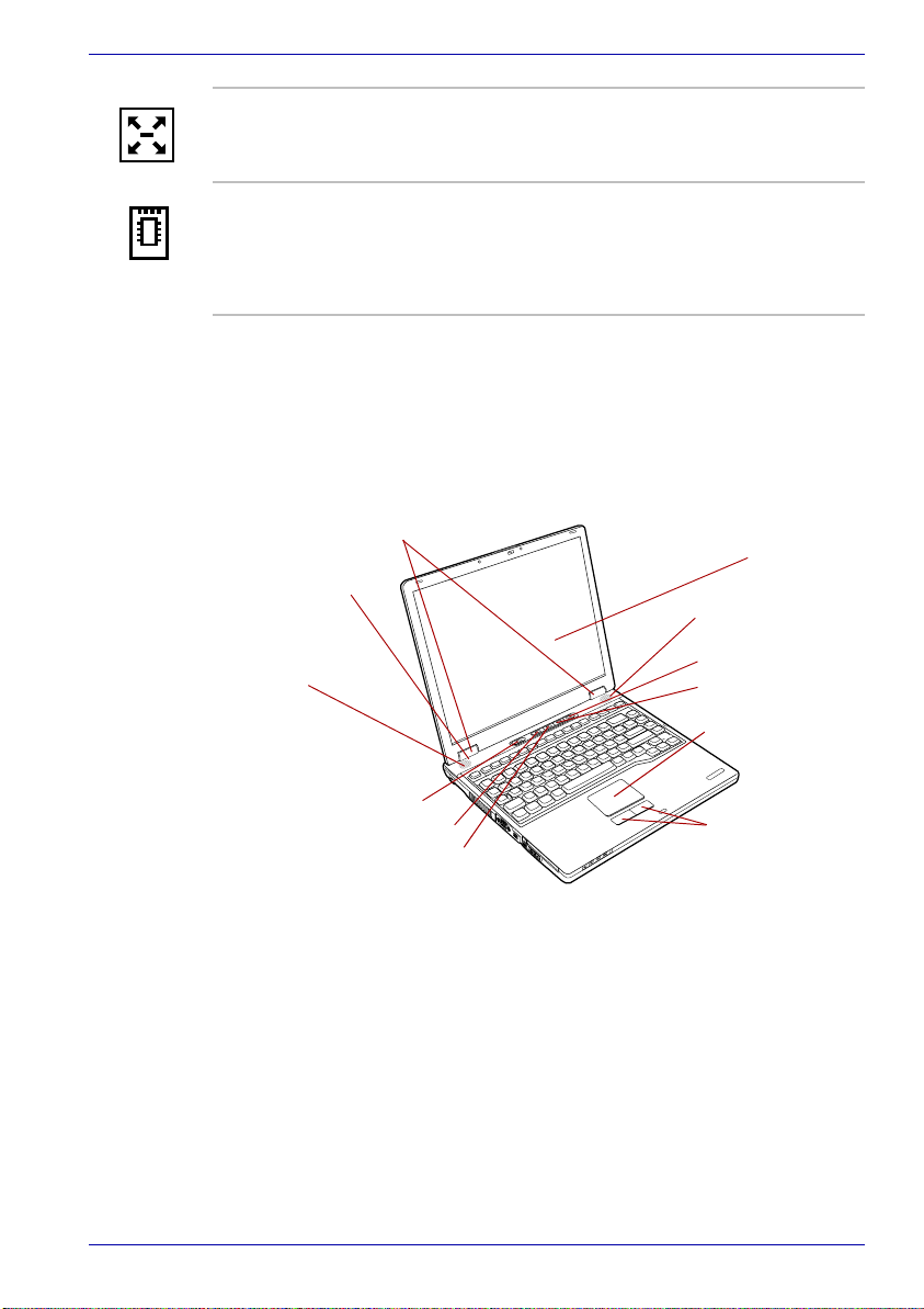
Front with the display open
This section shows the front of the computer with the display open. Refer to
the appropriate illustration for details. To open the display, slide the display
latch on the front of the display and lift up. Position the display at a
comfortable viewing angle.
Display hinge
LCD Sensor switch
(Not shown)
Stereo speaker
(Left)
Power button
TOSHIBA Console button
TOSHIBA Presentation button
Display screen
Stereo speaker
(Right)
Zoom in (+) button
Zoom out (-) button
Touch pad
Touch pad
control buttons
The front of the computer with the display open
User’s Manual 2-7

The Grand Tour
Display hinge The display hinge holds the display screen at
easy-to-view angles.
Display screen The LCD displays high-contrast text and
graphics. The computer’s LCD consists of up to
1024 × 768 pixels or 1400 × 1050 pixels. Refer to
Display Controller and Modes section in
Appendix B.
When the computer operates on the AC adaptor
the display screen’s image will be somewhat
brighter than when it operates on battery power.
The lower brightness level is intended to save
battery power.
Stereo speakers The speakers emit sound generated by your
software as well as audio alarms, such as low
battery condition, generated by the system.
Touch pad
control buttons
Control buttons below the Touch pad let you
select menu items or manipulate text and
graphics designated by the on-screen pointer.
Touch pad A Touch pad located in the center of the palm
rest is used to control the on-screen pointer.
Refer to the Using the Touch pad section in
Chapter 4, Operating Basics.
TOSHIBA
Presentation button
Press this button to change internal display,
simultaneous display, or multi-monitor display.
The default setting is the simultaneous display on
LCD and CRT with resolution of 1024 × 768.
When you press this button twice, the display
mode returns to single display on LCD only.
Setting of multi-monitor display in Windows XP,
PC changes its display mode to the multi-monitor
display on LCD and CRT. You can also return to
single display by pressing this button twice.
The setting of TOSHIBA Presentation button can
be changed through the property of TOSHIBA
Console. Display mode is changed to the multimonitor display by selecting "Different Image"
(Windows XP only) or to the simultaneous
display on internal and external display by
selecting "Same Image".
TOSHIBA Console
button
Press this button to launch an application
automatically.
The default is TOSHIBA Console.
User’s Manual 2-8

The Grand Tour
Zoom out (-) button *Zoom out (-) button is provided with some
models.
Press this button to reduce the icon size on the
desktop or the application window. Refer to the
Hot keys section in Chapter 5, The keyboard.
Zoom in (+) button *Zoom in (+) button is provided with some
models.
Press this button to enlarge the icon size on the
desktop or the application window. Refer to the
Hot keys section in Chapter 5, The keyboard.
Power button Press the power button to turn the computer’s
power on and off.
LCD Sensor switch This switch senses when the LCD panel is closed
or opened and activates the Panel Power Off/On
feature. When you close the panel the computer
enters Hibernation Mode and shuts down. When
you open the panel the computer starts in
Hibernation Mode. Use the TOSHIBA Power
Saver Utility to enable or disable this feature. The
default is “enabled”. Refer to the TOSHIBA
Power Saver Utility and Panel Power Off/On
items in Chapter 1, Introduction, for details on
settings.
Do not put a magnetic object close to the switch. The computer will
automatically enter Hibernation Mode and shut down even if the Panel
Power Off features is disabled.
User’s Manual 2-9

System indicators
DC IN 15V Power Battery Built-in HDD
DC IN 15V The DC IN 15V indicator glows green when DC
The Grand Tour
System indicators
power is supplied from the AC power adaptor. If
the adaptor’s output voltage is abnormal or if the
power supply malfunctions, this indicator flashes
orange.
Power The Power indicator glows green when the
Battery The Battery indicator shows the condition of the
Built-in HDD The Built-in HDD indicator glows green when
computer is on. If you select Standby from Shut
Down Windows, this indicator flashes orange
(one second on, two seconds off) while the
computer shuts down.
battery’s charge: Green indicates full charge,
orange indicates battery charging and flashing
orange indicates a low battery charge. Refer to
Chapter 6, Power and Power-Up Modes.
the computer is accessing the hard disk.
User’s Manual 2-10

Keyboard indicators
The figures below show the positions of the keypad overlay indicators and
the Caps Lock indicator.
When the F10 key indicator glows the keypad overlay lets you control the
cursor.
When the F11 key indicator glows the keypad overlay lets you enter
numbers.
Arrow Mode
indicator
When the Caps Lock indicator glows the keyboard is in all-caps mode.
Keypad overlay indicators
The Grand Tour
Numeric Mode
indicator
Caps Lock
indicator
Caps Lock indicator
Caps Lock This indicator glows green when the alphabet
keys are locked in uppercase.
Arrow mode When the Arrow mode indicator lights green,
you can use the keypad overlay (gray labeled
keys) as cursor keys. Refer to the Keypad
overlay section in Chapter 5, The Keyboard.
Numeric mode You can use the keypad overlay (gray labeled
keys) for numeric input when the Numeric mode
indicator lights green. Refer to the Keypad
overlay section in Chapter 5, The Keyboard.
User’s Manual 2-11

USB floppy disk drive (optional)
An optional 3 1/2" floppy disk drive accommodates 1.44-megabyte or 720kilobyte floppy disks. It connects to the USB port.
The Grand Tour
Disk-In-Use
Indicator
Disk-In-Use
Indicator
Floppy disk
slot
USB floppy disk drive
Eject button
This indicator lights when the floppy disk is being
accessed.
Floppy disk slot Insert a floppy disk in this slot.
Eject button When a floppy disk is fully seated in the drive, the
eject button pops out. To remove a floppy disk,
push in the eject button and the floppy disk pops
out partially for removal.
Check the Disk-In-Use indicator when you use the floppy disk drive. Do
not press the eject button or turn off the computer while the light is glowing.
Doing so could destroy data and damage the floppy disk or the drive.
■ The external floppy disk drive should be placed on a flat, horizontal
surface when in use. Do not set the drive on an incline greater than 20
while it is operating.
■ Do not set anything on top of the floppy disk drive.
o
User’s Manual 2-12

Fixed optical media drives
One of the following optical media drives is installed in the computer: DVDROM, DVD-ROM&CD-R/RW, DVD-R/-RW, DVD Super Multi drives. An
ATAPI interface controller is used for CD/DVD-ROM operation. When the
computer is accessing a CD/DVD, an indicator on the drive glows.
Region codes for DVD drives and media
CD-ROM, DVD-ROM, DVD-ROM&CD-R/RW, DVD-R/-RW, DVD Super
Multi drives and media are manufactured according to the specifications of
six marketing regions. When you purchase DVD-Video, make sure it
matches your drive, otherwise it will not play properly.
.
Code Region
1 Canada, United States
2 Japan, Europe, South Africa, Middle East
3 Southeast Asia, East Asia
4 Australia, New Zealand, Pacific Islands, Central
America, South America, Caribbean
5 Russia, Indian Subcontinent, Africa, North Korea,
Mongolia
The Grand Tour
6 China
Writable discs
This section describes the types of writable CD/DVD discs. Check the
specifications for your drive for the type of discs it can write. Use
RecordNow! to write compact discs. Refer to Chapter 4, Operating Basics.
CDs
■ CD-R discs can be written only once. The recorded data cannot be
erased or changed.
■ CD-RW discs can be recorded more than once. Use either 1, 2, or 4
multi speed CD-RW discs or high-speed 4- to 10-speed discs. The write
speed of the ultra-speed CD-RW discs (Ultra-speed is DVD-ROM&CDR/RW drive only) is maximum 24-speed.
User’s Manual 2-13

DVDs
■ DVD-R discs can be written only once. The recorded data cannot be
erased or changed.
■ DVD-RW discs can be recorded more than once.
■ DVD-RAM discs can be recorded more than once.
■ DVD+R discs can be written only once. The recorded data cannot be
erased or changed.
■ DVD+RW discs can be recorded more than once.
Formats
The drives support the following formats:
■ DVD-ROM
■ CD-DA
TM
■ Photo CD
■ CD-ROM XA Mode 2 (Form1,
Form2)
■ CD-G (Audio CD only)
(single/multi-session)
■ DVD-Video
■ CD-Text
■ CD-ROM Mode 1, Mode 2
■ Enhanced CD (CD-EXTRA)
■ Addressing Method 2
DVD-ROM drive
The full-size DVD-ROM drive module lets you run either 12 cm (4.72") or 8
cm (3.15") CD/DVDs without using an adaptor.
The Grand Tour
The read speed is slower at the center of a disc and faster at the outer
edge.
DVD read 8 speed (maximum)
CD read 24 speed (maximum)
DVD-ROM&CD-R/RW drive
The full-size DVD-ROM&CD-R/RW drive module lets you record data to
rewritable CDs as well as run either 12 cm (4.72") or 8 cm (3.15") CD/DVDs
without using an adaptor.
The read speed is slower at the center of a disc and faster at the outer
edge.
DVD read 8 speed (maximum)
CD read 24 speed (maximum)
CD-R write 24 speed (maximum)
CD-RW write 24 speed (maximum, Ultra speed media)
User’s Manual 2-14

DVD-R/-RW drive
The full- size DVD-R/-RW drive module lets you record data to rewritable
CD/DVDs as well as run either 12 cm (4.72") or 8 cm (3.15") CD/DVDs
without using an adaptor.
The read speed is slower at the center of a disc and faster at the outer
edge.
DVD read 8 speed (maximum)
DVD-R write 2 speed
DVD-RW write 1 speed
CD read 24 speed (maximum)
CD-R write 16 speed (maximum)
CD-RW write 10 speed (maximum, high-speed media)
DVD Super Multi drive
The full-size DVD Super Multi drive module lets you record data to
rewritable CD/DVDs as well as run either 12 cm (4.72") or 8 cm (3.15") CD/
DVDs without using an adaptor.
The read speed is slower at the center of a disc and faster at the outer
edge.
DVD read 8 speed (maximum)
DVD-R write 4 speed (maximum)
DVD-RW write 2 speed (maximum)
DVD+R write 2.4 speed (maximum)
DVD+RW write 2.4 speed (maximum)
DVD-RAM write 2 speed (maximum)
CD read 24 speed (maximum)
CD-R write 16 speed (maximum)
CD-RW write 8 speed (maximum, high-speed media)
The Grand Tour
User’s Manual 2-15

AC adaptor
The AC adaptor converts AC power to DC power and reduces the voltage
supplied to the computer. It can automatically adjust to any voltage from
100 to 240 volts and to a frequency of either 50 or 60 hertz, enabling you to
use the computer in almost any country/region.
To recharge the battery, simply connect the AC adaptor to a power source
and the computer. Refer to Chapter 6 Power and Power-Up Modes for
details.
■ Use only the AC adaptor that came with the computer or an equivalent
■ Use only the AC Adapter supplied with your computer or an equivalent
The Grand Tour
The AC adaptor
optional adaptor. Use of the wrong adaptor could damage your
computer. TOSHIBA assumes no liability for any damage in such case.
adapter that is compatible. Use of any incompatible adapter or other
types of AC Adapters may have a different voltage which could cause
damage to your computer, computer failure and/or possible data loss.
Toshiba assumes no liability for any damage, computer failure and/or
data loss caused by use of an incompatible adapter.
Use only the AC adaptor supplied as an accessory. Other AC adaptors
have different voltage and terminal polarities and use of them may produce
heat and smoke or even result in fire or rupture.
User’s Manual 2-16

TECRA A2
Getting Started
This chapter provides basic information to get you started using your
computer. It covers the following topics:
■ Setting up your work space — for your health and safety
Be sure also to read the Safety Instruction Manual. This guide, which is
included with the computer, explains product liability.
■ Installing the battery pack
■ Connecting the AC adaptor
■ Opening the display
■ Turning on the power
■ Windows XP setup
■ Turning off the power
■ Restarting the computer
■ Creating recovery media
■ Restoring the preinstalled software from the HDD
■ Restoring the preinstalled software from the Recovery Media
Chapter 3
All users should be sure to read the section Windows XP setup.
Setting up your work space
Establishing a comfortable work site is important for you and your
computer. A poor work environment or stressful work habits can result in
discomfort or serious injury from repetitive strain to your hands, wrists or
other joints. Proper ambient conditions should also be maintained for the
computer’s operation. This section discusses the following topics:
■ General conditions
■ Placement of the computer
■ Seating and posture
■ Lighting
■ Work habits
User’s Manual 3-1

General conditions
In general, if you are comfortable, so is your computer, but read the
following to make sure your work site provides a proper environment.
■ Make sure there is adequate space around the computer for proper
ventilation.
■ Make sure the AC power cord connects to an outlet that is close to the
computer and easily accessible.
■ The temperature should be 5 to 35 degrees Centigrade (41 to 95
degrees Fahrenheit) and the relative humidity should be 20 to 80
percent.
■ Avoid areas where rapid or extreme changes in temperature or humidity
may occur.
■ Keep the computer free of dust, moisture, and exposure to direct
sunlight.
■ Keep the computer away from heat sources, such as electric heaters.
■ Do not use the computer near liquids or corrosive chemicals.
■ Do not place the computer near objects that create strong magnetic
fields (e.g., stereo speakers).
■ Some components in the computer, including data storage media, can
be damaged by magnets. Do not place the computer near magnetic
objects or bring magnetic objects close to the computer. Be careful of
objects, such as stereo speakers, that produce strong magnetic fields
during operation. Also, be careful with metal objects, such as bracelets,
which can be inadvertently magnetized.
■ Do not operate the computer in close proximity to a mobile phone.
■ Leave ample ventilation room for the fan. Do not block the vents.
Getting Started
Placement of the computer
Position the computer and peripheral devices to provide comfort and safety.
■ Set the computer on a flat surface at a comfortable height and distance.
The display should be no higher than eye level to avoid eyestrain.
■ Place the computer so that it is directly in front of you when you work
and make sure you have adequate space to easily operate other
devices.
■ Allow adequate space behind the computer to let you freely adjust the
display. The display should be angled to reduce glare and maximize
visibility.
■ If you use a paper holder, set it at about the same height and distance
as the computer.
User’s Manual 3-2

Seating and posture
The height of your chair in relation to the computer and keyboard as well as
the support it gives your body are primary factors in reducing work strain.
Refer to the following tips to the figure below.
Below eye
level
90°angles
Foot rest
Posture and positioning of the computer
■ Place your chair so that the keyboard is at or slightly below the level of
your elbow. You should be able to type comfortably with your shoulders
relaxed.
■ Your knees should be slightly higher than your hips. If necessary, use a
foot rest to raise the level of your knees to ease pressure on the back of
your thighs.
■ Adjust the back of your chair so it supports the lower curve of your
spine.
■ Sit straight so that your knees, hips and elbows form approximately 90
degree angles when you work. Do not slump forward or lean back too
far.
Getting Started
Lighting
Proper lighting can improve legibility of the display and reduce eyestrain.
■ Position the computer so that sunlight or bright indoor lighting does not
reflect off the screen. Use tinted windows, shades or other screen to
eliminate sun glare.
■ Avoid placing the computer in front of bright light that could shine
directly in your eyes.
■ If possible, use soft, indirect lighting in your computer work area. Use a
lamp to illuminate your documents or desk, but be sure to position the
lamp so that it does not reflect off the display or shine in your eyes.
User’s Manual 3-3

Work habits
A key to avoiding discomfort or injury from repetitive strain is to vary your
activities. If possible, schedule a variety of tasks into your workday. If you
must spend long periods at the computer, finding ways to break up the
routine can reduce stress and improve your efficiency.
■ Sit in a relaxed posture. Good positioning of your chair and equipment
as described earlier can reduce tension in your shoulders or neck and
ease back strain.
■ Vary your posture frequently.
■ Occasionally stand up and stretch or exercise briefly.
■ Exercise and stretch your wrists and hands a number of times during
the day.
■ Frequently, look away from the computer and focus your eyes on a
distant object for several seconds, for example 30 seconds every 15
minutes.
■ Take frequent short breaks instead of one or two long breaks, for
example, two or three minutes every half hour.
■ Have your eyes examined regularly and visit a doctor promptly, if you
suspect you might be suffering from a repetitive strain injury.
A number of books are available on ergonomics and repetitive strain injury
or repetitive stress syndrome. For more information on these topics or for
pointers on exercises for such stress points as hands and wrists, please
check with your library or book vendor. Also refer to the computer’s Safety
Instruction Manual .
Getting Started
Installing the battery pack
To install a battery, follow the steps below.
■ The battery pack is a lithium ion battery, which can explode if not
properly replaced, used, handled or disposed of. Dispose of the battery
as required by local ordinances or regulations. Use only batteries
recommended by TOSHIBA as replacements.
■ Do not touch the latch while holding the computer. Or you may get
injured by the dropped battery by unintentional release of the latch.
■ Please do not push the power button before installing the battery pack.
1. Turn the computer’s power off.
2. Disconnect all cables connected to the computer.
3. Insert the battery pack.
User’s Manual 3-4

Getting Started
4. Secure the battery pack release latch(1). Check the battery lock was
changed to the lock position.
Battery release
latch(1)
Securing the battery pack
Battery pack
Refer to Removing the battery pack section in Chapter 6, Power and
Power-Up Modes for removing the battery pack.
Connecting the AC adaptor
Attach the AC adaptor when you need to charge the battery or you want to
operate from AC power. It is also the fastest way to get started, because
the battery pack will need to be charged before you can operate from
battery power.
The AC adaptor can be connected to any power source supplying from 100
to 240 volts and 50 or 60 hertz. For details on using the AC adaptor to
charge the battery pack, refer to Chapter 6, Power and Power-Up Modes.
Use only the AC adaptor supplied as an accessory. Other AC adaptors
have different voltage and terminal polarities and use of them may produce
heat and smoke or even result in fire or rupture.
User’s Manual 3-5
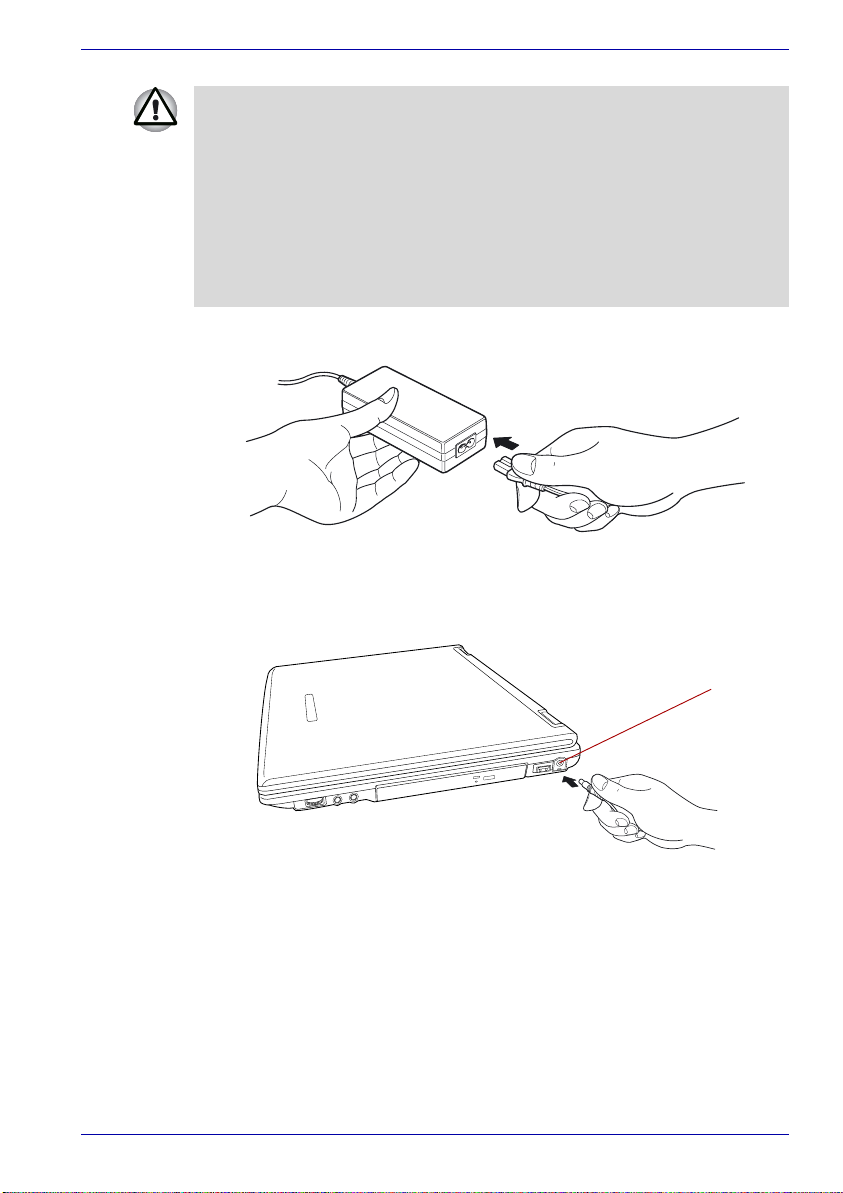
Getting Started
■ Use only the AC adaptor supplied with your computer or an equivalent
adaptor that is compatible. Use of any incompatible adaptor could
damage your computer. TOSHIBA assumes no liability for any damage
caused by use of an incompatible adaptor.
■ When you connect the AC adaptor to the computer, always follow the
steps in the exact order as described in the User’s Manual. Connecting
the power cable to a live electrical outlet should be the last step
otherwise the adaptor DC output plug could hold an electrical change
and cause an electrical shock or minor bodily injury when touched. As
a general safety precaution, avoid touching any metal parts.
1. Connect the power cord to the AC adaptor.
Connecting the power cord to the AC adaptor
2. Connect the AC adaptor’s DC output plug to the DC IN 15V jack on the
right side of the computer.
DC IN 15V jack
Connecting the adaptor to the computer
3. Plug the power cord into a live wall outlet. The Battery and DC IN 15V
indicators on the front of the computer should glow.
Opening the display
The display panel can be rotated in a wide range of angles for optimal
viewing.
1. Slide the display latch on the front of the computer to the right.
User’s Manual 3-6

2. While holding down the palm rest with one hand so that the main body
is not raised, lift the panel slowly. Adjust the angle of the panel to
provide optimal clarity.
Use reasonable care when opening and closing the display panel. Opening
it vigorously or slamming it shut could damage the computer.
Turning on the power
This section describes how to turn on the power.
Getting Started
Display latch
Opening the display
After you turn on the power for the first time, do not turn it off until you have
set up the operating system. Refer to the section Windows XP setup.
1. If an optional external floppy disk drive is connected, make sure it is
empty. If a floppy disk is in the drive, press the eject button and remove
the floppy disk.
2. Open the display.
3. Press and hold the computer’s power button for two or three seconds.
Power button
Turning on the power
User’s Manual 3-7

Windows XP setup
When you first turn on the power, the computer’s initial screen is the
Microsoft Windows XP Professional Startup Screen Logo.
Follow the on-screen directions.
Turning off the power
The power can be turned off in one of the following modes: Shut down
(Boot), Hibernation or Standby Mode.
Shut Down mode (Boot mode)
When you turn off the power in Shut Down mode no data is saved and the
computer will boot to the operating system’s main screen.
1. If you have entered data, save it to the hard disk or to a diskette.
2. Make sure all disk (disc) activity has stopped, then remove the CD/
DVDs or diskette.
Make sure the Built-in HDD and CD/DVD-in-use indicators are off. If you
turn off the power while a disk (disc) is being accessed, you can lose data
or damage the disk (disc).
3. Click start then click Turn Off Computer. From the Turn Off
Computer menu select Tur n Off .
4. Turn off the power to any peripheral devices.
Getting Started
Do not turn the computer or devices back on immediately. Wait a moment
to let all capacitors fully discharge.
Hibernation Mode
The hibernation feature saves the contents of memory to the hard disk
when the computer is turned off. The next time the computer is turned on,
the previous state is restored. The hibernation feature does not save the
status of peripheral devices.
■ Save your data. While entering Hibernation Mode, the computer saves
the contents of memory to the HDD. However, for safety sake, it is best
to save your data manually.
■ Data will be lost if you remove the battery or disconnect the AC adaptor
before the save is completed. Wait for the Disk indicator to go out.
■ Do not install or remove a memory module while the computer is in
Hibernation Mode. Data will be lost.
Benefits of hibernation
The hibernation feature provides the following benefits:
■ Saves data to the hard disk when the computer automatically shuts
down because of a low battery.
User’s Manual 3-8

Getting Started
For the computer to shut down in Hibernation Mode, the hibernation
feature must be enabled in two places: the Hibernate tab in Power Options
and Setup Action tab in TOSHIBA Power Saver.
Otherwise, the computer will shut down in Standby Mode. If battery power
becomes depleted, data saved in Standby Mode will be lost.
■ You can return to your previous working environment immediately when
you turn on the computer.
■ Saves power by shutting down the system when the computer receives
no input or hardware access for the duration set by the System
hibernate feature.
■ You can use the panel power off feature.
Starting Hibernation
You can also enable Hibernation by pressing Fn + F4. Refer to Chapter 5,
The Keyboard, for details.
To enter Hibernation Mode, follow the steps below.
1. Click start.
2. Select Turn Off Computer.
3. Open the Turn Off Computer dialog box. Hibernate is not displayed.
4. Press the Shift key. The Standby item will change to Hibernate.
5. Select Hibernate.
Automatic Hibernation
The computer will enter Hibernate Mode automatically when you press the
power button or close the lid. First, however, make the appropriate settings
according to the steps below.
1. Open the Control Panel.
2. Open Performance and Maintenance and open Power Options.
3. Select the Hibernate window in the Power Options Properties,
select the Enable hibernation check box and click the Apply button.
4. Open TOSHIBA Power Saver.
5. Select the Setup Action window.
6. Enable the desired Hibernation settings for When I slide the power
button and When I close the lid.
7. Click the OK button.
Data save in Hibernation Mode
When you turn off the power in Hibernation Mode, the computer takes a
moment to save current memory data to the hard disk. During this time, the
Disk indicator will light.
After you turn off the computer and memory is saved to the hard disk, turn
off the power to any peripheral devices.
User’s Manual 3-9

Do not turn the computer or devices back on immediately. Wait a moment
to let all capacitors fully discharge.
Standby Mode
If you have to interrupt your work, you can turn off the power without exiting
from your software. Data is maintained in the computer’s main memory.
When you turn on the power again, you can continue working right where
you left off.
■ When the AC adaptor is connected, the computer will go into Standby
Mode according to the settings in the TOSHIBA Power Saver utility.
■ To restore operation from Standby Mode, press the power button or
press any key. The latter action works only if Wake-up on Keyboard is
enabled in HW Setup.
■ If the computer automatically enters Standby Mode while a network
application is active, the application might not be restored when the
computer wakes up from Standby.
■ To prevent the computer from automatically entering Standby Mode,
disable Standby in TOSHIBA Power Saver. That action, however, will
nullify the computer’s Energy Star compliance.
■ Before entering Standby Mode, be sure to save your data.
■ Do not install or remove a memory module while the computer is in
Standby Mode. The computer or the module could be damaged.
■ Do not remove the battery pack while the computer is in Standby Mode
(unless the computer is connected to an AC power source). Data in
memory will be lost.
■ If you carry the computer on board an aircraft or into a hospital, be sure
to shut down the computer in Hibernation Mode or in shutdown mode
to avoid radio signal interference.
Getting Started
Benefits of Standby
The standby feature provides the following benefits:
■ Restores the previous working environment more rapidly than does
hibernation.
■ Saves power by shutting down the system when the computer receives
no input or hardware access for the duration set by the System Standby
feature.
■ You can use the panel power off feature.
User’s Manual 3-10

Getting Started
Executing Standby
You can also enable Standby by pressing Fn + F3. Refer to Chapter 5, The
Keyboard, for details.
You can enter Standby Mode in one of three ways:
1. Click Start, click Turn Off Computer and click Stand by.
2. Close the display panel. This feature must be enabled. Refer to the
Setup Action tab in TOSHIBA Power Saver Utility described in the
Control Panel.
Open Performance and Maintenance and open TOSHIBA Power
Saver.
3. Press the power button. This feature must be enabled. Refer to the
Setup Action tab in TOSHIBA Power Saver Utility described in the
Control Panel.
When you turn the power back on, you can continue where you left when
you shut down the computer.
■ When the computer is shut down in Standby Mode, the power indicator
flashes orange.
■ If you are operating the computer on battery power, you can lengthen
the operating time by shutting down in Hibernation Mode. Standby
Mode consumes more power.
Standby limitations
Standby will not function under the following conditions:
■ Power is turned back on immediately after shutting down.
■ Memory circuits are exposed to static electricity or electrical noise.
Restarting the computer
Certain conditions require that you reset the system. For example, if:
■ You change certain computer settings.
■ An error occurs and the computer does not respond to your keyboard
commands.
■ There are three ways to reset the computer system:
1. Click start then click Turn off computer. From the Turn off
computer menu select Restart.
2. Press Ctrl + Alt + Del to display the Windows Task Manager, then
select Shutdown and Restart.
3. Press the power button and hold it down for five seconds. Wait 10 to 15
seconds, then turn the power on again by pressing the power button.
User’s Manual 3-11

Restoring preinstalled software
Some models are prepared for Hard Disk Recovery. These models will
come without a Product Recovery optical media and a Tools & Utilities CD
ROM. You can restore the preinstalled software depending on the model
you purchased.
Restoring from the Product Recovery Media
For models only with a bundled Product Recovery optical media.
If preinstalled files are damaged, use the Product Recovery disk or the
TOSHIBA Tools & Utilities CD-ROM to restore them.
Restoring the complete system
To restore the operating system and all preinstalled software, follow the
steps below.
When you reinstall the Windows operating system, the hard disk will be
reformatted and all data will be lost. Make sure you have a backup copy of
your data, before you perform a complete system recovery.
1. Load the Product Recovery disk in the optical media drive and turn off
the computer’s power.
2. Hold down the F12 key and turn on the power. When In Touch with
Tomorrow TOSHIBA appears, release the F12 key.
3. Use the left or right cursor key to select the CD-ROM/DVD-ROM icon in
the display menu. For details, refer to the Boot Priority section in
Chapter 7, HW Setup and Passwords.
4. Follow the on-screen instructions.
5. If your computer came with additonal software installed, this software
can not be recovered from the Product Recovery disk. Re-install these
applications (e.g. Works Suite, DVD Player, Games, etc.) separately
from other media.
Getting Started
Restoring TOSHIBA utilities and drivers
If Windows is working properly, individual drivers or applications can be
separately restored. Use the Tools & Utilities CD-ROM according to
instructions in the booklet contained in the CD box to reinstall TOSHIBA
utilities and drivers.
User’s Manual 3-12

Restoring from Recovery HDD
For models only with Recovery HDD installed.
If preinstalled files are damaged, use the Recovery HDD installation to
restore them.
When you reinstall the Windows operating system, the hard disk will be
reformatted and all data will be lost. Make sure you have a backup copy of
your data, before you perform a complete system recovery.
Create Optical Recovery Discs
A recovery image of your computer is stored on the hard disk. You may use
this image to create CD or DVD recovery discs using the following steps:
1. Select either blank CDs or DVD media.
2. The Recovery Disc Creator Launcher application will allow you to
choose a type of media to create recovery CDs/DVD including: CD-R,
CD-RW, DVD-R, DVD-RW, DVD+R and DVD+RW.
Some media may not be compatible with the Optical Drive of your
computer. Please verify your Optical Drive supports the blank media you
choose.
Getting Started
3. Turn on your computer to open Windows XP.
4. Insert the (first) blank media into the tray of the Optical Drive.
5. Double click the Recovery Disc Creator Launcher icon on the Windows
XP desktop, or Select the application from Start Menu.
6. After Recovery Disc Creator starts, select the type of media and the title
you wish to copy to the media then click the Burn button.
If your Optical Drive can only write to CDs, select "CD" as the "Type" on
Recovery Disc Creator. If your Optical Drive of your computer can write to
either CD or DVDs, select the one you are using as the "Type" on
Recovery Disc Creator.
User’s Manual 3-13

Getting Started
Restoring the preinstalled software from the Recovery HDD
.
About 2GB of hard disk space is reserved for recovery partition.
When re-setting up your hard disk, do not change, delete or add partitions.
Otherwise, parts of the Recovery HDD or operating system may be
destroyed.
In addition, if you use a third-party partitioning program to reconfigure
partitions on your hard disk, it may become impossible to re-setup your
computer.
1. Turn off your computer.
2. While holding down “0” (zero) key on the keyboard, turn on your
computer.
3. A menu appears. Press the "1" key on the keyboad to restore the
original configration as purchased. Press the "2" key to keep your
current partitions intact and restore. Press the "3" key to specify
partitions and restore.
4. Follow the on-screen instructions.
Restoring the preinstalled software from your created
Recovery Media
If preinstalled files are damaged, use your created Recovery Media or
Recovery HDD to restore them. To restore the operating system and all
preinstalled software, follow the steps below.
When you reinstall the Windows operating system, the hard disk will be
reformatted and all data will be lost.
1. Load the Recovery Media in the optical media drive and turn off the
computer's power.
2. Hold down the F12 key and turn on the power. When In Touch with
Tomorrow TOSHIBA appears, release the F12 key.
3. Use the left or right cursor key to select the CD-ROM icon in the display
menu. For details, refer to the Boot Priority section in Chapter 7, HW
Setup and Passwords.
4. A menu appears. Press the "1" key on the keyboard to restore all hard
disk. Press the "2" key to Restore drive C:. Press the "3" key to restore
the Recovery HDD partition.
5. Follow the on-screen instructions.
User’s Manual 3-14

TECRA A2
Operating Basics
This chapter gives information on basic operations including using the
Touch pad, the optional USB floppy disk drive, optical media drives, Sound
System, modem, the wireless communication and LAN. It also provides tips
on caring for your computer and on heat dispersal.
Using the Touch pad
To use the Touch pad, simply touch and move your finger tip across it in the
direction you want the on-screen pointer to go.
Chapter 4
Touch pad
Touch pad control buttons
Touch pad and Touch pad control buttons
Two buttons below the keyboard are used like the buttons on a mouse
pointer. Press the left button to select a menu item or to manipulate text or
graphics designated by the pointer. Press the right button to display a menu
or other function depending on the software you are using.
Do not press on the Touch pad too hard or press a sharp object such as a
ball point pen against the Touch pad. The Touch pad could be damaged.
For some functions, you can tap the Touch pad instead of pressing a
control button.
User’s Manual 4-1

Click: Tap the Touch pad once
Double-click: Tap the Touch pad twice
Drag and drop:
1. Hold down the left control button and move the cursor to drag the item
you want to move.
2. Lift your finger to drop the item where you want it.
Scroll:
Vertical: Move your finger up or down the right edge of the Touch pad.
Horizontal: Move your finger left or right along the bottom edge of the
Touch pad.
Using the USB floppy disk drive (optional)
An optional 3 1/2" floppy disk drive connects to the computer’s USB port. It
accommodates 1.44-megabyte or 720-kilobyte floppy disks. Refer to
Chapter 2, The Grand Tour, for more information.
Connecting 3 1/2" floppy disk drive
To connect the drive, plug the floppy disk drive connector into a USB port.
Refer to the figure below.
Make sure the connector is right side up and properly aligned with the
socket. Do not try to force the connection; doing so can damage the
connecting pins.
Operating Basics
Connecting the USB floppy disk drive
If you connect the floppy disk drive after turning on the computer, it will take
about 10 seconds for the computer to recognize the drive. Do not
disconnect and reconnect before 10 seconds has elapsed.
User’s Manual 4-2

Disconnecting 3 1/2" floppy disk drive
When you have finished using the floppy disk drive, follow the procedures
below to disconnect it:
1. Wait for the indicator light to go out to make sure all floppy disk activity
has stopped.
If you disconnect the floppy disk drive or turn off the power while the
computer is accessing the drive you may lose data or damage the floppy
disk or the drive.
2. Click the Safety Remove Hardware icon on the Task Bar.
3. Click floppy disk drive.
4. Pull the floppy disk drive connector out of the USB port.
Using optical media drives
The text and illustrations in this section refer primarily to the optical DVDROM drive. However, operation is the same for all other optical media
drives. The full-size drive provides high-performance execution of CD/
DVD-ROM-based programs. You can run either 12 cm (4.72") or 8 cm
(3.15") CD/DVDs without an adaptor. An ATAPI interface controller is used
for CD/DVD-ROM operation. When the computer is accessing a CD/DVDROM, an indicator on the drive glows.
Use the WinDVD 5 application to view DVD-Video discs.
Operating Basics
If you have a DVD-ROM&CD-R/RW drive, refer also to the Writing CDs on
DVD-ROM&CD-R/RW drive section for precautions on writing to CDs.
If you have a DVD-R/-RW drive, refer also to the Writing CD/DVDs on
DVD-R/-RW drive section for precautions on writing to CD/DVDs.
If you have a DVD Super Multi drive, refer also to the Writing CD/DVDs on
DVD Super Multi drive section for precautions on writing to CD/DVDs.
User’s Manual 4-3

Loading discs
To load CD/DVDs, follow the steps below and refer to the figures.
1. a. When the power is on, press the DVD-ROM eject button to open
the drawer slightly.
Eject button
Pressing the DVD-ROM eject button
b. Pressing the eject button will not open the drawer when the DVD-
ROM drive’s power is off. If the power is off, you can open the
drawer by inserting a slender object (about 15 mm) such as a
straightened paper clip into the eject hole just to the right of the
eject button.
Operating Basics
15mm
Diameter 1.0mm
Manual release with the eject hole
2. Grasp the drawer gently and pull until it is fully opened.
Pulling the drawer open
User’s Manual 4-4

Operating Basics
3. Lay the CD/DVD, label side up, in the drawer.
Inserting a CD/DVD
When the drawer is fully opened, the edge of the computer will extend
slightly over the CD/DVD tray. Therefore, you will need to turn the CD/DVD
at an angle when you place it in the tray. After seating the CD/DVD,
however, make sure it lies flat, as shown in figure above.
■ Do not touch the laser lens. Doing so could cause misalignment.
■ Keep foreign matter from entering the drive. Check the back edge of
the tray to make sure it carries no debris before closing the drive.
4. Press gently at the center of the CD/DVD until you feel it click into
place. The CD/DVD should lie below the top of the spindle, flush with
the spindle base.
5. Push the center of the drawer to close it. Press gently until it locks into
place.
If the CD/DVD is not seated properly when the drawer is closed, the CD/
DVD might be damaged. Also, the drawer might not open fully when you
press the eject button.
Closing the DVD-ROM drawer
User’s Manual 4-5

Removing discs
To remove the CD/DVD, follow the steps below and refer to figure below.
Do not press the eject button while the computer is accessing the DVDROM drive. Wait for the optical media drive indicator to go out before you
open the drawer. Also, if the CD/DVD is spinning when you open the
drawer, wait for it to stop before you remove it.
1. To pop the drawer partially open, press the eject button. Gently pull the
drawer out until it is fully opened.
■ When the drawer pops open slightly, wait a moment to make sure the
CD/DVD has stopped spinning before pulling the drawer fully open.
■ Turn off the power before you use the eject hole. If the CD/DVD is
spinning when you open the drawer, the CD/DVD could fly off the
spindle and cause injury.
2. The CD/DVD extends slightly over the sides of the drawer so you can
hold it. Hold the CD/DVD gently and lift it out.
Operating Basics
Removing a CD/DVD
3. Push the center of the drawer to close it. Press gently until it locks into
place.
User’s Manual 4-6

Writing CDs on DVD-ROM&CD-R/RW drive
Depending on the type of drive installed, you may be able to write CDs. The
DVD-ROM&CD-R/RW drive lets you write as well as read CD-ROMs.
Observe the precautions in this section to ensure the best performance for
writing CDs. For information on loading and unloading CDs refer to the
Using optical media drive section.
CD-R discs can be written to only once. CD-RW discs can be rewritten
many times.
Before writing or rewriting
Please observe the following points when you write or rewrite the data.
■ We recommend the following manufacturers of CD-R and CD-RW
media. Media quality can affect write or rewrite success rates.
CD-R: TAIYO YUDEN CO., LTD.
Mitsui Chemicals Inc.
MITSUBISHI CHEMICAL CORPORATION
RICOH Co., Ltd.
Hitachi Maxell Ltd.
CD-RW: MITSUBISHI CHEMICAL CORPORATION
RICOH Co., Ltd.
*For the special media listed below, the following manufacturers are
recommended.
■ Multi-Speed and High-Speed CD-ROM:
MITSUBISHI CHEMICAL CORPORATION, RICOH Co., Ltd.
■ Ultra-Speed CD-ROM:
MITSUBISHI CHEMICAL CORPORATION
TOSHIBA has confirmed the operation of CD-R and CD-RW media of the
manufacturers above. Operation of other media cannot be guaranteed.
■ CD-RW can generally be rewritten about 1,000 times. However, the
actual number of rewrites is affected by the quality of the media and the
way it is used.
■ Be sure to connect the AC adaptor when you write or rewrite.
■ Be sure to close all other software programs except the writing
software.
■ Do not run software such as a screen saver which can put a heavy load
on the CPU.
■ Operate the computer at full power. Do not use power-saving features.
■ Do not write while virus check software is running. Wait for it to finish,
then disable virus detection programs including any software that
checks files automatically in the background.
■ Do not use hard disk utilities, including those intended to enhance HDD
access speed. They may cause unstable operation and damage data.
Operating Basics
User’s Manual 4-7

■ Write from the computer's HDD to the CD. Do not try to write from
shared devices such as a LAN server or any other network device.
■ Writing with software other than Sonic RecordNow! has not been
confirmed. Therefore, operation with other software cannot be
guaranteed.
When writing or rewriting
Note the following when you write or rewrite a CD-R or CD-RW.
■ Always copy data from the hard disk drive to the CD. Do not use cut-
and-paste. The original data will be lost if there is a write error.
■ Do not perform any of the following actions:
■ Change users in the Windows XP operating system.
■ Operate the computer for any other function, including use of a
mouse or Touch pad, closing/opening the LCD panel.
■ Start a communication application such as a modem.
■ Apply impact or vibration to the PC.
■ Install, remove or connect external devices, including the following:
PC Card, USB devices, external display, optical digital devices.
■ Open the optical media drive.
■ If the media is poor in quality, dirty or damaged, writing or rewriting
errors may occur.
■ Set the computer on a level surface and avoid places subject to
vibration such as airplanes trains, or cars. Do not use an unstable
surface such as a stand.
■ Keep mobile phones and other wireless communication devices away
from the computer.
Operating Basics
Writing CD/DVDs on DVD-R/-RW drive
You can use the DVD-R/-RW drive to write data to either CD-R/-RW or
DVD-R/-RW discs. The following applications for writing are supplied on
CD-ROM:RecordNow!, licensed by Sonic Solutions.
InterVideo WinDVD Creator 2 Platinum, which is a product of InterVideo,
Inc.
Writing CD/DVDs on DVD Super Multi drive
You can use the DVD Super Multi drive to write data to either CD-R/RW or
DVD-R/-RW/+R/+RW/-RAM discs. The following applications for writing are
supplied on CD-ROM:RecordNow!, licensed by Sonic Solutions.
InterVideo WinDVD Creator 2 Platinum, which is a product of InterVideo,
Inc.
User’s Manual 4-8

Important message (DVD-R/-RW drive)
Before you write or rewrite to CD-R/RW or DVD-R/-RW discs, read and
follow all setup and operating instructions in this section. If you fail to do so,
the DVD-R/-RW drive may not function properly, and you may fail to write or
rewrite, lose data or incur other damage.
Important message (DVD Super Multi drive)
Before you write or rewrite to CD-R/RW or DVD-R/-RW/+R/+RW/-RAM
discs, read and follow all setup and operating instructions in this section. If
you fail to do so, the DVD Super Multi drive may not function properly, and
you may fail to write or rewrite, lose data or incur other damage.
Disclaimer (DVD-R/-RW drive)
TOSHIBA does not bear responsibility for the following:
■ Damage to any CD-R/RW or DVD-R/-RW disc that may be caused by
writing or rewriting with this product.
■ Any change or loss of the recorded contents of CD-R/RW or DVD-R/-
RW disc that may be caused by writing or rewriting with this product, or
for any business profit loss or business interruption that may be caused
by the change or loss of the recorded contents.
■ Damage that may be caused by using third party equipment or
software.Given the technological limitations of current optical disc
writing drives, you may experience unexpected writing or rewriting
errors due to disc quality or problems with hardware devices. Also, it is
a good idea to make two or more copies of important data, in case of
undesired change or loss of the recorded contents.
Operating Basics
Disclaimer (DVD Super Multi drive)
TOSHIBA does not bear responsibility for the following:
■ Damage to any CD-R/RW or DVD-R/-RW/+R/+RW/-RAM disc that may
be caused by writing or rewriting with this product.
■ Any change or loss of the recorded contents of CD-R/RW or DVD-R/-
RW/+R/+RW/-RAM disc that may be caused by writing or rewriting with
this product, or for any business profit loss or business interruption that
may be caused by the change or loss of the recorded contents.
■ Damage that may be caused by using third party equipment or
software. Given the technological limitations of current optical disc
writing drives, you may experience unexpected writing or rewriting
errors due to disc quality or problems with hardware devices. Also, it is
a good idea to make two or more copies of important data, in case of
undesired change or loss of the recorded contents.
User’s Manual 4-9

Before writing or rewriting
■ Based on TOSHIBA's limited compatibility testing, we suggest the
following manufacturers of CD-R/RW and DVD-R/+R/-RW/+RW/-RAM
disc. However, in no event does TOSHIBA guarantee the operation,
quality or performance of any disc. Disc quality can affect write or
rewrite success rates.
CD-R: TAIYO YUDEN CO., LTD.
Mitsui Chemicals Inc.
MITSUBISHI CHEMICAL CORPORATION
RICOH Co., Ltd.
Hitachi Maxell Ltd.
CD-RW:(High-Speed,
Multi-Speed)
DVD-R: DVD Specifications for Recordable Disc for
DVD+R:
DVD-RW: DVD Specifications for Rerecordable Disc for
DVD+RW:
DVD-RAM: DVD Specifications for DVD-RAM Disc for
MITSUBISHI CHEMICAL CORPORATION
RICOH Co., Ltd.
General Version 2.0
TAIYO YUDEN CO., LTD.
PIONEER VIDEO CORPORATION
Matsushita Electric Industrial Co., Ltd.
MITSUBISHI CHEMICAL CORPORATION
RICOH Co., Ltd.
Versi on 1.1
VICTOR COMPANY OF JAPAN.LIMITED
MITSUBISHI CHEMICAL CORPORATION
MITSUBISHI CHEMICAL CORPORATION
RICOH Co., Ltd.
Version 2.0 or Version 2.1
Matsushita Electric Industrial Co., Ltd.
Hitachi Maxell Ltd.
Operating Basics
This drive cannot use discs that allow writing of 8 speeds or more (DVD-R,
DVD+R ), or 4 speeds or more (DVD-RW, DVD+RW)
■ If the disc is poor in quality, dirty or damaged, writing or rewriting errors
may occur. Be careful to check the disc for dirt or damage before you
use it.
■ The actual number of rewrites to CD-RW, DVD-RW, DVD+RW or DVD-
RAM is affected by the quality of the disc and the way it is used.
■ There are two types of DVD-R discs: authoring and general use discs.
Do not use authoring discs. Only general use discs can be written to by
a computer drive.
■ You can use DVD-RAM discs that can be removed from a cartridge and
DVD-RAM discs designed without a cartridge. You cannot use a disc
with a 4.7 GB single-sided capacity or 9.4 GB double-sided capacity.
User’s Manual 4-10

Operating Basics
■ Other DVD-ROM drives for computers or other DVD players may not be
able to read DVD-R/-RW or DVD+R/+RW discs.
■ Data written to a CD-R/DVD-R/DVD+R disc cannot be deleted either in
whole or in part.
■ In writing to a DVD-R/-RW, DVD+R/+RW or DVD-RAM disc, some disc
space is required for file management, so you may not be able to write
the full capacity of the disc.
■ Since the disc is based on the DVD standard, it might be filled with
dummy data if the written data is less than about 1 GB. Even if you write
only a small amount of data, it might take time to fill in the dummy data.
■ DVD-RAM formatted by FAT32 cannot be read in Windows 2000
without DVD-RAM Driver Software.
■ When multiple drives that can write data to discs are connected, be
careful not to write to the wrong drive.
■ Be sure to connect the AC adaptor before you write or rewrite.
■ Before you enter Standby/Hibernation Mode, be sure to finish DVD-
RAM writing. Writing is finished if you can eject DVD-RAM media.
■ Be sure to close all other software programs except the writing
software.
■ Do not run software such as a screen saver, which can put a heavy load
on the CPU.
■ Operate the computer in the full-power mode. Do not use power-saving
features.
■ Do not write while virus check software is running. Wait for it to finish
and then disable virus detection programs including any software that
checks files automatically in the background.
■ Do not use hard disk utilities, including those intended to enhance HDD
access speed. They may cause unstable operation and data damage.
■ Write from the computer's hard disk drive to the CD/DVD. Do not try to
write from shared devices such as a LAN server or any other network
device.
■ Writing with software other than RecordNow! is not recommended.
When writing or rewriting
Please observe/consider the following when you write or rewrite to a CD-R/
-RW, DVD-R/-RW/-RAM or DVD+R/+RW disc.
■ Do not perform any of the following actions when writing or rewriting:
■ Change users in the Windows XP operating system.
■ Operate the computer for any other function, including using a
mouse or Touch pad or closing/opening the LCD panel.
■ Start a communication application such as a modem.
■ Apply impact or vibration to the computer.
■ Install, remove or connect external devices, including the following:
PC Card, USB devices, external display, optical digital devices.
User’s Manual 4-11

■
Open the DVD-ROM&CD-R/RW, DVD-R/-RW or DVD Super Multi
drive.
■ Do not use shut down/log off and Standby/Hibernation while writing or
rewriting.
■ Make sure writing or rewriting is completed before going into Standby/
Hibernation. Writing is completed if you can open the DVD-ROM&CDR/RW, DVD-R/-RW or DVD Super Multi drive tray.
■ Set the computer on a level surface and avoid places subject to
vibration such as airplanes, trains, or cars. Do not use an unstable
surface such as a stand.
■ Keep mobile phones and other wireless communication devices away
from the computer.
■ Always copy data from the hard disk drive to the DVD-RAM. Do not use
cut-and-paste. The original data will be lost if there is a write error.
RecordNow! Basic for TOSHIBA
Note the following limitations when you use RecordNow!:
■ DVD-Video cannot be created using RecordNow!.
■ DVD-Audio cannot be created using RecordNow!.
■ You cannot use RecordNow!'s “Audio CD for Car or Home CD Player”
function to record music to the DVD-R/-RW or DVD+R/+RW disc.
■ Do not use the “Exact Copy” function of RecordNow! to copy DVD-
Video and DVD-ROM with copyright protection.
■ DVD-RAM disc cannot be backed up with the “Exact Copy” function of
RecordNow!.
■ You cannot back up a CD-ROM or CD-R/RW to DVD-R/-RW or DVD+R/
+RW using the “Exact Copy” function of RecordNow!.
■ You cannot back up DVD-ROM, DVD-Video or DVD-R/-RW or DVD+R/
+RW to CD-R/RW using the “Exact Copy” function of RecordNow!.
■ RecordNow! cannot record in packet format.
■ You might not be able to use the “Exact Copy” function of RecordNow!
to back up a DVD-R/-RW or DVD+R/+RW disc that was made with
other software on a different DVD-R/-RW or DVD+R/+RW recorder.
■ If you add data to a DVD-R and DVD+R disc that you have already
recorded to, you might not be able to read the added data under some
circumstances. It cannot be read in 16-bit operating systems, such as
Windows 98SE and Windows ME. In Windows NT4, you will need
Service Pack 6 or later to read added data. In Windows 2000, you will
need Service Pack 2 or later to read it. Some DVD-ROM and DVDROM&CD-R/RW drives cannot read added data regardless of the
operating system.
■ RecordNow! does not support recording to DVD-RAM discs. To record
to a DVD-RAM, use Explorer or other utility.
Operating Basics
User’s Manual 4-12

■ When you back up a DVD disc, be sure the source drive supports
recording to DVD-R/-RW or DVD+R/+RW discs. If the source drive
does not support recording to DVD-R/-RW or DVD+R/+RW discs, it
might not be backed up correctly.
■ When you back up a DVD-R, DVD-RW, DVD+R or DVD+RW, be sure to
use the same type of disc.
■ You cannot partially delete any data written to a CD-RW, DVD-RW or
DVD+RW disc.
Data Verification
To verify that data is written or rewritten correctly, follow the steps below
before you write or rewrite a data CD/DVD.
1. Click the Options button( ) on the RecordNow! Console to open the
Options panels.
2. Select the Data in the left-side menu.
3. Mark the Verify data written to the disc after burning check box in the
Data Options.
4. Click the OK button.
DLA for TOSHIBA
Note the following limitations when you use DLA:
■ This software supports only rewritable discs (DVD+RW, DVD-RW, and
CD-RW). It does not support DVD+R, DVD-R, and CD-R discs that are
not rewritable.
■ DLA does not support formatting the DVD-RAM disc and writing to it.
They are performed by DVD-RAM Driver Software. The proper software
works according to the disc inserted in the drive.
■ Do not use any discs that have been formatted with packet writing
software other than DLA. Similarly, do not use any discs that have been
formatted with DLA with any packet writing software other than DLA.
When using a disc you are not familiar with, format it by selecting “Full
Format” before using it.
■ Do not use the Cut & Paste function for files and folders. A file or folder
that has been cut may be lost if writing fails due to an error on the disc.
Operating Basics
Video
As for InterVideo WinDVD Creater2 Platinum. Only the model that can be
written in to DVD is attached.
Note the following limitations when you write video to DVD:
■ When installing or uninstalling and using InterVideo WinDVD Creator 2
Platinum, the computer should be set to system administrator or
equivalent privilege.
User’s Manual 4-13

■ While you are editing DVD-R/-RW/+R/+RW/-RAM, you can display
previews. However, if an application other than WinDVD is running, the
preview might not display properly. To ensure proper display of
previews, do not start other applications while you are editing DVD-R/
-RW/+R/+RW/-RAM discs.
■ Do not change the resolution or the number of screen colors while
InterVideo WinDVD Creator 2 Platinum is running.
■ Although the online manual and Help files indicate that JPEG files can
be used, in fact, they cannot be used.
■ InterVideo WinDVD Creator 2 Platinum cannot make DVD-Audio,
VideoCD, and miniDVD.
■ DVD-R/+R/-RW discs cannot be written in VR format.
■ It may take several hours for InterVideo WinDVD Creator 2 Platinum to
convert video to MPEG format, and several hours more to save the
MPEG file to a DVD Super Multi drive.
■ You will need 2 GB of empty hard disk space for every hour to write to a
DVD+R/+RW/-R/-RW disc.
■ You cannot edit or play copy protected content using InterVideo
WinDVD Creator 2 Platinum.
When WinDVD Creator 2 Platinum is used:
You can record video back to your digital camcorder via i.LINK (IEEE1394)
using WinDVD Creator 2 Platinum. However, there is a case where its
playback sound is choppy.
1. Click the Windows Start button and select the Control Panel option.
2. Click the Performance and Maintenance icon in the Control Panel.
3. Click the System icon in the Performance and Maintenance window.
4. Click the Advanced tab in the System Properties window.
5. Click the Settings icon in the "Performance" section.
6. Click the Advanced tab in the Performance Options window.
7. Click the Change icon in the "virtual memory" section.
8. Select the Custom size button in the Virtual Memory window.
9. Specify much higher values for "Initial size" and "Maximum size."
10. Click the Set button in the Virtual Memory window.
11. Click the OK button in the Virtual Memory window.
Operating Basics
User’s Manual 4-14

Media care
This section provides tips on protecting data stored on your CD/DVDs and
floppy disks.
Handle your media with care. The following simple precautions will
increase the lifetime of your media and protect the data stored on them:
CD/DVDs
1. Store your CD/DVDs in the container they came in to protect them and
2. Do not bend the CD/DVD.
3. Do not write on, apply a sticker to, or otherwise mar the surface of the
4. Hold the CD/DVD by its outside edge or the edge on the center hole.
5. Do not expose to direct sunlight, extreme heat or cold. Do not place
6. If your CD/DVDs become dusty or dirty, wipe them with a clean dry
Floppy disks
1. Store your floppy disks in the container they came in to protect them
2. Do not slide back the floppy disk’s protective metal covering or touch
3. Data may be lost if the floppy disk is twisted; bent; or exposed to direct
4. Do not place heavy objects on your floppy disks.
5. Do not eat, smoke, or use erasers near your floppy disks. Foreign
6. Magnetic energy can destroy the data on your floppy disks. Keep your
Operating Basics
keep them clean.
CD/DVD that contains data.
Fingerprints on the surface can prevent the drive from properly reading
data.
heavy objects on your CD/DVDs.
cloth. Wipe from the center out, do not wipe in a circular direction
around the CD/DVD. If necessary, use a cloth dampened in water or a
neutral cleaner. Do not use benzine, thinner or similar cleaner.
and keep them clean. If a floppy disk is dirty, do not use cleaning fluid.
Clean it with a soft damp cloth.
the floppy disk’s magnetic surface. Fingerprints may prevent the floppy
disk drive from reading data from the floppy disk.
sunlight, extreme heat or cold.
particles inside the floppy disk’s jacket can damage the magnetic
surface.
floppy disks away from speakers, radios, television sets and other
sources of magnetic fields.
Sound System
This section describes audio controls including sound levels and power
management.
User’s Manual 4-15

Volume control
The Volume Control utility lets you control the audio volume in Windows for
both playback and recording.
■ To launch Volume Control for playback, click Start, point to All
Programs, point to Accessories, point to Entertainment and click
Volume Control.
■ To launch Recording Control, click Options, point to Properties,
choose Recording and click OK.
■ To view details of the Volume Control, click Help on the Volume Control.
Microphone level
The change the microphone gain, follow the steps below.
1. Click Start, point to All Programs, point to Accessories, point to
Entertainment and click Volume Control.
2. Click Options and point to Properties.
3. Select Recording and click OK.
4. Click Options and select Advanced Controls.
5. Click Advanced.
6. Check the Microphone Boost checkbox.
Audio controller
The audio controller can be powered down when the audio function is idle.
To enable Audio Power Management, follow the steps below.
1. Click Start, point to All Programs, point to Accessories, point to
Entertainment and click Volume Control.
2. Double-click the SigmaTel Audio icon.
Operating Basics
Power management
1. Clicked the Advanced tab.
2. Select the Enable Power Management check box.
3. Input a time in Time to Power Saving State.
If the Enable Power Management check box is not selected, the audio
controller always runs.
Sound quality
Adjust the equalizer settings to enhance sound quality.
User’s Manual 4-16

Modem
This section describes how to connect and disconnect the internal modem
to and from a telephone jack.
The internal modem does not support voice functions. All data and fax
functions are supported.
■ In case of a lightning storm, unplug the modem cable from the
■ Do not connect the modem to a digital telephone line.
Region selection
Telecommunication regulations vary from one region to another, so you will
need to make sure the internal modem’s settings are correct for the region
in which it will be used.
To select a region, follow the steps below.
1. Click start, point to All Programs, point to TOSHIBA Internal Modem
Do not use the Country/Region Select function in the Modem setup utility
in the Control Panel if the function is available. If you change the Country/
Region in the Control Panel, the change may not take effect.
Operating Basics
telephone jack.
A digital line will damage the modem.
and click Region Select Utility.
2. The Region Selection icon will appear in the Windows Task Bar.
Click the icon with the primary mouse button to display a list of regions
that the modem supports. A sub menu for telephony location
information will also be displayed. A check will appear next to the
currently selected region and telephony location.
3. Select a region from the region menu or a telephony location from the
sub-menu.
■ When you click a region it becomes the modem’s region selection,
and the New Location for telephony will be set automatically.
■ When you select a telephony location, the corresponding region is
automatically selected and it becomes the modem’s current region
setting.
Properties menu
Click the icon with the secondary mouse button to display properties menu
on the screen.
Setting
You can enable or disable the following settings:
User’s Manual 4-17

AutoRun Mode
The Region Select utility starts automatically when you start up the
operating system.
Open the Dialing Properties dialog box after selecting region.
The dialing properties dialog box will be displayed automatically after you
select the region.
Location list for region selection.
A submenu appears displaying location information for telephony.
Open dialog box, if the modem and Telephony Current
Location region code do not match.
A warning dialog box is displayed if current settings for region code and
telephony location are incorrect.
Modem Selection
If the computer cannot recognize the internal modem, a dialog box is
displayed. Select the COM port for your modem to use.
Dialing Properties
Select this item to display the dialing properties.
If you are using the computer in Japan, the Telecommunications Business
Law requires that you select Japan region mode. It is illegal to use the
modem in Japan with any other selection.
Operating Basics
Connecting
To connect the modem cable, follow the steps below.
■ The modular cable that comes with the computer must be used to
connect a modem. Connect the end of the modular cable with the core
to the computer.
■ In case of a lightning storm, unplug the modem cable from the
telephone jack.
■ Do not connect the modem to a digital telephone line. A digital line will
damage the modem.
1. Plug one end of the modular cable into the modem jack.
2. Plug the other end of the modular cable into a telephone jack.
User’s Manual 4-18

Connecting the internal modem
Do not pull on the cable or move the computer while the cable is
connected.
If you use a storage device such as an optical drive or hard disk drive
connected to a 16-bit PC Card, you might experience the following modem
problems:
■ Modem speed is slow or communication is interrupted.
■ Skips may occur in sound.
Disconnecting
To disconnect the internal modem cable, follow the steps below.
1. Pinch the lever on the connector in the telephone jack and pull out the
connector.
2. Disconnect the cable from the computer in the same manner.
3. In the same way, pull the cable’s other connector out of the computer.
Operating Basics
User’s Manual 4-19

Wireless LAN
The Wireless LAN is compatible with other LAN systems based on Direct
Sequence Spread Spectrum /Orthogonal Frequency Division Multiplexing
radio technology that complies with IEEE802.11 Wireless LAN standard
(Revision A, B or G) and Turbo Mode.
■ Automatic Transmit Rate Select mechanism in the transmit range of 54,
48, 36, 24, 18, 12, 9 and 6 Mbit/s. (Revision A and G, Revision A/B, B/G,
A/B/G combo type)
■ Automatic Transmit Rate Select mechanism in the transmit range of 11,
5.5, 2 and 1 Mbit/s. (Revision B)
■ Automatic Transmit Rate Select mechanism in the transmit range of
108, 96.72, 48, 36, 24, 18 and 12 Mbit/s. (Turbo Mode, Revision A/B/G
combo type)
■ Frequency Channel Selection (Revision A/Turbo Mode:5 GHz, Revision
B/G: 2.4 GHz)
■ Roaming over multiple channels
■ Card Power Management
■ Wired Equivalent Privacy (WEP) data encryption, based on the 152 bit
encryption algorithm.(Atheros module type) Wired Equivalent Privacy
(WEP) data encryption, based on the 128 bit encryption algorithm.(Intel
module type)
■ Advanced Encryption Standard (AES) data encryption, based on 256 bit
encryption algorithm.(Atheros module type)
Operating Basics
Wake-up on LAN does not function on a Wireless LAN.
Security
■ Be sure to enable WEP encryption function otherwise you may expose
your computer to illegal access by an outsider across the Wireless LAN,
which may cause illegal intrusion, eavesdropping, and the loss or
destruction of stored data. TOSHIBA strongly recommend the customer
to enable the WEP function.
■ TOSHIBA is not liable for the eavesdropping of data due to the use of
Wireless LAN and the damage thereof.
Wireless communication switch
You can enable or disable the Wireless LAN function, with the on/off switch.
No transmissions are sent or received when the switch is off. Slide the
switch to the right to turn it on and to the left to turn it off.
Set the switch to off in airplanes and hospitals. Check the indicator. It will
stop glowing when the wireless communication function is off.
User’s Manual 4-20
Wireless communication indicator
The wireless communication indicator indicates the status of the wireless
communication functions.
Indicator status Indication
Indicator off Wireless communication switch is set to off.
Automatic power down because of overheating.
Power malfunction
Operating Basics
Indicator glows Wireless communication switch is on. Wireless
If you used the Task Bar to disable W-LAN, restart the computer or follow
the procedures below to enable the system to recognize W-LAN. Open or
click the following: start, Control Panel, System, Hardware Device
Manager, Network adapters, Atheros AR5001X+ Wireless Network
Adapter or Intel® PRO/Wireless LAN 2100 3B Mini PCI Adapter or
Intel® PRO/Wireless 2100A LAN Mini PCI Adapter or Intel® PRO/
Wireless 2200BG Network Connection and enable.
LAN
The computer has built-in support for Ethernet LAN (10 megabits per
second, 10BASE-T) and Fast Ethernet LAN (100 megabits per second,
100BASE-Tx).
Do not install or remove an optional memory module while Wake-up on
LAN is enabled.
The Wake-up on LAN function consumes power even when the system is
off. Leave the AC adaptor connected while using this feature.
LAN cable types
The computer must be configured properly before connecting to a LAN.
Logging onto a LAN using the computer’s default settings could cause a
malfunction in LAN operation. Check with your LAN administrator
regarding set-up procedures.
LAN is turned on by an application.
If you are using Fast Ethernet LAN (100 megabits per second,
100BASETX), be sure to connect with a CAT5 cable or higher. You cannot
use a CAT3 cable.
If you are using Ethernet LAN (10 megabits per second, 10BASE-T), you
can connect with a CAT3 or higher.
User’s Manual 4-21

Connecting LAN cable
To connect the LAN cable, follow the steps below.
1. Turn off the power to the computer and to all external devices
connected to the computer.
2. Plug one end of the cable into the LAN jack. Press gently until you hear
the latch click into place.
Connecting the LAN cable
3. Plug the other end of the cable into a LAN hub connector. Check with
your LAN administrator before connecting to a hub.
When the computer is exchanging data with the LAN, the LAN Active
indicator glows orange. When the computer is connected to a LAN hub but
is not exchanging data, the Link indicator glows green.
Operating Basics
Disconnecting LAN cable
To disconnect the LAN cable, follow the steps below.
Make sure the LAN Active indicator (orange LED) is out before you
disconnect the computer from the LAN.
1. Pinch the lever on the connector in the computer’s LAN jack and pull
out the connector.
2. Disconnect the cable from the LAN hub in the same manner. Check
with your LAN administrator before disconnecting from the hub.
User’s Manual 4-22

Cleaning the computer
To help ensure long, trouble-free operation, keep the computer free of dust
and use care with liquids around the computer.
■ Be careful not to spill liquids into the computer. If the computer does get
wet, turn the power off immediately and let the computer dry completely
before you turn it on again.
■ Clean the computer using a slightly damp (with water) cloth. You can
use glass cleaner on the display. Spray a small amount of cleaner on a
soft, clean cloth and wipe the screen gently with the cloth.
Never spray cleaner directly onto the computer or let liquid run into any
part of it. Never use harsh or caustic chemical products to clean the
computer.
■ Remove the dust from the cooling vents on the Left side of the
computer regularly with a vacuum cleaner. Refer to Chapter 2, Grand
To ur , Left side.
Moving the computer
The computer is designed for rugged durability. However, a few simple
precautions taken when moving the computer will help ensure trouble-free
operation.
■ Make sure all disk activity has ended before moving the computer.
Check the Disk indicator on the computer.
■ If a CD/DVD is in the drive, remove it. Also make sure the drawer is
securely closed.
■ Turn off the power to the computer.
■ Disconnect the AC adaptor and all peripherals before moving the
computer.
■ Close the display. Do not pick up the computer by its display panel.
■ Close all port covers.
■ Use the carrying case when transporting the computer.
■ When carrying your computer, be sure to hold it securely so that it does
not fall or hit anything.
■ Do not carry your computer by holding protruded portions.
Operating Basics
User’s Manual 4-23
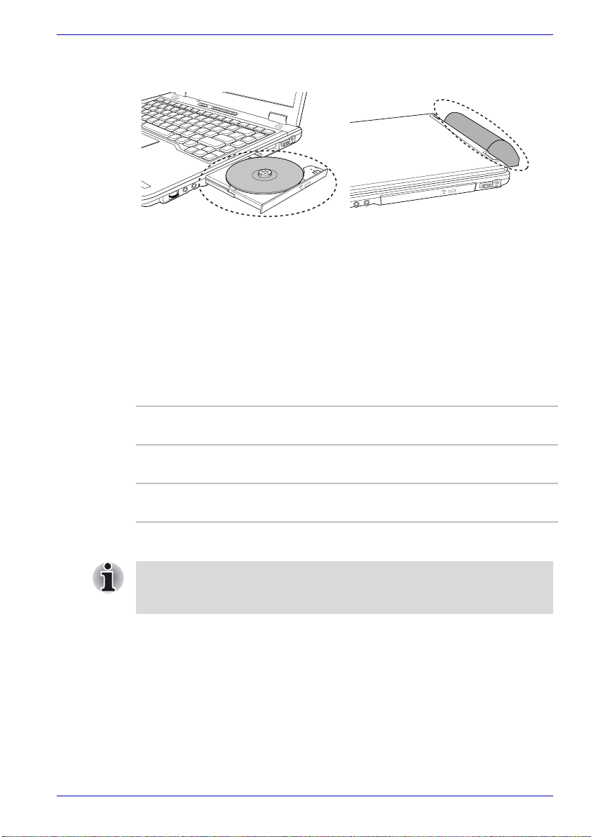
Heat dispersal
To protect from overheating, the CPU has an internal temperature sensor. If
the computer’s internal temperature rises to a certain level, the cooling fan
is turned on or the processing speed is lowered. You can select whether to
control the CPU temperature by turning on the fan first, then if necessary,
lowering the CPU speed. Or, by lowering the CPU speed first, then if
necessary, turning on the fan. Use the Cooling Method item of the Basic
Setup tab in TOSHIBA Power Saver.
Operating Basics
Protruded portions
Maximum
Performance
Performance Uses a combination of the fan and lowering the CPU
Battery
optimized
When the CPU temperature falls to a normal range, the fan is turned off
and the CPU operation returns to standard speed.
If the CPU temperature reaches an unacceptably high level with either
setting, the system automatically shuts down to prevent damage. Data in
memory will be lost.
User’s Manual 4-24
Turns on the fan first, then if necessary, lowers the CPU
processing speed.
processing speed.
Lowers the CPU processing speed first, then if necessary
turns on the fan.

TECRA A2
The Keyboard
The computer’s keyboard layouts are compatible with a 101/102-key
enhanced keyboard. By pressing some keys in combination, all the 101/
102-key keyboard functions can be executed on the computer.
The number of keys on your keyboard depends on which country/region’s
keyboard layout your computer is configured with. Keyboards for numerous
languages are available.
There are five types of keys: typewriter keys, keypad overlay, function keys,
soft keys and cursor control keys.
Typewriter keys
The typewriter keys produce the upper- and lower-case letters, numbers,
punctuation marks, and special symbols that appear on the screen.
There are some differences, however, between using a typewriter and
using a computer keyboard:
■ Letters and numbers produced in computer text vary in width. Spaces,
which are created by a “space character,” may also vary depending on
line justification and other factors.
■ The lowercase l (el) and the number 1 (one) are not interchangeable on
computers as they are on a typewriter.
■ The uppercase O (oh) and the 0 (zero) are not interchangeable.
■ The Caps Lock function key locks only the alphabetic characters in
uppercase while the shift lock on a typewriter places all keys in the
shifted position.
■ The Shift keys, the Ta b key, and the BkSp (backspace) key perform the
same function as their typewriter counterparts but also have special
computer functions.
Chapter 5
User’s Manual 5-1

F1 … F12 function keys
The function keys (not to be confused with Fn) are the 12 keys at the top of
your keyboard. These keys function differently from other keys.
F1 through F12 are called function keys because they execute
programmed functions when pressed. Used in combination with the Fn key,
keys marked with icons execute specific functions on the computer. Refer
to the section, Soft keys: Fn key combinations, in this chapter. The function
executed by individual keys depends on the software you are using.
Soft keys: Fn key combinations
The Fn (function) is unique to TOSHIBA computers and is used in
combination with other keys to form soft keys. Soft keys are key
combinations that enable, disable or configure specific features.
Some software may disable or interfere with soft-key operations. Soft-key
settings are not restored by the Standby Mode feature.
Emulating keys on enhanced keyboard
The Keyboard
Pause
PrtSc
Esc
F1
F3 F4 F5 F6 F7 F8 F9 F10 F11 F12
F2
Tab
~
`
CapsLock
Ctrl
Shift
#
!
1
QW RTYU IOP
$4%
@
2
3
E
ASDFGHJ KL
CXZB
Alt
&
^
68
5
7
V
_
(9 )
*
<
MN
,
+
{[}
?
/
Bk Sp
=
\
]
,,
Enter
,
Shift
Ctrl
-
0
:
;
>
.
Alt
SysReq
Scroll
Break
lock
Num
PgUp
Ins
Home
Del
End
PgDn
*
/
.
Lock
7
8 9
Home
PgUp
+
654
3
1
2
PgDn
End
0
Ins
Enter
.
Del
A 101-key enhanced keyboard layout
The keyboard is designed to provide all the features of the 101-key
enhanced keyboard, shown in figure above. The 101/102-key enhanced
keyboard has a numeric keypad and scroll lock key. It also has additional
Enter and Ctrl keys to the right of the main keyboard. Since the keyboard
is smaller and has fewer keys, some of the enhanced keyboard functions
must be simulated using two keys instead of one on the larger keyboard.
Your software may require you to use keys that the keyboard does not
have. Pressing the Fn key and one of the following keys simulates the
enhanced keyboard’s functions.
User’s Manual 5-2
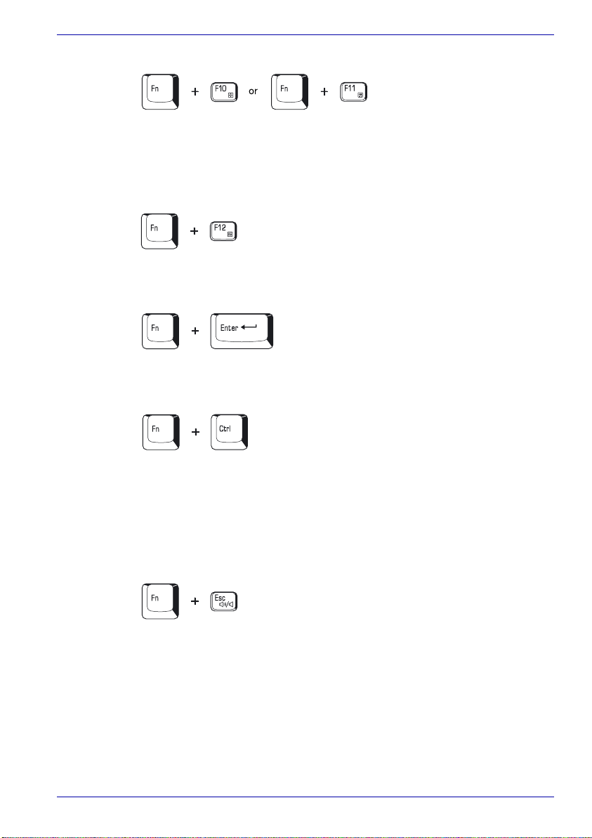
The Keyboard
Press Fn + F10 or Fn + F11 to access the integrated keypad. When
activated, the keys with gray markings on the bottom edge become
numeric keypad keys (Fn + F11) or cursor control keys (Fn + F10). Refer to
the Keypad overlay section in this chapter for more information on how to
operate these keys. The power on default for both settings is off.
Press Fn + F12 (ScrLock) to lock the cursor on a specific line. The power
on default is off.
Press Fn + Enter to simulate Enter on the enhanced keyboard’s numeric
keypad.
Press Fn + Ctrl to simulate the enhanced keyboard’s right Ctrl key.
Hot keys
Hot keys (Fn + a function or Esc key) let you enable or disable certain
features of the computers.
Sound mute: Pressing Fn + Esc in a Windows environment turns sound
on or off. When you press these hot keys, the current setting will change
and be displayed as an icon.
User’s Manual 5-3
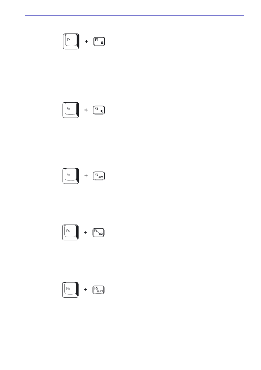
The Keyboard
Instant security: Press Fn + F1 to blank the screen to prevent others from
accessing your data. To restore the screen and original settings, press any
key or press the Dual Pointing Device. If a screensaver password is
registered, a dialog box will appear. Enter the screensaver password and
click OK. If no password is set, the screen will be restored when you press
any key or press the Dual Pointing Device.
Power save mode: Pressing Fn + F2 changes the power save mode.
If you press Fn + F2 in a Windows environment, the Power Save Mode is
displayed in a dialog box. Continue holding down Fn and press F2 again to
change the setting. You can also change this setting through the profile
item in TOSHIBA Power Saver.
Standby: When you press Fn + F3, the computer enters Standby Mode. To
avoid entering Standby Mode unexpectedly, a dialog box appears for
verification. However, if you select the check box, it will not appear in the
future.
Hibernation: When you press Fn + F4, the computer enters Hibernation
Mode. To avoid entering Hibernation Mode unexpectedly, a dialog box
appears for verification. However, if you select the check box, it will not
appear in the future.
Display selection: Press Fn + F5 to change the active display device.
When you press these hot keys, a dialog box appears. Only selectable
devices will be displayed. Hold down Fn and press F5 again to change the
device. When you release Fn and F5, the selected device will change. If
you hold down these hot keys for five seconds the selection will return to
LCD.
User’s Manual 5-4
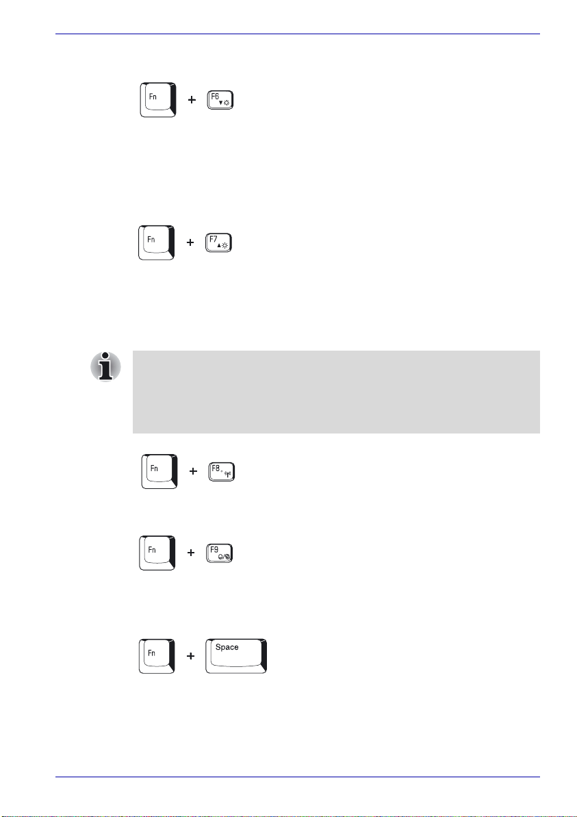
The Keyboard
LCD Display Brightness: Pressing Fn + F6 decreases the display
brightness in decrements. When you press these hot keys, the current
setting will be displayed for two seconds by an icon. You can also change
this setting through the Screen brightness item of the Basic Setup tab in
TOSHIBA Power Saver.
LCD Display Brightness: Pressing Fn + F7 increases the display
brightness in increments. When you press these hot keys, the current
setting will be displayed for two seconds by a pop-up icon. You can also
change this setting through the Screen brightness item of the Basic Setup
tab in TOSHIBA Power Saver.
.
■ The brightness level is always set at the maximum value for about
18 seconds, when the LCD turns on. After 18 seconds, the brightness
level will appear at the Power Save Mode setting or you can change it
manually.
■ Display clarity increases with the brightness level.
Wireless setting: Fn + F8 are not used.
Touch pad: Pressing Fn + F9 in a Windows environment enables or
disables the Touch pad function. When you press these hot keys, the
current setting will change and be displayed as an icon.
Display resolution selection: Press Fn + spacebar to change the display
resolution. Each time when you press these hot keys, the display resolution
changes as follows: From the current resolution (the original resolution) to
1024×768, from 1024×768 to 800×600, from 800×600 to the original
resolution.
User’s Manual 5-5

TOSHIBA Zooming Utility (reduce): To reduce the icon size on the
desktop or the application window, press the 1 key while holding down the
Fn key.
TOSHIBA Zooming Utility (enlarge): To enlarge the icon size on the
desktop or the application window, press the 2 key while holding down the
Fn key.
Fn Sticky key
You can use the TOSHIBA Accessibility Utility to make the Fn key sticky,
that is, you can press it once, release it, and then press an “F number” key.
To start the TOSHIBA Accessibility Utility, click start, point to All
Programs, point to TOSHIBA, point to Utilities and click Accessibility.
Windows special keys
The keyboard provides two keys that have special functions in Windows :
Windows logo key activates the start menu and the other, the application
key, has the same function as the secondary mouse button.
The Keyboard
This key activates the Windows start menu.
This key has the same function as the secondary mouse button.
Keypad overlay
Your computer’s keyboard does not have an independent numeric keypad,
but its numeric keypad overlay functions like one.
The keys in the center of the keyboard with gray letters make up the
numeric keypad overlay. The overlay provides the same functions as the
numeric keypad on the 101/102-key enhanced keyboard in next figure.
User’s Manual 5-6

Turning on the overlays
The numeric keypad overlay can be used for numeric data input or cursor
and page control.
Arrow mode
To turn on the Arrow mode, press Fn + F10. The Arrow mode F10 indicator
lights. Now try cursor and page control using the keys shown in figure
below. Press Fn + F10 again to turn off the overlay.
Numeric mode
To turn on the Numeric mode, press Fn + F11. The Numeric mode F11
indicator lights. Now try numeric data entry using the keys in figure below.
Press Fn + F11 again to turn off the overlay.
The Keyboard
The numeric keypad overlay
Temporarily using normal keyboard (overlay on)
While using the overlay, you can temporarily access the normal keyboard
without turning off the overlay:
1. Hold Fn and press any other key. All keys will operate as if the overlay
were off.
2. Type upper-case characters by holding Fn + Shift and pressing a
character key.
3. Release Fn to continue using the overlay.
User’s Manual 5-7

Temporarily using overlay (overlay off)
While using the normal keyboard, you can temporarily use the keypad
overlay without turning it on:
1. Press and hold down Fn.
2. Check the keyboard indicators. Pressing Fn turns on the most recently
used overlay. If the Numeric mode indicator lights, you can use the
overlay for numeric entry. If the Arrow mode indicator lights, you can
use the overlay for cursor and page control.
3. Release Fn to return to normal keyboard operation.
Temporarily changing modes
If the computer is in Numeric mode, you can switch temporarily to Arrow
mode by pressing a shift key.
If the computer is in Arrow mode, you can switch temporarily to Numeric
mode by pressing a shift key.
Generating ASCII characters
Not all ASCII characters can be generated using normal keyboard
operation. But, you can generate these characters using their ASCII codes.
With the overlay on:
1. Hold down Alt.
2. Using the overlay keys, type the ASCII code.
3. Release Alt, and the ASCII character appears on the display screen.
With the overlay off:
1. Hold down Alt + Fn.
2. Using the overlay keys, type the ASCII code.
3. Release Alt + Fn, and the ASCII character appears on the display
screen.
The Keyboard
User’s Manual 5-8

TECRA A2
Chapter 6
Power and Power-Up Modes
The computer’s power resources include the AC adaptor and internal
batteries. This chapter gives details on making the most effective use of
these resources including charging and changing batteries, tips for saving
battery power, and power up modes.
Power conditions
The computer’s operating capability and battery charge status are affected
by the power conditions: whether an AC adaptor is connected, whether a
battery is installed and what the charge level is for the battery.
Power conditions
Power on
Universal
AC
adaptor
connected
User’s Manual 6-1
Battery fully
charged
Battery partially
charged or no
charge
No battery
installed
• Operates
• LED: Battery green
DC IN 15V green
• Operates
• Quick Charge
• LED: Battery orange
DC IN 15V green
• Operates
• No charge
• LED: Battery off
DC IN 15V green
Power off
(no operation)
• LED: Battery green
DC IN 15V green
• Quick charge
• LED: Battery orange
DC IN 15V green
• No charge
• LED: Battery off
DC IN 15V green

Power and Power-Up Modes
Power conditions continued
Power on Power off
(no operation)
AC
adaptor
not
connected
Battery charge
is above low
battery trigger
point
Battery charge
is below low
battery trigger
point
Battery charge
is exhausted
No battery
installed
• Operates
• LED: Battery off
DC IN 15V off
• Operates
• LED: Battery
flashes orange
DC IN 15V off
Computer shuts down
• Cannot operate
• LED: Battery off
DC IN 15V
off
User’s Manual 6-2
 Loading...