

Page 1

User’s Manual
TECRA A8 / Satellite Pro A120
Page 2

Copyright
© 2006 by TOSHIBA Corporation. All rights reserved. Under the copyright
laws, this manual cannot be reproduced in any form without the prior
written permission of TOSHIBA. No patent liability is assumed, with respect
to the use of the information contained herein.
TOSHIBA TECRA A8 / Satellite Pro A120 Portable Personal Computer
User’s Manual
First edition May 2006
Copyright authority for music, movies, computer programs, data bases and
other intellectual property covered by copyright laws belongs to the author
or to the copyright owner. Copyrighted material can be reproduced only for
personal use or use within the home. Any other use beyond that stipulated
above (including conversion to digital format, alteration, transfer of copied
material and distribution on a network) without the permission of the
copyright owner is a violation of copyright or author’s rights and is subject
to civil damages or criminal action. Please comply with copyright laws in
making any reproduction from this manual.
Disclaimer
This manual has been validated and reviewed for accuracy. The
instructions and descriptions it contains are accurate for the TOSHIBA
TECRA A8 / Satellite Pro A120 Portable Personal Computer at the time of
this manual’s production. However, succeeding computers and manuals
are subject to change without notice. TOSHIBA assumes no liability for
damages incurred directly or indirectly from errors, omissions or
discrepancies between the computer and the manual.
Trademarks
IBM is a registered trademark and IBM PC is a trademark of International
Business Machines Corporation.
Intel, Intel SpeedStep, Intel Core and Centrino are trademarks or registered
trademarks of Intel Corporation or its subsidiaries in the United States and
other countries/regions.
Windows and Microsoft are registered trademarks of Microsoft Corporation.
Photo CD is a trademark of Eastman Kodak.
Sonic RecordNow! is a registered trademark of Sonic Solutions.
Bluetooth is a trademark owned by its proprietor and used by TOSHIBA
under license.
i.LINK is trademark and registered trademark of Sony Corporation.
InterVideo and WinDVD are registered trademarks of InterVideo Inc.
WinDVD Creator is trademark of InterVideo Inc.
Other trademarks and registered trademarks not listed above may be used
in this manual.
ii User’s Manual
Page 3

EU Declaration of Conformity
TOSHIBA declares, that the product: PTA82*/ PTA83*/ PSAC0*/ PSAC1*
conforms to the following Standards:
This product is labelled with the CE Mark in accordance with the related
European Directives, notably Electromagnetic Compatibility Directive
89/ 336/EEC for the notebook and the electronic accessories including the
supplied power adapter, the Radio Equipment and Telecommunications
Terminal Equipment Directive 99/5/EEC in case of implemented
telecommunication accessories and the Low Voltage Directive 73/23/EEC
for the supplied power adapter.
CE Marking is the responsibility of TOSHIBA EUROPE GmbH,
Hammfelddamm 8, 41460 Neuss, Germany, phone +49-(0)-2131-158-01.
For a copy of the related CE Declaration of Conformity please refer to the
following website: http://epps.toshiba-teg.com
This product and the supplied accessories are designed to observe the
related EMC (Electromagnetic Compatibility) and safety standards.
However, Toshiba cannot guarantee that this product still observes these
EMC standards if accessories or cables not manufactured / distributed by
Toshiba are connected or implemented. To avoid in general EMC problems,
the following advice should be observed:
■ Only CE marked accessories should be connected / implemented
■ Only best shielded cables should be connected
Following information is only for EU-member states:
The use of the symbol indicates that this product may not be treated as
household waste. By ensuring this product is disposed of correctly, you will
help prevent potential negative consequences for the environment and
human health, which could otherwise be caused by inappropriate waste
handling of this product. For more detailed information about recycling of
this product, please contact your local city office, your household waste
disposal service or the shop where you purchased the product.
User’s Manual iii
Page 4

Modem warning notice
Conformity Statement
The equipment has been approved to [Commission Decision “CTR21”] for
pan-European single terminal connection to the Public Switched Telephone
Network (PSTN).
However, due to differences between the individual PSTNs provided in
different countries/regions the approval does not, of itself, give an
unconditional assurance of successful operation on every PSTN network
termination point.
In the event of problems, you should contact your equipment supplier in the
first instance.
Network Compatibility Statement
This product is designed to work with, and is compatible with the following
networks. It has been tested to and found to conform with the additional
requirements conditional in EG 201 121.
Germany ATAAB AN005,AN006,AN007,AN009,AN010
Greece ATAAB AN005,AN006 and GR01,02,03,04
Portugal ATAAB AN001,005,006,007,011 and
Spain ATAAB AN005,007,012, and ES01
Switzerland ATAAB AN002
All other countries/regions ATAAB AN003,004
Specific switch settings or software setup are required for each network,
please refer to the relevant sections of the user guide for more details.
The hookflash (timed break register recall) function is subject to separate
national type approvals. It has not been tested for conformity to national
type regulations, and no guarantee of successful operation of that specific
function on specific national networks can be given.
and DE03,04,05,08,09,12,14,17
P03,04,08,10
iv User’s Manual
Page 5
Optical disc drive safety instructions
The optical disc drive employs a laser system. To ensure proper use of this
product, please read the manual carefully and retain for future reference.
Should the unit ever require maintenance, contact an authorized service
location.
Use of controls, adjustments or the performance of procedures other than
those specified may result in hazardous radiation exposure.
To prevent direct exposure to the laser beam, do not try to open the
enclosure.
USE OF CONTROLS OR ADJUSTMENTS OR PERFORMANCE OF
PROCEDURES OTHER THAN THOSE SPECIFIED IN THE MANUAL
MAY RESULT IN HAZARDOUS RADIATION EXPOSURE.
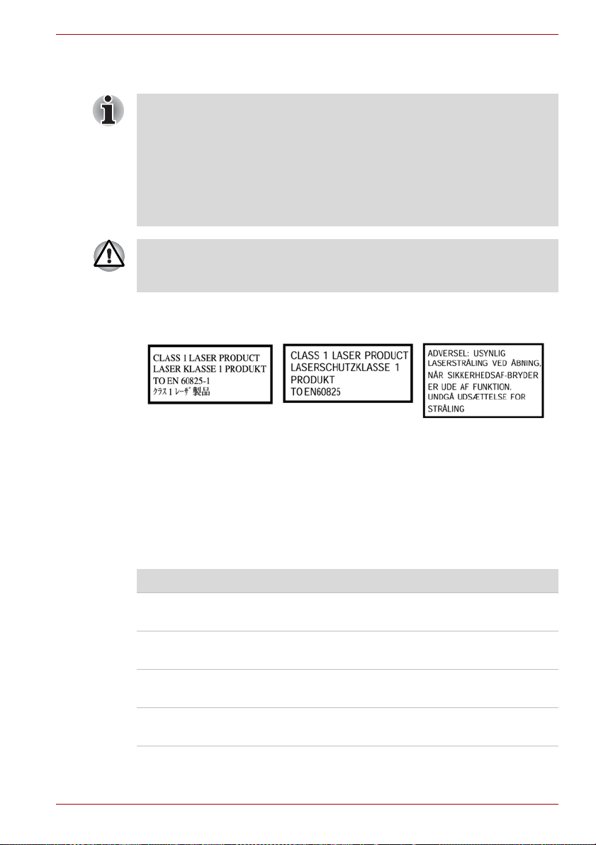
The optical drive that is used in this computer is equipped with a laser
device. A classification label with the following sentence is affixed to the
surface of the drive.
The drive with the label above is certified by the manufacturer that the drive
complies with the requirement for laser product on the date of
manufacturing pursuant to article 21 of Code of Federal Regulations by the
United States of America, Department of Health & Human Services, Food
and Drug Administration.
In other countries, the drive is certified to comply with the requirement
pursuant to IEC 825 and EN60825 on class 1 laser product.
This computer is equipped with one of the optical drive in the following list
according to the model:
Manufacturer Type
Panasonic DVD Super Multi (±R Double Layer)
UJ-841BJTJ-J
Panasonic DVD-ROM&CD-R/RW
UJDA770TB-A
TEAC DVD ROM
DV-28E-RT4
TEAC CD ROM
CD 224E-NT4
User’s Manual v
Page 6

vi User’s Manual
Page 7

Table of Contents
Preface
General Precautions
Chapter 1 Introduction
Equipment checklist. . . . . . . . . . . . . . . . . . . . . . . . . . . . . . . . . . . . . . . 1-1
Features. . . . . . . . . . . . . . . . . . . . . . . . . . . . . . . . . . . . . . . . . . . . . . . . . 1-3
Special features . . . . . . . . . . . . . . . . . . . . . . . . . . . . . . . . . . . . . . . . . 1-11
Utilities. . . . . . . . . . . . . . . . . . . . . . . . . . . . . . . . . . . . . . . . . . . . . . . . . 1-13
Options . . . . . . . . . . . . . . . . . . . . . . . . . . . . . . . . . . . . . . . . . . . . . . . . 1-16
Chapter 2 The Grand Tour
Front with the display closed . . . . . . . . . . . . . . . . . . . . . . . . . . . . . . . 2-1
Left side. . . . . . . . . . . . . . . . . . . . . . . . . . . . . . . . . . . . . . . . . . . . . . . . . 2-3
Right side . . . . . . . . . . . . . . . . . . . . . . . . . . . . . . . . . . . . . . . . . . . . . . . 2-4
Back side. . . . . . . . . . . . . . . . . . . . . . . . . . . . . . . . . . . . . . . . . . . . . . . . 2-4
Underside . . . . . . . . . . . . . . . . . . . . . . . . . . . . . . . . . . . . . . . . . . . . . . . 2-7
Front with the display open. . . . . . . . . . . . . . . . . . . . . . . . . . . . . . . . . 2-8
System indicators. . . . . . . . . . . . . . . . . . . . . . . . . . . . . . . . . . . . . . . . 2-10
Keyboard indicators. . . . . . . . . . . . . . . . . . . . . . . . . . . . . . . . . . . . . . 2-11
USB floppy disk drive . . . . . . . . . . . . . . . . . . . . . . . . . . . . . . . . . . . . 2-12
Optical disk drives . . . . . . . . . . . . . . . . . . . . . . . . . . . . . . . . . . . . . . . 2-13
AC adaptor . . . . . . . . . . . . . . . . . . . . . . . . . . . . . . . . . . . . . . . . . . . . . 2-16
Chapter 3 Getting Started
Connecting the AC adaptor . . . . . . . . . . . . . . . . . . . . . . . . . . . . . . . . . 3-2
Opening the display . . . . . . . . . . . . . . . . . . . . . . . . . . . . . . . . . . . . . . . 3-4
Turning on the power . . . . . . . . . . . . . . . . . . . . . . . . . . . . . . . . . . . . . . 3-5
Starting up for the first time . . . . . . . . . . . . . . . . . . . . . . . . . . . . . . . . 3-5
Turning off the power. . . . . . . . . . . . . . . . . . . . . . . . . . . . . . . . . . . . . . 3-6
Restarting the computer . . . . . . . . . . . . . . . . . . . . . . . . . . . . . . . . . . 3-10
Restoring the preinstalled software from
the Product Recovery Media. . . . . . . . . . . . . . . . . . . . . . . . . . . . . . 3-10
User’s Manual vii
Page 8

Chapter 4 Operating Basics
Using the Touch Pad . . . . . . . . . . . . . . . . . . . . . . . . . . . . . . . . . . . . . . .4-1
Using the USB floppy disk drive. . . . . . . . . . . . . . . . . . . . . . . . . . . . . .4-2
Using optical disk drives. . . . . . . . . . . . . . . . . . . . . . . . . . . . . . . . . . . .4-3
Writing CDs on DVD-ROM&CD-R/RW drive . . . . . . . . . . . . . . . . . . . . .4-6
Writing CD/DVDs on DVD Super Multi drive . . . . . . . . . . . . . . . . . . . .4-8
Media care. . . . . . . . . . . . . . . . . . . . . . . . . . . . . . . . . . . . . . . . . . . . . . .4-17
Sound system. . . . . . . . . . . . . . . . . . . . . . . . . . . . . . . . . . . . . . . . . . . .4-18
Modem. . . . . . . . . . . . . . . . . . . . . . . . . . . . . . . . . . . . . . . . . . . . . . . . . .4-19
Wireless communications . . . . . . . . . . . . . . . . . . . . . . . . . . . . . . . . . .4-22
LAN . . . . . . . . . . . . . . . . . . . . . . . . . . . . . . . . . . . . . . . . . . . . . . . . . . . .4-26
Cleaning the computer . . . . . . . . . . . . . . . . . . . . . . . . . . . . . . . . . . . .4-27
Moving the computer. . . . . . . . . . . . . . . . . . . . . . . . . . . . . . . . . . . . . .4-28
Using the Hard Disk Drive (HDD) Protection . . . . . . . . . . . . . . . . . . .4-28
Heat dispersal. . . . . . . . . . . . . . . . . . . . . . . . . . . . . . . . . . . . . . . . . . . .4-31
Chapter 5 The Keyboard
Typewriter keys . . . . . . . . . . . . . . . . . . . . . . . . . . . . . . . . . . . . . . . . . . .5-1
Function keys: F1 … F12. . . . . . . . . . . . . . . . . . . . . . . . . . . . . . . . . . . .5-2
Soft keys: Fn key combinations . . . . . . . . . . . . . . . . . . . . . . . . . . . . . .5-2
Hot keys . . . . . . . . . . . . . . . . . . . . . . . . . . . . . . . . . . . . . . . . . . . . . . . . .5-3
Windows special keys . . . . . . . . . . . . . . . . . . . . . . . . . . . . . . . . . . . . . .5-7
Keypad overlay. . . . . . . . . . . . . . . . . . . . . . . . . . . . . . . . . . . . . . . . . . . .5-7
Generating ASCII characters. . . . . . . . . . . . . . . . . . . . . . . . . . . . . . . . .5-9
Chapter 6 Power and Power-Up Modes
Power conditions . . . . . . . . . . . . . . . . . . . . . . . . . . . . . . . . . . . . . . . . . .6-1
Power indicators . . . . . . . . . . . . . . . . . . . . . . . . . . . . . . . . . . . . . . . . . .6-2
Battery types. . . . . . . . . . . . . . . . . . . . . . . . . . . . . . . . . . . . . . . . . . . . . .6-3
Care and use of the battery pack . . . . . . . . . . . . . . . . . . . . . . . . . . . . .6-5
Replacing the battery pack . . . . . . . . . . . . . . . . . . . . . . . . . . . . . . . . .6-10
TOSHIBA Password Utility . . . . . . . . . . . . . . . . . . . . . . . . . . . . . . . . .6-12
Power-up modes . . . . . . . . . . . . . . . . . . . . . . . . . . . . . . . . . . . . . . . . .6-15
Panel power on/off . . . . . . . . . . . . . . . . . . . . . . . . . . . . . . . . . . . . . . . .6-15
System Auto Off . . . . . . . . . . . . . . . . . . . . . . . . . . . . . . . . . . . . . . . . . .6-15
Chapter 7 HW Setup
Accessing HW Setup . . . . . . . . . . . . . . . . . . . . . . . . . . . . . . . . . . . . . . .7-1
HW Setup window . . . . . . . . . . . . . . . . . . . . . . . . . . . . . . . . . . . . . . . . .7-1
Starting and Ending the BIOS Setup Program . . . . . . . . . . . . . . . . . .7-9
viii User’s Manual
Page 9

Chapter 8 Optional Devices
PC card . . . . . . . . . . . . . . . . . . . . . . . . . . . . . . . . . . . . . . . . . . . . . . . . . 8-2
SD card . . . . . . . . . . . . . . . . . . . . . . . . . . . . . . . . . . . . . . . . . . . . . . . . . 8-3
Memory expansion . . . . . . . . . . . . . . . . . . . . . . . . . . . . . . . . . . . . . . . . 8-6
Battery pack . . . . . . . . . . . . . . . . . . . . . . . . . . . . . . . . . . . . . . . . . . . . 8-10
AC adaptor . . . . . . . . . . . . . . . . . . . . . . . . . . . . . . . . . . . . . . . . . . . . . 8-10
Battery charger . . . . . . . . . . . . . . . . . . . . . . . . . . . . . . . . . . . . . . . . . . 8-10
USB floppy disk drive . . . . . . . . . . . . . . . . . . . . . . . . . . . . . . . . . . . . 8-10
External monitor . . . . . . . . . . . . . . . . . . . . . . . . . . . . . . . . . . . . . . . . . 8-10
TV . . . . . . . . . . . . . . . . . . . . . . . . . . . . . . . . . . . . . . . . . . . . . . . . . . . . . 8-11
i.LINK (IEEE1394) . . . . . . . . . . . . . . . . . . . . . . . . . . . . . . . . . . . . . . . . 8-13
Advanced Port Replicator III Plus . . . . . . . . . . . . . . . . . . . . . . . . . . . 8-15
Serial port . . . . . . . . . . . . . . . . . . . . . . . . . . . . . . . . . . . . . . . . . . . . . . 8-16
Security lock . . . . . . . . . . . . . . . . . . . . . . . . . . . . . . . . . . . . . . . . . . . . 8-17
Chapter 9 Troubleshooting
Problem solving process. . . . . . . . . . . . . . . . . . . . . . . . . . . . . . . . . . . 9-1
Hardware and system checklist . . . . . . . . . . . . . . . . . . . . . . . . . . . . . 9-3
TOSHIBA support . . . . . . . . . . . . . . . . . . . . . . . . . . . . . . . . . . . . . . . . 9-22
Chapter 10 Legal Footnotes
Appendix A Specifications
Appendix B Display Controller and Modes
Display controller . . . . . . . . . . . . . . . . . . . . . . . . . . . . . . . . . . . . . . . . . B-1
Video modes . . . . . . . . . . . . . . . . . . . . . . . . . . . . . . . . . . . . . . . . . . . . . B-1
Appendix C Wireless LAN
Card Specifications . . . . . . . . . . . . . . . . . . . . . . . . . . . . . . . . . . . . . . . C-1
Radio Characteristics. . . . . . . . . . . . . . . . . . . . . . . . . . . . . . . . . . . . . . C-1
Supported Frequency Sub-bands. . . . . . . . . . . . . . . . . . . . . . . . . . . . C-2
Appendix D Bluetooth wireless technology Interoperability
Bluetooth wireless technology and your Health . . . . . . . . . . . . . . . . D-3
Regulatory statements. . . . . . . . . . . . . . . . . . . . . . . . . . . . . . . . . . . . . D-3
Using Bluetooth™ Card from TOSHIBA equipment in Japan . . . . . D-5
Appendix E AC Power Cord and Connectors
Certification agencies . . . . . . . . . . . . . . . . . . . . . . . . . . . . . . . . . . . . . E-1
Appendix F TOSHIBA Anti-theft Protection Timer
Appendix G If your computer is stolen
Glossary
Index
User’s Manual ix
Page 10

x User’s Manual
Page 11

Preface
Congratulations on your purchase of the TECRA A8 / Satellite Pro A120
computer. This powerful notebook computer provides excellent expansion
capability, including multimedia devices, and it is designed to provide years
of reliable, high-performance computing.
This manual tells how to set up and begin using your TECRA A8 / Satellite
Pro A120 computer. It also provides detailed information on configuring
your computer, basic operations and care, using optional devices and
troubleshooting.
If you are a new user of computers or if you’re new to portable computing,
first read over the Introduction and The Grand Tour chapters to familiarize
yourself with the computer’s features, components and accessory devices.
Then read Getting Started for step-by-step instructions on setting up your
computer.
If you are an experienced computer user, please continue reading the
preface to learn how this manual is organized, then become acquainted
with this manual by browsing through its pages. Be sure to look over the
Special features section of the Introduction, to learn about features that are
uncommon or unique to the computers and carefully read HW Setup.
If you are going to install PC cards or connect external devices such as a
monitor, be sure to read Chapter 8, Optional Devices.
Manual contents
This manual is made up of the following.
Chapter 1, Introduction, is an overview of the computer’s features,
capabilities, and options.
Chapter 2, The Grand Tour, identifies the components of the computer and
briefly explains how they function.
Chapter 3, Getting Started, provides a quick overview of how to begin
operating your computer and gives tips on safety and designing your work
area.
Chapter 4, Operating Basics, describes the basic operations of your
computer and precautions when using it, as well as the handling of
CD/DVD.
Chapter 5, The Keyboard, describes special keyboard functions including
the keypad overlay and hot keys.
User’s Manual xi
Page 12

Preface
Chapter 6, Power and Power-Up Modes, gives details on the computer’s
power resources and battery save modes and how to set a password.
Chapter 7, HW Setup, explains how to configure the computer using the
HW Setup program and TPM.
Chapter 8, Optional Devices, describes the optional hardware available.
Chapter 9, Troubleshooting, provides helpful information on how to perform
some diagnostic tests, and suggests courses of action if the computer
doesn’t seem to be working properly.
Chapter 10, Legal Footnotes, provides Legal Footnote information related
to your computer.
The Appendixes provide technical information about your computer.
The Glossary defines general computer terminology and includes a list of
acronyms used in the text.
The Index quickly directs you to the information contained in this manual.
Conventions
This manual uses the following formats to describe, identify, and highlight
terms and operating procedures.
Abbreviations
On first appearance, and whenever necessary for clarity, abbreviations are
enclosed in parentheses following their definition. For example: Read Only
Memory (ROM). Acronyms are also defined in the Glossary.
Icons
Icons identify ports, dials, and other parts of your computer. The indicator
panel also uses icons to identify the components it is providing information
on.
Keys
The keyboard keys are used in the text to describe many computer
operations. A distinctive typeface identifies the key top symbols as they
appear on the keyboard. For example, Enter identifies the Enter key.
Key operation
Some operations require you to simultaneously use two or more keys. We
identify such operations by the key top symbols separated by a plus sign
(+). For example, Ctrl + C means you must hold down Ctrl and at the same
time press C. If three keys are used, hold down the first two and at the
same time press the third.
ABC
xii User’s Manual
When procedures require an action such as
clicking an icon or entering text, the icon’s name
or the text you are to type in is represented in the
type face you see to the left.
Page 13

Display
Preface
S ABC
Names of windows or icons or text generated by
the computer that appear on its display screen
are presented in the type face you see to the left.
Messages
Messages are used in this manual to bring important information to your
attention. Each type of message is identified as shown below.
Pay attention! A caution informs you that improper use of equipment or
failure to follow instructions may cause data loss or damage your
equipment.
Please read. A note is a hint or advice that helps you make best use of
your equipment.
Indicates a potentially hazardous situation, which could result in death or
serious injury, if you do not follow instructions.
User’s Manual xiii
Page 14

Preface
xiv User’s Manual
Page 15

General Precautions
TOSHIBA computers are designed to optimize safety, minimize strain and
withstand the rigors of portability. However, certain precautions should be
observed to further reduce the risk of personal injury or damage to the
computer.
Be certain to read the general precautions below and to note the cautions
included in the text of the manual.
Creating a computer-friendly environment
Place the computer on a flat surface that is large enough for the computer
and any other items you are using, such as a printer. Leave enough space
around the computer and other equipment to provide adequate ventilation.
Otherwise, they may overheat.To keep your computer in prime operating
condition, protect your work area from:
■ Dust, moisture, and direct sunlight.
■ Equipment that generates a strong electromagnetic field, such as
stereo speakers (other than speakers that are connected to the
computer) or speaker phones.
■ Rapid changes in temperature or humidity and sources of temperature
change such as air conditioner vents or heaters.
■ Extreme heat, cold, or humidity.
■ Liquids and corrosive chemicals.
Stress injury
Carefully read the Instruction Manual for Safety & Comfort. It contains
information on prevention of stress injuries to your hands and wrists that
can be caused by extensive keyboard use. Chapter 3, Getting Started, also
includes information on work space design, posture and lighting that can
help reduce physical stress.
User’s Manual xv
Page 16

General Precautions
Heat injury
■ Avoid prolonged physical contact with the computer. If the computer is
used for long periods, its surface can become very warm. While the
temperature will not feel hot to the touch, if you maintain physical
contact with the computer for a long time (if you rest the computer on
your lap, or if you keep your hands on the palm rest, for example) your
skin might suffer low-heat injury.
■ If the computer has been used for a long time, avoid direct contact with
the metal plate supporting the I/O ports. It can become hot.
■ The surface of the AC adaptor can become hot when in use. This
condition does not indicate a malfunction. If you need to transport the
AC adaptor, disconnect it and let it cool before moving it.
■ Do not lay the AC adaptor on a material that is sensitive to heat. The
material could be damaged.
Pressure or impact damage
Do not apply heavy pressure to the computer or subject it to strong impact.
Excessive pressure or impact can cause damage to computer components
or otherwise cause malfunctions.
PC card overheating
Some PC cards can become hot with prolonged use. Overheating of a PC
card can result in errors or instability in the PC card operation. Also be
careful when you remove a PC card that has been used for a long time.
Mobile phone
Use of mobile phones can interfere with the audio system. Computer
operation is not impaired but it is recommended that a distance of 30 cm be
maintained between the computer and a mobile phone in use.
Instruction Manual for Safety & Comfort
All important information on the safe and proper use of this computer is
described in the enclosed Instruction Manual for Safety & Comfort. Be sure
to read it before using the computer.
xvi User’s Manual
Page 17
Introduction
This chapter provides an equipment checklist, and it identifies the
computer’s features, options and accessories.
Some of the features described in this manual may not function properly if
you use an operating system that was not preinstalled by TOSHIBA.
Equipment checklist
Carefully unpack your computer. Save the box and packing materials for
future use.
An asterisk * indicates a optional part that is dependant on the model
purchased
Hardware
Check to make sure you have all the following items:
■ TECRA A8 / Satellite Pro A120 Portable Personal Computer
■ AC adaptor and power cord (2-pin plug or 3-pin plug)
■ USB floppy disk drive (Option or provided with some models)
■ Battery pack *
Chapter 1
User’s Manual 1-1
Page 18

Introduction
Software
Microsoft® Windows XP
■ The following software is preinstalled:
An asterisk * indicates some software that is not preinstalled dependant on
the model purchased.
■ Microsoft® Windows XP
■ Modem Driver
■ Network Driver
■ Wireless LAN driver (Can be used only for Wireless LAN models)
■ Bluetooth Driver (Can be used only for Bluetooth models)
■ Display Drivers for Windows
■ Sound Driver for Windows
■ Pointing Device Driver
■ DVD Video Player
■ TOSHIBA Utilities
■ TOSHIBA Power Saver
■ TOSHIBA User’s Manual
■ TOSHIBA Assist
■ TOSHIBA ConfigFree
■ TOSHIBA Touch Pad On/Off Utility
■ TOSHIBA PC Diagnostic Tool
■ TOSHIBA Zooming Utility
■ TOSHIBA Controls
■ TOSHIBA Acoustic Silencer
■ TOSHIBA Hotkey Utility
■ TOSHIBA SD Memory Card Format Utility
■ TOSHIBA SD Memory Boot Utility
■ TOSHIBA HDD Protection
■ TOSHIBA Display Device Change Utility
■ TOSHIBA Password Utility
■ TOSHIBA Security Assist
■ Sun Java 2 Runtime Environment
■ Atheros Client Utility
■ Intel PROSET Utility
■ TOSHIBA Mobile Extension3 *
■ TOSHIBA Management Console *
■ TOSHIBA Fingerprint Software *
■ TPM Software *
1-2 User’s Manual
Page 19

■ RecordNow!Basic for TOSHIBA *
■ DLA for TOSHIBA *
■ TOSHIBA DVD-RAM driver *
■ WinDVD Creator 2 Platinium *
Documentation
■ TECRA A8 / Satellite Pro A120 Portable Personal Computer User’s
Manual
■ TECRA A8 / Satellite Pro A120 Quickstart
■ Instruction Manual for Safety & Comfort
■ Warranty Information
Product Recover y Media and Additional Software
■ Product Recovery
■ Additional Software *
If any of the items are missing or damaged, contact your dealer
immediately.
Features
The computer uses TOSHIBA’s advanced Large Scale Integration (LSI),
Complementary Metal-Oxide Semiconductor (CMOS) technology
extensively to provide compact size, minimum weight, low power usage,
and high reliability. This computer incorporates the following features and
benefits:
Introduction
Processor
Built-in The computer is equipped with one of the
following Intel
■ Intel® Core™ Duo Processor, which
incorporates a 2MB level 2 cache memory.
It also supports Enhanced Intel
Technology.
■ Intel
incorporates a 2MB level 2 cache memory.
It also supports Enhanced Intel® SpeedStep®
Technology.
■ Intel
incorporates a 1MB level 2 cache memory.
User’s Manual 1-3
®
processors.
®
SpeedStep®
®
Core™ Solo Processor, which
®
Celeron® M Processor, which
Page 20

Introduction
Some models in this series carry Intel® Centrino® Duo Mobile Technology,
which is based on three separate technologies of Intel
processor, Intel
®
PRO/Wireless Network Connection, and Mobile Intel®
®
Core™ Duo
945 Express Chipset Family.
Some models of the computers carry Intel® Centrino® Mobile Technology,
which is based on three separate technologies of Intel
processor, Intel
®
PRO/Wireless Network Connection, and Mobile Intel®
®
Core™ Solo
945 Express Chipset Family.
Legal Footnote (CPU)*1
For more information on the Legal Footnote regarding CPU, please refer to
the Legal Footnotes section in Chapter 10. Click the *1.
Memory
Slots 256, 512, 1,024 or 2,048 MB memory modules
can be installed in the two memory slots for a
maximum of 4,096 MB. (Intel
Processor model)
256, 512, or 1,024 MB memory modules can be
installed in the two memory slots for a maximum
of 2,048 MB. (Intel® Celeron® M Processor model)
Video RAM Part of system memory is used for Video RAM.
®
Celeron® M Processor model:
Intel
up to 128MB
®
Intel
Core™ Duo/Solo Processor model:
up to 128MB (Main memory size: 256MB)
up to 256MB (Main memory size: 512MB,
768MB, 1,024MB or more).
®
Core™ Duo/Solo
Legal Footnote (General Main Memory)*2
For more information on the Legal Footnote regarding General Main
Memory, please refer to the Legal Footnotes section in Chapter 10. Click
the *2.
Power
Battery pack The computer is powered by one rechargeable
lithium-ion battery pack.
1-4 User’s Manual
Page 21

Introduction
Legal Footnote (Battery Life)*3
For more information on the Legal Footnote regarding Battery Life, please
refer to the Legal Footnotes section in Chapter 10. Click the *3.
RTC battery The internal RTC battery backs up the Real Time
Clock (RTC) and calendar.
AC adaptor The AC adaptor provides power to the system
and recharges the batteries when they are low. It
comes with a detachable power cord which will
either have a 2-pin or 3-pin plug enclosure.
Because it is universal, it can receive a range of
AC voltage from 100 to 240 volts; however, the
output current varies among different models.
Using the wrong model can damage your
computer. Refer to the AC adaptor section in
Chapter 2, The Grand Tour.
Disks
Hard Disk Drive
(HDD) Capacity
Available in five sizes.
■ 40.0 billion bytes (37.26 GB)
■ 60.0 billion bytes (55.89 GB)
■ 80.0 billion bytes (74.53 GB)
■ 100.0 billion bytes (93.16 GB)
■ 120.0 billion bytes (111.79 GB)
Part of the space in the hard disk drive is
reserved as administration space.
Legal Footnote (Hard Disk Drive (HDD) Capacity)*4
For more information on the Legal Footnote regarding Hard Disk Drive
(HDD) Capacity, please refer to the Legal Footnotes section in Chapter 10.
Click the *4.
USB floppy disk
drive
Accommodates either 3 1/2" 1.44-megabyte or
720-kilobyte floppy disk. It connects to a USB
port. Optional or provide with some models.
Optical disk drive
Computers in this series can be configured with an optical disk drive
installed. The available optical disk drives are described below.
User’s Manual 1-5
Page 22

Introduction
CD-ROM drive Some models are equipped with a full-size,
CD-ROM drive module that lets you run CD
without using an adaptor. It reads CD-ROMs at
maximum 24 speed. This drive supports the
following formats:
■ CD-DA
■ CD-Text
■ Photo CD™ (single/multi-session)
■ CD-ROM Mode 1, Mode 2
■ CD-ROM XA Mode 2 (Form1, Form2)
■ Enhanced CD (CD-EXTRA)
■ Addressing Method 2
DVD-ROM drive Some models are equipped with a full-size,
DVD-ROM drive module that lets you run either
12 cm (4.72") or 8 cm (3.15") CDs or 12cm
(4.72") DVDs without using an adaptor. It runs
DVD-ROMs at maximum 8 speed and CD-ROMs
at maximum 24 speed. The drive supports the
following formats:
■ DVD-ROM
■ DVD-Video
■ CD-DA
■ CD-Text
■ Photo CD™ (single/multi-session)
■ CD-ROM Mode 1, Mode 2
■ CD-ROM XA Mode 2 (Form1, Form2)
■ Enhanced CD (CD-EXTRA)
■ Addressing Method 2
DVD-ROM&CD-R/RW
drive
Some models are equipped with a full-size,
DVD-ROM&CD-R/RW drive module that lets you
run CD/DVDs without using an adaptor. It reads
DVD-ROMs at maximum 8 speed and CD-ROMs
at maximum 24 speed. It writes CD-R at up to
24 speed and CD-RW at up to 24 speed. This
drive supports the following formats in addition to
DVD-ROM drive.
■ CD-R
■ CD-RW
1-6 User’s Manual
Page 23

Introduction
DVD Super Multi
drive
2.6GB and 5.2GB DVD-RAM discs cannot be read from or written to.
Some models are equipped with a full-size DVD
Super Multi drive module that lets you record
data to rewritable CD/DVDs as well as run either
12cm (4.72") or 8cm (3.15") CD/DVDs without
using an adaptor. It reads DVD-ROMs at
maximum 8 speed and CD-ROMs at maximum
24 speed. It writes CD-R at maximum 24 speed,
CD-RW at maximum 10 speed, DVD-R and
DVD+R at maximum 8 speed, DVD-RW and
DVD+RW at maximum 4 speed, DVD-R DL at
maximum 2 speed, DVD+R DL at maximum
2.4 speed, DVD-RAM at maximum 5 speed.This
drive supports the following formats in addition to
DVD-ROM&CDR/ RW drive.
■ DVD-R
■ DVD-RW
■ DVD-RAM
■ DVD-R DL
■ DVD+R
■ DVD+RW
■ DVD+R DL
Display
The computer’ LCD display panel supports high-resolution video graphics.
The LCD screen can be set at a wide range of viewing angles for maximum
comfort and readability.
Built-in 15.4" TFT LCD screen, 16 million colors, with
one of the following resolution:
■ WXGA, 1280 horizontal × 800 vertical pixels
Legal Footnote (LCD)*5
For more information on the Legal Footnote regarding LCD, please refer to
the Legal Footnotes section in Chapter 10. Click the *5.
Graphics controller The graphics controller maximizes display
performance. Refer to Appendix B, Display
Controller and Modes, for more information.
User’s Manual 1-7
Page 24

Introduction
Legal Footnote (Graphics Processor Unit (“GPU”))*6
For more information on the Legal Footnote regarding Graphics Processor
Unit (“GPU”), please refer to the Legal Footnotes section in Chapter 10.
Click the *6.
Keyboard
Built-in
85 keys or 87 keys, compatible with IBM®
enhanced keyboard, embedded numeric overlay,
dedicated cursor control, and keys.
Refer to Chapter 5, The Keyboard, for details.
TOSHIBA Pointing Device
Built-in Touch Pad A Touch Pad and control buttons in the palm rest
enable control of the on-screen pointer and
scrolling of windows.
Ports
Serial RS-232C compatible port (16550UART
compatible).
Depending on the model, a serial port is not
present.
External monitor Analog VGA port supports VESA DDC2B
compatible functions.
Universal Serial Bus
(USB 2.0)
Docking This port enables connection of an optional
The computer has three Universal Serial Bus
ports that comply with the USB 2.0 standard.
Advanced Port Replicator III Plus described in
the Options section.
Depending on the model, a docking port is not
present.
Slots
PC card The PC card slot accommodates a Type II card.
SD card
1-8 User’s Manual
This slot lets you easily transfer data from
devices, such as digital cameras and Personal
Digital Assistants that use SD card flash memory.
Refer to Chapter 8, Optional Devices.
Page 25

Multimedia
Introduction
Sound system The Windows sound system compatible sound
system provides output to internal speakers and
a microphone as well as supporting jacks for an
external microphone and headphones.
Video-out jack
(S-Video)
The video out jack lets you transfer video data to
external devices. Data output depends on the
type of device connected to the S-Video cable.
Depending on the model, a Video out jack is not
present.
Headphone jack A 3.5 mm mini headphone jack enables
connection of stereo headphones.
Microphone jack A 3.5 mm mini microphone jack enables
connection of a three-conductor mini jack for
monaural microphone input.
Communications
Modem An internal modem provides capability for data
and fax communication supporting the V.90
(V.92) standards. The speed of data transfer and
fax depends on analog telephone line conditions.
It has a modem jack for connecting to a
telephone line. It is preinstalled as a standard
device in some markets. Both the V.90 and V.92
standards are supported only in the USA,
Canada, UK, France, Germany and Australia.
Only V.90 is available in other regions.
LAN This computer has built-in support for Ethernet
LAN (10 megabits per second, 10BASE-T), Fast
Ethernet LAN (100 megabits per second,
100BASE-TX) or Gigabit Ethernet LAN
(1000 megabits per second, 1000BASE-T (only
®
for Intel
Bluetooth Some computers in this series are equipped with
Bluetooth functions. Bluetooth wireless
technology eliminates the need for cables
between electronic devices such as computers
and printers. Bluetooth provides fast, reliable,
and secure wireless communication in a small
space.
Core™ Duo/Solo Processor model)).
User’s Manual 1-9
Page 26

Introduction
Wireless LAN The computers in this series are equipped with a
Wireless LAN card that is compatible with other
LAN systems based on Direct Sequence Spread
Spectrum/Orthogonal Frequency Division
Multiplexing radio technology that complies with
the IEEE 802.11 Standard (Revision A, B or G).
■ Theoretical maximum speed: 54Mbps
(IEEE802.11a, 802.11g)
■ Theoretical maximum speed: 11Mbps
(IEEE802.11b)
■ Frequency Channel Selection
(5 GHz: Revision A / 2.4 GHz: Revision B/G)
■ Roaming over multiple channels
■ Card Power Management
■ Wired Equivalent Privacy (WEP) data
encryption, based on 128 bit encryption
algorithm. (Intel module type).
■ Wired Equivalent Privacy (WEP) data
encryption, based on 152 bit encryption
algorithm. (Atheros module type)
■ Wi-Fi Protected Access (WPA).
■ Advanced Encryption Standard (AES) data
encryption.
■ Wake-up on Wireless LAN (Intel module type)
■ The values shown above are the theoretical maximums for Wireless
LAN standards. The actual values may differ.
■ The transmission speed over the Wireless LAN and the distance over
which Wireless LAN can reach may vary depending on surrounding
electromagnetic environment, obstacles, access point design and
configuration, and client design and software/hardware configurations.
The transmission rate described is the theoretical maximum speed as
specified under the appropriate standard - the actual transmission
speed will be lower than the theoretical maximum speed.
Legal Footnote (Wireless LAN)*7
For more information on the Legal Footnote regarding Wireless LAN,
please refer to the Legal Footnotes section in Chapter 10. Click the *7.
Wireless
communication
switch
1-10 User’s Manual
This switch turns the Wireless LAN and
Bluetooth functions on and off.
All models are provided with Wireless
Communication switch. Some models are equipped
with both Wireless LAN and Bluetooth functions.
Page 27

Security
Introduction
Security lock slot Allows the connection of a security lock to anchor
Special features
The following features are either unique to TOSHIBA computers or are
advanced features, which make the computer more convenient to use.
TOSHIBA Assist
button
TOSHIBA
Presentation button
Hot keys Hot keys are specific key combinations that let
Display automatic
power off
HDD automatic
power off
System automatic
Standby/Hibernation
Keypad overlay A ten-key pad is integrated into the keyboard.
the computer to a desk or other large object.
Press this button to automatically launch a
predefined application or perform a predefined
function. The default is TOSHIBA Assist.
This button is available on Tecra A8 models only.
Press this button to change internal display,
external display, simultaneous display,
or multi-monitor display.
This button is available on Tecra A8 models only.
you quickly change the system configuration
directly from the keyboard without running a
system program.
This feature automatically cuts off power to the
computer’s LCD display panel when there is no
keyboard input for a specified time. Power is
restored when any key is pressed. You can
specify the time in the Monitor power off item of
the Basic Setup tab in TOSHIBA Power Saver.
This feature automatically cuts off power to the
hard disk drive when it is not accessed for a
specified time. Power is restored when the hard
disk is accessed. You can specify the time in the
HDD power off item of the Basic Setup tab in
TOSHIBA Power Saver.
This feature automatically shuts down the system
into Standby Mode or Hibernation Mode when
there is no input or hardware access for a time
specified. You can specify the time and select
either the System Standby or System Hibernation
item of the Basic Setup tab in TOSHIBA Power
Saver.
Refer to the Keypad overlay section in Chapter 5,
The Keyboard, for instructions on using the
keypad overlay.
User’s Manual 1-11
Page 28

Introduction
Power on password Two levels of password security, supervisor and
user, are available to prevent unauthorized
access to your computer.
Instant security A hot key function blanks the LCD screen and
disables the computer providing data security.
Intelligent power
supply
A microprocessor in the computer’s intelligent
power supply detects the battery’s charge and
calculates the remaining battery capacity. It also
protects electronic components from abnormal
conditions, such as voltage overload from an AC
adaptor. You can monitor remaining battery
capacity by using the Battery remaining item in
TOSHIBA Power Saver.
Battery save mode This feature lets you save battery power. You can
specify the Power Save Mode in the Profile item
in TOSHIBA Power Saver.
Panel power on/off This feature turns power to the computer off
when the computer’s LCD display panel is closed
and turns it back on when the computer’s LCD
display panel is opened. You can specify the
setting in the When I close the lid item of the
Setup Actions tab in TOSHIBA Power Saver.
Low battery
automatic
hibernation
When battery power is exhausted to the point that
computer operation cannot be continued, the
system automatically enters Hibernation and
shuts down. You can specify the setting in the
Setup Actions tab in TOSHIBA Power Saver.
Heat dispersal To protect from overheating, the CPU has an
internal temperature sensor. If the computer’s
internal temperature rises to a certain level, the
cooling fan is turned on or the processing speed
is lowered. Use the Cooling Method item of the
Basic Setup tab in TOSHIBA Power Saver.
HDD Protection Using the acceleration sensor built in the
computer, the HDD Protection function detects
vibration, shocks, and those signs in the
computer, and automatically moves the HDD
(Hard Disk Drive) head to the safe position to
reduce the risk of damage that could be caused
to the disk by head-to-disk contact. Refer to the
Using the Hard Disk Drive (HDD) Protection
section in Chapter 4, Operating Basics, for
details.
1-12 User’s Manual
Page 29

Introduction
The HDD Protection function does not guarantee that the hard disk drive
will not be damaged.
Utilities
Hibernation This feature lets you turn off the power without
Standby If you have to interrupt your work, you can turn off
This section describes preinstalled utilities and tells how to start them. For
details on operations, refer to each utility’s online manual, help files or
readme.txt files.
TOSHIBA Power
Saver
HW Setup This program lets you customize your hardware
TOSHIBA Controls Depending on the model, TOSHIBA Controls is
exiting from your software. The contents of main
memory are saved to the hard disk so that when
you next turn the power on again, you can
continue working right where you left off. Refer to
the Turning off the power section in Chapter 3,
Getting Started, for details.
the power without exiting from your software.
Data is maintained in the computer’s main
memory. When you turn on the power again, you
can continue working right where you left off.
To access the power management program, click
start, click Control Panel, click Performance
and Maintenance and click the TOSHIBA
Power Saver icon.
settings according to the way you work with your
computer and the peripherals you use. To access
this utility, click start, click Control Panel, click
Printers and Other Hardware and click the
TOSHIBA HWSetup icon.
not present.
This utility lets you assign applications or
functions to the TOSHIBA Presentation button
(default setting is the simultaneous display on
LCD and CRT with resolution of 1,024 × 768) and
to the TOSHIBA Assist button (default setting is
the TOSHIBA Assist).
To access this utility, click start, point to Control
Panel, choose Printers and Other Hardware
and click the Toshiba Controls icon.
User’s Manual 1-13
Page 30

Introduction
DVD Video Player The DVD Video Player is used to play
DVD-Videos. It has an on-screen interface and
functions. Click start, point to All Programs,
point to InterVideo WinDVD, then click
InterVideo WinDVD.
Bluetooth Stack for
Windows by Toshiba
This software enables communication between
remote Bluetooth devices.
Bluetooth cannot be used in models that do not have a Bluetooth module
installed.
TOSHIBA SD
Memory Boot Utility
The TOSHIBA SD Memory Boot utility allows you
to create a bootable SD memory card to start the
system. You can access TOSHIBA SD Memory
Boot Utility from the menu bar as follows. Click
start, point to All Programs, point to TOSHIBA,
point to Utilities and click SD Memory Boot
Utility.
TOSHIBA Zooming
Utility
This utility allows you to enlarge or reduce the
icon size on the desktop or the application
window.
RecordNow! Basic
for TOSHIBA
You can create CD/DVDs in several formats
including audio CDs that can be played on a
standard stereo CD player and data CD/DVDs to
store the files and folders on your hard disk drive.
This software can be used on a model with
DVD-ROM&CD-R/RW drive or DVD Super Multi
drive.
TOSHIBA Assist Depending on the model, TOSHIBA Assist is not
present. TOSHIBA Assist is a graphical user
interface that provides easy access to help and
services. It is the default function launched by the
TOSHIBA Assist button.
TOSHIBA PC
Diagnostic Tool
TOSHIBA PC Diagnostic Tool displays the basic
information on the computer’s configuration and
allows to test the functionality of some of the
built-in devices. To start TOSHIBA PC Diagnostic
Tool, click start, point to All Programs, point to
TOSHIBA, point to Utilities and click PC
Diagnostic Tool.
1-14 User’s Manual
Page 31

Introduction
TOSHIBA Mobile
Extension
Depending on the model, TOSHIBA Mobile
Extension is not present. This utility enhances
the function of your computer when docking to an
optional Advanced Port Replicator III Plus. To
access the utility, select TOSHIBA Mobile
Extension from the TOSHIBA Assist application.
TOSHIBA ConfigFree TOSHIBA ConfigFree is a suite of utilities to
allow easy control of communication devices and
network connections. TOSHIBA ConfigFree also
allows you to find communication problems and
create profiles for easy switching between
locations and communication networks. To start
ConfigFree, click start, point to All Programs,
point to TOSHIBA, point to Networking and click
ConfigFree.
TOSHIBA Touchpad
ON/OFF Utility
TOSHIBA Password
Utility
TOSHIBA
Accessibility
This utility lets you disable/enable the TouchPad
with Fn + F9 key.
This utility lets you set a password that restricts
access to the computer.
This utility lets you make the Fn key sticky, that
is, you can press it once, release it, and then
press an “F number” key. The Fn key remains
active until another key is pressed.
DLA for TOSHIBA DLA (Drive Letter Access) is the packet writing
software which allows you to writes files and/or
folders to DVD-RW, DVD+RW and CD-RW discs
via a drive letter like a floppy disk or other
removable disks.
TOSHIBA Hotkey
Utility for Display
Devices
This utility lets you change the display device and
the display resolution. Press Fn + F5 to change
the active display device. Press Fn + Space keys
to change the display resolution.
TOSHIBA SD
Memory Card Format
To access this utility, click start, point to All
Programs, point to TOSHIBA, point to Utilities
and click TOSHIBA SD Memory Card Format.
CD/DVD Drive
Acoustic Silencer
This utility allows you to configure the read speed
of the optical disc drive. You can either configure
Normal Mode, which operates the drive at its
maximum speed for quick data access, or Quiet
Mode which runs audio CDs at single speed and
which can lessen operational noise.
It is ineffective in DVD.
User’s Manual 1-15
Page 32

Introduction
Options
You can add a number of options to make your computer even more
powerful and convenient to use. The following options are available:
Memory Kit A 256, 512 or 1,024 MB (DDR2-667/533/400)
memory module can easily be installed in Intel
Celeron
®
M Processor models.
®
A 256, 512, 1,024 MB (DDR2-667/533/400), or
2,048 MB memory module (DDR2-667) can be
installed in Intel
®
Core™ Duo/Solo Processor
models.
Battery pack A battery pack (3600 mAh or 4400 mAh) can be
additionally purchased from your TOSHIBA
dealer. Use it as a spare or replacement.
Universal
AC adaptor
If you use your computer at more than one site
frequently, it may be convenient to purchase an
additional AC adaptor for each site so you will not
have to carry the adaptor with you.
Battery charger The battery charger lets you charge extra
batteries outside the computer.
Security lock A slot is available to attach a security cable to the
computer to deter theft.
USB floppy disk
drive Kit
The USB floppy disk drive accommodates either
3 1/2" 1.44-megabyte or 720-kilobyte floppy disk
through connection to a USB port. Please note
that you cannot format 720-kilobyte floppy disks
under Windows XP, but you are able to use disks
that have been previously formatted.
Advanced Port
Replicator III Plus
The Advanced Port Replicator III Plus provides
the ports available on the computer in addition to
separate PS/2 mouse and PS/2 keyboard ports,
a digital visual interface (DVI) port, i.LINK™
(IEEE1394) port, line-in jack and line-out jack,
External monitor port, Universal Serial Bus port
(USB2.0) × 4, LAN jack, Modem jack, Serial port,
Parallel port.
Bluetooth Kit This option enables Bluetooth wireless
communications in computers that do not have
Bluetooth preinstalled. It is installed by dealers
only.
1-16 User’s Manual
Page 33

The Grand Tour
This chapter identifies the various components of your computer. Become
familiar with each component before you operate the computer.
Legal Footnote (Non-applicable Icons)*8
For more information on the Legal Footnote regarding Non-applicable
Icons, please refer to the Legal Footnotes section in Chapter 10.
Click the *8.
Front with the display closed
Figure 2-1 shows the computer’s front with its LCD display panel in the
closed position.
Chapter 2
Display latch
Microphone jack
Headphone jack
Volum e
Figure 2-1 Front of the computer with LCD display panel closed
System indicators These LEDs let you monitor the status of various
computer functions. Details are given in the
System indicators section.
User’s Manual 2-1
System indicators
Wireless communication switch
Page 34

The Grand Tour
Wireless
communication
switch
Slide this switch to the left to turn off Wireless
LAN and Bluetooth functions. Slide it to the right
to turn on the functions.
All models are provided with a Wireless
Communication switch although only some
models are equipped with both Wireless LAN
and Bluetooth functions.
■ Turn Wireless LAN and Bluetooth functionalities off when near a
person who may have a cardiac pacemaker implant or other medical
electric device. Radio waves may affect pacemaker or medical device
operation, possibly resulting in serious injury. Follow the instruction of
your medical device when using any Wireless LAN or Bluetooth
functionality.
■ Always turn off Wireless LAN or Bluetooth functionality if the PC is near
automatic control equipment or appliances such as automatic doors or
fire detectors. Radio waves can cause malfunction of such equipment,
possibly resulting in serious injury.
■ Do not use the Wireless LAN or Bluetooth functionalities near a
microwave oven or in areas subject to radio interference or magnetic
fields. Interference from a microwave oven or other source can disrupt
Wireless LAN or Bluetooth operation.
Display latch This latch secures the LCD display panel in its
closed position. Slide the latch to open the LCD
display panel.
Microphone jack A 3.5 mm mini microphone jack enables
connection of a three-conductor mini jack for
monaural microphone input.
Volume control Use this dial to adjust the volume of the stereo
speakers and the stereo headphones.
Headphone jack A 3.5 mm mini headphone jack enables
connection of stereo headphones.
2-2 User’s Manual
Page 35

Left side
The Grand Tour
Figure 2-2 shows the computer’s left side.
SD card slot
PC card slot
Figure 2-2 The left side of the computer
PC card eject button
Cooling vents
Cooling vents Cooling vents help keep CPU from overheating.
Do not block the cooling vents. Never allow metal objects, such as screws,
staples and paper clips, to enter the PC or keyboard. Foreign metal objects
can create a short circuit, which can cause PC damage and fire, possibly
resulting in serious injury.
PC card slot The PC card slot can accommodate a Type II
card. The slot supports 16-bit PC cards and
CardBus PC cards.
PC card eject button This button is used to remove a PC card from the
PC card slot.
Keep foreign objects out of the PC card slot. Never allow metal objects,
such as screws, staples and paper clips, to enter the PC or keyboard.
Foreign metal objects can create a short circuit, which can cause PC
damage and fire, possibly resulting in serious injury.
SD card slot SD cards are used in a wide variety of external
devices. This slot lets you transfer data from the
device to your computer.
Keep foreign objects out of the SD card slot. A pin or similar object can
damage the computer’s circuitry.
User’s Manual 2-3
Page 36

The Grand Tour
Right side
Figure 2-3 shows the computer’s right side.
Security lock slot A security cable attaches to this slot. The
Optical disk drive A CD-ROM, DVD-ROM, DVD-ROM&CD-R/RW
Back side
Figure 2-4 shows the computer’s back side.
Modem jack
Video-out jack
Serial port
Optical disk drive
Figure 2-3 The right side of the computer
Security lock slot
optional security cable anchors your computer to
a desk or other large object to deter theft.
drive or DVD Super Multi is installed.
LAN active indicator
(orange)
DC IN 15V jack
USB ports
External monitor port
Figure 2-4 The back side of the computer
LAN jack
Link indicator (green)
i.LINK (IEEE1394)
port
Video-out jack Plug an S-Video cable into this jack for video-out.
The S-Video cable carries video signal.
Depending on the model, a Video-out jack is not present.
2-4 User’s Manual
Page 37

The Grand Tour
External monitor
port
This external monitor port lets you connect an
external video display.
DC IN 15V jack The AC adaptor connects to this jack. Use only
the model of AC adaptor that comes with the
computer. Using the wrong adaptor can damage
your computer.
Modem jack The modem jack lets you use a modular cable to
connect the modem directly to a telephone line.
■ Connection to any communication line other than an analog phone line
could cause a PC system failure.
■ Connect the built-in modem only to ordinary analog phone lines.
■ Never connect the built-in modem to a digital line (ISDN).
■ Never connect the built-in modem to the digital connector on a
public telephone or to a digital private branch exchange (PBX).
■ Never connect the built-in modem to a key telephone system for
residences or offices.
■ Never operate your PC on AC power during a thunderstorm. If you see
lightning or hear thunder, immediately turn off the PC. An electric surge
caused by the storm, may result in a system failure, loss of data or
hardware damage.
LAN jack This jack lets you connect to a LAN. The adaptor
has built-in support for Ethernet LAN
(10 megabits per second, 10BASE-T), Fast
Ethernet LAN (100 megabits per second,
100BASE-TX) and Gigabit Ethernet LAN
(1000 megabits per second, 1000BASE-T (only
®
for Intel
Core™ Duo/Solo Processor models)).
The LAN has two indicators. Refer to Chapter 4,
Operating Basics, for details.
■ Do not connect any cable other than a LAN cable to the LAN jack.
It could cause damage or malfunction.
■ Do not connect the LAN cable to a power supply. It could cause
damage or malfunction.
Link indicator
(green)
This indicator glows green when the computer is
connected to a LAN and the LAN is functioning
properly.
User’s Manual 2-5
Page 38

The Grand Tour
LAN active indicator
(orange)
i.LINK (IEEE1394)
port
This indicator glows orange when data is being
exchanged between the computer and the LAN.
This port allows you to connect an external
device, such as a digital video camera for
high-speed data transfer.
Depending on the model, an i.LINK (IEEE1394) port is not present.
Serial port Use this 9-pin port to connect serial devices such
as an external modem, serial mouse or serial
printer.
Depending on the model, a serial port is not present.
Universal Serial Bus
(USB 2.0) ports
Three Universal Serial Bus ports are on the back
side. The ports comply with the USB 2.0
standard.
Keep foreign objects out of the USB connectors. Never allow metal
objects, such as screws, staples and paper clips, to enter the PC or
keyboard. Foreign metal objects can create a short circuit, which can
cause PC damage and fire, possibly resulting in serious injury.
Operation of all functions of all USB devices has not been confirmed.
Some functions might not execute properly.
2-6 User’s Manual
Page 39
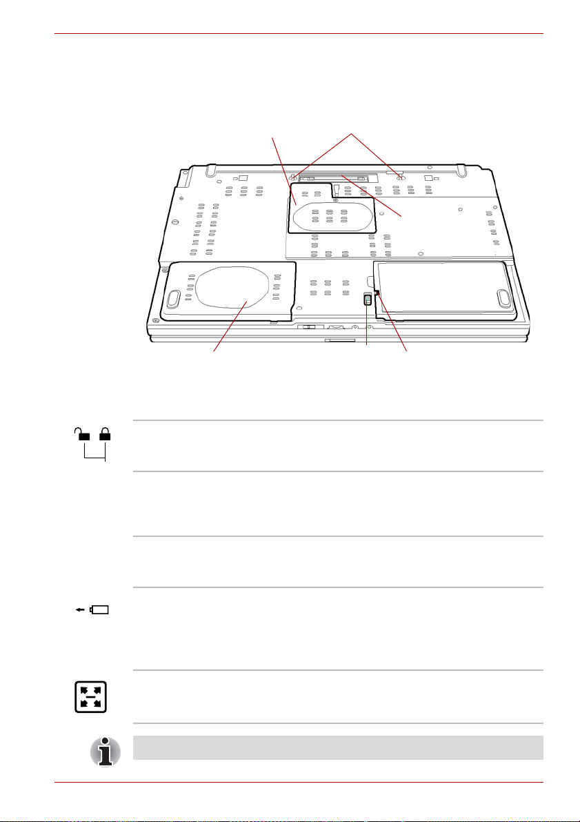
Underside
Figure 2-5 shows the underside of the computer. Make sure the display is
closed before turning over your computer.
Memory module cover
The Grand Tour
Notches
Docking port
Battery pack
HDD pack cover
Battery release latch
Figure 2-5 The underside of the computer
Battery lock
Battery lock Slide the battery lock to release the battery pack
for removal.
Battery pack The battery pack powers the computer when the
AC adaptor is not connected. For detailed
information on the battery pack, refer to
Chapter 6, Power and Power-Up Modes.
Notches Notches on the computer engage hooks on the
Advanced Port Replicator III Plus to ensure a
secure connection.
Battery release latch Slide and hold this latch to release the battery
pack for removal.
For detailed information on removing the battery
pack, refer to Chapter 6, Power and Power-Up
Modes.
Docking port This port enables connection of an optional
Advanced Port Replicator III Plus described in
Chapter 8, Optional Devices.
Depending on the model, a docking port is not present.
User’s Manual 2-7
Page 40

The Grand Tour
■ Only the Advanced Port Replicator III plus can be used with this
computer. Do not attempt to use any other Port Replicator.
■ Keep foreign objects out of the docking port. A pin or similar object can
damage the computer’s circuitry. A plastic shutter protects the
connector.
Memory module
cover
This cover protects memory module sockets.
Refer to the Memory expansion section in
Chapter 8, Optional Devices.
HDD pack cover The built-in HDD is under this cover.
Front with the display open
This section shows the computer with the LCD display panel open. Refer to
the appropriate illustration for details. To open the LCD display panel, slide
the display latch on the front of the LCD display panel and lift up. Position
the LCD display panel at a comfortable viewing angle.
Display hinge
LCD Sensor switch
(Not shown)
LCD screen
Stereo speaker (Right)
Touch Pad
Stereo speaker
(Left)
Power button
TOSHIBA Assist
Figure 2-6 The front of the computer with the LCD display panel open
2-8 User’s Manual
button
TOSHIBA Presentation button
Touch Pad
control buttons
Page 41

The Grand Tour
Display hinge The display hinge holds the LCD display panel at
easy-to-view angles.
LCD screen The LCD screen displays high-contrast text and
graphics. You can change the resolution between
800 x 600 and 1,280 x 800 pixels. Refer to
Display Controller and Modes section in
Appendix B.
When the computer operates on the AC adaptor
the LCD screen’s image will be somewhat
brighter than when it operates on battery power.
The lower brightness level is intended to save
battery power.
Stereo speakers The speakers emit sound generated by your
software as well as audio alarms, such as low
battery condition, generated by the system.
Touch Pad control
buttons
Control buttons below the Touch Pad let you
select menu items or manipulate text and
graphics designated by the on-screen pointer.
Touch Pad A Touch Pad located in the center of the palm
rest is used to control the on-screen pointer.
Refer to the Using the Touch Pad section in
Chapter 4, Operating Basics.
TOSHIBA
Presentation button
Press this button to display the same image on
both internal and external monitors or to use
multi-monitor display (Windows XP Only).
The default setting is “Presentation (Same Image
1,024 × 768)”. The same image is displayed on
the internal and external monitor with screen
resolution 1,024 × 768.
In the setting of “Presentation (Different Image)”,
you can use the internal and external monitors as
a widescreen.
This setting is supported in Windows XP only.
Pressing the button again can be changed single
display mode on an internal monitor only.
You can specify the function of TOSHIBA
Presentation button in the TOSHIBA Controls
properties.
Depending on the model, TOSHIBA Presentation
button is not present.
User’s Manual 2-9
Page 42

The Grand Tour
TOSHIBA Assist
button
Power button Press the power button to turn the computer’s
LCD Sensor switch This switch senses when the computer’s LCD
Do not put a magnetic object close to the switch. The computer will
automatically enter Hibernation Mode and shut down even if the Panel
Power Off feature is disabled.
Press this button to launch the program. The
default is TOSHIBA Assist.
When the computer is in Standby or Hibernation
Mode or turned off, press this button to start the
computer and launch the program.
You can specify the function of TOSHIBA Assist
button in the TOSHIBA Controls properties.
Depending on the model, TOSHIBA Assist button
is not present.
power on and off.
display panel is closed or opened and activates
the Panel Power Off/On feature. When you close
the LCD display panel the computer enters
Hibernation Mode and shuts down. When you
open the computer’s LCD display panel the
computer starts in Hibernation Mode. Use the
TOSHIBA Power Saver Utility to enable or
disable this feature. The default is “enabled”.
Refer to the TOSHIBA Power Saver Utility and
Panel Power Off/On items in Chapter 1, Special
features, for details on settings.
System indicators
LEDs at the left side of the icons, light when various computer operations
are in progress.
Figure 2-7 System indicators
SD card The SD card indicator glows green when the
computer is accessing the SD card slot.
DC IN The DC IN indicator glows green when DC power
2-10 User’s Manual
is supplied from the AC power adaptor. If the
adaptor’s output voltage is abnormal or if the
power supply malfunctions, this indicator flashes
orange.
Page 43

The Grand Tour
Power The Power indicator glows green when the
computer is on. If you select Standby from Shut
Down Windows, this indicator flashes (one
second on, two seconds off) while the computer
shuts down.
Battery The Battery indicator shows the condition of the
battery’s charge: Green indicates full charge,
orange indicates battery charging and flashing
orange indicates a low battery charge. Refer to
Chapter 6, Power and Power-Up Modes.
HDD The HDD indicator glows green when the
computer is accessing the built-in hard disk drive.
Wireless
communication
Keyboard indicators
The figures below show the positions of the keypad overlay indicators and
the Caps Lock indicator.
When the Arrow mode indicator glows the keypad overlay lets you control
the cursor.
When the Numeric mode indicator glows the keypad overlay lets you enter
numbers.
When the Caps Lock indicator glows the keyboard is in all-caps mode.
The Wireless communication indicator glows
when the Bluetooth and wireless LAN functions
are turned on.
All models are provided with a Wireless
Communication switch although only some
models are equipped with both Wireless LAN
and Bluetooth functions.
Caps Lock indicator
Figure 2-8 Caps Lock indicator
Caps Lock This indicator glows green when the alphabet
keys are locked in uppercase.
User’s Manual 2-11
Page 44

The Grand Tour
Arrow mode
Arrow mode When the Arrow mode indicator lights green,
Numeric mode You can use the keypad overlay (gray labeled
USB floppy disk drive
The USB floppy disk drive accommodates 1.44-megabyte or 720-kilobyte
floppy disk and connects to the USB port. It is supplied as standard with
some models and as an option with others.
Numeric
mode
Figure 2-9 Keypad overlay indicators
you can use the keypad overlay (gray labelled
keys) as cursor keys. Refer to the Keypad
overlay section in Chapter 5, The Keyboard.
keys) for numeric input when the Numeric mode
indicator lights green. Refer to the Keypad
overlay section in Chapter 5, The Keyboard.
USB connector
Disk-In-Use
Indicator
Floppy disk slot
Figure 2-10 USB floppy disk drive
Eject button
USB connector Insert this connector into one of the USB ports of
your computer.
Disk-In-Use Indicator This indicator lights when the floppy disk is being
accessed.
2-12 User’s Manual
Page 45

Floppy disk slot Insert a floppy disk in this slot.
Eject button When a floppy disk is fully seated in the drive, the
Check the Disk-In-Use indicator when you use the USB floppy disk drive.
Do not press the eject button or turn off the computer while the light is
glowing. Doing so could destroy data and damage the floppy disk or the
drive.
■ The USB floppy disk drive should be placed on a flat, horizontal surface
when in use. Do not set the drive on an incline 20° while it is operating.
■ Do not set anything on top of the floppy disk drive.
Optical disk drives
One of the following Optical disk drives is installed in the computer:
CD-ROM, DVD-ROM, DVD-ROM&CD-R/RW and DVD Super Multi drives.
An ATAPI interface controller is used for CD/DVD-ROM operation. When
the computer is accessing a CD/DVD, an indicator on the drive glows.
For information on loading and unloading discs refer to the Using optical
disk drives section in Chapter 4, Operating Basics.
The Grand Tour
eject button pops out. To remove a floppy disk,
push in the eject button and the floppy disk pops
out partially for removal.
Region codes for DVD drives and media
DVD-ROM&CD-R/RW, DVD Super Multi drives and their associated media
are manufactured according to the specifications of six marketing regions.
When you purchase DVD-Video, make sure it matches your drive,
otherwise it will not play properly.
Code Region
1 Canada, United States
2 Japan, Europe, South Africa, Middle East
3 Southeast Asia, East Asia
4 Australia, New Zealand, Pacific Islands, Central America,
South America, Caribbean
5 Russia, Indian Subcontinent, Africa, North Korea, Mongolia
6 China
User’s Manual 2-13
Page 46

The Grand Tour
Writable discs
CDs
DVDs
Formats
This section describes the types of writable CD/DVD discs. Check the
specifications for your drive for the type of discs it can write. Use
RecordNow! to write compact discs. Refer to Chapter 4, Operating Basics.
■ CD-R discs can be written only once. The recorded data cannot be
erased or changed.
■ CD-RW discs including multi speed CD-RW discs, high-speed CD-RW
discs and ultra-speed CD-RW discs can be recorded more than once.
■ DVD-R, DVD+R, DVD-R DL and DVD+R DL discs can be written only
once. The recorded data cannot be erased or changed.
■ DVD-RW, DVD+RW and DVD-RAM discs can be recorded more than
once.
The drives support the following formats:
■ CD-ROM
■ DVD-ROM
■ CD-DA
■ Photo CD™
(single/multi-session)
■ CD-ROM XA Mode 2
(Form1, Form2)
■ DVD -Video
■ CD-Text
■ CD-ROM Mode 1, Mode 2
■ Enhanced CD (CD-EXTRA)
■ Addressing Method 2
CD-ROM drive
The full-size CD-ROM drive module lets you run either 12 cm (4.72") or
8 cm (3.15") CD without using an adaptor.
The read speed is slower at the center of a disc and faster at the outer
edge.
CD read 24 speed (maximum)
DVD-ROM drive
The full-size DVD-ROM drive module lets you run either 12 cm (4.72") or
8 cm (3.15") CD/DVDs without using an adaptor.
The read speed is slower at the center of a disc and faster at the outer
edge.
DVD read 8 speed (maximum)
CD read 24 speed (maximum)
2-14 User’s Manual
Page 47

DVD-ROM&CD-R/RW drive
The full-size DVD-ROM&CD-R/RW drive module lets you record data to
rewritable CDs as well as run either 12 cm (4.72") or 8 cm (3.15") CD/DVDs
without using an adaptor.
The read speed is slower at the center of a disc and faster at the outer
edge.
DVD read 8 speed (maximum)
CD read 24 speed (maximum)
CD-R write 24 speed (maximum)
CD-RW write 24 speed (maximum, Ultra speed media)
DVD Super Multi drive
The full-size DVD Super Multi drive module lets you record data to
rewritable CDs as well as run either 12 cm (4.72") or 8 cm (3.15") CD/DVDs
without using an adaptor.
■ The read speed is slower at the center of a disc and faster at the outer
edge.
DVD read 8 speed (maximum)
DVD-R write 8 speed (maximum)
DVD-RW write 4 speed (maximum)
DVD-R DL write 2 speed (maximum)
DVD+R write 8 speed (maximum)
DVD+R DL write 2.4 speed (maximum)
DVD+RW write 4 speed (maximum)
DVD-RAM write 5 speed (maximum)
CD read 24 speed (maximum)
CD-R write 24 speed (maximum)
CD-RW write 10 speed (maximum, Ultra-speed media)
2.6GB and 5.2GB DVD-RAM media cannot be read from or written to.
The Grand Tour
User’s Manual 2-15
Page 48

The Grand Tour
AC adaptor
The AC adaptor can automatically adjust to any voltage ranging from 100 to
240 volts and to a frequency of either 50 or 60 hertz, enabling you to use
this computer in almost any country/region. The adaptor converts AC
power to DC power and reduces the voltage supplied to this computer.
To recharge the battery, simply connect the AC adaptor to a power source
and the computer. Refer to Chapter 6, Power and Power-Up Modes for
details.
Figure 2-11 The AC adaptor (2-pin plug)
Figure 2-12 The AC adaptor (3-pin plug)
■ Depending on the model, a 2-pin or 3-pin plug set of the above may be
bundled.
■ Do not use a 3-pin to 2-pin conversion plug.
■ The supplied power cord conforms to safety rules and regulations in
the region the product is bought and should not be used outside this
region. For use in other regions, please buy power cords that conform
to safety rules and regulations in the particular region.
Always use the TOSHIBA AC adaptor that was provided with your PC and
the TOSHIBA Battery Charger (that may have been provided with your
PC), or use AC adaptors and battery chargers specified by TOSHIBA to
avoid any risk of fire or other damage to the PC. Use of an incompatible
AC adaptor or Battery Charger could cause fire or damage to the PC
possibly resulting in serious injury.
2-16 User’s Manual
Page 49

Getting Started
This chapter provides basic information to get you started using your
computer. It covers the following topics:
■ Connecting the AC adaptor
■ Opening the display
■ Turning on the power
■ Starting up for the first time
■ Turning off the power
■ Restarting the computer
■ Creating recovery media
■ Restoring the preinstalled software from the Hard Disk Drive (HDD)
■ Restoring the preinstalled software from the Recovery Media
All users should be sure to read the section Starting up for the first time.
Chapter 3
Be sure to read the Instruction manual for Safety and Comfort to become
more comfortable and productive while using a notebook computer. By
following the recommendations in this guide you may reduce your chance
of developing a painful or disabling injury to your hand, arms, shoulders or
neck.
User’s Manual 3-1
Page 50

Getting Started
Other Things to Note
■ Use a virus-check program and make sure it is updated regularly.
■ Never format storage media without checking its content. Formatting
destroys all stored data.
■ It is a good idea to periodically back up the internal hard disk or other
main storage device to external media. General storage media is not
durable or stable over long periods of time and under certain conditions
may result in data loss.
■ Before you install a device or application, save any data in memory to
the hard disk drive or other storage media. Failure to do so may result
in the loss of data.
Connecting the AC adaptor
Attach the AC adaptor when you need to charge the battery or you want to
operate from AC power. It is also the fastest way to get started, because
the battery pack will need to be charged before you can operate from
battery power.
The AC adaptor can be connected to any power source supplying from 100
to 240 volts and 50 or 60 hertz. For details on using the AC adaptor to
charge the battery pack, refer to Chapter 6, Power and Power-Up Modes.
■ Always use the Toshiba AC adaptor that was provided with your PC
and the Toshiba Battery Charger (that may have been provided with
your PC), or use Toshiba recommended alternate models to avoid any
risk of fire or other damage to the PC. Use of an incompatible AC
adaptor or Battery Charger could cause fire or damage to the PC
possibly resulting in serious injury.
■ Use only the AC adaptor supplied with your computer or an equivalent
adaptor that is compatible. Use of any incompatible adaptor could
damage your computer. TOSHIBA assumes no liability for any damage
caused by use of an incompatible adaptor.
■ Never plug the AC adaptor or Battery Charger into a power source that
does not correspond to both the voltage and the frequency specified on
the regulatory label of the unit. Failure to do so could result in a fire or
electric shock, possibly resulting in serious injury.
■ Always use or purchase power cables that comply with the legal
voltage and frequency specifications and requirements in the country of
use. Failure to do so could result in a fire or electric shock, possibly
resulting in serious injury.
3-2 User’s Manual
Page 51

Getting Started
■ The supplied power cord conforms to safety rules and regulations in
the region the product is bought and should not be used outside this
region. For use in other regions, please buy power cords that conform
to safety rules and regulations in the particular region.
■ Do not use a 3-pin to 2-pin conversion plug.
■ When you connect the AC adaptor to the computer, always follow the
steps in the exact order as described in the User’s Manual. Connecting
the power cable to a live electrical outlet should be the last step
otherwise the adaptor DC output plug could hold an electrical change
and cause an electrical shock or minor bodily injury when touched. As
a general safety precaution, avoid touching any metal parts.
■ Never place your PC or AC adaptor on a wooden surface, furniture, or
any other surface that could be marred by exposure to heat since the
PC base and AC adaptor’s surface increase in temperature during
normal use.
■ Always place your PC or AC adaptor on a flat and hard surface that is
resistant to heat damage.
1. Connect the power cord to the AC adaptor.
Figure 3-2 Connecting the power cord to the AC adaptor (2-pin plug)
Figure 3-3 Connecting the power cord to the AC adaptor (3-pin plug)
Depending on the model, a 2-pin plug or 3-pin plug set of the above may
be bundled.
User’s Manual 3-3
Page 52

Getting Started
2. Connect the AC adaptor’s DC output plug to the DC IN 15V jack on the
back of the computer.
Figure 3-4 Connecting the adaptor to the computer
3. Plug the power cord into a live wall outlet. The Battery and DC IN
indicators on the front of the computer should glow.
Opening the display
The computer’s LCD display panel can be opened in a wide range of
angles for optimal viewing.
1. Slide the display latch on the front of the computer to unlatch the
display panel.
2. While holding down the palm rest with one hand so that the main body
is not raised, lift the panel slowly. Adjust the angle of the panel to
provide optimal clarity.
DC IN jack
AC adaptor’s DC
output plug
Use reasonable care when opening and closing the LCD display panel.
Opening it vigorously or slamming it shut could damage the computer.
LCD display panel
Figure 3-5 Opening the LCD display panel
3-4 User’s Manual
Display latch
Page 53

Turning on the power
This section describes how to turn on the power.
The Power button LED indicates the status. Refer to the Power indicators
section in Chapter 6, Power and Power-Up Modes.
■ After you turn on the power for the first time, do not turn it off until you
have set up the operating system. Refer to the section Starting up for
the first time.
■ If the USB floppy disk drive is connected, make sure it is empty. If a
floppy disk is in the drive, press the eject button and remove the floppy
disk.
1. Open the computer’s LCD display panel.
2. Press and hold the computer’s power button for two or three seconds.
Power button
Getting Started
Figure 3-6 Turning on the power
Starting up for the first time
When you first turn on the power, the computer’s initial screen is the
Microsoft Windows XP Startup Screen Logo. Follow the on-screen
directions for each screen. During setup, you can click the Back button to
return to the previous screen.
Be sure to read the Windows End User License Agreement display
carefully.
User’s Manual 3-5
Page 54

Getting Started
Turning off the power
The power can be turned off in one of the following modes: Shut down
(Boot), Hibernation or Standby Mode.
Shut Down mode (Boot mode)
When you turn off the power in Shut Down mode no data is saved and the
computer will boot to the operating system’s main screen.
1. If you have entered data, save it to the hard disk or to a storage media.
2. Make sure all disk (disc) activity has stopped, then remove the
CD/DVDs or floppy disk.
■ Make sure the Hard Disk Drive (HDD) is off. If you turn off the power
while a disk (disc) is being accessed, you can lose data or damage the
disk (disc).
■ Never turn off the power while an application is running. Doing so could
cause loss of data.
■ Never turn off the power, disconnect an external storage device or
remove storage media during data read/write. Doing so can cause data
loss.
3. Click start then click Turn Off Computer. From the Turn Off
Computer menu select Turn Off.
4. Turn off the power to any peripheral devices.
Do not turn the computer or devices back on immediately. Wait a moment
to let all capacitors fully discharge.
Standby Mode
If you have to interrupt your work, you can turn off the power without exiting
from your software. Data is maintained in the computer’s main memory.
When you turn on the power again, you can continue working right where
you left off.
■ When the AC adaptor is connected, the computer will go into Standby
Mode according to the settings in the TOSHIBA Power Saver utility.
■ To restore operation from Standby Mode, press the power button or
press any key. The latter action only works on the internal keyboard if
the Wake-up on Keyboard option is enabled in HW Setup.
■ If the computer automatically enters Standby Mode while a network
application is active, the application might not be restored when the
computer wakes up from Standby.
■ To prevent the computer from automatically entering Standby Mode,
disable Standby in TOSHIBA Power Saver. That action, however, will
nullify the computer’s Energy Star compliance.
3-6 User’s Manual
Page 55

Getting Started
■ Before entering Standby Mode, be sure to save your data.
■ Do not install or remove a memory module while the computer is in
Standby Mode. The computer or the module could be damaged.
■ Do not remove the battery pack while the computer is in Standby Mode
(unless the computer is connected to an AC power source). Data in
memory will be lost.
■ If you carry the computer on board an aircraft or into a hospital, be sure
to shut down the computer in Hibernation Mode or in shutdown mode
to avoid radio signal interference.
Benefits of standby
The standby feature provides the following benefits:
■ Restores the previous working environment more rapidly than does
hibernation.
■ Saves power by shutting down the system when the computer receives
no input or hardware access for the duration set by the System Standby
feature.
■ You can use the panel power off feature.
Executing standby
You can also enable Standby by pressing Fn + F3. See Chapter 5, The
Keyboard, for details.
You can enter Standby Mode in one of three ways:
1. Click start, click Turn Off Computer and click Stand By.
2. Close the computer’s LCD display panel. This feature must be enabled.
Refer to the Setup Actions tab in TOSHIBA Power Saver Utility
described in the Control Panel.
Open Performance and Maintenance and open TOSHIBA Power
Saver.
3. Press the power button. This feature must be enabled. Refer to the
Setup Actions tab in TOSHIBA Power Saver Utility described in the
Control Panel.
Open Performance and Maintenance and open TOSHIBA Power
Saver.
When you turn the power back on, you can continue where you left when
you shut down the computer.
■ When the computer is shut down in Standby Mode, the power indicator
blinking orange.
■ If you are operating the computer on battery power, you can lengthen
the operating time by shutting down in Hibernation Mode. Standby
Mode consumes more power.
User’s Manual 3-7
Page 56

Getting Started
Standby limitations
Standby will not function under the following conditions:
■ Power is turned back on immediately after shutting down.
■ Memory circuits are exposed to static electricity or electrical noise.
Hibernation Mode
The Hibernation Mode feature saves the contents of memory to the hard
disk when the computer is turned off. The next time the computer is turned
on, the previous state is restored. The Hibernation Mode feature does not
save the status of any peripheral devices.
■ Save your data. While entering Hibernation Mode, the computer saves
■ Data will be lost if you remove the battery or disconnect the AC adaptor
■ Do not install or remove a memory module while the computer is in
Benefits of Hibernation Mode
The Hibernation Mode feature provides the following benefits:
■ Saves data to the hard disk when the computer automatically shuts
the contents of memory to the hard disk drive. However, for safety
sake, it is best to save your data manually.
before the save is completed. Wait for the HDD indicator to go out.
Hibernation Mode. Data will be lost.
down because of a low battery.
For the computer to shut down in Hibernation Mode, this feature must be
enabled in two places: the Hibernate tab in Power Options and Setup
Actions tab in TOSHIBA Power Saver.
If you do not configure this feature, the computer will shut down in Standby
Mode - if battery power becomes depleted, data saved in Standby Mode
will be lost.
■ You can return to your previous working environment immediately when
you turn on the computer.
■ Saves power by shutting down the system when the computer receives
no input or hardware access for the duration set by the System
hibernate feature.
■ You can use the panel power off feature.
3-8 User’s Manual
Page 57

Getting Started
Starting Hibernation Mode
You can also enable Hibernation Mode by pressing Fn + F4. Refer to
Chapter 5, The Keyboard, for details.
To enter Hibernation Mode, follow the steps below.
1. Click start.
2. Select Turn Off Computer.
3. Open the Turn Off Computer dialog box.
4. Click Hibernate.
Automatic Hibernation
The computer will enter Hibernate mode automatically when you press the
power button or close the lid. First, however, make the appropriate settings
according to the steps below.
1. Click start and open the Control Panel.
2. Open Performance and Maintenance and open Power Options.
3. Select the Hibernate window in the Power Options Properties,
select the Enable hibernation check box and click the Apply button.
4. Open TOSHIBA Power Saver.
5. Select the Setup Action window.
6. Enable the desired Hibernation settings for When I press the power
button and When I close the lid.
7. Click the OK button.
Data save in Hibernation Mode
When you turn off the power in Hibernation Mode, the computer takes a
moment to save current memory data to the hard disk. During this time, the
HDD indicator will light.
After you turn off the computer, and the content of memory has been saved
to the hard disk, turn off the power to any peripheral devices.
Do not turn the computer or devices back on immediately. Wait a moment
to let all capacitors fully discharge.
User’s Manual 3-9
Page 58

Getting Started
Restarting the computer
Certain conditions require that you reset the system. For example, if:
■ You change certain computer settings.
■ An error occurs and the computer does not respond to your keyboard
commands.
■ There are three ways to reset the computer system:
1. Click start then click Turn off computer. From the Turn off
computer menu select Restart.
2. Press Ctrl + Alt + Del to display the Windows Task Manager,
then select Shut Down and Restart.
3. Press the power button and hold it down for five seconds. Wait 10 to
15 seconds, then turn the power on again by pressing the power
button.
Restoring the preinstalled software from the Product Recovery Media
If preinstalled files are damaged, use the Product Recovery Media to
restore them. To restore the operating system and all preinstalled software,
follow the steps below.
When you reinstall the Windows operating system, the hard disk will be
reformatted and all data will be lost.
1. Load the Recovery Media in the optional optical media drive and turn off
the computer’s power.
2. Hold down the F12 key and turn on the power. When In Touch with
Tomorrow TOSHIBA appears, release the F12 key.
3. Use the cursor key to select the CD/DVD icon in the display menu. For
details, refer to the Boot Priority section in Chapter 7, HW Setup.
4. Follow the on-screen instructions.
5. If your computer came with additional software installed, this software
can not be recovered from the Product Recovery disk. Re-install these
applications (e.g. Works Suite, DVD Player, Games, etc.) separately
from other media.
Restoring TOSHIBA utilities and drivers
If Windows is working properly, individual drivers or applications can be
separately restored. The TOSHIBA Tools & Utilities folder (C:\TOOLSCD)
contains drivers and applications, which are included with your computer
system. If your system drivers or applications have become damaged in
some way, you can reinstall most of the components from this folder.
Create a copy of this folder to an external media for more convenience.
3-10 User’s Manual
Page 59

Operating Basics
This chapter describes the basic operations of your computer and
precautions when using it, as well as the handling of CD/DVD.
Using the Touch Pad
To use the Touch Pad, simply touch and move your fingertip across it in the
direction you want the on-screen pointer to go.
Chapter 4
Touch Pad
Touch Pad
Figure 4-1 Touch Pad and Touch Pad control buttons
Two buttons below the Touch Pad are used like the buttons on a mouse
pointer. Press the left button to select a menu item or to manipulate text or
graphics designated by the pointer. Press the right button to display a menu
or other function depending on the software you are using.
User’s Manual 4-1
control buttons
Page 60

Operating Basics
You can also tap the Touch Pad to perform functions similar to those of the
left button.
Click: Tap once
Double-click: Tap twice
Drag and drop: Tap to select the material you want to move. Leave
your finger on the Touch Pad after the second tap and move the
material.
Using the USB floppy disk drive
The USB floppy disk drive accommodates 1.44-megabyte or 720-kilobyte
floppy disk and connects to the USB port. Refer to Chapter 2, The Grand
Tou r, for more information. It is supplied as standard with some models and
as an option with others.
Connecting USB floppy disk drive
To connect the drive, plug the floppy disk drive’s USB connector into a
computer’s USB port. Refer to Figure 4-3.
Make sure the connector is right side up and properly aligned with the
socket. Do not try to force the connection, doing so can damage the
connecting pins.
USB port
USB connector
Figure 4-3 Connecting the USB floppy disk drive
If you connect the USB floppy disk drive after turning on the computer, it
will take about 10 seconds for the computer to recognize the drive. Do not
disconnect and reconnect before 10 seconds has elapsed.
4-2 User’s Manual
Page 61

Disconnecting USB floppy disk drive
When you have finished using the USB floppy disk drive, follow the
procedures below to disconnect it:
1. Wait for the indicator light to go out to make sure all floppy disk activity
has stopped.
If you disconnect the USB floppy disk drive or turn off the power while the
computer is accessing the drive you may lose data or damage the floppy
disk or the drive.
2. Click the Safely Remove Hardware icon on the Task Bar.
3. Click USB floppy disk drive device that you want remove.
4. Pull the floppy disk drive’s USB connector out of the computer’s USB
port.
Using optical disk drives
The text and illustrations in this section refer primarily to the optical disk
drive.The full-size drive provides high-performance execution of
CD/DVD-ROM-based programs. You can run either 12 cm (4.72") or 8 cm
(3.15") CD/DVDs without an adaptor. An ATAPI interface controller is used
for CD/DVD-ROM operation. When the computer is accessing a
CD/DVD-ROM, an indicator on the drive glows.
Use the WinDVD application to view DVD-Video discs.
Operating Basics
If you have a DVD-ROM&CD-R/RW drive, refer also to the Writing CDs on
DVD-ROM&CD-R/RW drive section for precautions on writing to CDs.
If you have a DVD Super Multi drive, refer also to the Writing CD/DVDs on
DVD Super Multi drive section for precautions on writing to CDs/DVDs.
Loading discs
To load CD/DVDs, follow the steps below and refer to figures 4-4 to 4-7.
1. When the computer’s power is on, press the eject button to open
the disc tray slightly.
Eject button
Figure 4-4 Pressing the eject button
User’s Manual 4-3
Page 62

Operating Basics
2. Grasp the disc tray gently and pull until it is fully opened.
Disc tray
Figure 4-5 Pulling the disc tray open
3. Lay the CD/DVD, label side up, in the disc tray.
Laser lens
Figure 4-6 Inserting a CD/DVD
When the disc tray is fully opened, the edge of the computer will extend
slightly over the CD/DVD tray. Therefore, you will need to turn the CD/DVD
at an angle when you place it in the disc tray. After seating the CD/DVD,
however, make sure it lies flat, as shown in figure 4-5.
■ Do not touch a laser lens and its circumference portion. Doing so could
cause misalignment.
■ Prevent foreign objects from entering the drive. Check the surface of
the disc tray, especially the area behind the front edge of the disc tray,
to make sure there are no such objects before closing the drive.
4. Press gently at the center of the CD/DVD until you feel it click into
place. The CD/DVD should lie below the top of the spindle, flush with
the spindle base.
4-4 User’s Manual
Page 63

5. Push the center of the disc tray to close it. Press gently until it locks into
place.
If the CD/DVD is not seated properly when the disc tray is closed, the
CD/DVD might be damaged. Also, the disc tray might not open fully when
you press the eject button.
Figure 4-7 Closing the CD/DVD disc tray
Removing discs
To remove the CD/DVD, follow the steps below and refer to figure 4-10.
Do not press the eject button while the computer is accessing the media
drive. Wait for the optical disk indicator to go out before you open the disc
tray. Also, if the CD/DVD is spinning when you open the disc tray, wait for it
to stop before you remove it
.
Operating Basics
1. To pop the disc tray partially open, press the eject button. Gently pull
the disc tray out until it is fully opened.
When the disc tray pops open slightly, wait a moment to make sure the
CD/DVD has stopped spinning before pulling the disc tray fully open.
2. The CD/DVD extends slightly over the sides of the disc tray so you can
hold it. Hold the CD/DVD gently and lift it out.
Figure 4-8 Removing a CD/DVD
User’s Manual 4-5
Page 64

Operating Basics
3. Push the center of the disc tray to close it. Press gently until it locks into
place.
How to remove CD/DVD when the disc tray will not open
Pressing the eject button will not open the disc tray when the computer
power is off. If the power is off, you can open the disc tray by inserting a
slender object (about 15 mm) such as a straightened paper clip into the
eject hole just to the right of the eject button.
15mm
Eject hole
Figure 4-9 Manual release with the eject hole
Turn off the power before you use the eject hole. If the CD/DVD is spinning
when you open the disc tray, the CD/DVD could fly off the spindle and
cause injury.
Writing CDs on DVD-ROM&CD-R/RW drive
Depending on the type of drive installed, you may be able to write CDs. The
DVD-ROM&CD-R/RW drive lets you write as well as read CD-ROMs.
Observe the precautions in this section to ensure the best performance for
writing CDs. For information on loading and unloading CDs refer to the
Using optical disk drives section.
■ Refer to the Writable discs, Chapter 2 for details about the types of
writable CD/DVD discs.
When writing to media using an optical drive, always connect the AC
adaptor to a power plug socket or power source to ensure maximum
performance. If data is written powered by the batteries, writing may
sometimes fail due to low battery power and data loss may occur.
4-6 User’s Manual
Page 65

Before writing or rewriting
Please observe the following points when you write or rewrite the data.
■ We recommend the following manufacturers of CD-R and CD-RW
media. Media quality can affect write or rewrite success rates.
CD-R:
TAIYO YUDEN CO., LTD.
MITSUBISHI CHEMICAL CORPORATION
RICOH Co., Ltd.
Multi-Speed and High-Speed CD-RW:
MITSUBISHI CHEMICAL CORPORATION
RICOH Co., Ltd.
Ultra-Speed CD-RW:
MITSUBISHI CHEMICAL CORPORATION
TOSHIBA has confirmed the operation of CD-R and CD-RW media of the
manufacturers above. Operation of other media cannot be guaranteed.
■ The actual number of rewrites to CD-RW is affected by the quality of the
disc and the way it is used.
■ Be sure to connect the AC adaptor when you write or rewrite.
■ Be sure to close all other software programs except the writing
software.
■ Do not run software such as a screen saver which can put a heavy load
on the CPU.
■ Operate the computer at full power. Do not use power-saving features.
■ Do not write while virus check software is running. Wait for it to finish,
then disable virus detection programs including any software that
checks files automatically in the background.
■ Do not use hard disk utilities, including those intended to enhance hard
disk drive access speeds. They may cause unstable operation and
damage data.
■ Write from the computer’s hard disk drive to the CD. Do not try to write
from shared devices such as a LAN server or any other network device.
■ Writing with software other than Sonic RecordNow! has not been
confirmed. Therefore, operation with other software cannot be
guaranteed.
Operating Basics
User’s Manual 4-7
Page 66

Operating Basics
When writing or rewriting
Note the following when you write or rewrite a CD-R or CD-RW.
■ Always copy data from the hard disk drive to the optical media. Do not
use cut-and-paste as the original data will be lost if there is a write error.
■ Do not perform any of the following actions:
■ Change users in the Windows XP operating system.
■ Operate the computer for any other function, including use of a
mouse or Touch Pad, closing/opening the LCD panel.
■ Start a communication application such as a modem.
■ Apply impact or vibration to the computer.
■ Install, remove or connect external devices, including the following:
PC card, SD card, USB devices, external monitor, i.LINK devices,
optical digital devices.
■ Open the optical disk drive.
■ Make sure writing or rewriting is completed before going into
standby/hibernation. Writing is completed if you can open the CDs on
DVD-ROM&CD-R/RW drive tray.
■ If the media is poor in quality, dirty or damaged, writing or rewriting
errors may occur.
■ Set the computer on a level surface and avoid places subject to
vibration such as airplanes, trains or cars. Do not use an unstable
surface such as a stand.
■ Keep mobile phones and other wireless communication devices away
from the computer.
Writing CD/DVDs on DVD Super Multi drive
You can use the DVD Super Multi drive to write data to either CD-R/RW or
DVD-R/-R DL/-RW/+R/+R DL/+RW/-RAM discs. The following applications
for writing are provided: RecordNow!, and DLA licensed by Sonic
Solutions, and InterVideo’s WinDVD Creator Platinum.
■ Refer to the Writable discs, Chapter 2 for details about the types of
writable CD/DVD discs.
When writing to media using an optical drive, always connect the AC
adaptor to a power plug socket or power source to ensure maximum
performance. If data is written powered by the batteries, writing may
sometimes fail due to low battery power and data loss may occur.
4-8 User’s Manual
Page 67

Important message
Before you write or rewrite to CD-R/RW or
DVD-R/-R DL/-RW/+R/+R DL/+RW/-RAM discs, read and follow all setup
and operating instructions in this section. If you fail to do so, the DVD Super
Multi drive may not function properly, and you may fail to write or rewrite,
lose data or incur other damage.
Disclaimers
TOSHIBA does not bear responsibility for the following:
■ Damage to any CD-R/RW or DVD-R/-R DL/-RW/+R/+R DL/+RW/-RAM
disc that may be caused by writing or rewriting with this product.
■ Any change or loss of the recorded contents of CD-R/RW or
DVD-R/-R DL/-RW/+R/+R DL/+RW/-RAM disc that may be caused by
writing or rewriting with this product, or for any business profit loss or
business interruption that may be caused by the change or loss of the
recorded contents.
■ Damage that may be caused by using third party equipment or
software.
Given the technological limitations of current optical disc writing drives, you
may experience unexpected writing or rewriting errors due to disc quality or
problems with hardware devices. Also, it is a good idea to make two or
more copies of important data, in case of undesired change or loss of the
recorded contents.
Operating Basics
Before writing or rewriting
■ Based on TOSHIBA’s limited compatibility testing, we suggest the
following manufacturers of CD-R/RW or
DVD-R/-R DL/-RW/+R/+R DL/+RW/-RAM disc. However, in no event
does TOSHIBA guarantee the operation, quality or performance of any
disc. Disc quality can affect write or rewrite success rates.
CD-R:
TAIYO YUDEN CO., LTD.
MITSUBISHI CHEMICAL CORPORATION
RICOH Co., Ltd.
CD-RW: (Multi-Speed and High-Speed)
MITSUBISHI CHEMICAL CORPORATION
RICOH Co., Ltd.
CD-RW: (Ultra-Speed)
MITSUBISHI CHEMICAL CORPORATION
User’s Manual 4-9
Page 68

Operating Basics
DVD-R:
DVD Specifications for Recordable Disc for General Version 2.0
TAIYO YUDEN CO., LTD.
Matsushita Electric Industrial Co., Ltd.
DVD-R DL:
MITSUBISHI CHEMICAL CORPORATION.
DVD+R:
MITSUBISHI CHEMICAL CORPORATION
RICOH Co., Ltd.
DVD+R DL:
MITSUBISHI CHEMICAL CORPORATION
DVD-RW:
DVD Specifications for Recordable Disc for Version 1.1 or version
1.2
VICTOR COMPANY OF JAPAN.LIMITED
MITSUBISHI CHEMICAL CORPORATION
DVD+RW:
MITSUBISHI CHEMICAL CORPORATION
RICOH Co., Ltd.
DVD-RAM:
DVD Specifications for DVD-RAM Disc for Version 2.0, Version 2.1
or Version 2.2
Hitachi Maxell Ltd.
This drive cannot use discs that allow writing faster than16 speed
(DVD-R, DVD+R), 4 speed (DVD-RW, DVD+RW), 5 speed (DVD-RAM),
4 speed (DVD-R DL) and 8 speed (DVD+R DL).
■ If the disc is poor in quality, dirty or damaged, writing or rewriting errors
may occur. Be careful to check the disc for dirt or damage before you
use it.
■ The actual number of rewrites to CD-RW, DVD-RW, DVD+RW or
DVD-RAM is affected by the quality of the disc and the way it is used.
■ DISC created in DVD-R DL format4 (Layer Jump Recording) cannot be
read.
■ There are two types of DVD-R discs: authoring and general use discs.
Do not use authoring discs. Only general use discs can be written to by
a computer drive.
4-10 User’s Manual
Page 69

Operating Basics
■ You can use DVD-RAM discs that can be removed from a cartridge and
DVD-RAM discs designed without a cartridge.
■ Other DVD-ROM drives for computers or other DVD players may not be
able to read DVD-R/-R DL/-RW or DVD+R/+R DL/+RW discs.
■ Data written to a CD-R/DVD-R-R DL/DVD+R/+R DL disc cannot be
deleted either in whole or in part.
■ Data deleted (erased) from a CD-RW, DVD-RW, DVD+RW and
DVD-RAM disc cannot be recovered. Check the content of the disc
carefully before you delete it. If multiple drives that can write data to
discs are connected, be careful not to delete data from the wrong drive.
■ In writing to a DVD-R/-R DL/-RW, DVD+R/+R DL/+RW or DVD-RAM
disc, some disc space is required for file management, so you may not
be able to write the full capacity of the disc.
■ Since the disc is based on the DVD standard, it might be filled with
dummy data if the written data is less than about 1 GB. Even if you write
only a small amount of data, it might take time to fill in the dummy data.
■ DVD-RAM formatted by FAT32 cannot be read in Windows 2000
without DVD-RAM Driver Software.
■ When multiple drives that can write data to discs are connected, be
sure to connect the AC adaptor before you write or rewrite.
■ Before you enter standby/Hibernation Mode, be sure to finish
DVD-RAM writing. Writing is finished if you can eject DVD-RAM media.
■ Be sure to close all other software programs except the writing
software.
■ Do not run software such as a screen saver, which can put a heavy load
on the CPU.
■ Operate the computer in the full-power mode. Do not use power-saving
features. Be careful not to write to the wrong drive.
■ Do not write while virus check software is running. Wait for it to finish
and then disable virus detection programs including any software that
checks files automatically in the background.
■ Do not use hard disk utilities, including those intended to enhance hard
disk drive access speed. They may cause unstable operation and data
damage.
■ CD-RW (Ultra Speed +) media is not supported. If used, data may be
lost or damaged.
■ Write from the computer’s hard disk drive to the CD/DVD. Do not try to
write from shared devices such as a LAN server or any other network
device.
■ Writing with software other than RecordNow! and InterVideo WinDVD
Creator Platinum are not recommended.
User’s Manual 4-11
Page 70

Operating Basics
When writing or rewriting
Please observe/consider the following when you write or rewrite to a
CD-R/-RW, DVD-R/-R DL/-RW/-RAM or DVD+R/+R DL/+RW disc.
■ Do not perform any of the following actions when writing or rewriting:
■ Change users in the Windows XP operating system.
■ Operate the computer for any other function, including using a
mouse or Touch Pad or closing/opening the LCD panel.
■ Start a communication application such as a modem.
■ Apply impact or vibration to the computer.
■ Install, remove or connect external devices, including the following:
PC card, SD card, USB devices, external monitor, i.LINK devices,
optical digital devices.
■ Use the Audio/Video control button to reproduce music or voice.
■ Open the optical disk drive.
■ Do not use shut down/log off and standby/hibernation while writing or
rewriting.
■ Make sure writing or rewriting is completed before going into
standby/hibernation. Writing is completed if you can open the DVD
Super Multi drive tray.
■ Set the computer on a level surface and avoid places subject to
vibration such as airplanes, trains, or cars. Do not use an unstable
surface such as a stand.
■ Keep mobile phones and other wireless communication devices away
from the computer.
■ Always copy data from the hard disk drive to the optical media. Do not
use cut-and-paste. The original data will be lost if there is a write error.
DISC created in DVD-R DL format4 (Layer Jump Recording) cannot be
read.
RecordNow! Basic for TOSHIBA
Note the following limitations when you use RecordNow!:
■ DVD-Video cannot be created using RecordNow!.
■ DVD-Audio cannot be created using RecordNow!.
■ You cannot use RecordNow!’s “Audio CD for Car or Home CD Player”
function to record music to the DVD-R/-R DL/-RW or
DVD+R/+R DL/+RW discs.
■ Do not use the “Exact Copy” function of RecordNow! to copy
DVD-Video and DVD-ROM with copyright protection.
■ DVD-RAM disc cannot be backed up with the “Exact Copy” function of
RecordNow!.
■ You cannot back up a CD-ROM or CD-R/RW to DVD-R/-R DL/-RW or
DVD+R/+R DL/+RW using the “Exact Copy” function of RecordNow!.
4-12 User’s Manual
Page 71

Operating Basics
■ You cannot back up DVD-ROM, DVD-Video, DVD-R/-R DL/-RW or
DVD+R/+R DL/+RW to CD-R/RW using the “Exact Copy” function of
RecordNow!.
■ RecordNow! cannot record in packet format.
■ You might not be able to use the “Exact Copy” function of RecordNow!
to back up a DVD-R/-R DL/-RW or DVD+R/+R DL/+RW disc that was
made with other software on a different DVD-R/-R DL/-RW or
DVD+R/+R DL/+RW recorder.
■ If you add data to a DVD-R/-R DL and DVD+R/+R DL disc that you
have already recorded to, you might not be able to read the added data
under some circumstances. It cannot be read in 16-bit operating
systems, such as Windows 98SE and Windows Me. In Windows NT4,
you will need Service Pack 6 or later to read added data. In Windows
2000, you will need Service Pack 2 or later to read it. Some DVD-ROM
and DVD-ROM&CD-R/RW drives cannot read added data regardless of
the operating system.
■ RecordNow! does not support recording to DVD-RAM discs. To record
to a DVD-RAM, use Explorer or another utility.
■ When you back up a DVD disc, be sure the source drive supports
recording to DVD-R/-R DL/-RW or DVD+R/+R DL/+RW discs. If the
source drive does not support recording to DVD-R/-R DL/-RW or
DVD+R/+R DL/+RW discs, it might not be backed up correctly.
■ When you back up a DVD-R/-R DL, DVD-RW, DVD+R/+R DL or
DVD+RW, be sure to use the same type of disc.
■ You cannot partially delete any data written to a CD-RW, DVD-RW or
DVD+RW disc.
Data Verification
To verify that data is written or rewritten correctly, follow the steps below
before you write or rewrite a Data CD/DVD.
1. Click the Options button ( ) on the RecordNow! Console to open
the Options panels.
2. Select the Data in the left-side menu.
3. Mark the Verify data written to the disc after burning check box in the
Data Options.
4. Click the OK button.
User’s Manual 4-13
Page 72

Operating Basics
DLA for TOSHIBA
Note the following limitations when you use DLA:
■ This software supports only rewritable discs (DVD+RW, DVD-RW, and
■ DLA does not support formatting and writing to a DVD-RAM disc - these
■ Do not use any discs that have been formatted with packet writing
■ Do not use the cut-and-paste function for files and folders. A file or
■ When writing any setup files for an application to a disc formatted by
CD-RW). It does not support DVD+R/+R DL, DVD-R/-R DL, and CD-R
discs that are not rewritable.
functions are performed by DVD-RAM Driver Software. Even if the DLA
Format menu appears when inserting a DVD-RAM disc and
right-clicking the drive icon in Windows Explorer, you should use the
“DVDForm” command to format this disc. You can run“DVDForm” by
clicking the Start button on the taskbar to display the Start menu and
then selecting “All Programs”, “DVD-RAM”, “DVD-RAM Driver” and
“DVDForm” sequentially.
software other than DLA. Similarly, do not use any discs that have been
formatted with DLA with any packet writing software other than DLA.
When using a disc you are not familiar with, format it by selecting “Full
Format” before using it.
folder that has been cut may be lost if writing fails due to an error on the
disc.
DLA, and attempting to start Setup from this disc, an error may occur. In
this case, please copy the files to your hard disk and then run Setup
from there.
When using WinDVD Creator Platinum
You can record video back to your digital camcorder via i.LINK (IEEE1394)
using WinDVD Creator Platinum. However, there is a case where its
playback sound appears choppy - in this instance please follow the
instructions below:
1. Click start and select the Control Panel.
2. Click the Performance and Maintenance icon in the Control Panel.
3. Click the System icon in the Performance and Maintenance window.
4. Click the Advanced tab in the System Properties window.
5. Click the Settings icon in the “Performance” section.
6. Click the Advanced tab in the Performance Options window.
7. Click the Change icon in the “virtual memory” section.
8. Select the Custom size button in the Virtual Memory window.
9. Specify much higher values for “Initial size” and “Maximum size.”
10. Click the Set button in the Virtual Memory window.
11. Click the OK button in the Virtual Memory window.
4-14 User’s Manual
Page 73

Operating Basics
How to make a DVD-Video
Simplified steps for making a DVD-Video from video data captured from a
DV-Camcorder:
1. Click Start -> All Programs -> InterVideo WinDVD Creator2 ->
InterVideo WinDVD Creator to launch WinDVD Creator.
2. Click Capture button then capture the video data from the
DV-Camcorder via IEEE1394.
3. Click Edit button then drag the video clips from Video Library tab to the
edit track.
4. Click Make Movie button in the top bar.
5. Double Click the Right arrow button icon in the center of right side.
6. Put a blank DVD-R/+R disc or an erased DVD-RW/+RW disc in the
drive.
7. Click Start to record to the disc.
8. When recording is finished, the tray opens.
How to learn more about InterVideo WinDVD Creator
Please refer to the on-line Help for additional InterVideo WinDVD Creator
information.
Important information for use
Note the following limitations when you write to a video DVD:
1. Editing digital video
■ Log in with Administrator rights to use WinDVD Creator.
■ Make sure that your computer is running on AC power when using
WinDVD Creator.
■ Operate the computer at Full Power. Do not use power-saving
features.
■ While you are editing a DVD-Video, you can display previews.
However, if another application is running, the preview might not
display properly.
■ WinDVD Creator cannot show video on the external monitor when in
simultaneous mode.
■ WinDVD Creator cannot edit or play copy protected content.
■ Do not change display settings while using WinDVD Creator.
■ Do not enter standby/Hibernation Mode while using WinDVD
Creator.
■ Do not operate WinDVD Creator immediately after turning on the
computer. Please wait until all disk/disc drive activity has stopped.
■ When recording to a DV-Camcorder, to ensure you capture all of
your data, let the camcorder record for a few seconds before you
begin recording your actual data.
■ CD recorder, JPEG functions, DVD-Audio, mini DVD and Video CD
functions are not supported in this version.
User’s Manual 4-15
Page 74

Operating Basics
■ While recording video to DVD or tape, please close all other
programs.
■ Do not run software like a screen saver because it can put a heavy
load on the CPU.
■ Do not run communication applications like a modem or a LAN.
2. Before recording the video to DVD
■ When you record to DVD discs, please use only media
recommended by TOSHIBA.
■ Do not set the working drive to a slow device like a USB 1.1 hard
disk drive or it will fail to write the DVD.
■ Do not perform any of the following actions:
■ Operate the computer for any other function, including using a
mouse or Touch Pad or closing/opening the LCD panel.
■ Bump or cause vibration to the computer.
■ Use the Mode control button and Audio/Video control button to
reproduce music or voice.
■ Open the optical disk drive.
■ Install, remove or connect external devices, including the
following:
PC card, SD card, USB devices, external monitor, i.LINK
devices, optical digital devices.
■ Please verify your disc after recording important data.
■ DVD-R/+R/-RW discs cannot be written in VR format.
■ WinDVD Creator cannot export to DVD-Audio, VideoCD or miniDVD
format.
■ WinDVD Creator can write DVD-RAM/+RW in VR format, but the
disc may only play on your computer.
■ When writing to a DVD disc, WinDVD Creator requires 2GB or more
of disk space for every one hour of video.
■ When you make a fully recorded DVD, the chapter sequence may
not play correctly.
3. About Disc Manager
■ WinDVD Creator can edit one play list on a disc.
■ WinDVD Creator might show a different thumbnail than you
previously set in CE (Consumer Electronics) DVD-RAM recorder.
■ Using the Disc Manager, you can edit DVD-VR format on DVD-
RAM, DVD+VR format on DVD+RW, and DVD-Video format on
DVD-RW.
4-16 User’s Manual
Page 75

4. About recorded DVDs
Media care
This section provides tips on protecting data stored on your CD/DVDs and
floppy disks.
Handle your media with care. The following simple precautions will
increase the lifetime of your media and protect the data stored on them:
CD/DVDs
1. Store your CD/DVDs in the container they came in to protect them and
2. Do not bend the CD/DVD.
3. Do not write on, apply a sticker to, or otherwise mar the surface of the
4. Hold the CD/DVD by its outside edge or the edge on the center hole.
5. Do not expose to direct sunlight, extreme heat or cold. Do not place
6. If your CD/DVDs become dusty or dirty, wipe them with a clean dry
Operating Basics
■ Some DVD-ROM drives for personal computers or other
DVD players may not be able to read
DVD-R/+R/-R DL/+R DL/-RW/+RW/-RAM discs.
■ When playing your recorded disc on your computer, please use the
WinDVD software application.
■ If you use an over-used rewritable disc, the full formatting might be
locked. Please use a brand new disc.
keep them clean.
CD/DVD that contains data.
Fingerprints on the surface can prevent the drive from properly reading
data.
heavy objects on your CD/DVDs.
cloth. Wipe from the center out, do not wipe in a circular direction
around the CD/DVD. If necessary, use a cloth dampened in water or a
neutral cleaner. Do not use benzine, thinner or similar cleaner.
Floppy disks
1. Store your floppy disks in the container they came in to protect them
and keep them clean. If a floppy disk is dirty, do not use cleaning fluid.
Clean it with a soft damp cloth.
2. Never open the shutter or touch the magnetic surface of your floppy
disk. You could permanently damage it and lose data.
3. Always handle floppy disks with care, to prevent the loss of stored data.
Always apply the floppy disk label in the correct location. Never apply a
new label on top of an existing one. The label could come loose and
damage the floppy drive.
4. Never use a pencil for writing on a floppy disk label. Pencil lead dust
could cause a system malfunction. Always use a felt-tipped pen. When
writing a title on a label, first write on the label, then apply the label to
the floppy disk.
User’s Manual 4-17
Page 76

Operating Basics
5. Never put a floppy disk in a location where water or other liquid may
contact it or where it is excessively damp. It could cause data loss.
Never use a wet or damp floppy disk. It could damage the floppy disk
drive or other devices.
6. Data may be lost if the floppy disk is twisted; bent; or exposed to direct
sunlight, extreme heat or cold.
7. Do not place heavy objects on your floppy disks.
8. Do not eat, smoke, or use erasers near your floppy disks. Foreign
particles inside the floppy disk’s jacket can damage the magnetic
surface.
9. Magnetic energy can destroy the data on your floppy disks. Keep your
floppy disks away from speakers, radios, television sets and other
sources of magnetic fields.
Sound system
This section describes audio controls including sound levels.
Volume Control
The Volume Control utility lets you control the audio volume in Windows for
both playback and recording.
■ To launch Volume Control for playback, click start, point to All
Programs, point to Accessories, point to Entertainment and click
Volume Control.
■ To launch Recording Control, click Options, point to Properties, select
Realtek HD Audio input and click OK.
■ To view details of the Volume Control, click Help on the Volume Control.
Microphone level
The change the microphone gain, follow the steps below.
1. Click start, point to All Programs, point to Accessories, point to
Entertainment and click Vol u m e C o n t r o l .
2. Click Options and point to Properties.
3. Select Mic Volume and click OK.
4. Click Options and select Advanced Controls.
5. Click Advanced.
6. Check the Microphone Boost checkbox.
4-18 User’s Manual
Page 77

Modem
This section describes how to connect and disconnect the internal modem
to and from a telephone jack.
■ Connection to any communication line other than an analog phone line
■ Never operate your PC on AC power during a thunderstorm. If you see
Region selection
Telecommunication regulations vary from one region to another, so you will
need to make sure the internal modem’s settings are correct for the region
in which it will be used.
The built-in modem can be used only in specified countries and regions.
Using the modem in an area not specified for use may cause a system
failure. Check the specified areas carefully before using it.
Operating Basics
could cause a PC system failure.
■ Connect the built-in modem only to ordinary analog phone lines.
■ Never connect the built-in modem to a digital line (ISDN).
■ Never connect the built-in modem to the digital connector on a
public telephone or to a digital private branch exchange (PBX).
■ Never connect the built-in modem to a key telephone system for
residences or offices.
lightning or hear thunder, immediately turn off the PC. An electric surge
caused by the storm, may result in a system failure, loss of data or
hardware damage.
To select a region, follow the steps below.
1. Click start, point to All Programs, point to TOSHIBA, point to
Networking and click Modem Region Select.
Do not use the Country/Region Select function in the Modem setup
utility in the Control Panel if the function is available. If you change the
Country/Region in the Control Panel, the change may not take effect.
2. The Region Selection icon will appear in the Windows Task Bar.
3. Click the icon with the primary mouse button to display a list of regions
that the modem supports. A sub menu for telephony location
information will also be displayed. A check will appear next to the
currently selected region and telephony location.
4. Select a region from the region menu or a telephony location from the
sub-menu.
■ When you click a region it becomes the modem’s region selection,
and the New Location for telephony will be set automatically.
■ When you select a telephony location, the corresponding region is
automatically selected and it becomes the modem’s current region
setting.
User’s Manual 4-19
Page 78

Operating Basics
Properties menu
Click the icon with the secondary mouse button to display properties menu
on the screen.
Setting
You can enable or disable the following settings:
AutoRun Mode
The Region Select utility starts automatically when you start up the
operating system.
Open the Dialing Properties dialog box after selecting region.
The dialing properties dialog box will be displayed automatically after you
select the region.
Location list for region selection.
A submenu appears displaying location information for telephony.
Open dialog box, if the modem and Telephony Current Location region
code do not match.
A warning dialog box is displayed if current settings for region code and
telephony location are incorrect.
Modem Selection
If the computer cannot recognize the internal modem, a dialog box is
displayed. Select the COM port for your modem to use.
Dialing Properties
Select this item to display the dialing properties.
If you are using the computer in Japan, the Telecommunications Business
Law requires that you select Japan region mode. It is illegal to use the
modem in Japan with any other selection.
4-20 User’s Manual
Page 79
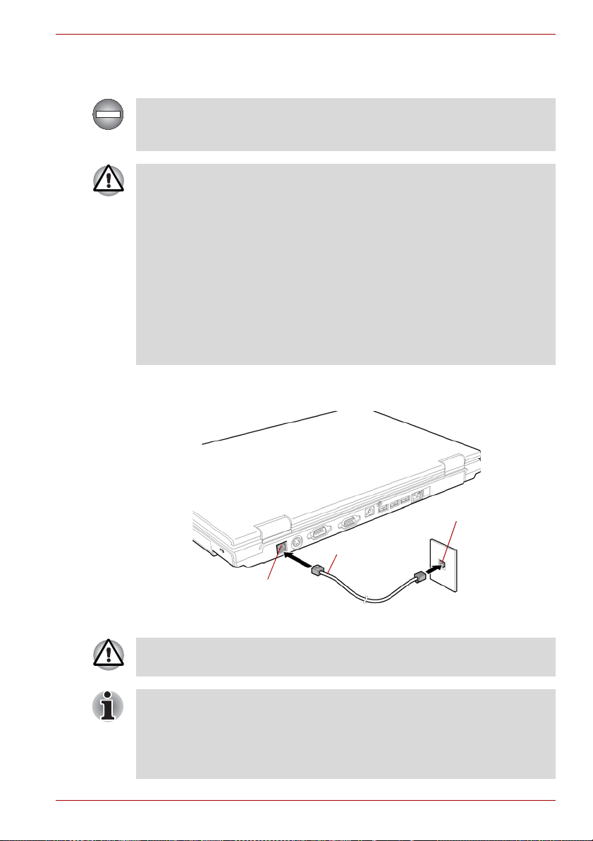
Connecting
To connect the modular cable, follow the steps below.
The modular cable that comes with the computer must be used to connect
the modem. Connect the end of the modular cable with the core to the
computer.
■ Connection to any communication line other than an analog phone line
could cause a PC system failure.
■ Connect the built-in modem only to ordinary analog phone lines.
■ Never connect the built-in modem to a digital line (ISDN).
■ Never connect the built-in modem to the digital connector on a
public telephone or to a digital private branch exchange (PBX).
■ Never connect the built-in modem to a key telephone system for
residences or offices.
■ Never operate your PC on AC power during a thunderstorm. If you see
lightning or hear thunder, immediately turn off the PC. An electric surge
caused by the storm, may result in a system failure, loss of data or
hardware damage.
1. Plug one end of the modular cable into the computer’s modem jack.
2. Plug the other end of the modular cable into a telephone jack.
Operating Basics
Telephone jack
Modular cable
Modem jack
Figure 4-10 Connecting the internal modem
Do not pull on the cable or move the computer while the cable is
connected.
If you use a storage device such as an optical drive or hard disk drive
connected to a 16-bit PC card, you might experience the following modem
problems:
■ Modem speed is slow or communication is interrupted.
■ Skips may occur in sound.
User’s Manual 4-21
Page 80

Operating Basics
Disconnecting
To disconnect the internal modular cable, follow the steps below.
1. Pinch the lever on the connector in the telephone jack and pull out the
connector.
2. Disconnect the cable from the computer’s modem jack in the same
manner.
Wireless communications
The computer’s wireless communication function supports both Wireless
LAN and Bluetooth devices.
All models are provided with Wireless Communication switch. Some
models are equipped with both Wireless LAN and Bluetooth functions.
Wireless LAN
The Wireless LAN is compatible with other LAN systems based on Direct
Sequence Spread Spectrum /Orthogonal Frequency Division Multiplexing
radio technology that complies with IEEE802.11 Wireless LAN standard
(Revision A, B or G).
■ Theoretical maximum speed: 54Mbps (IEEE802.11a, 802.11g)
■ Theoretical maximum speed: 11Mbps (IEEE802.11b)
■ Frequency Channel Selection
(Revision A: 5 GHz, Revision B/G: 2.4 GHz)
■ Roaming over multiple channels
■ Card Power Management
■ Wired Equivalent Privacy (WEP) data encryption, based on 128 bit
encryption algorithm. (Intel module type).
■ Wired Equivalent Privacy (WEP) data encryption, based on 152 bit
encryption algorithm. (Atheros module type).
■ Wi-Fi Protected Access (WPA).
■ Advanced Encryption Standard (AES) data encryption.
■ Wake-up on Wireless LAN (Intel module type)
Do not install or remove an optional memory module while Wake-up on
Wireless LAN is enabled.
4-22 User’s Manual
Page 81

■ The Wake-up on Wireless LAN function consumes power even when
the system is off. Leave the AC adaptor connected while using this
feature.
■ The values shown above are the theoretical maximums for Wireless
LAN standards. The actual values may differ.
■ The transmission speed over the Wireless LAN, and the distance over
which the Wireless LAN can reach, may vary depending on
surrounding electromagnetic environment, obstacles, access point
design and configuration, client design and software/hardware
configurations. The transmission rate described is the theoretical
maximum speed as specified under the appropriate standard - the
actual transmission speed will be lower than the theoretical maximum
speed.
■ The Wake-up on Wireless LAN function is effective only when it is
connected with AP. This function becomes invalid when the connection
is cut.
■ The Wake-up on Wireless LAN function is not available in battery
mode.
Security
■ TOSHIBA strongly recommend that you enable WEP (encryption)
functionality, otherwise your computer will be open to illegal access by
an outsider using a wireless connection. If this occurs, the outsider may
illegally access your system, eavesdrop, or cause the loss or
destruction of stored data.
■ TOSHIBA is not liable for the loss of data due to eavesdropping or
illegal access through the Wireless LAN and the damage thereof.
Operating Basics
Bluetooth wireless technology
Some models in this series are equipped with Bluetooth™ wireless
technology that eliminates the need for cables between electronic devices
such as desktop computers, printers and mobile phones.
You cannot use the built-in Bluetooth functions and an optional Bluetooth
SD card 3 simultaneously.
Bluetooth wireless technology has the following features:
Worldwide operation
The Bluetooth radio transmitter and receiver operate in the 2.4 GHz band,
which is license-free and compatible with radio systems in most countries
in the world.
Radio links
You can easily establish links between two or more devices. The link is
maintained even if the devices are not within line of sight.
User’s Manual 4-23
Page 82

Operating Basics
Security
Two advanced security mechanisms ensure a high level of security:
■ Authentication prevents access to critical data and makes it impossible
to falsify the origin of a message.
■ Encryption prevents eavesdropping and maintains link privacy.
Bluetooth™ Stack for Windows® by TOSHIBA
Please note that this software is specifically designed for the following
operating systems:
®
■ Microsoft
■ Microsoft
Detailed information regarding the use with these operating systems is
listed below. Please refer also to the electronic information which is
included with each software.
This Bluetooth™ Stack is based on Bluetooth™ Version 1.1/1.2/2.0+EDR
specification. TOSHIBA cannot confirm compatibility between any PC
products and/or other electronic devices that use Bluetooth™ other than
TOSHIBA mobile PCs.
Windows® 2000 Professional
®
Windows® XP
Release Notes related to the Bluetooth™ Stack for
®
Windows
1. Install:
On Windows2000 or Windows XP, Bluetooth™ Stack for Windows® by
TOSHIBA does not have a digital signature.
2. Fax application software:
Regarding FAX application software, there are some software that you
cannot use on this Bluetooth™ Stack.
3. Multi User:
On Windows XP, the use of Bluetooth is not supported in a multi-user
environment. This means that, when you use Bluetooth, other users
logged onto the same computer will not be able to use its Bluetooth
functionality.
by TOSHIBA
Product Support:
The latest information regarding Operating System support,
Language Support or available upgrades can be found on our web site
http://www.toshiba-europe.com/computers/tnt/bluetooth.htm in Europe or
www.pcsupport.toshiba.com in the United States.
4-24 User’s Manual
Page 83

Wireless communication switch
You can enable or disable Wireless LAN and Bluetooth functions, with the
on/off switch. No transmissions are sent or received when the switch is off.
Slide the switch to the right to turn it on and to the left to turn it off.
■ Do not use the Wireless LAN or Bluetooth functionalities near a
microwave oven or in areas subject to radio interference or magnetic
fields. Interference from a microwave oven or other source can disrupt
Wireless LAN or Bluetooth operation.
■ Turn Wireless LAN and Bluetooth functionalities off when near a
person who may have a cardiac pacemaker implant or other medical
electric device. Radio waves may affect pacemaker or medical device
operation, possibly resulting in serious injury. Follow the instruction of
your medical device when using any Wireless LAN or Bluetooth
functionality.
■ Always turn off Wireless LAN or Bluetooth functionality if the PC is near
automatic control equipment or appliances such as automatic doors or
fire detectors. Radio waves can cause malfunction of such equipment,
possibly resulting in serious injury.
Wireless communication Indicator
The wireless communication indicator indicates the status of the wireless
communication functions.
Indicator status Indication
Operating Basics
Indicator off Wireless communication switch is set to off.
Indicator glows Wireless communication switch is on. Wireless
If you used the Task Bar to disable the Wireless LAN, restart the computer
or perform the following procedure to re-enable it: start, Control Panel,
System, Hardware Device Manager, Network adapters, IntelR
PRO/Wireless 3945BG/3945ABG Network Connection or Atheros
AR5006EG/AR5006EX Wireless Network Adapter and enable.
User’s Manual 4-25
Automatic power down because of overheating.
Power malfunction.
LAN or Bluetooth is turned on by an application.
Page 84

Operating Basics
LAN
The computer has built-in support for Ethernet LAN (10 megabits per
second, 10BASE-T), Fast Ethernet LAN (100 megabits per second,
100BASE-TX) and Gigabit Ethernet LAN (1000 megabits per second,
1000BASE-T (only for Intel
This section describes how to connect/disconnect to a LAN.
Do not install or remove an optional memory module while Wake-up on
LAN is enabled.
■ The Wake-up on LAN function consumes power even when the system
■ The link speed (10/100/1000 megabits per second) switches
LAN cable types
The computer must be configured properly before connecting to a LAN.
Logging onto a LAN using the computer’s default settings could cause a
malfunction in LAN operation. Check with your LAN administrator
regarding set-up procedures.
If you are using Gigabit Ethernet LAN (1000 megabits per second,
1000BASE-T), be sure to connect with a CAT5E cable or higher. You
cannot use a CAT3 or CAT5 cable.
If you are using Fast Ethernet LAN (100 megabits per second,
100BASE-TX), be sure to connect with a CAT5 cable or higher. You cannot
use a CAT3 cable.
If you are using Ethernet LAN (10 megabits per second, 10BASE-T), you
can connect with a CAT3 or higher.
®
Core™ Duo/Solo Processor models)).
is off. Leave the AC adaptor connected while using this feature.
automatically according to your network environment (connected
devices, cables, noise etc.).
Connecting LAN cable
To connect the LAN cable, follow the steps below.
■ Connect the AC adaptor before connecting the LAN cable. The AC
adaptor must remain connected during LAN use. If you disconnect the
AC Adaptor while the computer is accessing a LAN, the system may
hang up.
■ Do not connect any other cable to the LAN jack except the LAN cable.
Otherwise, malfunctions or damage may occur.
■ Do not connect any power supplying device to the LAN cable that is
connected to the LAN jack. Otherwise, malfunctions or damage may
occur.
4-26 User’s Manual
Page 85

1. Turn off the power to the computer and to all external devices
connected to the computer.
2. Plug one end of the cable into the LAN jack. Press gently until you hear
the latch click into place.
LAN connector
LAN jack
Figure 4-11 Connecting the LAN cable
3. Plug the other end of the cable into a LAN hub connector. Check with
your LAN administrator before connecting to a hub.
When the computer is exchanging data with the LAN, the LAN Active
indicator glows orange. When the computer is connected to a LAN hub but
is not exchanging data, the Link indicator glows green.
Disconnecting LAN cable
To disconnect the LAN cable, follow the steps below.
Operating Basics
Make sure the LAN Active indicator (orange LED) is out before you
disconnect the computer from the LAN.
1. Pinch the lever on the connector in the computer’s LAN jack and pull
out the connector.
2. Disconnect the cable from the LAN hub in the same manner. Check
with your LAN administrator before disconnecting from the hub.
Cleaning the computer
To help ensure long, trouble-free operation, keep the computer free of dust
and use care with liquids around the computer.
■ Be careful not to spill liquids into the computer. If the computer does get
wet, turn the power off immediately and let the computer dry completely
before you turn it on again.
■ Clean the computer using a slightly damp (with water) cloth. You can
use glass cleaner on the LCD display screen. Spray a small amount of
cleaner on a soft, clean cloth and wipe the screen gently with the cloth.
Never spray cleaner directly onto the computer or let liquid run into any
part of it. Never use harsh or caustic chemical products to clean the
computer.
User’s Manual 4-27
Page 86

Operating Basics
Moving the computer
The computer is designed for rugged durability. However, a few simple
precautions taken when moving the computer will help ensure trouble-free
operation.
■ Before moving the computer, it recommends changing the function of
HDD Protection. Refer to the section, Using the Hard Disk Drive (HDD)
Protection, in this chapter.
■ Make sure all disk activity has ended before moving the computer.
Check the HDD indicator on the computer.
■ If a CD/DVD is in the drives, remove it. Also make sure the disc tray is
securely closed.
■ Turn off the power to the computer.
■ Disconnect the AC adaptor and all peripherals before moving the
computer.
■ Close the LCD display panel. Do not pick up the computer by its display
panel.
■ Before carrying your computer, shut down the computer, disconnect the
power cable and wait until the PC cools down. Failure to follow this
instruction could result in minor injury.
■ Always turn off the power when you move the computer. If the power
button has a lock, set it to the lock position. Also be careful not to
subject the computer to impact. Failure to follow this instruction could
result in damage to computer, computer failure or loss of data.
■ Never transport your computer with PC cards installed. This could
cause damage to your computer and/or PC card, resulting in product
failure.
■ Use the carrying case when transporting the computer.
■ When carrying your computer, be sure to hold it securely so that it does
not fall or hit anything.
■ Do not carry your computer by holding protruded portions.
Using the Hard Disk Drive (HDD) Protection
This computer has a function for reducing the risk of damage on hard disk
drive.
Using the acceleration sensor built in the computer, HDD Protection detects
vibration, shocks, and those signs in the computer, and automatically
moves the HDD (Hard Disk Drive) head to the safe position to reduce the
risk of damage that could be caused to the disk by head-to-disk contact.
■ This function does not guarantee that the hard disk drive will not be
damaged.
■ A secondary hard disk drive fitted to the computer is not supported by
the HDD protection function.
4-28 User’s Manual
Page 87

Operating Basics
When vibration is detected, the following message is displayed, and the
icon in the notification area of the taskbar is changed to the protection
state. This message is displayed until the OK button is pressed or
30 seconds pass. When vibration subsides, the icon returns to the normal
state.
Figure 4-12 HDD Protection Message
Taskbar Icon
State Icon Description
Normal HDD Protection is enabled.
Protection HDD Protection is active. The hard disk drive
head is in a safe position.
OFF HDD Protection is disabled.
TOSHIBA HDD Protection Properties
You can make the HDD Protection settings by using the TOSHIBA HDD
Protection Properties window. To open the window, click start, point to All
Programs, point to TOSHIBA, point to Utilities and click HDD Protection
setting. The window can also be started from the icon on the Taskbar, or
from the Control Panel.
Figure 4-13 TOSHIBA HDD Protection Properties
User’s Manual 4-29
Page 88

Operating Basics
Details
HDD Protection
You can choose whether to enable or disable HDD Protection.
Detection Level
This function can be set to four levels. The sensitivity levels in which
vibrations, impacts and their similar signs are detected can be set to OFF,
1, 2 and 3 in ascending order. Level 3 is recommended for better protection
of the computer. However, when the computer is used as handheld or in
other unstable conditions, setting the detection level to 3 could result in
frequent execution of HDD Protection, which will slow HDD reading and
writing. Set a lower detection level when the speed of HDD reading and
writing is a priority.
Different detection levels can be set depending on whether the computer is
used as handheld or mobile usages, or whether it is used in a stable
environment such as on a table in the workplace or at home. By setting
different detection levels for the computer depending on whether it runs
with the AC power (desktop) or with batteries (handheld or mobile usage),
the detection level automatically switches according to the power
connection mode.
To open the Details window, click the Setup Detail button in the TOSHIBA
HDD Protection Properties window.
Figure 4-14 Details
Detection Level Amplification
When the AC adaptor is disconnected or the lid is closed, HDD Detection
assumes that the computer will be carried and sets the detection level to
the maximum for 10 seconds.
HDD Protection Message
Specify whether to display a message when HDD Protection is active.
■ This function does not work when the computer is starting, in standby,
in hibernation, in transition to hibernation, recovering from hibernation,
or powered off. Be sure to not subject the computer to vibration or
impact while the function is disabled.
■ This function supports only Windows® XP.
4-30 User’s Manual
Page 89

Heat dispersal
To protect from overheating, the CPU has an internal temperature sensor. If
the computer’s internal temperature rises to a certain level, the cooling fan
is turned on or the processing speed is lowered. You can select whether to
control the CPU temperature by turning on the fan first, then if necessary,
lowering the CPU speed. Or, by lowering the CPU speed first, then if
necessary, turning on the fan. Use the Cooling Method item of the Basic
Setup tab in TOSHIBA Power Saver.
When the CPU temperature falls to a normal range, the fan is turned off
and the CPU operation returns to standard speed.
If the CPU temperature reaches an unacceptably high level with either
setting, the system automatically shuts down to prevent damage. Data in
memory will be lost.
Operating Basics
User’s Manual 4-31
Page 90

Operating Basics
4-32 User’s Manual
Page 91

The Keyboard
The computer’s keyboard layouts are compatible with a 101/102-key
enhanced keyboard. By pressing some keys in combination, all the
101/102-key keyboard functions can be executed on the computer.
The number of keys on your keyboard depends on which country/region’s
keyboard layout your computer is configured with. Keyboards for numerous
languages are available.
There are six types of keys: typewriter keys, function keys, soft keys, Hot
keys, Windows special keys and keypad overlay.
Typewriter keys
The typewriter keys produce the upper- and lower-case letters, numbers,
punctuation marks, and special symbols that appear on the screen.
There are some differences, however, between using a typewriter and
using a computer keyboard:
■ Letters and numbers produced in computer text vary in width. Spaces,
which are created by a “space character,” may also vary depending on
line justification and other factors.
■ The lowercase l (el) and the number 1 (one) are not interchangeable on
computers as they are on a typewriter.
■ The uppercase O (oh) and the 0 (zero) are not interchangeable.
■ The Caps Lock function key locks only the alphabetic characters in
uppercase while the shift lock on a typewriter places all keys in the
shifted position.
■ The Shift keys, the Tab key, and the BkSp (backspace) key perform the
same function as their typewriter counterparts but also have special
computer functions.
Chapter 5
User’s Manual 5-1
Page 92

The Keyboard
Function keys: F1 … F12
The function keys (not to be confused with Fn) are the 12 keys at the top of
your keyboard. These keys function differently from other keys.
F1 through F12 are called function keys because they execute
programmed functions when pressed. Used in combination with the Fn key,
keys marked with icons execute specific functions on the computer. Refer
to the section, Soft keys: Fn key combinations, in this chapter. The function
executed by individual keys depends on the software you are using.
Soft keys: Fn key combinations
The Fn (function) is unique to TOSHIBA computers and is used in
combination with other keys to form soft keys. Soft keys are key
combinations that enable, disable or configure specific features.
Some software may disable or interfere with soft-key operations. Soft-key
settings are not restored by the Standby feature.
Emulating keys on enhanced keyboard
Esc
F1
F3 F4 F5 F6 F7 F8 F9 F10 F11 F12
F2
(9 )
<
,
_
-
0
:
;
>
.
Alt
Tab
~
`
CapsLock
Ctrl
#
!
1
QW RTYU IO P
Shift
$4%
@
2
3
E
ASDFGHJ KL
CXZB
Alt
&
^
68
5
7
V
*
MN
{[}
?
/
Pause
PrtSc
Scroll
SysReq
Break
lock
+
Bk Sp
=
]
,,
,
Ins
Del
\
Enter
Shift
Ctrl
Num
PgUp
Home
End
PgDn
*
/
.
Lock
7
8 9
Home
PgUp
+
654
3
1
2
PgDn
End
0
Ins
Enter
.
Del
Figure 5-1 A 101-key enhanced keyboard layout
The keyboard is designed to provide all the features of the 101-key
enhanced keyboard, shown in figure 5-1. The 101/102-key enhanced
keyboard has a numeric keypad and scroll lock key. It also has additional
Enter and Ctrl keys to the right of the main keyboard. Since the keyboard
is smaller and has fewer keys, some of the enhanced keyboard functions
must be simulated using two keys instead of one on the larger keyboard.
Your software may require you to use keys that the keyboard does not
have. Pressing the Fn key and one of the following keys simulates the
enhanced keyboard’s functions.
5-2 User’s Manual
Page 93

The Keyboard
Press Fn + F10 or Fn + F11 to access the integrated keypad. When
activated, the keys with gray markings on the bottom edge become
numeric keypad keys (Fn + F11) or cursor control keys (Fn + F10). Refer to
the Keypad overlay section in this chapter for more information on how to
operate these keys. The power on default for both settings is off.
Press Fn + F12 (ScrLock) to lock the cursor on a specific line. The power
on default is off.
Press Fn + Enter to simulate Enter on the enhanced keyboard’s numeric
keypad.
Press Fn + Ctrl to simulate the enhanced keyboard’s right Ctrl key.
Hot keys
Hot keys (Fn + a function or Esc key) let you enable or disable certain
features of the computer.
Sound mute: Pressing Fn + Esc in a Windows environment turns sound
on or off. When you press these hot keys, the current setting will change
and be displayed as an icon.
User’s Manual 5-3
Page 94

The Keyboard
Instant security: Press Fn + F1 to blank the screen to prevent others from
accessing your data. To restore the screen and original settings, press any
key or press the Dual Pointing Device. If a screensaver password is
registered, a dialog box will appear. Enter the screensaver password and
click OK. If no password is set, the screen will be restored when you press
any key or press the Dual Pointing Device.
Power save mode: Pressing Fn + F2 changes the power save mode.
If you press Fn + F2 in a Windows environment, the settings dialog box for
the Power Save Mode will be displayed. Continue holding down Fn, and
release and press F2 again to toggle between the settings. Release both
Fn and F2 to put the new setting into effect. You can also change this
setting through the Profile options in TOSHIBA Power Saver.
Standby: When you press Fn + F3, the computer enters the Standby
Mode. Before entering Standby, a dialog box appears asking for your
confirmation. This dialog box will not be displayed in the future when you
click the check box.
Hibernation: When you press Fn + F4, the computer enters the
Hibernation Mode. Before entering Hibernation, a dialog box appears
asking for your confirmation. This dialog box will not be displayed in the
future when you click the check box.
5-4 User’s Manual
Page 95

The Keyboard
Display selection: Press Fn + F5 to change the active display device.
When you press these hot keys, a dialog box appears. Only selectable
devices will be displayed. Hold down Fn and press F5 again to change the
device. When you release Fn and F5, the selected device will change. If
you hold down these hot keys for five seconds the selection will return to
the internal LCD.
Internal LCD screen Brightness: Pressing Fn + F6 decreases the LCD
screen brightness in decrements. When you press these hot keys, the
current setting will be displayed for two seconds by an icon. You can also
change this setting through the Screen brightness item of the Basic Setup
tab in TOSHIBA Power Saver.
Internal LCD screen Brightness: Pressing Fn + F7 increases the LCD
screen brightness in increments. When you press these hot keys, the
current setting will be displayed for two seconds by a pop-up icon. You can
also change this setting through the Screen brightness item of the Basic
Setup tab in TOSHIBA Power Saver.
■ The brightness level is always set at the maximum value for about 18
seconds, when the internal LCD screen turns on.
■ LCD screen clarity increases with the brightness level.
Wireless setting: If your computer has both Bluetooth and Wireless LAN
functions, you can press Fn + F8 to select which type of wireless
communication you want to use. When you press these hot keys, a dialog
box will appear. Continue holding down Fn and press F8 to change the
setting. If wireless communication is turned off, Disabled Wireless
Communication Switch will be displayed.
If no wireless communication device is installed, no dialog box will appear.
User’s Manual 5-5
Page 96

The Keyboard
Dual Pointing Device: Pressing Fn + F9 in a windows environment
enables or disables the Dual Pointing Device function. When you press
these hot keys, the current setting will change and be displayed as an icon.
LCD screen resolution selection: Press Fn + Space keys to change the
display resolution. Each time when you press these hot keys, the LCD
screen resolution changes as follows: The available resolution depends
on the model. With XGA, you can change the resolution between
800 × 600 and 1024 × 768 pixels. With SXGA, between 800 × 600 and
1400 × 1050 pixels.
Optical disk drive power icon: Press the Fn + Tab keys to turn the power
of the optical disk drive on or eject the disc tray. A dialog box is displayed
when this hotkey is pressed. To choose between the functions, press the
Tab key while holding down the Fn key. The chosen function is executed
when the Fn + Tab keys are released.
TOSHIBA Zooming Utility (reduce): To reduce the icon size on the
desktop or the application window, press the 1 key while holding down the
Fn key.
TOSHIBA Zooming Utility (enlarge): To enlarge the icon size on the
desktop or the application window, press the 2 key while holding down the
Fn key.
Fn Sticky key
You can use the TOSHIBA Accessibility Utility to make the Fn key sticky,
that is, you can press it once, release it, and then press an “F number” key.
To start the TOSHIBA Accessibility Utility, click start, point to All
Programs, point to TOSHIBA, point to Utilities and click Accessibility.
5-6 User’s Manual
Page 97

Windows special keys
The keyboard provides two keys that have special functions in Windows:
Windows logo key activates the start menu and the other, the application
key, has the same function as the secondary mouse button.
This key activates the Windows start menu.
This key has the same function as the secondary mouse button.
Keypad overlay
Your computer’s keyboard does not have an independent numeric keypad,
but its numeric keypad overlay functions like one.
The keys in the center of the keyboard with gray letters make up the
numeric keypad overlay. The overlay provides the same functions as the
numeric keypad on the 101/102-key enhanced keyboard in figure 5-2.
Turning on the overlays
The numeric keypad overlay can be used for numeric data input or cursor
and page control.
The Keyboard
Arrow mode
To turn on the Arrow mode, press Fn + F10. The Arrow mode indicator
lights. Now try cursor and page control using the keys shown in figure 5-2.
Press Fn + F10 again to turn off the overlay.
User’s Manual 5-7
Page 98

The Keyboard
Numeric mode
To turn on the Numeric mode, press Fn + F11. The Numeric mode
indicator lights. Now try numeric data entry using the keys in figure 5-2.
Press Fn + F11 again to turn off the overlay.
Figure 5-2 The numeric keypad overlay
Temporarily using normal keyboard (overlay on)
While using the overlay, you can temporarily access the normal keyboard
without turning off the overlay:
1. Hold Fn and press any other key. All keys will operate as if the overlay
were off.
2. Type upper-case characters by holding Fn + Shift and pressing a
character key.
3. Release Fn to continue using the overlay.
Temporarily using overlay (overlay off)
While using the normal keyboard, you can temporarily use the keypad
overlay without turning it on:
1. Press and hold down Fn.
2. Check the keyboard indicators. Pressing Fn turns on the most recently
used overlay. If the Numeric mode indicator lights, you can use the
overlay for numeric entry. If the Arrow mode indicator lights, you can
use the overlay for cursor and page control.
3. Release Fn to return to normal keyboard operation.
5-8 User’s Manual
Page 99

Temporarily changing modes
If the computer is in Numeric mode, you can switch temporarily to Arrow
mode by pressing a shift key.
If the computer is in Arrow mode, you can switch temporarily to Numeric
mode by pressing a shift key.
Generating ASCII characters
Not all ASCII characters can be generated using normal keyboard
operation. But, you can generate these characters using their ASCII codes.
With the overlay on:
1. Hold down Alt.
2. Using the overlay keys, type the ASCII code.
3. Release Alt, and the ASCII character appears on the display screen.
With the overlay off:
1. Hold down Alt + Fn.
2. Using the overlay keys, type the ASCII code.
3. Release Alt + Fn, and the ASCII character appears on the display
screen.
The Keyboard
User’s Manual 5-9
Page 100

The Keyboard
5-10 User’s Manual
 Loading...