

Page 1
Satellite® A100/A105 Series Resource Guide
Keep this guide in a convenient place to access important
information about your computer.
If you need assistance, use one of the following:
❖ Toshiba’s Support Web site
pcsupport.toshiba.com
❖ Toshiba Global Support Centre
Calling within the United States (800) 457-7777
Calling from outside the United States (949) 859-4273
Please fill in for your reference and future use:
Model name______________________________________
Part number______________________________________
Serial number ____________________________________
Page 2

2
Contents
Introduction ...................................................................................... 25
Setting up your computer and getting started................................... 26
Your computer’s TFT display............................................................. 36
Inserting a PC Card........................................................................... 36
Learning the basics........................................................................... 37
Using the TouchPad™/Dual Mode Pad.............................................. 38
Using the Optical drive...................................................................... 39
Moving the computer........................................................................ 44
Mobile computing............................................................................. 44
Taking care of your battery ............................................................... 48
If something goes wrong.................................................................. 51
If you need further assistance........................................................... 56
Power cord/cable connectors ........................................................... 58
Features and specifications............................................................... 58
Legal Footnotes ................................................................................ 65
Index .................................................................................................68
Page 3

Handling the cord on this product will expose you to lead, a chemical known
to the State of California to cause birth defects or other reproductive harm.
Wash hands after handling.
Model: Satellite® A100/A105 Series
Recordable and/or ReWritable Drive(s) and
Associated Software Warranty
The computer system you purchased may include Recordable and/or
ReWritable optical media drive(s) and associated software, among the most
advanced data storage technologies available. As with any new technology,
you must read and follow all set-up and usage instructions in the applicable
user guides and/or manuals enclosed or provided electronically. If you fail
to do so, this product may not function properly and you may lose data or
suffer other damage. TOSHIBA AMERICA INFORMATION SYSTEMS,
INC. (“TOSHIBA”), ITS AFFILIATES AND SUPPLIERS DO NOT
WARRANT THAT OPERATION OF THE PRODUCT WILL BE
UNINTERRUPTED OR ERROR FREE. YOU AGREE THAT TOSHIBA,
ITS AFFILIATES AND SUPPLIERS SHALL HAVE NO
RESPONSIBILITY FOR DAMAGE TO OR LOSS OF ANY BUSINESS,
PROFITS, PROGRAMS, DATA, NETWORK SYSTEMS OR
REMOVABLE STORAGE MEDIA ARISING OUT OF OR RESULTING
FROM THE USE OF THE PRODUCT, EVEN IF ADVISED OF THE
POSSIBILITY THEREOF.
3
Protection of Stored Data
For your important data, please make periodic back-up copies of all the
data stored on the hard disk or other storage devices as a precaution against
possible failures, alteration, or loss of the data. IF YOUR DATA IS
ALTERED OR LOST DUE TO ANY TROUBLE, FAILURE OR
MALFUNCTION OF THE HARD DISK DRIVE OR OTHER
STORAGE DEVICES AND THE DATA CANNOT BE RECOVERED,
TOSHIBA SHALL NOT BE LIABLE FOR ANY DAMAGE OR LOSS
OF DATA, OR ANY OTHER DAMAGE RESULTING
THEREFROM. WHEN COPYING OR TRANSFERRING YOUR
DATA, PLEASE BE SURE TO CONFIRM WHETHER THE DATA
HAS BEEN SUCCESSFULLY COPIED OR TRANSFERRED.
TOSHIBA DISCLAIMS ANY LIABILITY FOR THE FAILURE TO
COPY OR TRANSFER THE DATA CORRECTLY.
Page 4

4
Critical Applications
The computer you have purchased is not designed for any “critical
applications.” “Critical applications” means life support systems, medical
applications, connections to implanted medical devices, commercial
transportation, nuclear facilities or systems or any other applications where
product failure could lead to injury to persons or loss of life or catastrophic
property damage. ACCORDINGLY, TOSHIBA, ITS AFFILIATES
AND SUPPLIERS DISCLAIM ANY AND ALL LIABILITY
ARISING OUT OF THE USE OF THE COMPUTER PRODUCTS IN
ANY CRITICAL APPLICATIONS. IF YOU USE THE COMPUTER
PRODUCTS IN A CRITICAL APPLICATION, YOU, AND NOT
TOSHIBA, ASSUME FULL RESPONSIBILITY FOR SUCH USE.
FCC Notice “Declaration of Conformity
Information”
This equipment has been tested and found to comply with the limits for a
Class B digital device, pursuant to Part 15 of the FCC rules. These limits
are designed to provide reasonable protection against harmful interference
in a residential installation.
This equipment generates, uses and can radiate radio frequency energy and,
if not installed and used in accordance with the instructions, it may cause
harmful interference to radio communications. However, there is no
guarantee that interference will not occur in a particular installation. If this
equipment does cause harmful interference to radio or television reception,
which can be determined by turning the equipment off and on, the user is
encouraged to try to correct the interference by one or more of the
following measures:
❖ Reorient or relocate the receiving antenna.
❖ Increase the separation between the equipment and receiver.
❖ Connect the equipment to an outlet on a circuit different from that to
which the receiver is connected.
❖ Consult the dealer or an experienced radio/TV technician for help.
Only Peripherals complying with the FCC Class B limits may be attached to
this equipment. Operation with noncompliant peripherals or peripherals not
recommended by Toshiba is likely to result in interference to radio and TV
reception. Shielded cables must be used between the external devices and
the computer's parallel port, monitor port, USB port, PS/2 port
port and microphone jack. Changes or modifications made to this equipment
not expressly approved by Toshiba or parties authorized by Toshiba could
void the user's authority to operate the equipment.
®
, i.LINK®
Page 5

This device complies with Part 15 of the FCC Rules. Operation is subject to
the following two conditions:
❖ This device may not cause harmful interference.
❖ This device must accept any interference received, including
interference that may cause undesired operation.
Contact either:
❖ Toshiba’s Support Web site at pcsupport.toshiba.com.
❖ Or call the Toshiba Global Support Centre:
Within the United States at (800) 457-7777
Outside the United States at (949) 859-4273
Industry Canada Requirement
This Class B digital apparatus complies with Canadian ICES-003.
Cet appareil numérique de la classe B est conformé à la norme NMB-003
du Canada.
FCC requirements
The following information is pursuant to FCC CFR 47, Part 68 and refers
to internal modems.
This equipment complies with Part 68 of the FCC rules. On the bottom of
this equipment is a label that contains, among other information, the FCC
registration number and ringer equivalence number (REN) for this
equipment. If requested, the information must be provided to the telephone
company.
The modem connects to the telephone line by means of a standard jack
called the USOC RJ11C.
A plug and jack used to connect this equipment to the premises wiring and
telephone network must comply with the applicable FCC part 68 rules and
requirements adopted by the ACTA. It is designed to be connected to a
compatible modular jack that is also compliant.
The REN is used to determine the number of devices that may be
connected to a telephone line. Excessive RENs on a telephone line may
result in the devices not ringing in response to an incoming call. In most but
not all areas, the sum of RENs should not exceed five (5.0). To be certain of
the number of devices that may be connected to a line, as determined by the
total RENs, contact the local telephone company. For products approved
after July 23, 2001, the REN for this product is part of the product identifier
that has the format US:AAAEQ##TXXXX. The digits represented by the
## are the REN without a decimal point (e.g., 03 is a REN of 0.3). For
earlier products, the REN is separately shown on the label.
5
Page 6

6
Connection to party line service is subject to state tariffs. Contact the state
public utility commission, public service commission or corporation
commission for information.
Telephone Company Procedures
The goal of the telephone company is to provide you with the best service it
can. In order to do this, it may occasionally be necessary for them to make
changes in their equipment, operations or procedures. If these changes
might affect your service or the operation of your equipment, the telephone
company will give you notice, in writing, to allow you to make any changes
necessary to maintain uninterrupted service.
If Problems Arise
If this equipment causes harm to the telephone network, the telephone
company will notify you in advance that temporary discontinuance of
service may be required. But if advanced notice is not practical, the
telephone company will notify the customer as soon as possible. Also, you
will be advised of your right to file a complaint with the FCC if you believe
it is necessary.
If trouble is experienced with this equipment, for repair or limited warranty
information, please contact Toshiba Corporation, Toshiba America
Information Systems, Inc. or an authorized representative of Toshiba, or the
Toshiba Support Centre within the United States at (800) 457-7777 or
Outside the United States at (949) 859-4273. If the equipment is causing
harm to the telephone network, the telephone company may request that
you disconnect the equipment until the problem is resolved.
Disconnection
If you should ever decide to permanently disconnect your modem from its
present line, please call the telephone company and let them know of this
change.
Fax Branding
The Telephone Consumer Protection Act of 1991 makes it unlawful for any
person to use a computer or other electronic device, including Fax
machines, to send any message unless such message clearly contains in a
margin at the top or bottom of each transmitted page or on the first page of
the transmission, the date and time it is sent and an identification of the
business or other entity, or other individual sending the message and the
telephone number of the sending machine or such business, other entity, or
individual. (The telephone number provided may not be a 900 number or
Page 7

any other number for which charges exceed local or long-distance
transmission charges.)
In order to program this information into your fax transmission, refer to the
fax software instructions installed on this computer.
Alarm Equipment
If your home has specially wired alarm equipment connected to the
telephone line, ensure the installation of this equipment does not disable
your alarm equipment. If you have questions about what will disable alarm
equipment, consult your telephone company or a qualified installer.
Instructions for IC CS-03 Certified Equipment
1 NOTICE: The Industry Canada label identifies certified equipment.
This certification means that the equipment meets certain
telecommunications network protective, operational and safety
requirements as prescribed in the appropriate Terminal Equipment
Technical Requirements document(s). The Department does not
guarantee the equipment will operate to the user’s satisfaction.
Before installing this equipment, users should ensure that it is
permissible to be connected to the facilities of the local
telecommunications company. The equipment must also be installed
using an acceptable method of connection. The customer should be
aware that compliance with the above conditions may not prevent
degradation of service in some situations.
Repairs to certified equipment should be coordinated by a
representative designated by the supplier. Any repairs or alterations
made by the user to this equipment, or equipment malfunctions, may
give the telecommunications company cause to request the user to
disconnect the equipment.
Users should ensure for their own protection that the electrical ground
connections of the power utility, telephone lines and internal metallic
water pipe system, if present, are connected together. This precaution
may be particularly important in rural areas.
Caution: Users should not attempt to make such connections
themselves, but should contact the appropriate electric inspection
authority, or electrician, as appropriate.
2 The user manual of analog equipment must contain the equipment’s
Ringer Equivalence Number (REN) and an explanation notice similar
to the following:
The Ringer Equivalence Number (REN) of this device can be found
on the label affixed to your computer.
NOTICE: The Ringer Equivalence Number (REN) assigned to each
terminal device provides an indication of the maximum number of
terminals allowed to be connected to a telephone interface. The
7
Page 8
8
termination on an interface may consist of any combination of devices
subject only to the requirement that the sum of the Ringer Equivalence
Numbers of all the devices does not exceed 5.
3 The standard connecting arrangement (telephone jack type) for this
equipment is jack type(s): USOC RJ11C.
Wireless Interoperability
The TOSHIBA Wireless LAN Mini PCI Card products are designed to be
interoperable with any wireless LAN product that is based on Direct
Sequence Spread Spectrum (DSSS) radio technology, and is compliant to:
❖ The IEEE 802.11 Standard on Wireless LANs (Revision A/B/G), as
defined and approved by the Institute of Electrical and Electronics
Engineers.
❖ The Wireless Fidelity (Wi-Fi) certification as defined by the Wi-Fi
Alliance. The “Wi-Fi CERTIFIED” logo is a certification mark of the
Wi-Fi Alliance.
Bluetooth® and Wireless LAN devices operate within the same radio
frequency range and may interfere with one another. If you use Bluetooth
and Wireless LAN devices simultaneously, you may occasionally
experience a less than optimal network performance or even lose your
network connection.
If you should experience any such problem, immediately turn off your Blue-
tooth or Wireless LAN device.
Please contact Toshiba PC product support on Web site http://www.toshibaeurope.com/computers/tnt/bluetooth.htm in Europe or pcsupport.toshiba.com in
the United States for more information.
Radio Frequency Interference Requirements
This device is restricted to indoor use due to its operation in the 5.15 GHz
to 5.25 GHz frequency range. FCC requires this product to be used indoors
for frequency range 5.15 GHz to 5.25 GHz to reduce the potential for harmful interference to co-channel Mobile Satellite systems.
High power radars are allocated as primary users of the 5.25 GHz to 5.35 GHz and
5.65 GHz to 5.85 GHz bands. These radar stations can cause interference with and/
or damage this device.
Wireless LAN and Your Health
Wireless LAN products, like other radio devices, emit radio frequency
electromagnetic energy. The level of energy emitted by Wireless LAN
devices however is far much less than the electromagnetic energy emitted
by wireless devices like for example mobile phones.
Because Wireless LAN products operate within the guidelines found in
radio frequency safety standards and recommendations, TOSHIBA
believes Wireless LAN is safe for use by consumers. These standards and
Page 9
recommendations reflect the consensus of the scientific community and
result from deliberations of panels and committees of scientists who
continually review and interpret the extensive research literature.
In some situations or environments, the use of Wireless LAN may be
restricted by the proprietor of the building or responsible representatives of
the organization. These situations may for example include:
❖ Using the Wireless LAN equipment on board airplanes, or
❖ In any other environment where the risk of interference to other
devices or services is perceived or identified as harmful.
If you are uncertain of the policy that applies on the use of wireless devices
in a specific organization or environment (e.g. airports), you are
encouraged to ask for authorization to use the Wireless LAN device prior to
turning on the equipment.
Exposure to Radio Frequency Radiation
The radiated output power of the TOSHIBA Wireless LAN Mini PCI Card is
far below the FCC radio frequency exposure limits. Nevertheless, the
TOSHIBA Wireless LAN Mini PCI Card shall be used in such a manner that
the potential for human contact during normal operation is minimized. In
normal operating configuration, the LCD in the upright position, the distance between the antenna and the user should not be less than 20 cm. The
antenna(s) used for this transmitter must not be co-located or operating in
conjunction with any other antenna or transmitter. Antenna(s) used in 5.15
GHz to 5.25 GHz frequency band must be integral antenna which provide
no access to the end user.
Refer to the Regulatory Statements as identified in the documentation that comes
with those products for additional information.
9
Regulatory Information
The TOSHIBA Wireless LAN Mini PCI Card must be installed and used in
strict accordance with the manufacturer’s instructions as described in the
user documentation that comes with the product. This device complies with
the following radio frequency and safety standards.
Canada – Industry Canada (IC)
This device complies with RSS 210 of Industry Canada.
The installer of this radio equipment must ensure that the antenna is located
or pointed such that it does not emit RF field in excess of Health Canada
limits for the general population; consult Safety Code 6, obtainable from
Health Canada’s Web site www.hc-sc.gc.ca/rpb. The RF device shall not be
co-located with any other transmitter that has not been tested with this
device.
Page 10
10
Operation is subject to the following two conditions: (1) this device may
not cause interference, and (2) this device must accept any interference,
including interference that may cause undesired operation of this device.
L’utilisation de ce dispositif est autorisée seulement aux conditions
suivantes: (1) il ne doit pas produire de brouillage et (2) l’utilisateur du
dispositif doit étre prêt à accepter tout brouillage radioélectrique reçu,
même si ce brouillage est susceptible de compromettre le fonctionnement
du dispositif.
The term “IC” before the equipment certification number only signifies that
the Industry Canada technical specifications were met.
To prevent radio interference to the licensed service, this device is intended
to be operated indoors and away from windows to provide maximum
shielding. Equipment (or its transmit antenna) that is installed outdoors is
subject to licensing.
Pour empecher que cet appareil cause du brouillage au service faisant
l'objet d'une licence, il doit etre utilize a l'interieur et devrait etre place loin
des fenetres afin de Fournier un ecram de blindage maximal. Si le matriel
(ou son antenne d'emission) est installe a l'exterieur, il doit faire l'objet
d'une licence.
This device is restricted to indoor use due to its operation in the 5.15 GHz
to 5.25 GHz frequency range. Industry Canada requires this product to be
used indoors for frequency range 5.15 GHz to 5.25 GHz to reduce the
potential for harmful interference to co-channel Mobile Satellite systems.
High power radars are allocated as primary users of the 5.25 GHz to 5.35 GHz and
5.65 GHz to 5.85 GHz bands. These radar stations can cause interference with
and/or damage this device.
EU Declaration of Conformity
TOSHIBA declares, that the product: PLU10* conforms to the following
Standards:
Supplementary
Information:
This product is carrying the CE-Mark in accordance with the related
European Directives. Responsible for CE-Marking is TOSHIBA Europe,
Hammfelddamm 8, 41460 Neuss, Germany.
*The product complies with the
requirements of the Low Voltage Directive
72/23/EEC, the EMC Directive 89/336/
EEC and/or the R&TTE Directive 1999/
05/EEC.
Page 11
VCCI Class B Information
Modem Warning Notice
Conformity Statement
The equipment has been approved to [Commission Decision “CTR-21”]
for pan-European single terminal connection to the Public Switched
Telephone Network (PSTN).
However, due to differences between the individual PSTNs provided in
different countries/regions the approval does not, of itself, give an
unconditional assurance of successful operation on every PSTN network
termination point.
In the event of problems, you should contact your equipment supplier in the
first instance.
The above Caution information applies to products that operate with an
802.11a device.
11
Taiwan
Article 14 Unless approved, for any model accredited low power radio frequency electric
machinery, any company, trader or user shall not change the frequency,
increase the power or change the features and functions of the original design.
Article 17 Any use of low power radio frequency electric machinery shall not affect
aviation safety and interfere with legal communications. In the event
interference is caused, the use of such electric machinery shall be immediately
discontinued. Operation of such products can be resumed only when they are
modified and can no longer cause interference.
The legal communications mentioned in the above item refer to radio
communications operated in accordance with telecommunication laws and
regulations.
Low power radio frequency electric machinery shall resist against
interference from legal communications or from industrial, scientific and
medical radio emission electric machinery.
Page 12
12
Using this Equipment in Japan
In Japan, the frequency bandwidth of 2,400 MHz to 2,483.5 MHz for
second generation low-power data communication systems such as this
equipment overlaps that of mobile object identification systems (premises
radio station and specified low-power radio station).
1. Sticker
Please put the following sticker on devices incorporating this product.
The frequency bandwidth of this equipment may operate within the
same range as industrial devices, scientific devices, medical
devices, microwave ovens, licensed radio stations and non-licensed
specified low-power radio stations for mobile object identification
systems (RFID) used in factory product lines (Other Radio Stations).
1. Before using this equipment, ensure that it does not interfere with
any of the equipment listed above.
2. If this equipment causes RF interference to other radio stations,
promptly change the frequency being used, change the location
of use, or turn off the source of emissions.
3. Contact TOSHIBA Direct PC if you have problems with interference
caused by this product to Other Radio Stations.
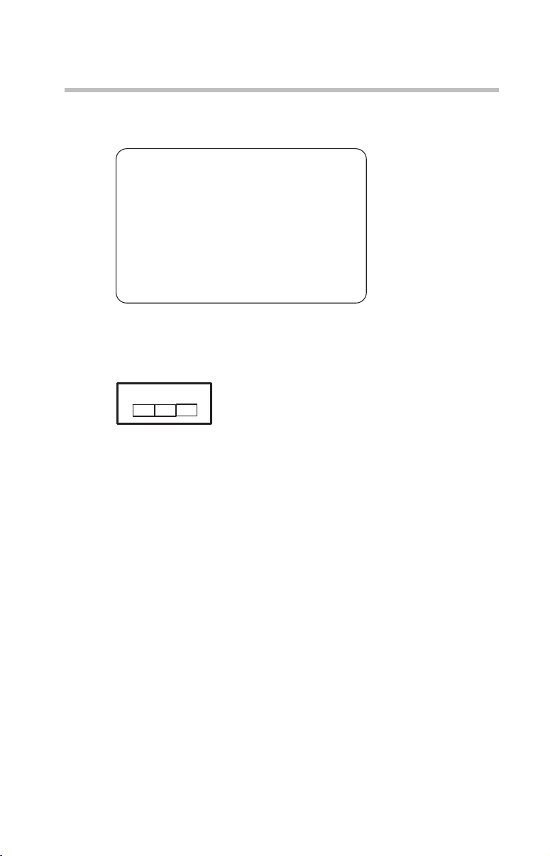
2. Indication
The indication shown below appears on this equipment.
(3)
(1) (2)
2.4DSOF4
(4)
1 2.4: This equipment uses a frequency of 2.4 GHz.
2 DS: This equipment uses DS-SS modulation.
OF: This equipment uses OFDM modulation.
3 The interference range of this equipment is less than 40m.
4 This equipment uses a frequency bandwidth from
2,400 MHz to 2,483.5 MHz.
It is possible to avoid the band of mobile object identification systems.
3. TOSHIBA Direct PC
Monday – Friday: 10:00 – 17:00
Toll Free Tel: 0120-13-1100
Direct Dial: 03-3457-5916
Fax: 03-5444-9450
Page 13
Device Authorization
This device obtains the Technical Regulation Conformity Certification and
the Technical Conditions Compliance Approval, and it belongs to the
device class of radio equipment of low-power data communication system
radio station stipulated in the Radio Law and the Telecommunications
Business Law of Japan.
The Name of the radio equipment: refer to the equipment label provided on
the computer
JAPAN APPROVALS INSTITUTE FOR TELECOMMUNICATIONS
EQUIPMENT
Approval Number: D01-1128JP
TELECOM ENGINEERING CENTER Approval Number: 03NY.A0018,
03GZDA0017
The following restrictions apply:
❖ Do not disassemble or modify the device.
❖ Do not install the embedded wireless module into other device.
❖ 5.17 GHz to 5.23 GHz for indoor use only.
Radio Approvals for Wireless Devices
13
The following information is dependent on what type of wireless device is in
your computer.
Approved Countries/Regions for use for the Atheros
AR5BMB-43/44 and AR5BMB5 Mini PCI Wireless
Network Adapters
This equipment is approved to the radio standard by the countries/regions
in the following table.
Do not use this equipment except in the countries/regions in the following table.
This device works on passive scan only.
A peer-to-peer mode is not available in 802.11a and Turbo Mode.
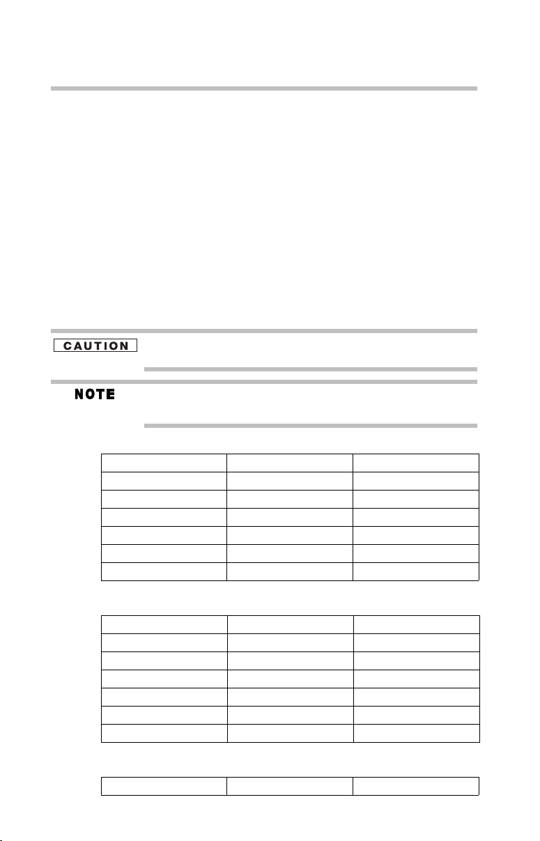
802.11b (2.4 GHz)
Australia Austria Belgium
Canada Denmark Finland
France Germany Greece
Page 14
14
Ireland Italy Liechtenstein
Luxembourg Netherlands New Zealand
Norway Portugal Sweden
Switzerland UK USA
Europe - Restrictions for use of 2.4 GHz Frequencies in
European Community Countries
België/
Belgique:
Deutschland: License required for outdoor installations. Check with reseller for
France: Restricted frequency band: only channels 1 to 7 (2400 MHz and 2454
Italia: License required for indoor use. Use with outdoor installations not
Nederland: License required for outdoor installations. Check with reseller for
For private usage outside buildings across public grounds over less than
300m no special registration with IBPT/BIPT is required. Registration to
IBPT/BIPT is required for private usage outside buildings across public
grounds over more than 300m. For registration and license please
contact IBPT/BIPT.
Voor privé-gebruik buiten gebouw over publieke groud over afstand
kleiner dan 300m geen registratie bij BIPT/IBPT nodig; voor gebruik
over afstand groter dan 300m is wel registratie bij BIPT/IBPT nodig.
Voor registratie of licentie kunt u contact opnemen met BIPT.
Dans le cas d’une utilisation privée, à l’extérieur d’un bâtiment, audessus d’un espace public, aucun enregistrement n’est nécessaire pour
une distance de moins de 300m. Pour une distance supérieure à 300m un
enregistrement auprès de I’IBPT est requise. Pour les enregistrements et
licences, veuillez contacter I’IBPT.
procedure to follow.
Anmeldung im Outdoor-Bereich notwendig, aber nicht
genehmigungspflichtig.Bitte mit Händler die Vorgehensweise
abstimmen.
MHz respectively) may be used outdoors in France. Please contact
A.R.T. (http://www.art-telecom.fr) for applicable procedures to follow.
Bande de fréquence restreinte: seuls les canaux 1- 7 (2400 et 2454 MHz
respectivement) doivent être utilisés endroits extérieur en France. Vous
pouvez contacter I’Autorité de Régulation des Télécommuniations
(http://www.art-telecom.fr) pour la procédure à suivre.
allowed.
E’necessaria la concessione ministeriale anche per l’uso interno.
Verificare con i rivenditori la procedura da seguire.
procedure to follow.
Licentie verplicht voor gebruik met buitenantennes. Neem contact op
met verkoper voor juiste procedure.
Page 15
802.11a (5 GHz)
Australia Austria Belgium
Canada Denmark Finland
France Germany Greece
Ireland Italy Liechtenstein
Luxembourg Netherlands New Zealand
Norway Portugal Sweden
Switzerland UK USA
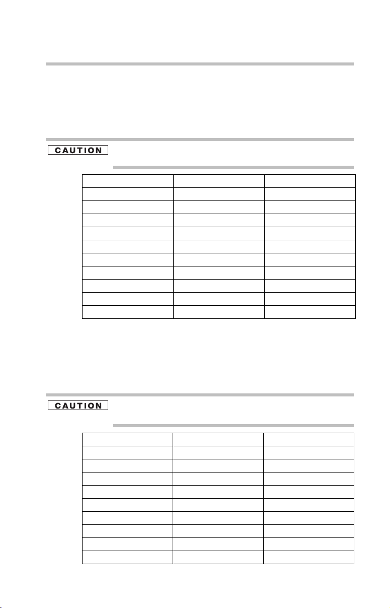
Turbo Mode (5 GHz)
Canada USA
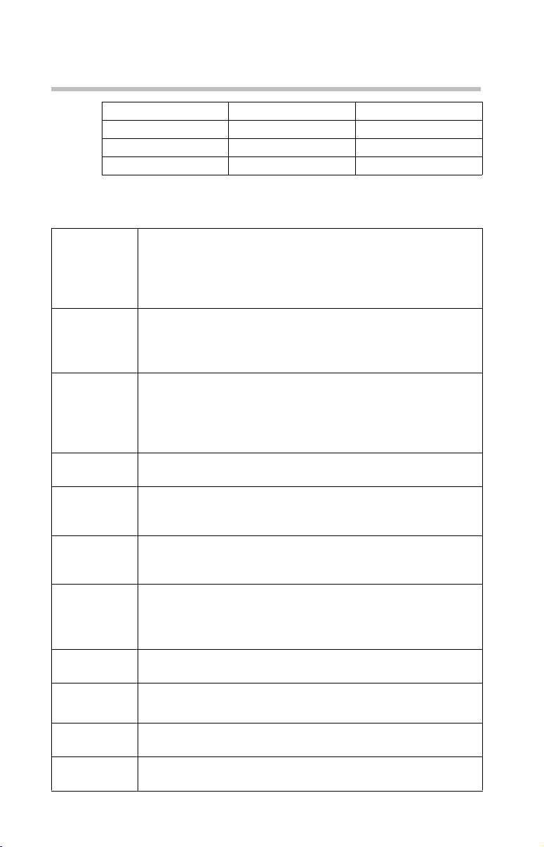
Europe - Restrictions for Use of 5 GHz Frequencies in
European Community Countries
European Community
Countries
Austria O x x
Belgium, France,
Switzerland/Lichtenstein
Denmark, Finland,
Germany, Greece,
Ireland, Italy,
Luxembourg,
Netherlands, Norway,
Portugal, Sweden, UK
Iceland, Spain O O O
5150-5250 MHz
Channels: 36, 40, 44,
48
Indoor Only
OO x
OO O
5250-5350 MHz
Channels: 52, 56, 60,
64
Indoor Only
5470-5725 MHz
Channels: 100, 104, 108, 112,
116, 120, 124, 128, 132, 136, 140
Indoor/Outdoor
15
O: allowed ×: forbidden
❖ To remain in conformance with European spectrum usage laws for Wireless
LAN operation, the above 2.4 GHz and 5 GHz channel limitations apply.
The user should use the wireless LAN utility to check the current channel of
operation. If operation is occurring outside of the allowable frequencies as
listed above, the user must cease operating the Wireless LAN at that
location and consult the local technical support staff responsible for the
wireless network.
❖ The 5 GHz Turbo mode feature is not allowed for operation in any
European Community country.
❖ This device must not be operated in ad-hoc mode using channels in the
5 GHz bands in the European Community. Ad-hoc mode provides a direct
communication between two client devices without a Wireless LAN Access
Point.
Page 16
16
❖ This device must be used with Access Points that have employed and
activated a radar detection feature required for European Community
operation in the 5 GHz bands. This device will operate under the control of
the Access Point in order to avoid operating on a channel occupied by any
radar system in the area. The presence of nearby radar operation may result
in temporary interruption of operation of this device. The Access Point’s
radar detection feature will automatically restart operation on a channel free
of radar. You may consult with the local technical support staff responsible
for the wireless network to ensure the Access Point device(s) are properly
configured for European Community operation.
Approved Countries/Regions for use for the Atheros
AR5001X Mini PCI Wireless Network Adapter
This equipment is approved to the radio standard by the countries/regions
in the following table.
Do not use this equipment except in the countries/regions in the following
table.
This device works on passive scan only.
A peer-to-peer mode is not available in 802.11a and Turbo Mode.
802.11b (2.4 GHz)
Australia Austria Belgium
Canada Denmark Finland
France Germany Greece
Ireland Italy Liechtenstein
Luxembourg Netherlands New Zealand
Norway Portugal Sweden
Switzerland UK USA
802.11a (5 GHz)
Australia Austria Belgium
Canada Denmark Finland
France Germany Greece
Ireland Italy Liechtenstein
Luxembourg Netherlands New Zealand
Norway Portugal Sweden
Switzerland UK USA
Turbo Mode (5 GHz)
Canada USA
Page 17
Approved Countries/Regions for use for the Intel®
PRO/Wireless LAN 2100 3B Mini PCI Adapter
This equipment is approved to the radio standard by the countries/regions
in the following table.
Do not use this equipment except in the countries/regions in the following
table.
Argentina Australia Austria
Belgium Brazil Canada
Chile Denmark Finland
France Germany Greece
Iceland Ireland Italy
Japan Liechtenstein Luxembourg
Mexico Netherlands New Zealand
Norway Peru Portugal
Singapore Spain Sweden
Switzerland UK Uruguay
USA Venezuela
17
Approved Countries/Regions for use for the Toshiba
Mini PCI Wireless LAN Card
This equipment is approved to the radio standard by the countries/regions
in the following table.
Do not use this equipment except in the countries/regions in the following
table.
Australia Austria Belgium
Canada Denmark Finland
France Germany Greece
Hong Kong Iceland Ireland
Italy Japan Liechtenstein
Luxembourg Malaysia Netherlands
New Zealand Norway Philippines
Portugal Singapore Spain
Sweden Switzerland Thailand
UK USA
Page 18
18
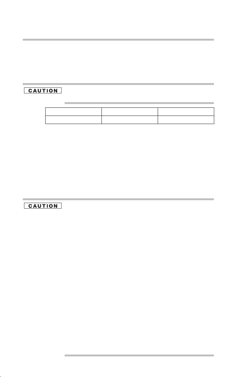
Approved Countries/Regions for use for the
INPROCOMM IPN2220 Wireless Network Adapter
This equipment is approved to the radio standard by the countries/regions
in the following table.
Do not use this equipment except in the countries/regions in the following
table.
EU Canada Japan
USA Australia New Zealand
Bluetooth® Wireless Technology
Interoperability
Bluetooth® Cards from TOSHIBA are designed to be interoperable with
any product with Bluetooth wireless technology that is based on Frequency
Hopping Spread Spectrum (FHSS) radio technology, and is compliant to:
❖ Bluetooth Specification as defined and approved by The Bluetooth
Special Interest Group.
❖ Logo certification with Bluetooth wireless technology as defined by
The Bluetooth Special Interest Group.
Bluetooth wireless technology is a new innovative technology, and
TOSHIBA has not confirmed compatibility of its Bluetooth products with all
PCs and/or equipment using Bluetooth wireless technology other than
TOSHIBA portable computers.
Always use Bluetooth cards from TOSHIBA in order to enable wireless networks over two or more (up to a total of seven) TOSHIBA portable computers using these cards. Please contact TOSHIBA PC product support on Web
site http://www.toshiba-europe.com/computers/tnt/bluetooth.htm in
Europe or pcsupport.toshiba.com in the United States for more information.
When you use Bluetooth cards from TOSHIBA close to 2.4 GHz Wireless
LAN devices, Bluetooth transmissions might slow down or cause errors. If
you detect certain interference while you use Bluetooth cards from
TOSHIBA, always change the frequency, move your PC to the area outside
of the interference range of 2.4 GHz Wireless LAN devices (40 meters/
43.74 yards or more) or stop transmitting from your PC. Please contact
TOSHIBA PC product support on Web site http://www.toshiba-europe.com/
computers/tnt/bluetooth.htm in Europe or pcsupport.toshiba.com in the
United States for more information.
Bluetooth and Wireless LAN devices operate within the same radio frequency
range and may interfere with one another. If you use Bluetooth and Wireless LAN
devices simultaneously, you may occasionally experience a less than optimal
network performance or even lose your network connection. If you should
experience any such problem, immediately turn off either one of your Bluetooth or
Wireless LAN. Please contact Toshiba PC product support on Web site http://
www.toshiba-europe.com/computers/tnt/bluetooth.htm in Europe or
pcsupport.toshiba.com in the United States for more information.
Page 19
Bluetooth® Wireless Technology and Your Health
The products with Bluetooth® wireless technology, like other radio devices,
emit radio frequency electromagnetic energy. The level of energy emitted
by devices with Bluetooth wireless technology however is far much less
than the electromagnetic energy emitted by wireless devices like for
example mobile phones.
Because products with Bluetooth wireless technology operate within the
guidelines found in radio frequency safety standards and recommendations,
TOSHIBA believes Bluetooth wireless technology is safe for use by
consumers. These standards and recommendations reflect the consensus of
the scientific community and result from deliberations of panels and
committees of scientists who continually review and interpret the extensive
research literature.
In some situations or environments, the use of Bluetooth wireless
technology may be restricted by the proprietor of the building or
responsible representatives of the organization. These situations may for
example include:
❖ Using the equipment with Bluetooth wireless technology on board
airplanes, or
❖ In any other environment where the risk of interference to other
devices or services is perceived or identified as harmful.
If you are uncertain of the policy that applies on the use of wireless devices
in a specific organization or environment (e.g. airports), you are
encouraged to ask for authorization to use the device with Bluetooth
wireless technology prior to turning on the equipment.
19
Exposure to Radio Frequency Radiation
The radiated output power of the Bluetooth Card from TOSHIBA is far below
the FCC radio frequency exposure limits. Nevertheless, the Bluetooth Card
from TOSHIBA shall be used in such a manner that the potential for human
contact during normal operation is minimized.
In order to comply with FCC radio-frequency radiation exposure guidelines
for an uncontrolled environment, the Bluetooth Card from TOSHIBA has to
be operated while maintaining a minimum body to antenna distance of 20
cm.
Refer to the Regulatory Statements as identified in the documentation that
comes with those products for additional information.
The Bluetooth Card from TOSHIBA is far below the FCC radio frequency
exposure limits.
Nevertheless, it is advised to use the Bluetooth Card from TOSHIBA in such a
manner that human contact during normal operation is minimized.
Page 20

20
Regulatory statements
This product complies with any mandatory product specification in any
country/region where the product is sold. In addition, the product complies
with the following:
European Union (EU) and EFTA
This equipment complies with the R&TTE directive 1999/5/EC and has
been provided with the CE mark accordingly.
Canada — Industry Canada (IC)
This device complies with RSS 210 of Industry Canada.
Taiwan
Article 14 Unless approved, for any model accredited low power radio frequency
electric machinery, any company, trader or user shall not change the
frequency, increase the power or change the features and functions of the
original design.
Article 17 Any use of low power radio frequency electric machinery shall not affect
aviation safety and interfere with legal communications. In the event
interference is caused, the use of such electric machinery shall be
immediately discontinued. Operation of such products can be resumed
only when they are modified and can no longer cause interference.
The legal communications mentioned in the above item refer to radio
communications operated in accordance with telecommunication laws and
regulations.
Low power radio frequency electric machinery shall resist against
interference from legal communications or from industrial, scientific and
medical radio emission electric machinery.
Using this Equipment in Japan
In Japan, the frequency bandwidth of 2,400 MHz to 2,483.5 MHz for
second generation low-power data communication systems such as this
equipment overlaps that of mobile object identification systems (premises
radio station and specified low-power radio station).
Page 21
1. Sticker
Please put the following sticker on devices incorporating this product.
The frequency bandwidth of this equipment may operate within the
same range as industrial devices, scientific devices, medical
devices, microwave ovens, licensed radio stations and non-licensed
specified low-power radio stations for mobile object identification
systems (RFID) used in factory product lines (Other Radio Stations).
1. Before using this equipment, ensure that it does not interfere with
any of the equipment listed above.
2. If this equipment causes RF interference to other radio stations,
promptly change the frequency being used, change the location
of use, or turn off the source of emissions.
3. Contact TOSHIBA Direct PC if you have problems with interference
caused by this product to Other Radio Stations.
2. Indication
The indication shown below appears on this equipment.
21
(1) (2)
(3)
2.4FH1
(4)
1 2.4: This equipment uses a frequency of 2.4 GHz.
2 FH: This equipment uses FH-SS modulation.
3 The interference range of this equipment is less than 10m.
4 This equipment uses a frequency bandwidth from 2,400 MHz to
2,483.5 MHz. It is impossible to avoid the band of mobile object
identification systems.
3. TOSHIBA Direct PC
Monday – Friday: 10:00 – 17:00
Toll Free Tel: 0120-13-1100
Direct Dial: 03-3457-5916
Fax: 03-5444-9450
Device Authorization
This device obtains the Technical Regulation Conformity Certification, and
it belongs to the device class of radio equipment of low-power data
communication system radio station stipulated in the Radio Law of Japan.
The Name of the radio equipment: EYXF2CS
TELECOM ENGINEERING CENTER
Approval Number: 01NYDA1305
Page 22
22
The following restrictions apply:
❖ Do not disassemble or modify the device.
❖ Do not install the embedded wireless module into other device.
Optical Drive Safety Instructions
The DVD-ROM and multi-function drives employ a laser system. To ensure
proper use of this product, please read this instruction manual carefully and
retain for future reference.
Never attempt to disassemble, adjust or repair a CD/DVD drive, CD-RW drive,
Multi-drive or any other optical drive. You could damage the drive. You would also
be exposed to laser light or other safety hazards, resulting in serious injury. Always
contact an authorized Toshiba service provider, if any repair or adjustment is
required.
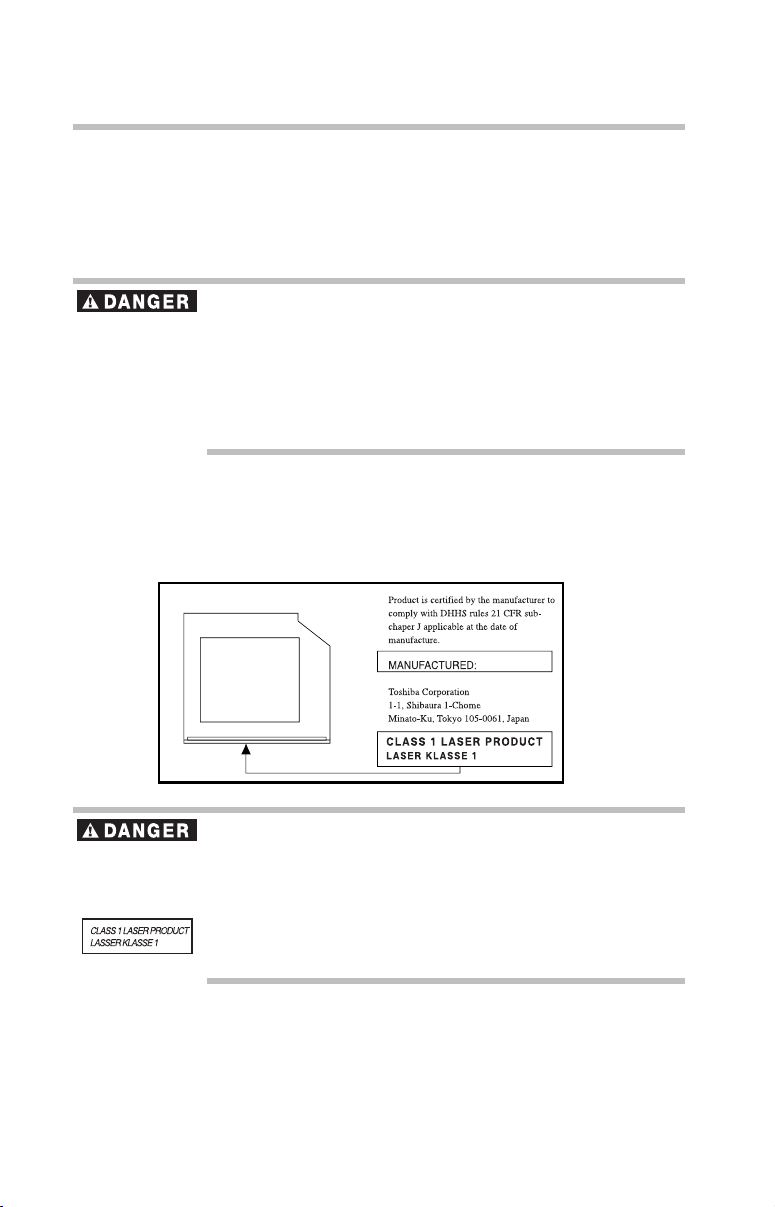
Location of the Required Label
(Sample shown below. Location of the label and manufacturing
information may vary.)
This appliance contains a laser system and is classified as a CLASS 1 LASER
PRODUCT. To use this model properly, read the user’s guide carefully and keep it
for your future reference.
Never attempt to disassemble, adjust or repair a CD/DVD drive, CD-RW drive,
Multi-drive or any other optical drive. You could damage the drive. You would also
be exposed to laser light or other safety hazards, resulting in serious injury. Always
contact an authorized Toshiba service provider, if any repair or adjustment is
required.
Page 23

Copyright
This guide is copyrighted by Toshiba America Information Systems, Inc.
with all rights reserved. Under the copyright laws, this guide cannot be
reproduced in any form without the prior written permission of Toshiba. No
patent liability is assumed, however, with respect to the use of the
information contained herein.
©2006 by Toshiba America Information Systems, Inc. All rights reserved.
Export Administration Regulation
This document contains technical data that may be controlled under the
U.S. Export Administration Regulations, and may be subject to the
approval of the U.S. Department of Commerce prior to export. Any export,
directly or indirectly, in contravention of the U.S. Export Administration
Regulations is prohibited.
Notice
The information contained in this manual, including but not limited to any
product specifications, is subject to change without notice.
TOSHIBA CORPORATION AND TOSHIBA AMERICA
INFORMATION SYSTEMS, INC. (TOSHIBA) PROVIDES NO
WARRANTY WITH REGARD TO THIS MANUAL OR ANY OTHER
INFORMATION CONTAINED HEREIN AND HEREBY EXPRESSLY
DISCLAIMS ANY IMPLIED WARRANTIES OF MERCHANTABILITY
OR FITNESS FOR ANY PARTICULAR PURPOSE WITH REGARD TO
ANY OF THE FOREGOING. TOSHIBA ASSUMES NO LIABILITY
FOR ANY DAMAGES INCURRED DIRECTLY OR INDIRECTLY
FROM ANY TECHNICAL OR TYPOGRAPHICAL ERRORS OR
OMISSIONS CONTAINED HEREIN OR FOR DISCREPANCIES
BETWEEN THE PRODUCT AND THE MANUAL. IN NO EVENT
SHALL TOSHIBA BE LIABLE FOR ANY INCIDENTAL,
CONSEQUENTIAL, SPECIAL, OR EXEMPLARY DAMAGES,
WHETHER BASED ON TORT, CONTRACT OR OTHERWISE,
ARISING OUT OF OR IN CONNECTION WITH THIS MANUAL OR
ANY OTHER INFORMATION CONTAINED HEREIN OR THE USE
THEREOF.
23
Page 24

24
Trademarks
Satellite is a registered trademark of Toshiba America Information
Systems, Inc. and/or Toshiba Corporation.
Microsoft and Windows are registered trademarks of Microsoft
Corporation in the United States and/or other countries.
Direct3D, DirectSound, and DirectMusic are registered trademarks of
Microsoft Corporation.
Wi-Fi is a registered trademark of the Wi-Fi Alliance.
Sound Blaster is a registered trademark of Creative Labs, Inc.
Dolby and the double-D symbol are trademarks of Dolby Laboratories.
Home Theater is a trademark of Dolby Laboratories.
Intel, Intel Core, Celeron, Centrino and Pentium are trademarks or
registered trademarks of Intel Corporation or its subsidiaries in the United
States and other countries.
TouchPad is a trademark of Synaptics, Inc.
Bluetooth word mark and logos are owned by the Bluetooth SIG, Inc. and
any use of such marks by Toshiba is under license. Other trademarks and
trade names are those of their respective owners.
All other brand and product names are trademarks or registered trademarks
of their respective companies.
Computer Disposal Information
This product contains mercury. Disposal of this material may be regulated
due to environmental considerations. For disposal, reuse or recycling
information, please contact your local government or the Electronic
Industries Alliance at www.eiae.org.
Page 25

Introduction
Welcome to the world of powerful and portable multimedia
computers!
Some software may differ from its retail version (if available),
and may not include user manuals or all program functionality.
This guide
This guide offers important information about your computer,
including solutions to the most common problems, and
features and specifications.
For more detailed information, descriptions of other features,
and more extensive troubleshooting guidelines, see the
electronic user’s guide preinstalled on your system. It is also
available on the Web at pcsupport.toshiba.com.
Safety icons
This guide contains safety instructions that must be observed
in order to avoid potential hazards that could result in
personal injuries, damage to your equipment, or loss of data.
These safety cautions have been classified according to the
seriousness of the risk, and icons highlight these instructions
as follows:
Introduction
25
Indicates an imminently hazardous situation which, if not avoided,
will result in death or serious injury.
Indicates a potentially hazardous situation which, if not avoided,
could result in death or serious injury.
Indicates a potentially hazardous situation which, if not avoided, may
result in minor or moderate injury.
Indicates a potentially hazardous situation which, if not avoided, may
result in property damage.
Provides important information.
Page 26

26
Setting up your computer and getting started
Other icons used
Additional icons highlight other helpful or educational
information:
TECHNICAL NOTE: This icon highlights technical information about
the computer.
HINT: This icon denotes helpful hints and tips.
DEFINITION: This icon indicates the definition of a term used in the
text.
Other documentation
Your computer comes with the following documentation in
addition to this resource guide:
❖ An electronic version of the user’s guide.
❖ It may also contain guides for other programs that may
come with your system.
For accessory information, visit Toshiba’s Web site at
accessories.toshiba.com.
Setting up your computer and getting started
The Toshiba Instruction Manual for Safety and Comfort, that
shipped with your computer, contains helpful information for
setting up your work environment and tips for working
comfortably throughout the day.
Precautions
Your computer is designed to provide optimum safety and
ease of use and to withstand the rigors of travel. You should
observe certain precautions to further reduce the risk of
personal injury or damage to the computer.
❖ Avoid prolonged physical contact with the underside or
surface of the computer.
Page 27

Setting up your computer and getting started
Never allow any liquids to spill into any part of your computer, and
never expose the computer to rain, water, seawater or moisture.
Exposure to liquid or moisture can cause electric shock or fire,
resulting in damage or serious injury. If any of these eventualities
should accidentally occur, immediately:
1. Turn off the computer.
2. Disconnect the AC adapter from the power plug socket and computer.
3. Remove the battery pack.
Failure to follow these instructions could result in serious injury or
permanent damage to the computer.
Do not turn on the power again until you have taken the computer to
an authorized service center.
If you experience discomfort while operating the computer, stop
immediately and rest. Continuous operation for long periods without
adequate rest may cause pain in the arms, wrists, hands, neck or
other part of the body. If pain persists despite rest, consult your
doctor.
PC base and palm rest can become hot! Avoid prolonged contact to
prevent heat injury to skin.
Read the enclosed Instruction Manual for Safety and Comfort.
27
Some PC Cards can become hot with prolonged use. Overheating of
a PC Card can result in errors or instability in its operation.
Before you remove a PC Card, always wait for it to cool. You could
get burned removing a hot PC Card.
Never place a heavy object on the computer and be careful not to
drop a heavy object onto the computer. It could damage the
computer or cause system failure.
Your computer’s features and specifications
Certain notebook chassis are designed to accommodate all
possible configurations for an entire product Series. Your
select model may not have all the features and specifications
corresponding to all of the icons or switches shown on the
notebook chassis, unless you have selected all those features.
Page 28

28
Setting up your computer and getting started
This information applies to all the features and icons
described in this guide.
Below are examples of some of the many possible icons used
on your computer:
Sample system icons
Connecting to a power source
Your computer requires power to operate. Use the power
cord/cable and AC adapter to connect the computer to a live
electrical outlet, or to charge the computer’s battery.
Never pull on a power cord/cable to remove a plug from a socket.
Always grasp the plug directly. Failure to follow this instruction may
damage the cord/cable, and/or result in a fire or electric shock,
possibly resulting in serious injury.
When you connect the AC adapter to the computer, always follow the
steps in the exact order as described in the User’s Guide. Connecting
the power cord/cable to a live electrical outlet should be the last step;
otherwise, the adapter DC output plug could hold an electrical
charge and cause an electrical shock or minor bodily injury when
touched. As a general safety precaution, avoid touching any metal
parts.
Always use the Toshiba AC adapter that was provided with your
computer, or use Toshiba recommended alternate models to avoid
any risk of fire or other damage to the computer. Use of an
incompatible AC adapter could cause fire or damage to the computer,
possibly resulting in serious injury.
AC adapter
Power cord/cable
Sample power cord/cable and AC adapter
AC adapter cord
Page 29

Setting up your computer and getting started
_
To connect AC power to the computer:
1 Connect the power cord/cable to the AC adapter.
Sample connecting the power cord/cable to the AC adapter
Handling the cord on this product will expose you to lead, a
chemical known to the State of California to cause birth defects or
other reproductive harm. Wash hands after handling.
+
2 Plug the AC adapter into the DC-IN on the back of the
computer.
29
Sample connecting the AC adapter to the computer
3 Connect the power cord/cable to a live electrical outlet.
The AC power and battery lights on the indicator panel
glow blue.
Never tamper with the cord/cable or plug; never splice or alter a
cord/cable; never bend or twist a cord/cable; never place heavy
objects on a cord/cable; never place a cord/cable near a heat source;
never run a cord/cable through a pinch point such as a door or
window; never use nails, staples or similar objects to fasten or attach
cord in place; never attempt to disassemble or repair an AC adapter
or a Battery Charger. Doing any of the above may damage the cables,
and/or result in a fire or electric shock, possibly resulting in serious
injury.
Page 30

30
Setting up your computer and getting started
Never attempt to connect or disconnect a power plug with wet hands.
Failure to follow this instruction could result in an electric shock,
possibly resulting in serious injury.
Connecting a printer
Your printer documentation may require you to install the printer
software before physically connecting the printer to your computer. If
you do not install the software as instructed by the printer
manufacturer, the printer may not function correctly.
Read the documentation that came with your printer. Follow the
manufacturer’s instructions when connecting a printer.
You can connect a USB-compatible printer to your computer
through one of the USB ports. To determine if the printer is
USB-compatible, check its documentation.
To make the connection, you need a suitable USB cable,
which may come with your printer. If a USB cable was not
included with your printer, you can purchase one from a
computer or electronics store.
If your printer supports Plug and Play, your computer will
automatically recognize the printer; the printer is then ready
for use. Refer to your printer documentation for further
instructions.
TECHNICAL NOTE: To determine if your printer supports Plug and
Play, check its documentation.
If your printer does not support Plug and Play, you must set
up the printer as described in “Setting up a printer” in the
electronic user’s guide.
To connect a USB printer to your computer:
1 Connect the printer cable to the printer and then connect
the other end to one of the computer’s USB ports.
2 Plug the printer’s power cable into a live electrical outlet.
See your printer documentation for additional configuration
steps, or see “Setting up a printer” in the electronic user’s
guide.
Page 31

Setting up your computer and getting started
Installing additional memory (optional)
HINT: To purchase additional memory modules, see the accessories
information packaged with your system or visit
accessories.toshiba.com.
Your computer comes with enough memory to run most of
today’s popular applications. You may want to increase the
computer’s memory if you use complex software or process
large amounts of data.
For more information on memory options, check the
accessories information that came with your computer, or
visit accessories.toshiba.com.
Additional memory modules can be installed in the memory
module slots on the base of the computer. You will need a
standard Phillips No. 1 screwdriver for this procedure.
If you use the computer for a long time, the memory module will
become hot. If this happens, let the module cool to room temperature
before you replace it.
31
To avoid damaging the computer’s screws, use a standard Phillips
No. 1 screwdriver that is in good condition.
Installing a memory module with the computer’s power on may
damage the computer, the module, or both.
The computer has two memory module slots — Slot A and
Slot B. You can install one or two memory modules.
Before you install or remove a memory module, turn off the computer
using the Start menu. If you install or remove a memory module while
the computer is in Standby or Hibernation mode, data will be lost.
If the computer is on, begin at step 1; otherwise, skip to step 3.
1 Click Start, then Turn off computer or Shut Down
(depending on the system).
The Turn off computer or Shut Down window appears.
2 Click Turn O f f or Shut Down.
The operating system turns off the computer.
Page 32

32
Setting up your computer and getting started
3 Unplug and remove any cables connected to the
computer, including the AC adapter.
4 Remove the main battery. For information on removing
the main battery, see “Removing the battery from the
computer” on page 46).
5 Close the display panel and turn the computer upside
down to locate the memory module slot cover.
Memory module
slot cover
Front of computer
Sample locating the memory module slot cover
6 Using a standard Phillips No. 1 screwdriver, unscrew the
screw that secures the memory module slot cover.
Front of computer
Sample unscrewing the memory module slot cover
7 Remove the memory module slot cover.
8 Place the screw and the cover in a safe place so that you
can retrieve them later.
Page 33

Setting up your computer and getting started
Static electricity can damage the memory module. Before you handle
the module, touch a grounded metal surface to discharge any static
electricity you may have built up.
To avoid damaging the memory module, be careful not to touch its
pin connector on the side you insert into the computer.
9 Remove the new memory module from its antistatic
packaging.
Avoid touching the connectors on the memory module or on the
computer. Grease or dust on the connectors may cause memory
access problems.
10 Insert the memory module into the socket on the
underside of the computer.
11 Hold the memory module by its edges so that the gold
connector bar faces the slot, at approximately a 45-degree
angle to the socket.
clip
33
clip
Sample inserting the memory module into the socket
12 Check that the module is inserted completely into the
socket and lined up squarely with the socket clips.
Sample aligning the module into the socket
Page 34

34
Setting up your computer and getting started
13 Gently press down on the memory module connector
until the clips snap into place.
Front of computer
Sample inserting the memory module into the slot
Memory slots
Do not force the memory module into position. The
memory module should be completely inserted into the
socket and level when secured in place.
The clips on either side of the memory module snap into
place when the memory module is properly inserted.
clip
clip
Sample pressing down on the memory module
14 Replace the memory module slot cover and tighten the screw.
15 Re-insert the main battery. For information on inserting
the main battery, see “Inserting a charged battery” on
page 47.
16 Turn the computer right side up.
17 Reconnect the cables.
18 Restart the computer.
TECHNICAL NOTE: You must have at least one memory module
installed for the computer to work.
Page 35

Setting up your computer and getting started
Removing a memory module
If you need to remove a memory module:
1 Complete steps 1-8 in “Installing additional memory
(optional)” on page 31 to shut down the computer and
open the memory module slot cover.
Do not try to remove a memory module with the computer turned on.
You can damage the computer and the memory module.
Do not remove the memory module while the computer is in Standby
or Hibernation mode. The computer could hang up the next time you
turn it on and data in memory will be lost. In either of the above
cases, the Standby configuration will not be saved.
The following message appears when you turn on the power:
Warning: Resume Failure
Press Any key to Continue
If the computer hangs up when you turn it on, perform the following:
Press the power button and hold it down for at least ten seconds,
then turn the power on again.
2 Pull the clips away from the memory module.
The memory module pops up slightly.
35
3 Gently lift the memory module to a 45-degree angle and
slide it out of the slot.
4 Replace the memory module slot cover and tighten the
screw.
5 Re-insert the main battery. For information on inserting
the main battery, see “Inserting a charged battery” on
page 47.
6 Turn the computer right side up.
7 Reconnect the cables.
8 Restart the computer.
TECHNICAL NOTE: You must have at least one memory module
installed for the computer to work.
Page 36

36
Your computer’s TFT display
Your computer’s TFT display
Small bright dots may appear on your screen display when
you turn on your PC. Your display contains an extremely
large number of thin-film transistors (TFT) and is
manufactured using high-precision technology. Any small
bright dots that may appear on your display are an intrinsic
characteristic of the TFT manufacturing technology. Over a
period of time, and depending on the usage of the computer,
the brightness of the screen will deteriorate. This is also an
intrinsic characteristic of the screen technology. When the
computer is operated on battery power, the screen will dim
and you may not be able to increase the brightness of the
screen while on battery power.
Inserting a PC Card
Before you insert a PC Card, refer to the documentation that
comes with the card to see if you need to do anything before
you insert it.
You may insert one Type I or Type II card into the computer’s
PC Card slot.
To insert a PC Card:
1 Locate the PC Card slot on the left side of the computer.
2 Insert the PC Card into the slot.
Sample inserting a PC Card
3 When the card is almost all the way into the slot, push
firmly but gently to ensure a firm connection with the
computer. Do not force the card into position.
Page 37

Removing a PC Card
Prepare the card for removal by right-clicking on the Safely
Remove Hardware icon on the system tray and then
selecting the PC Card device.
If the card can be removed now, the system displays Safe To
Remove Hardware.
1 Locate the PC Card eject button next to the PC Card slot.
2 Press the PC Card eject button once to pop it out slightly,
then push it in to remove the PC Card.
The PC Card ejects slightly from the slot.
3 Grasp the edges of the PC Card and slide it out of the slot.
Learning the basics
Computing tips
❖ Save your work frequently.
Your work stays in the computer’s temporary memory
until you save it to the disk. If the network you are using
goes down and you must restart your computer to
reconnect, or your battery runs out of charge while you are
working, you will lose all work since you last saved.
Learning the basics
37
HINT: Some programs have an automatic save feature that you can
turn on. This feature saves your file to the hard disk at preset
intervals. See your software documentation for details.
Back up your files to a removable storage media on a
❖
regular basis. Label the backup copies clearly and store
them in a safe place.
❖ Scan all new files for viruses.
❖ Do not turn off the computer if a drive indicator light
indicates a drive is active.
The Windows® operating system records information, such as your
desktop setup, during its shutdown procedure. If you do not let the
Windows
icon positions may be lost.
®
operating system shut down normally, details such as new
Page 38

38
Using the TouchPad™/Dual Mode Pad
Using the TouchPad™/Dual Mode Pad
The TouchPad/Dual Mode Pad, the small, smooth, square
cutout located in front of the keyboard, is sensitive to touch
and enables you to move the cursor with the stroke of a
finger. Simply move your finger on the TouchPad/Dual Mode
Pad in the direction you would like to move the cursor:
❖ To move the cursor to the top of the page, push your
finger forward on the TouchPad/Dual Mode Pad.
❖ To move the cursor to the bottom of the page, drag your
finger toward yourself.
❖ To move the cursor to the right side of the page, slide
your finger across the TouchPad/Dual Mode Pad from
left to right.
❖ To move it to the left side, slide your finger from right to
left.
Because the TouchPad/Dual Mode Pad is much smaller than the
display screen, moving your cursor across the screen often means
having to move your finger several times across the TouchPad/Dual
Mode Pad in the preferred direction.
Once you have positioned your cursor, you can click it into
place by either double-tapping the TouchPad/Dual Mode Pad
or clicking the control buttons.
Scrolling with the TouchPad™/Dual Mode Pad
There are two active regions on the TouchPad/Dual Mode Pad
that allow you to scroll as you would with any wheel device
on a mouse or trackball.
To scroll vertically, run your finger up or down along the right
edge of the TouchPad/Dual Mode Pad. To scroll horizontally,
run your finger along the bottom edge of the TouchPad/Dual
Mode Pad. This feature can be disabled or changed in the
Mouse Properties dialog box.
Page 39

Control buttons
When a step instructs you to click or choose an item, move
the cursor to the item, then press and release the primary
(left-hand) button. To double-click, press the primary button
twice in rapid succession. The primary button usually
corresponds to the left mouse button.
The function of the secondary (right-hand) button depends on
the program you are using. It usually corresponds to the right
mouse button. Check your program’s documentation to find
whether it uses the right mouse button.
Using the Optical drive
Optical storage has become the preferred medium for
software, music, and video. Digital versatile discs (DVDs)
provide a significant increase in data storage and support
features that are not available on any other video platform.
These features include wide-screen movies, multiple
language tracks, digital surround sound, multiple camera
angles, and interactive menus.
For these reasons, your computer may come with an Optical
drive.
Using the Optical drive
39
TECHNICAL NOTE: Your Optical drive is set to play region 1 (North
America) DVD-ROMs. If you play a DVD disc from another region,
the drive will automatically change to play in the format of the other
region. The drive will allow you to change regions four times. On the
fourth change, the region will be “locked in.” That is, the drive will
only play DVDs from that last region. Note that changing from region
1 to region 2 and back to region 1 is counted as two changes.
For optimum DVD performance, it is recommended that you play
DVDs while running the computer on AC power.
Your Optical drive may look like this:
Drive in-use indicator light
Eject button
Manual eject hole
Sample Optical drive
Page 40

40
Using the Optical drive
Drive in-use indicator light—Indicates when the drive is in
use.
Eject button—Press to release the disc tray.
Do not press the eject button or turn off the computer while the drive
in-use indicator light is glowing. Doing so could damage the disc or
the drive.
When the disc tray is open, be careful not to touch the lens or the
area around it. Doing so could cause the drive to malfunction.
Manual eject hole—Use if you need to release the disc tray
when the power is off. Use a straightened paper clip or other
narrow object to press the manual eject button located inside
the hole.
Never use a pencil to press the manual eject button. Pencil lead can
break off inside the computer and damage it.
CD/DVD control buttons
The CD/DVD control buttons located to the left of the
keyboard let you access the Internet when the computer is on
and play audio CDs or DVD movies when the computer is
off. You can also use them to play CDs and DVDs when the
computer is on.
Internet button/CD/DVD button
Play/pause button
Stop button
Previous track button/Next track button
Sample CD/DVD control buttons
The Internet button/CD/DVD button lets you access the
Internet when the computer is powered on or activates a
media playing application that can play audio CDs or DVD
movies when the computer is powered off.
Page 41

Using the Optical drive
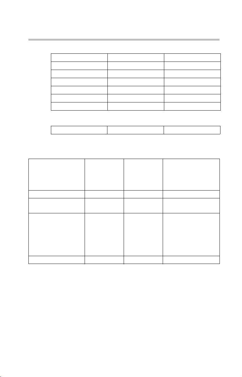
The following chart describes the Internet button/CD/DVD
button functionality.
41
Power is off or the
computer is in Hibernation
mode and you press the left
side of the Internet button/
CD/DVD button
Operating system is
running or the computer is
in Standby mode and you
press the left side of the
Internet button/CD/DVD
button
Power is off or the
computer is in Hibernation
mode and you press the
right side of the Internet
button/CD/DVD button
Operating system is
running or the computer is
in Standby mode and you
press the right side of the
Internet button/CD/DVD
button
The system accesses the Internet.
The system accesses the Internet.
If a CD is in the drive, the system operates
as a stand-alone CD player.
If a DVD is in the drive, the system
operates as a stand-alone DVD movie
player
If a CD is in the drive, the Windows
®
Media
Player starts and the audio CD
begins to play.
If a DVD is in the drive, WinDVD
and the DVD begins to play.
™
starts
The previous track button/next track button returns to the
preceding track on the disc (press the left side of the button)
or skips to the following track on the disc (press the right side
of the button).
The play/pause button starts playing the disc or makes it
pause if currently playing.
The stop button stops a disc that is currently playing.
Page 42

42
Using the Optical drive
Inserting a compact disc
Before putting on headphones to listen to an audio CD, turn the
volume dial down. Do not set the volume too high when using the
headphones. Continuous exposure to loud sound can harm your
hearing.
To insert a compact disc into the drive:
1 Make sure the computer is turned on.
2 Make sure the drive’s in-use indicator light is off.
3 Press the drive’s eject button.
The disc tray slides partially out of the drive (about 1 inch).
HINT: The drive will not open if the computer’s power is off.
4 Grasp the tray and pull it fully open.
5 Hold the disc by its edges and check that it is free of dust.
If the disc is dusty, clean it.
6 Place the disc carefully in the disc tray, label side up.
Sample positioning the disc in the drive
7 Gently press the disc onto the center spindle until it clicks
into place.
Handle DVDs and CDs carefully, making contact only with the center
hole and edge. Do not touch the surface of the disc. Do not stack
discs. If you incorrectly handle the discs, you could lose data.
Page 43

Using the Optical drive
8 Make sure the disc is completely on the spindle and is
lying flat on the tray.
If you insert the disc incorrectly, it may jam the drive. If this happens,
contact Toshiba support for assistance.
9 Push the disc tray in by pressing gently on the center of
the tray until it clicks into place.
You are ready to use the disc.
Removing a disc with the computer on
To remove a compact disc (CD or DVD) with the computer
turned on:
1 Press the eject button on the drive.
Do not press the eject button while the in-use indicator light is
glowing. Doing so could damage the disc or the drive.
Also, if the disc is still spinning when you open the disc tray, wait for
it to stop spinning before you remove it.
2 Pull the tray out until it is fully open, remove the disc,
and place it in its protective cover.
3 Gently push the tray in to close it.
43
Removing a disc with the computer off
1 Insert a slender object, such as a straightened paper clip,
into the manual eject hole.
The disc tray slides partially out of the drive (about 1 inch).
Never use a pencil to press the manual eject button. Pencil lead can
break off inside the computer and damage it.
2 Pull the tray out until it is fully open, remove the disc,
and place it in its protective cover.
3 Gently push the tray in to close it.
Page 44

44
Moving the computer
Moving the computer
Before moving your computer, even across the room, make
sure all disk activity has ended (the drive indicator light stops
glowing) and all external peripheral cables are disconnected.
Do not pick up the computer by its display panel or by the back
(where the ports are located). Doing so could damage the system.
Mobile computing
Running the computer on battery power
Battery life may vary considerably from specifications
depending on product model, configuration, applications,
power management settings and features utilized, as well as
the natural performance variations produced by the design of
individual components. Published battery life numbers are
achieved on select models and configurations tested by
Toshiba at the time of publication. Recharge time varies
depending on usage. Battery may not charge while the
computer is consuming full power.
After a period of time, the battery will lose its ability to
perform at maximum capacity and will need to be replaced.
This is normal for all batteries. To purchase a new battery
pack, see the accessories information that shipped with your
computer or visit the Toshiba Web site at
accessories.toshiba.com.
To ensure that the battery maintains its maximum capacity,
operate the computer on battery power at least once a month
until the battery is fully discharged. Please see “Maximizing
battery life” on page 49 for procedures. If the computer is
continuously operated on AC power, either through an AC
adapter or a docking station (if applicable to your system), for
an extended period (more than a month), the battery may fail
to retain a charge. This may shorten the life of the battery, and
the battery light may not indicate a low-battery condition.
The computer also has an internal real-time-clock (RTC)
battery.
Page 45

The RTC battery powers the RTC memory that stores your
system configuration settings and the current time and date
information. It maintains this information for up to a month
while the computer is turned off.
TECHNICAL NOTE: The RTC battery does not charge while the
computer is turned off, even when AC power is attached.
The RTC battery charges only while the computer is powered on.
Monitoring battery power
The computer’s main battery light gives you an indication of
the main battery’s current charge:
❖ Glows amber while the main battery is being charged
(AC adapter connected).
❖ Glows blue when the main battery is fully charged.
❖ Is unlit when the battery has discharged, the battery is not
charging, or the AC adapter is not plugged into the
computer or AC outlet.
Battery life and charge time may vary, depending upon power
management settings, applications and features used.
Mobile computing
45
Flashes amber when the main battery charge is low and it
❖
is time to recharge the main battery or plug in the AC
adapter.
HINT: Be careful not to confuse the battery light ( ) with the on/off
light ( ). When the on/off light flashes amber, it indicates that the
system is suspended (using the Windows
Standby command).
TECHNICAL NOTE: When your computer is using all of the power
provided by the AC Adapter to run applications, features, and
devices, the recharging of the battery cannot occur. Your computer's
Power Saver utility can be used to select a power level setting that
reduces the power required for system operation and will allow the
battery to recharge.
®
operating system
Page 46

46
Mobile computing
Setting battery alarms
Your computer can be configured to warn you when the
battery is running low. For more information, see “Setting
battery alarms” in the electronic user’s guide.
Changing the main battery
When your main battery has run out of power, you have two
options: plug in the AC adapter or install a fresh main battery.
Never short circuit the battery pack by either accidentally or
intentionally bringing the battery terminals in contact with another
conductive object. This could cause serious injury or fire, and could
also damage the battery pack.
Never expose a battery pack to abnormal shock, vibration or
pressure. The battery pack's internal protective device could fail,
causing it to overheat or ignite, resulting in caustic liquid leakage, or
explosion or fire, possibly resulting in death or serious injury.
TECHNICAL NOTE: To avoid losing any data, save your files and
then either completely shut down your computer, or put it into
Hibernation mode before changing the main battery.
Removing the battery from the computer
To remove the battery:
1 Save your work.
2 Turn off the computer or place it in Hibernation mode
according to the instructions in “Using and configuring
Hibernation mode” in the electronic user’s guide.
3 Unplug and remove any cables connected to the
computer, including the AC adapter.
4 Close the display panel and turn the computer upside
down.
Page 47

Mobile computing
5 Slide the battery release lock to the unlocked position.
Sample unlocking the battery release lock
6 Slide the battery release latch to release the battery.
7 Pull the discharged battery out of the computer.
47
Sample removing the battery
If the battery is leaking or its case is cracked, put on protective gloves
to handle it, and discard it immediately. Always dispose of used battery
packs in compliance with all applicable laws and regulations. Put
insulating tape, such as cellophane tape, on the electrode during
transportation to avoid a possible short circuit, fire or electric shock.
Failure to do so could possibly result in serious injury.
Inserting a charged battery
To insert a battery:
1 Wipe the terminals of the charged battery with a clean
cloth to ensure a good connection.
Page 48

48
Taking care of your battery
2 Insert the charged battery into the slot until the latch clicks.
The battery has been designed so that you cannot install it
with reverse polarity.
If the battery does not slide into the slot easily, move the battery
release lock to the unlocked position and try again. Do not force the
battery into position.
3 Slide the battery lock to the locked position.
4 Turn the computer right side up.
5 Reconnect any cables that were removed in step 3 of
“Removing the battery from the computer” on page 46.
6 Restart the computer.
Taking care of your battery
The following sections offer tips on how to take care of your
battery and prolong its life.
Battery safety precautions
❖ If the battery pack produces an odor, overheats or
changes color or shape while it is being used or charged,
turn off the computer’s power immediately and
disconnect the power cord/cable from the power socket.
Carefully remove the battery pack from the computer.
❖ Do not try to disassemble a battery pack.
❖ Do not overcharge or reverse charge a battery.
Overcharging will shorten its life, and reverse charging
could damage it.
❖ Avoid touching the metal terminals of the battery with
another metal object. Short-circuiting the battery can
cause it to overheat and may cause damage to the battery
or the computer.
❖ Do not incinerate a spent battery, as this could cause it to
explode and release caustic liquid.
❖ If a battery is leaking or damaged, replace it immediately.
Use protective gloves when handling a damaged battery.
Page 49

❖ To replace the main battery, use an identical battery that
you can purchase through the Toshiba Web site at
accessories.toshiba.com.
❖ A reverse polarity condition should be avoided with all
batteries. The main battery is designed so that it cannot
be installed in reverse polarity.
❖ Charge the battery only in the computer or in a battery
charger designated as an approved option.
❖ When you install the battery pack, you should hear a
click when it is seated properly.
❖ Do not expose the battery pack to fire. The battery pack
could explode.
Maximizing battery life
To maximize the life of your battery pack:
❖ At least once a month, disconnect the computer from a
power source and operate it on battery power until the
battery pack fully discharges. Before doing so, follow the
steps below:
1 Turn off the computer’s power.
Taking care of your battery
49
2 Disconnect the AC adapter and turn on the
computer’s power. If it does not turn on, go to step 4.
3 Operate the computer on battery power for five
minutes. If the battery pack has at least five minutes
of operating time, continue operating until the battery
pack is fully discharged. If the battery light flashes or
there is some other warning to indicate a low battery,
go to step 4.
4 Connect the AC adapter to the computer and connect
the power cord/cable to a power outlet. The DC-IN or
AC power-light should glow blue, and the battery
light should glow amber to indicate that the battery
pack is being charged. If the DC-IN or AC powerlight indicator does not glow, power is not being
supplied. Check the connections for the AC adapter
and power cord/cable.
5 Charge the battery pack until the battery light glows
blue.
❖ If you have extra battery packs, rotate their use.
Page 50

50
Taking care of your battery
❖ If you will not be using the system for an extended
period, more than one month, remove the battery pack.
❖ Disconnect the AC adapter when the battery is fully
charged. Overcharging makes the battery hot and
shortens its life.
❖ If you are not going to use the computer for more than
eight hours, disconnect the AC adapter.
❖ Store spare battery packs in a cool dry place out of direct
sunlight.
Disposing of used batteries
When a battery pack nears the end of its life, its ability to
hold a charge will decrease. When the battery pack needs to
be replaced, the main battery light flashes amber shortly after
you have fully recharged the battery.
You must discard a battery if it becomes damaged.
Never attempt to dispose of a battery pack by burning or by throwing
it into a fire, and never allow exposure to a heating apparatus (e.g.,
microwave oven). Heat can cause a battery pack to explode and
possibly cause serious injury.
Always dispose of used battery packs in compliance with all
applicable laws and regulations. Put insulating tape, such as
cellophane tape, on the electrode during transportation to avoid a
possible short circuit, fire or electric shock. Failure to do so could
possibly result in serious injury.
Always use the battery pack supplied as an accessory or an
equivalent battery pack specified in the User's Manual. Other battery
packs have different voltage and terminal polarities. Use of nonconforming battery packs could generate smoke or cause fire or
rupture, possibly resulting in serious injury.
After repeated use, batteries will finally lose their ability to
hold a charge and you will need to replace them. Under
certain applicable laws, it may be illegal to dispose of old
batteries by placing them in the trash.
Page 51

Please be kind to our shared environment. Check with your
local government authority for details regarding where to
recycle old batteries or how to dispose of them properly. If
you cannot find the information you need elsewhere, call
Toshiba at: (800) 457-7777.
If something goes wrong
Problems that are easy to fix
Your program stops responding.
If you are working with a program that suddenly freezes all
operations, chances are the program has stopped responding.
You can exit the failed program without shutting down the
operating system or closing other programs.
To close a program that has stopped responding:
1 Press
2 Click the Applications tab.
Ctrl, Alt, and Del simultaneously (once).
The Windows Task Manager window appears.
If a program has stopped responding, the words “not
responding” appear beside its name in the list.
If something goes wrong
51
3 Select the program you want to close, then click End
Tas k.
Closing the failed program should allow you to continue
working. If it does not, continue with the next step.
4 Close the remaining programs one by one by selecting
the program name, then End Task.
To power off your computer, do one of the following:
If you are not connected to a domain server:
1 Click Start, Turn off computer.
The Turn off computer window appears.
2 Click Turn O f f.
The computer turns off.
Page 52

52
If something goes wrong
If you are connected to a domain server:
1 Click Start, Shut down.
The Shut Down window appears.
2 Click Shut down from the drop-down list.
3 Click OK.
The computer shuts down completely.
Your program performs an illegal operation.
If you receive the message, “
operation
happens again, record the details of the message and consult
the software manufacturer.
To record the details:
1 Click the Details button and select the text the operating
2 Press
3 Open Notepad (click Start, All Programs, Accessories
4 Press
5 Add a paragraph break and type some notes describing
6 Save the file and refer to it when you contact the software
,” close the window and continue working. If it
system displays.
The Details button displays information that the software
manufacturer needs to help you solve your problem.
Ctrl and c simultaneously to copy the text to the
clipboard.
and then click Notepad).
Ctrl and v simultaneously to paste the details into
Notepad.
what you were doing when you received the message and
how the error can be reproduced.
manufacturer.
Your program has performed an illegal
Problems when you turn on the computer
These problems may occur when you turn on the power.
The computer will not start.
Make sure you attached the AC adapter and power cord/cable
properly or installed a charged battery.
Press and hold the power switch for at least 10 seconds.
Page 53

If something goes wrong
If you are using the AC adapter, check that the wall outlet is
working by plugging in another device, such as a lamp.
Verify that the computer is on by looking at the on/off
indicator. If the indicator is glowing, the computer is on.
If you are using an AC adapter, verify that the computer is
receiving power from the external power source by looking at
the AC power light. If the indicator is glowing, the computer
is connected to a live external power source.
The computer starts, but when you press a key nothing
happens.
Verify that the active program accepts text input. Try clicking
your mouse on an area where you can type text and try typing
again.
Your computer may be in Standby mode and have a software
or resource conflict. When this happens turning the power on
returns you to the problem instead of restarting the system.
To clear the condition, press
Clearing the condition may get the computer running, but it
will not solve a resource conflict. Read the documentation
that came with the conflicting device and “Resolving a
hardware conflict” in your electronic user’s guide.
The keyboard produces unexpected characters.
A keypad overlay may be on. If the numlock light or cursor
control mode light is on, press
turn off the cursor control mode light or
simultaneously to turn off the numlock light.
If the problem occurs when both the keypad overlays are off,
make sure the software you are using is not remapping the
keyboard. Refer to the software documentation and check
that the program does not assign different meanings to any of
the keys.
Ctrl, Alt, and Del simultaneously.
Fn and F10 simultaneously to
Fn and F11
53
Display problems
Here are some typical display problems and their solutions:
The screen is blank.
Display Auto Off may have gone into effect. Press any key to
activate the screen.
Page 54

54
If something goes wrong
You may have activated the instant password feature by
pressing
password, press any key, type the password and press
Fn and F1 simultaneously. If you have registered a
Enter. If
no password is registered, press any key. The screen
reactivates and allows you to continue working.
If you are using the built-in screen, make sure the display
priority is not set for an external monitor. To do this, press
F5 simultaneously (once). If this does not correct the
and
problem, press
Fn and F5 simultaneously again to return the
Fn
display priority to its previous setting.
HINT: Holding the Fn key and pressing the F5 key several times will
advance you through the display options.
If you are using an external monitor:
❖ Check that the monitor is turned on.
❖ Check that the monitor’s power cord/cable is firmly
plugged into a working power outlet.
❖ Check that the cable connecting the external monitor to
the computer is firmly attached.
❖ Try adjusting the contrast and brightness controls on the
external monitor.
❖ Press Fn and F5 simultaneously to make sure the display
priority is not set for the built-in screen.
Small bright dots appear on your TFT display when you
turn on your computer.
Small bright dots may appear on your screen display when
you turn on your PC. Your display contains an extremely
large number of thin-film transistors (TFT) and is
manufactured using high-precision technology. Any small
bright dots that may appear on your display are an intrinsic
characteristic of the TFT manufacturing technology. Over a
period of time, and depending on the usage of the computer,
the brightness of the screen will deteriorate. This is also an
intrinsic characteristic of the screen technology. When the
computer is operated on battery power, the screen will dim
and you may not be able to increase the brightness of the
screen while on battery power.
Page 55

PC Card problems
PC Card checklist
❖ Make sure the card is inserted properly into the slot.
See “Using PC Cards” in the electronic user’s guide for
information about how to insert PC Cards.
❖ Make sure all cables are securely connected.
❖ Occasionally a defective PC Card slips through quality
control. If another PCMCIA-equipped computer is
available, try the card in that machine. If the card
malfunctions again, it may be defective.
Resolving PC Card problems
Here are some common problems and their solutions:
The slot appears to be dead. PC Cards that used to work
no longer work.
Check the PC Card status:
1 Click Start.
2 Click My Computer icon with the secondary button,
then click Properties.
The System Properties dialog box appears.
If something goes wrong
55
3 Click the Hardware tab.
4 Click the Device Manager button.
5 Double-click the PCMCIA adapter.
6 Double-click the appropriate PC Card.
The operating system displays your PC Card’s Properties
dialog box, which contains information about your PC
Card configuration and status.
Page 56

56
If you need further assistance
The computer stops working (hangs) when you insert a
PC Card.
The problem may be caused by an I/O (input/output) conflict
between the PCMCIA socket and another device in the
system. Use Device Manager to make sure each device has its
own I/O base address. See “Fixing a problem with device
manager” in the electronic user’s guide for more information.
Since all PC Cards share the same socket, each card is not
required to have its own address.
If you need further assistance
If you have followed the recommendations in this section and
are still having problems, you may need additional technical
assistance. This section contains the steps to take to ask for
help.
Before you contact Toshiba
Since some problems may be related to the operating system
or the program you are using, it is important to investigate
other sources of assistance first.
Try the following before contacting Toshiba:
❖ Review the troubleshooting information in your
operating system documentation.
❖ If the problem occurs while you are running a program,
consult the program’s documentation for troubleshooting
suggestions. Contact the software company’s technical
support group for their assistance.
Detailed system specifications are available at
www.ts.toshiba.com by selecting your particular product and
model number, clicking GO, and then clicking the Detailed
Specs link from the menu on the left, or just refer to the
computer documentation shipped with your product.
For the number of a Toshiba dealer near you, see ”Toshiba
voice contact” in this section.
Page 57

Contacting Toshiba
If you still need help and suspect that the problem is
hardware-related, Toshiba offers a variety of resources to help
you.
Toshiba’s Technical Support Web site
For technical support, or to stay current on the most recent
software and hardware options for your computer, and for
other product information, be sure to regularly check the
Toshiba Web site at pcsupport.toshiba.com
Toshiba voice contact
Before calling Toshiba, make sure you have:
❖ Your computer’s serial number
❖ The computer and any optional devices related to the
problem
❖ Backup copies of your Windows
all other preloaded software on your choice of media
❖ Name and version of the program involved in the
problem along with its installation media
❖ Information about what you were doing when the
problem occurred
❖ Exact error messages and when they occurred
For technical support, call the Toshiba Global Support
Centre:
Within the United States at (800) 457-7777
Outside the United States at (949) 859-4273
If you need further assistance
.
®
operating system and
57
Page 58

58
Power cord/cable connectors
Power cord/cable connectors
Your computer features a universal power supply you can use
worldwide. This section shows the shapes of the typical AC
power cord/cable connectors for various parts of the world.
USA and Canada
(UL and CSA
approved)
United Kingdom
(BS approved)
Features and specifications
This section lists the computer’s features.Numbered legal
footnotes may also be found on page 65.
Product Series
The product specifications and configuration information are
designed for a product Series. Your particular model may not have
all the features and specifications listed or illustrated. For more
detailed information about the features and specifications on your
particular model, visit Toshiba’s Web site at pcsupport.toshiba.com.
While Toshiba has made every effort at the time of publication to
ensure the accuracy of the information provided herein, product
specifications, configurations, prices, system/component/options
availability are all subject to change without notice. For the most upto-date product information about your computer, or to stay current
with the various computer software or hardware options, visit
Toshiba’s Web site at pcsupport.toshiba.com.
1
Australia
(AS approved)
Europe
(VDA and
NEMKO approved)
Page 59

Technology and processor
Processor
Central Processing Unit)
Intel® Core™ Solo Processor T1300
(1.66 GHz, 2 MB L2 cache, 667 MHz FSB)
®
Core™ Duo Processor T2300
Intel
(1.66 GHz, 2 MB L2 cache, 667 MHz FSB)
®
Core™ Duo Processor T2400
Intel
(1.83 GHz, 2 MB L2 cache, 667 MHz FSB)
®
Core™ Duo Processor T2500
Intel
(2.00 GHz, 2 MB L2 cache, 667 MHz FSB)
®
Core™ Duo Processor T2600
Intel
(2.16 GHz, 2 MB L2 cache, 667 MHz FSB)*
*CPU performance in your computer product may vary from
specifications under the following conditions:
- use of certain external peripheral products
- use of battery power instead of AC power
- use of certain multimedia, computer generated graphics or
video applications
- use of standard telephone lines or low speed network
connections
- use of complex modeling software, such as high end
computer aided design applications
- use of several applications or functionalities simultaneously
- use of computer in areas with low air pressure (high altitude
>1,000 meters or >3,280 feet above sea level)
- use of computer at temperatures outside the range of 5° C to
30° C (41° F to 86° F) or >25° C (77° F) at high altitude (all
temperature references are approximate and may vary
depending on the specific computer model – please refer to
your Resource Guide, or visit the Toshiba website at
www.pcsupport.toshiba.com for details).
*CPU performance may also vary from specifications due
to design configuration.
Under some conditions, your computer product may automatically shut-down. This is a normal protective feature designed to
reduce the risk of lost data or damage to the product when used
outside recommended conditions. To avoid risk of lost data,
always make back-up copies of data by periodically storing it
on an external storage medium. Use your computer product
only under recommended conditions. Read additional restrictions under “Environmental Conditions” in your product
“Detailed Specs.” Contact Toshiba Technical Service and Support for more information.
Features and specifications
59
2
Page 60

60
Graphics
(Graphics Processing
Unit)
Features and specifications
®
Intel
Graphics Media Accelerator 950 or ATI Mobility™
®
Radeon
X1300* 3
*Graphics processor unit ("GPU") performance may vary
depending on product model, design configuration,
applications, power management settings and features utilized.
GPU performance is only optimized when operating in AC
power mode and may decrease considerably when operating in
battery power mode.
Power
Main battery Removable, rechargeable Lithium-Ion (Li-Ion) high-capacity
battery (10.8V x 4000 mAh 6-cell)*
*Battery life may vary considerably from specifications
depending on product model, configuration, applications,
power management settings and features utilized, as well
as the natural performance variations produced by the
design of individual components. Published battery life
numbers are achieved on select models and configurations
tested by Toshiba at the time of publication. See “Detailed
Specs” for specific battery measurement test. Recharge
time varies depending on usage. Battery may not charge
while computer is consuming full power. After a period of
time, the battery will lose its ability to perform at maximum capacity and will need to be replaced. This is normal
for all batteries. To purchase a new battery pack, see the
accessories information that shipped with your computer
or visit the Toshiba web site at
www.accessories.toshiba.com.
RTC battery Lithium-Ion (Li-Ion) or NiMH battery provides power for
the internal real-time clock and calendar
4
The RTC battery does not charge while the computer is turned off
even when the AC adapter is charging the computer.
Page 61

Features and specifications
61
Storage capacity
Hard Disk Drive (HDD)
Capacity
2.5-inch removable drive and controller provides non-vol-
atile storage for 40 GB, 60 GB, 80 GB, 100 GB, and
120 GB* 5
*1 Gigabyte (GB) means 10
9
= 1,000,000,000 bytes using
powers of 10. The computer operating system, however,
reports storage capacity using powers of 2 for the definition of 1 GB = 2
30
= 1,073,741,824 bytes, and therefore
shows less storage capacity. Available storage capacity
will also be less if the product includes one or more preinstalled operating systems, such as Microsoft Operating
System and/or pre-installed software applications, or
media content. Actual formatted capacity may vary.
Ports
S-Video out port Lets you play DVD video on a projector or TV that accepts S-
video inputs
DC-IN Lets you connect the computer to AC power, using the AC
Headphone jack Use the 3.5-mm headphone jack to connect stereo headphones
Microphone jack Use the 3.5-mm microphone stereo jack to connect an external
RGB (monitor) port Use the 15-pin, analog VGA port to connect an external SVGA
Modem port Use the modem port to connect the internal modem directly to
USB 2.0 ports Support USB 2.0 peripherals (4 ports)
LAN port Use the LAN port to connect to a LAN via an RJ45 connection
®
port The i.LINK® port (IEEE 1394) provides fast data transfer rates
i.LINK
PC Card slot The PC Card slot lets you install one Type II or Type I PC Card.
™
ExpressCard
Slot The ExpressCard™ slot supports the use of ExpressCard™
Bridge Media Adapter
Slot
adapter and power cord/cable
or other audio output devices
monaural microphone or other audio input device
monitor (color or monochrome)
a telephone line (purchased separately) via an RJ11 connection
(up to 400 Mbps)
Minimum slot thickness: 5 mm
media
The Bridge Media Adapter Slot can be used for additional storage via Secure Digital
Stick, Memory Stick PRO, or MultiMediaCards
™
Cards, xD-Picture Cards, Memory
™
Page 62

62
Features and specifications
Standard hardware
Memory (Main System) The system suppports 256 MB of RAM, up to 4096 MB of
RAM, depending on your configuration*
*Part of the main system memory may be used by the graphics
system for graphics performance and therefore reduce the
amount of main system memory available for other computing
activities. The amount of main system memory allocated to
support graphics may vary depending on the graphics system,
applications utilized, system memory size and other factors. For
PCs configured with 4 GB of system memory, the full system
memory space for computing activities will be considerably
less and will vary by model and system configuration.
Display 15.4-inch WXGA (measured diagonally) active matrix Thin
Film Transistor (TFT) color LCD displays up to 16 million colors at 1280 x 800 (native resolution), or WSXGA+ at 1680 x
7
1050.*
Available configurations are: normal and TruBrite (High
Brightness).
*Small bright dots may appear on your screen display when
you turn on your PC. Your display contains an extremely large
number of thin-film transistors (TFT) and is manufactured
using high-precision technology. Any small bright dots that
may appear on your display are an intrinsic characteristic of the
TFT manufacturing technology. Over a period of time, and
depending on the usage of the computer, the brightness of the
screen will deteriorate. This is also an intrinsic characteristic of
the screen technology. When the computer is operated on battery power, the screen will dim and you may not be able to
increase the brightness of the screen while on battery power.
Communication Integrated V.92 56K modem*
*Due to FCC limitations, speeds of 53 kbps are the maximum
permissible rates during downloads. Actual data transmission
speeds will vary depending on line conditions.
For more detailed information regarding your system’s modem,
visit the Toshiba Web site at toshiba.com.
Networking 10/100 Ethernet or 1 Gbps Ethernet LAN adapter with RJ45
Pointing device Standard TouchPad
Sound controller Realtek ALC861
connection
™
/Dual Mode Pad (optional) pointing
device provides the functionality of a mouse or other pointing
device
8
6
Page 63

Optical drive options
CD-RW/DVD-ROM
9
drive*
DVD SuperMulti
9
drive*
READ: CD-ROM (24x), DVD-ROM (8x)
WRITE: CD-R (24x), CD-RW (4x)
Compatibility: CD-ROM (read only), CD-R (read/write),
CD-RW (read/write), DVD-ROM (read only), DVD-R
(read only), DVD-RW (read only), DVD-RAM (read only)
READ: CD-ROM (24x), DVD-ROM (8x)
WRITE: CD-R (24x), CD-RW (4x), DVD-R (8x),
DVD-RW(4x), DVD+R (8x), DVD+RW (4x),
DVD+R (Double Layer (2.4x), DVD-RAM (5x)
Compatibility: CD-ROM (read only), CD-R (read/write),
CD-RW (read/write), DVD-ROM (read only), DVD-R
(read/ write), DVD-RW (read /write), DVD+R (read/write),
DVD+RW (read/write), DVD-RAM (read/write)
*Due to manufacturing and quality variations in third party
optical media (e.g., CD or DVD) or optical media players/
recorders, in certain cases, your Toshiba optical drive may not
record on certain optical media that bear the applicable logo, or
playback optical media recorded by other PCs or optical media
recorders. Additionally, certain optical media recorded on your
optical drive may not playback or operate properly on other
PCs or optical media players. These problems are not due to
any defect in your Toshiba PC or optical drive. Please refer to
your PC's product specification for listing of specific format
compatibilities.
Copy protection technology may also prevent or limit recording
or viewing of certain optical media.
Features and specifications
63
Page 64

64
Features and specifications
Wireless Communication
®
Wi-Fi
The computer may come with an optional integrated Wi-Fi®
wireless LAN mini PCI communication module providing
wireless LAN functions.*
*Wireless connectivity and some features may require you to
purchase additional software, external hardware or services.
Availability of public wireless LAN access points may be
limited. The transmission speed over the wireless LAN and the
distance over which wireless LAN can reach may vary
depending on surrounding electromagnetic environment,
obstacles, access point design and configuration, and client
design and software/hardware configurations. The actual
transmission speed will be lower than the theoretical maximum
speed. To use the Atheros SuperAG
function, if available, your client and access point must support
the corresponding feature. Performance of these functions may
vary depending on the format of data transmitted.
Toshiba recommends that Wi-Fi options be factory-installed at the
time of order.
10
™
or SuperG™ wireless
Page 65

Legal Footnotes
1. Product Series
The product specifications and configuration information are designed
for a product Series. Your particular model may not have all the
features and specifications listed or illustrated. For more detailed
information about the features and specifications on your particular
model, visit Toshiba's Web site at pcsupport.toshiba.com.
While Toshiba has made every effort at the time of publication to
ensure the accuracy of the information provided herein, product
specifications, configurations, prices, system/component/options
availability are all subject to change without notice. For the most upto-date product information about your computer, or to stay current
with the various computer software or hardware options, visit
Toshiba's Web site at pcsupport.toshiba.com.
2. Processor (Central Processing Unit)
CPU performance in your computer product may vary from
specifications under the following conditions:
❖ use of certain external peripheral products
❖ use of battery power instead of AC power
❖ use of certain multimedia, computer generated graphics or video
applications
❖ use of standard telephone lines or low speed network connections
❖ use of complex modeling software, such as high end computer
aided design applications
❖ use of several applications or functionalities simultaneously
❖ use of computer in areas with low air pressure (high altitude
>1,000 meters or >3,280 feet above sea level)
❖ use of computer at temperatures outside the range of 5° C to
30° C (41° F to 86° F) or >25° C (77° F) at high altitude (all
temperature references are approximate and may vary depending
on the specific computer model – please visit the Toshiba website
at www.pcsupport.toshiba.com for details).
CPU performance may also vary from specifications due to design
configuration.
Under some conditions, your computer product may automatically
shut-down. This is a normal protective feature designed to reduce the
risk of lost data or damage to the product when used outside
recommended conditions. To avoid risk of lost data, always make
back-up copies of data by periodically storing it on an external storage
medium. Use your computer product only under recommended
conditions. Read additional restrictions under “Environmental
Conditions” in your product “Detailed Specs.” Contact Toshiba
Technical Service and Support for more information.
3. Graphics (Graphics Processing Unit)
GPU performance may vary depending on product model, design
configuration, applications, power management settings and features
utilized. GPU performance is only optimized when operating in AC
power mode and may decrease considerably when operating in battery
power mode.
Legal Footnotes
65
Page 66

66
Legal Footnotes
4. Battery Life
Battery life may vary considerably from specifications depending on
product model, configuration, applications, power management
settings and features utilized, as well as the natural performance
variations produced by the design of individual components.
Published battery life numbers are achieved on select models and
configurations tested by Toshiba at the time of publication. See
“Detailed Specs” for specific battery measurement test. Recharge time
varies depending on usage. Battery may not charge while computer is
consuming full power. After a period of time, the battery will lose its
ability to perform at maximum capacity and will need to be replaced.
This is normal for all batteries. To purchase a new battery pack, see
the accessories information that shipped with your computer or visit
the Toshiba web site at www.accessories.toshiba.com.
5. Hard Disk Drive (HDD) Capacity
1 Gigabyte (GB) means 10
10. The computer operating system, however, reports storage capacity
using powers of 2 for the definition of 1 GB = 230 = 1,073,741,824
bytes, and therefore shows less storage capacity. Available storage
capacity will also be less if the product includes one or more preinstalled operating systems, such as Microsoft Operating System and/
or pre-installed software applications, or media content. Actual
formatted capacity may vary.
6. Memory (Main System)
Part of the main system memory may be used by the graphics system
for graphics performance and therefore reduce the amount of main
system memory available for other computing activities. The amount
of main system memory allocated to support graphics may vary
depending on the graphics system, applications utilized, system
memory size and other factors. For PCs configured with 4 GB of
system memory, the full system memory space for computing
activities will be considerably less and will vary by model and system
configuration.
7. Display
Small bright dots may appear on your screen display when you turn on
your PC. Your display contains an extremely large number of thinfilm transistors (TFT) and is manufactured using high-precision
technology. Any small bright dots that may appear on your display are
an intrinsic characteristic of the TFT manufacturing technology. Over
a period of time, and depending on the usage of the computer, the
brightness of the screen will deteriorate. This is also an intrinsic
characteristic of the screen technology. When the computer is
operated on battery power, the screen will dim and you may not be
able to increase the brightness of the screen while on battery power.
8. Modem Speed
Due to FCC limitations, speeds of 53 kbps are the maximum
permissible rates during downloads. Actual data transmission speeds
will vary depending on line conditions.
9
= 1,000,000,000 bytes using powers of
Page 67

Legal Footnotes
9. Optical Media
Due to manufacturing and quality variations in third party optical
media (e.g., CD or DVD) or optical media players/recorders, in certain
cases, your Toshiba optical drive may not record on certain optical
media that bear the applicable logo, or playback optical media
recorded by other PCs or optical media recorders. Additionally,
certain optical media recorded on your optical drive may not playback
or operate properly on other PCs or optical media players. These
problems are not due to any defect in your Toshiba PC or optical drive.
Please refer to your PC’s product specification for listing of specific
format compatibilities.
Copy protection technology may also prevent or limit recording or
viewing of certain optical media.
10. Wireless
Wireless connectivity and some features may require you to purchase
additional software, external hardware or services. Availability of
public wireless LAN access points may be limited. The transmission
speed over the wireless LAN and the distance over which wireless
LAN can reach may vary depending on surrounding electromagnetic
environment, obstacles, access point design and configuration, and
client design and software/hardware configurations. The actual
transmission speed will be lower than the theoretical maximum speed.
To use the Atheros SuperAG
available, your client and access point must support the corresponding
feature. Performance of these functions may vary depending on the
format of data transmitted.
™
or SuperG™ wireless function, if
67
Page 68

68
Index
A
AC adapter 28
AC power light 28
alarms low battery 46
B
battery
alarms
46
changing 46
installing 46, 47
real-time clock (RTC) 45
removing 46, 47
built-in features 58
buttons
Optical drive
40
C
CD/DVD button functionality 41
CD/DVDs
inserting
changing
main battery
computer
moving
setting up 31
computing tips 37
connecting
AC adapter
power cable 29
printer 30
critical applications 4
42
46
44
28
D
DC-IN 29
disc, positioning 42
display
screen is blank
53
E
error messages
program has performed an illegal
operation
52
F
FCC Notice “Declaration of
Conformity Information”
files
backing up
saving 37
37
I
Industry Canada requirement 5
inserting
PC Cards
installing
main battery
memory modules 31
internal drives 64
36
46
K
keyboard
not working
unexpected characters 53
53
L
lights
AC power
28
M
main battery
changing
removing 46
memory
adding
expansion slots 31
removing 35
memory module
46
31
4
Page 69

69
inserting 33
removing 32
monitor
not working
54
moving the computer 44
O
Optical drive
buttons
40
P
PC Card
checklist
computer stops working 56
inserting 36
problem solving 55
removing 37
port
specifications
power
cable
cable connectors 58
computer will not start 52
specifications 60
power devices 64
precautions 26, 29
printer
connecting
problem solving
computer hangs when PC Card
computer will not power up 52
contacting Toshiba 56, 57
display is blank 53
external monitor 54
illegal operation 52
keyboard
keyboard produces unexpected
PC Card slots appear dead 55
program not responding 51
protection of stored data 3
55
61
29
30
inserted
56
not responding
characters
53
53
R
real-time clock (RTC) battery 45
removing
disc with computer off
43
main battery 46
PC Cards 37
S
safety
precautions
26
screen
blank
53
secondary control button 39
setting
battery alarms
46
setting up
AC adapter
28
computer 31
specifications 58
ports 61
power 60
standard hardware 62
storage capacity 61
standard hardware, specifications 62
storage capacity, specifications 61
stored data protection 3
T
tips on computing 37
TouchPad
using
39
W
Web sites 57
wireless interoperability 8
Page 70

Page 71

Page 72

PMA500260012
03/06
 Loading...