


User’s Manual
TECRA A10/S10/P10/M10/
Satellite S300L/
Satellite Pro S300/S300L
Series

Table of Contents
Copyright. . . . . . . . . . . . . . . . . . . . . . . . . . . . . . . . . . . . . . . . . . . . . . . . . vi
Disclaimer . . . . . . . . . . . . . . . . . . . . . . . . . . . . . . . . . . . . . . . . . . . . . . . . vi
Trademarks . . . . . . . . . . . . . . . . . . . . . . . . . . . . . . . . . . . . . . . . . . . . . . . vi
FCC information . . . . . . . . . . . . . . . . . . . . . . . . . . . . . . . . . . . . . . . . . . . vii
EU Conformity Statement . . . . . . . . . . . . . . . . . . . . . . . . . . . . . . . . . . viii
VCCI Class B Information . . . . . . . . . . . . . . . . . . . . . . . . . . . . . . . . . . viii
Modem warning notice. . . . . . . . . . . . . . . . . . . . . . . . . . . . . . . . . . . . . viii
Japan regulations. . . . . . . . . . . . . . . . . . . . . . . . . . . . . . . . . . . . . . . . . . ix
Instructions for IC CS-03 certified equipment . . . . . . . . . . . . . . . . . . . xii
Notes for Users in Australia and New Zealand . . . . . . . . . . . . . . . . . xiii
Following information is only valid for EU-member States:. . . . . . . xvi
Disposing of the computer and the computer's batteries . . . . . . . . xvi
Optical disc drive safety instructions. . . . . . . . . . . . . . . . . . . . . . . . . xvii
International precautions. . . . . . . . . . . . . . . . . . . . . . . . . . . . . . . . . . . xxi
Preface
Conventions . . . . . . . . . . . . . . . . . . . . . . . . . . . . . . . . . . . . . . . . . . . . xxiii
General Precautions
Provide adequate ventilation. . . . . . . . . . . . . . . . . . . . . . . . . . . . . . . xxvi
Creating a computer-friendly environment . . . . . . . . . . . . . . . . . . . xxvii
Stress injury . . . . . . . . . . . . . . . . . . . . . . . . . . . . . . . . . . . . . . . . . . . . xxvii
Heat injury . . . . . . . . . . . . . . . . . . . . . . . . . . . . . . . . . . . . . . . . . . . . . . xxvii
Pressure or impact damage. . . . . . . . . . . . . . . . . . . . . . . . . . . . . . . xxviii
PC Card overheating . . . . . . . . . . . . . . . . . . . . . . . . . . . . . . . . . . . . xxviii
Mobile phones . . . . . . . . . . . . . . . . . . . . . . . . . . . . . . . . . . . . . . . . . xxviii
Instruction Manual for Safety and Comfort . . . . . . . . . . . . . . . . . . xxviii
Chapter 1 Getting Started
Equipment checklist. . . . . . . . . . . . . . . . . . . . . . . . . . . . . . . . . . . . . . . 1-1
Getting Started . . . . . . . . . . . . . . . . . . . . . . . . . . . . . . . . . . . . . . . . . . . 1-3
System Recovery Options . . . . . . . . . . . . . . . . . . . . . . . . . . . . . . . . . 1-12
System Recovery . . . . . . . . . . . . . . . . . . . . . . . . . . . . . . . . . . . . . . . . 1-13
User’s Manual ii

TECRA A10/S10/P10/M10/Satellite S300L/Satellite Pro S300/S300L
Chapter 2 The Grand Tour
Front with the display closed . . . . . . . . . . . . . . . . . . . . . . . . . . . . . . . 2-1
Left side. . . . . . . . . . . . . . . . . . . . . . . . . . . . . . . . . . . . . . . . . . . . . . . . . 2-2
Right side . . . . . . . . . . . . . . . . . . . . . . . . . . . . . . . . . . . . . . . . . . . . . . . 2-4
Back . . . . . . . . . . . . . . . . . . . . . . . . . . . . . . . . . . . . . . . . . . . . . . . . . . . . 2-6
Underside . . . . . . . . . . . . . . . . . . . . . . . . . . . . . . . . . . . . . . . . . . . . . . . 2-7
Front with the display open. . . . . . . . . . . . . . . . . . . . . . . . . . . . . . . . . 2-9
Indicators . . . . . . . . . . . . . . . . . . . . . . . . . . . . . . . . . . . . . . . . . . . . . . 2-12
Optical disc drives . . . . . . . . . . . . . . . . . . . . . . . . . . . . . . . . . . . . . . . 2-14
AC adaptor . . . . . . . . . . . . . . . . . . . . . . . . . . . . . . . . . . . . . . . . . . . . . 2-17
Chapter 3 Hardware, Utilities and Options
Hardware . . . . . . . . . . . . . . . . . . . . . . . . . . . . . . . . . . . . . . . . . . . . . . . . 3-1
Special features . . . . . . . . . . . . . . . . . . . . . . . . . . . . . . . . . . . . . . . . . . 3-6
TOSHIBA Value Added Package . . . . . . . . . . . . . . . . . . . . . . . . . . . . 3-10
Utilities and Applications. . . . . . . . . . . . . . . . . . . . . . . . . . . . . . . . . . 3-11
Optional devices. . . . . . . . . . . . . . . . . . . . . . . . . . . . . . . . . . . . . . . . . 3-16
Bridge media slot . . . . . . . . . . . . . . . . . . . . . . . . . . . . . . . . . . . . . . . . 3-22
Optional accessories . . . . . . . . . . . . . . . . . . . . . . . . . . . . . . . . . . . . . 3-39
Chapter 4 Operating Basics
TOSHIBA Dual Pointing Device. . . . . . . . . . . . . . . . . . . . . . . . . . . . . . 4-1
Using the Fingerprint Sensor . . . . . . . . . . . . . . . . . . . . . . . . . . . . . . . 4-3
Web Camera . . . . . . . . . . . . . . . . . . . . . . . . . . . . . . . . . . . . . . . . . . . . 4-10
Using the TOSHIBA Face Recognition . . . . . . . . . . . . . . . . . . . . . . . 4-11
Using optical disc drives . . . . . . . . . . . . . . . . . . . . . . . . . . . . . . . . . . 4-14
Writing CDs on DVD-ROM&CD-R/RW drives . . . . . . . . . . . . . . . . . . 4-18
Writing CD/DVDs on DVD Super Multi drives . . . . . . . . . . . . . . . . . 4-20
Media care . . . . . . . . . . . . . . . . . . . . . . . . . . . . . . . . . . . . . . . . . . . . . . 4-26
Sound System. . . . . . . . . . . . . . . . . . . . . . . . . . . . . . . . . . . . . . . . . . . 4-27
Modem . . . . . . . . . . . . . . . . . . . . . . . . . . . . . . . . . . . . . . . . . . . . . . . . . 4-30
Wireless communications . . . . . . . . . . . . . . . . . . . . . . . . . . . . . . . . . 4-33
LAN . . . . . . . . . . . . . . . . . . . . . . . . . . . . . . . . . . . . . . . . . . . . . . . . . . . 4-37
Computer Handling . . . . . . . . . . . . . . . . . . . . . . . . . . . . . . . . . . . . . . 4-39
Using the Hard Disk Drive (HDD) Protection . . . . . . . . . . . . . . . . . . 4-40
Using the TOSHIBA USB Sleep and Charge Utility . . . . . . . . . . . . . 4-42
Heat dispersal . . . . . . . . . . . . . . . . . . . . . . . . . . . . . . . . . . . . . . . . . . . 4-44
Chapter 5 The Keyboard
Typewriter keys. . . . . . . . . . . . . . . . . . . . . . . . . . . . . . . . . . . . . . . . . . . 5-1
Function keys: F1 … F12 . . . . . . . . . . . . . . . . . . . . . . . . . . . . . . . . . . . 5-2
Soft keys: FN key combinations . . . . . . . . . . . . . . . . . . . . . . . . . . . . . 5-2
Hot keys. . . . . . . . . . . . . . . . . . . . . . . . . . . . . . . . . . . . . . . . . . . . . . . . . 5-3
Windows special keys . . . . . . . . . . . . . . . . . . . . . . . . . . . . . . . . . . . . . 5-5
Keypad overlay . . . . . . . . . . . . . . . . . . . . . . . . . . . . . . . . . . . . . . . . . . . 5-6
Generating ASCII characters. . . . . . . . . . . . . . . . . . . . . . . . . . . . . . . . 5-7
User’s Manual iii

TECRA A10/S10/P10/M10/Satellite S300L/Satellite Pro S300/S300L
Chapter 6 Power and Power-Up Modes
Power conditions . . . . . . . . . . . . . . . . . . . . . . . . . . . . . . . . . . . . . . . . . 6-1
Monitoring of power condition . . . . . . . . . . . . . . . . . . . . . . . . . . . . . . 6-2
Battery . . . . . . . . . . . . . . . . . . . . . . . . . . . . . . . . . . . . . . . . . . . . . . . . . . 6-3
TOSHIBA Password Utility. . . . . . . . . . . . . . . . . . . . . . . . . . . . . . . . . 6-10
Power-up modes. . . . . . . . . . . . . . . . . . . . . . . . . . . . . . . . . . . . . . . . . 6-13
Panel power on/off . . . . . . . . . . . . . . . . . . . . . . . . . . . . . . . . . . . . . . . 6-13
System automatic Sleep/Hibernation . . . . . . . . . . . . . . . . . . . . . . . . 6-13
Chapter 7 HW Setup
Accessing HW Setup . . . . . . . . . . . . . . . . . . . . . . . . . . . . . . . . . . . . . . 7-1
HW Setup window . . . . . . . . . . . . . . . . . . . . . . . . . . . . . . . . . . . . . . . . 7-1
Chapter 8 Troubleshooting
Problem solving process. . . . . . . . . . . . . . . . . . . . . . . . . . . . . . . . . . . 8-1
Hardware and system checklist . . . . . . . . . . . . . . . . . . . . . . . . . . . . . 8-3
TOSHIBA support . . . . . . . . . . . . . . . . . . . . . . . . . . . . . . . . . . . . . . . . 8-29
Appendix A Specifications
Physical Dimensions . . . . . . . . . . . . . . . . . . . . . . . . . . . . . . . . . . . . . . A-1
Environmental Requirements . . . . . . . . . . . . . . . . . . . . . . . . . . . . . . . A-1
Appendix B Display Controller and Video mode
Display controller . . . . . . . . . . . . . . . . . . . . . . . . . . . . . . . . . . . . . . . . . B-1
Video mode . . . . . . . . . . . . . . . . . . . . . . . . . . . . . . . . . . . . . . . . . . . . . . B-1
Appendix C Wireless LAN
Card Specifications . . . . . . . . . . . . . . . . . . . . . . . . . . . . . . . . . . . . . . . C-1
Radio Characteristics. . . . . . . . . . . . . . . . . . . . . . . . . . . . . . . . . . . . . . C-2
Supported Frequency Sub-bands. . . . . . . . . . . . . . . . . . . . . . . . . . . . C-3
Appendix D Bluetooth wireless technology Interoperability
Bluetooth wireless technology and your Health . . . . . . . . . . . . . . . . D-2
Regulatory statements. . . . . . . . . . . . . . . . . . . . . . . . . . . . . . . . . . . . . D-2
Using Bluetooth Adaptor from TOSHIBA equipment in Japan . . . . D-4
Appendix E AC Power Cord and Connectors
Certification agencies . . . . . . . . . . . . . . . . . . . . . . . . . . . . . . . . . . . . . E-1
Appendix F TOSHIBA Anti-theft Protection Timer
Appendix G TOSHIBA PC Health Monitor
Starting the TOSHIBA PC Health Monitor. . . . . . . . . . . . . . . . . . . . . . G-2
If a TOSHIBA PC Health Monitor message is displayed. . . . . . . . . . G-2
Cleaning the cooling module . . . . . . . . . . . . . . . . . . . . . . . . . . . . . . . G-3
Appendix H Legal Footnotes
Non-applicable Icons*1 . . . . . . . . . . . . . . . . . . . . . . . . . . . . . . . . . . . . H-1
CPU*2. . . . . . . . . . . . . . . . . . . . . . . . . . . . . . . . . . . . . . . . . . . . . . . . . . . H-1
Memory (Main System)*3 . . . . . . . . . . . . . . . . . . . . . . . . . . . . . . . . . . . H-2
User’s Manual iv

TECRA A10/S10/P10/M10/Satellite S300L/Satellite Pro S300/S300L
Battery Life*4 . . . . . . . . . . . . . . . . . . . . . . . . . . . . . . . . . . . . . . . . . . . . H-3
Hard Disk Drive (HDD) Capacity*5 . . . . . . . . . . . . . . . . . . . . . . . . . . . H-3
LCD*6. . . . . . . . . . . . . . . . . . . . . . . . . . . . . . . . . . . . . . . . . . . . . . . . . . . H-3
Graphics Processor Unit ("GPU")*7 . . . . . . . . . . . . . . . . . . . . . . . . . . H-3
Wireless LAN*8 . . . . . . . . . . . . . . . . . . . . . . . . . . . . . . . . . . . . . . . . . . . H-4
Copy Protection*9 . . . . . . . . . . . . . . . . . . . . . . . . . . . . . . . . . . . . . . . . H-4
Images*10 . . . . . . . . . . . . . . . . . . . . . . . . . . . . . . . . . . . . . . . . . . . . . . . H-4
Glossary
Index
User’s Manual v

Copyright
Disclaimer
TECRA A10/S10/P10/M10/Satellite S300L/Satellite Pro S300/S300L
© 2009 by TOSHIBA Corporation. All rights reserved. Under the copyright
laws, this manual cannot be reproduced in any form without the prior
written permission of TOSHIBA. No patent liability is assumed, with respect
to the use of the information contained herein.
TOSHIBA TECRA A10/S10/P10/M10/Satellite S300L/Satellite Pro
S300/S300L Portable Personal Computer User’s Manual
First edition July 2009
Copyright authority for music, movies, computer programs, databases and
other intellectual property covered by copyright laws belongs to the author
or to the copyright owner. Copyrighted material can be reproduced only for
personal use or use within the home. Any other use beyond that stipulated
above (including conversion to digital format, alteration, transfer of copied
material and distribution on a network) without the permission of the
copyright owner is a violation of copyright or author's rights and is subject to
civil damages or criminal action. Please comply with copyright laws in
making any reproduction from this manual.
This manual has been validated and reviewed for accuracy. The
instructions and descriptions it contains are accurate for the TOSHIBA
TECRA A10/S10/P10/M10/Satellite S300L/Satellite Pro S300/S300L
Portable Personal Computer at the time of this manual’s production.
However, succeeding computers and manuals are subject to change
without notice. TOSHIBA assumes no liability for damages incurred directly
or indirectly from errors, omissions or discrepancies between the computer
and the manual.
Trademarks
IBM is a registered trademark and IBM PC is a trademark of International
Business Machines Corporation.
Intel, Intel SpeedStep, Intel Core and Centrino are trademarks or registered
trademarks of Intel Corporation.
Windows, Microsoft and Windows logo are registered trademarks of
Microsoft Corporation.
Bluetooth is a trademark owned by its proprietor and used by TOSHIBA
under license.
Photo CD is a trademark of Eastman Kodak Company.
Memory Stick, Memory Stick PRO, Memory Stick PRO Duo and i.LINK are
trademarks or registered trademarks of Sony Corporation.
ConfigFree is a trademark of Toshiba Corporation.
Wi-Fi is a registered trademark of the Wi-Fi Alliance.
Secure Digital and SD are trademarks of SD Card Association.
User’s Manual vi

TECRA A10/S10/P10/M10/Satellite S300L/Satellite Pro S300/S300L
MultiMediaCard and MMC are trademarks of MultiMediaCard Association.
xD-Picture Card is a trademark of FUJIFILM Corporation.
Other trademarks and registered trademarks not listed above may be used
in this manual.
FCC information
FCC notice "Declaration of Conformity Information"
This equipment has been tested and found to comply with the limits for a
Class B digital device, pursuant to part 15 of the FCC rules. These limits
are designed to provide reasonable protection against harmful interference
in a residential installation. This equipment generates, uses and can radiate
radio frequency energy and, if not installed and used in accordance with the
instructions, may cause harmful interference to radio communications.
However, there is no guarantee that interference will not occur in a
particular installation. If this equipment does cause harmful interference to
radio or television reception, which can be determined by turning the
equipment off and on, the user is encouraged to try to correct the
interference by one or more of the following measures:
■ Reorient or relocate the receiving antenna.
■ Increase the separation between the equipment and receiver.
■ Connect the equipment into an outlet on a circuit different from that to
which the receiver is connected.
■ Consult the dealer or an experienced radio/TV technician for help.
Only peripherals complying with the FCC class B limits may be attached to
this equipment. Operation with non-compliant peripherals or peripherals
not recommended by TOSHIBA is likely to result in interference to radio
and TV reception. Shielded cables must be used between the external
devices and the computer’s external monitor port, Universal Serial Bus
(USB 2.0) ports, eSATA/USB combo port, i.LINK® (IEEE1394) port, serial
port and microphone jack. Changes or modifications made to this
equipment, not expressly approved by TOSHIBA or parties authorized by
TOSHIBA could void the user’s authority to operate the equipment.
FCC conditions
This device complies with part 15 of the FCC Rules. Operation is subject to
the following two conditions:
1. This device may not cause harmful interference.
2. This device must accept any interference received, including
interference that may cause undesired operation.
User’s Manual vii
TECRA A10/S10/P10/M10/Satellite S300L/Satellite Pro S300/S300L
Contact
Address: TOSHIBA America Information Systems, Inc.
9740 Irvine Boulevard
Irvine, California 92618-1697
Telephone: (949) 583-3000
EU Conformity Statement
This product and - if applicable - the supplied accessories too are marked
with "CE" and comply therefore with the applicable harmonized European
standards listed under the Low Voltage Directive 2006/95/EC, the EMC
Directive 2004/108/EC and/or R&TTE Directive 1999/5/EC.
Responsible for CEmarking:
Manufacturer: Toshiba Corporation, 1-1 Shibaura 1-chome,
The complete official EU CE Declaration can be obtained on following
internet page:
http://epps.toshiba-teg.com/
TOSHIBA EUROPE GMBH, Hammfelddamm 8,
41460 Neuss, Germany.
Minato-ku, Tokyo, 105-8001, Japan
VCCI Class B Information
Modem warning notice
This information is applicable to the models equipped with a built-in
modem.
User’s Manual viii

TECRA A10/S10/P10/M10/Satellite S300L/Satellite Pro S300/S300L
Conformity Statement
The equipment has been approved to [Commission Decision "CTR21"] for
pan-European single terminal connection to the Public Switched Telephone
Network (PSTN).
However, due to differences between the individual PSTNs provided in
different countries/regions the approval does not, of itself, give an
unconditional assurance of successful operation on every PSTN network
termination point.
In the event of problems, you should contact your equipment supplier in the
first instance.
Network Compatibility Statement
This product is designed to work with, and is compatible with the following
networks. It has been tested to and found to conform with the additional
requirements conditional in EG 201 121.
Germany ATAAB AN005,AN006,AN007,AN009,AN010
and DE03,04,05,08,09,12,14,17
Greece ATAAB AN005,AN006 and GR01,02,03,04
Portugal ATAAB AN001,005,006,007,011 and
Spain ATAAB AN005,007,012, and ES01
Switzerland ATAAB AN002
All other countries/regions ATAAB AN003,004
Specific switch settings or software setup are required for each network,
please refer to the relevant sections of the user guide for more details.
The hookflash (timed break register recall) function is subject to separate
national type approvals. It has not been tested for conformity to national
type regulations, and no guarantee of successful operation of that specific
function on specific national networks can be given.
P03,04,08,10
Japan regulations
Region selection
If you are using the computer in Japan, technical regulations described in
the Telecommunications Business Law require that you select the Japan
region mode. It is illegal to use the modem in Japan with any other
selection.
Redial
Up to two redial attempts can be made. If more than two redial attempts are
made, the modem will return Black Listed. If you are experiencing
problems with the Black Listed code, set the interval between redials at one
minute or longer.
User’s Manual ix
TECRA A10/S10/P10/M10/Satellite S300L/Satellite Pro S300/S300L
Japan’s Telecommunications Business Law permits up to two redials on
analogue telephones, but the redials must be made within a total of three
minutes.
The internal modem is approved by Japan Approvals Institute for
Telecommunications Equipment.
A05-0413001
This label is located on the module.
Pursuant to FCC CFR 47, Part 68:
When you are ready to install or use the modem, call your local telephone
company and give them the following information:
■ The telephone number of the line to which you will connect the modem
■ The registration number that is located on the device
The FCC registration number of the modem will be found on either the
device which is to be installed, or, if already installed, on the bottom of
the computer outside of the main system label.
■ The Ringer Equivalence Number (REN) of the modem, which can vary.
For the REN of your modem, refer to your modem’s label.
The modem connects to the telephone line by means of a standard jack
called the USOC RJ11C.
User’s Manual x

TECRA A10/S10/P10/M10/Satellite S300L/Satellite Pro S300/S300L
Type of service
Your modem is designed to be used on standard-device telephone lines.
Connection to telephone company-provided coin service (central office
implemented systems) is prohibited. Connection to party lines service is
subject to state tariffs. If you have any questions about your telephone line,
such as how many pieces of equipment you can connect to it, the
telephone company will provide this information upon request.
Telephone company procedures
The goal of the telephone company is to provide you with the best service it
can. In order to do this, it may occasionally be necessary for them to make
changes in their equipment, operations, or procedures. If these changes
might affect your service or the operation of your equipment, the telephone
company will give you notice in writing to allow you to make any changes
necessary to maintain uninterrupted service.
If problems arise
If any of your telephone equipment is not operating properly, you should
immediately remove it from your telephone line, as it may cause harm to
the telephone network. If the telephone company notes a problem, they
may temporarily discontinue service. When practical, they will notify you in
advance of this disconnection. If advance notice is not feasible, you will be
notified as soon as possible. When you are notified, you will be given the
opportunity to correct the problem and informed of your right to file a
complaint with the FCC. In the event repairs are ever needed on your
modem, they should be performed by TOSHIBA Corporation or an
authorized representative of TOSHIBA Corporation.
Disconnection
If you should ever decide to permanently disconnect your modem from its
present line, please call the telephone company and let them know of this
change.
Fax branding
The Telephone Consumer Protection Act of 1991 makes it unlawful for any
person to use a computer or other electronic device to send any message
via a telephone fax machine unless such message clearly contains in a
margin at the top or bottom of each transmitted page or on the first page of
the transmission, the date and time it is sent and an identification of the
business, other entity or individual sending the message and the telephone
number of the sending machine or such business, other entity or individual.
In order to program this information into your fax modem, you should
complete the setup of your fax software before sending messages.
Use only No. 26AWG or larger modular cable.
User’s Manual xi
TECRA A10/S10/P10/M10/Satellite S300L/Satellite Pro S300/S300L
Instructions for IC CS-03 certified equipment
1. The Industry Canada label identifies certified equipment. This
certification means that the equipment meets certain
telecommunications network protective, operational and safety
requirements as prescribed in the appropriate Terminal Equipment
Technical Requirements document(s). The Department does not
guarantee the equipment will operate to the user’s satisfaction.
Before installing this equipment, users should ensure that it is
permissible to be connected to the facilities of the local
telecommunications company. The equipment must also be installed
using an acceptable method of connection.
The customer should be aware that compliance with the above
conditions may not prevent degradation of service in some situations.
Repairs to certified equipment should be coordinated by a
representative designated by the supplier. Any repairs or alterations
made by the user to this equipment, or equipment malfunctions, may
give the telecommunications company cause to request the user to
disconnect the equipment.
Users should ensure for their own protection that the electrical ground
connections of the power utility, telephone lines and internal metallic
water pipe systems, if present, are connected together. This precaution
may be particularly important in rural areas.
Users should not attempt to make such connections themselves, but
should contact the appropriate electric inspection authority, or electrician,
as appropriate.
2. The user manual of analog equipment must contain the equipment’s
Ringer Equivalence Number (REN) and an explanation notice similar to
the following:
The Ringer Equivalence Number (REN) of the modem, which can vary.
For the REN of your modem, refer to your modem’s label.
The Ringer Equivalence Number (REN) assigned to each terminal device
provides an indication of the maximum number of terminals allowed to be
connected to a telephone interface. The termination on an interface may
consist of any combination of devices subject only to the requirement that
the sum of the Ringer Equivalence Numbers of all the devices does not
exceed 5.
3. The standard connecting arrangement (telephone jack type) for this
equipment is jack type(s): USOC RJ11C.
The IC registration number of the modem is shown below.
Canada: 4005B-DELPHI
User’s Manual xii

TECRA A10/S10/P10/M10/Satellite S300L/Satellite Pro S300/S300L
Notes for Users in Australia and New Zealand
Modem warning notice for Australia
Modems connected to the Australian telecoms network must have a valid
Austel permit. This modem has been designed to specifically configure to
ensure compliance with Austel standards when the country/region selection
is set to Australia. The use of other country/region setting while the modem
is attached to the Australian PSTN would result in you modem being
operated in a non-compliant manner. To verify that the country/region is
correctly set, enter the command ATI which displays the currently active
setting.
To set the country/region permanently to Australia, enter the following
command sequence:
AT%T E=1
ATS133=1
AT&F
AT&W
AT%T E=0
ATZ
Failure to set the modem to the Australia country/region setting as shown
above will result in the modem being operated in a non-compliant manner.
Consequently, there would be no permit in force for this equipment and the
Telecoms Act 1991 prescribes a penalty of $12,000 for the connection of
non-permitted equipment.
Notes for use of this device in New Zealand
■ The grant of a Telepermit for a device in no way indicates Telecom
acceptance of responsibility for the correct operation of that device
under all operating conditions. In particular the higher speeds at which
this modem is capable of operating depend on a specific network
implementation which is only one of many ways of delivering high
quality voice telephony to customers. Failure to operate should not be
reported as a fault to Telecom.
■ In addition to satisfactory line conditions a modem can only work
properly if:
a/ it is compatible with the modem at the other end of the call and.
b/ the application using the modem is compatible with the application
at the other end of the call - e.g., accessing the Internet requires
suitable software in addition to a modem.
■ This equipment shall not be used in any manner which could constitute
a nuisance to other Telecom customers.
User’s Manual xiii

TECRA A10/S10/P10/M10/Satellite S300L/Satellite Pro S300/S300L
■ Some parameters required for compliance with Telecom’s PTC
Specifications are dependent on the equipment (PC) associated with
this modem. The associated equipment shall be set to operate within
the following limits for compliance with Telecom Specifications:
a/ There shall be no more than 10 call attempts to the same number
within any 30 minute period for any single manual call initiation, and
b/ The equipment shall go on-hook for a period of not less than 30
seconds between the end of one attempt and the beginning of the
next.
c/ Automatic calls to different numbers shall be not less than 5
seconds apart.
■ Immediately disconnect this equipment should it become physically
damaged, and arrange for its disposal or repair.
■ The correct settings for use with this modem in New Zealand are as
follows:
ATB0 (CCITT operation)
AT&G2 (1800 Hz guard tone)
AT&P1 (Decadic dialing make-break ratio =33%/67%)
ATS0=0 (not auto answer)
ATS6=4 (Blind dial delay)
ATS7=less than 90 (Time to wait to carrier after dialing)
ATS10=less than 150 (loss of carrier to hangup delay, factory
default of 15 recommended)
ATS11=90 (DTMF dialing on/off duration=90 ms)
ATX2 (Dial tone detect, but not (U.S.A.) call progress detect)
■ When used in the Auto Answer mode, the S0 register must be set with a
value of 3 or 4. This ensures:
■ a person calling your modem will hear a short burst of ringing before
the modem answers. This confirms that the call has been
successfully switched through the network.
■ caller identification information (which occurs between the first and
second ring cadences) is not destroyed.
■ The preferred method of dialing is to use DTMF tones (ATDT...) as this
is faster and more reliable than pulse (decadic) dialing. If for some
reason you must use decadic dialing, your communications program
must be set up to record numbers using the following translation table
as this modem does not implement the New Zealand “Reverse Dialing”
standard.
Number to be dialed: 0 1 2 3 4 5 6 7 8 9
Number to program into computer: 0 9 8 7 6 5 4 3 2 1
Note that where DTMF dialing is used, the numbers should be
entered normally.
User’s Manual xiv

TECRA A10/S10/P10/M10/Satellite S300L/Satellite Pro S300/S300L
■ The transmit level from this device is set at a fixed level and because of
this there may be circumstances where the performance is less than
optimal. Before reporting such occurrences as faults, please check the
line with a standard Telepermitted telephone, and only report a fault if
the phone performance is impaired.
■ It is recommended that this equipment be disconnected from the
Telecom line during electrical storms.
■ When relocating the equipment, always disconnect the Telecom line
connection before the power connection, and reconnect the power first.
■ This equipment may not be compatible with Telecom Distinctive Alert
cadences and services such as FaxAbility.
NOTE THAT FAULT CALLOUTS CAUSED BY ANY OF THE ABOVE
CAUSES MAY INCUR A CHARGE FROM TELECOM
General conditions
As required by PTC 100, please ensure that this office is advised of any
changes to the specifications of these products which might affect
compliance with the relevant PTC Specifications.
The grant of this Telepermit is specific to the above products with the
marketing description as stated on the Telepermit label artwork. The
Telepermit may not be assigned to other parties or other products without
Telecom approval.
A Telepermit artwork for each device is included from which you may
prepare any number of Telepermit labels subject to the general instructions
on format, size and color on the attached sheet.
The Telepermit label must be displayed on the product at all times as proof
to purchasers and service personnel that the product is able to be
legitimately connected to the Telecom network.
The Telepermit label may also be shown on the packaging of the product
and in the sales literature, as required in PTC 100.
The charge for a Telepermit assessment is $337.50. An additional charge
of $337.50 is payable where an assessment is based on reports against
non-Telecom New Zealand Specifications. $112.50 is charged for each
variation when submitted at the same time as the original.
An invoice for $NZ1237.50 will be sent under separate cover.
User’s Manual xv
TECRA A10/S10/P10/M10/Satellite S300L/Satellite Pro S300/S300L
Following information is only valid for EU-member States:
Disposal of products
The crossed out wheeled dust bin symbol indicates that products must be
collected and disposed of separately from household waste. Integrated
batteries and accumulators can be disposed of with the product. They will
be separated at the recycling centres.
The black bar indicates that the product was placed on the market after
August 13, 2005.
By participating in separate collection of products and batteries, you will
help to assure the proper disposal of products and batteries and thus help
to prevent potential negative consequences for the environment and
human health.
For more detailed information about the collection and recycling
programmes available in your country, please visit our website
(http://eu.computers.toshiba-europe.com) or contact your local city office or
the shop where you purchased the product.
Disposal of batteries and/or accumulators
The crossed out wheeled dust bin symbol indicates that batteries and/or
accumulators must be collected and disposed of separately from
household waste.
If the battery or accumulator contains more than the specified values of
lead (Pb), mercury (Hg), and/or cadmium (Cd) defined in the Battery
Directive (2006/66/EC), then the chemical symbols for lead (Pb), mercury
(Hg) and/or cadmium (Cd) will appear below the crossed out wheeled dust
bin symbol.
By participating in separate collection of batteries, you will help to assure
the proper disposal of products and batteries and thus help to prevent
potential negative consequences for the environment and human health.
For more detailed information about the collection and recycling
programmes available in your country, please visit our website
(http://eu.computers.toshiba-europe.com) or contact your local city office or
the shop where you purchased the product.
These symbols may not stick depending on the country and region where
you purchased.
Disposing of the computer and the computer's batteries
■ Discard this computer in accordance with applicable laws and
regulations. For further information, contact your local government.
■ This computer contains rechargeable batteries. After repeated use, the
batteries will finally lose their ability to hold a charge and you will need
to replace them. Under certain applicable laws and regulation, it may be
illegal to dispose of old batteries by placing them in the trash.
■ Please be kind to our shared environment. Check with your local
government authority for details regarding where to recycle old batteries
or how to dispose of them properly. This product contains mercury.
Disposal of this material may be regulated due to environmental
considerations. For disposal, reuse or recycling information, please
contact your local government.
User’s Manual xvi
TECRA A10/S10/P10/M10/Satellite S300L/Satellite Pro S300/S300L
Optical disc drive safety instructions
Be sure to check the international precautions at the end of this section.
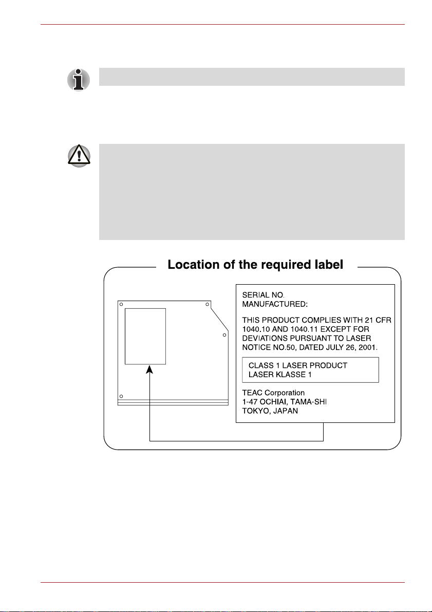
TEAC
DVD-ROM drive DV-28S
■ The DVD-ROM drive model employs a laser system. To ensure proper
use of this product, please read this instruction manual carefully and
retain for future reference. Should the unit ever require maintenance,
contact an authorized service location.
■ Use of controls, adjustments or the performance of procedures other
than those specified may result in hazardous radiation exposure.
■ To prevent direct exposure to the laser beam, do not try to open the
enclosure.
User’s Manual xvii
TECRA A10/S10/P10/M10/Satellite S300L/Satellite Pro S300/S300L
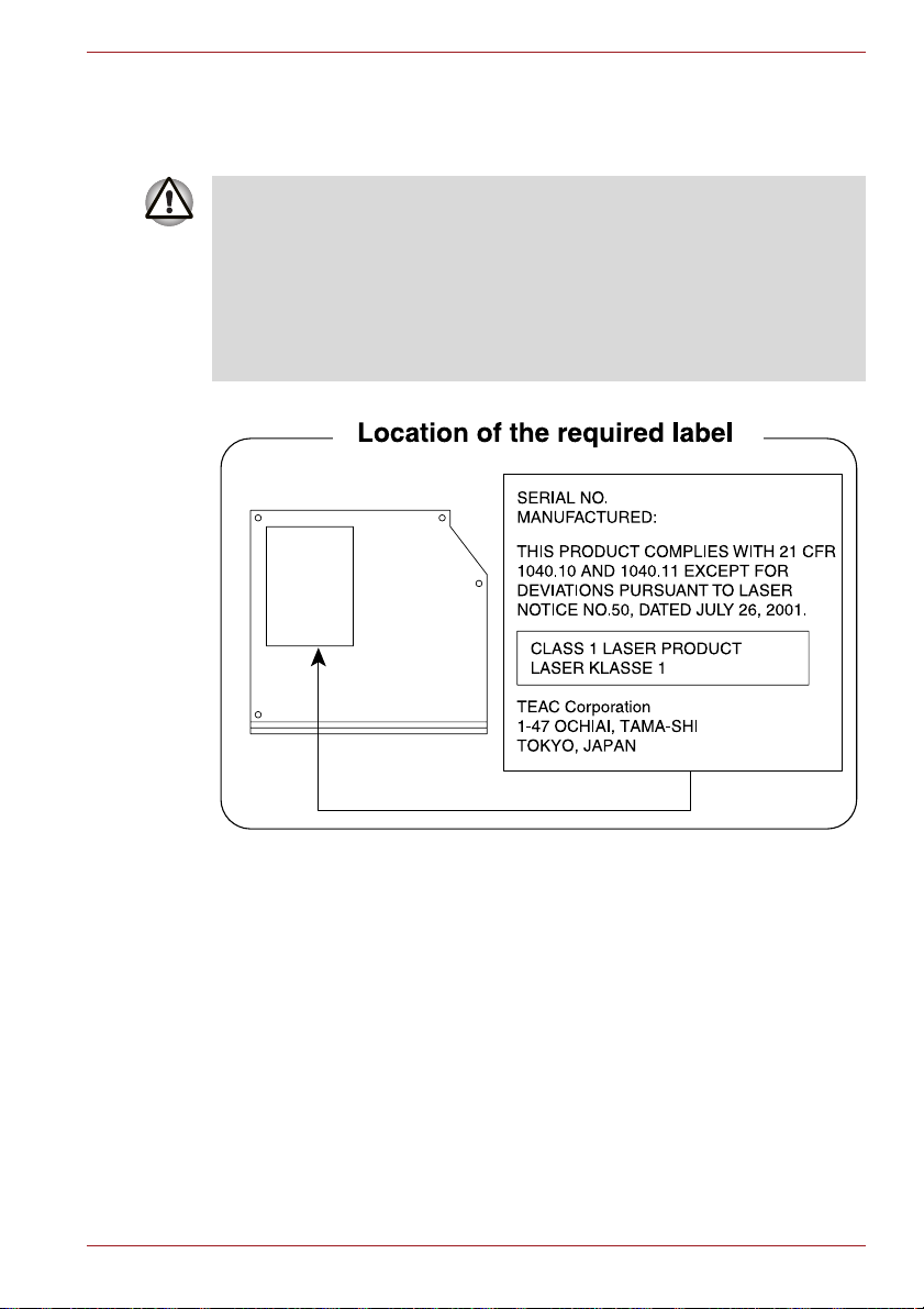
TEAC
DVD-ROM & CD-R/RW drive DW-224S
■ The DVD-ROM & CD-R/RW drive model employs a laser system. To
ensure proper use of this product, please read this instruction manual
carefully and retain for future reference. Should the unit ever require
maintenance, contact an authorized service location.
■ Use of controls, adjustments or the performance of procedures other
than those specified may result in hazardous radiation exposure.
■ To prevent direct exposure to the laser beam, do not try to open the
enclosure.
User’s Manual xviii

TECRA A10/S10/P10/M10/Satellite S300L/Satellite Pro S300/S300L
TEAC
DVD Super Multi with Double Layer Recording DV-W28S
■ The DVD Super Multi drive model employs a laser system. To ensure
proper use of this product, please read this instruction manual carefully
and retain for future reference. Should the unit ever require
maintenance, contact an authorized service location.
■ Use of controls, adjustments or the performance of procedures other
than those specified may result in hazardous radiation exposure.
■ To prevent direct exposure to the laser beam, do not try to open the
enclosure.
User’s Manual xix
TECRA A10/S10/P10/M10/Satellite S300L/Satellite Pro S300/S300L
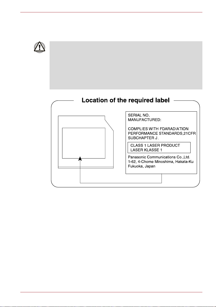
Panasonic Communications
DVD Super Multi with Double Layer Recording UJ870/UJ880
■ The DVD Super Multi drive model employs a laser system. To ensure
proper use of this product, please read this instruction manual carefully
and retain for future reference. Should the unit ever require
maintenance, contact an authorized service location.
■ Use of controls, adjustments or the performance of procedures other
than those specified may result in hazardous radiation exposure.
■ To prevent direct exposure to the laser beam, do not try to open the
enclosure.
User’s Manual xx
TECRA A10/S10/P10/M10/Satellite S300L/Satellite Pro S300/S300L
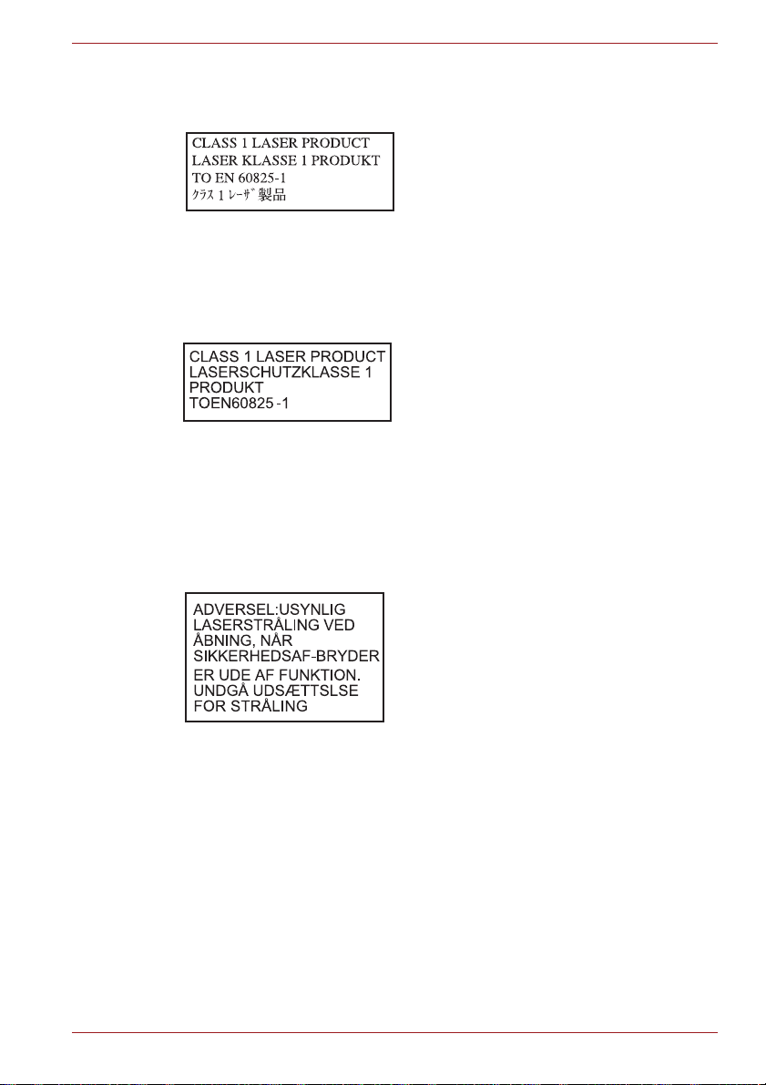
International precautions
CAUTION: This appliance contains a
laser system and is classified as a
“CLASS 1 LASER PRODUCT.” To use
this model properly, read the instruction
manual carefully and keep this manual
for your future reference. In case of any
trouble with this model, please contact
your nearest “AUTHORIZED service
station.” To prevent direct exposure to the
laser beam, do not try to open the
enclosure.
VORSICHT: Dieses Gerät enthält ein
Laser-System und ist als
“LASERSCHUTZKLASSE 1 PRODUKT”
klassifiziert. Für den richtigen Gebrauch
dieses Modells lesen Sie bitte die
Bedienungsanleitung sorgfältig durch
und bewahren diese bitte als Referenz
auf. Falls Probleme mit diesem Modell
auftreten, benachrichtigen Sie bitte die
nächste “autorisierte Service-Vertretung”.
Um einen direkten Kontakt mit dem
Laserstrahl zu vermeiden darf das Gerät
nicht geöffnet werden.
User’s Manual xxi
ADVARSEL: Denne mærking er anbragt
udvendigt på apparatet og indikerer, at
apparatet arbejder med laserstråler af
klasse 1, hviket betyder, at der anvendes
laserstrlier af svageste klasse, og at man
ikke på apparatets yderside kan bilve
udsat for utilladellg kraftig stråling.
APPARATET BOR KUN ÅBNES AF
FAGFOLK MED SÆRLIGT KENDSKAB
TIL APPARATER MED
LASERSTRÅLER!
Indvendigt i apparatet er anbragt den her
gengivne advarselsmækning, som
advarer imod at foretage sådanne
indgreb i apparatet, at man kan komme til
at udsatte sig for laserstråling.

TECRA A10/S10/P10/M10/Satellite S300L/Satellite Pro S300/S300L
OBS! Apparaten innehåller
laserkomponent som avger laserstråining
överstigande gränsen för laserklass 1.
VAROITUS. Suojakoteloa si saa avata.
Laite sisältää laserdiodin, joka lähetää
näkymätöntä silmilie vaarallista
lasersäteilyä.
CAUTION: USE OF CONTROLS OR
ADJUSTMENTS OR PERFORMANCE
OF PROCEDURES OTHER THAN
THOSE SPECIFIED IN THE OWNER’S
MANUAL MAY RESULT IN
HAZARDOUS RADIATION EXPOSURE.
VORSICHT: DIE VERWENDUNG VON
ANDEREN STEURUNGEN ODER
EINSTELLUNGEN ODER DAS
DURCHFÜHREN VON ANDEREN
VORGÄNGEN ALS IN DER
BEDIENUNGSANLEITUNG
BESCHRIEBEN KÖNNEN
GEFÄHRLICHE
STRAHLENEXPOSITIONEN ZUR
FOLGE HABEN.
User’s Manual xxii

Preface
Congratulations on your purchase of the TECRA
A10/S10/P10/M10/Satellite S300L/Satellite Pro S300/S300L Series
computer. This powerful notebook computer provides excellent expansion
capability, includes multimedia functionality, and is designed to provide
years of reliable, high-performance computing.
This manual tells how to set up and begin using your TECRA
A10/S10/P10/M10/Satellite S300L/Satellite Pro S300/S300L computer. It
also provides detailed information on configuring your computer, basic
operations and care, using optional devices and troubleshooting.
If you are a new user of computers or if you’re new to portable computing,
first read over the Chapter 1, Getting Started and Chapter 3, Hardware,
Utilities and Options chapters to familiarize yourself with the computer’s
features, components and accessory devices. Then read Chapter 1,
Getting Started for step-by-step instructions on setting up your computer.
If you are an experienced computer user, please continue reading the
preface to learn how this manual is organized, then become acquainted
with this manual by browsing through its pages. Be sure to read the Special
features section in Chapter 3, Hardware, Utilities and Options to learn
about features that are uncommon or unique to this computer, as well as
the section on Chapter 7, HW Setup, to understand how to setup and
configure these features.
Read Chapter 3, Hardware, Utilities and Options if connecting optional
products or external devices.
Conventions
This manual uses the following formats to describe, identify, and highlight
terms and operating procedures.
Abbreviations
On first appearance, and whenever necessary for clarity, abbreviations are
enclosed in parentheses following their definition. For example: Read Only
Memory (ROM). Acronyms are also defined in the Glossary.
User’s Manual xxiii

TECRA A10/S10/P10/M10/Satellite S300L/Satellite Pro S300/S300L
Icons
Icons identify ports, dials, and other parts of your computer. The indicator
panel also uses icons to identify the components it is providing information
on.
Keys
The keyboard keys are used in the text to describe many computer
operations. A distinctive typeface identifies the key top symbols as they
appear on the keyboard. For example, ENTER identifies the ENTER key.
Key operation
Some operations require you to simultaneously use two or more keys. We
identify such operations by the key top symbols separated by a plus sign
(+). For example, CTRL + C means you must hold down CTRL and at the
same time press C. If three keys are used, hold down the first two and at
the same time press the third.
ABC
When procedures require an action such as
clicking an icon or entering text, the icon's name
or the text you are to type in is represented in the
typeface you see to the left.
Display
S ABC
Names of windows or icons or text generated by
the computer that appear on its display screen
are presented in the type face you see to the left.
Messages
Messages are used in this manual to bring important information to your
attention. Each type of message is identified as shown below.
Pay attention! A caution informs you that improper use of equipment or
failure to follow instructions may cause data loss or damage your
equipment.
Please read. A note is a hint or advice that helps you make best use of
your equipment.
Indicates a potentially hazardous situation, which could result in death or
serious injury, if you do not follow instructions.
User’s Manual xxiv

TECRA A10/S10/P10/M10/Satellite S300L/Satellite Pro S300/S300L
Terminology
This term is defined in this document as follows:
Start The word "Start" refers to the " " button in
Windows 7.
HDD or Hard disk
drive
Some models are equipped with a "Solid State
Drive (SSD)" instead of a hard disk drive.
In this manual, the word "HDD" or "Hard disk
drive" also refers to the SSD unless otherwise
stated.
User’s Manual xxv

General Precautions
TOSHIBA computers are designed to optimize safety, minimize strain and
withstand the rigors of portability. However, certain precautions should be
observed to further reduce the risk of personal injury or damage to the
computer.
Be certain to read the general precautions below and to note the cautions
included in the text of the manual.
Provide adequate ventilation
■ Always make sure your computer and AC adaptor have adequate
ventilation and are protected from overheating when the power is
turned on or when an AC adaptor is connected to a power outlet (even if
your computer is in Sleep Mode). In this condition, observe the
following:
■ Never cover your computer or AC adaptor with any object.
■ Never place your computer or AC adaptor near a heat source, such
as anelectric blanket or heater.
■ Never cover or block the air vents including those located at the
base of the computer.
■ Always operate your computer on a hard flat surface. Using your
computer on a carpet or other soft material can block the vents.
■ Always provide sufficient space around the computer.
■ Overheating your computer or AC adaptor could cause system failure,
computer or AC adaptor damage or a fire, possibly resulting in serious
injury.
User’s Manual xxvi

TECRA A10/S10/P10/M10/Satellite S300L/Satellite Pro S300/S300L
Creating a computer-friendly environment
Place the computer on a flat surface that is large enough for the computer
and any other items you are using, such as a printer.
Leave enough space around the computer and other equipment to provide
adequate ventilation. Otherwise, they may overheat.
To keep your computer in prime operating condition, protect your work area
from:
■ Dust, moisture, and direct sunlight.
■ Equipment that generates a strong electromagnetic field, such as
stereo speakers (other than speakers that are connected to the
computer) or speakerphones.
■ Rapid changes in temperature or humidity and sources of temperature
change such as air conditioner vents or heaters.
■ Extreme heat, cold, or humidity.
■ Liquids and corrosive chemicals.
Stress injury
Carefully read the Instruction Manual for Safety and Comfort. It contains
information on the prevention of stress injuries to your hands and wrists
that can be caused by extensive keyboard use. Instruction Manual for
Safety and Comfort also includes information on work space design,
posture and lighting that can help reduce physical stress.
Heat injury
■ Avoid prolonged physical contact with the computer. If the computer is
used for long periods, its surface can become very warm. While the
temperature will not feel hot to the touch, if you maintain physical
contact with the computer for a long time, for example if you rest the
computer on your lap or if you keep your hands on the palm rest, your
skin might suffer a low-heat injury.
■ If the computer has been used for a long time, avoid direct contact with
the metal plate supporting the various interface ports as this can
become hot.
■ The surface of the AC adaptor can become hot when in use but this
condition does not indicate a malfunction. If you need to transport the
AC adaptor, you should disconnect it and let it cool before moving it.
■ Do not lay the AC adaptor on a material that is sensitive to heat as the
material could become damaged.
User’s Manual xxvii

TECRA A10/S10/P10/M10/Satellite S300L/Satellite Pro S300/S300L
Pressure or impact damage
Do not apply heavy pressure to the computer or subject it to any form of
strong impact as this can damage the computer's components or otherwise
cause it to malfunction.
PC Card overheating
Some PC Cards can become hot during prolonged use which may result in
errors or instability in the operation of the device in question. In addition,
you should also be careful when you remove a PC Card that has been
used for a long time.
Mobile phones
Please be aware that the use of mobile phones can interfere with the audio
system. The operation of the computer will not be impaired in any way, but
it is recommended that a minimum distance of 30cm is maintained between
the computer and a mobile phone that is in use.
Instruction Manual for Safety and Comfort
All important information on the safe and proper use of this computer is
described in the enclosed Instruction Manual for Safety and Comfort. Be
sure to read it before using the computer.
User’s Manual xxviii
Getting Started
This chapter provides an equipment checklist, and basic information to start
using your computer.
Some of the features described in this manual may not function properly if
you use an operating system that was not pre-installed by TOSHIBA.
Equipment checklist
Carefully unpack your computer, taking care to save the box and packaging
materials for future use.
Hardware
Check to make sure you have all the following items:
■ TECRA A10/S10/P10/M10/Satellite S300L/Satellite Pro S300/S300L
Portable Personal Computer
■ AC adaptor and power cord (2-pin plug or 3-pin plug)
■ Battery pack
■ Spare AccuPoint (pointing device) cap (Is included with some models)
Chapter 1
Documentation
■ TECRA A10/S10/P10/M10/Satellite S300L/Satellite Pro
S300/S300L Series User Information Guide
■ Instruction Manual for Safety and Comfort
■ End User License Agreement
If any of the items are missing or damaged, contact your dealer
immediately.
User’s Manual 1-1

Software
The following Windows® operating system and utility software are preinstalled.
■ Windows 7
■ TOSHIBA Value Added Package
■ TOSHIBA Recovery Media Creator
■ TOSHIBA DVD Player
■ TOSHIBA SD Memory Utilities
■ TOSHIBA SD Memory Boot Utility
■ TOSHIBA Assist
■ TOSHIBA ConfigFree™
■ TOSHIBA HDD Protection
■ TOSHIBA Disc Creator
■ TOSHIBA Face Recognition (Is preinstalled in some models)
■ TOSHIBA eco Utility
■ Fingerprint Utility
■ Windows Mobility Center
■ Online Manual
■ TECRA A10/S10/P10/M10/Satellite S300L/Satellite Pro
S300/S300L User's Manual (This manual)
Getting Started
User’s Manual 1-2

Getting Started
■ All users should be sure to read the section Starting up for the first time.
■ Be sure to read the enclosed Instruction Manual for Safety and Comfort
for information on the safe and proper use of this computer. It is
intended to help you be more comfortable and productive while using a
notebook computer. By following the recommendations in it you may
reduce your chance of developing a painful or disabling injury to your
hand, arms, shoulders or neck.
This section provides basic information to start using your computer. It
covers the following topics:
■ Connecting the AC adaptor
■ Opening the display
■ Turning on the power
■ Starting up for the first time
■ Turning off the power
■ Restarting the computer
■ System Recovery Options
■ Creating Recovery Media
■ Restoring the pre-installed software from the Recovery hard disk drive
■ Restoring the pre-installed software from your created Recovery Media
Getting Started
■ Use a virus-check program and make sure it is updated regularly.
■ Never format storage media without checking its content - formatting
destroys all stored data.
■ It is a good idea to periodically back up the internal hard disk drive or
other main storage device to external media. General storage media is
not durable or stable over long periods of time and under certain
conditions may result in data loss.
■ Before you install a device or application, save any data in memory to
the hard disk drive or other storage media. Failure to do so may result
in the loss of data.
User’s Manual 1-3

Connecting the AC adaptor
Attach the AC adaptor when you need to charge the battery or you want to
operate from AC power. It is also the fastest way to get started, because
the battery pack will need to be charged before you can operate from
battery power.
The AC adaptor can be connected to any power source supplying from 100
to 240 volts and 50 or 60 hertz. For details on using the AC adaptor to
charge the battery pack, refer to Chapter 6, Power and Power-Up Modes.
■ Always use the TOSHIBA AC adaptor that was included with your
computer, or use AC adaptors specified by TOSHIBA to avoid any risk
of fire or other damage to the computer. Use of an incompatible AC
adaptor could cause fire or damage to the computer possibly resulting
in serious injury. TOSHIBA assumes no liability for any damage caused
by use of an incompatible adaptor.
■ Never plug the AC adaptor into a power source that does not
correspond to both the voltage and the frequency specified on the
regulatory label of the unit. Failure to do so could result in a fire or
electric shock, possibly resulting in serious injury.
■ Always use or purchase power cables that comply with the legal
voltage and frequency specifications and requirements in the country of
use. Failure to do so could result in a fire or electric shock, possibly
resulting in serious injury.
■ The supplied power cord conforms to safety rules and regulations in
the region the product is bought and should not be used outside this
region. For use in other regions, please buy power cords that conform
to safety rules and regulations in the particular region.
■ Do not use a 3-pin to 2-pin conversion plug.
■ When you connect the AC adaptor to the computer, always follow the
steps in the exact order as described in the User’s Manual. Connecting
the power cable to a live electrical outlet should be the last step
otherwise the adaptor DC output plug could hold an electrical charge
and cause an electrical shock or minor bodily injury when touched. As
a general safety precaution, avoid touching any metal parts.
■ Never place your computer or AC adaptor on a wooden surface,
furniture, or any other surface that could be marred by exposure to heat
since the computer base and AC adaptor's surface increase in
temperature during normal use.
■ Always place your computer or AC adaptor on a flat and hard surface
that is resistant to heat damage.
Refer to the enclosed Instruction Manual for Safety and Comfort for
detailed precautions and handling instructions.
Getting Started
User’s Manual 1-4

Getting Started
1. Connect the power cord to the AC adaptor.
Figure 1-1 Connecting the power cord to the AC adaptor (2-pin plug)
Figure 1-2 Connecting the power cord to the AC adaptor (3-pin plug)
Either a 2-pin or 3-pin adaptor/cord will be included with the computer
depending on the model.
2. Connect the AC adaptor’s DC output plug to the DC IN 15V jack on the
back of the computer.
DC IN 15V jack
DC output plug
Figure 1-3 Connecting the DC output plug to the computer
3. Plug the power cord into a live wall outlet - the Battery and DC IN
indicators on the front of the computer should glow.
User’s Manual 1-5

Opening the display
The display panel can be opened to a wide range of angles for optimal
viewing.
While holding down the palm rest with one hand so that the main body of
the computer is not raised, slowly lift the display panel - this will allow the
angle of the display panel to be adjusted to provide optimum clarity.
Display panel
Figure 1-4 Opening the display panel
Use reasonable care when opening and closing the display panel. Opening
it vigorously or slamming it shut could damage the computer.
Getting Started
■ Be careful not to open the display panel too far as this could put stress
on the display panel’s hinges and cause damage.
■ Do not press or push on the display panel.
■ Do not lift the computer by the display panel.
■ Do not close the display panel with pens or any other objects left in
between the display panel and the keyboard.
■ When opening or closing the display panel, place one hand on the
palm rest to hold the computer in place and use the other hand to
slowly open or close the display panel (Do not use excessive force
when opening or closing the display panel).
User’s Manual 1-6

Turning on the power
This section describes how to turn on the power - the Power indicator will
then indicate the status. Please refer to the Monitoring of power condition
section in Chapter 6, Power and Power-Up Modes for more information.
■ After you turn on the power for the first time, do not turn it off until you
have set up the operating system. Please refer to the section Starting
up for the first time for more information.
■ Volume cannot be adjusted during Windows Setup.
1. Open the display panel.
2. Press and hold the computer's power button for two or three seconds.
Power button
Getting Started
Figure 1-5 Turning on the power
Starting up for the first time
The Windows 7 Startup Screen will be the first screen displayed when you
turn on the power. Follow the on-screen instructions on each screen in
order to properly install the operating system.
When it is displayed, be sure to read the Software License Terms
carefully.
Turning off the power
The power can be turned off in one of three modes, either Shut Down
Mode, Hibernation Mode or Sleep Mode.
Shut Down Mode
When you turn off the power in Shut Down Mode no data will be saved and
the computer will boot to the operating system's main screen the next time
it is turned on.
1. If you have entered data, either save it to the hard disk drive or to other
storage media.
2. Make sure all disk/disc activity has stopped before removing the
CD/DVD or floppy diskette.
User’s Manual 1-7

Getting Started
■ Make sure the Hard Disk Drive/Optical Disc Drive indicators are off.
If you turn off the power while a disk (disc) is being accessed, you may
lose data or damage the disk.
■ Never turn off the power while an application is running. Doing so could
cause loss of data.
■ Never turn off the power, disconnect an external storage device or
remove storage media during data read/write. Doing so can cause data
loss.
3. Click Start.
4. Click the Shut down button ( ).
5. Turn off any peripheral devices connected to your computer.
Do not turn the computer or peripheral devices back on immediately - wait
a short period to avoid any potential damage.
Sleep Mode
If you have to interrupt your work, you are able to turn off the power without
exiting from your software by placing the computer into Sleep Mode. In this
mode data is maintained in the computer's main memory so that when you
turn on the power again, you can continue working right where you left off.
When you have to turn off your computer aboard an aircraft or in places
where electronic devices are regulated or controlled, always completely
shut down the computer. This includes turning off any wireless
communication switches or devices, and canceling settings that reactivate
the computer automatically, such as a timer recording function. Failure to
completely shut down the computer in this way could allow the operating
system to reactivate and run pre-programmed tasks or preserve unsaved
data, which could interfere with aviation or other systems, possibly causing
serious injury.
■ Before entering Sleep Mode, be sure to save your data.
■ Do not install or remove a memory module while the computer is in
Sleep Mode. The computer or the memory module could be damaged.
■ Do not remove the battery pack while the computer is in Sleep Mode
(unless the computer is connected to an AC power source). Data in
memory could be lost.
User’s Manual 1-8

Getting Started
■ When the AC adaptor is connected, the computer will go into Sleep
Mode according to the settings in the Power Options (to access it, Start
-> Control Panel -> System and Security -> Power Options).
■ To restore the operation of the computer from Sleep Mode, press and
hold the power button or any key on the keyboard for a short amount of
time. Please note that keyboard keys can only be used if the Wake-up
on Keyboard option is enabled within the HW Setup utility.
■ If the computer enters Sleep Mode while a network application is
active, the application might not be restored when the computer is next
turned on and the system returns from Sleep Mode.
■ To prevent the computer from automatically entering Sleep Mode,
disable Sleep Mode within the Power Options (to access it, Start ->
Control Panel -> System and Security -> Power Options).
■ To use the Hybrid Sleep function, configure it in the Power Options.
Benefits of Sleep Mode
The Sleep Mode feature provides the following benefits:
■ Restores the previous working environment more rapidly than does the
Hibernation Mode feature.
■ Saves power by shutting down the system when the computer receives
no input or hardware access for the time period set by the System
Sleep Mode feature.
■ Allows the use of the panel power off feature.
Executing Sleep Mode
You can also enable Sleep Mode by pressing FN + F3 - please refer to
Chapter 5, The Keyboard, for further details.
You can enter Sleep Mode in one of three ways:
■ Click Start, point to the arrow icon ( ) and then select
Sleep from the menu.
■ Close the display panel. Please note that this feature must be enabled
within the Power Options (to access it, click Start -> Control Panel ->
System and Security -> Power Options).
■ Press the power button. Please note that this feature must be enabled
within the Power Options (to access it, click Start -> Control Panel ->
System and Security -> Power Options).
When you turn the power back on, you can continue where you left when
you shut down the computer.
■ When the computer is in Sleep Mode, the power indicator will blink
orange.
■ If you are operating the computer on battery power, you can lengthen
the overall operating time by turning it off into Hibernation Mode - Sleep
Mode will consume more power while the computer is off.
User’s Manual 1-9

Getting Started
Sleep Mode limitations
Sleep Mode will not function under the following conditions:
■ Power is turned back on immediately after shutting down.
■ Memory circuits are exposed to static electricity or electrical noise.
Hibernation Mode
The Hibernation Mode feature saves the contents of memory to the hard
disk drive when the computer is turned off so that, the next time it is turned
on, the previous state is restored. Please note that the Hibernation Mode
feature does not save the status of any peripheral devices connected to the
computer.
■ Save your data. While entering Hibernation Mode, the computer saves
the contents of memory to the hard disk drive. However, for safety
sake, it is best to save your data manually.
■ Data will be lost if you remove the battery or disconnect the AC adaptor
before the save is completed. Wait for the Hard Disk Drive indicator to
go out.
■ Do not install or remove a memory module while the computer is in
Hibernation Mode. Data will be lost.
Benefits of Hibernation Mode
The Hibernation Mode feature provides the following benefits:
■ Saves data to the hard disk drive when the computer automatically
shuts down because of a low battery condition.
■ You can return to your previous working environment immediately when
you turn on the computer.
■ Saves power by shutting down the system when the computer receives
no input or hardware access for the time period set by the System
Hibernate feature.
■ Allows the use of the panel power off feature.
Starting Hibernation Mode
You can also enable Hibernation Mode by pressing FN + F4 - please refer
to Chapter 5, The Keyboard, for further details.
To enter Hibernation Mode, follow the steps below.
1. Click Start.
2. Point to the arrow icon ( ) and then select Hibernate
from the menu.
User’s Manual 1-10

Automatic Hibernation Mode
The computer can be configured to enter Hibernation Mode automatically
when you press the power button or close the lid. In order to define these
settings, you can follow the steps as described below:
1. Click Start and click the Control Panel.
2. Click System and Security and click Power Options.
3. Click Choose what the power button does or Choose what closing
the lid does.
4. Enable the desired Hibernation Mode settings for When I press the
power button and When I close the lid.
5. Click the Save changes button.
Data save in Hibernation Mode
When you turn off the power in Hibernation Mode, the computer will take a
moment to save the current data in memory to the hard disk drive. During
this time, the Hard Disk Drive indicator will glow.
After you turn off the computer, and the content of memory has been saved
to the hard disk drive, turn off the power to any peripheral devices.
Do not turn the computer or devices back on immediately. Wait a moment
to let all capacitors fully discharge.
Restarting the computer
Certain conditions require that you reset the computer, for example if:
■ You change certain computer settings.
■ An error occurs and the computer does not respond to your keyboard
commands.
If you need to restart the computer, there are three ways this can be
achieved:
■ Click Start, point to the arrow icon ( ) and then select
Restart from the menu.
■ Press CTRL, ALT and DEL simultaneously (once) to display the menu
window, then select Restart from the Shut down options.
■ Press the power button and hold it down for five seconds. Once the
computer has turned itself off, wait between ten and fifteen seconds
before turning the power on again by pressing the power button.
Getting Started
User’s Manual 1-11

System Recovery Options
There is a hidden partition allocated on the hard disk drive for the System
Recovery Options.
This partition stores files which can be used to repair the system in the
event of a problem.
The System Recovery Options feature will be unusable if this partition is
deleted.
System Recovery Options
The System Recovery Options feature is installed on the hard disk when
shipped from the factory. The System Recovery Options menu includes
tools to repair startup problems, run diagnostics or restore the system.
See the Windows Help and Support content for more information about
Startup Repair.
The System Recovery Options can also be run manually to repair
problems.
The procedure is as follows. Follow the instructions shown on the onscreen menu.
1. Turn off the computer.
2. While holding the F8 key, turn on the computer.
3. The Advanced Boot Options menu will be displayed.
Use the arrow keys to select Repair Your Computer and press
ENTER.
4. Follow the on-screen instructions.
Getting Started
Check your Windows® manual for more information on backing up your
system (including the system image backup feature).
User’s Manual 1-12

System Recovery
This section describes the creation of Recovery Media and their use.
Creating Recovery Media
This section describes how to create Recovery Media.
■ Be sure to connect the AC adaptor when you create Recovery Media.
■ Be sure to close all other software programs except the Recovery
Media Creator.
■ Do not run software such as screen savers which can put a heavy load
on the CPU.
■ Operate the computer at full power.
■ Do not use power-saving features.
■ Do not write to the media when the virus check software is running.
Wait for it to finish, then disable virus detection programs including any
software that checks files automatically in the background.
■ Do not use utilities, including those intended to enhance hard disk drive
access speed. They may cause unstable operation and damage data.
■ Do not shut down/log off or Sleep/Hibernate while writing or rewriting
the media.
■ Set the computer on a level surface and avoid places subjected to
vibrations such as airplanes, trains, or cars.
■ Do not use on an unstable surface such as a stand.
Getting Started
A recovery image of the software on your computer is stored on the hard
disk drive, and can be copied to either CD, DVD or USB Flash Memory by
using the following steps:
1. Select either blank CD, DVD or USB Flash Memory.
The application will allow you to choose from a variety of different media
onto which the recovery image can be copied including CD-R, CD-RW,
DVD-R, DVD-R DL, DVD-RW, DVD+R, DVD+R DL, DVD+RW and USB
Flash Memory.
■ Please note that some of the above media may not be compatible with
the optical disc drive installed into your computer. You should therefore
verify the optical disc drive supports the blank media you have chosen
before proceeding.
■ USB Flash Memory will be formatted and all the data in the USB Flash
Memory will be lost when proceeding.
2. Turn on your computer and allow it to load the Windows 7 operating
system from the hard disk drive as normal.
3. Insert the media into the computer.
■ Insert the first blank disc into the optical disc drive tray, or
Insert the USB Flash Memory into one available USB port
User’s Manual 1-13

Getting Started
4. Double click the Recovery Media Creator icon on the Windows 7
desktop, or select the application from Start Menu.
5. After Recovery Media Creator starts, select the type of media and the
title you wish to copy, and then click the Create button.
Restoring the pre-installed software from the Recovery hard disk
drive
A portion of the total hard disk drive space is configured as a hidden
recovery partition. This partition stores files which can be used to restore
pre-installed software in the event of a problem.
If you subsequently set up your hard disk drive again, do not change,
delete or add partitions in a manner other than specified in the manual,
otherwise you may find that space for the required software is not available.
In addition, if you use a third-party partitioning program to reconfigure the
partitions on your hard disk drive, you may find that it becomes impossible
to setup your computer.
When the sound mute feature has been activated by pressing the FN +
ESC key, be sure to disable this to allow sounds to be heard before starting
the restore process. Please refer to Chapter 5, The Keyboard, for further
details.
You can not use System Recovery Options if restoring the pre-installed
software without System Recovery Options.
When you reinstall the Windows operating system, the hard disk will be
reformatted and all data will be lost.
1. Turn off your computer.
2. While holding down 0 (zero) key on the keyboard, turn on your
computer.
3. A menu will be displayed from which you should follow the on-screen
instructions.
User’s Manual 1-14
Getting Started
Restoring the pre-installed software from your created Recovery
Media
If the pre-installed files are damaged, you are able to either use the
Recovery Media you have created or the hard disk drive recovery process
to restore the computer to the state it was in when you originally received it.
To perform this restoration, follow the steps below:
When the sound mute feature has been activated by pressing the FN +
ESC key, be sure to disable this to allow sounds to be heard before starting
the restore process. Please refer to Chapter 5, The Keyboard, for further
details.
You can not use System Recovery Options if restoring the pre-installed
software without System Recovery Options.
When you reinstall the Windows operating system, the hard disk will be
reformatted and all data will be lost.
1. Load the Recovery Media into the computer and turn off the computer's
power.
2. While holding down F12 key on the keyboard, turn on your computer -
when the TOSHIBA logo screen appears, release the F12 key.
3. Use the left and right cursors key to select the appropriate icon (CD-
ROM or USB icon) of your actual recovery media from the menu.
Please refer to the Boot Priority section in Chapter 7, HW Setup for
further information.
4. A menu will be displayed from which you should follow the on-screen
instructions.
When drivers/utilities are installed, you can setup the respective
drivers/utilities from the following place. To open the setup files, Click Start
-> All Programs -> TOSHIBA -> Applications and Drivers.
User’s Manual 1-15
The Grand Tour
This chapter identifies the various components of the computer - it is
recommended that you become familiar with each before you operate the
computer.
Legal Footnote (Non-applicable Icons)*1
For more information regarding Non-applicable Icons, please refer to the
Legal Footnotes section in Appendix H or click the *1 above.
Please handle your computer carefully to avoid scratching or damaging the
surface.
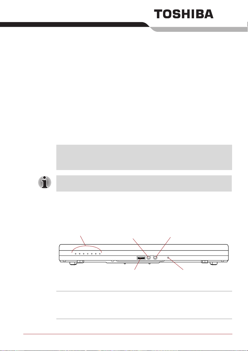
Front with the display closed
The following figure shows the computer’s front with its display panel in the
closed position.
System indicators
Headphone jack
Chapter 2
Microphone jack
Volume control dial
Figure 2-1 Front of the computer with display panel closed
System indicators These LED indicators allow you to monitor the
status of various computer functions and are
described in more detail within the System
indicators section.
User’s Manual 2-1
Microphone

The Grand Tour
Volume control dial Use this dial to adjust the volume of the internal
stereo speaker and optional external stereo
headphones (if connected).
Move the Volume control dial to the right to
increase the volume and to the left to decrease
the volume.
Headphone jack A 3.5 mm mini headphone jack enables
connection of stereo headphones.
Microphone jack A 3.5 mm mini microphone jack enables
connection of a three-conductor mini jack for
monaural microphone input.
Left side
Microphone A built-in microphone allows you to import and
record sounds for your application - please refer
to the Sound System section in Chapter 4,
Operating Basics for more information. Some
models are equipped with a Microphone.
The following figure shows the computer’s left side.
Serial port
Wireless
communication switch
Cooling vents
Figure 2-2 The left side of the computer
eSATA/USB
combo port
PC Card eject
button
Bridge media
slot
ExpressCard slot
or PC Card slot
i.LINK (IEEE1394)
port
Serial port Use this 9-pin port to connect serial devices such
as an external modem, serial mouse or serial
printer.
Some models are equipped with a serial port.
Cooling vents The cooling vents help keep the processor from
overheating.
User’s Manual 2-2

The Grand Tour
Do not block the cooling vents. Keep foreign metal objects, such as
screws, staples and paper clips, out of the cooling vents. Foreign metal
objects can create a short circuit, which can cause damage and fire,
possibly resulting in serious injury.
Wireless
communication
switch
Slide this switch to the right to turn off Wireless
LAN, Bluetooth
™
and Wireless WAN functions.
Slide it to the left to turn on the functions.
Only some models are equipped with Bluetooth,
Wireless LAN and Wireless WAN functions.
■ Do not use the Wireless LAN (Wi-Fi®) or Bluetooth functionalities near
a microwave oven or in areas subject to radio interference or magnetic
fields. Interference from a microwave oven or other source can disrupt
Wi-Fi or Bluetooth operation.
■ Turn all wireless functionalities off when near a person who may have a
cardiac pacemaker implant or other medical electric device. Radio
waves may affect pacemaker or medical device operation, possibly
resulting in serious injury. Follow the instruction of your medical device
when using any wireless functionality.
■ Always turn off wireless functionality if the computer is near automatic
control equipment or appliances such as automatic doors or fire
detectors. Radio waves can cause malfunction of such equipment,
possibly resulting in serious injury.
eSATA/USB combo
port
One eSATA/USB combo port, which complies to
the USB 2.0 standard, is provided on the left
hand side of the computer. The ports with the
icon ( ) has USB Sleep and Charge. This port
has eSATA (External Serial ATA) function. Some
models are equipped with a eSATA/USB combo
port.
Keep foreign metal objects, such as screws, staples and paper clips, out of
the eSATA/USB combo port. Foreign metal objects can create a short
circuit, which can cause damage and fire, possibly resulting in serious
injury.
Please note that it is not possible to confirm the operation of all functions of
all USB devices that are available. In view of this it may be noted that some
functions associated with a specific device might not operate properly.
User’s Manual 2-3

The Grand Tour
Bridge media slot This slot lets you insert an SD™/SDHC™
memory card, miniSD™/microSD™ Card,
Memory Stick
®
(PRO™/PRO Duo™), xD-Picture
Card™ and MultiMediaCard™. Refer to the
Optional devices section in Chapter 3, Hardware,
Utilities and Options.
Keep foreign metal objects, such as screws, staples and paper clips, out of
the Bridge media slot. Foreign metal objects can create a short circuit,
which can cause damage and fire, possibly resulting in serious injury.
ExpressCard slot This slot allows you to install a single
ExpressCard device.
PC Card slot This slot can accommodate a single Type II, 16-
bit or 32-bit (CardBus) PC Card device.
PC Card eject button This button is used in order to remove a PC Card
from within the computer.
Keep foreign metal objects, such as screws, staples and paper clips, out of
the PC Card slot. Foreign metal objects can create a short circuit, which
can cause damage and fire, possibly resulting in serious injury.
i.LINK (IEEE1394)
port
This port allows you to connect an external
device, such as a digital video camera for highspeed data transfer.
Some models are equipped with a i.LINK
(IEEE1394) port.
Right side
The following figure shows the computer’s right side.
Smart Card slot
Optical disc drive
Figure 2-3 The right side of the computer
User’s Manual 2-4
Universal Serial Bus
(USB 2.0) ports
Modem jack
Security lock slot

The Grand Tour
Smart Card slot This slot can accommodate a single Smart Card
device. Some models are equipped with a Smart
Card slot.
Keep foreign metal objects, such as screws, staples and paper clips, out of
the Smart Card slot. Foreign metal objects can create a short circuit, which
can cause damage and fire, possibly resulting in serious injury.
Optical disc drive The computer is configured with a DVD-ROM,
DVD-ROM&CD-R/RW or DVD Super Multi drive.
Universal Serial Bus
(USB 2.0) ports
Three Universal Serial Bus ports, which comply
to the USB 2.0 standard, are provided on the
right hand side of the computer.
Keep foreign metal objects, such as screws, staples and paper clips, out of
the USB connectors. Foreign metal objects can create a short circuit,
which can cause damage and fire, possibly resulting in serious injury.
Please note that it is not possible to confirm the operation of all functions of
all USB devices that are available. In view of this it may be noted that some
functions associated with a specific device might not operate properly.
Modem jack The modem jack lets you use a modular cable to
connect the modem directly to a telephone line.
Some models are equipped with a modem jack.
■ Connection to any communication line other than an analog phone line
could cause a PC system failure.
■ Connect the built-in modem only to ordinary analog phone lines.
■ Never connect the built-in modem to a digital line (ISDN).
■ Never connect the built-in modem to the digital connector on a
public telephone or to a digital private branch exchange (PBX).
■ Never connect the built-in modem to a key telephone system for
residences or offices.
■ Avoid using your computer modem with the telephone cable connected
during an electrical storm. There may be a remote risk of electric shock
from lightning.
Security lock slot A security cable can be attached to this slot and
then connected to a desk or other large object in
order to deter theft of the computer.
User’s Manual 2-5

Back
The following figure shows the computer’s back.
LAN active indicator
(orange)
Link indicator
(green)
The Grand Tour
DC IN 15V jack
LAN jack
External monitor port
Figure 2-4 The back of the computer
LAN jack This jack lets you connect to a LAN. The adaptor
has built-in support for Ethernet LAN (10
megabits per second, 10BASE-T), Fast Ethernet
LAN (100 megabits per second, 100BASE-TX).
Some models are equipped with a Gigabit
Ethernet LAN (1000 megabits per second,
1000BASE-T). Refer to Chapter 4, Operating
Basics, for details.
■ Do not connect any cable other than a LAN cable to the LAN jack. It
could cause damage or malfunction.
■ Do not connect the LAN cable to a power supply. It could cause
damage or malfunction.
Link indicator
(green)
This indicator glows green when the computer is
connected to a LAN and the LAN is functioning
properly.
LAN active indicator
(orange)
External monitor
port
This indicator glows orange when data is being
exchanged between the computer and the LAN.
This port provides 15-pin, analog VGA port.
This port allows you to connect an external
monitor to the computer.
DC IN 15V jack The AC adaptor connects to this jack in order to
power the computer and charge its internal
batteries. Please note that you should only use
the model of AC adaptor supplied with the
computer at the time of purchase - using the
wrong AC adaptor can cause damage to the
computer.
User’s Manual 2-6

Underside
The following figure shows the underside of the computer. You should
ensure that the display is closed before the computer is turned over to
avoid causing any damage.
The Grand Tour
Battery lock
Notch
Memory module slot
Figure 2-5 The underside of the computer
Battery pack
Docking port
Battery release
latch
Notch
Notches Notches on the computer engage hooks on the
TOSHIBA Express Port Replicator to ensure a
secure connection.
Docking port This port enables connection of an optional
TOSHIBA Express Port Replicator described in
Chapter 3, Hardware, Utilities and Options.
Some models are equipped with a Docking port.
■ Only the TOSHIBA Express Port Replicator can be used with this
computer. Do not attempt to use any other Port Replicator.
■ Keep foreign objects out of the docking port. A pin or similar object can
damage the computer's circuitry.
■ Do not use the computer's External monitor port, when connecting the
TOSHIBA Express Port Replicator to the computer.
User’s Manual 2-7

The Grand Tour
Memory module slot The memory module slot allows for the
installation, replacement and removal of
additional memory module.
Refer to the Additional memory module section in
Chapter 3, Hardware, Utilities and Options.
Battery release latch Slide and hold this latch into its 'Unlock' position
in order to release the battery pack for removal.
For more detailed information on removing the
battery pack please refer to Chapter 6, Power
and Power-Up Modes.
Battery pack The battery pack provides power to the computer
when the AC adaptor is not connected. For more
detailed information on the use and operation of
the battery pack please refer to Chapter 6, Power
and Power-Up Modes.
Battery lock Slide the battery lock to release the battery pack
ready for removal.
User’s Manual 2-8

Front with the display open
This section shows the computer with the display panel open. In order to
open the display, lift the display panel up and position it at a comfortable
viewing angle for you.
Wireless LAN antenna (Not shown)
Display
screen
LCD Sensor
switch
(Not shown)
Display hinge
Stereo speaker
(Left)
Wireless WAN antennas
(Not shown)
Wireless LAN antenna
(Not shown)
Web Camera
Web Camera LED
Display hinge
The Grand Tour
Stereo speaker
(Right)
AccuPoint
AccuPoint
control buttons
Fingerprint
Sensor
Power button
TOSHIBA Assist
button
TOSHIBA
Presentation button
Keyboard
Touch Pad
Bluetooth antenna
(Not shown)
Touch Pad
control buttons
Figure 2-6 The front of the computer with the display panel open
Display hinges The display hinges allow the display panel to be
position at a variety of easy-to-view angles.
Display screen Please be aware that, when the computer is
operating on the AC adaptor, the image
displayed on the internal screen will be
somewhat brighter than when it operates on
battery power. This difference in brightness
levels is intended to save power when operating
on batteries. For more information on the
computer's display, please refer to the Display
Controller and Video mode section in Appendix
B.
Web Camera LED
The Web Camera LED glows when the Web
Camera is operating.
User’s Manual 2-9

The Grand Tour
Web Camera Web Camera is a device that allows you to
record video or take photographs with your
computer. You can use it for video chatting or
video conferences using a communication tool
such as Windows Live Messenger. TOSHIBA
Web Camera Application will help you to add
various video effects to your video or photograph.
Enables the transmission of video and use of
video chat via the internet using specialized
applications.
Some models are equipped with a Web Camera.
Please refer to the Web Camera section in
Chapter 4, Operating Basics.
Touch Pa d The Touch Pad located in the center of the palm
rest is used to control the movement of the onscreen pointer. For more information, please
refer to the Using the Touch Pad section in
Chapter 4, Operating Basics.
Touch Pad control
buttons
The control buttons located below the Touch Pad
allow you to select menu items or manipulate text
and graphics as designated by the on-screen
pointer.
AccuPoint control
buttons
Control buttons below the keyboard let you select
menu items or manipulate text and graphics
designated by the on-screen pointer. Refer to the
Using the AccuPoint section in Chapter 4,
Operating Basics.
Some models are equipped with a AccuPoint
control buttons.
AccuPoint A pointer control device located in the center of
the keyboard is used to control the on-screen
pointer. Refer to the Using the AccuPoint section
in Chapter 4, Operating Basics.
Some models are equipped with a AccuPoint.
Keyboard The internal keyboard provides the embedded
numeric overlay keys, dedicated cursor control
overlay keys, and and Keys. The
keyboard is compatible with the IBM
®
enhanced
keyboard. Refer to Chapter 5, The Keyboard, for
details.
Stereo speakers The speakers emit sound generated by your
software as well as audio alarms, such as low
battery condition, generated by the system.
User’s Manual 2-10

The Grand Tour
Power button Press this button to turn the computer's power on
and off.
TOSHIBA Assist
button
Press this button to launch the program
automatically. When power-off, Sleep Mode and
Hibernation Mode, press this button to start the
computer and launch the program.
Some models are equipped with a TOSHIBA
Assist button.
TOSHIBA
Presentation button
The TOSHIBA Presentation button has the same
functionality as the Connect display button in the
Mobility Center.
Some models are equipped with a TOSHIBA
Presentation button.
Fingerprint Sensor This sensor enables you to enroll and recognize
a fingerprint.
For detailed information on Fingerprint Sensor,
refer to Chapter 4, Using the Fingerprint Sensor.
Some models are equipped with a Fingerprint
Sensor.
LCD Sensor switch This switch senses when the display panel is
either closed or opened and activates the Panel
Power Off/On feature as appropriate. For
example, when you close the display panel the
computer enters Hibernation Mode and shuts
itself down and then, when you next open the
display, the computer will automatically start up
and return you to the application you were
previously working on.
You can specify within the Power Options. To
access it, click Start -> Control Panel -> System
and Security -> Power Options.
Do not put any magnetic objects close to this switch as they may cause the
computer to automatically enter Hibernation Mode and shut down even if
the Panel Power Off feature is disabled.
Bluetooth antenna Some computers in this series are equipped with
a Bluetooth antenna.
Wireless LAN
antennas
Wireless WAN
antennas
User’s Manual 2-11
Some computers in this series are equipped with
the Wireless LAN antennas.
Some computers in this series are equipped with
the Wireless WAN antennas.
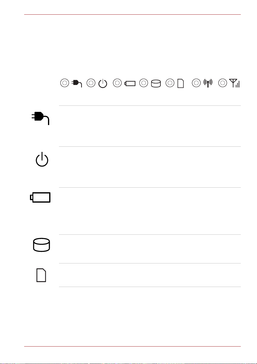
Indicators
System indicators
The Grand Tour
This section explains indicator functions.
LED system indicators next to their respective icons, glow when specific
computer operations are in progress.
Figure 2-7 System indicators
DC IN The DC IN indicator normally glows green when
power is being correctly supplied from the AC
power adaptor. However, If the output voltage
from the adaptor is abnormal, or if the computer's
power supply malfunctions, this indicator will
flash orange.
Power The Power indicator normally glows green when
the computer is turned on. However, if you turn
the computer off into Sleep Mode, this indicator
will flash orange - approximately one second on,
two seconds off - both while the system is
shutting down and while it remains turned off.
Battery The Battery indicator shows the condition of the
Hard Disk Drive/
Optical Disc Drive
Bridge media slot The Bridge media slot indicator glows green
User’s Manual 2-12
battery's charge - green indicates the battery is
fully charged, orange indicates the battery is
charging, and flashing orange indicates a low
battery condition. Please refer to Chapter 6,
Power and Power-Up Modes for more
information on this feature.
The Hard Disk Drive/Optical Disc Drive
indicator glows green whenever the computer is
accessing the built-in hard disk drive, optical disc
drive or eSATA device.
when the computer is accessing the Bridge
media slot.

The Grand Tour
Wireless
communication
The Wireless communication indicator blinks
orange when the Bluetooth and Wireless LAN
functions are turned on.
Only some models are equipped with Bluetooth
and Wireless LAN functions.
Wireless WAN The Wireless WAN indicator glows or blinks blue
when the Wireless WAN function is on.
The indicator will glow or blink in order to indicate
the connection status of the Wireless WAN
function.
A Wireless WAN module must be installed to use
this function. Some models are equipped with a
Wireless WAN module.
Keyboard indicators
The following figures show the positions of the CAPS LOCK indicator and
the keypad overlay indicators which show the following conditions:
■ When the CAPS LOCK indicator glows, the keyboard will produce
capitals when any letter is typed.
■ When the Arrow Mode indicator glows, the keypad overlay allows you to
use cursor functions.
■ When the Numeric Mode indicator glows, the keypad overlay allows
you to enter numbers.
CAPS LOCK indicator
Figure 2-8 CAPS LOCK indicator
CAPS LOCK This indicator glows green when letter keys are
locked into their uppercase format.
User’s Manual 2-13

The Grand Tour
Arrow mode
indicator
Arrow mode When the Arrow mode indicator lights green,
Numeric mode When the Numeric mode indicator lights green,
Optical disc drives
The computer is installed with a DVD-ROM, DVD-ROM&CD-R/RW or DVD
Super Multi drive. A Serial ATA interface controller is used for CD/DVDROM operation. When the computer is accessing a CD/DVD, an indicator
on the drive glows.
Some models are equipped with an optical disc drive.
For information on loading and unloading discs refer to the Using optical
disc drives section in Chapter 4, Operating Basics.
Numeric mode
indicator
Figure 2-9 Keypad overlay indicators
you can use the gray labeled keys on the keypad
overlay as cursor keys. Please refer to the
Keypad overlay section in Chapter 5, The
Keyboard for more information.
you can use the gray labeled keys on the keypad
overlay for number entry. Please refer to the
Keypad overlay section in Chapter 5, The
Keyboard for more information.
Region codes for DVD drives and media
DVD Super Multi drives and their associated media are manufactured
according to the specifications of six marketing regions. When you
purchase DVD-Video, make sure it matches your drive, otherwise it will not
play properly.
Code Region
1 Canada, United States
2 Japan, Europe, South Africa, Middle East
3 Southeast Asia, East Asia
User’s Manual 2-14

The Grand Tour
4 Australia, New Zealand, Pacific Islands, Central
5 Russia, Indian Subcontinent, Africa, North Korea,
6 China
America, South America, Caribbean
Mongolia
Writable discs
This section describes the types of writable CD/DVD discs. Check the
specifications of your drive to see the types of discs it can write. Use
TOSHIBA Disc Creator to write compact discs. Refer to Chapter 4,
Operating Basics.
CDs
■ CD-R discs can be written only once. The recorded data cannot be
erased or changed.
■ CD-RW discs including multi speed CD-RW discs, high-speed CD-RW
discs and ultra-speed CD-RW discs can be recorded more than once.
DVDs
■ DVD-R, DVD+R, DVD-R (Dual Layer) and DVD+R (Double Layer) discs
can be written only once. The recorded data cannot be erased or
changed.
■ DVD-RW, DVD+RW and DVD-RAM discs can be recorded more than
once.
Formats
The drives support the following formats.
DVD-ROM drive
The drive supports the formats CD-ROM, DVD-ROM, DVD-Video, CD-DA,
CD-Text, Photo CD
CD-ROM XA Mode 2 (Form1, Form2), Enhanced CD (CD-EXTRA) and
Addressing Method 2.
TM
(single/multi-session), CD-ROM Mode 1, Mode 2,
DVD-ROM&CD-R/RW drive
The drive supports the formats in addition to the DVD-ROM drive, and CDR, CD-RW.
User’s Manual 2-15

DVD Super Multi drive Double Layer
The drive supports the formats in addition to the DVD-ROM&CD-R/RW
drive, and DVD-R, DVD-RW, DVD+R, DVD+RW, DVD-RAM, DVD-R DL
(Format1), DVD+R DL.
Some types and formats of DVD-R DL and DVD+R DL discs may be
unreadable.
DVD-ROM drive
The full-size DVD-ROM drive module lets you run either 12 cm (4.72") or 8
cm (3.15") CD/DVDs without using an adaptor.
The read speed is slower at the center of a disc and faster at the outer
edge.
DVD read 8 speed (maximum)
CD read 24 speed (maximum)
DVD-ROM&CD-R/RW drive
The full-size DVD-ROM&CD-R/RW drive module lets you record data to
rewritable CDs as well as run either 12 cm (4.72") or 8 cm (3.15") CD/DVDs
without using an adaptor.
The read speed is slower at the center of a disc and faster at the outer
edge.
DVD read 8 speed (maximum)
CD read 24 speed (maximum)
CD-R write 24 speed (maximum)
CD-RW write 24 speed (maximum, Ultra-speed media)
The Grand Tour
User’s Manual 2-16

DVD Super Multi drive Double Layer
The full-size DVD Super Multi drive module lets you record data to
rewritable CD/DVDs as well as run either 12 cm (4.72") or 8cm (3.15")
CD/DVDs without using an adaptor.
The read speed is slower at the center of a disc and faster at the outer
edge.
DVD read 8 speed (maximum)
DVD-R write 8 speed (maximum)
DVD-R DL write 6 speed (maximum)
DVD-RW write 6 speed (maximum)
DVD+R write 8 speed (maximum)
DVD+R DL write 6 speed (maximum)
DVD+RW write 8 speed (maximum)
DVD-RAM write 5 speed (maximum)
CD read 24 speed (maximum)
CD-R write 24 speed (maximum)
CD-RW write 24 speed (maximum, Ultra-speed media)
AC adaptor
The AC adaptor can automatically adjust to any voltage ranging from 100 to
240 volts and to a frequency of either 50 or 60 hertz, enabling you to use
this computer in almost all country/region. The adaptor converts AC power
to DC power and reduces the voltage supplied to this computer.
To recharge the battery, simply connect the AC adaptor to a power source
and to the computer. Please refer to Chapter 6, Power and Power-Up
Modes for further information.
The Grand Tour
Figure 2-10 The AC adaptor (2-pin plug)
User’s Manual 2-17

The Grand Tour
Figure 2-11 The AC adaptor (3-pin plug)
■ Depending on the model in question, either a 2-pin or 3-pin
adaptor/power lead will be bundled with the computer.
■ Do not use a 3-pin to 2-pin conversion plug.
■ The supplied power cord conforms to safety rules and regulations in
the region the product is bought and should not be used outside of this
region. In order to use the adaptor/computer in other regions, you
should please buy a power cord that conforms to the safety rules and
regulations in that particular region.
Always use the TOSHIBA AC adaptor that was included with your
computer, or use AC adaptors specified by TOSHIBA to avoid any risk of
fire or other damage to the computer. Use of an incompatible AC adaptor
could cause fire or damage to the computer possibly resulting in serious
injury. TOSHIBA assumes no liability for any damage caused by use of an
incompatible adaptor.
User’s Manual 2-18

Chapter 3
Hardware, Utilities and Options
Hardware
This section describes the hardware of your computer.
The actual specifications may vary depending on the model you
purchased.
Processor
CPU Your computer is equipped with one processor
and processor type varies depending on model.
To check which type of processor is included in
your model, open the TOSHIBA PC Diagnostic
Tool Utility by clicking Start -> All Programs ->
TOSHIBA -> Utilities -> PC Diagnostic Tool.
Some models in this series use Intel® Centrino® 2 processor technology
which is based on three separate components, the Intel
processor, Intel
GM/PM45 Express Chipset.
®
Wi-Fi Link 5300AGN -OR- 5100AGN and the Intel®
®
Core™ 2 Duo
Legal Footnote (CPU)*2
For more information on the CPU, please refer to the Legal Footnotes
section in Appendix H or Click the *2 above.
User’s Manual 3-1

Memory
Hardware, Utilities and Options
Memory slots 512, 1,024, 2,048 or 4,096MB memory modules
Video RAM The memory in a computer's graphics adaptor,
If your computer is configured with more than 3 GB memory, the memory
might be displayed as approximately 3 GB only (depending on the
computer’s hardware specifications).
This is correct because the operating system usually displays the available
memory instead of the physical memory (RAM) built into the computer.
Various system components (like the video adapter’s GPU and PCI
devices like Wireless LAN, etc.) require their own memory space. Since a
32-bit operating system cannot address more than 4 GB of memory, these
system resources overlap the physical memory. It is a technical limitation
that the overlapped memory is not available to the operating system. Even
though some tools might display the actual physical memory built into your
computer, the memory available to the operating system will still be
approximately 3 GB only.
can be installed in the computer's two memory
slots for a maximum of 8,192MB system memory.
This computer can be equipped with memory
modules of a maximum size of 8,192MB. The
actual amount of useable system memory will be
less than the installed memory modules.
used to store the image displayed on a bitmap
display.
The amount of Video RAM available is
dependent on the computer's system memory.
Start -> Control Panel -> Appearance and
Personalization -> Display -> Adjust
resolution.
The amount of Video RAM can be verified by
clicking the Advanced Settings button in the
Screen Resolution window.
Legal Footnote (Memory (Main System))*3
For more information regarding Memory (Main System), please refer to the
Legal Footnotes section in Appendix H or click the *3 above.
Power
Battery pack The computer is powered by one rechargeable
lithium-ion battery pack.
User’s Manual 3-2

Hardware, Utilities and Options
Legal Footnote (Battery Life)*4
For more information regarding Battery Life, please refer to the Legal
Footnotes section in Appendix H or click the *4 above.
RTC battery The internal RTC battery backs up the Real Time
Clock (RTC) and calendar.
AC adaptor The AC adaptor provides power to the system
and recharges the batteries when they are low. It
comes with a detachable power cord which will
either have a 2-pin or 3-pin plug enclosure.
As the AC adaptor is universal, it can receive a
range of AC voltages from 100 to 240 volts,
however you should note that the output current
varies among different models. Using the wrong
adaptor can damage your computer. Refer to the
AC adaptor section in Chapter 2, The Grand
To ur .
Disks
Hard disk drive or
Solid state drive
This computer is equipped with one of the
following hard disk drive (HDD) types. The
capacity of each hard disk drive model is
different.
Some models are equipped with a "Solid State
Drive (SSD)" instead of a hard disk drive.
■ HDD
■ 80GB
■ 120GB
■ 160GB
■ 200GB
■ 250GB
■ 320GB
■ SSD
■ 64GB
■ 128GB
Please note that part of the hard disk or Solid
state drive's overall capacity is reserved as
administration space. Additional HDD/SSD drive
sizes may be introduced.
User’s Manual 3-3

Hardware, Utilities and Options
■ In this manual, the word "HDD" or "Hard disk drive" also refers to the
SSD unless otherwise stated.
■ SSD is a large-capacity storage media which uses Solid-State Memory
in place of a magnetic disk of the hard disk.
Under certain unusual conditions of prolonged non-use and/or exposure to
high temperatures, the SSD may be vulnerable to data retention errors.
Legal Footnote (Hard Disk Drive (HDD) Capacity)*5
For more information regarding Hard Disk Drive (HDD) Capacity, please
refer to the Legal Footnotes section in Appendix H or click the *5 above.
Optical disc drive
Drive The following optical disc drive is pre-installed in
this computer.
■ DVD-ROM drive
■ DVD-ROM&CD-R/RW drive
■ DVD Super Multi drive Double Layer
2.6GB and 5.2GB DVD-RAM media cannot be read from or written to.
Display
The computer's internal display panel supports high-resolution video
graphics and can be set to a wide range of viewing angles for maximum
comfort and readability.
Display panel
User’s Manual 3-4
■ TECRA A10/S10/P10, Satellite S300L,
Satellite Pro S300/S300L
15.4” TFT LCD screen, 16 million colors, with
one of the following resolutions:
■ WXGA, 1280 horizontal x 800 vertical
pixels
■ WSXGA+, 1680 horizontal x 1050 vertical
pixels
■ TECRA M10
14.1” TFT LCD screen, 16 million colors, with
one of the following resolutions:
■ WXGA, 1280 horizontal x 800 vertical
pixels
■ WXGA+, 1440 horizontal x 900 vertical
pixels

Hardware, Utilities and Options
Legal Footnote (LCD)*6
For more information regarding the LCD, please refer to the Legal
Footnotes section in Appendix H or click the *6 above.
Graphics controller The graphics controller maximizes display
performance. Refer to Display Controller and
Video mode section in Appendix B for more
information.
Legal Footnote (Graphics Processor Unit ("GPU"))*7
For more information regarding the Graphics Processor Unit ("GPU"),
please refer to the Legal Footnotes section in Appendix H or click the *7
above.
Sound
Sound system The integrated sound system provides support
for the computer's internal speakers and
microphone, as allowing an external microphone
and headphones to be connected via the
appropriate jacks.
Multimedia
Web Camera Web Camera is a device that allows you to
record video or take photographs with your
computer. You can use it for video chatting or
video conferences using a communication tool
such as Windows Live Messenger. TOSHIBA
Web Camera Application will help you to add
various video effects to your video or photograph.
Please refer to the Web Camera section in
Chapter 4, Operating Basics.
User’s Manual 3-5

Communications
Hardware, Utilities and Options
Modem The integrated modem provides capability for
LAN The computer has built-in support for Ethernet
Bluetooth Some computers in this series have Bluetooth
Wireless LAN Some computers in this series are equipped with
data and fax communications that support the
V.90 (V.92) standards and includes a modem
jack for connection to the telephone line. Please
note that both the V.90 and V.92 standards are
only supported in the USA, Canada, United
Kingdom, France, Germany and Australia - only
the V.90 standard is supported in other regions.
You should also be aware that the speed of data
and fax transfer will depend on the analog
telephone line conditions.
Some models are equipped with the integrated
modem.
LAN (10 megabits per second, 10BASE-T), Fast
Ethernet LAN (100 megabits per second,
100BASE-TX) and Gigabit Ethernet LAN (1000
megabits per second, 1000BASE-T).
wireless communication function which
eliminates the need for cables between
electronic devices such as computers, printers
and mobile phones. When it is enabled,
Bluetooth provides the wireless personal area
network environment which is safe and
trustworthy, that is quick and easy.
a Wireless LAN module that is compatible with
other LAN systems based on Direct Sequence
Spread Spectrum/Orthogonal Frequency Division
Multiplexing radio technology that complies with
the IEEE 802.11 Standard.
Legal Footnote (Wireless LAN)*8
For more information regarding Wireless LAN, please refer to the Legal
Footnotes section in Appendix H or click the *8 above.
Special features
The following features are either unique to TOSHIBA computers or are
advanced features which make the computer more convenient to use.
Access each function using the following procedures.
*1 To access the Power Options, click Start -> Control Panel -> System
and Security -> Power Options.
User’s Manual 3-6

Hardware, Utilities and Options
TOSHIBA Assist
button
Press this button to launch the program
automatically. When power-off, Sleep Mode and
Hibernation Mode, press this button to start the
computer and launch the program.
Some models are equipped with a TOSHIBA
Assist button.
TOSHIBA
Presentation button
The TOSHIBA Presentation button has the same
functionality as the Connect display button in the
Mobility Center.
Some models are equipped with a TOSHIBA
Presentation button.
Hot keys Hot keys are specific key combinations that let
you quickly change the system configuration
directly from the keyboard without running a
system program.
Display automatic
power off
*1
This feature automatically cuts off power to the
computer's display panel when there is no
keyboard input for a specified time, with power
being restored the next time a key is pressed.
This can be specified in the Power Options.
HDD automatic
power off
*1
This feature automatically cuts off power to the
hard disk drive when it is not accessed for a
specified time, with power being restored when
the hard disk drive is next accessed. This can be
specified in the Power Options.
System automatic
Sleep/Hibernation
*1
Mode
This feature automatically shuts down the system
into either Sleep Mode or Hibernation Mode when
there is no input or hardware access for a
specified time. This can be specified in the Power
Options.
Keypad overlay A ten-key numeric keypad is integrated into the
keyboard. Please refer to the Keypad overlay
section in Chapter 5, The Keyboard, for
information on using this feature.
Power on password Two levels of password security, supervisor and
user, are available to prevent unauthorized
access to your computer.
Instant security A specific hot key function automatically locks the
system providing data security.
User’s Manual 3-7

Hardware, Utilities and Options
Intelligent power
supply
*1
Battery save mode
Panel power on/off
*1
Low battery
automatic
Hibernation Mode
Heat dispersal
*1
TOSHIBA HDD
Protection
A microprocessor in the computer's intelligent
power supply detects the battery's charge,
automatically calculates the remaining battery
capacity and protects electronic components
from abnormal conditions such as a voltage
overload from the AC adaptor. This can be
specified in the Power Options.
*1
This feature lets you configure the computer in
order to save battery power. This can be
specified in the Power Options.
This feature automatically turns power to the
computer off when the display panel is closed,
and turns it back on when the display panel is
opened. This can be specified in the Power
Options.
When battery power is exhausted to the point that
computer operation cannot be continued, the
*1
system automatically enters Hibernation Mode
and shuts itself down. This can be specified in the
Power Options.
To protect against overheating, the processor has
an internal temperature sensor so that, if the
computer's internal temperature rises to a certain
level, the cooling fan is turned on or the
processing speed is lowered. This can be
specified in the Power Options.
This feature uses the acceleration sensor built in
the computer to detect vibration and shocks, and
automatically moves the hard disk drive's
read/write head to a safe position in order to
reduce the risk of damage that could be caused
by head-to-disk contact. Refer to the Using the
Hard Disk Drive (HDD) Protection section in
Chapter 4, Operating Basics, for more details.
■ The TOSHIBA HDD Protection function does not guarantee that the
hard disk drive will not be damaged.
■ TOSHIBA HDD Protection cannot be used in models that are equipped
with SSD.
User’s Manual 3-8

Hardware, Utilities and Options
Hibernation Mode This feature lets you turn off the power to the
computer without exiting from your software. The
contents of main memory are automatically
saved to the hard disk drive so that when you
next turn the power on again, you can continue
working right where you left off. Refer to the
Turning off the power section in Chapter 1,
Getting Started, for more details.
Sleep Mode If you have to interrupt your work, you can use
this feature to allow you to turn off power to the
computer without exiting from your software.
Data is maintained in the computer's main
memory so that when you next turn on the power,
you can continue working right where you left off.
USB Sleep and
Charge function
This feature allows you to charge USBcompatible external devices such as mobile
phones or portable digital music players via the
USB port when your computer is in Sleep Mode,
Hibernation Mode or in the shutdown state.
This function is worked by the USB Sleep and
Charge Utility. For more information, please refer
to the Using the TOSHIBA USB Sleep and
Charge Utility section in Chapter 4, Operating
Basics.
USB Wakeup
function
This function restores the computer from Sleep
Mode depending on the external devices
connected to the USB ports.
For example, if a mouse or USB keyboard is
connected to a USB port, moving the
mouse/keyboard will wakeup the computer.
The "USB Wakeup function" operates under
Windows 7 operating system and it works for all
USB ports.
TOSHIBA PC Health
Monitor
The TOSHIBA PC Health Monitor application
proactively monitors a number of system
functions such as power consumption, battery
health and system cooling, informing you of
significant system conditions. This application
recognizes the system and individual component
serial numbers and will track specific activities
related to their usage.
Refer to Appendix G, TOSHIBA PC Health
Monitor.
User’s Manual 3-9

TOSHIBA Value Added Package
This section describes the TOSHIBA Component features pre-installed on
the computer.
Hardware, Utilities and Options
TOSHIBA Power
Saver
TOSHIBA Button
Support
TOSHIBA Button Support cannot be used in models that are not equipped
with TOSHIBA Assist button and TOSHIBA Presentation button.
TOSHIBA Zooming
Utility
TOSHIBA PC
Diagnostic Tool
TOSHIBA Password
Utility
TOSHIBA Flash
Cards
TOSHIBA Power Saver provides you with the
features of more various power supply
managements.
This utility controls the following computer button
functions.
■ TOSHIBA Assist
■ TOSHIBA Presentation
The starting application from the button can be
changed.
This utility allows you to enlarge or reduce the
icon size on the Windows Desktop, or the zoom
factor associated with specific supported
applications.
The TOSHIBA PC Diagnostic Tool will display
basic system configuration information and allow
the functionality of some of the computer's builtin hardware devices to be tested.
The TOSHIBA Password utility allows you to set
a password in order to restrict access to the
computer.
The TOSHIBA Flash Cards provide a quick way
to modify selected system functions and to
launch applications.
■ Hot key function
■ TOSHIBA utility launcher function
User’s Manual 3-10

Hardware, Utilities and Options
HW Setup This utility allows you to customize your
hardware settings according to the way you work
with the computer and the peripherals you use.
TOSHIBA
Accessibility
Utilities and Applications
This section describes the pre-installed utilities that come with the
computer and details how to start them. For further information on their
operation, please refer to each utility's online manual, help files or
README.TXT file.
Fingerprint Utility This product has a fingerprint utility installed for
The TOSHIBA Accessibility utility provides
support to movement impaired users when they
need to use the TOSHIBA Hot-key functions. In
use, the utility allows you to make the FN key
'sticky', that is you can press it once, release it,
and they press one of the 'Function' keys in
order to access its specific function. When set,
the FN key will remain active until another key is
pressed.
the purpose of enrolling and recognizing
fingerprints which can then be linked to a
username and password in order to remove the
need to input these details from the keyboard.
Just by swiping an enrolled finger against the
fingerprint sensor, the following functions will be
enabled:
■ Logon to Windows and access a security
enabled homepage through Internet Explorer.
■ Files and folders can be encrypted/decrypted
and third party access to them is prevented.
■ Disable the password-protected screen-saver
when returning from a power-saving mode
such as Sleep Mode.
■ Authentication of the User Password (and, if
applicable, the HDD(Hard Disk Drive)
Password) when booting up the computer
(Power-on Security).
■ Single Sign-on feature
Fingerprint security cannot be used in models that do not have a fingerprint
module installed.
User’s Manual 3-11

Hardware, Utilities and Options
TOSHIBA Face
Recognition
TOSHIBA Face Recognition uses a face
verification library to verify the face data of users
when they log in to Windows. If the verification is
successful, the user will be logged into Windows
automatically. The user can thus avoid having to
enter a password or the like, which makes the
login process easier.
TOSHIBA DVD
Player
This software is provided for playback of DVD
Video.
It has an on-screen interface and functions. Click
Start -> All Programs -> TOSHIBA DVD
PLAYER -> TOSHIBA DVD PLAYER.
For details on how to use TOSHIBA DVD
PLAYER, see the help file.
■ Frame dropping, audio skipping or out of synch audio and video may
occur during playback of some DVD Video titles.
■ Make sure to connect the computer's AC adaptor when playing a DVD
Video. Power-saving features may interfere with smooth playback.
■ If you see the screen blinking while playing DVD with subtitle on at
Media Player, please use TOSHIBA DVD Player or Media Center to
play DVD.
Bluetooth Stack for
Windows by Toshiba
This software enables communication between
the computer and external Bluetooth devices
such as printers and mobile phones.
Bluetooth functions cannot be used in models that do not have a Bluetooth
module installed.
TOSHIBA SD
Memory Boot Utility
The TOSHIBA SD Memory Boot Utility allows
you to create a bootable SD memory card to start
the system. You can boot TOSHIBA SD Memory
Boot Utility from the menu bar as follows. Click
Start -> All Programs -> TOSHIBA -> Utilities
-> SD Memory Boot Utility.
SD Memory Card Format Utility and other SD functions are packaged into
TOSHIBA SD Memory Utilities.
User’s Manual 3-12

Hardware, Utilities and Options
TOSHIBA SD
Memory Card Format
This utility allows you to format an SD/SDHC
memory card by the SD standard format.
TOSHIBA Assist TOSHIBA Assist is a graphical user interface that
provides access to specific tools, utilities and
applications that make the use and configuration
of the computer easier.
TOSHIBA ConfigFree TOSHIBA ConfigFree is a suite of utilities that
improve the ease and control of communication
devices and network connections, help in the
identification of communication problems and
allow the creation of profiles if you need to switch
between different locations and communication
networks. To access this utility, click Start -> All
Programs -> TOSHIBA -> ConfigFree.
TOSHIBA Mic Effect TOSHIBA Mic Effect provides you the Echo
Canceller and the Microphone Array functions.
For more instructions for this software, refer to
the Sound System section in Chapter 4,
Operating Basics.
TOSHIBA eco Utility This PC is equipped with "eco mode". This mode
slightly lowers performance of some devices to
reduce electric power consumption. You can
realize measurable power savings by using it
continuously. TOSHIBA eco Utility helps you
monitor your power savings by showing
approximate real time power consumption.
Furthermore, it shows approximate accumulated
power consumption and approximate
accumulated power savings when using eco
mode daily, weekly, and monthly. You can track
power savings by using eco mode continuously.
TOSHIBA Disc
Creator
You can create CD's and DVD's in a number of
formats including audio CD's that can be played
on a standard CD player, and data CD's/DVD's
which can store copies of the files and folders on
your computer's hard disk drive. This software
can be used on models with a DVD Super Multi
drive.
To start this utility, click Start -> All Programs ->
TOSHIBA -> CD&DVD Applications -> Disc
Creator.
User’s Manual 3-13

Hardware, Utilities and Options
TOSHIBA DVD-RAM
Utility
TOSHIBA HDD/SSD
Alert Utility
TOSHIBA Service
Station
Display Rotation
Settings
This utility has the function of Physical Format
and Write-Protect to DVD-RAM. This utility is
contained the setup module of TOSHIBA Disc
Creator. To start this utility, click Start -> All
Programs -> TOSHIBA -> CD&DVD
Applications -> DVD-RAM Utility.
This utility includes wizard functions to monitor
the Disk Drive operating status and execute the
system backup.
To access the utility, click Start -> All Programs
-> TOSHIBA -> Utilities -> HDD SSD Alert.
This application allows your computer to
automatically search for TOSHIBA software
updates or other alerts from TOSHIBA that are
specific to your computer system and its
programs. When enabled, this application
periodically transmits to our servers a limited
amount of system information, which will be
treated in strict accordance with the rules and
regulations as well as applicable data protection
law.
To access this utility, click Start -> All Programs
-> TOSHIBA -> Utilities -> Service Station.
This utility allows you to quickly rotate the
Windows Desktop by either 0 degrees and 180
degrees. In use you are able to perform a
rotation function by pressing either CTRL + ALT
+ Up Arrow ( ) to rotate 0 degrees or CTRL
+ ALT + Down Arrow ( ) to rotate 180
degrees - in a multi-monitor setup, the display
that contains the cursor will be affected by these
changes.
User’s Manual 3-14

Hardware, Utilities and Options
Windows Mobility
Center
TOSHIBA USB Sleep
and Charge Utility
Trusted Platform
Module (TPM)
Mobility Center is a utility for accessing several
mobile PC settings quickly in one window. A
default maximum of eight tiles are provided by
the operating system, and the additional two tiles
are added to your Mobility Center.
■ Lock Computer:
This can be used to lock your computer
without turning it off. This has the same
function as selecting Lock from the Start
menu (click Start, point to the arrow icon
( ) and then select Lock
from the menu).
■ TOSHIBA Assist:
This can be used to open TOSHIBA Assist if
it is already installed in your computer.
This utility is able to either enable or disable the
USB Sleep and Charge function.
Shows the positions of USB ports that support
the USB Sleep and Charge function and displays
the battery's remaining capacity.
To start this utility, click Start -> All Programs ->
TOSHIBA -> Utilities -> USB Sleep and
Charge.
The TPM (Trusted Platform Module) is a security
encryption device for the hard disk drive.
BIOS setup and Infineon TPM Software
Professional Package must be configured in
order to use TPM.
To enable TPM through the BIOS setup:
1. Turn on the computer while pressing the ESC key.
2. Press the F1 key when directed.
3. Press the PGDN key.
4. Set the TPM in SECURITY CONTROLLER to Enabled.
5. Press the Y key to save the changes.
6. Press END and then press the Y key to accept the changes. The
computer will restart.
In order to change the TPM setting when the Hide TPM setting is currently
set to Yes, switch the Hide TPM setting from Yes to No.
User’s Manual 3-15

Optional devices
Optional devices can expand the computer's capabilities and its versatility.
This section describes the connection or installation of the following
devices:
Cards/memory
■ ExpressCard/PC Card
■ Smart Card
■ Bridge media slot
■ Secure Digital™ (SD) Card (SD memory card, SDHC memory card,
miniSD Card, microSD Card)
■ Memory Stick (Memory Stick, Memory Stick PRO, Memory Stick
PRO Duo)
■ xD picture card
■ MultiMediaCard
■ Additional memory module
Peripheral devices
■ Hard disk drive pack
■ External monitor
■ USB FDD Kit
■ eSATA
■ i.LINK (IEEE1394)
■ Serial port
■ TOSHIBA Express Port Replicator
Hardware, Utilities and Options
Other
■ Security lock
ExpressCard
The computer is equipped with a single ExpressCard slot into which any
ExpressCard device that meets industry standards, either manufactured by
TOSHIBA or another vendor, can be installed. The slot supports hot plug
connection and utilizes the PCI Express interface that supports the reading
and writing of data at a theoretical maximum rate of 2.5Gbps.
Inserting an ExpressCard
The Windows hot-install feature allows you to insert ExpressCards while
the computer is turned on.
Do not insert an ExpressCard while the computer is in Sleep Mode or
Hibernation Mode as you may find that some cards do not work properly.
User’s Manual 3-16

Hardware, Utilities and Options
To insert an ExpressCard, follow the steps as detailed below:
1. Press the Dummy card in order to eject the Dummy card partially out of
the computer.
2. Grasp the Dummy card and draw it.
3. Insert the ExpressCard into the ExpressCard slot on the side of the
computer.
4. Press the ExpressCard gently to ensure a firm connection is made.
ExpressCard slot
ExpressCard
Figure 3-1 Inserting the ExpressCard (ExpressCard Model)
5. After inserting the ExpressCard you should refer to its documentation
and also check the configuration in Windows in order to ensure that it is
correct.
Removing an ExpressCard
To remove an ExpressCard, follow the steps as detailed below.
1. Open the Safely Remove Hardware icon on the Windows Taskbar.
2. Point to ExpressCard and click the left Touch Pad control button.
3. Press the ExpressCard in order to eject the ExpressCard partially out of
the computer.
4. Grasp the ExpressCard and remove it.
User’s Manual 3-17
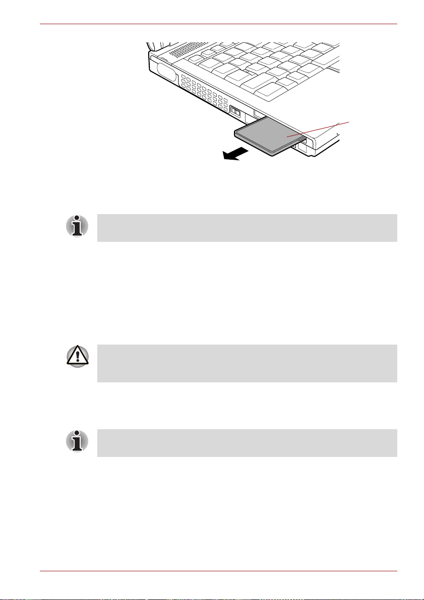
Hardware, Utilities and Options
Figure 3-2 Removing the ExpressCard (ExpressCard Model)
5. Insert the Dummy card into the ExpressCard slot.
When you do not use an ExpressCard, please be sure to insert a Dummy
card.
PC Card
The computer is equipped with a single PC Card slot that can
accommodate a Type II format card. Any PC Card that meets industry
standards, either manufactured by TOSHIBA or another vendor, can be
installed as the slot supports 16-bit PC Cards and 32-bit CardBus cards.
For reference, CardBus supports the newer standard of 32-bit PC Cards
and provides superior performance for the greater demands of applications
such as multimedia data transmission.
ExpressCard
PC Cards can sometimes become hot during computer operation. Before
you remove a PC Card always wait for it to cool. You could get burned
removing a hot PC Card.
Inserting a PC Card
The Windows hot-install feature allows you to insert PC Cards while the
computer is turned on.
Do not insert a PC Card while the computer is in Sleep Mode or
Hibernation Mode as you may find that some cards do not work properly.
To insert a PC Card, follow the steps as detailed below:
1. Insert the PC Card into the PC Card slot on the side of the computer.
2. Press the PC Card gently to ensure a firm connection is made.
User’s Manual 3-18

Hardware, Utilities and Options
PC Card slot
PC Card
Figure 3-3 Inserting the PC Card
3. After inserting the PC Card you should refer to its documentation and
also check the configuration in Windows in order to ensure that it is
correct.
Removing a PC Card
To remove a PC Card, follow the steps as detailed below:
1. Open the Safely Remove Hardware icon on the Windows Taskbar.
2. Point to PC Card and click the left Touch Pad control button.
3. Press the PC Card eject button to partially extend it out of the computer.
If the PC Card is not inserted all the way into the computer, the eject button
may not cause it to pop out sufficiently to allows it to be grasped. In this
instance, simply push the PC Card firmly back into the computer and then
press the eject button again.
4. Press the extended PC Card eject button in order to eject the PC Card
partially out of the computer.
5. Grasp the PC Card and remove it.
PC Card
PC Card
eject button
Figure 3-4 Removing the PC Card
User’s Manual 3-19

Hardware, Utilities and Options
Smart Card
A Smart Card is a credit card sized plastic card. An extremely thin
integrated circuit (IC chip) is embedded into the card on which information
can be recorded. These cards can be used for a wide variety of
applications including telephone related and electronic monetary payments.
This section contains information on the proper use of the Smart Card slot,
and it is strongly recommended that you read it before operating the
computer.
Some models are equipped with a Smart Card slot.
■ Your computer supports ISO7816-3 asynchronous cards (support
protocols are T=0 and T=1) with a working voltage of 5V.
■ The computer is equipped with either a PC Card slot or a Smart Card
slot.
Inserting a Smart Card
The Smart Card slot is located on the left side of the computer. The
Windows hot-install feature allows you to insert a Smart Card while the
computer is turned on.
To install a Smart Card, follow the steps as detailed below:
1. Insert the Smart Card into the Smart Card slot with the metal
connectors facing up.
2. Press the Smart Card gently to ensure a firm connection is made. The
computer will identify the Smart Card and display an icon in the
Windows Taskbar.
■ When inserting a Smart Card into the Smart Card slot, make sure to
confirm that the card is oriented correctly before inserting.
■ Insert the Smart Card until it reaches the end of the Smart Card slot.
There will be about 2cm of the Smart Card sticking out of the Smart
Card slot. Do not attempt to insert it further.
■ Always remove the Smart Card from the Smart Card slot before moving
the computer.
■ Remove the Smart Card after use.
Failure to follow these instructions may result in damage to the computer
and/or damage to the Smart Card.
User’s Manual 3-20

Hardware, Utilities and Options
Smart Card
Figure 3-5 Inserting a Smart Card
3. After inserting the Smart Card, you should refer to its documentation
and also check the configuration in Windows in order to ensure that it is
correct.
Removing a Smart Card
To remove a Smart Card, follow the steps as detailed below:
1. Open the Safely Remove Hardware icon on the Windows Taskbar.
■ Before removing the Smart Card, confirm that the Smart Card is not
working with any program or system.
■ Be careful not to bend the Smart Card while removing it from the
computer.
2. Point to Smart Card and click the left Touch Pad control button.
3. Grasp the Smart Card and remove it.
Smart Card
Figure 3-6 Removing a Smart Card
User’s Manual 3-21
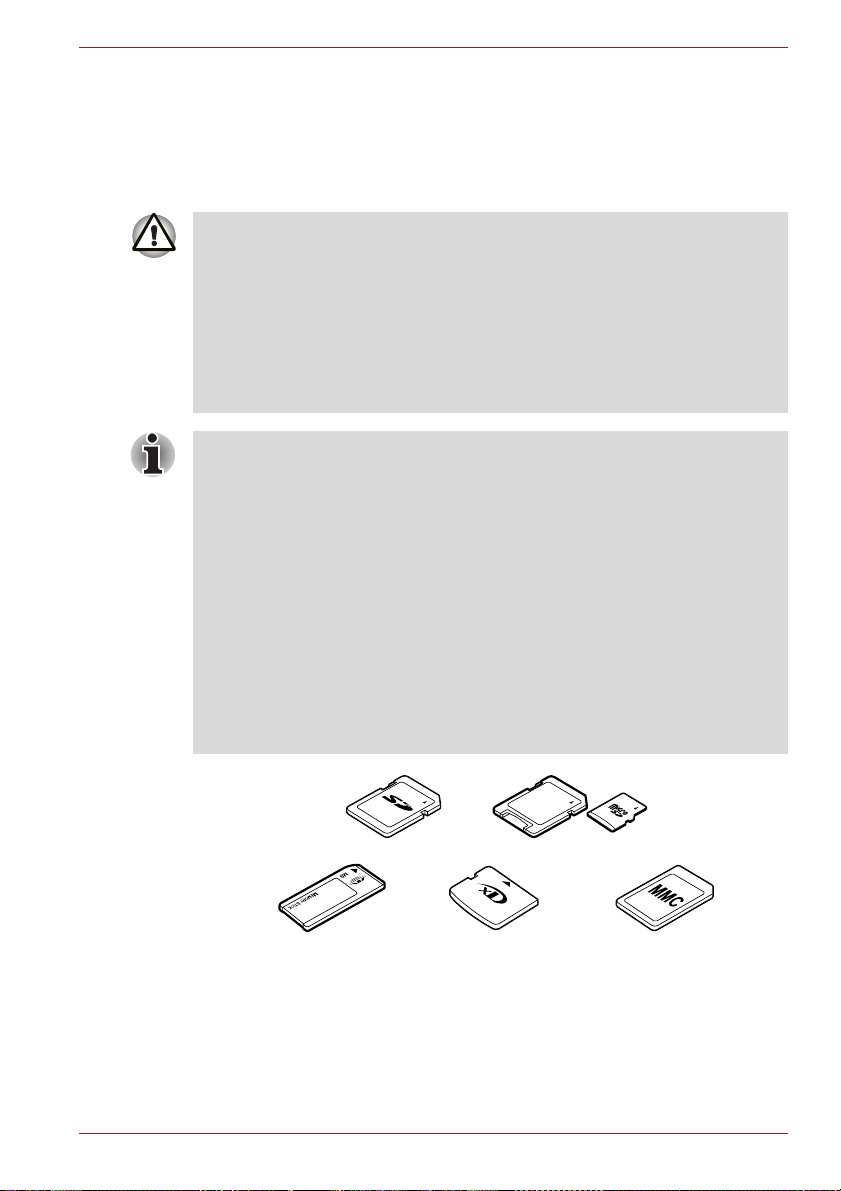
Bridge media slot
The computer is equipped with a Bridge media slot that can accommodate
some kinds of memory media with various memory capacities so that you
can easily transfer data from devices, such as digital cameras and
Personal Digital Assistants.
■ Keep foreign objects out of the Bridge media slot. Never allow metal
objects, such as screws, staples and paper clips, to enter the computer
or Keyboard. Foreign metal objects can create a short circuit, which
can cause computer damage and fire, possibly resulting in serious
injury.
■ Memory Stick Duo is not compatible with the Bridge media slot. Do not
insert Memory Stick Duo into the slot or you may not be able to remove
it. Data may be lost or damaged if you use any memory media other
than those supported.
■ This Bridge media slot supports the following memory media.
■ Secure Digital (SD) Card (SD memory card, SDHC memory card,
miniSD Card, microSD Card)
■ Memory Stick (Memory Stick, Memory Stick PRO, Memory Stick
PRO Duo)
■ xD picture card
■ MultiMediaCard (MMC™)
■ Please note that an adaptor is required to use miniSD/microSD Card.
■ Please note that an adaptor is required to use Memory Stick PRO Duo.
■ Please note that not all memory media have been tested and verified to
work correctly. Therefore, it is not possible to guarantee that all
memory media will operate properly.
■ The slot does not support Magic Gate functions.
Hardware, Utilities and Options
Secure Digital (SD) Card
Memory Stick
Figure 3-7 Examples of memory media
User’s Manual 3-22
microSD card adaptor and microSD card
xD picture card
MultiMediaCard
(MMC)

Hardware, Utilities and Options
Memory media
This section provides the important safety precautions in order to handle
your memory media.
Points to note about the SD/SDHC memory card
SD/SDHC memory cards comply with SDMI (Secure Digital Music
Initiative), which is a technology adopted to prevent unlawful copy or
playback of digital music. For this reason, you cannot copy or playback
protected material on another computer or other device, and you may not
reproduce any copyrighted material except for your personal enjoyment.
Below is a simple explanation for distinguishing SD memory cards from
SDHC memory cards.
■ SD and SDHC memory cards appear the same externally. However, the
logo on SD and SDHC memory cards is different, so pay careful
attention to the logo when purchasing.
■ The SD memory card logo is ( ).
■ The SDHC memory card logo is ( ).
■ The maximum capacity of SD memory cards is 2GB. The maximum
capacity of SDHC memory cards is 16GB.
Card Type Capacities
SD 8MB, 16MB, 32MB, 64MB, 128MB, 256MB,
SDHC 4GB, 8GB, 16GB
512MB, 1GB, 2GB
Memory media format
New media cards are formatted according to specific standards. If you wish
to reformat a media card, be sure to do so with a device that uses media
cards.
Formatting an SD/SDHC memory card
SD/SDHC memory cards are sold already formatted in conformity to
specific standards. If you format the SD/SDHC memory card again, be sure
to format it with the TOSHIBA SD Memory Card Format utility, not with the
format command provided within Windows.
In order to run the TOSHIBA SD Memory Card Format utility, click Start ->
All Programs -> TOSHIBA -> Utilities -> SD Memory Card Format.
The TOSHIBA SD Memory Card Format utility does not format the
protected area of the SD/SDHC memory card - should you need to format
all areas of the memory card, including the protected area, you will need to
obtain an appropriate application that applies the copy protection system.
User’s Manual 3-23

Hardware, Utilities and Options
Media care
Observe the following precautions when handling the card.
Card care
■ Do not twist or bend cards.
■ Do not expose cards to liquids or store in humid areas or lay media
close to containers of liquid.
■ Do not touch the metal part of a card or expose it to liquids or let it get
dirty.
■ After using card, return it to its case.
■ The card is designed so that it can be inserted only one way. Do not try
to force the card into the slot.
■ Do not leave a card partially inserted in the slot. Press the card until you
hear it click into place.
Memory card care
■ Set the write-protect switch to the lock position, if you do not want to
record data.
■ Memory cards have a limited lifespan, so it is important to backup
important data.
■ Do not write to a card if the battery power is low. Low power could affect
writing accuracy.
■ Do not remove a card while read/write is in progress.
For more details on using memory cards, see manuals accompanying the
cards.
About the write-protect
The following memory media have a function for protect.
■ SD Card (SD memory card, SDHC memory card)
■ Memory Stick (Memory Stick, Memory Stick PRO, Memory Stick PRO
Duo)
■ MultiMediaCard (MMC)
Set the write-protect switch to the lock position, if you do not want to record
data.
Inserting a memory media
The following instructions apply to all types of supported media devices. To
insert a memory media, follow the steps as detailed below:
1. Turn the memory media so that the contacts (metal areas) are face
down.
2. Insert the memory media into the Bridge media slot on the side of the
computer.
User’s Manual 3-24

Hardware, Utilities and Options
3. Press the memory media gently to ensure a firm connection is made.
Bridge media slot
Memory media
Figure 3-8 Inserting a memory media
■ Make sure memory media is oriented properly before you insert it. If
you insert the media in wrong direction, you may not be able to remove
it.
■ When inserting memory media, do not touch the metal contacts. You
could expose the storage area to static electricity, which can destroy
data.
■ Do not turn the computer off or switch to Sleep Mode or Hibernation
Mode while files are being copied - doing so may cause data to be lost.
Removing a memory media
The following instructions apply to all types of supported media devices. To
remove a memory media, follow the steps as detailed below:
1. Open the Safely Remove Hardware icon on the Windows Taskbar.
2. Point to memory media and click the left Touch Pad control button.
3. Press the memory media to partially extend it out of the computer.
4. Grasp the media and remove it.
Bridge media slot
Memory media
Figure 3-9 Removing memory media
User’s Manual 3-25

Hardware, Utilities and Options
■ Make sure the Bridge Media slot indicator is out before you remove
the memory media or turn off the computer’s power. If you remove the
memory media or turn off the power while the computer is accessing
the memory media, you may lose data or damage the media.
■ Do not remove the memory media while the computer is in Sleep or
Hibernation Mode. The computer could become unstable or data in the
memory media could be lost.
■ Do not remove only the miniSD/microSD Card while leaving the
adaptor in the Bridge Media slot.
Additional memory module
You can install additional memory into the computer in order to increase the
amount of system memory that is available. This section describes how to
install and remove optional memory modules.
■ You should place a mat beneath the computer in order to prevent the
computer's lid from becoming scratched or damaged when you are
installing/replacing the memory module. In this instance you should
avoid mats that are made of materials that hold or generate static
electricity.
■ When installing or removing a memory module, you must ensure that
you do not touch any other internal areas of the computer.
■ Insert the two memory modules into Slot A and Slot B respectively. The
computer will operate in dual channel mode.
You can access the inserted memory modules efficiently in dual
channel.
■ Use only memory modules approved by TOSHIBA.
■ Do not try to install or remove a memory module under the following
conditions.
a. The computer is turned on.
b. The computer was shut down in either Sleep or Hibernation Mode.
c. Wake-up on LAN is enabled.
d. The wireless communication switch is turned on.
■ Be careful not to let screws or other foreign matter fall into the
computer. It could cause malfunction or electric shock.
■ Additional memory module is a precision electronic component that
may be fatally damaged by static electricity. Since the human body can
carry static electricity, it is important that you discharge yourself before
touching or installing any additional memory modules. To discharge
your body’s static electricity, simply touch any metal close to you with
bare hands.
User’s Manual 3-26

Hardware, Utilities and Options
Point to note about memory module error
If you install a memory module that is not compatible with the computer, the
Power indicator will flashes (on for 0.5 seconds, off for 0.5 seconds) in the
following ways;
■ If there is an error in only Slot A or no memory module is inserted in Slot
A: repeatedly flashes orange twice, then green.
■ If there is an error in Slot B: repeatedly flashes orange, then green
twice.
■ If there are errors in both Slot A and Slot B: repeatedly flashes orange
twice, then green twice.
In all instances you should shut down the computer and remove the
incompatible module(s).
Use a point size 0 Phillips screwdriver to remove and fasten the screws the use of an incorrect screwdriver can damage the screw heads.
Installing a memory module
To install a memory module, follow the steps as detailed below:
1. Shut down the computer - make sure the Power indicator is off (refer to
the Turning off the power section in Chapter 1, Getting Started if
required).
2. Remove the AC adaptor and all cables and peripherals connected to
the computer.
3. Close the display panel.
4. Turn the computer upside down and remove the battery pack (refer to
Replacing the battery pack section in Chapter 6, Power and Power-Up
Modes, if required).
5. Loosen the one screw securing the memory module cover in place please note that this screw is attached to the cover in order to prevent it
from being lost.
Use a point size 0 Phillips screwdriver.
User’s Manual 3-27

Hardware, Utilities and Options
6. Slide your fingernail or a thin object under the cover and lift it off.
Memory
module cover
Screw
Figure 3-10 Removing the memory module cover
7. Align the notch of the memory module with that of the memory slot and
gently insert the module into the slot at about a 45 degree angle before
holding it down until the latches on either side snap into place.
Notch
Slot B
Slot A
Figure 3-11 Seating the memory module
■ Never allow metal objects, such as screws, staples and paper clips, to
enter the computer. Foreign metal objects can create a short circuit,
which can cause computer damage and fire, possibly resulting in
serious injury.
■ Do not touch the connectors on the memory module or on the
computer. Debris on the connectors may cause memory access
problems.
User’s Manual 3-28
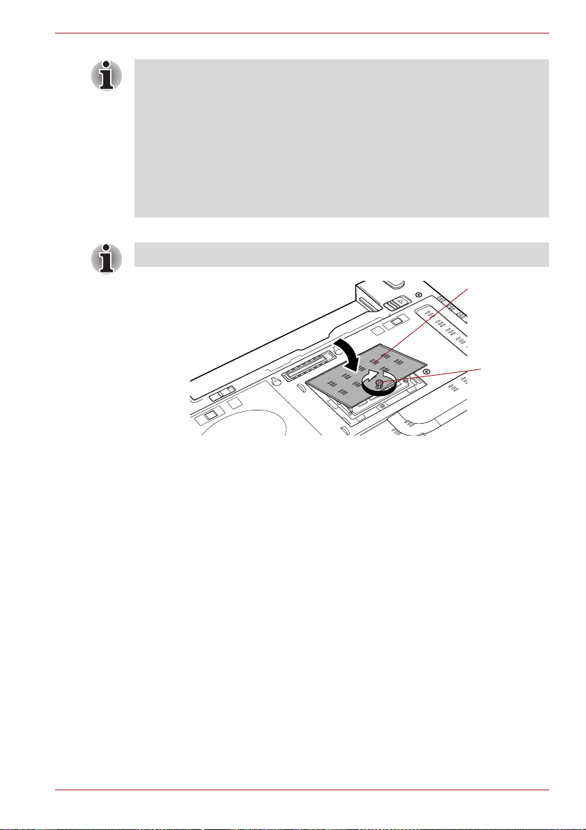
Hardware, Utilities and Options
■ The slot A is reserved for the first memory module. Use the slot B for
expanded memory. If only one module is installed, use the slot A. When
inserting or removing memory modules, use the A and B marked on the
computer chassis to determine which slot is A and which is B.
■ Align the grooves along the edges of the memory module with the
locking tabs on the connector and insert the module into the connector
firmly - if you find it difficult to install the memory module, gently prise
the locking tabs outwards using the tip of your finger.
Please also ensure that you hold the memory module along its left and
right hand edges - the edges with the grooves in.
8. Seat the memory module cover in place and secure it with one screw.
Take care to ensure that the memory module cover is firmly closed.
Memory
module cover
Screw
Figure 3-12 Seating the memory module cover
9. Install the battery pack - refer to Replacing the battery pack section in
Chapter 6, Power and Power-Up Modes, if required.
10. Turn your computer over.
11. Turn the computer on and make sure the added memory is recognized to confirmed it, Start -> Control Panel -> System and Security ->
System icon.
Removing a memory module
To remove the memory module, follow the steps as detailed below:
1. Shut down the computer - make sure the Power indicator is off (refer to
the Turning off the power section in Chapter 1, Getting Started if
required).
2. Remove the AC adaptor and all cables and peripherals connected to
the computer.
3. Close the display panel.
4. Turn the computer upside down and remove the battery pack (refer to
Replacing the battery pack section in Chapter 6, Power and Power-Up
Modes, if required).
User’s Manual 3-29

Hardware, Utilities and Options
5. Loosen the one screw securing the memory module cover in place please note that this screw is attached to the cover in order to prevent it
from being lost.
6. Slide your fingernail or a thin object under the cover and lift it off.
7. Push the latches away from the module in order to release it - a spring
will force one end of the module up at an angle.
8. Grasp the module by its edges and remove it from the computer.
■ If you use the computer for a long time, the memory modules and the
circuits locating close to the memory modules will become hot. In this
case, let them cool to room temperature before you replace them. Or
you will get burnt if you touch any of them.
■ Do not touch the connectors on the memory module or on the
computer. Debris on the connectors may cause memory access
problems.
Latches
Figure 3-13 Removing the memory module
9. Seat the memory module cover in place and secure it with one screw.
Take care to ensure that the memory module cover is firmly closed.
10. Install the battery pack - refer to Replacing the battery pack section in
Chapter 6, Power and Power-Up Modes, if required.
11. Turn your computer over.
User’s Manual 3-30
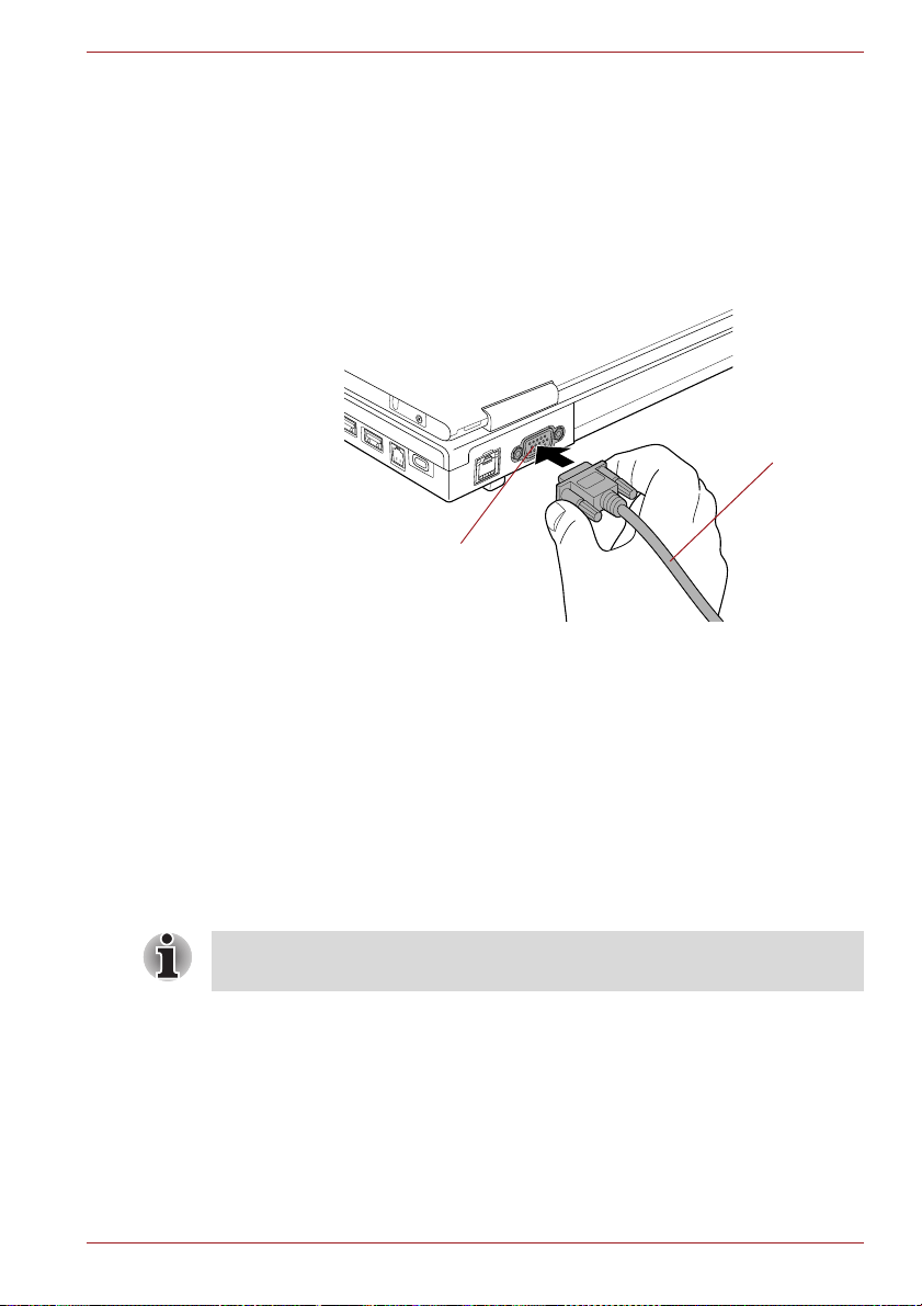
Hardware, Utilities and Options
External monitor
An external analog monitor can be connected to the external monitor port
on the computer. To connect a monitor, follow the steps as detailed below:
Connecting the monitor cable
1. Turn the computer's power off.
2. Connect the monitor cable to the external monitor port and tighten the
screws on the left and right hand side of the connector as required.
External monitor port
Figure 3-14 Connecting the monitor cable to the external monitor port
3. Turn the external monitor's power on.
4. Turn the computer's power on.
When you turn on the power, the computer will automatically recognize the
monitor and determine whether it is a color or monochrome device. In the
event that you find that there are issues getting an image displayed on the
correct monitor, you should consider using the FN + F5 hot key to change
the display settings (if you then disconnect the external monitor before you
turn the computer's power off, be sure to press FN + F5 hot key again to
switch to the internal display).
Please refer to Chapter 5, The Keyboard, for further details on using hot
keys to change the display setting.
Monitor cable
Do not disconnect the external monitor while in Sleep or Hibernation Mode.
Turn off the computer before disconnecting the external monitor.
When displaying desktop at external analog monitor, desktop is sometimes
displayed on the center of the monitor with black bars around desktop (with
small size).
At that time, please read the manual of the monitor and set the display
mode which is supporting at the monitor. Then it will be displayed with
suitable size with correct aspect ratio.
User’s Manual 3-31

Hardware, Utilities and Options
USB FDD Kit
The USB floppy diskette drive accommodates either a 1.44MB or 720KB
floppy diskette and connects to one of the computer's USB ports.
USB connector
Disk-In-Use
Indicator
Floppy
diskette slot
Eject button
Figure 3-15 The USB floppy diskette drive
Connecting the USB floppy diskette drive
To connect the drive, plug the floppy diskette drive’s USB connector into a
computer’s USB port.
Make sure the connector is properly aligned with the socket. Do not try to
force the connection, doing so can damage the connecting pins.
USB port
USB connector
Figure 3-16 Connecting the USB floppy diskette drive
If you connect the USB floppy diskette drive after the computer has already
been turned on, it will take about ten seconds for it to be recognized by the
computer. Do not attempt to disconnect and reconnect the drive before this
period has elapsed.
User’s Manual 3-32

Hardware, Utilities and Options
Disconnecting the USB floppy diskette drive
When you have finished using the USB floppy diskette drive, you can follow
the procedures below in order to disconnect it:
1. Wait for the Disk-In-Use Indicator light to go out to make sure all floppy
diskette activity has stopped.
If you disconnect the USB floppy diskette drive or turn off the power while
the computer is accessing the drive you may lose data or damage the
floppy diskette or the drive.
2. Click the Safely Remove Hardware icon on the Windows Taskbar.
3. Click the USB floppy diskette drive device that you want to remove.
4. Carefully pull the floppy diskette drive's USB connector out from within
the computer's USB port.
eSATA (External Serial ATA)
An device corresponding to eSATA function can be connected to the
eSATA/USB combo port on the computer.
Connecting the eSATA device
To connect an eSATA device, follow the steps as detailed below:
1. Connect an eSATA cable to the eSATA/USB combo port.
Make sure the connector is properly aligned with the socket.
Do not try to force the connection, doing so can damage the connecting
pins.
eSATA/USB
combo port
eSATA cable
Figure 3-17 Connecting an eSATA cable to the eSATA/USB combo port
User’s Manual 3-33
Hardware, Utilities and Options
■ A connected eSATA device may not be recognized if it is connected to
the computer's eSATA/USB combo port while the computer is in Sleep
Mode or Hibernation Mode. If this occurs, disconnect the eSATA device
and then reconnect the device while the computer is turned on.
■ If you connect an eSATA device after the computer has already been
turned on, it will take about ten seconds for it to be recognized by the
computer.
Do not attempt to disconnect and reconnect the drive before this period
has elapsed.
Disconnecting an eSATA device
When you have finished using an eSATA device, you can follow the
procedures below in order to disconnect it:
1. Wait for the indicator light of an eSATA device to go out to make sure all
activity has stopped.
If you disconnect an eSATA device or turn off the power while the
computer is accessing the drive you may lose data or damage an eSATA
device or the drive.
2. Click the Safely Remove Hardware icon on the Windows Taskbar.
3. Click an eSATA device that you want to remove.
4. Carefully pull an eSATA device's eSATA/USB combo connector out
from within the computer's eSATA/USB combo port.
i.LINK (IEEE1394)
i.LINK (IEEE1394) is used for high-speed data transfer for a range of
compatible devices such as:
■ Digital video cameras
■ Hard disk drives
■ MO drives
■ Writable optical disc drives
Some models are equipped with a i.LINK (IEEE1394) port.
i.LINK uses a four-pin connector, which does not carry any electric current.
External devices will need their own power supply to operate.
Precautions
■ Make a back-up of your data before transferring it to the computer.
There is a possibility that the original data will be damaged. There is a
particular risk that some frames will be deleted in the case of digital
video transfer. TOSHIBA assumes no liability for such loss of data.
■ Do not transfer data in areas where static electricity is easily generated
or in areas subjected to electronic noise. Data can be destroyed.
User’s Manual 3-34

Hardware, Utilities and Options
■ If you are transferring data through an IEEE1394 hub, do not connect or
disconnect other devices from the hub during data transfer. There is a
likelihood that data will be damaged. Connect all devices to the hub
before you turn on the computer’s power.
■ You may not use any copyrighted video or music data copied from a
video camera except for your personal enjoyment.
■ If you connect/disconnect an i.LINK device to/from another i.LINK
device that is currently exchanging data with the computer, data frames
might be dropped.
■ Make sure data transfer has ended or turn off the computer, before you:
■ Connect/disconnect an i.LINK device to/from the computer.
■ Connect/disconnect an i.LINK device to/from another i.LINK device
that is connected to the computer.
Connecting the i.LINK (IEEE1394) cable
To connect the i.LINK (IEEE1394) cable, follow the steps as detailed below:
1. Make sure the connectors are properly aligned and plug the i.LINK
(IEEE1394) cable into the computer.
i.LINK (IEEE1394)
port
i.LINK (IEEE1394)
connector
Figure 3-18 Connecting the i.LINK (IEEE1394) cable into the computer
2. Plug the other end of the cable into the device.
Note the following when you use i.LINK:
■ You may need to install drivers for your i.LINK devices.
■ Not all i.LINK devices have been tested. Therefore, compatibility with all
i.LINK devices cannot be guaranteed.
■ Some devices might not support sleep or automatic off functions.
■ Do not connect or disconnect an i.LINK device while it is using an
application or when the computer is automatically shutting it down to
save power. Data might be destroyed.
User’s Manual 3-35

Hardware, Utilities and Options
Disconnecting the i.LINK (IEEE1394) cable
To disconnect the i.LINK (IEEE1394) cable, follow the steps as detailed
below:
1. Open the Safely Remove Hardware icon on the Windows Taskbar.
2. Point to i.LINK (IEEE1394) device and click.
3. Disconnect the cable from the computer then from the i.LINK device.
Refer also to the documentation that came with your i.LINK device.
Serial port
The serial connector can be used to connect to RS-232C compatible
devices.
RS-232C compatible devices include the following:
■ Modem
■ Mouse
■ Printer
Some models are equipped with a serial port.
To connect a serial port, follow the steps as detailed below:
1. Turn the computer’s power off.
2. Connect the serial connector to the serial port and tighten the screws on
the left and right hand side.
Serial connector
Serial port
Figure 3-19 Connecting the serial connector to the serial port
User’s Manual 3-36

Hardware, Utilities and Options
TOSHIBA Express Port Replicator
In addition to the ports available on the computer, the TOSHIBA Express
Port Replicator also provides several kinds of ports. The TOSHIBA Express
Port Replicator connects directly to the docking interface on the underside
of the computer. The AC adaptor connects the TOSHIBA Express Port
Replicator to a power source.
The computer must be configured properly before connecting to a LAN.
Logging onto a LAN using the computer’s default settings could cause a
malfunction in LAN operation. Check with your LAN administrator
regarding set-up procedures
■ You must connect the AC adaptor before you connect to a TOSHIBA
Express Port Replicator.
■ When a TOSHIBA Express Port Replicator is connected to the
computer, you can not use the following computer’s ports: LAN jack,
DC IN 15V jack and External monitor port.
■ When connecting an AC Adaptor to the TOSHIBA Express Port
Replicator, use only the AC Adaptor included with TOSHIBA Express
Port Replicator. Do not use the computer’s AC Adaptor.
The following ports are available on the TOSHIBA Express Port Replicator.
■ RJ45 LAN jack
■ External monitor port
■ DC IN 15V jack
■ Security lock slot
■ Universal Serial Bus 2.0 port (four)
■ DVI port
.
■ As the port operation of all DVI (Digital Visual Interface) monitors has
not been confirmed, some DVI monitors may not function properly.
■ Set the TOSHIBA Express Port Replicator's Slide Adjuster to SLIDE
position #3 or #5 when connecting this computer to the TOSHIBA
Express Port Replicator. Refer to the TOSHIBA Express Port
Replicator User's Manual for more details on connection methods.
User’s Manual 3-37

Hardware, Utilities and Options
Security lock
A security locks enable you to anchor your computer a desk or other heavy
object in order to help prevent unauthorized removal or theft. The computer
has a security lock slot on its right side into which you can attach one end of
the security cable, while the other end attaches to a desk or similar object.
The methods used for attaching security cables differ from product to
product. Please refer to the instructions for the product you are using for
more information.
Connecting the security lock
In order to connect a security cable to the computer, follow the steps as
detailed below:
1. Turn the computer so its right hand side faces you.
2. Align the security cable with the lock slot and secure it in place.
Security lock slot
Figure 3-20 Security lock
User’s Manual 3-38

Optional accessories
You are able to add a number of options and accessories in order to make
your computer even more powerful and convenient to use. For reference,
the following list details some of the items that are available from your
reseller or TOSHIBA dealer:
Hardware, Utilities and Options
DDR2-667 Memory
Kit
DDR2-800 Memory
Kit
Universal AC
Adaptor
Battery Pack An additional battery pack can be purchased for
High Capacity
Battery Pack
Extended Capacity
Battery Pack
Battery Charger The optional battery charger allows you to
USB FDD Kit The USB floppy diskette drive accommodates
A 512MB, 1,024MB or 2,048MB memory module
(DDR2-667) can easily be installed in the
computer.
A 1,024MB, 2,048MB or 4,096MB memory
module (DDR2-800) can easily be installed in the
computer.
If you frequently use your computer at more than
one site, it may be convenient to purchase an
additional AC adaptor to be kept at each site in
order to remove the need to always carry the
adaptor with you.
use as either a spare or replacement. Please
refer to Chapter 6, Power and Power-Up Modes
for further information.
An additional battery pack can be purchased for
use as either a spare or replacement.
An additional battery pack can be purchased for
use as either a spare or replacement.
charge extra battery packs outside of having to
use the computer.
either a 1.44MB or 720KB floppy diskette through
connection to one of the computer's USB ports.
In use, please be aware that, while you cannot
format 720KB floppy diskettes under Windows 7,
you are able to read and write to diskettes that
have already been formatted.
TOSHIBA Express
Port Replicator
User’s Manual 3-39
The TOSHIBA Express Port Replicator provides
the ports available on the computer in addition to
a digital visual interface (DVI) port, External
monitor port, four Universal Serial Bus ports
(USB 2.0) and a LAN jack.
 Loading...