

Page 1

FILE NO : A09-01P
Quick reference
AIR TO WATER HEAT PUMP
Page 2
Quick Reference Guide - Page 2
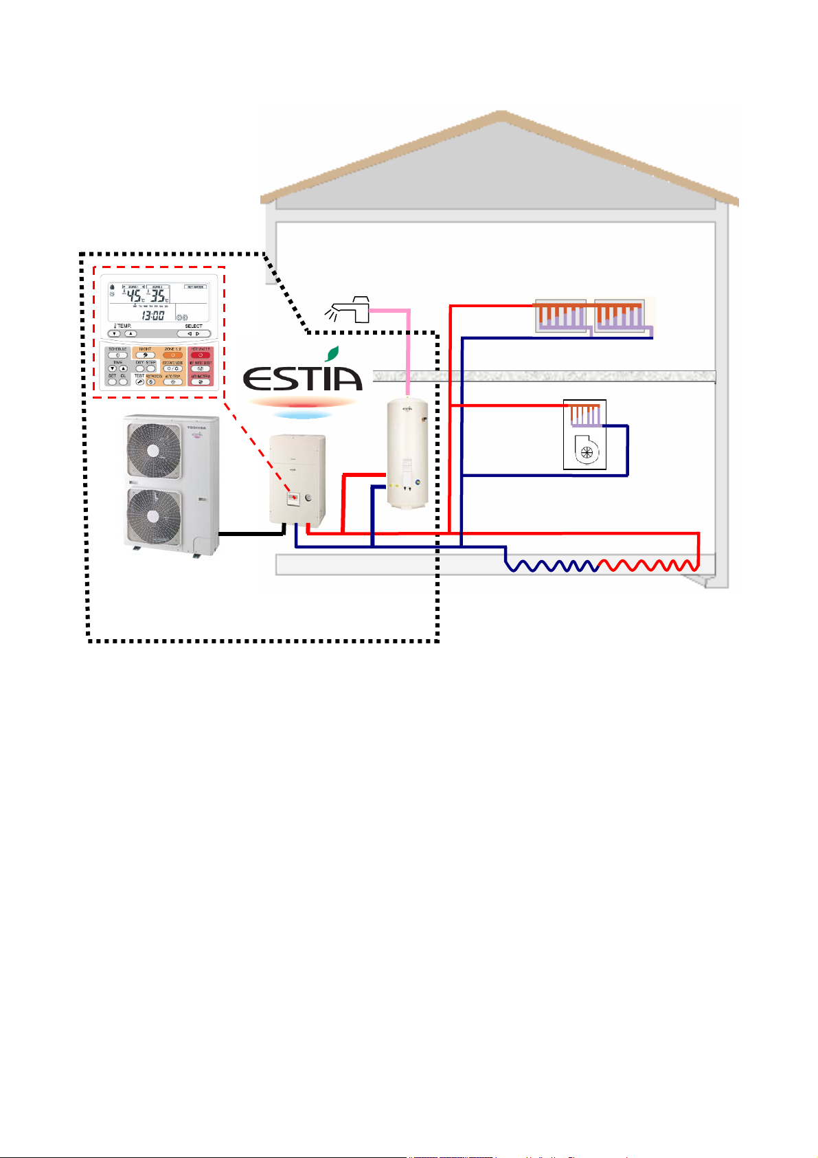
Estia System
Estia Outdoor Unit
HWS-802H-E 8.0kW Inverter (use Hydro Unit: HWS-802XWH**-E)
HWS-1102H-E 11.2kW Inverter (use Hydro Unit: HWS-1402XWH**-E)
HWS-1402H-E 14.0kW Inverter (use Hydro Unit: HWS-1402XWH**-E)
Estia Hydro Unit
HWS-802XWHM3-E Plate Heat exchanger and 3kW Backup Heater
HWS-802XWHT6-E Plate Heat exchanger and 6kW Backup Heater
HWS-1402XWHM3-E Plate Heat exchanger and 3kW Backup Heater
HWS-1402XWHT6-E Plate Heat exchanger and 6kW Backup Heater
HWS-1402XWHT9-E Plate Heat exchanger and 9kW Backup Heater
Estia Hot Water Cylinder (EU)
HWS-1501CSHM3-E 150L Stainless Steel Tank (with EU Accessories)
HWS-2101CSHM3-E 210L Stainless Steel Tank (with EU Accessories)
HWS-3001CSHM3-E 300L Stainless Steel Tank (with EU Accessories)
Estia Hot Water Cylinder (UK)
HWS-1501CSHM3-UK 150L Stainless Steel Tank (with UK Accessories)
HWS-2101CSHM3-UK 210L Stainless Steel Tank (with UK Accessories)
HWS-3001CSHM3-UK 300L Stainless Steel Tank (with UK Accessories)
Note:
Under floor heating, Fan Coil units, Radiators, valves and Hot Water Piping are procured locally.
Outdoor unit
Hydro unit
Domestic Hot Water
Hot water
cylinder
Space Conditioning
Radiator
Fan coil unit
(Heating or Cooling)
Under floor heating
(Zone Control)
Page 3

Quick Reference Guide - Page 3
Notes on System Design
• The input water temperature to the Hydro Unit must be 55°C or less.
Especially, be careful when there is an external heating source such as a boiler.
When hot water over 55°C returns, it may result in a failure of the unit or water leakage.
• The flow rate of the circulating water must meet the following range:-
11 and 14 kW 17.5 L/minute or more
8 kW 13 L/minute or more
If the flow rate becomes less than the minimum, the protective device is activated to stop operation.
Ensure the flow rate with a bypass valve, etc. when you use a flow rate valve for the Hydro Unit.
• Do not drive water by power other than the pump built in the Hydro Unit.
• The backup heater operates supplementary to exert a prescribed capacity when the heat pump
cannot exert its capacity at a low outside temperature.
• Install the Hydro Unit and water pipes in a place in which they do not freeze.
• Make the water circuit closed. Never use it as an open circuit.
• To prevent damage to the system during outdoor defrost the circulating water must be 20 litres
or more. If total water amount is not enough, the unit may not function fully due to protective
operation.
Options required for each function
Purpose
Space Heating - -
Space Heating &
Space Cooling
(All Rooms)
Space Heating &
Space Cooling
(partly heating only)
150L Hot water cylinder HWS-1501CSHM3-E
150L Hot water cylinder HWS-1501CSHM3-UK
Domestic Hot Water
2-zone control - -
Interlocking with
boiler
Interlocking with
booster heater
210L Hot water cylinder HWS-2101CSHM3-E
210L Hot water cylinder HWS-2101CSHM3-UK
300L Hot water cylinder HWS-3001CSHM3-E
300L Hot water cylinder HWS-3001CSHM3-UK
Output control board kit
Part name Model code Part name
(1)
Toshiba Supply Procure locally
- - Fan coil(s) only
- -
- - Electric heater
Radiator(s),
Fan coil(s),
Under floor heating
Fan coil(s) plus
Radiator(s)
or Under floor heating
Motorized 2-way
valve
Motorized 3-way
valve
Earth leakage breaker
Motorized mixing
valve
Circulator pump
Buffer tank
TBC-PCIN3E Boiler
Page 4
Quick Reference Guide - Page 4
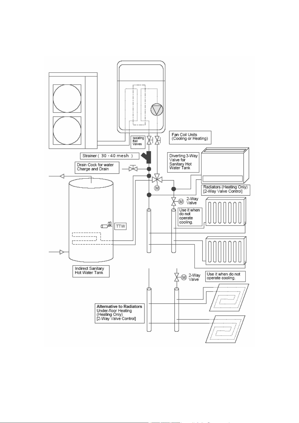
Installation Examples
Space Cooling and Space Heating with Domestic Hot Water
When both cooling and heating are used, install a 2-way valve (for cooling) to the pipe to the room
for heating only.
Page 5
Quick Reference Guide - Page 5
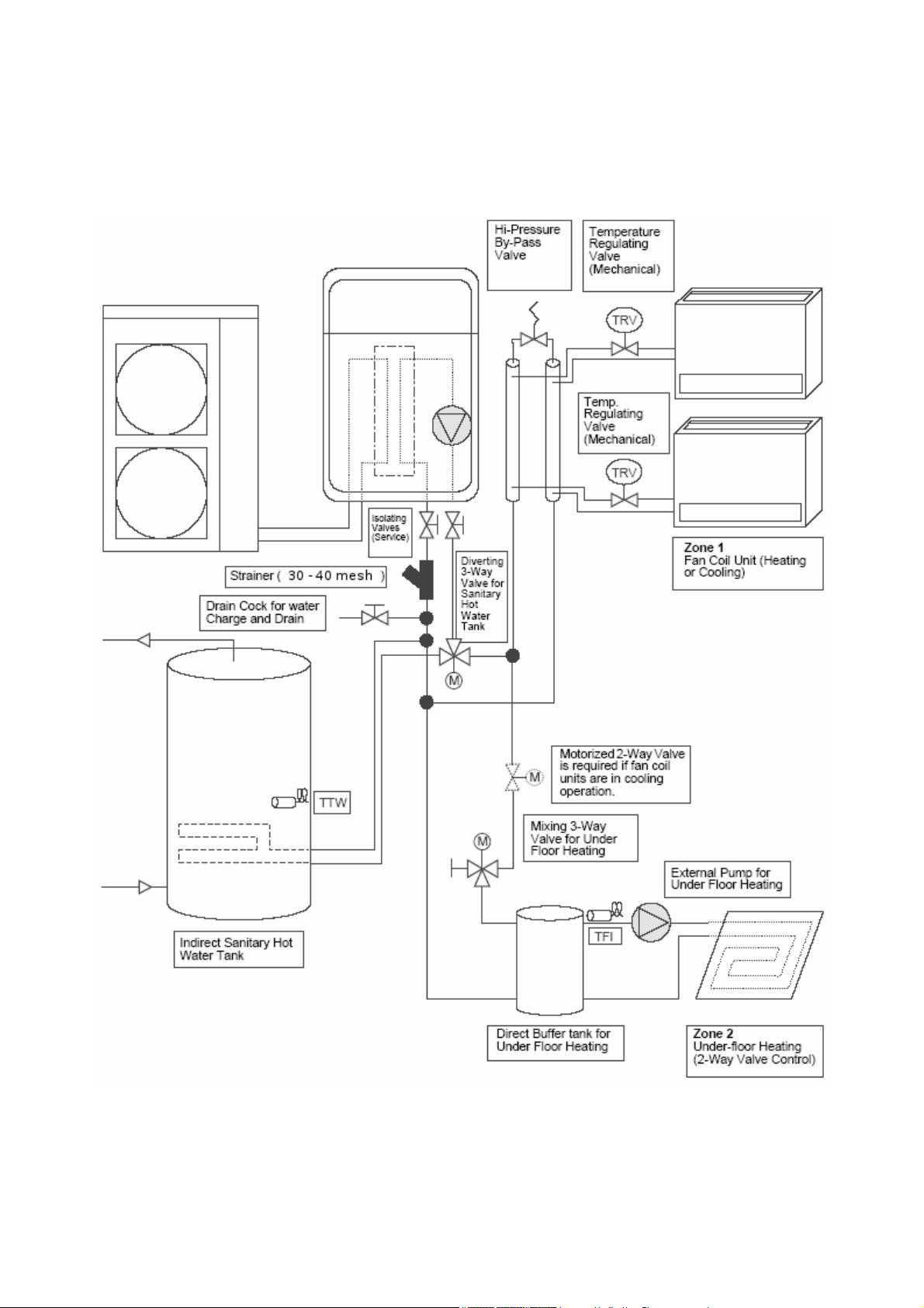
Installation Examples (cont.)
2-Zone Space Heating with Domestic Hot Water
The following shows an example of the 2-zone temperature control.
A buffer tank and a water pump are required for the 2-zone temperature control. This example is
Heating only, if the Fan Coils are to be used for Cooling then a 2-Way valve must be fitted.
Page 6
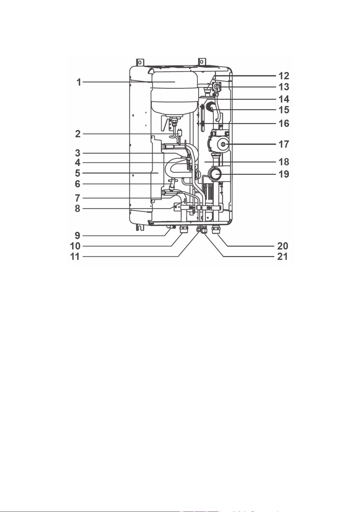
Hydro Unit – Exploded View
Quick Reference Guide - Page 6
1 : Expansion vessel
2 : Hi pressure switch (4.15 MPa)
3 : Temperature sensor (for Heat pump outlet -TWO)
4 : Pressure sensor
5 : Heat exchanger
6 : Flow switch (13.0 L/min 17.5 L/min)
7 : Temperature sensor (for refrigerant -TC)
8 : Temperature sensor (for water inlet -TWI)
9 : Drain nipple
10 : Water inlet connection
11 : Refrigerant liquid connection
12 : Air relief valve
13 : Pressure relief valve (0.3 MPa (3 bar))
14 : Thermal protector (auto)
15 : Temperature sensor (for water outlet THO)
16 : Thermal protector (Single operation)
17 : Water pump
18 : Backup heater (3 kW, 3 kW x 2, 3 kW x 3)
19 : Manometer
20 : Water outlet connection
21 : Refrigerant gas connection
Page 7
Quick Reference Guide - Page 7
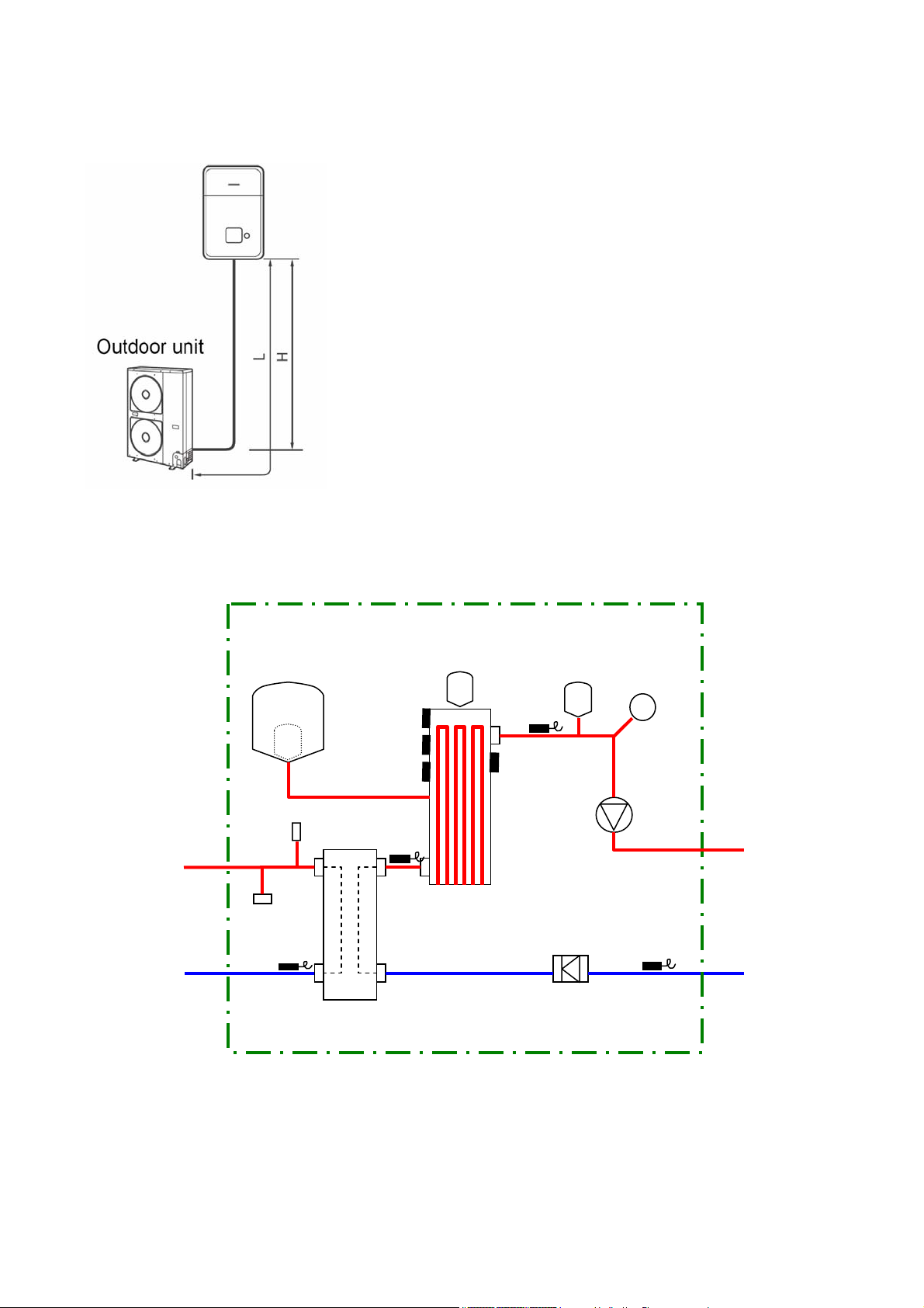
Refrigerant Piping
Refrigerant Pipe Lengths and Height
The length and height of the refrigeration pipe must be within the following values.
Minimum Pipe Length
HWS-802H-E : 5 m
HWS-1102H-E : 3 m
HWS-1402H-E : 3 m
Maximum Pipe Length and Height
H: Max. ±30 m (above or below)
L: Max. 30 m
Note
The maximum pipe length cannot be increased using additional
refrigerant.
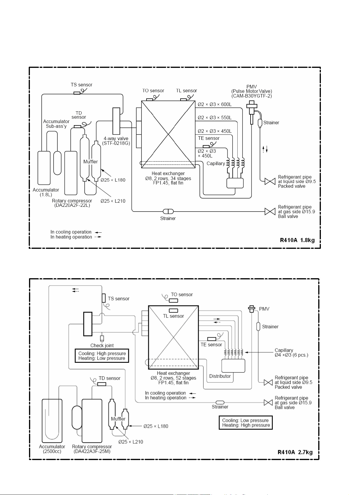
Refrigeration and Water Cycle Diagrams
Hydro Unit
Refrigerant pipe
at gas side
(Outer ø15.88)
Refrigerant pipe
at liquid side
(Outer ø9.52)
Expansion vessel
Hi_P_Switch
P_Sensor
TC
Sensor
Water Heat exchanger
Thermal
Protector
TWO
Sensor
Air vent valve
Backup heater
Pressure
relief
valve
THO
Sensor
Flow_Switch
Pressure
Gauge
Pump
Water Out
(1 1/4")
TWI
Sensor
Water IN
(1 1/4")
Page 8
Outdoor Unit
HWS-802H-E
Quick Reference Guide - Page 8
HWS-1102H-E, 1402H-E
Page 9
Quick Reference Guide - Page 9
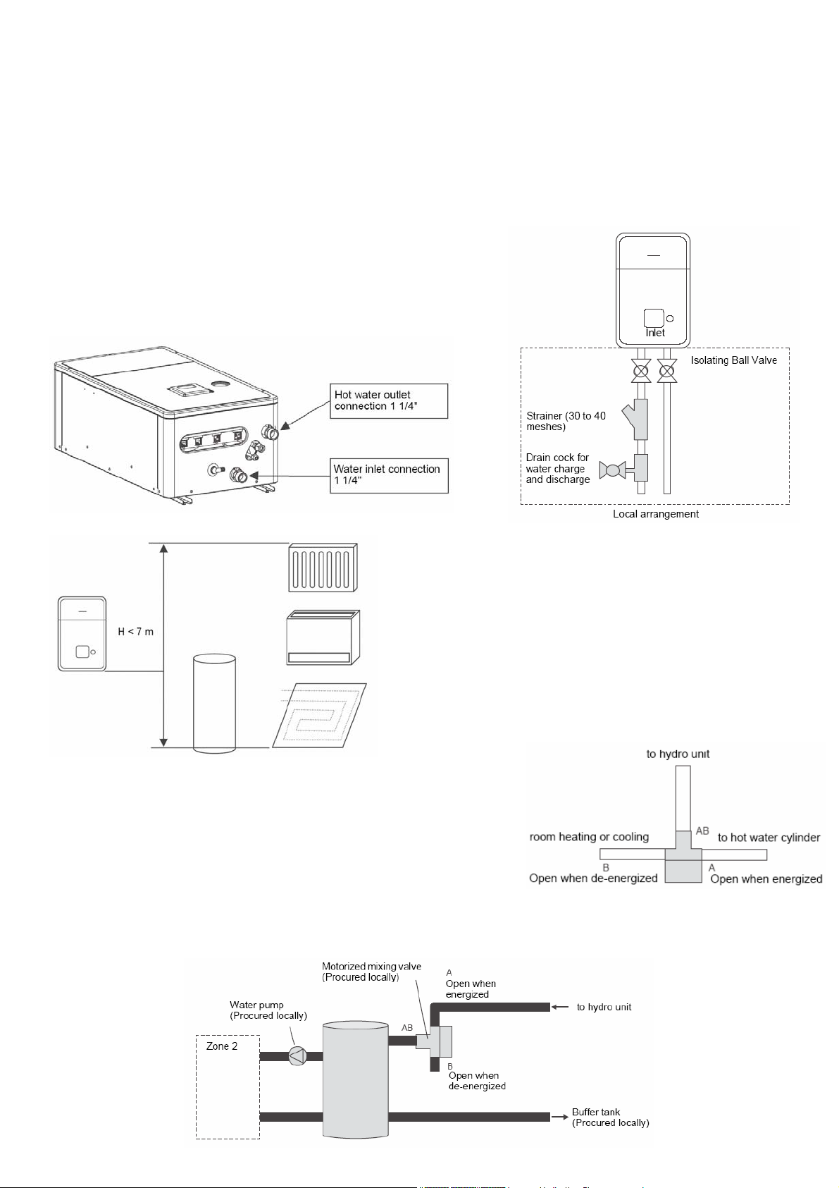
Water Piping
• Install water pipes according to the regulations of respective countries.
• Install water pipes in a freeze-free place.
• Make sure that water pipes have sufficient pressure resistance (The setting value of the pressure
relief valve is 0.3 MPa).
• Do not use zinc plated water pipes. When steel pipes are used, insulate both ends of the pipes.
Water Connections
• Install a strainer with 30 to 40 meshes (procure locally) at
the water inlet of the Hydro Unit.
• Install drain cocks (procure locally) for water charge and
discharge at the lower part of the Hydro Unit.
Water Piping Limitations
Design the water pipe length within the QH
characteristics of the pump (flow-rate and pump
head).
The maximum height difference for the water pipes i
7 metres.
Piping to hot water tank (option
Water supplied to the hot water cylinder is branched by a
motorized 3-way valve (procured locally).
Connect the hot water cylinder to port A (open when
energized) of the valve.
)
Piping to 2-zone operation (option)
To perform 2-zone temperature control circulate water using another pump (procured locally)
through a motorized mixing valve (procured locally) and a buffer tank (procured locally).
s
Page 10
Quick Reference Guide - Page 10
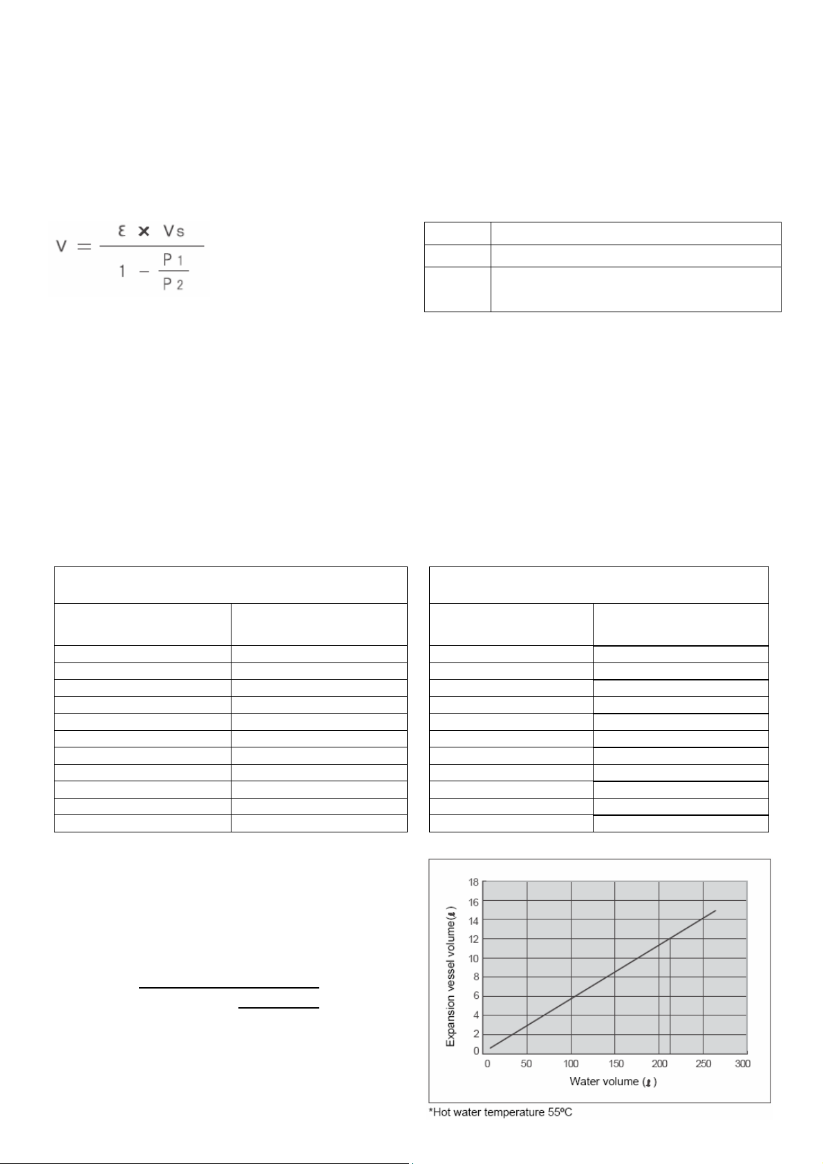
Checking water volume and initial pressure of expansion vessel
The expansion vessel of the Hydro Unit has a capacity of 12 litres.
The initial pressure of the expansion vessel is 0.1 MPa (1 bar).
The suggested initial water charge is 0.2MPa (2 bar).
The pressure of the safety valve is 0.3 MPa (3 bar).
Verify whether the capacity of the expansion vessel is sufficient using the following expression. If
the volume is insufficient, install an appropriate external expansion vessel.
V Action
< 12 L Internal Expansion Vessel Size OK
> 12 L
Internal Expansion Vessel Size too small.
Install appropriate external expansion vessel
V: Necessary total vessel capacity (L)
Ɛ: Water expansion coefficient at average hot water temperature
Vs: Total water volume in the closed system (Do not include Hot Water Cylinder)
P1: System pressure at tank setting position (Mpa_abs*).
(Pipe inner pressure during pump operation before heating device operates = water supply
pressure)
P2: Maximum pressure used during operation at tank setting position (MPa_abs*).
(= safety valve setting pressure)
* The absolute pressure value (abs.) is obtained by adding the atmospheric pressure (0.1 MPa (1
bar)) to the gauge pressure.
Water temperature and expansion coefficient (Ɛ)
Hot water temperature
(°C)
0 0.0002 50 0.0121
4 0.0000 55 0.0145
5 0.0000 60 0.0171
10 0.0003 65 0.0198
15 0.0008 70 0.0229
20 0.0017 75 0.0258
25 0.0029 80 0.0292
30 0.0043 85 0.0324
35 0.0050 90 0.0961
40 0.0078 95 0.0967
45 0.0100 - -
Expansion rate
(Ɛ)
Water temperature and expansion coefficient (Ɛ)
Hot water temperature
(°C)
Expansion rate
(Ɛ)
Example
Maximum Hot Water temperature: 55°C, initial
water charge: 0.2MPa and system volume: 200 L.
The calculated Vessel capacity (V) is 11.6 L:-
11.6
=
0.0145
1
x
-
In this case V < 12 L therefore the internal
expansion vessel is sufficient.
There is no need to install an external expansion
vessel.
200
(0.2+0.1)
(0.3+0.1)
Page 11

Quick Reference Guide - Page 11
Pump operation / configuration
Change Pump speed, so that water flow is always greater than the minimum flow rate. If water flow
is lower than the minimum rate during operation, the unit detects error.
Water charging
Charge water until the pressure gauge shows 0.2 MPa (2 bar).
Hydraulic pressure may drop when the trial run begins. In that case, add water.
Air may enter if the charged hydraulic pressure is low.
Loosen the purge valve cap by two turns to release air.
Loosen the cap of the pressure relief valve to release air.
Water may come out of the pressure relief valve.
Release the air completely from the water circuit. Failure to do so
may disable correct operation.
Water quality
The water used must satisfy EN directive 98/83 EC.
Piping insulation
It is recommended that insulation treatment be applied to all pipes. To perform optional cooling
operation, apply insulation treatment of 20 t or more to all pipes.
Page 12

Electrical Connections
E Box layout
Quick Reference Guide - Page 12
Terminal Block Connections
Page 13

Power Lines Schematic
Quick Reference Guide - Page 13
Control Lines Schematic
Page 14

Electrical supply / cable specifications
Wiring specifications (power line)
Quick Reference Guide - Page 14
Description
POWER
SUPPLY
Maximum
current
Installation
fuse rating
Cable size
14 kW 230 V ~ 50 Hz 22.8 A 25 A 2.5 mm² or more
Outdoor unit power
11 kW 230 V ~ 50 Hz 22.8 A 25 A 2.5 mm² or more
8 kW 230 V ~ 50 Hz 20.8 A 25 A 2.5 mm² or more
Outdoor-Hydro – – 1.5 mm² or more
3 kW 230 V ~ 50 Hz 13 A 16 A 1.5 mm² or more
Hydro inlet heater
power
6 kW 400 V 3N ~ 50 Hz 15 A (13 A x 2P) 25 A 2.5 mm² or more
9 kW 400 V 3N ~ 50 Hz 23 A (13 A x 3P) 25 A 2.5 mm² or more
Hydro cylinder heater power 230 V ~ 50 Hz 12 A 16 A 1.5 mm² or more
Hydro - cylinder – 12 A – 1.5 mm² or more
Wiring specification (control line)
Description
Line spec
Maximum
current
3-way valve control 2 line or 3 line 100 mA 12 m 0.75 mm² or more
Mixing valve control 3 line 100 mA 12 m 0.75 mm² or more
2-zone thermo sensor 2 line 100 mA 5 m 0.75 mm² or more
Cylinder thermo sensor
2+GND (shield
wire)
100 mA 5 m 0.75 mm² or more
Second remote controller 2 line 50 mA 50 m 0.75 mm² or more
Maximum
length
Cable Size
Control parts specifications
Maximum
Description Power
current
Type
Connection
destination
L
, N
1
, 2 , 3
L
, N (TB02)
L1
, L2 , L3
N
(TB02)
L
1
TB03)
, N (
, 2 (TB03)
Connection
destination
7
, 8 , 9
(TB05)
1
, 2 , 3
or
2
, 3 , 4
(TB04)
C
, D (TB06)
A
, B (TB06)
1
, 2 (TB07)
Motorized 3-way valve (for
hot water)
Motorized 2-way valve (for
cooling)
Motorized mixing valve type
1 (for 2-zone)
AC 230 V 100 mA
AC 230 V 100 mA spring return type (normally open )
AC 230 V 100 mA
Spring return type Note: 3-wire SPST and SPDT type can be
used by changing the function code.
60 sec 90º. SPDT type Note: SPST and 20 to 240 sec type
can be used by changing the function code.
Output line specifications
Description
Output
Maximum
current
External pump No. 1 AC230V 1 A – 12 m
External booster heater AC230V 1 A – 12 m
Boiler control
ALARM Output
Operation Output
Defrost Output
Nonvoltage
contacts
Nonvoltage
contacts
Nonvoltage
contacts
Nonvoltage
contacts
0.5 A AC230 V 12 m
1 A DC24 V 12 m
0.5 A AC230 V 12 m
1 A DC24 V 12 m
0.5 A AC230 V 12 m
1 A DC24 V 12 m
0.5 A AC230 V 12 m
1 A DC24 V 12 m
Max
voltage
Maximum
length
Interlocked with the Hydro Unit
pump
Output as required when outdoor
air temperature is -20°C or less
Output as required when outdoor
air temperature is -10°C or less
Page 15

Quick Reference Guide - Page 15
Input line specifications
Description
Emergency stop control Non-voltage 12 m
Cylinder thermostat input Non-voltage 12 m
Cooling thermostat input Non-voltage 12 m
Heating thermostat input Non-voltage 12 m
Input
Maximum length
CAUTION
Earthing arrangements
The Hydro Unit and related equipment must be earthed in accordance with your local and national
electrical regulations.
It is essential that the equipment is earthed to prevent the electric shock and damage to the
equipment.
Electrical connection to hydro unit
• Remove the front cover and the electrical box cover from the Hydro Unit.
• The Hydro Unit power cable must be sized in accordance with refer to “Electrical supply/cable
specifications”.
• Connect the Hydro Unit power cable to Terminal 02 as shown below.
Single Phase Units: Live conductor – Terminal L1
Neutral conductor – Terminal L2
Earth conductor – Earth terminal
Three Phase Units: Phase 1 conductor – Terminal L1
Phase 2 conductor – Terminal L2
Phase 3 conductor – Terminal L3
Neutral conductor – Terminal N
Earth conductor – Earth
• Ensure the Hydro Unit power cable is secured using the cable clamp fitted in the electrical box.
• Ensure the Hydro Unit power cable connection terminals are tight.
Outdoor unit to hydro unit electrical connection
• Ensure electrical circuits are isolated before commencing work.
• The Outdoor Unit to Hydro Unit interconnecting cable must be sized in accordance with refer to
“Electrical supply/cable specifications”.
• Connect the Outdoor Unit to Hydro Unit interconnecting cable as shown in the diagram above.
• Ensure the Outdoor Unit to Hydro Unit interconnecting cable is secured using the cable clamp
fitted in the electrical box.
• Ensure the Outdoor Unit to Hydro Unit interconnecting cable connection terminals are tight.
Page 16

Quick Reference Guide - Page 16
Electrical connection for external booster heater
CAUTION
The maximum current available from the booster heater output is 1 A. Do not connect the
booster heater directly to Terminal Block 05 on the Hydro Unit. The AC230 V 1 A output
from the Hydro Unit must only be used to energize an external contactor (Supplied locally).
• The booster heater can be installed only for room heating and cannot be used for hot water
supply.
• Install the booster heater downstream of the 3-way valve on the indoor unit side.
• The booster heater is an external heater, supplied locally, used to assist the Hydro Unit during
low ambient conditions.
• The output from the Hydro Unit is only enabled when the outdoor air temperature is less than -
20°C.
• Ensure the external booster heater is installed and set up in accordance with all Local, National
and International regulations.
• Connect the coil, of the field supplied contactor, to terminals 5 & 6 on Terminal Block 05. The
contactor will energize in the event of low ambient conditions.
• A separate dedicated electrical supply must be used for the external booster heater. This must
be connected through the contacts on the field supplied contactor (see diagram below):-
Electrical connection for external additional pump (P2)
CAUTION
The maximum current available from the additional pump output is 1 A. Do not connect the
additional pump directly to Terminal Block 05 on the Hydro Unit. The AC230 V 1 A output
from the Hydro Unit must only be used to energize an external contactor (Supplied locally).
• The Hydro Unit has the facility to connect an additional circulating pump, if required, into the
heating or cooling system.
• Install the external pump so that its motive power does not affect the internal pump.
• The output for the pump is synchronized with the operation of the main circulating pump (P1)
inside the Hydro Unit.
• Connect the coil, of the field supply contactor, to terminals 1 & 2 on Terminal Block 05.
• A separate dedicated electrical supply must be used for the additional pump. This must be
connected through the contacts on the field supplied contactor (see diagram below):-
Page 17

Quick Reference Guide - Page 17
2-way valve (for cooling) connection
Required Valve Specification:
Electrical Specification: 230 V; 50 Hz; <100 mA
Return Mechanism: 2-wire spring return.
• The Hydro Unit has the facility to connect a 2-way valve to
isolate Space Conditioning Units that do not perform cooling,
when Cooling Mode is selected.
• Connect the 2-way valve in accordance with the diagram
(opposite):-
3-way valve (diverter) connection
Required Valve Specification:
Electrical Specification: 230 V; 50 Hz; <100 mA
Valve Diameters: Port A, Port B: Ø 1 1/4"
Return Mechanism: 3 types of 3-way valve (diverter) can be used.
Set the 3-way valve in use with the DIP switch SW13-1 on the Hydro Unit board.
Diverter Valve Description
Type 1 2-wire spring return OFF
Type 2 3-wire SPST OFF
Type 3 3-wire SPDT ON
Continuous operation of the valve motor at the fully open position is not recommended.
• The 3-way diverter valve is used to select either domestic hot water or space heating.
• Connect the 3-way diverter valve in accordance with the diagram below:-
SW13-1
Page 18

Quick Reference Guide - Page 18
3-way mixing valve connection
Required Actuator Specification
Electrical Specification:230 V; 50 Hz; <100 mA
The 3-way mixing valve is used to achieve the temperature differential needed in a 2-zone heating
system.
• Connect the 3-way mixing valve in accordance with the diagrams below:-
Hot water cylinder connection (optional)
• Please refer to “Electrical supply/cable specifications” for fuse/cable size and for
connection details.
Electrical Connection (Hot Water Cylinder Electric Heater)
• The electric heater, incorporated in the hot water cylinder, requires a separate supply to Hydro
Unit.
• Connect the hot water cylinder heater electrical supply in accordance with shown below:
Live conductor: Terminal L on Terminal Block 03
Neutral conductor: Terminal N on Terminal Block 03
Earth Conductor: Earth terminal on Terminal Block 03
• Connect the hot water cylinder heater to the Hydro Unit as shown below:
Live conductor to hot water cylinder: Terminal 1 on Terminal Block 03
Neutral conductor to hot water cylinder: Terminal 2 on Terminal Block 03
Earth conductor to hot water cylinder: Earth terminal on Terminal Block 03
Electrical Connection (Hot Water Cylinder temperature Sensor)
• Connect the hot water cylinder temperature sensor as shown below to terminals A & B on
Terminal Block 06 in the Hydro Unit.
• Please ensure that the interconnecting cable, between the Hydro Unit and the hot water cylinder,
is connected to earth at both ends of the cable using the shield wire.
Page 19

Setting DIP Switches on the Board
in the Hydro Unit
• Detach the front cover and the electric parts box cover of
the Hydro Unit.
• Set the DIP switches on the main board.
Quick Reference Guide - Page 19
SW10 Description
1
3 External P2 pump operation Continuous operation OFF ON
SW11 Description
1
2
3 Booster heater operation Operate
SW12 Description
1 Hot water supply operation Valid
2 Zone 1 operation Valid
3 Zone 2 operation Invalid
SW13 Description
1 Type of motorized 3-way valve
2 Interlocking with boiler Invalid
3 Auto restart for power failure Auto restart
SW02 Description
4 Room thermostat Invalid
Internal pump P1 operating
mode
Internal backup heater
operation
Hot water cylinder heater
operation
Continuous operation OFF ON HP synchronized
Operate
Operate
• 2-wire spring return type
• 3-wire SPST type
Default setting Alternate
Default setting Alternate
Default setting Alternate
Default setting Alternate
Default setting Alternate
Switch mode
Switch mode
OFF ON Not operate
OFF ON Not operate
OFF ON Not operate
Switch mode
OFF ON Invalid
OFF ON Invalid
OFF ON Valid
Switch mode
OFF ON 3-wire SPDT type
OFF ON Valid
OFF ON Manual restart
Switch mode
OFF ON Valid
Interlocked with the
internal pump
synchronized with P1.
Page 20

Hydro Unit Remote Control
Buttons and Functions
1. TEMP. button:
2. SCHEDULE
button:
3. TIME button:
4. SET button:
Changes the set temperature for
each operation mode (ZONE1/2 hot
water) by 1°C step.
Sets the current time and
scheduled weekly operation.
Changes time for current time
setting and scheduled weekly
operation setting with ▼ and ▲
buttons.
Determines the entered current
time setting and scheduled weekly
operation setting.
10. NIGHT button:
11. AUTO TEMP.
button:
12. OPERATE
MODE button:
13. ZONE1, 2
button:
Quick Reference Guide - Page 20
Controls the night set back
operation.
Switches setting temperature
automatically according to outside
temperature. (Pressing this button
long changes the mode to data
setting mode).
Selects ZONE1/2 operation mode
(heating or cooling).
Turns on/off the zone (floor
heating/radiator/FCU) operation.
5. CL button:
6. DAY button:
7. STEP button:
8. TEST button:
9. FROST
PROTECTION
button:
Clears settings for the current time
and scheduled weekly operation.
Sets days of the week for current
time setting and scheduled weekly
operation setting.
Specifies switching STEP number
in a day for weekly schedule.
Used for test run or service.
Controls minimum operation for
unused period (going out,
absence,etc.) for anti freezing.
14. ANTI BACTERIA
button:
15. HOT WATER
BOOST button:
16. HOT WATER
button:
17. SELECT button:
Regularly increases the hot water
temperature in the tank for
sterilization. (Pressing this button
long changes the mode to data
setting mode).
Boosts boiling when high tapping
temperature is required temporarily.
Turns on/off hot water operation.
Selects an operation mode when
changing the set temperature of
each operation mode.
NOTE
Some functions are not provided depending on the system specification in use.
Page 21

Display Explanation
Quick Reference Guide - Page 21
18: ZONE1, ZONE2
Display Description Display Description
Lights when floor heater or radiator
is connected (when the system has
floor heater or radiator).
ZONE1 selected for Temperature
to be changed.
Lights when system configured to
have 2 zones.
ZONE2 selected for Temperature
to be changed.
Lights during heating or cooling
operation using the heat pump.
Lights when the internal heater is
energized during heating
operation.
Lights when heating is selected.
20: HOT WATER
Lights when hot water supply system is
connected (when the system has hot
water supply).
HOT WATER selected for Temperature
Lights when hot water supply operation
Lights when the internal heater is
energized during hot water supply
Lights during hot water supply operation.
to be changed.
is performed by heat pump.
operation.
Lights while hot water boost is activated.
Lights when the ANTI BACTERIA button
is pressed and goes out when the button
is pressed again.
Lights when unit enters the data set
mode.
Displays hot water set temperature.
(40 to 80°C, factory setting: 65°C)
Lights when the set temperature or
sensor's water temperature is displayed
with the 7-segment indicator.
°C
Lights when cooling is selected.
Lights when the FROST
PROTECTION button is pressed
and goes out when the button is
pressed again.
Lights when Auto operation is
selected.
Displays heating/cooling set
temperature. (Heating: 20 to 55°C,
factory setting: Auto, cooling: 10 to
30°C) Goes out when Auto
operation is selected.
Lights when the set temperature or
sensor's water temperature is
displayed with the 7-segment
indicator.
°C
Page 22

Quick Reference Guide - Page 22
Display Explanation (cont.)
19: TIMER
Display Description Display Description
21: OPERATION
Clock: Displays the current time
(AM or PM).
Displays days of the week (Sunday
to Saturday).
Lights when the NIGHT button is
pressed and goes out when the
button is pressed again.
Lights when night time quiet
operation is set.
Indicates scheduled operation 1
status (including setting time).
Displays the scheduled operation
step when the scheduled operation
STEP1-5 program is set.
Lights during time setting and
scheduled operation setting.
Lights while internal pump (P1) or
external pump (P2) is driven.
Lights during backup operation only by
the heater.
Lights when the unit enters the data set
mode and goes out when the unit exits
the data set mode.
Lights when the unit enters the service
mode and goes out when the unit exits
the service mode.
Lights when an error occurs and goes
out when the error is cleared.
Lights for two seconds when settings are
completed.
Lights for two seconds when settings
failed.
Function Code Access
Set function codes for various operation modes, input using the remote controller.
There are 2 types of settings:-
1) Hydro Unit function code setting.
2) Remote controller function code setting.
Setting procedure for Hydro Unit function code
1. Press the TEST + SET + SELECT buttons
for four seconds or more to enter the hydro unit function code setting mode.
2. Set the function code number with the TEMP. buttons
(CODE No.: 01 to 91).
3. Set data (DATA) with the TIME buttons .
4. Press the SET button to confirm the settings.
5. The CL button is enabled only before the SET button is
pressed and the function code is changed.
6. Press the TEST button to finish the settings.
Setting procedure for Remote Controller function code
1. Press the TEST + CL TEMP. ▼ buttons for four seconds
or more to enter the ote controller function code setting mode.
2. Set the function code number with the TEMP. buttons
(CODE No.: 01 to 13).
3. Set data (DATA) with .
4. Press the SET button to determine the settings.
rem
the TIME buttons
+
5. The CL button is enabled only before the SET button is
pressed and the function code is changed.
6. Press the TEST button to end the settings.
Page 23

Quick Reference Guide - Page 23
Main setting items
) Setting Hot Water Temperature Range (functi on code 18 to 1F)
(1
• Set the temperature range for heating (zone 1, zone 2), cooling, and h
• The upper-limit and lower-limit temperatures of each mode can be set.
) Setting Heat Pump Operation Conditions for Hot Water Supply (func(2
• Set the heat pump start water temperature and heat pump stop water temperature.
is recommended that the default value be used.
3) Compensating Hot Water Temperature (fun(
• Compensate the target temperature from the remote controller set tempe
temperature lowers below the set outside air temperature.
4) Setting Hot Water Boost (function code 08 and 09) (
• Set the control time and target temperature when the HO
controller is pressed.
5) Setting Anti-Bacte(
• Set the control for the hot
• Set the target temperature, control period, start time (24-hour not nd target temperature retention
period.
this control setting according to regulations and rules of respective countries. • Make
6) Setting Priority Mode Temperature (
• Set the outside air temperature that change
• Hot Water - Heating Switching Temperature
• Boiler HP Switching Temperature
made.
7) Sett(
• Compensate the target temperature when Auto is set for temperature set
• The outside air temperature can be set to one of three points (T1, T2, and T3) within a range of -20 to 2
• The target temperature can be set to a value from 20 to 55°C.
• However, A > B > C > D > E.
ing Heating Auto Mode Temperature (function code 27 to 31)
ria
water cylinder when ANTI BACTERIA
t temperature, the HP operation stops and the external bWhen the temperature lowers the se
ction code 24 and 25)
T WATER BOOST
s the preferred operation mode.
temperature lowers the set tempeHeating operation takes precedence when the
ot water.
ation), a
tion code 20 and 21)
rt water tempe• The heat pump starts working when the water temperature lowers below the set sta
rature when the hot water
button on the remote
is set with the remote controller.
rature.
ting on the remote controller.
rature. It
oiler output is
0°C.
• The entire curve can be adjusted plus and minus 5°C by function code 27.
) Setting Frost Protection Temperature (function code 3A to 3B) (8
• Set the function when the FROST PROTECTION
• Set enabling/disabling of this function and the targe ater temperature.
• If disabling is set, the frost protection operation is not performed even wh
is pressed.
(9) Setting
• The increase/decrease time is used to set the response time.
10)Setting Night Setback (function code 26. remote control(
• Set the function when the NIGHT
• If disabling is set, the night setback operation is not performed even when the NIGHT
Frequency of Output to Internal Heater (function code 33 to 34)
button on the remote controller is pressed.
ion, re e. • Set enabling/disabling of this funct duction temperature, start time, and end tim
button on the remote controller is pressed.
t w
en the FROST PROTECTION
ler function code 0F to 11)
button is pressed.
button
Page 24

Quick Reference Guide - Page 24
Main setting item (cont.)
1)Setting 2-Way Valve (for Cooling) Operation (function code 3C)
(1
• When using both cooling and heating operations and there is an indoor
heating), install the 2-way valve and set this function code.
2)Setting 3-Way Valve Operation (function code 54)
(1
• This setting is not necessary for normal installation. Make
A and B of the 3-way valve are wrongly attached and it cannot be rectified on site.
(1
3)Mixing valve types and setting
• Set the time period from full close to
the actual time.
(1
4)Setting Heating/Hot Water Switching when Boiler Is Used (function code 3E)
• When boiler is used, make this setting to operate the Hydro Unit by the instruction from
(1
5)Setting Heat Pump Operating Time for Hot Water Supply Operation
• Set the time period from the start of heat pump run to the start of heater ene
water supply operation. If a long period is set, it takes long time for heating water.
(1
6)Setting Cooling ON/OFF
• Set this function when perform
(1
7)Remote controller time indication
• 24-hour or 12-hour notation is selected for the timer.
(1
8)Setting Nighttimes Quiet Operation
• Issue an instruction for low-noise mode op
time, and end time can be set.
(1
9)Setting Alarm Tone
• The remote controller ala
rm tone can be set.
full open of the 2-zone control mixing valve. Set a value that is 1/10 of
ing cooling operation.
eration to the outdoor unit. Enabling/disabling of this function, start
this setting to invert the logic circuit in case ports
unit only for heating (such as floor
rgization at the beginning of hot
Function Code List
Zone 1 - heating upper temperature limit °C
Zone 1 - heating lower temperature limit °C
Setting
mperatu
Te re
Range
Hot Water
Operation
Hot Water
T
emperature
Compensation
Hot Water Boost
Anti - Bacteria
Priority Mode
Zone 2 - heating upper limit temperature °C
Zone 2 - heating lower limit temperature °C
Cooling mode - upper temperature limit °C
Cooling mode - lower temperature limit °C
Hot water - upper temperature limit °C
Hot water - lower temperature limit °C
Heat pump start temperature °C
Heat pump stop temperature °C
Temperature compensation - start outside air
temperature °C
Compensation te
Operation time x 10 min
Setting temperature °C
Setting temperature °C
Start cycle (day)
Start time (hour)
Operation time (m
Hot water and heating switching
temperature °C
Boiler and heat p
temperature °C
Function
mperature °C
in)
ump switching
Function Code
Number
o Rem
Hydr ote
Unit ontroller
1A - 37 ~55 55
1B - 20 ~ 37 20
1C - 37 ~55 55
1D - 20 ~ 37 20
18 - 18 ~ 30 25
19 - 10 ~ 18 10
1E - 50 ~ 75 75
1F - 40 ~ 60 40
20 - 20 ~ 45 38
21 - 40 ~ 50 45
24 - -20 ~ 10 0
25 - 0 ~ 15 3
08 - 3 ~ 18 6
09 - 40 ~ 75 75
0A - 70 ~ 75 75
- 0D 0 ~ 10 7
- 0C 0 ~ 23 22
0B
22 - ~ 20 0
23 - -20 ~ 20 -10
C
the boiler.
Range Default
- 0 ~ 60 30
-20
Page 25

Function Code List (cont.)
Function Hydro Unit
Outside temperature T1 °C
Outside temperature T2 °C
Outside air temperature T3 °C
Setting temperature A at -20 °C
Heating
Auto Curve
Settings
Frost Protection
Back Up Heater
Control
Setting temperature B at T1°C
Setting temperature C at T2°C
Setting temperature D at T3°C
Setting temperature E at +20°C
Ratio of Zone 2 in Zone 1 Auto mode (%)
Temperature shift of entire Auto curve (°C)
Function 0 = Valid; 1 = Invalid
Setting temperature °C
Back up heater downtime. 0=5min; 1=10min;
2=15min; 3=20min
Back up heater uptim
2=30min; 3=40min
e. 0=10min; 1=20min;
Quick Reference Guide - Page 25
Function Code Number
Remote
C
ontroller
29 - -15 ~ 0 -10
- - 0 0
2B 0 ~ 15
2C - 20 ~ 55 40
2D - 20 ~ 55 35
2E - 20 ~ 55 30
2F - 20 ~ 55 25
30 - 20 ~ 55 20
31 - 0 ~ 100 80
27 - -5 ~ 5 0
3A - 0 ~ 1 1
3B - 8 ~ 20 15
33 - 0 ~ 3 1
34 - 0 ~ 3 0
- 10
Range Default
Night Setback
Room Temperature
Setting
2 Way Valve
peration Contro
O l
3 Way valve
Op ol
eration Contr
2 Zone Mixing
V
alve Drive Time
Boiler & Heat
Pump
hronisa
Sync tion
Zone Selection: 0=Zones 1 and Zone 2;
1=Zone 1 Only
Change Setback temperature °C
Start time (hour)
End time (hour) - 0F 0 ~ 23 06
Room temperature control adjustment. 0=Valid;
1=Invalid
Compensation for temperature °C 35 - 1 ~ 5 1
Downtime Zone B (x 5min) 36 -
Uptime Zone C (x5min) 37 -
2 way valve activation for cooling.
0=activated during cooling;
1=not activated during coolin
3 way valve activation.
0=activated during hot w
1=not activated during hot water operatio
Specified Drive Time for Mixing Valve to 90°
open (x 10 sec)
Boiler synchronisation with
0=synchronised; 1=not synchronised
g
ater operation;
n
heat pump.
58 - 0 ~ 1 0
26 - 5
- 0E 0 ~ 23 22
- 02 0 ~ 1 0
3C - 0 ~ 1 0
54 - 0 ~ 1 0
0C - 3 ~ 24 6
3E - 0 ~ 1 0
3 ~ 20
1 ~ 24
(5 ~ s) 120min
1 ~ 24
(5 ~ s)
120min
6
6
Maximum
Ope of
ration Time
Hot Water Heat
Pump
Cooling Operation
Maximum heat pump operation time in hot
water operation priority mode (minutes)
Activate cooling mode.
e; 02 - 0 ~ 1 1 0=cooling & heating mod
1=heating mode only
07 - 1 ~ 120 30
Page 26

Quick Reference Guide - Page 26
Function Code List (cont.)
Function Hydro Unit
Remote Controller
Indication
Outdoor Night Time
Low Noise
Operation
Alarm Tone Tone Switching 0: OFF, 1: ON 11 0 ~ 1 1
Pump P2 remote
controller Display
Outdoor Forced
Defrost Mode
Optional ON/OFF
Command
Outdoor Night Time
Mode Button
Control Logic for
Room Thermostat
24 hour or 12 hour remote control display.
0=24hr; 1=12hr
0 = Function invalid
1 = Function valid
Start time (hour) - 0A 0 ~ 23 22
End time (hour) - 0B 0 ~ 23 06
0 = Not Shown;
1 = Shown
0 = Forced Defrost OFF;
1 = Forced Defrost ON
0 = a contact “ON” = Forced stop
1 = b contact “OFF” = Forced stop
2 = ON/OFF = Start / Stop
3= HA Specification
0 = Symbol displayed when mode is valid
(controlled by Function Code Only);
1 = Symbol displayed when mode is activated
(controlled by Function Code and Button)
0 = Cooling thermo on – contact open;
1 = Cooling thermo on – contact close
Function Code Number
Remote
Controller
- 05 0 ~ 1 0
- 09 0 ~ 1 0
42 - 0 ~ 1 0
46 - 0 ~ 1 0
52 - 0 ~ 3 0
56 - 0 ~ 1 0
57 - 0 ~ 1 0
Range Default
Settings by Purpose
Settings when hot water supply function is not used
• When the hot water supply function is not used, set DIP SW12-1 on the Hydro Unit board to ON.
Setting for cooling
• For Space Conditioning Units that do not perform cooling (radiators and Under floor heating, etc.), procure a
motorized 2-way valve (for cooling) locally and attach it to the water pipe that is not used for cooling. Connect the
valve cables (as described in Electrical section).
• Press long the TEST + SET + SELECT switches on the remote controller to change the
Hydro Unit function code, and change address 02 to 0, and then press the SET button to enable the function.
Press the TEST button to exit the setting mode.
• Stick the optional insulator for cooling to the bottom of the Hydro Unit.
Settings for hot water supply
• Prepare the optional hot water cylinder.
• Procure a motorized 3-way (diverter) valve locally and perform piping. Connect the valve cables (as described in
Electrical section).
• Set DIP SW12-1 on the Hydro Unit board to OFF.
• Connect the power supply unit for the hot water cylinder heater to terminals TB03 L and N of the Hydro Unit.
• Connect cables between the Hydro Unit and the hot water cylinder as follows:
Hydro Unit terminals TB03 (1), (2), and earth — Hot water cylinder (1), (2), and earth
TB06 A, B, and earth — Hot water cylinder A, B, and earth
Page 27

Quick Reference Guide - Page 27
Settings by Purpose (cont)
Settings for 2-zone temperature control
• Procure a motorized mixing valve locally and perform piping. Connect the valve cables (as described in Electrical
section).
• Procure a buffer tank locally.
• Procure a water pump locally, and connect its cables (as described in Electrical section).
To inhibit interlocking the water pump with the internal pump of the Hydro Unit, set DIP SW10-3 on the Hydro
Unit board to OFF.
• Set DIP SW12-3 on the Hydro Unit board to ON.
Attach the temperature sensor (TFI) connected to terminals TB06 C and D of the Hydro Unit near the hot water
inlet of the Hydro Unit.
• Contact the temperature sensor closely with the pipe, fix it with aluminium tape or the like, and then perform
insulation treatment for the sensor.
• Fix TFI sensor on the room heating supply pipe by using the connector procured in locally.
• Cover the cables with insulation tube (minimum 1 mm) or conduit so that the user cannot touch them directly.
• Connect the functional earth wire of TFI sensor in the tank unit.
• Cover the TFI sensor's cables and sensor with insulation tube (minimum 1 mm) shown in the diagram on the
right.
Test Run
Use operation buttons usually to conduct a test run.
If the outside air temperature or water temperature is outside the setting value range, press the TEST button on
the remote controller and then start a test run. Since the protection setting is disabled in the TEST mode, do not
continue a test run longer than 10 minutes.
• Press the TEST button on the remote controller. An indication “TEST” appears on the remote controller.
• Press the ZONE1, 2
The pump is activated in 30 seconds.
If air is not released completely, the flow rate switch is activated to stop operation. Release air again according to the
piping procedure. Little air bite is discharged from the purge valve.
• Check that the air bite sound disappears.
• Check that the hydraulic pressure has become the predetermined pressure 0.1 to 0.2 MPa (1 to 2 bar). If the
hydraulic pressure is insufficient, replenish water.
• Heating operation starts. Check that the hydro unit starts heating.
• Press the OPERATE MODE
• Cooling operation starts. Check that the hydro unit starts cooling and that the floor heating system is not cooled.
• Press the ZONE1, 2
• Press the HOT WATER
• Check that there is no air bite.
• Check that hot water is present at the connection port of the hot water cylinder.
button and select “heating” with the OPERATE MODE button.
button and select “cooling.”
button to stop operation.
button to start hot water supply operation.
• Press the HOT WATER
• Press the TEST button to exit the test mode.
button to stop the hot water supply operation.
Page 28

Quick Reference Guide - Page 28
Sensor Temperature Monitoring Function
The sensor sensing temperature is displayed on the remote controller. This function allows you to make sure whether
the sensor is installed properly.
1) Press the TEST + CL buttons for four seconds or more.
2) Select the Code No. with the TEMP. buttons.
3) Press the TEST button to exit the test mode.
Code No. Location Indication
06
08
09 Hydro unit 2-zone sensor temperature °C
0A
0B
60
61
62 Outdoor unit Refrigerant discharge temperature °C
63
6A
70
F4
F5 Operating hours Hot water cylinder heater total operating hours x100 hours
F6
Return water temperature °C
Hot water temperature °C
Hot water cylinder temperature sensor °C
Motorized mixing valve position
Heat exchanger temperature °C
Outside air temperature °C
Refrigerant intake temperature °C
Current value (in the inverter) A
Compressor operating frequency
Hydro unit AC pump total operating hours x100 hours
Hydro unit heater total operating hours x100 hours
Fault Symptoms
Symptom Possible cause Corrective action
Room is not heated or
cooled. Water is not hot
enough.
Nothing is displayed on
the remote controller.
Flow rate switch is
activated. Error code
[A01]
Hot water leaks from
pressure relief valve.
Incorrect remote controller setting
Incorrect function code setting
Backup heater disconnected Check backup heater and bimetal thermostat.
Insufficient capacity Check selection of equipment.
Sensor defect
Power is not supplied. Check power supply wiring.
Incorrect setting
Air bite in the pump Release air completely according to the procedure.
Low hydraulic pressure
Strainer is clogged. Clean the strainer.
Large resistance on the hydro side
Malfunction of motorized 3-way
valve for hot water supply
Excessive hydraulic pressure
Insufficient capacity of expansion
tank
Expansion tank failure Check the air pressure.
Check remote controller operation and temperature
setting
Check function code setting with the function code
table.
Check whether temperature sensor is installed at
the normal position.
Check DIP switch setting on the Hydro Unit board.
Check the setting with the function code table.
Set hydraulic pressure considering pipe height, and
replenish water until manometer shows a value of
set hydraulic pressure or more.
Widen water path to the hydro unit or adopt a
bypass valve.
Check wiring and parts.
Set hydraulic pressure considering pipe height, and
replenish water until manometer shows a value of
set hydraulic pressure or more.
Check expansion tank capacity compared to total
water amount. If it is insufficient, install another
expansion tank.
Page 29

Alarm Indications
Quick Reference Guide - Page 29
Alarm
indication
Regular communication error between hydro unit and remote controller (system controller) If there is no
E03
E04
F03 If short-circuit or open-circuit state continues for two seconds, an alarm occurs.
Auto-reset: When normal value is confirmed
F10 If short-circuit or open-circuit state continues for two seconds, an alarm occurs.
Auto-reset: When normal value is confirmed
F11 If short-circuit or open-circuit state continues for two seconds, an alarm occurs.
Auto-reset: When normal value is confirmed
F14 If short-circuit or open-circuit state continues for two seconds, an alarm occurs.
Auto-reset: When normal value is confirmed
F17 If short-circuit or open-circuit state continues for two seconds, an alarm occurs.
Auto-reset: When normal value is confirmed
F18 If short-circuit or open-circuit state continues for two seconds, an alarm occurs.
Auto-reset: When normal value is confirmed
F23 If open-circuit state continues for two seconds, an alarm occurs.
Auto-reset: When normal value is confirmed
F29
(When EEPROM1K is mounted, this alarm cannot be reset.)
F20
regular communication from the remote controller for three minutes, the hydro unit regards it as no
remote controller. If there is no communication from both sides, alarm E03 occurs. Auto-reset: When
successful regular communication is made
Regular communication error between hydro unit and outdoor unit When serial signal from the outdoor
unit cannot be received though normal serial signal is sent to the outdoor unit 1) When serial signal
cannot be received continuously for 60 seconds (S code communication) 2) Communication is still not
successful for 80 seconds through three retries if serial signal cannot be received for 20 seconds after
new communication (f code) starts When the remote controller starts operation, serial transmission
starts with the new communication format. Auto-reset: When successful regular communication is
made
Condensing temperature TC sensor defect
Hydraulic heat exchanger inlet temperature TWI sensor defect
Hydraulic heat exchanger outlet temperature TWO sensor defect
Hot water cylinder temperature TTW sensor defect
Floor inlet temperature TFI sensor defect
Internal heater outlet temperature TWO sensor defect
Low-pressure sensor defect
Hydraulic heat exchanger EEPROM defect
One mismatch is detected if there is no verification ACK after data write to the EEPROM Reset
condition: This alarm is inhibited while the unit is not working.
Floor inlet temperature TFI sensor disconnection or wrong installation (This alarm is reset by stopping
operation and is checked again.)
Alarm description and generation/reset conditions
F30 Onboard expansion IC defect This alarm is not reset automatically.
L07
This alarm is not reset automatically. (This alarm is inhibited while the unit is not working, but occurs
L09
A01 Pump defect or abnormal flow rate This alarm is not reset automatically.
A02 Excessive water temperature increase by the heating heater Auto-reset:
A03 Excessive water temperature increase in the hot water cylinder
A04 Freezing is detected. Auto-reset:
A07 High-pressure switch malfunction This alarm is not reset automatically.
A08 Low-pressure sensor malfunction This alarm is not reset automatically.
Group line in an hydro unit
This alarm is checked during initial communication immediately after power-on. This alarm occurs
immediately after operation start.
again after the unit operates.)
Hydro unit capacity has not been set.
This alarm is checked immediately after power-on. This alarm is not reset automatically. (This alarm is
inhibited while the unit is not working, but occurs again after the unit operates.)
Page 30

Quick Reference Guide - Page 30
Alarm Indications (cont)
A09 Overheat preventive operation malfunction Auto-reset: When operation mode is changed
A11
P31
Release preventive operation malfunction This alarm occurs when the Hydro Unit enters the forcedstop zone 10 times.
Self-hydro unit is stopped due to alarm of other hydro unit. When alarm occurs in an hydro unit in the
group, other hydro units must also be stopped with refrigerant control.
When alarm E03, L03 or L07 occurs in the header unit in the group, other hydro units must also be
stopped
because they do not know which header unit (remote controller) to follow.
Auto-reset: When the first alarm is reset
Outdoor Alarm indication
Alarm
indication
F04
F06
F08
H01 Compressor breakdown
H02 Compressor locked When compressor lock is detected
H03 Current detector defect
H06 Low-pressure system defect Ps pressure sensor defect or low-pressure protective operation
L29 Other outdoor unit faults
L31 Phase sequence error, etc.
P03
P04
P22 Outdoor unit fan defect When over current or lock in outdoor unit fan drive circuit is detected
P26 Inverter Idc operation
P29 Position detection error When compressor motor position detection error is detected
Main failure part Description
Outdoor unit discharge
temperature sensor TD
defect
Outdoor unit temperature
sensor TE or TS defect
Outdoor unit outside air
temperature sensor TO
defect
Abnormal outdoor unit
discharge temperature
High-pressure system
defect
When open- or short-circuit of discharge temperature sensor TD is
detected
When open- or short-circuit of heat exchanger temperature sensor
TE or TS is detected
When open- or short-circuit of outside air temperature sensor TO is
detected
When min-Hz is reached by current release control or when shortcircuit current (Idc) is detected after direct current excitation
When abnormal current is detected in AC-CT or phase loss is
detected
Other outdoor unit faults: 1) Inter-MCU communication error between
IPDU and CDB 2) abnormal GBT heat sink temperature
When phase sequence of 3-phase power supply is incorrect
(thermostat OFF operation continued), etc.
When abnormal temperature is detected by discharge temperature
release control
When high-pressure switch , IOL is activated or when abnormality is
detected by high-pressure release control by TE
When short-circuit protection is activated for compressor driver
devices (G-Tr, IGBT)
Page 31

Quick Reference Guide - Page 31
A
Outdoor Fault Diagnosis
You can perform fault diagnosis of the outdoor unit with the LED's on the P.C. board of the outdoor unit in addition
to check codes displayed on the wired remote controller of the hydro unit.
Use the LED’s and check codes for various checks.
Check of the current abnormal status
1. Check that DIP switch SW803 is set to all OFF.
2. Jot down the states of LED800 to LED804. (Display mode 1)
3. Press SW800 for at least one second. The LED status changes to
display mode 2.
4. Check the code whose display mode 1 equals the jotted LED status and
display mode 2 equals the current flashing status of LED800 to LED804
from the following table to identify the cause.
Check of the abnormal status in the
past although the abnormal status is
not occurred now.
1. Set bit 1 of DIP switch SW803 to ON.
2. Jot down the states of LED800 to
LED804. (Display mode 1)
3. Press SW800 for at least one second.
The LED status changes to display
mode 2.
4. Find an error whose display mode 1
equals the jotted LED status and display
mode 2 equals the current flashing
status of LED800 to LED804 from the
following table to identify the error.
• An outside air temperature (TO)
sensor error can be checked only while
an error occurs.
DISPLAY MODE 1 DISPLAY MODE 2
No. Cause D800 D801 D802 D803 D804 D800 D801 D802 D803 D804
1 Normal
2 Discharge sensor (TD) error
3 Heat exchanger sensor (TE) error
4 Heat exchanger sensor (TL) error
Outside air temperature sensor (TO)
5
error
6 Suction sensor (TS) error
7 Heat sink sensor (TH) error
Outdoor temperature sensor (TE/TS)
8
connection error
9 Outdoor EEPROM error
10 Compressor lock
11 Compressor lock
12 Current detect circuit error
13 Thermostat for compressor activated
Model data not set (on the service P.C.
14
board)
15 MCU-MCU communication error
16 Discharge temperature error
bnormal power (open phase detected
17
or abnormal voltage)
18 Heat sink overheat
19 refrigerant leak detected
20 4-way valve reverse error
21 High pressure release operation
22 Outdoor fan motor error
Compressor driver short circuit
23
protection
Position detect circuit error in one-line
24
display
● ● ● ● ● ● ● ● ● ●
○ ○ ● ● ○ ● ● ◎ ● ●
○ ○ ● ● ○ ● ◎ ◎ ● ●
○ ○ ● ● ○ ◎ ◎ ◎ ● ●
○ ○ ● ● ○ ● ● ● ◎ ●
○ ○ ● ● ○ ● ● ◎ ◎ ●
○ ○ ● ● ○ ◎ ● ◎ ◎ ●
○ ○ ● ● ○ ◎ ◎ ◎ ◎ ●
○ ○ ● ● ○ ◎ ◎ ◎ ◎ ◎
● ● ○ ● ○ ◎ ● ● ● ●
● ● ○ ● ○ ● ◎ ● ● ●
● ● ○ ● ○ ◎ ◎ ● ● ●
● ● ○ ● ○ ● ● ◎ ● ●
● ○ ○ ● ○ ● ◎ ● ◎ ●
● ○ ○ ● ○ ◎ ● ◎ ◎ ◎
○ ○ ○ ● ○ ◎ ◎ ● ● ●
○ ○ ○ ● ○ ◎ ● ◎ ● ●
○ ○ ○ ● ○ ◎ ◎ ◎ ● ●
○ ○ ○ ● ○ ◎ ◎ ◎ ◎ ●
○ ○ ○ ● ○ ◎ ◎ ● ● ◎
○ ○ ○ ● ○ ● ● ◎ ● ◎
○ ○ ○ ● ○ ● ◎ ◎ ● ◎
○ ○ ○ ● ○ ● ◎ ● ◎ ◎
○ ○ ○ ● ○ ◎ ● ◎ ◎ ◎
○
: ON
●
: OFF
◎
: FLASHING
 Loading...