

RT318
y
8-channel RTD input
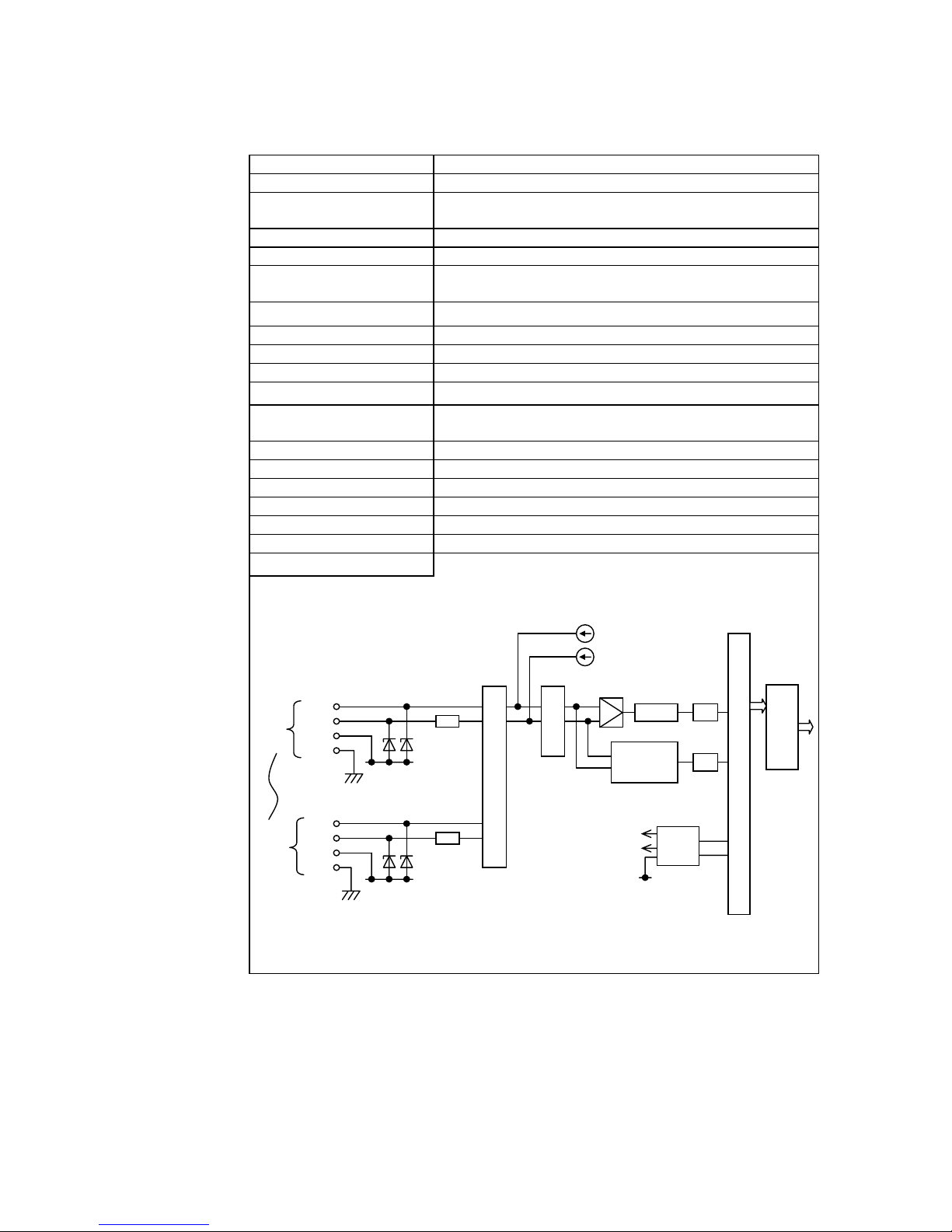
Type RT318
Category RTD ( Resistance Temperature Detector ) input
Resistance temperature
detectors
Measuring method Three-wire system
Load current 1 mA
Temperature measurement
range
Converted data 800 to 4000
Input channel 8 channels / module
Insulation Photo-coupler insulation (not isolated between the channels)
Conversion rate 400 ms / 8 channels
Resolution
Wire resistance correction
range
Overall accuracy ±
Tepaerature drift ±
Internal current consumption 5 Vdc, 600 mA or less
Insulation resistance
Withstand voltage 500 Vac, 1 minutes ( between internal and external circuits)
Weight 500 g
Internal circuit
1A
1B
CH1
1C
1G
8A
8B
8C
CH8
8G
Pt100
-50° to +270°C (-58° to +518°F)
12 bits / 0.025 % ( 0.1 °C / count )
Within 4Ω
0.3 % (at 25 °C)
100 ppm / °C
10 MΩ (500 Vdc)
Current source
1 mA
1 mA
Rref
AG
Input filter
Multiplexer
Rref
AG
AMP
ADC
Wire break
detection
+15V
-15V
DC/DC
0V
PC : Photo-coupler
PC
PC
5 Vdc
Buffer
memor
Internal circuit
1
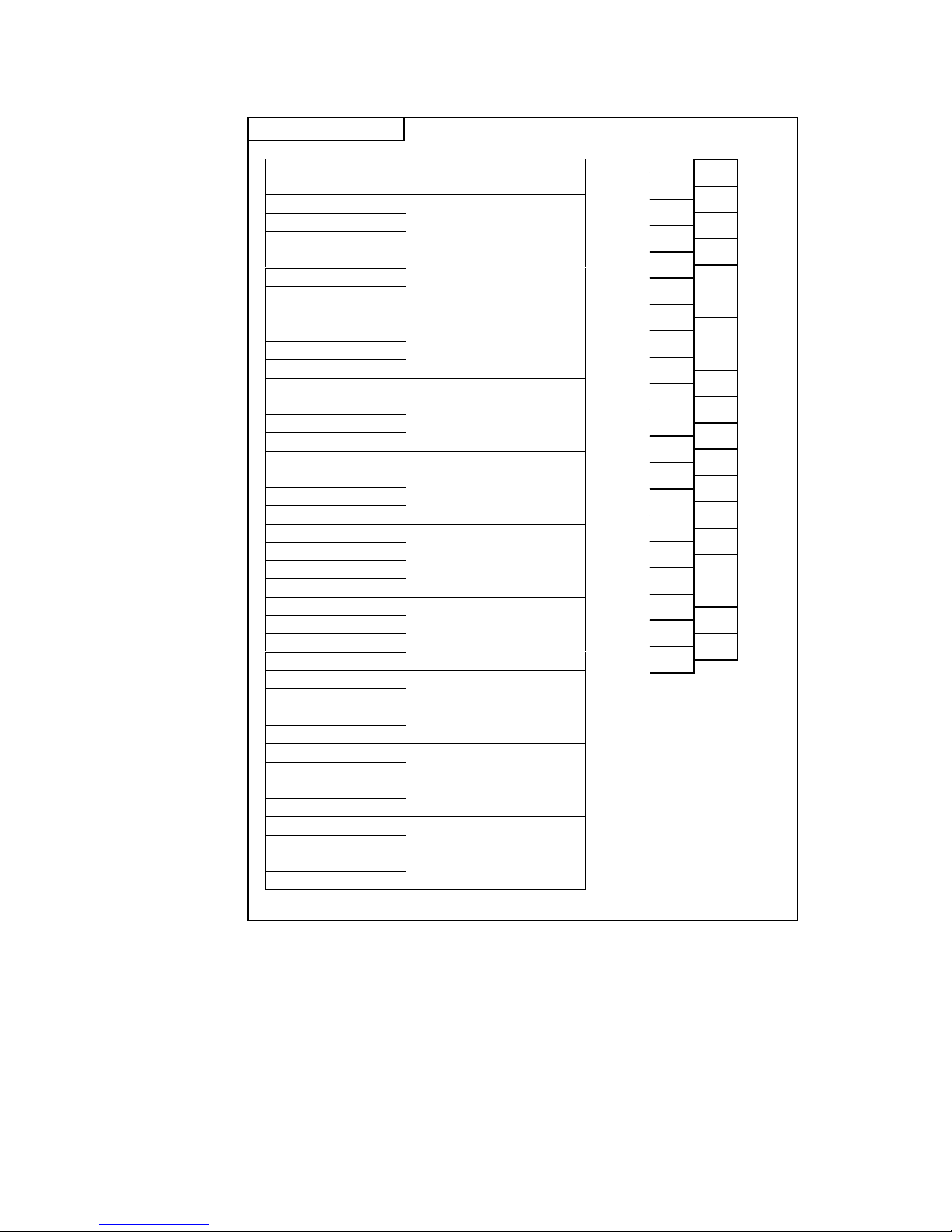
Terminal connections
Terminal
No.
1 (NC) No Connection
2 (NC) ( do not connect any wire )
3 (NC)
4 (NC)
5 (NC)
6 (NC)
7 1A
8 1B RTD input channel 1
9 1C
10 1G
11 2A
12 2B RTD input channel 2
13 2C
14 2G
15 3A
16 3B RTD input channel 3
17 3C
18 3G
19 4A
20 4B RTD input channel 4
21 4C
22 4G
23 5A
24 5B RTD input channel 5
25 5C
26 5G
27 6A
28 6B RTD input channel 6
29 6C
30 6G
31 7A
32 7B RTD input channel 7
33 7C
34 7G
35 8A
36 8B RTD input channel 8
37 8C
38 8G
Terminal
name
Function
N.C.
N.C.
N.C.
1B
1G
2B
2G
3B
3G
4B
4G
5B
5G
6B
6G
7B
7G
8B
8G
2
4
6
8
10
12
14
16
18
20
22
24
26
28
30
32
34
36
38
1
3
5
7
9
11
13
15
17
19
21
23
25
27
29
31
33
35
37
RT318
N.C.
N.C.
N.C.
1A
1C
2A
2C
3A
3C
4A
4C
5A
5C
6A
6C
7A
7C
8A
8C
2

RT318
(1) Status indicator LEDs (PWR/FLT/RUN)
1) PWR
PWR will be lit in normal state of analog power supply, and will not be lit in abnormal state.
2) FLT
FLT will be lit if an error has occurred in the module.
3) RUN
RUN will be lit in normal state of the module, and will not be lit in abnormal state.
Name Lit ● Not lit ○
PWR Normal state abnormal state
FLT Error occurred Normal state
RUN Normal state abnormal state
(1)
(2) Unused terminals
(3) RTD input terminals (1A/1B/1C/1G to 8A/8B/8C/8G)
These terminals will be connected with external RTD signals.
(2)
(3)
3

RT318
(
)
How to wire
Shielded twisted cable
Internal circuit side
RTD
(Pt100)
RTD : Resistance
Temperature Detector
n : Channel number
AG : Analog ground
FG : Frame ground
nA
nB
nC
nG
AG
FG
If measurement values are unstable due to noise influences, change the grounding for
the shield in the following order for stable measurement.
(1)
Shielded twisted cable
RTD
(Pt100)
Internal circuit side
nA
nB
nC
nG
AG
FG
(2)
RTD
Pt100
Shielded twisted cable
Internal circuit side
nA
nB
nC
nG
AG
FG
(3)
RTD
(Pt100)
Shielded twisted cable
Internal circuit side
nA
nB
nC
nG
FG
Supplementary
To minimize the influences of the wire resistance, be sure the wire
length to be same of each cable from the terminal nA , nB o r nC to
RTD.
4
 Loading...