

Page 1

FILE NO. 020-200523
DOCUMENT CREATED IN JAPAN, Sept., 2005
SERVICE MANUAL
Projection Television
56HM195
62HM195
72HM195
TOSHIBA CORPORATION 2005
Published in Japan Sep. 2005 (YC)
Page 2

TABLE OF CONTENTS
SAFETY INSTRUCTIONS .............................................................................................................................................. 3
SERVICE MODE ............................................................................................................................................................ 4
SETTING & ADJUSTING DATA ...................................................................................................................................... 9
LAMP UNIT REPLACEMENT ....................................................................................................................................... 10
LIGHT ENGINE REPLACEMANT.................................................................................................................................
PARTS REPLACEMENT IN LIGHT ENGINE...............................................................................................................
EXPLODED VIEW ........................................................................................................................................ ................ 17
MECHANICAL DISASSEMBLY .................................................................................................................................... 18
CHASSIS REPLACEMENT PARTS LIST ..................................................................................................................... 19
PC BOARDS TOP AND BOTTOM VIEW ..................................................................................................................... 29
TERMINAL VIEW OF TRANSISTORS ......................................................................................................................... 47
CIRCUIT BLOCK DIAGRAM ........................................................................................................................................ 52
APPENDIX:
CIRCUIT DIAGRAM
13
14
-
2
-
Page 3
SAFETY INSTRUCTIONS
SAFETY PRECAUTION
WARNING: Service should not be attempted by anyone unfamiliar with the necessary precautions on this receiver. The following
are the necessary precautions to be observed before servicing this chassis.
1. An isolation transformer should be connected in the power line between the receiver and the AC line before any service is
performed on the receiver.
2. When replacing a chassis in the cabinet, always be certain that all the prospective devices are put back in place, such as;
non-metallic control knobs, insulating covers, shields, isolation resistor-capacitor network etc.
PRODUCT SAFETY NOTICE
Many electrical and mechanical parts in this chassis have special safety-related characteristics. These characteristics are
often passed unnoticed by a visual inspection and the protection afforded by them cannot necessarily be obtained by using
replacement components rated for higher voltage, wattage, etc. Replacement parts which have these special safety characteristics are identified in this manual and its supplements; electrical components having such features are identified by the
international hazard symbols on the schematic diagram and the parts list.
Before replacing any of these components, read the parts list in this manual carefully. The use of substitute replacement
parts which do not have the same safety character istics as specified in the parts list may create shock, fire, or other hazards.
-
3
-
Page 4
SERVICE MODE
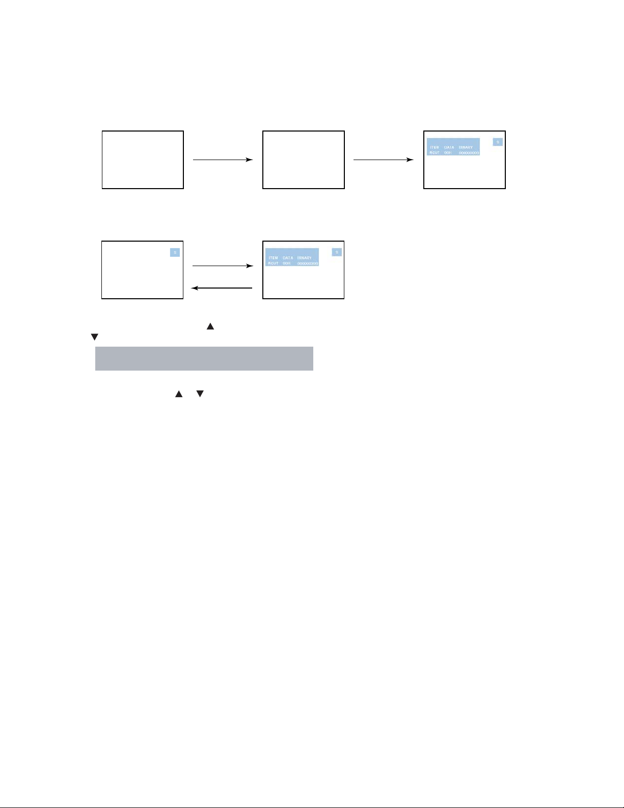
1. ENTERING SERVICE MODE
1) Press MUTE button twice
on Remote Control.
MUTE
2) Press MUTE button
again and keep pressing.
2. DISPLAYING THE ADJUSTMENT MENU
1) Press MENU button on Remote Control.
Service mode
Press
Press
Adjustment mode
3. SELECTING THE ADJUSTING ITEMS
1) Every pressing of CHANNEL button in the service mode changes the adjustment items in the order of table-2.
( button for reverse order)
Refer to table-1 for preset data of adjustment mode.
(See SETTING & ADJUSTING DATA on page 9)
3) While pressing the MUTE button,
press MENU button on TV set.
(Service mode display)
4. ADJUSTING THE DATA
1) Pressing of VOLUME or button will change the value of data in the range from 00H to FFH. The variable range
depends on the adjusting item.
5. EXIT FROM SERVICE MODE
1) Pressing POWER button to turn off the TV once.
-
4
-
Page 5
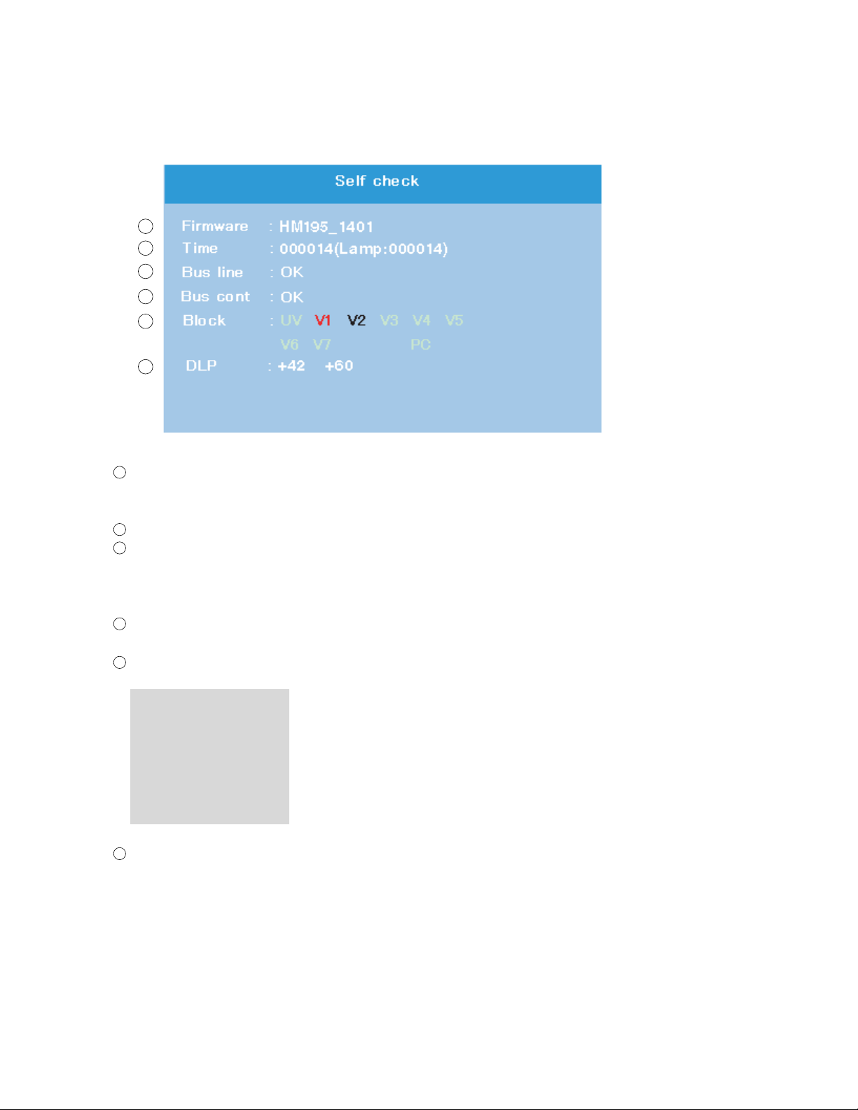
6. SELF DIAGNOSTIC FUNCTION
1) Press “9” button on Remote Control during display of adjustment menu in the service mode.
The diagnosis will begin to check if interface among IC’s is executed properly.
2) During diagnosis, the following displays are shown.
1
2
3
4
5
6
1
Firmware :
Version information of microprocessor
In case of file name : HM195 and Version : 1401 indicates[HM195_1401].
2
Time : Total brightness hour of the projection lamp. (Unit : H)
3
Bus line : --"OK" is normal
"SCL-GND"(Red indication) : SCL-GND short circuit
"SDA-GND"(Red indication) : SDA-GND short circuit
"SCL-SDA"(Red indication) : SCL-SDA short circuit
Bus cont : --- "OK" is normal.
4
NG is abnormal(Red indication), when type name of semiconductor indicates.
Block
5
UV : TV reception mode
V1 : VIDEO 1 input mode
V2 : VIDEO 2 input mode
V3 : VIDEO 3 input mode
V4 : ColorStream HD-1 IN
V5 : ColorStream HD-2 IN
V6 : HDMI IN 1
V7 : HDMI IN 2
6
DLP : Thermal sensor values information that indicates both of nearby the projection lamp and DMD
microprocessor into the unit.
-5-
Page 6
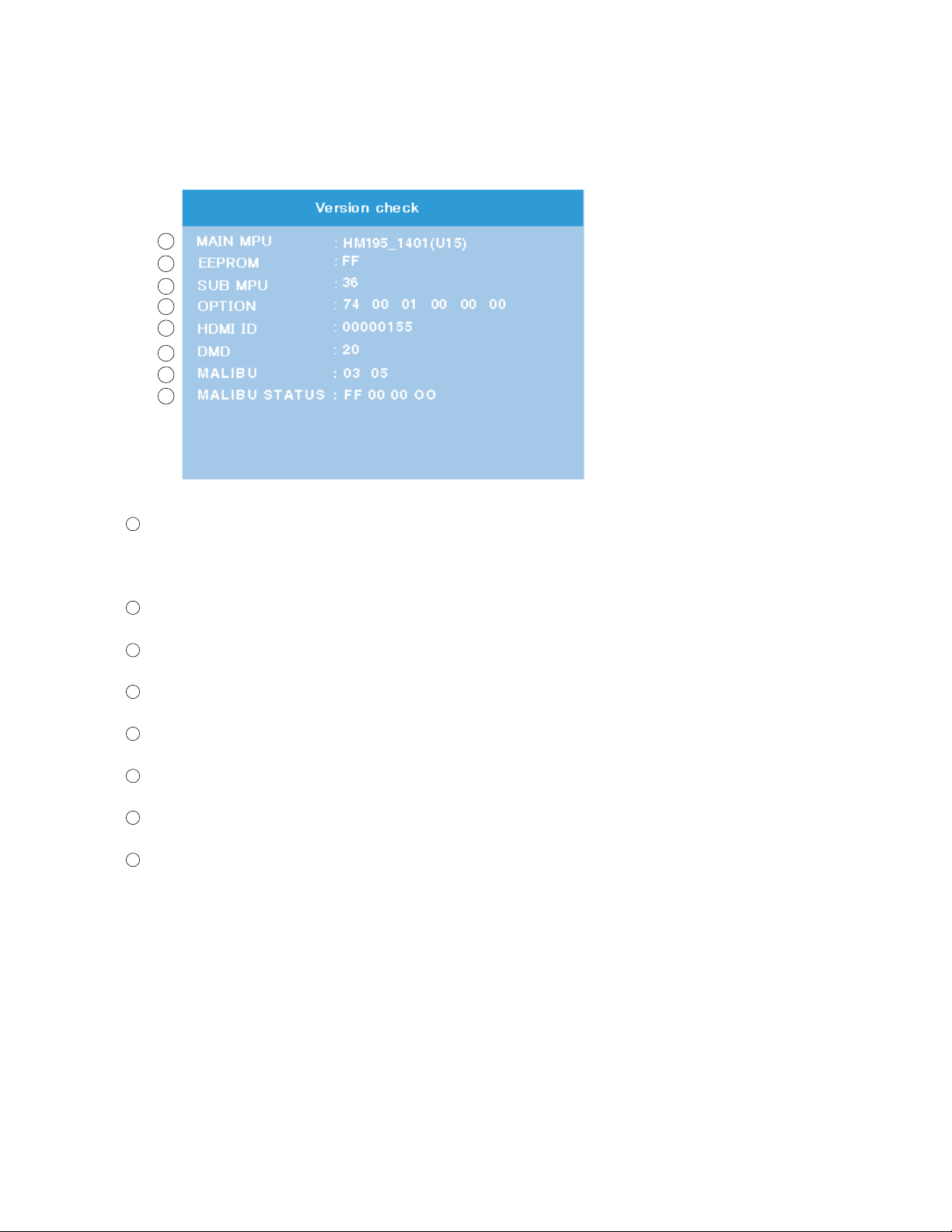
7. VERSION CHECK MODE
1) Press “9” button twice on Remote Control during display of adjustment menu in the service mode. The version of main
MPU will begin to check.
2) During Version Check, the following displays are shown.
1
2
3
4
5
6
7
8
1
MAIN MPU :
Version information of microprocessor
In case of file name : HM195, Version 1401 for Code Program Version
and (U15) for OSD Version indicates [HM195_1401(U15)]
2
EEPROM :
Version information of EEPROM : Display 1 byte data.
3
SUB MPU :
Version information of SUB MPU : Display 1 byte data.
4
OPTION :
Option information : Display six numbers of 1 byte data.
5
HDMI ID :
HDMI ID information : Display 4 byte data.
6
DMD :
Version information of DMD optical engine : Display 1 byte data.
7
MALIBU :
MALIBU information : Display two numbers of 1 byte data.
8
MALIBU STATUS :
MALIBU STATUS information : Display four numbers of 1 byte data.
-6-
Page 7
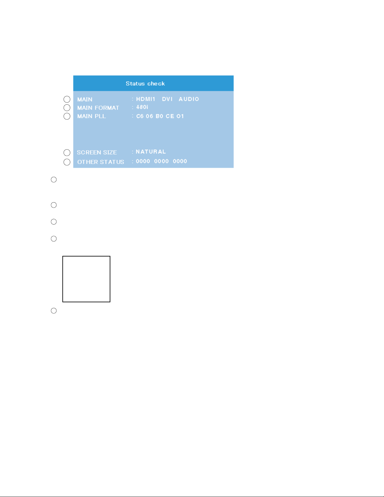
8. STATUS CHECK MODE
1) Press “9” button thrice on Remote Control during display of adjustment menu in the service mode. The status of this
model will begin to check.
2) During Status Check, the following displays are shown.
1
2
3
4
5
1
MAIN :
Main source information :
Display RF position number (1 - 135) on the main screen, or Input Source (HDMI1/2, DVI, AUDIO etc.)
2
MAIN FORMAT :
Display Video and PC format information
3
MAIN PLL :
Main PLL information : Display 1 byte data at five.
4
SCREEN SIZE :
Display the screen size as follows.
Theater Wide 1
Theater Wide 2
Theater Wide 3
FULL
NATURAL
5
OTHER STATUS :
Other status information : Display three numbers of 2 byte data.
-7-
Page 8
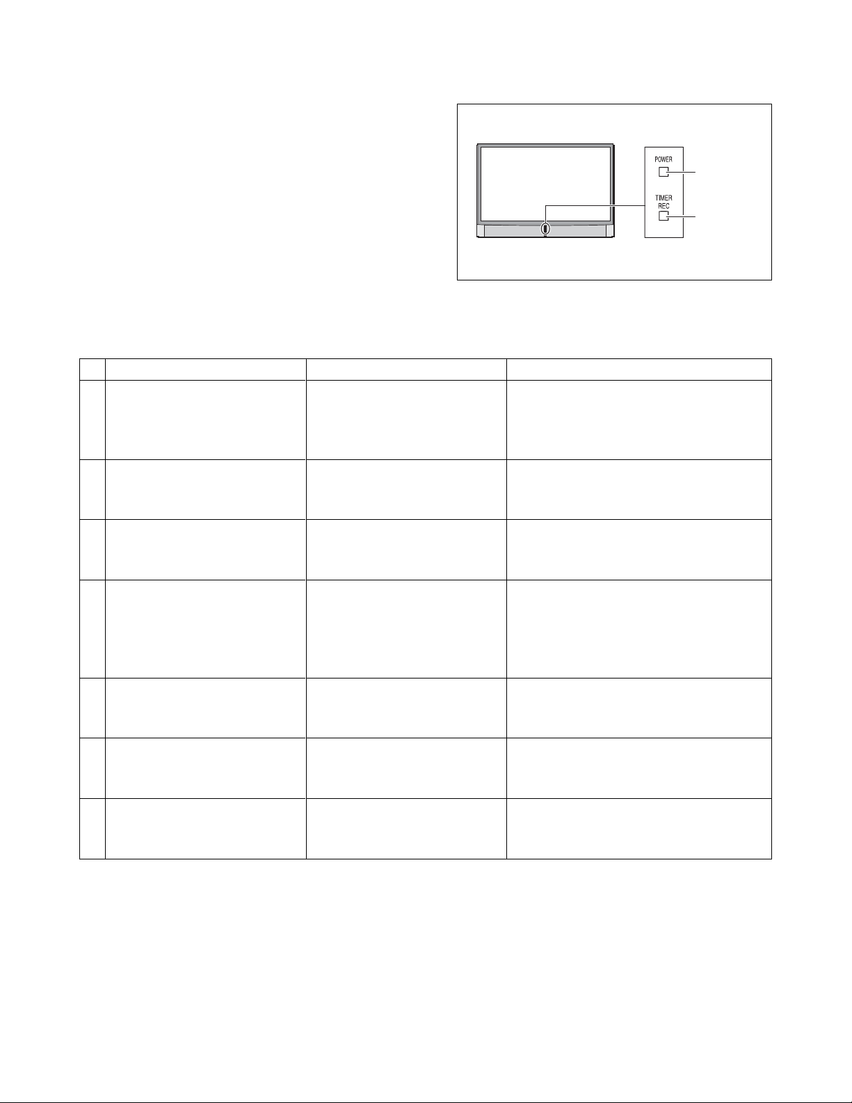
9. LED indications
The yellow and blue LED lights on the TV (at the bottom center of the TV) indicate the TV’s status, as described below:
´ Blue ON (solid) and Yellow OFF = The TV power cord is
plugged in.
´ Yellow ON (solid) and Blue OFF = A recording is in
progress while the TV is OFF.
´ Blue ON (solid) and Yellow ON (solid) = A recording is in
progress while the TV is ON.
Yellow and/or Blue blinking (see table below).
Note: If the TV loses A/C power (e.g., a power outage oc-
curs or the power cord is unplugged), when power is
restored, the yellow LED will blink while the TV is
booting until the remote control is usable. This is
normal and is not a sign of malfunction.
Blue LED
Yellow LED
TV front
LED
Yellow blinks continuously at 3-
1
second intervals.
Blue blinks continuously at 0.5-
second intervals.
Yellow blinks continuously at 0.5-
2
second intervals;
Blue is ON (solid).
Yellow and Blue blink continu-
3
ously at 1-second intervals.
Yellow is OFF;
4
Blue blinks at 0.2-second inter-
vals 4 times (repeat).
Yellow is OFF;
5
Blue blinks continuously at 0.5-
second intervals.
Yellow is OFF;
6
Blue blinks continuously at 1-
second intervals.
Yellow is OFF;
7
Blue blinks at 0.2-second inter-
vals 3 times (repeat).
Condition
The lamp unit door is not seated
properly.
The lamp is not working properly.
The lamp is not working properly
after the eighth automatic restart
(see item #2).
An abnormal temperature
increase has occurred.
Abnormal operation
(including cooling fan stop).
Abnormal operation of BUS line.
The color wheel has stopped.
Solution
Turn OFF the TV and unplug the power cord.
Review “How to replace the lamp unit” on
pages 10–12 to ensure that the lamp door is
installed securely.
The TV will automatically try to restart itself
eight times (see item #3).
Turn the TV OFF and then ON again. If the
problem persists, replace the lamp unit (see
pages 10–12).
Turn OFF the TV. Check to make sure all
slots and openings in the TV cabinet are not
covered, blocked, or dusty. Turn ON the TV
again. If the problem persists, contact a
Toshiba Authorized Service Center.
Turn OFF the TV and unplug the power cord.
Plug the power cord in again and turn ON
the TV.
Turn OFF the TV and unplug the power cord.
Plug the power cord in again and turn ON
the TV.
Turn OFF the TV and unplug the power cord.
Plug the power cord in again and turn ON
the TV.
– 8 –
Page 9
SETTING & ADJUSTING DATA
SERVICE MODE
ADJUSTING ITEMS AND DATA IN THE SERVICE MODE:
Item Name of adjustment
RCUT R CUT OFF
GCUT G CUTOFF
BCUT B CUT OFF
GDRV G DRIVE
BDRV B DRIVE
RDRV
BRTC
∗
COLC
∗
UVTT
∗
CNTX
∗
CNTCG G CONTRAST CENTER
CNTCR R CONTRAST CENTER
CNTCB B CONTRAST CENTER
HPOS H-POSITION 00H
Note:
The image system data of ∗mark items are different by each image format.
The RF-Signal value is indicated in the table.
Retention the HPOS and VPOS data to EEPROM of Malibu.
Retention the CWDH and CWDL data to EEPROM of DMD.
R DRIVE
BRIGHTNESS CENTER
COLOR CENTER
BASE BAND TINT
CONTRAST MAX
Preset Data
00H
00H
00H
80H
80H
80H
FDH
C8H
FEH
80H
64H
64H
64H
Table-1
Item Name of adjustment
VPOS V-POSITION
CWDH
CWDL
DMDB DMD BIAS
OPT1 TV SET OPTION 1
OPT2 TV SET OPTION 2
OPT3 TV SET OPTION 3
PLLW0 PLL WAIT TIME
PLLW1 PLL WAIT TIME
PLLW2 PLL WAIT TIME
PLLW3 PLL WAIT TIME
PLLW4 PLL WAIT TIME
PLLW5 PLL WAIT TIME
COLOR WHEEL DELAY (HIGH)
COLOR WHEEL DELAY (LOW)
Preset Data
00H
00H
74H
03H
74H
00H
01H
14H
03H
0FH
05H
14H
04H
-9 -
Page 10

LAMP UNIT REPLACEMENT
Cautions when replacing LAMP UNIT (E998Z; PJ-D95-LMP)
The light source for this TV is a mercury lamp with internal atmospheric
pressure that increases during use. The lamp has a limited service life
that varies depending on user settings. If you use the lamp beyond its
service life:
you may notice a reduction in the colors and/or brightness of the picture; and
the strength of the quartz glass in the lamp will be reduced and the
lamp may rupture (often making a loud noise when this happens). If
the lamp reputres, the TV will not operate until the lamp unit is replaced.
Note: The lamp unit is designed so broken lamp glass remains se-
Note: The lamp unit is designed so broken lamp glass remains se-
curely inside the lamp unit.
curely inside the lamp unit.
CAUTION: Always handle the lamp unit with care.
The lamp unit in this TV was designed for safe replacement by consumers; however, if the lamp unit is subjected to intentional abuse (such as excessive mechanical abuse or handling by
children or pets), the unit may break, exposing edges or pinch points.
When to replace the lamp unit
You should replace the lamp unit:
if the picture darkens and/or colors fade;
if the lamp does not light; or
If you hear a loud noise and the picture goes black, which may indicate a lamp rupture (LED indication #8). See LED indications on
page 6.
Note: Be sure wear the gloves before replacing the lamp unit.
-
10
-
Page 11
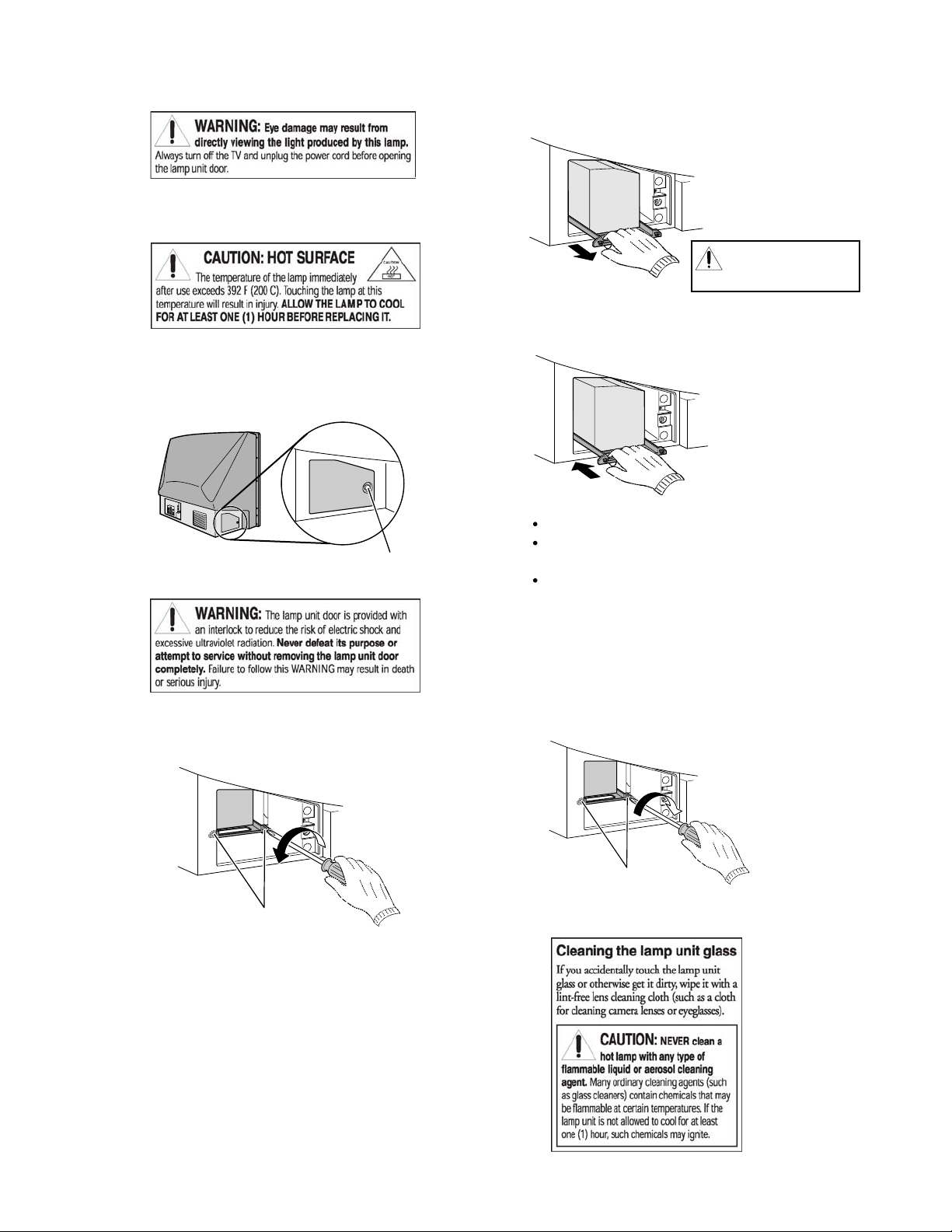
1. Turn off the TV and unplug the power cord.
2. STOP! Allow the lamp to cool for at least one (1) hour
before replacing it.
3. On the lamp unit door on the side of the TV, loosen the
screw using a manual screw driver, and then remove
the lamp unit door.
TV back
Lamp unit door detail
loosen screw using
manual screwdriver
5. Grasp the lamp unit handle and gently pull the lamp unit
straight out of the TV. Set the old lamp unit aside.
Note: Wear soft, lint-free
gloves
when replacing
the lamp unit.
6. Carefully insert the new lamp unit straight into the TV
until it is fully seated.
Note :
Never subject the lamp unit to excessive shock.
Never touch the lamp unit glass or otherwise get it
dirty.
Doing so may affect the image quality and reduce
the service life of the lamp. See “Cleaning the lamp
unit glass” below.
4. Using a manual screwdriver, loosen the two screws on
the lamp unit.
Lamp unit screws
7. Using a manual screwdriver, tighten two lamp unit
screws.
Note:Hand-tighten only. Do not use an electric screwdriver.
Lamp unit screws
(use manual screwdriver only)
-
11
-
Page 12
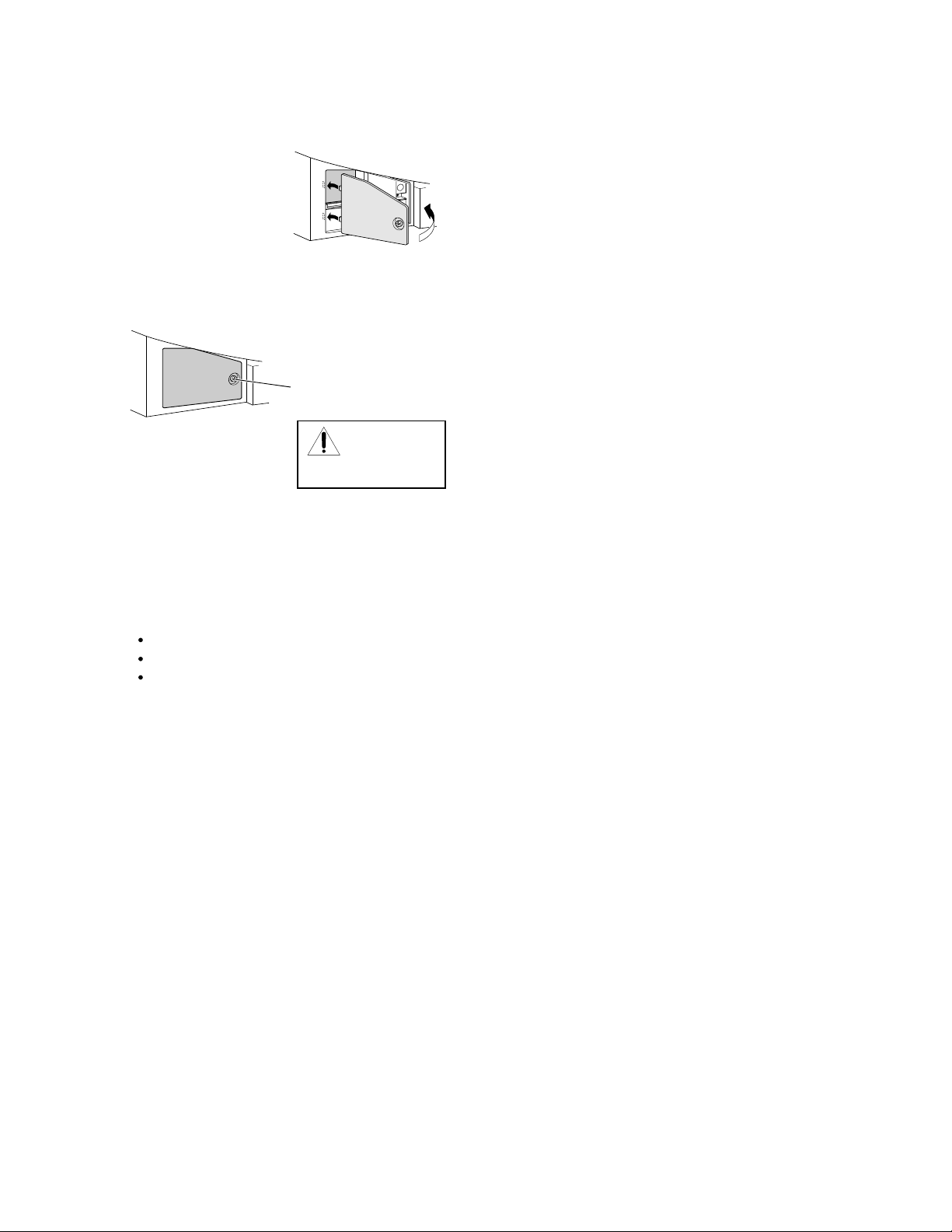
8. Reattach the lamp unit door, making sure to insert the
hooks on the left side of the lamp unit door inside the
opening in the TV cabinet.
Insert the hooks inside
the TV cabinet opening.
Lamp unit door
9. Replace the screw and hand-tighten using a manual
screwdriver.
Hand tighten using
manual screwdriver
Lamp unit door
NOTE :
Make sure
the lamp unit door is
installed securely; otherwise,
the TV may not turn on.
10. Plug in the power cord and turn on the TV. After the
initial warmup period (which may take several seconds
for full picture brightness), the TV should operate normally. If any of the following conditions exist, turn off the
TV, unplug the power cord, and repeat steps 1-9 to ensure that the lamp unit and lamp unit door are installed
correctly:
No picture
Dark picture
TV will not turn on
-12-
Page 13

LIGHT ENGINE REPLACEMENT
Cautions when replacing LIGHT ENGINE
LIGHT ENGINE UNIT:
A271 : LV-682 TB
(Including with E998Z, SK01 to SK04, SK06,SK08 and SK09.)
LIGHT ENGINE is a heart of the TV and emits high heat.
Make sure to replace it after turning off the TV and wait
for sufficient cool down. (More than one hour is recommended.)
Do not impact during replacement; otherwise, some
parts may be damaged.
Do not touch optical lens. Adhesion of dirt may deteriorate its performance.
Do not loosen any screw other than those to be removed
for adjustment or replacement.
LIGHT ENGINE emits ultraviolet rays when the TV is
ON. Make sure to be careful.
-
13
-
Page 14
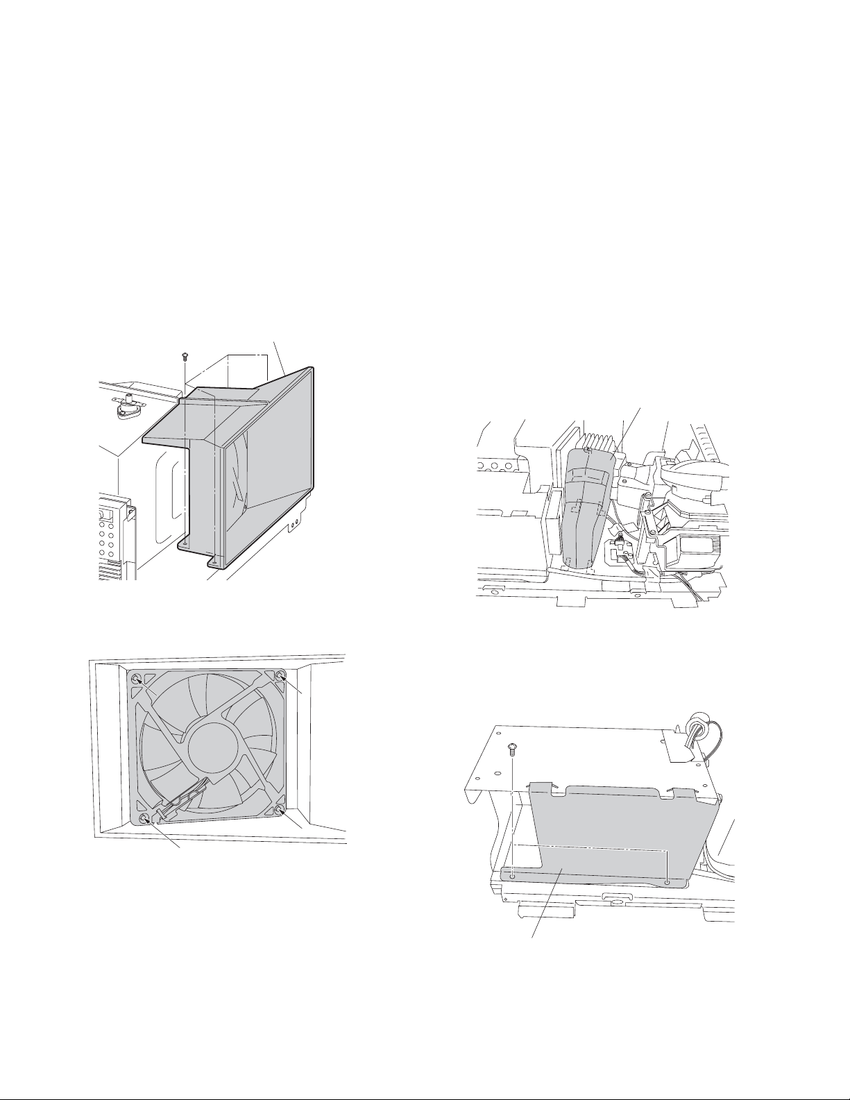
PARTS REPLACEMENT IN LIGHT ENGINE
1. Replacement of Lamp FAN (SK01)
1-1. Replace the FAN for cooling Lamp (SK01), remove the
4 screws on the FAN Hood, and remove the 4 pins by
pressing toward allows using a screwdriver, and the
remove the FAN for cooling Lamp.
NOTE:
Reinstalling the FAN for cooling Lamp, attach the 4 pins
by using removed them after replace the FAN.
4 screws
FAN Hood
2. Replacement of Ballast FAN (SK03)
2-1. Replace the FAN for cooling Ballast Power Unit (SK03),
remove the Ballast Hood, and remove the 2 screws on the
Ballast Case Cover.
2-2. Remove the 4 pins by pressing toward inside of the FAN
using a screwdriver, and then remove the 4 pins toward
allows as figure.
Remove the FAN for cooling Ballast Power Unit.
NOTE:
Reinstalling the FAN for cooling Ballast Power Unit,
attach the 4 pins by using removed them after replacing
the FAN.
Ballast Hood
4 pins
2 screws
Ballast Case Cover
– 14 –
Page 15

Ballast FAN (SK03)
4 pins
3. Replacement of DMD FAN (SK02) and FAN
Transfer Cable (SK09)
3-1. Replace the FAN for cooling Formatter Board, detach
the Fan Bracket with DMD FAN by removing the 4
screws on the bracket.
3-2. Remove the 2 screws from the bracket, and then
remove the FAN for cooling Formatter Board (SK02).
3-3. Disconnect and replace the FAN transfer cable between
Ballast and Formatter Boards (SK09).
DMD FAN (SK02)
2 screws
SK09
Formatter Board
Fan Bracket
2 screws
2 screws
4. Replacement of Thermostat (Lamp Sensor)
(SK04)
4-1. Replace the Thermostat (Lamp Sensor) (SK04),
remove 2 screws on the Thermostat.
2 screws
Thermostat (SK04)
– 15 –
Page 16

5. Replacement of Ballast to Formatter Board
Cables (SK06 and SK08)
5-1. Disconnect and replace the cable between Ballast and
Formatter Boards (SK06).
5-2. Disconnect and replace the cable between Smooth
Picture and Formatter Boards (SK08).
Formatter Board
SK06
6. LIGHT ENGINE UNIT
Location Parts No. Description
No.
SK08
A271 23405480 OPTICAL ENGINE LV-682 TB 0C 56HM195
(Incl. E998Z, SK01-SK04, SK06,SK08,SK09)
23405481 OPTICAL ENGINE LV-682 TB 0D 62HM195
(Incl. E998Z, SK01-SK04, SK06,SK08,SK09)
23405482 OPTICAL ENGINE LV-682 TB 0E 72HM195
(Incl. E998Z, SK01-SK04, SK06,SK08,SK09)
E998Z 23311153 EXCHANGE LAMP, PJ-D95-LMP
SK01 23587525 SERVICE KIT, LAMP FAN
SK02 23587526 SERVICE KIT, DMD FAN
SK03 23587527 SERVICE KIT, BALLAST FAN
SK04 23587528 SERVICE KIT, THERMOSTAT
SK06 23587536 SERVICE KIT, B TO F CABLE
SK08 23587538 SERVICE KIT, S TO F CABLE
SK09 23587539 SERVICE KIT, FAN TRANSFER CABLE
– 16 –
Page 17

EXPLODED VIEW
6 screws
15 screws
A421
(Incl. A411)
K601
A225
A102
W661A
W661B
3 screws
9 screws
A103
A201
A202
4 screws
UA06
UA07
3 screws
K501
K502
2 screws
A226
4 screws
W662A
W662B
A333
4 screws
UC01
A220
UV04
2 screws
6 screws
UA03
2 screws
1 screw
1 screw
A026
A184
4 screws
A100
A025
A271
UD01
SIGNAL UNIT BOARD
U105
IR BLASTER BOARD
U801
MAIN POWER BOARD
U104
BACK AV BOARD
U102
MOTHER BOARD
U107
U802
SUB POWER BOARD
TUNER RF BOARD
A100
UD02
SEINE DIGITAL BOARD
UD02
DIGITAL TUNER BOARD
– 17 –
1 screw
U105
1 screw
2 screws
UT
O
UF02
4 screws
2 screws
14 screws
2 screws
A422
A402
Page 18

MECHANICAL DISASSEMBLY
s
s
1. Rear Cover Removal
3. Mirror Removal
14 screws
A402
2. Touchpad & Bezel Ass'y Removal
15 screws
A102
A103
9 screws
4. Speaker Removal
4 screws
K601
6 screws
5. Bracket Removal
1 screw
W661B
W661A
3 screws
8 screws
W662B
8 screws
6. Optical Engine Removal
2 screws
3 screws
T
U
O
W662B
1 screw
1 screw
A271
2 screw
4 screws
2 screw
UF02
– 19 –
Page 19

CHASSIS AND CABINET REPLACEMENT PARTS LIST
WARNING: BEFORE SERVICING THIS CHASSIS, READ THE "SAFETY PRECAUTION" AND "PRODUCT SAFETY
NOTICE" ON PAGE 3 OF THIS MANUAL.
CAUTION: The international hazard symbols " " in the schematic diagram and the parts list designate components
which have special characteristics important for safety and should be replaced only with types identical to those in the
original circuit or specified in the parts list. The mounting position of replacements is to be identical with originals.
Before replacing any of these components, read carefully the PRODUCT SAFETY NOTICE. Do not degrade the safety
of the receiver through improper servicing.
NOTICE:
The part number must be used when ordering parts, in order to assist in processing, be sure to include the
Model number and Description.
The PC board assembly with
Capacitors ............. CD : Ceramic Disk PF : Plastic Film EL : Electrolytic
Resistors ............... CF : Carbon Film CC : Carbon Composition MF : Metal Film
OMF : Oxide Metal Film VR : Variable Resistor FR : Fusible Resistor
(All CD and PF capacitors are
mark is no longer available after the end of the production.
*
Model : 56/62/72HM195
±5%, 50V and all resistors, ±5%, 1/6W unless otherwise noted.)
Location Parts No. Description
No.
#1 : [56HM195]
#2 : [62HM195]
#3 : [72HM195]
CAPACITORS
C001 76100104 CERAMIC CHIP, 25V F 0.1UF Z
C002 76100104 CERAMIC CHIP, 25V F 0.1UF Z
C003 76100104 CERAMIC CHIP, 25V F 0.1UF Z
C004 76100104 CERAMIC CHIP, 25V F 0.1UF Z
C005 76100104 CERAMIC CHIP, 25V F 0.1UF Z
C006 76100104 CERAMIC CHIP, 25V F 0.1UF Z
C007 76100104 CERAMIC CHIP, 25V F 0.1UF Z
C008 76100104 CERAMIC CHIP, 25V F 0.1UF Z
C009 76100104 CERAMIC CHIP, 25V F 0.1UF Z
C010 76100104 CERAMIC CHIP, 25V F 0.1UF Z
C011 76100104 CERAMIC CHIP, 25V F 0.1UF Z
C012 76100104 CERAMIC CHIP, 25V F 0.1UF Z
C013 76100104 CERAMIC CHIP, 25V F 0.1UF Z
C014 76100104 CERAMIC CHIP, 25V F 0.1UF Z
C015 76100104 CERAMIC CHIP, 25V F 0.1UF Z
C016 76100104 CERAMIC CHIP, 25V F 0.1UF Z
C017 76100104 CERAMIC CHIP, 25V F 0.1UF Z
C018 76100104 CERAMIC CHIP, 25V F 0.1UF Z
C019 76100104 CERAMIC CHIP, 25V F 0.1UF Z
C020 76100104 CERAMIC CHIP, 25V F 0.1UF Z
C021 76100104 CERAMIC CHIP, 25V F 0.1UF Z
C022 76100104 CERAMIC CHIP, 25V F 0.1UF Z
C023 76100104 CERAMIC CHIP, 25V F 0.1UF Z
C024 76100104 CERAMIC CHIP, 25V F 0.1UF Z
C025 76100104 CERAMIC CHIP, 25V F 0.1UF Z
C026 76100104 CERAMIC CHIP, 25V F 0.1UF Z
C027 76100104 CERAMIC CHIP, 25V F 0.1UF Z
C028 76100104 CERAMIC CHIP, 25V F 0.1UF Z
C029 76100104 CERAMIC CHIP, 25V F 0.1UF Z
C030 76100104 CERAMIC CHIP, 25V F 0.1UF Z
C031 76100104 CERAMIC CHIP, 25V F 0.1UF Z
C032 76100104 CERAMIC CHIP, 25V F 0.1UF Z
C033 76100104 CERAMIC CHIP, 25V F 0.1UF Z
C034 76100104 CERAMIC CHIP, 25V F 0.1UF Z
C035 76100104 CERAMIC CHIP, 25V F 0.1UF Z
C036 76100104 CERAMIC CHIP, 25V F 0.1UF Z
C037 76100104 CERAMIC CHIP, 25V F 0.1UF Z
C038 76100104 CERAMIC CHIP, 25V F 0.1UF Z
C039 76100104 CERAMIC CHIP, 25V F 0.1UF Z
C040 76100104 CERAMIC CHIP, 25V F 0.1UF Z
C041 76100104 CERAMIC CHIP, 25V F 0.1UF Z
Location Parts No. Description
No.
C042 76100104 CERAMIC CHIP, 25V F 0.1UF Z
C043 76100104 CERAMIC CHIP, 25V F 0.1UF Z
C044 76100104 CERAMIC CHIP, 25V F 0.1UF Z
C045 76100104 CERAMIC CHIP, 25V F 0.1UF Z
C046 76100104 CERAMIC CHIP, 25V F 0.1UF Z
C047 76100104 CERAMIC CHIP, 25V F 0.1UF Z
C048 76100104 CERAMIC CHIP, 25V F 0.1UF Z
C049 76100104 CERAMIC CHIP, 25V F 0.1UF Z
C050 76100104 CERAMIC CHIP, 25V F 0.1UF Z
C051 76100104 CERAMIC CHIP, 25V F 0.1UF Z
C102 76665221 ELECTROLYTIC, 10V 220UF M 3A
C103 76109102 CERAMIC CHIP, 50V B 1000PF K
C104 76073084 ELECTROLYTIC, 50V 4.7UF M 3A
C120 76092730 CERAMIC CHIP, 16V B 0.1UF K
C151 76109102 CERAMIC CHIP, 50V B 1000PF K
C152 76109102 CERAMIC CHIP, 50V B 1000PF K
C161 76109102 CERAMIC CHIP, 50V B 1000PF K
C162 76105101 CERAMIC CHIP, 50V CH 100PF J
C164 76092730 CERAMIC CHIP, 16V B 0.1UF K
C601 76109391 CERAMIC CHIP, 50V B 390PF K
C602 76109391 CERAMIC CHIP, 50V B 390PF K
C603 76797100 ELECTROLYTIC, 50V 10UF M
C604 76797100 ELECTROLYTIC, 50V 10UF M
C605 76073084 ELECTROLYTIC, 50V 4.7UF M 3A
C606 76073084 ELECTROLYTIC, 50V 4.7UF M 3A
C607 76073052 ELECTROLYTIC, 25V 47UF M 3A
C608 76073052 ELECTROLYTIC, 25V 47UF M 3A
C609 76073068 ELECTROLYTIC, 35V 100UF M 3A
C610 76073086 ELECTROLYTIC, 50V 10UF M 3A
C612 76073039 ELECTROLYTIC, 16V 220UF M 3A
C613 76503042 PLASTIC FILM, 63V 0.12UF J
C614 76503042 PLASTIC FILM, 63V 0.12UF J
C615 76073095 ELECTROLYTIC, 50V 2200UF M 3A
C616 76073095 ELECTROLYTIC, 50V 2200UF M 3A
C661 76766479 ELECTROLYTIC, 50V 4.7UF M
C662 76797100 ELECTROLYTIC, 50V 10UF M
C663 76797100 ELECTROLYTIC, 50V 10UF M
C664 76108560 CERAMIC CHIP, 50V SL 56PF J
C665 76567103 PLASTIC FILM, 50V 0.01UF J
C666 76766479 ELECTROLYTIC, 50V 4.7UF M
C667 76794100 ELECTROLYTIC, 16V 10UF M
C668 76108560 CERAMIC CHIP, 50V SL 56PF J
C680 76073094 ELECTROLYTIC, 50V 1000UF M 3A
C681 76109103 CERAMIC CHIP, 50V B 0.01UF K
C687 76796101 ELECTROLYTIC, 35V 100UF M
C688 76795470 ELECTROLYTIC, 25V 47UF M
– 19 –
Page 20

Location Parts No. Description
No.
C801 76503004 PLASTIC FILM, AC275V 0.47UF M
C803 76503002 PLASTIC FILM, AC275V 0.22UF M
C805 76092281 CERAMIC DISC, AC250V E 4700PF
C808 76095634 PLASTIC FILM, 630V 0.01UF H
C809 76086067 CHEMICON 200V 102M LGQ2D102MESHTL
C810 76086067 CHEMICON 200V 102M LGQ2D102MESHTL
C811 76092567 CERAMIC DISC, AC250V E 1000PF M
C812 76092567 CERAMIC DISC, AC250V E 1000PF M
C815 76285104 CERAMIC CHIP, 50V B 0.1UF K
C816 76669470 ELECTROLYTIC, 50V 47UF M
C817 76092179 CERAMIC CHIP, 25V B 0.22UF K
C818 76285104 CERAMIC CHIP, 50V B 0.1UF K
C819 76214102 CERAMIC DISC, 500V B 1000PF K
C820 76092463 CERAMIC CHIP, 16V B 0.22UF K
C821 76092343 CERAMIC DISC, 2KV 680PF K
C822 76092344 CERAMIC DISC, 2KV 820PF K
C823 76092337 CERAMIC DISC, 2KV 220PF K
C824 76109472 CERAMIC CHIP, 50V B 4700PF K
C825 76503117 PLASTIC FILM CQ92 T 800V 33000PF J
C826 76092338 CERAMIC DISC, 2KV R 270PF K
C827 76503053 PLASTIC FILM, 63V 1UF J
C828 76214103 CERAMIC DISC, 500V B 0.01UF K
C829 76678229 ELECTROLYTIC, 200V 2.2UF M
C840 76092730 CERAMIC CHIP, 16V B 0.1UF K
C855 76073157 ELECTROLYTIC, 16V 1500UF M 3A
C856 76073157 ELECTROLYTIC, 16V 1500UF M 3A
C857 76073172 ELECTROLYTIC, 25V 1000UF M 3A
C860 76073205 ELECTROLYTIC CE04P 50V 470UF M 3A
C870 76092178 CERAMIC CHIP, 25V B 0.1UF K
C898 76092178 CERAMIC CHIP, 25V B 0.1UF K
C899 76092567 CERAMIC DISC, AC250V E 1000PF M
C8905 76666221 ELECTROLYTIC, 16V 220UF M
C8910 76092738 CERAMIC CHIP, 25V B 0.47UF K
C8911 76073151 ELECTROLYTIC, 16V 120UF M 3A
C8920 76073053 ELECTROLYTIC, 25V 100UF M 3A
C8921 76092738 CERAMIC CHIP, 25V B 0.47UF K
C8922 76667470 ELECTROLYTIC, 25V 47UF M 3A
C8923 76666331 ELECTROLYTIC, 16V 330UF M
C8924 76092730 CERAMIC CHIP, 16V B 0.1UF K
C8931 76092738 CERAMIC CHIP, 25V B 0.47UF K
C8932 76667470 ELECTROLYTIC, 25V 47UF M 3A
C8933 76666331 ELECTROLYTIC, 16V 330UF M
C8934 76092730 CERAMIC CHIP, 16V B 0.1UF K
C8960 76092616 CERAMIC CHIP, 16V B 0.33UF K
C8961 76092730 CERAMIC CHIP, 16V B 0.1UF K
CB01 76794470 ELECTROLYTIC, 16V 47UF M
CB51 76590103 PLASTIC FILM, 50V 0.01UF J
CB52 76794470 ELECTROLYTIC, 16V 47UF M
CB53 76503041 PLASTIC FILM , 63V 0.1UF J
CB54 76436221 CERAMIC DISC, 50V SL 220PF J
CB55 76797010 ELECTROLYTIC, 50V 1UF M
CB56 76794470 ELECTROLYTIC, 16V 47UF M
CB58 76794470 ELECTROLYTIC, 16V 47UF M
CB59 76590103 PLASTIC FILM, 50V 0.01UF J
CB60 76794100 ELECTROLYTIC, 16V 10UF M
CB61 76503041 PLASTIC FILM , 63V 0.1UF J
CB82 76567474 PLASTIC FILM, 50V 0.47UF J
CB503 76092730 CERAMIC CHIP, 16V B 0.1UF K
CB504 76794100 ELECTROLYTIC, 16V 10UF M
CB505 76092730 CERAMIC CHIP, 16V B 0.1UF K
CB506 76092795 CERAMIC CHIP, 6.3V B 2.2UF K
CB507 76092730 CERAMIC CHIP, 16V B 0.1UF K
CB508 76092795 CERAMIC CHIP, 6.3V B 2.2UF K
CB509 76794101 ELECTROLYTIC, 16V 100UF M
CB510 76092795 CERAMIC CHIP, 6.3V B 2.2UF K
CC01 76109102 CERAMIC CHIP, 50V B 1000PF K @U104
76092730 CERAMIC CHIP, 16V B 0.1UF K @UC01
CC02 76109102 CERAMIC CHIP, 50V B 1000PF K @U104
76092730 CERAMIC CHIP, 16V B 0.1UF K @UC01
CC03 76109102 CERAMIC CHIP, 50V B 1000PF K @U104
76092730 CERAMIC CHIP, 16V B 0.1UF K @UC01
CC04 76109102 CERAMIC CHIP, 50V B 1000PF K @U104
76619100 ELECTROLYTIC CHIP, 16V 10UF M @UC01
CC05 76109102 CERAMIC CHIP, 50V B 1000PF K @U104
76092730 CERAMIC CHIP, 16V B 0.1UF K @UC01
CC06 76109102 CERAMIC CHIP, 50V B 1000PF K @U104
Location Parts No. Description
No.
76092730 CERAMIC CHIP, 16V B 0.1UF K @UC01
CC07 76109102 CERAMIC CHIP, 50V B 1000PF K @U104
76619100 ELECTROLYTIC CHIP, 16V 10UF M @UC01
CC08 76109102 CERAMIC CHIP, 50V B 1000PF K @U104
76092730 CERAMIC CHIP, 16V B 0.1UF K @UC01
CC09 76109102 CERAMIC CHIP, 50V B 1000PF K @U104
76092730 CERAMIC CHIP, 16V B 0.1UF K @UC01
CC10 76109102 CERAMIC CHIP, 50V B 1000PF K @U104
76092730 CERAMIC CHIP, 16V B 0.1UF K @UC01
CC11 76109102 CERAMIC CHIP, 50V B 1000PF K @U104
76619100 ELECTROLYTIC CHIP, 16V 10UF M @UC01
CC12 76109102 CERAMIC CHIP, 50V B 1000PF K @U104
76092538 CERAMIC CHIP, 10V F 1UF Z @UC01
CC13 76109102 CERAMIC CHIP, 50V B 1000PF K @U104
76092730 CERAMIC CHIP, 16V B 0.1UF K @UC01
CC14 76109102 CERAMIC CHIP, 50V B 1000PF K @U104
76092730 CERAMIC CHIP, 16V B 0.1UF K @UC01
CC15 76109102 CERAMIC CHIP, 50V B 1000PF K @U104
76619100 ELECTROLYTIC CHIP, 16V 10UF M @UC01
CC16 76109102 CERAMIC CHIP, 50V B 1000PF K @U104
76092730 CERAMIC CHIP, 16V B 0.1UF K @UC01
CC17 76619100 ELECTROLYTIC CHIP, 16V 10UF M
CC18 76092730 CERAMIC CHIP, 16V B 0.1UF K
CC19 76092730 CERAMIC CHIP, 16V B 0.1UF K
CC20 76619100 ELECTROLYTIC CHIP, 16V 10UF M
CC21 76092730 CERAMIC CHIP, 16V B 0.1UF K
CC22 76092538 CERAMIC CHIP, 10V F 1UF Z
CC24 76092538 CERAMIC CHIP, 10V F 1UF Z
CC25 76092538 CERAMIC CHIP, 10V F 1UF Z
CC26 76092730 CERAMIC CHIP, 16V B 0.1UF K
CC27 76092730 CERAMIC CHIP, 16V B 0.1UF K
CC28 76619102 ELECTROLYTIC CHIP, 16V 47UF M
CC30 76619100 ELECTROLYTIC CHIP, 16V 10UF M
CC31 76092730 CERAMIC CHIP, 16V B 0.1UF K
CC33 76092730 CERAMIC CHIP, 16V B 0.1UF K
CC34 76092730 CERAMIC CHIP, 16V B 0.1UF K
CC36 76619100 ELECTROLYTIC CHIP, 16V 10UF M
CC40 76092538 CERAMIC CHIP, 10V F 1UF Z
CC41 76092730 CERAMIC CHIP, 16V B 0.1UF K
CC42 76109103 CERAMIC CHIP, 50V B 0.01UF K
CE01 76503002 PLASTIC FILM, AC275V 0.22UF M
CE04 76092281 CERAMIC DISC, AC250V E 4700PF
CE05 76092281 CERAMIC DISC, AC250V E 4700PF
CE08 76503253 PLASTIC FILM, 1250VH 0.01UF H
CE09 76092337 CERAMIC DISC, 2KV 220PF K
CE10 76073217 ELECTROLYTIC, 200V 560UF M
CE11 76092565 CERAMIC DISC, AC250V B 470PF K
CE12 76092565 CERAMIC DISC, AC250V B 470PF K
CE13 76092565 CERAMIC DISC, AC250V B 470PF K
CE19 76073019 ELECTROLYTIC, 10V 470UF M 3A
CE30 76073183 ELECTROLYTIC, 35V 220UF M
CE31 76092730 CERAMIC CHIP, 16V B 0.1UF K
CE32 76073153 ELECTROLYTIC, 16V 470UF M 3A
CE33 76092730 CERAMIC CHIP, 16V B 0.1UF K
CE34 76109103 CERAMIC CHIP, 50V B 0.01UF K
CE35 76073168 ELECTROLYTIC CE04P 25V 330UF M 3A
CE36 76092730 CERAMIC CHIP, 16V B 0.1UF K
CE37 76073153 ELECTROLYTIC, 16V 470UF M 3A
CE38 76092730 CERAMIC CHIP, 16V B 0.1UF K
CE39 76109103 CERAMIC CHIP, 50V B 0.01UF K
CE40 76666470 ELECTORLYTIC, 16V 47UF M 3A
CE41 76092616 CERAMIC CHIP, 16V B 0.33UF K
CE42 76073137 ELECTROLYTIC CE04P 10V 100UF M 3A
CE48 76073168 ELECTROLYTIC CE04P 25V 330UF M 3A
CE49 76073183 ELECTROLYTIC, 35V 220UF M
CE50 76667470 ELECTROLYTIC, 25V 47UF M 3A
CE51 76092738 CERAMIC CHIP, 25V B 0.47UF K
CE52 76073151 ELECTROLYTIC, 16V 120UF M 3A
CE53 76666470 ELECTORLYTIC, 16V 47UF M 3A
CE54 76092616 CERAMIC CHIP, 16V B 0.33UF K
CE55 76073137 ELECTROLYTIC CE04P 10V 100UF M 3A
CE57 76667470 ELECTROLYTIC, 25V 47UF M 3A
CE58 76092738 CERAMIC CHIP, 25V B 0.47UF K
CE59 76073151 ELECTROLYTIC, 16V 120UF M 3A
CE61 76092339 CERAMIC DISC, 2KV 330PF K
CE62 76503049 PLASTIC FILM, 63V 0.47UF J
– 20 –
Page 21

Location Parts No. Description
No.
CE63 76669339 ELECTROLYTIC, 50V 3.3UF M
CE64 76503041 PLASTIC FILM , 63V 0.1UF J
CE65 76214221 CERAMIC DISC, 500V B 220PF K
CE68 76073180 ELECTROLYTIC CE04P 35V 33UF M 3A
CE72 76591471 PLASTIC FILM, 50V 470PF J
CE81 76214331 CERAMIC DISC, 500V B 330PF K
CE82 76214331 CERAMIC DISC, 500V B 330PF K
CE83 76214331 CERAMIC DISC, 500V B 330PF K
CE85 76073159 ELECTROLYTIC CE04P 16V 2700UF M 3A
CE86 76073174 ELECTROLYTIC, 25V 1500UF M 3A
CE87 76073189 ELECTROLYTIC, 35V 1000UF M
CE88 76676470 ELECTROLYTIC, 100V 47UF M 3A
CE89 76503041 PLASTIC FILM , 63V 0.1UF J
CE90 76073152 ELECTROLYTIC, 16V 330UF M 3A
CE91 76214102 CERAMIC DISC, 500V B 1000PF K
CE92 76109103 CERAMIC CHIP, 50V B 0.01UF K
CE93 76109103 CERAMIC CHIP, 50V B 0.01UF K
CE94 76109103 CERAMIC CHIP, 50V B 0.01UF K
CE95 76109103 CERAMIC CHIP, 50V B 0.01UF K
CF09 76073154 ELECTROLYTIC CE04P 16V 680UF M 3A
CF10 76073154 ELECTROLYTIC CE04P 16V 680UF M 3A
CF11 76092730 CERAMIC CHIP, 16V B 0.1UF K
CF12 76073154 ELECTROLYTIC CE04P 16V 680UF M 3A
CF13 76105471 CERAMIC CHIP, 50V CH 470PF J
CF14 76092731 CERAMIC CHIP, 16V B 1UF K
CF15 76109332 CERAMIC CHIP, 50V B 3300PF K
CF16 76109472 CERAMIC CHIP, 50V B 4700PF K
CF17 76815473 CERAMIC CHIP, 50V B 0.047UF K
CF18 76092790 CERAMIC CHIP CK732B 6.3V 10UF K
CF19 76073126 ELECTROLYTIC CE04P 6.3V 330UF M 3A
CF20 76092789 CERAMIC CHIP, 6.3V B 1UF K
CF21 76092789 CERAMIC CHIP, 6.3V B 1UF K
CF22 76073126 ELECTROLYTIC CE04P 6.3V 330UF M 3A
CF23 76092789 CERAMIC CHIP, 6.3V B 1UF K
CF24 76092789 CERAMIC CHIP, 6.3V B 1UF K
CF25 76092790 CERAMIC CHIP CK732B 6.3V 10UF K
CF26 76109103 CERAMIC CHIP, 50V B 0.01UF K
CF27 76109102 CERAMIC CHIP, 50V B 1000PF K
CF28 76092790 CERAMIC CHIP CK732B 6.3V 10UF K
CF29 76092790 CERAMIC CHIP CK732B 6.3V 10UF K
CF30 76073153 ELECTROLYTIC, 16V 470UF M 3A
CF31 76092731 CERAMIC CHIP, 16V B 1UF K
CF32 76073126 ELECTROLYTIC CE04P 6.3V 330UF M 3A
CF33 76092789 CERAMIC CHIP, 6.3V B 1UF K
CF34 76092730 CERAMIC CHIP, 16V B 0.1UF K
CF35 76092731 CERAMIC CHIP, 16V B 1UF K
CF36 76092789 CERAMIC CHIP, 6.3V B 1UF K
CF37 76073126 ELECTROLYTIC CE04P 6.3V 330UF M 3A
CF38 76073126 ELECTROLYTIC CE04P 6.3V 330UF M 3A
CF90 76667101 ELECTROLYTIC, 25V 100UF M
CF91 76073168 ELECTROLYTIC CE04P 25V 330UF M 3A
CF92 76092730 CERAMIC CHIP, 16V B 0.1UF K
CS01 76092795 CERAMIC CHIP, 6.3V B 2.2UF K
CS02 76092795 CERAMIC CHIP, 6.3V B 2.2UF K
CS03 76092795 CERAMIC CHIP, 6.3V B 2.2UF K
CS04 76092795 CERAMIC CHIP, 6.3V B 2.2UF K
CS05 76092795 CERAMIC CHIP, 6.3V B 2.2UF K
CS06 76092795 CERAMIC CHIP, 6.3V B 2.2UF K
CS07 76092795 CERAMIC CHIP, 6.3V B 2.2UF K
CS08 76092795 CERAMIC CHIP, 6.3V B 2.2UF K
CS09 76092795 CERAMIC CHIP, 6.3V B 2.2UF K
CS10 76092795 CERAMIC CHIP, 6.3V B 2.2UF K
CS11 76092795 CERAMIC CHIP, 6.3V B 2.2UF K
CS12 76092795 CERAMIC CHIP, 6.3V B 2.2UF K
CS13 76092795 CERAMIC CHIP, 6.3V B 2.2UF K
CS14 76092795 CERAMIC CHIP, 6.3V B 2.2UF K
CS15 76092795 CERAMIC CHIP, 6.3V B 2.2UF K
CS16 76092795 CERAMIC CHIP, 6.3V B 2.2UF K
CS17 76092795 CERAMIC CHIP, 6.3V B 2.2UF K
CS18 76092795 CERAMIC CHIP, 6.3V B 2.2UF K
CS19 76092795 CERAMIC CHIP, 6.3V B 2.2UF K
CS20 76092795 CERAMIC CHIP, 6.3V B 2.2UF K
CS21 76092795 CERAMIC CHIP, 6.3V B 2.2UF K
CS22 76092795 CERAMIC CHIP, 6.3V B 2.2UF K
CS23 76109103 CERAMIC CHIP, 50V B 0.01UF K
CS24 76794101 ELECTROLYTIC, 16V 100UF M
Location Parts No. Description
No.
CS25 76794220 ELECTROLYTIC, 16V 22UF M
CS31 76794100 ELECTROLYTIC, 16V 10UF M
CS32 76794100 ELECTROLYTIC, 16V 10UF M
CS33 76797229 ELECTROLYTIC, 50V 2.2UF M
CV13 76794100 ELECTROLYTIC, 16V 10UF M
CV14 76232103 CERAMIC DISC, 50V F 0.01UF Z
CV15 76232103 CERAMIC DISC, 50V F 0.01UF Z
CV40 76793101 ELECTROLYTIC, 10V 100UF M
CV41 76109103 CERAMIC CHIP, 50V B 0.01UF K
CV43 76105330 CERAMIC CHIP, 50V CH 33PF J
CV44 76105270 CERAMIC CHIP, 50V CH 27PF J
CV45 76105220 CERAMIC CHIP, 50V CH 22PF J
CV61 76092795 CERAMIC CHIP, 6.3V B 2.2UF K
CV62 76092795 CERAMIC CHIP, 6.3V B 2.2UF K
CV63 76794100 ELECTROLYTIC, 16V 10UF M
CV64 76794471 ELECTROLYTIC, 16V 470UF M
CV65 76794101 ELECTROLYTIC, 16V 100UF M
CV66 76100104 CERAMIC CHIP, 25V F 0.1UF Z
CV67 76092795 CERAMIC CHIP, 6.3V B 2.2UF K
CV71 76794100 ELECTROLYTIC, 16V 10UF M
CV72 76794100 ELECTROLYTIC, 16V 10UF M
CV74 76794100 ELECTROLYTIC, 16V 10UF M
CV75 76794100 ELECTROLYTIC, 16V 10UF M
CV76 76794100 ELECTROLYTIC, 16V 10UF M
CV77 76794100 ELECTROLYTIC, 16V 10UF M
CV78 76109103 CERAMIC CHIP, 50V B 0.01UF K
CV80 76793471 ELECTROLYTIC, 10V 470UF M
CV87 76109103 CERAMIC CHIP, 50V B 0.01UF K
CV200 76794100 ELECTROLYTIC, 16V 10UF M
CV201 76794100 ELECTROLYTIC, 16V 10UF M
CV202 76085981 ELECTROLYTIC, NP, 16V 10UF M 11L
CV203 76109103 CERAMIC CHIP, 50V B 0.01UF K
RESISTORS
R103 76011101 CHIP, 1/20W 100 OHM J
R104 76011103 CHIP, 1/20W 10K OHM J
R105 76011273 CHIP, 1/20W 27K OHM J
R107 76000445 CHIP JUMPER, 1608TYPE
R108 76000445 CHIP JUMPER, 1608TYPE
R110 76011682 CHIP, 1/20W 6.8K OHM J
R114 76000445 CHIP JUMPER, 1608TYPE
R161 76011102 CHIP, 1/20W 1K OHM J
R165 76011392 CHIP, 1/20W 3.9K OHM J
R166 76011472 CHIP, 1/20W 4.7K OHM J
R167 76011101 CHIP, 1/20W 100 OHM J
R168 76011101 CHIP, 1/20W 100 OHM J
R601 76011272 CHIP, 1/20W 2.7K OHM J
R602 76011272 CHIP, 1/20W 2.7K OHM J
R603 76011152 CHIP, 1/20W 1.5K OHM J
R604 76011152 CHIP, 1/20W 1.5K OHM J
R609 76366229 CARBON FILM, 1/6W 2.2 OHM J
R610 76366229 CARBON FILM, 1/6W 2.2 OHM J
R611 76011103 CHIP, 1/20W 10K OHM J
R612 76011222 CHIP, 1/20W 2.2K OHM J
R613 76011223 CHIP, 1/20W 22K OHM J
R614 76011223 CHIP, 1/20W 22K OHM J
R661 76011102 CHIP, 1/20W 1K OHM J
R662 76011562 CHIP, 1/20W 5.6K OHM J
R663 76011822 CHIP, 1/20W 8.2K OHM J
R665 76011223 CHIP, 1/20W 22K OHM J
R666 76011473 CHIP, 1/20W 47K OHM J
R667 76011223 CHIP, 1/20W 22K OHM J
R668 76011473 CHIP, 1/20W 47K OHM J
R671 76011102 CHIP, 1/20W 1K OHM J
R672 76011562 CHIP, 1/20W 5.6K OHM J
R673 76011822 CHIP, 1/20W 8.2K OHM J
R674 76011472 CHIP, 1/20W 4.7K OHM J
R676 76011104 CHIP, 1/20W 100K OHM J
R677 76011104 CHIP, 1/20W 100K OHM J
R683 76011223 CHIP, 1/20W 22K OHM J
R684 76011223 CHIP, 1/20W 22K OHM J
R687 76011103 CHIP, 1/20W 10K OHM J
R688 76011224 CHIP, 1/20W 220K OHM J
R697 76553152 OXIDE METAL FILM, 1W 1.5K OHM J
R698 76011103 CHIP, 1/20W 10K OHM J
R699 76011103 CHIP, 1/20W 10K OHM J
– 21 –
Page 22

Location Parts No. Description
No.
R803 76011333 CHIP, 1/20W 33K OHM J
R805 76120001 CEMENT RES 141C 2.1W 1R8 K
R807 76011223 CHIP, 1/20W 22K OHM J
R808 76552470 OXIDE METAL FILM, 1/2W 47 OHM J
R809 76321689 OXIDE METAL FILM, 1/2W 6.8 OHM J
R810 76382150 OXIDE METAL FILM, 1W 15 OHM J
R811 76552820 OXIDE METAL FILM, 1/2W 82 OHM J
R812 76552390 OXIDE METAL FILM, 1/2W 39 OHM J
R813 76366150 CARBON FILM, 1/6W 15 OHM J
R814 76871473 CHIP, 1/8W 47K OHM J
R815 76552100 OXIDE METAL FILM, 1/2W 10 OHM J
R816 76011102 CHIP, 1/20W 1K OHM J
R817 76871473 CHIP, 1/8W 47K OHM J
R818 76871473 CHIP, 1/8W 47K OHM J
R819 76871473 CHIP, 1/8W 47K OHM J
R820 76871473 CHIP, 1/8W 47K OHM J
R821 76871105 CHIP, 1/8W 1M OHM J
R822 76871105 CHIP, 1/8W 1M OHM J
R823 76871105 CHIP, 1/8W 1M OHM J
R824 76871105 CHIP, 1/8W 1M OHM J
R825 76011104 CHIP, 1/20W 100K OHM J
R826 76011473 CHIP, 1/20W 47K OHM J
R827 76383473 OXIDE METAL FILM, 2W 47K OHM J
R828 76011104 CHIP, 1/20W 100K OHM J
R829 76011822 CHIP, 1/20W 8.2K OHM J
R830 76011822 CHIP, 1/20W 8.2K OHM J
R840 76552470 OXIDE METAL FILM, 1/2W 47 OHM J
R841 76011103 CHIP, 1/20W 10K OHM J
R843 76011333 CHIP, 1/20W 33K OHM J
R844 76011103 CHIP, 1/20W 10K OHM J
R845 76011332 CHIP, 1/20W 3.3K OHM J
R846 76011103 CHIP, 1/20W 10K OHM J
R847 76011153 CHIP, 1/2OW 15K OHM J
R848 76011332 CHIP, 1/20W 3.3K OHM J
R849 76011103 CHIP, 1/20W 10K OHM J
R850 76011472 CHIP, 1/20W 4.7K OHM J
R851 76011333 CHIP, 1/20W 33K OHM J
R852 76011102 CHIP, 1/20W 1K OHM J
R871 76998332 CHIP, 1/16W 3.3K OHM
R872 76998103 CHIP, 1/16W 10K OHM
R873 76011100 CHIP, 1/20W 10 OHM J
R874 76011102 CHIP, 1/20W 1K OHM J
R875 76011471 CHIP, 1/20W 470 OHM J
R876 76011102 CHIP, 1/20W 1K OHM J
R877 76011471 CHIP, 1/20W 470 OHM J
R880 76552102 OXIDE METAL FILM, 1/2W 1K OHM J
R899 76005014 METAL FILM, 1W 8.2M OHM J
R8910 76998563 CHIP, 1/16W 56K OHM
R8911 76998562 CHIP, 1/16W 5.6K OHM
R8912 76998102 CHIP, 1/16W 1K OHM
R8921 76011123 CHIP, 1/20W 12K OHM J
R8922 76011182 CHIP, 1/20W 1.8K OHM J
R8923 76011472 CHIP, 1/20W 4.7K OHM J
R8924 76011103 CHIP, 1/20W 10K OHM J
R8931 76011123 CHIP, 1/20W 12K OHM J
R8932 76011182 CHIP, 1/20W 1.8K OHM J
R8933 76011472 CHIP, 1/20W 4.7K OHM J
R8934 76011103 CHIP, 1/20W 10K OHM J
R8950 76011821 CHIP, 1/20W 820 OHM J
R8951 76011473 CHIP, 1/20W 47K OHM J
R8952 76011102 CHIP, 1/20W 1K OHM J
R8953 76011333 CHIP, 1/20W 33K OHM J
R8954 76011333 CHIP, 1/20W 33K OHM J
R8955 76011472 CHIP, 1/20W 4.7K OHM J
R8956 76011681 CHIP, 1/20W 680 OHM J
R8960 76011334 CHIP, 1/20W 330K OHM J
R8961 76011223 CHIP, 1/20W 22K OHM J
R8962 76011223 CHIP, 1/20W 22K OHM J
R8963 76011102 CHIP, 1/20W 1K OHM J
R8964 76011103 CHIP, 1/20W 10K OHM J
RA71 76011103 CHIP, 1/20W 10K OHM J
RA72 76011223 CHIP, 1/20W 22K OHM J
RA73 76011683 CHIP, 1/20W 68K OHM J
RA75 76011103 CHIP, 1/20W 10K OHM J
RA76 76011223 CHIP, 1/20W 22K OHM J
RB15 76366471 CARBON FILM, 1/6W 470 OHM J
Location Parts No. Description
No.
RB19 76366470 CARBON FILM, 1/6W 47 OHM J
RB51 76366224 CARBON FILM, 1/6W 220K OHM J
RB52 76366123 CARBON FILM, 1/6W 12K OHM J
RB53 76366123 CARBON FILM, 1/6W 12K OHM J
RB54 76366123 CARBON FILM, 1/6W 12K OHM J
RB55 76366224 CARBON FILM, 1/6W 220K OHM J
RB56 76366151 CARBON FILM, 1/6W 150 OHM J
RB57 76366103 CARBON FILM, 1/6W 10K OHM J
RB58 76366103 CARBON FILM, 1/6W 10K OHM J
RB59 76366122 CARBON FILM, 1/6W 1.2K OHM J
RB60 76366224 CARBON FILM, 1/6W 220K OHM J
RB61 76366100 CARBON FILM, 1/6W 10 OHM J
RB62 76366272 CARBON FILM, 1/6W 2.7K OHM J
RB63 76366271 CARBON FILM, 1/6W 270 OHM J
RB67 76366221 CARBON FILM, 1/6W 220 OHM J
RB69 76366272 CARBON FILM, 1/6W 2.7K OHM J
RB70 76366331 CARBON FILM, 1/6W 330 OHM J
RB81 76011473 CHIP, 1/20W 47K OHM J @U104
#1 76011681 CHIP, 1/20W 680 OHM J @UA07
#2 76011331 CHIP, 1/20W 330 OHM J @UA07
#3 76011681 CHIP, 1/20W 680 OHM J @UA07
RB82 #1 76011152 CHIP, 1/20W 1.5K OHM J
#2 76011391 CHIP, 1/20W 390 OHM J
#3 76011152 CHIP, 1/20W 1.5K OHM J
RB83 76011102 CHIP, 1/20W 1K OHM J
RB84 76011473 CHIP, 1/20W 47K OHM J
RB92 76011473 CHIP, 1/20W 47K OHM J
RB93 76011102 CHIP, 1/20W 1K OHM J
RB502 76011332 CHIP, 1/20W 3.3K OHM J
RB503 76011332 CHIP, 1/20W 3.3K OHM J
RB504 76366104 CARBON FILM, 1/6W 100K OHM J
RB505 76366101 CARBON FILM, 1/6W 100 OHM J
RB506 76366390 CARBON FILM, 1/6W 39 OHM J
RB516 76011472 CHIP, 1/20W 4.7K OHM J
RB517 76011472 CHIP, 1/20W 4.7K OHM J
RB518 76011101 CHIP, 1/20W 100 OHM J
RB519 76011472 CHIP, 1/20W 4.7K OHM J
RB520 76011472 CHIP, 1/20W 4.7K OHM J
RB521 76011472 CHIP, 1/20W 4.7K OHM J
RB522 76011472 CHIP, 1/20W 4.7K OHM J
RB523 76011472 CHIP, 1/20W 4.7K OHM J
RB524 76011472 CHIP, 1/20W 4.7K OHM J
RB525 76011102 CHIP, 1/20W 1K OHM J
RB526 76011103 CHIP, 1/20W 10K OHM J
RB527 76011103 CHIP, 1/20W 10K OHM J
RB528 76011472 CHIP, 1/20W 4.7K OHM J
RB529 76011472 CHIP, 1/20W 4.7K OHM J
RB554 76011101 CHIP, 1/20W 100 OHM J
RB555 76011103 CHIP, 1/20W 10K OHM J
RB556 76011101 CHIP, 1/20W 100 OHM J
RB557 76011103 CHIP, 1/20W 10K OHM J
RB558 76366223 CARBON FILM, 1/6W 22K OHM J
RB559 76366223 CARBON FILM, 1/6W 22K OHM J
RB560 76011101 CHIP, 1/20W 100 OHM J
RB561 76011472 CHIP, 1/20W 4.7K OHM J
RB562 76366104 CARBON FILM, 1/6W 100K OHM J
RB563 76366390 CARBON FILM, 1/6W 39 OHM J
RB565 76366101 CARBON FILM, 1/6W 100 OHM J
RB566 76011102 CHIP, 1/20W 1K OHM J
RB567 76366223 CARBON FILM, 1/6W 22K OHM J
RB576 76011153 CHIP, 1/2OW 15K OHM J
RC01 76011101 CHIP, 1/20W 100 OHM J @U104
76011223 CHIP, 1/20W 22K OHM J @UC01
RC02 76011101 CHIP, 1/20W 100 OHM J @U104
76011220 CHIP, 1/20W 22 OHM J @UC01
RC03 76011101 CHIP, 1/20W 100 OHM J @U104
76011220 CHIP, 1/20W 22 OHM J @UC01
RC04 76011101 CHIP, 1/20W 100 OHM J @U104
76011220 CHIP, 1/20W 22 OHM J @UC01
RC05 76011101 CHIP, 1/20W 100 OHM J @U104
76011220 CHIP, 1/20W 22 OHM J @UC01
RC06 76011101 CHIP, 1/20W 100 OHM J @U104
76011220 CHIP, 1/20W 22 OHM J @UC01
RC07 76011101 CHIP, 1/20W 100 OHM J @U104
76011220 CHIP, 1/20W 22 OHM J @UC01
RC08 76011101 CHIP, 1/20W 100 OHM J @U104
– 22 –
Page 23

Location Parts No. Description
No.
76011220 CHIP, 1/20W 22 OHM J @UC01
RC09 76011101 CHIP, 1/20W 100 OHM J @U104
76011270 CHIP, 1/20W 27 OHM J @UC01
RC10 76011101 CHIP, 1/20W 100 OHM J @U104
76011270 CHIP, 1/20W 27 OHM J @UC01
RC11 76011101 CHIP, 1/20W 100 OHM J @U104
76011334 CHIP, 1/20W 330K OHM J @UC01
RC12 76011101 CHIP, 1/20W 100 OHM J @U104
76011103 CHIP, 1/20W 10K OHM J @UC01
RC13 76011101 CHIP, 1/20W 100 OHM J @U104
76000824 CHIP JUMPER, 2125TYPE @UC01
RC14 76011101 CHIP, 1/20W 100 OHM J @U104
76000824 CHIP JUMPER, 2125TYPE @UC01
RC15 76000824 CHIP JUMPER, 2125TYPE
RC16 76011103 CHIP, 1/20W 10K OHM J
RC17 76000824 CHIP JUMPER, 2125TYPE
RC18 76000824 CHIP JUMPER, 2125TYPE
RC19 76000824 CHIP JUMPER, 2125TYPE
RC20 76000824 CHIP JUMPER, 2125TYPE
RC21 76011103 CHIP, 1/20W 10K OHM J
RC22 76011103 CHIP, 1/20W 10K OHM J
RC23 76011103 CHIP, 1/20W 10K OHM J
RC24 76011103 CHIP, 1/20W 10K OHM J
RC25 76011103 CHIP, 1/20W 10K OHM J
RC26 76011103 CHIP, 1/20W 10K OHM J
RC27 76011103 CHIP, 1/20W 10K OHM J
RC28 76011103 CHIP, 1/20W 10K OHM J
RC32 76011331 CHIP, 1/20W 330 OHM J
RC33 76011103 CHIP, 1/20W 10K OHM J
RC34 76011331 CHIP, 1/20W 330 OHM J
RC35 76011103 CHIP, 1/20W 10K OHM J
RC36 76011331 CHIP, 1/20W 330 OHM J
RC37 76011103 CHIP, 1/20W 10K OHM J
RC38 76011331 CHIP, 1/20W 330 OHM J
RC39 76011103 CHIP, 1/20W 10K OHM J
RC40 76011102 CHIP, 1/20W 1K OHM J
RC41 76011105 CHIP, 1/20W 1M OHM J
RC49 76011103 CHIP, 1/20W 10K OHM J
RC50 76011123 CHIP, 1/20W 12K OHM J
RC51 76011103 CHIP, 1/20W 10K OHM J
RC52 76011103 CHIP, 1/20W 10K OHM J
RC53 76011103 CHIP, 1/20W 10K OHM J
RC54 76011220 CHIP, 1/20W 22 OHM J
RC55 76011103 CHIP, 1/20W 10K OHM J
RC61 76011564 CHIP, 1/20W 560K OHM J
RC62 76011103 CHIP, 1/20W 10K OHM J
RE08 76554683 OXIDE RES 2W 68K J
RE14 76011472 CHIP, 1/20W 4.7K OHM J
RE15 76011102 CHIP, 1/20W 1K OHM J
RE16 76382221 OXIDE METAL FILM, 1W 220 OHM J
RE17 76011103 CHIP, 1/20W 10K OHM J
RE19 76011183 CHIP, 1/20W 18K OHM J
RE20 76011333 CHIP, 1/20W 33K OHM J
RE21 76011103 CHIP, 1/20W 10K OHM J
RE22 76011103 CHIP, 1/20W 10K OHM J
RE23 76011473 CHIP, 1/20W 47K OHM J
RE24 76011103 CHIP, 1/20W 10K OHM J
RE25 76011333 CHIP, 1/20W 33K OHM J
RE26 76011103 CHIP, 1/20W 10K OHM J
RE27 76011103 CHIP, 1/20W 10K OHM J
RE28 76011473 CHIP, 1/20W 47K OHM J
RE29 76011103 CHIP, 1/20W 10K OHM J
RE30 76998102 CHIP, 1/16W 1K OHM
RE31 76998152 CHIP, 1/16W 1.5K OHM D
RE32 76998181 CHIP, 1/16W 180 OHM
RE33 76011102 CHIP, 1/20W 1K OHM J
RE34 76011473 CHIP, 1/20W 47K OHM J
RE35 76011103 CHIP, 1/20W 10K OHM J
RE36 76011103 CHIP, 1/20W 10K OHM J
RE37 76011333 CHIP, 1/20W 33K OHM J
RE38 76998102 CHIP, 1/16W 1K OHM
RE39 76998152 CHIP, 1/16W 1.5K OHM D
RE40 76998273 CHIP, 1/16W 27K OHM
RE41 76998823 CHIP, 1/16W 82K OHM
RE42 76011103 CHIP, 1/20W 10K OHM J
RE43 76011223 CHIP, 1/20W 22K OHM J
Location Parts No. Description
No.
RE44 76011103 CHIP, 1/20W 10K OHM J
RE45 76011223 CHIP, 1/20W 22K OHM J
RE47 76998333 CHIP, 1/16W 33K OHM
RE48 76998104 CHIP, 1/16W 100K OHM D
RE49 76998102 CHIP, 1/16W 1K OHM
RE50 76998181 CHIP, 1/16W 180 OHM
RE51 76011102 CHIP, 1/20W 1K OHM J
RE52 76011333 CHIP, 1/20W 33K OHM J
RE53 76011103 CHIP, 1/20W 10K OHM J
RE54 76011103 CHIP, 1/20W 10K OHM J
RE55 76011333 CHIP, 1/20W 33K OHM J
RE56 76998153 CHIP, 1/16W 15K OHM
RE57 76998823 CHIP, 1/16W 82K OHM
RE58 76998123 CHIP, 1/16W 12K OHM
RE59 76011332 CHIP, 1/20W 3.3K OHM J
RE61 76382473 OXIDE METAL FILM, 1W 47K OHM J
RE62 76322688 OXIDE METAL FILM, 1W 0.68 OHM J
RE63 76322688 OXIDE METAL FILM, 1W 0.68 OHM J
RE64 76381221 OXIDE METAL FILM, 1/2W 220 OHM J
RE65 76366102 CARBON FILM, 1/6W 1K OHM J
RE66 76366102 CARBON FILM, 1/6W 1K OHM J
RE71 76310829 OXIDE METAL FILM, 1/2W 8.2 OHM J
RE72 76552222 OXIDE METAL FILM, 1/2W 2.2K OHM J
RE73 76366102 CARBON FILM, 1/6W 1K OHM J
RE81 76998821 CHIP, 1/16W 820 OHM
RE82 76998103 CHIP, 1/16W 10K OHM
RE83 76998682 CHIP, 1/16W 6.8K OHM D
RE84 76011471 CHIP, 1/20W 470 OHM J
RE85 76011222 CHIP, 1/20W 2.2K OHM J
RE86 76011102 CHIP, 1/20W 1K OHM J
RE89 76011223 CHIP, 1/20W 22K OHM J
RE90 76011103 CHIP, 1/20W 10K OHM J
RE91 76011333 CHIP, 1/20W 33K OHM J
RE92 76011104 CHIP, 1/20W 100K OHM J
RE93 76011223 CHIP, 1/20W 22K OHM J
RE94 76011103 CHIP, 1/20W 10K OHM J
RE95 76382222 OXIDE METAL FILM, 1W 2.2K OHM J
RE96 76011102 CHIP, 1/20W 1K OHM J
RE97 76382101 OXIDE METAL FILM, 1W 100 OHM J
RE98 76011103 CHIP, 1/20W 10K OHM J
RE99 76011472 CHIP, 1/20W 4.7K OHM J
RF07 76011122 CHIP, 1/20W 1.2K OHM J
RF08 76011153 CHIP, 1/2OW 15K OHM J
RF09 76011103 CHIP, 1/20W 10K OHM J
RF10 76998153 CHIP, 1/16W 15K OHM
RF11 76998104 CHIP, 1/16W 100K OHM D
RF12 76998473 CHIP, 1/16W 47K OHM
RF13 76011152 CHIP, 1/20W 1.5K OHM J
RF14 76011474 CHIP, 1/20W 470K OHM J
RF15 76011682 CHIP, 1/20W 6.8K OHM J
RF18 76998103 CHIP, 1/16W 10K OHM
RF19 76998682 CHIP, 1/16W 6.8K OHM D
RF20 76998822 CHIP, 1/16W 8.2K OHM
RF21 76998683 CHIP, 1/16W 68K OHM D
RF22 76998473 CHIP, 1/16W 47K OHM
RF23 76011474 CHIP, 1/20W 470K OHM J
RF24 76998103 CHIP, 1/16W 10K OHM
RF25 76998153 CHIP, 1/16W 15K OHM
RF26 76011682 CHIP, 1/20W 6.8K OHM J
RF27 76011332 CHIP, 1/20W 3.3K OHM J
RF29 76011332 CHIP, 1/20W 3.3K OHM J
RF30 76998272 CHIP, 1/16W 2.7K OHM
RF31 76998221 CHIP, 1/16W 220 OHM
RF32 76998182 CHIP, 1/16W 1.8K OHM
RF33 76011220 CHIP, 1/20W 22 OHM J
RF34 76011220 CHIP, 1/20W 22 OHM J
RF35 76011684 CHIP, 1/20W 680K OHM J
RF90 76382330 OXIDE METAL FILM, 1W 33 OHM J
RS01 76011562 CHIP, 1/20W 5.6K OHM J
RS02 76011562 CHIP, 1/20W 5.6K OHM J
RS03 76011562 CHIP, 1/20W 5.6K OHM J
RS04 76011562 CHIP, 1/20W 5.6K OHM J
RS05 76011562 CHIP, 1/20W 5.6K OHM J
RS06 76011562 CHIP, 1/20W 5.6K OHM J
RS07 76011562 CHIP, 1/20W 5.6K OHM J
RS08 76011562 CHIP, 1/20W 5.6K OHM J
– 23 –
Page 24

Location Parts No. Description
No.
RS09 76011562 CHIP, 1/20W 5.6K OHM J
RS10 76011562 CHIP, 1/20W 5.6K OHM J
RS11 76011562 CHIP, 1/20W 5.6K OHM J
RS12 76011562 CHIP, 1/20W 5.6K OHM J
RS13 76011562 CHIP, 1/20W 5.6K OHM J
RS14 76011562 CHIP, 1/20W 5.6K OHM J
RS15 76011562 CHIP, 1/20W 5.6K OHM J
RS16 76011562 CHIP, 1/20W 5.6K OHM J
RS17 76011562 CHIP, 1/20W 5.6K OHM J
RS18 76011562 CHIP, 1/20W 5.6K OHM J
RS19 76011562 CHIP, 1/20W 5.6K OHM J
RS20 76011562 CHIP, 1/20W 5.6K OHM J
RS21 76011562 CHIP, 1/20W 5.6K OHM J
RS22 76011562 CHIP, 1/20W 5.6K OHM J
RS23 76011101 CHIP, 1/20W 100 OHM J
RS24 76011101 CHIP, 1/20W 100 OHM J
RS25 76011101 CHIP, 1/20W 100 OHM J
RS26 76011101 CHIP, 1/20W 100 OHM J
RS27 76011101 CHIP, 1/20W 100 OHM J
RS28 76011101 CHIP, 1/20W 100 OHM J
RS29 76011682 CHIP, 1/20W 6.8K OHM J
RS30 76011182 CHIP, 1/20W 1.8K OHM J
RS31 76011100 CHIP, 1/20W 10 OHM J
RS32 76011221 CHIP, 1/20W 220 OHM J
RS33 76011222 CHIP, 1/20W 2.2K OHM J
RS34 76011221 CHIP, 1/20W 220 OHM J
RS35 76011222 CHIP, 1/20W 2.2K OHM J
RS37 76011101 CHIP, 1/20W 100 OHM J
RS38 76011101 CHIP, 1/20W 100 OHM J
RS41 76011821 CHIP, 1/20W 820 OHM J
RS42 76011821 CHIP, 1/20W 820 OHM J
RS43 76011223 CHIP, 1/20W 22K OHM J
RS44 76011223 CHIP, 1/20W 22K OHM J
RS45 76011104 CHIP, 1/20W 100K OHM J
RS46 76011104 CHIP, 1/20W 100K OHM J
RS47 76011222 CHIP, 1/20W 2.2K OHM J
RV10 76011222 CHIP, 1/20W 2.2K OHM J
RV11 76011222 CHIP, 1/20W 2.2K OHM J
RV12 76011222 CHIP, 1/20W 2.2K OHM J
RV20 76366750 CARBON FILM, 1/6W 75 OHM J
RV21 76366750 CARBON FILM, 1/6W 75 OHM J
RV22 76366750 CARBON FILM, 1/6W 75 OHM J
RV23 76366101 CARBON FILM, 1/6W 100 OHM J
RV33 76011750 CHIP, 1/20W 75 OHM J
RV34 76011750 CHIP, 1/20W 75 OHM J
RV35 76011750 CHIP, 1/20W 75 OHM J
RV36 76011750 CHIP, 1/20W 75 OHM J
RV37 76011750 CHIP, 1/20W 75 OHM J
RV40 76011750 CHIP, 1/20W 75 OHM J
RV41 76011391 CHIP, 1/20W 390 OHM J
RV42 76011331 CHIP, 1/20W 330 OHM J
RV44 76011332 CHIP, 1/20W 3.3K OHM J
RV45 76000445 CHIP JUMPER, 1608TYPE
RV46 76011100 CHIP, 1/20W 10 OHM J
RV47 76011100 CHIP, 1/20W 10 OHM J
RV51 76011750 CHIP, 1/20W 75 OHM J
RV52 76011750 CHIP, 1/20W 75 OHM J
RV53 76011750 CHIP, 1/20W 75 OHM J
RV54 76011750 CHIP, 1/20W 75 OHM J
RV55 76011750 CHIP, 1/20W 75 OHM J
RV56 76011750 CHIP, 1/20W 75 OHM J
RV61 76011101 CHIP, 1/20W 100 OHM J
RV62 76011101 CHIP, 1/20W 100 OHM J
RV63 76011101 CHIP, 1/20W 100 OHM J
RV64 76011101 CHIP, 1/20W 100 OHM J
RV65 76011101 CHIP, 1/20W 100 OHM J
RV66 76011750 CHIP, 1/20W 75 OHM J
RV160 76011101 CHIP, 1/20W 100 OHM J
RV161 76011101 CHIP, 1/20W 100 OHM J
RV162 76011101 CHIP, 1/20W 100 OHM J
RV163 76011101 CHIP, 1/20W 100 OHM J
RV164 76011101 CHIP, 1/20W 100 OHM J
RV165 76011101 CHIP, 1/20W 100 OHM J
RV166 76011681 CHIP, 1/20W 680 OHM J
RV167 76011681 CHIP, 1/20W 680 OHM J
RV168 76011681 CHIP, 1/20W 680 OHM J
Location Parts No. Description
No.
RV169 76011101 CHIP, 1/20W 100 OHM J
RV200 76011101 CHIP, 1/20W 100 OHM J
RV201 76011101 CHIP, 1/20W 100 OHM J
RV202 76011102 CHIP, 1/20W 1K OHM J
GR02 76000445 CHIP JUMPER, 1608TYPE
GR003 76000576 CHIP JUMPER, 3216TYPE
GR03 76000445 CHIP JUMPER, 1608TYPE
GR004 76000576 CHIP JUMPER, 3216TYPE
GR04 76000445 CHIP JUMPER, 1608TYPE
GR10 76000445 CHIP JUMPER, 1608TYPE
GR11 76000445 CHIP JUMPER, 1608TYPE
GR12 76000445 CHIP JUMPER, 1608TYPE
GR25 76000445 CHIP JUMPER, 1608TYPE
GR26 76000445 CHIP JUMPER, 1608TYPE
GR27 76000445 CHIP JUMPER, 1608TYPE
GR28 76000445 CHIP JUMPER, 1608TYPE
GR30 76000445 CHIP JUMPER, 1608TYPE
GR112 76000445 CHIP JUMPER, 1608TYPE
GR113 76000445 CHIP JUMPER, 1608TYPE
GR120 76000445 CHIP JUMPER, 1608TYPE
GR121 76000445 CHIP JUMPER, 1608TYPE
GR122 76000445 CHIP JUMPER, 1608TYPE
GR123 76000445 CHIP JUMPER, 1608TYPE
GR603 76000445 CHIP JUMPER, 1608TYPE
GR604 76000445 CHIP JUMPER, 1608TYPE
GR612 76000445 CHIP JUMPER, 1608TYPE
GR613 76000445 CHIP JUMPER, 1608TYPE
GRS02 76000445 CHIP JUMPER, 1608TYPE
ZC01 76019479 CHIP BLOCK, 1/32W 22 OHM J, P-8
ZC02 76019479 CHIP BLOCK, 1/32W 22 OHM J, P-8
ZC03 76019479 CHIP BLOCK, 1/32W 22 OHM J, P-8
ZC04 76019479 CHIP BLOCK, 1/32W 22 OHM J, P-8
ZC05 76019479 CHIP BLOCK, 1/32W 22 OHM J, P-8
ZC06 76019479 CHIP BLOCK, 1/32W 22 OHM J, P-8
ZC07 76019479 CHIP BLOCK, 1/32W 22 OHM J, P-8
ZC08 76019479 CHIP BLOCK, 1/32W 22 OHM J, P-8
ZC09 76019479 CHIP BLOCK, 1/32W 22 OHM J, P-8
ZC10 76019479 CHIP BLOCK, 1/32W 22 OHM J, P-8
ZC11 76019479 CHIP BLOCK, 1/32W 22 OHM J, P-8
ZC12 76019479 CHIP BLOCK, 1/32W 22 OHM J, P-8
ZC13 76019479 CHIP BLOCK, 1/32W 22 OHM J, P-8
ZC16 76019479 CHIP BLOCK, 1/32W 22 OHM J, P-8
ZC18 76019479 CHIP BLOCK, 1/32W 22 OHM J, P-8
ZC19 76019404 CHIP BLOCK, 1/16W 10K OHM J, P-8
ZC21 76019404 CHIP BLOCK, 1/16W 10K OHM J, P-8
ZC22 76019404 CHIP BLOCK, 1/16W 10K OHM J, P-8
ZC23 76019404 CHIP BLOCK, 1/16W 10K OHM J, P-8
COILS & TRANSFORMERS
L001 23103885 INDUCTOR, CHIP BEAD 3A 22OHM
L002 23103887 INDUCTOR, CHIP BEAD, TEM2130AM
L003 23103887 INDUCTOR, CHIP BEAD, TEM2130AM
L101 23248398 COIL, CHOKE, TLN3278D
L102 23103828 INDUCTOR, BEAD, TEM2121M
L103 23103828 INDUCTOR, BEAD, TEM2121M
L151 23103828 INDUCTOR, BEAD, TEM2121M
L152 23103828 INDUCTOR, BEAD, TEM2121M
L803 23103302 FERRITE CHOKE, TEM2011AH
L804 23103302 FERRITE CHOKE, TEM2011AH
L805 23103302 FERRITE CHOKE, TEM2011AH
L820 23103307 FERRITE CHOKE, TEM2014AA
L821 23103307 FERRITE CHOKE, TEM2014AA
L855 23103302 FERRITE CHOKE, TEM2011AH
L856 23103302 FERRITE CHOKE, TEM2011AH
L857 23103302 FERRITE CHOKE, TEM2011AH
L858 23103302 FERRITE CHOKE, TEM2011AH
L859 23103302 FERRITE CHOKE, TEM2011AH
L860 23103302 FERRITE CHOKE, TEM2011AH
L861 23248442 COIL, CHOKE, TLN3515AH
L862 23248442 COIL, CHOKE, TLN3515AH
L864 23248442 COIL, CHOKE, TLN3515AH
L8920 23289996 COIL, PEAKING, TRF4220AF
L8921 23289996 COIL, PEAKING, TRF4220AF
L8930 23289996 COIL, PEAKING, TRF4220AF
L8931 23289996 COIL, PEAKING, TRF4220AF
L8960 23103828 INDUCTOR, BEAD, TEM2121M
– 24 –
Page 25

Location Parts No. Description
No.
L8961 23103828 INDUCTOR, BEAD, TEM2121M
LB19 23103828 INDUCTOR, BEAD, TEM2121M
LB51 23289972 COIL, PEAKING, TRF4100AC
LC02 23103887 INDUCTOR, CHIP BEAD, TEM2130AM
LC03 23103271 FILTER, EMI 2012 201OHM 0.35A TEM2033AD
LC04 23103271 FILTER, EMI 2012 201OHM 0.35A TEM2033AD
LC05 23103887 INDUCTOR, CHIP BEAD, TEM2130AM
LC06 23103887 INDUCTOR, CHIP BEAD, TEM2130AM
LE08 23103302 FERRITE CHOKE, TEM2011AH
LE30 23289979 COIL, PEAKING, TRF4100AZ
LE31 23246919 COIL, CHOKE 13X8H 33MMH M TLN3586AH
LE32 23246934 COIL, CHOKE 4.5X3.5H 1.0MMHM TLN3601AH
LE33 23103888 INDUCTOR, CHIP BEAD, TEM2131AM
LE34 23289979 COIL, PEAKING, TRF4100AZ
LE35 23246919 COIL, CHOKE 13X8H 33MMH M TLN3586AH
LE36 23246934 COIL, CHOKE 4.5X3.5H 1.0MMHM TLN3601AH
LE37 23103888 INDUCTOR, CHIP BEAD, TEM2131AM
LE38 23103887 INDUCTOR, CHIP BEAD, TEM2130AM
LE40 23103887 INDUCTOR, CHIP BEAD, TEM2130AM
LE59 23103887 INDUCTOR, CHIP BEAD, TEM2130AM
LE61 23103302 FERRITE CHOKE, TEM2011AH
LE64 23103302 FERRITE CHOKE, TEM2011AH
LE81 23103302 FERRITE CHOKE, TEM2011AH
LE82 23103302 FERRITE CHOKE, TEM2011AH
LE83 23103302 FERRITE CHOKE, TEM2011AH
LE84 23103302 FERRITE CHOKE, TEM2011AH
LE85 23248432 COIL, CHOKE, TLN3499AH
LE86 23248432 COIL, CHOKE, TLN3499AH
LE87 23248432 COIL, CHOKE, TLN3499AH
LE88 23248445 COIL, CHOKE, TLN3441AH
LE91 23103265 FILTER, CHIP BEAD INDUCTOR TEM2160AM
LE92 23103888 INDUCTOR, CHIP BEAD, TEM2131AM
LE93 23103888 INDUCTOR, CHIP BEAD, TEM2131AM
LE94 23103888 INDUCTOR, CHIP BEAD, TEM2131AM
LE95 23103888 INDUCTOR, CHIP BEAD, TEM2131AM
LF10 23103885 INDUCTOR, CHIP BEAD 3A 22OHM
LF11 23246911 COIL, CHOKE 13X8H 5.6MMH N TLN3578AH
LF13 23103885 INDUCTOR, CHIP BEAD 3A 22OHM
LF14 23248489 COIL, CHOKE COIL 1.5MMH 8A TLN3639AH
LF21 23246911 COIL, CHOKE 13X8H 5.6MMH N TLN3578AH
LF23 23103885 INDUCTOR, CHIP BEAD 3A 22OHM
LF24 23248489 COIL, CHOKE COIL 1.5MMH 8A TLN3639AH
LF30 23103887 INDUCTOR, CHIP BEAD, TEM2130AM
LF31 23246895 COIL, CHOKE 13X4.6H 33MMH M TLN3561AH
LF32 23246934 COIL, CHOKE 4.5X3.5H 1.0MMHM TLN3601AH
LF33 23103888 INDUCTOR, CHIP BEAD, TEM2131AM
LF90 23289983 COIL, PEAKING, TRF4101AZ
LF91 23289983 COIL, PEAKING, TRF4101AZ
LV02 23103314 COIL, FILTER, TEM2028AH
LV03 23103314 COIL, FILTER, TEM2028AH
LV13 23289022 COIL, PEAKING, TRF4100AT
LV17 23289022 COIL, PEAKING, TRF4100AT
LV20 23221156 COIL, PEAKING, TRF4560AJ
LV41 23289024 COIL, PEAKING, TRF4220AT
T801 23211839 COIL, LINE FILTER, TRF3209AH
T802 23211836 COIL, LINE FILTER, TRF3197AH
T862 23217780 TRANSFORMER, CONVERTER TPW3570AS
TE01 23211905 COIL, LINE FILTER 26X31H 11MH TRF3228AH
TE62 23217781 TRANSFORMER, CONVERTER TPW3571AS
GR605 23103887 INDUCTOR, CHIP BEAD, TEM2130AM
SEMICONDUCTORS
Q101 23205506 TRANSISTOR, 2SC4081 Q
Q161 23205506 TRANSISTOR, 2SC4081 Q
Q601 23085839 IC, TV SOUND OUT CPP 12PIN TA8216HQ(5)
Q612 23205346 TRANSISTOR, KTA2014Y/P
Q613 23205506 TRANSISTOR, 2SC4081 Q
Q661 23205424 TRANSISTOR, KTC2875B/P
Q662 23205424 TRANSISTOR, KTC2875B/P
Q663 23085575 IC, OP AMP, BA4558
Q664 23205325 TRANSISTOR, RN2404(F)
Q681 23205424 TRANSISTOR, KTC2875B/P
Q682 23205424 TRANSISTOR, KTC2875B/P
Q801 23135080 IC, STRZ4267
Q815 23205347 TRANSISTOR, KTC4075Y/P
Q846 23205347 TRANSISTOR, KTC4075Y/P
Location Parts No. Description
No.
Q847 23205347 TRANSISTOR, KTC4075Y/P
Q848 23205347 TRANSISTOR, KTC4075Y/P
Q849 23205346 TRANSISTOR, KTA2014Y/P
Q850 23205347 TRANSISTOR, KTC4075Y/P
Q851 23205346 TRANSISTOR, KTA2014Y/P
Q862 23000823 IC, PHOTO COUPLER, TLP421F(GR)
Q866 23000823 IC, PHOTO COUPLER, TLP421F(GR)
Q870 23085389 IC, NJM431L
Q891 23085821 IC, ADJ REG. VO=1.5V-16.0V BA7810T-V5
Q892 23009998 IC, BA00JC5WT-V5
Q893 23009998 IC, BA00JC5WT-V5
Q894 23085869 IC, OPE AMP, TA75358PG(5)
Q8950 23205347 TRANSISTOR, KTC4075Y/P
Q8951 23205347 TRANSISTOR, KTC4075Y/P
Q8952 23205346 TRANSISTOR, KTA2014Y/P
Q8960 23205347 TRANSISTOR, KTC4075Y/P
Q8961 23205347 TRANSISTOR, KTC4075Y/P
QB51 23085527 IC, OPE AMP, M5218AP
QB52 23205499 TRANSISTOR, KTC3198 Y/P
QB53 23205497 TRANSISTOR, KTA1266 Y/P
QB80 23085600 IC, PST9129
QB81 23205446 TRANSISTOR, 2SC2412K, Q T146
QB84 23205446 TRANSISTOR, 2SC2412K, Q T146
QB501 23085951 IC, BLASTER IC S3C80F9BKZ-SO77
QB502 23205307 TRANSISTOR, 2SA562TM-Y(F)
QB504 23205506 TRANSISTOR, 2SC4081 Q
QB505 23205506 TRANSISTOR, 2SC4081 Q
QB508 23205307 TRANSISTOR, 2SA562TM-Y(F)
QB509 23205337 TRANSISTOR, 2SC2878-A(TEM)
QB510 23205317 TRANSISTOR, RN1204(F)
QB511 23205317 TRANSISTOR, RN1204(F)
QB512 23205337 TRANSISTOR, 2SC2878-A(TEM)
QB513 23205317 TRANSISTOR, RN1204(F)
QB514 23085507 IC, TC4S66F(F)
QB515 23085507 IC, TC4S66F(F)
QB516 23009976 IC, BH33FB1WG-TR
QB517 23205317 TRANSISTOR, RN1204(F)
QC01 23085879 IC, USB2224-NU-05
QC02 23085121 IC, TC7SH04FU(TE85L,F)
QC03 23205578 TRANSISTOR, RTQ035P02
QC04 23205578 TRANSISTOR, RTQ035P02
QC05 23205578 TRANSISTOR, RTQ035P02
QC06 23205578 TRANSISTOR, RTQ035P02
QC07 23085774 IC, REG PQ033EZ01ZPH
QE01 23135089 IC, HYBRID 650V STR-W6756
QE21 23205346 TRANSISTOR, KTA2014Y/P
QE22 23205347 TRANSISTOR, KTC4075Y/P
QE30 23085454 IC, PQ1CY1032Z
QE31 23205347 TRANSISTOR, KTC4075Y/P
QE32 23205347 TRANSISTOR, KTC4075Y/P
QE33 23085454 IC, PQ1CY1032Z
QE34 23205347 TRANSISTOR, KTC4075Y/P
QE35 23205347 TRANSISTOR, KTC4075Y/P
QE40 23000903
QE50 23000903
QE51 23205347 TRANSISTOR, KTC4075Y/P
QE52 23205347 TRANSISTOR, KTC4075Y/P
QE53 23000903
QE54 23205347 TRANSISTOR, KTC4075Y/P
QE55 23205347 TRANSISTOR, KTC4075Y/P
QE59 23085028 IC, BA90BC0FP-E2
QE62 23000823 IC, PHOTO COUPLER, TLP421F(GR)
QE81 23085389 IC, NJM431L
QE93 23205301 TRANSISTOR, 2SA1887(FA,F)
QE94 23205446 TRANSISTOR, 2SC2412K, Q T146
QE95 23205446 TRANSISTOR, 2SC2412K, Q T146
QE96 23205301 TRANSISTOR, 2SA1887(FA,F)
QE97 23205446 TRANSISTOR, 2SC2412K, Q T146
QE98 23085415 IC, BD4746G
QE99 23205347 TRANSISTOR, KTC4075Y/P
QF05 23085415 IC, BD4746G
QF10 23085807 IC, HTSSOP B20 CONTROL BD9851EFV-E2
QF12 23205582 TRANSISTOR, FET RSS090P03 RSS090P03TB
QF22 23205582 TRANSISTOR, FET RSS090P03 RSS090P03TB
QF30 23135095 IC, CHOPPER REG PQ1CX12H2ZPQ T
QS01 23009916 IC, MM1631AJBE
IC, REGULATOR ADJ TO252-5 BA00BC0WFP-E2
IC, REGULATOR ADJ TO252-5 BA00BC0WFP-E2
IC, REGULATOR ADJ TO252-5 BA00BC0WFP-E2
– 25 –
Page 26

Location Parts No. Description
No.
QS02 23205347 TRANSISTOR, KTC4075Y/P
QS05 23205347 TRANSISTOR, KTC4075Y/P
QS06 23205347 TRANSISTOR, KTC4075Y/P
QS07 23205424 TRANSISTOR, KTC2875B/P
QS08 23205424 TRANSISTOR, KTC2875B/P
QS09 23205325 TRANSISTOR, RN2404(F)
QV12 23085806 IC, 3 IN 1 OUT 75OHM DRIVER MM1228XFBE
QV13 23205346 TRANSISTOR, KTA2014Y/P
QV30 23085352 IC, M52055FP
QV43 23205346 TRANSISTOR, KTA2014Y/P
QV44 23205346 TRANSISTOR, KTA2014Y/P
QV200 23085393 IC, MM1502XN
D601 23357697 DIODE, 1SS133
D602 23357697 DIODE, 1SS133
D603 23357697 DIODE, 1SS133
D604 23357697 DIODE, 1SS133
D611 23357697 DIODE, 1SS133
D612 23357697 DIODE, 1SS133
D613 23357697 DIODE, 1SS133
D614 23357697 DIODE, 1SS133
D615 23357697 DIODE, 1SS133
D616 23357697 DIODE, 1SS133
D617 23357697 DIODE, 1SS133
D628 23357865 DIODE, ZENER, MTZJ12B
D801 23357712 DIODE, D5SB60, 4009 F05
D805 23357850 DIODE, ZENER, MTZJ9.1A
D806 23357893 DIODE, ZENER, MTZJ27C
D809 23357905 DIODE, ZENER, MTZJ36C
D810 23357893 DIODE, ZENER, MTZJ27C
D811 23357511 DIODE, AG01A
D812 23357852 DIODE, ZENER, MTZJ9.1C
D813 23357512 DIODE, AL01Z
D815 23357748 DIODE, ZENER, MA8062-M
D840 23357703 DIODE, 1SS355
D841 23357703 DIODE, 1SS355
D842 23357748 DIODE, ZENER, MA8062-M
D843 23362216
D855 23362233 DIODE, VRRM=40V IO=10A YG802C04RF119
D857 23362136 DIODE, YG801C04RF119
D859 23362210 DIODE, SCHOTTKY VRM90V 6A RB095T-90
D870 23357703 DIODE, 1SS355
D899 76019485 VARISTOR, TNR10V431K
D8950 23362216
D8951 23357745 DIODE, ZENER, MA8056-M
D8960 23357506 DIODE, DAP202U
D8961 23357745 DIODE, ZENER, MA8056-M
DB51 23358616 PHOTO DIODE, PIN 900NM HPI-2FER4
DB52 23357697 DIODE, 1SS133
DB54 23357697 DIODE, 1SS133
DB55 23357697 DIODE, 1SS133
DB56 23357697 DIODE, 1SS133
DB81 23358619 LED, LAMP BLUE 21P1XEL SLA580BCT
DB82 23311148 LAMP, LAMP YELLOW SLI-580YT
DB501 23357697 DIODE, 1SS133
DB504 23357697 DIODE, 1SS133
DC01 23362231 DIODE, NNCD6.8MG-T1
DC02 23362231 DIODE, NNCD6.8MG-T1
DC03 23362231 DIODE, NNCD6.8MG-T1
DC04 23362231 DIODE, NNCD6.8MG-T1
DC05 23362194
DE01 23357711 DIODE, D3SB60, 4109 F05
DE08 23357709 DIODE, RU1P
DE19 23357703 DIODE, 1SS355
DE30 23362215 DIODE, SCHOTTKY VRM45V 6A RB095B-40TL
DE31 23357739 DIODE, ZENER, MA8047-M
DE32 23362211 DIODE, SCHOTTKY VRM35V 6A RB095B-30TL
DE33 23357739 DIODE, ZENER, MA8047-M
DE62 23357900 DIODE, ZENER, MTZJ33B
DE63 23357892 DIODE, ZENER, MTZJ27B
DE64 23357366 DIODE, FR105-B5
DE66 23357842 DIODE, ZENER, MTZJ6.8B
DE71 23357697 DIODE, 1SS133
DE72 23357697 DIODE, 1SS133
DE81 23362208 DIODE, SCHOTTKY VRM45V 6A RB095T-40
DE82 23362209 DIODE, SCHOTTKY VRM60V 6A RB095T-60
DE83 23362210 DIODE, SCHOTTKY VRM90V 6A RB095T-90
DIODE, CHIP VRM=80V IO=50MA DAN202UT106
DIODE, CHIP VRM=80V IO=50MA DAN202UT106
DIODE, HIGH SPEED SWITCHING 1SS193(TE85L,F)
Location Parts No. Description
No.
DE84 23357366 DIODE, FR105-B5
DE91 23357874 DIODE, ZENER, MTZJ16B
DE92 23357874 DIODE, ZENER, MTZJ16B
DE98 23357703 DIODE, 1SS355
DE99 23357703 DIODE, 1SS355
DF10 23362211 DIODE, SCHOTTKY VRM35V 6A RB095B-30TL
DF11 23362054 DIODE, RB521S-30
DF12 23362230 DIODE, ZENER VZ=4.7-5.2 PMDS PTZ4.7B TE25
DF20 23362211 DIODE, SCHOTTKY VRM35V 6A RB095B-30TL
DF21 23362054 DIODE, RB521S-30
DF22 23362230 DIODE, ZENER VZ=4.7-5.2 PMDS PTZ4.7B TE25
DF30 23362214
DF31 23357703 DIODE, 1SS355
DF32 23357739 DIODE, ZENER, MA8047-M
DV161 23357854 DIODE, ZENER, MTZJ10B
DV162 23357854 DIODE, ZENER, MTZJ10B
DV163 23357854 DIODE, ZENER, MTZJ10B
DV164 23357854 DIODE, ZENER, MTZJ10B
DV165 23357854 DIODE, ZENER, MTZJ10B
DV166 23357854 DIODE, ZENER, MTZJ10B
KB01 23000852 IC,REMOCON RECEIVER, PIC-37043TE2
MISCELLANEOUS
A306 23717198 SCREW, THUMB SCREW RETAINER
A512 23717192 SCREW, AV BOARD
A513 23717192 SCREW, AV BOARD
A621 23717192 SCREW, AV BOARD
A622 23717192 SCREW, AV BOARD
B230 23738088 SCREW, BTBW3X12ECO
B231 23738088 SCREW, BTBW3X12ECO
B233 23738088 SCREW, BTBW3X12ECO
B235 23738088 SCREW, BTBW3X12ECO
B237 23845859 HOLDER, WIRE, PVC-C0AT, L=70MM
B244 23738088 SCREW, BTBW3X12ECO
B245 23845859 HOLDER, WIRE, PVC-C0AT, L=70MM
B898 23165495 TERMINAL, EARTH PHI3 MET31-0332
B899 23165495 TERMINAL, EARTH PHI3 MET31-0332
BB01A 23713974 CONNECTOR, BB 100P PLUG 1-5175473-0
BB02A 23713974 CONNECTOR, BB 100P PLUG 1-5175473-0
BB20 23713014 PLUG, B-B 16P 1.5
BB21 23713013 SOCKET, B-B 16P 1.5
BB30 23713014 PLUG, B-B 16P 1.5
BB31 23713013 SOCKET, B-B 16P 1.5
BB41 23713822 SOCKET, B-B 2MM 56P
BB42 23713801 PLUG, B-B 56P 2MM
D855B 23717241 SCREW, BITTB3X8ECO
D857B 23717241 SCREW, BITTB3X8ECO
D859B 23717241 SCREW, BITTB3X8ECO
DE81B 23717241 SCREW, BITTB3X8ECO
DE82B 23717241 SCREW, BITTB3X8ECO
DE83B 23717241 SCREW, BITTB3X8ECO
F801 23144319 FUSE, CARTRIDGE, 125V 8A, 5.2X20
F801A 23165433 FUSE HOLDER, 5.2
F820 23144378 FUSE, RADIAL LEAD SUB-MINIATUR 250V 2A
F855 23144715 FUSE, CARTRIDGE 5.2X20, 125V 5A
F857 23144715 FUSE, CARTRIDGE 5.2X20, 125V 5A
F859 23144714 FUSE, AXIAL 125V 4.0A
F899 23144326 FUSE, CARTRIDGE, 250V 2A, 5.2X20
F899A 23165433 FUSE HOLDER, 5.2
FE01 23144710 FUSE, CARTRIDGE 5.2X20, 125V 2A
FE30 23144709 FUSE, AXIAL 125V 1.5A
FE31 23144709 FUSE, AXIAL 125V 1.5A
FE32 23144709 FUSE, AXIAL 125V 1.5A
FE33 23144710 FUSE, CARTRIDGE 5.2X20, 125V 2A
FE81 23144714 FUSE, AXIAL 125V 4.0A
FE82 23144714 FUSE, AXIAL 125V 4.0A
FE83 23144714 FUSE, AXIAL 125V 4.0A
FE84 23144707 FUSE, AXIAL 125V 630MA
FF34 23144709 FUSE, AXIAL 125V 1.5A
H003 23344525 SWITCH, 2I3O BUNPAI US DIG RSU143
M601C #1 23103840 FERRITE CORE, TFE1013
#3 23103840 FERRITE CORE, TFE1013
M811A #1 23103778 FERRITE CORE, TFE1008
#3 23103778 FERRITE CORE, TFE1008
M811B #1 23103778 FERRITE CORE, TFE1008
#3 23103778 FERRITE CORE, TFE1008
DIODE, SCHOTTKY VRM30 IO3.0 RSX301L-30 TE25
– 26 –
Page 27

Location Parts No. Description
No.
M902A #1 23103840 FERRITE CORE, TFE1013
#3 23103840 FERRITE CORE, TFE1013
M906A #1 23103778 FERRITE CORE, TFE1008
#3 23103778 FERRITE CORE, TFE1008
M906B #1 23103778 FERRITE CORE, TFE1008
#3 23103778 FERRITE CORE, TFE1008
MB91A #1 23103839 FERRITE CORE, TFE1012
#3 23103839 FERRITE CORE, TFE1012
MC01A #1 23103840 FERRITE CORE, TFE1013
#3 23103840 FERRITE CORE, TFE1013
MC01E #1 23103840 FERRITE CORE, TFE1013
#3 23103840 FERRITE CORE, TFE1013
MJ22 23389360 FFC, P0.5-50P-L80(GOLD)
MJ60 23389360 FFC, P0.5-50P-L80(GOLD)
MT201 23368929 CABLE, PHONO 2C-VV 240MM C4-0769ALI
MT202 23368929 CABLE, PHONO 2C-VV 240MM C4-0769ALI
MV01A #1 23103839 FERRITE CORE, TFE1012
#3 23103839 FERRITE CORE, TFE1012
P800 23713702 PLUG, 2P 11.88MM W VT
P801 23372117
P801A #1 23103840 FERRITE CORE, TFE1013
#3 23103840 FERRITE CORE, TFE1013
P805 23164965 PLUG, 4P, W-P3504-#02
P811A 23713713 PLUG, 2P 3.96MM VH
P891 23713761 PLUG, NP 2.5MM G, B10B-EH-F1A
P892 23713763 PLUG, NP 2.5MM G, B12B-EH-F1A
P901 23713754 PLUG, 3P 2.5MM G, B3B-EH-F1-TV4
P902A 23164563 PLUG, 3P
P903 23713755 PLUG, 4P 2.5MM G, B4B-EH-F1-TV4
P905 23713756 PLUG, 5P 2.5MM G, B5B-EH-F1-TV4
PB22 23713756 PLUG, 5P 2.5MM G, B5B-EH-F1-TV4
PB60 23367070 PLUG, 10P 2.5MM G, JST-EH B10B-EH-F1A
PB80A 23713976 CONNECTOR, BB 26P SOCKET 2-917362-6
PB80B 23713975 CONNECTOR, BB 26P PLUG 2-917360-6
PB92 23713755 PLUG, 4P 2.5MM G, B4B-EH-F1-TV4
PB501 23023218 JACK, FHI3.5 2P STERE SMK LGA6502-0101
PB504 23713756 PLUG, 5P 2.5MM G, B5B-EH-F1-TV4
PB505 23713755 PLUG, 4P 2.5MM G, B4B-EH-F1-TV4
PC01 23713622 CONNECTOR, 2MM 5P SMD B5B-PH-SM4-TBT
PC02 23903251 SOCKET, CFH050-C7-1180
PC02A 23903257 SOCKET, CFHEJT-90-0000
PC03 23903250 SOCKET, CLE9042-0101F
PJ22A 23757180 CONNECTOR, FH12-50S-0.5SV(55)
PJ60A 23757180 CONNECTOR, FH12-50S-0.5SV(55)
PV01 23023094 JACK, PIN 1S6P SMK LAP5120-0205FC
PV02 23365949
23023184 JACK, 1S3P, LAP5100-1502F @UV04
PV03 23365949 JACK, 5P, 1E:OFF+2R:OFF+2L:OFF, JALC
PV04 23365920 JACK, 1E:OFF+2R:OFF+2L:OFF JALC JACK 5P
PV05 23023439 JACK, PIN 4/4P JALCO YKC21-4672N
PV60 23713761 PLUG, NP 2.5MM G, B10B-EH-F1A
PZ01 23713951 CONNECTOR, CONNECT S9B-PH-K-S(LF)
Q601B 23717241 SCREW, BITTB3X8ECO
Q891B 23717241 SCREW, BITTB3X8ECO
S810 23344522 SWITCH, SPVF11
SA1 23344507 SWITCH, PUSH, SKHHLMA010
SA2 23344507 SWITCH, PUSH, SKHHLMA010
SA3 23344507 SWITCH, PUSH, SKHHLMA010
SA4 23344507 SWITCH, PUSH, SKHHLMA010
SA5 23344507 SWITCH, PUSH, SKHHLMA010
SA6 23344507 SWITCH, PUSH, SKHHLMA010
SA7 23344507 SWITCH, PUSH, SKHHLMA010
SA8 23344507 SWITCH, PUSH, SKHHLMA010
SR81 23146590 RELAY, DLS5D1-O(M)0.25W
SR82 23146584 RELAY, DC12V, TV5, DG-3
UF02 23125950 DC FAN, 2806KL-04W-B39-B01
W661A #1 23351333 SPEAKER, 120X120 8-OHM 20W SPK-1479AO
#2 23351334 SPEAKER, 120X120 16-OHM 10W SPK-1480AO
#3 23351334 SPEAKER, 120X120 16-OHM 10W SPK-1480AO
W661B #2 23351334 SPEAKER, 120X120 16-OHM 10W SPK-1480AO
#3 23351334 SPEAKER, 120X120 16-OHM 10W SPK-1480AO
W662A #1 23351333 SPEAKER, 120X120 8-OHM 20W SPK-1479AO
#2 23351334 SPEAKER, 120X120 16-OHM 10W SPK-1480AO
#3 23351334 SPEAKER, 120X120 16-OHM 10W SPK-1480AO
W662B #2 23351334 SPEAKER, 120X120 16-OHM 10W SPK-1480AO
#3 23351334 SPEAKER, 120X120 16-OHM 10W SPK-1480AO
POWER CORD, U/C 125V10A HSV 5 CMC-02P 5
JACK, 5P, 1E:OFF+2R:OFF+2L:OFF, JALC @U104
Location Parts No. Description
No.
XB501 23153504 CERAMIC RESONATOR, 8.00MHZ 25OHM
XC01 23153589 CRYSTAL RESONATOR, XTAL 12MHZ
PC BOARD ASSEMBLIES
U102 23764394 PC BOARD ASSY, MOTHER PU PD2140B
*
U104 23764260 PC BOARD ASSY, BACK AV PU PD2141A-1
*
U105 23764261 PC BOARD ASSY, IR BLASTER PU PD2141A-2
*
U107 23764265 PC BOARD ASSY, TUNER-RF PU PD2147A
*
U801 23764388
*
U802 23764389 PC BOARD ASSY, SUB POWER PU PD2139B-2
*
UA03 23764390 PC BOARD ASSY, DOOR SW PU PD2139B-3
*
UA06 23764392 PC BOARD ASSY, FRONT KEY PU PD2139B-5
*
UA07 23764393 PC BOARD ASSY, LED PU PD2139B-6
*
UC01 23764254 PC BOARD ASY, MULTI CARD PU PD2142A
*
UD01 23148444 MODULE, SIGNAL DSB-SUM070C1
*
UD02 23148435 MODULE, SEINE DSB-SHU154A-
*
UV04 23764391 PC BOARD ASSY, FRONT AV PU PD2139B-4
*
TUNER
H001 23321536 TUNER, TIF US HOR IIC PH 864M ENG36A36GF
ACCESSORIES
A701 #1 23015123 CARTON
#2 23015081 CARTON
#3 23015126 CARTON
A703 #1 23580013 PACKING, TOP PACKING
#2 23946999 PACKING, TOP PACKING
#3 23580015 PACKING, TOP PACKING
A708 #1 23580012 PACKING, BOTTOM PACKING
#2 23946998 PACKING, BOTTOM PACKING
#3 23580014 PACKING, BOTTOM PACKING
A709 #2 23015080 CARTON, BASE TRAY
A710 #1 23946774 PACKING, SUPPORT POST
#2 23918406 CARTON, SUPPORT POST
#3 23946775 PACKING, SUPPORT POST
K912 23306627 REMOCON HAND UNIT, CT-90233
K913 23306614 REMOCON HAND UNIT, 57H93
Y101 23566691
Y101F #1 23566692 OWNERS MANUAL, FRENCH
Y102 23589650 SHEET, IMPORTANT NOTES
CABINET PARTS
A025 23940403 PIECE, 05 LAMP TUNNEL ASSY
A026 23940409 PIECE, 05 LAMP DOOR ASSY
A100 23533624 COVER, BASE, PURCHASE ASSY
A102 #1 23527387 GRILLE, SPK GRILL ASY LEFT
#2 23527388 GRILLE, SPK GRILL ASY LEFT
#3 23527389 GRILLE, SPK GRILL ASY LEFT
A103 #1 23527378 GRILLE, SPEAKER GRILL ASY RT
#2 23527381 GRILLE, SPEAKER GRILL ASY
#3 23527384 GRILLE, SPEAKER GRILL ASY RT
A184 23469392 INSULATOR, 05_LENS_GASKET
A201 #1 23533445 COVER, BEZEL ASM
#2 23533440 COVER, BEZEL ASM
#3 23533447 COVER, BEZEL ASM
A202 #1 23433352 DECORATIVE, BEZEL DECO ASM
#2 23533442 COVER, BEZEL DECO ASM
#3 23433354 DECORATIVE, BEZEL DECO ASM
A220 23451976 PUSH CATCH, CLICK
A225 23940084 PIECE, STRIKER
A226 23940084 PIECE, STRIKER
A271 #1 23405480 OPTICAL ENGINE, LV-682 TB 0C
#2 23405481 OPTICAL ENGINE, LV-682 TB 0D
#3 23405482 OPTICAL ENGINE, LV-682 TB 0E
A333 23450868 PANEL, AV MOUNT ASY
A402 23533434 COVER, REAR COVER PURCHASE
A411 #1 23429384 CABINET, BACK COVER
#2 23533305 COVER, BACK COVER PROPER
A421 #1 23533969 COVER, BACK COVER ASSY
#1 23533427 COVER, REAR
#2 23533427 COVER, REAR
#3 23533971 COVER, BACK COVER ASSY
#3 23533427 COVER, REAR
A422 23084862 BRACKET, REAR VENT
E998Z 23311153 EXCHANGE LAMP, PJ-D95-LMP
K501 #1 23311151 SCREEN, 56K5NL SCREEN56K5NL
PC BOARD ASSY, MAIN POWER PU PD2139B-1
OWNERS MANUAL, ENGLISH/FRE
– 27 –
Page 28

Location Parts No. Description
No.
#2 23311149
#3 23311144
K502 #1 23311157 SCREEN, 56K5NF SCREEN56K5NF
#2 23311158 SCREEN, 62K5NF SCREEN62K5NF
#3 23311145
K601 #1 23405488 MIRROR, 56G5M3 MIRROR56G5M3
#2 23405489 MIRROR, 62G5M5 MIRROR62G5M5
#3 23405490 MIRROR, 72G5M5 MIRROR72G5M5
SK01 23587525 SERVICE KIT, LAMP FAN
SK02 23587526 SERVICE KIT, DMD FAN
SK03 23587527 SERVICE KIT, BALLAST FAN
SK04 23587528 SERVICE KIT, THERMOSTAT
SK06 23587536 SERVICE KIT, B TO F CABLE
SK08 23587538 SERVICE KIT, S TO F CABLE
SK09 23587539 SERVICE KIT, FAN TRANSFER CABLE
SCREEN, 62K5N LENTICULAR SHEET SCREEN62K5NL
SCREEN, 72K5M LENTICULAR SHEET SCREEN72K5ML
SCREEN, 72K5M FRESNEL SHEET SCREEN72K5MF
Location Parts No. Description
No.
– 28 –
Page 29

QB502
4
3
PB505
RB575
RB575
E
RB506
DB501
PB502
PB501
PV90
PV04
BOTTOM (FOIL) SIDE
BACK AV BOARD PD2141A-1 (U104)
PV03
PV02
PV01
B
RB505
DB502
DB502
E
CB504
RB563
DB504
QB508
CB505
B
CB505
DR01
RR01
LR01
RR04
DR01
LR01
RR02
DR04
DR04
DR05
DR05
GR35
GR35
PV05
CC09
CC10
RV55
RV55
RV56
CC08
CC08
RC08 RC06
RC08RC06
RV52
RV52
RV53
CC06
CC06
RC01
RC02
RC01
RC02
CR01
RR04
DR02
RR05
RR01
RR05
CR02
RR02
LR02
DR03
LR02
CR03
RR03
RR06
RR03
LR03
GR31
GR34
GR31
LR03
RR06
GR34
R4100
R4100
R4101
R4102
R4101
R4102
Q4100
Q4100
RC13
RC13
Q4101
CC15
Q4101
CC15
R4104
RC14
RC14
CC16
CC16
RS22
CS22
CS22
RC11
CS17
RC11
CS17
CC13
CC13
RS17
CC14
RC12
RC12
CC14
CC11
QS05
CC11
RC09
RC09
CC12
RC10
CC12
RC10
+
RV66
CV64
CC09
RS33
RS33
+
CS31
+
CC10
RS45
RS45
RS41
RS42
RS42
QS07
RS41
QS07
RS43
RS43
+
RS44
CV75
RV54
RV54
CV76
RV56
CC07
CC07CC05
CV71
DV164
RV161
RV161
RC07
RV164
CV77
RC07
DV161
CV63
RV51
RV51
RV163
CV74
RV160
RV53
RV160
CV72
CC05
CC04
RC03
RC04
RC05
CC03
CC04
CC03
RC05
RC03
RC04
RV35
RV35
RV40
RV40
RV36
RV33
RV36
RV33
GR11
GR11
RV34
RV37
RV34
RV37
CC02
CC02
QB517
PB504
2
1
QB513
QB509
1
2
543
RB504
E
E
RB558
RB559
RB567
B
B
+
E
RB562
B
RB565
B
B
CR01
QB512
DR02
QB510
QB511
E
CR02
DR03
RS30
RS30
CR03
+
RS28
RS29
CS25
+
RS29
RS31
QS02
CS24
RS31
QS02
R4103
R4103
CS23
R4104
RS22
RS26
RS25
RS26
RS25
RS17
RS32
RS32
RS34
RS34
QS06
QS06
LV1 3
QS05
RV66
CV66
RV12
QV13
RV11
CV66
RV12
RV11
QV13
RV61
RS35
RV10
RV61
RS35
RV10
CV67
CS32
RS46
CS33
RS46
RS47
RS47
QS08
QS08
+
QS09
RS44
QS09
DV166
DV163
RV162
+
RV165
RV165
CV78
CV78
DV162
+
+
LV1 7
RV164
DV165
+
RV163
+
CC01
CC01
1
P803B
CV86
+
RS28
RS27
RS27
RS38
RS38
CS23
RS05
RS06
RS07
RS08
RS06
RS08
RS07
RS05
CS07
CS06
CS08
CS05
CS08
CS07
CS05
CS06
+
CV65
CV67
RV162
RS53
RS53
QS10
QS10
RS52
RS52
DS01
CS35
C607
C608
C609
C610
23547808
CV80
CV87
CV87
+
RS04
CS04RS04
RS02CS02
RS02
RS19
RS19
RS10
CS10
RS10
CS09
RS09
CS09
RS09
D613
R614
R614
R611
Q613
R611
Q613
R613
+
R613
Q601A
+
+
C681
+
+
CB82
B
E
QB516
CB510
QB516
CB510
CS04
CS02
RS03
CS03
CS03RS03
CS10
B
RB527
XB501
RB526
RB81
RB503
E
CB503
RB527
RB526
RB81
RB503
CB503
LB19
LB19
CB508
RB566
CB508
+
CB509
CS19
CS19
RV202
RV202
CV201
+
QV200
CV200
CV203
CV203
+
QV200
262
C686
C686
25
C685
D614
Q664
R675
Q664
D611
R675
C667
D617
D616
C681
12
+
R674
R674
+
D612
R688
R687
C612
Q612
R688
R687
R612
D615
Q612
R612
C687
D628
C601
Q681
Q681
R683
C601
R603
R603
R683
+
R605
R605
1
Q601
R601
C606
C618
R601
+
C618
Q682
C605
R604
R684
Q682
C602
R604
C602
R606
R602
C617
C617
R606
R602
D603
D601
C613
+
C680
RB566
C685
C614
R609
C682
RB525
RV201
RV201
CV202
+
R684
PB60
PB80A
C603
C682
QB80
RB525
C664
R662
GR602
GR602
R610
D602
+
C604
10
GRS01
+
GRS01
GRS02
GRS02
RV70
RV70
C664
R662
C665
GR601
D604
RV200
+
GR601
+
6
789
12345
GJ87
GJ86
GJ89
GJ88
GJ87
GJ88
GJ89
GJ86
LV0 2
LV0 3
RV200
1
GJ90
GJ90
CV44
RV41
CV45
CV41
CV43
RV42
RV42
CV41
R661
R661
R663
Q663
CV45
RV46
RV46
R666
4
5
R673
R698
R668
R668
R671
R671
LV4 1
CV44
QV43
RV44
CV46
QV43
RV44
LV4 2CV46
R666
+
+
R673
R698
+
RV41
CV43
LV4 0
RV43
RV43
RV45
RV45
C684
C684
R677
R677
GR605
Q662
GR605
Q662
R667
R667
C662
GR604
GR604
C688
R699
R699
R697
GR603
C663
GR603
C683
C683
CV40
+
RV47
QV44
RV47
QV44
C661
R663
1
8
R672
R672
C668
C668
C666
+
C616
+
43
21
P106
C615
+
– 29 – – 30 –
Page 30

PV01
+
CV72
PV02
+
CV74
+
CV63
DV161
+
CV77
DV162
+
CV71
DV164
+
PV03
CV76
+
CV75
PV04
CS32
CS31
+
+
TOP (COMPONENT) SIDE
BACK AV BOARD PD2141A-1 (U104)
PB501
PB502
+
PV05
CS18
CS18
RS21
RS21
CS21
CS21
DV44
DV44
R4105
Q4102
Q4102
R4106
R4105
DV45
R4106
R4107
DV45
Q4103
R4107
R4109
R4108
R4109
Q4103
R4108
PV90
RB565
QB508
DB504
B
JP004
RB563
EB
+
CB504
RB505
DB501
E
4
3
QB502
PB505
C615
D628
CB509
+
RB516
RB517
XB501
+
D602
+
R610
C613
R609
D604
C614
+
C604
C603
+
C666
+
+
C687
8
C665
1
+
C661
R665
R665
+
PB80A
+
CV202
+
CV201
RB518
RB528
RB524
RB521
RB529
RB519
RB520
RB517
CB506
CB506
CB507
RB518
RB524
RB521
RB519
RB520
17
RB523
RB523
RB522
QB501
RB522
16
E
9
10
PB60
QB80
B
1
2
JP003
3
4
P106
C616
+
C663
JP005
R697
5
C688
+
+
C662
4
Q663
Q661
Q661
R676
R676
LV42
LV40
LV41
CV40
1
2
50
49
PJ60A
PJ60A
2
1
50
PJ22A
49
GR28
GR28
GR27
PJ22A
GR27
GR30
GR30
GR26
GR26
7
8
GR25
GR25
2
1
LV03
3
LV02
456
2
1
– 31 – – 32 –
P803B
1
GR10
GR10
+
C610
+
C609
GR12
GR12
C608
C607
-1
CS35
DV165
PD2141
LV17
8
RV169
RV169
RV168
RV168
QV30
RV167
RV167
RV166
RS18
RB562
RV166
1
QV30
DV166
DV163
+
CS33
CV61
RV63
RV64
CV61
RV62
RV63
RV64
RV62
4
1
QV12
QV12
+
8
5
RV65
LV13
CS16
CS15
CS14
CS13
CS12
CS16
CS15
CS14
CS13
CS12
CS11
RS16
RS15
RS14
RS13
RS12
RS11
RS18
RS16
RS15
RS14
RS13
RS12
RS11
18
QS01
19
CS24
+
+
RS37
CS25
E
QB511
QB512
QB510
B
B
RB560
E
RB559
B
RB567
B
B
RB558
E
QB513
E
QB509
3
4
5
1
2
PB504
169
CV64
RB504
RB506
Q601A
+
JP002
+
+
DS01
D613
D616
D617
D614
23590231A
CV65
CV62
CV62
RV65
CS11
1
QS01
RS20
36
RS20
CS20
CS20
RS01
RS23
RS01
RS23
CS01
RS24
RS24
CS01
RS37
+
+
CV86
CV80
RB560
RB561
RB561
RB515
QB503
RB515
RB574
QB503
RB513
RB574
DB503
RB513
DB503
RB510
CB511
CB511
RB510
1
2
C680
JP001
D601
12
D603
Q601
C605
+
+
1
C606
D612
C612
+
D615
+
C667
D611
25
26
+
CV200
RB557
+
RB555
RB556
QB505
CB507
RB557
QB505
RB516
RB528
RB529
RB555
RB556
RB554
QB504
RB554
32
QB504
RB502
RB502
RB514
RB514
QB501
QB514
1
QB514
RB576
RB576
E
QB515
QB515
CB82
B
QB517
Page 31

L8931
C8920
R8932
+
Q893Q891
C8910
C8910C8921
Q893A
+
C8932
R8912
R8912
C8921
Q891A
C898
C898
2
5
1
R8964
R8964
L8961
Q8960
L8961
1
P902
32
C8961
5
4
32
1
L864
CF92
C860
+
1
2
3
4
C8934
R8932
C8934
L8921
C8933
+
R8931
R8931
L8930
C8922
R8922
5
R8911
R8911
R8922
C8911
3
R8910
+
R8910
C8931
C8931
Q892
10
15
R8962
R8962
R8963
Q8961
D8960
R8963
Q8950
Q8960
Q8961
D8960
Q8950
R8960
Q8951
R8960
R8961
C8961
C8960
C8960
D8961
D8961
L8960
LF91
L8960
R8961
CF90
P905
+
CF92
RF90
CF91
+
L860
D859
4A 125V
R850
D859A
L859
D843
Q849
R849
R850
D842
D843
R849
Q849
Q848
Q848
D842
R843
R840
D841
R844
R844
C840
D841
R845
R845
C840
SR82
F859
BOTTOM (FOIL) SIDE
MAIN POWER BOARD PD2139B-1 (U801)
B899
R847
R847
R846
R848
R846
Q847
R848
Q847
Q846
Q846
D840
D840
SR81
Q866
R805
Q815
4
R827
3
123
C803
P805
P807A
1
1
L820
P811A
2
L821
C808
2
1
BB21
1
RG01
LG01
CE19
+
RE19
RE14
RE19
RE14
DE19
QE97
RE99
DE19
RE99
RE98
RE96
RE96
E
CG01
+
QE96
30
BB41
29
R880
F857
5A 125V
D857A
C856
L857
C8923
D8951
D8951
C8905
Q8952
R8955
PG01
5
4
6
2
3
1
2
R8953
20
R8952
CG03
C8924
CG03
LG02
CG02
+
+
R8923
R8923
5
4
R8933
R8933
8
1
D8950
D8950
Q894
R8954
R8953
R8954RG02
RG02
DG01
DG01
R8924
R8934
R8924
R8934
28
25
+
L862
Q8952
R8955
D857
+
C857
+
L858
C858
P901
P903
3
C8924
L8920
R8921
R8921
24
1
R8952
R8950
R8951
R8951
R8950
Q8951
R8956
R8956
LF90
16
1
DE92
15
DE91
QE95
QE94
RE17
QE94
RE17
QE95
QE97
RE18
RE18
RE16
RE98
RE97
B
QE93
C
40
RE95
RE15
RE15
E
B
C
50
2
BB31
15
16
56
45
L861
+
C855
+
L855
B898
F855
5A 125V
D855
D855A
L856
23547806
R871
R871
+
D871
L871
T862
R842
R842
R851
R851
R843
Q851
Q851
Q850
Q850
R852
R841
3
4
R841
R852
R830
R829
R830
R829
2
1
Q815
R826
R828
D815
R825
R828
R826
D815
D801A
R825
C805
2A 250V
F899
C822
C825
C821
+
R814
R814
R824
R824
C810
D801
R820
R820
R823
R823
R819
R819
R822
R822
R821
R821
C809
+
R810
C823
C826
Q801A
D812
C820
C820
15
14
L804
11
C817
10
C824
C817
C824
R807
97
R803
R803 R807
6
D806
5
4128
C827
3
R818
R818
1
R817
R817
L803
2A 250V
F820
R873
R873
R872
C871
C899
R872
R874
A Ref
R874
C870
C870
K
Q870
R875
R875
D870
R876
R876
D870
R877
R877
2
1
3
4
Q862
L805
C816
D813
R808
+
R813
R815
R811
R812
D811
C819
R809
D810
CAUTION LIVE AREA
Q801
D809
+
D805
C815
C818
C829
R816
R816
C815
C818
– 33 – – 34 –
C828
Page 32

R899
C801
AA01
1
P800
P810
2
8A 125V
T801
F801
T802
TE01
CE05
DE01
CE04
+
BOTTOM (FOIL) SIDE
SUB POWER BOARD PD2139B-2 (U802)
FE01
2A 125V
TE62
CE10
LE08
630mA 125V
FE84
RE62
CE08
RE08
LE61
CE09
DE08
DE84
FE82
4A 125V
LE84
CE88
+
CE84
CE82
LE82
P802
CE01
RE63
DE63
CE63
RE71
CE86
+
DE82
DE82A
D899
C812
3
C814
C813
1
C811
CE11
CE12
CAUTION LIVE AREA
RE61
CE64
RE64
RE65
CE65
+
CE61
QE01
DE71
CE68
+
DE64
LE64
3
2
RE85
CE13
RE85
FE83
RE84
4A 125V
K
QE81
A
RE82
R
RE83
RE82
RE83
FE81
4A 125V
+
CE81
LE81
23547806
CE62
QE01A
RE72
RE66
4
1
QE62
RE84
RE81
RE81
CE89
RE86
RE86
CE85
DE81
SA1
POWERMENU
23547806
SA2
CN UP
SA5
PB93
1
2
RA71
CN DN
SA6
53
RA72
VOL UP
RA73RA72RA71
RA73
SA4
RA75 RA76
RA75
RA76
VOL DN
SA7
SA8
23547806
131112
P902A
S810
SA3
TV/VIDEO
GUIDE
BOTTOM (FOIL) SIDE
LED BOARD PD2139B-6 (UA07)
BOTTOM (FOIL) SIDE
FRONT AV BOARD PD2139B-4 (UV04)
BOTTOM (FOIL) SIDE
FRONT KEY BOARD PD2139B-5 (UA06)
CE72
RE73
DE72
DE66
DE62
LE91
LE91
16
15
CE91
CE93
CE92
CE93
LE92
LE92
CE94
CE94
CE92
LE85
LE83
CE83
DE83
CE87
LE87
DE81A
BB20
CE95
2
1
CE95
DE83A
+
LE95
LE94
LE95
LE94
+
CE90
LE88
LE93
LE93
LE86
BOTTOM (FOIL) SIDE
DOOR SW BOARD PD2139B-3 (UA03)
PB92
3
PV02
DB81
23547806
DB82
1
2
RB93
4
23547806
CV13
RV20
RV23
RV22
CV15
CV14
RB84
RB81
RB81
QB81
RB84
QB81
RB83
RB83
RB92
RB82
RB92
RB82
QB84
QB84
RB93
9102143
PV60
78
6
5
+
RV21
– 35 – – 36 –
LV20
Page 33

100
49
96
45
92
41
37
84
8068
29
BB02A
76
25
72
21
26
17
13
9
5
C019
1
C047
C047
PB80B
C015
C015
+
C051
CE58
CE58
CE57
+
LE59
LE59
C014
C014
DF31
23547807
CF35
CF35
C012
C012
9
8
7
6
5
P891
4
3
2
1
3
4
QF05
C008
5
RF08
1
RF08
RF09
RF09
12
GR001
11
GR001
1098
P892
7
GR002
6
GR002
54
GR003
GR003
3
2
GR004
1
GR004
64 88
60
C031
56
C031
52
C002
C002
RE59
RE59
C025
C025
+
CF33
CF32
DF32
CF33
DF32
CF30
RF30
DF31
RF30
CF31
RF31
RF31
RF32
RF32
C045
FF34
C045
125V 1.5A
LF14
DF12
DF12
QF05
CF19
+
CF37
CF22
CF23
CF23
CF38
DF22
DF22
LF24
24
C007
C007
2016
C019
14
12
10
8
6
4
2
1
C051
CE59
PZ01
BOTTOM (FOIL) SIDE
C006
C006
MOTHER BOARD PD2140B (U102)
C046
C046
10
C008
LF21
C004
C004
LF21
BB01A
100
49
45
41
37
84
33
80
29
76
25
72
2117
68 88
RE39
RE38
RE51
RE51
CE36
CE36
RE54
C034
C026
C026
C016
C016
RE21
RE20
LE38
LE38
QE21
QE21
RE41
CF12
CF09
CF11
CF11
CF10
13
9
5
1
C032
C032
L002
L002
FE30
C036
C036
BB42
RE45
27 3130
26
+
CE42
+
+
+
64 9260 96
5652
C028
C028
125V 1.5A
C027
C027
5551
54 5650 52
53
48
46
45 47 49
44
43
42
41
40
38
37
36
34 35
33 3932
29
23
22
20
19 28
16
15
13 17 1814117
12
10
9212425
8
64
35
2
1
TOP (COMPONENT) SIDE
MOTHER BOARD PD2140B (U102)
125V 1.5A
FE31
C033
RE30
RE30
CE31
CE31
QE32
125V 1.5A
C035
C035
RE57
RE57
RE58
RE58
+
CE52
CE41
CE41
C009
C009
FE33
RF33
RF34
RE52
CE35
CE48
C037
C037
C038
C038
QE51
CE37
CE38
CE38
DE33
DE33
RE52
LE34
125V 2A
QE51
RE24
RE24
+
+
CE40
RF33
RF34
C033
+
RE50
RE50
RE39
RE38
QE34
QE34
RE53
RE53
+
+
QE35
RE54
RE55
RE55
QE35
C034
C029
C029
RE22
QE52
QE52
RE22
RE21
RE23
RE20
RE23
CE51
CE50
CE51
RE44
RE44
RE45
QE22
QE22
RE43
RE43
RE42
RE42
RE41
RE40
RE40
C001
C001
+
CE32
CE33
RE32
RE31
CE33
RE31
RE32
DE31
DE31
+
RE33
QE31
RE33
CE30
QE31
RE35
RE35
+
CE49
QE32
RE36
RE36
RE34
RE37
RE37
RE34
LE30
FE32
C030
C030C017
PZ02
C017
CF31
+
RE47
RE47
+
C044
C044
CF20
CF20
CF16
+
+
+
RE56
RE56
RE48
QE54
RE27
RE48
QE54
RE27
RE29
RE49
QE55
RE49
RE29
RE28
RE28
+
RE26
RE26
RE25
RE25
CE53
CE55
CE54
CE54
QE55
RF10
CF15
RF10
CF15
RF13
RF11
RF12
RF11
RF13
RF12
RF15
CF16
RF15
CF17
CF17
RF25
RF26
RF25
CF26
RF26
RF22
RF27
RF21
CF26
RF24
CF27
RF20
RF21
RF22
RF27
RF24
CF27
RF20
1
2
LF22
43
5
LF23
6
LF23
7
8
9
10
P892
11
12
C003
C003
CF21
LF13
1
2
3
4
5
76
8
10 9
QF30
5
8
DF30
DF30
BW10
C005
C005
LF31
C011
LF31
C011
C050
C050
CE57
PZ01
+
QE59
+
CE59
QE59
C013
C013
L001
L001
C049
C049
2
6
PB80B
C018
C018
18 14 10
22
26
BB02A
LF22
RF07
P891
LF24
CF29
CF25
+
CF29
CF24
RF23
CF25
CF38
+
CF22
RF23
CF24
CF21
LF13
RF07
CF34
QF30
LF32
C021
C020
LF33
C023
C023
RF14
CF14
CF14
+
CF37
CF28
CF18
CF18
RF35
CF28
CF19
+
LF12
LF12
LF14
CE55
+
5
125V 1.5A
FF34
QE53
QE53
CF34
4
LF30
LF30
+
1
CF30
CF32
+
C043
C043
LF32
CF36
CF36
C022
C022
C021
C020
C042
C042
LF33
DE30
+
C041
C041
L003
L003
C039
C039
DF20
RF28
RF19
DF21
RF19
RF18
DF21
DF25
RF28
CF13
DF25
RF18
CF13
10
1
1
1
10
QF10
QF10
11
RF14
RF35
6
20
DF15
RF29
20
11
DF15
DF11
1
DF11
RF29
DF10
LF11
LF11
C010
CE53
+
1
C040
C040
5
QE50
C048
C048
C024
C024
PZ02
FE32
LE30
125V 1.5A
PD2140
CE49
+
QE30
+
CE30
5
1
3
DE30
CE32
LE31
LE35
LE31
CE34
CE34
LE32
LE33
LE33
LE32
DF20
5
5
DF10
C010
CE40
+
CE52
FE33
QE30
CE37
FE31
QF22
QF12
1
+
DE99
DE99
LE34
CE48
CE35
LE35
125V 1.5A
QF21
QF11
QE99
RE93
+
QF21
4
QF11
+
QE50
RE91
QE99
125V 2A
+
+
QF22
1488
1
QF12
QE40
CE50
RE91
RE94
RE94
RE93
RE92
CF10
12
+
3
45
LF10
6
LF10
7
8
CF09
91011
+
12
131415
+
CF12
1617
18
19
20
CE42
21
+
222324
252627
28293031323334
LE40
LE40
QE40
BB42
35
363738394041
RE90
RE89
RE90
RE89
QE98
DE98
QE98
4243
DE98
RE92
44454647
48
495051
5253
545556
23590230A
QE33
QE33
FE30
1
5
3
DE32
DE32
CE39
CE39
LE36
LE36
LE37
LE37
BB01A
125V 1.5A
– 37 – – 38 –
Page 34

P515
H003
23547812
P516
1
C110
+
+
C107
C114
+
C115
BOTTOM (FOIL) SIDE
L190
GR04
GR04
L190
C190
C190
+
R103
GR01
R103
Q101
TUNER-RF BOARD PD2147A (U107)
GR01
Q101
L101
R104
C110
C111
C111
3
C104
C103
C103
C112
C112
C102
D101
C101
D101
C101
8
C113
C113
R108
L103
L103
9
R108
C114
L102
R107
C115
L102
C116
C116
C109
C118
R105
R107
C117
C117
C161
R166
C161
R166
R165
R167
R167
R161
R165
19
Q161
C118
R161
20
C119
C164
Q161
C164
R114
R114
R168
C119
R168
C162
R104
C162
R110
L111
R105
R110
R113
C151
C151
C152
R152
R151
C152
L151
L152
R151
23590232A
RC03
RC03
RC07
RC11
RC11
RC01
RC01
RC12
RC62
RC41
RC41
CC07
42
40
DC01
DC01
DC02
DC02
CC10
CC10
CC08
1
CC08
5
CC19
RC51
LC02
RC51
CC01
CC31
CC01
CC31
CC12
RC13
LC02
RC13
CC12
RC62
CC20
CC03
CC07
CC06
CC03
CC04
CC05
CC06
RC50
CC05
RC50
CC04
23
RC22
35
30
PC03
RC22
DC04
QC02
DC04
QC02
22
21
DC03
20
CC15
CC15
CC21
CC21
DC03
CC18
CC18
CC32
CC32
CC28
CC28
PC03
CC33
15
CC16
CC16CC19
CC33
10
CC20
CC17
DC05
RC55
DC05
RC55
LC06
LC06
CC30
19
CC30
LC03
LC03
3
4
5
CC17
RC14
RC14
2
1
PC01
PC01
LC04
LC04
L151
L152
R152
C150
+
F
PD2142
GR123
GR121
GR123
GR121
GR122
GR120
GR120
R111
R111
C122
C121
Q102
Q102
C122
C121
R113
R112
R115
C120
C120
R112
R115
BB30
GR113
GR613
GR613
GR113
H001
GR122
GR612
GR612
GR112
GR112
TOP (COMPONENT) SIDE
MULT CARD BOARD PD2142A (UC01)
L105
GR02
GR03
GR02
GR03
RC05
RC05
RC06
RC06
RC07
CC36
CC36
RC12
CC11
CC11
RC49
RC49
RC40
RC52
RC53
RC52
RC40
RC53
PK05
B
RB61
RB60
CB55
CB59
RB62
QB52
+
RB63
RB54
RB51
BOTTOM (FOIL) SIDE
+
CB60
5
5
QB51
RB53
4
+
CB52
4
RB55
CB51
DB51
DB51A
E
8
8
1
RB58
CB61
1
RB57
CB53
RB56
RB52
DB52
IR BLASTER BOARD PD2141A-2 (U105)
RB59
CB54
DB54
KB01
+
LB51
RB67
QB53
23547808
QC01
120
128
DB56
RB15
DB55
CB01
+
CB56
CB58
RB19
+
2
3
RB69
PB22
41
5
RB70
EB
BOTTOM (FOIL) SIDE
B
125
1
5
CC09
CC09
10
15
CC02
CC02
20
25
RC08
30
RC08
33
32
ZC06
ZC05
40
35
ZC06
ZC05
RC04
ZC07
RC04
RC27
RC27
RC15
RC15
RC16
RC16
ZC16
ZC16
RC17
RC17
RC24
RC24
RC23
RC23
ZC19
ZC19
RC26
RC28
RC09
RC10
115
RC09
105
RC10
110
97
100
ZC03
95
ZC03
90
ZC04
ZC04
85
ZC02
80
QC01
ZC02
75
ZC01
ZC01
70
ZC11
65
ZC12
ZC12
55
ZC11
60
ZC10
ZC08
45
ZC08
ZC10
45
ZC07
ZC09
50
20
25
ZC09
50
RC26
RC28
XC01
RC54
RC54
RC02
ZC21
RC02
ZC21
RC21
ZC13
ZC13
CC14
40
35
CC14
15
PC02
LC05
3
2
QC07
LC05
1
XC01
CC26
4
CC42
CC41
CC42
CC41
RC61
RC61
ZC22
PC02
10
30
5
5
CC34
CC27
CC26
26
1
CC34
QC07
CC27
1
RC36
ZC22
RC34
RC36
RC34
QC04
ZC23
QC05
QC04
CC40
RC35
CC40
ZC23
RC35
CC24
QC05
CC24
RC33
RC37
RC37
QC03
RC32
CC22
RC33
RC32
QC06
CC22
RC25
RC39
QC03
RC25
QC06
RC39
RC19
CC25
RC20
RC19
RC20
RC38
CC25
RC38
ZC18
ZC18
RC18
RC18
CC13
CC13
23547809
– 39 – – 40 –
MULT CARD BOARD PD2142A (UC01)
Page 35

TOP (COMPONENT) SIDE
SEINE DIGITAL BOARD PD2230 (UD02)
BOTTOM (FOIL) SIDE
SEINE DIGITAL BOARD PD2230 (UD02)
– 41 – – 42 –
Page 36

TOP (COMPONENT) SIDE
DIGITAL TUNER BOARD PD2232 (UD02)
BOTTOM (FOIL) SIDE
DIGITAL TUNER BOARD PD2232 (UD02)
– 43 – – 44 –
Page 37

TOP (COMPONENT) SIDE
SIGNAL UNIT BOARD PD2299 (UD01)
12345
A
BOTTOM (FOIL) SIDE
SIGNAL UNIT BOARD PD2299 (UD01)
B
C
D
– 45 – – 46 –
12345
A
B
C
D
Page 38

TERMINAL VIEW OF TRANSISTORS
2SC5144
2SC5859
B
C
E
RN2203
RN2201
RN2004
RN1203
RN1204
RN2204
RN1205
RN1202
RN1201
B
C
E
2SC3852
2SD1763A
2SC1569
2SC4544
2SA1788
2SA1306
2SA1186A
B
C
E
2SD1554
2SD2253
2SD1556
2SD2553
2SC5143
B
C
E
2SC752GTM
2SC2482
2SC2655
2SC4721P
E
C
B
ON4409
B
C
E
2SC752
2SA562TM
2SA1015
2SC1815
2SC2878
2SC1740S
2SC2120
2SA9335
E
C
B
2SA1788
B
C
E
-47-
Page 39

SCHEMATIC DIAGRAM
MODEL : 56/62/72HM195
WARNING: BEFORE SERVICING THIS CHASSIS, READ THE "SAFETY PRECAUTION" AND "PRODUCT SAFETY
NOTICE" ON PAGE 3 OF THIS MANUAL.
CAUTION: The international hazard symbols " " in the schematic diagram and the parts list designate components
which have special characteristics important for safety and should be replaced only with types identical to those in the
original circuit or specified in the parts list. The mounting position of replacements is to be identical with originals.
Before replacing any of these components, read carefully the PRODUCT SAFETY NOTICE on the MANUAL for this
model. Do not degrade the safety of the receiver through improper servicing.
NOTE:
1. RESISTOR Resistance is shown in ohm [K = 1.000, M = 1.000.000]. All resistors are 1/6W and 5% tolerance
2. CAPACITOR Unless otherwise noted in schematic, all capacitor values less than 1 are expressed in F, and
carbon resistor, unless otherwise noted as the following marks.
1/2R = Metal or Metal oxide of 1/2 watt 1/2S = Carbon compsistion of 1/2 watt
1RF = Fuse resistor of 1 watt 10W = Cement of 10 watt
±10% G = ±2% F = ±1%
K =
the values more than 1 in pF.
All capacitors are ceramic 50V, unless otherwise noted as the following marks.
Electolytic capacitor
Mylar capacitor
3. The parts indicated with "
4. Voltages read with DIGITAL MULTI-METER from point indicated to chassing ground, using a color bar signal with
all controls at normal, line voltage at 220 volts.
5. Waveforms are taken receiving color bar signal with enough sensitivity.
6. Voltage reading shown are nominal values and may vary
" have special characteristics, and should be replaced with identical parts only.
±20% except H.V.
– 48 –
Page 40

SCHEMATIC DIAGRAM STRUCTURE:
BACK_AV Circuit CONNECTORS [ SHEET-1/6 ] ......................................... 1/146
– AV Jacks [ SHEET-2/6 ] ......................................... 2/146
– CS-SW [ SHEET-3/6 ] ......................................... 3/146
– Audio Select [ SHEET-4/6 ] ......................................... 4/146
– IR [ SHEET-5/6 ] ......................................... 5/146
– Audio OUT [ SHEET-6/6 ] ......................................... 6/146
FRONT_AV Circuit ............................................................................................................................ 7/146
FRONT_KEY Circuit TOUCH_CONTROL_PANEL ................................................. 8/146
RF_SW/TIF Circuit ............................................................................................................................ 9/146
IR_BRASTER Circuit ...................................................................................................................... 10/146
MAIN_POWER Circuit [ SHEET-1/3 ] ........................... 11/146
– REG & PROTECT & SW [ SHEET-2/3 ] ........................... 12/146
– CONNECTOR [ SHEET-3/3 ] ....................................... 13/146
MOTHER Circuit CONNECTOR [ SHEET-1/2 ] ....................................... 14/146
– REG [ SHEET-2/2 ] ....................................... 15/146
SUB POWER Circuit ....................................................................................................................... 16/146
MULTI_CARD Circuit (1/4) [ SHEET-1/4 ] ............................................................ 17/146
– (2/4) [ SHEET-2/4 ] ............................................................ 18/146
– (3/4) [ SHEET-3/4 ] ............................................................ 19/146
– (4/4) [ SHEET-4/4 ] ............................................................ 20/146
SIGNAL Circuit FLI8532 ANALOG_IN ......................................................... 21/146
– TC90101FG [ SHEET-205 ] ................ 22/146
– COLOR-DEC-REG [ SHEET-206 ] ................ 23/146
– FLI8532 DIGITAL_IN_A [ SHEET-300 ] ................ 24/146
– FLI8532 DIGITAL_IN_B [ SHEET-301 ] ................ 25/146
– HDMI# 1 (Link, I2C) [ SHEET-302 ] ................ 26/146
– HDMI# 2 (Video/ Audio) [ SHEET-303 ] ................ 27/146
– HDMI# 3 (POWER) [ SHEET-304 ] ................ 28/146
– HDMI AUDIO_ PLL [ SHEET-305 ] ................ 29/146
– HDMI AUDIO_ DAC [ SHEET-306 ] ................ 30/146
– HDMI AUDIO_ OUT [ SHEET-307 ] ................ 31/146
– HDMI CONTROLLER [ SHEET-308 ] ................ 32/146
– HDMI EEPROM2 [ SHEET-309 ] ................ 33/146
– FLI8532 MICRO I/O [ SHEET-400 ] ................ 34/146
– FLI8532 OCM MEMORY I/F [ SHEET-401 ] ................ 35/146
– FLASH MEMORY [ SHEET-402 ] ................ 36/146
– SYNC SEPA [ SHEET-403 ] ................ 37/146
– I/O_ EXPANDER/E2P ROM [ SHEET-404 ] ................ 38/146
– STD-BY MICOR [ SHEET-405 ] ................ 39/146
– CORTEZ REG 1 [ SHEET-406 ] ................ 40/146
– CORTEZ REG 2 [ SHEET-407 ] ................ 41/146
– CORTEZ REG 3 [ SHEET-408 ] ................ 42/146
– I2C Switch [ SHEET-409 ] ................ 43/146
– SERVICE CONNECTOR [ SHEET-410 ] ................ 44/146
– ML POWER [ SHEET-501 ] ................ 45/146
– ML ANALOG INPUT [ SHEET-502 ] ................ 46/146
– ML DIGITAL INPUT [ SHEET-503 ] ................ 47/146
– ML DPORT ODD [ SHEET-504 ] ................ 48/146
– 49 –
Page 41

– ML DPORT EVEN1 [ SHEET-505 ] ................ 49/146
– ML DPORT EVEN2 [ SHEET-506 ] ................ 50/146
– ML DDR INTERFACE [ SHEET-507 ] ................ 51/146
– ML DDR SDRAM [ SHEET-508 ] ................ 52/146
– ML DDR TERMINATION [ SHEET-509 ] ................ 53/146
– ML OCM PORT [ SHEET-510 ] ................ 54/146
– ML FLASH [ SHEET-511 ] ................ 55/146
– ML SYSTEM CLK [ SHEET-512 ] ................ 56/146
– ML POWER & GND [ SHEET-513 ] ................ 57/146
– ML DVI Tx [ SHEET-514 ] ................ 58/146
– AUDIO CONNECTOR [ SHEET-600 ] ................ 59/146
– AUDIO_MSP [ SHEET-601 ] ................ 60/146
– AUDIO_DELAY [ SHEET-602 ] ................ 61/146
– FLI8532 POWER_1 [ SHEET-700 ] ................ 62/146
– FLI8532 POWER_2 [ SHEET-701 ] ................ 63/146
– FLI8532 DDR I/F [ SHEET-702 ] ................ 64/146
– DDR SDRAM [ SHEET-703 ] ................ 65/146
– DDR TERMINATION [ SHEET-704 ] ................ 66/146
– POWER I/F [ SHEET-800 ] ................ 67/146
– DIGITAL CONNECTOR [ SHEET-801 ] ................ 68/146
– DC/DC_CONVERTER [ SHEET-802 ] ................ 69/146
– FLI8532 LVDS_OUT [ SHEET-900 ] ................ 70/146
MDR CONNECTOR [ SHEET-901 ] ................ 71/146
– RMT IR & KEY LED Connector [ SHEET-903 ] ................ 72/146
– CORTEZ Selector [ SHEET-904 ] ................ 73/146
– SEINE Selector [ SHEET-905 ] ................ 74/146
SEINE_DIGITAL RESET_CLOCK_TIMER_IRC [ SHEET-1 ] .................... 75/146
– SLOW_BUS [ SHEET-2 ] .................... 76/146
SLOW_BUS_ADDRESS_REGISTER
–
[ SHEET-3 ] .................... 77/146
– IIC/UART [ SHEET-4 ] .................... 78/146
– PIO [ SHEET-5 ] .................... 79/146
– ROM/FLASH [ SHEET-6 ] .................... 80/146
M-SYSTEM_NAND_FLASHROM
–
[ SHEET-7 ] .................... 81/146
– IR [ SHEET-8 ] .................... 82/146
– GLINK_IR-OUT [ SHEET-9 ] .................... 83/146
– CLOCK_GENERATOR [ SHEET-10 ] .................. 84/146
– USB_I/F [ SHEET-11 ] .................. 85/146
– UARTO_INTERFACE [ SHEET-12 ] .................. 86/146
– EJTAG_CONNECTOR [ SHEET-13 ] .................. 87/146
– SEINE_PCI_BUS [ SHEET-14 ] .................. 88/146
– MPU_POWER [ SHEET-16 ] .................. 89/146
– Ext_UART [ SHEET-17 ] .................. 90/146
– MACPHYTER_1 [ SHEET-20 ] .................. 91/146
– MACPHYTER_1 [ SHEET-21 ] .................. 92/146
– RJ45 [ SHEET-22 ] .................. 93/146
– TUNER_CONNECTOR [ SHEET-100 ] ................ 94/146
– T313 (Signal) [ SHEET-101 ] ................ 95/146
– 1.1V Regulator [ SHEET-102 ] ................ 96/146
– 50 –
Page 42

– T313 (POWER) [ SHEET-103 ] ................ 97/146
– SEINE_TS_I/F [ SHEET-150 ] ................ 98/146
– SEINE_CAPTURE_IN [ SHEET-200 ] ................ 99/146
– VIDEO_POWER [ SHEET-210 ] .............. 100/146
– SEINE_DIGITAL_OUT [ SHEET-220 ].............. 101/146
– SEINE_BEP_IF [ SHEET-221 ] .............. 102/146
– DAC_OUT [ SHEET-225 ] .............. 103/146
– DOWN_CON_OUT_DRIVER [ SHEET-226 ] .............. 104/146
– HD_OUT_LPF [ SHEET-227 ] .............. 105/146
– MACRO_VCD [ SHEET-240 ] .............. 106/146
– MACRO_VCD [ SHEET-241 ] .............. 107/146
– VIDEO_LPF [ SHEET-242 ] .............. 108/146
– MPEG_Enc. (CLK_SDRAM) [ SHEET-250 ] .............. 109/146
– MPEG_Enc. (AV_I/F) [ SHEET-251 ] .............. 110/146
– MPEG_Enc. (STREAM_I/F) [ SHEET-252 ] .............. 111/146
– MPEG_Enc. (POWER) [ SHEET-253 ] .............. 112/146
– LPF_Slicer [ SHEET-260 ] .............. 113/146
– H/V_Sync_Sep. [ SHEET-261 ] .............. 114/146
– AUDIO_POWER [ SHEET-300 ] .............. 115/146
– SEINE_AUDIO_I/F [ SHEET-301 ] .............. 116/146
– AUDIO_DAC [ SHEET-302 ] .............. 117/146
– AUDIO_PLL/DAC [ SHEET-303 ] .............. 118/146
– AUDIO_VTR_OUT [ SHEET-304 ] .............. 119/146
– AUDIO_SP_OUT [ SHEET-305 ] .............. 120/146
– MPEG_AUDIO_TV_IN [ SHEET-306 ] .............. 121/146
– MPEG_AUDIO_ADC [ SHEET-307 ] .............. 122/146
– MPEG_AUDIO_PLL [ SHEET-308 ] .............. 123/146
– AUDIO_DAC_0.1CH [ SHEET-309 ] .............. 124/146
– AUDIO_VTR_OUT [ SHEET-310 ] .............. 125/146
– MB86619 [ SHEET-400 ] .............. 126/146
– MB86619 (POWER) [ SHEET-401 ] .............. 127/146
– CPLD_XILINX [ SHEET-700 ] .............. 128/146
– SLOWBUS [ SHEET-701 ] .............. 129/146
– PODVPP [ SHEET-702 ] .............. 130/146
– POD_I/F [ SHEET-703 ] .............. 131/146
– PODVCC [ SHEET-704 ] .............. 132/146
– DDR_SDRAM_I/F [ SHEET-901 ] .............. 133/146
– DDR_1 [ SHEET-902 ] .............. 134/146
– DDR_2 [ SHEET-903 ] .............. 135/146
– DDR_3 [ SHEET-904 ] .............. 136/146
– DDR_4 [ SHEET-905 ] .............. 137/146
– DDR_POWER [ SHEET-906 ] .............. 138/146
– TERMINATOR [ SHEET-907 ] .............. 139/146
DIGITAL_TUNER VCXO [ SHEET-941 ] .............. 140/146
– SEINE_VDD/VSS [ SHEET-950 ] .............. 141/146
– Signal_filter [ SHEET-964 ] .............. 142/146
– CONNECTOR [ SHEET-965 ] .............. 143/146
TUNER_CONNECTOR (TUNER)
[ SHEET-104 ] .............. 144/146
– OOB_FDC [ SHEET-105 ] .............. 145/146
– FAT_TUNER [ SHEET-106 ] .............. 146/146
– 51 –
Page 43

DDR SDRAM
DDR SDRAM
OSD
VBI Data
Processor
DCDi
Video
MADi
Scaling
Decoder
BEP LVDS
2nd
A
To
Chanel
Process
MUX
LVD S
EEPROM
I2C
GPI
Micro-
Audio
ADIR
processor
Delay
ROM
FLASH
I2C
MICRO
STAND-BY
IO EXP
DLP ENGINE CTRL
IO EXPANDER
KEY/LED
UART
RCU
KEY
HDMI
RCU
PJ17
PJ18
ROM
KEY/LED
CIRCUIT BLOCK DIAGRAM
E1
A OUT
Audio
CE2,
IRQ4
(copy /fr 04)
Card
ADC
A_PRO OUT
NEC
EEPROM
ATI T313
DAC
LPF
PJ60
uPD64011
IIC1
VSB/QAM
(400K)
Digital
Alps
OOB,FAT
Tuner
L/R
Speakers
Variable OUT
Audio OUT
AMP
Audio
A-SW
E1E2E3
CS1
CS2
HDMI-1
HDMI-2
PC
– 52 – – 53 –
Digital
CVBS
SD(i)/
Input A
S/CV
Digital
MONITOR
Input B
OUT
Reader
MultiCard
SEINE UNIT
(32MB)
Msystem
CE1
Flash
Application
Slow Bus
UART
Extended
TL16C550CPT
Boot Flash
DP83816AVNG
ethernet
CE7,IRQ3
CE0
(Mask)
Fujitsu
IRQ5
G-LINK
YCbCr 16bit
CE3,IRQ0
1394
Tsout(p)
PCI
I2S
PJ610
Video,SY,SC
Digital Rec Video(SD)
USB
601 16Bit
Audio
UART3
DAC
PIC
to MPEG
Audio
UART0
Seine
Micom
MAIN
DAC
debug
MSP
PIC
IRQ1
=VSYNC
UART1
UART2
A-
MTS
Micom
128Mbyte
PROC
SELECTER
E4
SIF
DDR
160MHz
REC
SD RAM
SD RAM
TS1(p)
TS0(p)
TS2(s)
E2
E3
dec.
NTSC
MPEG
Encoder
CE6,IRQ2
POD CPLD
Cable
End
Front
Analog
PC
YCbCr
CS 1/2
X3
CVBS
E 1-3
(16port)
X3
Y,C
SC 1-3
TV X1
ANT 1/2
TIF OUT
RF-SW
CORTEZ
FLI8532
SIGNAL BOARDBACK AV
RGB
PJ22
VIDEO
TUNER
Optical
Audio OUT
Page 44

Engine DMD
AV Audio
Lamp
Projection
Lens
Control Board
Smooth Picture
OPTICAL ENGINE UNIT
Light Tunnel
DMD
Chip
Color Wheel
Color Wheel
RTIR Prism
DMD
Ballast
Sensor Board
Drive
Board
Signal/Cortez/Malibu
E9-1
E3.3-a
E3.3-POD Vcc
E18
E3.3-a
E3.3-b
E3.3-b
E9-1
E6.5
E32
E5-3
E9-1
E5-3
Audio
Ballast
FAN EX
E12
FAN DMD
E2.5
E2.5
Signal/Cortez/Malibu
E3.3
E3.3
E5-1 U-con
E3.3 MLB
E5-1
E5-2
Mother Board
Fan
E12
FAN DMD
FAN EX
E13
TRANS
HIC
MAIN POWER
E10
AUDIO
E32
POWER-SG
E18
HIC
E6.5
E11
TRANS
E40
E32
IF
DCDC CONVERTER
SUB POWER
E5-3
E9-1
Linear regurator
POWER SUPPLY UNIT
A
From
–54 – –55 –
Page 45

 Loading...