

Toshiba 710CDT, 720CDT Maintenance Manual

1-1
1.1 Features
The Toshiba 710CDT/720CDT uses extensive Large Scale Integration (LSI) and Complementary Metal-Oxide Semiconductor (CMOS) technology to provide minimum size and weight,
low power usage and a high degree of reliability. The computer is fully optimized for Windows® 95 and supports plug and play technology. The computer incorporates the following
features and benefits:
❑ Microprocessor
This computer uses an Intel® Pentium® 133 MHz processor with Voltage Reduction
Technology (VRT) operating at 2.9/3.3 volts.
❑ Cache memory
The CPU contains a 16 KB cache and a 256 KB level-2 cache with pipe-line burst
SRAM.
❑ Disk storage
This computer has a 1.2 billion byte (1.13 GB) removable HDD pack.
❑ Selectable Bay
The Selectable Bay allows connection to either a Floppy Disk Drive (FDD) or a CDROM drive.
The FDD supports 3.5-inch 2HD (1.44 MB) disks and 2DD (720 KB) disks. The FDD
drive can be connected to an external FDD port with an attachment when the CD-ROM
drive is installed in the Selectable Bay.
A full-size, six-speed CD-ROM drive contains an AT Attachment Packet Interface
(ATAPI) controller, and supports the following formats: Red-Book, Yellow-Book,
CD-ROM XA, Photo CD, CD-Bridge, CD-I, and CD Plus.
❑ Memory
This computer comes standard with 16 MB of Extend Data Out (EDO) DRAM. This
includes 640 KB of conventional memory and 15488 KB of extended memory.
❑ Display
The 710CDT has a 12.1-inch, Thin Film Transistor (TFT) color LCD displaying 800 x
600 pixels.
710CDT/720CDT

1-2
The 720CDT has a 12.1-inch TFT color LCD displaying 1024 x 768 pixels. The builtin display controller supports full color capability up to 1280 x 1024 resolution on an
external monitor.
❑ Keyboard
An-easy-to-use 82/84-key keyboard includes a numeric keypad overlay for fast numeric data entry or for cursor and page control. The keyboard supports software that
uses a 101-key or 102-key enhanced keyboard.
❑ Batteries
Three different batteries are used in this computer: a Lithium-Ion main battery, a
backup battery (for memory backup), and a Real Time Clock (RTC) battery.
❑ Expansion memory slot
An optional 8, 16, 32, 64, or 128 MB memory module can be installed in the memory
slot.
❑ Parallel port
This port can be used to connect a Centronics
compatible printer or other parallel
device. The port supports Extended Capabilities Port (ECP) conforming to IEEE·1284.
❑ Serial port
The serial controller is 16550UART compatible. This standard, 9-pin, serial port can
be used to connect serial devices such as a serial printer, serial mouse, or external
modem.
❑ External monitor port
The female, 15-pin, D-shell connector can be connected to an external SVGA monitor.
This computer supports Video Electronics Standards Association (VESA) Display
Data Channel (DDC) 2B compatible functions.
❑ PS/2 mouse/keyboard port
Either a PS/2 compatible keyboard or a PS/2 compatible mouse can be connected to
this port.
❑ PC card slot
The PC card slot accommodates two Personal Computer Memory Card International
Association (PCMCIA) 5 mm cards (Type II), or one 10.5 mm (Type III) card which
supports PCMCIA Release 2.01. These slots can also support advanced PC cards, such
as PC Card 16’s multifunction card, CardBus 32-bit card, or a Zoomed Video (ZV)
710CDT/720CDT

1-3
port, which is dedicated to high-performance video data transfer such as MPEG video
playback. The optional Desk Station V Plus and Enhanced Port Replictor II support
two additional 10.5 mm cards.
❑ Docking interface port
This 240-pin port allows connection to an Enhanced Port Replicator II or a Desk
Station V Plus.
The Enhanced Port Replicator II duplicates the following ports on the computer: PS/2
keyboard, PS/2 mouse, serial, parallel, external monitor, audio line-in, audio line-out,
headphone, and microphone. It also provides a joystick port and two additional PC
card slots (Type III).
The Desk Station V Plus expands the features of the Enhanced Port Replicator II by
adding two PCI/ISA and one PCI bus expansion slots, a 5.25-inch disk drive bay, a
Selectable Bay, and an on-board SCSI-2 (small computer system interface) controller.
❑ External FDD port
The external FDD port lets you connect an external FDD device when a CD-ROM
drive is installed.
❑ AccuPoint
A pointer control stick, located in the center of the keyboard, provides convenient
control of the cursor without requiring desk space for a mouse.
❑ Serial infrared port
This computer incorporates an IrDA1.0 (infrared data association) standard infrared
transmitter and receiver. It allows cableless data transfer at 115.2 Kbps.
❑ Sound System
The sound system is compatible with Sound BlasterTM Pro
TM
and Windows Sound
System. This computer is equipped with a microphone, stereo speakers, and the following jacks: audio line-in, audio line-out, headphone, and microphone.
❑ Internal Modem (optional in some markets)
The modem supports V.34 data communication at 28.8 Kbps, V.17 class-1 facsimile
transmissions at 14.4 Kbps, and can be used as a speaker phone and Telephone Answering Machine (TAM). The computer is equipped with an RJ11 modem jack to
connect directly to a telephone line.
710CDT/720CDT
1-4
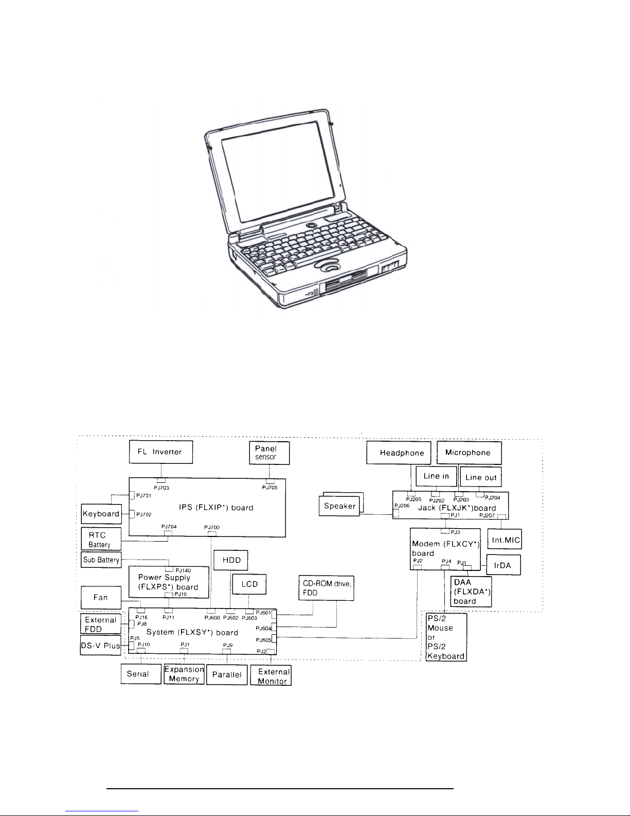
The 710CDT/720CDT Personal Computer is shown in Figure 1-1 and their system configuration in Figure 1-2.
Figure 1-1 710CDT/720CDT personal computer
Figure 1-2 710CDT/720CDT system unit configuration
710CDT/720CDT
1-5
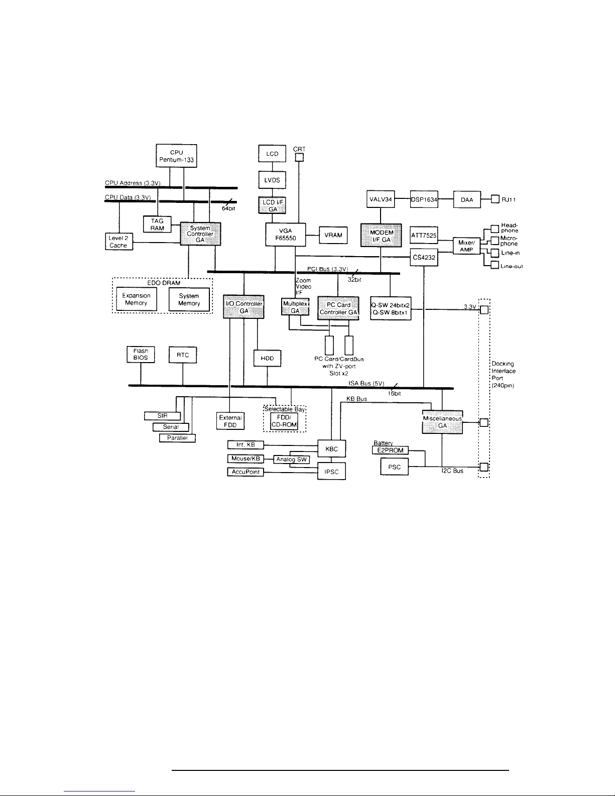
1.2 System Unit Block Diagram
The following figure shows a block diagram of the system unit.
The system board is composed of the following major components:
❑ Intel Pentium processor operating at 133 MHz and 2.9/3.3 volts. A math co-processor
and 16 KB cache memory are integrated into the processor.
❑ Level-2 cache memory
Data RAM:
- 256 KB
- Two 32K x 32-bit pipe-line burst synchronous SRAM chips
- 3.3 volt operation
- 8 ns access time
710CDT/720CDT
Figure 1-3 System board block diagram

1-6
Tag RAM:
- 32 KB (only 8 KB is used)
- One 32K x 8-bit asynchronous SRAM chip
- 3.3 volt operation
- 15 ns access time
The level-2 cache uses direct mapping, utilizing a write-through policy.
❑ Standard RAM
16 MB, eight 1M x 16-bit EDO DRAM chips
3.3 volt operation
No parity bit
60 ns access time
64-bit width data transfer
❑ BIOS ROM (Flash EEPROM)
256 KB, one 256K x 8-bit chip
- 128 KB are used for system BIOS
- 64 KB are used for VGA-BIOS
- 8 KB are used for plug and play data area
- 8 KB are used for password security
- 16 KB are used for boot strap
- 32 KB are reserved
5 volt operation
120 ns access time
8-bit width data transfer
❑ Optional memory
One expansion memory slot for 8, 16, 32, 64, and 128MB memory modules, which
consist of 1M x 16-bit chips (8, 16, 32MB) and 4M x 16-bit chips (64, 128MB).
EDO DRAM is used
3.3 volt operation
No parity bit
60 ns access time
64-bit width data transfer
❑ Video RAM
2 MB, four 256K x 16-bit EDO DRAM chips
5 volt operation
60 ns access time
❑ System controller Gate Array
This gate array has the following functions:
- CPU interface/control
- Level-2 cache memory control
- DRAM control
- PCI master/slave interface
- Write buffer (CPU-DRAM, CPU-PCI, PCI-DRAM)
710CDT/720CDT

1-7
- Prefetch buffer (PCI-DRAM)
- Two DMACs: 82C37 equivalent
- Two PICs: 82C59 equivalent
- One PIT: 82C54 equivalent
- Serial interrupt function
- Power management control
- Suspend/resume control
- CPU stop clock function
❑ I/O controller Gate Array
This gate array has the following functions:
- Two UARTs 16550A equivalent (one SIO is used for SIR)
- One FDC µPD765A equivalent
- One ECP supported parallel port control
- ISA bus control
- PCI bus front end control
❑ Multiplex Gate Array
This gate array is a multiplexer for a ZV port.
❑ LCD interface Gate Array
This gate array controls data transfer between a VGA controller and LVDS.
❑ PC Card Controller Gate Array
This gate array has the following functions:
- PC card control
- CardBus control
- ZV port support (multiplex gate array control)
❑ Miscellaneous Gate Array
This gate array has the following functions:
- Communication control
Communication with KBC
I2C bus interface
Communication with power supply
Communication with Desk Station V Plus
Communication with EEPROM
Communication register set
- PWM control
Beep volume
- Speaker control
- Universal I/O port
- Q-SW control
❑ Modem interface Gate Array
This gate array controls modem interface LSIs.
710CDT/720CDT

1-8
❑ Video Controller
Chips & Technology F65550 is used.
The video controller controls the internal LCD and an external CRT.
❑ Keyboard Controller (KBC)
One M38802M4 chip is used.
The KBC includes the keyboard scan controller and keyboard interface controller.
The KBC controls the internal keyboard, external keyboard, AccuPoint, or PS/2
mouse.
❑ AccuPoint Controller (IPSC)
One KPAAC0062A chip is used.
The controller provides simultaneous control of both the AccuPoint and a PS/2 mouse.
❑ Real Time Clock (RTC)
One T9934 chip is used.
The T9934 has 128 bytes of memory. Fourteen (14) bytes are used for the calendar and
clock, and the remaining 114 bytes are used for system configuration data.
710CDT/720CDT
1-9
1.3 3.5-inch Floppy Disk Drive
The removable 3.5-inch FDD is a thin, high-performance, reliable drive that supports 720-KB
(formatted) 2DD and 1.44-MB (formatted) 2HD disks. When a CD-ROM is installed in the
Selectable Bay, an FDD attachment can be used to connect the FDD to the external FDD port.
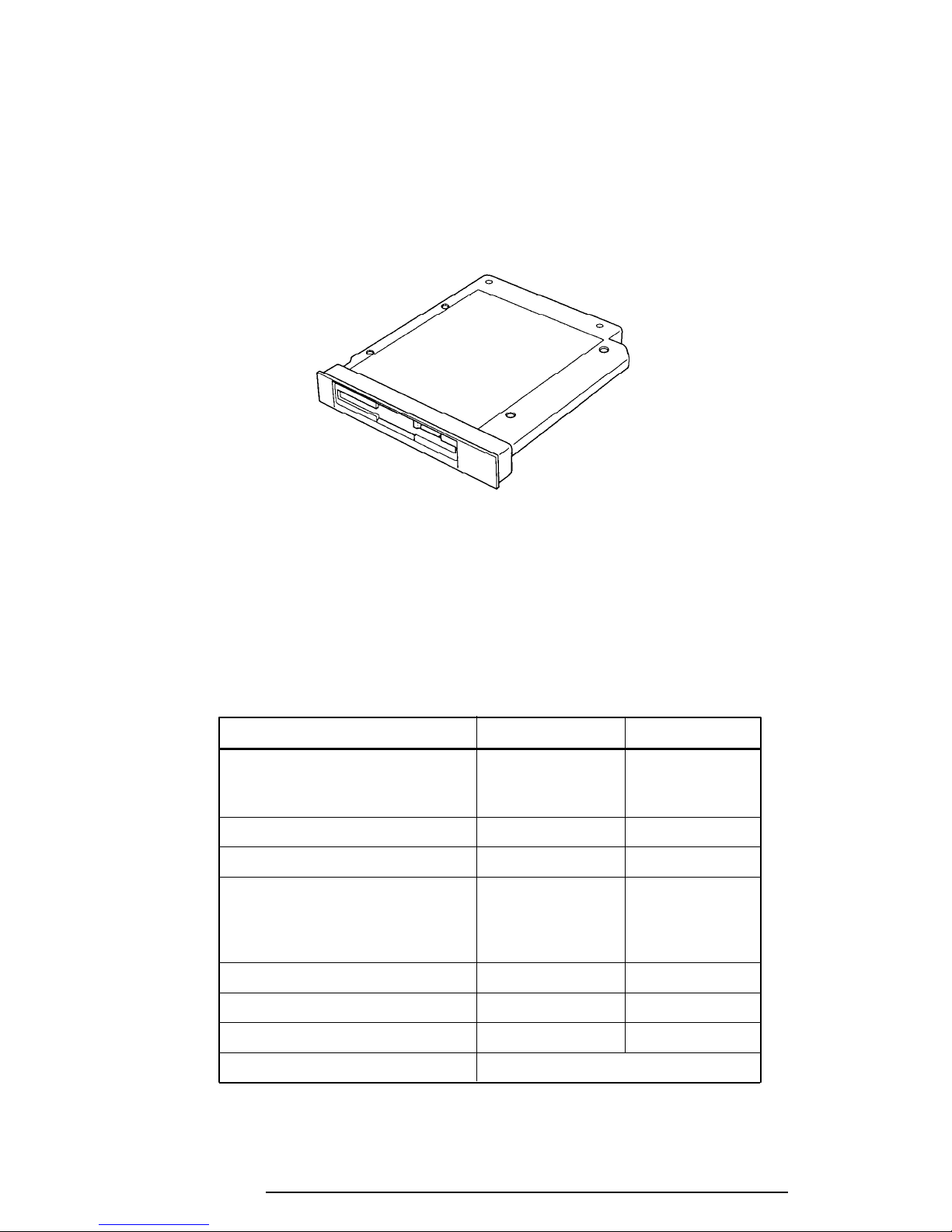
The FDD is shown in Figure 1-4, and its specifications are listed in Table 1-1.
Figure 1-4 3.5-inch FDD
Table 1-1 3.5-inch FDD specifications
Item 2-MB mode 1-MB mode
Storage capacity (KB)
Unformatted 2,000 1,000
Formatted 1,440 720
Number of heads 2 2
Number of cylinders 80 80
Access time (ms)
Track to track 3 3
Average 181 181
Head settling time 15 15
Recording track density (tpi) 135 135
Data transfer rate (Kbps) 500 250
Rotation speed (rpm) 300 300
Recording method Modified Frequency Modulation (MFM)
710CDT/720CDT
1-10
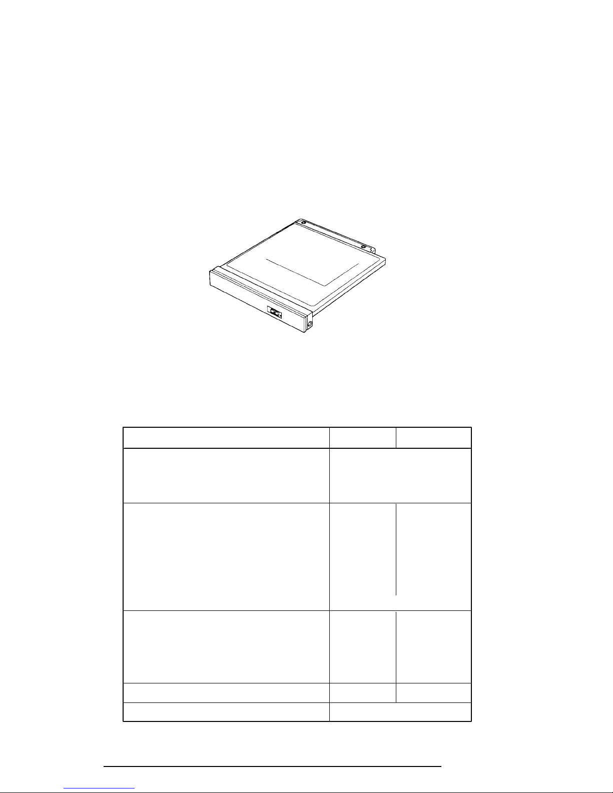
1.4 2.5-inch Hard Disk Drive
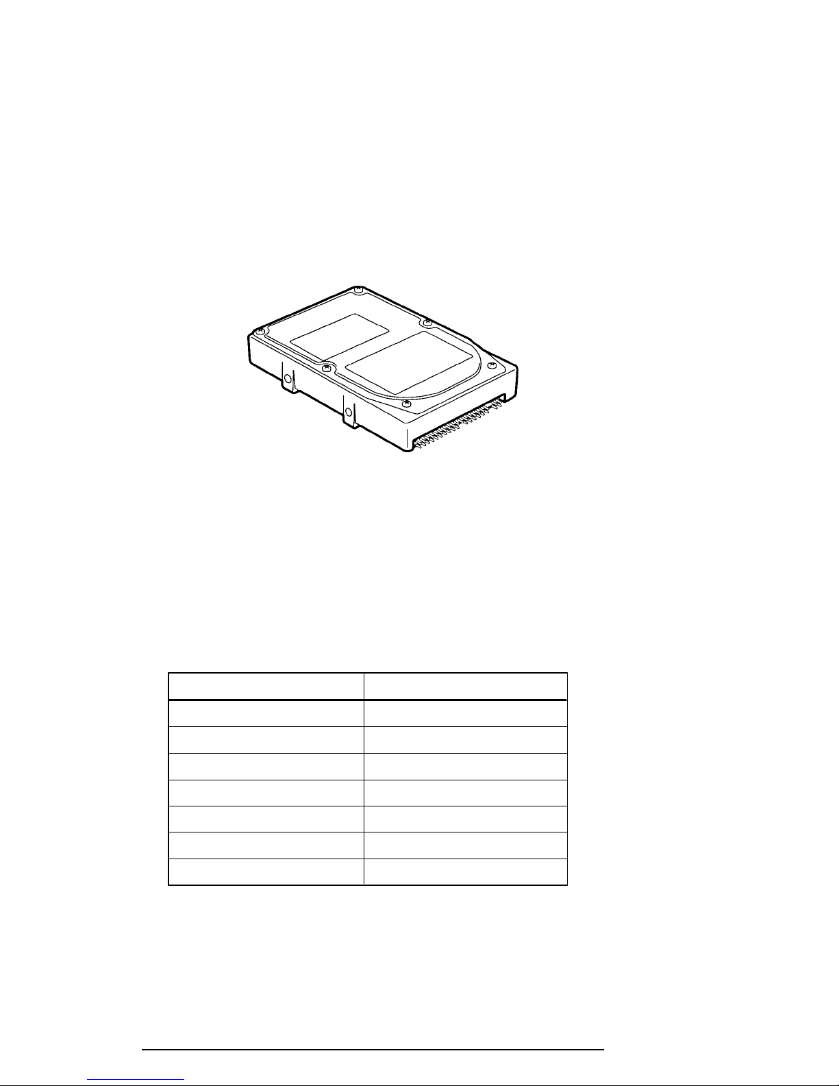
The removable HDD is a random access, nonvolatile storage device. It has a non-removable
2.5-inch magnetic disk and mini-winchester type magnetic heads.
710CDT/720CDT supports a 1.13 GB HDD.
The HDD is shown in Figure 1-5, and its specifications are listed in Table 1-2.
Figure 1-5 2.5-inch HDD
Table 1-2 2.5-inch HDD specifications
Items (MK2720FC)
Storage capacity (GB) 1,216,954,368
Cylinders 2,358
Heads 16
Sectors 63
Bytes per sector 512
Rotation speed (rpm) 4,200
Recording method 8-9 RLL
710CDT/720CDT
1-11
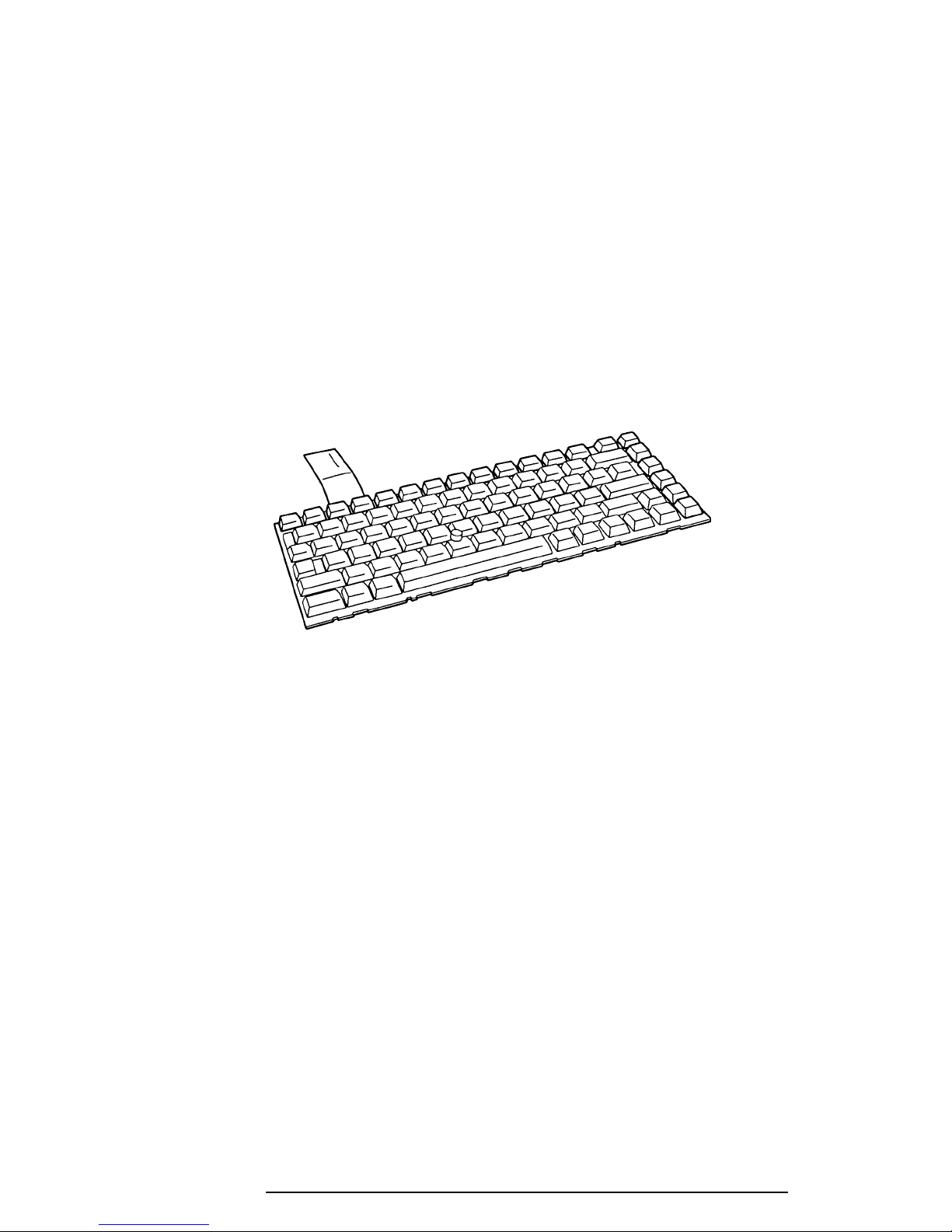
1.5 Keyboard
The 82-key (USA) or 84-key (European) keyboard is mounted on the system unit. The
keyboard is connected to the keyboard controller on the system board through a 25-pin flat
cable.
The 710CDT/720CDT AccuPoint pointer control stick, located in the center of the keyboard,
provides convenient control of the cursor without requiring desk space for a mouse. The
keyboard is shown in Figure 1-6.
See Appendix E for optional keyboard configurations.
Figure 1-6 Keyboard
710CDT/720CDT
1-12
1.6 CD-ROM Drive
The removable CD-ROM drive accommodates both 12 cm (4.72-inch) or 8 cm (3.15-inch)
CDs. It provides high-performance, six-speed play, and reads 900KB per second. The drive
supports the following formats: Red-Book, Yellow-Book, CD-ROM XA, Photo CD, CDBridge, CD-I, and CD Plus.
The CD-ROM drive is shown in Figure 1-7 and its specifications listed in Table 1-3.
Figure 1-7 CD-ROM drive
Table 1-3 CD-ROM drive specifications
Item 1 x mode 6 x mode
Data Capacity (bytes/block)
Mode 1 2,048
Mode 2 2,336
Transfer Rate
Sustained Block transfer speed (blocks/s) 75 450
Sustained Data transfer speed (kbytes/s)
Mode 1 150 900
Mode 2 171 1,026
ATAPI Burst (Mbytes/s) 8.33 (PIO mode 2)
Access time (ms)
Average Random Access 350 190
Average Random Seek 230 160
Average Full Stroke Access 500 330
Rotation speed (rpm) 200 to 530 1,200 to 3,180
Data Buffer Capacity (Kbytes) 128
710CDT/720CDT
1-13
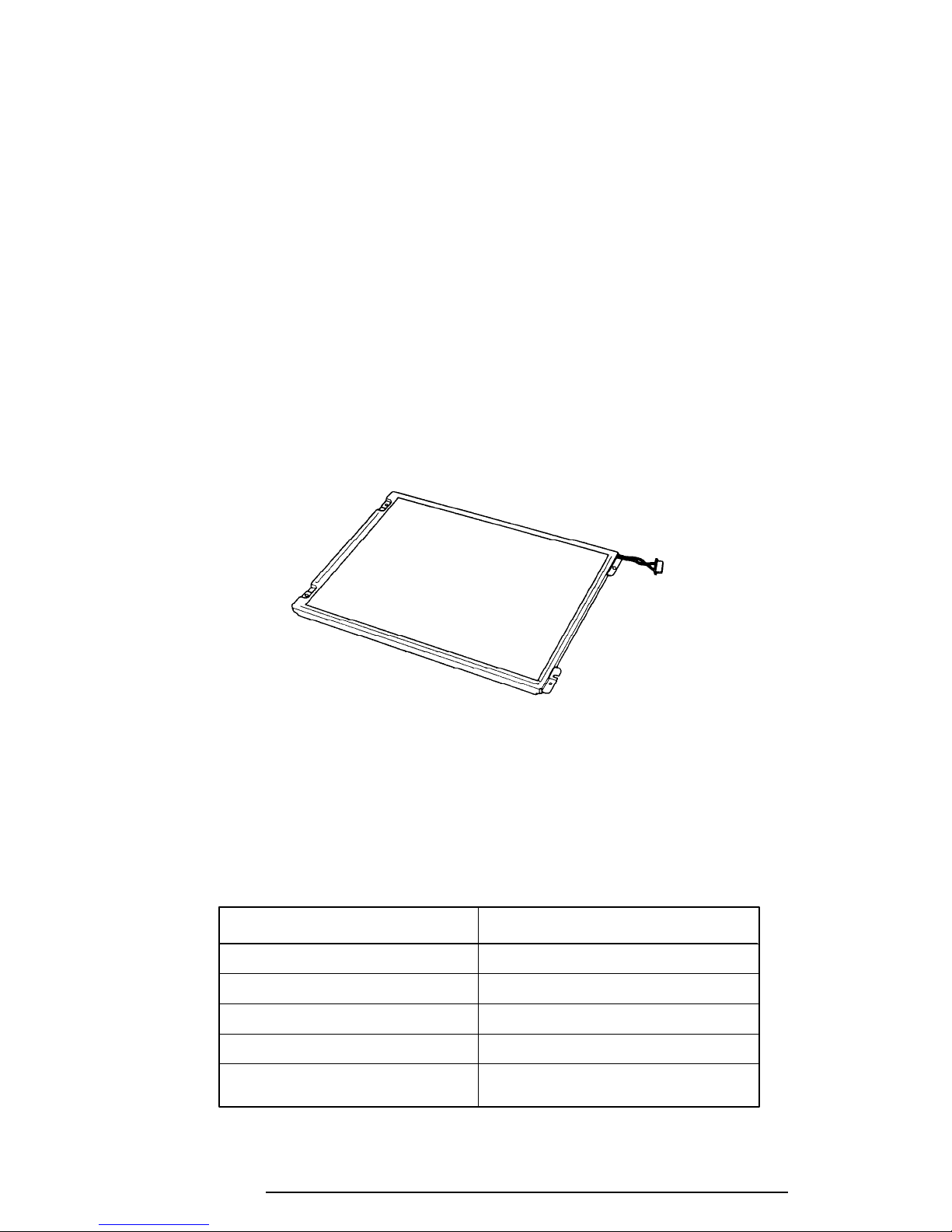
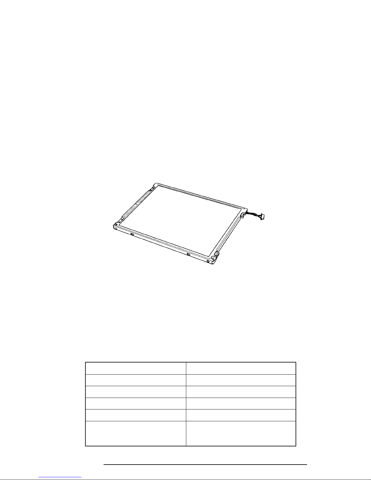
1.7 710CDT TFT Color LCD
The 710CDT TFT Color Liquid Crystal Display (LCD) contains an LCD module, a Fluorescent Lamp (FL), and an FL inverter board.
1.7.1 710CDT TFT Color LCD Module
The 710CDT TFT color LCD is backlit supporting 800 x 600 pixels with a built-in display
controller. The controller incorporates functions of the Video Graphics Array (VGA) and
Super VGA (SVGA) for external displays.
The display controller is F65550, and enables an LCD to display a maximum 16 million
colors.
The TFT LCD is shown in Figure 1-8, and its specifications are listed in Table 1-4.
Figure 1-8 710CDT color LCD
Table 1-4 710CDT color LCD specifications
Item Specifications
Number of Pixels (pixels) 800 x 600
Dot pitch (mm) 0.3075 x 0.075
Display area (mm) 246 (W) x 184.5 (H)
Contrast 100:1
FL current (mA) 6.0/4.0/3.6/2.4*
(Bright/Semi-bright)
710CDT/720CDT
1-14
* NOTE: FL currents at power on are:
Bright Semi-bright
AC adapter connected 6 mA 3.6 mA
AC adapter not connected 4 mA 2.4 mA
(The settings at power on do not change even if the AC adapter
connection changes.)
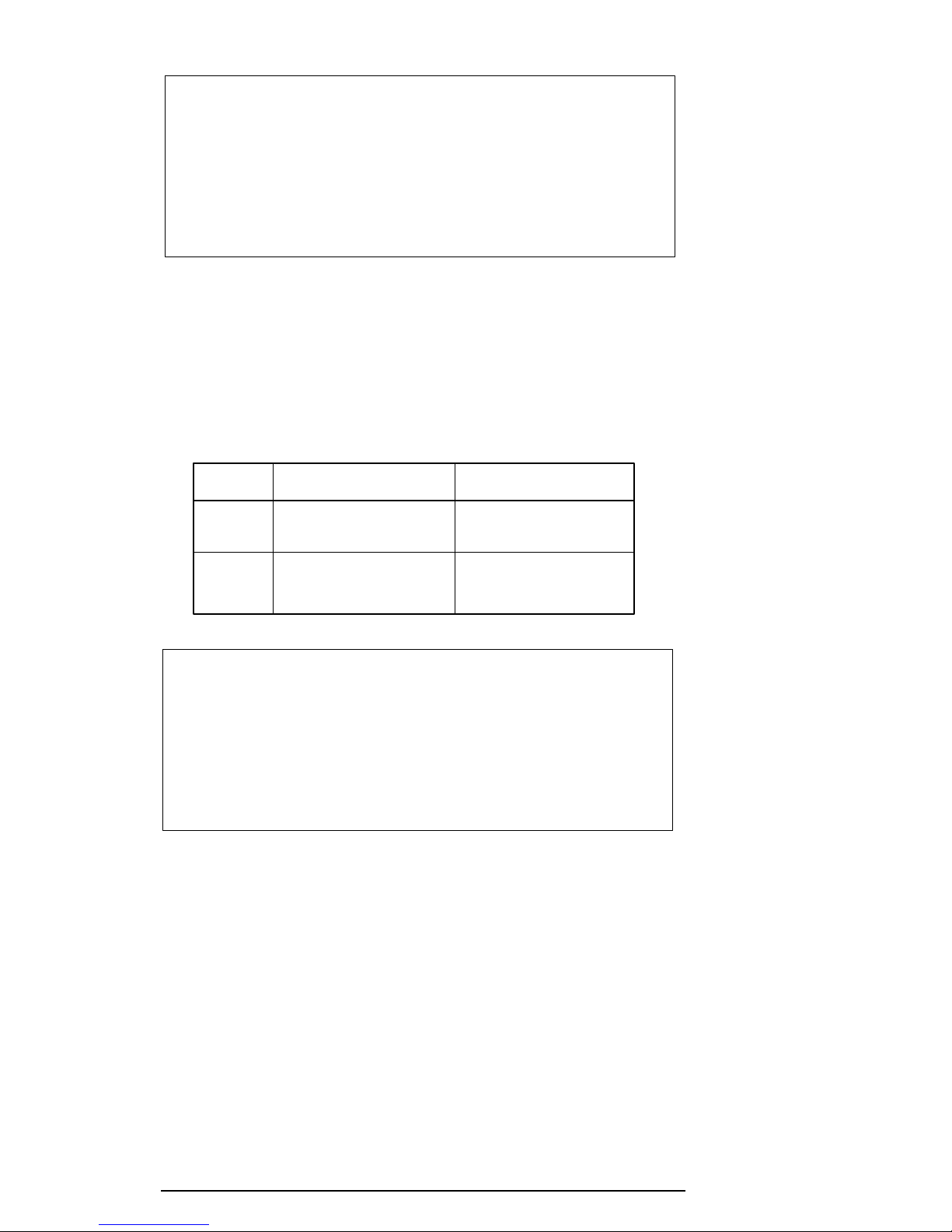
1.7.2 Fluorescent Lamp (FL) Inverter Board for 710CDT
The FL inverter board supplies a high frequency current to light the LCD’s Fluorescent Lamp.
Specifications for the FL inverter are listed in Table 1-5.
Table 1-5 FL inverter board specifications for 710CDT color LCD
Status Item Specifications
Input Voltage (V) 4 to 5.5
Power (W) 4.8
Output Voltage (Vrms) 1,100
Current (mA) 6.0/4.0/3.6/2.4*
*NOTE: FL currents at power on are:
Bright Semi-bright
AC adapter connected 6 mA 3.6 mA
AC adapter not connected 4 mA 2.4 mA
(The settings at power on do not change even if the AC adapter
connection changes.)
710CDT/720CDT
1-15
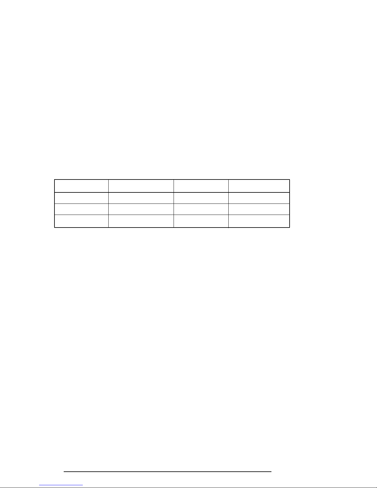
1.8 720CDT TFT Color LCD
The 720CDT TFT Color Liquid Crystal Display (LCD) contains an LCD module, a Fluorescent Lamp (FL), and an FL inverter board.
1.8.1 720CDT TFT Color LCD Module
The 720CDT TFT color LCD supports 1024 x 768 pixels and includes a built-in display
controller. The controller incorporates the functions of a Video Graphics Array (VGA) and
Super VGA (SVGA) for external displays.
The display controller is F65550, and enables an LCD to display a maximum 64K colors.
The TFT LCD is shown in Figure 1-9, and its specifications are listed in Table 1-6.
Figure 1-9 720CDT color LCD
Table 1-6 720CDT color LCD specifications
Item Specifications
Number of Pixels (pixels) 1024 x 768
Dot pitch (mm) 0.24 x 0.24
Display area (mm) 245.76 (W) x 184.32 (H)
Contrast 150:1
FL current (mA) 6.0/4.0/3.6/2.4*
(Bright/Semi-bright)
710CDT/720CDT
1-16
* NOTE: FL currents at power on are:
Bright Semi-bright
AC adapter connected 6 mA 3.6 mA
AC adapter not connected 4 mA 2.4 mA
(The settings at power on do not change even if the AC adapter
connection changes.)
1.8.2 Fluorescent Lamp (FL) Inverter Board for 720CDT
The FL inverter board supplies a high frequency current to light the LCD’s Fluorescent Lamp.
Specifications for the FL inverter are listed in Table 1-7.
Table 1-7 FL inverter board specifications for 720CDT color LCD
Status Item Specifications
Input Voltage (V) 4 to 5.5
Power (W) 4.8
Output Voltage (Vrms) 1,100
Current (mA) 6.0/4.0/3.6/2.4*
*NOTE: FL currents at power on are:
Bright Semi-bright
AC adapter connected 6 mA 3.6 mA
AC adapter not connected 4 mA 2.4 mA
(The settings at power on do not change even if the AC adapter
connection changes.)
710CDT/720CDT

1-17
1.9 Power Supply
The Power Supply sends four variations of voltages to the system board, has one microprocessor, and operates at 2 MHz. It offers the following features:
1. Determines if the AC adapter or battery is connected to the computer.
2. Detects DC output and circuit malfunctions.
3. Controls the Battery Capacity icon and DC In icon.
4. Turns the battery charging system on and off, and detects a fully charged battery.
5. Determines if the power can be turned on and off.
6. Provides more accurate detection of a low battery.
7. Calculates remaining battery capacity.
8. Detects Ring Indicator (RI) signal for the Auto Power On function.
The power supply output ratings are specified in Table 1-8.
Table 1-8 Power supply board output ratings
Use Name voltage tolerance current Ripple
System logic, FDD, HDD B5V +5.0 ±5 3,400 100
Display panel, FL and
PC card
CPU, RAM, PC card B3V +3.3 ±5 3,800 60
Flash ROM, PC card B12V +12.0 ±5 100 240
System logic MCV +5.0 ±5 5 100
DC Regulation Maximum
(V) (%) (mA) (mV)
710CDT/720CDT
1-18
1.10 Batteries
The computer has three types of batteries:
Main battery pack
❑
❑ Backup battery
❑ Real Time Clock (RTC) battery
The removable main battery pack is the computer’s main power source when the AC adapter is
not attached. The backup and main batteries maintain the current state of the computer when
AutoResume is enabled.
Battery specifications are listed in Table 1-9.
Table 1-9 Battery specifications
Battery name Material Output voltage Capacity
Main battery Lithium-Ion 10.8 V 5,600 mAh
Backup battery Nickel Metal Hydride 7.2 V 35 mAh
RTC battery Nickel Metal Hydride 3.6 V 35 mAh
1.10.1 Main Battery
Battery Charging Control
Battery charging is controlled by a microprocessor that is mounted on the power supply. The
microprocessor controls whether the charge is on or off, and detects a full charge when the AC
adapter and battery are attached to the computer. The system charges the battery using a quick
charge or trickle charge.
❑ Quick Battery Charge
When the AC adapter is attached, there are two types of quick charge: quick charge 1
when the system is powered off, and quick charge 2 when the system is powered on.
710CDT/720CDT

1-19
Table 1-10 Time required for quick charges
Status Charging time
Quick charge 1 4 hours
(power off)
Quick charge 2 4.5 to 12.5 hours
(power on)
NOTES 1: The time required for quick charge 2 is affected by the amount of
power the system is consuming. Use of the fluorescent lamp and
frequent disk access diverts power and lengthens the charge time.
2: Using quick charge 1, the system CPU automatically stops the charge
after five hours and 30 minutes regardless of the condition of the battery.
If one of the following occurs, the battery quick charge process stops.
1. The battery becomes fully charged.
2. The AC adapter or battery is removed.
3. The battery or output voltage is abnormal.
❑ Trickle Battery Charge
When the main battery is fully charged and the AC adapter is attached, the microprocessor automatically changes quick charge 1 or 2 to trickle charge.
❑ Detection of full charge
A full charge is detected only when the battery is charging at quick charge and is
detected under any of the following conditions:
1. The current in the battery charging circuit drops under the fixed limit.
2. The charging time exceeds the fixed limit.
3. The battery’s temperature is over 60°C.
710CDT/720CDT
1-20
1.10.2 Backup Battery
The backup battery maintains data for AutoResume. The power source used to back up the
AutoResume data is determined by the following priority:
AC adapter > Main battery > Backup battery
The backup battery is charged by the main battery or AC adapter. Table 1-11 lists the charging
time and data preservation period of the backup battery.
Table 1-11 Backup battery charging/data preservation time
Status Time
Charging Time 7 hours with AC adapter
14 hours without AC adapter
Data preservation period (full charge) 2 hours
1.10.3 RTC Battery
The RTC battery provides power to keep the current date, time and other setup information in
memory while the computer is turned off. Table 1-12 lists the charging time and data preservation period for the RTC battery.
Table 1-12 RTC battery charging/data preservation time
Status Time
Charging Time (Power On) 40 hours
Data preservation period (full charge) 1 month
710CDT/720CDT

2-1
2.1 Troubleshooting
Chapter 2 describes how to determine if a Field Replaceable Unit (FRU) in the computer is
causing it to malfunction. FRUs covered include the:
1. System (FLXSY*) Board 7. Floppy Disk Drive
2. Modem (FLXCY*) Board 8. Hard Disk Drive
3. Jack (FLXJK*) Board 9. CD-ROM Drive
4. IPS (FLXIP*) Board 10. Keyboard
5. Power Supply (FSTPS*) Board 11. Display
6. DAA (FLXDA*) Board
NOTE: The DAA (FLXDA*) Board is standard equipment in Canada and the
United States, and an option in Europe.
The Diagnostics Disk operations are described in Chapter 3 and detailed replacement procedures in Chapter 4.
The following tools are necessary for implementing the troubleshooting procedures:
1. Diagnostics Disk
2. Phillips screwdriver (2 mm)
3. Toshiba MS-DOS system disk(s)
(You must install the following onto the disk: SYS.COM, FORMAT.COM,
FDISK.COM and FDISK.EXE)
4. A 2DD or 2HD formatted work disk used for floppy disk drive testing
5. Cleaning kit for floppy disk drive troubleshooting
6. Printer port LED
7. Printer wraparound connector
8. Serial port wraparound connector
9. PC card wraparound card
10. Multimeter
11. External monitor
12. PS/2 or compatible keyboard
13. PS/2 or compatible mouse
14. Multimedia sound system with line-in and line-out ports
15. Headphone
16. Microphone
17. Speakers with amplifier
18. External FDD attachment
19. Lens cleaner for CD-ROM laser pickup lens
20. Toshiba-EMI Test Disc TDY-03 for CD-ROM Drive
710CDT/720CDT
2-2
2.2 Troubleshooting Flowchart
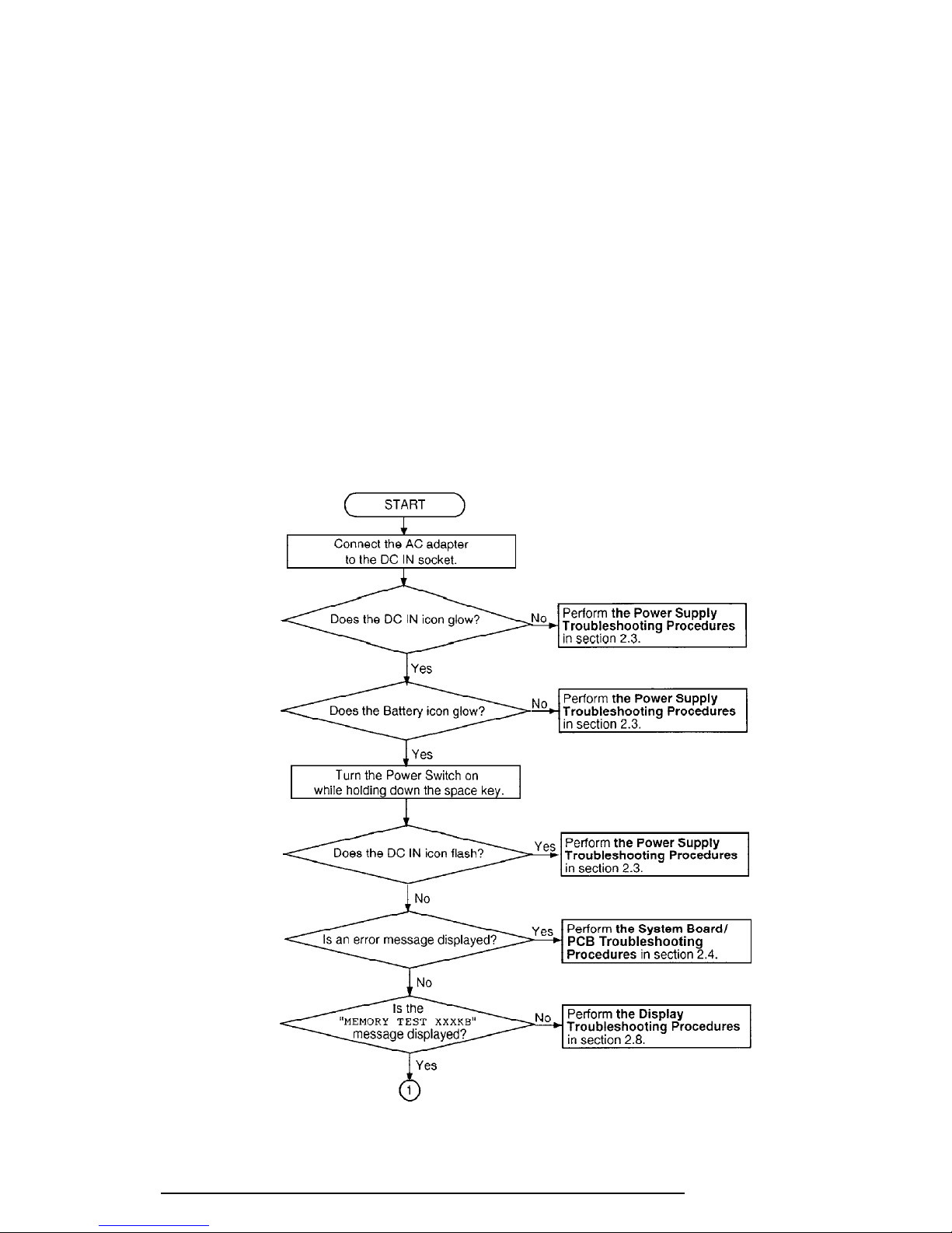
Use the flowchart shown in Figure 2-1 as a guide to determine which troubleshooting procedures to execute. Before proceeding through the flowchart steps:
❑ Ask the user if a password is registered and, if it is, ask him or her to enter the pass-
word. If the user has forgotten the password, connect the printer port wraparound
board (F31PRT), then turn the POWER switch on. The computer will override the
password function by erasing the current password.
❑ Verify with the customer that Toshiba MS-DOS or Toshiba Windows
®
95 is installed
on the hard disk. Non-Toshiba operating systems can cause the computer to malfunction.
❑ Make sure all optional equipment is disconnected from the computer.
❑ Make sure the floppy disk drive is empty.
Figure 2-1 Troubleshooting flowchart (1/2)
710CDT/720CDT
2-3
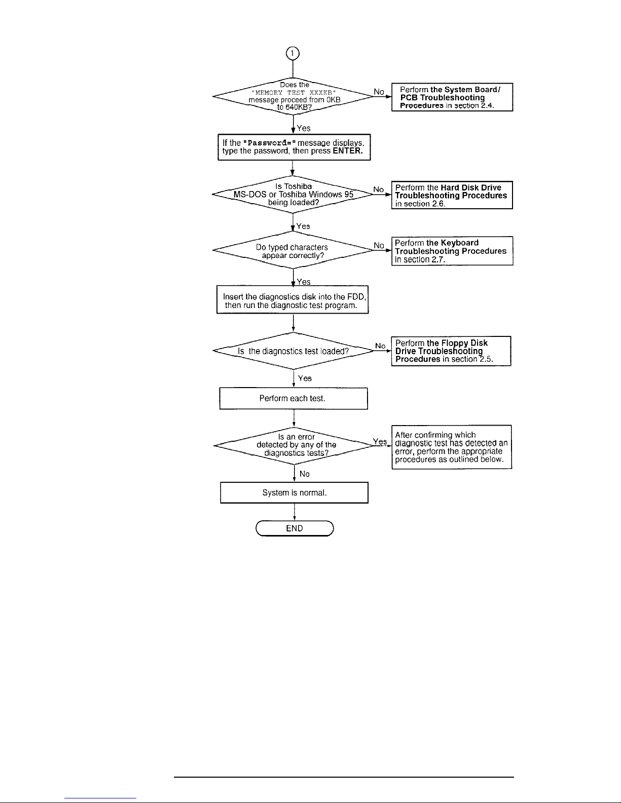
If the diagnostics program cannot detect an error, the problem may be intermittent. The Running Test program should be executed several times in order to isolate the problem.
Check the Log Utilities function to confirm which diagnostic test detected an error(s), then
perform the appropriate troubleshooting procedures as follows:
1. If an error is detected on the system test, memory test, display test, ASYNC test,
printer test, expansion test, sound test, or real timer test, execute the system board/
PCB procedures outlined in Section 2.4.
2. If an error is detected on the floppy disk test, execute the floppy disk drive troubleshooting procedures outlined in Section 2.5.
710CDT/720CDT
Figure 2-1 Troubleshooting flowchart (2/2)

2-4
3. If an error is detected on the hard disk test, perform the hard disk drive
troubleshooting procedures outlined in Section 2.6.
4. If an error is detected on the keyboard test, execute the keyboard troubleshooting
procedures outlined in Section 2.7.
5. If an error is detected on the display test, execute the display troubleshooting
procedures outlined in Section 2.8.
6. If an error is detected on the CD-ROM test, execute the CD-ROM drive troubleshooting procedures outlined in Section 2.9.
7. If an error is detected on the modem test, execute the modem troubleshooting
procedures outlined in Section 2.10.
710CDT/720CDT

2-5
2.3 Power Supply Troubleshooting
The power supply controls many functions and components. To determine if the power supply
is functioning properly, start with Procedure 1 and continue with other procedures as
instructed. The procedures described in this section are:
Procedure 1: Power Status Check
Procedure 2: Error Code Check
Procedure 3: Connection Check
Procedure 4: Quick Charge Check
Procedure 5: Replacement Check
Procedure 1 Power Status Check
The following icons indicate the power supply status:
❑ Battery icon
❑ DC IN icon
The power supply controller displays the power supply status using the Battery and the DC IN
icons as shown in the following tables.
Table 2-1 Battery icon
Battery icon Power supply status
Lights yellow Quick charge.
Lights green Battery has a full charge and the AC adapter is
connected.
Blinks yellow The battery level becomes low while operating the
(even intervals) computer on battery power.
Flashes yellow The power switch is pressed on when the battery
level is low.
Doesn't light Any condition other than those above.
*1
AutoResume Off will be executed soon.
*2
AutoResume Off has already been executed.
*2
*1
710CDT/720CDT
2-6
Table 2-2 DC IN icon
DC IN icon Power supply status
Lights green DC power is being supplied from the AC adapter,
or Desk Station V Plus.
Blinks green Power supply malfunction.
Doesn't light Any condition other than those above.
*3
When the power supply controller detects a malfunction, the DC IN icon
*3
blinks and an error code is displayed.
To check the power supply status, install a battery pack and connect an AC adapter.
Check 1 If the DC IN icon flashes yellow, go to Procedure 2.
Check 2 If the DC IN icon does not light, go to Procedure 3.
Check 3 If the Battery icon does not light yellow or green, go to Procedure 4.
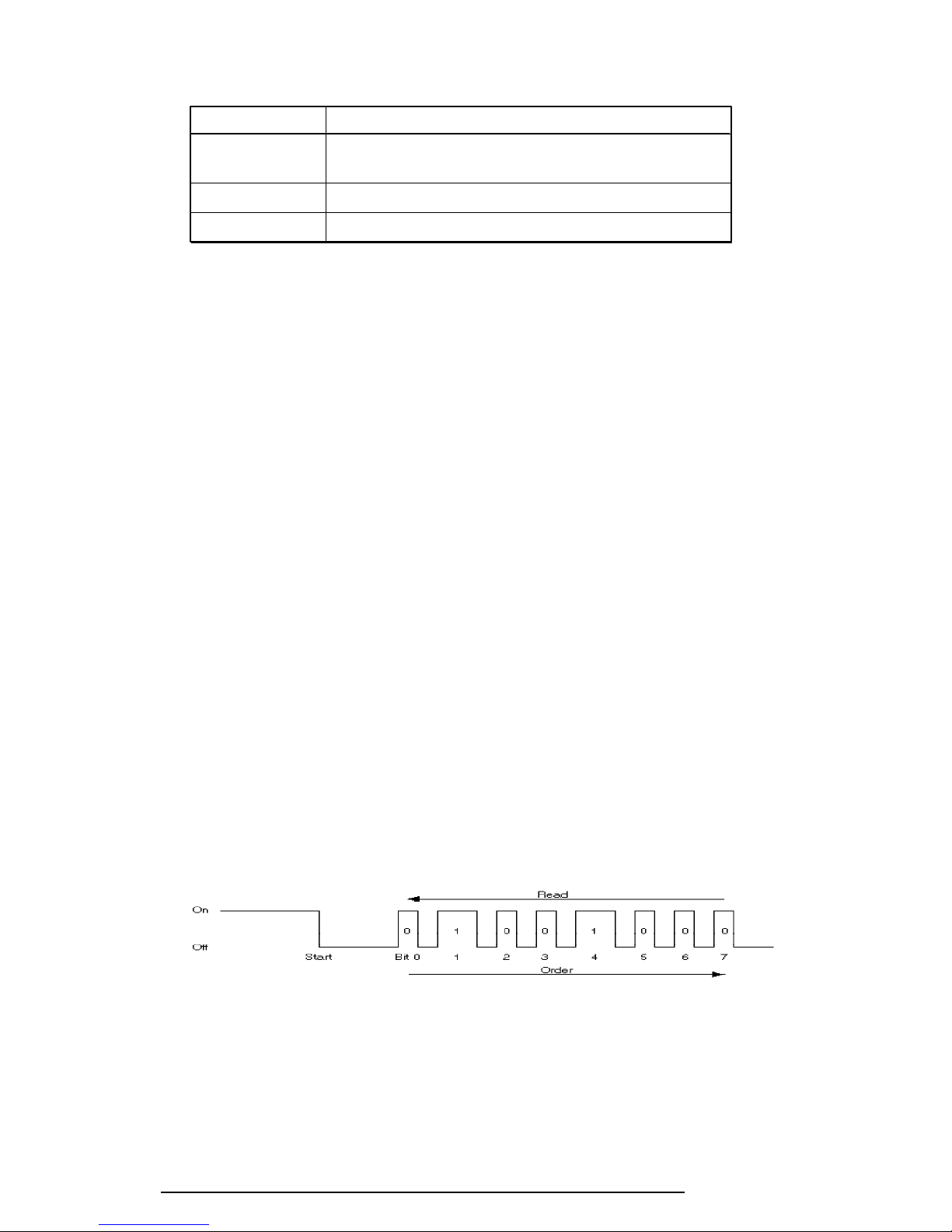
Procedure 2 Error Code Check
If the microprocessor detects a malfunction, the DC IN icon blinks yellow. The blink pattern
indicates an error, as shown below.
❑ Start Off for 2 seconds
❑ Error code (8 bit)
"1" On for one second
"0" On for a half second
Interval between data bits Off for a half second
An error code begins with the least significant digit.
Example: Error code 12h (error codes are displayed in a hexadecimal format.)
Check 1 Convert the DC IN icon blink pattern into the hexadecimal error code and compare
it to the following tables.
710CDT/720CDT
2-7
❑ DC power supplied through AC adapter or Desk Station V Plus
Error code Meaning
01h AC Adapter output is over the maximum allowed limit.
02h Desk Station V Plus output is over the maximum allowed
limit.
04h Current from the DC power supply is over the maximum
allowed limit.
05h Current from the DC power supply is over the maximum
allowed limit when there is no load.
❑ Battery pack
Error code Meaning
10h Battery voltage is over the maximum allowed limit.
11h Battery charge current is over the maximum allowed limit.
12h Battery discharge current is over the maximum allowed
limit when there is no load.
13h Battery charge current is over the maximum allowed limit.
❑ B5V, VCC power supply output
Error code Meaning
20h B5V voltage is over the maximum allowed limit.
21h B5V voltage is below the minimum allowed limit.
22h B5V or VCC does not start up when the power supply is
turned on.
23h VCC voltage is below the minimum allowed limit.
24h During suspend, B5V voltage is below the minimum
allowed limit.
❑ B3V output
Error code Meaning
30h B3V voltage is over the maximum allowed limit.
31h B3V voltage is below the minimum allowed limit.
32h B3V does not start when the power supply is turned on.
33h B3V is below the minimum allowed limit during suspend.
710CDT/720CDT

2-8
❑ B12V Output
Error code Meaning
40h B12V voltage is over the maximum allowed limit.
41h B12V voltage is below the minimum allowed limit.
42h B12V does not start when the power supply is turned on.
43h B12V is below the minimum allowed limit during suspend.
❑ Power supply microcontroller
Error code Meaning
50h Firmware or program error.
❑ Environmental condition
Error code Meaning
80h CPU temperature is outside the allowable range.
88h The CPU overheats, the system enters resume mode and
automatically shuts down.
Check 2 If error code 01h displays:
❑ Make sure the AC adapter and AC power cord are firmly plugged into the
DC IN 15 V socket and wall outlet. If these cables are connected correctly,
go to the following step:
❑ Connect a new AC adapter. If the error still exists, go to Procedure 5.
Check 3 In error code 02h displays:
❑ Make sure the Desk Station V Plus is firmly connected to the computer's
docking interface port. If this port is connected correctly, go to the following step:
❑ Visually check the connector to make sure that no pins are bent. If a pin(s) is
bent, go to Chapter 4, Replacement Procedures. If the connector is not
physically damaged, go to the following step:
❑ Check the Desk Station V Plus for malfunctions. Refer to the Desk Station V
Plus maintenance manual for details. If the error still exists, go to
Procedure 5.
710CDT/720CDT
2-9
Check 4 In error code 10h displays:
❑ Make sure the battery pack is correctly installed in the computer. If the
battery pack is correctly installed, go to the following step:
❑ Replace the battery pack with a new one. If the error still exists, go to
Procedure 5.
Check 5 When 80h is displayed, it indicates that the CPU temperature is outside the allow-
able operating range. Perform the following steps:
❑ Leave the computer in an area that is room temperature until the CPU's
internal temperature is within the allowable operating range.
❑ If the error still exists, go to Procedure 5.
Check 6 When 88h is displayed, it indicates that the CPU temperature is too high. In this
case, the computer automatically enters resume mode and shuts down.
❑ Leave the computer off until the DC IN icon stops blinking. It is recom-
mended that you leave the computer off until its interior reaches room
temperature even though the DC IN icon stops blinking.
❑ If the error still exists, go to Procedure 5.
Check 7 For any other error, go to Procedure 5.
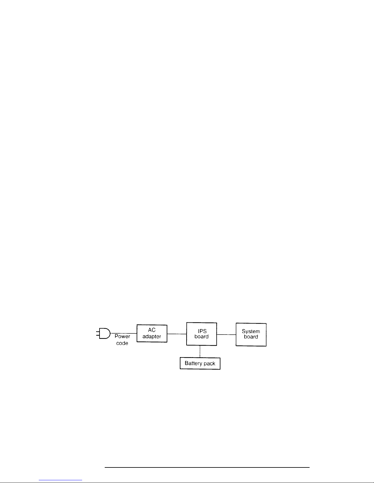
Procedure 3 Connection Check
The power supply wiring diagram is shown below:
Any of the connectors may be disconnected. Perform Check 1.
Check 1 Make sure the AC adapter's cable and AC power cord are firmly plugged into the
DC IN 15 V socket and wall outlet. If these cables are connected correctly, go to
Check 2.
710CDT/720CDT

2-10
Check 2 Connect a new AC adapter.
❑ If the DC IN icon does not glow green, go to Procedure 5.
❑ If the Battery icon does not glow orange, go to Check 3.
Check 3 Make sure the battery pack is installed correctly in the computer. If the battery is
properly installed, and the Battery icon still does not glow orange, go to Procedure
4.
Procedure 4 Quick Charge Check
The power supply may not be charging the battery pack. Perform the following procedures:
1. Reinstall the battery pack.
2. Attach the AC adapter and turn on the power. If the power does not come on, go to
Procedure 5.
3. Run the Diagnostic test and execute subtest 06 (Quick Charge) from the System test
as described in Chapter 3.
4. When the quick charge is complete, the diagnostics test displays the result code.
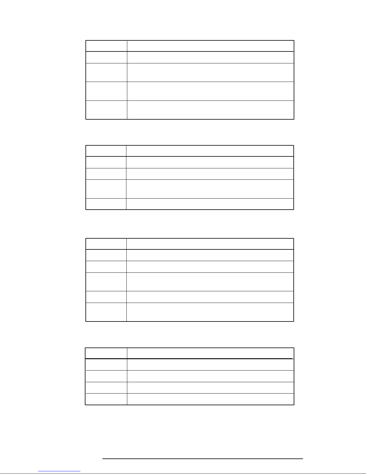
Check the result against the following table and perform any necessary check(s).
Result code Contents Check items
0 The battery is quick charging normally. Normal
1 The battery is fully charged. Normal
2 The AC adapter is not attached. Check 1
3 The AC adapter's output voltage is not Check 1
normal.
4 Battery is not installed. Check 2
5 The battery's output voltage is not Check 3
normal.
6 The battery's temperature is not normal. Check 4
7 A bad battery is installed. Check 2
8 Any other problem. Check 5
Check 1 Make sure the AC adapter's cable and AC power cord are firmly plugged into the
DC IN socket and wall outlet. If these cables are connected correctly, replace the
AC power cord and AC adapter.
710CDT/720CDT
 Loading...