

Page 1

Copyright:
(C)2000 by TOSHIBA CORPORATION. ALL RIGHTS RESERVED. Under the copyright laws, this manual cannot be
reproduced in any form without the prior written permission of TOSHIBA. No patent liability is assumed, however, with
respect to the use of the information contained herein.
First edition September 2000
NOTICE:
• No part of this document may be reproduced without the permission of TOSHIBA.
• Information in this document is subject to change without notice.
• If you have questions or find errors in this document, please contact our customer service center.
• TOSHIBA has no responsibility for the result by the operation in any situations.
• As for the difference between the keyboard described in this document and your keyboard, refer to the following
information.
Description in this document [Enter] = [Entr], [Entrée], [Intro]
[Ctrl] = [Control], [Strg]
[Esc] = [Echap]
[Ins] = [Insert], [Inser], [Einfg]
[Del] = [Delete], [Entf], [Suppr], [Supr]
[Break] = [Attn], [Untbr], [Inter]
Pentium is a registered trademark of Intel, Inc. in the United States.
MS, Microsoft, logo mark, MS-DOS, Windows, Windows NT, Windows 2000 are registered trademarks of Microsoft Corporation in the
United States and/or other countries.
Ethernet is a trademark of Fuji Xerox.
Adaptec and logo marks are registered trademarks of Adaptec, Inc. in the United States.
EZ-SCSI is a registered trademark of Adaptec, Inc. in the United States.
Novell, logo mark and NetWare are registered trademarks of Novell, Inc. in the United States.
MegaRAID, FlexRAID, RAIDExpress and PowerConsole are trademarks of American Megatrends, Inc. in the United States.
Other company, trademark and product names mentioned herein may be the trademarks or registered trademarks. The mark “TM”
and “®” are not written here.
Page 2

Preface
This manual consists of the following chapters:
Chapter 1 Server Setup TooL
Chapter 1. describes how to configure the hardware and start the Server Setup TooL.
Chapter 2 Setup
Chapter 2. describes how to use the Server Setup TooL.
Chapter 3 Utilities
Chapter 3. describes how to use the Toshiba Utilities.
Chapter 4 HW Diagnostics
Chapter 4. describes how to use the HW Diagnostics Program.
Chapter 5 Application
Chapter 5. describes how to install or uninstall the application.
Page 3

Contents
Preface
Contents
Chapter 1 Server Setup TooL
Checking the Accessories......................................................................................... 1
Starting SST.............................................................................................................. 1
Main Menu................................................................................................................ 5
Chapter 2 Setup
Setup Wizard.......................................................................................................... 6
Windows 2000 Quick Installation......................................................................... 12
Windows NT 4.0 Quick Installation...................................................................... 25
Windows NT 4.0 Manual Installation using SST................................................. 38
Windows 2000 Manual Installation without using SST...................................... 38
Windows NT 4.0 Manual Installation without using SST................................... 39
After Installation (Windows 2000)........................................................................ 41
After Installation (Windows NT 4.0)..................................................................... 42
Chapter 3 Utilities
How to start Utilities............................................................................................. 43
Utility Menu........................................................................................................... 46
Setup Support.................................................................................................... 46
HW Setup........................................................................................................... 49
Maintenance...................................................................................................... 49
Chapter 4 HW Diagnostics
About HW Diagnostics..................................................................................…... 50
Starting HW Diagnostics Program...................................................................... 50
Items of HW Diagnostics...................................................................................... 52
Log Utilities……................................................................................................... 68
System Configuration Display............................................................................. 70
Chapter 5 Application
Automatic Shutdown ........................................................................................... 73
Installing the TOSHIBA Display Power Save Driver........................................ 75
Installing the PCI Hot Plug Function ................................................................. 75
Page 4

Page 5

Chapter 1
Page 6

Page 7
Server Set up TooL
1
Checking the accessories
Checking the accessories
Before you start the Server Setup TooL (SST), ensure that the following accessories are
included:
- SST CD-ROM
-StartupDisk
- Server Setup TooL User's Guide (This guide)
- End-User License Agreement
Starting SST
NOTE: Depending on the optional equipment installed on the server, the SST may not work correctly.
Do not remove the Startup Disk or the SST CD-ROM while the SST is working.
Starting the server
1. Ensure that the monitor, keyboard, mouse, and all peripherals are connected
correctly.
2. Ensure that all power cables are connected to grounded AC outlets.
3. Switch on power to the monitor.
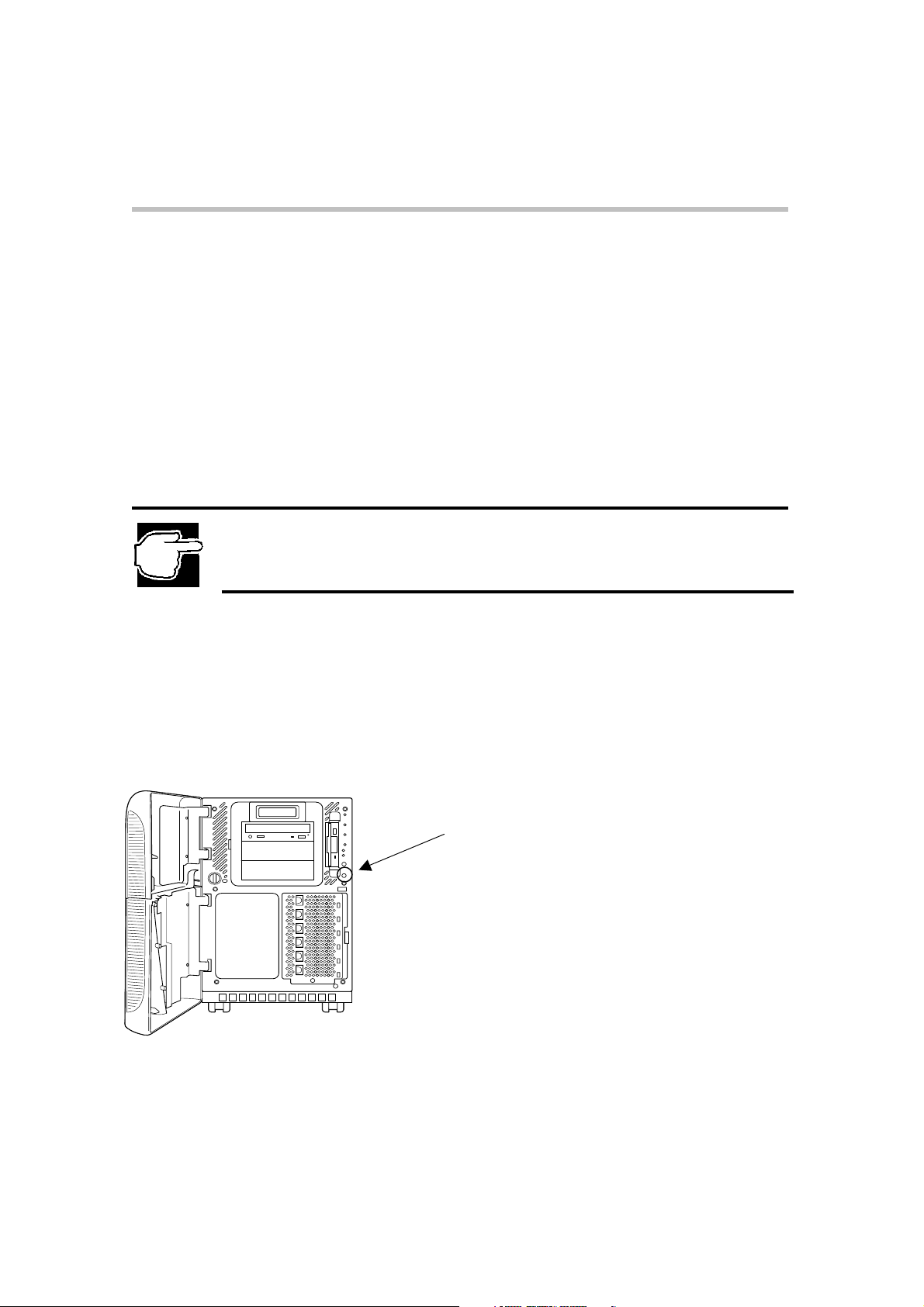
4. Insert the SST Startup Disk.
5. Turn on the Power switch at the front of the computer.
Power switch
MAGNIA7100 Front View
Page 8
Server Set up TooL
Starting the Server
6. When the following message appears:
"Please insert the Server Setup TooL CD, then press any key."
Insert the SST CD-ROM and press any key.
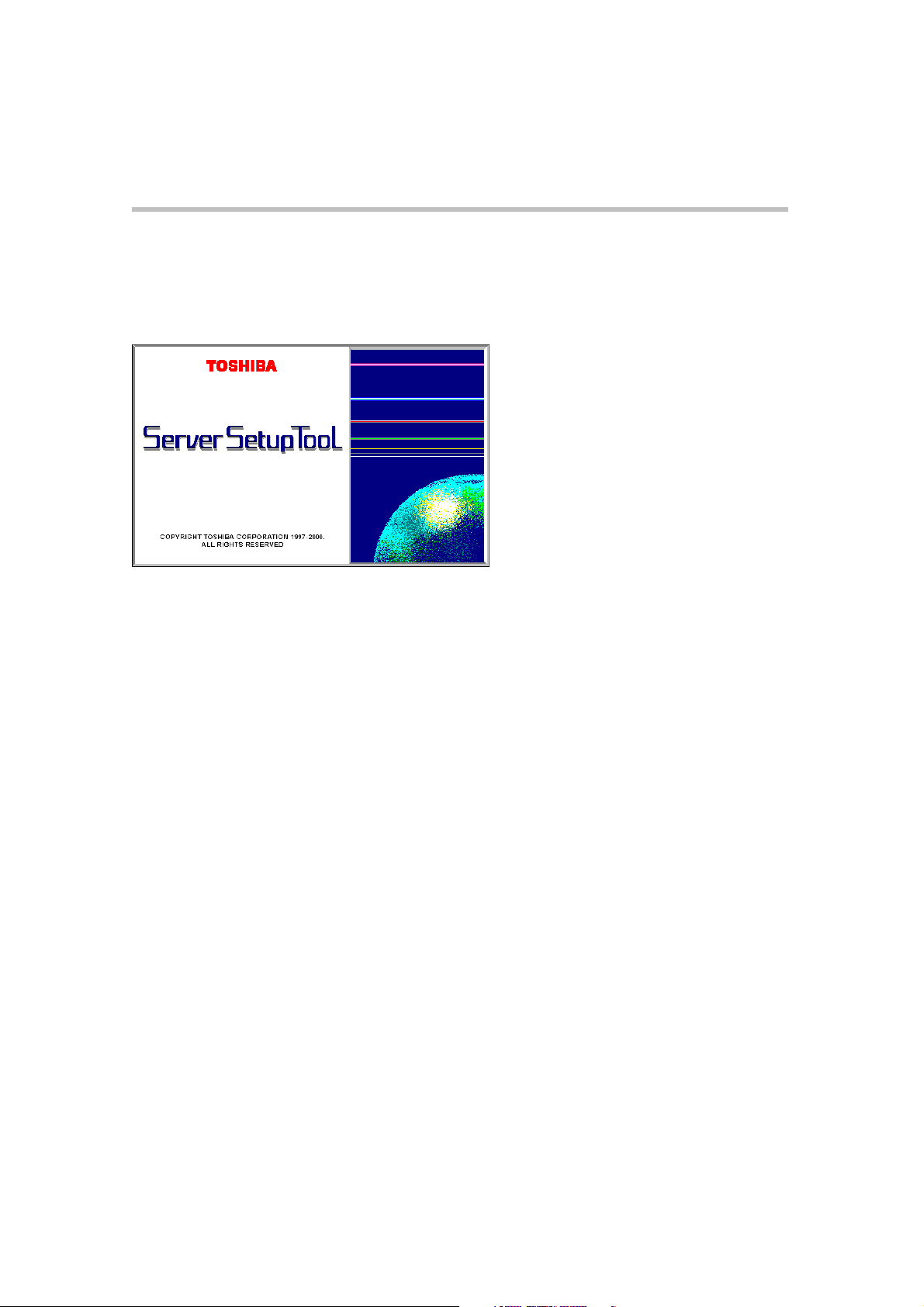
7. In a short time, the Start-up screen of the Toshiba 'Server Setup TooL' is displayed.
Start-up screen 'Server Setup
TooL'
2
Page 9
Server Set up TooL
Input Locale
3
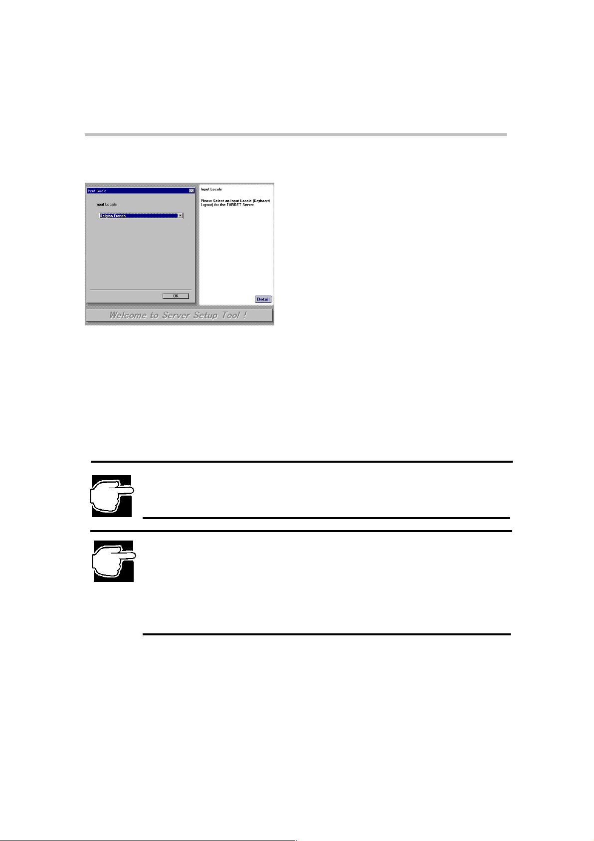
8. After the Start-up screen of the 'Server Setup TooL', the Input Locale screen is
displayed.
Input Locale screen
Select one of the following keyboard layouts.
Belgian French
German
Spanish
Swiss French
Swiss German
United Kingdom
U.S.
NOTE: The Input Locale screen only appears when you start the SST from the Startup Disk for the
first time. Locale information you select will be recorded on the Startup Disk. Once recorded, the
Input Locale screen will not be displayed again when you start the SST from the Startup Disk.
NOTE: To reconfigure the locale setting, you must record the locale setting on the Startup Disk using
the following procedure (1) or (2), then reinstall Windows 2000 Server / Windows NT Server 4.0
using the SST automatic installation procedure.
(1) Create a Startup Disk from [Utilities-Create Floppy Disks] and start the SST on the server from
the Startup Disk and select locale setting.
(2) Start the SST on another system and select locale setting. Select [Utilities-Setup Information]
and click [Save] on the' Confirm Parameter Settings' screen. The locale setting will be recorded
on the Startup Disk.Next start the SST on the server from the Startup Disk.
Page 10

Server Set up TooL
Starting SST on another system
4
Starting SST on another system
The Server Setup TooL can be started on a system installed with either one of the
following operating systems:
Windows 2000, Windows NT, Windows 98, Windows 95
To start the 'Server Setup TooL' from another system(s):
1. Insert the SST CD-ROM into the CD-ROM drive of the chosen operating system.
2. After the 'Input Locale' screen is displayed, select one of the keyboard layouts.
3. After finishing the Locale setting, the SST Main menu is displayed.
NOTE: The Input Locale screen is always displayed when you start the SST on another system.
Locale information you select will be recorded only when you select [Utilities-Setup Information] and
click [Save] on the' Confirm Parameter Settings' screen.
NOTE: When the 'Server Setup TooL' has been started on another system, you can use only the
utility option in the 'Main menu'.
If the Auto-Run function is not available, the' Server Setup TooL' can not be started on another
system.
Page 11
Server Set up TooL
Main Menu
5
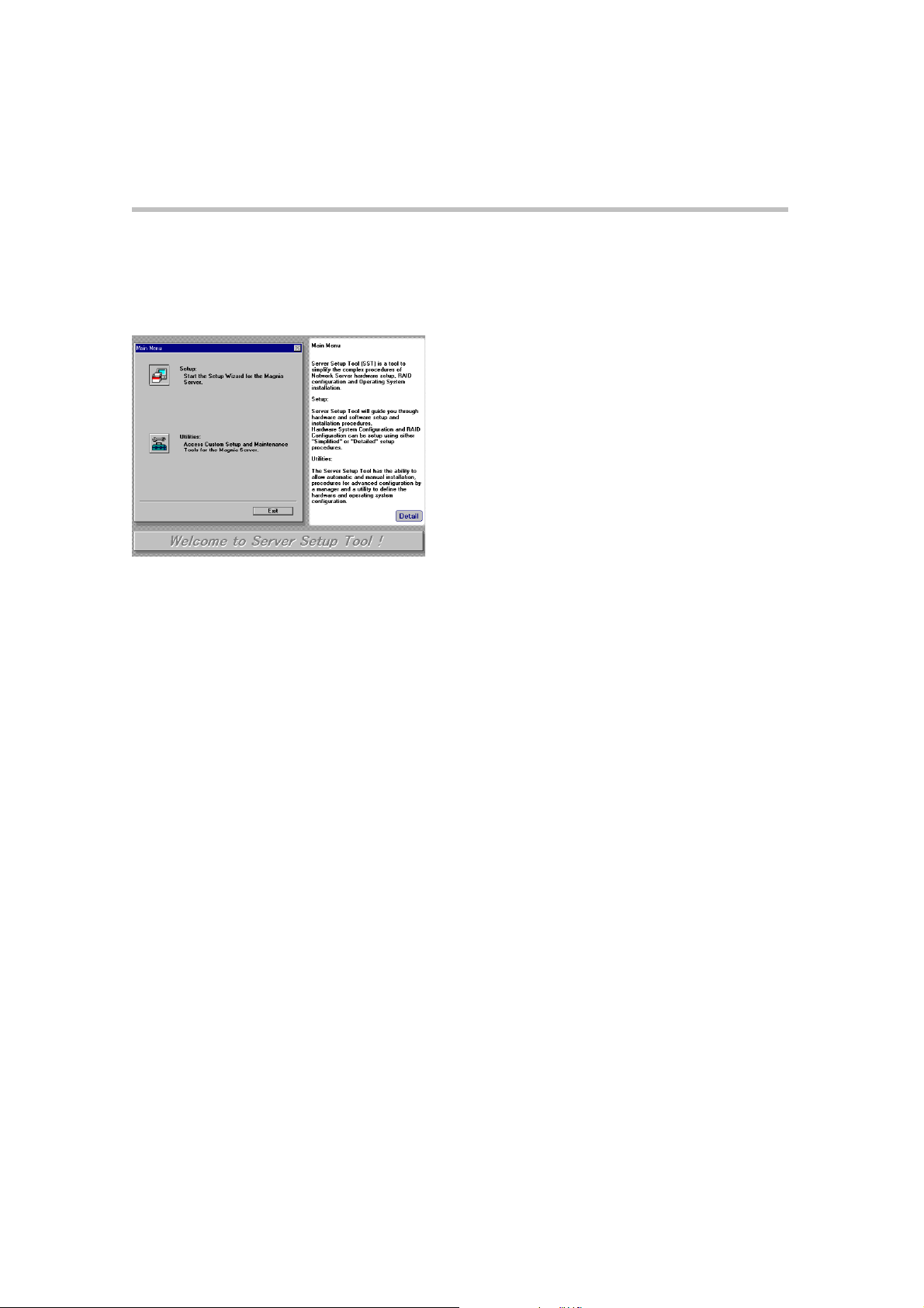
Main Menu
Mai n Men u scr een
Setup
The setup option is an automated installation process of the hardware and operating
system. The process guides you through a series of questions and then automatically
configures the system and installs the software. For more information, refer to Chapter 2.
[Setup].
Utilities
The utilities option contains additional programs to customize the installation and manage
the hardware and network configuration. For more information, refer to Chapter 3.
[Utilities].
Page 12

Page 13

Chapter 2
Page 14
Setup Wizard
Hardware System Configuration
Set up
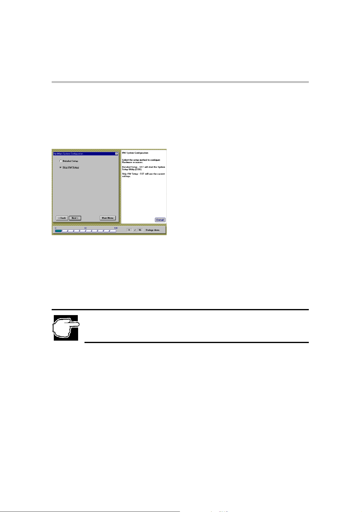
Hardware System Configuration Setting
6
After selecting
displayed.
Detailed Setup
The System Setup Utility enables the system hardware to be configured.
(For more information, refer to "System Configuration Setup in
the MAGNIA7100 User's Guide".)
Skip HW Setup
Choose this option to skip the hardware configuration setup process. Any existing configuration
remains unchanged
Setup
.
from the SST Main menu, the Hardware System Configuration screen is
Hardware System Configuration screen
NOTE: Select [Detailed Setup] if you are setting up the computer for the first time.
Page 15
Set up
e
7
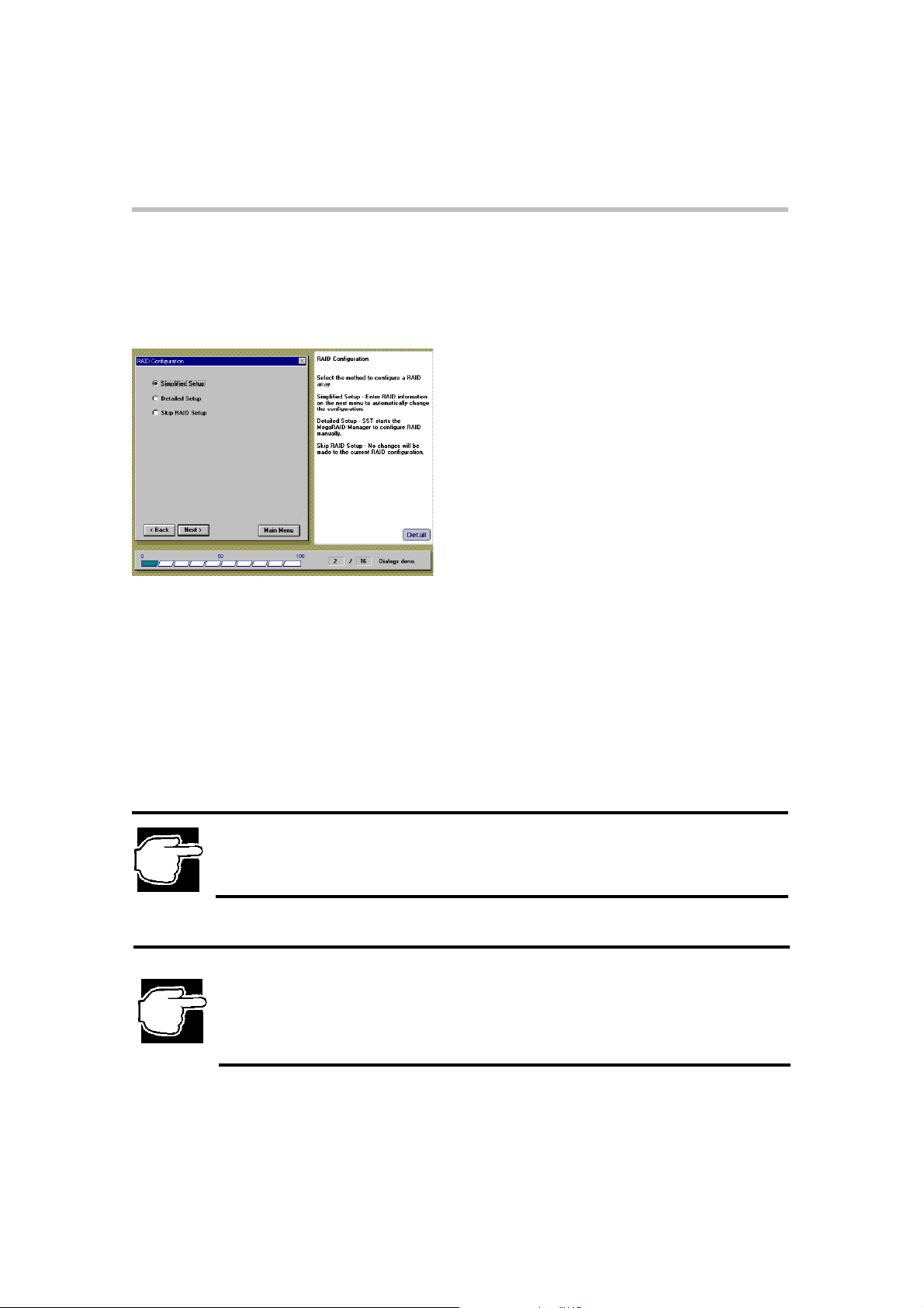
RAID Configuration Setting
RAID Configuration Setting
After selecting a 'Hardware System Configuration' option, the RAID configuration screen is
displayed (only if the RAID Controller exists).
RAID Configuration screen
Simplified Setup
This option allows you to input RAID type, Hot Spare option, and other RAID
configuration information during the setup process.
Detailed Setup
This option manually starts the RAID configuration utility, allowing the array to be
manually configured.
(For more information, refer to the MegaRAID User's Manual.)
Skip RAID Setup
Skip set-up of the RAID device.
NOTE: If you are setting up the computer for the first time and a RAID array has not been configured, us
[Simplified Setup] or [Detailed Setup].
NOTE: If you want to use another configuration which cannot be configured using [Simplified Setup]:
(For example: multiple array group, multiple MegaRAID adapters, RAID10, RAID50, etc.), select
[Detailed Setup].
For Details about [Simplified Setup], click [Detail] and refer to 'Server Setup TooL' Help.
Page 16

Set up
Simplified RAID Configuration Setting
Simplified RAID Configuration Setting
After selecting an option in the 'Simplified RAID Configuration' display the 'Simplified
RAID
Configuration Setup' screen is displayed.
Simplified RAID Configuration Setup screen
8
RAID0 (The required number of HDDs is one or more.)
Multiple HDDs are grouped and constructed as a unique logical device.
Since the data is recorded in the grouped HDDs in a dispersed manner, the writing and
reading performance of the HDDs is improved.
RAID1 (The required number of HDDs is two.)
RAID1 consists of two HDDs, the same data is always written to the HDDs. Therefore, if
one HDD is damaged, the operation can be continued by the other HDD.
RAID5 (The required number of HDDs is three or more.)
Multiple HDDs are grouped and constructed as a unique logical device. Since the data and
the parity are recorded in the grouped HDDs in a dispersed manner, if one HDD is
damaged, the operation can be continued by the other HDD.
Hot Spare (applicable if RAID1 or RAID5 is selected.)
Hot Spare is a spare HDD in stand-by conditionand automatically substituted for a
damaged HDD.
HDD Assignment - Use this many ?
Select from the list, the number of HDDs for the RAID configuration. When "MAX" has
been selected, RAID is structured with the maximum number of HDDs (= 8) available in
each RAID configuration.
Page 17
Set up
9
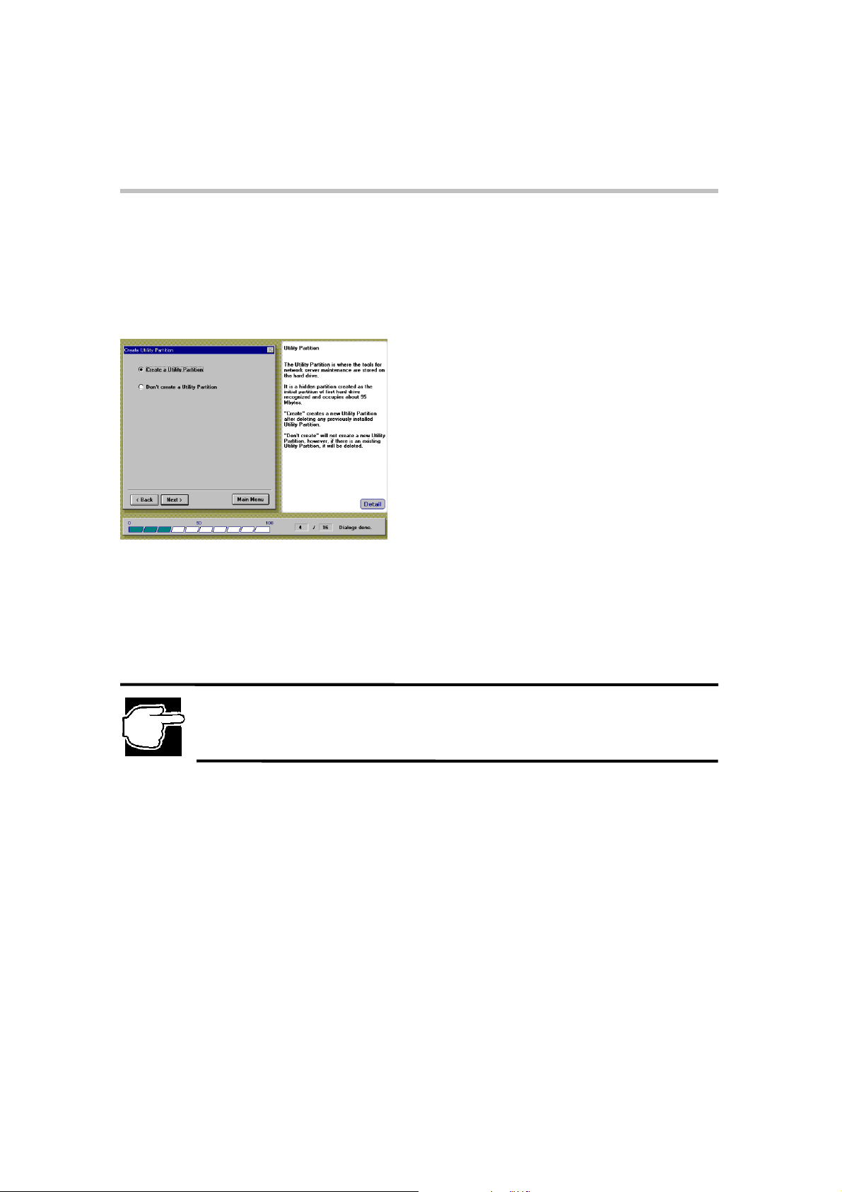
Create Utility Partition
The Utility Partition contains software tools used for maintaining your computer. The Utility
Partition is a hidden partition which resides on the computer's primary hard disk drive and can
be accessed during the boot process. The partition requires about 90 MB of freely available disk
space.
Create Utility Partition
Create Utility Partition screen
Create a Utility Partition
A 'Utility Partition' is created. When the Utility Partition is created, each utility
program is installed. For more information, refer to Chapter 3. [Utilities].
Don't create a Utility Partition
A 'Utility Partition' is not created.
NOTE: Ifa previous' Utility Partition' exists, it will be deleted and new partition created.
Page 18
Set up
Operating System Installation Selection
10
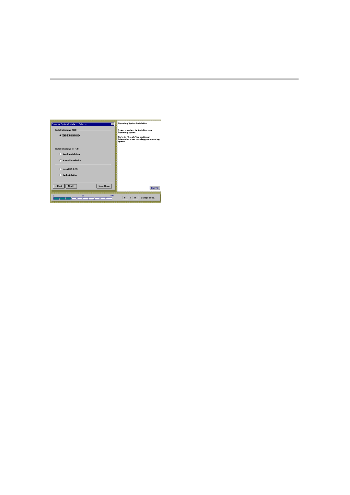
Operating System Installation Selection
After selecting a 'Utility Partition' option, the Operating System Installation Selection
menu is displayed.
Operating System Installation screen
Install Windows 2000
Quick Installation
Guides you through a quick installation of Windows 2000 Server using the 'Server
Setup
TooL's' automatic installation procedure.
Install Windows NT 4.0
Quick Installation
Guides you through a quick installation of Windows NT 4.0 Server using the 'Server
Setup TooL's' automatic installation procedure.
Manual Installation
Allows a manual installation of the Windows NT 4.0 Server. The required
Diskettes for manual installation will be automatically created.
Install MS-DOS
Allows you to install MS-DOS.
No Installation
Skips the installation of the operating system
Page 19

11
Set up
Operating System Installation Selection
NOTE: If you want to install Windows NT Server 4.0 without using the SST, create the required
Installation diskettes in the Utility menu (Refer toChapter 2 – Windows NT Manual Installation without
using SST and the MAGNIA7100 User's Guide for more Information).
If you select [Install MS-DOS], the 'Server Setup TooL creates a disk partition (from 50MB to
2,048MB).
Page 20
Set up
Locale Settings (Windows 2000 Quick Installation)
12
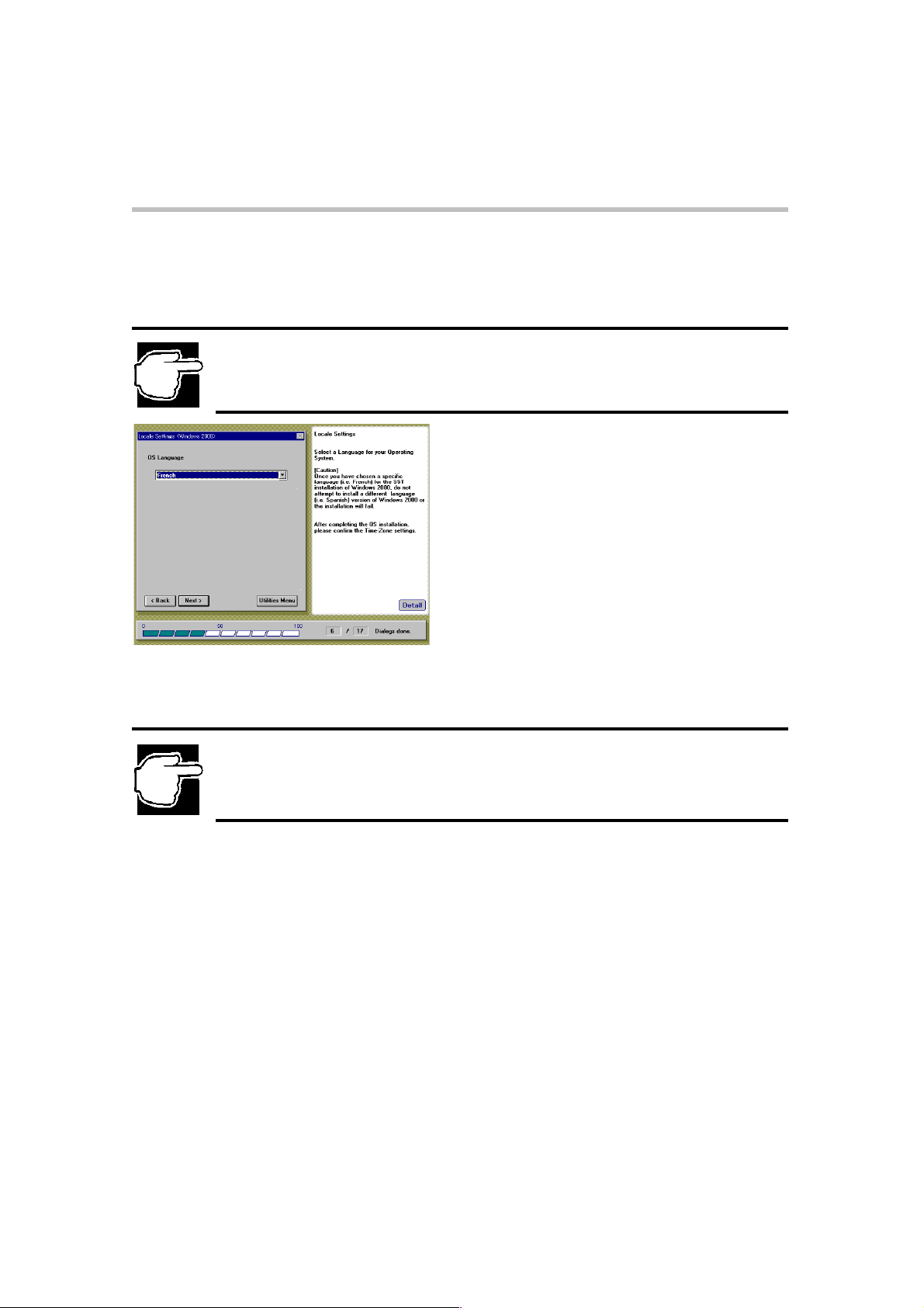
Windows 2000 Quick Installation
Locale Settings
NOTE: When you select the "Install Windows 2000 – Quick installation" option, the following Locale
Settings screen is displayed.
Locale Settings screen
Select a Language for your Operating System (OS).
NOTE: You must select the same OS languages as provided on your OS CD-ROM. Once you have
chosen a specific language [i.e. French] for the SST installation of Windows 2000, DO NOT attempt
to install a different language version [i.e. Spanish] of Windows 2000 or the installation will fail.
Page 21
Set up
Create Disk Partition (Windows 2000 Quick Installation)
13
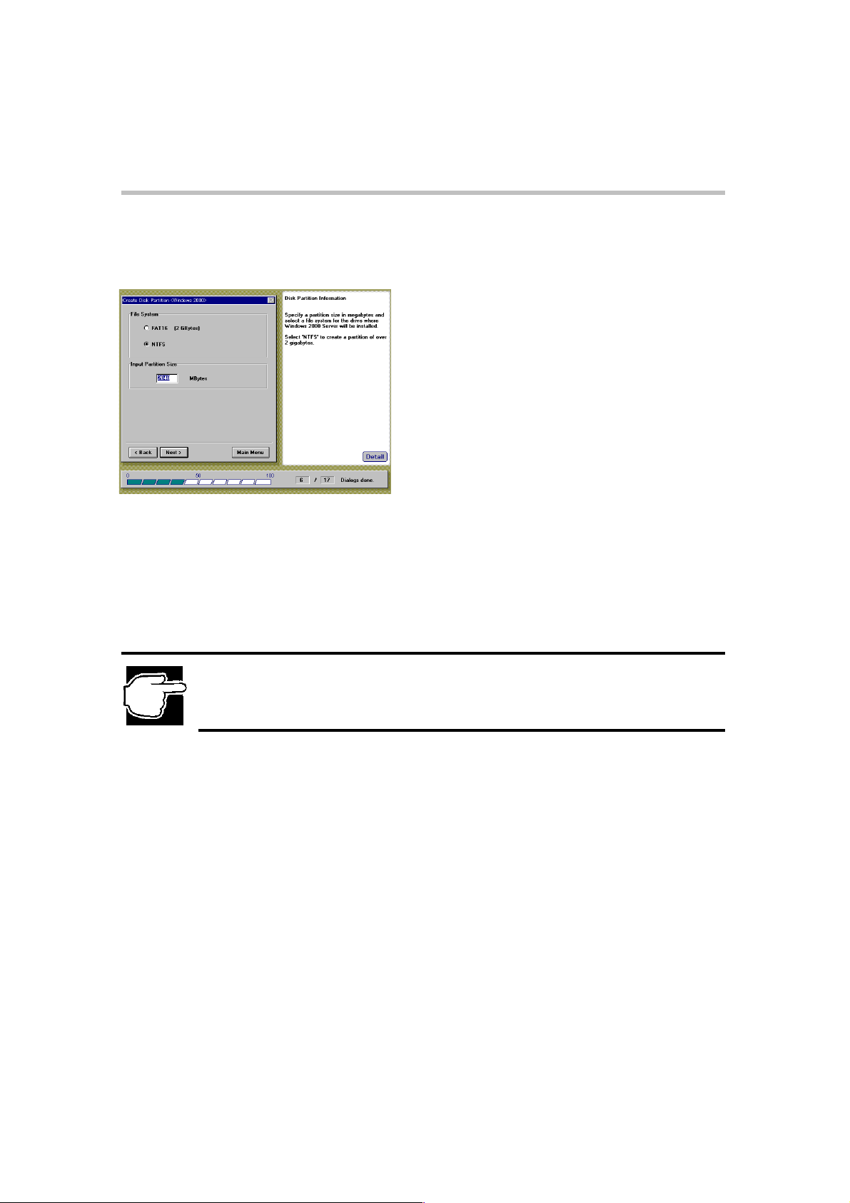
Create Disk Partition
After specifying the OS language, the 'Create Disk Partition' screen is displayed.
Create Disk Partition screen
Selectafilesystem.
FAT16
Createsa file system using the FAT16 format (File Allocation Table with 16-bit entries).
NTFS
Creates a file system using the NTFS format (NT File System).
NOTE: If you select "FAT16", the SST will create a partition the size of 2048MB.
If you select "NTFS" and enter a partition size larger than one available on the partition,the SST will
create the default partition (2048MB).
Input Partition Size
Enter the size of the disk partition you want to create, then press [Enter].
Page 22
Set up
User Information Settings (Windows 2000 Quick Installation)
14
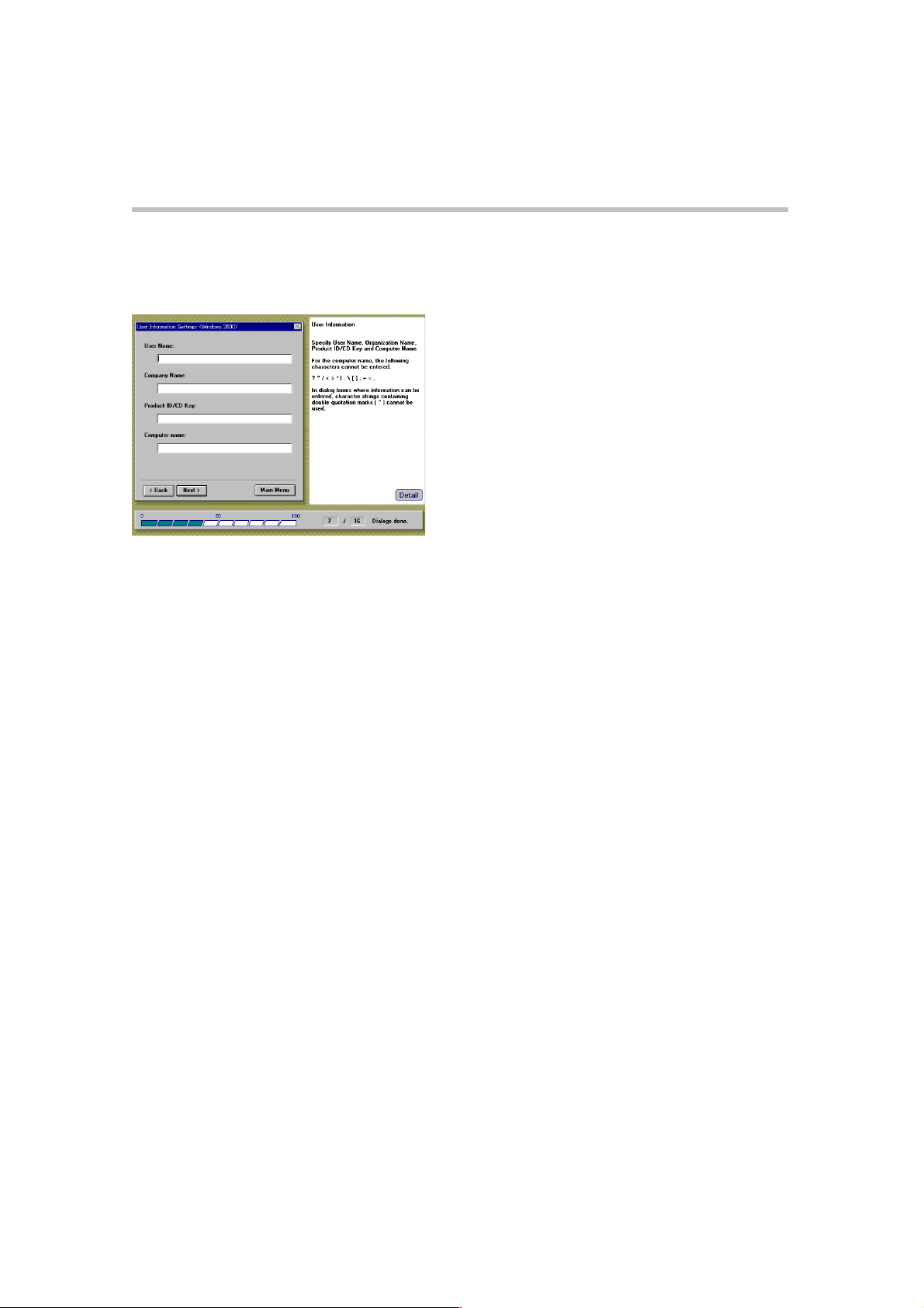
User Information Settings
After specifying the disk partition parameters, the 'User Information Settings' menu is displayed.
User Information Settings screen
Enter the following user settings:
User Name
Name of the user (administrator).
Company Name
Enter the name of the Company or organization (optional).
Product ID/CD Key
Product ID or CD-key of the Windows 2000 Server CD-ROM.
Computer Name
Identifies the computer to the rest of the network. The identifying name should be 15
alphanumeric characters or less.
Page 23
Set up
15
License Mode Setting (Windows 2000 Quick Installation)
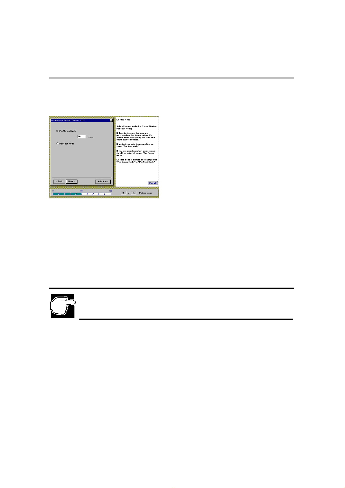
License Mode Setting
After you have specified user information, the 'License Mode Setting' screen is displayed.
License Mode Setting screen
The operating system license can be structured in one of two ways:
Per Server Mode
The server's license specifies the number of clients.
The number of users for a server should not be less than the number of client computers that
can simultaneously connect to that server.
Per Seat Mode
Each client computer (seat) has its own license, allowing it to access any Windows 2000 Server
on the network.
NOTE: If you are not sure which license mode to use, select "Per Server Mode". The license mode
can be changed only once from "Per Server Mode" to "Per Seat Mode",according to the license
Contract.
Page 24
Set up
Server Role Setting (Windows 2000 Quick Installation)
16
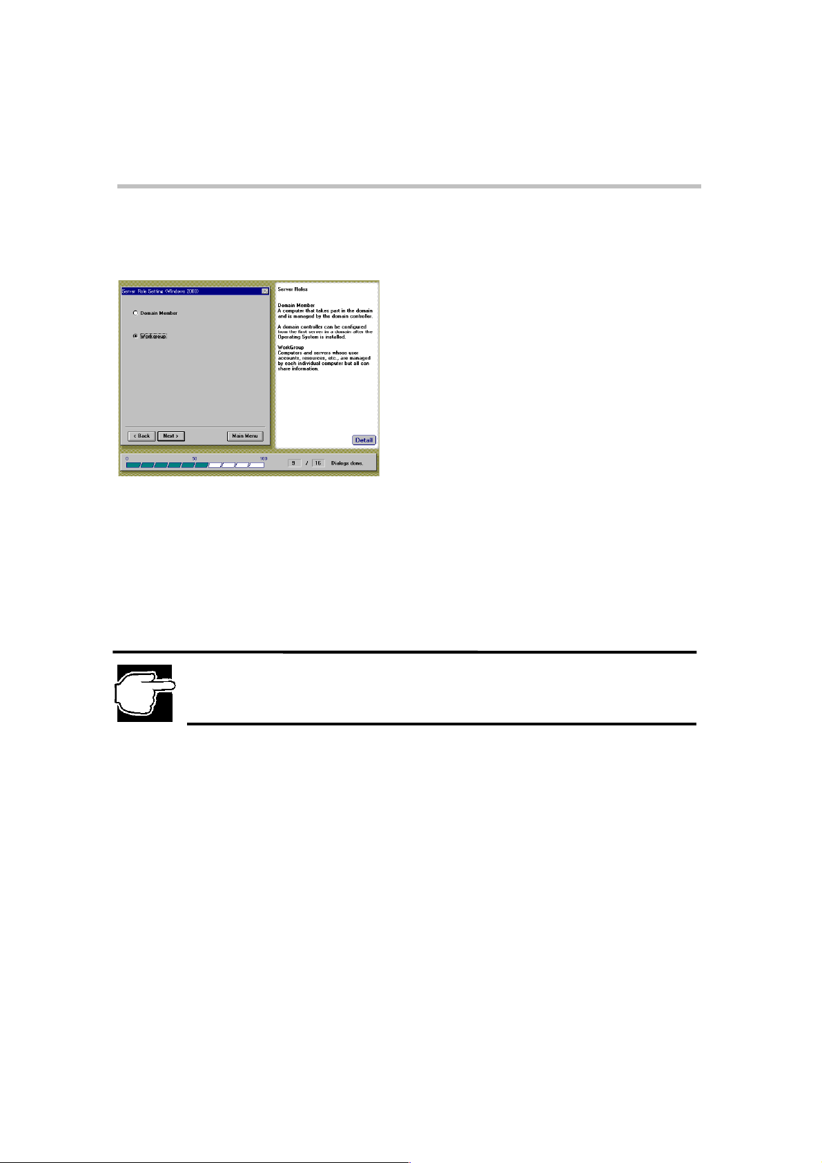
Server Role Setting
After specifying the 'License Mode Setting', the 'Server Role Setting' screen is displayed.
Server Role setting screen
Select one of the following server role setting options, then click [Next].
Domain Member
Configures the computer as part of the domain, controlled by a domain controller.
Workgroup
User accounts and resources are controlled by the individual computers.
NOTE: To make your server a domain controller, you must install 'Active Directory' afterinstalling the
Windows 2000 Server. SeeChapter 2. section [After Installation (Windows 2000)] .
Page 25
Set up
Network Setting [1] (Windows 2000 Quick Installation)
17
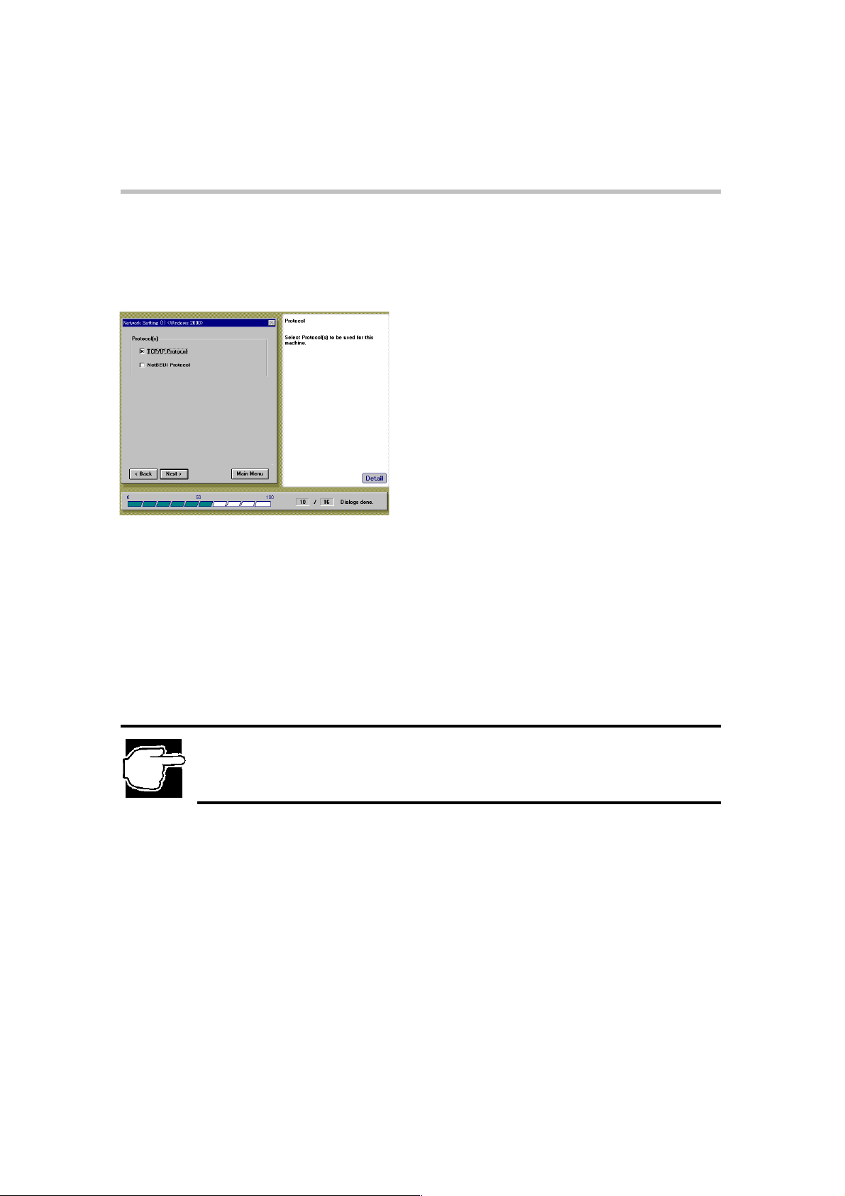
Network Setting [1]
After specifying the 'Server Role Setting', the 'Network Setting' [1] screen is displayed.
Use this screen to specify the network communication protocol.
Network Setting [1] screen
Select the communication protocol required , then click [Next].
TCP/IP Protocol
Send communication protocol
Internet protocol
NetBEUI Protocol
NetBIOS expansion user interface
NOTE: If “TCP/IP Protocol has been selected”, the SNMP service will be installed automatically.
Page 26
Set up
Network Setting [2] (Windows 2000 Quick Installation)
18
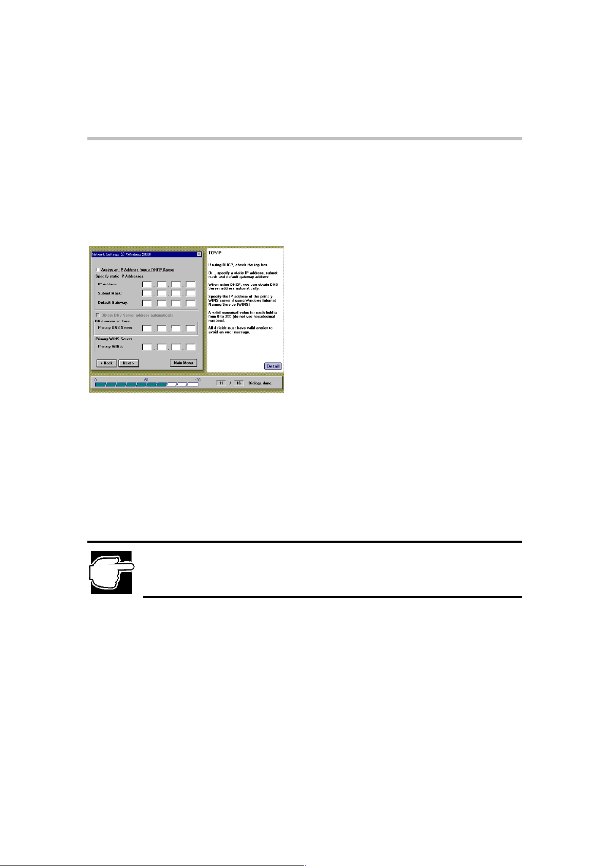
Network Setting [2]
If TCP/IP is specified as the network communication protocol, the Network Setting [2] screen is
displayed. The Network Setting [2] screen allows you to specify the IP Address, Subnet Mask,
Default Gateway Address, Primary DNS Server Address, and Primary WINS Server Address
for your computer.
Network Setting [2] screen
To set up the network communication protocol, complete one of the following steps to
specify the IP Address for your computer:
1. To have the domain server automatically assign the IP addresses, Subnet Masks and
Default Gateway to your computer, select "Assign IP Address from DHCP Server".
2 If you are using the Windows Internet Name Service (WINS), in the Primary WINS
Server pane, enter the IP address for your Primary WINS Server.
NOTE:Decimal numbers (from 0 to 25) must be used for; IP Address, Subnet Mask, Default
Gateway Address, Primary DNS Server and Primary WINS Address.
Page 27
Set up
Network Setting [3] (Windows 2000 Quick Installation)
19
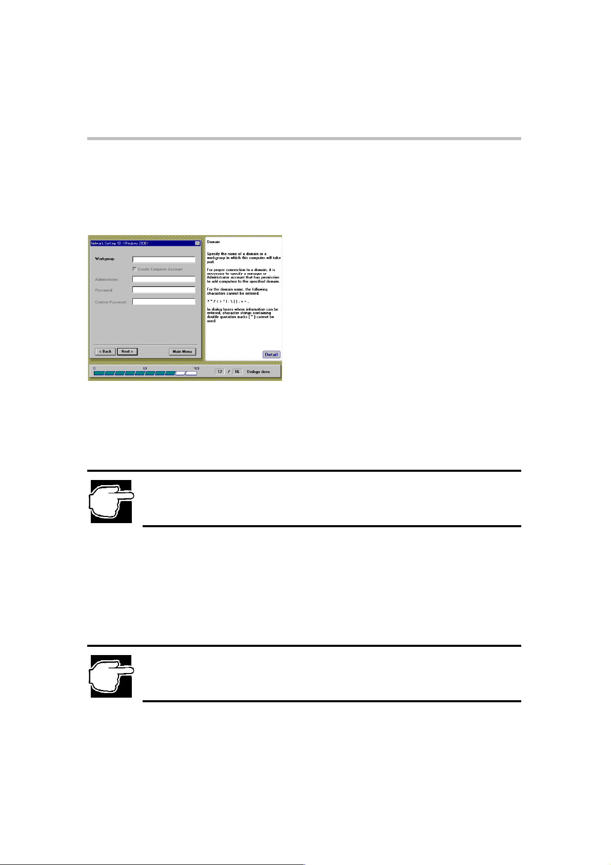
Network Setting [3]
After you have specified the IP addresses for your computer, the Network Setting [3] screen is
displayed. Use this screen to specify the name of the domain or workgroup in which your
computer takes part.
Network Setting [3] screen
To specify the domain or workgroup to which your computer belongs to:
1. Enter the name of a domain or a workgroup. To register the server in the domain for the
first time, select [Create Computer Account].
2. If the server has already been registered for the domain, or you want assign this server in the
workgroup, click [NEXT].
NOTE: If the server has already been registered fora domain, or you want to incorporate the server
as part of a workgroup, it is not necessary to create a computer account.
3. In the Administrator text box, enter the name of the manager or administrator account that
has permission to add computers to the specified domain.
4. In the Password text box, enter the password of the domain manager account.
5. In the Confirm Password text box, reenter the password to confirm it.
NOTE: Do not use double-quote marks (“) for all items.
Page 28

Set up
Update Driver Settings (Windows 2000 Quick Installation)
20
Update Driver Settings
After the 'Network Settings' screen, the 'Update Driver Settings' screen is displayed (only if the
MR493 RAID Controller exists).
Update Driver Settings screen
RAID Controller Driver
Driver for MR493 RAID controller
NOTE: The drivers for the server hardware are found on the CD-ROM of the' Server Setup TooL..
You may, however, have installed equipment that was shipped on diskettes with newer driver release
versions. If you need to use the drivers on diskettes continue with this section. If you wish to use the
drivers from the CD-ROM, proceed to the next step by clicking [NEXT].
Page 29

Set up
21
Services and Application Installation (Windows 2000 Quick Installation)
Services and Application Installation
Clicking
Installation' screen.
ASD Driver
The ASD automatically 'shuts-down' the system. The server can also be powered-down by
pressing the DC power switch.
AMI RAID Utility (MR493 RAID Controller only)
The AMI RAID Controller utility:
(If the MR493 RAID controller is not installed on your computer, these items will be grey-ed
out)
Next
on the 'Update Driver Settings' screen displays the 'Services and Application
Services and Application Installation screen
Power Console
Monitors the RAID configuration.
Service
Extracts log information.
SNMP Agent
Used by TCP/IP-based management applications.
Select the following options:
To install each application automatically, check the [Install] box.
To install each application driver from the diskette, check the [From FD/CD] box.
Page 30

Set up
on(
Services and Application Installation (Windows 2000 Quick Installation)
NOTE: Ifa later version of the application is also available on diskette, check [From FD / CD] option..
If TCP/IP protocol is not installed (then the SNMP service is also not installed), the SNMP agent of
the AMI RAID utility can also not be installed.
NOTE:Applicable to AMI MR438 RAID Controller: If you want to install the AMI RAID Utility, the
utilitymust be installed manually after the Windows 2000 Server installation. See [Chapter 2 – After
Installati
Windows 2000)]andtheMegaRAID User's Manual.
22
Page 31

Set up
23
Setup Option (Windows 2000 Quick Installation)
Setup Option
After you have specified the installation options for 'Services and Application', the Setup Option
screen is displayed. Use this screen to specify the setup installation features you wantenabled,
during the installation process.
Setup Option screen
Beep sound in case of disk change
Emits an audible alert (beep) to change storage media (i.e CD-ROM and diskette).
Start installation according to parameter settings during boot time
The next time the SST starts, installation automatically begins after a confirmation
message, using the configuration information currently stored on the Startup Disk. If this
option is not selected, the SST starts normally at the Main Menu.
Confirm partition information during installation procedure
A dialog box is displayed, requiring you to confirm the deletion of the existing partition.
If a disk partition already exists, a confirmation message is displayed, asking if you want
to delete the partition. If this option is not checked, setup deletes the partition without
prompting you for confirmation.
NOTE: If you have an existing partition (such as Windows 2000 or Windows NT) , the partition is first
deleted before installation.
Page 32

Set up
Confirm Parameter Settings (Windows 2000 Quick Installation)
Confirm Parameter Settings
After you have specified the setup installation features, the 'Confirm Parameter Settings' screen
is displayed. This screen displays a window listing the configuration and setup parameters that
you have chosen.
Confirm Parameter Settings screen
24
Review the information displayed on the 'Confirm Parameter Settings' screen to ensure its
accuracy. To change a setting, highlight the item you wish to change and click on
The setup wizard will return to that screen and allow you to make changes.
If you are satisfied with the installation settings, click
Execute
.
Jump
.
Page 33

Set up
Locale Settings (Windows NT 4.0 Quick Installation)
25
Windows NT 4.0
Quick Installation
Locale Settings
NOTE: When the “Install Windows NT – Quick installation” option is selected, the following' Locale'
Settings screen is displayed.
Locale Settings screen
Select the Language for your Operating System.
NOTE: You must select the same OS languages as provided on your OS CD-ROM. Once you have
chosen a specific language [i.e. French] for the SST installation of Windows NT, do not attempt to
install a different language version [i.e. Spanish] of Windows NT, or the installation will fail.
Page 34

Create Disk Partition
NOTE: When the “Install Windows NT 4.0 – Quick installation” is selected, the following 'Create Disk
Partition' menu is displayed.
Set up
Create Disk Partition (Windows NT 4.0 Quick Installation)
Create Disk Partition screen
26
Select one of the following options:
FAT16
Creates a file system using the FAT16 format (File Allocation Table with 16-bit entries).
FAT16 format limits the size of any given disk drive (i.edrive D) to 2GB.
NTFS
Creates a file system using the NTFS format (NT File System). NTFS limits the size of the
disk drive to 2GB.
NTFS Expansion
Creates a file system using the NTFS format, with an expansion capability to increase the size
of the partition. This capability increases the limit on the disk device to 8GB.
In the 'Input Partition Size' text box, enter the size of the disk partition you want to create.
NOTE: If “NTFS Expansion” is selected, the partition size enteredwill be ignored. If t “NTFS
Expansion” is not selected, a partition size of 512MB to 2048MB can be entered .
NTFS Expansion uses the entire remaining disk space to create the partition.
Page 35

Set up
27
User Information Settings
After specifying the disk partition parameters, the 'User Information Settings' menu is displayed.
Enter the following user settings:
User Name
Name of the user (administrator).
User Information Settings (Windows NT 4.0 Quick Installation)
User Information Settings screen
Company Name
Name of the Company or organization (optional).
Product ID/CD Key
Product ID or CD-key of the Windows NT Server 4.0 CD-ROM.
Computer Name
Identifies the computer to the rest of the network. The identifying name should be 15
alphanumeric characters or less.
Page 36

License Mode Setting (Windows NT 4.0 Quick Installation)
License Mode Setting
After specifying user information, the 'License Mode Setting' screen appears.
License Mode Setting screen
The operating system license can be structured in one of two ways:
Set up
28
Per Server Mode
The server's license specifies the number of clients.
The number of users for a server should not be less than the number of client computers that can
simultaneously connect to that server.
Select one of two license modes and click [Next].
Per Seat Mode
Each client computer (seat) has its own license, allowing it to access any Windows NT server
on the network.
NOTE: If you are unsure of which license mode to use, select “Per Server Mode”. The license mode
can be changed only once from “Per Server Mode” to “Per Seat Mode”, according to the license
contract.
Page 37

Set up
29
Server Role Setting (Windows NT 4.0 Quick Installation)
Server Role Setting
After specifying the 'License Mode Setting', the 'Server Role Setting' screen is displayed .
Server Role Setting screen
The 'Server Role Setting' screen allows you to specify the role your computer plays within the
network (domain).
Select the server's role from one of the following options, then click [Next].
Primary Domain Controller
Configures the computer to manage the domain.
Backup Domain Controller
Configures the computer to synchronize with the primary domain controller as a backup server.
As a backup server, the computer stores a copy of the security database on its hard disk drive.
When necessary the backup server can also assume the role of the primary domain controller.
Domain Member
Configures the computer as part of the domain, controlled by a domain controller.
Workgroup
User accounts and resources are controlled by the individual computers.
Page 38

Set up
Network Setting [1] (Windows NT 4.0 Quick Installation)
30
Network Setting [1]
After you have specified the server role, the 'Network Setting' [1] screen is displayed. This
screen is where you specify the network setup method.
Network Setting [1] screen
Select one of the following network settings, then click [Next].
Simplified Setting
Allows you to manually set up a protocol,domain or workgroup. The LAN driver is
automatically installed including existing service settings.
Detailed Setting
SST will stop the auto install at the point where the Windows NT Server 4.0 setup program
accepts the user input. After the user's input ends, the process continues.
NOTE: If “Detailed Setting” is selected, proceed to [Chapter 2 - Update Driver Settings (Windows NT
4.0 Quick Installation)].
Page 39

Set up
31
Network Setting [2] (Windows NT 4.0 Quick Installation)
Network Setting [2]
After specifying the network adapter driver, the Network Setting [2] screen is displayed.
Use this screen to specify the network communication protocol.
Network Setting [2] screen
Select the communication protocol being used.
TCP/IP Protocol
Send communication protocol
Internet protocol
NetBEUI Protocol
NetBIOS expansion user interface
NOTE: If “Simplified Setting” and select “TCP/IP Protocol”is selected, the SNMP service will be
installed automatically
Page 40

Set up
Network Setting [3] (Windows NT 4.0 Quick Installation)
32
Network Setting [3]
If TCP/IP is specified as the network communication protocol, the Network Setting [3] screen is
displayed. The Network Setting [3] screen allows you to specify the IP Address, Subnet Mask,
and Default Gateway Address and Primary WINS Address for your computer.
Network Setting [3] screen
To set up the network communication protocol:
1. Complete one of the following steps to specify the IP Address for your computer:
z To have the domain server automatically assign the IP addresses,
Subnet Masks and Default Gateway to your computer, select "Assign
IP Address from DHCP Server".
z To specify the server's IP Address, Subnet Mask, and Default
Gateway Address, DO NOT select "Assign IP Address from the
DHCP Server". Enter the addresses as described above.
2. If you are using the Windows Internet Name Service (WINS), in the Primary WINS
Server pane, enter the IP address for your Primary WINS Server.
NOTE:Decimal numbers (from 0 to 255) must be used for: IP Address, Subnet Mask, Default
Gateway Address and Primary WINS Address
Page 41

Set up
33
Network Setting [4] (Windows NT 4.0 Quick Installation)
Network Setting [4]
After specifying the IP addresses for your computer, the Network Setting [4] screen is
displayed. Use this screen to specify the name of the domain or workgroup in which your
computer takes part.
Network Setting [4] screen
To specify the domain or workgroup your computer belongs to:
1. In the domain Name text box, enter the name of the domain or workgroup for your
network. To register this server in the domain for the first time, select [Create
Computer Account].
2. If the server has already been registered for the domain, or you want to assign this
server to be included as partofthe workgroup, click [Next].
NOTE: If the server has already been registered in a domain, or you want to incorporate the server
aspart a workgroup, it is not necessary to create a computer account.
3. In the Administrator text box, enter the name of the manager or administrator account that
has permission to add computers to the specified domain.
4. In the Password text box, enter the password of the domain manager account.
5. In the Confirm Password text box, re-enter the password to confirm it.
NOTE: Do not use double-quote marks (“) for all items.
Page 42

Set up
Update Driver Settings (Windows NT 4.0 Quick Installation)
Update Driver Settings
After the 'Network Settings' screen, the 'Update Driver Settings' screen is displayed.
Update Driver Settings screen
NOTE: The drivers for the server hardware are found on the Server Setup TooL CD-ROM. You may,
however, have installed equipment that was shipped on diskettes that include drivers with a newer
release version.. If you need to use the drivers on diskettes, continue with this section. If you wish to
use the drivers from the CD-ROM, proceed to the next step by clicking [NEXT].
34
SCSI Driver (AIC-788x)
On-board SCSI driver for MAGNIA7100
SCSI Driver (AIC-7899)
On-board SCSI driver for MAGNIA7100
RAID Controller Driver
Driver for RAID controller
LAN Driver
Driver for Network adapter
Page 43

Set up
35
Services and Application Installation (Windows NT 4.0 Quick Installation)
Services and Application Installation
Clicking [
Installation' screen.
ASD Driver
The ASD automatically shuts down the system. The server can now be powered off by pressing
the DC power switch.
AMI RAID Utility
The AMI RAID Controller utility:
Power Console
Monitors the RAID configuration.
Next]
on the 'Update Driver Settings' screen displays the 'Services and Application
Services and Application Installation screen
Service
Extracts log information.
SNMP Agent
Used by TCP/IP-based management applications.
Select the following options:
To install each application automatically, check the [Install] box.
To install each application driver from the diskette, check the [From FD/CD] box.
NOTE: If you have the latest driver version on diskette, also check [From FD/CD]. If you do not
select “TCP/IP protocol” (then the SNMP service will also not be installed), the SNMP agent of the
AMI RAID utility cannot be installed.
Page 44

Set up
Setup Option (Windows NT 4.0 Quick Installation)
36
Setup Option
After you have specified the installation options for 'Services and Application', the Setup
Option screen appears. Use this screen to specify the setup installation features you want
enabled during the installation process.
Setup Option screen
Select any of the following features that you want to activate:
Beep sound in case of disk change
Emits an audible alert (beep) to change storage media (CD-ROM and diskette).
Start installation according to parameter settings at boot time
The next time the SST starts, installation begins automatically after a confirmation message,
using the configuration information currently stored on the Startup Disk. If this option is not
selected, the SST starts normally at the Main Menu.
Confirm partition information during the installation procedure
A dialog box is displayed requiring you to confirm the deletion of the existing partition.
If a disk partition already exists, a confirmation message is displayed asking if you want to
delete the partition. If this option is not checked, setup deletes the partition without prompting
you for confirmation.
NOTE: If you have an existing partition (such as Windows2000 or Windows NT), the partition is
firstdeleted before installation.
Page 45

Set up
37
Confirm Parameter Settings (Windows NT 4.0 Quick Installation)
Confirm Parameter Settings
After setup of the installation features, the 'Confirm Parameter Settings' screen is displayed.
This screen displays a window listing the configuration and setup parameters that you have
chosen.
Confirm Parameter Settings screen
To start the installation process:
1. Review the information displayed on the 'Confirm Parameter Settings' screen to ensure that
the settings are correct.
To change a setting, highlight the item you wish to change and click
will return to that screen and allow you to edit changes.
2. If you are satisfied with the installation settings, click
Execute
Jump
. The setup wizard
.
Page 46

Set up
Windows NT 4.0 Manual Installation using SST
38
Windows NT 4.0
Manual Installation
using SST
When [Install Windows NT 4.0 - Manual Installation] is selected in the [OS Install
Selection] menu in the Toshiba Server Setup TooL, the hardware and the RAID system are
automatically configured, and the diskettes for manual installation are created
automatically. Once configured, boot the server with the setup disk supplied with the
Windows NT Server 4.0, and then install the Windows NT Server 4.0 manually.
The diskettes SST automatically creates the following drivers:
- Adaptec 788x Windows NT Driver
- Adaptec 7899 Windows NT Driver
- Intel LAN Windows NT Driver
Windows 2000
Manual Installation
without using SST
To install the Windows 2000 Server without using the Toshiba 'Server Setup TooL's',
automatic installation procedure, the MR493 RAID Controller driver diskette must be
used.
For more information, refer to the MAGNIA7100 User's Guide.
Page 47

Set up
39
Windows NT 4.0 Manual Installation without using SST
Windows NT 4.0
Manual Installation
without using SST
To install the Windows NT Server 4.0 without using the Toshiba 'Server Setup TooL's
automatic installation procedure, diskettes for manual installation must be made from the
"Create Floppy Disks" menu. After making the diskettes, follow the installation
instructions given in the MAGNIA 7100 User's Guide.
Create Floppy Disks for Manual Installation
1. Insert the SST Startup Disk.
2. Switch ON the server.
3. When the following message appears:
"Please insert the Server Setup TooL CD, then press any key."
Insert the SST CD-ROM and press any key.
4. The 'Server Setup TooL' starts.
5. Select the [Utilities] option in the "Main Menu".
Utility Menu screen
6. Select the following items, then select [OK].
- Adaptec 788x Windows NT Driver
- Adaptec 7899 Windows NT Driver
- Intel LAN Windows NT Driver
Page 48

Set up
Create Floppy Disks (Windows NT 4.0 Manual Installation without using SST)
Create Floppy Disks screen
7. Insert an unused diskette, then select [OK].
(If necessary, remove the Startup Disk.)
8. After creating the diskettes, you must label them. To check the label descriptions, select
[Detail] Æ [Create Floppy Disks] and srefer to SST Help.
- (FD label: Adaptec 788x FMS Windows NT 4.0)
- (FD label: Adaptec 7899 FMS Windows NT 4.0)
- (FD label: Intel EtherExpress PRO/100+ LAN Adapter Configuration and
Drivers Diskette Windows NT)
40
Page 49

Set up
41
After Installation (Windows 2000)
After Installation
(Windows 2000)
If Windows 2000 Server installation is complete,proceed as follows.
Setting up the Time Zone
1. Start the Windows 2000 Server and log on as the Administrator (or as a user having
equivalent access).
2. Run Date/Time Properties by clicking
double clicking
3. Click the
4. Check that the current Time Zone setting is correct. If incorrect, select the correct
setting and press [Ok].
Setting up the AMI RAID utility (MR438 RAID Controller only)
If the MR438 RAID Controller is installed on your server, and it uses the AMI RAID
utility (Power Console, Service, SNMP Agent), these utilities must be installed
manually after the Windows 2000 Server installation.
To install the AMI RAID utility, follow the instructions given in the MegaRAID User's
Manual.
Date/Time
Time Zone
.
tab.
Start,Settings,Control panel
,and
Setting up the Active Directory (Making this server a domain controller only)
If the TCP/IP protocol is installed and you want to make this server a domain controller
in your network, you must install 'Active Directory'. For more information about
installing the Active Directory, refer to the Windows 2000 Server Help.
Page 50

Set up
After Installation (Windows NT 4.0)
42
After Installation
(Windows NT 4.0)
If Windows NT Server 4.0 installation is complete, follow the procedure given below.
1. Start Windows NT Server 4.0 and logon as the Administrator (or as a user having
equivalent access).
2. Run Date/Time Properties by clicking
Date/Time
3. Click
4. Check that the current Time Zone setting is correct. If incorrect, select the correct setting
and press [Ok].
.
Time Zone
tab.
Selecting the display driver
To display in SVGA mode or above , the video driver from the retail driver included in
the Windows NT CD-ROM to the video driver included in the SST CD-ROM must be
changed. Before changing the display driver, the Windows NT Service Pack (version
higher than Service pack 4) must be installed. To install the Windows NT Service
Pack, follow you’re the installation instructions given in the MAGNIA 7100 User's
Guide..
On completion of the Windows NT Service Pack installation, follow the steps below.
Start,Settings,Control panel
, and double clicking
1. Start Windows NT Server 4.0, and log in using the Administrator ID or a User ID
having equivalent rights.
2. Run Display Properties from Windows NT, by clicking
panel
, and double-clicking
3. Select the
4. Insert the Toshiba 'Server Setup TooL' CD-ROM, and select
following path:
Select "ATI Rage IIC".
5. When the following message appears, select
You are about to install a third-party driver.
This driver was written by the hardware vendor, and is only provided here as a convenience.
For any problem with this driver, please contact the hardware vendor.
6. After copying files, restart the Windows NT Server 4.0 before making any changes
to the setting.
7. After log-in to the system, the 'Display Properties Dialog' is opened. Set the desired
display mode in the dialog, and then pressOK.
Settings
<CD-ROM>\PUBLIC\VIDEO\ATI\RAGE2C\NT
tab, click
Display
.
Display Type
, and then click
Yes
.
Start,Settings,Control
Change
.
Have disk
. Enter the
Page 51

Chapter 3
Page 52

Page 53

Utilities
43
How to Start Utilities
How to Start Utilities
About Utilities
The Utility Menu allows your system hardware settings to be modified and maintained . The
'Utility Menu' screen provides, the following utilities:
Setup Support
- Setup Information
- Create Floppy Disks
Hardware Setup
- HW System Configuration
- RAID Configuration
Maintenance
- HW Diagnostics
- Update Program
NOTE: Three methods are available to start the Utilities.Some utility programs however cannot be
executed according to the methods described, such . Items are greyed-out and cannot be executed.
Starting the Utilities program from SST CD-ROM with Startup Disk
1. Insert the SST Startup Disk.
2. Switch on the server.
3. When the following message is displayed:
"Please insert the Server Setup TooL CD, and press any key."
Insert the SST CD-ROM and press any key.
4. Once the 'Server Setup TooL' starts, the Main Menu is displayed. Select the
[Utility] option.
Selectable items when the Utilities is started from SST CD-ROM with Startup Disk
Selectable items
Setup Information
Create Floppy Disks
HW System Configuration
RAID Configuration
HW Diagnostics
Utility Menu screen (started from Startup Disk)
Page 54

Utilities
Starting the Utilities from the Utility Partition
Starting the Utilities from the Utility Partition
The Utility Partition is a partition where the maintenance tools are stored and created.
1. Switch on the server.
2. As the system boots, the following message (SMC BIOS) is displayed, press <Ctrl> +
<t> within four seconds after the message appears to boot to the Utility Partition.
SMC BIOS xxx.xx.xxx
©xxxx,TOSHIBA CORPORATION. All Rights Reserved.
44
Press <Ctrl>+<t> keys
after the appearance of the message.
Key is accepted. (*)
3. When the Utility Partition is activated, the following message is displayed:
Utility Partition is successfully activated.
NOTE: If the disk access fails, the following message appears:
Error detected. Utility Partition is not activated.
If the Utility Partition does not exist, the following message appears:
Utility Partition is not found.
4. When selecting the Utilities" option in the [Main Menu] screen, the utility menu is
displayed.
Selectable items when the Utilities is started from Utility Partition
within four seconds
Selectable items
Setup Information
Create Floppy Disks
HW System Configuration
RAID Configuration
HW Diagnostics
Update Program
Partition)
Utility Menu screen (started from Utility
Page 55

Utilities
Starting the Utilities on another system
45
Starting the Utilities on another system
1. Insert the SST CD-ROM in to the machine running Windows 2000, Windows NT,
Windows 98 or Windows 95.
2. In a short time, the 'Input Locale' screen is displayed. On this screen select a keyboard
layout.
3. On completion of the locale setting, the SST Main menu is displayed.
Selectable items when the Utilities is started from another system
Selectable items
Setup Information
Create Floppy Disks
Utility Menu screen (started from another system)
NOTE: The Input Locale screen will always be displayed when the SST is started on another
system. Locale information you select will be recorded only when you select [Utilities-Setup
Information] and click [Save] on the 'Confirm Parameter Settings' screen.
NOTE: When the 'Server Setup TooL' is started on another system, only the utility of the Main menu
can be selected. If the Auto-Run function is not available, the 'Server Setup TooL' will not start on
that system.
Page 56

Utilities
Setup Support
46
Utility Menu
Setup Support
Setup Information
Clicking 'Setup Information' starts the Setup Information wizard and opens the 'Setup Wizard'
dialog box. In this box choices can be made on how the SST configures the server, hardware,
RAID, Utility Partition, and another system during the installation procedure. This menu reads
the current setting information from the SST Startup Disk and arranges the settings.
NOTE: To save the setup information created on the Startup Diskette, click [Save] on the Confirm
Settings page.
NOTE: The Input Locale screen appears only when you start SST from Startup Disk for the first time.
Locale information you select will be recorded on the Startup Disk. Once recorded, the Input Locale
screen never appears when you start SST from the Startup Disk.
NOTE: The Input Locale screen will alwaysbe displayed when the SST is started on another system.
Locale information you select will be recorded only when you select [Utilities-Setup Information] and
click [Save] on the Confirm Parameter Settings screen.
NOTE: To reconfigure the locale setting, you must record the locale setting on a Startup Diskusing
the following procedure (1) or (2), then reinstall Windows 2000 Server / Windows NT Server 4.0
using SST automatic installation procedure.
(1) Create Startup Disk from [Utilities-Create Floppy Disks] and start SST on the server from the
Startup Disk and select locale setting.
(2) Start SST on another system, select locale setting and select [Utilities-Setup Information] and
click [Save] on the Confirm Parameter Settings screen. The locale setting will be recorded on
the Startup Disk. Next start SST on the server from the Startup Disk.
Page 57

Utilities
47
Create Floppy Disks
Create Floppy Disks
Clicking
can create from the Utilities menu.
The following check boxes are available in the Create Floppy Disks screen.
Checking the appropriate box, lists the available diskette titles found in the menu.
Create Floppy Disks,
NOTE: If you start the Utility menu from another system, you must create the diskettes after
selecting [Control Panel] – [Console] – [Screen Option] then set to [Full Screen].
lists the system boot, diagnostic, and installation diskettes you
Create Floppy Disks screen
Windows 2000
Lists the diskette titles that are necessary for installing the Windows 2000 Server.
Windows NT
Lists the diskette titles that are necessary for installing the Windows NT Server 4.0.
OTHER
Lists all diskette titles except those for the Windows 2000 Server and Windows NT
Server 4.0.
Page 58

Utilities
Create Floppy Disks
48
Available Diskettes
The following diskettes can be created from the "Create Floppy Disks" menu.
Startup Disk
This diskette is necessary to start the SST.
DOS Disk
This diskette starts the utility programs used on the server.
HW Diagnostics Program
This diskette is used to boot from the floppy disk drive and run this program.
The HW Diagnostics Program checks the operation of the hardware and the input/output device
as well as displaying the configuration information of the system.
Adaptec 788x Windows NT Driver
This diskette is used on Windows NT for the MAGNIA7100 on-board SCSI controller.
Adaptec 7899 Windows NT Driver
This diskette is also used on Windows NT for the MAGNIA7100 on-board SCSI controller.
Intel LAN Windows NT Driver
This diskette is used on the Windows NT for the LAN controller installed on the network
server.
Sensor Data and LCD Setup Tool
This diskette is used to install this program on the client computers.
The 'Sensor Data and LCD Setup Tool' can update the sensor information on the SMC and
system boards.
Create Floppy disks
1. Select the title of the diskette you want to create, and click [OK] to continue.
2.
Insert a blank diskette when instructed.
Page 59

Utilities
49
HW Setup
HW Setup
HW System Configuration
The 'System Setup Utility' (SSU) begins by selecting [HW System Configuration]. The
SSU manages/configuresthe hardware resources of the system (i.e memory addresses,
I/O ports, DMA channels, interrupt levels, etc.).
For more information, refer to the MAGNIA7100 User's Guide.
RAID Configuration
The MegaRAID Manager begins by selecting [RAID Configuration].
Creating, repairing and deleting the RAID configuration as well as creatingthe hotspare are available to the MegaRAID Manager.
For more information, refer to MegaRAID User's Manual.
Maintenance
HW Diagnostics
The HW Diagnostics is a program that monitors the operation and configuration of the
server while in use..
For more information, refer to [Chapter 4 HW Diagnostics].
Update Program
To update the software installed in your server 'Utility Partition', click
Program
. The 'Update Program' screen displays the following three options:
Update all programs
Updates all programs in the Utility Partition.
Update individual programs
Select the programs you want to update.
Update System Setup Utility
Updates the 'System Setup Utility' in the 'Utility Partition'.
Update
Page 60

Page 61

Chapter 4
Page 62

HW Diagnostics
About HW Diagnostics
50
About HW Diagnostics
HW Diagnostics performs a diagnostics test of the server's hardware devices. You can
select a single device or a combination of devices to test.
Use the HW Diagnostics Program to check:
- That the server operates normally.
- For abnormal operation or any failure while the server is in use.
- Thatthe optional devices are working normally.
Not all failures may be detected by the HW Diagnostics Program. In this case use the System
Setup Utilities (SSU) to check the error log compiled by the system board.
Starting HW Diagnostics Program
Starting from the SST CD-ROM with Startup Disk
1. Insert the Startup Disk.
2.Switch on the server.
3. When the following message is displayed:
"Please insert the Server Setup TooL CD, then press any key,"
insert the SST CD-ROM and press any key.
4. Select [Utility] option from the SST Main Menu.
5. Select [HW Diagnostics] option.
The system reboots, and the 'HW Diagnostics Program' starts automatically.
After the test, when the HW Diagnostics Program is complete , the Menu of the 'Server Setup TooL'
is displayed after the system has rebooted.
NOTE: To finish the HW Diagnostics Program by the Utility Partition, select [Main Menu] – [Exit] of
the Server Setup TooL.
Starting up by the floppy disk
1. Insert the floppy disk of HW Diagnostics Program.(Set the floppy disk writable.)
2. Switch on power to the server.
Once the system reboots, the HW Diagnostics Program starts.
Page 63

HW Diagnostics
51
Starting from the Utility Partition
NOTE: To start the HW Diagnostics Program from the diskette, create the HW Diagnostics Program
diskette from the “Create Floppy Disks” menu in the SST.
Starting from the Utility Partition
1. Switch on the server.
When the system reboots, the following message appears; press <Ctrl> + <t>.
SMC BIOS xxx.xx.xxx
©xxxx,TOSHIBA CORPORATION. All Rights Reserved.
Input <Ctrl>+<t> keys
within four seconds after
the appearance of the message.
Key is accepted. (*)
2. When the Utility Partition is activated, the following message appears:
Utility Partition is successfully activated.
NOTE: If disk access fails, the following message appears:
Error detected. Utility Partition is not activated.
If the Utility Partition does not exist, the following message appears:
Utility Partition is not found.
3. Select "Utility" option from the SST [Main Menu] screen.
4. Select [HW Diagnostics] option.
After the completion of the test, close the 'HW Diagnostics Program'. The Toshiba 'Server
Setup TooL' menu appears again after rebooting.
NOTE: To finish the HW Diagnostics Program started from the Utility Partition, select [Main Menu] –
[Exit] of the Server Setup TooL.
Page 64

HW Diagnostics
Items of HW Diagnostics
52
Items of HW Diagnostics
When any key is pressed on the initial screen of the Toshiba HW Diagnostics Program, the
main HW Diagnostics Program menu appears:
Main menu of HW Diagnostics Program
[01.DIAGNOSTIC TEST]
Test hardware.
For more information, refer to [Chapter 4 Diagnostics Test – (01. DIAGNOSTIC
TEST)].
[02.RUNNING TEST]
Automatically execute the Diagnostics tests in a user-defined sequence.
For more information, refer to [Chapter 4 Diagnostics Test – Running Test (02.
RUNNING TEST TEST)].
[03. Log Utilities]
Displays the error information.
For more information, refer to [Chapter 4 Diagnostics Test – (03.Log Utilities)].
[04.SYSTEM CONFIGURATION]
Displays the system configuration.
For more information, refer to [Chapter 4 Diagnostics Test – (04.System Configuration
Display)].
[99.EXIT]
Terminates the HW Diagnostics Program, the server then reboots and the SST Menu is
displayed.
Page 65

HW Diagnostics
53
Diagnostics Test
Diagnostics Test (01. DIAGNOSTIC TEST)
1. From the 'Diagnostics Test Menu' (DIAGNOSTIC TEST MENU) screen, select the desired
subtest number from the subtest menu. (To return to the 'Main Menu', select "99" or
"Esc".)
01 MEMORY TEST
02 KEYBOARD TEST
03 DISPLAY TEST
04 FLOPPY DISK TEST
05 PRINTER TEST
06 SCSI HDD TEST
07 NPX TEST
08 CACHE MEMORY TEST
09 SCSI TEST
10 CD-ROM TEST
11 SAF-TE TEST
12 SMC TEST
99 EXIT to DIAGNOSTICS MENU
2. After selecting the desired subtest, the following message appears.
(For more detailed information on each item, refer to [Chapter 4 Diagnostics Test – Details
of test items and Error log information]):
Diagnostics TEST - TEST PARAMETER
[01.Go to Test]
Start the test. To stop the test program, press <Ctrl> + <Break>.
[02.Test Loop]
Selecting "YES" restarts the test cycle and increments the pass counter each time the
test cycle ends.
Selecting "NO" returns the subtest menu to the main menu after the test is completed.
[03.Error Stop]
Selecting "YES" stops the test program when an error is detected.
Selecting "NO" keeps the test running even if an error is detected.
Page 66

HW Diagnostics
Running Test
Running Test (02.RUNNING TEST)
The following test parameter is displayed when "02 RUNNING TEST" is selected.
(ToreturntotheMainMenu,select"99"or"Esc".)
Running TEST - TEST PARAMETER
[01.Go to Test]
To start the running test. To stop the test program, press <Ctrl> + <Break>.
[02.Test ITEM EDIT]
To choose the test items under the RUNNING Test.
[03.Finish BUZZER Sound]
When the Server finishes the running test, a beep sound is emitted.
[99.Exit to DIAGNOSTICS MENU]
To return to the HW Diagnostics Main Menu.
In the initial setting, the following items are automatically executed:
54
01.MEMORY TEST 01.Conventional memory
03.DISPLAY TEST 01.VRAM W/R/C
03.DISPLAY TEST 02.640*480 Mode display
03.DISPLAY TEST 03.1024*768 Mode display
06.SCSI HDD TEST 02.Connection
07.NPX TEST 01.NPX test
08.CACHE TEST 01.Constant date test
08.CACHE TEST 02.Address pattern test
08.CACHE TEST 03.Increment / Decrement test
08.CACHE TEST 04.Caching data test
10.CD-ROM TEST 02.Random address read
11.SAF-TE TEST 01.SAF-TE TEST
12.SMC TEST 01.Self&Sensor TEST
04.FLOPPY DISK TEST 01.Sequential address read
When the test is complete, the test result appear on the screen in larger text.
Page 67

HW Diagnostics
55
No error has been detected. OK
The test has been compulsorily ended or any error has been detected. FAILED
Running Test
NOTE: To check the error log, select [03.LOG UTILITIES] in the main menu. For the key operation
on the error log display, refer to “Checking error log” in this chapter. If the test in progress has been
terminated, the test result will not be displayed.
Page 68

HW Diagnostics
Selecting items of Running test
56
Selecting Items of Running Test
A screen is displayed when [02. TEST ITEM EDIT] is selected. This menu shows the current
items in the running test, and will allow you to add or delete individual tests.
TEST ITEM EDIT FOR RUNNING TEST
Adding Test Items
To add a test item to the Running test, press the <Ins> key, select a test item using the arrow
keys, and press <Enter> to select subtests.
To return to the previous menu, press the <Esc> key.
NOTE: Do not add the subtest [01. Press Key Display] of [02. KEYBOARD TEST] to the Running
test. This subtest requires a key input so that the Running test in progress is terminated if this
subtest is added to the Running test.
Do not select the subtest only [08. CACHE MEMORY TEST] as the Running test.
Deleting Test Items
Move the cursor on to a test item , press <Del> to delete the selected test item.
Saving Test Items
When leaving the test items selection menu, the message "Do you save data?" is displayed.
Select "YES" to save setting, or "NO" to revert to the previously saved settings.
Page 69

57
HW Diagnostics
Selecting items of Running test
NOTE: The edited test items are saved in system memory. When you restart the HW Diagnostics
Program, the test items are returned to the initial setting.
Page 70

HW Diagnostics
Execution of test
58
Execution of Test
During 'DIAGNOSTIC TEST' and 'RUNNING TEST', the following screen is displayed:
Sample screen during the test
XXXX TEST
Indicates the name of the test being executed.
SUB TEST
Indicates the subtest number, and the step number of the test being executed.
PASS COUNT
Indicates the pass count of the test.
WRITE DATA
Indicates the write-data.
READ DATA
Indicates the read-data.
ADDRESS
Indicates the address of the test being executed.
STATUS
Indicates the status of the test being executed.
If any errors occur during the test, the message "ERROR OCCURRED!" is displayed. The
error name is also displayed under the message "ADDRESS".
Page 71

HW Diagnostics
59
Details of Test Items and Error Log Information
Details of Test Items and Error Log Information
The following are Test items and Error log information:
[01. MEMORY TEST]
To run the memory.
[01. Conventional memory]
This test writes data to conventional memory (0 to 640 KB), and then reads the new data and
compares the result with the test data.
[02. Expansion memory]
This test writes constant data to all of the memory area, and then reads the data and
compares it with the test data.
[03. RAM refresh]
This test writes test data to the memory, and then reads the data after one refresh cycle and
compares the data with the test data.
[04. Stress test]
This test writes data to the protected mode memory (from 1 MB to maximum), and then
reads the data and compresses it with the write data.
NOTE: The [02. Expansion memory], [03. RAM refresh] and [04. Stress test] tests all memory area.If
the capacity of mounted internal memory is large, the tests may take a few hours.
MEMORY TEST (RAM) Error log
Status Error name Meaning
01 PARITY ERROR Parity error
02 PROTECTED MODE NOT CHANGE ERROR The Shift to the protected mode
failed.
FF DATA COMPARE ERROR Data comparing error
[02. KEYBOARD TEST]
The 'Keyboard Test' contains three subtests that test the computer's keyboard and mouse
actions.
[01. Pressed key display]
When you execute this subtest, the keyboard layout is drawn on the display. When any key
is pressed, the corresponding key appears on the display. Pressing and holding a key enables
the auto-repeat function, causing the key's displayed character to blink.
Before executing the test, select 'Keyboard Type' in the test parameters.
Page 72

HW Diagnostics
KEYBOARD TEST
[02. Keyboard LED on]
The system flashes the Num Lock, CapsLock, and Scroll Lock LEDs.
[03. PS/2 mouse]
This subtest checks whether a PS/2 mouse is connected..
During the test, no message appears on the screen.
KEYBOARD TEST (KBD) Error log
Status Error name Meaning
01 CLOCK LINE ERROR L Clock line error (LOW)
02 CLOCK LINE ERROR H Clock line error (HIGH)
03 DATA LINE ERROR L Data line error (LOW)
04 DATA LINE ERROR H Data line error (HIGH)
07 INTERFACE ERROR Interface error
08 RESENDING ERROR Sending/receiving error
09 ID ERROR ID error
FF DATA COMPARE ERROR Data comparing error
[03. DISPLAY TEST]
To test the function of the display.
60
[01. VRAM W/R/C]
This subtest writes constant data to video RAM. This data is then read from the video RAM,
and compared with the original data.
[02. 640*480 Mode display]
This subtest displays data in 256 color display mode in 640 * 480 resolution.
[03. 1024*768 Mode display]
The test data is displayed in 256 color display mode in 1,024 * 768 resolution.
DISPLAY TEST (CRT) Error Log
Status Error name Meaning
FF DATA COMPARE ERROR Data comparing error
[04.FLOPPY DISK TEST]
To test the floppy disk drive, prepare a formatted floppy disk.
Before starting the test, select the following parameters.
Test Drive number
Designates the floppy disk drive to drive A or B.
This server does not support drive B. Select drive A.
Media type
Designates the format type (1.44 MB or 720 KB) of the diskette for the test.
This system does not support type 1.2 MB format.
Page 73

HW Diagnostics
61
Test start track number
Designates the first track number for the test.
At the start of the test, the message to change the HW Diagnostics test diskette with the test
diskette is displayed. Change the disk..
[01. Sequential address read]
This subtest continuously reads data from all tracks on a diskette.
[02. Random address/data W/R/C]
This subtest writes random data to random addresses on all tracks on the diskette. The data is
then read and compared to the original data.
FLOPPY DISK TEST (FDD) Error log
Status Error name Meaning
01 BAD COMMAND ERROR Bad command error has occurred
02 ADDRESS MARK NOT FOUND The address mark has not been found
03 WRITE PROTECED Floppy disk is write-protected
04 RECORD NOT FOUND The record has not been found
06 MEDIA CHANGE LINE ERROR The media change line is bad
08 DMA OVERRUN ERROR DMA OVERRUN occurred
09 DMA BOUNDARY ERROR DMA BOUDARY occurred
10 CRC ERROR CRC check error
20 FDC ERROR FDC error
40 SEEK ERROR Floppy disk seek error
FLOPPY DISK TEST
NOTE:For this test, the test diskette must be formatted and write-enabled.
Check that there is no important data on the test diskette after Running [02.Random address/data
W/R/C].
NOTE:If the HW Diagnostics Program has been run from the diskette, replace the diskette after testing.
Page 74

HW Diagnostics
PRINTER TEST
[05. PRINTER TEST]
To test the operation of the printer port.
[01. Print Ripple pattern]
This subtest prints characters for codes 20h through 7Eh, line-by-line, while shifting one
character to the left at the beginning of each new line.
Print Ripple Pattern Example
PRINTER TEST (PRT) Error log
Status Error name Meaning
01 TIME OUT Time out of printer
control
62
[06. SCSI HDD TEST]
This test checks the HDD functions connected to the SCSI-Bus through ASPI driver software.
Before running the test, the items for testing must be designated.
HOST ID NUMBER
This option sets the target host adapter number. When you choose "ALL", the subtest, tests all
disks connected to the server The next options, SCSI ID and CHANNEL number, will be
ignored.
SCSI ID NUMBER
This option sets the SCSI ID to test. You can specify just one ID to test,except ID:7.
CHANNEL NUMBER
If the server has multiple SCSI channels, this option sets the channel number to test.
[01. Sequential address read]
This subtest is a sequential reading of all the blocks on the HDD starting at block 0.
[02. Connection]
This subtest reads the logical sector at the end of the HDD, and then recognizes if the drive
is connected.
Page 75

HW Diagnostics
63
SCSI HDD TEST (HDD)
Status Error name Meaning
01 CHECK CONDITION OR BAD COMAND Bad command error
03 DRIVE SELECTION FAILED ID selection error
04 TARGET DRIVE BUSY The target drive is busy
05 SCSI BUS TIME OUT Time out error of SCSI bus
09 DMA BOUNDARY ERROR DMA BOUNDARY occurred
0D COMMAND TERMINATED A command terminated
0E QUEUE FULL Command queue is full
80 NO SENSE The sense data is invalid
81 RECOVERD ERROR The execution of the command has
82 NOT READY The condition does not satisfy for
83 MEDIUM ERROR An error occurred because of the
84 HARDWARE ERROR A hard error that is impossible
85 ILLEGAL REQUEST CBD is illegal
86 UNIT ATTENTION The function of hard disk drive has
87 DATA PROTECT Data protection error
89 VENDOR UNIQUE A unique error of disk maker
8A COPY ABORTED Stop of COPY command
8B ABORTED COMMAND The execution of a command
8C EQUAL The comparing result of the
8E MIS COMPARE Comparing command error
E0 STATUS ERROR Status error
F0 OTHER ERROR Other errors
FE NO DRIVE ERROR The target drive has not been found
FF DATA COMPARE ERROR Data comparing error
SCSI HDD TEST
NOTE: The [01. Sequential address read] tests all areas of the hard disk drive. If the capacity of
installed hard disk drives are large enough, the test may take a few hours.
If you do not know where the hard disk drives are connected (host ID, SCSI ID and channel number
of the SCSI controller), you can find them from [01.INQUIRY] of [09.SCSI TEST].
correctly finished because of
recovery treatment.
the command execution
failure of a medium
to recover occurred during
command execution
been changed
is correctly stopped
search data command is
satisfied
Page 76

HW Diagnostics
NPX TEST
* Meaning of Details Information (DETAILS = XXXXXXXXXXXXXXXX)
AA BB CC DD EEEE FFFF
AA : Host and Channel number that the hard disk drive is connected to.
BB : Driver completion status
CC : ASPI status
DD : Host status
EEEE : Sense data
FFFF : Sense code
[07. NPX TEST]
This tests the computer's floating data processing unit functions.
[01. NPX test]
This test checks the Addition and Multiplication functions of the coprocessor.
NPX TEST (NPX) Error log
Status Error name Meaning
01 NO CO-PROCESSOR Co-processor recognition error
02 CONTROL WORD ERROR Set control word error
03 STATUS WORD ERROR Status word error
04 BUS ERROR BUS error
05 ADDITION ERROR Addition test error
06 MULTIPLICATION ERROR Multiplication test error
07 EXCEPTION ERROR Exception error
64
[08. CACHE MEMORY TEST]
To test the L2 caching unit.
CACHE MEMORY TEST (CAH) Error log
Status Error name Meaning
01 MEMORY PARITY ERROR Memory parity error
02 PROTECT MODE ERROR The shift to the protected mode failed.
03 CACHING ERROR An error occurred on the cache system.
FF DATA COMPARE ERROR Data comparing error
[09. SCSI TEST]
To test the SCSI devices.
Before running the test, the parameters must be set. If "HOST ID NUMBER" is set to "ALL",
the " SCSI ID NUMBER" and "CHANNEL NUMBER" are ignored.
[01. INQUIRY]
This subtest issues the INQUIRY command to the SCSI bus and displays the results of
the messages returned from the devices on the SCSI bus. After specifying the valid host
and channel number, the INQUIRY command is sent to the target SCSI bus. It then
displays the result code from ID0 through ID15.
Page 77

HW Diagnostics
65
CHAN
Indicates the ASPI angle ID and host adapter
HOST
The channel number in the target host adapter.
ID00, 01, 02 …
The SCSI ID number in the target host adapter.
The types of SCSI devices to be displayed are as follows:
HDD Hard disk device CD CD-ROM device
CMT Magnetic tape device SCN Scanner
PRT Printer MO Magnet-optic disk device
PRC Processor (SAF-TE) MC Media changer
WON Write Once device COM Communication device
??? Undefined device --- Not connected
The following screen gives an example when the built-in CD-ROM drive is connected
to the on-board SCSI controller, and when the built-in hard disk drives are connected to
the MegaRAID Adapter.
SCSI TEST
INQUIRY Screen
Page 78

HW Diagnostics
CD-ROM TEST
[10. CD-ROM TEST]
To test the computer's CD-ROM functions,
insert the SST CD-ROM for the test.
[01. Sequential address Read]
This subtest is a sequential reading of one block unit of all the logical addresses.
[02. Random Address Read]
This subtest reads data at random addresses.
For the error log information, refer to [Log Utilities] of SCSI HDD TEST.
[11. SAF-TE TEST]
To check the SAF-TE function and the status LED of the hard disk drives.
[01. SAF-TE test]
The SAF-TE test detects the SAF-TE controller and checks its operation by flashing the
LED for each hard disk drive.
The test first detects the SAF-TE controller and shows the connecting destination of the
detected SAF-TE controller (host number, SCSI ID, and channel number) with model name.
--HT—ID----CH--VENDOR—PRODUCT-------FAN—PS--SLOT
XX XX XX XXXXX XXXX XX XX XX
66
After detecting the SAF-TE controller, the following message is displayed:
SAF-TE LED Steady ON (Faulty Flag) Hit any key
When the message above is displayed, check that all LEDs of the hard disk drives are lit
(orange). Press the <Enter> key.
SAF-TE LED Blinking (Rebuilding Flag) Hit any key
When the message above is displayed, check that all LEDs of the hard disk drives are
flashing (orange). Press the <Enter> key.
SAF-TE LED Steady ON (Rebuild Interrupted) Hit any key
When the message above is displayed, check that all LEDs of the hard disk drives are lit
(orange). Press the <Enter> key.
SAF-TE LED Flashing (Rebuilding Flag) Hit any key
When the message above is displayed, check that all LEDs of the hard disk drives are
flashing (orange). Press the <Enter> key.
Page 79

HW Diagnostics
67
SAF-TE TEST (SAF) Error log
Status Error name Meaning
01 SAF-TE TEST ERROR SAF-TE controller has not been detected.
[12. SMC TEST]
To test the SMC functions and the LED display functions.
[01. Self&Sensor test]
The self and sensor test for each controller is performed with the results displayed.
[02. Front Panel test]
Verifies the functions of LED, LCD panel. Check that:
LED test:
LCD test:
SAF-TE TEST
SAF-TE LED Reset (No Error Flag) Hit any key
When the message above is displayed, check that all LEDs of the hard disk drives switch
off. Press the <Enter> key.
Please check LED all GREEN. OK (Y) / FAILED (N)
Please check LED all ORANGE. OK (Y) / FAILED (N)
Please check LED all OFF. OK (Y) / FAILED (N)
Please check HddFaultLED ON. OK (Y) / FAILED (N)
Please check LCD all ON. OK (Y) / FAILED (N)
Please check LCD all OFF. OK (Y) / FAILED (N)
Page 80

HW Diagnostics
Log Utilities
68
Log Utilities
The 'Log Utilities' function logs error information generated while a test is in progress.
TheresultsarestoredinRAM..
The error logs can be checked by selecting [03. LOG UTILITIES] in the main menu.
Selecting [01.LOG UTILITIES] displays the following message:
Log Utilities Screen
XXXXX ERRORS
The message shows the number of errors.
PASS COUNT
If the test parameter "Test Loop" is set to "Yes" in the test, the pass count is displayed.
CNT
CNT shows the number assigned, according to the order in which the errors occurred..
TEST
XXX XX
digits 1-3
MEMORY TEST RAM NPX TEST NPX
KEYBOARD TEST KBD CACHE MEMORY TEST CAH
DISPLAY TEST CRT SCSI TEST SCS
FLOPPY DISK TEST FDD CD-ROM TEST CDR
PRINTER TEST PRT SAF-TE TEST SAF
SCSI DISK TEST HDD SMC TEST SMC
digits 4-5
digits 6-7
XX
:Abbreviation of the test in which the error occurred.
: displays the subtest number in which the error occurred.
: displays the step number in which the error occurred. (Depending on the
test, Digits 6-7 are not always displayed.)
Page 81

HW Diagnostics
69
PASS
Displays the pass count where the error occurred.
STS
Displays the error status.
The meaning of the error status depends on the test item.
ADDR
Displays the address where the error occurred
WD
Displays the write-data when the error occurred.
RD
Displays the read-data when the error occurred.
ERROR NAME / DETAILS
Displays the error name and its detailed information.
Key operation for Log Utilities
Log Utilities
To scroll the error log screen, or to save and to clear the error log information, use the
following keys:
<↓> key : scrolls to the next page.
<↑> key : scrolls to the previous page.
<Esc> key : finishes the error log screen and returns to the main menu.
<1> key : clears the error log information.
<2> key : prints out the error log information.
<3> key : reads the error log information saved on the floppy disk.
<4> key : saves the error log information on the floppy disk.
NOTE: When the error log information is cleared with the key operation as describedabove, the error
information recorded on the diskette will also be cleared.
Page 82

HW Diagnostics
SCSI DEVICES
System Configuration Display
HW Diagnostics
System Configuration Display
Selecting [04.SYSTEM CONIGURATION] displays the following configuration
information. (The actual information shown on the screens may vary, depending on
the configuration.):
70
↑↓:Select
[Tab]:Change Changes to each information tab.
[Esc]:Escape Terminates SYSTEM CONFIGURATION DISPLAY.
SYSTEM CONFIG
Displays the configuration information of the server.
SYSTEM CONFIG Screen
[BIOS Version] BIOS version of the system base board
[VIDEO Information] VRAM capacity, information of video vendor
[Conventional MEMORY] Capacity of conventional memory
[Expansion MEMORY] Capacity of expansion memory
[FLOPPY DISK DRIVES] Number of floppy disk drives
[PS/2 MOUSE] Number of PS/2 mouse adapters
[RS-232C ADAPTER] Number of communication ports
[PRINTER ADAPTER] Number of printer ports
[LAN ADAPTER] Vendor name of LAN card
[CPU] Number of CPUs (family, model and stepping number of CPU)
[SCSI Host Adapter] Name of SCSI host adapter
[SCSI DEVICES]
[HDD] Number of hard disk drives
[CMT] Number of CMT drives
[SAF-FE] Number of SAF-TE drives
[CD] Number of CD-ROM drives
[MO] Number of MO drives
[Others] Number of other SCSI devices
[IDE CD-ROM DRIVE] Number of CD-ROM drives
Move the cursor to the connected device to check the
detailed information.
Page 83

71
[AMS] AMS is installed (EXIT), AMS is not installed (NON)
[SMC REVISION]
[SMC] Revision of SMC
[DMC0] Revision of DMC0
[DMC1] Revision of DMC1
[MPS]
[MPS1] Number of power supply 1
[MPS2] Number of power supply 2
[MPS3] Number of power supply 3
SCSI DEVICES
The SCSI DEVICES display lists SCSI hardware on each channel and its ID number.
SCSI DEVICES screen
Page 84

HW Diagnostics
SMC INFO
SMC
The screen displays the revision information for the management devices on the server and
the expansion disk units.
MAIN Chassis
Displays the revision information of BMC, SMC, DMC0 and DMC1 installed on the
server. If a device is not installed on the server, it displays "NON".
Exp HDD Chassis
Displays IDs of EMC, DMC0, DMC1 and chassis installed on the connected expansion
disk chassis. If an expansion disk chassis is not connected to the server, it is displayed
as greyed-out (On MAGNIA7100, the expansion disk chassis is not supported.).
72
SMC INFO screen
Page 85

Chapter 5
Page 86

Page 87

A
pplication
73
Automatic Shutdown
Automatic Shutdown
Installing the Automatic Shutdown
When Windows NT Server 4.0 or Windows 2000 Server is installed using the 'Server
Setup TooL', the 'Automatic Shutdown Subsystem' (ASD) is installed automatically.
To install the Automatic Shutdown Subsystem manually from the SST CD-ROM,
follow the procedure below after installing Windows NT Server 4.0 or Windows 2000
Server.
1. Start Windows NT Server 4.0 or Windows 2000 Server and log on to the system as
the
Administrator (or as a user having equivalent rights).
2. Insert the SST CD-ROM.
3. Open the command prompt.
4. Change the current directory to the following:
<CD-ROM>\PUBLIC\UTILS\TOSHIBA\ASD
5. Enter the following command:
SETUPASD INSTALL
6. Restart the system.
7. Verify the ASD /Remote indicator lamp is green.
The Automatic Shutdown can now be used.
Removing the Automatic Shutdown
1. Log on to Windows NT Server 4.0 or Windows 2000 as the Administrator (or as a user
having equivalent rights).
2. Open the command prompt.
3. Enter this command:
C:\>SETUPASD UNINSTALL
4. Press <Ctrl>+<Alt>+<Delete>, select "Shutdown", then select "Reboot the system after
shutdown". Do not press any buttons.
5. Verify that the ASD/Remote indicator lamp is orange.
The Automatic Shutdown cannot now be used.
Page 88

Application
Setting the ASD indicator to enabled or disabled
Setting the ASD indicator to enabled or disabled
The Automatic Shutdown function is available on Windows NT or Windows 2000 only. When
using another operating system, it is recommended that the ASD/Remote indicator lamp should
be disabled (turned off) by using the supplied ASD software package on the SST CD-ROM. If
you do not follow the steps below, the ASD indicator lamp will continue to illuminate orange.
1. Start the server in MS-DOS mode.
2. Insert the SST CD-ROM.
3. Change the current directory to:
<CD-ROM>\PUBLIC\UTILS\TOSHIBA\ASD
4. Execute the following commands to set the ASD indicator to disabled or enabled.
To disable the ASD indicator, execute:
RMASD
To enable the ASD indicator, execute:
RMASD ON
74
NOTE: The ASD/Remote indicator lamp is set to ON( factory default).
Page 89

A
pplication
75
Installing the TOSHIBA Display Power Save Driver
Installing the TOSHIBA Display
Power Save Driver
The TOSHIBA 'Display Power Save Driver' is an device driver for Windows 2000 that
controls the power-saving function of the monitor. After selecting [Install Windows 2000]
in the SST procedure, the driver will be installed automatically.
To install the driver manually from the SST CD-ROM, follow the procedure below once
the Windows 2000 Server has been installed:
1. Log-on to Windows 2000 as the Administrator (or as a user having equivalent rights).
2. Insert the SST CD-ROM.
3. Start the Explorer.
4. Change the current directory to:
<CD-ROM>\PUBLIC\UTILS\TOSHIBA\DPS
5. Double-click
6. Restart the system.
setup.exe.
Installing the PCI Hot Plug
Function
The PCI Hot Plug (PHP) function is only available on Windows 2000 Server and
Windows NT Server 4.0. The necessary modules for PHP installation are included on the
SST CD-ROM, as shown below. To use the PHP function, you must first install them
manually.
For Windows 2000 Server:
<CD-ROM>\PUBLIC\UTILS\INTEL\PHP\W2K
For Windows NT 4.0 Server:
<CD-ROM>\PUBLIC\UTILS\INTEL\PHP\NT4.0
For more information, refer to your MAGNIA 7100 User's Guide.
 Loading...