

Toshiba 65/5560 Service Handbook
SERVICE HANDBOOK
PLAIN PAPER COPIER
65/5560
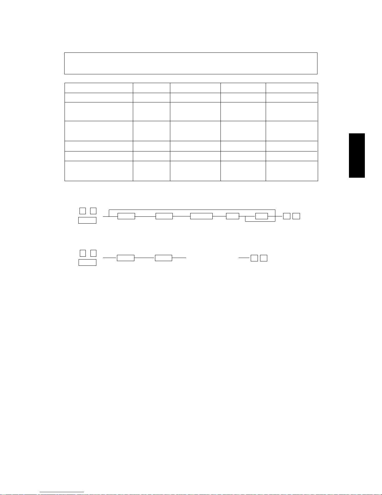
Click the Page Only button to close the overview area of the window.
Click the Bookmarks and Page button to open the Contents and
display bookmarks created for the document. Click a bookmark’s name
to go to the Page marked by that bookmark.
Click the Thumbnails and Page button to open the overview area and
display thumbnail images of each document page. Click a thumbnail to
go to the page marked by that thumbnail.
Copyright TOSHIBA CORPORATION 1995
ALL RIGHTS RESERVED

65/5560 PRECAUTIONS
1
MAY.1997 © TOSHIBA CORP.
GENERAL PRECAUTIONS REGARDING THE INSTALLATION AND
THE SERVICE OF THE 6560
1. Transportation/Installation
• When transporting the copier, move it by the casters while lifting the stoppers.
The copier is quite heavy and weighs approximately 230 kg (507 lb); therefore, pay full attention
when handling it.
2. Installation
• Be sure to use a dedicated outlet with AC 115V/15A (220V, 230V, 240V/10A) or more for the
power source.
• The copier must be grounded for safety.
Never ground it to a gas pipe or a water pipe.
• Select a suitable place for installation.
Avoid excessive heat, high humidity, dust, vibration and direct sunlight.
Also provide proper ventilation as the copier emits a slight amount of ozone.
• To insure adequate working space for copying operations, keep a minimum clearance of 80 cm
(32") on the left, 80 cm (32") on the right and 10 cm (4") in the rear.
3. Service of Machines
• Basically, be sure to turn the main switch off and unplug the power cord during service.
• Be sure not to touch high temperature sections such as the exposure lamp, the fuser unit, the
damp heater and their periphery.
• Be sure not to touch high-voltages sections such as the chargers and the high-voltage transformer.
• Be sure not to touch rotating/operating sections such as gears, belts, pulleys,etc.
• When servicing the machines with the main switch turned on, be sure not to touch live sections
such as the lamp terminal etc.
• Use suitable measuring instruments and tools.

65/5560 PRECAUTIONSMAY.1997 © TOSHIBA CORP.
2
4. Main Service Parts for Safety
• The thermofuse,thermistor,fuse,breaker and door switches,thermostat etc. are particularly important
for safety.Be sure to handle/install them properly.
5. Notice Labels
• Be sure to check the rating plate and the notice labels such as "Unplug the power cord during
service" ,"Hot area" ,etc. to see if there is any dirt on their surface or if they are properly stuck to
the copier during servicing.
6. Disposition of Consumable Parts/Packing Materials
• Regarding the recovery and disposal of the copier, supplies, consumable parts and packing
materials, it is recommended to follow the relevant local regulations or rules.
7. When parts are disassembled, reassembly is basically the reverse of disassembly unless otherwise
noted in this manual or other related documents. Be careful not to reassemble small parts such as
screws, washers, pins, E-rings, toothed washers in the wrong places.
8. Basically, the machine should not be operated with any parts removed or disassembled.
9. Precautions Against Static Electricity
• The PC board must be stored in an anti-electrostatic bag and handled carefully using a wristband,
because the ICs on it may be damaged due to static electricity.
65/5560 SPECIFICATIONS 1-1 MAY.1997 © TOSHIBA CORP
1. SPECIFICATIONS, ACCESSORIES AND OPTIONS
1.1 Specifications
1.2 Accessories
1.3 Options
1.4 System List
COSMOS
SkipOK Cancel
Texts from 1-1 to 1-5 in the
6560 Service Handbook
are the same as texts from 1-1 to 1-5 in the
6560
Service Manual
.
Do you refer to the
6560 Service Manual
?
65/5560 ADJUSTMENT MAY.1997 © TOSHIBA CORP.2-1
2. ADJUSTMENT
2.1 TOSHIBA Supplies List
COSMOS
SkipOK Cancel
Text 2-1 in the
65/5560 Service Handbook
is same as
text 20-2 in the
65/5560 Service Manual
.
Do you refer to the
65/5560 Service Manual
?
65/5560 ADJUSTMENTMAY.1997 © TOSHIBA CORP. 2-2
2.2 List of Adjustment Jigs Used
COSMOS
SkipOK Cancel
Text 2-2 in the
65/5560 Service Handbook
is same as
text 20-1in the
65/5560 Service Manual
.
Do you refer to the
65/5560 Service Manual
?
65/5560 ADJUSTMENT MAY.1997 © TOSHIBA CORP.2-3
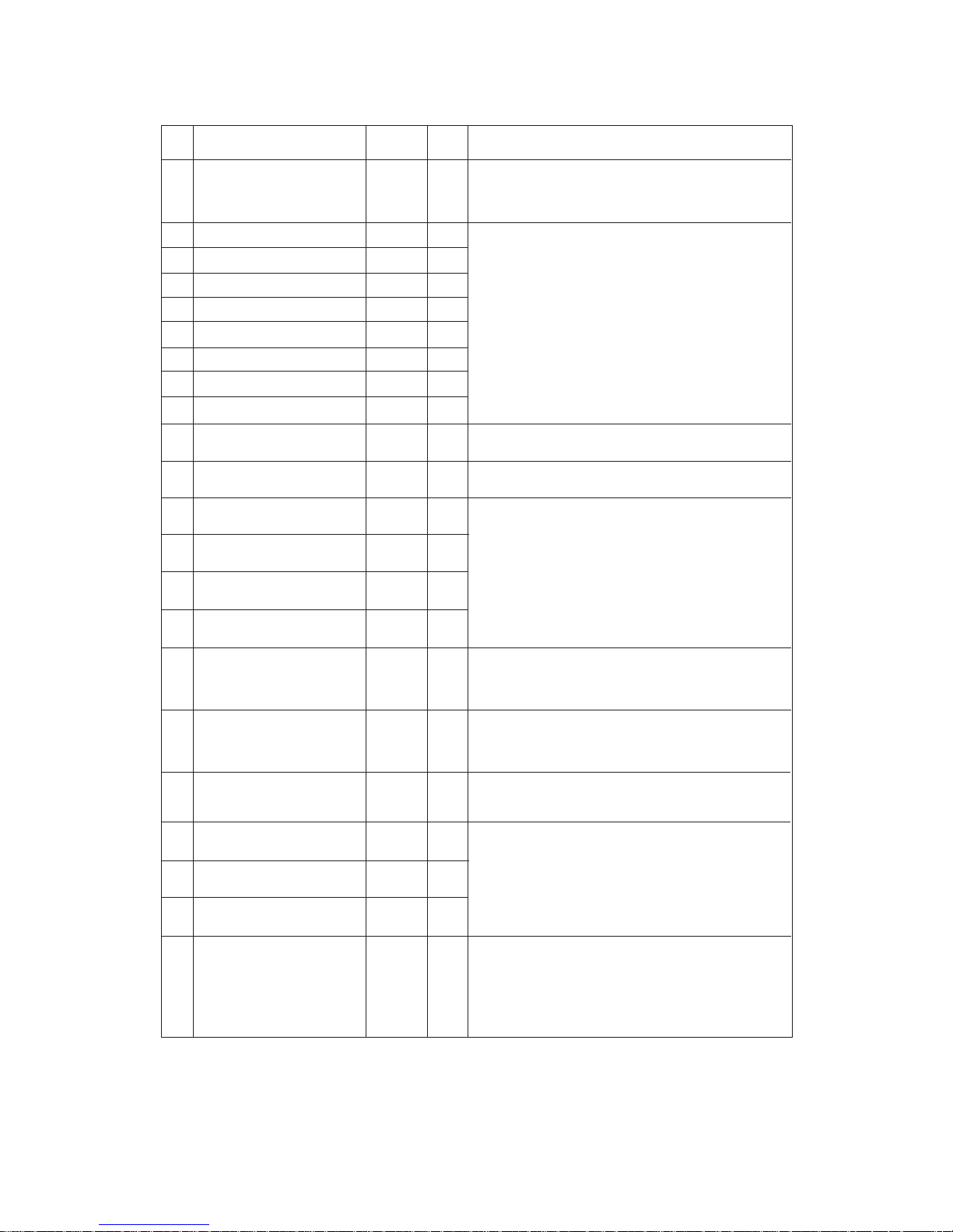
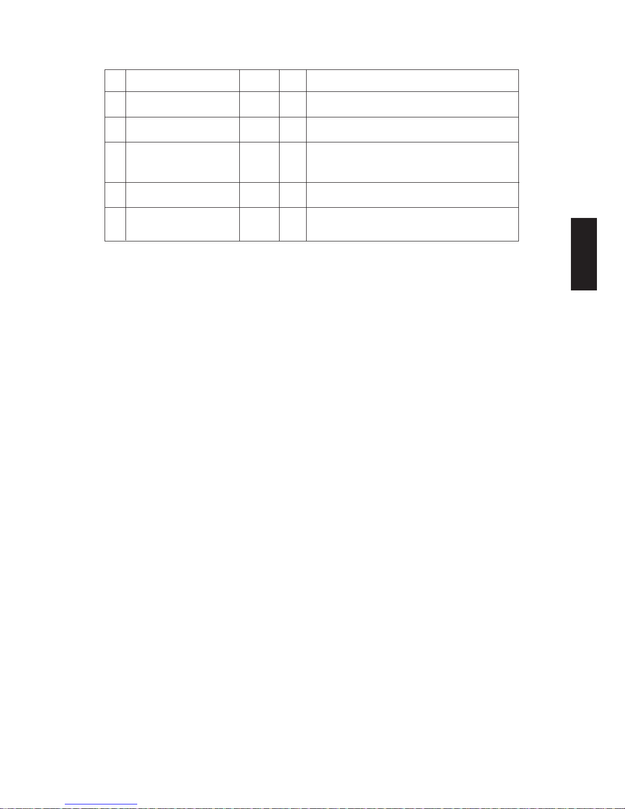
When either the CLEAR PAPER( )or CALL SERVICE( ) symbol appears,press the CLEAR/
STOP and "8"keys simuitaneously and the corresponding error code will be displayed.To clear the
error code,turn off the power.
Code Machine status
E1 Paper jam inside thr copier
E2 Paper jam near fuser unit
E3 Paper remaining inside the copier when the main switch is turned on
E4 The front cover is opened during copying
E5 Paper misfeed in LCF and manual feeding and paper jam in front of the aligning roller
E8 Paper misfeed (ADD)
E9 Paper misfeed (pedestal)
EC Paper misfeed (ADF)
ED Paper misfeed in ADF transport unit
EE Paper misfeed in ADF exit/reverse unit
C3 Abnormal serial transmission between main CPU and sub-CPU
C5 The optical system will not initialise;the optical system is locked
C7 Heat roller thermistor is open-circuited,
CB ADF feed motor locked
CC ADF transport motor locked
A0 Abnormal signal transmission in PFC interface
A1 Faulty charger wire cleaning operation
A2 ADD malfunction
A3 PFC (paper feed controller) malfunction
A4 Sorter malfunction
A5 Abnormal signal transmission between main CPU and IPC
A6 Abnormal signal transmission in sorter interface
A7 Abnormal signal transmission in ADF interface
A9 Blown exposure lamp or defective AES
2.3 Error Codes
65/5560 ADJUSTMENTMAY.1997 © TOSHIBA CORP. 2-4
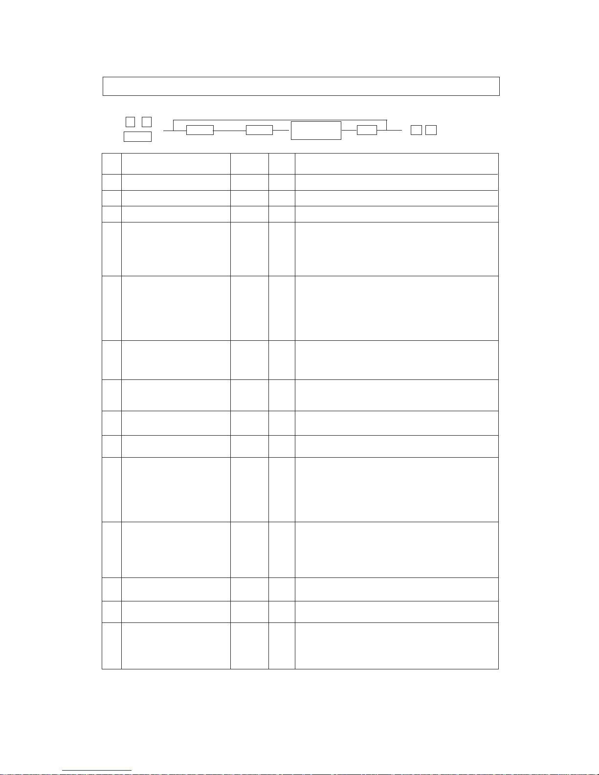
2.4 DIP Switch/Jumper/VR Functions
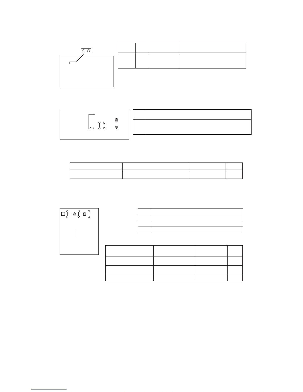
(1) Logic PC board
JP1
PWA-F-LGC-154/155
Jumper Name When shipped Remarks
JP1 UNT No jumper Jumper:Factory adjustment mode
(open) No jumper:Normal mode
Note: Replacement PC boards are supplied with the jumper
installed.
Be sure to cut it when replacing the PC boards.
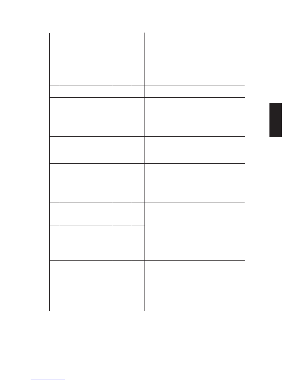
(2) Paper feed control PC board
PWA-F-PFC-154/155
JP3
(TP-SG)
VR2
VR1
R61
R60
VR FUNCTION
VR2 For adjustment ofthe paper width guide position of the
stack guide unit.
Note: Adjustoment procedure
Plus terminal of the tester Minus COM terminal of the tester Adjustment value VR
Aroow side of R60 JP3(TP-SG) 0~0.1V VR2
PWA-F-PFD-152
(TP-SG)
JP25
R39
VR2
R19
VR1
VR3
R40
(3) Paper feed drive PC board
VR Function
VR1 For adjustment of the PFP lower aligning value.
VR2 For adjustment of the PFP middle aligning value.
VR3 For adjustment of the PFP upper aligning value.
Note: Adjustment procedure
Plus teminal of the tester Minus COM terminal Adjustment value VR
of the tester
Arrow side of R19 JP25(TP-SG) 0~0.1V VR1
Arrow side of R39 JP25(TP-SG) 0~0.1V VR2
Arrow side of R40 JP25(TP-SG) 0~0.1V VR3
ë
ëë
í
í
ì
65/5560 ADJUSTMENT MAY.1997 © TOSHIBA CORP.2-5
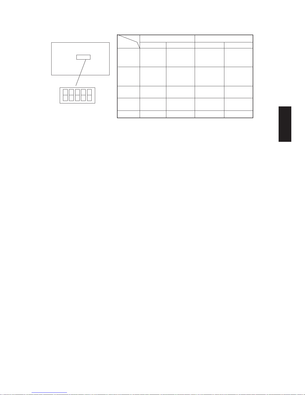
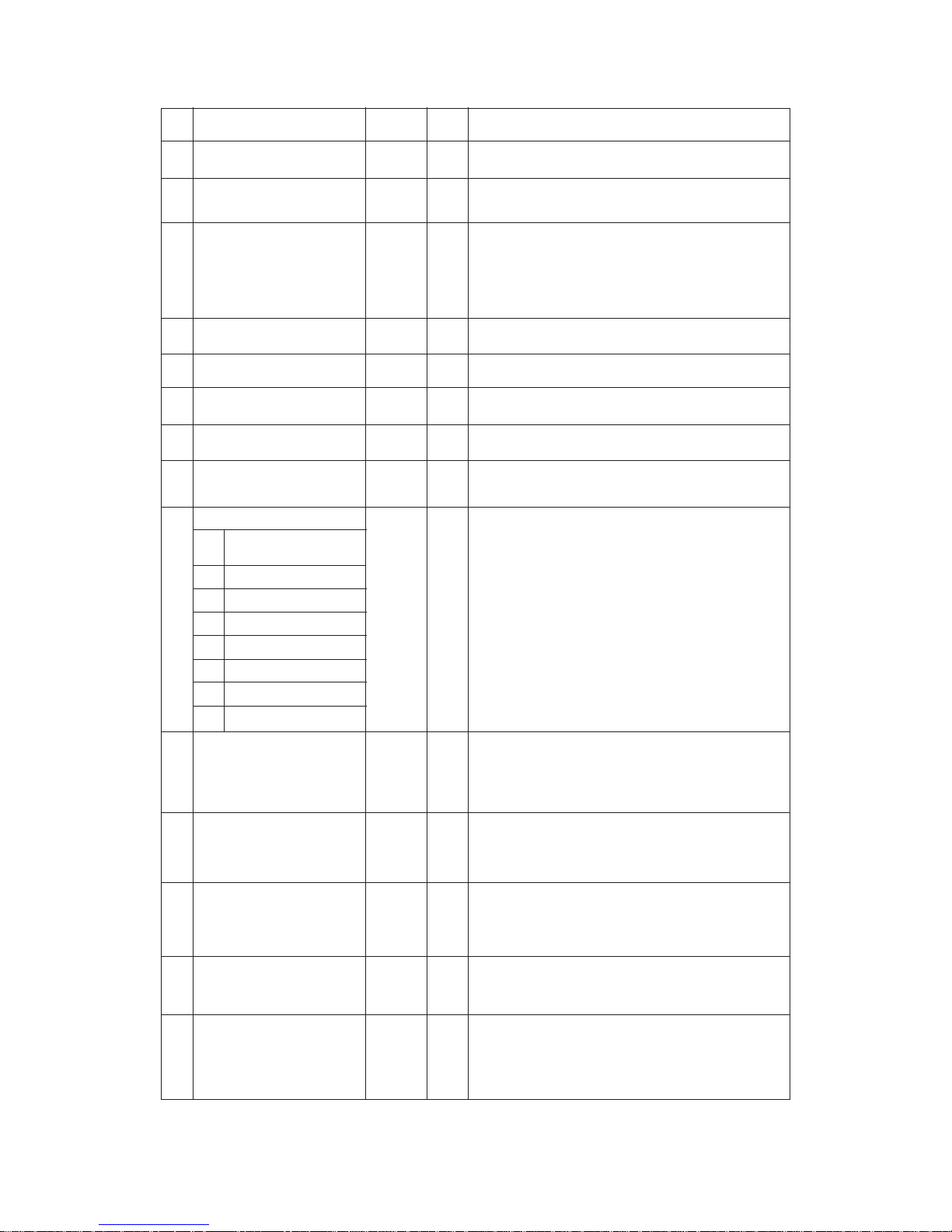
(4) ADF logic PC board
1 2 3 4 5
PWA-F-LGC-758
Note: The independent operation mode is performed as in the following procedure;set the DIP switch 1
to its ON position and turn on the power.Select the menu of the independent operation mode and
then open and close the jam release cover or the ADF cover.
↑
At power on
Duning independent operation mode
ON OFF ON OFF
1 Independent Normal mode Feeding mode Drive system
operation check mode
mode
2 Original set Original set Duplex Single-sided
by switchback by direct feeding mode feeding mode
stopping
3 USA/Canada Europe Aging mode Multifeeding
version version without paper mode
4 E2PROM Normal mode Not used Not used
initialigation
5 Not used Normal mode 2 in 1 mode OFF
DIP switch
65/5560 ADJUSTMENTMAY.1997 © TOSHIBA CORP. 2-6
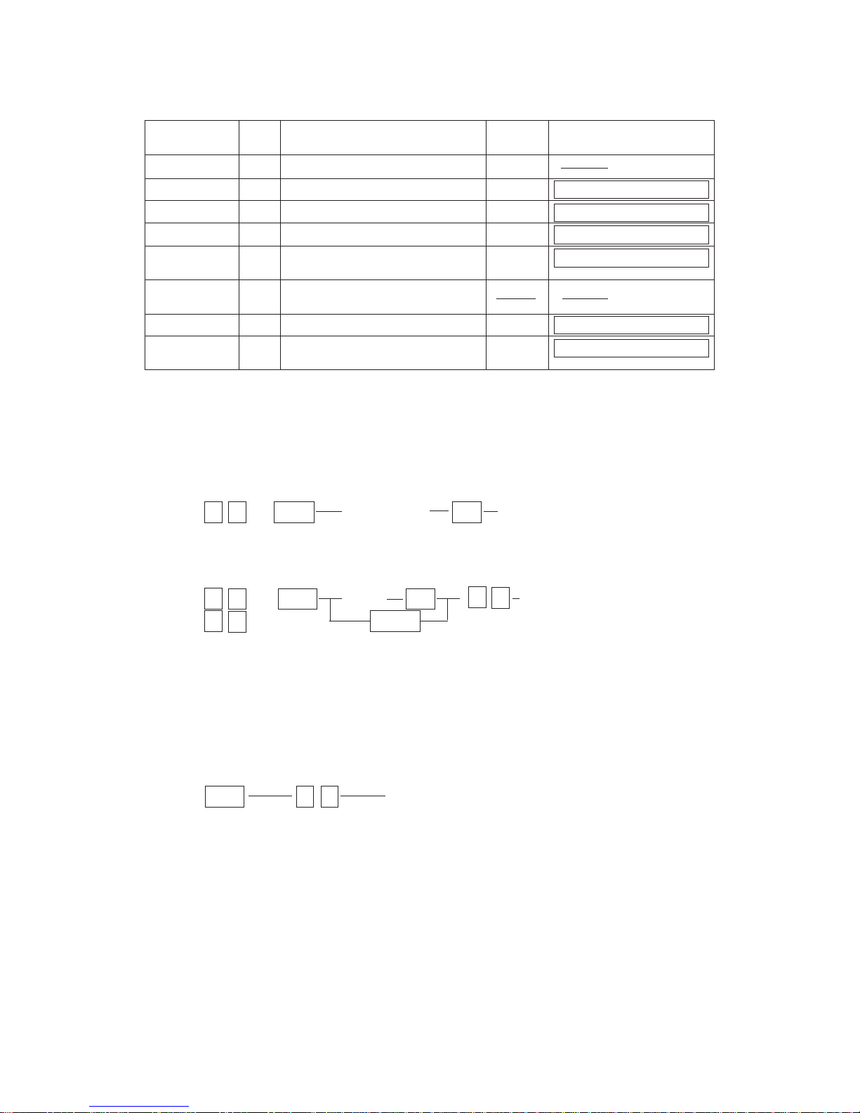
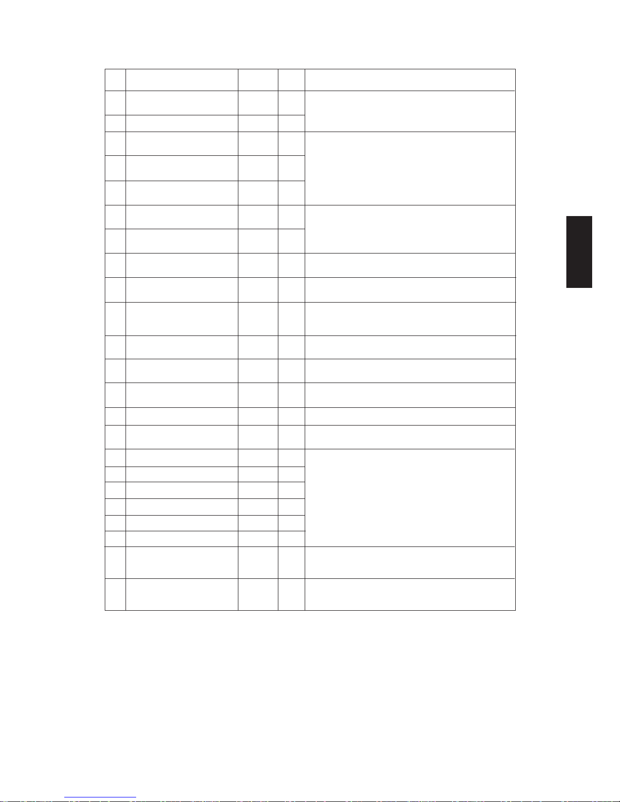
2.5 Self-Diagnosis Modes
Mode Input Definition Cleaning Display after selection
Code method
All-LEDs-lit "01" All LEDs on the control panel are lit. C/S
Aging mode "02" Aging (ADF does not operate) "09" AGING 100% 0
Test mode "03" Motor test and input/output check "09" TEST MODE C 100% C
Test mode "04" Motor test and input/output check "09" TEST MODE C 100% C
Adjustment "05" Adjustment of items "09" TEST MODE A 100% A
mode
Forced ready "06" Forced entry of ready mode
mode
Aging mode "07" Aging (includes ADF) "09" AGING 100% 0
Setting mode "08" System switchover and setting of each "09" TEST MODE D 100% D
priority mode,PM counter,etc.
Note: To access the desired diagnostic mode,turn on the power switch while pressing the appropriate
keys.
<Procedure>
•All-LEDs-lit mode(01):
0 1 / PWR All LEDs light C/S Exit
•Aging mode(02 or 07):
0 2 / PWR Aging C/S Exit
( 0 7 ) PRINT
•Test mode(03 or 04)
For these test modes,refer to 2.5.1 and 2.5.2.
•Adjustment mode(05):
For this mode,refer to"2.5.3 Adjustment Mode".
•Forced ready mode(06):
PWR 0 6 Forced ready
Note:This mode is for checking the paper feeding operation only.
•Setting mode(08):
For this mode,refer to"2.5.4 Setting mode".
Note: C/S : Press the CLEAR/STOP key
PWR: Turn on the power switch
INT : Press the INTERRUPT key
E/S : Press the ENERGY SAVER key
0 9
→
→
→
→
→→
→
→→
←
↑
65/5560 ADJUSTMENT MAY.1997 © TOSHIBA CORP.2-7
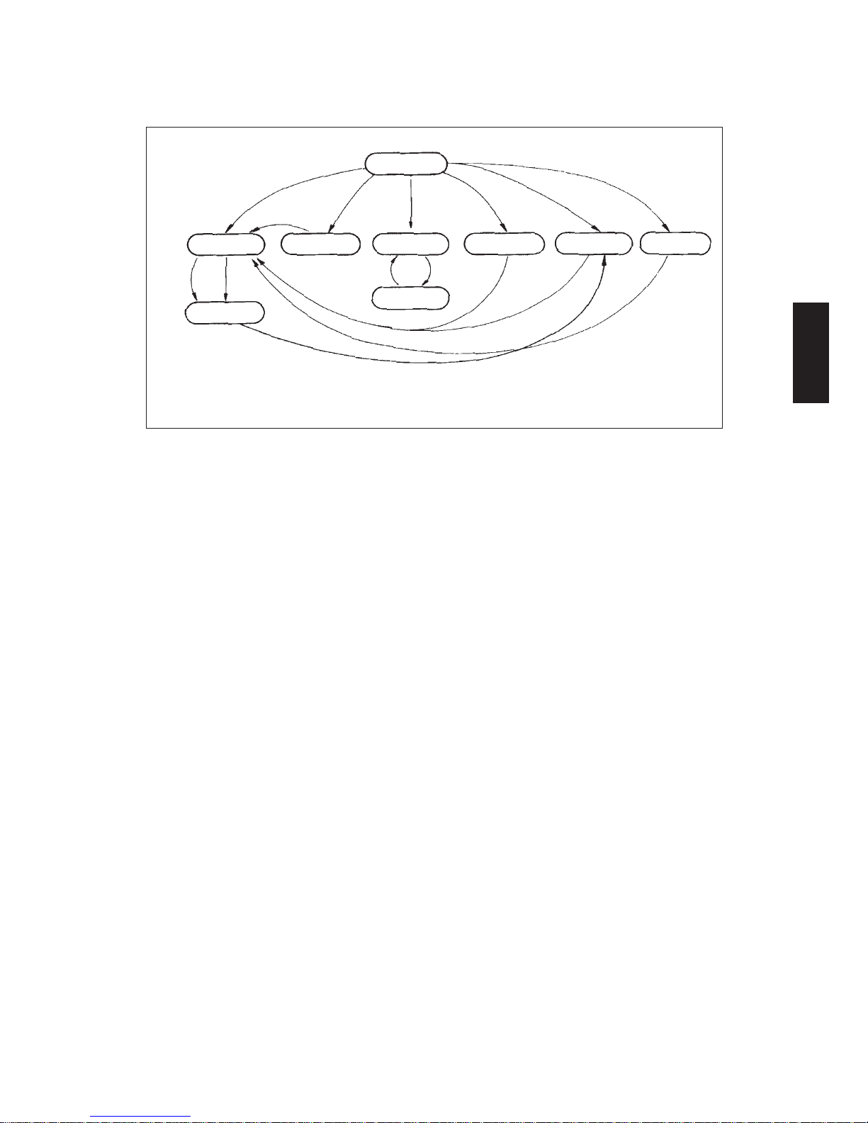
Quick reference chart for self-diagnostic mode
"P":PRINT key on.
"C":CLEAR/STOP key on.
*1: In case of "05"+
power on only
*2: Copies cannot be made
"07"
(With ADF)
"01"
*2
"02"
"C"
"06"
*1
Warming up
Standby
Aging
Test mode
All the displays on
the control panel llt
Adjustment
mode
Setting mode
"03/04"
"05"
"08"
Power On
"09"
"C""P"
"09"
"09"
"05"
Stops momentarily
65/5560 ADJUSTMENTMAY.1997 © TOSHIBA CORP. 2-8
BVD1
Battery
living
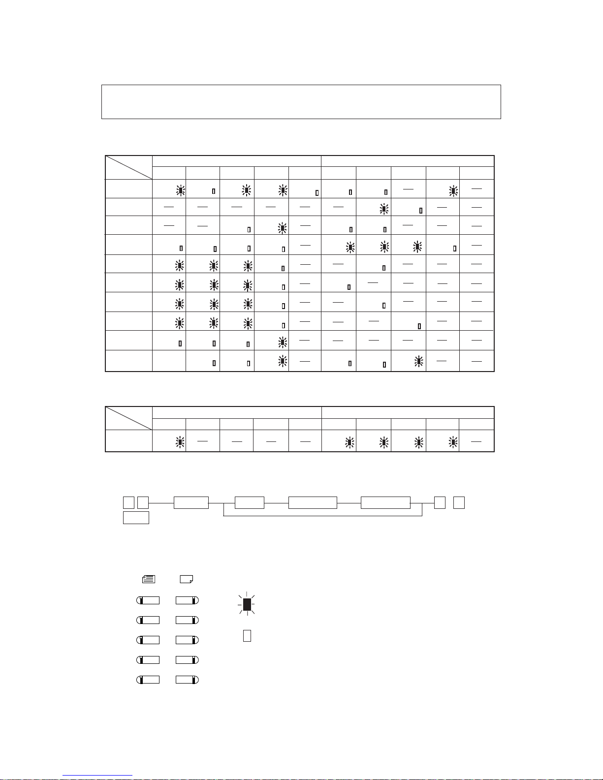
2.5.1 Input Signal Check (03/04)
In the "03" or "04" test mode, the following input signal conditions can be checked by pressing the
appropriate keys.
Note:*:Only for machines which have an optional IC card installed
lWhen automatic exposure is selected
(1)key
(2)key
(3)key
(4)key
(5)key
(6)key
(7)key
(8)key
(9)key
ADD-PEM-SW
Paper
loaded
EMP2-SW
Paper
loaded
EMP3-SW
Paper
loaded
EMP4-SW
Paper
loaded
TUP4-SW
Top
position
GUIDE-HOME-SW
Home
position
TUP2-SW
Top
position
TUP3-SW
Top
position
ADD-STP-SW
Paper
loaded
PSTP2-SW
Paper
loaded
PSTP3-SW
Paper
loaded
PSTP4-SW
Paper
loaded
T-DWN-SW
Bottom
position
R-DOOR-SW
Opened
WP
Write
protect
TNR-HOP-SW
Opened
HOME-SW
Home
position
LNS-SW
Home
position
EXIT-SW
Paper
loaded
L-DOOR-SW
Opened
M-FEED-SW
Paper
loaded
ADD-JAM-SW
Paper
loaded
TNR-EMP-SW
Toner empty
CLN-T-SW
On
APS-C
Paper loaded
APS-F
Paper loaded
STP-HOME-SW
Home
position
FEED2-SW
Paper loaded
FEED3-SW
Paper loaded
FEED4-SW
Paper loaded
LCF-EMP-SW
Paper loaded
T-UP-SW
Top position
ADD-STR-SW
Paper loaded
P-STP-SW
Paper
loaded
LCF-FEED-SW
Paper
loaded
CNT(JPI)
Connected
CTRSIG
Connected
DF-CNT
Connected
CST2-SW
Cassette
loaded
LCFDOOR
Closed
CST3-SW
Cassette
loaded
MRR-SW
On
CLN-M-SW
ON
DEV-SW
Connected
CD
IC card
lWhen manual exposure is selected
REG-SNS
Paper
loaded
EMP-SNS
Paper
loaded
SIZE-SNS
Paper
loaded
TURN-SNS
Paper
loaded
DF-OPN-SW
COVER-SW
Opened
(1)key
(0)key
Original-size LEDCopy-size LED
A4/LD A3/LG B4/LT A5/ST A4/LD A3/LG B4/LT A5/ST
A4/LD A3/LG B4/LT A5/ST A4/LD A3/LG B4/LT A5/ST
Original-size LEDCopy-size LED
Indicator
LEDkey
Operation
Indicator
LEDkey
Operation
BVD2
Battery's
life
T-FUL-SW
Toner full
APS-STR-SW
Closed
CST4-SW
Cassette
loaded
LCFKEY
On
LCF
LCF loaded
∗
∗∗
∗
UNIVERSAL/
OTHER
UNIVERSAL/
OTHER
<Procedure>
0 3 PRINT EXP Digital key PWR OFF 0 9
PWR (To clear)
Note: 03 →With initialization before test mode is entered
04 →Without initialization
(
→→
→
→
↑
→
A4
(LD)
ORIGINAL COPY
A3
(LG)
B4
(LT)
A5
(ST)
UNIVERSAL
(OTHER)
means that when the particular key is pressed and the
condition shown exists,the LED will light.(Input signal is "H" level)
means that the LED does not light if the condition shown
exists.(Input signal is "L"level)
•
•
UNIVERSAL/
OTHER
UNIVERSAL/
OTHER
65/5560 ADJUSTMENT MAY.1997 © TOSHIBA CORP.2-9
2.5.2 Output Signal check (03/04)
In the "03"or"04"test mode,the folloeing output signal conditions can be checked by entering appropiate
codes.
Code Function Stop code
1 DRM-MOT ON 11 OFF
2 FED-MOT ON 12 OFF
3 RGT-MOT ON 13 OFF
4 HTR-MOT ON 14 OFF
5 DEV-MOT ON 15 OFF
6 TNR-MOT ON 16 OFF
7 OPT-FAN-MOT HIGH 17 LOW
8 EXIT-FAN-MOT HIGH 18 LOW
9 AUG-MOT ON 19 OFF
41 ADD-FED-MOT ON 51 OFF
42 ADD-RGT-MOT(Stack) ON 52 OFF
43 ADD-RGT-MOT(Feed) ON 53 OFF
61 PD-MOT ON 71 OFF
62 FD2-CLT
FD3-CLT ON 72 OFF
FD4-CLT
63 RGT2-CLT
RGT3-CLT ON 73 OFF
RGT4-CLT
65 DEV-FAN ON 75 OFF
67 BTM-FAN HIGH 77 LOW
68 CH-FAN
HTR-FAN
ON 78 OFF
20 SCN-MOT
21 LNS-MOT
22 MRR-MOT
23 CLN-MOT
24 DCM-MOT
25 CLN-TR-MOT
Changes direction
26 TRAY-MOT(LCF)
each time the PRINT
45 STOP-MOT
key is pressed
.
46 GUIDE-MOT
64 TR2-MOT(PFP)
TR3-MOT(PFP)
TR4-MOT(PFP)
*8
Group3
Code Function
30 HV-M ON/OFF
(Main charger output)
31 HV-TR ON/OFF
(Transfer charger output)
32 HV/AC ON/OFF
(Transfer charger output)
33 EXP-LAMP ON/OFF
34 GBIAS ON/OFF
(Transfer bias output)
35 PRE-TR-C4 ON/OFF
37 SCRP-SOL ON/OFF
38 MANUAL-SOL ON/OFF
48 ADD-SOL ON/OFF
49 GATE-SOL ON/OFF
81 ADF-FEED-MOT(CW) ON/OFF
82 ADF-FEED-MOT(CCW) ON/OFF
83 ADF-CLU ON/OFF
ADF-BELT-MOT(CW)
84 ADF-CLU ON/OFF
ADF-BELT-MOT(CCW)
85 ADF-FEED-MOT(CCW) ON/OFF
ADF-BELT-MOT(CW)
ADF-CLU
86 STP-SOL
FLP-SOL ON/OFF
ADF-CLU
BRKE
*1
*2
*2
Group1
*3
*4
*5
*6
*7
Group2
*1 The feed motor will rotate in the direction appropriate for the cassette loaded at the time of the output signal
check.
*2 For FD2~4-CLT and RGT2~4-CLT,the clutch appro priate for the cassette loaded at the time of the output signal
check will be driven.
*3 The scanning motor will run at the correct speed for the reproduction ratio selected(and displayed)at the time of
the output signal check.
*4 The tray motor moves the tray up when the PRINT key is pressed once,and is turned off when the tray-up switch
is turned on.When the PRINT key is pressed a second time,it moves the tray down and is turned off when the
tray-down switch is turned on.
*5 The length guide motor performs initalisation when the PRINT key is pressed once.When the PRINT key is
pressed a second time, it moves the paper length guide to the widest setting position and then is turned off.When
the PRINT key is pressed a third time,it moves the paper length guide in for a narrow setting and is turned off
when the length guide home switch is turned on.
*6 The width guide motor widens the paper width guide when the PRINT key is pressed once and is turned off when
the width guide home switch is turned on.When the PRINT key is pressed a second time,it narrows the paper
width guide until the A4-R size position and then is turned off.When the PRINT key is pressed a third time,it,widens
the guide until the A3 size position and is turned off.
*7 For TR2 to 4-MOT,the motor appropriate for the cassette loaded at the time of output signal check is chosen.When
the PRINT key is pressed once, the motor moves the tray up and is turned off when TUP2 to 4-SW is turned
on.When the PRINT key is pressed a second time,it moves the tray down and is turned off after a set time lag.
*8 The exposure lamp stays on for 5 sec.and then goes off automatically.
65/5560 ADJUSTMENTMAY.1997 © TOSHIBA CORP. 2-10
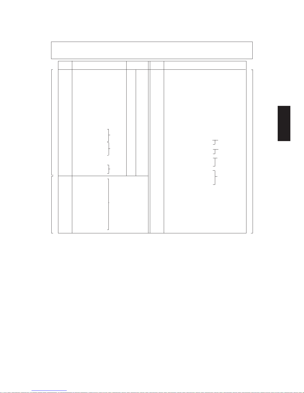
<Procedure>
Group(1)
0 3 / 0 4 Operation Stop
PWR (ON) Code
Group(2)
0 3 / 0 4 Operation C/S Test mode standby
PWR (one-way) 0 9 Warm-up
Group(3)
0 3 / 0 4 Operation Operation C/S
PWR (ON) (OFF) 0 9 Warm-up
Code PRINT PRINT 0 9 Warm-UP
Code PRINT
Code PRINT PRINT
Test mode
standby
↓
↓↓
↓
↓
→→→ →
→
→→
→→ →
→
→
→
→
→
→
→
→
→
→→
→
→
65/5560 ADJUSTMENT MAY.1997 © TOSHIBA CORP.2-11
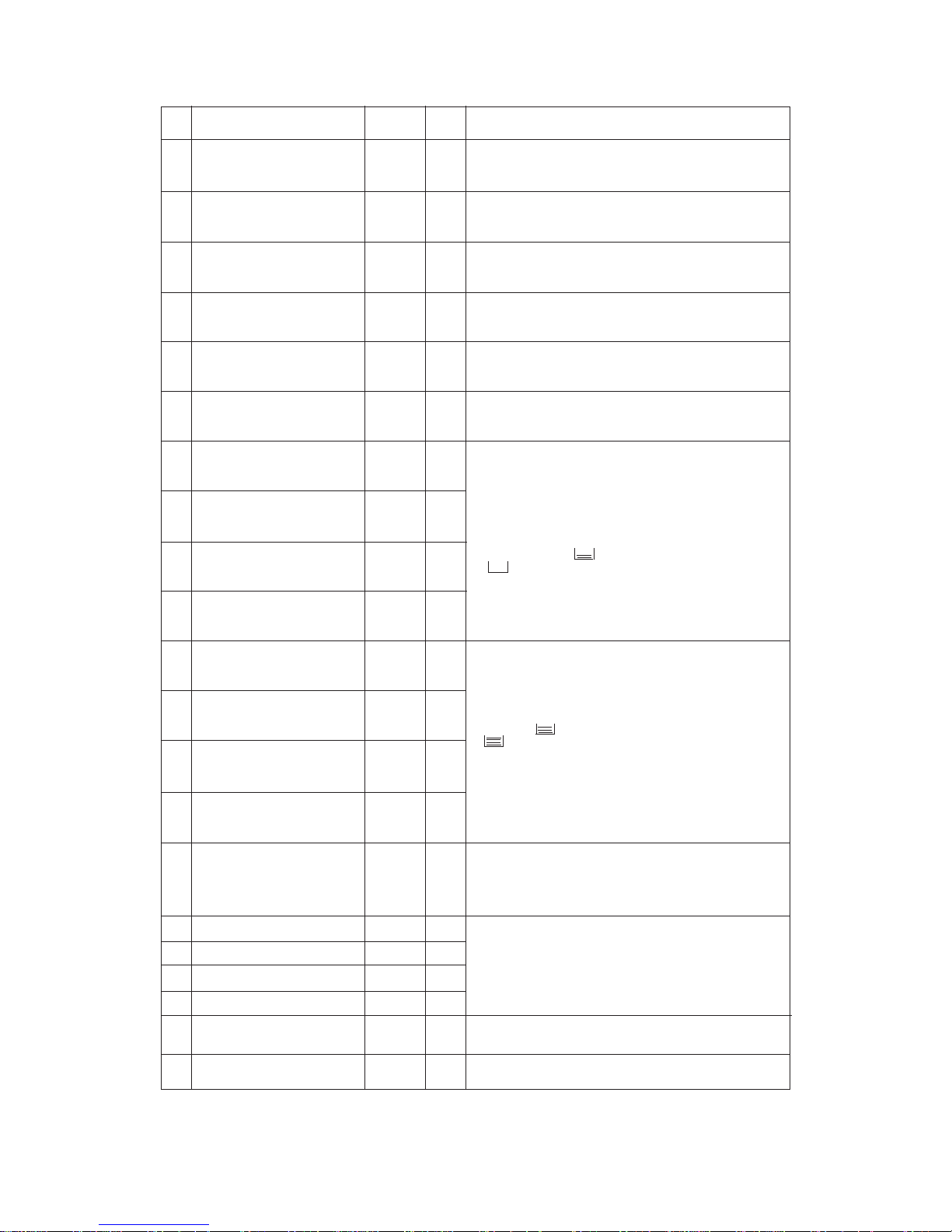
Adjustment item Code Keys to adjust with keys to store with Remarks
Auto-toner sensor 0 Zoom keys INTERRUPT See 2.6 for details.
Exposure 1~10 Digital keys/ INTERRUPT See 2.7 for details.
14~17 ZOOM keys
*Automatic adjustment 49 Not needed Not needed See 2.7 for details.
for exposure
HVT output 38~40,41,44 ZOOM keys INTERRUPT See 2.10 for details.
Registration 53~58 Digotsl keys INTERRUPT See 2.8.5 for details.
Other adjustment Except for Digital keys INTERRUPT Refer to Adjustment
above codes code list
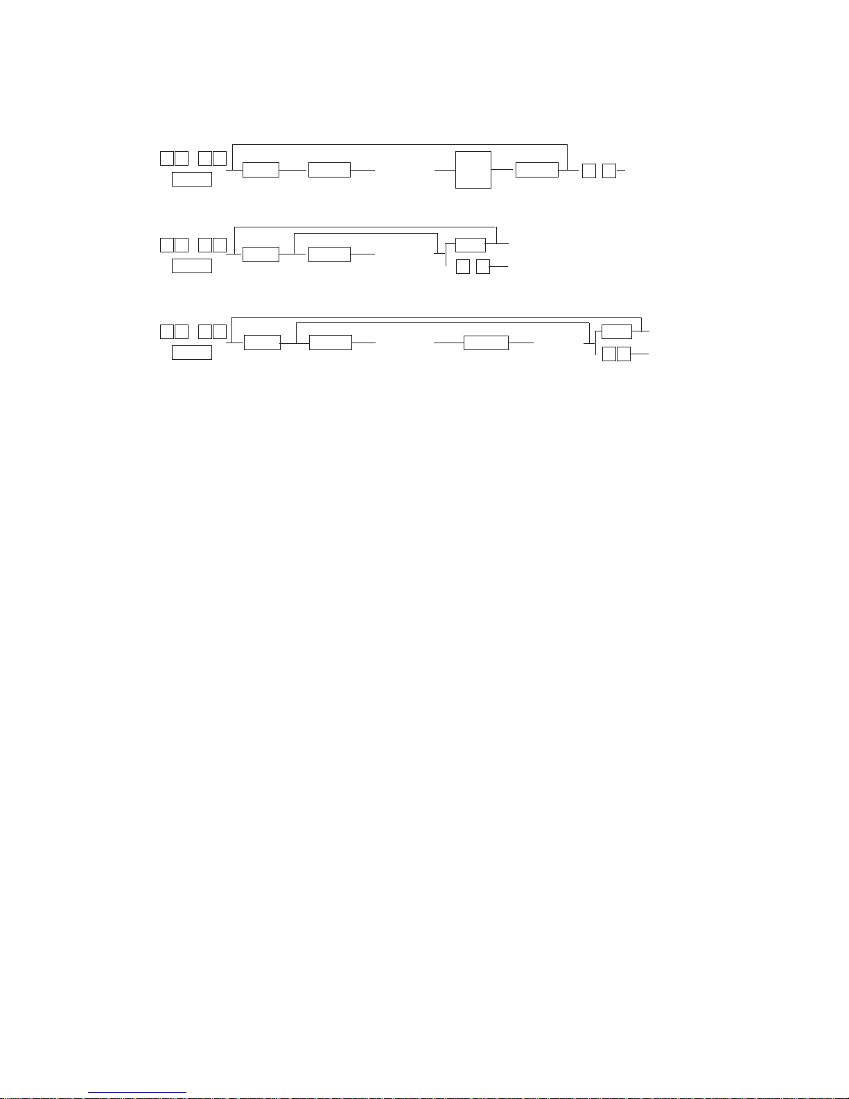
0 5
PWR
Code PRINT ADJUST INT E/S 0 9
0 5
PWR
49 PRINT 0 9
Automatic adjustment
for automatic exposure
<Procedure>
Exit
Test copy
Exit
↓
→
→
→→→
→
→→→→
↑
∗
2.5.3 Adjustment Mode (05)
In this mode,the following adjustment items can be corrected or changed(see the Adjustment Code
List for "05"Mode). To access this code,turn on the power while pressing the "0"and"5"keys.
Memory set
65/5560 ADJUSTMENTMAY.1997 © TOSHIBA CORP. 2-12
Adjustment Code List ("05")
•The larger the value,the larger the sensor output,
•About 3 minutes after this mode has been started,this
value changes automatically to make the sensor output
2.45V~2.55V.
•The larger the value,the lighter the image.
•The adjustment sequence must be
1→2→3→4→5→6→7→8→9→10.
The larger the value,the lighter the light range.
The smaller the value,the darker the dark range.
•The larger the value,the lighter the image.
•The adjustment sequence must be 14→15→16→17.
Each time the numerical value is increased by "1",the
reproduction ratio in the movement direction increases
by approximately 0.15%.
Range;-1.17%(reduction)to +1.05%(enlargement)
Each time the numerical value is increased by"1",the
reproduction ratio in the movement direction increases
by approximately 0.10.
Range:-0.77%(reduction)to +0.69%(enlargement)
Each time the numerical value is increased by"1",the
heat roller motor speed increases by 0.06%.
Range:-0.75%(reduction)to +0.71%(enlargement)
Each time the numerical value is increased by "1",the
image shift moves 0.5mm toward the trailing edge of
the paper without changing the position of the image
relative to the paper.
Motor ratings can be adjusted by the following ranges:
0:-1.19% 1:-1.03%
2:-0.88% 3:-0.73%
---------- ----------
---------- 13:+0.76%
14:+0.91% 15:+1.06%
Code
Name
Allowable Initial
No.
Input values Value*
0 Auto-toner sensor 0~255 128
1 Manual exposure(100%) 0~255 128
2 Manual exposure(154%) 0~255 128
3 Manual exposure(50%) 0~255 128
4 Manual exposure(200%) 0~255 128
5 Manual exposure(100%) 0~255 128
6 Manual exposure(154%) 0~255 128
7 Manual exposure(50%) 0~255 128
8 Manual exposure(200%) 0~255 128
9 Allowable exposure step 0~255 128
range(light)
10 Allowable exposure step 0~255 128
range(dark)
14 Manual photo exposure 0~255 128
(100%)
15 Manual photo exposure 0~255 128
(154%)
16 Manual photo exposure 0~255 128
(50%)
17 Manual photo exposure 0~255 128
(200%)
20 Aligning roller speed 0~15 10
adjustment
21 Drum speed adjustment 0~15 12
22 Heat roller speed adjustment 0~15 8
25 Leading edge of image shift 0~15 8
(100%)
26 Leading edge of image shift 0~15 8
(200%)
27 Leading edge of image shift 0~15 8
(50%)
28 PFP motor speed 0~15 8
Contents
*The initial value means the one that is set by the BC-RAM initialize program, and does not mean the one set at the
factory before shipment.
65/5560 ADJUSTMENT MAY.1997 © TOSHIBA CORP.2-13
Contents
Each increase by"1"will move the editing position 0.5mm
toward the trailing edge of the paper(feed
side).Adjustment should be made in the order of
32→33→34.
Each time the numerical value is increased by"1",only
the void moves 0.5mm toward the trailing edge of the
paper.
The larger the value,the higher the output.(Not
necessary to adjust)
The larger the value,the higher the output.
The larger the value,the higher the output.
The larger the value, the higher the output.
When the numerical value is increased, the output
increases
The lager the value, the higher the separation DC
welghted output.
The larger the value, the brighter the LCD panel.
Automatically adjusts the automatic exposure based on
the manual exposure.
Each time the unmerical value is increased by "1",the
image advances approximately 0.8mm toward the
leading edge.The adjustment sequence is
53→54→55→56→57→58.
Each time the numerical value is increased by "1",the
lens moves approximately 0.2mm toward the
enlargement direction.
Each time the numerical value is increased by "1",the
lens moves approximately 0.1mm toward the
enlargement direction.
Each increase by "1" will move the edge erasing position
or the leading (trailing) edge of the paper 0.5mm toward
the trailing edge of the paper.
Code
Name
Allowable Initial
No.
Input values Value
30 Leading edge of edge 0~15 8
erasing
31 Trailing edge of edge erasing 0~15 8
32 Editing position adjustment 0~15 8
(100%)
33 Editing position adjustment 0~15 8
(200%)
34 Editing position adjustment 0~15 8
(50%)
35 Leading-edge void adjust- 0~15 8
ment
36 Trailing-edge void adjust- 0~15 8
ment
38 Main charger output 0~255 128
39 High-voltage transformer 0~255 128
(transfer)output
40 High-voltage transformer 0~255 128
(separation/developer bias)
output
41 Pre-transfer discharger 0~255 128
transformer output
42 Main charger output 0~255 205
(photo mode)
44 Separation DC output 0~255 185
45 LCD contrast adjustment 0~255 150
49 Automatic adjustment for - -
automatic exposure
53 Registration(LCF/100%) 0~15 8
54 Registration(LCF/200%) 0~15 8
55 Registration(LCF/50%) 0~15 8
56 Registration(manual/100%) 0~15 8
57 Registration(PFP/100%) 0~15 8
58 Registration(ADD/100%) 0~15 8
60 Lens position(100%) 0~99 50
61 Mirror position(100%) 0~99 50
65/5560 ADJUSTMENTMAY.1997 © TOSHIBA CORP. 2-14
Code
Name
Allowable Initial
No.
Input values Value
62 Lens position(200%) 0~99 50
63 Mirror position(200%) 0~99 50
64 Lens position(50%) 0~99 50
65 Mirror position(50%) 0~99 50
68 Automatic adjustment of – –
remaining paper quantity
indication(no paper loaded)
69 Automatic adjustment of – –
remaining paper quantity
indication( paper loaded)
70 Remaining paper quantity 0~31 3
indication(LCF/no paper
loaded)
71 Remaining paper quantity 0~31 2
indication(upper cassette
/no paper loaded)
72 Remaining paper quantity 0~31 2
indication(middle cassette/
no paper loaded)
73 Remaining paper quantity 0~31 2
indication(lower cassette/
no paper loaded)
74 Remaining paper quantity 0~31 4/3**
indication(LCF/ paper
loaded)
75 Remaining paper quantity 0~31 2/3**
indication(upper cassette
/paper loaded)
76 Remaining paper quantity 0~31 4/8**
indication(middle cassette/
paper loaded)
77 Remaining paper quantity 0~31 7/3**
indication(lower cassette/
paper loaded)
79 Carriage control of the 0~2 –
leading edge of the image
80 Aligning value(LCF) 0~15 8
81 Aligning value(manual) 0~15 8
82 Aligning value(PFP) 0~15 7
83 Aligning value(ADD) 0~15 7
84 ADF aligning value(1st 0~15 8
page)
85 ADF aligning value(2nd 0~15 8
page)
Contents
Each time the numerical value is increased by "1",the
lens moves approximately 0.2mm toward the
enlargement direction.
Each time the numerical value is increased by "1",the
lens moves approximately 0.1mm toward the
enlargement direction.
Each time the numerical value is increased by "1",the
lens moves approximately 0.2mm toward the
enlargement direction.
Each time the numerical value is increased by "1",the
lens moves approximately 0.1mm toward the
enlargement direction.
Remove all of the paper from the LCF and PFP cassettes
when the adjustment is performed.
Install 4,000 sheets of paper in the LCF and the 500
sheets of paper in each of the PFP cassettes when the
adjustment is performed.
These adjustments are made manually when the
remaining paper quantity becomes down to half or less.
After the adjustment of code 68 is performed,conduct
these adjustments if necessary.
In case the variational ratio of the remaining paper
quantity indication is slower than the decrease ratio of
the actual quantity of sheets of paper,increase the
numerical value.
(Example)When" "symbol suddenly changes to
" "symbol.
These adjustments are made manually when more than
half of the paper remains.After the adjustment of code
69 is perfomed,conduct these adjustments if necessary.
In case the remaining paper quantity indication is
displayed as greater than the actual quantity of sheets
of paper,increase the numerical value.
(Example)" "symbol should be actually displayed,but
" "symbol is displayed.
**LT series/A4 series
0:Normal control
1:To slow down the acceleration to the leading edge of
the image.
2:To increase the pre-scanning amount to the leading
edge of the image.
Each time the numerical value is increased by"1",the
amount of slack increases by approximately 1.9 mm.
Each time the numerical value is increased,the original
moves toward the paper feed side.
Each time the numerical value is increased,the original
moves toward the exit side(original stopper side).
**Europe (A4 series) / U.S.A. and Canada (LT series)
65/5560 ADJUSTMENT MAY.1997 © TOSHIBA CORP.2-15
Each time the numerical value is increased by "1", the
amount of slack increases by approximately 1.9 mm.
Each time the numerical value is increased, the gap
between originals increases.
Each time the numerical value is increased, the original
shifts to the paper supply side on the copier (that is,
moves away from the original stopper). This is carried
out after adjustment "87"(ADF aligning value).
The auto-toner adjustment value is indicated.
This value can be changed.
0~31 :Negative calibration:Max.-5.35sec./month/step
32~63:Positive calibration:Max.+10.7sec./month/step
0,32 :Correction deactivated
Code
Name
Allowable Initial
No.
Input values Value
86 Aligning value 0~15 7
(long size paper/upper cassetle)
87 ADF aligning value 0~15 8
(2in1 original gap)
88 ADF leading edge position 0~15 8
(in 2in1 mode)
90 Auto-toner sensor 0~255 128
adjustment value
99 Real-time clock adjustment 0~63 0
Contents
65/5560 ADJUSTMENTMAY.1997 © TOSHIBA CORP. 2-16
Code
Name
Allowable Initial
No.
Input values Value*
0 Date/time input 13digits 1 Date indication 0~3 2
2 Time indication 0,1 0/1**
4 Auto sort mode 0~3 0
5 Automatic duplex mode 0~3 0/1**
6 Setting temperature of the 0~15 0
heat-roller surface
7 Access control mode active 0~2 0
8 Version change 0~2 0/1**
9 Actual-size reproduction 0,1 0
ratio
10 Timer mode 0~10 3
11 Auto power saving 0~12 0/3**
12 MAX9 0~2 0
13 Paper-feed retrial 0,1 0
14 Cassette priority selection 0~4 1
Code PRINT INT 0 9
2.5.4 Setting Mode (08)
Clear
In thismode, the various special modes listed in the Setting Code List can be set or changed.
<Procedure>
0 8
PWR
Ste/change
a value
Memorize
Contents
Year/month/date/day/hour/minute/second
(Example)0:5/25 1:25/5 2:25.May 3:25.May
(Example)0:15:30 1:PM 3:30
The sort mode is selected automatically when the
original is placed on the ADF.
0: Deactivated
1: Staple sort
2: Sort
3: Group
The duplex mode is selected automatically when the
original is placed on the ADF.
0: Deactivated
1: (single-sided to dual-sided) is selected
2: (dual-sided to dual-sided) is selected
3: (dual-sided to single-sided) or (single-sided to dual sided) is selected according to the message.
0:200°C 1:197°C 2:199°C 3:200°C 4:202°C 5:204°C
6:206°C 7:208°C 8:210°C 9:212°C 10:214°C 11:216°C
12:218°C 13:221°C 14:223°C 15:224°C
∗Never set to a value of 8 or more.
0: Access control mode deactivated
1: Access control mode activated(copier)
2: Access control mode activated(IC card)
0: EUR(A4/A3/FOLIO),1:UC(LT/LD)
2: JPN(A4/B4)
0: 100%,1:101%
If there is no control panel operation during the ready
status for a certain length of time as shown below,the
copy-mode automatic resetting function is performed.
Resetting operation start time is:
1: 15 sec.,2: 30 sec.,3: 45 sec.,4: 60 sec.,----10: 150 sec.
0: Deactivates the copy-mode automatic resetting.
Auto power saving operates n minutes after ready status
is reached.The functions are:
0: Deactivated
1: After 5 minutes
2: After 10 minutes
n: After n ×5 minutes
Copy quantity
0: max.999,1:max.9,2:max.99
0: Feed-retrial mode
1: No-feed-retrial mode
0: A4/LT priority
1: LCF priority
2: Upper cassette priority
3: Middle cassette priority
4: Lower cassette priority
↓
→→→ →
→
*The initial value means the one that is set by the BC-RAM initialize program, and does not meaus the one set at the factory
before shipment.
**Europe(A4 series)/U.S.A.and Canada(LT series)
***This selection is made only when the FC key is pressed or when auto-resetting works.
***
65/5560 ADJUSTMENT MAY.1997 © TOSHIBA CORP.2-17
Code
Name
Allowable Initial
No.
Input values Value
15 Exposure priority selection 0~2 0
16 A3 double count 0,1 0
17 Manual-feed auto-start 0,1 0
18 ADF mode selection 0,1 0
19 Sort mode selection 0~3 0
20 Edge erasing priority 0~2 0
selection
21 Automatic cassette 0,1 1
selection
22 APS priority selection 0,1,2 1
23 Detection of manually placed 0,1 0
original
24 APS start timing 0~15 5
27 ADF¥APS mode 0,1 0
31 Paper size(LCF) 0~15 3/4**
32 Paper size(upper cassette) 0~15 6/7**
33 Paper size(middle cassette) 0~15 11/14**
34 Paper size(lower cassette) 0~15 13/4**
38 Upper heater setting during 0~9 0
energy saving
39 Selection of paper size
enabled by cassette key 0~2 0
43 Resettable counter display, 0~3 0
original counter display
46 Toner save mode 0.1 1
Contents
0: Auto exposure priority
1: Manual exposure priority
2: Photo exposure priority
3: Toner save priority
0: Single count
1: Double count
0: PRINT key starting
1: Auto-start
0: ADF mode
1: SDF mode
The mode selected when power is turned ON
0: Non sort
1: Staple sort
2: Sort
3: Group
0: Deactivated
1: Edge erasing priority
2: Automatic edge erasing priority
0: Deactivated
1: Activated
0: Deactivated
1: APS priority
2: AMS priority
Detects manually placed original
0: Deactivated
1: Activated
0: 0 sec.,1: 100 msec,2: 200 msec
n: n×100 msec
0: Detection of every sheet of paper
1: Detection of only the first sheet
1: A5-R 2: ST-R/B5
3: LT 4: A4
5: B5-R 6: LT-R
7: A4-R 8: Sheet insertion
9: Cover seet 10: COM/FOLIO
11:LG 12: B4
13: LD 14: A3
**LT series/A4 series
0: 190°C 5: 160°C
1: Heater off 6: 170°C
2: 130°C 7: 180°C
3: 140°C 8: 190°C
4: 150°C 9: 200°C
0: Enabled
1: Not allowed
2: Cover sheet and sheet insertion only enabled
0: Deactivated
1: Resettable counter only displayed
2: Original counter only displayed
3: Resettable counter and original counter displayed
0: Deactivated
1: Selectable with IMAGE/PHOTO Key
2: Activated
**Europe(A4 series)/U.S.A.and Canada(LT series)
65/5560 ADJUSTMENTMAY.1997 © TOSHIBA CORP. 2-18
0: Activated at all times
1: Activated only at automatic exposure
2: Deactivated
Auto shut-off to force when it was left for a following
contorol time (Same OFF state as weekly Timer)
0:3 1:5 2:10 3:15 4:20 5:25
6:30 7:40 8:50 9:60 10:70
11:80 12:90 13:100 14:110 15:20
16:150 17:180 18:210 19:240(min)
20:
∞
Other than 0: PM call when set value ≤ Copy count
(code"79")
Current copy quantity
Telephone numbers of up to 14 digits can be
entered.Use the HELP key to enter hyphens(min.).
0: Normal
1: LCF forced paper OFF state (LCF tray does not move)
Heat-roller thermistor breakdown counter
0~2:Normal operation
3:Copier does not operate
0:800V 1:830V 2:840V 3:850V
4:860V 5:870V 6:880V 7:890V
8:900V 9:910V 10:920V 11:930V
12:940V 13:950V 14:960V 15:970V
∗Never set to a value of 5 or more.
Changing the number of alarm sounds when an error
occurs
0: No sound
1: 5 times
2:
∞
1 A5-R 6 FOL10 11 LT-R
2B5 7B4 12LG
3 B5-R 8 A3 13 COMP
4 A4 9 ST-R 14 LD
5 A4-R 10 LT
Turning on the power supply Rogo is displayed on the
Message display.
0: Display
1: No Display
After the end of copying the stacked copy paper is
pushed out into each bin.
(When the MG-2011 is connected and a mode other
than the multi-stacking mode is selected)
0: Function
1: No Function
Contents
Code
Name
Allowable Initial
No.
Input values Value
50 Paper retry counter
0~999,999 000000
53 Exposure burnout detection 0~2 0
56 Auto shut-off 16/12**
0~16/0~15**
69 PM counter setting value
0~999,999
0
(Total)
79 Current PM counter value
0~999,999
0
(Total)
80 Telephone number 14 digits 0
86 LCF tray lock counter 0.1 0
89 C7 counter 0~3 0
91
Copy counter of unit
0~999,999 000000
~97
Code
Unit name
NO.
91 ADD
92 ADF
93 SBF
94 LCF
95 Upper cassetle(PFP)
96 Middle cassetle(PFP)
97 Lower cassetle(PFP)
98 The setting value of the drum ∗1 0~15
surface potential
108 Error alarm 0~2 0
109 Universal paper 0~14 1/9**
134 TOSHIBA Rogo Display. 0~1 0
135 Front access sorter 0~1 0
unloading mode
(MG-2011)
**Europe(A4 series)/U.S.A.and Canada(LT series)
65/5560 ADJUSTMENT MAY.1997 © TOSHIBA CORP.2-19
2.5.5 How to Register/Change ID Codes (access control mode)
COSMOS
SkipOK
Cancel
Text 2-19 in the
65/5560 Service Handbook
is same
as text 2-19 in the
76/7550 Service Handbook
.
Do you refer to the
76/7550 Service Handbook
?
 Loading...