


 Loading...
Toshiba 100, 125, 225, 300, 480 User Manual
...UNINTERRUPTIBLE POWER SYSTEM (UPS)
G8000 SERIES
INSTALLATION and
OPERATION MANUAL
480/480 V 80/100/125/150/225/300/500 kW
Document: 61001-002
April 2013
© Copyright 2013 Toshiba International Corporation All rights reserved.

UNINTERRUPTIBLE POWER SYSTEM (UPS)
G8000 SERIES
INSTALLATION and OPERATION MANUAL
480/480 V 80/100/125/150/225/300/500 kW
Document: 61001-002
April 2013
© Copyright 2013 Toshiba International Corporation All rights reserved.
G8000 Series Installation and Operation Manual
The Toshiba products listed in this document are intended for usage in general electronics applications
(computer, personal equipment, office equipment, measuring equipment, industrial robotics, domestic appliances, etc.). These Toshiba products are neither intended nor warranted for usage in equipment that requires extraordinarily high quality and/or reliability; nor are they intended to be used in equipment that, if a malfunction or failure occurs, may result in loss of human life or bodily injury (collectively referred to as “Unintended Usage”). Unintended Usage includes atomic energy control instruments, airplane or spaceship instruments, transportation instruments, traffic signal instruments, combustion control instruments, life support equipment, all types of safety devices, etc. Unintended Usage of Toshiba products listed in this document shall be made at the customer’s own risk.
NOTICE
PLEASE INFORM TOSHIBA INTERNATIONAL CORPORATION OR AUTHORIZED REPRESENTATIVE IN CASE OF INCONSISTENCIES, OMISSIONS, OR QUESTIONS.
The instructions contained in this manual are not intended to cover all of the details or variations in equipment, nor to provide for every possible contingency concerning installation, operation, or maintenance. Should further information be required or if problems arise which are not covered sufficiently contact your Toshiba sales office.
The contents of this instruction manual shall not become a part of or modify any prior or existing agreement, commitment, or relationship. The sales contract contains the entire obligation of Toshiba International Corporation’s UPS Division. The warranty contained in the contract between the parties is the sole warranty of Toshiba International Corporation’s UPS Division and any statements contained herein DO NOT create new warranties or modify the existing warranty.
Any electrical or mechanical modifications to this equipment without prior written consent of Toshiba InternationalCorporationwillvoidallwarrantiesandmayvoidtheUL/CULlisting.Unauthorizedmodifications can also result in personal injury, death, or destruction of the equipment.
QUALIFIED PERSONNEL ONLY
Qualified Personnel is one that has the skills and knowledge relating to the construction, installation, operation, and maintenance of the electrical equipment and has received safety training on the
hazards involved (Refer to the latest edition of NFPA 70E for additional safety requirements).
G8000 Series Installation and Operation Manual

UNINTERRUPTIBLE POWER SYSTEM (UPS)
Please complete the following information and retain for your records.
Unless otherwise specified, the warranty period for the UPS or UPS part is 12 months from the shipment date (see Toshiba International Corporation bill of lading).
Unless otherwise specified, the warranty period for a UPS battery is 36 months from the shipment date (see
Toshiba International Corporation Bill of Lading for shipping date).
JOB NUMBER
MODEL NUMBER
SERIAL NUMBER
APPLICATION
SHIPMENT DATE
INSTALLATION DATE
INSPECTED BY
G8000 Series Installation and Operation Manual

Purpose
This manual provides information on how to safely install and operate your Toshiba International Corporation power electronics product. This manual includes a section of general safety instructions that describes the warning labels and symbols that are used throughout the manual. Read the manual completely before installing, operating, or performing maintenance on this equipment.
This manual and the accompanying drawings should be considered a permanent part of the equipment and should be readily available for reference and review. Dimensions shown in the manual are in metric and/or the English customary equivalent.
Toshiba International Corporation reserves the right, without prior notice, to update information, make product changes, or discontinue any product or service identified in this publication.
Toshiba is a registered trademark of the Toshiba Corporation. All other product or trade references appearing in this manual are registered trademarks of their respective owners.
Toshiba International Corporation shall not be liable for direct, indirect, special, or consequential damages resulting from the use of the information contained within this manual.
This manual is copyrighted. No part of this manual may be photocopied or reproduced in any form without the prior written consent of Toshiba International Corporation.
© Copyright 2013 Toshiba International Corporation All rights reserved.
Printed in the U.S.A.
Toshiba’s Customer Support Center
Contact the Toshiba Customer Support Center for assistance with application information or for any problems that you may experience with your Uninterruptible Power System (UPS).
Toshiba Customer Support Center
8 a.m. to 5 p.m. (CST) - Monday through Friday USA Toll Free (877) 867-8773
Tel (713) 466-0277
Fax (713) 896-5212
You may also contact Toshiba by writing to:
Toshiba International Corporation
13131 West Little York Road
Houston, Texas 77041-9990
Attn: UPS Product Manager
For further information on Toshiba’s products and services, please visit our website at:
www.toshiba.com/ind
G8000 Series Installation and Operation Manual

Table of Contents
1 |
Introduction.......................................................................................................................... |
1 |
|
2 |
General Safety Instructions................................................................................................ |
2 |
|
|
2.1 |
Symbols........................................................................................................................ |
2 |
|
2.2 |
Signal Words................................................................................................................ |
3 |
|
2.3 |
Qualified Personnel...................................................................................................... |
3 |
|
2.4 |
Factory Authorized Personnel...................................................................................... |
4 |
3 |
Important Safety Instructions............................................................................................. |
4 |
|
4 |
Safety Precautions............................................................................................................... |
5 |
|
|
4.1 |
Disclaimer..................................................................................................................... |
5 |
|
4.2 |
General Maintenance................................................................................................... |
6 |
|
4.3 |
Transporting/Unpacking................................................................................................ |
6 |
|
4.4 |
Inspection/Storage........................................................................................................ |
8 |
5 |
Installation Precautions....................................................................................................... |
9 |
|
|
5.1 |
Wiring/Connection........................................................................................................ |
13 |
6 |
Warning Labels.................................................................................................................... |
14 |
|
|
6.1 |
Warning Label Locations.............................................................................................. |
15 |
7 |
Weight and Dimensions ..................................................................................................... |
18 |
|
8 |
Transporting......................................................................................................................... |
19 |
|
|
8.1 |
Transporting By Crane.................................................................................................. |
20 |
|
8.2 |
Transporting By Forklift................................................................................................. |
21 |
9 |
Storage/Operating Environment......................................................................................... |
23 |
|
|
9.1 |
Operating Precautions.................................................................................................. |
23 |
|
9.2 |
Maintenance Precautions............................................................................................. |
25 |
|
9.3 |
Disposal........................................................................................................................ |
26 |
10 |
Installation.......................................................................................................................... |
27 |
|
|
10.1 |
Unpacking................................................................................................................... |
28 |
|
10.2 |
UPS Clearance........................................................................................................... |
28 |
|
10.3 |
Anchor Bolts............................................................................................................... |
29 |
11 |
UPS Wiring.......................................................................................................................... |
30 |
|
|
11.1 80/100/125 kVA Terminal Blocks and Power Cables................................................... |
32 |
|
G8000 Series Installation and Operation Manual |
i |

|
11.2 150, 225, 300, and 500 kVA Buss Strip Terminals and Power Cables |
........................34 |
|
|
11.3 UPS Power Cable Conduit Landing Plates................................................................. |
39 |
|
|
11.4 |
External Breakers....................................................................................................... |
42 |
|
11.5 |
Grounding Wire........................................................................................................... |
42 |
|
11.6 |
Control Wires.............................................................................................................. |
44 |
|
11.7 |
Grounding Configuration............................................................................................. |
45 |
12 |
UPS Specifications............................................................................................................ |
49 |
|
|
12.1 |
Specification Table...................................................................................................... |
49 |
|
12.2 |
Typical Efficiency vs. Load.......................................................................................... |
52 |
13 |
Operator Interface.............................................................................................................. |
53 |
|
|
13.1 |
Key-Switch and Buttons............................................................................................. |
54 |
|
13.2 |
LCD/LED Indicators.................................................................................................... |
55 |
|
13.3 |
LCD Indicators............................................................................................................ |
56 |
|
13.4 |
Normal Display........................................................................................................... |
57 |
|
13.5 |
Fault Display............................................................................................................... |
59 |
|
13.6 |
LCD Scroll.................................................................................................................. |
60 |
14 |
Operating the UPS............................................................................................................. |
61 |
|
|
14.1 |
Operation Types......................................................................................................... |
62 |
|
14.2 |
Pre-operational Check................................................................................................ |
62 |
|
14.3 |
Startup Procedures..................................................................................................... |
63 |
|
14.4 |
Switch Power Supply (UPS to Bypass)...................................................................... |
65 |
|
14.5 |
Stop............................................................................................................................ |
66 |
|
14.6 |
Complete Shutdown................................................................................................... |
67 |
|
14.7 |
Changing Between Float Charge and Equalize Charge............................................. |
68 |
|
14.8 |
Changing to Float Charge from Protection Charge (If applicable).............................. |
69 |
|
14.9 |
Emergency Power Off (EPO)...................................................................................... |
70 |
15 |
Troubleshooting................................................................................................................. |
70 |
|
|
15.1 |
Types of Errors........................................................................................................... |
70 |
|
15.2 |
Faults and Warnings Data Screen.............................................................................. |
71 |
|
15.3 |
LCD Fault & Warning Displays................................................................................... |
72 |
|
15.4 |
Fault Messages.......................................................................................................... |
73 |
|
15.5 |
LCD Scroll (w/ faults or warnings).............................................................................. |
75 |
|
15.6 |
Restoring UPS Operation........................................................................................... |
76 |
ii |
G8000 Series Installation and Operation Manual |

16 Periodic Maintenance/Parts Replacement....................................................................... |
77 |
|
16.1 |
Scheduled Maintenance............................................................................................. |
77 |
16.2 |
Parts Replacement..................................................................................................... |
77 |
Appendix A - Installation Planning Guides.............................................................................. |
79 |
|
80kVA IPG............................................................................................................................. |
79 |
|
100kVA IPG........................................................................................................................... |
82 |
|
125kVA IPG........................................................................................................................... |
85 |
|
150kVA IPG........................................................................................................................... |
88 |
|
225kVA IPG........................................................................................................................... |
91 |
|
300kVA IPG........................................................................................................................... |
94 |
|
500kVA IPG........................................................................................................................... |
97 |
|
Appendix B - Outline Drawings................................................................................................ |
101 |
|
Appendix C - 500kVA Inputand OutputCabinet Joining Instructions............................... |
105 |
|
G8000 Series Installation and Operation Manual |
iii |

iv |
G8000 Series Installation and Operation Manual |
1 Introduction
This manual provides information on how to safely operate your G8000 Series Uninterruptible Power System (UPS). This manual includes a section of general safety instructions that describes the warning labels and symbols that are used throughout the manual. Read the manual completely before installing, operating, or performing maintenance on this equipment.
Qualified personnel should read this manual carefully before transporting, installing and wiring the UPS. In addition have a thorough understanding of the information provided in the chapters titled:
•General Safety Instructions
•Important Safety Instructions
•Safety Precautions
•Installation Precautions
Please read the G8000 Series Operation Manual for important instructions on operating the UPS. This manual and the accompanying drawings should be considered a permanent part of the equipment and should be readily available for reference and review. Dimensions shown in the manual are in metric and/or the English customary equivalent.
Keep the Installation Manual and the Operation Manual near the UPS for necessary reference.
SAVE THESE INSTRUCTIONS
G8000 Series Installation and Operation Manual |
1 |
2 General Safety Instructions
DO NOT attempt to transport, install, operate, maintain or dispose of this equipment until you have read and understood all of the product safety information provided in this manual.
2.1Symbols
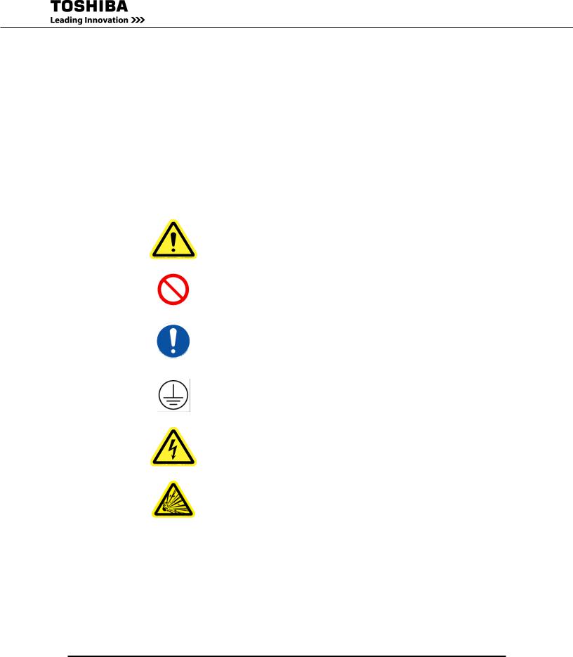
The symbols listed below are used throughout this manual. When symbols are used in this manual they will include important safety information that must be carefully followed.
Safety Alert Symbol indicates that a potential personal injury hazard exists.
Prohibited Symbol indicates DO NOT take action.
Mandatory Symbol indicates that the following instruction is required.
Ground Symbol indicates the location of the equipment grounding conductor.
Electrical - Voltage & Shock Hazard Symbol indicates parts inside may cause electric shock.
Explosion Hazard Symbol indicates parts may explode.
2 |
G8000 Series Installation and Operation Manual |
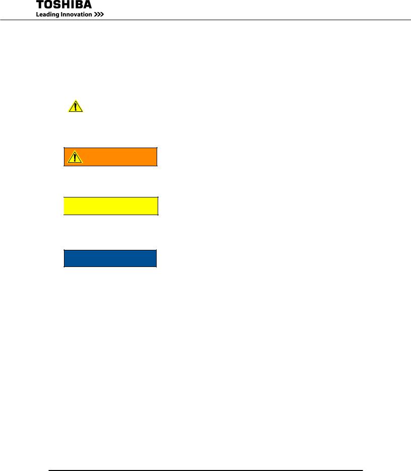
2.2Signal Words
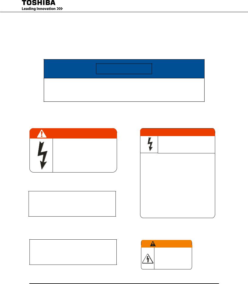
The signal words listed below are used throughout this manual. When the words DANGER, WARNING, CAUTION and ATTENTION are used in this manual they will include important safety information that must be carefully followed.
|
|
|
The word DANGER in capital letters preceded by |
|
|
|
|
|
DANGER |
|
|
|
|
the safety alert symbol indicates that an imminently |
|
|
|
|
hazardous situation exists, and if not avoided |
|
|
|
|
|
|
|
will result in loss of life or serious injury to |
|
|
|
personnel. |
The word WARNING in capital letters preceded by WARNING the safety alert symbol indicates that a potentially hazardous situation exists, and if not avoided
may result in loss of life or serious injury to personnel.

 CAUTION
NOTICE
2.3Qualified Personnel
The word CAUTION in capital letters preceded by the safety alert symbol indicates that a potentially hazardous situation exists, and if not avoided may result in minor or moderate injury.
The word NOTICE in capital letters without the safety alert symbol indicates a potentially hazardous situation exists, and if not avoided may result in equipment and property damage.
Installation, operation, and maintenance shall be performed by Qualified Personnel Only. A Qualified
Person is one that has the skills and knowledge relating to the construction, installation, operation, and maintenance of the electrical equipment and has received safety training on the hazards involved (Refer to the latest edition of NFPA 70E for additional safety requirements).
Qualified Personnel shall:
•Have read the entire operation manual.
•Be familiar with the construction and function of the UPS, the equipment being driven, and the hazards involved.
•Be trained and authorized to safely energize, de-energize, ground, lockout/tagout circuits and equipment, and clear faults in accordance with established safety practices.
•Be trained in the proper care and use of protective equipment such as safety shoes, rubber gloves, hard hats, safety glasses, face shields, flash clothing, etc., in accordance with established safety practices.
G8000 Series Installation and Operation Manual |
3 |
•Be trained in rendering first aid.
For further information on workplace safety visit www.osha.gov.
2.4Factory Authorized Personnel
Factory authorized personnel have been factory trained and certified to install, service, and repair the
UPS. Contact the Toshiba Customer Support Center for assistance in locating the factory authorized personnel nearest you.
3 Important Safety Instructions
The following contains important instructions that should be followed during the installation, operation, and maintenance of the G8000 Series UPS.
Please refer to the battery manufacturer’s instructions for details on operating, maintaining and/or replacing the batteries for each system. Keep unauthorized personnel from batteries. Only a certified service representative with battery experience should perform service on batteries.

 CAUTION
Misuse of this equipment could result in personal injury and/or equipment damage. In no event will Toshiba Corporation be responsible or liable for either indirect or consequential damage or injury that may come from the use of this equipment.
The UPS system input and output is NOT equipped with an over-current protection device, or an output disconnection at the AC output. The user should provide circuit breakers between the UPS AC input (or Bypass input) and the power sources and between the UPS output and the critical load input. The minimum device ratings are listed in Table 3.1.
TABLE 3.1 UPS MINIMUM DEVICE RATINGS
Capacity |
Rated Output |
Input Breaker Rating |
Output Breaker Rating |
|
|
|
|
80 kVA |
480 V/277 V |
480 V – 150 A |
480 V – 125 A |
100 kVA |
480 V/277 V |
480 V – 200 A |
480 V – 150 A |
125 kVA |
480 V/277 V |
480 V – 200 A |
480 V – 200 A |
150 kVA |
480 V/277 V |
480 V – 300 A |
480 V – 250 A |
225 kVA |
480 V/277 V |
480 V – 400 A |
480 V – 350 A |
300 kVA |
480 V/277 V |
480 V – 600 A |
480 V – 500 A |
500 kVA |
480 V/277 V |
480 V – 800 A |
480 V – 800 A |
80/100/150/225/300 kVA Temperature restrictions: The maximum operating ambient temperature is 86 °F (30 °C) at 1.0 PF, and 104 °F (40 °C) at 0.8 PF. If the UPS is exposed to the same ambient temperature as the battery system, the maximum operating ambient temperature is 86 °F (30 °C) at 1.0 PF, 90 °F (32 °C) at 0.8 PF. Table 3.2 lists the nominal battery voltage.
4 |
G8000 Series Installation and Operation Manual |

TABLE 3.2 UPS NOMINAL BATTERY VOLTAGE
Capacity |
Nominal Voltage |
Float Voltage |
80 kVA |
360 Vdc |
405 V |
100 kVA |
360 Vdc |
405 V |
125 kVA |
360 Vdc |
405 V |
150 kVA |
360 Vdc |
405 V |
225 kVA |
360 Vdc |
405 V |
300 kVA |
360 Vdc |
405 V |
500 kVA |
480 Vdc |
540 V |
4 Safety Precautions
The Toshiba products listed in this document are intended for usage in general electronics applications
(computer, personal equipment, office equipment, measuring equipment, industrial robotics, domestic appliances, etc.). These Toshiba products are neither intended nor warranted for use in equipment that, if a malfunction or failure occurs, may result in loss of human life or bodily injury (collectively referred to as “Unintended Usage”). Unintended Usage includes atomic energy control instruments, airplane or spaceship instruments, transportation instruments, traffic signal instruments, combustion control instruments, medical operating room or life support equipment, all types of safety devices, etc. Unintended Usage of Toshiba products listed in this document shall be made at the customer’s own risk.
The application of the UPS without special consideration for equipment that supports human safety and/or maintain public services may cause serious accidents.
4.1Disclaimer
IN NO EVENT WILL TOSHIBA CORPORATION BE RESPONSIBLE OR LIABLE FOR EITHER INDIRECT OR CONSEQUENTIAL DAMAGE OR INJURY THAT MAY COME FROM THE MISUSE OF THIS EQUIPMENT. ANY MODIFICATIONS WITHOUT AUTHORIZATION BY TOSHIBA COULD RESULT IN PERSONAL INJURIES, DEATH OR DESTRUCTION OF THE UPS.
TOSHIBA RESERVES THE RIGHT TO MAKE CHANGES WITHOUT FURTHER NOTICE TO ANY PRODUCTS HEREIN TO IMPROVE RELIABILITY, FUNCTION OR DESIGN. TOSHIBA DOES NOT ASSUME ANY LIABILITY ARISING OUT OF THE APPLICATION OR USE OF ANY PRODUCT OR UPS DESCRIBED HEREIN; NEITHER DOES IT CONVEY ANY LICENSE UNDER ITS PATENT RIGHTS, NOR THE RIGHTS OF OTHERS.
G8000 Series Installation and Operation Manual |
5 |
4.2General Maintenance

 WARNING
DO NOT remove the rear/side panels, or any sheet metla not designed to be removed.
Removing rear/side panels may result in electric shock, burns, personal injuries or UPS failure.
Keep the area arround the UPS clean.
Use a vacuum cleaner to clean the UPS.
Only factory authorized personnel sould perform internal general maintenance on the UPS.
Contact the authorized Toshiba Customer Support Center or an authorized Toshiba representative for informaton on proper disposal of UPS components.
It is illegal to dispose of certain components without conforming to environmental regulations for indusrial/commercial waste.
4.3Transporting/Unpacking

 WARNING
WhentransportingtheUPSbycrane,followtheSPECIFIEDWORKPROCEDURE. The suspension wire angle should be less than 60°.
The UPS falling or overturning may cause crushing, trapping or other personal injuries.
See Installation Manual: Chapter 8 - Transporting
DO NOT tilt the UPS more than 10° from upright position.
Tilting the UPS more than 10° may cause crushing, trapping or other personal injuries.
6 |
G8000 Series Installation and Operation Manual |
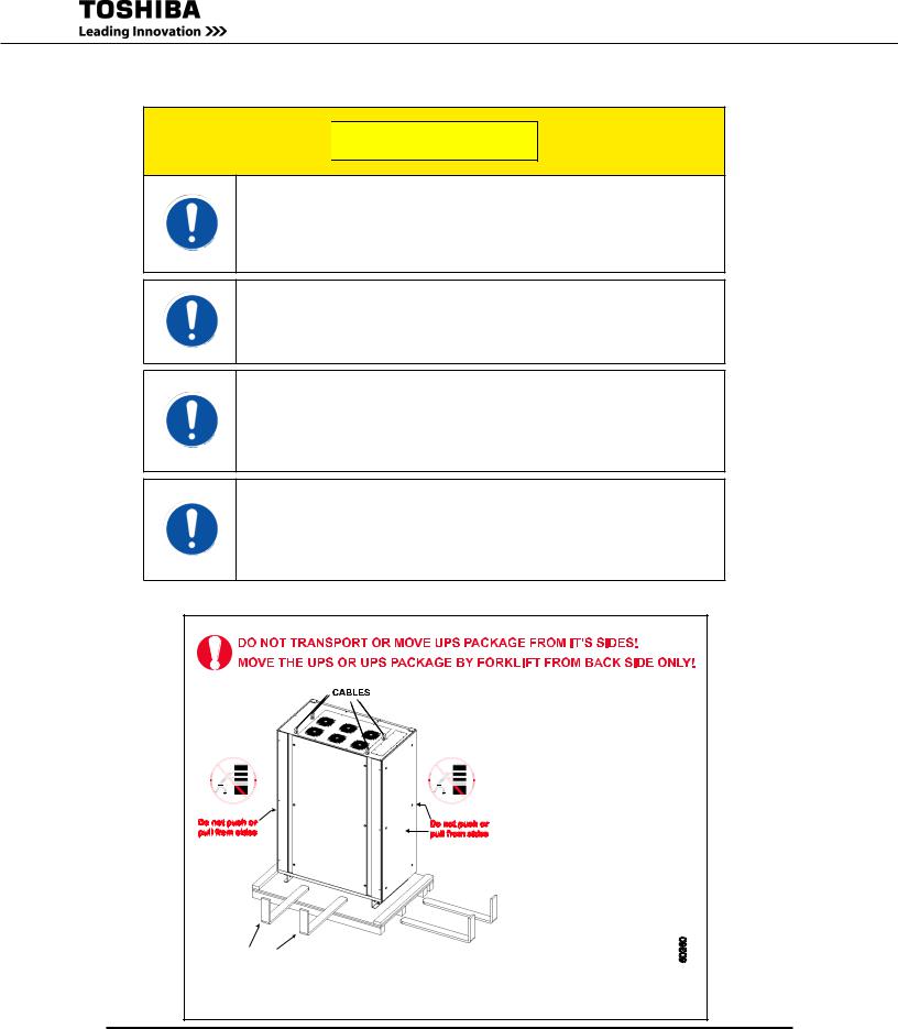

 CAUTION
DO NOT transport, move, store, or place the UPS on its side.
Forces due to heavy components inside may damage the UPS.
Avoid vibration or shock exceeding 0.5G.
Failing to observe this precaution may cause damage to the UPS.
DO NOT allow the UPS to suffer shock or impact when unpacking.
Tools used to remove packaging materials may cause damage to the UPS.
DO NOT push or pull on the sides of the packaging.or the UPS to move it. Always use a crane, forklift, or pallet jack for transporting and positioning the UPS.
Pushing/pulling on the sides of the unit to move it may result in damage to the UPS. See Figure 4.1 Exterior Handling label.
Fig. 4.1 Exterior Handling label
Do not push or pull from sides 
BACKSIDE
BY CRANE: -Cables should have sufficient rating and equal length. -Keep UPS leveled when lifting/lowering and avoid impacts.
BY FORKLIFT:
-Verify forklift maximum load capacity.
Do not push or -Ensure that the forks are long enough pull from sides to support the UPS and are inserted
properly. -Do not swing or tilt the UPS when lifting and/or transporting.
See manual for complete details.
FORKS (4 Ft. Minimum length)
WARNING:
Risk of tipping. For safe handling, lift UPS from back and sides only (as shown above)
G8000 Series Installation and Operation Manual |
7 |

4.4Inspection/Storage
Inspection
Upon receipt of the UPS, an inspection for shipping damage should be performed. Use caution when removing the unit from the pallet. Refer to labels or documentation attached to packing material.
Unpacking
Check the unit for loose, broken, bent or otherwise damaged parts. If damage has occurred during shipping, keep all original crating and packing materials for return to the shipping agent.
NOTE: The factory warranty does not apply to damage incurred during shipping!
Ensure that the rated capacity and the model number specified on the nameplate conform to the order specifications.
Storage
During periods of non-use, the following guidelines are recommended for storage.
Storage Preparation
1)Power up the UPS and allow it to operate with no load for 24 hours to fully charge the batteries.
2)Stop the unit.
3)Place the Main Circuit Breaker switch in the “OFF” position.
Storage Conditions
•For best results, store the UPS in the original shipping container and place on a wood or metal pallet
•Storage temperature range: -4 to 104 °F (-20 to 40 °C)
•The optimum storage temperature is 70 °F (21 °C). Ahigher ambient temperature will require recharging more frequently during storage
Avoid the following storage locations:
•Locations that are subject to extreme temperature changes or high humidity
•Locations that are subject to high levels of dust or metal particles
•Locations that are subject to excessive vibration
•Inclined floor surfaces
8 |
G8000 Series Installation and Operation Manual |
5 Installation Precautions

 CAUTION
Install the UPS in a controlled environment.
Improper storage and installation environment may deteriorate insulation, shorten component life and cause malfunctions.
See Table 5.1 - UPS Installation Environment Standards
DO NOT tilt the UPS more than 10° from upright position.
Tilting the UPS more than 10° may cause crushing, trapping or other personal injuries and cause physical damage to internal components.

 WARNING
Keep the SPECIFIED CLEARANCE around the UPS.
Inadequate space around the UPS makes it difficult to perform maintenance/inspections, will lead to insufficient ventilation, and/or cause malfunctions.
Install anchor bolts to secure the UPS to the installation floor.
The UPS may fall during an earthquake if the anchor bolts are not installed and secured.
Only factory authorized personnel should relocate, modify, or replace parts in the UPS after initial installation.
Electrical shock, injury or UPS failure may occur if non-authorized technicians attempt to modify or relocate the UPS.
Please contact Toshiba Customer Support Center if you plan to move or make modifications to the UPS
G8000 Series Installation and Operation Manual |
9 |
DO NOT block air vents.
Blocking the vents will increase the internal temperatures and may result in UPS failure or fire.
DO NOT install the UPS where water may fall on it.
Water may cause electrical shock, personal injury or UPS failure.
DO NOT use floor wax that contains silicon in the UPS storage area and/or nearby rooms.
Floor wax that contains silicon may cause static electricity.

 WARNING
The UPS should be installed per local and/or national electric codes by qualified personnel.
Faults or improper operation may occur if the UPS is not installed properly.
When an external maintenance bypass is installed for the UPS, before switching to external bypass, ensure that the UPS unit is switched to AC Bypass mode and the UPS control panel display verifies the unit is Bypass mode.
Switching to the external bypass while the unit is in UPS mode may damage the UPS.
10 |
G8000 Series Installation and Operation Manual |
TABLE 5.1 - UPS INSTALLATION ENVIRONMENT STANDARDS
Item |
Environment standard |
|
Installation Location |
Indoors |
|
|
Minimum operating temperature: 32 °F (0 °C). |
|
|
Maximum operating temperature: 86 °F (30 °C) at 1.0 PF (UPS with/without |
|
|
battery system). |
|
Ambient |
Maximum operating temperature: 90 °F (32 °C) at 0.8 PF (UPS with battery |
|
Temperature |
system). |
|
|
Maximum operating temperature: 104 °F (40 °C) at 0.8 PF (UPS only). |
|
|
Average 24-hour operating temperature: 86 °F (30 °C) at 1.0 PF and 41 – 95 °F |
|
|
(5 – 35 °C) at 0.8 PF. |
|
Relative Humidity |
The relative humidity must be between 30 and 90% noncondensing due to |
|
temperature changes. |
|
|
|
|
|
|
These specifications are for altitudes up to 3240 ft. (1000 m) above sea level. |
|
Altitude |
Consult with the factory to determine the derating factor for installations above |
|
|
3240 ft. (1000 m). |
|
|
Installation environment must not have vibration frequencies 10 Hz – 20 Hz. |
|
Vibration and |
The acceleration due to vibrations less than 10 Hz must not exceed 0.5 G. |
|
Mechanical Shock |
The acceleration due to vibrations 20 Hz – 50 Hz must not exceed 0.5 G. |
|
|
The total amplitude due to vibrations 50 Hz – 100 Hz must not exceed 0.1 mm. |
|
Dust |
Dust must not exceed normal atmospheric levels and must not include conductive |
|
particles, silicone or oils. |
|
|
|
|
|
|
No flammable and/or explosive gas. |
|
|
Hydrogen sulfide (H2S) |
Less than or equal to 0.0001 PPM |
|
|
|
|
Sulfurous acid gas (SO2) |
Less than or equal to 0.05 PPM |
|
|
|
|
Chlorine gas (Cl2) |
Less than or equal to 0.002 PPM |
Flammable Gas |
|
|
Ammonia gas (NH3) |
Less than or equal to 0.1 PPM |
|
|
Nitrous acid gas (NO2) |
Less than or equal to 0.02 PPM |
|
|
|
|
Nitrous oxides (NOx) |
Less than or equal to 0.02 PPM |
|
Ozone (O3) |
Less than or equal to 0.002 PPM |
|
Hydrochloric acid mist (HCl) |
Less than or equal to 0.1 mg/m3 |
Installation Precautions
1)Install the unit in a stable, level and upright position that is free of excessive vibration.
2)Install the unit where the ambient temperature is within the specified range.
3)DO NOT install the UPS in areas that are subject to high humidity.
4)DO NOT install the UPS in areas that allow exposure to direct sunlight.
5)DO NOT install the UPS in areas that allow exposure to high levels of airborne dust, metal particles, or flammable gases.
6)DO NOT install the UPS in areas near sources of electrical noise. Ensuring a proper earth ground will reduce the effects of electrical noise and will reduce the potential for electrical shock.
G8000 Series Installation and Operation Manual |
11 |
7)The UPS generates and can radiate radio-frequency energy during operation. Although
RFI noise filters are installed inside of the unit, there is no guarantee that the UPS will not influence some sensitive devices that are operating near by. If such interference is experienced, the UPS should be installed further away from the affected equipment and/or powered from a different source than that of the installed equipment.
8)The user should provide over-current protection for hardwired UPS systems between the UPS output and the load input.
9)After ensuring that all power sources are turned “OFF” and isolated in accordance with established lockout/tagout procedures, connect the power source wiring of the correct voltage to the input terminals of the UPS.
NOTE: Ensure the input phasing is connected in clockwise rotation (CW). UPS internal circuitry is designed to disable further UPS operation if the input phasing is installed in counter-clockwise rotation (CCW).
10)Connect the output terminals of the UPS to the load (refer to NEC Article 300 - Wiring Methods and Article 310 - Conductors For General Wiring). Size the branch circuit conductors in accordance with NEC Table 310.16 as published 9/2007.

 WARNING
METAL CONDUIT IS NOT AN ACCEPTABLE GROUND.
Conductor Routing and Grounding
1)Use separate metal conduits for routing the input power, output power, and control circuits.
2)Follow the wire size and tightening torque specifications.
3)Always ground the unit to reduce the potential for electrical shock and to help reduce electrical noise.
4)A separate ground cable should be run inside the conduit with the input power, output power, and control circuits.
12 |
G8000 Series Installation and Operation Manual |
5.1Wiring/Connection

 WARNING
Perform wiring and connections with correct polarity.
Be careful when connecting the UPS to the battery system. A wrong connection may cause damage to the UPS, battery, or charger.
Connect ONLY one (1) ground wire to the earth ground terminal.
A missing ground wire may cause an electrical shock hazard.
Connecting to more than one ground may cause a ground loop.
See Chapter 8 - UPS Wiring
DO NOT force, bend, or pull wires. DO NOT damage wire insulation.
DO NOT place heavy objects on top of UPS.
Observe the above precautions when making wire connections or handling the wires. Failing to observe these precautions may damage the insulation of the wires or may cause a fire or an electric shock hazard.
NOTICE
Follow the torque criteria for tightening screws.
Loose connections may cause fire due to heating.
See Chapter 11 - UPS Wiring
G8000 Series Installation and Operation Manual |
13 |
6 Warning Labels
Below are representative warning labels and their location on the UPS. Exterior Handling labels shown in section 4.3, Transporting/Unpacking, are in the manual packet, and attached to the UPS shipping covering and shipping pallet.
NOTICE
Make sure all the warning labels are installed in the appropriate locations.
If a label is missing or illegible, contact Toshiba Customer Support Center or an authorized representative.
(A) 48082
DANGER
AC VOLTAGE
This UPS receives power from more than one source. Disconnect all AC sources before performing any service or testing inside this unit
48082
(C) 56875FOR80,100,100,150,150,225KVAKVA
USE COPPER CONDUCTORS ONLY!
REFER TO INSTRUCTION MANUAL FOR WIRE SIZE AND TIGHTENING TORQUE
1 |
2 |
|
3 |
|
4 |
5 |
|
6 |
7 |
|
8 |
9 |
|
10 |
11 |
|
12 |
|
13 |
|||||
|
|
|
|
|
|
|
|
|
|
|
|
|
|
|
|
|
|
|
|
|
|
|
|
|
U |
V |
|
W |
U |
V |
|
W |
N |
|
U |
V |
|
W |
N |
- |
|
+ |
|||||||
|
|
|
|
|
|
|
|
|
|
|
|
|
|
|
|
|
|
|
|
|
|
|
|
|
|
|
|
|
|
|
|
|
|
|
|
|
|
|
|
|
|
|
|
|
|
|
|
|
|
|
|
480V |
|
|
|
|
|
480V |
|
|
|
|
|
480V |
|
|
|
|
400V |
|||||
|
|
AC INPUT |
|
|
|
|
BYPASS INPUT |
|
|
|
|
AC OUTPUT |
|
|
|
BATTERY |
||||||||
(C) 58708 FOR 300KVA
USE COPPER CONDUCTORS ONLY !
REFER TO INSTRUCTION MANUAL FOR WIRE SIZE AND TIGHTENING TORQUE
|
1 |
2 |
|
3 |
|
4 |
|
5 |
|
6 |
|
7 |
|
8 |
|
9 |
|
10 |
|
11 |
12 |
|||
|
|
|
|
|
|
|
|
|
|
|
|
|
|
|
|
|
|
|
|
|
|
|
|
|
|
U |
V |
|
W |
- |
|
+ |
U |
V |
|
W |
|
N |
U |
|
V |
|
W |
||||||
|
|
|
|
|
|
|
|
|
|
|
|
|
|
|
|
|
|
|
|
|
|
|
|
|
|
|
|
|
|
|
|
|
|
|
|
|
|
|
|
|
|
|
|
|
|
|
|
|
|
58708 |
|
|
480V |
|
|
|
|
400V |
|
|
|
480V |
|
|
|
480V |
|
|
||||||
|
|
AC INPUT |
|
|
|
BATTERY |
|
|
BYPASS INPUT |
|
|
AC OUTPUT |
|
|
||||||||||
(B) 40308
 DANGER
HAZARDOUS VOLTAGES
Hazardous voltages are used in the operation
of this equipment and could cause severe personal injury or loss of life.
The following precautions should be observed to reduce the risk of injury or death.
Only qualified technicians familiar with this equipment and the information supplied with it should be permitted to install and operate this equipment.
Installation of electrical equipment must be done in accordance with National Electrical Code and any other state or local codes. Proper grounding and conductor sizing must be installed for safe operation.
During operation, keep all covers in place and cabinet doors shut.
When performing visual inspections and maintenance, if possible, be sure the UPS is turned off and the incoming AC feed is turned off and locked out.
The UPS and Battery Cabinet will have hazardous voltages present even after the AC feed is turned off.
If it is necessary to make measurements with the power on, do not touch any electrical connection points. Remove
all jewelry from wrists and fingers. Make sure test equipment is in good, safe operating condition.
While servicing, stand on some type of insulation, and be sure not to be grounded.
Follow the safety instructions given in the equipment manual carefully and observe all danger, warning and caution notices.
40308
(D) 40830
WA RN I N G
CRITICAL FUSE SIZING
Incorrect fuse replacement size may result in fire or inadequate equipment protection.
Replace only with same type and rating of fuse.
14 |
G8000 Series Installation and Operation Manual |
(E) 39561
DANGER
RISK OF ELECTRIC SHOCK
Capacitors stay charged after power has been shut off.
Accidental contact with live parts can cause personal injury and death.
Turn off and lock out all power sources. Wait at least five (5) minutes for power to dissipate then check voltage before servicing. 39561
(F) 58705 SERIAL LABEL |
(G) 57055 |
||||||||
|
|
|
|
|
|
|
|
|
|
UNINTERRUPTIBLE POWER SUPPLY |
|
|
|
|
|
|
|
|
|
|
|
|
|
|
|
|
|
||
|
|
|
|
|
|
|
|
|
GND |
|
|
|
|
|
|
|
|
|
|
|
|
|
|
|
|
|
|
|
|
|
|
|
|
|
|
|
|
|
|
|
|
|
58705 |
|
MFD. IN U.S.A. FROM FOREIGN AND DOMESTIC COMP ONENTS |
|
LISTED |
|
|
® |
27E5 |
® |
|
|
HOUSTON,TEXAS |
|
|
|
|
(I) 40831
C A U TI ON
Heat sink not grounded. |
|
Risk of electrical shock. |
|
Disconnect UPS and electrically |
|
test heat sink before touching. |
PN 40831 |
|
(J) 57053
C A U TI ON
8A
(control power source switch)
Do not turn off while operating.
6.1Warning Label Locations
FIGURE 6.2 – 80/100/125 KVA UPS WARNING LABELS
G8000 Series Installation and Operation Manual |
15 |

FIGURE 6.3 – 150/225 KVA UPS WARNING LABELS
FIGURE 6.4 - 300 KVA UPS WARNING LABELS
16 |
G8000 Series Installation and Operation Manual |
FINAL LAYOUT NOT AVAILABLE AT THIS TIME: CONTACT THE FACTORY FOR ADDITIONAL INFORMATION
FIGURE 6.3 – 500 KVA UPS WARNING LABELS
G8000 Series Installation and Operation Manual |
17 |
7 Weight and Dimensions
Table 7.1 lists the unit and shipping weights for G8000 UPS models. See Appendix B for detailed outline and dimensioins of all models.
TABLE 7.1 G8000 UPS UNIT AND SHIPPING WEIGHTS
Model |
Unit |
Shipping |
80 kVA |
1390 lb. (630 kg) |
1440 lb. (652 kg) |
|
|
|
100 kVA |
1740 lb. (789 kg) |
1790 lb. (812 kg) |
|
|
|
125 kVA |
1740 lb. (789 kg) |
1790 lb. (812 kg) |
|
|
|
150 kVA |
2467 lb. (1119 kg) |
2556 lb. (1159 kg) |
225 kVA |
2980 lb. (1352 kg) |
3069 lb. (1392 kg) |
300 kVA |
4575 lb. (2075 kg) |
4725 lb. (2143 kg) |
500 kVA (Input Cabinet) |
1570 lb. (712 kg)1 |
~1620 lb. (735 kg)1 |
500 kVA (Output Cabinet) |
4950 lb. (2245 kg)1 |
~5100 lb. (2313 kg)1 |
1 - Weights are approximate.
18 |
G8000 Series Installation and Operation Manual |
8 Transporting

 WARNING
WhentransportingtheUPSbycrane,followtheSPECIFIEDWORKPROCEDURE. The suspension wire angle should be less than 60°.
The UPS falling or overturning may cause crushing, trapping or other personal injuries.
DO NOT tilt the UPS more than 10° from upright position.
Tilting the UPS more than 10° may cause crushing, trapping or other personal injuries.

 CAUTION
DO NOT transport, move, store, or place the UPS on its side.
Excessive force applied from heavy components inside may damage the UPS.
Avoid vibration or shock exceeding 0.5G.
Failing to observe this precaution may cause damage to the UPS.
DO NOT allow the UPS to suffer shock or impact when unpacking.
Tools used to remove packaging materials may cause damage to the UPS.
DO NOT install the UPS where water may fall on it.
Water may cause electrical shock, personal injury or UPS failure.
DO NOT push or pull on the sides of the packaging.or the UPS to move it. Always use a crane, forklift, or pallet jack for transporting and positioning the UPS.
Pushing/pulling on the sides of the unit to move it may result in damage to the UPS. (See Figure 4.1 Exterior Handling label.)
The UPS may be packed in a crate for extra protection during transportation. Avoid impact or vibration against the UPS during transportation. DO NOT expose the UPS directly to water.
G8000 Series Installation and Operation Manual |
19 |
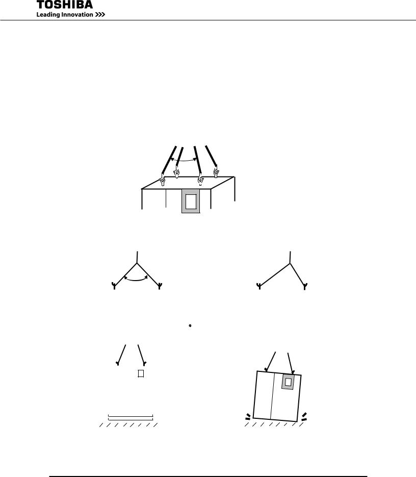
8.1Transporting By Crane
Cables should have sufficient ratings and be of the same length. Make sure the suspension cables are hooked at eyebolts. See Figure 8.1. Keep the angle less than 60° between cables.
Refer to Chapter 7 - Weight and Dimension for UPS cabinet weight.
Keep UPS leveled when lifting. DO NOT swing or tilt the UPS. Minimize the impact when lowering the UPS to the floor. Figure 8.2 and 8.3 indicate unacceptable lifting.
Figure 8.4 and 8.5 show examples of acceptable and unacceptable operations.
Less than 60°
FIGURE 8.1 - CABLES AND EYEBOLTS TO LIFT THE UPS
FIGURE 8.1 - CABLES AND EYEBOLTS TO LIFT THE UPS
|
|
|
More than 60° |
|
|
|
|
Uneven Cables |
|||||
|
|
|
|
|
|
|
|
|
|
|
|
|
|
|
|
|
|
|
|
|
|
|
|
|
|
|
|
|
|
|
|
|
|
|
|
|
|
|
|
|
|
|
|
|
|
|
|
|
|
|
|
|
|
|
|
|
FIGURE 8.2 - ANGLE MORE THAN 60° |
FIGURE 8.3 - UNEVEN CABLES |
||||||||||||
FIGURE 8.2 - ANGLE MORE THAN 60° |
FIGURE 8.3 - UNEVEN CABLES |
|||||||||||||
|
|
|
|
|
|
|
|
|
|
|
|
|
|
|
|
|
|
|
|
|
|
|
|
|
|
|
|
|
|
|
|
|
|
|
|
|
|
|
|
|
|
|
|
|
|
|
|
|
|
|
|
|
|
|
|
|
|
|
|
|
|
|
|
|
|
|
|
|
|
|
|
|
|
|
|
|
|
|
|
|
|
|
|
|
|
|
|
|
|
|
|
|
|
|
|
|
|
|
|
|
|
|
|
|
|
|
|
|
|
|
|
|
|
|
|
|
|
|
|
FIGURE 8.4 - ACCEPTABLE OPERATION |
FIGURE 8.5 - UNACCEPTABLE OPERATION |
20 |
G8000 Series Installation and Operation Manual |
Loading...