

Page 1

SST for MAGNIA™ 3310
User’s Guide
Server Setup TooL
Page 2

Copyright
This guide is copyrighted by TOSHIBA Corporation with all rights reserved.
Under the copyright laws, this guide cannot be reproduced in any form without
the prior written permission of TOSHIBA. No patent liability is assumed, however, with respect to the use of the information contained herein.
© 2003 by TOSHIBA CORPORATION. ALL RIGHTS RESERVED.
First Edition July 2003
Notice
No part of this document may be reproduced without the permission of
Information in this document is subject to change without notice.
If you have questions or find errors in this document, please contact our cus-
TOSHIBA has no responsibility for operation results in any situations.
For differences between the keyboard described in this document and your
Description in this document:
[Enter] = [Entr], [Entrée], [Intro]
[Ctrl] = [Control], [Strg]
[Esc] = [Echap]
[Ins] = [Insert], [Inser], [Einfg]
[Del] = [Delete], [Entf], [Suppr], [Supr]
[Break] = [Attn], [Untbr], [Inter]
TOSHIBA.
tomer service center.
keyboard, please refer to the following information.
Page 3

Trademarks
MAGNIA is a trademark of TOSHIBA Corporation.
Intel, Xeon and Pentium are either registered trademarks or trademarks of Intel
Corporation.
MS, Microsoft and its logos, MS-DOS, Windows, Windows NT, Windows
Server and Active Directory are either registered trademarks or trademarks of
Microsoft Corporation in the United States and/or in other countries.
Ethernet is a registered trademark of Xerox Corporation.
Adaptec is a registered trademark of Adaptec, Inc.
MegaRAID and Power Console are registered trademarks of LSI Logic
Corporation.
Other product names and trademarks belong to the individual companies
concerned.
The mark "™" and "®" are not always written.
iii
Page 4

Contents
Chapter 1: Server Setup TooL ..................................................................... 2
Checking the Accessories ......................................................................... 3
Starting SST ................................................................................................ 3
Starting the server .................................................................................. 4
Starting SST on another system ......................................................... 6
Main Menu ................................................................................................... 7
Chapter 2: Setup .......................................................................................... 10
Setup Wizard ............................................................................................. 11
Operating System Installation Selection .......................................... 14
Windows Server 2003 Quick Installation .............................................. 16
Windows 2000 Quick Installation .......................................................... 38
Windows Server 2003 Manual Installation using SST ....................... 65
Windows 2000 Manual Installation using SST .................................... 66
Windows Server 2003/Windows 2000 Manual Installation without using
SST ............................................................................................................ 67
After Installation (Windows Server 2003) ............................................. 69
After Installation (Windows 2000) .......................................................... 71
Chapter 3: Utilities ........................................................................................ 74
How to Start Utilities ................................................................................. 75
About Utilities ....................................................................................... 75
Starting the Utilities program from SST CD-ROM .......................... 75
Selectable items when the Utilities program is started from SST CD-ROM 76
Starting the Utilities on another system ............................................ 77
Utility Menu ............................................................................................... 79
Page 5

vi
Setup Support ..................................................................................... 79
HW Setup ............................................................................................ 82
Chapter 4: Hardware Diagnostics ............................................................. 84
About Hardware Diagnostics ................................................................. 85
Starting the Hardware Diagnostics Program ....................................... 85
Items of Hardware Diagnostics .............................................................. 86
Diagnostics Test (01. DIAGNOSTIC TEST) ................................... 87
Running Test (02.RUNNING TEST) ................................................ 88
Log Utilities (03. LOG UTILITIES) .................................................. 105
System Configuration Display (04. SYSTEM CONFIGURATION) 108
Chapter 5: Application ............................................................................... 112
Installing HarnessEye/web ................................................................... 112
Installing the TOSHIBA Display Power Save Driver ......................... 114
Chapter 6: Troubleshooting ...................................................................... 116
Troubleshooting Information ................................................................. 116
Errors occuring during RAID creation ............................................ 117
Errors occuring during the OS installation ..................................... 123
Errors occuring during reading from a FD ..................................... 126
Errors occuring during starting SST ............................................... 126
Errors occuring by incorrect operation ........................................... 128
Page 6

Chapter 1
Checking the Accessories ............................................................ 3
Starting SST .................................................................................. 3
Main Menu .................................................................................... 7
Page 7

Server Setup TooL
This chapter describes how to configure the hardware and start the
Server Setup TooL.
2
Page 8
Checking the Accessories
Checking the Accessories
Before starting the Server Setup TooL (SST), make sure that the
following accessories are available.
SST CD-ROM (this CD)
Server Setup TooL User's Guide (This guide)
End-User License Agreement
Starting SST
NOTE: Depending on the optional equipment [i.e. SCSI card,
MO drive] you installed on the server, SST may work
incorrectly. To have the SST work correctly, do not install the
optional equipment [i.e. SCSI card, MO drive] on your server.
Server Setup TooL
3
NOTE: Do not turn off or reset the server while SST is working.
NOTE: Do not remove the SST CD-ROM while SST is working.
NOTE: The SST cannot be used to install the OS when hard
disk drives are connected to two or more disk controllers. To
install the OS using SST, one or more hard disk drives must
be connected to one disk controller.
NOTE: To use [Utilities]-[Create Floppy Disks] or
Configuration Save Disk, the floppy disk drive must be
connected.
Page 9
Server Setup TooL
4
Starting SST
Starting the server
1 Make sure that the monitor, keyboard, mouse and all peripher-
als are correctly connected.
NOTE: To start up SST from CD-ROM, the CD-ROM drive
must be set to have top priority in the Boot menu of the BIOS
setup utility. For details on how to set the Boot menu, refer to
the MAGNIA3310 User’ s Guide.
2 Make certain that all power cables are connected to grounded
AC outlets.
3 Turn on the power of the monitor.
Power Button
MAGNIA3310 Front View
4 Turn on the Power button on the computer front, and
immediately insert the SST CD-ROM into the CD-ROM
drive.
Page 10
Server Setup TooL
Starting SST
5 After a while, the Toshiba Server Setup TooL Start-up screen is
replaced with the Main menu.
Server Setup TooL Start-up screen
6 After the Server Setup TooL Start-up screen, the Input Locale
screen appears.
5
Input Locale screen
Select one of the following keyboard layouts.
Belgian French
French
German
Spanish
Swiss French
Swiss German
United Kingdom
U.S.
Page 11
Server Setup TooL
6
Starting SST
NOTE: The OS installation can be executed without starting
up the Main menu by inserting the Configuration Save Disk
containing the configuration information into the floppy disk
drive, and starting up SST. For details on the setup method,
see section [Setup Option] in Chapter 2.
Starting SST on another system
The Server Setup TooL can be started on systems running one of
the operating systems listed below:
Windows Server 2003, Windows 2000, Windows NT, Windows
Me, Windows 98, Windows 95.
To start the Server Setup TooL from another system(s):
1 Place the SST CD-ROM into the CD-ROM drive.
2 After the Input Locale screen appears, select one keyboard lay-
out.
3 After finishing the locale setting, the SST Main menu appears.
NOTE: The Input Locale screen always appears when you
start SST on another system.
NOTE: To use all the functions on the Utility menu, a floppy
disk drive is required.
NOTE: When the Server Setup TooL has been started on
another system, you can use only the Utilities option in the
Main menu.
If the Auto-Run function is not allowed, the Server Setup TooL
can not be star ted on another system.
Page 12
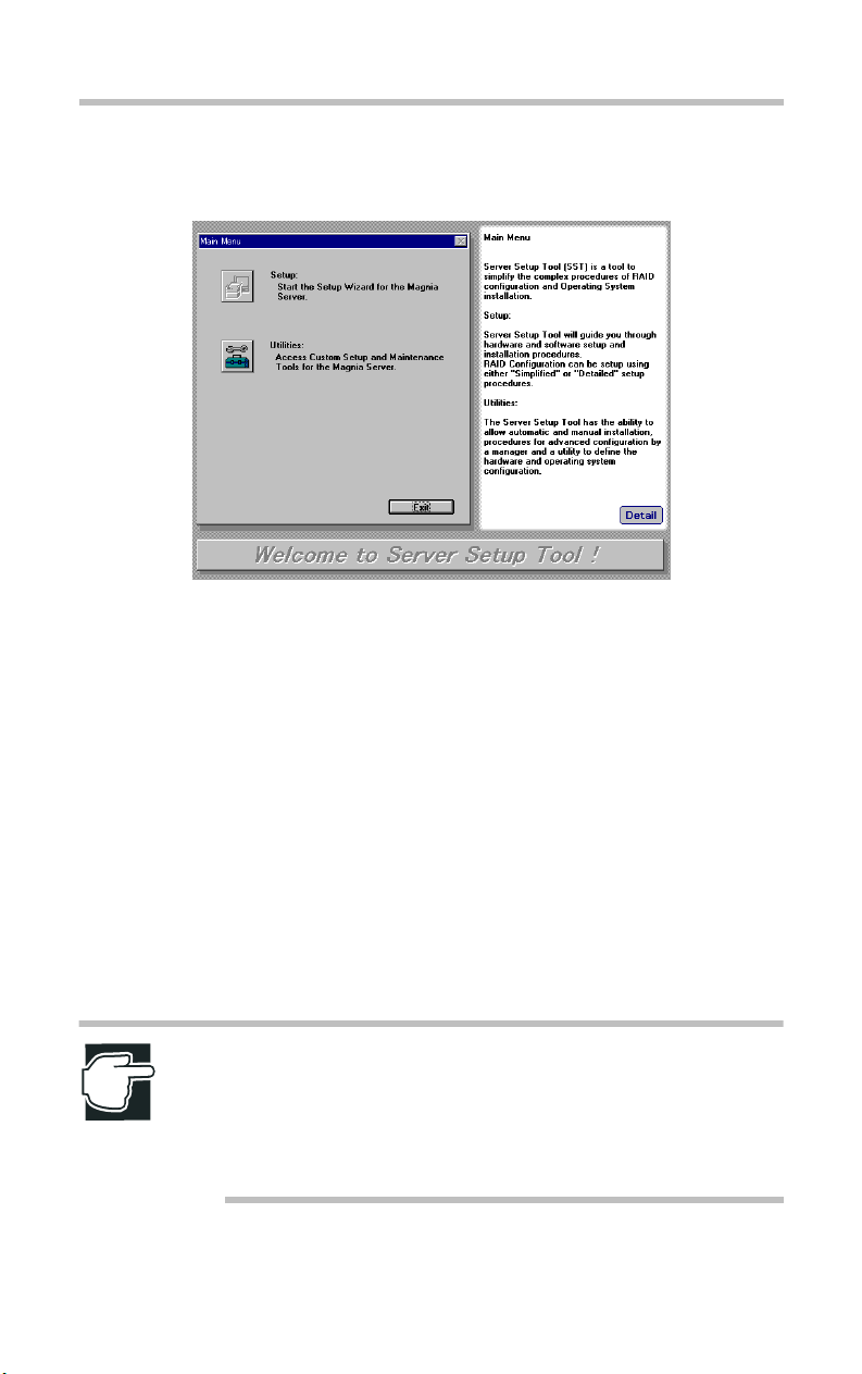
Main Menu
Main Menu screen
Setup
Server Setup TooL
Main Menu
7
The Setup option is designed to automate the installation of RAID
and the operating system. You are guided through a series of
questions, and then the system is automatically configured and the
software is installed. For more information, see section [Setup] in
Chapter 2.
Utilities
The Utilities option allows you to customize the system
installation, create diskettes, and manage the RAID configuration.
For more information, see section [Utilities] in Chapter3.
NOTE: When hard disk drives are connected to two or more
disk controllers, or when a hard disk drive does not exist, the
[Setup] option cannot be used. To use the [Setup] option, one
or more hard disk drives must be connected to one disk
controller.
Page 13

Chapter 2
Setup Wizard ............................................................................... 11
Windows Server 2003 Quick Installation ................................ 16
Windows 2000 Quick Installation ............................................ 38
Windows Server 2003 Manual Installation using SST .......... 65
Windows 2000 Manual Installation using SST ...................... 66
Windows Server 2003/Windows 2000 Manual Installation
without using SST ...................................................................... 67
After Installation (Windows Server 2003) .............................. 69
After Installation (Windows 2000) ........................................... 71
Page 14

Setup
This chapter describes how to use the Server Setup TooL.
10
Page 15
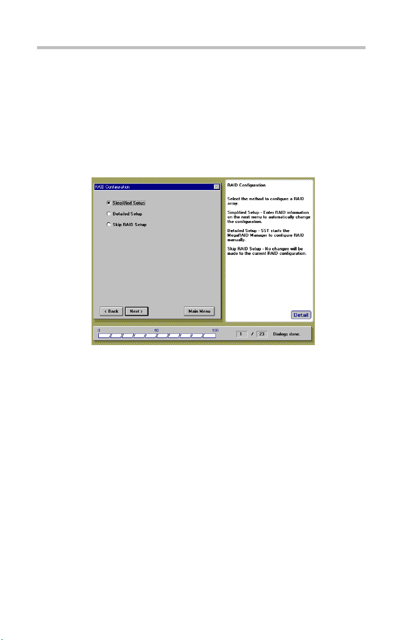
Setup Wizard
RAID Configuration
After selecting a Setup option from the SST Main menu, the
RAID Configuration screen appears only if one or more HDDs are
connected to the RAID controller (the MR518 or the MR520).
Setup
Setup Wizard
11
RAID Configuration screen
Simplified Setup
This option allows you to enter RAID type, Hot Spare option, and
other RAID configuration information.
Detailed Setup
This option manually starts the RAID configuration utility, and
then it allows you to manually configure the array.
(For more information, refer to the MegaRAID User's Manual.)
Skip RAID Setup
Skips setting up the RAID device.
Page 16
12
Setup
Setup Wizard
NOTE: If you are setting up the computer for the first time and
a RAID array has not yet been configured, use [Simplified
Setup] or [Detailed Setup].
NOTE: If you want to setup a RAID configuration that is not
possible by using [Simplified Setup], (for example: multiple
array groups, RAID10, RAID50, etc.), select [Detailed Setup].
For details about [Simplified Setup], click [Detail] and refer to
Server Setup TooL Help.
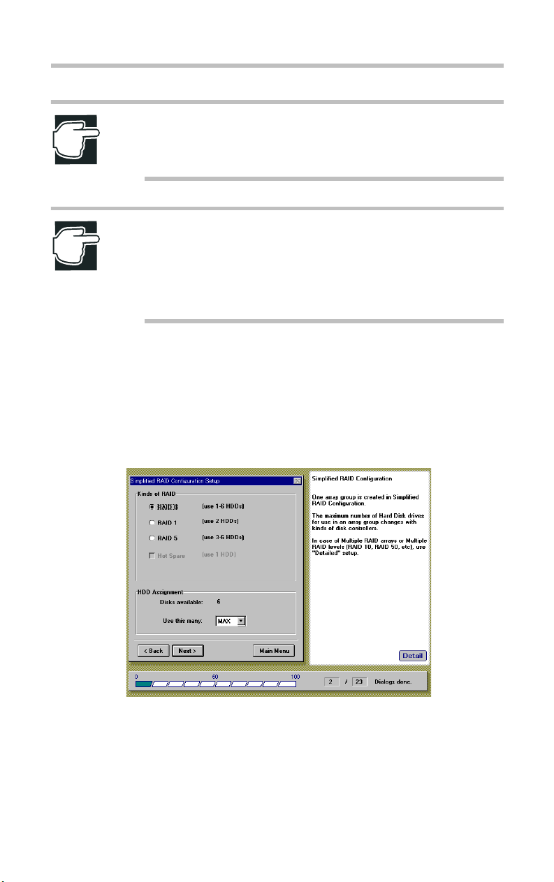
Simplified RAID Configuration Setup
If you have selected the Simplified Setup option on the RAID
Configuration screen, the Simplified RAID Configuration Setup
screen appears.
Simplified RAID Configuration Setup screen
RAID0 (One or more HDDs is required)
Multiple HDDs are grouped and constructed as one unique
logical device.
Page 17

Setup
Setup Wizard
Data is recorded in a dispersed manner and the write and read
performance of the HDDs is high.
RAID1 (Two HDDs are required)
The HDDs are mirrored images of each other. The same data is
always written to both HDDs. Therefore, if one HDD is damaged,
the operation can be continued by the other HDD.
RAID5 (Three or more HDDs are required)
Multiple HDDs are grouped and constructed as a single logical
device. Data and parity are recorded in the grouped HDDs in a
dispersed manner. If one HDD is damaged, the operation can be
continued by the other HDDs.
Hot Spare (Can be used if RAID1 or RAID5 is selected)
Hot Spare is a spare HDD in stand-by; when one HDD is
damaged, the hot spare automatically goes on-line.
HDD Assignment
13
Select the number of HDDs for the RAID configuration from the
list. When "MAX" has been selected, the RAID array is structured
with the maximum number of HDDs (= 6).
Page 18
Setup
14
Setup Wizard
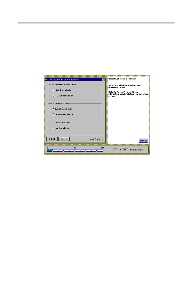
Operating System Installation Selection
After completing the RAID settings (or after selecting a Setup
option from the SST main menu, if you do not use a RAID
controller) the Operating System Installation Selection menu
appears.
Operating System Installation screen
Install Windows Server 2003
Quick Installation
Guides you through a quick installation of Windows Server 2003
Standard Edition or Windows Server 2003 Enterprise Edition
using the Server Setup TooL's automatic installation procedure.
Manual Installation
Allows you to perform a manual installation of Windows Server
2003 Standard Edition or Windows Server 2003 Enterprise
Edition. The necessary Diskettes for manual installation will be
automatically created.
Page 19
Setup
Setup Wizard
15
Install Windows 2000
Quick Installation
Guides you through a quick installation of Windows 2000 Server
or Windows 2000 Advanced Server using the Server Setup TooL's
automatic installation procedure.
Manual Installation
Allows you to perform a manual installation of Windows 2000
Server or Windows 2000 Advanced Server. The necessary
Diskettes for manual installation will be automatically created.
Install MS-DOS
Allows you to install MS-DOS.
No Installation
Skips the operating system installation process.
NOTE: If you want to install Windows Server 2003 or
Windows 2000 Server without using SST, create the
necessary diskettes for installation in the Utility menu first.
Refer to following.
[Chapter 2 - Windows Server 2003 Manual Installation
without using SST ] (Windows Server 2003)
[Chapter 2 - Windows 2000 Manual Installation without using
SST ] (Windows 2000)
The MAGNIA3310 User's Guide (on this Server Setup TooLand Documentation CD).
NOTE: If you selected [Install MS-DOS], the Server Setup
TooL will create a disk partition (from 50MB to 2,048MB).
Page 20
Setup
16
Windows Server 2003 Quick Installation
Windows Server 2003 Quick Installation
Locale Settings
NOTE: When you select the "Install Windows Server 2003 Quick installation" option, the following Locale Settings
screen appears.
Locale Settings screen
Select a Language for your Operating System.
NOTE: You must select the same OS language as your OS
CD-ROM. Once you have chosen a specific language [i.e.
French] for the SST installation of Windows Server 2003, do
not attempt to install a different language [i.e. Spanish]
version of Windows Server 2003 or the installation will fail.
Page 21
Setup
Windows Server 2003 Quick Installation
Create Disk Partition
After specifying the Locale Settings, the Create Disk Partition
screen appears.
Create Disk Partition screen
17
Select a file system.
FAT 16
Creates the file system using the FAT16 (File Allocation Table
with 16-bit entries) format.
NTFS
Creates the file system using the NTFS (NT File System) format.
Input Partition Size
Enter the size of the disk partition you want to create, then press
[Enter].
Page 22
18
Setup
Windows Server 2003 Quick Installation
NOTE: If you select "FAT16", SST will create a partition with a
size of 4096MB.
NOTE: If you select "NTFS" and enter a partition size larger
than available space on the disk, SST will create the partition
as 4096MB size default.
User Information Settings
After specifying the disk partition parameters, the User
Information Settings screen appears.
User Information Settings screen
Enter the following user settings:
User Name
Name of the user (administrator).
Organization
Company or organization name (optional).
Page 23
Setup
Windows Server 2003 Quick Installation
Product ID/CD Key
Product ID or CD-key of the Windows Server 2003 CD-ROM.
Computer Name
Identifies the computer to the rest of the network. The identifying
name should be 15 alphanumeric characters or less.
NOTE: To set up the Computer Name, you must use one or
more alphabetic characters.
19
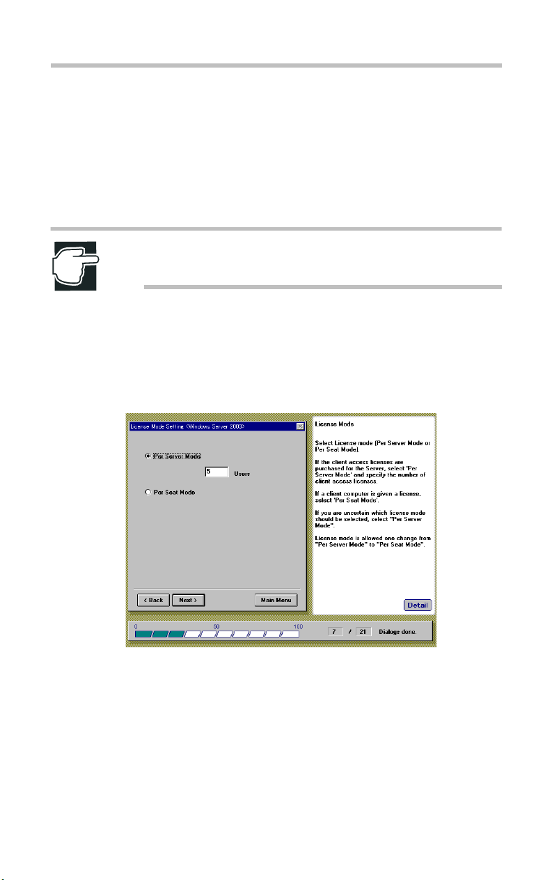
License Mode Setting
After specifying the User Information Settings, the License Mode
Setting screen appears.
License Mode Setting screen
You can structure the operating system license in one of two ways:
Per Server Mode
The server's license specifies the number of clients.
The number of users for a server should be no less than the
number of client computers that can simultaneously connect to
that server.
Page 24
20
Setup
Windows Server 2003 Quick Installation
Per Seat Mode
Each client computer (seat) has its own license, which allows it to
access any Windows Server 2003 on the network.
Select one of the two license modes and click [Next] after the
setting.
NOTE: If you are not sure which license mode to use, select
"Per Server Mode". The license mode can be changed once
only from "Per Server Mode" to "Per Seat Mode", based on
the contract for the license.
Server Role Setting
After specifying the License Mode Setting, the Server Role
Setting screen appears.
Server Role setting screen
Select one of the options, then click [Next].
Domain Member
Configures the computer as part of a domain, controlled by a
domain controller.
Page 25
Setup
Windows Server 2003 Quick Installation
Workgroup
User accounts and resources are controlled by the individual
computers.
NOTE: To make your server a domain controller, you must
install Active Directory after the Windows Server 2003
installation. See section [After Installation (Windows Server
2003)] in Chapter 2.
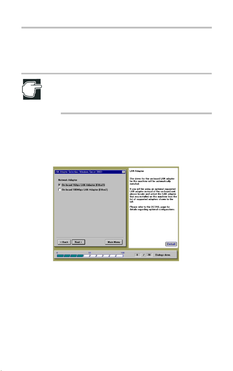
LAN Adapter Selection
After specifying the Server Role, the LAN Adapter Selection
screen appears.
21
LAN Adapter Selection screen
Select the LAN Adapter being used, then click [Next].
Onboard 1Gbps LAN Adapter (Ether1)
It is compatible with 1000BASE-T/100BASE -TX/10BASE-T
Ethernet LAN.
Onboard 100Mbps LAN Adapter (Ether2)
Page 26
22
Setup
Windows Server 2003 Quick Installation
It is compatible with 100BASE -TX/10 BASE-T Ethernet LAN.
NOTE: The [Onboard 1Gbps LAN Adapter (Ether1)] option is
always selected.
NOTE: The LAN driver for onboard LAN adapter (Ether2)
must be installed regardless of the setting of this screen. If the
[Onboard 100Mbps LAN Adapter (Ether2)] option is not
selected, onboard LAN adapter (Ether2) will be set up using
the default setting of Windows Server 2003.
Page 27
Setup
Windows Server 2003 Quick Installation
23
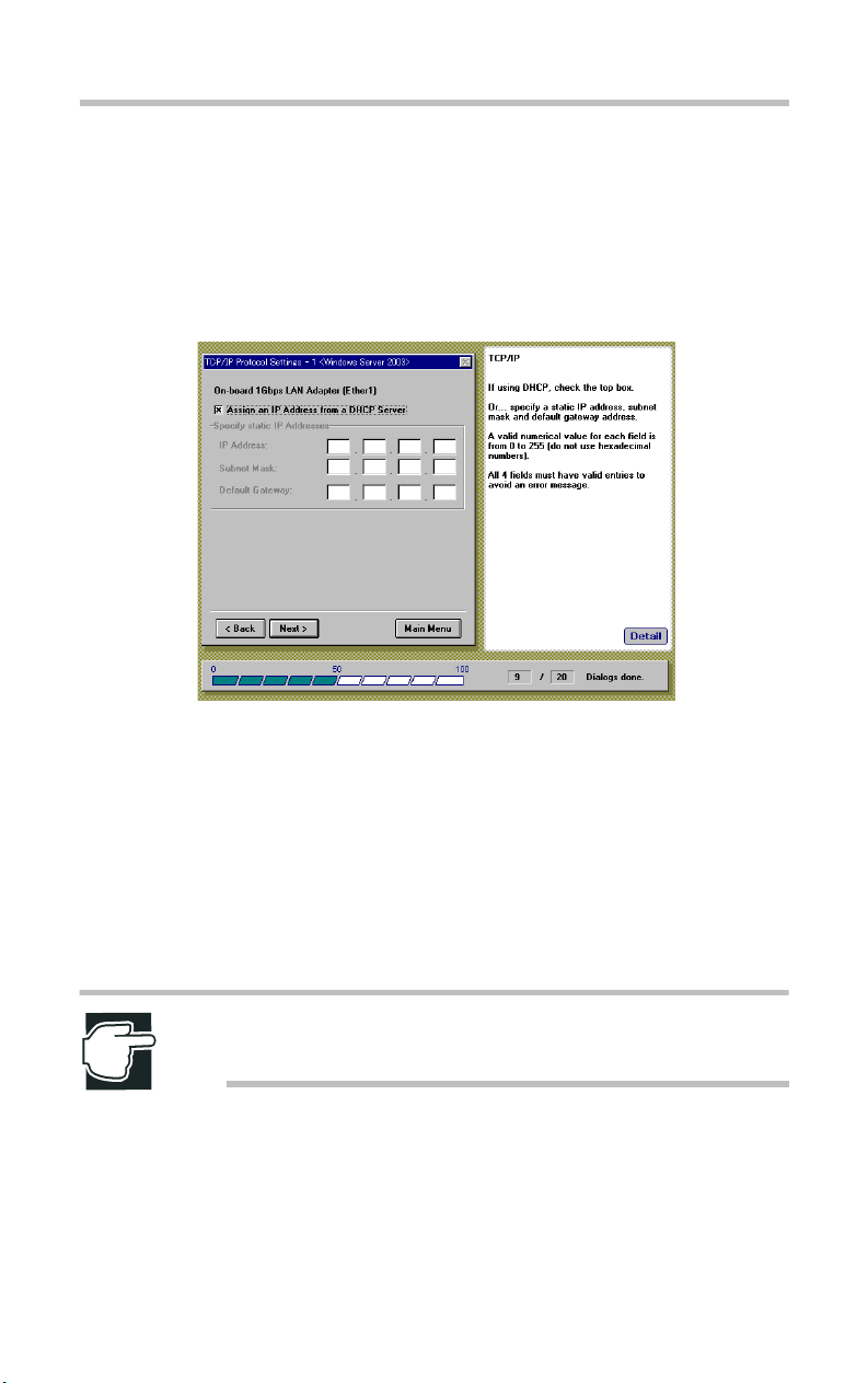
TCP/IP Protocol Settings -1
After specifying the LAN Adapter, the TCP/IP Protocol Settings 1 screen appears. The TCP/IP Protocol Settings -1 screen allows
you to specify the IP Address, Subnet Mask, and Default Gateway
Address for On-board 1Gbps LAN Adapter (Ether1).
TCP/IP Protocol Settings -1 screen
To have a DHCP server automatically assign the IP addresses,
Subnet Masks and Default Gateway for On-board 1Gbps LAN
Adapter (Ether1), select "Assign an IP Address from DHCP
Server".
Otherwise, do not select "Assign an IP Address from DHCP
Server" and specify manually the IP address, Subnet Mask, and
Default Gateway Address.
NOTE: For IP Address, Subnet Mask and Default Gateway
Address, you must use decimal numbers (from 0 to 255).
Page 28
24
Setup
Windows Server 2003 Quick Installation
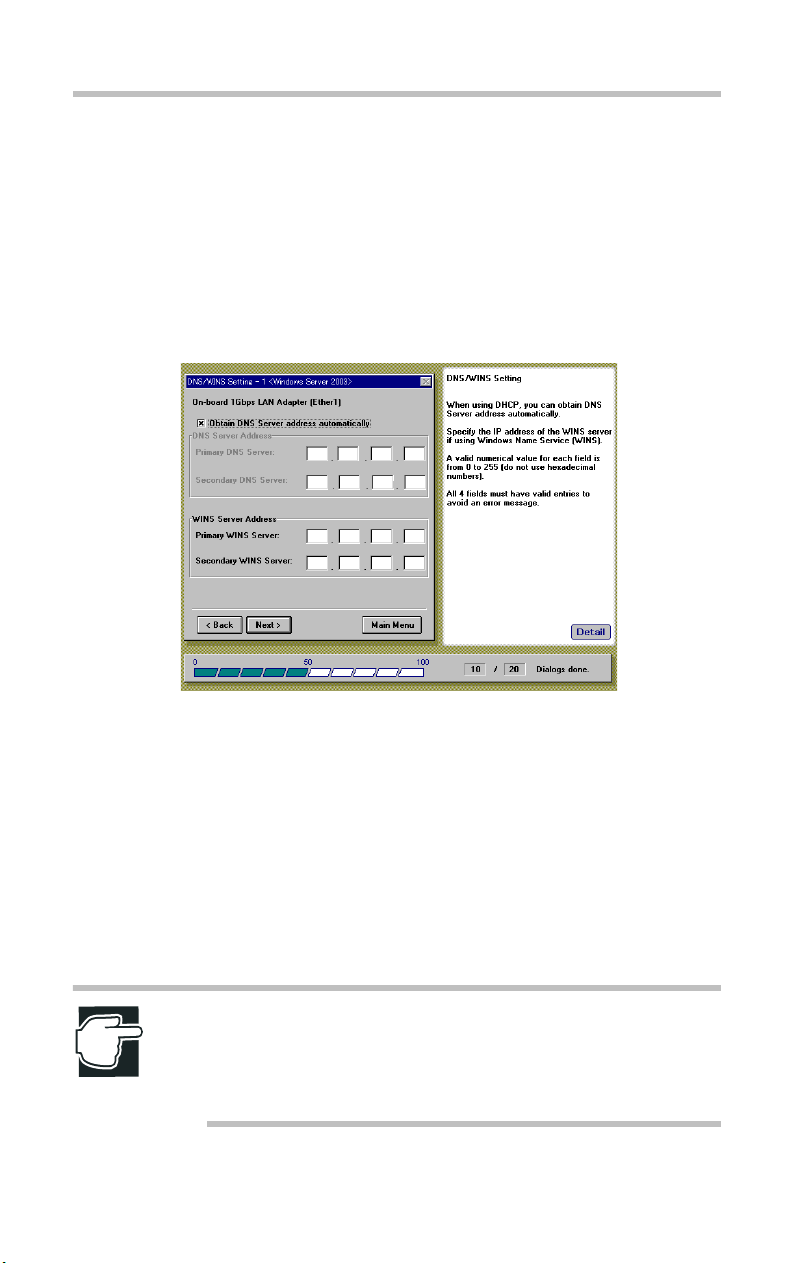
DNS/WINS Setting -1
After completing the settings on the TCP/IP Protocol Settings -1
screen, the DNS/WINS Setting -1 screen appears. This screen
allows you to specify the Primary DNS Server Address,
Secondary DNS Server Address, Primary WINS Server Address
and Secondary WINS Server Address for the On-board 1Gbps
LAN Adapter (Ether1).
DNS/WINS Setting -1 screen
If you plan to use the Domain Name System, you may specify the
IP addresses for you DNS servers in the fields "Primary DNS
Server" and "Secondary DNS Server". When using DHCP, you
can obtain the DNS Server address automatically by selecting
"Obtain DNS Server address automatically".
If you are using the Windows Name Service (WINS), enter the IP
address for each of the WINS Servers in the Primary WINS
Server pane and Secondary WINS Server pane.
NOTE: For Primary DNS Server Address, Secondary DNS
Server Address, Primary WINS Server Address and
Secondary WINS Server Address, you must use decimal
numbers (from 0 to 255).
Page 29
Setup
Windows Server 2003 Quick Installation
25
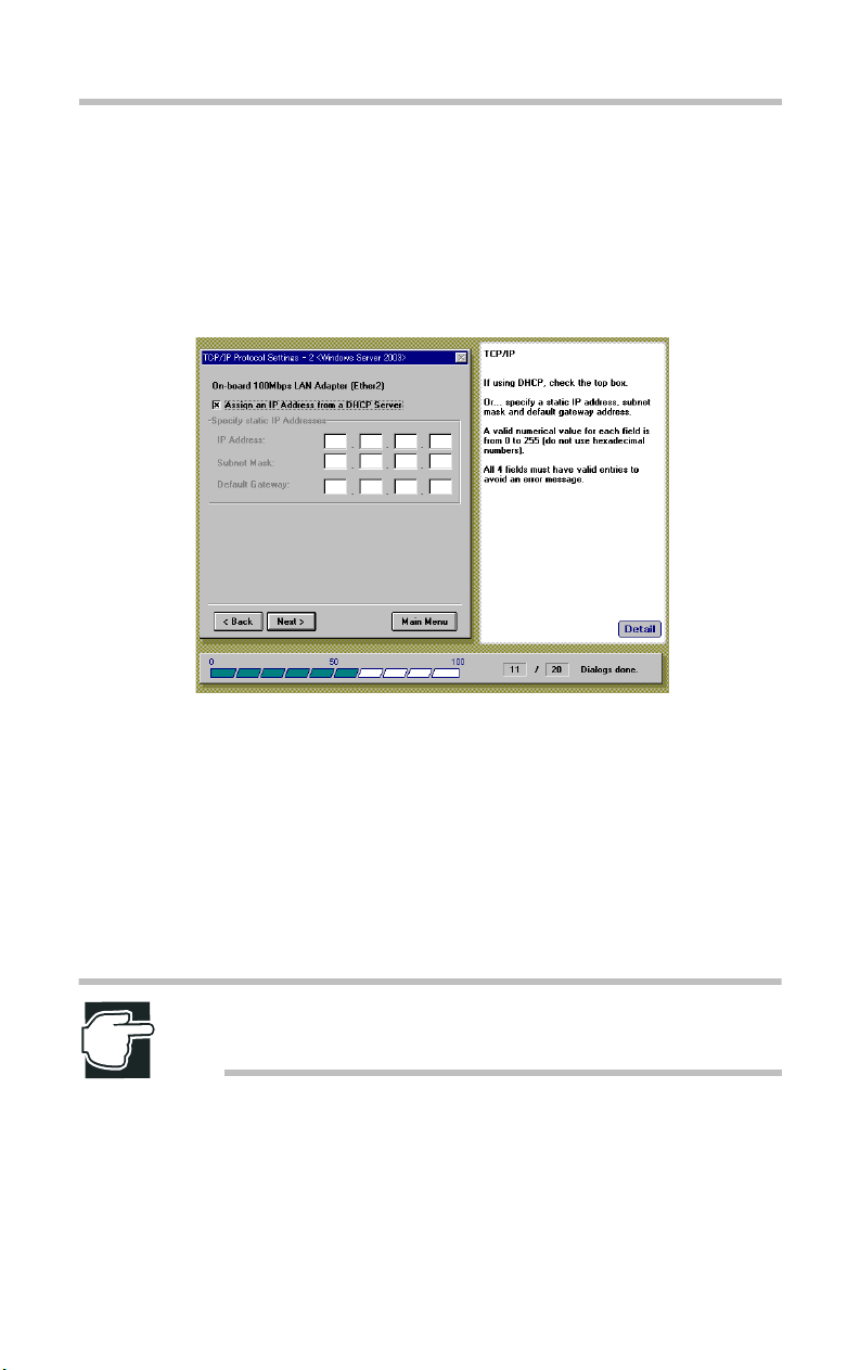
TCP/IP Protocol Settings -2
If you selected the onboard 100Mbit LAN Adapter (Ether2) on
one of the previous screens, this dialog box allows you to specify
the IP address, Subnet Mask and Default Gateway Address for this
Adapter.
TCP/IP Protocol Settings -2 screen
To have a domain server automatically assign the IP addresses,
Subnet Masks and Default Gateway for the On-board 100Mbps
LAN Adapter (Ether2), select "Assign an IP Address from DHCP
Server".
Otherwise, do not select "Assign an IP Address from DHCP
Server" and specify the IP address, Subnet Mask, and Default
Gateway Address.
NOTE: For IP Address, Subnet Mask and Default Gateway
Address, you must use decimal numbers (from 0 to 255).
Page 30
26
Setup
Windows Server 2003 Quick Installation
DNS/WINS Setting -2
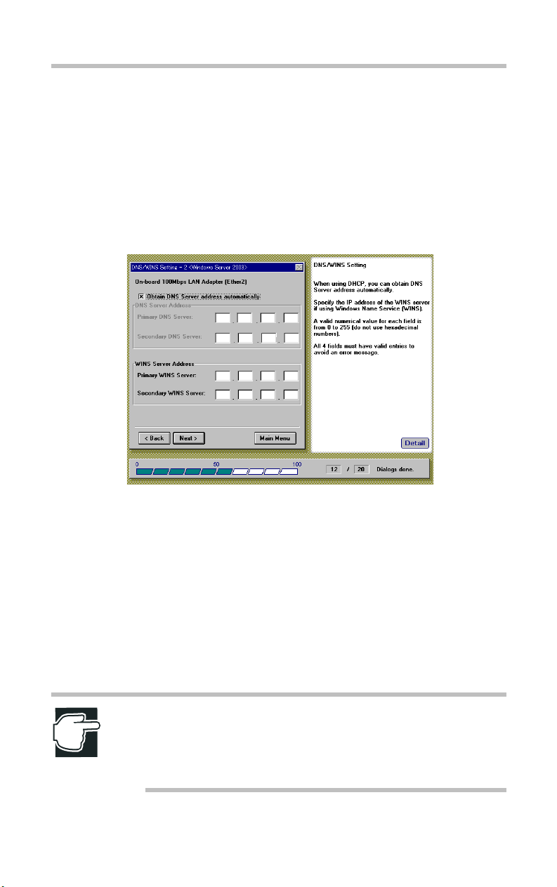
After completing the settings on the TCP/IP Protocol Settings -2
screen, the DNS/WINS Setting -2 screen appears. This screen
allows you to specify the Primary DNS Server Address,
Secondary DNS Server Address, Primary WINS Server Address
and Secondary WINS Server Address for the On-board 100Mbps
LAN Adapter (Ether2).
DNS/WINS Setting -2 screen
If you plan to use the Domain Name System, you may specify the
IP addresses for you DNS servers in the fields "Primary DNS
Server" and "Secondary DNS Server". When using DHCP, you
can obtain the DNS Server address automatically by selecting
"Obtain DNS Server address automatically".
If you are using the Windows Name Service (WINS), enter the IP
address for each of the WINS Servers in the Primary WINS
Server pane and Secondary WINS Server pane.
NOTE: For Primary DNS Server Address, Secondary DNS
Server Address, Primary WINS Server Address and
Secondary WINS Server Address, you must use decimal
numbers (from 0 to 255).
Page 31

Setup
Windows Server 2003 Quick Installation
27
Network Services Setting
In this dialog you can specify which services you would like to
install on Windows 2003.
Network Service Setting screen
Select the network service, then click [Next].
Internet Information Services (IIS)
The Microsoft Internet Information Services.
Dynamic Host Configuration Protocol (DHCP)
This allows a temporary IP address to be assigned to a host
automatically, when the host is connected to the network.
Domain Name System (DNS)
This is a static, hierarchical name service for TCP/IP clients.
Windows Name Service (WINS)
This resolves the NetBIOS computer name to the IP address.
NOTE: When you install the IIS using SST automatic
installation procedure, only the IIS included in the Windows
Server 2003 CD-ROM can be installed. If you want to install
another version of IIS, you must install it manually after the
Windows Server 2003 installation.
Page 32

28
Setup
Windows Server 2003 Quick Installation
Domain/Workgroup Setting
With this dialog you can specify the name of the domain or
workgroup in which your computer takes part.
Domain/Workgroup Setting screen
To specify the domain or workgroup to which your computer
belongs:
1 Enter the name of a domain or a workgroup. To make this
server a part of a domain for the first time, select [Create Computer Account].
2 If the server has already been registered for the domain or you
want to make this server a part of the workgroup, click
[NEXT].
NOTE: If the server has already been registered for the
domain, or you want to make this server a part of the
workgroup, it is not necessary to create a computer account.
3 In the Administrator text box, enter the name of the manager or
administrator account that has the permission to add computers
to the specified domain.
Page 33

Setup
Windows Server 2003 Quick Installation
4 In the Password text box, enter the password of the domain
manager account.
5 In the Confirm Password text box, reenter the password to
confirm it.
NOTE: Do not use double-quote marks (") for all items.
29
Update Driver Settings
After specifying the Domain or Workgroup settings, the Driver
Updates screen appears.
Update Driver Settings screen
SCSI Driver
Activate this checkbox if you have an updated driver for the
onboard SCSI controller.
SCSI RAID Controller Driver
Activate this checkbox if you have an updated driver for the SCSI
RAID Controller. (when neither the MR518 nor the MR520
Page 34

30
Setup
Windows Server 2003 Quick Installation
RAID Controller are installed on your computer, this item will be
unavailable.)
On-board 1Gbps LAN Driver [Ether1]
Activate this checkbox if you have an updated driver for the
onboard 1Gbps LAN Controller.
On-board 100Mbps LAN Driver [Ether2]
Activate this checkbox, if you have updated drivers for the
onboard 100Mbps LAN controller.
NOTE: The drivers for the server hardware are on the Server
Setup TooL CD-ROM. You may, however, have installed
equipment that was shipped with newer drivers on diskettes.
If you need to use the drivers on diskettes, continue with this
section. If you wish to use the drivers from the CD-ROM,
proceed to the next step by clicking [NEXT] without selecting
any item.
NOTE: If you select the "SCSI Driver" or the "SCSI RAID
Controller Driver", a list of devices will be shown on the
screen after inser ting the driver diskette. You must select the
correct device from the list. Refer to the MAGNIA3310 User’s
Guide and the MegaRAID User’s Manual (for MR518 or
MR520) for information about the device name.
Page 35

Setup
Windows Server 2003 Quick Installation
31
Services and Application Installation
Clicking Next on the Update Driver Settings screen displays the
Services and Application Installation screen.
Services and Application Installation screen
HarnessEye/web Agent
This software is used for operational management of the
MAGNIA3310, and can monitor the hardware information for
fault detection. Only the Agent function can be installed using the
SST.
SCSI RAID Utility (MR518 or MR520 only)
The SCSI RAID Controller utility: (if the MR518 and the MR520
are not installed on your computer, this item will be unavailable.)
Power Console
Monitors the RAID configuration.
Service
Extracts log information.
SNMP Agent
Used by TCP/IP-based management applications.
Select the following options:
Page 36

32
Setup
Windows Server 2003 Quick Installation
To install each application automatically, check the [Install]
box.
To install each application driver from the diskette or the CDROM, check the [From FD/CD] box.
NOTE: If you have the latest version on the diskette or the
CD-ROM, check [From FD/CD].
NOTE: To use the other functions (Management Console,
Management Proxy) of the HarnessEye/web, you must install
them manually after the Windows Server 2003 installation.
For more information, refer to the HarnessEye/web User's
Guide (on this Server Setup TooL- and Documentation CD).
Page 37

Setup
Windows Server 2003 Quick Installation
33
HarnessEye/web Setting
If you select the HarnessEye/web on the Services and Application
Installation screen, the HarnessEye/web Setting screen appears.
HarnessEye/web Setting screen
To specify the Management Proxy and the Alias, select [Register
Agent Information].
Management Proxy
Enter the name or the IP address of the Management Proxy Server
to which the Agent is to be registered.
Alias
If you want to assign an alias to the Agent, enter it here.
NOTE: An alias name can be specified by the user. This
makes it easier to specify the node when the node name is a
long string of numbers or letters. For more information, refer
to the HarnessEye/web User's Guide (on this Server Setup
TooL- and Documentation CD).
Page 38

34
Setup
Windows Server 2003 Quick Installation
Schedule of the consistency check (Windows Server
2003)
If you select the SCSI RAID Utility on the Services and
Application Installation screen, the following screen appears.
Schedule of the consistency check
Select the schedule for checking the integrity of the logical drive
redundancy data, then click [Next].
Start time
Specify the time for starting the integrity check. Select from 0 to
23 hours in 1-hour increments.
Start day of the week
Specify the day of the week for performing the integrity check.
Interval
Specify the interval that the integrity check is performed. Intervals
up to 24 weeks can be selected in 1-week increments. When "0" is
selected, the integrity check is performed everyday.
Page 39

Setup
Windows Server 2003 Quick Installation
35
Setup Option
The Setup Option screen appears. Use this screen to specify the
setup installation features you want enabled during the installation
process.
Setup Option screen
Beep sound in case of disk change
Sounds an audible alert (beep) to change storage media (CDROM and diskette).
Start installation according to parameter settings at boot time
When a Configuration Save Disk containing the configuration
information is inserted into the floppy disk drive, and SST is
started up from CD-ROM, a confirmation message is displayed,
and installation is started immediately. The current configuration
information is used. However, if the required devices are not
mounted, device drivers and other information will not be
installed.
Page 40

36
Setup
Windows Server 2003 Quick Installation
Confirm partition information during installation procedure
A dialog box appears, requiring you to confirm the deletion of the
existing partition.
If a disk partition already exists, a confirmation message appears,
asking if you want to delete the partition. If this option is not
checked, setup deletes the partition without prompting you for
confirmation.
NOTE: If you have an existing partition (such as
Windows 2000), the partition is deleted first before
installation.
Confirm Parameter Settings
After you have specified setup installation features, the Confirm
Parameter Settings screen appears. This screen displays a window
listing the configuration and setup parameters that you have
chosen.
Confirm Parameter Settings screen
Review the information displayed on the Confirm Parameter
Settings screen to make sure that it is accurate. To change a setting,
Page 41

Setup
Windows Server 2003 Quick Installation
highlight the item you wish to change and click Jump. The setup
wizard will return to that screen and allow you to make changes.
If you are satisfied with the installation settings, click Execute.
To save configuration information, select [Execute] and then
[Yes]. Setup is started after the configuration information is saved
to the Configuration Save Disk.
NOTE: After finishing the OS installation, continue the setup
according to the procedure described in [Chapter 2 After
Installation (Windows Server 2003)].
NOTE: In order to save composition information at
Configuration Save Disk, the Floppy Disk Drive needs to be
connected beforehand.
The former contents are eliminated when composition
information is saved at Configuration Save Disk.
37
Page 42

Setup
38
Windows 2000 Quick Installation
Windows 2000 Quick Installation
Locale Settings
NOTE: When you select the "Install Windows 2000 - Quick
installation" option, the following Locale Settings screen
appears.
Locale Settings screen
Select a Language for your Operating System.
NOTE: You must select the same OS language as your OS
CD-ROM. Once you have chosen a specific language [i.e.
French] for the SST installation of Windows 2000, do not
attempt to install a different language [i.e. Spanish] version of
Windows 2000 or the installation will fail.
Page 43

Setup
Windows 2000 Quick Installation
Create Disk Partition
After specifying the Locale Settings, the Create Disk Partition
screen appears.
Create Disk Partition screen
39
Select a file system.
FAT 16
Creates the file system using the FAT16 (File Allocation Table
with 16-bit entries) format.
NTFS
Creates the file system using the NTFS (NT File System) format.
Input Partition Size
Enter the size of the disk partition you want to create, then press
[Enter].
Page 44

40
Setup
Windows 2000 Quick Installation
NOTE: If you select "FAT16", SST will create a partition with a
size of 2048MB.
NOTE: If you select "NTFS" and enter a partition size larger
than available space on the disk, SST will create a partition
with 2048MB default size.
NOTE: If you select "NTFS", you must specify the disk
partition size larger than the sum of the installed system
memory plus 830MB. Moreover, if you want to install
Windows 2000 Service Pack, you must specify a value larger
than the sum of the installed system memory plus 1.6GB.
NOTE: If you select "FAT16", you cannot install Windows
2000 Service Pack using SST.
Page 45

Setup
Windows 2000 Quick Installation
User Information Settings
After specifying the disk partition parameters, the User
Information Settings screen appears.
User Information Settings screen
41
Enter the following user settings:
User Name
Name of the user (administrator).
Organization
Company or organization name (optional).
Product ID/CD Key
Product ID or CD-key of the Windows 2000 CD-ROM.
Computer Name
Identifies the computer to the rest of the network. The identifying
name should be 15 alphanumeric characters or less.
NOTE: To set up the Computer Name, you must use one or
more alphabetic characters.
Page 46

42
Setup
Windows 2000 Quick Installation
License Mode Setting
After specifying the User Information Settings, the License Mode
Setting screen appears.
License Mode Setting screen
You can structure the operating system license in one of two ways:
Per Server Mode
The server's license specifies the number of clients.
The number of users for a server should be no less than the
number of client computers that can simultaneously connect to
that server.
Per Seat Mode
Each client computer (seat) has its own license, which allows it to
access any Windows 2000 on the network.
Select one of the two license modes and click [Next] after the
setting.
NOTE: If you are not sure which license mode to use, select
"Per Server Mode". The license mode can be changed once
only from "Per Server Mode" to "Per Seat Mode", based on
the contract for the license.
Page 47

Setup
Windows 2000 Quick Installation
Server Role Setting
After specifying the License Mode Setting, the Server Role
Setting screen appears.
Server Role setting screen
43
Select one of the options, then click [Next].
Domain Member
Configures the computer as part of a domain, controlled by a
domain controller.
Workgroup
User accounts and resources are controlled by the individual
computers.
NOTE: To make your server a domain controller, you must
install Active Directory after the Windows 2000 Server
installation. See section [After Installation (Windows 2000)] in
Chapter 2.
Page 48

44
Setup
Windows 2000 Quick Installation
LAN Adapter Selection
After specifying the Server Role, the LAN Adapter Selection
screen appears.
LAN Adapter Selection screen
Select the LAN Adapter being used, then click [Next].
On-board 1Gbps LAN Adapter (Ether1)
This adapter is compatible with 1000BASE-T/100BASE -TX/
10BASE-T Ethernet LAN.
Page 49

Setup
Windows 2000 Quick Installation
On-board 100Mbps LAN Adapter (Ether2)
This adapter is compatible with 100BASE -TX/10 BASE-T
Ethernet LAN.
NOTE: The [Onboard 1Gbps LAN Adapter (Ether1)] option is
always selected.
NOTE: The LAN driver for onboard LAN adapter (Ether2)
must be installed regardless of the setting of this screen. If the
[Onboard 100Mbps LAN Adapter (Ether2)] option is not
selected, onboard LAN adapter (Ether2) will be set up using
the default setting of Windows 2000.
Network Protocol Setting -1
45
After specifying the LAN Adapter, the Network Protocol Setting 1 screen appears. Use this screen to specify the network
communication protocol for the On-board 1Gbps LAN Adapter
(Ether1).
Network Protocol Setting -1 screen
Page 50

46
Setup
Windows 2000 Quick Installation
Select the communication protocol for On-board 1Gbps LAN
Adapter (Ether1), then click [Next].
TCP/IP Protocol
Transmission control protocol
Internet protocol
NetBEUI Protocol
NetBIOS expansion user interface
NOTE: If you select "TCP/IP Protocol", the SNMP service will
be automatically installed.
Page 51

Setup
Windows 2000 Quick Installation
47
TCP/IP Protocol Settings -1
If you have specified TCP/IP as the network communication
protocol on the Network Protocol Setting -1 screen, the TCP/IP
Protocol Settings -1 screen appears. The TCP/IP Protocol Settings
-1 screen allows you to specify the IP Address, Subnet Mask, and
Default Gateway Address for On-board 1Gbps LAN Adapter
(Ether1).
TCP/IP Protocol Settings -1 screen
To complete the TCP/IP protocol settings for On-board 1Gbps
LAN Adapter (Ether1), enter the IP Address for On-board 1Gbps
LAN Adapter (Ether1).
To have a DHCP server automatically assign the IP addresses,
Subnet Masks and Default Gateway for On-board 1Gbps LAN
Adapter (Ether1), select "Assign an IP Address from DHCP
Server".
Otherwise, do not select "Assign an IP Address from DHCP
Server" and specify manually the IP address, Subnet Mask, and
Default Gateway Address.
NOTE: For IP Address, Subnet Mask and Default Gateway
Address, you must use decimal numbers (from 0 to 255).
Page 52

48
Setup
Windows 2000 Quick Installation
DNS/WINS Setting -1
After completing the settings on the TCP/IP Protocol Settings -1
screen, the DNS/WINS Setting -1 screen appears. This screen
allows you to specify the Primary DNS Server Address,
Secondary DNS Server Address, Primary WINS Server Address
and Secondary WINS Server Address for the On-board 1Gbps
LAN Adapter (Ether1).
DNS/WINS Setting -1 screen
If you plan to use the Domain Name System, you may specify the
IP addresses for your DNS servers in the fields "Primary DNS
Server" and "Secondary DNS Server". When using DHCP, you
can obtain the DNS Server address automatically by selecting
"Obtain DNS Server address automatically".
If you are using the Windows Name Service (WINS), enter the IP
address for each of the WINS Servers in the Primary WINS
Server pane and Secondary WINS Server pane.
NOTE: For Primary DNS Server Address, Secondary DNS
Server Address, Primary WINS Server Address and
Secondary WINS Server Address, you must use decimal
numbers (from 0 to 255).
Page 53

Setup
Windows 2000 Quick Installation
49
Network Protocol Setting -2
If you selected the onboard 100Mbit LAN Adapter (Ether2) on
one of the previous screens, this dialog box allows you to specify
the network communication protocol for the onboard 100Mbps
LAN Adapter (Ether2).
Network Protocol Setting -2 screen
Select the communication protocol for On-board 100Mbps LAN
Adapter (Ether2), then click [Next].
TCP/IP Protocol
Transmission control protocol
Internet protocol
NetBEUI Protocol
NetBIOS expansion user interface
NOTE: If you select "TCP/IP Protocol", the SNMP service will
be automatically installed.
Page 54

50
Setup
Windows 2000 Quick Installation
TCP/IP Protocol Settings -2
If you have specified TCP/IP as the network communication
protocol on the Network Protocol Setting -2 screen, this screen
appears. The TCP/IP Protocol Settings -2 screen allows you to
specify the IP Address, Subnet Mask and Default Gateway
Address for On-board 100Mbps LAN Adapter (Ether2).
TCP/IP Protocol Settings -2 screen
To complete the TCP/IP protocol settings for the On-board
100Mbps LAN Adapter (Ether2), enter the IP Address for Onboard 100Mbps LAN Adapter (Ether2).
To have a DHCP server automatically assign the IP addresses,
Subnet Masks and Default Gateway for the On-board 100Mbps
LAN Adapter (Ether2), select "Assign an IP Address from DHCP
Server".
Otherwise, do not select "Assign an IP Address from DHCP
Server" and specify the IP address, Subnet Mask, and Default
Gateway Address.
NOTE: For IP Address, Subnet Mask and Default Gateway
Address, you must use decimal numbers (from 0 to 255).
Page 55

Setup
Windows 2000 Quick Installation
51
DNS/WINS Setting -2
After completing the settings on the TCP/IP Protocol Settings -2
screen, the DNS/WINS Setting -2 screen appears. This screen
allows you to specify the Primary DNS Server Address,
Secondary DNS Server Address, Primary WINS Server Address
and Secondary WINS Server Address for On-board 100Mbps
LAN Adapter (Ether2).
DNS/WINS Setting -2 screen
If you plan to use the Domain Name System, you may specify the
IP addresses for your DNS servers in the fields "Primary DNS
Server" and "Secondary DNS Server". When using DHCP, you
can obtain the DNS Server address automatically by selecting
"Obtain DNS Server address automatically".
If you are using the Windows Name Service (WINS), enter the IP
address for each of the WINS Servers in the Primary WINS
Server pane and Secondary WINS Server pane.
NOTE: For Primary DNS Server Address, Secondary DNS
Server Address, Primary WINS Server Address and
Secondary WINS Server Address, you must use decimal
numbers (from 0 to 255).
Page 56

52
Setup
Windows 2000 Quick Installation
Network Services Setting
If you have specified TCP/IP as the network communication
protocol on the Network Protocol Setting screen, the Network
Services Setting screen appears.
Network Service Setting screen
Select the network service, then click [Next].
Internet Information Services (IIS)
The Microsoft Internet Information Services.
Dynamic Host Configuration Protocol (DHCP)
This allows a temporary IP address to be assigned to a host
automatically, when the host is connected to the network.
Domain Name System (DNS)
This is a static, hierarchical name service for TCP/IP clients.
Windows Name Service (WINS)
This resolves the NetBIOS computer name to the IP address.
NOTE: When you install the IIS using SST automatic
installation procedure, only the IIS included in the Windows
2000 CD-ROM can be installed. If you want to install another
version of IIS, you must install it manually after the Windows
2000 installation.
Page 57

Setup
Windows 2000 Quick Installation
53
Domain/Workgroup Setting
The name of the domain or workgroup in which your computer
takes part.
If you selected TCP/IP as your networking protocol, this screen
appears after completing the screen "Network Services Settings".
If you did not enable TCP/IP, this screen is displayed after
"Network Protocol Settings".
Domain/Workgroup Setting screen
To specify the domain or workgroup to which your computer
belongs:
1 Enter the name of a domain or a workgroup. To make this
server a part of a domain for the first time, select [Create Computer Account].
2 If the server has already been registered for the domain or you
want to make this server a part of the workgroup, click
[NEXT].
NOTE: If the server has already been registered for the
domain, or you want to make this server a part of the
workgroup, it is not necessary to create a computer account.
Page 58

54
Setup
Windows 2000 Quick Installation
3 In the Administrator text box, enter the name of the manager or
administrator account that has the permission to add computers
to the specified domain.
4 In the Password text box, enter the password of the domain
manager account.
5 In the Confirm Password text box, reenter the password to
confirm it.
NOTE: Do not use double-quote marks (") for all items.
Page 59

Setup
Windows 2000 Quick Installation
55
Update Driver Settings
After specifying the Domain or Workgroup settings, the Driver
Updates screen appears.
Update Driver Settings screen
SCSI Driver
Activate this checkbox if you have an updated driver for the
onboard SCSI controller.
SCSI RAID Controller Driver
Activate this checkbox if you have an updated driver for the SCSI
RAID Controlle. (when neither the MR518 nor the MR520 RAID
Controller are installed on your computer, this item will be
unavailable.)
On-board 1Gbps LAN Driver [Ether1]
Activate this checkbox if you have an updated driver for the
onboard 1Gbps LAN Controller.
On-board 100Mbps LAN Driver [Ether2]
Activate this checkbox, if you have updated drivers for the
onboard 100Mbps LAN controller.
Page 60

56
Setup
Windows 2000 Quick Installation
NOTE: The drivers for the server hardware are on the Server
Setup TooL CD-ROM. You may, however, have installed
equipment that was shipped with newer drivers on diskettes.
If you need to use the drivers on diskettes, continue with this
section. If you wish to use the drivers from the CD-ROM,
proceed to the next step by clicking [NEXT] without selecting
any item.
NOTE: If you select the "SCSI Driver" or the "SCSI RAID
Controller Driver", a list of devices will be shown on the
screen after inser ting the driver diskette. You must select the
correct device from the list. Refer to the MAGNIA3310 User’s
Guide and the MegaRAID User’s Manual(for MR518 or
MR520) for information about the device name.
Page 61

Setup
Windows 2000 Quick Installation
57
Services and Application Installation
Clicking Next on the Update Driver Settings screen displays the
Services and Application Installation screen.
Services and Application Installation screen
HarnessEye/web Agent
This software is used for operational management of the
MAGNIA3310, and can monitor the hardware information for
fault detection. Only the Agent function can be installed using the
SST.
SCSI RAID Utility (MR518 or MR520 only)
The SCSI RAID Controller utility: (if the MR518 and the MR520
are not installed on your computer, this item will be unavailable.)
Power Console
Monitors the RAID configuration.
Service
Extracts log information.
SNMP Agent
Used by TCP/IP-based management applications.
Page 62

58
Setup
Windows 2000 Quick Installation
Windows 2000 Service Pack
Windows 2000 Service Pack. If you selected [FAT16] on the
Create Disk Partition screen, this item will be unavailable.
Select the following options:
To install each application automatically, check the [Install]
box.
To install each application driver from the diskette or the CDROM, check the [From FD/CD] box.
NOTE: If you have the latest version on a diskette or the CDROM, check [From FD/CD]. If you do not select "TCP/IP
protocol" (then SNMP ser vice is also not installed), the SNMP
agent of SCSI RAID utility cannot be installed.
NOTE: To use the other functions (Management Console,
Management Proxy) of the HarnessEye/web, you must install
them manually after the Windows 2000 installation. For more
information, refer to the HarnessEye/web User's Guide (on
this Server Setup TooL- and Documentation CD).
NOTE: Windows 2000 Service Pack is not included in the
SST CD-ROM. To install the Windows 2000 Service Pack, the
CD-ROM including self-executable file of Windows 2000
Service Pack is needed.
Page 63

Setup
Windows 2000 Quick Installation
NOTE: To install Windows 2000 Service Pack, the remaining
capacity of the hard disk drive must be about 770MB or more.
You must specify the disk partition size larger than the sum of
installed system memory (RAM) plus 1.6GB on the Create
Disk Partition screen.
NOTE: The Intel Chipset Software Installation Utility,
TOSHBA Display Power Save Driver and Display driver
contained on the SST CD-ROM are automatically installed
when the OS is installed. If you have obtained a newer
version, manually update the software after installing the OS.
59
Page 64

60
Setup
Windows 2000 Quick Installation
HarnessEye/web Setting
If you select the HarnessEye/web on the Services and Application
Installation screen, the HarnessEye/web Setting screen appears.
HarnessEye/web Setting screen
To specify the Management Proxy and the Alias, select [Register
Agent Information].
Management Proxy
Enter the name or the IP address of the Management Proxy Server
to which the Agent is to be registered.
Alias
If you want to assign an alias to the Agent, enter it here.
NOTE: An alias name can be specified by the user. This
makes it easier to specify the node when the node name is a
long string of numbers or letters. For more information, refer
to the HarnessEye/web User's Guide (on this Server Setup
TooL- and Documentation CD).
Page 65

Setup
Windows 2000 Quick Installation
61
Schedule of the consistency check (Windows 2000)
If you select the SCSI RAID Utility on the Services and
Application Installation screen, the following screen appears.
Schedule of the consistency check
Select the schedule for checking the integrity of the logical drive
redundancy data, then click [Next].
Start time
Specify the time for starting the integrity check. Select from 0 to
23 hours in 1-hour increments.
Start day of the week
Specify the day of the week for performing the integrity check.
Interval
Specify the interval that the integrity check is performed. Intervals
up to 24 weeks can be selected in 1-week increments. When "0" is
selected, the integrity check is performed everyday.
Page 66

62
Setup
Windows 2000 Quick Installation
Setup Option
The Setup Option screen appears. Use this screen to specify the
setup installation features you want enabled during the installation
process.
Setup Option screen
Beep sound in case of disk change
Sounds an audible alert (beep) to change storage media (CDROM and diskette).
Start installation according to parameter settings at boot time
When a Configuration Save Disk containing the configuration
information is inserted into the floppy disk drive, and SST is
started up from CD-ROM, a confirmation message is displayed,
and installation is started immediately. The current configuration
information is used. However, if the required devices are not
mounted, device drivers and other information will not be
installed.
Page 67

Setup
Windows 2000 Quick Installation
Confirm partition information during installation procedure
A dialog box appears, requiring you to confirm the deletion of the
existing partition.
If a disk partition already exists, a confirmation message appears,
asking if you want to delete the partition. If this option is not
checked, setup deletes the partition without prompting you for
confirmation.
NOTE: If you have an existing partition (such as
Windows 2000), the partition is deleted first before
installation.
63
Confirm Parameter Settings
After you have specified setup installation features, the Confirm
Parameter Settings screen appears. This screen displays a window
listing the configuration and setup parameters that you have
chosen.
Confirm Parameter Settings screen
Page 68

64
Setup
Windows 2000 Quick Installation
Review the information displayed on the Confirm Parameter
Settings screen to make sure that it is accurate. To change a setting,
highlight the item you wish to change and click Jump. The setup
wizard will return to that screen and allow you to make changes.
If you are satisfied with the installation settings, click Execute.
To save configuration information, select [Execute] and then
[Yes]. Setup is started after the configuration information is saved
to the Configuration Save Disk.
NOTE: After finishing the OS installation, continue the setup
according to the procedure described in [Chapter 2 After
Installation (Windows 2000)].
NOTE: In order to save composition information at
Configuration Save Disk, the Floppy Disk Drive needs to be
connected beforehand.
The former contents are eliminated when composition
information is saved at Configuration Save Disk.
Page 69

Setup
Windows Server 2003 Manual Installation using SST
65
Windows Server 2003 Manual Installation using
SST
When [Install Windows Server 2003 - Manual Installation] is
selected from the [Operating System Installation Selection] menu,
the RAID system is automatically configured, and the diskettes for
manual installation are automatically created. For more
information about Windows Server 2003 Standard Edition/
Windows Server 2003 Enterprise Edition installation, refer to the
MAGNIA3310 User's Guide (on this Server Setup TooL- and
Documentation CD).
Following disks are automatically created by the SST:
Adaptec SCSI Windows Server 2003 Driver
<Windows Server 2003>
Intel 1Gbps LAN Windows Server 2003 Driver
<Windows Server 2003>
Intel 100Mbps LAN Windows Server 2003 Driver
<Windows Server 2003>
Page 70

Setup
66
Windows 2000 Manual Installation using SST
Windows 2000 Manual Installation using SST
When [Install Windows 2000 - Manual Installation] is selected
from the [Operating System Installation Selection] menu, the
RAID system is automatically configured, and the diskettes for
manual installation are automatically created. For more
information about Windows 2000/Windows 2000 Advanced
Server installation, refer to the MAGNIA3310 User's Guide (on
this Server Setup TooL- and Documentation CD).
Following disks are automatically created by the SST:
Adaptec SCSI Windows 2000 Driver <Windows 2000>
Intel 1Gbps LAN Windows 2000 Driver <Windows 2000>
Intel 100Mbps LAN Windows 2000 Driver <Windows 2000>
Page 71

Setup
Windows Server 2003/Windows 2000 Manual Installation without using SST
Windows Server 2003/Windows 2000 Manual
Installation without using SST
To install the Windows Server 2003 Standard Edition/Windows
Server 2003 Enterprise Edition or Windows 2000/Windows 2000
Advanced Server without using the Toshiba Server Setup TooL's
automatic installation procedure, you must create some diskettes
for manual installation from the "Create Floppy Disks" menu.
After creating the diskettes, follow your MAGNIA3310 User's
Guide installation instructions (on this Server Setup TooL- and
Documentation CD).
Create Floppy Disks for Manual Installation
1 Start the SST using one of the procedures shown below.
[Chapter 3 Starting the Utilities program from SST
CD-ROM]
67
[Chapter 3 Starting the Utilities on another system]
2 Select the [Utilities] option in the "Main Menu".
Utility Menu screen
Page 72

68
Setup
Windows Server 2003/Windows 2000 Manual Installation without
using SST
3 Select [Create Floppy Disks] option and following items, then
select [Create].
Adaptec SCSI Windows Server 2003 Driver
<Windows Server 2003>
Intel 1Gbps LAN Windows Server 2003 Driver
<Windows Server 2003>
Intel 100Mbps LAN Windows Server 2003 Driver
<Windows Server 2003>
Adaptec SCSI Windows 2000 Driver <Windows 2000>
Intel 1Gbps LAN Windows 2000 Driver <Windows 2000>
Intel 100Mbps LAN Windows 2000 Driver<Windows 2000>
Create Floppy Disks screen
4 Insert an unused diskette, then select [OK].
5 After creating the diskettes, you must label the diskettes. To
check the label descriptions, select [Detail] -> [Create Floppy
Disks] and see the SST Help.
NOTE: Use 2HD blank diskettes for creating the installation
disks.
Page 73

Setup
After Installation (Windows Server 2003)
After Installation (Windows Server 2003)
If you have finished Windows Server 2003 installation, then
follow the steps below:
Confirming and Setting up the Time Zone
1 Start Windows Server 2003 and log on as Administrator (or a
user having equivalent rights).
2 Run Date/Time Properties by clicking Start, Settings,
Control panel, and double clicking on Date/Time.
3 Click Time Zone tab.
4 Check that the current Time Zone setting is correct. If
incorrect, select the correct setting and press [OK].
Setting up the Physical Address Extension
69
To set up the Physical Address Extension, refer to your MAGNIA
3310 User's Guide. You only need to do this if you have more than
4GB of System Memory installed.
Setting up the Active Directory (To make this server
as a domain controller)
If you installed the TCP/IP protocol and you want to designate this
server as a domain controller in your network, you must install
Active Directory.
For more information about Active Directory, refer to the
Windows Server 2003 Help.
Page 74

70
Setup
After Installation (Windows Server 2003)
Setting up the AFT/ALB function
The onboard LAN controllers support the AFT/ALB function.
To setup the AFT/ALB function, refer to your MAGNIA3310
User’s Guide.
Page 75

After Installation (Windows 2000)
After Installation (Windows 2000)
If you have finished Windows 2000 installation, then follow the
steps below:
Confirming and Setting up the Time Zone
1 Start Windows 2000 and log on as Administrator (or a user
having equivalent rights).
2 Run Date/Time Properties by clicking Start, Settings,
Control panel, and double clicking on Date/Time.
3 Click Time Zone tab.
4 Check that the current Time Zone setting is correct. If
incorrect, select the correct setting and press [OK].
Installing the Windows 2000 Service Pack
Setup
71
If you do not perform a quick installation of the Windows 2000
Service Pack, you have to install it manually for attached devices
and installed software to work correctly.
Setting up the Physical Address Extension
To set up the Physical Address Extension, refer to your MAGNIA
3310 User's Guide.You only need to do this if you have more than
4GB of System Memory installed.
Setting up the SAF-TE Controller
Make the following setting only when the hard disk drive is
connected to the onboard SCSI controller. For details on how to
setup the SAF-TE controller, refer to the MAGNIA3310 User’s
Guide.
Page 76

72
Setup
After Installation (Windows 2000)
Setting up the Active Directory (To make this server
as a domain controller)
If you installed the TCP/IP protocol and you want to designate this
server as a domain controller in your network, you must install
Active Directory.
For more information about Active Directory, refer to the
Windows 2000 Help.
Setting up the AFT/ALB function
The onboard LAN controllers support the AFT/ALB function.
To setup AFT/ALB function, refer to your MAGNIA3310 User’s
Guide.
Page 77

Chapter 3
How to Start Utilities .................................................................. 75
Utility Menu ................................................................................ 79
Page 78

Utilities
This chapter describes how to use the Toshiba Utilities.
74
Page 79

How to Start Utilities
About Utilities
The utilities option allows you to customize the installation, create
the diskettes, and manage the RAID configuration. The Utilities
Menu screen contains two panes, providing the following utilities:
Setup Support
- Setup Information
- Create Floppy Disks
HW Setup
- RAID Configuration
NOTE: There are two ways to start the Utilities. Some utility
programs cannot be executed according to either way. Items
which are unavailable cannot be executed.
Utilities
How to Start Utilities
75
NOTE: To use [Setup Information] and [Create Floppy Disks],
the floppy disk drive must be connected.
Starting the Utilities program from SST CD-ROM
1 Make certain that the monitor, keyboard, mouse and all periph-
erals are correctly connected.
2 Turn on the power button on this server, and immediately
insert the SST CD-ROM into the CD-ROM drive.
3 The Server Setup TooL starts the Main Menu, and then you
can select the [Utilities] option.
Page 80

Utilities
76
How to Start Utilities
Selectable items when the Utilities program is started from SST CD-ROM
Selectable items
Setup Information
Create Floppy Disks
RAID Configuration
Utility Menu screen (started from the SST CD-ROM)
Page 81

How to Start Utilities
Starting the Utilities on another system
1 Insert the SST CD-ROM on a machine where Windows 2000,
Windows NT, Windows Me, Windows 98 or Windows 95 is
running.
2 After a while, the Input Locale screen appears, then select one
of the keyboard layouts.
3 After finishing the locale setting, the SST Main menu appears.
Selectable items when the Utilities is started from another
system
Selectable items
Setup Information
Create Floppy Disks
Utilities
77
Utility Menu screen (started from another system)
Page 82

78
Utilities
How to Start Utilities
NOTE: When the Server Setup TooL has been started on
another system, only the Utilities of the Main menu can be
selected. If the Auto-Run function is not allowed, the Server
Setup TooL does not start automatically on that system.
NOTE: To use all the functions on the Utility menu, a floppy
disk drive is required.
Page 83

Utility Menu
Setup Support
Setup Information
Clicking [Setup Information] starts the Setup Information wizard
and opens the Setup Wizard dialog box where you select how the
SST configures the server, RAID, and operating system during the
installation procedure. This menu reads the current setting
information from the SST Configuration Save Disk and arranges
the settings.
NOTE: To save the configuration information you create on a
Configuration Save Diskette, click [Save] on the Confirm
Settings page.
Utilities
Utility Menu
79
Page 84

80
Utilities
Utility Menu
Create Floppy Disks
Clicking [Create Floppy Disks] lists the system boot, diagnostic,
and installation diskettes you can create from the Utilities menu.
Create Floppy Disks screen
There are the following check boxes in the Create Floppy Disks
screen.
Checking a specific box displays the corresponding diskette
entries in the list.
Windows Server 2003
Lists the diskette titles that are necessary for installing the
Windows Server 2003 Standard Edition/Windows Server 2003
Enterprise Edition.
Windows 2000
Lists the diskette titles that are necessary for installing the
Windows 2000 Server/Windows 2000 Advanced Server.
OTHER
Lists all diskette titles except ones for Windows Server 2003
Standard Edition/Windows Server 2003 Enterprise Edition and
Windows 2000 Server/Windows 2000 Advanced Server.
Page 85

Utilities
Utility Menu
Available Diskettes
The following diskettes can be created from the "Create Floppy
Disks" menu.
NOTE: Use 2HD blank diskettes for creating the installation
disks.
Configuration Save Disk
This diskette is used to save the setup information for
MAGNIA3310.
DOS Disk
This diskette is used to starts the utility programs used on the
server.
Hardware Diagnostics Program
This diskette is used to boot from the floppy disk drive and run
Hardware diagnostics.
The Hardware Diagnostics Program checks the operation of the
hardware and the input/output devices and displays the
configuration information of the system.
81
Adaptec SCSI Windows Server 2003 Driver
This diskette is used on Windows Server 2003 for the
MAGNIA 3310 onboard SCSI controller.
Adaptec SCSI Windows 2000 Driver
This diskette is used on Windows 2000 for the MAGNIA 3310
onboard SCSI controller.
Intel 1Gbps LAN Windows Server 2003 Driver
This diskette is used on Windows Server 2003 for the
MAGNIA 3310 onboard 1Gbps LAN controllers (Ether1).
Intel 1Gbps LAN Windows 2000 Driver
This diskette is used on Windows 2000 for the MAGNIA 3310
onboard 1Gbps LAN controllers (Ether1).
Intel 100Mbps LAN Windows Server 2003 Driver
This diskette is used on Windows Server 2003 for the
MAGNIA 3310 onboard 100Mbps LAN controllers (Ether2).
Page 86

82
HW Setup
Utilities
Utility Menu
Intel 100Mbps LAN Windows 2000 Driver
This diskette is used on Windows 2000 for the MAGNIA3310
onboard 100Mbps LAN controllers (Ether2).
Create Floppy disks
1 Select the title of the diskette you want to create, then click
[Create] to continue.
2 Insert a blank diskette according to the instruction.
RAID Configuration
The RAID Manager starts by selecting [RAID Configuration].
Creating, repairing and deleting RAID configuration, and creating
a hot-spare disk are available in the RAID Manager.
For more information, refer to the MegaRAID User's Manual.
Page 87

Chapter 4
About Hardware Diagnostics .................................................... 85
Starting the Hardware Diagnostics Program .......................... 85
Items of Hardware Diagnostics ................................................ 86
Page 88

Hardware Diagnostics
This chapter describes how to use the Hardware Diagnostics
Program.
84
Page 89

Hardware Diagnostics
About Hardware Diagnostics
About Hardware Diagnostics
Hardware Diagnostics starts a diagnostics test of the server's
hardware devices. You can select a single device or a combination
of devices to test.
Use the Hardware Diagnostics Program to check:
Whether the server operates normally.
For anything abnormal or any failure while the server is in use.
Whether or not optional devices are working normally.
Starting the Hardware Diagnostics Program
Starting up with the diskette
NOTE: If you have not created the Hardware Diagnostics
Program diskette, create it from [Utilities] - [Create Floppy
Disks].
85
1 Make certain that the monitor, keyboard, mouse and all periph-
erals are correctly connected.
2 Insert the Hardware Diagnostics Program diskette. (Set the dis-
kette writable.)
3 Turn on the power of the server.
The Hardware Diagnostics Program starts.
Page 90

Hardware Diagnostics
86
Items of Hardware Diagnostics
Items of Hardware Diagnostics
When any key is pressed on the initial screen of the Toshiba
Hardware Diagnostics Program, the main Hardware Diagnostics
Program menu appears:
Main menu of Hardware Diagnostics Program
[01.DIAGNOSTIC TEST]
Test hardware.
For more information, refer to [Chapter 4 Items of Hardware
Diagnostics - Diagnostics Test (01. DIAGNOSTIC TEST)].
[02.RUNNING TEST]
Automatically execute the Diagnostics tests in a user-defined
sequence.
For more information, refer to [Chapter 4 Items of Hardware
Diagnostics - Running Test (02. RUNNING TEST)].
[03. LOG UTILITIES]
Displays the error information.
For more information, refer to [Chapter 4 Log Utilities)].
[04.SYSTEM CONFIGURATION]
Displays the system configuration.
For more information, refer to [Chapter 4 System Configuration
Display].
Page 91
Hardware Diagnostics
Items of Hardware Diagnostics
[99.EXIT]
Terminates the Hardware Diagnostics Program, then the server
reboots and the SST Menu appears.
Diagnostics Test (01. DIAGNOSTIC TEST)
1 From Diagnostics Test Menu (DIAGNOSTIC TEST MENU)
screen, select the desired subtest number from the subtest
menu. (To return to the Main Menu, select "99" or "Esc".)
NOTE: Even if the testing device does not exist on your
computer, [06.SCSI HDD TEST] can be executed, however
nothing is tested.
01 MEMORY TEST
02 KEYBOARD TEST
03 DISPLAY TEST
04 FLOPPY DISK TEST
05 PRINTER TEST
06 SCSI HDD TEST
07 NPX TEST
08 CACHE MEMORY TEST
09 SCSI TEST
10 CD-ROM TEST
11 SAF-TE TEST
12 BMC TEST
99 EXIT TO DIAGNOSTICS MENU
87
2 After selecting the desired subtest, the following message will
appear.
(For more detail information for each item, refer to [Chapter 4
Items of Hardware Diagnostics - Details of Test items and
Error Log Information]):
Page 92

88
Hardware Diagnostics
Items of Hardware Diagnostics
Diagnostics TEST - TEST PARAMETER
[01.Go to Test]
Start the test. If you need to stop the test program, press <Ctrl> +
<Pause>.
[02.Test Loop]
Selecting "YES" increments the pass counter each time the test
cycle ends, and restarts the test cycle.
Selecting "NO" returns the subtest menu to the main menu after
the test is completed.
[03.Error Stop]
Selecting "YES" stops the test program when an error is detected.
Selecting "NO" keeps the test running even if an error is detected.
Running Test (02.RUNNING TEST)
The following test parameter appears when you select "02
RUNNING TEST".
(To return to the Main Menu, select "99" or "Esc".)
Running TEST - TEST PARAMETER
Page 93

Hardware Diagnostics
Items of Hardware Diagnostics
89
[01.Go to Test]
To start the running test. If you need to stop the test program, press
<Ctrl> + <Pause>.
[02.Test ITEM EDIT]
To choose the test items under the RUNNING Test.
[03.Finish BUZZER Sound]
When the Server finishes the running test, the beep sounds.
[99.Exit to DIAGNOSTICS MENU]
To return to the Hardware Diagnostics Main Menu.
In the initial setting, the following items are automatically
executed:
01.MEMORY TEST 01.Conventional memory
03.DISPLAY TEST 01.VRAM W/R/C
03.DISPLAY TEST 02.640*480 Mode display
03.DISPLAY TEST 03.1024*768 Mode display
06.SCSI HDD TEST 02.Connection
07.NPX TEST 01.NPX test
08.CACHE TEST 01.Constant data test
08.CACHE TEST 02.Address pattern test
08.CACHE TEST 03.Increment / Decrement test
08.CACHE TEST 04.Caching data test
10.CD-ROM TEST 02.Random address read
11.SAF-TE TEST 01.SAF-TE test
04.FLOPPY DISK TEST 01.Sequential address read
Page 94

90
Hardware Diagnostics
Items of Hardware Diagnostics
When the test is completed, the test result appears on the screen in
large text.
No error has been detected OK
The test has been compulsorily ended, or any error has been
detected.
NOTE: To check the error log, select [03.LOG UTILITIES] in
the main menu. For the key operation on the error log display,
refer to "Checking error log" in this chapter. If the test in
progress has been stopped, the test result is not displayed.
FAI LE D
Selecting Items of Running Test
A screen appears when you select [02. TEST ITEM EDIT]. This
menu shows the current items in the running test, and will allow
you to add or delete individual tests.
NOTE: Even if the testing device does not exist on your
computer, [06.SCSI HDD TEST], [09.SCSI TEST] and
[11.SAF-TE TEST] can be added, however nothing is tested.
TEST ITEM EDIT FOR RUNNING TEST
Page 95

Hardware Diagnostics
Items of Hardware Diagnostics
91
Adding Test Items
To add a test item to the Running test, press <Ins> key, then select
a test item with arrow keys, and press <Enter> to select subtests.
To return to the previous menu, press <Esc> key.
NOTE: Do not add the subtest [01. Pressed Key Display] of
[02. KEYBOARD TEST] to the Running test. This subtest
requires a key input so that the Running test in progress is
stopped if this subtest is added to the Running test.
Do not select only the subtest [08. CACHE MEMORY TEST]
as the Running test.
Deleting Test Items
Move the cursor on a test item, then press <Del> to delete the test
item.
Saving Test Items
When you exit the test items selection menu, the message "Do you
save data?" appears. Select "YES" to save settings, or "NO" not to
save the settings.
NOTE: The edited test items are saved on the system
memory. When you restart the Hardware Diagnostics
Program, the test items will return to the initial settings.
Execution of Test
During DIAGNOSTIC TEST and RUNNING TEST, the
following screen appears:
Page 96

92
Hardware Diagnostics
Items of Hardware Diagnostics
Sample screen during the test
XXX TEST
Indicates the name of the test being executed.
SUB-TEST
Indicates the subtest number, and the step number of the test being
executed.
ERROR COUNT
Indicates the error count of the test.
PASS COUNT
Indicates the pass count of the test.
WRITE DATA
Indicates the written data.
READ DATA
Indicates the read-data.
ADDRESS
Indicates the address of the test being executed.
STATUS
Indicates the status of the test being executed.
If any error occurs during the test, the message "ERROR
OCCURRED!" is displayed. The error name is also displayed
under the message "ADDRESS".
Page 97

Hardware Diagnostics
Items of Hardware Diagnostics
93
Details of Test Items and Error Log Information
The following are Test items and Error log information:
[01. MEMORY TEST]
To run the memory.
[01. Conventional memory]
This test writes data to conventional memory (0 to 640 KB), then
reads the new data and compares the result with the test data.
[02. Expansion memory]
This test writes constant data to all the memory area, then reads the
data and compares it with the test data.
[03. RAM refresh]
This test writes test data to the memory, then reads the data after
one refresh cycle and compares the data with the test data.
[04. Stress test]
This test writes data to the protected mode memory (from 1 MB to
maximum), then reads the data and compares it with the written
data.
NOTE: The [02. Expansion memory], [03. RAM refresh] and
[04. Stress test] test all memory area. When the capacity of
mounted memory is large, the tests may take a few hours.
MEMORY TEST (RAM) Error log
Status Error name Meaning
01 PARITY ERROR Parity error
02 PROTECTED MODE NOT
CHANGE ERROR
FF DATA COMPARE ERROR Data comparing error
The Shift to the protected mode failed
Page 98

94
Hardware Diagnostics
Items of Hardware Diagnostics
[02. KEYBOARD TEST]
The Keyboard Test contains three subtests that test the computer's
keyboard and mouse actions.
[01. Pressed key display]
When you execute this subtest, the keyboard layout is drawn
on the display. When any key is pressed, the corresponding key
appears on the display. Pressing and holding a key enables the
auto-repeat function which causes the key's displayed
character to blink.
Before executing the test, select Keyboard Type in the test
parameters.
[02. Keyboard LED on]
The system flashes the Num Lock, Caps Lock, and Scroll
Lock LEDs.
[03. PS/2 Mouse]
This subtest checks whether a PS/2 mouse is connected or not.
During the test, no message appears on the screen.
KEYBOARD TEST (KBD) Error log
Status Error name Meaning
01 CLOCK LINE ERROR L Clock line error (LOW)
02 CLOCK LINE ERROR H Clock line error (HIGH)
03 DATA LINE ERROR L Data line error (LOW)
04 DATA LINE ERROR H Data line error (HIGH)
07 INTERFACE ERROR Interface error
08 RESENDING ERROR Sending/receiving error
09 ID ERROR ID error
FF DATA COMPARE ERROR Data comparing error
Page 99

Hardware Diagnostics
Items of Hardware Diagnostics
[03. DISPLAY TEST]
To test the function of the display.
[01. VRAM W/R/C]
This subtest writes constant data to video RAM. This data is
then read from the video RAM, and it is compared with the
original data.
[02. 640*480 Mode display]
This subtest displays data in 256 color display mode in 640 *
480 resolution.
[03. 1024*768 Mode display]
The test data is displayed in 256 color display mode in 1,024 *
768 resolution.
DISPLAY TEST (CRT) Error Log
Status Error name Meaning
FF DATA COMPARE ERROR Data comparing error
95
[04.FLOPPY DISK TEST]
To test the floppy disk drive, prepare a formatted floppy disk.
Before starting the test, select the following parameters:
Test Drive number
Designates the floppy disk drive to drive A or B.
This server does not support the drive B. Select drive A.
Media type
Designates the format type (1.44 MB or 720 KB) of the diskette
for the test.
This system does not support the 1.2 MB format type.
Test start track number
Designates the first track number for the test.
Page 100

96
Hardware Diagnostics
Items of Hardware Diagnostics
At the start of the test, the message to change the Hardware
Diagnostics test diskette with the test diskette appears. Change
disks at this point.
[01. Sequential address read]
This subtest reads data from all tracks continuously on a
diskette.
[02. Random address data W/R/C]
This subtest writes random data to random addresses on all
tracks on the diskette. The data is then read and compared to
the original data.
NOTE: This test requires that the test diskette be formatted
and write-enabled.
Make sure that there is no important data on the test diskette,
as the contents may be modified during the test.
FLOPPY DISK TEST (FDD) Error log
Status Error name Meaning
01 BAD COMMAND ERROR Bad command error has occurred
02 ADDRESS MARK NOT FOUND The address mark has not been found
03 WRITE PROTECED Floppy disk is write-protected
04 RECORD NOT FOUND The record has not been found
06 MEDIA CHANGE LINE ERROR The media change line is bad
08 DMA OVERRUN ERROR DMA OVERRUN occurred
09 DMA BOUNDARY ERROR DMA BOUDARY occurred
10 CRC ERROR CRC check error
20 FDC ERROR FDC error
40 SEEK ERROR Floppy disk seek error
*Address during the test (ADDRESS: 0tthss)
0 tt h ss
tt : Track address
h : Head address
ss : Sector address
 Loading...