

Toshiba 32EL833G Schematic
SERVICE MANUAL
LCD Color Television
Print this page
32EL833G
TOSHIBA WEB-ZEUS
Ver. 1.01
Updating history
Amendment by DS Company
Updating History,
2011-06-13 Amendment done by DS Company
Correction of the contents
>> terms and conditions >> privacy policy
Copyright © 1995-2011 TOSHIBA Corporation, All Rights Reserved.
5
6

Print this page
IMPORTANT NOTICE
WARNING:
You are requested that you shall not modify or alter the information or data provided herein without prior written consent by Toshiba.
Toshiba shall not be liable to anybody for any damages, losses, expenses or costs, if any, incurred in connection with or as a result
of such modification or alteration.
THE INFORMATION OR DATA HEREIN SHALL BE PROVIDED "AS IS" WITHOUT ANY WARRANTY OF ANY KIND, EITHER EXPRESS
OR IMPLIED WARRANTY OF MERCHANTABILITY AND FITNESS FOR A PARTICULAR PURPOSE.
Toshiba shall not be liable for any damages, losses, expenses or costs, if any, incurred in connection with or as a result of use of any
information or data provided herein.
TOSHIBA WEB-ZEUS
>> terms and conditions >> privacy policy
Copyright © 1995-2011 TOSHIBA Corporation, All Rights Reserved.

Print this page
GREEN PRODUCT PROCUREMENT
The EC is actively promoting the WEEE & RoHS Directives that define standards for recycling and reuse of Waste Electrical and Electronic
Equipment and for the Restriction of the use of certain Hazardous Substances. From July 1, 2006, the RoHS Directive will prohibit any marketing
of new products containing the restricted substances.
Increasing attention is given to issues related to the global environmental. Toshiba Corporation recognizes environmental protection as a key
management tasks, and is doing its utmost to enhance and improve the quality and scope of its environmental activities. In line with this, Toshiba
proactively promotes Green Procurement, and seeks to purchase and use products, parts and materials that have low environmental impacts.
Green procurement of parts is not only confined to manufacture. The same green parts used in manufacture must also be used as replacement
parts.
TOSHIBA WEB-ZEUS
>> terms and conditions >> privacy policy
Copyright © 1995-2011 TOSHIBA Corporation, All Rights Reserved.

Print this page
LEAD-FREE SOLDER
This product is manufactured using lead-free solder as a part of a movement within the consumer products industry at large to be environmentally
responsible. Lead-free solder must be used in the servicing and repair of this product.
WARNING: This product is manufactured using lead free solder.
DO NOT USE LEAD BASED SOLDER TO REPAIR THIS PRODUCT!
The melting temperature of lead-free solder is higher than that of leaded solder by 86ºF to 104ºF (30ºC to 40ºC). Use of a soldering iron designed
for lead-based solders to repair product made with lead-free solder may result in damage to the component and or PCB being soldered. Great
care should be made to ensure high-quality soldering when servicing this product especially when soldering large components, through-hole pins,
and on PCBs as the level of heat required to melt lead-free solder is high.
TOSHIBA WEB-ZEUS
>> terms and conditions >> privacy policy
Copyright © 1995-2011 TOSHIBA Corporation, All Rights Reserved.
Print this page
SAFETY INSTRUCTION
WARNING: BEFORE SERVICING THIS CHASSIS, READ THE "SAFETY PRECAUTION" AND "PRODUCT SAFETY NOTICE"
INSTRUCTIONS BELOW.
Safety Precaution
WARNING: SERVICING SHOULD NOT BE ATTEMPTED BY ANYONE UNFAMILIAR WITH THE NECESSARY PRECAUTIONS ON THIS
RECEIVER. THE FOLLOWING ARE THE NECESSARY PRECAUTIONS TO BE OBSERVED BEFORE SERVICING THIS CHASSIS.
1. An isolation transformer should be connected in the power line between the receiver and the AC line before any service is performed on the
receiver.
2. Always disconnect the power plug before any disassembling of the product. It may result in electrical shock.
3. When replacing a chassis in the cabinet, always be certain that all the protective devices are put back in place, such as nonmetallic control
knobs, insulating covers, shields, isolation resistor-capacitor network, etc.
4. Always keep tools, components of the product, etc away from the children, These items may cause injury to children.
5. Depending on the model, use an isolation transformer or wear suitable gloves when servicing with the power on, and disconnect the power
plug to avoid electrical shock when replacing parts. In some cases, alternating current is also impressed in the chassis, so electrical shock is
possible if the chassis is contacted with the power on.
6. Always use the replacement parts specified for the particular model when making repairs. The parts used in products require special safety
characteristics such as inflammability, voltage resistance, etc. therefore, use only replacement parts that have these same characteristics.
Use only the specified parts when the mark is indicated in the circuit diagram or parts list.
7. Parts mounting and routing dressing of wirings should be the same as that used originally. For safety purposes, insulating materials such as
isolation tube or tape are sometimes used and printed circuit boards are sometimes mounted floating. Also make sure that wirings is routed
and clamped to avoid parts that generate heat and which use high voltage. Always follow the manufactured wiring routes / dressings.
8. Always ensure that all internal wirings are in accordance before re-assembling the external casing after a repairing completed. Do not allow
internal wiring to be pinched by cabinets, panels, etc. Any error in reassembly or wiring can result in electrical leakage, flame, etc., and may
be hazardous.
9. NEVER remodel the product in any way. Remodeling can result in improper operation, malfunction, or electrical leakage and flame, which
may be hazardous.
10. Touch current check. (After completing the work, measure touch current to prevent an electric shock.)
Plug the AC cord directly into the AC outlet. Do NOT use an isolation transformer for this check.
Connect a measuring network for touch currents between each exposed metallic part on the set and a good earth ground such as a
water pipe.
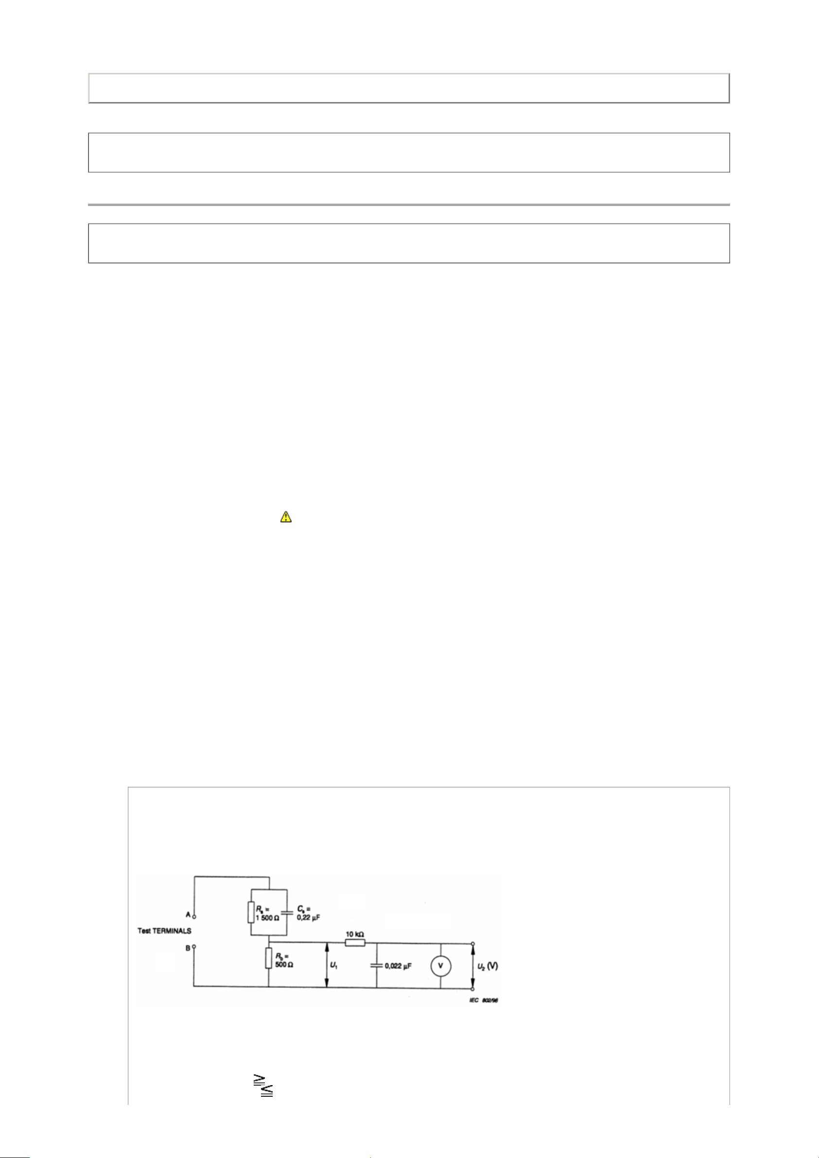
Annex D
(normative)
Measuring network for TOUCH CURRENTS
Resistance values in orms (Ω).
V: Voltmeter or oscilloscope
(r.m.s. or peak reading)
Input resistance : 1 MΩ
Input capacitance : 200 pF
Frequency range : 15 Hz to 1 MHz and d.c. respectively
Note: Appropriate measures should be taken to obtain the correct value in case of non sinusoidal waveforms.
The measuring instrument is calibrated by comparing the frequency factor of with the solid line in figure F.2 of IEC 60990 at
various frequencies. A calibration curve is constructed showing the deviation of from the ideal curve as a function of frequency.
TOUCH CURRENT = / 500 (peak value).
The potential at any point (TOUCH CURRENT) expressed as voltage and does not exceed the following value:
The part or contact of a TERMINAL is not HAZARDOUS LIVE if:
a) The open-circuit voltage should not exceed 35 V (peak) a.c. or 60 V d.c. or, if a) is not met.
b) The measurement of the TOUCH CURRENT shall be carried out in accordance with IEC 60990, with the measuring network
described in Annex D of this standard.
The TOUCH CURRENT expressed as voltages and , does not exceed the following values:
- for a.c. : = 35 V (peak) and = 0.35 V (peak);
- for d.c. : = 1.0 V
Note: The limit values of = 0.35 V (peak) for a.c. and = 1.0 V for d.c. correspond to the values 0.7 mA (peak) a.c. and 2.0 mA
d.c.
TOSHIBA WEB-ZEUS
>> terms and conditions >> privacy policy
Copyright © 1995-2011 TOSHIBA Corporation, All Rights Reserved.

Print this page
SAFETY INSTRUCTION
Product Safety Notice
Many electrical and mechanical parts in this chassis have special safety-related characteristics. These characteristics are often passed unnoticed
by a visual inspection and the protection afforded by them cannot necessarily be obtained by using replacement components rated for higher
voltage, wattage, etc. Replacement parts which have these special safety characteristics are identified in this manual and its supplements;
electrical components having such features are identified by the international hazard symbols on the schematic diagram and the parts list.
Before replacing any of these components, read the parts list in this manual carefully. The use of substitute replacement parts which do not have
the same safety characteristics as specified in the parts list may create electrical shock, fire, or other hazards.
TOSHIBA WEB-ZEUS
>> terms and conditions >> privacy policy
Copyright © 1995-2011 TOSHIBA Corporation, All Rights Reserved.
Print this page
SAFETY INSTRUCTION
Handling the LCD Module
Safety Precaution
In the event that the screen is damaged or the liquid crystal (fluid) leaks, do not breathe in or drink this fluid.
Also, never touch this fluid. Such actions could cause toxicity or skin irritation. If this fluid should enter the mouth, rinse the mouth thoroughly with
water. If the fluid should contact the skin or clothing, wipe off with alcohol, etc., and rinse thoroughly with water. If the fluid should enter the eyes,
immediately rinse the eyes thoroughly with running water.
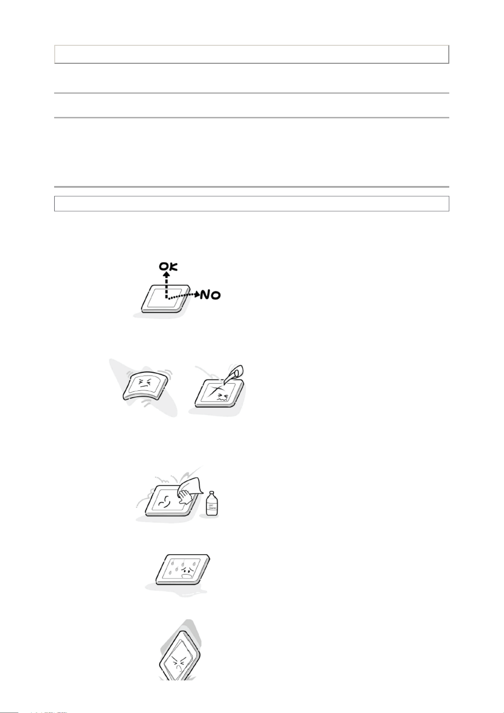
Precautions for Handling the LCD Module
CAUTION: The metal edges of the LCD module are sharp, handle it with care.
The LCD module can easily be damaged during disassembly or reassembly; therefore, always observe the following precautions when handling
the module.
1. When attaching the LCD module to the LCD cover, position it appropriately and fasten at the position where the display can be viewed most
conveniently.
2. Carefully align the holes at all four corners of the LCD module with the corresponding holes in the LCD cover and fasten with screws. Do not
strongly push on the module because any impact can adversely affect the performance. Also use caution when handling the polarized
screen because it can easily be damaged.
3. If the panel surface becomes soiled, wipe with cotton or a soft cloth. If this does not remove the soiling, breathe on the surface and then wipe
again.
If the panel surface is extremely solied, use a CRT cleaner as a cleaner. Wipe off the panel surface by drop the cleaner on the cloth. Do not
drop the cleaner on the panel. Pay attention not to scratch the panel surface.
4. Leaving water or other fluids on the panel screen for an extended period of time can result in discoloration or stripes. Immediately remove
any type of fluid from the screen.
5. Glass is used in the panel, so do not drop or strike with hard objects. Such actions can damage the panel.
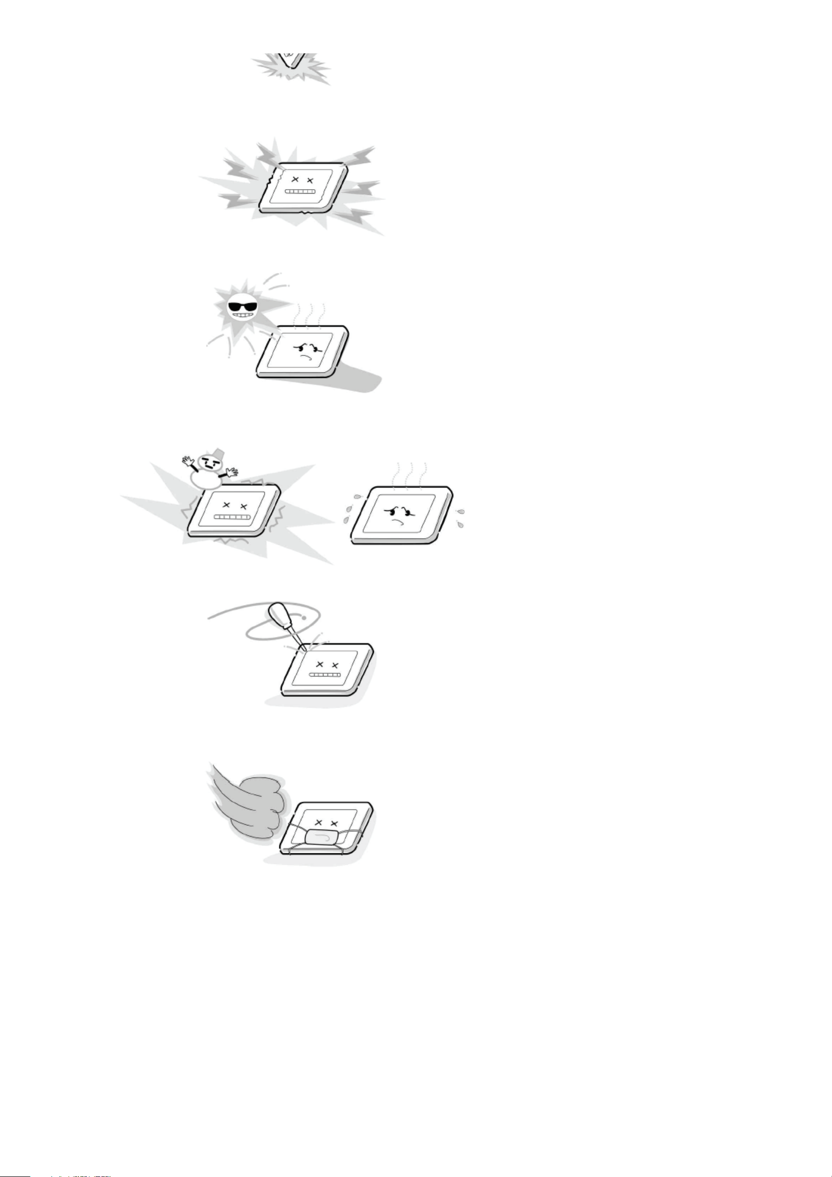
6. CMOS-LSI circuitry is used in the LCD module, so avoid damage due to static electricity. When handling the module, use a wrist ground or
anchor ground.
7. Do not expose the LCD module to direct sunlight or strong ultraviolet rays for an extended period of time.
8. Do not store the LCD module below the temperature conditions described in the specifications. Failure to do so could result in freezing of the
liquid crystal due to cold air or loss of resilience or other damage.
9. Do not disassemble the LCD module. Such actions could result in improper operation.
10. When transporting the LCD module, do not use packing containing epoxy resin (amine) or silicon resin (alcohol or oxim). The gas generated
by these materials can cause loss of polarity.
TOSHIBA WEB-ZEUS
>> terms and conditions >> privacy policy
Copyright © 1995-2011 TOSHIBA Corporation, All Rights Reserved.
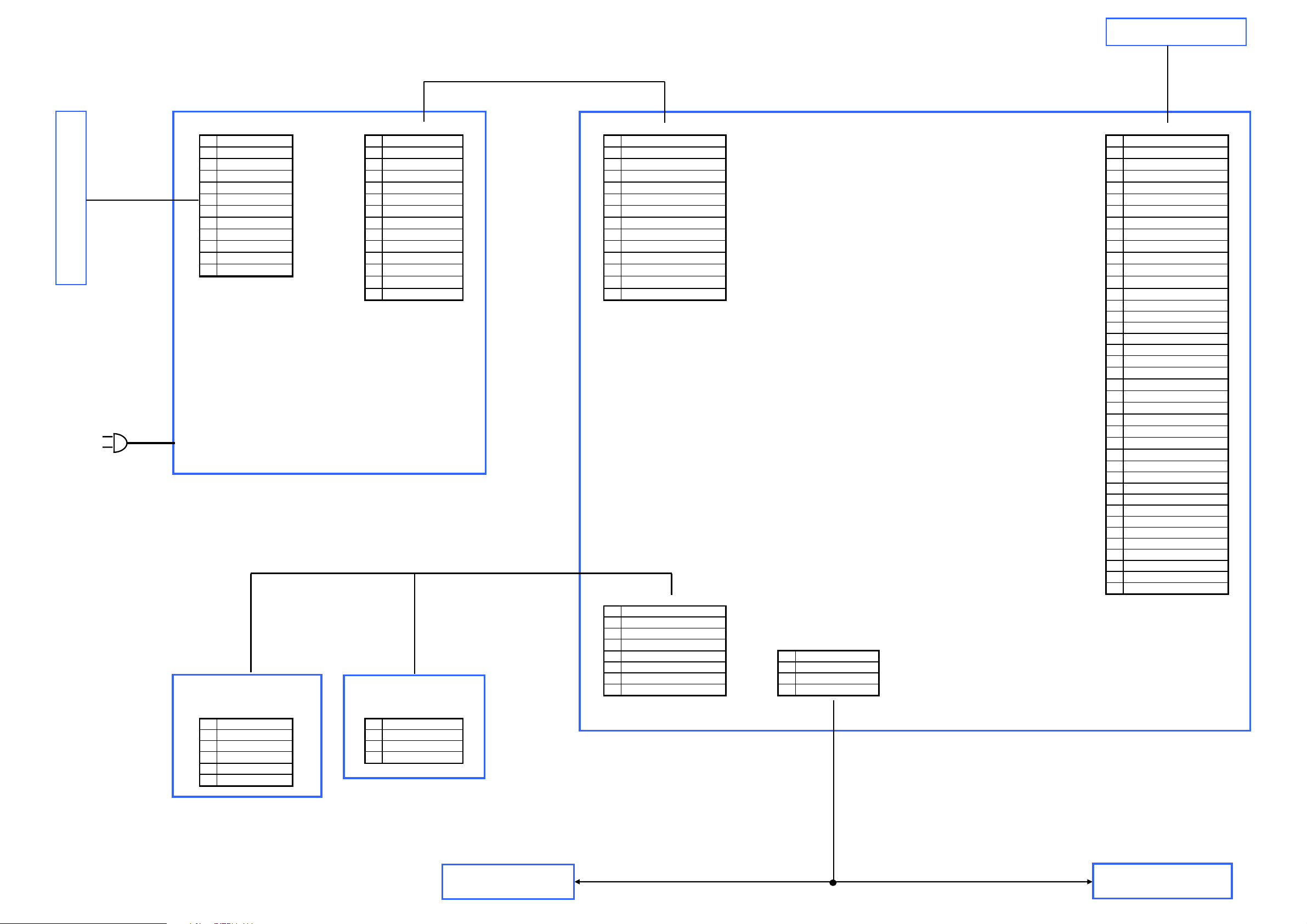
P201 P202 CN1 CN12
1 24V 1 12V 1 +12V_NORMAL 1 PANEL_VCC
2 24V 2 12V 2 +12V_NORMAL 2 PANEL_VCC
3 24V 3 12V 3 +12V_NORMAL 3 PANEL_VCC
4 24V 4 GND 4 GND 4 PANEL_VCC
5 24V 5 GND 5 GND 5 OD_OCP_SEL
6 GND 6 GND 6 GND 6 PANEL_VCC
7 GND 7 5VSB 7 +5V_Standby 7 RXE4+
8 GND 8 5VSB 8 +5V_Standby 8 GND
9 GND 9 5VSB 9 +5V_Standby 9 RXE3+
10 GND 10 ACD 10 ACDetect 10 RXE411 BRIGHT_ADJ 11 BD_PS_ON 11 BD_POWER_ON 11 RXEC+
12 INV_ON_OFF 12 BRIGHT_ADJ 12 OCP_OUTPUT_PWM 12 RXE3-
13 INV_ON_OFF 13 INVERTER_ON_OFF 13 GND
14 PS_ON 14 STANDBY 14 RXEC-
15 RXE2+
16 GND
17 RXE1+
18 REX219 REX0+
20 REX121 GND
22 REX023 RXO4+
24 GND
25 RXO3+
26 RXO427 RXOC+
28 RXO329 GND
30 RXOC31 RXO2+
32 GND
33 RXO1+
34 RXO235 RXO0+
36 RXO137 GND
38 RXO039 BRIGHT_ADJ
40 OCP_OUTPUT_PWM
CN2
1 +5V_Standby
2 KEY0
3 KEY1
4 GND CN11
5 IRIN 1 SPK_R6 LED_ON_OFF 2 SPK_R+
7 LED_TIMER 3 SPK_L8 GND 4 SPK_L+
CN202 CON1
1 +5V_STBY 1 KEY2
2 GND 2 KEY1
3 RC_IR 3 GND
4 GND 4 GND
5 LED_ON_OFF
6 LED_TIMER
IR_LED BORAD
Speaker
MAIN BOARD
PSU Unit
PANEL (T-CON)
PANEL_INVERTER
KEY BORAD
Speaker

TROUBLESHOOTING GUIDE
UNDER CONSTRUCTION
Note: Please check back in the future.
Print this page
TOSHIBA WEB-ZEUS
>> terms and conditions >> privacy policy
Copyright © 1995-2011 TOSHIBA Corporation, All Rights Reserved.
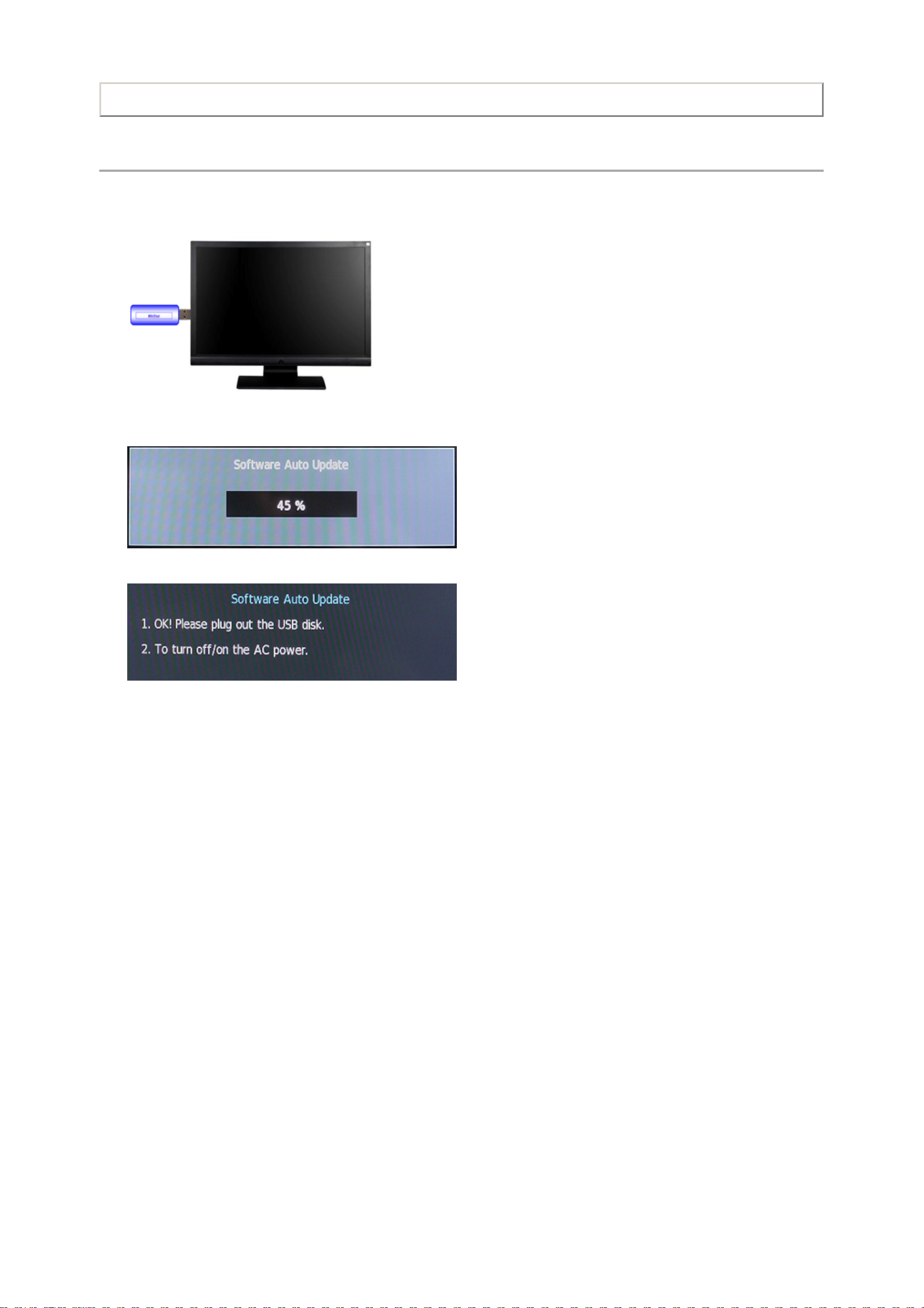
FIRMWARE UPDATING PROCEDURE
Firmware Upgrade - USB
1. Copy a firmware BIN file to USB disk. (Root directory)
2. Plug USB disk into TV USB port.
Print this page
3. Reboot (AC Off/On) TV to upgrade firmware automatically. During firmware upgrade, OSD will be displayed on LCD screen, and power
status LED will be blinking.
4. When firmware upgrade is finished, a message will be displayed on screen.
5. Unplug USB disk, and turn AC Off/On to reboot TV.
Note:
This upgrade method is available only when boot code exists in flash memory (Main Board).
TOSHIBA WEB-ZEUS
>> terms and conditions >> privacy policy
Copyright © 1995-2011 TOSHIBA Corporation, All Rights Reserved.
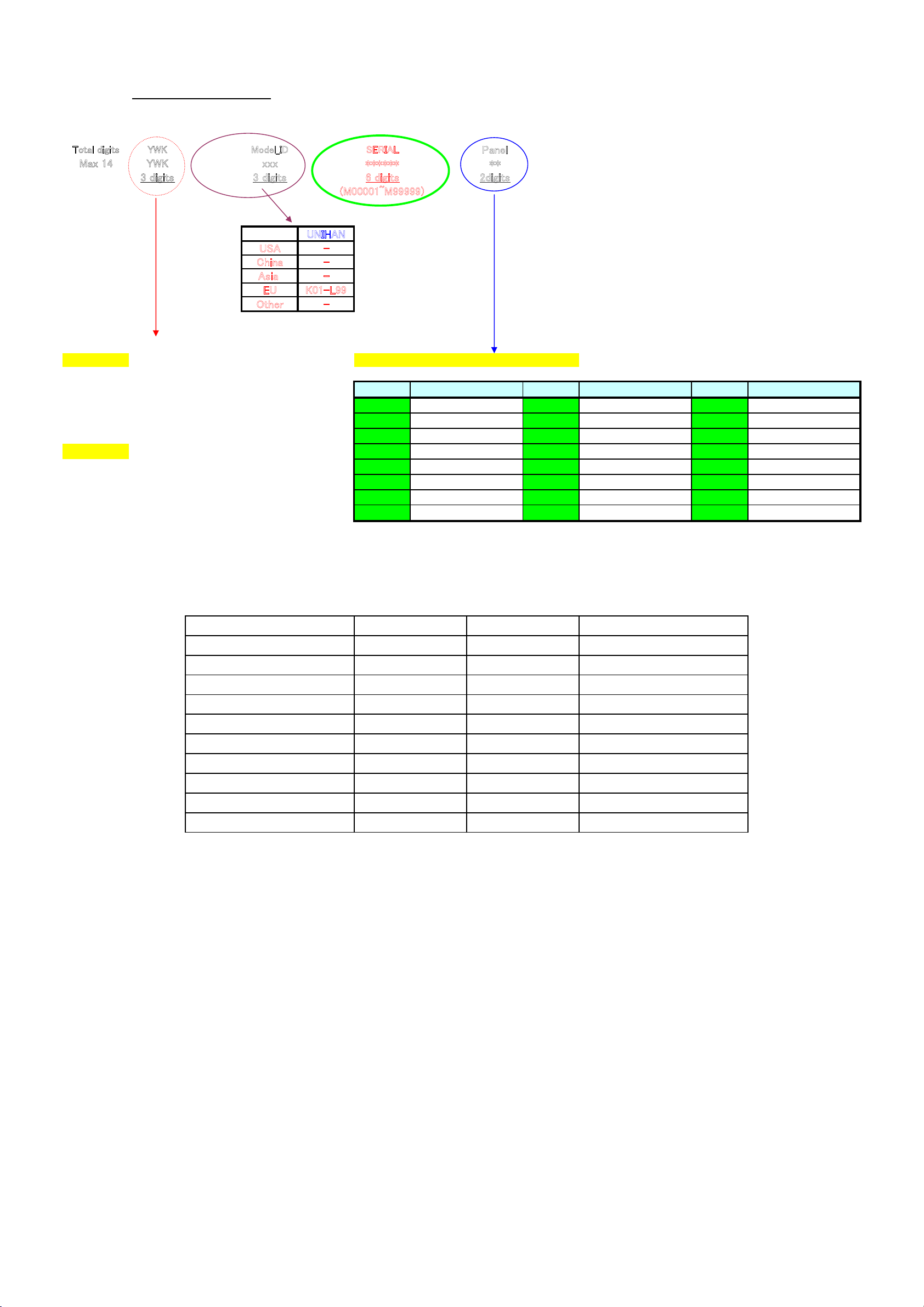
Global Serial No.
㪫㫆㫋㪸㫃㩷㪻㫀㪾㫀㫋㫊㪰㪮㪢㪤㫆㪻㪼㫃㪶㪠㪛㪪㪜㪩㪠㪘㪣
㪧㪸㫅㪼㫃
㪤㪸㫏㩷㪈㪋㪰㪮㪢㫏㫏㫏㪁㪁㪁㪁㪁㪁㪁㪁
㪊㩷㪻㫀㪾㫀㫋㫊㪊㩷㪻㫀㪾㫀㫋㫊㪍㩷㪻㫀㪾㫀㫋㫊㪉㪻㫀㪾㫀㫋㫊
㩿㪤㪇㪇㪇㪇㪈㫕㪤㪐㪐㪐㪐㪐㪀
㪬㪥㪠㪟㪘㪥
㪬㪪㪘㪄
㪚㪿㫀㫅㪸㪄
㪘㫊㫀㪸㩷㪄
㪜㪬㪢㪇㪈㪄㪣㪐㪐
㪦㫋㪿㪼㫉㪄
Y:Year 8 2008 Panel vendor and version for the model.
9 2009
A 2010
Marking Marking Marking
B 2011
A J S
C 2012
B K T
…
…
C L U
WK䋺Week 01 WK01
D M V
02 WK02
E N W
03 WK03
F P X
04 WK04
G Q Y
…
…
H R Z
53 WK53
Model Information
L1
L1
L1
L1
L1
L1
L1
L1
L1
K42
K43
K44 LC320EXN-SDA2
LC320EXN-SDA2
LC320EXN-SDA2
LC320EXN-SDA2
LC320EXN-SDA2
LC260EXN-SDA3
LC260EXN-SDA3
LC260EXN-SDA3
LC260EXN-SDA3
Panel ID Panel
L1 LC260EXN-SDA3K35
Model ID
K36
K37
K39
K70
K40
K41
32EL833F
32EL833N
32EL833R
26EL833R
26EL833RB
32EL833B
32EL833G
Model
26EL833B
26EL833G
26EL833F
Panel Vendor
AUO
CMO
Panel Vendor
SAMSUNG
LPL/LGD
CPT
IPS
Panel Vendor
SHARP
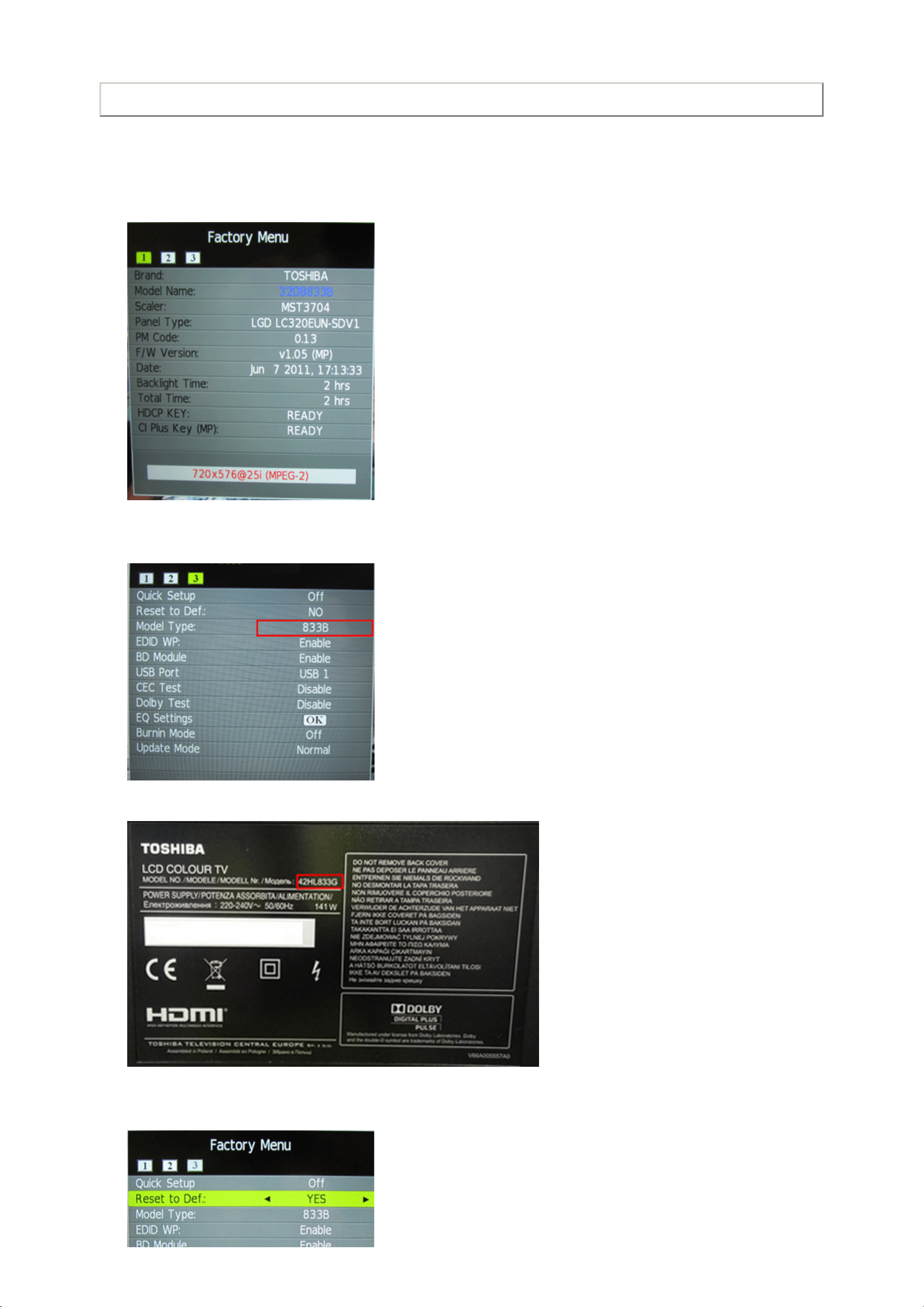
DESTINATION SETTING CHANGE
Whenever replacing the Main PCB with new one, perform this procedure.
1. Press "Mute" key twice on the Remote.
2. Press "Menu" button on the TV set. Then the OSD is displayed.
Print this page
3. Move to Tag "3" by Right/Left Arrow key on the Remote.
4. Select "Model Type" cell.
5. Select the appropriate model type by Right/Left Arrow key on the Remote. Model type is written on the rating label.
6. Select "Reset to Def".
7. Select "Yes" and press "OK" button on the Remote.

TOSHIBA WEB-ZEUS
>> terms and conditions >> privacy policy
Copyright © 1995-2011 TOSHIBA Corporation, All Rights Reserved.
Print this page
PARTS LIST
Precaution
WARNING: BEFORE SERVICING THIS CHASSIS, READ THE "SAFETY PRECAUTION" AND "PRODUCT SAFETY NOTICE".
CAUTION: The international hazard symbols " " in the schematic diagram and the parts list designate components which have
special characteristics important for safety and should be replaced only with types identical to those in the original circuit or
specified in the parts list.
The mounting position of replacements is to be identical with originals.
Before replacing any of these components, read carefully the
Do not degrade the safety of the receiver through improper servicing.
"SAFETY PRECAUTION" AND "PRODUCT SAFETY NOTICE".
Note:
The part number must be used when ordering parts, in order to assist in processing, be sure to include the Model number and Description.
The PC board assembly with mark is no longer available after the end of the production.
Abbreviations
Capacitors CD : Ceramic Disk
Resistors CF : Carbon film
OMF : Oxide Metal Film
PF : Plastic Film
CC
: Carbon Composition
VR : Variable Resistor
EL : Electrolytic
MF : Metal Film
FR : Fusible Resistor
All CD and PF capacitors are ±5 %, 50 V and all resistor, ±5 %, 1/6 W unless otherwise noted.
TOSHIBA WEB-ZEUS
>> terms and conditions >> privacy policy
Copyright © 1995-2011 TOSHIBA Corporation, All Rights Reserved.
PARTS LIST
Updating history
Amendment by DS Company
Updating History,
2011-06-13 Amendment done by DS Company
Location Parts No. Description
E200 75025283 PC BOARD ASSY, MAIN, 32EL833, 9C-EB40M0040
E250 75025229 POWER OPENFRAME, 88W/+5 12 24V, 0433-005E000
E260 75025210 PC BOARD ASSY, KEY, 90-EB40S01D0
E270 75025211 PC BOARD ASSY, IR, 90-EB40S01A0
E310 75025243 LVDS CABLE, 30P TO 40P L:300MM, 1414-05B0000
E320 75025213 POWER CORD, EU/2P BLACK L:1.8M, 1411-00WA000, F/G/N/R/RB
E330 75025192 SPEAKER, 10W 8 OHM L+R, 04A4-00SK000
E340 75025276 CABLE, SPEAKER, 2P TO 2P L:330MM, 1419-001P000
E342 75025277 CABLE, INVERTER, 14P TO 12P, 1410-0083000
E344 75025275 CABLE, POWER, HSG 14P TO 14P, 1414-05BM000
E346 75025278 CABLE, POWER, 2P INLET-HSG 4P, 1414-05BL000
E348 75025284 CABLE, Y, 8P TO HSG 3+5P, 1414-05BK000
E410 75025271 MANUAL, 1506-0GKK000, G
E450 75025287 LABEL, RATING, 32EL833, 1510-0RN4000, G
E460 75025289 LABEL, CARTON, 32EL833, 1510-0QVF000, B/F/G/N
E400 75014827 REMOCON HAND UNIT, CT-90326
E100 75025309 FRONT BEZEL ASSY, 32EL833, 13EB-2UB0M01, B/F/G/N
E110 75025313 BACK COVER ASSY, 32EL833, 13EB-2UB0611, B/F/G/N
E140 75025315 PLATE, SIDE IO, 32EL833, 13EB-2UQ0C01, B/F/G/N
E120 75025281 STAND ASSY, 32EL833, 9C-EB40S00J0
E125 75025184 SCREW, FOR STAND ASSY, 13EB-2YB0401
E150 75025282 BRACKET ASSY, STAND, 32EL833, 9C-EB40S00K0
E155 75025209 SCREW, BRACKET ASSY, 9C-EB40S00D0
E190 75025228 MYLAR, 13EB-2VL0311
E500 75025317 CARTON BOX, 32EL833, 1503-03B9000, B/F/G/N
E510 75025305 EPS CUSHION, TOP RIGHT, 32EL833, 1505-01WG000, B/F/G/N
E511 75025306 EPS CUSHION, TOP LEFT, 32EL833, 1505-01WH000, B/F/G/N
E512 75025307 EPS CUSHION, BOTTOM RIGHT, 32EL833, 1505-01WJ000, B/F/G/N
E513 75025308 EPS CUSHION, BOTTOM LEFT, 32EL833, 1505-01WK000, B/F/G/N
E520 75025205 EPE BAG, 1516-015P000
E530 75025206 PE BAG, STAND, 1516-01AK000
Print this page
5
6
TOSHIBA WEB-ZEUS
>> terms and conditions >> privacy policy
Copyright © 1995-2011 TOSHIBA Corporation, All Rights Reserved.
 Loading...