


FILE NO. 050-200002
TOSHIBA
SERVICE MANUAL
COLOUR TELEVISION
28N04D, 28N04F,
28N04N.
PRINTED IN GERMANY 2000 C

Inhaltsverzeichnis
Table of Contents
Seite
Allgemeiner Teil ................................. 1-3…1-15
Hinweis ........................................................................................ 1-3
Modulübersicht ............................................................................. 1-3
Technische Daten ........................................................................ 1-4
Sicherheits- / Servicehinweise ..................................................... 1-5
Schaltplansymbole ....................................................................... 1-9
Service- und Sonderfunktionen .................................................. 1-13
Abgleich ................................................ 2-1…2-3
Chassisplatte ............................................................................... 2-1
Bildgeometrie ............................................................................... 2-2
Bildrohrplatte ................................................................................ 2-3
Platinenabbildungen
und Schaltpläne ................................. 3-1…3-30
Chassisplatte ............................................................................... 3-1
Oszillogramme Chassis ............................................................. 3-13
Netz-Chassis .............................................................................. 3-15
Signal-Chassis A ........................................................................ 3-19
Signal-Chassis B ........................................................................ 3-23
Netzschalterplatte 2950108702 ................................................. 3-26
Bedienplatte 2950108521 .......................................................... 3-27
Buchsenplatte 2930500847 ....................................................... 3-28
Bildrohrplatte 2930512223 ......................................................... 3-29
Ersatzteillisten .................................... 4-1…4-37
Page
General Section .................................. 1-3…1-17
Note ............................................................................................. 1-3
Module List ................................................................................... 1-3
Technical Data ............................................................................. 1-4
Safty Advices / Service Notes ...................................................... 1-6
Circuit Diagram Symbols ............................................................. 1-9
Service and Special Functions................................................... 1-15
Alignment.............................................. 2-3…2-5
Chassis Board .............................................................................. 2-4
Picture Geometry ......................................................................... 2-5
CRT Panel ................................................................................... 2-5
Layout of the PCBs
and Circuit Diagrams ......................... 3-1…3-30
Chassis Board .............................................................................. 3-1
Oscillograms Chassis ................................................................ 3-13
Mains Chassis ............................................................................ 3-15
Signal Chassis A ........................................................................ 3-19
Signal Chassis B ........................................................................ 3-23
Mains Switch Board 2950108702 .............................................. 3-26
Control Unit 2950108521 ........................................................... 3-27
Socket Board 2930500847 ........................................................ 3-28
Picture Tube Board 2930512223 ............................................... 3-29
Spare Parts Lists ................................ 4-1…4-37
1 - 2

Allgemeiner Teil
General Section
Hinweis
Typenschild des Gerätes
Zusätzlich zum Gerätetyp und der Chassisbezeichnung enthält das
Gerätetypenschild künftig eine sogenannte "Version number" z.B.
VNM. Diese Kennzeichnung gibt Aufschluss über den technischen/
mechanischen Fertigungsstand.
Für die Bestellung von Ersatzteilen sind deshalb folgende Angaben
unbedingt erforderlich:
- Gerätetype (z.B. "28N04D")
- Version number (z.B. "VNM")
- Materialnummer des Ersatzteils
COLOUR TV
POWER SUPPLY 230V~ 50/60Hz
Note
Type Label on the set
In addition to the type of the TV set and the designation of the chassis,
a so-called "Version number", e.g. VNM, is printed on the type label.
This identification gives information on the technical/mechanical state
of production.
Do not fail to give the following particulars when ordering spare parts:
- type of TV set (e.g. "28N04D")
- version number (e.g. "VNM")
- part number spare part
MODEL NO.
28N04D
XCM 13
Gertetype
Type of product
Versionsnummer
Version number
Modulübersicht / Module List
Chassis-Nr.
Chassis No.
Tuner 2950430101
Buchsenplatte
Socket Board
Bedieneinheit
Control Unit
Netzschalterplatte
Mains Switch Board
Bildrohrplatte
CRT Panel
Fernbedienung CT 821
Control Unit CT 821
Materialnummer
Part Number
2930500847
2950108521
2950108702
2930512223
2964206341
Bestellnummer ohne Farbkennzeichnung
28N04D
CUC 2032
(VNM)
2970401403
ww / or 2970401404
ww / or 2970401479
ww / or 2970401480
•••
•••
•••
•••
•••
•••
Order number without colour code
28N04N
CUC 2032 N
(VNM)
2970401427
ww / or 2970401428
ww / or 2970401481
ww / or 2970401482
ww / or 2970401449
ww / or 2970401483
ww / or 2970401484
28N04F
CUC 2035 F
(VNM)
2970401448
1 - 3

Technische Daten / Technical Data
28H04D
(VNM)
CUC 2032
Bildröhre / Picture Tube
Sichtbares Bild
Visible picture
Bildschirmdiagonale
Screen diagonal
Formatumschaltung
Format switching
Bildwechselfrequenz
Vertical frequency
Elektronik / Electronic
Programmspeicherplätze
Programme positions
Tuner
TV-Normen
TV-Standards
Stereo Systeme
Stereo systems
Videotext
Teletext
Musikleistung
Music power
Anschlüsse Front / Connections Front
Kopfhörer
Headphones
Cinch-AV-Buchse
Cinch-AV socket
Anschlüsse Rückwand / Connections Rear Panel
Euro AV 1 (schwarz/black)
Euro AV 2 (orange)
Netzteil / Mains Stage
Netzspannung (Regelbereich)
Mains voltage (variable)
Netzfrequenz
Mains frequency
Leistungsaufnahme
Power consumption
Standby ca. 6W ca. 6W ca. 6W
70cm 4:3 (28") FST, Black Line D, 110° 70cm 4:3 (28") FST, Black Line D, 110° 70cm 4:3 (28") FST, Black Line D, 110°
4:3/16:9 manuell (über Euro-AV-Buchse /
PLL Frequenz Synthesizer Tuning
UHF/VHF, globale Pinbelegung
PLL frequency synthesizer tuning
PAL, NTSC 4.43MHz, B/G PAL, NTSC 4.43MHz, B/G, I, DK/K'
TOP/FLOF-Text, VPS, 8 Seiten
TOP/FLOF-text, VPS, 8 pages
FBAS Ein-/Ausgang, RGB Eingang,
CCVS in-/output, RGB input,
66cm 66cm 66cm
via Euro-AV-socket)
50Hz 50Hz 50Hz
99 + 2 AV 99 + 3 AV 99 + 3 AV
UHF/VHF, global pinning
Deutsch A2 / German A2
Stereo 2x8W Stereo 2x8W Stereo 2x20W (Virtual Dolby)
Stereo 3,5mm Klinkenbuchse, Lautstärke regelbar, individuelle Tonkanalwahl bei 2-Ton-Empfang
Stereo 3.5mm jack, adjustable volume, individual channel selection with dual-sound broadcasts
1x FBAS Video / in
1x CCVS Video / in
2x Audio / in
(AV 2 Position)
SBAS Ein-/Ausgang
SCVS in-/output
–
165 … 265V AC 165 … 265V AC 165 … 265V AC
50 / 60Hz 50 / 60Hz 50 / 60Hz
ca. 80W ca. 80W ca. 85W
4:3/16:9 manuell (über Euro-AV-Buchse /
PLL Frequenz Synthesizer Tuning
UHF/VHF, globale Pinbelegung
PLL frequency synthesizer tuning
Deutsch A2 / German A2 (B/G/D/K)
Nicam 5.85 (B/G) + 6.52MHz (I)
TOP/FLOF-Text, VPS, 8 Seiten
TOP/FLOF-text, VPS, 8 pages
FBAS Ein-/Ausgang, RGB Eingang,
CCVS in-/output, RGB input,
FBAS Ein-/Ausgang, RGB Eingang,
CCVS in-/output, RGB input,
28H04N
(VNM)
CUC 2032 N
via Euro-AV-socket)
UHF/VHF, global pinning
1x FBAS Video / in
1x CCVS Video / in
2x Audio / in
(AV 3 Position)
SBAS Ein-/Ausgang
SCVS in-/output
SBAS Ein-/Ausgang
SCVS in-/output
28H04F
(VNM)
CUC 2035 F
4:3/16:9 manuell (über Euro-AV-Buchse /
FBAS Ein-/Ausgang, RGB Eingang, SBAS
CCVS in-/output, RGB input, SCVS input
via Euro-AV-socket)
PLL Frequenz Synthesizer Tuning
UHF/VHF, globale Pinbelegung
PLL frequency synthesizer tuning
UHF/VHF, global pinning
PAL, SECAM, NTSC 4.43MHz,
B/G L/L', I (Mono)
Deutsch A2 / German A2 (B/G)
Nicam 5.85 (B/G, L)
TOP/FLOF-Text, VPS, 8 Seiten
TOP/FLOF-text, VPS, 8 pages
1x FBAS Video / in
1x CCVS Video / in
2x Audio / in
(AV 3 Position)
FBAS Ein-/Ausgang, RGB Eingang,
SBAS Ein-/Ausgang,
MicroSat Fernbedienung (Pin 8)
CCVS in-/output, RGB input,
SCVS in-/output
MicroSat Remote Control (Pin 8)
Eingang
1 - 4

D
Sicherheitsvorschriften
Achtung: Bei Eingriffen ins Gerät sind die Sicherheitsvorschriften nach VDE 0701 (reparaturbezogen) bzw. VDE 0860 / IEC 65 / EN60065
(gerätebezogen) zu beachten!
!
Bauteile nach IEC- / VDE-Richtlinien! Im Ersatzfall nur Teile mit gleicher Spezifikation verwenden!
MOS Vorschriften beim Umgang mit MOS-Bauteilen beachten!
Elektrische Sicherheit im Servicefall (VDE 0701 / Teil 200)
Nach dem Produkthaftungsgesetz ist der Hersteller eines Gerätes unter anderem dafür verantwortlich, dass von dem Produkt bei normalem Umgang
keine Gefahr für den Benutzer ausgeht.
Dieses Risiko ist besonders zu beachten bei Geräten, die mit Netzspannung betrieben werden.
Um die Gewähr der gefahrlosen Funktion auch nach Service-Arbeiten sicherzustellen, ist es zwingend erforderlich, die für die jeweiligen Geräte
vorgeschriebenen Prüfverfahren anzuwenden.
1. Geräte der Schutzklasse I (schutzgeerdet, Symbol )
Schutzleiterprüfung
Mit einem Durchgangstester ist zu prüfen, ob der Schutzleiter dieser Geräte seine Funktion erfüllt. Dazu muss der Schutzleiter-Kontakt des
Netzsteckers sowohl im eingeschalteten als auch im ausgeschalteten Zustand des Gerätes mit allen berührbaren metallischen Gehäuseteilen
elektrisch leitend verbunden sein.
Bis zu einer Länge der Anschlussleitung von 5m darf der Schutzleiterwiderstand maximal 0,3Ω betragen.
2. Geräte der Schutzklasse II (schutzisoliert, Symbol )
Isolationswiderstandsmessung und Ableitstrommessung nach VDE 0701/Teil 200
Hier ist die Schutzisolation zwischen elektrischen Funktionsteilen und metallischen Gehäuseteilen zu gewährleisten.
Wir empfehlen die Messungen mit dem Metratester 4 bzw. Metratester 5 durchzuführen (Messgeräte zur Prüfung elektrischer Geräte nach VDE 0701).
Lieferant dieser Messgeräte ist z.B.:
Gossen-Metrawatt GmbH, Thomas-Mann-Str. 16-20, D-90471 Nürnberg.
Ist die Sicherheit eines Gerätes nicht gegeben, weil
– eine Instandsetzung unmöglich ist
– oder der Wunsch des Benützers besteht, die Instandsetzung nicht durchführen zu lassen, so muss dem
Betreiber die vom Gerät ausgehende Gefahr schriftlich mitgeteilt werden. Dieser Hinweis muss auf der Reparatur-Rechnung vermerkt sein.
Wichtige Hinweise für den Servicefall
– Nur Original-Ersatzteile verwenden.
Für Bauteile oder Baugruppen mit der Sicherheitskennzeichnung! sind Original-Ersatzteile zwingend notwendig, da nur diese nach den
erforderlichen VDE-Richtlinien freigegeben sind.
– Bei Änderungsinformationen oder Reparaturtips unbedingt auf Original Hersteller-Unterlagen zurückgreifen, wie z. B. die Service-Informationen
oder das Infotip-System.
– Auf Original-Nennwert, Charakteristik und Abschaltvermögen der Sicherungen achten.
– Zur Sicherheit beitragende Teile des Gerätes dürfen weder beschädigt noch offensichtlich ungeeignet sein. Dies gilt besonders für Isolierungen
und Isolierteile.
– Netzleitungen und Anschlussleitungen sind optisch auf äußere Mängel vor dem Anschluss an das Netz zu prüfen. Isolation prüfen!
– Die Funktionssicherheit von Zugentlastungen und Biegeschutztüllen ist zu prüfen.
– Thermisch belastete Lötstellen absaugen und neu löten.
– Belüftungen frei lassen.
Behandlung von MOS-Bauelementen
Schaltungen in MOS-Technik bedürfen besonderer Vorsichtsmaßnahmen gegenüber statischer Aufladung. Statische Aufladungen können an allen
hochisolierenden Kunststoffen auftreten und auf den Menschen übertragen werden, wenn Kleidung und Schuhe aus synthetischem Material
bestehen.
Schutzstrukturen an den Ein- und Ausgängen der MOS-Schaltungen geben wegen ihrer Ansprechzeit nur begrenzte Sicherheit.
Bitte beachten Sie folgende Regeln, um Bauelemente vor Beschädigung durch statische Aufladungen zu schützen:
1. MOS-Schaltungen sollen bis zur Verarbeitung in elektrisch leitenden Verpackungen verbleiben. Keinesfalls MOS-Bauteile in Styropor oder
Plastikschienen lagern oder transportieren.
2. Personen müssen sich durch Berühren eines geerdeten Gegenstandes entladen, bevor sie MOS-Bauteile anfassen.
3. MOS-Bauelemente nur am Gehäuse anfassen, ohne die Anschlüsse zu berühren.
4. Prüfung und Bearbeitung nur an geerdeten Geräten vornehmen.
5. Lösen oder kontaktieren Sie MOS-ICs in Steckfassungen nicht unter Betriebsspannung.
6. Bei P-Kanal-MOS-Bauelementen dürfen keine positiven Spannungen (bezogen auf den Substratanschluss VSS) an die Schaltung gelangen.
Lötvorschriften für MOS-Schaltungen:
• Nur netzgetrennte Niedervoltlötkolben verwenden.
• Maximale Lötzeit 5 Sekunden bei einer Lötkolbentemperatur von 300°C bis 400°C.
Wichtige Hinweise zur Reparaturtechnik
– Reparaturarbeiten dürfen nur von geschultem Personal durchgeführt werden.
– Beachten Sie die VDE-Sicherheitsvorschriften.
1 - 5
– Betreiben Sie netzspannungsbetriebene Geräte über Trenntransformator.
– Schließen Sie externe Antennen über ein Antennentrennglied an.
– Aktivieren Sie nach der Reparatur alle außer Betrieb gesetzten Schutzschaltungen.
– Bringen Sie die Leitungsverlegung vor dem vollständigen Zusammenbau des Gerätes in den Originalzustand.
– Tragen Sie bei Arbeiten an der Bildröhre die vorgeschriebene Schutzkleidung.
– Entladen Sie die Bildröhre vor dem Ausbau.
– Vermeiden Sie beim Umgang mit Bildröhren mechanische Beschädigungen der Bildröhre (Implosionsgefahr).
GB
Safety Instructions
The products identified in Service Manuals were manufactured to meet strict Quality and Safety Standards. It is imperative that the Safety Standards
are observed when carrying out repairs to ensure that the product always conforms to IEC 65 or VDE Regulations and the harmonised National Safety
Regulations, eg. Low Voltage Directive (73/23/EEC), the Low Voltage Electrical Equipment (Safety) Regulations, 1989 (UK) and the Electricity at
Work Regulations, 1989 (UK) before it is returned to the owner.
This symbol:
is used to identify components which conform to IEC or VDE Guidelines! When these require replacement, for continued compliance and protection,
use only the original components specified in the Service Manual (List of Spare Parts). For continued protection against the risk of fire, the type and
rating of fuses (nominal value, characteristic and rupturing rating) used as replacements must be as specified by the Standards!
After any repair, it is imperative that the Leakage Current and/or Insulation Resistance is checked as described in this Safety Manual. If the result
of the check indicates that the product does not conform, the user / owner must be notified in writing. If the user / owner requests that the product
is to be returned in a defective condition, the written warning must draw notice to the risks.
In all cases:
– The mains plug and the fuse fitted (UK) must be checked and any defect found corrected.
– The mains lead, and any other connecting leads, must be checked for damage and defects rectified. Check the insulation!
– The functional reliability of all tension relief and bending protection bushes provided in the product must be checked and defects rectified.
– For continued safety compliance, safety determining parts in the product must not be damaged or evidently unsuitable. This is especially valid for
insulators and insulating parts.
– Use specified parts only. For components and assemblies marked with the Safety Symbol ! the original specified spare parts only are strictly
to be used.
– Use, if applicable, only information published in Technical Bulletins or in the Infotip System.
– Thermally loaded solder pads and those passing large currents, known by experience to cause a risk, must be thoroughly cleaned and re-soldered.
– Ensure that the ventilation openings are not obstructed or contaminated with dust.
– Ensure the proper disposal of exhausted batteries and accumulators (hazardous waste - environmental protection!)
– For all receivers, ensure that the aerial system conforms to BSI CP 6330:1983 (UK).
– Maintain records of all checks, remedial action and disposals.
!
Safety Standard Compliance
After repairing a product which originally conformed to the Safety Class II (double insulated), the Insulation Resistance and / or Leakage Current with
the product switched on must be checked to VDE 0701 or to the National Safety Regulations quoted above.
The products covered by these Instructions conform to the Safety Class II, as identified by the symbol:
Warning: After repairs are carried out to parts within this product, the Safety Instructions given in VDE 0701 (Repair Instructions) and /
!
or VDE 0860 / IEC 65 / EN 60065 (Product Specification) must be observed.
Components conforming to IEC or VDE Approval Specification! For replacement purposes, use parts with the same specification only!
MOS Observe the requirements when handling MOS Components!
Electrical Safety after repairs
According to the Product Liability Laws, the Manufacturer is responsible for ensuring that the product presents no danger to the user when used
correctly. This risk is especially important with products which are operated from the mains voltage supply. To ensure that safety parameters are
maintained especially after repairs have been carried out, it is imperative that the product is tested as specified in a recognised Test Procedure.
1. Products conforming to Safety Class I (earthed, Symbol )
Earth lead Test.
Check that the earth lead performs its function by using a Continuity Tester. For this integrity of the connection (conduction of current) from the
protection lead contact in the plug to all metal parts that can be touched, with the product switched on and with it switched off, must be proved. A
maximum of 0.3Ω is permitted for the resistance of a connecting lead with a length of up to 5 metres.
2. Products conforming to Safety Class II (insulated, Symbol )
Insulating resistance measurements as specified in VDE 0701/Part 200.
The insulation resistance between all electrical functioning stages and metallic cabinet parts that can be touched must be proved.
1 - 6

Measurement of the Insulation Resistance to VDE 0701
Connect an Insulation Test Meter (U
and connecting sockets, buttons, decorative trims, screws, etc.) made from metal or metal alloy. The product is fault free if:
= 500V DC) to both mains poles simultaneously and between the cabinet and all other functional parts (aerial
test
> 2MΩ at U
R
isol
= 500V DC
test
Measuring time: > 1s
Note: The Insulation Resistance in some Safety Class II products can be < 2M
Ω, depending upon construction and the value of discharge
resistors. In these cases, the Leakage Current is significant and must be checked.
Measurement of the Leakage Current to VDE 0701
Connect a Leakage Current Meter (U
and connecting sockets, buttons, decorative trims, screws, etc.) made from metal or metal alloy. The product is fault free if:
= 220V AC*) to both mains poles simultaneously and between the cabinet and all other functional parts (aerial
test
I
< 1mA at U
leak
= 220V AC*
test
Measuring time: > 1s
* As, at the time of preparing these Safety Instructions, there is no British Standard Institute Standard that is equivalent to VDE 0701, use
a test voltage of 240V AC.
• For testing to VDE 0701 / IEC 65 / BS 415 etc. we recommend that the measurements are carried out using the PAC 500, PAT 1000, PAT 2000,
Metratester 4/5 or suitable equipment. These can be obtained from:
e.g. Seaward Electronic Ltd e.g. Gossen-Metrawatt GmbH
Bracken Hill, South West Ind Est Thomas-Mann-Str. 16-20
Peterlee D-90471 Nürnberg
Co Durham
SR8 2JJ
Telephone: 0191-5863511
Note: Models quoted may be superceded with new models with the passage of time.
• The PAC provides an initial indication of a "pass" or "fail" and is also suitable for mobile (field service) use, and the PAT units are designed for inhouse use and for the maintenance of records and other professional uses and are compatible with most PC systems.
• If the safety of the product is not proven because:
– a repair and full restoration is not physically or economically possible
– or if the user / owner requests that repairs are not to be carried out,
the user / owner must be given a written warning of the risk!
• Observe the conditions given in the "Safety Instructions" section.
Important Advice and Safety Tests relevant to Service Repairs
– Service repairs must be carried out only by qualified personnel.
– Observe the VDE and National Safety Regulations as applicable.
– Operate line / mains powered units via an isolating transformer.
– Connect external aerials via an aerial isolating element.
– After repair, activate all protective circuits put out of operation.
– Before complete re-assembly of the unit restore the wiring to the original condition.
– Wear the protective clothing as required for repairs on picture tubes.
– Discharge the picture tube before dismantling it.
– When handling picture tubes avoid mechanical shocks to the tube (risk of implosion).
Handling of MOS Chip Components
Circuits containing MOS devices require special and careful handling to protect them from damage by static charges. Static charges can build up
on all highly insulated plastics, can be transferred to persons wearing clothes and shoes made from synthetic materials and from them to the MOS
devices.
Protection circuits in the inputs and outputs of MOS devices provide only a limited degree of protection and this is due to their reaction time.
Please observe the following instructions to protect these components from damage by static charges:
1. Retain MOS components in their conductive packages until they are required for use. MOS components must never be stored or transported in
Styroper materials or in plastic magazines.
2. Personnel handling MOS components must first discharge any electrostatic charge on their body or clothing by touching a grounded object.
3. Handle the MOS device by the body and do not touch the terminals / pins.
4. Use earthed instruments only for testing and processing purposes.
5. Removal of, or making contact with, MOS ICs fitted into sockets must only be carried out with the operating voltage disconnected.
6. Circuits containing p-channel MOS components must not be connected to positive voltages (with reference to the substrate connection VSS).
MOS Soldering Instructions
• Use mains-isolated low-voltage soldering irons only.
• Maximum soldering period is 5 sec with a soldering iron temperature of 300°C to 400°C.
1 - 7

Sicherheitshinweise
Die in den Fernsehgeräten auftretende Röntgenstrahlung entspricht
den Bestimmungen der Physikalisch-Technischen Bundesanstalt
vom 8. Januar 1987.
Die Hochspannung für die Bildröhre und die damit auftretende
Röntgenstrahlung ist abhängig von der exakten Einstellung der
Netzteilspannung +A.
Nach jeder Reparatur im Netzteil oder in der Horizontalablenkung ist
die Hochspannung zu messen und gegebenenfalls einzustellen.
Schutzschaltungen im Gerät dürfen nur kurzzeitig außer Betrieb
gesetzt werden, um Folgeschäden am Chassis oder an der Bildröhre zu vermeiden.
Beim Austausch der Bildröhre dürfen nur die in den Ersatzteillisten
vorgeschriebenen Typen verwendet werden.
D
Servicehinweise
Chassisausbau
Bevor Sie die Chassis-Verbindungsleitungen lösen, muss die Leitungsverlegung zu den einzelnen Baugruppen wie Netzschalterplatte, Bedieneinheit, Bildrohrplatte, Ablenkeinheit oder Lautsprecher beachtet werden.
Nach erfolgter Reparatur ist es notwendig, die Leitungsführung wieder
in den werkseitigen Zustand zu versetzen, um eventuell spätere
Ausfälle oder Störungen zu vermeiden.
Safety Advices
The X-radiation developing in the sets conforms to the X-radiation
Regulations (January 8, 1987), issued by the Physikalisch-Technische Bundesanstalt (federal physiotechnical institution).
The high tension for the picture tube and thus the developing Xradiation depends on the precise adjustment of the +A power
supply.
After every repair of the power supply unit or the horizontal deflection
stage it is imperative that the EHT for the picture tube is checked and
re-adjusted if necessary.
To avoid consequential damages to the chassis or the picture tube
the integrated protective circuits are allowed to be put out of
operation only for a short time.
When replacing the picture tube use only the types specified in the
spare parts lists.
Cable dereseau
Ces appareils ne peuvent être utilisés qu ' avec un cable de connecion
original de réseau avec bobine antiparasite intégré dans la fiche de
secteur. Ce câble de réseau empêche des perturbations de réseau et
est partie de l'autorisation d'appareil. Si nécessaire commandez
uniquement le cable de réseau selon la liste de pièces détachées.
Netzkabel
Diese Geräte dürfen nur mit dem Original-Netzanschlusskabel mit
integrierter Entstördrossel betrieben werden. Dieses Netzkabel verhindert Störungen aus dem Netz und ist Bestandteil der Gerätezulassung. Im Ersatzfall bestellen Sie bitte ausschließlich das Netzkabel laut Ersatzteilliste.
GB
Service Notes
Disassembly of the chassis
Before disconnecting the chassis connecting leads observe the way
they are routed to the individual assemblies like the mains switch
panel, keyboard control panel, picture tube panel, deflection unit or
loudspeaker.
On completion of the repairs the leads must be laid out as originally
fitted at the factory to avoid later failures or disturbances.
Mains cable
The TV receiver must only be operated with an original mains connecting
cable with an interference suppressor choke integrated in the mains
plug.This mains cable prevents interference from the mains supply and
is part of the product approval. For replacement please order exclusively
the mains connecting cable specified in the spare parts list.
F
Information pour la maintenance
Dèmontage de chassis
Avant de défaire les connecteurs du châssis princip, il y a lieu de
repérer auparavant les liaisons correspondant à chaque platine comme
par exemple le C.I. Inter secteur, le C.I. Commande, le C.I. Tube, le
bloc déviation ou les haut-parleurs.
A la fin de l'intervention, les connexions doivent être remises dans leur
position d'origine afin d'éviter par après d'éventuelles défaillances ou
perturbations.
I
Nota di servizio
Smontaggio del telaio
Prima di sfilare i cavi di collegamneto col telaio è necessario osservare
la disposizione originaria degli stessi verso le singole parti come la
piastra alimentazione, l'unità comandi, la piastra cinescopio, il giogo o
l'altoparlante.
Dopo la riparazione è necessario che gli ancoraggi e le guide
garantiscano la disposizione dei cavi analogamente a quella data in
fabrica e ciò per evitare disturbi o danni nel tempo.
Cavo rete
Gli apperechi devono essere messi in funzioni solo con il cavo originale
il colle gamento di rete e la sua spina di rete deve essere munita di una
bombina d´induttanza. In causa di sostituzione ordinate solo il cavo di
alimentatore che corrésponde alla lista degli accessori.
E
Nota de servicio
Desmontaje del chassis
Antes de desconectar las conecciones del Chassis hay que observar
la dirección de dichas conecciones a los distintos grupos de construcción
como la placa de conmutación de red, unidad de control, placa del
zócalo del tubo de imagen, unidad de deflección o altavoces.
Después de haber realizado la reparación y para evitar fallos o
pertubaciones posteriores es necesario reponer las conecciones tal
como fueron instaladas originalmente en fabrica.
Cable de red
El aparato solo se puede usar con el cable de red original con choque
antiparásito integrado en el enchufe de red. Este cable de red evita
perturbaciones de la red y es parte de la autorización del aparato. En
caso necesario puede pedir el cable de red según lista de piezas de
repuestos.
1 - 8
CHROMA
S-VHS
ENA
ZF
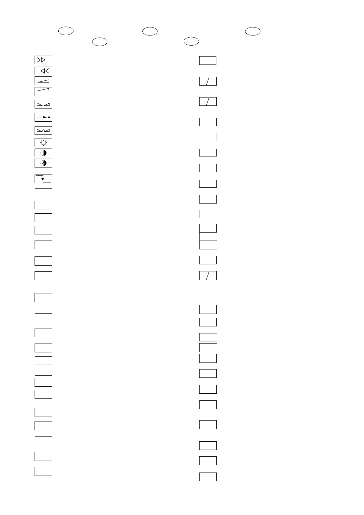
Schaltplansymbole
D
Simboli sullo schema
I
Circuit Diagram Symbols
GB
E
Simbolos en los esquemas
Symboles schéma
F
-
REF.
A-AM
ABK
AUDIO
AUDIO-L
AUDIO-R
AUDIO
MAC
AUDIO
L - MAC
AUDIO
R - MAC
Audio
Sub
AUDIO
TV
AUDIO
VCR
A-ZF 1
A-ZF 2
B
BB
BB
B
EXT
B
OSD
B
PIP
B/50
Feinabst. + / Fine tuning + / Réglage fine + / Sint. fine + / Sint. fina +
+
Feinabst. - / Fine tuning - / Réglage fine - / Sint. fine - / Sint. fina -
Lautstärke / Volume / Volume / Volume sonore / Volumen
Referenz Lautstärke / Volume ref. volt. / Tens. de réf. vol. sonore /
Tens di rif. volume / Tens. ref. volumen
Balance / Balance / Balance / Balanciam. / Balance
Suchlauf / Self seek / Recherche autom. / Sint. autom. / Sintonia
automatica
Farbton / Tint / Teinte / Tinta / Tinte
Helligkeit / Brightness / Luminosité / Luminosita / Brillo
Kontrast / Contrast / Contraste / Contrasto / Contraste
Farbkontrast / Colour contrast / Contraste des coleurs / Contrasto
colore / Contraste de color
Schutzschaltung / Protection circuit / Circuit de sécurité / Circuito di
protezione / Circuito de protección
Audio AM
(Burst Key): Burstaustastimpuls / Burst blanking pulse / Impulsion de
suppress. de burst / Imp. di soppress. del burst / Imp. supresion burst
Ton-Signal / Audio signal / Signal audio / Segnale audio / Señal audio
Ton-Signal links / Audio signal left / Signal audio gauche / Segnale
audio sinistra / Señal audio izquierda
Ton-Signal rechts / Audio signal right / Signal audio droit / Segnale
audio destra / Señal audio derecha
Tonsignal D2 Mac / Audio signal D2MAC / Signal audio D2MAC /
Segnale audio D2MAC / Señal de sonido D2MAC /
Tonsignal links D2 Mac / Audio signal left D2MAC / Signal audio
gauche D2MAC / Segnale audio sinistro D2MAC / Señal de sonido
izquirdo D2MAC
Tonsignal rechts D2 MAC / Audio signal right D2MAC / Signal audio
droit D2MAC / Segnale audio destro D2MAC / Señal de sonido
derecho D2MAC /
Audio Tieftöner / Audio sub woofer / Audio haut-parleur pour les
frequences basses / Audio toni bassi / Audio sonido bajo
Audio-Signal FS Gerät / Audio signal TV set / Signal audio
téléviseur / Segnale audio TV / Señal audio TV
Tonsignal VCR Gerät / Audio signal VCR unit / Signal audio
magnetoscope / Segnale audio VCR / Señal audio VCR
Audio ZF 1 / Audio IF 1 / Audio FI 1 / Audio FI 1 / Audio FI 1
Audio ZF 2 / Audio IF 2 / Audio FI 2 / Audio FI 2 / Audio FI 2
Blau-Signal / Blue signal / Signal bleu / Segnale blu / Señal azul
Rechner Stop I2C Bus frei / Computer Stop I2C Bus is free /
Microprocesseur stop I2C Bus disponible / Calcol. stop I2C Bus
libero / Stop micropr. disponible
Basisband / Baseband / Bande de base / Banda base / Banda base
Blau-Signal extern / Signal blue external /Signal bleu externe /
Segnale blu esterno / Señal azul externa
OSD-Einblendung blau / OSD blue / Eblouissement OSD bleu /
Visualizzazione OSD blu / Visualisacione OSD azul
Blau-Signal PIP / PIP Blue signal / Signal bleu PIP / Segnale blu
PIP / Señal azul PIP
Blau - Signal - 50Hz vert.,15625Hz hor. / Blue signal - 50Hz vert.,
15625Hz hor. / Signal bleu - 50Hz vert., 15625Hz hor. / Segnale bleu
- 50Hz vert., 15625Hz hor. / Señal azul - 50Hz vert., 15625Hz hor.
B/100
B-Y
50
B-Y
100
C
CENTER
CHIP
AD
CINCH
AUDIO L
CINCH
AUDIO R
CHROMA
CLK
CL 1
CL 2
CSY
CS
100
DATA
DL
ENA
ENABLE
FT
ENABLE
LED
ENABLE
TON
EURO-AV
AUDIO-L
EURO-AV
AUDIO-R
EURO-AV
VIDEO
F
FBAS
Blau-Signal -100Hz vert., 31250Hz hor. / Blue signal -100Hz vert.,
31250Hz hor. / Signal bleu -100Hz vert., 31250Hz hor. / Segnale blu
-100Hz vert., 31250Hz hor. / Señal azul -100Hz vert., 31250Hz hor.
B-Y -Signal - 50Hz vert., 15625Hz hor. / B-Y -Signal - 50Hz vert.,
15625Hz hor. / Signal B-Y - 50Hz vert., 15625Hz hor. / Segnale BY - 50Hz vert., 15625Hz hor. / Señal B-Y - 50Hz vert., 15625Hz hor.
B-Y -Signal - 100Hz vert., 31250Hz hor. / B-Y -Signal - 100Hz vert.,
31250Hz hor. / Signal B-Y - 100Hz vert., 31250Hz hor. / Segnale BY - 100Hz vert., 31250Hz hor. / Señal B-Y - 100Hz vert., 31250Hz hor.
Kanalwahl / Channel selection / Sélection de canaux / Selez.
canale / Seleccion canal
Mitttelpunkt-Lautsprecher / Center loudspeaker / Haut-parleur de
centre / Alto parlante punto centrale / Altavoz del centro
Chip Adresse / Chip adress / Chip direction / Indiri. del chip /
Direccion chip
Ton-Signal Cinch links / Audio signal cinch left / Signal audio cinch
gauche / Segnale audio cinch sinistra / Señal audio cinch izquierda
Ton-Signal Cinch rechts / Audio signal cinch right / Signal audio
cinch droit / Segnale audio cinch destra / Señal audio cinch derecha
Chroma Signal / Chroma signal / Signal dégree / Croma segnale /
Señal croma
Chroma S-VHS-Signal / Chroma S-VHS-Signal / Signal dégree de
S-VHS / Croma segnale S-VHS / Señal croma S-VHS
Clock
Composite Sync. Imp. für VT / Composite sync pulse for TT / Imp. de
sync. vidéo-composite pour TXT / Imp. hor. para Video Comp.
Kombiniertes Hor./vert. Sync. Signal 31250Hz/100Hz (Composite
Sync.) / Combined hor./vert. sync signal 31250Hz/100Hz (Composite Sync) / Signal synchr. hor./vert. combiné 31250Hz/100Hz
(Synchr. composité) / Segnale sincr. orizz./vert. 31250Hz/100Hz
(Sincr. Composito) / Señal combinada sincr. hor./vert. 31250/100Hz
(Sincr. compuesto)
Daten / Data / Données / Dati / Datos
Verzögerungsleitung / Delay line / Ligne à retard / Linea di ritardo /
Linea de retardo
Freigabe / Enable / Autorisation / Consenso / Habilitacion
Freigabe ZF / IF Enable / Validation FI / Consenso FI / Autorizacón FI
Freigabe FT / Finetuning enable / Autorisation Réglage fin / Abilitaz.
Sintonia fine / Habilitacion Sintoinia fina
Freigabe LED / LED enable / Autorisation LED / Abilitaz. LED /
Habilitacion LED
Freigabe Ton / Sound enable / Autorisation son / Abilitaz. audio /
Habilitacion sonido
Audio-Signal EURO-AV links / Audio signal EURO-AV left / Signal
audio EURO-AV gauche / Segnale audio EURO-AV sinistra / Señal
audio izquierda EURO-AV
Audio-Signal EURO-AV rechts / Signal audio EURO-AV right /
Signal audio EURO-AV droit / Segnale audio EURO-AV destra /
Señal audio derecha EURO-AV
Video-Signal EURO-AV / Video signal EURO-AV / Signal video
EURO-AV / Segnale video EURO-AV / Señal video EURO-AV
Farb-Signal / Chroma signal / Signal chroma / Segnale chroma /
Señal croma
FBAS-Signal / CCVS signal / Signal vidéo composite / Segnale video
composito / señal video compuesta
1 - 9

FBAS
CINCH
FBAS
MAC
FBAS
TON
FBAS
TXT
FBAS
TEXT
FBAS
SYNC.
FBAS
S-VHS
F
H
FRM
FT
F
U
F
V
G
G
OSD
G
PIP
G
EXT
G/50
G/100
GND - H
HA
HDR
HC
H
SYNC
HFB
HS
I2S CL
I2S TER
I2S IN
I2S WS
I BEAM
ICL
IR
IM
CLOCK
IM
IDENT
1 - 10
FBAS-Signal-Cinch Buchse / CCVS signal-cinch socket / FBASprise à cinch / FBAS-presa cinch / FBAS-cinch
FBAS-D2 MAC / D2MAC CCVS signal / Signal vidéo compositeD2MAC / FBAS-D2MAC / FBAS-D2MAC
Basisband / Baseband / Bande de base / Banda base / Banda base
FBAS-Videotext / CCVS videotext / Signal vidéo compositeTélétexte / FBAS-Televideo / FBAS-Teletexto
FBAS Sync. Signal / CCVS sync signal / Signal sync. vidéo col.
comp. / Segnal sincr. video col. comp. / Señal sincr. video
compuesta
FBAS Signal S-VHS / CCVS signal S-VHS / Signal vidéo col. comp. SVHS / Segnal video col. comp. S-VHS / Señal video compuesta S-VHS
Hochspg. / EHT voltage / Haute tens. / Alta tens. / MAT
Rahmensignal / Frame signal / Signal d'encadrement / Segnale
cornice / Señal de marco
Feinabstimmung / Fine tuning / Reglage fin / Sint. fine / Sint. fina
FU-Signal / FU-signal / Signal FU / Segnale FU / Senal FU
FV-Signal / FV-signal / Signal FV / Segnale FV / Senal FV
Grün-Signal / Green signal / Signal green external / Signal vert /
Segnale verde / Señal verde
OSD-Einblendung grün / OSD green / Eblouissement OSD vert /
Visualizzazione OSD verde / Visualisacione OSD verde
Grün-Signal PIP / Green signal PIP / Signal green PIP/ Signal vert
PIP / Segnale verde PIP / Señal verde PIP
Grün-Signal extern / Green signal vertical / Signal vert externe /
Segnale verde esterno / Señal verde externa
Grün-Signal - 50Hz vert.,15625Hz hor. / Green signal - 50Hz vert.,
15625Hz hor. / Signal vert - 50Hz vert., 15625Hz hor. / Segnale
verde - 50Hz vert., 15625Hz hor. / Señal verde -50Hz vert., 15625Hz hor.
Grün-Signal -100Hz vert., 31250Hz hor. / Green signal -100Hz vert.,
31250Hz hor. / Signal vert -100Hz vert., 31250Hz hor. / Segnale
verde -100Hz vert., 31250Hz hor. / Señal verde -100Hz vert.,
31250Hz hor.
Nullpunkt Heizung / Ground filament / Point neutre-Chauffage /
Punto zero-Filamento / Punto medio filamento
Horiz. Sync. Impuls / Horiz. Sync pulse / Impulsion synchro. horiz. /
Impulso sincro orizzontale / Impulso de sinc. horiz.
Horiz. Ansteuerimpuls / Horiz. drive pulse / Impulsion de commande
horiz. / Impulso comando orizzontale / Impulso de control horiz.
Horiz. Klemmimpuls / Horiz. clamp pulse / Impulsion de serrage
horiz. / Impulso comando orizzontale / Impulso de garras horiz.
Horizontaler Sync-Impuls / Horizontal Sync impuls / Sync impuls
horizontale / Sinc impulso orrizontale / Impulso sync horizontal
Horiz. Rückschlagimpuls / Horiz. flyback / Impulsion de retour
horiz. / Impulso rotorno orizzontale / Impulso de retroceso horiz.
Hor. Sync. Implus für VT / Hor. sync pulse for TT / Imp. de sync. hor. pour
TXT / Imp. sincr. orizz. per Televideo / Imp. hor. para Video Comp.
Digitale Datensignale / Digtital data signals / Signal donneé digital /
Segnali dati digitali / Señal datos digital
Strahlstrom / Current beam / Current rayon / Corrante del irradire /
Corriente de haz
I2C Bus -Clock
Infrarot-Signal / Signal infrared / Signal infra-rouge / Segnale
infrarosso / Señal infrarojo.
I2C Bus -Clock
I2C Bus -Kennung / I2C-Bus Identification / Identification I2C-Bus /
Ident. I2C-Bus, Identification I2C-Bus
IM
RESET
IR CLK
IR DATA
IR
VIDEO
KB
KH
AUDIO-L
KH
AUDIO-R
L
LED
M
MEGA
LOGIC
MODE
NIC CLK
NORM
OWA
P
P/C
PIP
P1
R
REMOTE
R
OSD
R
PIP
R
EXT
R-Y
50
R-Y
100
S
SB
SCL
SCL 100
I2C Bus -Reset
Infrarot Clock / Infrared clock / Signal I.R. horloge / Clock segnale
R.I. / Clock infrarojos
Infrarot Signal / Infrared signal / Signal I.R. / Segnale infrarosso /
Data infrarrojos
Infrarot Signal Video / Infrared signal video / Signal I.R. video /
Segnale infrarosso video / Data infrarrojos video
Keyboard
Tonsignal Kopfhörer links / Audio signal headphone left / Signal
audio gauche de casque / Segnale audio sinistra cuffia / Señal audio
izquierda auriculares
Tonsignal Kopfhörer rechts / Audio signal headphone right / Signal
audio droit de casque / Segnale audio sinistra cuffia / Señal audio
derecha auriculares
Lautstärke / Volume / Volume / Volume sonore / Volumen
Leuchtdiode / Light emitting diode / Diode lumineuse / Diodo
luminoso / Diodo luminescente
Speicher Taste / Memory button / Touche mémoire / Tasto di
memoria / Puls. memoria
Megalogic Daten / Megalogic data / Megalogic dates / Dati
Megalogic / Megalogic datas
Modus / Mode / Mode / Modo / Modo
NICAM Clock / Clock NICAM / Horloge NICAM / Clock NICAM /
Clock NICAM
Norm Taste / TV standard select button / touche de norme / Tasto
norma / Puls. de norma
Ost-West Ansteuerimpuls / East-west drive impuls / Impulsion de
commande Est-Ouest / Impulso comando Est-Ovest / Impulso de
control Este-Oeste
Programm / Program / Programme / Programma /Programa
Programm-Kanalwahl / Program channel selection / Progr. sélection
de canaux / Progr. selez.canale / Progr. selec. canal
Bild im Bild / Picture in picture / Image dans l'image / PIP / Imagen
en la imagen
Progr. Taste / Progr. button / Touche Progr. / Tasto Progr. / Puls.
Progr.
Rot-Signal / Red signal / Signal rouge / Segnale rosso / Señal rojo
Fernbedienung / Remote control / Telecommande / Telecomando /
Mando a distancia
OSD-Einblendung rot / OSD red / Eblouissement OSD rouge /
Visualizzazione OSD rosso / Visualisacione OSD rojo
Rot-Signal PIP / Red signal PIP / Signal rouge PIP / Segnale rosso
PIP / Señal rojo PIP
Rot-Signal extern / Signal red external / Signal rouge externe /
Segnale rosso esterno / Señal rojo externa
R-Y -Signal - 50Hz vert., 15625Hz hor. / R-Y -Signal - 50Hz vert.,
15625Hz hor. / Signal R-Y - 50Hz vert., 15625Hz hor. / Segnale RY - 50Hz vert., 15625Hz hor. / Señal R-Y - 50Hz vert., 15625Hz hor.
R-Y -Signal - 100Hz vert., 31250Hz hor. / R-Y -Signal - 100Hz vert.,
31250Hz hor. / Signal R-Y - 100Hz vert., 31250Hz hor. / Segnale
R-Y - 100Hz vert., 31250Hz hor. / Señal R-Y - 100Hz vert., 31250Hz hor.
Sonderkanal / Special channel / Canal special / Canale speciale /
Canal especial
Strahlstrombegrenzung / Beam current lim. / Lim. cour. de faisceau /
Lim. corr. di raggio / Corriente media de haz
I2C-Bus Clock
Schneller I2C-Bus Clock / I2C-Bus clock high speed / I2C-Bus grande
vitesse / I2C-Bus veloce / Clock del I2C-Bus de alta velocida

SDA
U
HI FI
MUTE
U
KH
MUTE
SHIFT
VIDEO
SHIFT
TEXT
SS
SSB
SSC
SSC
PIP
SSC
SSC
SUR-
ROUND
SYNC
SYNC.
BTX
SYNC.
VT
SW
TE
T1
T2
T T
U
FOC
U
U
U
SG
U
G 2
VA
VB
VCL
VDR
VG
VIDEO
VT DATA
VT SCL
VT SDA
I2C-Bus Daten / I2C-Bus data / I2C-Bus données / I2C-Bus dati /
I2C-Bus datos
Dynamische vert. Versch. 25Hz, aktiv bei Video u. Mix Betrieb /
Dynam. vert. shift 25Hz, active on video and mix operation / Decal
dynam. de l'image 25Hz, actif sur video et fonction. mixte / Spostam.
vert. dinam. 25Hz, attivo con video e. funzionam. misto / Desplaz.
dinamico vert. 25Hz, activo con video Y funciones mixtas
Dynamische vert. Versch. 25Hz, aktiv bei Standbild u. VT / Dyn. vert.
shift 25Hz, active on freeze-frame and Teletext / Decal dynam. de
l'image 25Hz, actif sur arret immage et Vidéotext (Antiope) / Spostam.
vert. dinam. 25Hz, attivo con fermo immag. e Televideo / Desplaz.
dinamico vert. 25Hz, activo con imagen parada Y Videotexto
Schutzschaltung / Protection circuit / Cablage protecteur / Pot. de
prot. / Circuito de proteccion
Spitzenstrahlstrombegrenzung / Peak beam current limiting / Lim.
de faisceau crete / Lim. corr. catod. di pico / Corrente pico de haz
Supersandcastle
Supersandcastle PIP
Supersandcastle 100Hz vert., 31250Hz hor.
100
Supersandcastle 50Hz vert., 15625Hz hor.
50
Surround
Sync.-Signal / Sync.-Signal / Signal sync / Segnale sync. / Señal de sync.
Sync. BTX / Viewdata Sync / Sync. Télétext / Sincr. Videotel / Sincr.
Videotexto
Sync. VT / Sync. Teletext / Sync Vidéotexte / Sincr. Televideo / Sincr.
Videotexto
Schwarzwert / Black level / Niveau du noir / Livello del nero / Nivel de negro
TEXT-Freigabe / TEXT enable / Autorisation TEXTE / Abilitaz.
TELEVIDEO / Habilatation TEXTE
Bei Zweiton, Ton 1 / On two channel sound, sound 1 / Pour double
son, son 1 / In bicanale, audio 1 / En dual, sonido 1
Bei Zweiton, Ton 2 / On two channel sound, sound 2 / Pour double
son, son 2 / In bicanale, audio 2 / En dual, sonido 2
Tieftöner / Woofer / Haut-parleur pour les frequences basses / Toni
bassi / Sonido bajo
Fokusspg. / Focussing volt. / Tens. de focalis. / Tens di focalizz. /
Tens focalizacion
Spg. Gitter G 1 / Volt. grid G1 / Tens grille G 1 / Tens. griglia G1 / Tens.
G1
rejillas G 1
H
Hochspannung / High voltage / Haute tension / EAT / Alte tension
Schirmgitter Spg. / Screen-grid volt. / Tens. de grille - écran / Tens.di
griglia schermo / Tens. de rejilla
Vertikaler Ansteuerimpuls / Vert. drive pulse / Impulsion de commande
verticale / Impulso di comando verticale / Impulso de control vertical
VCR - Clock
Freigabe Anzeigebaustein / Display enable / Autorisation pour module
indicateur / Modulo indicazione / Habilitacion modulo indicacion
Vert. Gegenkopplung / Vert. feedback / Contre-reaction verticale /
Controreazione vert. / Aliment. neg. vert.
Video Signal / Video signal / Signal vidéo / Segnale video / Señal video
Videotext Daten / Teletext data / Données Teletexte / Linea dati
Televideo / Data Teletexto
Videotext Clock / Teletext clock / Signal horloge Vidéotext / Clock
Televideo / Clock Teletexto
I2C Bus: VT Daten / Teletext data / Données Vidéotext / Dati
Televideo / Data Teletexto
SYNC
Y
Y
U
U
U
U
U
U
U
U
U
U
U
U
U
U
U
U
U
U
U
U
Vertikaler Sync-Impuls / Vertical Sync impuls / Sync impuls vertical
V
/ Sinc impulso vertical / Impulso sync vertical
Y-Signal / Y Signal / Signal Y /Segnale Y / Señal Y
Y
Y -Signal - 50Hz vert., 15625Hz hor. / Y -Signal - 50Hz vert., 15625Hz
50
hor. / Signal Y - 50Hz vert., 15625Hz hor. / Segnale
Y - 50Hz vert., 15625Hz hor. / Señal Y - 50Hz vert., 15625Hz hor.
Y - Signal - 100Hz vert., 31250Hz hor. / Y -Signal - 100Hz vert.,
100
31250Hz hor. / Signal Y - 100Hz vert., 31250Hz hor. / Segnale
Y - 100Hz vert., 31250Hz hor. / Señal Y - 100Hz vert., 31250Hz hor
ZF
Zwischenfrequenz / IF / FI / FI / FI
Schaltspg. AFC / AFC switching volt. / Tens. de commut. AFC/ Tens.
AFC
di commut. AFC / Tens. conmut. CAF
Schaltspg. AV / Switching volt. AV / Tens. de commut. AV / Tens. di
AV
commut. AV / Tens. conmut. AV
Schaltspg. Band 1 / Switching volt. band 1 / Tens. de commut.
B1
bande 1 / Tens. di commut. banda 1 / Tens. conmut. de banda 1
Schaltspg. Band 3/ / Switching volt. band 3 / Tens. de commut.
B2
bande 3 / Tens. di commut. banda 3 / Tens. conmut. de banda 3
Schaltspg. Bildamplitude / Switching voltage vertical amplitude /
BA
Tension de coupure amplitude dìmage / Tensione di commutaz.
ampiezza d'imagine / Tension de conm. amplitude de imagen di
commut. PAL / Tens. conmut. PAL
Schaltspg. BTX / Switching volt. BTX (Viewdata) / Tens. commut.
BTX
Télétext / Tens. commut. VIDEOTEL / Tens. conmut. Teletexto
Schaltspg. Camera Wiederg. über Camera-AV Eingang / Switching
C-AV
volt. cam. playback via Camera-AV input / Tens de commut pour lec.
de camera par l'entree Camera-AV / Tens.de commut. in riproduz.
CAM
AV
camera tramite ingresso Camera-AV / Tens. de serv. reprod. camera
a traves de la entrada Camera-AV
Schaltspg. Datenbetr. / Switching volt. data mode / Tens. de com-
DATA
mut. fonct. données / Tens. di commut. dati / Tens conmut. datos
Schaltspg. U Data extern / Switching volt Data ext. / Tension de
DATA
EXT
commutation U Data externe / Tens. di commutazione U-Data
esterno / Tensión de conmutatón externa U
Schaltspg. für Bildschirm-Einblendung / Switching volt. for On
DATA
OSD
Screen Display / Tens. commut. pour eblouissement On Screen
Display / Tens. commut. per di visualizzazione On Screen Display /
Tens. conmut. para On Screen Display
Schaltspg. Deemphasis / Switching volt. deemphasis / Tens. com-
DEEM
mut. desaccent. / Tens. commut. deenfasi / Tens. conmut. deenfasis
Schaltspg. Dolby-Surround / Switching volt. Dolby-Surround / Tens.
commut. Dolby-Surround / Tens. commut. di Dolby-Surround / Tens.
DS
de conmut. Dolby-Surround
Schaltspg. EURO-AV / Switching volt. EURO-AV / Tens. de commut.
EURO-
AV
EURO-AV / Tens. di commut. EURO-AV / Tens. conmut. EURO-AV
Schaltspg. EURO-AV-Cinch-Buchse / Switching volt. EURO-AV-
EU-AV
CINCH
Cinch socket / Tens. commut. prisa Scart - Cinch / Tens. commut.
presa Scart -Cinch / Tens. conm. EURO-AV - Cinch
Schaltspannung für Video-Ausgang EURO-AV Buchse / Switch.
FBAS
voltage for video output EURO-AV socket / Tension de commut.
pour sortie vidéo EURO-AV / Tension commut. per presa d'uscita
video EURO-AV / Tension de conmut. para salida EURO-AV
Schaltspg. HIFI / Switching voltage HIFI / Tens. de commut. HIFI /
HIFI
Tens di commut. HIFI / Tens. conmut. HIFI
Stummschaltung HiFi / Muting volt. HiFi / Commutation de silence
HiFi / Silenzametno HiFi / Muting HiFi
Schaltspg. HUB / Switching volt. deviation / Tens. commut.
HUB
déviation / Tens. commut. deviazione / Tens. conmut. deviacion
Schaltspg. Signalkennung AV 3 / Switching volt. signal identification
IDENT
AV 3 / Tens de commut.identification de signal AV3 / Tens. commut.
identificazione segnale / Tens. conmut. identifi. segñal AV3
Stummschaltung Kopfhörer / Muting volt. headphone / Commutation
de silence casque / Silenzamento cuffia / Muting auriculares
Gleichspannung für SAT-Basissignal / DC for SAT basic signal /
KLEMM
Tens. continue pour SAT base signal / Tens continua per segnale
SAT base / Tens. continua para segñal SAT base
1 - 11

U KOIN
50/60Hz
KOIN
U
VQ
U
LED
U
Leucht-.
punkt
U
LNC
OFF
U
MAC
U
MUTE
U
NF 1
U
NF 2
U
NIC
U
NORM
U
PAL
U
POL.
U
POWER
OFF
U
PV
U
RESET
U
RGB
U
SCHUTZ
U
SEC
STAND
U
BY
U
S-VHS
U TON
1/2
U
UHF
U
VHF
U
VQ
U
WISCH
Schaltspg. Koinz. / Switching volt. coinc. / Tens de commut. coinc. /
Tens di commut. coinc. / Tens. conmut. coinc.
Schaltspg. Koinz. mit Videoquelle verknüpft / Coinc. switching volt.
linked with video source / Signal de coincid. combiné avec source
video / Tens. di commut. a coinc. combinata con sorg video segñal
de coincidencia combinada con video
Schaltspg. LED / Switching volt. LED / Tens de commut. LED / Tens.
commut. LED / Conmut. LED
Schaltspg. Leuchtpunktunterdrückung / Switching volt. beam spot
suppression / Tens. de commut. suppress. du spot lumineux / Tens.
soppr. punto luminoso / Tens. de conmut. filtro supresor del punto
luz
Schaltspg. LNC "Aus" / Switching volt. LNC "OFF" / Tens. de
commut. LNC "OFF" / Tensione di commut. "Spento" LNC / Tension
LNC "OFF"
Schaltspg. D2MAC / Switching volt. D2MAC / Tension de
commutation D2MAC / Tens. di commutazione D2MAC / Tensión de
conmutación D2MAC
Stummschaltung / Muting / Silencieux / Silenziamento /Muting
Schaltspg. NF 1 / Switching volt. AF 1 / Tension commut. BF 1 / Tens.
commut BF 1 / Tens. conm. BF 1
Schaltspg. NF 2 / Switching volt. AF 2 / Tension commut. BF 2 /
Tens. commut BF 2 / Tens. conm. BF 2
Schaltspg. NICAM / Switching volt. NICAM / Tens. de commut.
NICAM / Tens. commut. NICAM / Tens. de conmut. NICAM
Schaltspg. Norm / Switching volt. Norm / Tens. de commut.
standard / Tens. di commut. Norma / Tens. conmut. Norma
Schaltspg. PAL / Switching volt. PAL / Tens. de commut. PAL / Tens.
di commut. PAL / Tens conmut. PAL
Schaltspg. Polarität / Switching volt. polarity / Tension commut.
polarite / Tens. commut. polarita / Tens. conmut polarizacion
Schaltspg. Ökoschalter / Switching volt. eco switch / Tens. de
commut. interr. eco. / Tens. commut. interr. ecologico / Tens.
conmut. interr. ecol.
Schaltspg. Panorama View / Switching volt. Panorama View / Tens.
de commut. Panorama View / Tens. commut. Panorama View /
Tens. conmut. Panorama View
Schaltspg. Reset / Switching volt. Reset / Tens. commut. Reset /
Tens. commut. Reset / Tens. conmut. Reset
Schaltspg. RGB1 - RGB2 / Switching volt. RGB1 - RGB2 / Tens. de
commut. RGB1 - RGB2 / Tens. di commut. RGB1 - RGB2 / Tens.
conmut. RGB1 - RGB2
Schaltspg.-Schutzfunktion / Switching volt.-protective func. / Tens
de commut.-sécurité / Tens. di commut.-funz di protez. / Tens.
conmut.-proteccion
Schaltspg. SECAM / Switching volt. SECAM / Tens. de commut.
SECAM / Tens. di commut. SECAM / Tens. conm. SECAM
Schaltspg. Standby / Switching volt. Standby / Tens. commut.
Veille / Tens. commut. Standby / Tens. conmut. Standby
Schaltspg. S-VHS / Switching volt. S-VHS / Tens.de commut.
S-VHS / Tens. de commut. S-VHS / Tens. de conmut. S-VHS
Schaltspg. Ton 1-2 / Switching volt. sound 1-2 / Tens. commut. audio
1-2 / Tens. commut. son 1-2 / Tens. conmut. son 1-2
Schaltspg. UHF / UHF switching volt. / Tens. de commut. UHF / Tens
di commut. UHF / Tens. conmut. UHF
Schaltspg. VHF / VHF switching volt. / Tens. de commut. VHF / Tens
di commut. VHF / Tens. conmut. VHF
Schaltspg. Videoquelle / Switching volt. video source / Tens. de
commut. source video / Tens. di commut. sorg. video / Tens conmut.
video
Schaltspg. Wischerkontakt / Schwitching voltage temp. contact /
Tens. de commut. contact fugitif / Tens. commut. contatto temporaneo / Contacto supresor tens. de conmut.
U
W/N
U
I / III
U
14V
U
22kHz
0/3/6/9V
U
4.5MHz
U
50/60
HZ
U
AFC
U
AFC
SAT
U
AGC
U
RE
U
TUN.
U
HOR.
HOR.2FH
VERT.
VERT.
VER. 2FV
VERT.
VERT.
VERT.100
VERT.100
REF.
PULSE
O/W
Schaltspg. ZF breit - schmal / IF switching volt. wide - narrow / Tens.
commut. FI large - etroit / Tens. commut. FI larga - stretta / Tens. FI
ancho - estrecho
Schaltspg. Bandwahl / Band sel. switching volt. / Tens. de commut.
select. bande / Tens. di commut. selez. banda / Tens. conmut. selec.
banda
14V Schaltspg. / 14V switching volt. / Tens. commut. 14V / Tens.
commut. 14V / Tens. de conm. 14V
22kHz Schaltspg. / 22kHz switching volt. / Tens. commut. 22kHz /
Tens. commut. 22kHz / Tens. de conm. 22kHz
0/3/6/9V Schaltspg. / 0/3/6/9V switching volt. / Tens. commut.
0/3/6/9V / Tens. commut. 0/3/6/9V / Tens. de conm. 0/3/6/9V
Schaltspg. 4,5MHz / Switching volt. 4.5MHz / Tens. de commut.
4,5MHz / Tens. di commut. 4,5MHz / Tens conmut. 4,5MHz
Schaltspg. 50-60Hz / Switching volt. 50-60Hz / tens. de commut.
50-60Hz / Tens. di commut. 50-60Hz / Tens. conmut. 50-60Hz
Regelspg. AFC / AFC contr. volt. / Tens. de regul. AFC / Tens. di
contr. AFC / Tens. regul. CAF
Regelspg. AFC Satellitentuner / AFC contr. volt. SAT tuner / Tens.
de regul. AFC tuner SAT / Tens. di contr. AFC Tuner SAT / Tens.
regul. CAF Tuner SAT
Feldstärkeabhängige Spg. / Fieldstrength-depent volt. / Contr. automatique de gain / Tens. dipent. intens. campo / Contr. autom. de gain
tens. CAG
Regelspg. / Contr. volt. / Tens. de regul. / Tens. di contr. / Tens regul.
Abstimmspg. Tuner / Tuning volt. tuner / Tens. d'accord tuner / Tens.
di sintonia tuner / Tens. sintonia tuner
Regelspg. Verzög. / Delayed contr. volt. / Tens. de regul. retardee/
Tens. regul. retardada
Horizontale Ansteuerung / Horiz. drive / Synchr. lignes / Pilotaggio
orizz. / Exitación horiz.
31250Hz Ansteuerimp. für Zeilenendstufe / 31250Hz Triggering
pulse for horiz. output / 31250Hz commande pour l'étage final
lignes / Imp. Pilotaggio di 31250Hz per stadio finale di riga / Impulso
de exitación 31250Hz para paso final de lineas
Vert. Parabel / Vert. parabolic signal / Signal parabolique vert. /
Segnale parab. vert. / Senal parabolica vert.
Vert. Tastimpuls / Vert. Gating pulse / Imp. trame / Imp. a cadenza
vert. / Imp. cuadro
Vert. Tastimpuls 100Hz / Vert. Gating pulse 100Hz / Imp. trame
100Hz / Imp. a cadenza vert. 100Hz / Imp. cuadro 100Hz
Vert. Sägezahn / Vert. saw tooth / Signal dent de scie / Dente di sega
vert. / Dientede sierra vert.
Vert. Tastimpuls / Vert. Gating pulse / Imp. trame / Imp. a cadenza
vert. / Imp. cuadro
Vert Sägezahn 100Hz / Vert saw tooth 100Hz / Signal dent de scie
100Hz / Dente di sega vert. 100Hz / Dientede sierra vert. 100Hz
Vert. Parabel 100Hz / Vert. parabolic 100Hz signal / Signal parabolique 100Hz vert. / Segnale parab. vert. 100Hz / Senal parabolica
vert. 100Hz
Tastimpuls / Gating pulse / Impuls de declenchement / Impulso a
cadenza / Imp. puerta
Ref. Impuls hor. / Reference impulse hor. / Imp. de refer.hor. / Imp.
di rifer. hor. / Imp. refer. horiz.
Klemmung Ein-Aus / Clamping On-Off / Clampage Marche-Arrêt /
Clamping Ins.-Disins. / Clamping Enc.-Apag.
Pulse für Polarotor / Pulses for Polar-Rotor / Impulsions Rotor de
Polariastion / Impulsi per Rotore Polarizzazione / Impulsos dara
Polarrotor
O-W Amplitude / E-W amplitude / Amplitude E-O / Ampiezza E-O /
Amplitud E-O
1 - 12
Service- und Sonderfunktionen
1. Einschaltfunktionen
1.1 ATS-Reset (Automatic Tuning System)
Netzschalter "EIN" mit gedrückter Fernbedientaste Ƿ –> Sprachaus-
wahl –> OK.
Das Automatische Sendersuchsystem stoppt bei jedem empfangswürdigen Sender (AFC und Koinzidenz) und speichert automatisch die
entsprechenden Senderdaten mit dem jeweiligen Standard (die Speicherung findet unmittelbar im NVM statt). Danach wird der Suchlauf
fortgesetzt.
Tastendruck "TXT" bricht den ATS-Lauf ab.
1.2 Mittelwerte / Notdatensatz laden (ROM-Daten)
Fernbedienbedientaste "P-" gedrückt halten und das Gerät mit dem
Netzschalter einschalten. Dadurch wird z. B. nach Austausch des
IC82005 (NVM) das Gerät mit dem Notdatensatz gestartet.
Mit diesem Vorgang werden die Grund-Daten aus dem ROM des
Prozessors IC81050 in den NVM IC82005 kopiert:
IC82005: (gerätespezifische Daten, über das Dialog Center einstellbar)
- Farb- und Ton-Normen
- Decodereinstellungen
- Zwangs-Mono
- Umkehrpunkt
- Sendername on/off
- OSD Position
- Blue Screen on/off, Black Screen on/off
- ATS-Reset
- Hotel-Mode on/off
- AGC und AFC
- Öko-Schalter
- Bildröhrentype
- Analogwerte (Lautstärke, Helligkeit usw.)
- Bildschärfe
- Overscan
- Security on/off
- Geometrieabgleich
- Programmdaten (Kanal- Feinabstimmung, Senderkennung)
Danach über das Dialog Center die persönlichen Werte, Bildgeometrie
eingeben.
1.3 Programmsperre (Kindersicherung) dauerhaft aufheben
Die Zahl 7038 hebt die Sperre dauerhaft auf.
2. Sonderfunktionen im Dialog Center
2.1 Einschalten mit Programm "1" oder "AV"
Mit Taste "Ǻ" die Dialogzeile "TV einsch. mit" über "DIALOG CENTER"
–> "SONDERFUNKTIONEN" aufrufen. In Stellung "AV1" erscheint
beim Einschalten das AV-Bild.
2.2 "Bild-/Ton-Skala" ein oder aus für alle Programme
Mit Taste "Ǻ" die Dialogzeile "Bild-/Toneinst." über "DIALOG CENTER"
–> "SONDERFUNKTIONEN" aufrufen. In Stellung "aus" erscheinen
keine Balkenanzeigen für die Analogwerte auf dem Bildschirm.
2.3 Automatische Lautstärkeregelung (optionell)
Mit Taste "Ǻ" die Dialogzeile "Autom. Lautst." über "DIALOG CENTER"
–> "SONDERFUNKTIONEN" aufrufen. In Stellung "ein" wird bei
großen Senderhüben die Lautstärke automatisch an den normalen
Hub angepasst.
2.4 Programmplatzbezogene Decoder-Einstellung
Mit Taste "Ǻ" die Dialogzeile "Decoder Pxx" über "DIALOG CENTER"
–> "SONDERFUNKTIONEN" aufrufen. Mit den Tasten ǷǸ können
Sie programmplatzbezogen für verschlüsselte Sendungen einen analogen oder digitalen Decoder auf interne oder externe Umschaltung
stellen (siehe 5.2).
2.5 Öko-Netzschalter aktivieren bzw. deaktivieren (optionell)
Mit Taste "Ǻ" die Dialogzeile "Öko-Netzschalt." über "DIALOG CEN-
TER" –> "SONDERFUNKTIONEN" aufrufen. Mit den Tasten ǷǸ
"1h…3h" stellen.
Das Gerät schaltet sich nach der eingestellten Zeit, oder durch
zweimaligen Tastendruck der Taste Ǽ aus dem Standby-Betrieb
komplett ab.
In Stellung "aus" wird diese Funktion nicht genutzt.
3. Bild-Einstellungen
Grundeinstellung
Mit der roten Taste (Auge) das Bild-Menü aufrufen. Über die Menüführung ist die Regulierung von Kontrast, Bildschärfe und Tint (nur bei
NTSC-Quellen) möglich.
Die Analogwerte für Kontrast, Bildschärfe und Tint werden beim
Verlassen des Menüs automatisch gespeichert.
4. Ton-Einstellungen
4.1 Tonumschaltung
Mit der blauen Taste (Ohr) das Ton-Menü aufrufen. Je nach SenderNorm sind für die Tonumschaltung verschiedene Einstellungen anwählbar:
- "Mono": bei reinen Mono-Sendungen
- "Mono A / Mono B": bei 2-Ton-Sendungen
- "Stereo / Mono": bei schlechtem Stereo-Ton kann auf Mono geschaltet werden
- "Nicam / FM"
- "Nicam A / Nicam B / FM"
- "Nicam Stereo / FM"
Die Werte für Zwangs-Mono, Balance, Bässe, Höhen und ähnliches
werden beim Verlassen des Menüs automatisch gespeichert.
4.2 Kopfhörer-Tonumschaltung
Mit der blauen Taste das Ton-Menü aufrufen. Je nach Sender-Norm
sind für den Kopfhörer verschiedene Einstellungen anwählbar:
- "Mono A / B", unabhängig von den Lautsprechern
- "Nicam A / Nicam B / FM", unabhängig von den Lautsprechern
Bei allen anderen Einstellungen ist der Kopfhörerton mit dem
Lautsprecherton fest gekoppelt.
5. Offene Service-Einstellungen
5.1 Maximale Programmnummer (Umkehrpunkt):
Programmnummer aufrufen, ab der die Programmplätze gesperrt
werden sollen. Mit Taste "Ǻ" die Dialogzeile "MANUELLE ABSTIMMUNG" über das "DIALOG CENTER" aufrufen. Über die Menüführung
in der Dialogzeile Band "00" einstellen. Mit "OK" bestätigen und Menü
beenden. Danach können im Programm-Mode mit den Tasten "P+/P-"
die nachfolgenden Programme nicht mehr fortgeschaltet werden.
5.2 Decoder P1…79
Mit Taste "Ǻ" die Dialogzeile "Decoder (P1-79)" über "DIALOG
CENTER" –> "SERVICE" aufrufen. Mit den Tasten ǷǸ können Sie für
die Programme 1…79 bei verschlüsselten Sendungen einen analogen
oder digitalen Decoder auf interne oder externe Umschaltung stellen.
Einstellungen des Decoders: "manuell", "aus", "ON1", "ON2", "ON3".
In Stellung "manuell" kann die Decoderumschaltung für die einzelnen
Programme auf unterschiedlicher Eingabe, wie "aus" oder "ON" stehen (siehe 2.4).
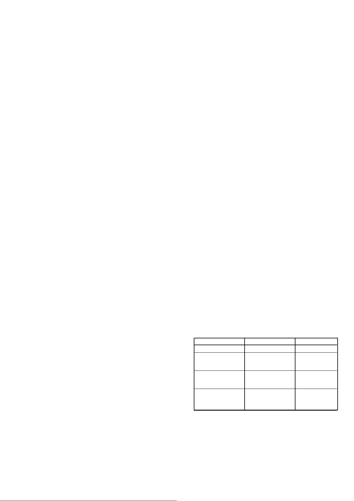
Bedeutung der Decoderstellungen:
Ton Bild
Decoder "aus" intern intern
Decoder "ON1"
Ton autom. extern Analog extern
intern Nicam-Ton
Decoder "ON2"
alle Töne extern Analog extern
extern Nicam-Ton
Decoder "ON3"
alle Töne intern Analog extern
intern Nicam-Ton
Die unterschiedlichen Einstellmöglichkeiten der Decoderfunktion stellen immer den richtigen Signalweg für das Audiosignal sicher.
1 - 13

Die drei möglichen Scramble-Verfahren:
Betriebsart:
Bild Ton Menü-Anzeige
1. Bild Analogton verschlüsselt Analog ext. bzw. ON1
verschlüsselt Nicamton unverschlüsselt Nicam intern
2. Bild Analogton verschlüsselt Analog ext. bzw. ON2
verschlüsselt Nicamton verschlüsselt Nicam intern
3. Bild Analogton unverschlüsselt Analog int. bzw. ON3
verschlüsselt Nicamton unverschlüsselt Nicam intern
Das Verfahren 1 ist für Canal + Betrieb.
Das Verfahren 2 und 3 wird z. B. in England verwendet.
Bildsignalweg
Da das Bild generell verschlüsselt ist, muss nur die Decoder-Schaltspannung für die Videoumschaltung angelegt werden.
Audiosignalweg
Fall 1:
Decoder nicht stereotauglich, deswegen Nicamton unverschlüsselt.
Der Decoder schaltet den Audioweg in Abhängigkeit des NicamDecoders zwischen intern und extern um.
Fall 2:
Decoder stereotauglich für verschlüsselten Analog- und Nicamton.
Deswegen wird auf Externbetrieb umgeschaltet (Regelfall).
Fall 3:
Ton wird generell nur intern verbunden (keine Beschaltung am
Audiozweig der EURO-AV-Buchse).
5.3 Farb-Zwangsumschaltung
Mit Taste "Ǻ" die Dialogzeile "Farbe" über "DIALOG CENTER" –>
"SERVICE" aufrufen. Mit den Tasten ǷǸ können Sie in schlechter
Empfangslage programmplatzbezogen die automatische Farbumschaltung zwangsweise auf "PAL", "SECAM" oder "NTSC" einstellen.
5.4 Blauen Bildschirmhintergrund abschalten
Mit Taste "Ǻ" die Dialogzeile "Blauer Bildschirm" über "DIALOG
CENTER" –> "SERVICE" aufrufen. In Stellung "aus" ist der blaue
Hintergrund (z.B. bei fehlendem Antennensignal) abgeschaltet.
5.5 Schwarzer Bildschirm bei der Programmumschaltung
Mit Taste "Ǻ" die Dialogzeile "Schwarz. Bildschirm" über "DIALOG
CENTER" –> "SERVICE" aufrufen. In Stellung "ein" wird der Bildschirm bei Programmwechsel dunkelgeschaltet.
5.6 Sendername aus- bzw. einblenden
Die Kennung wird über VT bzw. VPS ausgelesen.
Mit Taste "Ǻ" die Dialogzeile "Sendername" über "DIALOG CENTER"
–> "SERVICE" aufrufen. In Stellung "aus" können Sie die kurzzeitige
Einblendung des Sendernamens bei der Programmumschaltung unterdrücken.
5.7 Gruppenlaufzeit / Ländernormen einstellen
Mit Taste "Ǻ" die Dialogzeile "B/G FM 5,5 NIC" über "DIALOG CENTER"
–> "SERVICE" aufrufen. Je nach Empfangsort gewünschte Norm
einstellen. S/SF/N = linear, B/DK/E = entzerrt.
Bei Ländern mit Mischbetrieb (z.B. Dänemark) muss diese Einstellung
im Dialogmenü "Manuelle Abstimmung" –> "Standard" vorgenommen
werden.
6. Service-Einstellungen für den Fachhandel
6.1 Service Menü
Mit Taste "Ǻ" das Service Menü über "DIALOG CENTER" –> "SERVICE"
–> Service Code aufrufen.
Nach Eingabe der Codezahl "8500" kann der Fachhändler den Geräteabgleich laut Menüführung durchführen für:
- Geometrie
- Weißabgleich
- AGC
- AFC
- Tube
- Cut-off align
- Over-scan
Abgleich: Seite 2-1
6.2 OSD-Lage
Mit Taste "Ǻ" die Dialogzeile "OSD" über "DIALOG CENTER" –>
"SERVICE" –> Service Code "8500" aufrufen.
Mit den Tasten ǷǸ können Sie die horizontale, oder vertikale Lage
des Einblend-Menüs verschieben und mit "with mem." sichern.
6.3 Hotel-Mode
6.3.1 Hotel-Mode aktivieren
Mit Taste "Ǻ" die Dialogzeile "Hotel" über "DIALOG CENTER"
–> "SERVICE" –> Service Code "8500" aufrufen.
Bei aktiviertem "Hotel-Mode" ist:
- der Aufruf des "DIALOG CENTER" mit der Taste "Ǻ" nicht mehr
möglich.
- die zuletzt eingestellte Lautstärke wird als maximale Lautstärke
gespeichert.
6.3.2 Hotel-Mode ausschalten
Taste "Ǻ" der Fernbedienung gedrückt halten und das Gerät mit dem
Netzschalter einschalten. Im Menü "SERVICE" Hotel-Mode wieder
ausschalten.
6.4 Schutzschaltung deaktivieren
Taste "Ǻ" der Fernbedienung gedrückt halten und das Gerät mit dem
Netzschalter einschalten. Solange das Service Menü angezeigt wird,
wird die Schutzschaltung des Gerätes am Videoprozessor IC34015-(50)
nicht ausgewertet.
6.5 Softwareeinstellung
Mit Taste "Ǻ" die Dialogzeile "OSD vertical" über "DIALOG CENTER"
–> "SERVICE" –> Service Code "8500" aufrufen.
Mit den Tasten "AUX" –> "OK" die Software für Toshiba (Menüfarbe
rot) einstellen und mit "with mem." sichern.
7. Einstellung der Analogwerte
Maximalwert Optimalwert
Helligkeit 63 32
Farbkontrast
(TDA 8843-N1) 63 34
(TDA 8843 / 8844-N2) 63 25
SW-Kontrast 63 48
Lautstärke 63 27
Kopfhörer. Lautst. 63 50
Tint 63 32
Bässe 25 19
Höhen 25 16
Bildschärfe 5 2
Automatische Speicherung der Analogwerte:
Nach ca. 8 Sekunden,
nach Schalten in Standby,
nach Wechsel von TV zu AV,
nach Wechsel der einzelnen AV-Stellungen.
Nach Speicherung der Lautstärke erscheint beim Einschalten des
Gerätes der Lautstärkebalken für ca. 10 Sekunden.
Mit "AUX" –> "OK" können Sie die Optimalwerte für die Ton- und
Bildeinstellungen wiederherstellen.
Die Optimalwerte werden aus dem EEPROM IC82005 geladen.
8. Audio-/Video-Anschlüsse
Überspielmöglichkeiten:
AV 1 –> AV 2 (EURO-AV1 –> EURO-AV2 mit 2 EURO-AV-
Buchsen)
AV 2 –> AV 1 (EURO-AV2 –> EURO-AV1 mit 2 EURO-AV-
Buchsen)
AV 3 –> AV 1, AV2 (Camera –> EURO-AV1,2 mit 2 EURO-AV-
Buchsen)
AV 2 –> AV 1 (Camera –> EURO-AV mit 1 EURO-AV-Buchse)
Die Überspielmöglichkeit wird durch Anwahl Taste "0/AV" der Quelle
automatisch aktiviert.
1 - 14

Überspielfunktion
AV-Programmplatz mit der Taste "0 /AV" auswählen und mit den
Tasten "AUX" –> Taste "0/AV" die Copier-Funktion aktivieren (Anzeige "kopieren ein"). Während der Überspielung kann auf ein anderes
Programm umgeschaltet werden. Wiederholung der Tastenfolge
deaktiviert die Copier-Funktion (Anzeige "kopieren aus").
Hinweise:
- Sind bei AV-Anwahl schon alle Videowege belegt, z.B. weil Copy
aktiv ist, wird dies erkannt und auf die nächste technisch mögliche
AV-Stellung geschaltet.
- Bei Ländereinstellung Italien hat eine AV-RGB-Einspeisung mit
Austastsignal (Pin 16) Vorrang.
- Bei allen AV-Stellungen erscheint kein blauer Bildschirm.
AV-Buchsenbeschaltung
Buchse Eingang Ausgang Schaltsignal
AV1 RGB - 6/12V (Schaltspg.)
+1V (Fastblanking)-Auswertung
FBAS FBAS 6/12V
SBAS (Y/C) FBAS 6/12V
(gewandelt)
AV2 RGB - 6/12V + 1V Auswertung
FBAS FBAS 6/12V
SBAS (Y/C) FBAS 6/12V
(gewandelt)
AV3 FBAS - 5V selbst erzeugt aus Sync.
Camera
9. Bildformat-Umschaltung
Im AV-Betrieb kann mit der Fernbedientaste " " das Bildformat in
Abhängigkeit der Bildschirmgrößen umgeschaltet werden.
Formatumschaltung 4:3 und 16:9 in AV und Programmplatz mit Peribit.
Als Indikator dient die an Pin 8 der AV 1- und AV 2-Buchse anliegende
Schaltspannung.
- 4:3-Format 12V
- 16:9 Format 6V
Für 16:9 Camcorder-Wiedergabe nötig, um die vertikale Dehnung zu
kompensieren, da diese keine 16:9 Schaltspannung liefern.
Service and Special Functions
1. Switching-on Options
1.1 ATS Reset (Automatic Tuning System)
Press the power "ON" button while pressing button Ƿ on the Remote
Control –> LANGUAGE SELECTION –> OK.
The ATS system stops at every station of acceptable reception quality
(AFC and coincidence) and stores the station data and the respective
standard automatically (data is stored immediately in the NVM). The
system then continues searching.
Pressing the "TXT" button stops the ATS function.
1.2 Loading the Average Values / Emergency Data Set (ROM Data)
Press and hold the "P-" button on the Remote Control and switch on
with the mains button. After replacement of IC82005 (NVM) for
example, the TV set is started with the emergency data set.
In doing so, the basic data is read out from the ROM of processor
IC81050 and loaded into the NVM IC82005:
IC82005: (data specific to the TV can be set via the Dialog Center):
- chroma and audio standards
- decoder settings
- forced mono
- reversing point
- station ident on/off
- OSD position
- blue screen on/off, black screen on/off
- ATS reset
- Hotel Mode on/off
- AGC and AFC
- economy switch
- type of picture tube
- analog values (volume, brightness etc.)
- picture sharpness
- overscan
- security on/off
- geometry adjustment
- programme data (channel finetuning, station ident)
Subsequently enter your personal values, picture geometry via the
Dialog Center.
1.3 Cancelling the Parental Lock Continuously
To cancel the parental lock enter the number 7038.
2. Special Functions in the Dialog Center
2.1 Switching on with Programme "1" or "AV"
Reach "TV on with" menu with button "Ǻ" via "DIALOGCENTER" –>
"SPECIAL FUNCTIONS". In "AV1" position the TV starts showing the
AV picture.
2.2 Picture/Sound Options On or Off for all Programmes
Reach the "Pict./sound opt." menu via "DIALOG CENTER" –>
"SPECIAL FUNCTIONS" by pressing button "Ǻ". When selecting "off"
the scales indicating the analog values do not appear.
2.3 Automatic Volume Control (option)
Reach the "Volume Limiter" dialog via "DIALOG CENTER" –>
"SPECIAL FUNCTIONS" by pressing button "Ǻ". The volume of stations with large deviation is adjusted to normal deviation when selecting "on".
2.4 Decoder Settings for Individual Programme Positions
By pressing button "Ǻ" call up the "Decoder Pxx" dialog via "DIALOG
CENTER" –> "SPECIAL FUNCTIONS". With the ǷǸ buttons it is
possible to set an analog or digital decoder to be switched over
internally or externally on a per-programme basis for scrambled
stations (see 5.2)
2.5 Activating or Deactivating the Economy Mains Switch (option)
Reach the "Economy mains switch" menu with button "Ǻ" via "DIALOG
CENTER" –> "SPECIAL FUNCTIONS". With the buttons ǷǸ select
"1h…3h".
The TV receiver switches off completely from Standby mode at the
predetermined time or by pressing the mains button Ǽ twice.
This function is not used when "off" is selected.
1 - 15

3. Picture Settings
Basic Adjustment
Call up the picture settings menu with the red button (eye). Via the
menu guide it is possible to change the contrast, picture sharpness and
tint (only NTSC sources).
The analog values for contrast, picture sharpness and tint are stored
automatically when leaving the menu.
4. Sound Settings
4.1 Sound Switching:
Call up the sound settings menu with the blue button (ear). Different
types of sounds are available dependent on the TV standard:
- "Mono": in the case of pure mono transmissions
- "Mono A / Mono B": in the case of 2-channel sound transmissions
- "Stereo / Mono": in the case of poor stereo sound quality, the sound
can be switched over to mono
- "Nicam / FM"
- "Nicam A / Nicam B / FM"
- "Nicam Stereo / FM"
The forced-mono, balance, bass, treble and similar values are stored
automatically when leaving the menu.
4.2 Headphone Sound Switching
Call up the sound settings menu with the blue button. Dependent on the
TV standard, different settings are possible for the headphones:
- "Mono A / B", independent of the loudspeakers
- "Nicam A / Nicam B / FM", independent of the loudspeakers
With all other options, separate selection of the sound for the headphones and loudspeakers is not possible.
5. Open Service Settings
5.1 Maximum Programme Number (reversing point)
Call up the programme number which is the next to the highest
selectable programme position. With button "Ǻ" select the dialog line
"MANUAL TUNING" via the "DIALOG CENTER". Following the menu
guide, enter "00" in the dialog line Band. Confirm with "OK" and
terminate the menu. After this setting only those programme positions
can be selected with the "P+/P-" buttons in Programme Mode which
are lower than the "00" position.
5.2 Decoder P1…79
By pressing button "Ǻ" call up the dialog line "Decoder (P1-79)" via
"DIALOG CENTER" –> "SERVICE". With the ǷǸ buttons it is possible
to set an analog or digital decoder to be switched over internally or
externally on the programme positions 1...79 for scrambled stations.
Possible decoder settings are: "Manual", "off", "ON1", "ON2", "ON3".
With the "Manual" setting it is possible to select the decoder switching
function to be "off" or "ON" for the individual programme positions
(see 2.4).
Meaning of the decoder settings:
Sound Picture
Decoder "off" internal internal
Decoder "ON1"
Sound autom. external Analog external
internal Nicam
Decoder "ON2"
all sounds external Analog external
external Nicam
Decoder "ON3"
all sounds internal Analog external
internal Nicam
The different possibilities of setting the decoder function ensure that
the audio signal path is always switched correctly.
The three possible scrambling methods are:
Operating mode:
Picture Sound Menu Display
1. Scrambled Analog scrambled Analog ext. or ON1
Nicam not scrambled Nicam internal
2. Scrambled Analog scrambled Analog ext. or ON2
Nicam scrambled Nicam internal
3. Scrambled Analog not scrambled Analog int. or ON3
Nicam not scrambled Nicam internal
Method 1 is for Canal+ operation.
Methods 2 and 3 are used for example in Great Britain.
Video signal path
Due to the fact that the video signal is generally scrambled it is only
necessary to apply the decoder video signal switching voltage.
Audio signal path
Case 1:
The decoder is not stereo capable. Therefore the Nicam sound is not
scrambled. The decoder changes the audio path in dependence of the
Nicam decoder between internal and external.
Case 2:
The decoder is stereo capable for scrambled analog and Nicam sound.
Therefore the decoder is switched over to external operation (usual
case).
Case 3:
The sound is generally connected only internally (no connection to the
audio path of the EURO-AV socket).
5.3 Forced Chroma Switching
Call up the dialog line "Color" via "DIALOG CENTER" –> "SERVICE"
with button "Ǻ". With the buttons ǷǸ it is possible to force the automatic
chroma standard switching function into "PAL", "SECAM" or "NTSC"
on a per-programme basis under poor reception conditions.
5.4 Switching off the Blue Screen Background
Call up the dialog line "Blue Screen" via "DIALOG CENTER" –>
"SERVICE" with button "Ǻ". When this function is set to "off" the blue
background is switched off (e.g. when the aerial signal is missing).
5.5 Black Screen when Changing the Programme
Call up the dialog line "Black Screen" via "DIALOG CENTER" –>
"SERVICE" with button "Ǻ". When this function is set to "on" the screen
is blanked when changing the programme.
5.6 Display of the Station Name On or Off
The station ident is read out from VT (teletext) or the VPS signal.
Call up the dialog line "Station name" via "DIALOG CENTER"
–> "SERVICE" with button "Ǻ". With this function set to "off" it is possible
to avoid the station name being displayed on the screen for a short time
when changing the programme.
5.7 Group Delay Time / Setting the National Standards
Call up the dialog line "B/G FM 5.5 NIC" via "DIALOG CENTER"
–> "SERVICE" with button "Ǻ". Select the standard corresponding to
the country where the set is operated.
S/SF/N = linear, B/DK/E = equalized.
In countries with standards mix operation (e.g. Danmark) the standard
is to be set via the dialog menu "Manual tuning" –> "Standard".
6. Service Setting for the Dealer
6.1 Service Menu
Call up the Service Menu with button "Ǻ" via "DIALOG CENTER"
–> "SERVICE" –> Service Code.
Having entered the code number "8500" the dealer can change the
following settings under menu guide:
- Geometry
- White balance
- AGC
- AFC
- Tube
- Cut-off align
- Over-scan
Alignment: page 2-4
1 - 16

6.2 OSD Position
Call up the dialog line "OSD" with button "Ǻ" via "DIALOG CENTER"
–> "SERVICE" –> Service Code "8500".
With the ǷǸ buttons it is possible to shift the on screen display in the
horizontal or vertical direction and to store this position "with mem.".
6.3 Hotel Mode
6.3.1 Activating the Hotel Mode
Call up the dialog line "Hotel" with button "Ǻ" via "DIALOG CENTER"
–> "SERVICE" –> Service Code "8500".
With activated "Hotel Mode":
- it is no longer possible to call up the "DIALOG CENTER" menu with
button "Ǻ".
- the last volume setting is stored as the maximum level possible.
6.3.2 Deactivating the Hotel Mode
Depress and hold button "Ǻ" on the remote control handset while
switching the TV set on with the mains switch. Under the "SERVICE"
menu switch the Hotel Mode off.
6.4 Deactivating the Protection Circuit
Depress and hold button "Ǻ" on the remote control handset while
switching the TV set on with the mains switch. As long as the Service
Menu is displayed the protection circuit of the TV set is not evaluated
on video processor IC34015-(50).
6.5 Selecting the Software (e.g. colour of the menu)
Call up the dialog line "OSD vertical" with button "Ǻ" via "DIALOG
CENTER" –> "SERVICE" –> Service Code "8500".
With buttons "AUX" –> "OK" switch to the Toshiba software (colour of
the menu is red) and store "with mem.".
7. Setting the Analog Values
Maximum Optimum
Brightness 63 32
Colour contrast 63 40
Black/white contrast 63 48
Volume 63 30
Headphone volume 63 50
Tint 63 32
Bass 25 15
Treble 25 18
Sharpness 5 2
Notes:
- Should all video signal paths be in use on selection of AV because
Copy is active for example, this situation is identified and the TV
switches over to the next technically possible AV position.
- On selection of the country Italy in the menu, an AV-RGB signal with
blanking signal (Pin 16) has priority.
- The blue screen background does not appear in all AV settings.
AV socket configuration
Socket Input Output Switching Signal
AV1 RGB - 6/12V (switching voltage)
+1V (fastblanking) evaluation
CCVS CCVS 6/12V
SBAS (Y/C) CCVS 6/12V
(converted)
AV2 RGB - 6/12V + 1V evaluation
CCVS FBAS 6/12V
SBAS (Y/C) CCVS 6/12V
(converted)
AV3 CCVS - 5V generated from sync
Camera
9. Changing the Picture Format
In AV mode, the picture format can be switched over with remote
control button " " in dependence of the size of the picture tube.
The picture formate is changed between 4:3 and 16:9 in AV mode and
on the programme position with Peribit.
This status is indicated by the switching voltage applied to pin 8 of the
AV 1 and AV 2 socket.
- 4:3 format 12V
- 16:9 format 6V
Necessary for 16:9 camcorder playback to compensate for the vertical
extension because supply of the 16:9 switching voltage is not provided.
The analog values are stored automatically:
after about 8 seconds,
on switching to Standby mode,
on switching over from TV to AV mode,
on changing the individual AV settings.
Having stored the volume level the volume indicator bar is displayed
for about 10 seconds when switching the TV receiver on.
With "AUX" –> "OK" it is possible to re-set the optimum values for
picture and sound.
The optimum values are read out from EEPROM IC82005.
8. Audio / Video Connectors
Re-recording possibilities:
AV 1 –> AV 2 (EURO-AV1 –> EURO-AV2 with 2 AV sockets)
AV 2 –> AV 1 (EURO-AV2 –> EURO-AV1 with 2 AV sockets)
AV 3 –> AV 1, AV2 (Camera –> EURO-AV1,2 with 2 AV
sockets)
AV 2 –> AV 1 (Camera –> EURO-AV with 1 AV socket)
Re-recording is activated automatically by selecting button "0/AV" of
the source.
Copying function
Select the AV programme position using the "0 /AV" button then press
the "AUX" –> "0/AV" buttons to activate the copying function (indication
“Copy on“). During copying, you may switch to another programme.
Press the buttons in the same order again to deactivate the copying
function (indication “Copying off“).
1 - 17

D
Abgleich
Hinweis:
Es werden in den Chassis CUC 20xx TDA 8843-N1 bzw. TDA 8843-N2/8844-N2 eingebaut. Bei dem Typ TDA 8843-N2/8844-N2 ist ein PLLDemodulator integriert und somit entfällt der AFC-Abgleich im Service Menü.
Achtung!
1. Nach einer Reparatur bzw. Wechsel des NVM (IC82005) muss kontrolliert werden, ob der NTSC Quarz 3,58MHz bestückt ist. Bei nicht bestücktem
Quarz, muss über das Service Menü die Dialogzeile "NTSC 3,6" auf "aus" gestellt werden.
Taste "
Ǻ" –> "OK" –> "SERVICE" –> "OK" –> Service Code "8500" –> NTSC 3,6 "aus" und über die Dialogzeile "End" mit "with mem." sichern.
2. Ist kein SAT-Receiver an der AV1-Buchse angeschlossen, muss im Service-Menü SAT auf "aus" gestellt werden.
Taste "Ǻ" –> "OK" –> "SERVICE" –> "OK" die Dialogzeile "SAT" aufrufen und auf "aus" stellen.
Alle nicht beschriebenen Einstellelemente sind werkseitig abgeglichen und dürfen im Service-Fall nicht verstellt werden.
1. Chassisplatte
Messgeräte: Zweikanal-Oszilloskop, Tastkopf 10:1, Digitalvoltmeter, Farbgenerator, Spektrumanalyser oder HF-Millivoltmeter.
Servicearbeiten nach Austausch bzw. Reparatur:
- Netzteil: Abgleich 1.1
- Tuner: Abgleich 1.2, 1.3
- NVM IC82005: Abgleich 1.2…1.7, 2.1, 2.2, 3.1, 3.3
- Zeilenablenkung: Abgleich 1.8
Abgleich Vorbereitung Abgleichvorgang
1.1 +A Spannung
1.2 Tuner-AGC
1.3 AFC-Referenz
Abgleich enfällt bei
TDA 8843-N2
TDA 8844-N2
1.4 OSD
Nach jeder Reparatur und vor jedem Abgleich kontrollieren
und gegebenenfalls einstellen.
Helligkeit: Minimum
Digital-Voltmeter: Kathode D61016
100MHz Oszilloskop oder HF-Millivoltmeter an Tunerkontakt
10 oder 11 gegen Tunermasse anschließen.
Farbbildgenerator: Testbild (mit abgeschaltetem Tonträger) über die Antenne einspeisen, 70…80dBµV.
Dialogzeile "AGC" über "Ǻ" (DIALOG CENTER) –> "OK"
–> SERVICE –> "OK" –> Service Code "8500" –> aufrufen.
Sender mit genormtem Kanalraster ohne Finetuning im
Band 1 (Kanal 2…4) einspeisen.
Dialogzeile "AFC" über "Ǻ" (DIALOG CENTER) –> "OK"
–> SERVICE –> "OK" –> Service Code "8500" –> aufrufen.
Dialogzeile "OSD (horizontal / vertikal)" über "Ǻ" (DIALOG
CENTER) –> "OK" –> SERVICE –> "OK" –> Service Code
"8500" –> aufrufen.
R60037 bzw. R61313 nach Tabelle (Seite 3-16) im Schalt-
bild Netz-Chassis einstellen.
Mit den Tasten Ǹ oder Ƿ 300mV
Ersatzweise wird ohne 100MHz Oszilloskop oder HF-
Millivoltmeter mit den Tasten Ǹ oder Ƿ das Bild so abge-
stimmt, dass es gerade zu rauschen beginnt. Dann soweit
zurückstellen, bis das Bild wieder rauschfrei wird.
Dialogzeile "End" mit "with mem." beenden.
Einstellung mit "OK" aktivieren.
Der interne Abgleich der PLL-Demodulators wird durchgeführt.
Erscheint nach dem Abgleich ein Pfeil neben der Schrift,
AFC mit Demodulatorfilter F33025 nachgleichen bis die
Pfeile verschwinden. Die Pfeile links oder rechts des AFCWertes im Menü geben die Drehrichtung für den Filterabgleich an.
Pfeil rechts, Filterkern zu weit innen.
Pfeil links, Filterkern zu weit herausgedreht.
Abgleich mit "OK" wiederholen.
Dialogzeile "End" mit "with mem." beenden.
Mit den Tasten Ǹ oder Ƿ das Menü in die Bildmitte
stellen.
Dialogzeile "End" mit "with mem." beenden.
einstellen.
ss
1.5 Tube
(Bildröhrentyp)
1.6 Overscan
1.7 NTSC 3,6
2 - 1
Dialogzeile "Tube" über "Ǻ" (DIALOG CENTER) –> "OK"
–> SERVICE –> "OK" –> Service Code "8500" –>
aufrufen.
Nur bei 72cm/84cm in 4:3- und 70cm/82cm in16:9-Format
Philips-Bildröhren.
Dialogzeile "Overscan" über "Ǻ" (DIALOG CENTER) –>
"OK" –> SERVICE –> "OK" –> Service Code "8500" –>
aufrufen.
Dialogzeile "NTSC 3,6" über "Ǻ" (DIALOG CENTER) –>
"OK" –> SERVICE –> "OK" –> Service Code "8500" –>
aufrufen.
Mit den Tasten Ǹ oder Ƿ die richtige Bildschirmdiagonale
eingeben.
Dialogzeile "End" mit "with mem." beenden.
Mit den Tasten Ǹ oder Ƿ auf "ein" stellen.
Dialogzeile "End" mit "with mem." beenden.
Mit den Tasten Ǹ oder Ƿ je nach Gerät auf "aus" oder "ein"
stellen.
Dialogzeile "End" mit "with mem." beenden.

Abgleich Vorbereitung Abgleichvorgang
1.8 Zeilenschärfe
nur bei Geräten
mit
Focusblock
Zeilenschärfe
nur bei Geräten
ohne
Focusblock
- Konvergenztestbild einspeisen.
- Bildformat auf 16:9 einstellen (bei 16:9 Geräten).
- Kontrast ({) Maximum.
- Bildschirmhelligkeit (v) so einstellen, dass der schwarze
Testbildhintergrund sich gerade aufzuhellen beginnt.
- Konvergenztestbild einspeisen.
- Bildformat auf 16:9 einstellen (bei 16:9 Geräten).
- Kontrast ({) Maximum.
- Bildschirmhelligkeit (v) so einstellen, dass der schwarze
Testbildhintergrund sich gerade aufzuhellen beginnt.
Mit dem Schärferegler Focus 1 die horizontalen Linien in
Schirmmitte auf kleinste vertikale Breite einstellen.
Dann mit dem Schärferegler Focus 2 die vertikalen Linien
ca. 5cm vom rechten und linken Bildrand auf kleinste
horizontale Breite einstellen.
Mit dem Focusregler 0 die vertikalen Linien ca. 5cm vom
rechten und linken Bildrand auf kleinste horizontalen Breite einstellen.
Die Mittenschärfe darf nicht schlechter als die Randschärfe
erscheinen, gegebenenfalls mitteln.
2. Bildgeometrie
Messgeräte: Farbgenerator, Zweikanal-Oszilloskop mit Tastkopf 10:1.
Geometrieeinstellung mit dem Vertikal-Abgleich beginnen!
Servicearbeiten nach Austausch bzw. Reparatur:
- Zeilen- und Bildablenkung und Bildrohrwechsel: Abgleich 2.1, 2.2, 3.1…3.3
- Brückenspule L53074: Nur nach unsachgemäßem Eingriff in der Horizontalablenkung notwendig: Abgleich 2.3
- NVM IC82005: Abgleich 1.2…1.7, 2.1, 2.2, 3.1, 3.3
Abgleich Vorbereitung Abgleichvorgang
2.1 Vertical Slope
2.2 Horizontal Shift
2.3 Brückenspule
L53074
Menü "Vertical Slope" über "Ǻ" (DIALOG CENTER) –>
"OK" –> SERVICE –> "OK" –> Service Code "8500" –>
"GEOMETRIE" –> "OK" aufrufen.
Helligkeit max.
Dialogzeile "Horizontal Width" (Bildbreite) über "Ǻ"
(DIALOG CENTER) –> "OK" –> SERVICE –> "OK" –>
Service Code "8500" –> "GEOMETRIE" –> "OK" aufrufen
und Bildbreite mit den Tasten Ǹ oder Ƿ verkleinern.
Dialogzeile "Horizontal Shift" aufrufen.
Die Brückenspule L53074 wird in der Fertigung abgeglichen und sollte nicht verdreht werden.
Dialogzeile "Horizontal Width" über "Ǻ" (DIALOG CENTER)
–> "OK" –> SERVICE –> "OK" –> Service Code "8500"
–> "GEOMETRIE" –> "OK" aufrufen.
Horizontal Width (Bildbreite) auf Minimum stellen.
Oszilloskop Kanal 1: Kollektor T53001.
Oszilloskop Kanal 2: Kathode D53072.
Die Mittellinie des Testbildes in der Dialogzeile "Vertical
Slope" (typ. 30…33) mit den Tasten Ǹ oder Ƿ so abglei-
chen, dass sie gerade noch sichtbar ist.
Taste "Ǻ" zweimal drücken (GEOMETRIE –> SERVICE)
und Dialogzeile "End" mit "with mem." beenden.
Die Bildgeometrie stellt sich nach jedem Einschalten auf
den zuletzt gespeicherten Wert ein.
Bildinhalt mit den Tasten Ǹ oder Ƿ mittig ins Raster stellen.
(Horizontal Width) Bildbreite wieder nach Testbild einstellen.
Mit dem Stecker "ST-Shift" am Chassis (optional), das
Testbild in die Bildschirmmitte stellen.
Dieser Stecker kann je nach Bildröhrenstreuung auch nachbestückt, verdreht aufgesetzt, oder im Widerstandswert
verändert werden.
Taste "Ǻ" zweimal drücken (GEOMETRIE –> SERVICE)
und Dialogzeile "End" mit "with mem." beenden.
Die Bildgeometrie stellt sich nach jedem Einschalten auf
den zuletzt gespeicherten Wert ein.
Gleiche Impulsbreite der Oszillogramme kontrollieren und
gegebenenfalls mit Spule L53074 abgleichen.
Bildbreite nach Testbild einstellen.
2 - 2

3. Bildrohrplatte
Messgeräte: hochohmiges Voltmeter, Zweikanal-Oszilloskop mit Tastkopf 10:1.
Servicearbeiten nach Austausch bzw. Reparatur:
- Bildröhre, Bildrohrplatte Abgleich 2.1, 2.2, 3.1…3.3
- NVM IC82005: Abgleich 1.2…1.7, 2.1, 2.2, 3.1, 3.3
Abgleich Vorbereitung Abgleichvorgang
3.1 Weißwert
3.2 Schirmgitterspannung U
3.3 Schirmgitterspannung U
über Menü
"Cut-off align"
Schwarzweiß-Grautreppe mit Burst einspeisen.
Kontrast ({) Maximum.
Farbkontrast (i) Mittelwert.
Bildschirmhelligkeit (v) Mittelwert.
Dialogzeile "WHITE ADJUSTMENT" über "Ǻ" (DIALOG
CENTER) –> "OK" –> SERVICE –> "OK" –> Service Code
"8500" aufrufen.
Gerät in AV-Stellung.
Schwarzbild einspeisen.
G2
Bildschirmhelligkeit: Graufläche gerade dunkel.
Voltmeter über 220kΩ an Testpunkt R, G und B.
Höchsten Spannungswert ermitteln.
Voltmeter (220kΩ) oder Oszilloskop am Testpunkt mit
höchster Spannung
Dialogzeile "Cut-off align" über "Ǻ" (DIALOG CENTER) –>
"OK" –> SERVICE –> "OK" –> Service Code "8500"
G2
aufrufen.
Mit "OK" bestätigen.
Mit den Tasten Ǹ oder Ƿ die Werte für "Grün" bzw. "Blau"
so einstellen, dass das Testbild unbunt wird.
Kontrolle des Weißabgleichs mit Kontrast Minimum und
Maximum.
Dialogzeile "End" mit "with mem." beenden.
Am Voltmeter 162,5V±2,5V mit Einstellregler UG2 auf der
Bildrohrplatte einstellen.
Oder mit Oszílloskop lt. Skizze.
Schwarzwert
105-110V
162,5V±2,5V
Mit dem Einstellregler UG2 auf der Bildrohrplatte (oder
Fokusblock) den zuerst erscheinenden roten, grünen, blauen oder mischfarbenen Strich gerade gut sichtbar einstellen.
Mit "OK" zurück ins Menü.
GB
Alignment
Note:
The CUC 20xx chassis are either fitted with TDA 8843-N1 or TDA 8843-N2/8844-N2. Type TDA 8843-N2/8844-N2 has a PLL demodulator integrated
in it so that the AFC adjustment in the Service Menu is not necessary.
Attention!
1. After any repair or replacement of NVM (IC82005) check whether the NTSC 3.58MHz quartz is fitted. If it is not, the dialog line "NTSC 3,6" in the
Service Menu must be set to "off".
Button "Ǻ" –> "OK" –> "SERVICE" –> "OK" –> Service Code "8500" –> NTSC 3,6 "off" and in dialog line "End" store the setting "with mem.".
2. When no SAT Receiver is connected to the AV1 socket, SAT in the Service Menu is to be set to "off".
Button "Ǻ" –> "OK" –> "SERVICE" –> "OK", select dialog line "SAT" and switch to "off".
All adjustment controls not mentioned in this description are pre-set at the factory and must not be re-adjusted in the case of repairs.
2 - 3

1. Chassis Board
Measuring instruments: Dual-channel oscilloscope, 10:1 test probe, digital voltmeter, colour video generator, spectrum analyser or RF millivoltmeter
Service works after replacement or repair of the following modules:
- Power supply: alignment 1.1
- Tuner: alignment 1.2, 1.3
- NVM IC82005: alignment 1.2 …1.7, 2.1, 2.2, 3.1, 3.3
- Horizontal deflection: alignment 1.8
Alignment Preparations Alignment Process
1.1 +A voltage
1.2 Tuner AGC
1.3 AFC Reference
No adjustment
necessary with
TDA 8843-N2
TDA 8844-N2
1.4 OSD
This voltage must be checked and re-adjusted if necessary
after every repair and before every alignment.
Brightness: Minimum
Digital voltmeter: Cathode D61016
100MHz oscilloscope or RF millivoltmeter to tuner contact
10 or 11 and tuner ground.
Colour video generator: Feed in a test pattern (sound
carrier switched off) via the aerial, 70…80dBµV.
Call up the dialog line "AGC" via "Ǻ" (DIALOG CENTER) –>
"OK" –> SERVICE –> "OK" –> Service Code "8500".
Feed in a standard test pattern with standardized channel
spacing, band 1 (channel 2…4) without finetuning.
Call up the dialog line "AFC" via "Ǻ" (DIALOG CENTER) –>
"OK" –> SERVICE –> "OK" –> Service Code "8500".
Call up the dialog line "OSD (horizontal / vertical)" via "Ǻ"
(DIALOG CENTER) –> "OK" –> SERVICE –> "OK" –>
Service Code "8500".
Adjust R60037 or R61313 acc. to the table (page 3-16) on
the power supply circuit diagram.
Adjust 300mV
with button Ǹ or Ƿ.
pp
Alternatively, without using a oscilloscope or RF
millivoltmeter, adjust the picture with button Ǹ or Ƿ so that
noise just appears on the screen. Then reset until the
picture is again free of noise.
Dialog line "End", terminate "with mem.".
Activate the setting with "OK".
Internal adjustment of the PLL demodulator is carried out.
If an arrow is displayed beside the text after adjustment, readjust the AFC with demodulator filter F33025 until the
arrows disappear. The arrow on the left or right of the AFC
value in the menu indicates the direction of rotation for
adjusting the filter.
Arrow on the right, core of the filter turned in too far.
Arrow on the left, core of the filter turned out too far.
Repeat this adjustment with "OK".
Dialog line "End", terminate "with mem.".
With button Ǹ or Ƿ position the menu in the middle of the
picture.
Dialog line "End", terminate "with mem.".
1.5 Tube
(Type of picture
tube)
1.6 Overscan
1.7 NTSC 3.6
1.8 Line Sharpness
only TV's
with
Focus Block
Line Sharpness
only TV's
without
Focus Block
Call up the dialog line "Tube" via "Ǻ" (DIALOG CENTER) –>
"OK" –> SERVICE –> "OK" –> Service Code "8500".
Only with 72cm/84cm in 4:3 and 70cm/82cm in 16:9 format
Philips picture tubes.
Call up the dialog line "Overscan" via "Ǻ" (DIALOG
CENTER) –> "OK" –> SERVICE –> "OK" –> Service Code
"8500".
Call up the dialog line "NTSC 3,6" via "Ǻ" (DIALOG
CENTER) –> "OK" –> SERVICE –> "OK" –> Service
Code "8500".
- Feed in a convergency test pattern.
- Set the16:9 picture format (with 16:9 TV sets).
- Contrast ({) to maximum.
- Set the screen brightness (v) so that the black
background of the test pattern just starts to brighten.
- Feed in a convergency test pattern.
- Set the16:9 picture format (with 16:9 TV sets).
- Contrast ({) to maximum.
- Set the screen brightness (v) so that the black
background of the test pattern just starts to brighten.
With button Ǹ or Ƿ enter the correct screen diagonal.
Dialog line "End", terminate "with mem.".
Set to "on" with button Ǹ or Ƿ.
Dialog line "End", terminate "with mem.".
Set to "off" or "on" with button Ǹ or Ƿ dependent on the type
of television receiver.
Dialog line "End", terminate "with mem.".
With focus control Focus 1 adjust the horizontal lines in the
middle of the screen to minimum vertical width.
Subsequently, with focus control Focus 2, adjust the vertical
lines approx. 5cm from the right and left picture edge to
minimum horizontal width.
With focus control 0, adjust the vertical lines approx. 5cm
from the right and left picture edge to minimum horizontal
width.
The sharpness in the middle must not seem to be worse
than the sharpness at the edges. If necessary, take an
average.
2 - 4
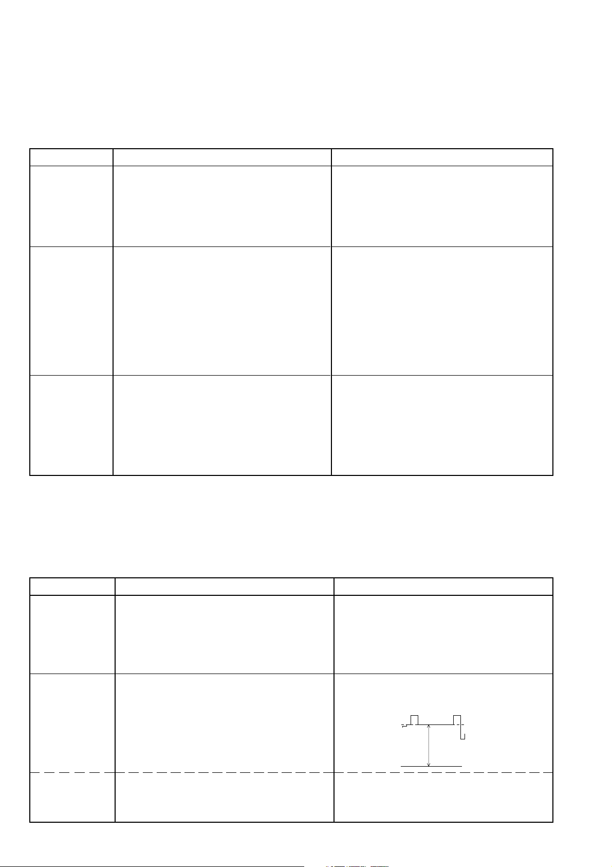
2. Picture Geometry
Measuring instruments: Colour video generator, dual-channel oscilloscope with 10:1 test probe.
Start with the vertical slope when adjusting the geometry!
Service works after replacement or repair:
- Horizontal and vertical deflection and replacement of the picture tube: alignment 2.1, 2.2, 3.1…3.3
- Bridge coil L53074: Only necessary after unskillful manipulation of the horizontal deflection: alignment 2.3
NVM IC82005: alignment 1.2 …1.7, 2.1, 2.2, 3.1, 3.3
Alignment Preparations Alignment Process
2.1 Vertical Slope
2.2 Horizontal Shift
2.3 Bridge Coil
L53074
Call up the "Vertical Slope" menu via "Ǻ" (DIALOG CENTER)
–> "OK" –> SERVICE –> "OK" –> Service Code "8500" –
> "GEOMETRY"
Max. brightness.
Call up dialog line "Horizontal Width" via "Ǻ" (DIALOG
CENTER) –> "OK" –> SERVICE –> "OK" –> Service Code
"8500" –> "GEOMETRY" –> "OK" and reduce the width of
the picture using button Ǹ or Ƿ.
Call up dialog line "Horizontal Shift".
Bridge coil L53074 is adjusted in the factory and this
setting must not be changed.
Call up dialog line "Horizontal Width" via "Ǻ" (DIALOG
CENTER) –> "OK" –> SERVICE –> "OK" –> Service Code
"8500" –> "GEOMETRY" –> "OK".
Set Horizontal Width to minimum.
Oscilloscope channel 1: collector T53001.
Oscilloscope channel 2: cathode D53072.
Adjust the center line of the test pattern in the dialog line
"Vertical Slope" (typ. 30…33) with button Ǹ or Ƿ so that it
is just still visible.
Press button "Ǻ" twice (GEOMETRY –> SERVICE) and
terminate the dialog line "End" with "with mem.".
The picture geometry is adjusted to the value last stored
whenever the TV set is switched on.
Position the picture content in the middle of the raster using
button Ǹ or Ƿ.
Re-adjust the horizontal width according to the test pattern.
With connector "ST-Shift" on the chassis (option), position
the test pattern in the middle of the screen.
Dependent on the scanning spread of the picture tube this
connector may be retrofitted, connected the other way
round, or the rating of the resistor may be changed.
Press button "Ǻ" twice (GEOMETRY –> SERVICE) and
terminate the dialog line "End" with "with mem.".
The picture geometry is adjusted to the value last stored
whenever the TV set is switched on.
Check the oscillograms for the same pulse width and readjust it if necessary with coil L53074.
Adjust the horizontal width according to the test pattern.
3. CRT Panel
Measuring instruments: High-resistance voltmeter, dual-channel oscilloscope with 10:1 test probe.
Service works after replacement or repair:
- CRT, CRT panel: alignment 2.1, 2.2, 3.1…3.3
- NVM IC82005: alignment 1.2 …1.7, 2.1, 2.2, 3.1, 3.3
Alignment Preparations Alignment Process
3.1 White Balance
3.2 Screen Grid
Voltage U
G2
3.3 Screen Grid
Voltage U
via menu
G2
"Cut-off align"
Feed in a grey scale black/white test pattern with burst.
Contrast ({) to maximum.
Colour contrast (i) to mid-position.
Screen brightness (v) to mid-position.
Call up dialog line "WHITE ADJUSTMENT" via "Ǻ"
(DIALOG CENTER) –> "OK" –> SERVICE –> "OK" –>
Service Code "8500".
TV set in AV position.
Feed in a black raster.
Screen brightness: Grey raster just becoming dark.
Connect the voltmeter via 220kΩ to test points R, G and B.
Determine the point with the highest voltage level.
Voltmeter (220kΩ) or oscilloscope to test point with highest
voltage level.
Call up dialog line "Cut-off align" via "Ǻ" (DIALOG CENTER)
–> "OK" –> SERVICE –> "OK" –> Service Code "8500".
Confirm with "OK".
With button Ǹ or Ƿ set the values for "Green" or "Blue" so
that the picture becomes achromatic.
Check the white balance at minimum contrast and maximum
contrast.
Terminate the dialog line "End" with "with mem.".
Set the voltmeter to read 162.5V±2.5V with adjustment
control UG2 on the picture tube panel.
Or adjust with the oscilloscope as shown below.
With adjustment control U
Focus Block), adjust the line appearing first - red, green,
blue or mixed-colour - so that it is just well visible.
Return to the menu with "OK".
Black level
105-110V
162.5V±2.5V
on the picture tube panel (or
G2
2 - 5

Platinenabbildungen und Schaltpläne / Layout of PCBs and Circuit Diagrams
Chassisplatte
Koordinaten für die Bauteile der Lötseite (Unterseite)
Pos.-Nr./ Koordinaten/
Pos. No. Coordinates
XY
CBR100 110 43
CBR101 130 54
CBR102 168 211
CBR103 116 49
CBR105 99 49
CBR107 137 91
CBR109 165 233
CBR111 145 27
CBR112 131 49
CBR120 41 194
CBR121 73 188
CBR123 73 186
CBR130 136 103
CBR136 97 143
CBR137 44 66
CBR139 82 59
CBR141 118 116
CBR143 161 233
CBR145 144 46
CBR146 176 164
CBR147 116 63
CBR148 156 148
CBR149 162 229
CBR151 115 108
CBR157 86 151
CBR161 20 209
CBR164 28 26
CBR167 180 228
CBR173 109 46
CBR174 170 102
CBR175 133 165
CC31019 140 228
CC31047 139 237
CC31051 140 224
CC31052 140 222
CC32026 53 99
CC32109 135 98
CC32110 127 99
CC32118 124 97
CC32121 105 89
CC32122 105 86
CC32123 105 84
CC32124 105 81
CC32301 61 194
CC32302 62 202
CC32303 66 194
CC32304 73 195
CC32306 69 194
CC32307 40 173
CC32308 40 169
CC32309 32 187
CC32310 29 187
CC32311 35 173
CC32312 35 169
CC32313 30 173
CC32314 27 187
CC32315 24 187
CC32316 30 169
CC32317 25 173
CC32318 25 169
CC32319 21 187
CC32321 20 173
CC32322 20 169
CC32328 41 202
CC32333 56 206
CC32336 60 25
CC32337 60 28
CC32341 41 179
CC32345 35 187
CC32347 34 194
CC32348 62 211
CC32350 40 186
CC32365 58 202
CC32401 120 87
CC32412 153 200
Pos.-Nr./ Koordinaten/
Pos. No. Coordinates
XY
CC32413 148 160
CC32422 119 185
CC33014 139 127
CC33016 145 133
CC33017 137 133
CC33018 145 156
CC33020 133 168
CC33021 152 158
CC33025 145 130
CC34022 130 127
CC34027 113 148
CC34032 75 89
CC34037 119 156
CC34039 121 130
CC34041 110 148
CC34042 105 145
CC34043 116 165
CC34044 101 164
CC34061 112 140
CC34064 130 132
CC34067 133 132
CC34072 148 156
CC40022 42 66
CC40026 38 64
CC40042 38 86
CC40046 38 77
CC43001 49 194
CC43003 29 228
CC43006 52 194
CC43008 23 228
CC43011 28 194
CC43013 22 244
CC43016 31 194
CC43018 15 228
CC43021 43 194
CC43023 89 230
CC43026 46 194
CC43028 86 230
CC43031 23 194
CC43033 83 244
CC43036 26 194
CC43038 79 231
CC43046 100 247
CC43047 86 253
CC43055 149 247
CC43057 39 247
CC43058 33 247
CC43061 47 247
CC43073 108 230
CC43074 149 242
CC43099 122 242
CC43248 72 247
CC43259 120 203
CC43261 95 228
CC43281 99 198
CC43283 115 224
CC43284 77 169
CC43286 140 26
CC46004 145 67
CC46014 80 54
CC46015 77 54
CC46016 82 49
CC46017 102 49
CC46021 104 49
CC46022 107 49
CC46023 82 34
CC46024 77 59
CC46026 81 43
CC46027 79 34
CC50003 192 226
CC50004 198 221
CC50011 179 200
CC50012 173 203
CC50014 182 201
CC50017 176 203
Pos.-Nr./ Koordinaten/
Pos. No. Coordinates
CC52216 132 156
CC52217 133 148
CC52246 128 161
CC52248 124 156
CC52266 129 67
CC55001 161 158
CC57004 163 123
CC57007 157 158
CC57016 170 105
CC57021 101 133
CC61038 182 146
CC61039 179 146
CC61041 181 152
CC61051 181 104
CC61058 181 100
CC61059 160 71
CC61060 178 100
CC61061 181 58
CC61062 181 52
CC61064 178 58
CC80001 105 30
CC80002 108 30
CC80007 99 25
CC81003 99 20
CC81006 182 8
CC81007 97 59
CC81008 145 35
CC81012 96 67
CC81013 84 69
CC81016 119 49
CC81020 120 77
CC81021 82 30
CC81023 113 29
CC81026 116 29
CC81028 119 29
CC81032 122 29
CC81033 89 49
CC81034 92 49
CC81036 94 49
CC81038 98 43
CC81041 93 30
CC81042 90 30
CC81043 87 30
CC81046 122 25
CC81048 129 29
CC81050 108 76
CC81055 102 76
CC81057 125 29
CC81058 126 72
CC81059 96 80
CC81062 113 43
CC81082 88 16
CC81508 176 9
CC82001 141 50
CC82004 132 38
CD32411 144 185
CD32421 141 185
CD80007 97 25
CIC32410 128 84
CIC43050 157 245
CL31051 88 219
CL31052 91 219
CR31003 77 201
CR31006 77 199
CR31008 69 20
CR31009 77 11
CR31011 67 45
CR31019 131 219
CR31021 140 230
CR31022 132 215
CR31029 89 215
CR31039 91 215
CR31041 124 213
XY
Chassis Board
Coordinates of the Components on the Solder Side (Bottom Side)
Pos.-Nr./ Koordinaten/
Pos. No. Coordinates
XY
CR31042 129 215
CR31043 131 211
CR31044 131 204
CR31045 131 208
CR31046 142 237
CR31047 131 234
CR31048 150 232
CR32021 135 185
CR32026 53 106
CR32101 124 100
CR32102 118 110
CR32103 132 120
CR32104 118 106
CR32105 127 92
CR32107 120 101
CR32108 125 117
CR32109 130 99
CR32110 133 103
CR32111 114 97
CR32112 114 89
CR32113 108 98
CR32114 110 98
CR32119 119 92
CR32124 101 82
CR32128 90 99
CR32129 94 98
CR32131 88 115
CR32132 119 90
CR32133 109 82
CR32141 105 97
CR32142 105 99
CR32143 105 94
CR32144 105 92
CR32150 114 86
CR32300 73 190
CR32301 73 192
CR32302 54 194
CR32303 37 187
CR32304 18 190
CR32305 15 192
CR32306 85 172
CR32307 42 173
CR32309 33 178
CR32310 30 178
CR32311 37 173
CR32313 32 173
CR32314 27 178
CR32315 25 178
CR32317 27 173
CR32318 22 178
CR32319 22 173
CR32334 73 183
CR32335 55 186
CR32336 38 194
CR32337 58 174
CR32338 51 186
CR32339 58 20
CR32340 61 20
CR32341 46 186
CR32342 43 186
CR32345 43 159
CR32360 35 204
CR32364 62 187
CR32401 127 77
CR32402 125 77
CR32403 120 82
CR32404 130 72
CR32406 120 84
CR32407 120 80
CR32408 122 77
CR32409 151 117
CR32410 129 77
CR32411 152 172
CR32412 155 197
CR32414 155 194
Pos.-Nr./ Koordinaten/
Pos. No. Coordinates
XY
CR32416 144 164
CR32417 132 77
CR32418 134 77
CR32419 149 164
CR32420 138 185
CR32431 148 174
CR32432 148 184
CR33014 141 132
CR33016 145 133
CR33018 160 177
CR33019 102 173
CR33020 142 156
CR33025 145 125
CR34032 75 86
CR34033 74 92
CR34036 94 133
CR34037 97 133
CR34038 100 139
CR34039 101 157
CR34040 102 155
CR34041 121 156
CR34042 108 148
CR34043 116 156
CR34044 110 170
CR34045 107 155
CR34046 86 146
CR34047 88 149
CR34048 93 143
CR34049 90 144
CR34053 112 108
CR34054 105 104
CR34055 93 115
CR34057 137 131
CR34058 152 101
CR34059 150 101
CR34061 106 141
CR34062 64 122
CR34064 125 125
CR34067 118 125
CR34076 101 142
CR40021 28 113
CR40026 38 67
CR40031 20 113
CR40041 25 113
CR40046 38 81
CR40051 23 113
CR40058 16 107
CR40059 27 104
CR40060 21 101
CR40061 15 74
CR40062 38 69
CR40064 15 72
CR40070 18 113
CR40071 16 109
CR40072 16 142
CR41011 38 18
CR41022 16 35
CR41023 21 35
CR41032 28 28
CR41033 31 27
CR43001 48 202
CR43002 44 215
CR43003 32 228
CR43006 51 202
CR43008 20 228
CR43011 29 203
CR43013 17 244
CR43016 32 203
CR43018 18 228
CR43021 44 202
CR43023 91 230
CR43026 46 202
CR43028 83 230
CR43031 21 203
CR43033 80 244
Pos.-Nr./ Koordinaten/
Pos. No. Coordinates
XY
CR43036 23 203
CR43038 76 231
CR43040 81 253
CR43041 89 244
CR43042 86 244
CR43043 30 244
CR43044 27 244
CR43045 25 244
CR43046 98 243
CR43047 93 243
CR43048 155 238
CR43051 161 252
CR43052 111 243
CR43053 109 247
CR43054 36 247
CR43055 109 251
CR43056 159 252
CR43057 161 236
CR43058 168 246
CR43061 151 252
CR43062 46 243
CR43063 51 243
CR43066 38 243
CR43067 33 243
CR43072 106 243
CR43073 108 226
CR43074 107 247
CR43076 169 253
CR43077 166 246
CR43078 121 230
CR43079 118 219
CR43095 118 243
CR43096 115 244
CR43097 102 227
CR43181 157 252
CR43182 157 238
CR43183 153 252
CR43184 161 238
CR43241 57 244
CR43242 60 244
CR43243 62 244
CR43246 62 249
CR43247 55 244
CR43249 114 203
CR43250 103 203
CR43254 120 200
CR43255 118 200
CR43256 107 202
CR43257 158 214
CR43258 116 203
CR43259 116 195
CR43261 103 221
CR43262 111 223
CR43263 105 221
CR43265 66 175
CR43266 100 221
CR43267 63 231
CR43271 94 219
CR43274 85 178
CR43276 115 219
CR43277 105 226
CR43278 111 203
CR43279 110 199
CR43281 99 200
CR43282 108 221
CR43283 96 219
CR43284 85 222
CR43285 64 175
CR43286 99 202
CR43287 99 204
CR43288 152 44
CR43289 155 39
CR43290 136 26
CR46001 87 49
CR46003 134 67
3 - 1

Pos.-Nr./ Koordinaten/
Pos. No. Coordinates
XY
CR46004 150 66
CR46007 142 67
CR46008 148 67
CR46009 140 67
CR46011 148 71
CR46012 149 62
CR46013 142 62
CR46016 84 49
CR46022 85 34
CR46024 80 59
CR46026 84 43
CR46027 79 49
CR50002 180 196
CR50004 189 232
CR50012 177 194
CR52216 139 149
CR52217 156 150
CR52247 125 161
CR52250 159 165
CR52251 131 139
CR52252 140 156
CR52253 170 226
CR52254 166 226
CR52255 152 174
CR52256 120 149
CR52263 178 225
CR52266 132 67
CR55001 180 180
CR55002 176 186
CR57001 174 119
CR57002 169 160
CR57003 166 126
CR57004 161 119
CR57006 168 126
CR57008 167 114
CR57012 161 117
CR57020 167 152
CR57021 167 71
CR57022 165 71
CR57101 181 169
CR57102 154 114
CR57103 151 105
CR57104 181 172
CR57105 181 165
CR57113 169 238
Pos.-Nr./ Koordinaten/
Pos. No. Coordinates
XY
CR57116 175 253
CR57117 177 247
CR57121 172 253
CR57124 178 232
CR61041 181 158
CR61044 174 134
CR61046 153 80
CR61051 181 109
CR61054 161 67
CR61056 163 71
CR80001 106 34
CR80007 101 29
CR81001 131 16
CR81002 94 11
CR81004 108 12
CR81005 101 31
CR81006 145 32
CR81007 97 49
CR81008 130 57
CR81009 100 34
CR81010 86 43
CR81011 80 66
CR81012 87 73
CR81013 84 73
CR81014 104 64
CR81015 132 13
CR81016 114 49
CR81017 87 69
CR81018 108 22
CR81019 115 25
CR81020 81 78
CR81021 95 34
CR81022 96 43
CR81023 114 33
CR81025 111 22
CR81026 117 33
CR81027 117 43
CR81028 119 33
CR81029 119 43
CR81030 94 20
CR81031 89 49
CR81032 122 33
CR81033 84 59
CR81034 92 59
CR81035 92 49
Pos.-Nr./ Koordinaten/
Pos. No. Coordinates
XY
CR81036 94 59
CR81037 98 34
CR81038 79 75
CR81040 89 43
CR81041 93 34
CR81042 90 34
CR81043 87 34
CR81044 91 43
CR81045 93 43
CR81046 124 33
CR81047 122 43
CR81048 129 33
CR81049 133 26
CR81050 84 100
CR81055 101 105
CR81056 124 43
CR81057 126 33
CR81059 97 104
CR81060 116 82
CR81061 105 76
CR81062 101 108
CR81063 96 83
CR81064 75 109
CR81066 121 49
CR81067 124 49
CR81068 126 49
CR81072 130 222
CR81073 82 23
CR81074 82 20
CR81076 82 26
CR81077 87 26
CR81080 91 26
CR81081 83 16
CR81082 86 16
CR81083 103 43
CR81084 108 43
CR81086 112 49
CR81087 109 49
CR81500 175 39
CR81501 172 39
CR81502 149 24
CR81503 178 42
CR81505 145 24
CR81507 173 9
CR81508 179 9
Pos.-Nr./ Koordinaten/
Pos. No. Coordinates
XY
CR81509 159 40
CR81511 157 76
CR82001 136 52
CR82003 128 43
CR82004 126 43
CR82006 132 40
CR82007 136 39
CR82008 105 19
CT31005 78 16
CT31010 63 48
CT31020 60 65
CT31030 63 56
CT32105 131 117
CT32111 114 102
CT32119 119 96
CT32122 109 86
CT32123 109 93
CT32124 100 97
CT32128 94 95
CT32132 114 93
CT32308 41 165
CT32310 36 165
CT32312 31 165
CT32315 26 165
CT32318 21 165
CT32415 138 169
CT32430 142 169
CT32431 148 169
CT34031 101 147
CT34075 91 127
CT40059 16 101
CT41022 16 38
CT41030 21 30
CT43095 119 247
CT43244 58 249
CT43246 67 247
CT43255 120 195
CT43289 151 38
CT43290 59 135
CT46004 145 62
CT46009 138 62
CT52253 173 226
CT57005 167 120
CT57020 166 76
CT57021 164 104
Pos.-Nr./ Koordinaten/
Pos. No. Coordinates
XY
CT57103 176 173
CT57112 173 238
CT57113 173 245
CT57124 173 232
CT61043 174 139
CT61053 166 65
CT81010 80 70
CT81015 99 67
CT81030 73 28
CT81058 112 77
CT81080 87 22
CT81091 127 15
CT81502 168 40
CT81503 173 32
CT81508 175 15
CT81511 157 80
CT82006 127 21
_CBR154 92 11
_CC32107 129 109
_CC32111 113 82
_CC32152 136 127
_CC32154 142 109
_CC32411 134 156
_CC32451 63 167
_CC32452 59 169
_CC34069 150 132
_CC40028 28 59
_CC40032 10 69
_CC40036 24 73
_CC40038 39 61
_CC40048 16 88
_CC40049 30 86
_CC40052 16 96
_CC40056 16 91
_CC40059 24 101
_CC43289 150 44
_CC46020 100 58
_CC57003 138 156
_CC81063 148 51
_CC81081 83 16
_CD32152 139 117
_CD32153 136 117
_CR31013 64 62
_CR31018 62 43
Pos.-Nr./ Koordinaten/
Pos. No. Coordinates
XY
_CR31028 60 61
_CR31038 63 52
_CR32106 120 106
_CR32151 133 109
_CR32152 137 124
_CR32153 138 107
_CR32156 138 109
_CR32157 138 113
_CR32158 139 103
_CR32326 109 185
_CR32327 112 185
_CR32421 136 77
_CR32422 138 77
_CR32426 114 185
_CR32433 157 175
_CR32436 155 192
_CR32437 157 178
_CR32438 153 178
_CR32439 157 180
_CR32441 133 185
_CR32451 61 159
_CR32452 56 157
_CR32453 56 159
_CR32454 57 169
_CR34034 80 105
_CR34071 162 136
_CR34072 137 67
_CR40028 28 62
_CR40036 15 69
_CR40038 35 61
_CR40042 30 113
_CR40048 16 84
_CR40049 30 89
_CR40056 16 94
_CR43004 26 228
_CR43014 20 244
_CR81003 100 43
_CR81024 115 43
_CR81091 106 43
_CR81092 92 16
_CT32435 158 184
_CT32440 153 184
_CT32453 58 164
_CT32454 53 165
3 - 2

Chassisplatte
Koordinaten für die Bauteile der Bestückungsseite (Oberseite)
Chassis Board
Coordinates of the Components on the Components Side (Top Side)
Pos.-Nr./ Koordinaten/
Pos. No. Coordinates
XY
ASIS01 135 21
ASIS02 135 31
ASIS03 98 29
ASIS04 131 43
ASIS05 131 46
ASIS06 74 67
ASIS07 147 86
ASIS08 144 83
ASIS09 94 111
ASIS10 104 110
ASIS11 109 110
ASIS12 159 151
ASIS13 170 44
ASIS14 147 91
ASIS15 175 46
ASIS16 108 71
BR102 170 178
BR104 114 14
BR105 61 125
BR106 154 108
BR107 123 16
BR108 117 14
BR109 120 16
BR110 347 236
BR111 284 148
BR112 185 167
BR113 148 74
BR114 147 71
BR115 68 224
BR119 24 74
BR123 278 11
BR124 159 24
BR126 131 121
BR127 199 167
BR128 203 155
BR129 186 184
BR130 208 165
BR131 191 160
BR132 121 214
BR133 168 137
BR135 67 147
BR139 80 92
BR140 60 90
BR142 104 46
BR144 63 81
BR147 211 132
BR150 194 166
BR151 185 136
BR155 27 149
BR156 177 102
BR159 25 149
BR160 61 84
BR161 79 125
BR163 68 38
BR164 71 35
BR167 217 176
BR169 289 175
BR171 161 54
BR173 200 133
BR175 35 149
BR177 116 144
BR178 123 144
BR179 18 194
BR180 72 189
BR181 63 222
BR183 109 199
BR184 166 16
BR185 88 89
BR186 59 117
BR187 138 26
BR189 141 26
BR190 135 26
BR192 264 246
BR194 192 10
BR195 275 16
Pos.-Nr./ Koordinaten/
Pos. No. Coordinates
XY
BR196 199 211
BR197 209 246
BR198 192 144
BR202 9 91
BR206 93 105
BR208 43 9
BR209 195 226
BR212 127 183
BR213 101 108
BR214 98 23
BR215 156 214
BR216 176 126
BR217 121 117
BR218 45 230
BR219 185 94
BR220 108 230
BR221 49 144
BR222 49 147
BR223 127 144
BR224 23 115
BR228 71 33
BR232 158 59
BR233 108 77
BR234 250 98
BR235 14 43
BR236 29 55
BR238 80 84
BR239 73 98
BR240 158 62
BR243 47 37
BR245 65 25
BR246 335 49
BR247 41 177
BR248 45 215
BR251 142 246
BR15800 22 149
BR31001 94 189
BR31002 74 128
BR31003 56 128
BR31004 94 186
BR31006 96 181
BR31007 75 115
BR31008 57 71
BR31051 75 211
BR31052 73 211
BR32041 125 215
BR32301 97 177
BR32337 46 156
BR32342 61 151
BR32358 14 173
BR32359 18 213
BR32364 58 191
BR32418 134 67
BR34038 94 144
BR34039 96 144
BR34045 92 163
BR40063 42 80
BR40070 19 153
BR43052 142 250
BR43057 165 245
BR43061 61 222
BR43097 95 192
BR43098 162 234
BR43245 108 211
BR43255 106 211
BR43257 160 90
BR43258 164 94
BR43278 96 183
BR43281 108 195
BR46022 125 109
BR50027 209 209
BR52002 210 226
BR52006 215 241
BR53001 269 220
BR53011 239 150
Pos.-Nr./ Koordinaten/
Pos. No. Coordinates
XY
BR53076 289 178
BR53077 287 178
BR53078 296 187
BR54002 269 190
BR55001 184 188
BR55002 196 190
BR55003 177 199
BR55004 186 233
BR55006 180 196
BR55007 189 235
BR55008 200 179
BR57021 155 111
BR60012 294 84
BR60021 238 100
BR61020 262 143
BR61027 276 136
BR61028 175 100
BR61307 328 21
BR61308 327 6
BR61312 341 15
BR62500 286 65
BR62501 264 76
BR62502 240 44
BR62503 240 21
BR62504 236 59
BR81006 162 20
BR81007 160 29
BR81020 63 77
BR81033 63 74
BR81041 69 33
BR81042 66 38
BR81043 68 35
BR81061 161 50
BR81073 71 48
BR81074 75 123
BR82006 132 26
C31001 70 137
C31041 149 229
C31042 157 225
C31044 156 203
C31046 159 193
C32021 120 175
C32023 61 111
C32024 60 96
C32108 135 98
C32327 46 207
C32332 54 206
C32334 57 121
C32343 24 210
C32346 31 210
C32360 37 208
C32364 60 210
C32423 112 175
C33019 156 161
C34021 127 128
C34041 116 160
C34063 156 155
C40011 23 61
C40012 26 36
C40014 18 81
C40061 19 74
C40062 29 49
C41011 31 20
C41022 11 36
C41032 16 28
C43002 29 220
C43007 35 222
C43012 10 230
C43017 21 220
C43022 42 222
C43027 48 222
C43032 73 226
C43037 55 222
C43079 118 228
C43098 124 228
Pos.-Nr./ Koordinaten/
Pos. No. Coordinates
XY
C43249 69 239
C43266 95 225
C43282 112 223
C46001 74 61
C50013 195 149
C50016 202 191
C50026 213 191
C50027 214 209
C52001 204 234
C52002 193 236
C52003 200 234
C52004 226 221
C52006 213 234
C52247 125 169
C52254 156 169
C53001 290 221
C53002 253 228
C53006 281 221
C53007 264 221
C53009 234 244
C53011 304 246
C53013 235 236
C53016 353 220
C53017 353 200
C53031 292 188
C53032 288 188
C53072 235 221
C53073 222 195
C54001 290 166
C54002 274 161
C54004 214 151
C54011 251 158
C54012 228 143
C55003 192 188
C55004 205 182
C57016 169 82
C60001 288 105
C60002 335 40
C60007 281 99
C60009 334 89
C60010 340 89
C60011 314 49
C60013 335 58
C60014 325 44
C60016 325 35
C60022 217 98
C60023 237 82
C60024 197 83
C60026 231 78
C60027 203 79
C60036 346 34
C60037 317 57
C60038 329 68
C61016 345 154
C61017 346 179
C61026 313 159
C61027 296 152
C61036 292 139
C61037 264 128
C61042 192 136
C61052 192 123
C61056 296 127
C61057 280 123
C61063 175 52
C61301 320 13
C61311 338 15
C62021 195 25
C62022 195 19
C62048 301 111
C62501 249 68
C62502 213 31
C62505 201 38
C81061 148 52
C81072 148 235
C81073 78 25
Pos.-Nr./ Koordinaten/
Pos. No. Coordinates
XY
D31001 69 143
D31007 73 15
D32128 82 95
D40064 10 77
D40066 16 51
D43284 71 168
D43292 53 140
D50011 189 184
D50013 189 164
D50014 190 219
D50016 199 194
D52001 200 241
D53003 293 205
D53071 242 220
D53072 222 215
D54001 319 169
D54002 269 156
D54011 250 152
D55004 206 190
D57011 164 104
D57012 167 104
D57013 172 104
D57014 170 131
D57021 155 111
D57023 162 80
D57101 172 169
D57122 177 233
D60005 316 78
D60006 321 82
D60007 306 84
D60012 300 93
D60013 321 49
D60023 213 73
D60037 315 66
D61016 353 160
D61026 317 154
D61036 290 136
D61056 298 124
D81012 81 77
D81020 110 65
D81051 118 65
D81052 121 65
D81053 123 65
D81501 270 20
EUROAV01 39 244
EUROAV02 99 244
F32020 139 180
F32101 127 93
F32109 127 102
F32121 99 89
F32410 148 198
F32412 139 168
F33025 145 125
IC32000 45 190
IC32420 116 185
IC34015 124 144
IC40000 33 74
IC43280 107 211
IC50020 187 205
IC60010 328 54
IC61040 184 155
IC61050 184 105
IC61060 184 55
IC61310 328 13
IC80000 106 25
IC81050 105 46
IC82000 138 50
IC82005 138 39
IND01 55 231
IND02 22 231
L31041 64 153
L31043 125 201
L32023 67 111
L32026 58 102
Pos.-Nr./ Koordinaten/
Pos. No. Coordinates
XY
L32109 131 109
L32342 52 164
L32343 52 166
L43098 162 234
L46021 104 61
L46022 125 110
L50027 209 209
L53001 270 239
L53002 244 236
L53003 266 234
L53011 294 239
L53012 247 141
L53021 246 191
L53074 247 171
L54002 272 186
L55006 217 167
L60006 340 83
L60012 309 99
L61016 350 148
L61026 335 149
L61036 330 149
L61056 320 144
L62501 238 33
L81062 72 41
M01 92 131
MONO01 110 192
MONO01 73 167
MONO02 106 186
MONO02 52 188
NETZ01 283 53
NETZ02 275 53
NETZ03 213 66
NETZ04 226 63
NETZSCH. 287 35
OK60031 316 24
PFC 232 55
PFC02 231 63
Q32305 66 208
Q34043 115 167
Q34044 102 167
Q80001 106 34
R21117 305 174
R32023 79 102
R32346 49 161
R32359 11 214
R32413 162 165
R34031 88 86
R34056 114 125
R34057 110 125
R34058 106 125
R34059 103 125
R34062 80 120
R34063 85 112
R34066 85 109
R40011 49 36
R40012 49 46
R40066 16 48
R41022 30 149
R41030 33 149
R43050 61 87
R43098 130 247
R43099 127 239
R43248 83 249
R43291 51 133
R43292 51 131
R50001 169 217
R50003 169 220
R50011 203 152
R50021 196 210
R50022 201 210
R50023 205 210
R50024 205 203
R50026 208 199
3 - 3

Pos.-Nr./ Koordinaten/
Pos. No. Coordinates
XY
R52001 209 226
R52002 290 245
R52004 214 221
R52006 215 241
R53001 279 236
R53002 290 208
R53011 288 234
R53016 272 172
R53021 263 196
R54001 329 171
R54002 269 190
R54003 280 191
R54012 269 152
R55003 196 175
R55006 204 171
R57007 164 173
R57011 168 114
R57016 169 104
R57017 163 136
R57118 177 246
R60001 340 63
R60002 345 45
R60003 345 63
Pos.-Nr./ Koordinaten/
Pos. No. Coordinates
XY
R60004 349 43
R60005 319 66
R60006 322 66
R60007 340 45
R60008 279 85
R60009 274 100
R60012 294 84
R60013 331 64
R60014 329 40
R60015 309 99
R60016 295 96
R60018 306 39
R60021 239 73
R60029 296 78
R60031 335 33
R60032 316 31
R60033 315 35
R60036 345 30
R60037 314 38
R61018 339 156
R61019 270 148
R61027 217 127
Pos.-Nr./ Koordinaten/
Pos. No. Coordinates
XY
R61043 177 153
R61053 170 65
R61301 303 11
R61302 310 16
R61303 310 7
R61304 278 14
R61306 280 9
R61311 334 14
R61312 341 15
R61313 347 16
R61314 354 126
R62049 294 111
R62505 203 58
R81020 114 65
R81051 118 65
R81052 121 65
R81053 123 65
R81054 126 63
R81504 160 33
SI40012 46 54
SI40070 41 15
SI52001 201 221
Pos.-Nr./ Koordinaten/
Pos. No. Coordinates
XY
SI60001 256 108
SI61026 321 160
SI61036 306 142
SI61056 306 133
SI62501 269 76
STBR 205 138
STCI01 61 15
STE 220 57
STH 19 19
STJOCH 231 174
STKB\IR 144 15
STLSL 15 59
STLSL01 17 58
STLSR 22 90
STLSR01 24 88
STMASSE 352 249
STNETZ01 272 60
STNF01 10 135
STNF02 10 193
STPIP01 146 215
STPIP02 146 91
STPIP03 101 160
STRGB 107 114
Pos.-Nr./ Koordinaten/
Pos. No. Coordinates
XY
STSB 81 173
STSHIFT 274 221
STSKY 40 156
T52001 208 234
T53001 278 244
T55002 198 246
T60006 316 69
T61301 310 12
T81501 173 26
TR52001 222 231
TR53010 322 213
TR53011 321 211
TR61000 329 118
TR61001 333 121
TUNER 136 222
_BR32451 67 166
_BR34073 80 117
_BR40042 57 68
_BR43005 35 198
_BR43009 49 193
_BR52001 201 222
_BR53001 270 239
Pos.-Nr./ Koordinaten/
Pos. No. Coordinates
XY
_BR53012 239 152
_BR53072 235 221
_BR53074 285 181
_BR61040 274 132
_BR61301 303 11
_C32438 151 189
_C32454 48 173
_C34071 155 136
_F32152 145 115
_F32153 145 119
_L32451 62 167
_R40014 44 30
_R41011 41 21
_R53074 260 174
_R61305 316 10
_R61307 328 21
_R61308 327 6
_STKA 97 125
_STMP 102 15
3 - 4

Chassisplatte / Chassis Board
70cm VC
70cm PHILIPS
152V
152V
+A
Bestückungsseite, Ansicht von oben / Component Side, Top View
39 3235 34 38 40 373033 45 36 46 46A
0 10 20 30 40 50 60 70 80 90 100 110 120 130 140 150 160 170 180 190 200 210 220 230 240 250 260 270 280 290 300
X
0
Y
29304-764.22 4B(17)
15
BR245
BR228
BR164
BR163
L81062
BR81073
C46001
ASIS6
BR144
BR139
BR239
R32023
L32023
R34066
R34063
BR31007
R34062
BR31002
C31001
D31001
BR135
L31041
MONO1-
_BR32451
D43284
BR180
126
Q32305
BR31052
BR181
BR115
220
121
C43249
D31007
15
ASIS3
_ST-MP
1
IC80000
31
C81073
BR214
Q80001
BR142
27 52
1
D81012
L46021
D81020
ASIS16
1
BR233
R34031
BR238
BR161
15
ST-SB
1
BR31051
C43032
BR185
D32128
BR81074
1
EURO-AV2
BR206
M-1
BR34038
ST-PIP3
BR31004
BR31001
BR43097
C43266
_ST-KA
BR43278
IC43280
F32121
ASIS11
BR213
1
1
ASIS10
ASIS9
R34059
R34058
13
1
BR34039
Q34044
BR34045
BR32301
BR31006
BR43281
20
1 10
BR43255
BR43245
IC34015
28
17
Q34043
C32423
1
MONO2
814
MONO1
BR183
C43282
BR220
R43248
BR108
BR104
IC81050
R81020
R81051
F32109
BR46022
L46022
1
ST-RGB
17
R34056
R34057
BR177
C34041
C32021
1
C43079
BR107
BR109
R81052
R81053
D81051
D81052
D81053
F32101
C32108
BR217
BR178
17
IC32420
L31043
11
BR132
ASIS1
ASIS2
126
R81054
_F32152
_F32153
BR223
C52247
BR212
BR32041
C43098
111
R43099
R43098
BR82006
ASIS4
ASIS5
1
ST-KB\IR
BR190
BR187
BR189
1
14
1
1
IC82005
58
14
IC82000
58
BR32418
BR114
BR113
ST-PIP2
17
L32109
BR126
C34021
F33025
F32412
F32020
TUNER
15
C81072
C81061
1
ASIS8
1
ASIS7
1
ASIS14
1
5629
ST-PIP1
BR251
BR43052
19
BR124
BR81007
BR81061
BR232
BR240
BR43257
BR106
D57021
BR57021
_C34071
ASIS12
C52254
_C32438
F32410
C31041
BR184
BR81006
R81504
D57023
BR43258
D57011
1
C34063
C33019
R32413
R57007
C31046
C31044
BR215
C31042
BR43098
L43098
ASIS13
+M
BR171
R61053
C57016
D57012
R57016
R57011
R57017
BR102
R50001
R50003
BR43057
E B
T81501
1
C61063
BR61028
D57013
D57014
BR216
BR133
R61043
D57101
BSO-PL.
D57122
ASIS15
1
BR156
IC61040
BR55006
BR55003
BR55001
IC50020
R57118
BR194
C62022
C62021
C62505
IC61060
R62505
13
D60023
-+
C60027
BR219
C60024
IC61050
13
BR151
C61052
C61042
BR198
C50013
BR131
13
BR150
BR112
D50013
R55003
BR55008
D50011
BR129
D50014
BR55004
C50016
BR55002
C55003
D50016
R50021
BR196
113
BR209
C52002
SI52001
C52003
D52001
T55002
BR55007
C62502
ST-E
DVB-S
-+
C60022
BR173
R50011
BR127
R50024
T315mA
ST-BR
15
BR128
BR130
R55006
R50026
R50022
_BR52001
BR52002
C52001
GS
BR197
C54004
C55004
D55004
C50026
BR50027
R50023
L50027
R52004
R52001
T52001
BR147
BR167
C50027
C52006
E B
BR52006
R52006
R61027
L55006
D53072
L62501
BRAUN
PFC
13
BLAU
C60026
C60023
C54012
17
ST-JOCH
C53073
C52004
_BR53072
TR52001
C53009
R61306
BR123
BR62503
BR62502
BR62504
D81501
NETZSCHALTER
ST-NETZ1
R60021
SI62501
T2,5A
C62501
BR62501
(WB T4A)
BR60021
BR234
SI60001
T1,6A
(WB T2,5A)
C61037
BR53011
L53012
_BR61040
BR61020
CUC2031/32
50/51/58/
59/80
_BR53012
R61019
CUC2030 T2,5A
D54011
D54002
C54011
_R53074
R53016
L53074
L54002
BR54002
R54002
L53021
DYN-FOK. / PANORAMA VIEW / UG 2
C53072
D53071
C53007
ST-SHIFT
C53002
12
C53013
L53002
BR53001
L53001
L53003
_BR53001
BR192
BR195
NETZ2
1
NETZ2
R60008
R60009
T4A
C54002
C53032
R54003
R53021
R53001
R61304
NETZ1
NETZ1
BR62500
BR61027
D61036
R54012
C54001
BR53077
_BR53074
C53006
T53001
100
110
120
130
140
150
160
170
180
190
200
210
220
230
240
250
10
20
30
40
50
60
70
80
90
LOETRICHTUNG
C41011
(CUC2040 T1,6A)
ST-H
C41022
R40066
D40066
ST-LSL1
ST-LSL
BR235
C40061
C40012
BR236
13
C40011
12
115
BR119
C40062
13
C41032
D40064
C40014
13
12
ST-LSR1
BR224
R41022
BR159
BR155
IC40000
R41030
BR175
12
BR202
19
ROT
ST-NF1
ST-LSR
BR15800
BR40070
ST-SKY
BR32358
MI-
ST-NF2
BR179
IC32000
_BR43009
_BR43005
19
27 52
C32343
C32360
C32346
R32359
BR32359
C43002
C43012
C43017
IND2
220
EURO-AV1
121
16
C43022
C43007
BR218
T2,5A
_R41011
_R40014
BR243
SI40012
T1,6A
BR40063
R43050
BR186
C32334
BR221
BR222
R32346
BR32337
_C32454
BR247
C32327
BR248
C43027
BR208
SI40070
R40011
(CUC2033/35 T2A)
R40012
_BR40042
BR31008
D43292
L32342
L32343
MONO2-
1
C32332
C43037
IND1
ST-CI1
BR81041
BR81043
BR81042
(CUC2030 T1,25A)
BR81033
BR81020
BR160
BR140
C32024
L32026
C32023
BR105
R43292
R43291
BR32342
_L32451
BR32364
C32364
BR43061
13
_BR61301
1
17
R60029
BR60012
R60012
R60016
D60012
C60001
C60007
C61057
C61056
C61027
BR111
BR169
BR53076
C53031
R53002
1
D53003
C53001
R53011
L53011
R52002
BE
310 320 330 340 350 360
C61301
_R61308
_R61305
13
46
R60033
R60037
C60037
D60037
R60005
R60006
BR61308
58
IC61310
14
BR61307
_R61307
R60036
C60016
R60031
C60002
R60014
C60014
D60013
BR246
14
IC60010
58
R60013
R61311
R61303
T61301
R61301
R61302
OK60031
R60018
EC
R60032
C60011
C60038
D60005
GDS
L60012
R60015
C62048
11
D60006
5
7
D60007
R62049
CUC2033/35/40/
58D/59D
D61056
T2,5A
SI61056
C61036
R21117
T5A
10 2
10
12
L61056
SI61036
C61026
D61026
SI61026
8
T4A
R54001
6
L61036
L61026
D54001
C61017
BR53078
1
A
B
C
D
H
G
TR53010
C53011
E
F
R61312
BR61312
C61311
R60007
C60013
R60001
T60006
L60006
4
C61016
R61018
10
M
L
K
I
R61313
R60002 R60003
C60009
1
TR61001
17
2
D61016
C53017
12
C53016
BR110
C60036
R60004
C60010
TR61000
R61314
L61016
+A
(OPTION A)
+A
1
3
5
2
4
260
54525347 49 50 8 44
Q34043
50A47A 55 42 434151
19 1516 16A201314 177 122122 23 9 10 11
18
3 - 5 3 - 6

Chassisplatte / Chassis Board
CL31051
CR81087
CR81086
CR80001
CR81016
CR81007
CR43263
CR43262
CR43282
CR43277
CR32302
_CR32156
_CR32153
CR43073
CR34042
CR32402
CR32401
CR32403
CR32418
CR32406
CR32408
CR32407
CR32417
_CR32421
_CR32422
CR52256
CR81081
CC81036
CR32409
CR32410
CR57102
CBR175
CC81034
CC81020
CC46017
CC34027
CC34061
CC32345
CC32315
CC32310
CC32301
CC32314
CC32311
CC32347
CC32303
CC32317
CC43001
CC43006
CC43011
CC43016
CC43021
CC43026
CC43031
CC43036
CC32313
CC32309
CC32307
CC32306
_CC32154
CC52216
CC52248
CC34042
CC34041
_CC32411
CC32401
CC32321
_CC57003
CC32319
CC81033
CC80001
CC46021
CC33016
CC34064
CIC43050
CIC32410
CT57021
CT52253
CT32318
CT41022
CT81511
CT41030
CT31030
CT31020
CT31010
CT32124
CT31005
CT57020
CT32122
CT32308
CT43289
CT34031
CT43244
_CT32440
CT57113
CT57112
CT32310
CT32312
CT32315
CR52216
CR52255
CR33014
CR34054
CR57020
CR32341
CR81020
CR43271
CR31029
CR31039
_CR32327
_CR32326
CR43281
CR43286
CR81023
CR82007
CR43256
CR81030
CR43259
CR43249
CR81074
CR81073
CR81082
_CR81091
CR81060
CR81076
CR34044
_CR32152
_CR34072
_CR32437
_CR32441
CR34032
CR32026
_CR32451
CR52263
_CR32453
CR52250
CR40064
CR46007
CR40060
CR32319
CR32318
CR32334
CR43283
CR43284
CR31042
CR31041
CR31043
CR41023
CR31021
CR31022
CR81509
CR40058
CR40059
CR32109
CR31019
CR34039
CR32021
CR52247
CR34058
CR61046
CR43254
CR55001
CR50012
CR55002
CR52251
CR57121
CR43076 CR57113
CR57124
CR81001
CR81503
CR81505
CR81500
CR61056
CR43289
CR57022
CR43250
CR32364
CR43078
CR32431
CR81045
CR46016
_CR81003
CR81083
CR82004
CR81056
CR81021
CR81012
CR81029
CR81043
CR32404
CR81041
CR81022
CR81042
CR81037
CR46024
CR81034
_CR81024
CR81027
CR82003
CR81013
CR81036
CR52266
CR46022
CR81044
CR81040
CR81010
CR32144
CR81047
CR32102
CR34040
CR43242
CR43243
CR43006
CR31011
CR32107
CR34059
CR81507
CR43255
CR43258
CR43241
CR43013
CR43261
CR81502
CR43285CR43246
CR57021
CR61041
CR57012
CR57001
CR57008
CR32338
CR32339
CR43274
CR32310
CR32314
CR32315
CR43036
CR32313CR32311
CR32307
_CR43004
_CR43014
CR43008
CR43011
CR43042
CR43021
CR43026
CR43016
CR43031
CR32309
CR33025
CR32103
_CR32438
CR81063
CR32411
CR32113
CR43044
_CR31018
_CR31038
CR57117
CR43072
CR43056
CR43074
CR43047
CR43053
CR43062
CR43067
CR43063
CR43096
CR43079
CR43181
CR43058
CR43184
CR43077
CR43046
CR43095
CR43276
CR43041
CR43043
CR43183
CR43182
CR43048
CR43061
_CR32439
_CR32433
_CR34071
CR32112
CR34064
CR32141
CR32150
CR32143
CR32124
CR32132
CR32114
CR31044
CR31045
_CR32436
CR32420
CR31046
CR81072
CR31006
CR46026
CR32432
CR40031
CR32340
CR41022
_CR40036
_CR40049
_CR40028
CR40041
_CR40038
CR40051
CR40026
CR34038
CR40021
CR50002
CR52217
CR81508
CR61051
CR80007
CR81017
CR81014
CR81033
CR57004
CR43023
CR43290
CR43266
CR43001
CR32360
CR32317
CR43267
CR43003
CR43028
CR43033
CR43038
CR31008
CR43051
CR43052
CR43066
CR43247
CR40061
_CR40048
CR40046
_CR40056
CR40062
CR41011
CR33019
CR34041
CR34067
_CR32157
CR32101
CR32110
CR52252
CR32104
CR32412
CR57002
CR31009
CR46001
CR81004
CR43265
CR34076
CR32416
CR57116
CR31047
CR31003
CR82001
CR81006
CR81008
CR81084
CR43057
CR50004
CR81501
CR61044
CR61054
CR81011
CR81077
CR32142
CR57003
CR41032
CR32108
CR32105
CR32128
CR32119
CR32133
CR43288
_CR31028
_CR31013
_CR32452
CR43018
CR41033
CR81511
CR32129
CR32335
CR32131
CR57006
_CR32106
CR46008
CR46009
CR46004
CR46003
CR81059
_CR32454
CR52254
CR52253
CR34033
CR57101
_CR40042
CR81055
CR81050
_CR32158
CR43054
CR81062
CR33018
CR32111
CR81061
_CR32151
CR32303
CR32304
CR34043
CR81038
CR43045
CR81025
_CR81092
CR81002
CR81005
CR81009
CR46012
CR46013
CR46011
CR43279
CR81018
CR81049
CR81046 CR81032
CR81026
CR81028
CR82006
CR81057
CR43278
CR81019
CR81048
CR34053
_CR32426
CR43287
_CR34034
CL31052
CR32306
CR43257
CR34062
CR33020
CR43002
CR40071
CR81068
CR81067
CR81066
CR81015
CR57103
CR43097
CR34046
CR82008
CR32337
CR32419
CR31048
CR32300
CR43040
CR43055
CR40070
CR34061
CR32336
CR34047
CR32301
CR34055
CR57104
CR32342
CR34057
CR40072
CR81064
CR81080
CR32414
CR46027
CR34045
CR34049
CR32345
CR34048
CR57105
CR32305
CR34036
CR34037
CC34022
CC33014
_CC32152
CC33025
CC34072
CC81016
CC43281
CC43284
CC81046
CC81057
CC81032
CC81048
CC43259
CC81038
CC81082
CC46027
CC81021
CC81043
CC81062
CC81042
CC81041
CC46023
_CC46020
CC33018
CC81055
CC34032
CC50012
CC50017
_CC81063
_CC32111
CC32322
_CC43289
CC50003
CC61038
CC61041
CC61062
CC32302
CC46024
CC81008
CC81013
CC81023
CC81007
CC46016
CC46026
CC57016
CC43073
CC43283
CC52266
CC34039
CC32336
CC32350
CC43023
CC43038
CC43018
CC32328
CC43003
CC32121
CC32412
_CC34069
CC43074
CC43046
CC43061
CC43013
CC43099
CC52246
CC32118
CC32110
CC31019
CC33020
CC57004
_CC40028
_CC40049
_CC40052
CC40042
_CC40032
CC34043
CC50004
CC50011
CC61039
CC61061
CC61064
CC61051
CC61060
CC43286
CC32124
CC32341
CC32333
CC32312 CC32316
CC32348
CC32365
CC43008
CC43028
CC32337
CC32318
CC43033
CC43055
CC43261
CC43058
CC40022
_CC40036
CC40046
_CC40038
_CC40048
CC34044
CC32123
CC32122
CC33017
CC31052
CC40026
CC31051
CC43057
CC61058
CC32026
CC82001
CC32422
_CC40056
CC43047
CC32109
CC82004
CC81508
CC81012
CC57021
CC61059
CC32308
CC43248
_CC40059
CC46004
_CC32452
_CC32451
CC50014
CC55001
CC52217
CC57007
CC81050
CC81059
CC33021
CC34037
_CC32107
CC81006
_CC81081
CC80007
CC81003
CC81058
CC81028
CC81026
CC32304
CC46015
CC31047
CC34067
CC46014
CC46022
CC32413
CT82006
_CT32454
CT40059
CT81508
CT57005
CT61043
CT81015
CT43255
CT43246
CT32132
CT32123
CT32111
CT32105
CT34075
CT81502
CT61053
CT43290
CT32119
_CT32435
CT81010
CT32431
CT43095
CT32415
CT32430
CT57124
CT32128
CT81080
CT81058
CT46009
_CT32453
CT57103
CT46004
CT81030
CT81091
CBR147
_CBR154
CBR139
CBR161
CBR164
CBR157
CBR136
CBR146
CBR107
CBR101
CBR100
CBR111
CBR137
CBR141
CBR148
CBR149
CBR130
CBR145
CBR112
CBR105
CBR109
CBR151
CBR143
CBR102
CBR167
CBR174
CBR120
CBR121
CBR173
CR33016
CD32421
_CD32153
CD32411
_CD32152
CD80007
CBR103
CT81503
CC80002
29304-764.22 4LS(16)
0
0102030405060708090100110120130140150160170180190200210220230240250260270280290300
230240250260270280
10
20
30
40
50
60
70
80
90
100
110
120
130
140
150
160
170
180
190
200
210
220
230
240
250
260
Y
X
3932 3435384037 30 3345364646A
18
4
5
A
B
C
D
H
I
K
L
M
E
G
F
1915 1616A 50A 47A20 13 1417 55712 21 22 4243 41 51 54 52 53 4749508442391011
2
3
1
Ausschnitt 1
Detail 1
Seite / Page 3-9
Ausschnitt 2
Detail 2
Seite / Page 3-11
Lötseite, Ansicht von unten / Solder Side, Bottom View
3 - 7 3 - 8

Chassisplatte (vergrößert) Ausschnitt 1
Chassis Board (enlarged) Detail 1
CR81508
CC81508
CC81006
CR81503
CR81500
CC61062
CC61061
CC61064
CC61058
CC61051
CR61051
CC61060
CR61044
CT61043
CR81507
CT81508
CT81503
CR81501
CBR174
CC57016
CR57001
CT81502
CT61053
CR57021
CT57020
CT57021
CR57008
CT57005
CR57006
CR57003
CR61054
CR61056
CR57022
CR57012
_CR34071
CR81509
CC61059
CT81511
CR57004
CC57004
CR43289
CR43288
CR46004
CR46008
CR81511
CR34058
CR57103
CR57102
CR32409
CR81502
CBR111
CT43289
_CC81063
CR46012
CR46011
CR61046
_CC32154
_CC34069
CR81505
CR81006
CC81008
_CC43289
CT46004
CC46004
CR34059
_CR32153
_CR32157
CR33025
CC33025
CC33016
CR33016
CBR145
CC82001
CR46013
CR46007
_CD32152
CR43290
CC43286
CC82004
CR82007
CR82001
CT46009
CR46009
_CR34072
_CR32422
CBR107
CC32109
_CR32158
_CR32156
_CD32153
_CR32152
CC33014
CC33017
CR33014
CR81015
CR81049
CR81048
CR82006
CR82003
CBR112
CBR101
CR81008
CR52266
CR46003
CR32418
_CR32421
CIC32410
CR32105
CR32109
CBR130
CT32105
_CC32152
CR34057
CR52251
CR81019
CC81026
CR81026
CR81028
_CR81024
CBR103
CC81016
CBR147
CC81020
CR32407
CR32150
CR32406
CT32119
CR32104
CR32102
CC34039
3932
CR81023
CC81062
CR81016
_CC32111
CR81060
CR32112
CT32132
CR32111
CT32111
CBR151
CR34067
CR81025
CC81023
CC80002
CBR100
CR81084
CBR173
CR81087
CR81086
_CC46020
CT81058
CR32133
CT32122
CT32123
CR32114
CR34053
CC34061
CR81004
CR81018
CC80001
CR80001
CR81083
_CR81091
CC46021
CC46022
CR81014
CR81061
CC81050
CC32124
CR32141
CR32142
CR32113
CR34054
CC81003
CR82008
CC80007
CR80007
CR81005
CR81037
CR81009
CC81038
_CR81003
CC46017
CC81007
CT81015
CC81055
CR32124
CC32123
CC32122
CC32121
CR32144
CR32143
CT32124
CR81062
CC57021
CR34038
CR81030
CR81021
CR81045
CR81022
CBR105
CR81007
CC81059
CT32128
CR32129
CR81059
CR81055
CR34037
CR81002
_CBR154
CD80007
CR81080
CR81044
CC81036
CR81036
CC81012
CR81063
CR34055
CR34036
CC81082
_CR81092
CC81041
CC81042
CR81041
CR81042
CR81040
CR81010
CC81034
CC81033
CR81034
CR81017
CR32131
CT34075
CR81082
CT81080
CR81076
CR81077
CC81043
CR81043
CR46026
CR46016
CR46001
CR81033
CBR139
CC81013
CR81012
CR32128
_CC81081
CR46022
CC46026
CR46027
CC46016
CR46024
CR81013
CR81050
384037 30 33
CT81091
CR81001
CT82006
CC81046
CC81057
CC81032
CR81047
CR81068
CC81058
CR32402
CR32132
CR32119
CC32118
CC81028
CR81027
CR81029
CR81067
CR81066
CR32408
CR32403
CC32401
CR32101
CR32107
_CR32106
CBR141
CR34064
CC81048
CR81057
CR81046 CR81032
CR81056
CR82004
CC52266
CR32404
CR32417
CR32410
CR32401
CR32110
CC32110
_CC32107
_CR32151
CR32108
CR32103
CC34022
CC34064
CC34067
CR31009
CR81081
CR81074
CR81073
CC81021
CC46027
CC46023
CC46014
CC46024
CR81011
CT81010
CR81020
CR81064
CT31005
CT81030
CC46015
CR81038
_CR34034
CR31008
CR31011
_CR31013
CR34032
CC34032
CR34033
_CR31018
CR34062
CR32340
CT31010
_CR31038
CT31030
CT31020
CT43290
CR32339
CC32336
CC32337
_CR31028
CC32026
CR32026
Lötseite, Ansicht von unten
Solder Side, Bottom View
CR41011
CBR164
CR41033
CR41032
_CR40038
_CC40038
CC40026
CBR137
CR40026
CR40062
CC40022
CC40046
CR40046
CC40042
_CR40042
CR41023
_CC40028
_CR40028
_CC40049
_CR40049
CR40059
CR40041
CR40021
CT41030
_CC40036
CR40060
_CC40059
CR40051
CT41022
_CR40036
CT40059
CR40031
CR40070
CR41022
CR40064
CR40061
_CR40048
_CC40048
_CC40056
_CR40056
_CC40052
CR40058
CR40071
_CC40032
X
0102030405060708090100110120130140150160170180190200210
Y
0
102030405060708090100110120130140
3435
4536 4646A
3 - 9 3 - 10

Chassisplatte (vergrößert) Ausschnitt 2
Chassis Board (enlarged) Detail 2
Lötseite, Ansicht von unten
50A 47A 5154 52534749508 44
Solder Side, Bottom View
0102030405060708090100110120130140150160170180190200210
X
Y
CC50004
CC50003
CR50004
CR57101
CR57104
CR55001
CC61038
CC61041
CR57105
CC50014
CR52263
CBR167
CR57124
CR61044
CC61039
CR61041
CT57103
CR55002
CR50002
CC50011
CC50017
CR57117
CT61043
CR57002
CBR146
CR50012
CC50012
CT52253
CT57124
CT57112
CT57113
CR57121
CR57116
CR57020
CBR102
CR52253
CR52254
CR43057
CR43184
CR43058
CR43076 CR57113
_CR34071
CC55001
CR52250
_CR32437
_CR32436
CR32414
CR32412
CBR149
CBR109
CR43077
CBR148
CR52217
CC57007
_CR32433
CR33018
CC32412
CR43257
CBR143
CIC43050
CR43051
CR43056
CC33021
CR32419
CR32411
_CR32439
_CT32435
CR43182
CR43048
CR43181
_CR32438
_CT32440
CR31048
CR43061
CR43183
CC33016
CC33025
CR33016
_CC34069
CC34072
CC32413
CR32416
CT32431
CR52255
CR32431
CR32432
CC31052
CC31051
CC31019
CR31021
CC43074
CC43055
CR33014
CR52216
CR33020
CC33018
CT32430
CD32421
CD32411
CR31046
CC33017
CR52252
_CC57003
CT32415
CR32420
CR31044
CR31045
CR31043
CR31022
CC31047
CR34057
CR52251
CC52217
_CC32411
CBR175
CC33020
CR32021
_CR32441
CR81072
CR31047
CC34064
CC34067
CC52216
CC52246
CR31019
CR52256
CC52248
CC43259
CR31041
CR31042
CC34039
CR34041
CR52247
CC32422
CT43255
CR43254
CR43078
CC43099
CT43095
CR34043
CC34037
CC34043
CR43255
CR43258
CR43079
CR43095
CC34061
CC34027
CR34044
_CR32327
_CR32426
CR43259
CR43279
CR43249
CR43278
CR43276
CR43073
CC43283
CR43053
CR43096
CR34061
CC34042
CR34042
CC34041
CR34045
_CR32326
CR43256
CR43282
CR43262
CC43073
CR43052
CR43055
CC57021
CR34038
CR34076
CR34040
CR34039
CC34044
CR33019
CR43250
CR43261
CR43263
CR43277
CR43097
CR43072
CR43074
CT34031
CR43266
CC43261
CR43046
CC43046
CR34037
CBR136
CC43281
CR43281
CR43286
CR43287
CR43283
CR34036
CR34049
CR34048
CR31039
CR43271
CL31052
CR43023
CR43047
CR34047
CR32306
CR31029
CL31051
CC43023
CR43042
CR43041
CC43047
CR34046
CBR157
CR43274
CR43284
CR43028
CC43028
CC43033
CBR121
CR32300
CR32301
CC32304
CR31006
CR31003
CC43038
CR43033
CR43040
CC43284
CR32334
CR43038
CC43248
_CC32451
CR43265
CC32306
CT43246
_CR32452
_CR32451
_CC32452
CR43285CR43246
CR32364
CC32301
CC32303
CC32302
CC32365
CC32348
CR43267
CR43243
CT43290
_CT32453
CR43242
CR43241
CT43244
_CR32453
_CR32454
CR32337
CR32338
CR32335
CR32302
CC43006
CC32333
CR43247
_CT32454
CR32307
CC43001
CR43006
CR43063
CC43061
CC32308
CR32342
CR32341
CC43021
CC43026
CR43026
CR43001
CR43002
CR43062
CR32345
CC32307
CC32341
CC32350
CBR120
CR43021
CC32328
CT32308
CT32310
CR32309
CC32345
CC32309
CR32336
CC32347
CR32360
CR43054
CT32312
CC32313
CR32313CR32311
CR32310
CC32310
CC43011
CC43016
CR43016
CR43003
CR43067
CC43058
CC32312 CC32316
CC32311
CR32303
CR43066
CC43057
CC32318
CC32317
CR32317
CR32314
CR32315
CC32314
CC43036
CR43011
CC43003
_CR43004
CR43044
CR43043
CT32315
CC32315
CC32319
CC43031
CR43036
CBR161
CC43008
CR43045
CC43013
CR40072
CT32318
CC32322
CC32321
CR32319
CR32318
CR43031
CR43008
CR43018
_CR43014
130140150160170180190200210220230240250260
CR32304
CR32305
CC43018
CR43013
2391011
3 - 11 3 - 12
55712 21 22 4243 41

Oszillogramme Chassis / Oscillograms Chassis
0V
0V
43 42
42
43
1V/cm, 20µs/cm
S-VHS
0V
50 2V/cm, 10µs/cm
Zeile / Line
1
3 1V/cm, 5µs/cm
2 5V/cm, 5µs/cm
8 200mV/cm, 5ms/cm
14
5V/cm, 20µs/cm
15 500V/cm, 20µs/cm
2
0V
1
0V
0V
3
1
3
1V/cm, 5µs/cm
2 5V/cm, 5µs/cm
2
0V
1
0V
0V
3
4 100mV/cm, 5µs/cm
0V
7 22 23
2V/cm, 5ms/cm
23
0V
22
0V
7
0V
37 1V/cm, 100µs/cm
0V
38 2V/cm, 100µs/cm
CLK
0V
DATA
0V
39 2V/cm, 50ns/cm
0V
0V
40 2V/cm, 2ms/cm
Standby
10
8
0V
0V
9
0V
8
500mV/cm, 5ms/cm
11 5V/cm, 5ms/cm
11
0V
9 5V/cm, 5ms/cm
10
20V/cm, 5ms/cm
0V
12
0V
13 10V/cm, 20µs/cm
49
1V/cm, 20µs/cm
13
0V
49
0V
41 1V/cm, 20µs/cm
0V
44 1V/cm, 10µs/cm
0V
45 500mV/cm, 5µs/cm
mit / with OSD
0V
0V
0V
12 10V/cm, 5ms/cm
G
15
0V
0V
14
16
16A
50V/cm, 10ms/cm
100V/cm, 10ms/cm
Bild / Picture
16A
16
0V
0V
16
16A
50V/cm, 20µs/cm
100V/cm, 20µs/cm
0V
16A
0V
16
17 20V/cm, 20µs/cm
21
5V/cm, 20µs/cm
Zeile / Line
17
0V
21
0V
45
500mV/cm, 20µs/cm
ohne / without OSD
R
B
0V/G
0V/R
0V/B
46
46A
2V/cm, 10µs/cm
50V/cm, 10µs/cm
* Trigger Cathode Pin 11
0V
46A
0V
46
*
0V
47 1V/cm, 5ms/cm
30% Weißbild / White raster
0V
47A 1V/cm, 5ms/cm
100% Weißbild / White raster
18
20 100V/cm, 20µs/cm
19 50V/cm, 20µs/cm
32
2V/cm, 50µs/cm
18
0V
19
0V
0V
20
SCL
0V
SDA
0V
22 500mV/cm, 5ms/cm
33 1V/cm, 10µs/cm
0V
0V
23 500mV/cm, 5ms/cm
0V
34 500mV/cm, 5µs/cm
35
36
mit / with OSD
0V
30 100mV/cm, 10µs/cm
G
R
B
0V
0V
0V
34
36
500mV/cm, 20µs/cm
35
ohne / without OSD
0V/G
0V/R
0V/B
49 2V/cm, 20µs/cm
52
53 54 1V/cm, 10µs/cm
0V
50A 2V/cm, 200µs/cm
Bild / Picture
52
53
0V
54
0V
0V
55 1V/cm, 20ns/cm
0V
0V
0V
51 100mV/cm
4,43 / 3,58MHz
3 - 13 3 - 14

Netz-Chassis / Mains Chassis
R
1
WISCH
U
OFF2
POWER
U
CR81507
4,7k
1k
CR81508
M M
CT81508
CC81508
+M
BC848B
2,2n
M
WISCH
U
CR81509
56k
CT81503
BSP50
n.v.
M
n.v.
1N4148
D81501
T81501
ENTF.BEI EXT.NETZSCH.PLATTE
DELETED WITH EXT.MAINS SWITCH BOARD
NÕEXISTE PASC.I.INTERR.SECTEUR
MANCA CON PIASTRA INTERR.DI RETE ESTERNA
NETZ2
NETZ1
RED 230V
RETE 230V
SECTEUR 230V
MAINS 230V
NETZ 230V
ST-NETZ1
SEITE / PAGE 3-26
A LA PLACA INTERRUPTOR DE RED
ALLA PIASTRA INTERR.DI RETE
VERS C.I.INTERR.SECTEUR
TO MAINS SWITCH BOARD
ZUR NETZSCHALTERPL.
NO EXISTE EN PLACA INTERRUPTOR DE RED EXT.
1
1
1
3
5
7
+H
BR62500
S2KO004
NETZSCHALTER
!
SI62501
*
BR62501
n.v.
2SD1866TV2
+M
CR81501
4,7k
M
10k
n.v.
CR81500
M
NUR BEI OEKO-SCHALTER
ONLY WITH ECO SWITCH
SEUL. POUR INTERR. ECOLOG.
SOLO CON INTERR. ECOLOGICO
SOLO CON EL INTERR. ECOL.
PFC-VORSCHALTDROSSEL GESTECKT
PFC SERIES REACTOR PLUGGED 7598807200
PFC-VORSCHALTDROSSEL GELTET
PFC SERIES REACTOR SOLDERED 2930338911
BR62502
L62501
F
C62501
0,1u/MP3/250V
BR62503
M
ST-E
1
3
PRIMAERMASSE / NICHT NETZGETRENNTES SCHALTUNGSTEIL
PRIMARY CHASSIS, NOTE / CIRCUT NOT MAINS ISOLATED
MASSE PRIMAIRE / CIRCUIT NON ISOLE DU SECTEUR
P
MASSA PRIMARIO / CIRCUITO NON SEPAR., DALA RETE
MASA PRIMARIA / SECTOUR DE COM. NO SEP. DE LA RED
F
C62505
0,1u/MKS4-R/250V-AC
Bei den in den Schaltplänen angegebenen Messwerten handelt es
sich um Näherungswerte!
The measured values given in the circuit diagrams are approximates!
Spannungstabelle
Table of Voltages
+2 +5V +E/1 +8V +G
+27V (CUC2050/51/58/59/80)
+16.5V
+3 +8V +E/2 +8V +H +5V
+4 +8V +E/3 +8V +H/1 +5V
+5 +8V +E/4 +8V +M
+C +200V +F +5V +OEKO
+14.5V (CUC2030)
+16.5V
+14.5V (CUC2030)
+16.5V
+E +8V +F/2 +5V
CR81511
27k
CT81511
+M
CR81503
n.v.
*
n.v.
R62505
8311-*
+F
BC858B
+M
22k
CT81502
BC848B
M
SCHUTZ
U
CR81502
22k
R81504
10k
F
C62502
1
NETZ3
DVB-S
POWER
SUPPLY
TABELLE 1 / OPTIONLIST 1
OFF
POWER
U
CUC 2030 (63/70cm PHI/VC)
CUC 2031 (72cm PHI)
CUC 2032 (63/70cm PHI/VC+SER250) 120k2,2n
CUC 2033 (72cm PHI+SER250)
CUC 2035/40 (63/70cm PHI/DPL)
CUC 2050 (70cm PHI/VC/DPL2)
CUC 2051 (72cm PHI/DPL2)
CUC 2058/2059 (70/82cm 16:9 VC+PHI)
CUC 2080 (84cm PHI) -34197
CUC 2080 (84cm VC)
CUC 2040 WEITBEREICH
10k
CR81505
M
*
R60001*R60007
AOPTION OPTION
X
X
X
X
XX
XX
XX
XX
XX
X
R60001 C60022
150k
270k
270k
270k
270k
270k
270k
270k
270k
270k
XX
270k
1
*
STAND
BY
2
IC60010
TDA4605/3
ST-PFC
3
1
BR62504
0,1u/MP3/250V
1
NETZ4
R60021
C62021
1n/400V_AC
C62022
1n/400V_AC
PFC
PFC
NTC4,7
C60023
P
C60024
R60003
R60002
680k
680k
!
*
SI60001
P
+
*/385V
C60022
2930338911
(7598807200)
1n
C60026
1n
13
1n
D60023
B380-*
C60027
1n
R60029
R60004
2
C60002
P
*
P
F
C60013
*/MKT400V
3
7
1
0,22u
*
F
*
P
C62048
M
P
R62049
1n/400V_AC
M
4,7M
C60036
10n
R60036
R60032
R60031
P
5,6k
220
*
R60037
LOGIKSTART
R60018
Min.
C60002
R60004SI60001
T1,6A
T1,6A
T1,6A
T1,6A
T1,6A
T1,6A
T1,6A
T1,6A
T1,6A
T1,6A
T1,6A
T2,5A
2,7n
2,2n
2,2n
2,2n
2,7n
2,7n
2,7n
2,7n
2,7n
2,7n
2,2n
7,5k
7,5k
7,5k
7,5k
7,5k
7,5k
7,5k
7,5k
7,5k
7,5k
15k
C60001
T60006
BUZ90
BUZ90
BUZ90
BUZ90
BUZ90
PC50
PC50
PC50
PC50
PC50
PC50
PC50
1n
P
D60005
BAV21
4,7
R60005
5
R60006
10k
+U /14V
8
3
C60016
0,1u
6
B
4
PP
R60013
10k
n.V.
BAV21
D60013
F
K
1n
33k
R60014
C60014
P P
+A
OK60031
5
42
2,2k
CNY17F1
R60033
C60037
1
_BR61301
n.V.
+
BR61308
_R61308
R61301
AOPTION
R60007
100k
68k 680 T4A
100k
68k
68k
68k
68k
68k
68k
68k
2
22
+
C60011
100u/25V
P
D60037
BAV21
1u/63V
XX
T61301
BC548B
470
M
220p/
220p/
220p/
220p/
220p/
220p/
220p/
220p/
220p/
220p/
BR60012
+H
R61302
1k
P
T60006
R60012
3,3
n.V.
C60038
PP
n.V.
100p/
220p/
*
G
1
_R61305
C61301
C60007
33n/630V
D
S
D60012
BAV21
R60016
2
56
*/MKT400V
IC61310
LM358N
n.V.
680k
K
4,7n
4
P
M
+H
R60015L60012C60010C60009 BR61027B
1
2
22k
R60009
2
22k
R60008
BYT54M
D60007
L60006
BYT54M
D60006
3,6u
F
C60009
/FKP1/2kV
**
P
L60012
*
8104982014
R60015
*
4
3
+
2
-
/5V
R61311
R61303
10k
XX
8
n.V.
_R61307
BR61307
220u7,5k
220u
220u
220u
300uw.w
330u
300uw.w
330u
300uw.w
330u
300uw.w
330u
300uw.w
330u
300uw.w
330u
470u
450V
F
C60010
P
2,2k
C61311
R61304
P
D60023
C1500
C1500
C1500
C1500
C1500
C1500
C1500
C1500
C1500
C1500
C1500
C2200
5
1
(1)
/FKP1/2kV
7
(5)
(7) (10)
n.V.
BR61312
R61312
*
K
4,7n
MM
R61306
1,2k
1k
M
R60036 TR61000
R60029
1,6k
82k
82k
82k
82k
82k
82k
82k
82k
82k
82k
82k
39k
2
(2)(3)
4
(4)
TR61001
TR61000
29201-*
C61016
82330u
470
470
470
470
470
470
470
470
F
100p/FKP1/1,6kV
M
L61026
8104982014
1,2k
OPTION
L61036
8104982014
M
L61056
R61314
22k
+H
Min.
120k
SI61036
*
SI61056
T2,5A
M
+A
6
(6)
12
8
8104982014
1011
R61313
C60038R60037
8104982014
C61036
100p
D61036
C61056
100p
D61056
BYW172D
+A
5,6n
3,3n
3,3n
3,3n
3,3n
3,3n
3,3n
3,3n
3,3n
3,3n
3,3n
L61016
SI61026
T4A
B
*
-33797
-33797
-33697
-34197
-34097
-33997
+
C61037
M
+
C61057
M
TR61001
520.97
D61016
*
C61026
100p
D61026
BYT108-400TFK
*
CC61038
_BR61040
n.V.
CC61058
470u/40V
M
CC61061
R61018
D61016
180kBYW178
220k
SF5408
SF5408
220k
SF5408
220k
SF5408
220k
SF5408
220k
SF5408
220k
SF5408
220k
SF5408
220k
SF5408
220k
SF5408
220k
SF5408
+
22k
R61027
C61027
600u/63V
M
M
32
IC61040
IN OUT
LM317
ADJUST
1
0,1u
0,1u
CC61039
M
R61043
1,2k/1%
32
IC61050
IN OUT
LM317T
ADJUST
1
0,1u
0,1u
CC61060
M
CT61053
BC848B
680/1%
R61053
1
0,1u
0,1u
CC61064
M
M
*
63cm BM
70cm BM
63cm SF
72cm SF
84cm
70cm/16:9 PHI
82cm/16:9 PHI
63cm TESLA
70cm/16:9 VC
82cm/16:9 VC
152V
152V
142V
142V
154V
149V
149V
152V
160V84cm VC
149V
149V
SI61036
T2,5A
T4A
T5A
T5A
T4A
T4A-33897
T5A-34497CUC 2058D/2059D(70/82cm 16:9 VC)
T4A
T4A
T4A
T5A
+
C61017
100u/250V
M
BR61028
*
BR61027
220/1%
CR61041
CT61043
BC848B
CR61044
MMM
CR61051
MM
IC61060
MC7805
3
2
+A
OPTION C OPTION D
22k
220/1%
D61036
BYW172D
MUR840
MUR840
MUR840
MUR840
MUR840
MUR840
MUR840
MUR840
MUR840
MUR840
*
R61018
M
+G
/+27V
0,1u
C61042
CC61041
MMM
CR61046
22k
0,1u
C61052
CC61051
M
CR61056
22k
CR61054
M M
0,1u
C61063
CC61062
+M
+
+
22k
+
C61037
470u/40V
1000u/63V
1000u/63VMUR840220k-343973,3n470270k
1000u/63V
1000u/63V
1000u/63V
1000u/63V
1000u/63V
1000u/63V
1000u/63V
1000u/63V
1000u/63V
+A
(+16,5V)
/+14,5V
/+16,5V
+E
470u/25V
+F
470u/25V
M
+H
470u/10V
MMM
6,2/1W
6,2/1W
6,8/1W
6,8/1W
7,5/1W
8,2/4W
8,2/4W
6,2/1W
2,7/2W155V70cm VC
3,3/2W
3,3/2W
/+8V
/+5V
CC61059
/+5V
2,2n
D50016
BAV21
BAV21
BAV21
BAV21
BAV21
R61312
3,3k
15k
3,3k
15k
15k
3,3k
12k68k
10k
15k
18k-34297
15k
L62501
-81297
-81297
-81297
-82597
-81297
-82597
-82597
-82597
-82597
-82597
-82597
-82897
CR55001
1k/5%
1n
CC55001
M
R50021R21117
2,2
1,6
1,3
1,3
1,8
1,5
1,5
1,6
1,8
2,23,3/2W
1,5
1,5
270
R50001
R50003
CR50004
3 - 15 3 - 16

L62501 R62505
SI62501
-81297
T2,5A
-81297
T2,5A
-81297
T2,5A
-82597
T2,5A
-81297
T2,5A
-82597
T2,5A
T2,5A
T2,5A
T2,5A
T2,5A
T2,5A
T4A
270
2,2k
TABELLE 2
CR50002
27k
CC50004
M
BR55001
*
-82597
-82597
-82597
-82597
-82597
-82897 -200011
270
R50001
R50003
CR50004
CR55001
1k/5%
1n
M
AENDERUNGEN VORBEHALTEN
SUBJECT TO ALTERNATION
SOURS RESERVE DE MODIFIC
CON RISERVA DI MODIFICA
RESERV. EL DEREC. DE MODIFIC.
1,8
1,8
2,2
1,6
1,8 1,8
1,3
1,3
1,3
1,3
1,8
1,5
1,5
1,6
1,8 1,8
1,5
1,5
1,3
1,3
1,6
1,8
1,5
1,5
1,8
1,8 150 9n/1,5kV
2,7
1,8
1,8
OPTIONLIST 2
1n
M
7
M
1n
CC50003
M
R50024
120
120
100
100
100
100
100
220
220
220
STAND
U
BY
M
M
M
10
12
13
OWA
CR50012
CC50011
CC50012
1
2
C50026
0,1u
0,1u
0,1u
0,22u
0,1u
0,1u
0,1u
0,1u
0,1u1802,2
0,1u
0,1u
0,1u
D50011
ZPD51
5,6k
0,1u
0,1u
VB
VA
BLACK SWITCH OFF
+45V
R50011
8
VG
SCHUTZ
U
BAT42
D57101
2930511944
M
+16V
33
C50013
+
22u/50V
D50013
1N4004
U
REF.
7
M
BR55003
BR55004
STP7N20
L50027BR50027
+16V
IC50020
TDA8350Q
CR55002
100k/2%
T55002
9421
CC50017
0,1u
CC50014
0,1u
D50014
1N4148
4
DG
2,2
2,2
2,2
2,2
2,2
2,2
M
MM
9
3
5
11
BR55006
BR55007
S
M
BR52006
BR52002 R52006R52001
K
C50016
10n/100V
R50021
*
BR55002
C55003
0,22
0,22
0,22
0,22
0,22
0,22
H
D50016
11
F
M
SYNC
SCHUTZ
U
*
BR50027
*
R50022
9
R55003
1
*
BR55008
68n
OPTION D
0,68u/
0,68u/
0,68u/
0,68u/
0,68u/
1,2u/
1,2u/
0,68u/
0,68u/
0,68u/
1,2u/
1,2u/
+F
*
*
BU508AF
BU508AF
BU508AF
BU508AF
492123228
CT57112
BC858B
10
R50023
+
C55004
S2000N
S2000N
S2000N
S2000N
S2000N
S2000N
S2000N
S2000N
HDR
+
C52002
D52001
R50026
R50024
*
L50027
*
*
4,7u/100V
11,5n/FKP1
13,5n/FKP1
13,5n/FKP1
9,5n/1,6kV
11,5n/FKP1
15,5n/FKP1
15,5n/FKP1
V
SYNC
OPTION C
CR57104
10k
SI52001
+E
T315mA
_BR52001
C52001
+E
CR57113
C52003
T52001
BC637
1n
K
10k
CT57113
BC858B
M
470p
n.v.
K
MMM
CR57116
270k/2%
10k/2%
CR57117
*
R57118
4,7u/100V
1N4148
M
1
F
C50026
ST-JOCH
*/100V
M
ST-JOCH
F
12
C50027
0,1u/100v
M
L55006
D55004
R55006
/NKS3
*
*
5m
TABELLE 2 / OPTIONLIST 2
9n/FKP1
9n/FKP1
14n/FKP1
14n/FKP1
0,21u
0,21u
0,21u
0,21u 1,2u/MKP10
0,21u
0,2u
0,2u
0,21u
0,21u
0,21u
0,26u
CT57103
BC848B
R52001
BR52002
1
R52004
F
C52004
+F
CR57124
J5
J4
0,26u
0,33u
0,33u
0,33u
0,33u
0,2u
0,22u
0,26u
0,33u
0,33u
0,26u
0,26u0,26u
*
*
27
10n
CT57124
BC848B
1k
M
+F
CR57101
M
1
13
6
K
C52006
M MM
JV
TR53010
-02952
-02952
-02959
-02959
-02960
-02963
-02965
-02952
-02952
-02963
-02963
3,9k
TR52001
0924686604
2,2n
17
L/
22k
CR57121
1N4148
D57122
M
L53002
BY228
D53071
BYW76
D53072
-11095
-11095
-12495
-12495
-11095
-11095
-11095
-11895
-11095
-11095
-11095
-11095
_R.....=
4
R52002
3
*
1
R52006
C53001
/MKS4/160V
*
F
C53002
8104982056
F
C53072
24n
24n
20n
20n
20n
16n
16n
24n
24n
16n
16n
n.v.
T53001
14
120
M
*
BR52006
o
90
F
*
16
_BR53072
n.v.
C53073
*
/400V
*
MMMM
15
*
M
n.v.
_BR53001
R53002
10k
D53003
BA157
M
u36/MKP10
u36/MKP10
u68/MKP10
u68/MKP10
1,2u/MKP4
1,2u/MKP4
u36/MKP10
u36/MKP10
u68/MKP10
1,2u/MKP4
1,2u/MKP4
+F
DYN. FOKUSSIERUNG 2930502535
DYNAMIC FOCUSSING
FOC. DYNAMIQUE
10
FOCALIZZ. DINAMICA
B
ENFOQUE DYNAMICO
2/3
M
PANORAMAVIEW 2930511968
4
UG2-SHIFT 2930511943
1
L53001
8104982056
8,2
R53001
L53003
8104982056
F
C53006
/MKP10/160V
1
820
L53021
R53021
29203-*
ST-JOCH
J1
JH
J3
ST-JOCH
-84651
-84651
-84621
-84657
-84656
-84656
-84656
-84651
-84651
-84656
-84656
-84656
ST22
BR53001
F
C53007
L53074
09246-
_R53074
XX
n.v.
22u
22u
18u
18u
18u
5,6u
18u
33u
ST23
78
ST-SHIFT
1
2
/MKP10/160V
**
F
C53009
17
F
C53013
M
16A
*
4
R54002L54002BR54002
470
470
470
470
470
470
470
470
NUR BEI 4:3
ONLY WITH
SEUL. POUR
SOLO CON PIP
SOLAM. CON
R53011
1
6,8
18n/FKP1/63V
L53011
10u
2,5%2,5%
142p/FKP1/2kV
1,5n/FKP2/250V
n.v.
_BR53074
BR55002
BR55001
C53011
L/
M
1
2
DF1
F
BR53076
R55003
5,6
5,6
5,6
5,6
5,6
5,6
5,6
5,6
+F
CR57105
5
+A
2,2m
L53012
BR53011
ST-JOCH
J6 J7
ST-JOCH
6,8/7W
R53016
F
C53017
C53016
M
0,33u/MKC4SV21/250V
BR53077
BR53078
D55004
ZY33
ZY33
ZY33
ZY33
ZY33
ZY33
ZY33
ZY33
OPTION
4,7k
CR57102
0
TR53010/TR53011(BEI 16:9)
n.v.
_BR53012
TR53011
TR53010
29201-*
L
I
F
M
0,33u/MKC4SV21/250V
D
E
SB
R55006T53001R50023R50022R50021 C53006 C53072C53001 C53007 L53021C53002 L53074C53073
5,6/NKS3
5,6/NKS3
5,6/NKS3
5,6/NKS3
5,6/NKS3
4,7/NKS3
4,7/NKS3
5,6/NKS3
5,6/NKS3
5,6/NKS3
4,7/NKS3
4,7/NKS3
R57118
3,9k/2%
3,9k/2%
2,7k/2%
3,3k/2%
3,3k/2%
2,2k/2%24n-029662,22,2
3,3k/2%
3,3k/2%
C
CR57103
0
I
E
3k/2%
3k/2%
3k/2%
3k/2%
PV
U
F
H
B
A
G
18
R54003
C
F
M
H
B
20
R61019 R62505
-200016
680k
-200016
390k
-200016
330k
-200016
330k
-200016
330k
-200016
330k
-200016
330k
330k
-200012
390k
-200012
-200012
330k
-200012
330k
-200012
330k
TO SIGNAL CHASSIS B /
AL CHASSIS SEGNALE B /
ZUM SIGNAL-CHASSIS B
SEITE / PAGE 3-24
VERS CHASSIS SIGNAL B
AL CHASIS SENAL B
SB
C54001
+
100u/63V
+
C54012
M
18n
F
C53032
18n
F
C53031
+
10u/350V
M
+45V
+36V 61cm/16:9
4700u/25V
M
M
200V
+16V
M
BG1899022644
2920147401
R21117
1
F
*
BR61020
+A
NUR BEI GM
NETZ-CHASSIS
MAINS CHASSIS
CHASSIS DI SECTEUR
CHASSIS DI RETE
CHASIS INTERR. RED
NUR BEI 16:9
ONLY WITH
SEUL.POUR
SOLO CON
SOLO CON
M
M
+C+C
CUC 2030
CUC 2031
CUC 2032
U
H
U
/
FOC.
G2
/
ST-BR
1
2
3
4
5
SEITE / PAGE 3-29
ZUR BILDROHRPLATTE
VERS C.I. TUBE CATHOD.
TO CRT PANEL
A LA PLACA-ZOCALO TRC
ALLA PIASTRA CINESC.
R61019
+A
*
D54001
R54001
1
BYV16
12
BR54002
*
C54002
R54002
19
L54002
2,2
R54012
1/0,75W
*
*
100p
D54002
BYV28-200
C54011
100p
D54011
BYV28-200
C54004
M
CUC 2033
CUC 2035
CUC 2040
CUC 2050
CUC 2051
CUC 2058
CUC 2059
CUC 2058D
CUC 2059D
CUC 2080
241000
2164190701
3 - 17 3 - 18

Signal-Chassis A / Signal Chassis A
AUDI
R
1
5
2
VREF2
9
G
G
G
L
0
0
0
0
0
SIGNAL-CHASSIS A
CHASSIS SIGNAL A
CHASSIS SEGNALE A
CHASIS SENAL A
D31007
ZPD4,7V
BC858B
CT31005
22k
CR31008
M
SAT-BAUSTEIN
SAT. MODULE
MOD. SAT.
MOD. SATELITTE
SAT. MODULE
FBAS
A-AM
A-ZF1
LED-PLATTE
PLACA LED
PIASTRA LED
C.I. LED
LED-BOARD
_ST-MP
SDA
SCL
VDR
+F
A LA PLACA DE MANDO
ALLA PIASTRA DI COMANDE
VERS PLAQUE DE COMMANDE
TO CONTROL BOARD
ZUR BEDIENPLATTE
ST-KB\IR
IR
+H
KB
U
LED
POWER
U
OFF2
+M
WISCH
U
1
U
IDEN1
+45V
CR31009
CR31003
SCL
5
4
3
2
1
SEITE / PAGE 3-27
9
8
7
6
5
4
3
2
1
*
F
C31001
M
100
100
CR31006
BR31006
AFC
SDA
U
SDA
+F
M
40
+H/1
M
+M
*
VST-TUNER
PLL-TUNER
CUC 2058/59
o,1u
D31001
M
2950410625
ST-SB
BR31001
SAT.
TER
U
SCL
ASIS1
BR190
1
CR81006
M
BR81007
BR81006
+33V
*
SER 250
123 456789 101112 13 14 15
A
N.B.2058D/59D
+33V
BR31004
CR81064
BUS
SAT
n.v.
ASIS2
1
4,7k
CR81015
180
(330)
CR31009
680
680
270
270
M
SAT.
0
+M/FM
OFF2
POWER
U
+F
BR31002
BR31003
BR31007
BR31008
+M
1
IDEN1
WISCH
U
U
10n
M
D31001
ZTK33D
ZD33B
ZD33B
ZPY33/2%CUC 2058D/59D
+E
SAT
DiSEqC
CC81006
+H/1
CT81010
CR81011
M
M
CC81007
10
M
1k
CR81007
+F
n.V.
CR81004
CR81001
CR81012
27k
BC848B
n.V.
4,7k
1n
VSS
FR
820
270
M
CC81008
CT81091
BC848B
(1k)
BR164
UHF
U
CR81013
CC81013
CR81008
1n
M
CR81010
M
VST
CT31010
BC858B
_CR31018
XX
CT31020
BC858B
_CR31028
XX
CT31030
BC858B
_CR31038
XX
BR228
BR163
BR81042
PLL
TEMIC
BR81043
n.V.
BR81041
B1
UB3U
D81012
1N4148
47k
270p
0
CR81020
CC81012
BR81020
CT81015
BC848B
220p
M
100k
CR81014
CC81016
P2.0
P1.0
23
330
P1.6
0
M
100p
CR81016
22k
36
42 4344 45 46 47 48 49 50
P3.2
P3.3
P3.5
IC81050
Prozessorplatte 29305119XX / 29305219XX
+F/2
n.v.
4,7k
+H/1
_CR81003
0
4,7k
CR81005
10k
CC81003
CC80001
100p
M
CR81009
CR81002
CR31011
+F
CR81017
M
+H/1
**
w.w.
XTAL2
**
CR80001
Q80001
+F/1
CR31041
0
_CR31013
100TXT
M
MEGA
220
M
39
**
**
0
CR31019
CR31029
100
CR31039
100
xx
M
CL31051
SCL1
LOGIC
CC81021
M
CR81022
+F/2
XTAL1
CC80002
GB
100
CL31052
BR31051
SCL
U
10n
4,7k
**
MM
BR31052
TER
100
CR81021
P1.4
PLL
+F/1
CR31022
CR31021
CC31052
100p
CC31051
100p
PLL
CR31052
SDA
SDA1
10n
CC81032
M
FIL1SCL
**
CR46026
**
CC46026
M M M
+33V
+F
0
n.v.
56k
VST
0
CR31042
56k
M
M
M
100p
CC31019
M
34567
B1
B3
UHF
(SCL)
(SDA)
VST: UV 1315 // UV 1343 UHF only
PLL: 2950430101 w.w. TEMIC 5002
M12
12 13 14 15
(ADR)
M13
M
C31041
+
220u/10V
TUNERTUNER
M14
M15
M
+
C31046
M
+E
100
100
CR31051
CC32401
F
33n
C81072
M
22k
VST
CR81072
TUN
U
U
IDENT
U
CR81032
10k
CC81020
M
100p
ENA2
R81020
100
CC81026
M
CR81027
100p
4,7k
SDA
100
CR81026
+F/2
P0.3
FIL2SCL
CR46024
CC46024
P3.4
FIL3SCL
2526 27 2829
**
**
CR46022
**
**
CC46023
CC46027
CR46027
+H/1
**
**
LCOUT
CC46022
+H/1
P0.1
L46021
**
30
**
CC46021
CR80007
10k
8305-210-065
IC80000
RESET
MC33164
CR31045
+F/1
C31042
+
220u/10V
CR31048
22u/50V
0,1u
CR32403
M
CR32402
SDA
32
CC81028
M
CR81029
+F/2
LCIN
_CC46020
**
MM
3
M
L31043
CR31043
M
8
1k
56k
10k
100p
CR81028
4,7k
XX
n.V.
8,2uH
0
CR32406
CR32401
SCL
SCL
+H/1
+F/2
P0.2
M
ASIS3
12
PLL
CR31046
56k
CR32407
10k
CR32408
CT81030
BC848B
CR81018
27k
100
zum
CT82006
100k
CR81019
M
M
CC80007
1u
CD80007
BA592
79 Prog.
99 Prog.
CR31044
10u/50V
9
ZF
ZF
AGC
12
CC31047
1n
CR31047
47k
56k
M
56k
10k
ENA2
BUS
SAT
CC81023
M
_CR81024
4,7k
n.V.
1
**
0
C31044
+
M
F32410
FR
8140534451 MSP3411
8141107600
6
11
2
4
10
0
FR
CR32414
M
M
+E/3
FR
NIC
1615
4
CR32404
0
16:9
INL.
AV1
CR81038
10k
M
10n
1k
M
P2.2
P3.7
CR81087
CR81086
+H/1
+H/1
P3.6
10k
5
6
7
14
13
12
11
1098
AV2
EURO-
U
27k
CR81033
10n
CC81034
1k
CR81035
M
P2.3
D81020
10k
n.V.
10k
ENA2
1
2
3
CR81030
CR81025
100p
CR81023
P0.0
RST
RESET
IC82005
STROBE
MC14094
DATA
CIC32410
CLOCK
M
EURO-
U
M
0
CR81034
220
100
CUC 2040 INDIA
MSP
X24C04
X24C08
ST-PIP1
_+33V
_+F
M
CC32412
M
CR32410
0
CR32409
NORM1
U
AFC
U
BR81033
n.V.
CR81036
M
CC81033
CR81031
16:9
1N4148
+H/1
M
7
CR81084
ENTFAELLT BEI
NOT FITTED ON
NÕEXISTE PAS POUR
MANCA NELLA VERS.
NO EXISTE EN
CD32421
BA592
CD32411
BA592
CR32420
3
0
1
5
M
INL
1
2
87
M
OFWK3451(FR)
0
OFWG1984(INL)
0,1u
OFWK3452(OIRT)
CR32412
M
2,2k
NIC
FR
CR32417
6,8k
0
PV
NORM2
NORM3
U
U
U
MSP
RESET
10k
1k
CR81037
2-SCART
10n
CC81036
CC81038
M
1819 20 21 22
P2.1
P1.5
P4.0
CR82001
+H/1
**
ASIS4
CC82001
8
10n
VCC
IC82000
TEST
X24C08
4321
M
F32412
OFWK6260
3
M
MONO
R32413
CC81042
M
CC81041
M
100p
M
4,7k
+H/1
SDA
SCL
A0A1A2VSS
SIGNAL MODULE
MOD. SENAL
10
n.V.
_CC32411
FR
CR32418
4,7k
1k
10n
10n
PLL
1k
P3.0
DATA
1
5
6
MEMORY
SIGNAL-BAUSTEIN
MODULE SIGNAL
MOD. SIGNALE
n.V.
47k
10n
CC81043
VST
10k
22k
22k
22k
CC82004
M
100p
zum
n.V.
CT82006
BC848B
TEST
4321
M
2
1
F32020
L9460
+
C32021
M
BR32418
M
+E
xx
_CR32422
xx
_CR32421
M
M
+F/2
PLL
PLL
PLL
P0.7
BR82006
7
M
FR
3
5
4
10u/50V
CT32431
BC848B
BY
STAND
U
CR81046
P0.4
CR82004
4,7k
CR82006
CR82007
14
CC81046
100
CR81047
+H/1
1k
1k
+E/3
2,2k
CR32021
4
5
8
CT32415
M
BC848B
ZF_
10k
VST
3,3k
4,7k
P1.3
38
CR32416
CR32419
CC32413
ZF.
UB3U
10k
CR81042
P1.2
+H/1
47k
0
CR32411
1n
M
UHF
CR81043
CR81040
CR81044
CR81045
P1.1
CR81018
0
CR82008
3,3p
B1
U
CR81041
P3.1
12
CR82003
CLK
1
M
ASIS5
+H/1
5
6
VCC
IC82005
SDA
SCL
**
A0 A1 A2 VSS
8
M
M
1
2
+E/3
CR32431
MONO
_CR32433
1
AUDIO
OFF
POWER
U
10n
M
4,7k
CR81048
+H/1
_CR81091
+H/1
3456789
P0.6
+E/3
CC32422
0,1u
8
+E/3
CR32432
47k
CT32430
BC848B
M
M
+E/3
_CT32440
22k
BC858B
_CR32436
_CT32435
BC848B
_CR32439
1k
10k
_CR32437
M M
WISCH
U
100p
CR81057
CC81048
M
100k
CR81049
M
100
P1.7
CC46015**CC46014
M
CR81083
5,6k
CC81082
2,2n
CR81082
10k
n.V.
_CR81092
0
LOGICAGC
10
2,2k
22k
CC81057
100
CR81056
+H/1
P0.5
IREF
**
CR46016
+F/2
18k
M
+
C32423
22u/50V
1312 11
_CR32441
_C32438
_CR32438
100p
M
n.V.
4,7k
CR46001
M
**
CC46016
_CC81081
M
4
IC32420
STV8225
6
_CT32453
BC848B
0
+
10u/50V
1,2k
FBAS
TEXT
21
33
F
0,33u
C46001
CR46013
**
OPTION A
303132 3334
CVBS
VDDA
0,1u
M
CR81081
100p
M
3
M
470
_CR32453
10k
_CR32454
A
_CT32454
BC848B
H
SYNCVSYNC
0
CR46003
120k
CR46011
M
CC46004
CR46004
HS/SC
VDD
373839 40 41
0,1u
CC46017
M
CR81080
CT81080
BC846B
6,8k
M
7
9
5
_CR32426
+E
_CR32452
_CR32451
A
CR46009
820
10n
CR46012
3,3k
M
+H/1
0
0
MONO
390k
_CC32452
3,3n
100k
A
RESET
7
1k
CR46008
M
1k
M
VS/P4.7
M
_CC32451
_L32451
_C32454
4,7u/100V
MSP
+F
BC848B
CT46009
1k
CR46007
CT46004
VDD
111213 1415 1617
CC81062
CR81077
180
VST
BR32301
0
_CR32327
_CR32326
_BR32451
3,3n
4,7m
A
+
A
34 35
R
OSD
**
CR81050
**
1,2k
R81051
D81051
BC848B
CR81066**CR81067
R
+
0,1u
C81061
470u/10V
MM
SER250
150k
CR81076
M
n.V.
TO SOCKET BOARD
ZUR BUCHSENPLATTE
0
MSP
AUDIO
RESET
A-AM
EURO-AV
G
OSD
**
CR81055**CC81050
**
**
**
D81052
R81052
CC81058
**
M
M
G
B
BLAN
24
VSSA
35
VSS
CUR
5152
+H/1
0,1u
_CC81063
M
BR81073
00
CR81073
22k
F
22k
C81073
CR81074
+33V
M
MONO1
1
MONO2
1
AUDIO-R
AUDIO-L
CINCH-
LA PLACA DE TOMAS
ALLA PIASTRA PRESE
VERS C.I. PRISES
SEITE / PAGE 3-28
CR32301
0
DOLBY
F
0,1u
0,22u
C32334
2-SCART
FBAS
FBAS
CINCH
M
XX
CR81061
M
33n
CR81060
M
+H/1
+F/2
**
SDA 5256C/5257C
-11937/-11940/-11975
SDA 5257-2/A 32
-119XX
SDA 5257-2/B13
-219XX/-319XX
33n
MONO1-
MONO2-
ST-CI1
CINCH
CINCH
FBAS
0
CR32303
CC32301
CR32300
I2S
D_IN
A-ZF2
CINCH-
M
M
**
CC81055
CC81059
XX
CR81063
CR81062
M
M
CT81058
BC848B
100k
M
BR81061
L81062
PERLE
IC81050
PROZESSORPL.
1
1
5
4
A
3
2
1
M
FR
CR32302
470
10n
CC32302
A
1n
SAT
CC32304
CC32309
A A
3,3n
1n
0
0
SAT
CR32306
A-ZF1
OSD
B
DATA
OSD
U
**
**
CR81059
XX
n.V.
36 37
M
**
D81053
R81053
**
CR81068
M
CR46001
470k
470k
560k
(1M)(VST-TUNER)
470k
470
CR32339
IC32000
INL/1-SCART
INL/2-SCART
INL/DOLBY
FR/NIC
47
ANA_IN1+
49
ANA_IN2+
48
ANA_IN-
DACA_R
21 22
CC32303
3,3k
CC32307
CR32309
3,3k
CR32307
560p
CC32308
SAT
DiSEqC
BR81074
SER250
470
**
R81054
MSP3401
MSP3400C
MSP3400C
MSP3410
XTAL_IN
51 52
Q32305
18,432MHz
1,5p
CC32306
CC32310
3,3n
10n
CT32308
BC858B
A
R41030
KH
TUN
U
FBAS
TEXT
SYNC
SYNC
OSD
OSD
OSD
+M
CR32340
44 14 151718 1
MONO_IN
XTAL_OUT
55
AA
100
AUDIO-R
H
V
R
G
B
+H
U
DATA
OSD
+H
+F
OSD OSZIFBAS
CC46021 CC46022
L46021
33p/2%
6,8u/2%
120p/2%
470
VIRTUEL
MSP3401
MSP3401
ADR_CL
ADR_WS
DACA_L
1,5p
CR32310
CR32311
CC32312
AA
ASIS6
1
ASIS7
1
ASIS8
1
ASIS9
1
ASIS10
1
ASIS11
1
ASIS13
1
ASIS14
1
ASIS15
1
ASIS16
1
CC46014
DOLBYSTANDART
NC
I2S_DA_IN2
DVSS
3,3k
CC323
10n
CT3
BC8
3,3k
560p
KH
SI4
R4
C4
R4
SI4
120p470k
470p
*
-
3 - 19 3 - 20

g
CR32311
CR32310
4
,p
CC32312
L32343
0,1u
1n
DVSUP
STANDBYQ
AGNDC
10u
R32346
27k
A
56
ADR_SEL
DACM_SUB
n.V.
_BR43005
_BR43009
70
32340
VIRTUELL
DOLBY
T
MSP3401G
MSP3401G
C
C
MSP3411G
415 16
18 19 20
ADR_CL
I2S_DA_IN2
DACA_L
22 23 24 25 26 3412
NC
DVSS
17
VREF2
CR32336
AVSS
CC32336
A
0
37 38
SC_3_IN_L
+F
+F/DPL-MSP
CC32337
470p
470p
IC32000
MSP3401
SC_3_IN_R
DACM_R
VREF1
AHVSS
35 36
29
BR32342
A
A
A
L32342
10u
CC32341
CC32350
DACM_L
BSKYB
CR32345
27k
BSKYB
+E
CC32345
47n
C32360
A
220u/10V
RESETQ
TESTENNCVREFTOP
50
+E/3
BR32358
A
+
C32343
4345
BR32041
R32359
BR32359
+
+
C32346
10u/50V
32 3334
CAPL_A
D_CTR_OUT0
D_CTR_OUT1
CR32360
A
CC32314
A A
3,3n
3,3k
CC32311
10n
CT32310
BC858B
3,3k
560p
A
R41022
KH
AUDIO-L
CR32314
CR32313
CC32316
100
AA
3,3k
3,3k
560p
CC32313
10n
CT32312
BC858B
AA
CC32315
3,3n
+
C32327
A AA A
3,3k
CC32317
CR32315
CT32315
BC858B
3,3k
CR32317
A
560p
CC32318
A
AUDIO-R
CC32328
4,7u/100V
10n
0,1u
CR32318
CR32319
A
CC32322
OPTION
BEI SUB-WOOFER
AUDIO-L
+
C32332
3,3n
CC32319
3,3k
3,3k
560p
A
10u/50V
CC32321
10n
CT32318
BC858B
CC32333
A
A
AUDIO
0,1u
SUB
CR32337
BR32337
RGB
U
+E/2
0
0
2050
2051
2059
2200u2200u2200u2200u2200u 2200u
T2,5A
A
+E
CC80001
WISCH
U
56p
33p
33p
KH
KH
AUDI-L
AUDI-R
ASIS6
1
ASIS7
1
ASIS8
1
ASIS9
120p
*
SI40012
R40012
C40012
R40011
SI40070
CC46015CC46014
BC808-40
BC808-40
I-REF
0,1u470p
1
ASIS10
1
ASIS11
1
ASIS13
1
ASIS14
1
ASIS15
1
ASIS16
1
2 CC46027CC46023
100
CR41023
100
C41022
CR41022
+
100u/25V
+E/2
CT41022
A
100
CR41033
100
+
C41032
CR41032
CT41030
100u/25V
A
T1,6A T1,6A T1,6A
T1,25A
1000u
2,7/4W
CR46016
82k
82k
27k
T1,6A
2,7/6,5W 2,7/6,5W 2,7/6,5W
1,8/4W
CR46022
o,22u
8,2k
27k
2,7k
KH
KH
ST-H
L
3
A
2
R
1
CUC
20332032 2035
T2A T2A
2,2/6,5W 2,2/6,5W
CR46024
CC46024
CC46026 CR46026
NUR BEI VC
A
ZUR KH-BUCHSE
TO HEADPHONE SOCKET
VERS PRISE CASQUE
ALLA PRESA CUFFIA
A LA TOMA DE AURICUL.
SEITE / PAGE 3-28
n.V.
+E/2
+
C41011
A
204020312030
T1,6A
6,8k33n
0,1u
0,1u
BR15800
_R41011
4,7
CR41011
4,7
100u/25V
CR46027
ST-SKY
1
2
A
100u/10V
A
A
CC32347
0,1u
AHVSUP
I2S_CL
CR32334
SCL
_CC40059
CR40060
2,2k
R40066
D40066
1N4148
BR32364
C32364
+
CC32348
1n
CC32365
0,1u
+E2
I2S_DA_OUT
I2S_WS
220
CR32335
STAND
U
+E
CR40059
A
XX
10k
+5V
+8V
A
46
AVSUP
I2S_DA_IN1
220
SDA
BY-
1k
D40064
1N4148
I2S
KH
L31041
22u
CR32364
1,8
82
0
10u/50V
CAPL_M
I2C_DA
I2C_CL
78910111213
220
KLEMM
U
BY
STAND
U
10k
CR40058
CT40059
BC848B
A
A
CR40062
10k
OSZIFILTER 1-3
CC80002
Q80001
CR80001
18MHz
33
6MHz
0
6MHz
0
ZUR SKY YUV/DC-PLATTE
CR43001
CC43001
A
CR43006
CC43006
A
41 42
SC1_OUT_R
SC1_OUT_L
SC1_IN_L
SC1_IN_R
SC2_IN_L
SC2_IN_R
SC2_OUT_R
SC2_OUT_L
AUD_CL_OUT
ADR_DA
180
180
CR32338
CR32341
CR32342
WS
CL
I2S
TER
I2S
AUDI-RKHAUDI-L
_CC40032
0,1u
_CC40052
0,1u
n.V.
CR40064
100
CR40061
10k
15p
33p 33p
33p
1,1k wenn
(
IC34015/TDA8375
1,1k wenn
(
IC34015/TDA8375
1,1k wenn
(
IC34015/TDA8375
470
470p
470
470p
DOLBY
180
n.V.
A
CR81050
CR81055
CR81059
2,2k
1,5k
1,5k
1,5k
30
31
39
40
27
28
_CR40036
1k
_CR40056
1k
_CC40056
0,1u
C40061
+
100u/25V
CR43002
_CC40036
CC81050
CC81055
CC81059
)
)
w.w.
)
IND2
A M
NUR FUER
INDIEN-GERAETE
C43002
+
0
4,7u/100V
OPTIONLIST
CUC 2040 INDIA
C43007
+
4,7u/100V
CR43011
220
1n
CC43011
A
CR43016
220
1n
CC43016
A
CR43021
470
470p
CC43021
A
CR43026
470
470p
CC43026
A
CR43031
220
1n
CC43031
A
CR43036
220
1n
CC43036
3,3n
A
A
RGB
R81051
R81052
R81053
3,3k
39p
3,3k2,2k 33p
680
68p
33p
680
68p
IND2
IND2
C43012
+
22u/50V
C43017
+
22u/50V
C43022
+
4,7u/100V
C43027
+
4,7u/100V
C43032
+
22u/50V
C43037
+
22u/50V
AUDIO-L
_BR40042
0
_CR40042
CR81066
CR81067
CR81068
560
470
560
470
IND2
MONO
AUDIO-L
MONO
MONO
IND2
IND2
A
CC43003
A
CC43008
A
CC43013
A
CC43018
A
CC43023
A
CC43028
A
CC43033
A
CC43038
AA
AUDIO-R
CR40051
CR40021
CC40022
CC40042
D81051
D81052
D81053
1N4148
1N4148
470p
470p
1,5n
CR43018
1,5n
CR43023
470p
CR43028
470p
CR43033
1,5n
CR43038
1,5n
2,2k
2,2k
0,1u
0,1u
IND1
321654321
CR43003
470
_CR43004
CR43008
CR43013
_CR43014
220
470
470
220
220
CR40031
CR40041
1u/100V
CR81084
10k
0
10k
10k
(0) )(
10k
IND1
470
470
MONO
220
220
2,2k
2,2k
+
A
IND1
6
2
1
3
6
2
1
3
+E
CR40026
1k
CR40046
1k
C40062
OPTION A
(b.CT46004)
X
X
X
X
X
CR43267
M
75
EURO-AV1
10 12
8
20
16
15
11
7
19
21
DEC
18
PERIDEC1
17
14
13
9
5
M
4
A
A
10 12
8
20
16
15
EURO-AV2
11
2121
7
19
21
VCR
18
PERIDEC1
17
CR43096
14
13
9
5
CR43095
M
4
A
_R40014
8,2
n.V.
+M
+M1
A
A
SI40012
*
CC40026
1,5n
4
CC40046
1,5n
5
12
11
7
6
10
WERT NICHT RELEVANT
***** ******
R43248
+E/1
0
CR43055
CR43048
47
CC43046
CR43053
75
CR4305275CR43046
75
CT43095
BC848B
1k
M
CR43097
0
R40011
*
R40012
*
3
Vref
STANDBY
89
A
2,2
47
0,1u
MM M
R43099
+
C43098
M
MUTE
+
10n
C43249
CC43248
MM
CR43247
75
CC43057
75
47
CR4306775CR4306675CR43062
CR43051
M M
0,1u
CC43047
75
CR43078
75
M
CR43047
2,2
100u/10V
BR43097
+
-
IC40000
TDA7297
+
-
+
-
+
-
+E/1
10n
CC43099
M
C40014
F
0,1u
C40011
F
0,1u
C40012
+
*
13
FBAS
OUT_2
F
C43079
CR43079
IN_2
FBAS
A
A
A
1
2
15
14
A
100u/10v
CT43244
0,1u
BC858B
CR43063
M
0,22u
CR43041
47
1k
CR43241
M
75
CR43246
0
680
CR43242
1-SCART
BR43061
CR43056
BR43057
CC43058
CC43061
0
1k
0,1u
0,1u
47
1-SCART
CT43246
BC848B
1k
CR43243
M
CR43057
47
CR43058
47
CR43061
47
CIC43050
8
M
11
12
2
3
6
10
15
1
M
1-SCART
0,1u
CC43074
47
CR43074
CC43073
47
CR43073
CR43076
0,1u
CR43077
47k
18k
+E
+E/3
CR43042
6,8k
M
CR43040
10k
0
75
CR43072
M
+E/3
AV2
EURO-
U
SUB
AUDIO
BR40070
CHROMA
M
AV_2
321
U
SDA
ST-NF1
RGB
SCL
WISCH
STAND
U
U
CR40071
CR40070
654
BY-
0
0
DOLBY-SURROUND-PL.2950410475
DOLBY SURROUND BOARD
C. I. DOLBY SURROUND
PIASTRA DOLBY SURROUND
PLACA DOLBY SURROUND
INDIEN:
n.V.
_CC40028
_CR40028
4,7
_CR40038
4,7
_CR40049
_CC40049
n.V.
A
22n
_CC40038
22n
4,7
22n
4,7
_CR40048
22n
_CC40048
A
A
A
1-SCART
CR43182
0
MC14551
MC14551
9
CR43183
CR43184
+E/4
BR43098
L43098
22u
SKY
BR43052
R43098
6,8
+G
*
SI40070
987
2950410477
2950410478SUB-WOOFER-PL.
A
CR43181
+E/4
16
10n
13
4
2-SCART
5
14
7
0
0
1-SCART
+E/3
+E/4
+E/1
A
22k
CR32305
CR40072
0
DOLBY
ST-LSL
1
2
3
2
1
2
1
ST-LSR
1
2
3
M
CL
0
1
M
I2SWSI2S
CC43055
RGB
I2S
I2S
TER
AM
ST-H
MONO
ST-LSL1
MONO
ST-LSR1
MONO
D_IN
ST-NF2
DATA
U
MSP
RESET
CR32304
CHROMA
2,2k
A
65432
AV_1
FBAS
OUT_1
+E
FBAS
0
CR43054
CR43044
AV1
EURO-
IN_1
MEGA
LOGIC
U
+F/DPL-MSP
TO SIGNAL CHASSIS B
ZUM SIGNAL-CHASSIS B
987
n.V.
15k
10k
CR43043
M
CR43045
R43050
SAT-BST
BUS
SAT
AL CHASSIS SENAL B
AL CHASSIS SEGNALE B
VERS CHASSIS SIGNAL B
1
SEITE / PAGE 3-23
Spannungstabelle
Table of Volta
es
+2 +5V
+3 +8V
+4 +8V
+5 +8V
+C +200V
+E +8V
+E/1 +8V
+E/2 +8V
+E/3 +8V
+E/4 +8V
+F +5V
+F/2 +5V
+27V (CUC2050/51/58/59/80)
+G
+16.5V
+H +5V
+H/1 +5V
+14.5V (CUC2030)
+M
+16.5V
+14.5V (CUC2030)
+OEKO
+16.5V
Bei den in den Schaltplänen
angegebenen Messwerten handelt
es sich um Näherungswerte!
The measured values given in the
circuit diagrams are approximates!
10k
3 - 21 3 - 22

Signal-Chassis B / Signal Chassis B
CR32112CR32113
CC32111
0
0
8
8
4
4
4
4
0
0
0
SIGNAL-CHASSIS B
CHASSIS SIGNAL B
CHASSIS SEGNALE B
CHASIS SENAL B
PIP-BAUSTEIN 2950410651
PIP MODULE
MODULE PIP
MODULO PIP
MODULO PIP
2950410652
ST-PIP1
54321
M
_+F
_+33V
0
CR43257
PIP
FBAS
DATA
U
V
SYNC
7
H
SYNC
ST-PIP2
65432
BR43258
BR43257
M
+E
SDA
SCL
M
100k
M
10n
B
14
7421
CR43282
M
0
CR43286
M
1-SCART
CR43256
0
CR43254
CR43259
M
CR43258
M
17
0
CR43287
FBAS
OUT_2
BR43255
2,2k
1k
0
0
CHROMA
CR43255
2,2k
CT43255
B
41 42
43
BC848B
CC43259
VIDEO
47p
M
_F32152
5,5MHz
L32026
10k
CR32026
M
10u
_CR32153
+E/3
CC32026
A
0,22u
119
M
_F32153
M
6,5MHzOIRT
6,0MHzFR
MONO
PIP
FBAS
IN_1
FBAS
A-ZF2
AUDIO
ZF-MONO
F
C32024
M
+E
2,2k
_CR32151
0
BA592
_CD32152
2,2k
_CR32156
0
_CR32158
NORM3
U
C32023
1,5n/2,5%
2,2n/2,5%
680
_CR32152
_CD32153
_CR32157
_CC32154
M
F
INL
2,2k
_CC32152
47p
BA592
2,2k
10n
1u
L32023
M
CT32105
BC817-25
M
R32023
220
+E
CR32102
470
CR32103
BB
CR32108
220
270
M
n.V.
_CC32107
22p
L32109
CR32110
10u
15u
F32109
TPS6,0MB
2,7u
L46022
INL
BR46022
INL
TPS5,5MB
M
6
F32101
8141112405
71
CR32119
NORM1
U
INL
47
10
INL
0
22
CR32109
CR32105
34
8
M
39p
CC32118
CT32119
BC848B
M
4,7k
INL
0
CR32101
2
**
M
22p
CC32110
M
8,2k
1K
+
C32108
M
+E
2,7k
CR32104
820
CR32107
M
+E
CC32109
100u/10V
_CR32106
CR32111
CR32114
M
XX
0
470
10n
M
n.V.
INL
1-SCART
BR43245
CR43250
F
C43266
CR43266
220
CR43284
SCL1
+E/3
220u/10V
CC43283
A
B
+E/3
M
M
C43282
+
47n
IC43280
TEA6415
A
220
2,2k
CR43249
2,2k
M
M
TEA6425
20 19
CR43281
CC43281
BR43281
100k
100k
M
0
AV_2
CHROMA
A
CR43278
0
A
FBAS
IN_2
+E/3
CR43262
CR43263
FBAS
OUT_2
100k
100k
M
13
12
10
8
18
47
CR43271
CC43284
FBAS
FBAS
CINCH
0,1u
CC43261
47
CR43261
1-SCART
0
0,1u
0,22u
0
47
1-SCART
56
BUS CONTROLLED VIDEO MATRIX
31516
A
1N4148
D43284
0,22u
1M
CR43265
CR43283
100k
A
CR43285
KLEMM
U
SDA1
+F
+45V
470k
M
100p
1-SCART
MONO
RGB
U
CT43289
CC43286
M
D43292
1N4148
+E
BC858B
0,1u
47k
CR43290
M
+E
R43292
R43291
2-SCART
3,9k
3,9k
MONO
1-SCART
CT43290
BC848B
FBAS
CINCH-
CR43274
FBAS
CR43289
100k
CR43288
_CC43289
M
1
IDEN1
AV_1
CHROMA
IDENT
U
U
0
FBAS
OUT_1
2-SCART
BR43278
+E/3
CR43276
CR43277
M
CR43279
M
U
BILD_FEATURES 2
C34041
+
**
DATA
DATA
U
330
CR34076
CT34075
BC848B
M
M
M
CC33017
M
ST-PIP3
M
OSD
+E
CC33020
10n
C33019
+
**
CC33014
0,1u
0,1u
7
6
5
4
3
2
1
U
22k
CR33019
CC33018
CR33020
CR33014
390
52
CR34048
NUR BEI GM
U
CR33018
1n
M
0
CC33016
**
BR34038
CR34036
M
BR34039
0
ZF.
**
**
**
ZF_
CC33021
**
CR33016
M
CR34037
+E
CR34049
M
M
470u/10V
**
**
M
**
CR34038
CC34022
10n
C34021
+
48
49
54
53
5
9
26
23
24
25
27
**
0
CR34039
CC34037
**
CR34040
8140535-**
4
CC34027
M
**
CC34039
10n
37
16
M
36
** MULTI/FR/16:9
w.w TDA8375/FR
**
+E
AGC
RGB
39 38
M
53 54
**
BB
SDA
SCL
FBAS
FBAS
CINCH
VIDEO
CHROMA
44
F33025
M
17
8
2
M
CR33025
**
CC33025
**
43215655
OSC.ZF
AFC
IC34015
CC34041
0
CR34045
BR34045
**
**
CR34061
CR34057
M
VIDEO
**
***
CR34042
3,3n
M
CC34042
ENTFAELLTBEI GM/BSKYB
100
CR34059
100
CC34061
CR34058
1-SCART
876
2
IC
PAL/NTSC-DECODER MATRIX H-DRIVE
36 35 3433 32 31302928
82k
Q34043
0,1u
CC34043
MM
+F
R34063
0
CR34062
0
*
CR34064
M
0,1u
CC34064
47
R34062
17
1312 11 1 0
FBAS Y/C
DELAY
PEAKING
Q34044
4,43MHz
51
18p
CC34044
*
*
R34066
*
CC34067
3,58MHz
18p
M
*
FBAS
TEXT
VIDEO
FBAS
CINCH
FBAS
CINCH-
FBAS
TEXT
SSC
V
SYNC
H
SYNC
U
RGB
FBAS
CHROMA
AV_1
CHROMA
AV_2
FBAS
IN_1
FBAS
IN_2
FBAS
OUT_1
FBAS
OUT_2
R
G
B
R
OSD
G
SEITE / PAGE 3-22
OSD
B
OSD
A-ZF2
AL CHASSIS SENAL A
AL CHASSIS SEGNALE A
TO SIGNAL CHASSIS A
VERS CHASSIS SIGNAL A
ZUM SIGNAL-CHASSIS A
U
DATA
OSD
U
DATA
U
TER
U
NORM1
U
NORM2
U
NORM3
+M/FM
U
IDENT
U
KLEMM
U
SDA
SCL
SDA1
SCL1
ZF.
ZF_
AUDIO
1
AUDIO
EURO-AV
AUDIO-L
0
_CR34034
KAMMF.
n.V.
CR34033
**
**
CR34032
CC34032
CT34031
BC858B
+M/FM
**
CR34046
**
CR34047
SSC
R34031
M
ERSATZPL.2930511942/2930511945
ALTERNATIVE BOARD
PLAQUE DE RECHANGE
PIASTRA DI RICAMBIO
PLACA ALTERNATIVA
INTERFACE 2930512906
SKY YUV/DC-PLATTE
2930512915
CR34044
**
+E
**
**
2930511935
BILD_FEATURES 1
CR34041
GBR
+E
3412
M
**
**
+E
CR34043
AUDIO
AUDIO
EURO-AV
0
_CR34072
56k
_CR34071
+
22u/50V
_C34071
*
CR34067
M
AUDIO
BLACK
STRE.
3
3
1n
CC52246
M M
NUR BEI NTSC 3,58MHz
ONLY WITH
SEUL. POUR
SOLO CON
SOLO CON
1
CC34072
M
C34063
CR52247
C52247
AUDIO
ZF-MONO
_CC34069
INL
M
+
18k
+
M
MONO
AUDIO-L
1n
1n
47u/16V
CC52248
1u/100V
15
MONO
_BR34073
3
2
1
_ST-KA
n.V.
14
1
M-1
5,6n
SCUTZ
U
R57007
50
RGB-MATRIX
V-DRIVE
4443 42 41
M
50
50A
100
CC57007
M
_CC57003
M
+E
100p
1n
n.v.
21
20
19
18
22
46
47
51
45
52
40
CR52256
+E
8,2k
CR52251
12k
CR52253
M
CR34055
27k
CR34054
27k
CR34053
27k
45
R34059
**
R34056
**
CR52252
M
330
R
OSDGOSDBOSD
R34058
**
R34057
+E
F
C52254
39k
1
CR52250
M
CC52216
CR52254
CT52253
BC858B
M
**
0,1u/5%
CR52255
+E/3
0
M
1k
ASIS12
1n
M
xx
7
6
5
4
M
3
2
1
46A
47A
CC52217
M
+E
ZUR BILDROHRPLATTE
ST-RGB
46
47
n.V.
100p
CR57020
ALLA PIASTRA CINESC.
VERS C.I. tube cathod
TO CART BASE
BR57021
D57021
**
CC57021
100
CR52216
100
A LA PLACA-ZOCALO TRC
SW
R
G
B
M
SEITE / PAGE 3-29
**
1n
CR57022
+E
M
CT57021
BC858B
***
M
CR52217
100
CR52263
330
SSC
CR57012
***
D57012
1N4148
R57017
10k
+F
CT57020
CR57021
M
+F
BC858B
680
+E
1M
CR57004
150k
CR57008
1N4148
D57011
+
C57016
M
D57023
1N4148
CC52266
33p
CR52266
15k/2%
CC57004
33n
CT57005
BC848B
R57011
***
10u/50V
R57016
22k
M
2223
21
8
CR57003
39k
M
1N4148
D57013
CC57016
M
U
SCHUTZ
VG
VA
VB
OWA
HDR
H
SYNC
D57014
1N4148
47n
SCUTZ
+E
100k
CR57002
***
CR57006
1M
CR57001
n.v.
SB
SCUTZ
U
NETZ-CHASSIS
MAINS CHASSIS
CHASSIS SECTEUR
CHASSIS DI RETE
CHASIS RED
SEITE / PAGE 3-18
UPVU
AFC
BY
OFF
1
H
WISCH
STAND
SYNCVSYNC
POWER
WISCH
U
U
U
CUC2030-20
CUC2030-20
CUC2030-20
CUC2030-20
INDIA
CUC2050-20
CUC2050-20
+H
+F
+E
+M
+45V
***
IC344
CR57
R57
CR57
CR57
3 - 23 3 - 24

CR32111
CR32114
CR32106
Netzschalterplatte / Mains Switch Board 2950108702
1
2
ST-WI1
1
NETZ21
S6000
+H
3
1
NETZ2
1
NETZ1
1
NETZ_
1
NETZ20
U
WISCH
+H
+H
5V
NUR BEI 2950108702
NUR BEI 2950108706
SEUL. POUR
SEUL. POUR
ONLY WITH
ONLY WITH
SOLO CON
SOLO CON
SOLO CON
SOLO CON
2950108706
2950108702NETZSCHALTERPLATTE
140700
A LA UNIDAD DE MANDO
ALLÕUNITA DI COMANDO
VERS LÕUNITE DE COMMANDE
TO CONTROL UNIT
ZUR BEDIENPLATTE
PLACA INTERRUPTOR RED
PIASTRA INTERR. DI RETE
C.I. INTERR. SECTEUR
MAINS SWITCH PANEL
2930515009
PIASTRA ANTIDISTURBI
PLACA ANTIPARASITA
C.I. ANTIPARASITAGE
INTERFERENCE ELIMINATION BOARD
NETZENTSTOERPLATTE
CIRCUIT NOT MAINS ISOLATED
SECTOUR DE COM. NO SEP. DE LA RED
CIRCUITO NON SEPAR., DALA RETE
CIRCUIT NON ISOLE DU SECTEUR
NICHT NETZGETRENNTES SCHALTUNGSTEIL
AL TELAIO
ZUM CHASSIS
TO CHASSIS
VERS CHASSIS
AL CHASIS
ST-NETZ1 (PIN 5/7)
ST-NETZ1 (PIN 1/3)
SEITE / PAGE 3-15
SEITE / PAGE 3-27
INL
M
+E
10n
CC32109
M
XX
n.V.
_
0
INL
470
M M
UC2030-2040
UC2030-2040
UC2030-2040
UC2030-2040
NDIA
UC2050-2080
UC2050-2080
R57011
CR57012
CR57022
_CC32111
CR32112
CR32113
***
n.V.
100n
560
CT32111
BC848B
CR32141
1,8k
CR32142
1,5k
470
1-SCART
1-SCART+SAT
2-SCART
2-SCART+SAT
2-SCART/PIP
2-SCART/PIP+SAT
CUC
63cm 63cm
CC32122
68p
31
7
CT32128
*
*
FBAS
CUC2040STANDART
INDIA
0
0
2,7k4,7k
1k
820
330
CC32121
CR32124
33
CT32123
BC848B
U
56p
D32128
TER
F32121
8141-111-360
6
24
470
CR32150
8
M M
CR32143
1,5k
CR32144
1,8k
CT32124
BC858B
0
INL
+E
OPTIONSLIST CUC2040 INDIA
CR43003/08
CR43013/18
CC43003/08
CC43013/18
CR81047/56
CR81035/31
SUBWOOFER
CR81015
CR81004
CR81001
M
CR32129
CR32131
*
DEFAULT
470
220
470p
1n
180/330 0
270/1k
R34063
*
R34066
100
470
470
470 470
470
STANDART STANDART
DEFAULT DEFAULT
63cm BM 63cm BM
70cm BM 70cm BM
TESLA TESLA
470k 470kCR57006
3,9k 3,9k
3,9k 3,9k
VIDEOCOLOR VIDEOCOLOR
70cm VC 70cm VC
TDA8375 TDA8375 TDA8375TDA8843/44 TDA8843/44 TDA8843/44 TDA8843/44 TDA8843/44 TDA8843/44 TDA8843/44 TDA8843/44 TDA8843/44IC344015
CR34067
CC34064
CR34064
CC34067
0
0100
0,1u
0,1u
0100
0,1u
0,1u
2030
2050
3,9k 3,9k
3,9k 3,9k
2030
CC32123
68p
CC32124
68p
CR32128
*
*
470
470
470
63cm SF 63cm SF
72cm SF 72cm SF
2,7k 2,7k
2,7k 2,7k
CT32122
BC858B
+E
4,7k
4,7k
2031 2031
2051 2051
0
0
10k
CR32133
CT32132
BC848B
100k
CR32132
NORM2
U
1N4148
BC848B
1N4148
BC848B
1N4148
BC848B
1N4148
BC848B
1N4148
BC848B
82cm/16:9 82cm/16:9
2,7k 2,7k
2,7k 2,7k
_R.....=
**
CUC
IC34015 TDA 8375 TDA 8375
Ersatz- 29305- 29305- 29305- 29305- 29305-
Featurepl.
CR33018
CR34044/34046/34047
BR34038/34039
CR34039/34040
CR34038
CR34041
C34041
CR34043
C33019
F33025
CR33025
CC33025
R34057/34058/34059
R34031
CR34032
CR34033
CC34032
CC34037
CC34039
BR57021
D57021
CR34036
CR34037
BR34045
CR34057 2,7k 2,7k 2,7k 2,7k 2,7k 2,7k
CR32128D32128CT32128CR32129CR32131
4,7k
4,7k
2040 2040 2040 2080 2080 2040 2040
TDA8843N1
0
220u/10V 220u/10V 220u/10V 220u/10V
-391 -391 -391
1,5p
390
560
330p
0,1u
0,22u
VIDEO
MATRIX
1n
n.v.
2030- 2030- 2030- 2030-2030-
1194211945
2,2uCC33021
6,8MCR33016
6,8k6,8k
000
0000
00
2,2u/100V 2,2u/100V 2,2u/100V 2,2u/100V 2,2u/100V 2,2u/100V4,7u/100V 4,7u/100V 4,7u/100V
8,2k 8,2k8,2k
3,9p 3,9p
1,2k 1,2k1,5k 1,5k 1,5k 1,5k 1,5k 1,5k 1,5k
1,1k wenn IC8150
29305-219.xx
2,2k
00
0,1u
)(
2,2k
00
0,1u
BAT42BAT42
CR81064CR32306CC32304
0
0
2050 -2050 -
FR FRFRINL/NIC INL/NIC INL/NIC INL/NIC
TDA8844N2TDA8843N2 TDA8843N2 TDA8843N2 TDA8843N2
11935 11935
(3,9k) (3,9k) (3,9k) (3,9k) (3,9k) (3,9k)
(5,6k) (5,6k) (5,6k) (5,6k) (5,6k) (5,6k)
470 470680/470 680/470 680/470 680/470560CR32101 820/560 820/560
1u 1u
006,8k 6,8k 6,8k 6,8k0
00
390 390 390
390 390 390
560 560 560
560 560 560
(33p) (33p) (33p) (33p) (33p) (33p)
0,1u 0,1u 0,1u
0,1u 0,1u 0,1u
0,22u 0,22u 0,22u
0,22u 0,22u 0,22u
TDA8844N2
0
0
A
4,7k
A
4,7k
B
4,7k
VCPHI
1,5k/2% 1,8k/2%
B
2059 2059
70cm/16:9 70cm/16:9
3,3k
3,3k
VCPHI
2,2M2,2M2,2M2,2M
4,3k
4,3k
1n
1n
84cm
20802058 2058
PHI
470k470k 470k 1M 1M1M
2,7k 2,7k
2,7k 2,7k
0
0
0
0
2080 VC
84cm
VC
1k/2%1k/2%1k/2%1k/2%1,1k/2%1k/2%1,1k/2%1k/2%1,1k/2%1k/2%
AENDERUNGEN VORBEHALTEN
SUBJECT TO ALTERNATE
SOURS RESERVE DE MODIFIC
CON RISERVA DI MODIFICA
RESERV. EL DEREC. DE MODIFIC.
3 - 25 3 - 26
2058S-
2059S
1n1n1n1n 1n 1n1n1nCC33016
0
0
8,2k8,2k8,2k8,2k 8,2k 8,2k4704708,2kR34056
SIGNAL-CHASSIS
CHASSIS SIGNAL
CHASSIS SEGNALE
CHASIS SENAL
12915
2058-
2059
GBBSKYB
1k
1,8k
0
1k
IC8150=SDA5156/57
(IC8150=SDA5257-2)
CUC 2030
CUC 2031
CUC 2032
CUC 2033
CUC 2035
CUC 2040
CUC 2050
CUC 2051
CUC 2058
CUC 2058D
CUC 2058S
CUC 2059
CUC 2059D
CUC 2059S
CUC 2080
2164190702
271000
Spannungstabelle
Table of Voltages
+2 +5V
+3 +8V
+4 +8V
+5 +8V
+C +200V
+E +8V
+E/1 +8V
+E/2 +8V
+E/3 +8V
+E/4 +8V
+F +5V
+F/2 +5V
+27V (CUC2050/51/58/59/80)
+G
+16.5V
+H +5V
+H/1 +5V
+14.5V (CUC2030)
+M
+16.5V
+14.5V (CUC2030)
+OEKO
+16.5V
Bestückungsseite, Ansicht von oben / Component Side, Top View
1
MI-
NETZ2
NETZ20
NETZ21
NETZ_
31
NETZ1
LIVE AREA
Keine Netztrennung
2
S6000
3
4
ST-WI1
Bei den in den Schaltplänen angegebenen Messwerten handelt es
sich um Näherungswerte!
56
21
29306-237.02/4B(02)
The measured values given in the circuit diagrams are approximates!

Bedienplatte / Control Unit 2950108521
CC44508
CR44022
CC44024
CT44024
CT44023
CR44023
CR44002 CR44003
CR44004
CR44007
CR44018
CR44021
CR44026
CR44024
CR44027
CC44004
CC44001
CC44002 CC44003
CC44007
CC44018
CC44008
CC44006
CC44009
CC44011
CC44005
CC44021
29304-678.47/4LS(00)
82k
CR44022
8,2n
CC44024
BU11
75
CR44023
*
CR44002
*
CR44003
470
CR44004
470
CR44007
BU11
L
R
10
11
1
2
3
V2BK003
BU10
100
CR44018
U
IDENT
FBAS
+H
470p
CC44004
BC847B
CT44024
n.V.
8,2n
CC44001
5,6n
CC44002
5,6n
CC44003
470p
CC44007
150p
CC44018
BU11
R
2,2u
CC44008
L
CINCH
AUDIO-R
2,2u
CC44006
CINCH
AUDIO-L
n.V.
1
2
3
4
5
ST-CI2
n.V.
0,1u
CC44009
2,2u
CC44011
2,2u
CC44005
FBAS
CINCH
KH
AUDIO-L
KH
AUDIO-R
1
2
3
ST-H1
n.V.
0,22u
CC44508
150
CR44021
3,3k
CR44026
n.V.
BC857B
CT44023
1,8k
CR44024
47k
CR44027
100p
CC44021
KH
AUDIO-L
KH
AUDIO-R
FBAS
CINCH
CINCH
AUDIO-L
CINCH
AIDIO-R
1
2
3
4
5
ST-CI1
1
2
ST-ID1
1
2
3
ST-H
V
V
VV
V
V
V
V
V
V
V
A
A
A
A
A
A
A
A
KH
KH
KH
KH
KH
+H
+H
2930500849
2930500847BUCHSENPLATTE
131000
2930500849
CR44003
CR44002
ST-ID1
332930500847
*
*
*
*
*
*
100
ST-CI2
ST-H1ST-H
ST-CI1
OPTION A
OPTION A
AMP AMP JSTJST
C.I. PRISES
PLACA DE TOMAS
PIASTRA PRESE
SOCKET BOARD
AL TELAIO
AL TELAIO
AL CHASIS
AL CHASIS
VERS CHASSIS
VERS CHASSIS
TO CHASSIS
TO CHASSIS
ZUM CHASSIS
ZUM CHASSIS
AL PIASTRA DI COMANDE
AL PLACA DE MANDO
VERS PLAQUE DE COMMANDE
TO CONTROL BOARD
ZUR BEDIENPLATTE
SEITE / PAGE 3-21
SEITE / PAGE 3-27
SEITE / PAGE 3-20
Buchsenplatte / Socket Board 2930500847
BEDIENPLATTE
CONTROL BOARD
PLAQUE DE COMMANDE
PIASTRA DI COMANDE
PLACADE MANDO
IC84001
TSOP1830
ST-WI1
2
1
ST-ID1
2
1
NUR BEI 2950108521
ONLY WITH
SEUL. POUR
SOLO CON
SOLO CON
+H
+H
ZUR NETZSCHALTERPL.
TO MAINS SWITCH BOARD
VERS C.I. INTERR. SECTEUR
ALLA PIASTRA INTERR. DI RETE
A LA PLACA INTERRUPTOR RED
SEITE / PAGE 3-26
ZUR BUCHSENPLATTE
TO SOCKET BOARD
VERS C.I. PRISES
ALLA PIASTRA PRESE
LA PLACA DE TOMAS
SEITE / PAGE 3-28
Bestückungsseite, Ansicht von oben / Component Side, Top View
3 - 27 3 - 28
29306-202.34/4B(00)
Lötseite, Ansicht von unten / Solder Side, Bottom View
CC84002
CR84001
IR
CC84001
IR
+5V
2
+H
ST-WI1
CR84002
1
3
+
n.V.
CC84001xx22u/10V
IR
D85001
L115-WEGW
G
1
3
R
ST-ID1
1
1
+L-L
CC84002
IR
+H
2
1
2950108521
2950108523
CR84002
100
CR84001
270
AMP1
JST
-P
CR83001
CR83004
8,2k
CR83003
4,7k
CR83002
2,2k
CR83001
1,2k
+P
+H
ST-IR_KB
CR83003
CR83002
-L
-L
+L
+L
-P
-P
+P
+P
+H
IR
NUR BEI 2950108521
ONLY WITH
SEUL. POUR
SOLO CON
SOLO CON
IC84001
MI-
29306-202.34/4LS(00)
CR83004
ST-IR_KB
NUR BEI 2950108523
ONLY WITH
SEUL. POUR
SOLO CON
SOLO CON
ST-IR_KB
KN
7
6
5
4
3
2
1
9
8
7
6
5
4
3
2
1
140700
RG
D85001
31
KN
U
U
U
IR
+H
KB
WISCH
IDENT
LED
ZUM CHASSIS
TO CHASSIS
VERS CHASSIS
AL TELAIO
AL CHASIS
SEITE / PAGE 3-19
Bestückungsseite, Ansicht von oben
Component Side, Top View
BU10
ST-H1
31
31
ST-H
BU11
2934-678.47/4B(00)
Buchsenplatte
ST-CI2
51
51
29305-008.47
ST-CI1
Lötseite, Ansicht von unten
Solder Side, Bottom View
ST-ID1
21

Bildrohrplatte / CRT Panel 2930512223
+C
1
2
3
4
5
ST-BR
R21501
100k
15
1
4
5
6
7
8
9
10
11
12
V2BU014
+A
R21512
1,8k
R21502
4,7M
F
10n/1,5kV
C21504
29201361-
R24082
1
2
ST-DF1
1
2
3
45
6
7
8
9
IC24000
TDA6106Q
1N4004
D21502
+
4,7u/25V
C24022
1
16k
R24021
PBF259
T21510
10k
R240122
+
4,7u/350V
C21502
33n
C21503
*
R24023
1
2
ST-UG
R21504
1,5k
R24081
82
*
R24041
R21506
68
R24001
150
R21514
27k
K
22n
C21511
BC558B
T21515
R21503
270
+
10u/350V
C24081
BAV21
D21511
R24071
150
V
R21511
10k
1
2
3
45
6
7
8
9
IC24070
TDA6106Q
V
1,8k
R24032
F
0,1u/250V
C24002
K
**
C24001
V
K
C24037
560p
V
K
C24007
560p
F
0,1u/250V
C24032
V
K
C24077
560p
1
2
3
45
6
7
8
9
IC24030
TDA6106Q
V
F
0,1u/250V
C24072
V
R24008
1,5k
K
**
C24031
K
**
C24071
K
4,7n
C24021
SW
+E
B
G
R
R24031
150
7
1
2
3
4
5
6
RGB
V
V
V
V
V
1,8k
R24002
68k
R24033
R24078
1,5k
R24038
1,5k
BC558C
T22023
22u
L24001
68k
R24073
*
R21505
68k
R24003
1,8k
R24072
+8V
+8V
+8V
+1
+1
+1
+1
M
M
M
M
M
M
M
M
M
+C +200V
+C
V
V
VV
VVV
V
V
V
V
V
290300
2930512225
2930512223
2930512221
2930512225 (84cm VC/70cm 16:9 VC/82cm 16:9 VC)
2930512223 (63/70cm PHI-VC-TESLA)
BILDROHRPLATTE 2930512221 (70cm 16:9 PHI/72cm PHI)
100
R24082
-01
-18
-18
NUR BEI 2930512223
2930512225
150k
R21505
100
PLACA ZOCALO TRC
SEUL. POUR
ONLY WITH
*
*
270
130
56
100
R24023R24041
SOLO CON
SOLO CON
**
SOLAM. PREVISTO PARA
SOLO PREVISTO
PREVU
ONLY IF REQUIRED
NUR VORGESEHEN
B
G
R
ZUM CHASSIS
TO CHASSIS
VERS CHASSIS
AL TELAIO
AL CHASIS
AL CHASIS DE RED
AL CHASSIS DI RETE
VERS CHASSIS DE SECTEUR
TO MAINS CHASSIS
ZUM NETZ-CHASSIS
AL CHASIS DE RED
AL CHASSIS DI RETE
VERS CHASSIS DE SECTEUR
TO MAINS CHASSIS
ZUM NETZ-CHASSIS
70/82cm 16:9 TOS
NUR BEI 72cm TOS
SOLAM. CON
SOLO NELLA
SEUL.POUR
ONLY WITH
U
110
o
PANORAMAVIEW
UNIDAD DE REGULACION
UNITE REGULATEUR
UNITAÔ REGOLATORI
CONTROL UNIT
REGLER-EINHEIT
PIASTRA CINESCOPIO
C.I. TUBE CATHODIQUE
CRT PANEL
FOC.
DYN. FOC.
4
5
6
BR-SOCKEL
H
U
U
RESERV. EL DEREC. MODIFIC.
CON RISERVA DI MODIFICA
SOURS RESERVE DE MODIFIC
SUBJECT TO ALTERNATE
AENDERUNGEN VORBEHALTEN
1
2
3
SEITE / PAGE 3-18
SEITE / PAGE 3-18
SEITE / PAGE 3-24
3 - 29

2
3
1
0V
0V
1 2 3
500mV/cm, 20µs/cm
0V
4
5 6 50V/cm, 10µs/cm
Lötseite, Ansicht von unten / Solder Side, Bottom View
6
0V
5
0V
4
0V
11
R24082
C21504
R21504
12
ST-UG
ST-BR
15
29305-022.48
BILDROHRPLATTE
12
111
10
2
3
9
8
4
7
5
6
4
6
5
R24081
C24081
C21511
R21514
R24073
R24071
R21511
C24071
BR100
C24022
BR101
R24021
C24001
C24021
R24022
R24072
EC
C24072
T22023
R24002
R24023
R24003
R24001
IC24000
17
L24001
R24041
1
RGB
C24002
91
IC24070
91
T21510
EC
T21515
EC
D21511
C24077
C24007
R24008
R21501
7
29304-722.43/4B(01)
Reglereinheit
Control Unit
Unit de r glage
R24078
910
8
zum Focus-Block
to Focus-Block
vers l nit de foyer
R21512
2
R24031
C24031
IC24030
3
R24032
C24032
D21502
R24033
C21503
C21502
91
R21502
R24038
C24037
R21503
6
5
ST-DF1
R21505
4
12
3 - 30
R21506
ST1
1

Ersatzteilliste
Spare Parts List
10 / 2000
MATERIAL-NR. / PART NO.: 9219730176 BESTELL-NR. / ORDER NO.: XCM1300 SILBER/SILVER
POS. NR. ABB. MATERIAL-NR. ANZ. BEZEICHNUNG DESCRIPTION
POS. NO. FIG. PART NUMBER QTY.
9219730176 28 N 04 D SILBER 28 N 04 D SILVER
0200.000 2963544301 TOS GEH-VORDERTEIL KPL MIT NETZTASTE CABINET FRONT PART CPL W.KEY BUTTON
0201.000 1912604897 2 TOS LAUTSPRECHER SPEAKER
0220.000 2950177701 TOS VERLAENGERUNG NETZTASTE EXTENSION KEY BUTTON
0300.000 2963668781 TOS GEH-RUECKTEIL CABINET REAR PART
0312.000 2970063803 ABDECKUNG EURO-AV COVER EURO AV
0320.000 2911034763 TOS TYPENAUFKLEBER TYPE LABEL SELF ADHESIVE
0700.000 S 0924613185 ENTMAGNETISIERUNGSSPULE DEGAUSSING COIL
0750.000 8126125287 4 EINSATZBUCHSE BILDROHR INSERT SOCKET PICTURE TUBE
0950.000 2930500847 TOS BUCHSENPLATTE SOCKET BOARD
0951.000 2930316805 CINCH-BUCHSE 3-FACH FBAS/NF L,R CINCH SOCKET 3 FOLD FBAS/AF L,R
0952.000 2930339042 KOPFHOERERBUCHSE 3,5mm O.SCHALT. HEADPHONE SOCKET 3,5mm W/O SWITCH
0953.000 2950177601 TOS AUFNAHME BUCHSEN CINCH HOLDER CINCH SOCKETS
1100.000 S 8300030435 BILDROHR A66 EAK075X01 PHILIPS PICT. TUBE A66 EAK075X01 PHILIPS
1100.000 S 8300030495 BILDROHR A66 EHJ43X31 VIDEOCOLOR PICT. TUBE A66 EHJ43X31 VIDEOCOLOR
1200.000 S 2920136002 ANODENKAPPE M.HOCHSPANNUNGSKABEL ANODE CAP W.HIGH VOLTAGE CABLE
1300.000 2950108521 TOS BEDIENEINHEIT CONTROL UNIT
1311.000 2970335702 TASTSCHALTER PROGRAMM + TACT SWITCH PROGRAMME +
1312.000 2970335702 TASTSCHALTER PROGRAMM - TACT SWITCH PROGRAMME -
1313.000 2970335702 TASTSCHALTER LAUTSTAERKE + TACT SWITCH VOLUME +
1314.000 2970335702 TASTSCHALTER LAUTSTAERKE - TACT SWITCH VOLUME -
1800.000 S 2950108702 TOS NETZSCHALTERPLATTE POWER SWITCH BOARD
1860.000 S 2970339102 TOS NETZSCHALTER M.WISCHER POWER SWITCH WITH WIPER
2100.000 S 8290991317 TOS NETZKABEL KPL MIT ENTSTOERDROSSEL POWER CABLE CPL W.INTERFERENCE COIL
2300.000 S 2930512223 X BILDROHRPLATTE PICTURE TUBE BOARD
2400.000 2964206341 TOS CT 821 FERNBEDIENUNG CT 821 REMOTE CONTROL
d©
KEIN E-TEIL NO SPARE PART
VERSION NR./VERSION NO.: VNM
28 N 04 D
TV
2197394101 TOS BEDIENUNGSANLEITUNG D/GB OPERATING INSTRUCTIONS D/GB
7201004040 TOS SERVICE MANUAL D/GB 050-200002 SERVICE MANUAL D/GB 050-200002
2965600415 MONTAGEZUBEHOER F.BILDROHR MOUNTING ACCESSORIES F.PICT. TUBE
2970401403 TOS, X CHASSIS-FS-STEREO PHILIPS-BR CHASSIS TV STEREO PHILIPS-PT
2970401404 TOS, X CHASSIS-FS-STEREO VIDEOCOLOR-BR CHASSIS TV STEREO VIDEOCOLOR PT
2970401479 TOS, X CHASSIS-FS-STEREO PHILIPS-BR CHASSIS TV STEREO PHILIPS-PT
2970401480 TOS, X CHASSIS-FS-STEREO VIDEOCOLOR-BR CHASSIS TV STEREO VIDEOCOLOR PT
KEIN E-TEIL NO SPARE PART
CUC 2032/INL CUC2032/INL
KEIN E-TEIL NO SPARE PART
CUC 2032/INL CUC2032/INL
KEIN E-TEIL NO SPARE PART
CUC 2032/INL CUC2032/INL
KEIN E-TEIL NO SPARE PART
CUC 2032/INL CUC2032/INL
KEIN E-TEIL NO SPARE PART
X = SIEHE GESONDERTE E-LISTE X = SEE SEPARATE PARTS LIST
TOS = SPEZIELLES TOSHIBA-TEIL TOS = SPECIFIC TOSHIBA PART
ÄNDERUNGEN VORBEHALTEN / SUBJECT TO ALTERATION
4 - 1

POS. NR. MATERIAL-NR. BEZEICHNUNG
POS. NO. PART NUMBER DESCRIPTION
POS. NR. MATERIAL-NR. BEZEICHNUNG
POS. NO. PART NUMBER DESCRIPTION
2930500847 BUCHSENPLATTE
SOCKET BOARD
CT 44023 8301003858 SMD TRANS BC858B/BC857B
CT 44024 8301004848 SMD TRANS BC848B/BC847B
2950108521 BEDIENEINHEIT
CONTROL UNIT
D 85001 8309984116 LE-DIODE L-115WEGW
IC 84001 8305461830 IC TSOP 1830
2963544301
4 - 2
ÄNDERUNGEN VORBEHALTEN / SUBJECT TO ALTERATION

Ersatzteilliste
Pièces détachées
TV
10 / 2000
MATERIAL-NR. / N° REFERENCE.: 9219731176 BESTELL-NR. / NO. COMMANDE.: XCM1400 SILBER/ARGENT
POS. NR. ABB. MATERIAL-NR. ANZ. BEZEICHNUNG DESIGNATION
N°POS. FIG. REFERENCE NB
9219731176 28N04F 28N04F
0200.000 2963544301 TOS GEH-VORDERTEIL KPL MIT NETZTASTE BOITIER AVEC TOUCHE SECTEUR
0201.000 1912604897 2, TOS LAUTSPRECHER HAUT PARLEUR
0220.000 2950177701 TOS VERLAENGERUNG NETZTASTE ALLONGEMENT TOUCHE SECTEUR
0300.000 2963668781 TOS GEH-RUECKTEIL BOITIER ARRIERE
0312.000 2970063801 ABDECKUNG EURO-AV RECOUVREMENT PRISE PERI
0320.000 2911034963 TOS TYPENAUFKLEBER ETIQUETTE D’IDENTIFICATION
0700.000 S 0924613185 ENTMAGNETISIERUNGSSPULE BOBINE DE DEMAGNETISATION
0750.000 8126125287 4 EINSATZBUCHSE BILDROHR EMBASE TUBE IMAGE
0950.000 2930500847 TOS BUCHSENPLATTE C.I. PRISES
0951.000 2930316805 CINCH-BUCHSE 3-FACH FBAS/NF L,R PRISE CINCH FBAS/BF GAUCHE/DROITE
0952.000 2930339042 KOPFHOERERBUCHSE 3,5mm O.SCHALTER PRISE ECOUTEUR 3,5mm SANS INTERRUPTEUR
0953.000 2950177601 TOS AUFNAHME BUCHSEN CINCH SUPPORT PRISES CINCH
1100.000 S 8300030435 BILDROHR A66 EAK075X01 PHILIPS TUBE IMAGE A66 EAK075X01 PHILIPS
1100.000 S 8300030495 BILDROHR A66 EHJ43X31 VIDEOCOLOR TUBE IMAGE A66 EHJ43X31 VIDEOCOLOR
1200.000 S 2920136002 ANODENKAPPE M.HOCHSPANNUNGSKABEL CABLE THT + TETINE
1300.000 2950108521 TOS BEDIENEINHEIT UNITE DE COMMANDE
1311.000 2970335702 TASTSCHALTER PROGRAMM + COMMUTATEUR PROGRAMME +
1312.000 2970335702 TASTSCHALTER PROGRAMM - COMMUTATEUR PROGRAMME -
1313.000 2970335702 TASTSCHALTER LAUTSTAERKE + COMMUTATEUR VOLUME +
1314.000 2970335702 TASTSCHALTER LAUTSTAERKE - COMMUTATEUR VOLUME -
1800.000 S 2950108702 TOS NETZSCHALTERPLATTE C.I.INTERRUPTEUR SECTEUR
1860.000 S 2970339102 TOS NETZSCHALTER M.WISCHER INTERRUPTEUR SECTEUR ECO
2100.000 S 8290991317 TOS NETZKABEL KPL MIT ENTSTOERDROSSEL CABLE SECTEUR AVEC BOBINE ANTIPARASITE
2300.000 S 2930512223 X BILDROHRPLATTE C.I. TUBE IMAGE
2400.000 2964206341 TOS CT 821 FERNBEDIENUNG CT 821 TELE COMMANDE
df
SILBER VNM ARGENT VNM
KEIN E-TEIL VOIR LISTE SEPAREE
VERSION NR./N° DE VERSION:VNM
28 N 04 F
2197394103 TOS BEDIENUNGSANLEITUNG F MODE D’EMPLOI F
7201004040 TOS SERVICE MANUAL D/GB 050-200002 INSTRUCTION DE SERVICE D/GB 050-200002
2965600415 MONTAGEZUBEHOER F.BILDROHR AUXIL.MONTAGE TUBE IMAGE
2970401448 TOS, X CHASSIS-FS-STEREO PHILIPS-BR CHASSIS TV STEREO PHILIPS TI
2970401449 TOS, X CHASSIS-FS-STEREO VIDEOCOLOR-BR CHASSIS TV STEREO VIDEOCOLOR TI
2970401483 TOS, X CHASSIS-FS-STEREO PHILIPS-BR CHASSIS TV STEREO PHILIPS TI
2970401484 TOS, X CHASSIS-FS-STEREO VIDEOCOLOR-BR CHASSIS TV STEREO VIDEOCOLOR TI
KEIN E-TEIL VOIR LISTE SEPAREE
CUC 2035 F NICAM CUC 2035 F NICAM
KEIN E-TEIL VOIR LISTE SEPAREE
CUC 2035 F NICAM CUC 2035 F NICAM
KEIN E-TEIL VOIR LISTE SEPAREE
CUC 2035 F NICAM CUC 2035 F NICAM
KEIN E-TEIL VOIR LISTE SEPAREE
CUC 2035 F NICAM CUC 2035 F NICAM
KEIN E-TEIL VOIR LISTE SEPAREE
X = SIEHE GESONDERTE E-LISTE X = VOIR LISTE DE PIECES A PART
TOS = SPEZIELLES TOSHIBA-TEIL TOS = PIECE SPECIFIQUE TOSHIBA
ÄNDERUNGEN VORBEHALTEN / SOUS RESERVE DE MODIFICATIONS
4 - 3

POS. NR. MATERIAL-NR. BEZEICHNUNG
N°POS. REFERENCE DESIGNATION
POS. NR. MATERIAL-NR. BEZEICHNUNG
N°POS. REFERENCE DESIGNATION
2930500847 BUCHSENPLATTE
C.I. PRISES
CT 44023 8301003858 SMD TRANS BC858B/BC857B
CT 44024 8301004848 SMD TRANS BC848B/BC847B
2950108521 BEDIENEINHEIT
UNITE DE COMMANDE
D 85001 8309984116 LE-DIODE L-115WEGW
IC 84001 8305461830 IC TSOP 1830
2963544301
4 - 4
ÄNDERUNGEN VORBEHALTEN / SUBJECT TO ALTERATION

Ersatzteilliste
Spare Parts List
10 / 2000
MATERIAL-NR. / PART NO.: 9219730276 BESTELL-NR. / ORDER NO.: XCM2500 SILBER/SILVER
POS. NR. ABB. MATERIAL-NR. ANZ. BEZEICHNUNG DESCRIPTION
POS. NO. FIG. PART NUMBER QTY.
9219730276 28N04N 28N04N
0200.000 2963544301 TOS GEH-VORDERTEIL KPL MIT NETZTASTE CABINET FRONT PART CPL W.KEY BUTTON
0201.000 1912604897 2, TOS LAUTSPRECHER SPEAKER
0220.000 2950177701 TOS VERLAENGERUNG NETZTASTE EXTENSION KEY BUTTON
0300.000 2963668781 TOS GEH-RUECKTEIL CABINET REAR PART
0312.000 2970063801 ABDECKUNG EURO-AV COVER EURO AV
0320.000 2911034863 TOS TYPENAUFKLEBER TYPE LABEL SELF ADHESIVE
0750.000 8126125287 4 EINSATZBUCHSE BILDROHR INSERT SOCKET PICTURE TUBE
0950.000 2930500847 TOS BUCHSENPLATTE SOCKET BOARD
0951.000 2930316805 CINCH-BUCHSE 3-FACH FBAS/NF L,R CINCH SOCKET 3 FOLD FBAS/AF L,R
0952.000 2930339042 KOPFHOERERBUCHSE 3,5mm O.SCHALTER HEADPHONE SOCKET 3,5mm W/O SWITCH
0953.000 2950177601 TOS AUFNAHME BUCHSEN CINCH HOLDER CINCH SOCKETS
1100.000 8300030435 BILDROHR A66 EAK075X01 PHILIPS PICTURE TUBE A66 EAK075X01 PHILIPS
1100.000 S 8300030495 BILDROHR A66 EHJ43X31 VIDEOCOLOR PICTURE TUBE A66 EHJ43X31 VIDEOCOLOR
1200.000 S 2920136002 ANODENKAPPE M.HOCHSPANNUNGSKABEL ANODE CAP W.HIGH VOLTAGE CABLE
1300.000 2950108521 TOS BEDIENEINHEIT CONTROL UNIT
1311.000 2970335702 TASTSCHALTER PROGRAMM + TACT SWITCH PROGRAMME +
1312.000 2970335702 TASTSCHALTER PROGRAMM - TACT SWITCH PROGRAMME -
1313.000 2970335702 TASTSCHALTER LAUTSTAERKE + TACT SWITCH VOLUME +
1314.000 2970335702 TASTSCHALTER LAUTSTAERKE - TACT SWITCH VOLUME -
1800.000 S 2950108702 TOS NETZSCHALTERPLATTE POWER SWITCH BOARD
1860.000 S 2970339102 TOS NETZSCHALTER M.WISCHER POWER SWITCH WITH WIPER
2100.000 S 8290991317 TOS NETZKABEL KPL MIT ENTSTOERDROSSEL POWER CABLE CPL W.INTERFERENCE COIL
2300.000 S 2930512223 X BILDROHRPLATTE PICTURE TUBE BOARD
2400.000 2964206341 TOS CT 821 FERNBEDIENUNG CT 821 REMOTE CONTROL
d©
SILBER VNM SILVER VNM
KEIN E-TEIL NO SPARE PART
28 N 04 N
VERSION NR./VERSION NO.: VNM
TV
2197394102 TOS BEDIENUNGSANLEITUNG D/GB OPERATING INSTRUCTIONS D/GB
7201004040 TOS SERVICE MANUAL D/GB 050-200002 SERVICE MANUAL D/GB 050-200002
2965600415 MONTAGEZUBEHOER F.BILDROHR MOUNTING ACCESSORIES F.PICTURE TUBE
2970401427 TOS, X CHASSIS-FS-STEREO PHILIPS-BR CHASSIS TV STEREO PHILIPS PT
2970401428 TOS, X CHASSIS-FS-STEREO VIDEOCOLOR-BR CHASSIS TV STEREO VIDEOCOLOR PT
2970401481 TOS, X CHASSIS-FS-STEREO PHILIPS-BR CHASSIS TV STEREO PHILIPS PT
2970401482 TOS, X CHASSIS-FS-STEREO VIDEOCOLOR-BR CHASSIS TV STEREO VIDEOCOLOR PT
KEIN E-TEIL NO SPARE PART
CUC 2032 NICAM CUC2032 NICAM
KEIN E-TEIL NO SPARE PART
CUC 2032 NICAM CUC2032 NICAM
KEIN E-TEIL NO SPARE PART
CUC 2032 NICAM CUC2032 NICAM
KEIN E-TEIL NO SPARE PART
CUC 2032 NICAM CUC2032 NICAM
KEIN E-TEIL NO SPARE PART
X = SIEHE GESONDERTE E-LISTE X = SEE SEPARATE PARTS LIST
TOS = SPEZIELLES TOSHIBA-TEIL TOS = SPECIFIC TOSHIBA PART
ÄNDERUNGEN VORBEHALTEN / SUBJECT TO ALTERATION
4 - 5

POS. NR. MATERIAL-NR. BEZEICHNUNG
POS. NO. PART NUMBER DESCRIPTION
POS. NR. MATERIAL-NR. BEZEICHNUNG
POS. NO. PART NUMBER DESCRIPTION
2930500847 BUCHSENPLATTE
SOCKET BOARD
CT 44023 8301003858 SMD TRANS BC858B/BC857B
CT 44024 8301004848 SMD TRANS BC848B/BC847B
2950108521 BEDIENEINHEIT
CONTROL UNIT
D 85001 8309984116 LE-DIODE L-115WEGW
IC 84001 8305461830 IC TSOP 1830
2963544301
4 - 6
ÄNDERUNGEN VORBEHALTEN / SUBJECT TO ALTERATION

Ersatzteilliste
Spare Parts List
10 / 2000
CHASSIS-FS-STEREO CUC 2032
TV
CHASSIS TV STEREO CUC 2032
MATERIAL-NR. / PART NO.: 2970401403
POS. NR. ABB. MATERIAL-NR. ANZ. BEZEICHNUNG DESCRIPTION
POS. NO. FIG. PART NUMBER QTY.
2970401403 CHASSIS-FS-STEREO CHASSIS TV STEREO
0100.000 2950430101 TUNER-GLOBAL (PLL) TUNER-GLOBAL (PLL)
0247.000 2930311966 EURO-AV BUCHSENLEISTE 21-POL SW EURO-AV SOCKET STRIP 21 PIN BLACK
1000.000 S 0962111302 4 SICHERUNGSHALTER SI60001/62501 FUSE HOLDER SI60001/62501
2200.000 S 2930339951 NETZ EINBAUGERAETESTECKER APPLIANCE COUPLER
2310.000 S 2930338911 VORSCHALTDROSSEL MONTIERT KPL SERIES REACTOR MOUNTED CPL.
2310.000 S 7598807200 VORSCHALTDROSSEL MONTIERT KPL SERIES REACTOR MOUNTED CPL.
2400.000 2930315301 MONTAGECLIP IC50020 MOUNTING CLIP IC50020
2410.000 2930315302 MONTAGECLIP IC40000 MOUNTING CLIP IC40000
2415.000 2930315302 MONTAGECLIP T53001 MOUNTING CLIP T53001
2435.000 2930315312 3 MONTAGECLIP IC61040/61050/61060 MOUNTING CLIP IC61040/61050/61060
2440.000 2930315316 MONTAGECLIP T60006 MOUNTING CLIP T60006
2470.000 2930315620 4 FOLIE WAERMELEITEND IC61040/61050/ FOIL HEAT CONDUCTING IC61040/61050/
d©
CUC 2032 CUC 2032
KEIN E-TEIL NO SPARE PART
GELOETET SOLDERED
GESTECKT PLUGGED
61060/T60006 61060/T60006
WW. = WAHLWEISE WW. = OPTIONAL
POS. NR. MATERIAL-NR. BEZEICHNUNG
POS. NO. PART NUMBER DESCRIPTION
C 40012 8452996150 ELKO 2200UF 20% 25V
C 53002 8515911114 FOKO KF #35 9000PF 3,5% 1500V
C 53009 8515911602 FOKO FKP1 142PF 2,5% 2000V
C 54002 8650067046 KERKO HV C 100PF 20% 1KV
C 54011 8650067046 KERKO HV C 100PF 20% 1KV
C 54012 8452996155 ELKO 4700UF 20% 25V
C 60001 8650081125 KERKO HV C 1000PF 20% 1KV
C 60009 8515911605 FOKO FKP1 220PF 5% 2000V
C 60023 8650081125 KERKO HV C 1000PF 20% 1KV
C 60024 8650081125 KERKO HV C 1000PF 20% 1KV
C 60026 8650081125 KERKO HV C 1000PF 20% 1KV
C 60027 8650081125 KERKO HV C 1000PF 20% 1KV
C 61016 8515911038 FOKO FKP1 100PF 10% 1600V
C 61036 8650067046 KERKO HV C 100PF 20% 1KV
C 61037 8452097057 ELKO 28 1000UF 63V
C 61056 8650067046 KERKO HV C 100PF 20% 1KV
C 62021 S 8660098234 KERKO SI 1000PF 20% 400V
C 62022 S 8660098234 KERKO SI 1000PF 20% 400V
C 62048 S 8660098234 KERKO SI 1000PF 20% 400V
C 62501 S 8511793018 MP3 0,1UF 20% 250V
C 62502 S 8511793018 MP3 0,1UF 20% 250V
C 62505 S 8563732425 FOKO KF #25 0,1UF 20% 250V
CD 80007 8309401592 SMD DIODE BA591
CT 31005 8301003858 SMD TRANS BC858B/BC857B
CT 32105 8301005817 SMD-TRANS BC 817-25
CT 32124 8301003858 SMD TRANS BC858B/BC857B
CT 32128 8301004848 SMD TRANS BC848B/BC847B
POS. NR. MATERIAL-NR. BEZEICHNUNG
POS. NO. PART NUMBER DESCRIPTION
CT 32308 8301003858 SMD TRANS BC858B/BC857B
CT 32310 8301003858 SMD TRANS BC858B/BC857B
CT 32312 8301003858 SMD TRANS BC858B/BC857B
CT 32315 8301003858 SMD TRANS BC858B/BC857B
CT 34031 8301003858 SMD TRANS BC858B/BC857B
CT 34075 8301004848 SMD TRANS BC848B/BC847B
CT 40059 8301004848 SMD TRANS BC848B/BC847B
CT 41022 8301006808 SMD TRANS BC808-40/BC807
CT 41030 8301006808 SMD TRANS BC808-40/BC807
CT 43244 8301003858 SMD TRANS BC858B/BC857B
CT 43246 8301004848 SMD TRANS BC848B/BC847B
CT 43289 8301003858 SMD TRANS BC858B/BC857B
CT 43290 8301004848 SMD TRANS BC848B/BC847B
CT 46004 8301004848 SMD TRANS BC848B/BC847B
CT 46009 8301004848 SMD TRANS BC848B/BC847B
CT 52253 8301003858 SMD TRANS BC858B/BC857B
CT 57005 8301004848 SMD TRANS BC848B/BC847B
CT 57020 8301003858 SMD TRANS BC858B/BC857B
CT 57021 8301003858 SMD TRANS BC858B/BC857B
CT 57112 8301003858 SMD TRANS BC858B/BC857B
CT 57113 8301003858 SMD TRANS BC858B/BC857B
CT 57124 8301004848 SMD TRANS BC848B/BC847B
CT 61043 8301004848 SMD TRANS BC848B/BC847B
CT 61053 8301004848 SMD TRANS BC848B/BC847B
CT 81030 8301004848 SMD TRANS BC848B/BC847B
CT 81058 8301004848 SMD TRANS BC848B/BC847B
CT 81091 8301004848 SMD TRANS BC848B/BC847B
CT 81508 8301004848 SMD TRANS BC848B/BC847B
CT 81511 8301003858 SMD TRANS BC858B/BC857B
ÄNDERUNGEN VORBEHALTEN / SUBJECT TO ALTERATION
4 - 7

POS. NR. MATERIAL-NR. BEZEICHNUNG
POS. NO. PART NUMBER DESCRIPTION
POS. NR. MATERIAL-NR. BEZEICHNUNG
POS. NO. PART NUMBER DESCRIPTION
D 31001 8309707135 Z DIODE 33 B 0,5W
D 31007 8309720048 Z DIODE 4,7 C 0,5W
D 32128 8309215045 DIODE 1N4148
D 40064 8309215045 DIODE 1N4148
D 40066 8309215045 DIODE 1N4148
D 43292 8309215045 DIODE 1N4148
D 50011 8309720510 Z DIODE 51 C 0,5W
D 50013 8309215020 DIODE 1 N 4004 -GA
D 50014 8309215045 DIODE 1N4148
D 52001 8309215045 DIODE 1N4148
D 53003 8309201005 DIODE BA157
D 53071 S 8309204228 DIODE BY228
D 53072 S 8309210144 DIODE BYW76
D 54001 S 8309204268 DIODE BYV16
D 54002 8309516283 DIODE BYV 28-200
D 54011 8309516283 DIODE BYV 28-200
D 55004 8309709033 Z DIODE ZY 33
D 57011 8309215045 DIODE 1N4148
D 57012 8309215045 DIODE 1N4148
D 57013 8309215045 DIODE 1N4148
D 57014 8309215045 DIODE 1N4148
D 57023 8309215045 DIODE 1N4148
D 57101 8309198542 DIODE BAT42
D 57122 8309215045 DIODE 1N4148
D 60005 8309200021 DIODE BAV21
D 60006 8309516854 DIODE BYT 54M
D 60007 8309516854 DIODE BYT 54M
D 60012 8309200021 DIODE BAV21
D 60023 8308560384 GLR.SKB380C1500
D 60037 8309200021 DIODE BAV21
D 61016 S 8309211508 DIODE SF5408
D 61036 8309517108 DIODE BYT108-400
D 61056 S 8309517172 DIODE BYW172D
F 32109 8602755021 CER.TRAP 21 TPS 5,5MHZ
F 32410 8141107600 SPULE 7X7 #600 FARBE342
F 32412 8319001984 OFWFIL G1985M
IC 320 8305433408 IC MSP3400C-PO-C8
IC 34015 8305338843 IC TDA8843N2S1
IC 400 8305367297 IC TDA7297
IC 50020 8305338350 IC TDA8350Q/N6
IC 60010 8305354605 IC TDA4605/3
IC 61040 8305204317 IC LM317T
IC 61050 8305204317 IC LM317T
IC 61060 8305205703 IC MC7805CT
IC 61310 8305204357 IC LM358N
IC 800 8305210065 IC MC33164P-5RP
IC 81050 8305155324 IC SDA5257-2-G204
WW. 2979821204 IC SDA545X OTP PROG.KPL
IC 82005 8305124008 IC M24C08B1
L 31043 8140526440 DR ST 0411-GRP 8,2UH 10%
L 32023 8140526419 DR AX 0411-GA 1UH 10%
L 32026 8140526034 DR 0309 10UH 5%
L 32109 8140526063 DR 0309 15UH 10%
L 32342 8140505249 DR A AX-GA 10UH 10%
L 53001 8104982056 FERRITPERLE HF70 BTL 3,5X
L 53002 8104982056 FERRITPERLE HF70 BTL 3,5X
L 53003 8104982056 FERRITPERLE HF70 BTL 3,5X
FERRITE BEAD
L 53011 8140505249 DR A AX-GA 10UH 10%
L 53012 0924011051 DROSSEL 2,2 MH
L 53021 2920311095 LINEARITAETSREGLER
LINEARITY CONTROL
L 53074 0924684651 BRUECKENSPULE 1,5 MH
BRIDGE COIL
L 54002 8140525969 DR AX 0411 22UH 5%
L 55006 0924581601 O/W AUSKOPPELSPULE
E/W COUPLING COIL
L 60006 8104982057 FERRITPERLE 3,6UH 5720500
FERRITE BEAD
L 60012 8104982014 DAEMPF-PERLE 433003038102
L 61016 8104982014 DAEMPF-PERLE 433003038102
L 61036 8104982014 DAEMPF-PERLE 433003038102
L 61056 8104982014 DAEMPF-PERLE 433003038102
DAMPING BEAD
L 62501 S 2950081297 FUNKENTSTOERDROSSEL
INTERFERENCE COIL
L 81062 8104982051 FERRITPERLE HF55 BTL 3,5X
FERRITE BEAD
OK 60031S 8306000012 OPTOKOPPLER CNY17F1
OPTO COUPLER
Q 32305 8382439186 QUARZ #439-9 18,432MHZ
Q 34043 8382136004 QUARZ #136 2A 4,433619MHZ
Q 80001 8382246096 QUARZ 6,0 MHZ
R 21117 S 8705321020 MOW 0411 6,2 OHM 5%
R 32359 S 8700329047 KSW NB 0207 82 OHM 5%
R 40011 S 8732292407 DRW 4 1,8 OHM 10%
R 43098 S 8701119021 KSW SI B 6,8 OHM 5%
R 50011 S 8701121037 KSW SI B 33 OHM 5%
R 50021 S 8766327206 MSW 0207 1,6 OHM 2%
R 50022 S 8766327207 MSW 0207 1,8 OHM 2%
R 50023 S 8766327207 MSW 0207 1,8 OHM 2%
R 50024 S 8766357051 MSW 0414 120 OHM 5%
R 52001 S 8700329009 KSW NB 0207 2,2 OHM
R 52004 S 8705329033 MOW 0411 27 OHM 5%
R 52006 S 8705328984 MOW 0411 0,22 OHM 10%
R 53001 S 8700429023 KSW NB 0207 8,2 OHM 5%
R 53002 S 8700429097 KSW NB 0207 10 KOHM 5%
R 53016 S 8730179221 DRW 7 6,8 OHM 10%
R 53021 S 8705329071 MOW 0411 820 OHM 5%
R 54001 S 8705329027 MOW 0411 12 OHM 5%
R 54003 S 8700329009 KSW NB 0207 2,2 OHM
R 54012 S 8735003201 DRW 0,75W 1 OHM 10%
R 55003 S 8705329019 MOW 0411 5,6 OHM 5%
R 55006 S 8701230019 NKS 3 5,6 OHM 5%
R 57118 8765097284 MSW 0204 3 KOHM 2%
R 60008 S 8705369105 MOW 0617 22 KOHM 5%
R 60009 S 8705369105 MOW 0617 22 KOHM 5%
R 60016 S 8705369043 MOW 0617 56 OHM 5%
R 60021 8311005017 NTC 4,7 OHM 30%
R 60029 S 8705369319 MOW 0617 82 KOHM 10%
R 61019 S 8700121335 KSW 0207 390 KOHM 5%
R 61313 8790050054 ESTR.SK10-A 22 KOHM LIN
R 62049 S 8766349161 MSW SI 0414 4,7 MOHM 5%
R 62505 S 8311200016 PTC DUO T251-A80-A10
SI 40012 S 8315619028 SI LOET T1,6A 250V
SI 52001 S 8315612027 SI LOET T315MA 250V
SI 60001 S 8315619003 SI 5X20 T1,6A L 250V
SI 61036 S 8315623008 SI LOET T4A 250V
SI 61056 S 8315621027 SI LOET T2,5A 250V
SI 62501 S 8315617006 SI 5X20 T2,5A L 250V
T 52001 8303285637 TRANS BC 637
T 53001 8302900018 TRANS S2000N
T 60006 8302269089 TRANS BUZ90B
T 61301 8303205548 TRANS BC548B/BC547B
TR 52001 0924686604 TRAFO TREIBER
TRANSFORMER DRIVER
TR 53010 S 2922102952 TRAFO DIODEN-SPLIT
TRANSFORMER DIODE SPLIT
TR 610 S 2920134397 SPERRWANDLERTRAFO
B.O.TYPE CONVERTER
TRANSFORMER
4 - 8
ÄNDERUNGEN VORBEHALTEN / SUBJECT TO ALTERATION

Ersatzteilliste
Spare Parts List
10 / 2000
POS. NR. ABB. MATERIAL-NR. ANZ. BEZEICHNUNG DESCRIPTION
POS. NO. FIG. PART NUMBER QTY.
2970401404 CHASSIS-FS-STEREO CHASSIS TV STEREO
0100.000 2950430101 TUNER-GLOBAL (PLL) TUNER-GLOBAL (PLL)
0247.000 2930311966 EURO-AV BUCHSENLEISTE 21-POL SW EURO-AV SOCKET STRIP 21 PIN BLACK
1000.000 S 0962111302 4 SICHERUNGSHALTER SI60001/62501 FUSE HOLDER SI60001/62501
2200.000 S 2930339951 NETZ EINBAUGERAETESTECKER APPLIANCE COUPLER
2310.000 S 2930338911 VORSCHALTDROSSEL MONTIERT KPL SERIES REACTOR MOUNTED CPL.
2310.000 S 7598807200 VORSCHALTDROSSEL MONTIERT KPL SERIES REACTOR MOUNTED CPL.
2400.000 2930315301 MONTAGECLIP IC50020 MOUNTING CLIP IC50020
2410.000 2930315302 MONTAGECLIP IC40000 MOUNTING CLIP IC40000
2415.000 2930315302 MONTAGECLIP T53001 MOUNTING CLIP T53001
2430.000 2930315312 3 MONTAGECLIP IC61040/61050/61060 MOUNTING CLIP IC61040/61050/61060
2440.000 2930315316 MONTAGECLIP T60006 MOUNTING CLIP T60006
2470.000 2930315620 4 FOLIE WAERMELEITEND IC61040/ FOIL HEAT CONDUCTING IC61040/
d©
CUC 2032 CUC 2032
KEIN E-TEIL NO SPARE PART
GELOETET SOLDERED
GESTECKT PLUGGED
61050/61060/T60006 61050/61060/T60006
CHASSIS-FS-STEREO CUC 2032
CHASSIS TV STEREO CUC 2032
MATERIAL-NR. / PART NO.: 2970401404
TV
WW. = WAHLWEISE WW. = OPTIONA
POS. NR. MATERIAL-NR. BEZEICHNUNG
POS. NO. PART NUMBER DESCRIPTION
C 40012 8452996150 ELKO 2200UF 20% 25V
C 53002 8515911696 FOKO FKP1 9500PF 3,5% 200V
C 53009 8515911602 FOKO FKP1 142PF 2,5% 2000V
C 54002 8650067046 KERKO HV C 100PF 20% 1KV
C 54011 8650067046 KERKO HV C 100PF 20% 1KV
C 54012 8452996155 ELKO 4700UF 20% 25V
C 60001 8650081125 KERKO HV C 1000PF 20% 1KV
C 60009 8515911605 FOKO FKP1 220PF 5% 2000V
C 60023 8650081125 KERKO HV C 1000PF 20% 1KV
C 60024 8650081125 KERKO HV C 1000PF 20% 1KV
C 60026 8650081125 KERKO HV C 1000PF 20% 1KV
C 60027 8650081125 KERKO HV C 1000PF 20% 1KV
C 61016 8515911038 FOKO FKP1 100PF 10% 1600V
C 61036 8650067046 KERKO HV C 100PF 20% 1KV
C 61037 8452097057 ELKO 28 1000UF 63V
C 61056 8650067046 KERKO HV C 100PF 20% 1KV
C 62501 S 8511793018 MP3 0,1UF 20% 250V
C 62502 S 8511793018 MP3 0,1UF 20% 250V
C 62505 S 8563732425 FOKO KF #25 0,1UF 20% 250V
CD 80007 8309401592 SMD DIODE BA591
CT 31005 8301003858 SMD TRANS BC858B/BC857B
CT 32105 8301005817 SMD-TRANS BC 817-25
CT 32124 8301003858 SMD TRANS BC858B/BC857B
CT 32128 8301004848 SMD TRANS BC848B/BC847B
CT 32308 8301003858 SMD TRANS BC858B/BC857B
CT 32310 8301003858 SMD TRANS BC858B/BC857B
CT 32312 8301003858 SMD TRANS BC858B/BC857B
CT 32315 8301003858 SMD TRANS BC858B/BC857B
CT 34031 8301003858 SMD TRANS BC858B/BC857B
POS. NR. MATERIAL-NR. BEZEICHNUNG
POS. NO. PART NUMBER DESCRIPTION
CT 34075 8301004848 SMD TRANS BC848B/BC847B
CT 40059 8301004848 SMD TRANS BC848B/BC847B
CT 41022 8301006808 SMD TRANS BC808-40/BC807
CT 41030 8301006808 SMD TRANS BC808-40/BC807
CT 43244 8301003858 SMD TRANS BC858B/BC857B
CT 43246 8301004848 SMD TRANS BC848B/BC847B
CT 43289 8301003858 SMD TRANS BC858B/BC857B
CT 43290 8301004848 SMD TRANS BC848B/BC847B
CT 46004 8301004848 SMD TRANS BC848B/BC847B
CT 46009 8301004848 SMD TRANS BC848B/BC847B
CT 52253 8301003858 SMD TRANS BC858B/BC857B
CT 57005 8301004848 SMD TRANS BC848B/BC847B
CT 57020 8301003858 SMD TRANS BC858B/BC857B
CT 57021 8301003858 SMD TRANS BC858B/BC857B
CT 57112 8301003858 SMD TRANS BC858B/BC857B
CT 57113 8301003858 SMD TRANS BC858B/BC857B
CT 57124 8301004848 SMD TRANS BC848B/BC847B
CT 61043 8301004848 SMD TRANS BC848B/BC847B
CT 61053 8301004848 SMD TRANS BC848B/BC847B
CT 81030 8301004848 SMD TRANS BC848B/BC847B
CT 81058 8301004848 SMD TRANS BC848B/BC847B
CT 81091 8301004848 SMD TRANS BC848B/BC847B
CT 81508 8301004848 SMD TRANS BC848B/BC847B
CT 81511 8301003858 SMD TRANS BC858B/BC857B
D 31001 8309707135 Z DIODE 33 B 0,5W
D 31007 8309720048 Z DIODE 4,7 C 0,5W
D 32128 8309215045 DIODE 1N4148
D 40064 8309215045 DIODE 1N4148
D 40066 8309215045 DIODE 1N4148
D 43292 8309215045 DIODE 1N4148
ÄNDERUNGEN VORBEHALTEN / SUBJECT TO ALTERATION
4 - 9

POS. NR. MATERIAL-NR. BEZEICHNUNG
POS. NO. PART NUMBER DESCRIPTION
POS. NR. MATERIAL-NR. BEZEICHNUNG
POS. NO. PART NUMBER DESCRIPTION
D 50011 8309720510 Z DIODE 51 C 0,5W
D 50013 8309215020 DIODE 1 N 4004 -GA
D 50014 8309215045 DIODE 1N4148
D 52001 8309215045 DIODE 1N4148
D 53003 8309201005 DIODE BA157
D 53071 S 8309204228 DIODE BY228
D 53072 S 8309210144 DIODE BYW76
D 54001 S 8309204268 DIODE BYV16
D 54002 8309516283 DIODE BYV 28-200
D 54011 8309516283 DIODE BYV 28-200
D 55004 8309709033 Z DIODE ZY 33
D 57011 8309215045 DIODE 1N4148
D 57012 8309215045 DIODE 1N4148
D 57013 8309215045 DIODE 1N4148
D 57014 8309215045 DIODE 1N4148
D 57023 8309215045 DIODE 1N4148
D 57101 8309198542 DIODE BAT42
D 57122 8309215045 DIODE 1N4148
D 60005 8309200021 DIODE BAV21
D 60006 8309516854 DIODE BYT 54M
D 60007 8309516854 DIODE BYT 54M
D 60012 8309200021 DIODE BAV21
D 60023 8308560384 GLR.SKB380C1500
D 60037 8309200021 DIODE BAV21
D 61016 S 8309211508 DIODE SF5408
D 61036 8309517108 DIODE BYT108-4
D 61056 S 8309517172 DIODE BYW172D
F 32109 8602755021 CER.TRAP 21 TPS 5,5MHZ
F 32410 8141107600 SPULE 7X7 #600 FARBE342 3
F 32412 8319001984 OFWFIL G1985M
IC 320 8305433408 IC MSP3400C-PO-C8
IC 34015 8305338843 IC TDA8843N2S1
IC 400 8305367297 IC TDA7297
IC 50020 8305338350 IC TDA8350Q/N6
IC 60010 8305354605 IC TDA4605/3
IC 61040 8305204317 IC LM317T
IC 61050 8305204317 IC LM317T
IC 61060 8305205703 IC MC7805CT
IC 61310 8305204357 IC LM358N
IC 800 8305210065 IC MC33164P-5RP
IC 81050 8305155324 IC SDA5257-2-G204
WW. 2979821204 IC SDA545X OTP PROG.KPL
IC 82005 8305124008 IC M24C08B1
L 31043 8140526440 DR ST 0411-GRP 8,2UH 10%
L 32023 8140526419 DR AX 0411-GA 1UH 10%
L 32026 8140526034 DR 0309 10UH 5%
L 32109 8140526063 DR 0309 15UH 10%
L 32342 8140505249 DR A AX-GA 10UH 10%
L 53001 8104982056 FERRITPERLE HF70 BTL 3,5X
L 53002 8104982056 FERRITPERLE HF70 BTL 3,5X
L 53003 8104982056 FERRITPERLE HF70 BTL 3,5X
FERRITE BEAD
L 53011 8140505249 DR A AX-GA 10UH 10%
L 53012 0924011051 DROSSEL 2,2 MH
L 53021 2920311095 LINEARITAETSREGLER
LINEARITY CONTROL
L 53074 0924684651 BRUECKENSPULE 1,5 MH
BRIDGE COIL
L 54002 8140526364 DR 0411 18UH 5%
L 55006 0924581601 O/W AUSKOPPELSPULE
E/W COUPLING COIL
L 60006 8104982057 FERRITPERLE 3,6UH 5720500
FERRITE BEAD
L 60012 8104982014 DAEMPF-PERLE 433003038102
L 61016 8104982014 DAEMPF-PERLE 433003038102
L 61036 8104982014 DAEMPF-PERLE 433003038102
L 61056 8104982014 DAEMPF-PERLE 433003038102
DAMPING BEAD
L 62501 S 2950081297 FUNKENTSTOERDROSSEL
INTERFERENCE COIL
L 81062 8104982051 FERRITPERLE HF55 BTL 3,5X
FERRITE BEAD
OK 60031S 8306000012 OPTOKOPPLER CNY17F1
OPTO COUPLER
Q 32305 8382439186 QUARZ #439-9 18,432MHZ
Q 34043 8382136004 QUARZ #136 2A 4,433619MHZ
Q 80001 8382246096 QUARZ 6,0 MHZ
R 21117 S 8705361011 MOW 0617 2,7 OHM 5%
R 32359 S 8700329047 KSW NB 0207 82 OHM 5%
R 40011 S 8732292407 DRW 4 1,8 OHM 10%
R 43098 S 8701119021 KSW SI B 6,8 OHM 5%
R 50011 S 8701121037 KSW SI B 33 OHM 5%
R 50021 S 8766327207 MSW 0207 1,8 OHM 2%
R 50022 S 8766327207 MSW 0207 1,8 OHM 2%
R 50023 S 8766327409 MSW 0207 2,2 OHM 1%
R 50024 S 8766357055 MSW 0414 180 OHM 5%
R 52001 S 8700329009 KSW NB 0207 2,2 OHM
R 52004 S 8705329033 MOW 0411 27 OHM 5%
R 52006 S 8705328984 MOW 0411 0,22 OHM 10%
R 53001 S 8700429023 KSW NB 0207 8,2 OHM 5%
R 53002 S 8700429097 KSW NB 0207 10 KOHM 5%
R 53016 S 8730179221 DRW 7 6,8 OHM 10%
R 53021 S 8705329071 MOW 0411 820 OHM 5%
R 54001 S 8705329027 MOW 0411 12 OHM 5%
R 54003 S 8700329009 KSW NB 0207 2,2 OHM
R 54012 S 8735003201 DRW 0,75W 1 OHM 10%
R 55003 S 8705329019 MOW 0411 5,6 OHM 5%
R 55006 S 8701230019 NKS 3 5,6 OHM 5%
R 57118 8765097284 MSW 0204 3 KOHM 2%
R 60008 S 8705369105 MOW 0617 22 KOHM 5%
R 60009 S 8705369105 MOW 0617 22 KOHM 5%
R 60016 S 8705369043 MOW 0617 56 OHM 5%
R 60021 8311005017 NTC 4,7 OHM 30%
R 60029 S 8705369319 MOW 0617 82 KOHM 10%
R 61019 S 8700121335 KSW 0207 390 KOHM 5%
R 61313 8790050054 ESTR.SK10-A 22 KOHM LIN
R 62049 S 8766349161 MSW SI 0414 4,7 MOHM 5%
R 62505 S 8311200012 PTC #3 DUO
SI 40012 S 8315619028 SI LOET T1,6A 250V
SI 52001 S 8315612027 SI LOET T315MA 250V
SI 60001 S 8315619003 SI 5X20 T1,6A L 250V
SI 61036 S 8315623008 SI LOET T4A 250V
SI 61056 S 8315621027 SI LOET T2,5A 250V AV330
SI 62501 S 8315617006 SI 5X20 T2,5A L 250V
T 52001 8303285637 TRANS BC 37
T 53001 8302900018 TRANS S2000N
T 60006 8302269089 TRANS BUZ90B
T 61301 8303205548 TRANS BC548B/BC547B
TR 52001 0924686604 TRAFO TREIBER
TRANSFORMER DRIVER
TR 53010 S 2922102952 TRAFO DIODEN-SPLIT
TRANSFORMER DIODE SPLIT
TR 610 S 2920134397 SPERRWANDLERTRAFO
B.O.TYPE CONVERTER
TRANSFORMER
4 - 10
ÄNDERUNGEN VORBEHALTEN / SUBJECT TO ALTERATION

Ersatzteilliste
Spare Parts List
10 / 2000
CHASSIS-FS-STEREO CUC 2032 NICAM
TV
CHASSIS TV STEREO CUC 2032 NICAM
MATERIAL-NR. / PART NO.: 2970401427
POS. NR. ABB. MATERIAL-NR. ANZ. BEZEICHNUNG DESCRIPTION
POS. NO. FIG. PART NUMBER QTY.
2970401427 CHASSIS-FS-STEREO CHASSIS TV STEREO
0100.000 2950430101 TUNER-GLOBAL (PLL) TUNER-GLOBAL (PLL)
0247.000 2930311966 2 EURO-AV BUCHSENLEISTE 21-POL SW EURO-AV SOCKET STRIP 21 PIN BLACK
1000.000 S 0962111302 4 SICHERUNGSHALTER SI60001/62501 FUSE HOLDER SI60001/62501
2200.000 S 2930339951 NETZ EINBAUGERAETESTECKER APPLIANCE COUPLER
2310.000 S 2930338911 VORSCHALTDROSSEL MONTIERT KPL SERIES REACTOR MOUNTED CPL
2310.000 S 7598807200 VORSCHALTDROSSEL MONTIERT KPL SERIES REACTOR MOUNTED CPL
2400.000 2930315301 MONTAGECLIP IC50020 MOUNTING CLIP IC50020
2410.000 2930315302 MONTAGECLIP IC40000 MOUNTING CLIP IC40000
2415.000 2930315302 MONTAGECLIP T53001 MOUNTING CLIP T53001
2440.000 2930315316 3 MONTAGECLIP IC61040/61050/61060 MOUNTING CLIP IC61040/61050/61060
2470.000 2930315620 4 FOLIE WAERMELEITEND IC61040/61050/ FOIL HEAT CONDUCTING IC61040/61050/
d©
CUC 2032 NICAM CUC 2032 NICAM
KEIN E-TEIL NO SPARE PART
GELOETET SOLDERED
GESTECKT PLUGGED
61060/T60006 61060/T60006
WW. = WAHLWEISE WW. = OPTIONAL
POS. NR. MATERIAL-NR. BEZEICHNUNG
POS. NO. PART NUMBER DESCRIPTION
C 40012 8415166106 ELKO 1000UF 20% 16V
C 53002 8515911114 FOKO KF #35 9000PF 3,5% 1500V
C 53009 8515911602 FOKO FKP1 142PF 2,5% 2000V
C 54002 8650067046 KERKO HV C 100PF 20% 1KV
C 54011 8650067046 KERKO HV C 100PF 20% 1KV
C 54012 8452996155 ELKO 4700UF 20% 25V
C 60001 8650081125 KERKO HV C 1000PF 20% 1KV
C 60010 8515911038 FOKO FKP1 100PF 10% 1600V
C 60023 8650081125 KERKO HV C 1000PF 20% 1KV
C 60024 8650081125 KERKO HV C 1000PF 20% 1KV
C 60026 8650081125 KERKO HV C 1000PF 20% 1KV
C 60027 8650081125 KERKO HV C 1000PF 20% 1KV
C 61016 8515911038 FOKO FKP1 100PF 10% 1600V
C 61036 8650067046 KERKO HV C 100PF 20% 1KV
C 61056 8650067046 KERKO HV C 100PF 20% 1KV
C 62021 S 8660098234 KERKO SI 1000PF 20% 400V
C 62022 S 8660098234 KERKO SI 1000PF 20% 400V
C 62048 S 8660098234 KERKO SI 1000PF 20% 400V
C 62501 S 8511793018 MP3 0,1UF 20% 250VW
C 62502 S 8511793018 MP3 0,1UF 20% 250VW
C 62505 S 8563732425 FOKO KF #25 0,1UF 20% 250V
CD 32411 8309401592 SMD DIODE BA591
CD 32421 8309401592 SMD DIODE BA591
CD 80007 8309401592 SMD DIODE BA591
CIC32410 8305814094 SMD IC MC14094BD
CIC43050 8305814551 SMD IC MC14551BD/R2
CT 31005 8301003858 SMD TRANS BC858B/BC857B
CT 32105 8301005817 SMD-TRANS BC 817-25
CT 32111 8301004848 SMD TRANS BC848B/BC847B
CT 32119 8301004848 SMD TRANS BC848B/BC847B
POS. NR. MATERIAL-NR. BEZEICHNUNG
POS. NO. PART NUMBER DESCRIPTION
CT 32122 8301003858 SMD TRANS BC858B/BC857B
CT 32123 8301004848 SMD TRANS BC848B/BC847B
CT 32124 8301003858 SMD TRANS BC858B/BC857B
CT 32132 8301004848 SMD TRANS BC848B/BC847B
CT 32308 8301003858 SMD TRANS BC858B/BC857B
CT 32310 8301003858 SMD TRANS BC858B/BC857B
CT 32312 8301003858 SMD TRANS BC858B/BC857B
CT 32315 8301003858 SMD TRANS BC858B/BC857B
CT 32415 8301004848 SMD TRANS BC848B/BC847B
CT 32430 8301004848 SMD TRANS BC848B/BC847B
CT 32431 8301004848 SMD TRANS BC848B/BC847B
CT 34031 8301003858 SMD TRANS BC858B/BC857B
CT 34075 8301004848 SMD TRANS BC848B/BC847B
CT 40059 8301004848 SMD TRANS BC848B/BC847B
CT 41022 8301006808 SMD TRANS BC808-40/BC807
CT 41030 8301006808 SMD TRANS BC808-40/BC807
CT 43095 8301004848 SMD TRANS BC848B/BC847B
CT 43246 8301004848 SMD TRANS BC848B/BC847B
CT 43255 8301004848 SMD TRANS BC848B/BC847B
CT 43289 8301003858 SMD TRANS BC858B/BC857B
CT 46004 8301004848 SMD TRANS BC848B/BC847B
CT 46009 8301004848 SMD TRANS BC848B/BC847B
CT 52253 8301003858 SMD TRANS BC858B/BC857B
CT 57005 8301004848 SMD TRANS BC848B/BC847B
CT 57020 8301003858 SMD TRANS BC858B/BC857B
CT 57021 8301003858 SMD TRANS BC858B/BC857B
CT 57112 8301003858 SMD TRANS BC858B/BC857B
CT 57113 8301003858 SMD TRANS BC858B/BC857B
CT 57124 8301004848 SMD TRANS BC848B/BC847B
CT 61043 8301004848 SMD TRANS BC848B/BC847B
CT 61053 8301004848 SMD TRANS BC848B/BC847B
CT 81030 8301004848 SMD TRANS BC848B/BC847B
CT 81058 8301004848 SMD TRANS BC848B/BC847B
ÄNDERUNGEN VORBEHALTEN / SUBJECT TO ALTERATION
4 - 11

POS. NR. MATERIAL-NR. BEZEICHNUNG
POS. NO. PART NUMBER DESCRIPTION
POS. NR. MATERIAL-NR. BEZEICHNUNG
POS. NO. PART NUMBER DESCRIPTION
CT 81091 8301004848 SMD TRANS BC848B/BC847B
CT 81508 8301004848 SMD TRANS BC848B/BC847B
CT 81511 8301003858 SMD TRANS BC858B/BC857B
D 31001 8309707135 Z DIODE 33 B 0,5W
D 31007 8309720048 Z DIODE 4,7 C 0,5W
D 40064 8309215045 DIODE 1N4148
D 40066 8309215045 DIODE 1N4148
D 43284 8309215045 DIODE 1N4148
D 50011 8309720510 Z DIODE 51 C 0,5W
D 50013 8309215020 DIODE 1 N 4004 -GA
D 50014 8309215045 DIODE 1N4148
D 52001 8309215045 DIODE 1N4148
D 53003 8309201005 DIODE BA157
D 53071 S 8309204228 DIODE BY228
D 53072 S 8309210144 DIODE BYW76
D 54001 S 8309204268 DIODE BYV16
D 54002 8309516283 DIODE BYV 28-200
D 54011 8309516283 DIODE BYV 28-200
D 55004 8309709033 Z DIODE ZY 33
D 57011 8309215045 DIODE 1N4148
D 57012 8309215045 DIODE 1N4148
D 57013 8309215045 DIODE 1N4148
D 57014 8309215045 DIODE 1N4148
D 57023 8309215045 DIODE 1N4148
D 57101 8309198542 DIODE BAT42
D 57122 8309215045 DIODE 1N4148
D 60005 8309200021 DIODE BAV21
D 60006 8309516854 DIODE BYT 54M
D 60007 8309516854 DIODE BYT 54M
D 60012 8309200021 DIODE BAV21
D 60023 8308560384 GLR.SKB380C1500
D 60037 8309200021 DIODE BAV21
D 61016 S 8309517178 DIODE BYW178
D 61036 S 8309517172 DIODE BYW172D
D 61056 S 8309517172 DIODE BYW172D
F 32101 8141112405 FILTER 7X7 405 SIGN 11240
F 32109 8602755042 CER.TRAP 42
F 32121 8141111360 FILTER 7X7 360 SIGN 11136
F 32410 8141107600 SPULE 7X7 #600 FARBE342
F 32412 8319003452 OFWFIL K3453K
IC 320 8305433411 IC MSP3410D-PO-C5
IC 34015 8305338843 IC TDA8843N2S1
IC 400 8305367297 IC TDA7297
IC 43280 8305366415 IC TEA6415B
IC 50020 8305338350 IC TDA8350Q/N6
IC 60010 8305354605 IC TDA4605/3
IC 61040 8305204317 IC LM317T
IC 61050 8305204317 IC LM317T
IC 61060 8305205703 IC MC7805CT
IC 800 8305210065 IC MC33164P-5RP
IC 81050 2979821204 IC SDA545X OTP PROG.KPL
WW. 8305155324 IC SDA5257-2-G204
IC 82005 8305124008 IC M24C08B1
L 31043 8140526440 DR ST 0411-GRP 8,2UH 10%
L 32023 8140526419 DR AX 0411-GA 1UH 10%
L 32026 8140526034 DR 0309 10UH 5%
L 32109 8140526444 DR ST 0309-GRP 10UH 5%
L 32342 8140505249 DR A AX-GA 10UH 10%
L 43098 8140511748 DR 0411 22UH 10%
L 46022 8140526458 DR 0309 2,7UH 5%
L 53001 8104982056 FERRITPERLE HF70 BTL 3,5X
L 53002 8104982056 FERRITPERLE HF70 BTL 3,5X
L 53003 8104982056 FERRITPERLE HF70 BTL 3,5X
FERRITE BEAD
L 53011 8140505249 DR A AX-GA 10UH 10%
L 53012 0924011051 DROSSEL 2,2 MH
L 53021 2920311095 LINEARITAETSREGLER
LINEARITY CONTROL
L 53074 0924684651 BRUECKENSPULE 1,5 MH
BRIDGE COIL
L 54002 8140525969 DR AX 0411 22UH 5%
L 55006 0924581601 O/W AUSKOPPELSPULE
E/W COUPLING COIL
L 60006 8104982057 FERRITPERLE 3,6UH 5720500
FERRITE BEAD
L 61016 8104982014 DAEMPF-PERLE 433003038102
L 61036 8104982014 DAEMPF-PERLE 433003038102
L 61056 8104982014 DAEMPF-PERLE 433003038102
DAMPING BEAD
L 62501 S 2950081297 FUNKENTSTOERDROSSEL
INTERFERENCE COIL
L 81062 8104982051 FERRITPERLE HF55 BTL 3,5X
FERRITE BEAD
Q 32305 8382439186 QUARZ #439-9 18,432MHZ
Q 34043 8382136004 QUARZ #136 2A 4,433619MHZ
Q 80001 8382246096 QUARZ 6,0 MHZ
R 21117 S 8705321020 MOW 0411 6,2 OHM 5%
R 32359 S 8700329047 KSW NB 0207 82 OHM 5%
R 40011 S 8732292411 DRW 4 2,7 OHM 10%
R 43098 S 8701119021 KSW SI B 6,8 OHM 5%
R 50011 S 8701121037 KSW SI B 33 OHM 5%
R 50021 S 8766327206 MSW 0207 1,6 OHM 2%
R 50024 S 8766357051 MSW 0414 120 OHM 5%
R 52001 S 8700329009 KSW NB 0207 2,2 OHM
R 52004 S 8705329033 MOW 0411 27 OHM 5%
R 52006 S 8705328984 MOW 0411 0,22 OHM 10%
R 53001 S 8700429023 KSW NB 0207 8,2 OHM 5%
R 53002 S 8700429097 KSW NB 0207 10 KOHM 5%
R 53016 S 8730179221 DRW 7 6,8 OHM 10%
R 53021 S 8705329071 MOW 0411 820 OHM 5%
R 54001 S 8705329027 MOW 0411 12 OHM 5%
R 54003 S 8700329009 KSW NB 0207 2,2 OHM
R 54012 S 8735003201 DRW 0,75W 1 OHM 10%
R 55003 S 8705329019 MOW 0411 5,6 OHM 5%
R 55006 S 8701230019 NKS 3 5,6 OHM 5%
R 57118 8765097284 MSW 0204 3 KOHM 2%
R 60008 S 8705369105 MOW 0617 22 KOHM 5%
R 60009 S 8705369105 MOW 0617 22 KOHM 5%
R 60016 S 8705369043 MOW 0617 56 OHM 5%
R 60021 8311005017 NTC 4,7 OHM 30%
R 60029 S 8705369319 MOW 0617 82 KOHM 10%
R 60036 8700011278 KSW 0204 1,6 KOHM 5%
R 60037 8790050036 ESTR.SK10-A 1,2 KOHM LIN
R 62049 S 8766349161 MSW SI 0414 4,7 MOHM 5%
R 62505 S 8311200016 PTC DUO T251-A80-A10
SI 40012 S 8315618225 SI LOET T1,25A 250V
SI 52001 S 8315612027 SI LOET T315MA 250V
SI 60001 S 8315619003 SI 5X20 T1,6A L 250V
SI 61036 S 8315621027 SI LOET T2,5A 250V
SI 61056 S 8315621027 SI LOET T2,5A 250V
SI 62501 S 8315617006 SI 5X20 T2,5A L 250V
T 52001 8303285637 TRANS BC637
T 53001 8302900018 TRANS S2000N
T 60006 8302269089 TRANS BUZ90B
TR 52001 0924686604 TRAFO TREIBER
TRANSFORMER DRIVER
TR 53010 S 2922102952 TRAFO DIODEN-SPLIT
TRANSFORMER DIODE SPLIT
TR 610 S 2920152097 SPERRWANDLERTRAFO
B.O.TYPE CONVERTER
TRANSFORMER
4 - 12
ÄNDERUNGEN VORBEHALTEN / SUBJECT TO ALTERATION

Ersatzteilliste
Spare Parts List
10 / 2000
CHASSIS-FS-STEREO CUC 2032 NICAM
TV
CHASSIS TV STEREO CUC 2032 NICAM
MATERIAL-NR. / PART NO.: 2970401428
POS. NR. ABB. MATERIAL-NR. ANZ. BEZEICHNUNG DESCRIPTION
POS. NO. FIG. PART NUMBER QTY.
2970401428 CHASSIS-FS-STEREO CHASSIS TV STEREO
0100.000 2950430101 TUNER-GLOBAL (PLL) TUNER-GLOBAL (PLL)
0247.000 2930311966 2 EURO-AV BUCHSENLEISTE 21-POL SW EURO-AV SOCKET STRIP 21 PIN BLACK
1000.000 S 0962111302 4 SICHERUNGSHALTER SI60001/62501 FUSE HOLDER SI60001/62501
2200.000 S 2930339951 NETZ EINBAUGERAETESTECKER APPLIANCE COUPLER
2310.000 S 2930338911 VORSCHALTDROSSEL MONTIERT KPL SERIES REACTOR MOUNTED CPL
2310.000 S 7598807200 VORSCHALTDROSSEL MONTIERT KPL SERIES REACTOR MOUNTED CPL
2400.000 2930315301 MONTAGECLIP IC50020 MOUNTING CLIP IC50020
2410.000 2930315302 MONTAGECLIP IC40000 MOUNTING CLIP IC40000
2415.000 2930315302 MONTAGECLIP T53001 MOUNTING CLIP T53001
2430.000 2930315312 3 MONTAGECLIP IC61040/61050/61060 MOUNTING CLIP IC61040/61050/61060
2440.000 2930315316 MONTAGECLIP T60006 MOUNTING CLIP T60006
2470.000 2930315620 4 FOLIE WAERMELEITEND T60006/IC61040/ FOIL HEAT CONDUCTING T60006/IC61040/
d©
CUC 2032 NICAM CUC 2032 NICAM
KEIN E-TEIL NO SPARE PART
GELOETET SOLDERED
GESTECKT PLUGGED
61050/61060 61050/61060
WW. = WAHLWEISE WW. = OPTIONAL
POS. NR. MATERIAL-NR. BEZEICHNUNG
POS. NO. PART NUMBER DESCRIPTION
C 40012 8415166106 ELKO 1000UF 20% 16V
C 53002 8515911696 FOKO FKP1 9500PF 3,5% 200V
C 53009 8515911602 FOKO FKP1 142PF 2,5% 2000V
C 54002 8650067046 KERKO HV C 100PF 20% 1KV
C 54011 8650067046 KERKO HV C 100PF 20% 1KV
C 54012 8452996155 ELKO 4700UF 20% 25V
C 60001 8650081125 KERKO HV C 1000PF 20% 1KV
C 60010 8515911038 FOKO FKP1 100PF 10% 1600V
C 60023 8650081125 KERKO HV C 1000PF 20% 1KV
C 60024 8650081125 KERKO HV C 1000PF 20% 1KV
C 60026 8650081125 KERKO HV C 1000PF 20% 1KV
C 60027 8650081125 KERKO HV C 1000PF 20% 1KV
C 61016 8515911038 FOKO FKP1 100PF 10% 1600V
C 61036 8650067046 KERKO HV C 100PF 20% 1KV
C 61056 8650067046 KERKO HV C 100PF 20% 1KV
C 62021 S 8660098234 KERKO SI 1000PF 20% 400V
C 62022 S 8660098234 KERKO SI 1000PF 20% 400V
C 62048 S 8660098234 KERKO SI 1000PF 20% 400V
C 62501 S 8511793018 MP3 0,1UF 20% 250V
C 62502 S 8511793018 MP3 0,1UF 20% 250V
C 62505 S 8563732425 FOKO KF #25 0,1UF 20% 250V
CD 32411 8309401592 SMD DIODE BA591
CD 32421 8309401592 SMD DIODE BA591
CD 80007 8309401592 SMD DIODE BA591
CIC32410 8305814094 SMD IC MC14094BD
CIC43050 8305814551 SMD IC MC14551BD/R2
CT 31005 8301003858 SMD TRANS BC858B/BC857B
CT 32105 8301005817 SMD-TRANS BC817-25
CT 32111 8301004848 SMD TRANS BC848B/BC847B
POS. NR. MATERIAL-NR. BEZEICHNUNG
POS. NO. PART NUMBER DESCRIPTION
CT 32119 8301004848 SMD TRANS BC848B/BC847B
CT 32122 8301003858 SMD TRANS BC858B/BC857B
CT 32123 8301004848 SMD TRANS BC848B/BC847B
CT 32124 8301003858 SMD TRANS BC858B/BC857B
CT 32132 8301004848 SMD TRANS BC848B/BC847B
CT 32308 8301003858 SMD TRANS BC858B/BC857B
CT 32310 8301003858 SMD TRANS BC858B/BC857B
CT 32312 8301003858 SMD TRANS BC858B/BC857B
CT 32315 8301003858 SMD TRANS BC858B/BC857B
CT 32415 8301004848 SMD TRANS BC848B/BC847B
CT 32430 8301004848 SMD TRANS BC848B/BC847B
CT 32431 8301004848 SMD TRANS BC848B/BC847B
CT 34031 8301003858 SMD TRANS BC858B/BC857B
CT 34075 8301004848 SMD TRANS BC848B/BC847B
CT 40059 8301004848 SMD TRANS BC848B/BC847B
CT 41022 8301006808 SMD TRANS BC808-40/ BC807
CT 41030 8301006808 SMD TRANS BC808-40/ BC807
CT 43095 8301004848 SMD TRANS BC848B/BC847B
CT 43246 8301004848 SMD TRANS BC848B/BC847B
CT 43255 8301004848 SMD TRANS BC848B/BC847B
CT 43289 8301003858 SMD TRANS BC858B/BC857B
CT 46004 8301004848 SMD TRANS BC848B/BC847B
CT 46009 8301004848 SMD TRANS BC848B/BC847B
CT 52253 8301003858 SMD TRANS BC858B/BC857B
CT 57005 8301004848 SMD TRANS BC848B/BC847B
CT 57020 8301003858 SMD TRANS BC858B/BC857B
CT 57021 8301003858 SMD TRANS BC858B/BC857B
CT 57112 8301003858 SMD TRANS BC858B/BC857B
CT 57113 8301003858 SMD TRANS BC858B/BC857B
CT 57124 8301004848 SMD TRANS BC848B/BC847B
CT 61043 8301004848 SMD TRANS BC848B/BC847B
CT 61053 8301004848 SMD TRANS BC848B/BC847B
ÄNDERUNGEN VORBEHALTEN / SUBJECT TO ALTERATION
4 - 13

POS. NR. MATERIAL-NR. BEZEICHNUNG
POS. NO. PART NUMBER DESCRIPTION
POS. NR. MATERIAL-NR. BEZEICHNUNG
POS. NO. PART NUMBER DESCRIPTION
CT 81030 8301004848 SMD TRANS BC848B/BC847B
CT 81058 8301004848 SMD TRANS BC848B/BC847B
CT 81091 8301004848 SMD TRANS BC848B/BC847B
CT 81508 8301004848 SMD TRANS BC848B/BC847B
CT 81511 8301003858 SMD TRANS BC858B/BC857B
D 31001 8309707135 Z DIODE 33 B 0,5W
D 31007 8309720048 Z DIODE 4,7 C 0,5W
D 40064 8309215045 DIODE 1N4148
D 40066 8309215045 DIODE 1N4148
D 43284 8309215045 DIODE 1N4148
D 50011 8309720510 Z DIODE 51 C 0,5W
D 50013 8309215020 DIODE 1 N 4004
D 50014 8309215045 DIODE 1N4148
D 52001 8309215045 DIODE 1N4148
D 53003 8309201005 DIODE BA157
D 53071 S 8309204228 DIODE BY228
D 53072 S 8309210144 DIODE BYW76
D 54001 S 8309204268 DIODE BYV16
D 54002 8309516283 DIODE BYV 28-200
D 54011 8309516283 DIODE BYV 28-200
D 55004 8309709033 Z DIODE ZY 33
D 57011 8309215045 DIODE 1N4148
D 57012 8309215045 DIODE 1N4148
D 57013 8309215045 DIODE 1N4148
D 57014 8309215045 DIODE 1N4148
D 57023 8309215045 DIODE 1N4148
D 57101 8309198542 DIODE BAT42
D 57122 8309215045 DIODE 1N4148
D 60005 8309200021 DIODE BAV21
D 60006 8309516854 DIODE BYT 54M
D 60007 8309516854 DIODE BYT 54M
D 60012 8309200021 DIODE BAV21
D 60023 8308560384 GLR.SKB380C1500
D 60037 8309200021 DIODE BAV21
D 61016 S 8309517178 DIODE BYW178
D 61036 S 8309517172 DIODE BYW172D
D 61056 S 8309517172 DIODE BYW172D
F 32101 8141112405 FILTER 7X7 405 SIGN 11240
F 32109 8602755042 CER.TRAP 42
F 32121 8141111360 FILTER 7X7 360 SIGN 11136
F 32410 8141107600 SPULE 7X7 #600 FARBE342
F 32412 8319003452 OFWFIL K3453K
IC 320 8305433411 IC MSP3410D-PO-C5
IC 34015 8305338843 IC TDA8843N2S1
IC 400 8305367297 IC TDA7297
IC 43280 8305366415 IC TEA6415B
IC 50020 8305338350 IC TDA8350Q/N6
IC 60010 8305354605 IC TDA4605/3
IC 61040 8305204317 IC LM317T
IC 61050 8305204317 IC LM317T
IC 61060 8305205703 IC MC7805CT
IC 800 8305210065 IC MC33164P-5RP
IC 81050 8305155324 IC SDA5257-2-G204
WW. 2979821204 IC SDA545X OTP PROG.KPL
IC 82005 8305124008 IC M24C08B1
L 31043 8140526440 DR ST 0411-GRP 8,2UH 10%
L 32023 8140526419 DR AX 0411-GA 1UH 10%
L 32026 8140526034 DR 0309 10UH 5%
L 32109 8140526444 DR ST 0309-GRP 10UH 5%
L 32342 8140505249 DR A AX-GA 10UH 10%
L 43098 8140511748 DR 0411 22UH 10%
L 46022 8140526458 DR 0309 2,7UH 5%
L 53001 8104982056 FERRITPERLE HF70 BTL 3,5X
L 53002 8104982056 FERRITPERLE HF70 BTL 3,5X
L 53003 8104982056 FERRITPERLE HF70 BTL 3,5X
FERRITE BEAD
L 53011 8140505249 DR A AX-GA 10UH 10%
L 53012 0924011051 DROSSEL 2,2 MH
L 53021 2920311095 LINEARITAETSREGLER
LINEARITY CONTROL
L 53074 0924684651 BRUECKENSPULE 1,5 MH
BRIDGE COIL
L 54002 8140526364 DR 0411 18UH 5%
L 55006 0924581601 O/W AUSKOPPELSPULE
E/W COUPLING COIL
L 60006 8104982057 FERRITPERLE 3,6UH 5720500
FERRITE BEAD
L 61016 8104982014 DAEMPF-PERLE 433003038102
L 61036 8104982014 DAEMPF-PERLE 433003038102
L 61056 8104982014 DAEMPF-PERLE 433003038102
DAMPING BEAD
L 62501 S 2950081297 FUNKENTSTOERDROSSEL
INTERFERENCE COIL
L 81062 8104982051 FERRITPERLE HF55 BTL 3,5X
FERRITE BEAD
Q 32305 8382439186 QUARZ #439-9 18,432MHZ
Q 34043 8382136004 QUARZ #136 2A 4,433619MHZ
Q 80001 8382246096 QUARZ 6,0 MHZ
R 21117 S 8705361011 MOW 0617 2,7 OHM 5%
R 32359 S 8700329047 KSW NB 0207 82 OHM 5%
R 40011 S 8732292411 DRW 4 2,7 OHM 10%
R 43098 S 8701119021 KSW SI B 6,8 OHM 5%
R 50011 S 8701121037 KSW SI B 33 OHM 5%
R 50021 S 8766327207 MSW 0207 1,8 OHM 2%
R 50022 S 8766327207 MSW 0207 1,8 OHM 2%
R 50023 S 8766327409 MSW 0207 2,2 OHM 1%
R 50024 S 8766357055 MSW 0414 180 OHM 5%
R 52001 S 8700329009 KSW NB 0207 2,2 OHM
R 52004 S 8705329033 MOW 0411 27 OHM 5%
R 52006 S 8705328984 MOW 0411 0,22 OHM 10%
R 53001 S 8700429023 KSW NB 0207 8,2 OHM 5%
R 53002 S 8700429097 KSW NB 0207 10 KOHM 5%
R 53016 S 8730179221 DRW 7 6,8 OHM 10%
R 53021 S 8705329071 MOW 0411 820 OHM 5%
R 54001 S 8705329027 MOW 0411 12 OHM 5%
R 54003 S 8700329009 KSW NB 0207 2,2 OHM
R 54012 S 8735003201 DRW 0,75W 1 OHM 10%
R 55003 S 8705329019 MOW 0411 5,6 OHM 5%
R 55006 S 8701230019 NKS 3 5,6 OHM 5%
R 57118 8765097284 MSW 0204 3 KOHM 2%
R 60008 S 8705369105 MOW 0617 22 KOHM 5%
R 60009 S 8705369105 MOW 0617 22 KOHM 5%
R 60016 S 8705369043 MOW 0617 56 OHM 5%
R 60021 8311005017 NTC 4,7 OHM 30%
R 60029 S 8705369319 MOW 0617 82 KOHM 10%
R 60036 8700011278 KSW 0204 1,6 KOHM 5%
R 60037 8790050036 ESTR.SK10-A 1,2 KOHM LIN
R 61019 S 8700121335 KSW 0207 390 KOHM 5%
R 62049 S 8766349161 MSW SI 0414 4,7 MOHM 5%
R 62505 S 8311200012 PTC #3 DUO
SI 40012 S 8315618225 SI LOET T1,25A 250V
SI 52001 S 8315612027 SI LOET T315MA 250V
SI 60001 S 8315619003 SI 5X20 T1,6A L 250V
SI 61036 S 8315621027 SI LOET T2,5A 250V
SI 61056 S 8315621027 SI LOET T2,5A 250V
SI 62501 S 8315617006 SI 5X20 T2,5A L 250V
T 52001 8303285637 TRANS BC637
T 53001 8302900018 TRANS S2000N
T 60006 8302269089 TRANS BUZ90B
TR 52001 0924686604 TRAFO TREIBER
TRANSFORMER DRIVER
TR 53010 S 2922102952 TRAFO DIODEN-SPLIT
TRANSFORMER DIODE SPLIT
TR 610 S 2920152097 SPERRWANDLERTRAFO
B.O.TYPE CONVERTER
TRANSFORMER
4 - 14
ÄNDERUNGEN VORBEHALTEN / SUBJECT TO ALTERATION

Ersatzteilliste
Pièces détachées
TV
10 / 2000
CHASSIS-FS-STEREO
CUC 2035 F NICAM
MATERIAL-NR. / N° REFERENCE.: 2970401448
POS. NR. ABB. MATERIAL-NR. ANZ. BEZEICHNUNG DESIGNATION
N°POS. FIG. REFERENCE NB
2970401448 CHASSIS-FS-STEREO CHASSIS-FS-STEREO
0100.000 2950430101 TUNER-GLOBAL (PLL) TUNER PLL
0247.000 2930311966 2 EURO-AV BUCHSENLEISTE 21-POL SW EMBASE PERI 21 PIN NOIR
1000.000 S 0962111302 4 SICHERUNGSHALTER SI60001/62501 SUPPORT FUSIBLE SI60001/62501
2200.000 S 2930339951 NETZ EINBAUGERAETESTECKER FICHE SECTEUR
2310.000 S 2930338911 VORSCHALTDROSSEL MONTIERT KPL SELF CORR. FACT. PUISS.
2310.000 S 7598807200 VORSCHALTDROSSEL MONTIERT KPL SELF CORR. FACT. PUISS.
2400.000 2930315301 MONTAGECLIP IC50020 CLIPS DE MONTAGE IC50020
2410.000 2930315302 MONTAGECLIP IC40000 CLIPS DE MONTAGE IC40000
2415.000 2930315302 MONTAGECLIP T53001 CLIPS DE MONTAGE T53001
2430.000 2930315312 3 MONTAGECLIP IC61040/61050/61060 CLIPS DE MONTAGE IC61040/61050/61060
2440.000 2930315316 MONTAGECLIP T60006 CLIPS DE MONTAGE T60006
2470.000 2930315620 4 FOLIE WAERMELEITEND IC61040/61050/ MICA LAMINATION IC61040/61050/
df
CUC 2035 F NICAM CUC 2035 F NICAM
KEIN E-TEIL VOIR LISTE SEPAREE
GELOETET A SOUDER
GESTECKT A ENFICHER
61060/T60006 61060/T60006
WW. = WAHLWEISE WW. = VARIANTE
POS. NR. MATERIAL-NR. BEZEICHNUNG
N°POS. REFERENCE DESIGNATION
C 40012 8452996150 ELKO 2200UF 20% 25V
C 53002 8515911114 FOKO KF #35 9000PF 3,5% 1500V
C 53009 8515911602 FOKO FKP1 142PF 2,5% 2000V
C 54002 8650067046 KERKO HV C 100PF 20% 1KV
C 54011 8650067046 KERKO HV C 100PF 20% 1KV
C 54012 8452996155 ELKO 4700UF 20% 25V
C 60001 8650081125 KERKO HV C 1000PF 20% 1KV
C 60009 8515911605 FOKO FKP1 220PF 5% 2000V
C 60023 8650081125 KERKO HV C 1000PF 20% 1KV
C 60024 8650081125 KERKO HV C 1000PF 20% 1KV
C 60026 8650081125 KERKO HV C 1000PF 20% 1KV
C 60027 8650081125 KERKO HV C 1000PF 20% 1KV
C 61016 8515911038 FOKO FKP1 100PF 10% 1600V
C 61036 8650067046 KERKO HV C 100PF 20% 1KV
C 61037 8452097057 ELKO 28 1000UF 63V
C 61056 8650067046 KERKO HV C 100PF 20% 1KV
C 62021 S 8660098234 KERKO SI 1000PF 20% 400V
C 62022 S 8660098234 KERKO SI 1000PF 20% 400V
C 62048 S 8660098234 KERKO SI 1000PF 20% 400V
C 62501 S 8511793018 MP3 0,1UF 20% 250V
C 62502 S 8511793018 MP3 0,1UF 20% 250V
C 62505 S 8563732425 FOKO KF #25 0,1UF 20% 250V
CD 32411 8309401592 SMD DIODE BA591
CD 32421 8309401592 SMD DIODE BA591
CD 80007 8309401592 SMD DIODE BA591
CIC 32410 8305814094 SMD IC MC14094BD
POS. NR. MATERIAL-NR. BEZEICHNUNG
N°POS. REFERENCE DESIGNATION
CIC 43050 8305814551 SMD IC MC14551BD/R2
CT 31005 8301003858 SMD TRANS BC858B/BC857B
CT 32105 8301005817 SMD-TRANS BC 817-25
CT 32111 8301004848 SMD TRANS BC848B/BC847B
CT 32119 8301004848 SMD TRANS BC848B/BC847B
CT 32122 8301003858 SMD TRANS BC858B/BC857B
CT 32123 8301004848 SMD TRANS BC848B/BC847B
CT 32124 8301003858 SMD TRANS BC858B/BC857B
CT 32132 8301004848 SMD TRANS BC848B/BC847B
CT 32308 8301003858 SMD TRANS BC858B/BC857B
CT 32310 8301003858 SMD TRANS BC858B/BC857B
CT 32312 8301003858 SMD TRANS BC858B/BC857B
CT 32315 8301003858 SMD TRANS BC858B/BC857B
CT 32415 8301004848 SMD TRANS BC848B/BC847B
CT 32430 8301004848 SMD TRANS BC848B/BC847B
CT 32431 8301004848 SMD TRANS BC848B/BC847B
CT 34031 8301003858 SMD TRANS BC858B/BC857B
CT 34075 8301004848 SMD TRANS BC848B/BC847B
CT 40059 8301004848 SMD TRANS BC848B/BC847B
CT 41022 8301006808 SMD TRANS BC808-40/BC807
CT 41030 8301006808 SMD TRANS BC808-40/BC807
CT 43095 8301004848 SMD TRANS BC848B/BC847B
CT 43246 8301004848 SMD TRANS BC848B/BC847B
CT 43255 8301004848 SMD TRANS BC848B/BC847B
CT 43289 8301003858 SMD TRANS BC858B/BC857B
CT 46004 8301004848 SMD TRANS BC848B/BC847B
CT 46009 8301004848 SMD TRANS BC848B/BC847B
CT 52253 8301003858 SMD TRANS BC858B/BC857B
ÄNDERUNGEN VORBEHALTEN / SOUS RESERVE DE MODIFICATIONS
4 - 15

POS. NR. MATERIAL-NR. BEZEICHNUNG
N°POS. REFERENCE DESIGNATION
POS. NR. MATERIAL-NR. BEZEICHNUNG
N°POS. REFERENCE DESIGNATION
CT 57005 8301004848 SMD TRANS BC848B/BC847B
CT 57020 8301003858 SMD TRANS BC858B/BC857B
CT 57021 8301003858 SMD TRANS BC858B/BC857B
CT 57112 8301003858 SMD TRANS BC858B/BC857B
CT 57113 8301003858 SMD TRANS BC858B/BC857B
CT 57124 8301004848 SMD TRANS BC848B/BC847B
CT 61043 8301004848 SMD TRANS BC848B/BC847B
CT 61053 8301004848 SMD TRANS BC848B/BC847B
CT 81030 8301004848 SMD TRANS BC848B/BC847B
CT 81058 8301004848 SMD TRANS BC848B/BC847B
CT 81091 8301004848 SMD TRANS BC848B/BC847B
CT 81508 8301004848 SMD TRANS BC848B/BC847B
CT 81511 8301003858 SMD TRANS BC858B/BC857B
D 31001 8309707135 Z DIODE 33 B 0,5W
D 31007 8309720048 Z DIODE 4,7 C 0,5W
D 40064 8309215045 DIODE 1N4148
D 40066 8309215045 DIODE 1N4148
D 43284 8309215045 DIODE 1N4148
D 50011 8309720510 Z DIODE 51 C 0,5W
D 50013 8309215020 DIODE 1 N 4004 -GA
D 50014 8309215045 DIODE 1N4148
D 52001 8309215045 DIODE 1N4148
D 53003 8309201005 DIODE BA157
D 53071 S 8309204228 DIODE BY228
D 53072 S 8309210144 DIODE BYW76
D 54001 S 8309204268 DIODE BYV16
D 54002 8309516283 DIODE BYV 28-200
D 54011 8309516283 DIODE BYV 28-200
D 55004 8309709033 Z DIODE ZY 33
D 57011 8309215045 DIODE 1N4148
D 57012 8309215045 DIODE 1N4148
D 57013 8309215045 DIODE 1N4148
D 57014 8309215045 DIODE 1N4148
D 57023 8309215045 DIODE 1N4148
D 57101 8309198542 DIODE BAT42
D 57122 8309215045 DIODE 1N4148
D 60005 8309200021 DIODE BAV21
D 60006 8309516854 DIODE BYT 54M
D 60007 8309516854 DIODE BYT 54M
D 60012 8309200021 DIODE BAV21
D 60023 8308560384 GLR.SKB380C1500
D 60037 8309200021 DIODE BAV21
D 61016 S 8309211508 DIODE SF5408
D 61036 8309517108 DIODE BYT108-400
D 61056 S 8309517172 DIODE BYW172D
F 32020 8319009460 OFW L 9460
F 32101 8141112405 FILTER 7X7 405 SIGN 11240
F 32109 8602755042 CER.TRAP 42
F 32121 8141111360 FILTER 7X7 360 SIGN 11136
F 32410 8140534451 SPULE 7X7 #451 SIGN534451
F 32412 8319003451 OFWFIL K3451K
IC 320 8305433415 IC MSP3411G-PO-XX
IC 32420 8305125825 IC STV8225 SGS
IC 34015 8305338844 IC TDA8844N2S1
IC 400 8305367297 IC TDA7297
IC 43280 8305366415 IC TEA6415B
IC 50020 8305338350 IC TDA8350Q/N6
IC 60010 8305354605 IC TDA4605/3
IC 61040 8305204317 IC LM317T
IC 61050 8305204317 IC LM317T
IC 61060 8305205703 IC MC7805CT
IC 61310 8305204357 IC LM358N
IC 800 8305210065 IC MC33164P-5RP
IC 81050 8305155334 IC SDA5257-2-G214
WW. 2979821304 IC SDA545X OTP PROG.KPL
IC 82005 8305124008 IC M24C08B1
L 31043 8140526440 DR ST 0411-GRP 8,2UH 10%
L 32023 8140526419 DR AX 0411-GA 1UH 10%
L 32026 8140526034 DR 0309 10UH 5%
L 32109 8140526444 DR ST 0309-GRP 10UH 5%
L 32342 8140505249 DR A AX-GA 10UH 10%
L 43098 8140511748 DR 0411 22UH 10%
L 46022 8140526458 DR 0309 2,7UH 5%
RASITAGE
L 53001 8104982056 FERRITPERLE HF70 BTL 3,5X
L 53002 8104982056 FERRITPERLE HF70 BTL 3,5X
L 53003 8104982056 FERRITPERLE HF70 BTL 3,5X
PERLE FERRITE
L 53011 8140505249 DR A AX-GA 10UH 10%
L 53012 0924011051 DROSSEL 2,2 MH
L 53021 2920311095 LINEARITAETSREGLER
REGLEUR DE LINEARITE
L 53074 0924684651 BRUECKENSPULE 1,5 MH
BOBINE D’ACCORD
L 54002 8140525969 DR AX 0411 22UH 5%
L 55006 0924581601 O/W AUSKOPPELSPULE
BOBINE DE DECOUPAGE E/W
L 60006 8104982057 FERRITPERLE 3,6UH 5720500
PERLE FERRITE
L 60012 8104982014 DAEMPF-PERLE 433003038102
L 61016 8104982014 DAEMPF-PERLE 433003038102
L 61036 8104982014 DAEMPF-PERLE 433003038102
L 61056 8104982014 DAEMPF-PERLE 433003038102
PERLE D’ATTENUATION
L 62501 S 2950081297 FUNKENTSTOERDROSSEL
BOBINE ANTIPARASITE
L 81062 8104982051 FERRITPERLE HF55 BTL 3,5X
PERLE FERRITE
OK 60031S 8306000012 OPTOKOPPLER CNY17F1
OPTO COUPLEUR
Q 32305 8382439186 QUARZ #439-9 18,432MHZ
Q 34043 8382136004 QUARZ #136 2A 4,433619MHZ
Q 80001 8382246096 QUARZ 6,0 MHZ
R 21117 S 8705321020 MOW 0411 6,2 OHM 5%
R 32359 S 8700329047 KSW NB 0207 82 OHM 5%
R 40012 S 8732296009 DRW 6,5 2,2 OHM 10%
R 43098 S 8701119021 KSW SI B 6,8 OHM 5%
R 50011 S 8701121037 KSW SI B 33 OHM 5%
R 50021 S 8766327206 MSW 0207 1,6 OHM 2%
R 50022 S 8766327207 MSW 0207 1,8 OHM 2%
R 50023 S 8766327207 MSW 0207 1,8 OHM 2%
R 50024 S 8766357051 MSW 0414 120 OHM 5%
R 52001 S 8700329009 KSW NB 0207 2,2 OHM
R 52004 S 8705329033 MOW 0411 27 OHM 5%
R 52006 S 8705328984 MOW 0411 0,22 OHM 10%
R 53001 S 8700429023 KSW NB 0207 8,2 OHM 5%
R 53002 S 8700429097 KSW NB 0207 10 KOHM 5%
R 53016 S 8730179221 DRW 7 6,8 OHM 10%
R 53021 S 8705329071 MOW 0411 820 OHM 5%
R 54001 S 8705329027 MOW 0411 12 OHM 5%
R 54003 S 8700329009 KSW NB 0207 2,2 OHM
R 54012 S 8735003201 DRW 0,75W 1 OHM 10%
R 55003 S 8705329019 MOW 0411 5,6 OHM 5%
R 55006 S 8701230019 NKS 3 5,6 OHM 5%
R 57118 8765097284 MSW 0204 3 KOHM 2%
R 60008 S 8705369105 MOW 0617 22 KOHM 5%
R 60009 S 8705369105 MOW 0617 22 KOHM 5%
R 60016 S 8705369043 MOW 0617 56 OHM 5%
R 60021 8311005017 NTC 4,7 OHM 30%
R 60029 S 8705369319 MOW 0617 82 KOHM 10%
R 61019 S 8700121335 KSW 0207 390 KOHM 5%
R 61313 8790050054 ESTR.SK10-A 22 KOHM LIN
4 - 16
ÄNDERUNGEN VORBEHALTEN / SOUS RESERVE DE MODIFICATIONS

POS. NR. MATERIAL-NR. BEZEICHNUNG
N°POS. REFERENCE DESIGNATION
R 62049 S 8766349161 MSW SI 0414 4,7 MOHM 5%
R 62505 S 8311200016 PTC DUO T251-A80-A10
SI 40012 S 8315620225 SI LOET T2A 250V
SI 52001 S 8315612027 SI LOET T315MA 250V
SI 60001 S 8315619003 SI 5X20 T1,6A L 250V
SI 61036 S 8315624001 SI LOET T 5A 250V
SI 61056 S 8315621027 SI LOET T2,5A 250V
SI 62501 S 8315617006 SI 5X20 T2,5A L 250V
T 52001 8303285637 TRANS BC637
T 53001 8302900018 TRANS S2000N
T 60006 8302269089 TRANS BUZ90B
T 61301 8303205548 TRANS BC548B
POS. NR. MATERIAL-NR. BEZEICHNUNG
N°POS. REFERENCE DESIGNATION
TR 52001 0924686604 TRAFO TREIBER
TRANSFORMATEUR DRIVER
TR 53010S 2922102952 TRAFO DIODEN-SPLIT
TRANSFORMATEUR LIGNE
TR 610 S 2920133697 TRAFO SPERRWANDLER
TRANSFO D'ALIM A DECOUPAGE
ÄNDERUNGEN VORBEHALTEN / SOUS RESERVE DE MODIFICATIONS
4 - 17

Ersatzteilliste
Pièces détachées
TV
10 / 2000
CHASSIS-FS-STEREO
CUC 2035 F NICAM
MATERIAL-NR. / N° REFERENCE.: 2970401449
POS. NR. ABB. MATERIAL-NR. ANZ. BEZEICHNUNG DESIGNATION
N°POS. FIG. REFERENCE NB
2970401449 CHASSIS-FS-STEREO CHASSIS TV STEREO
0100.000 2950430101 TUNER-GLOBAL (PLL) TUNER PLL
0247.000 2930311966 2 EURO-AV BUCHSENLEISTE 21-POL SW EMBASE PERI 21 PIN NOIR
1000.000 S 0962111302 4 SICHERUNGSHALTER SI60001/62501 SUPPORT FUSIBLE SI60001/62501
2310.000 S 2930338911 VORSCHALTDROSSEL MONTIERT KPL SELF CORR.FACT.PUISS.
2310.000 S 7598807200 VORSCHALTDROSSEL MONTIERT KPL SELF CORR.FACT.PUISS.
2400.000 2930315301 MONTAGECLIP IC50020 CLIPS DE MONTAGE IC50020
2410.000 2930315302 MONTAGECLIP IC40000 CLIPS DE MONTAGE IC40000
2415.000 2930315302 MONTAGECLIP T53001 CLIPS DE MONTAGE T53001
2430.000 2930315312 3 MONTAGECLIP IC61040/61050/61060 CLIPS DE MONTAGE IC61040/61050/61060
2440.000 2930315316 MONTAGECLIP T60006 CLIPS DE MONTAGE T60006
2470.000 2930315620 4 FOLIE WAERMELEITEND T60006/IC61040/ MICA LAMINATION T60006/IC61040/
POS. NR. MATERIAL-NR. BEZEICHNUNG
N°POS. REFERENCE DESIGNATION
df
CUC 2035 F NICAM CUC 2035 F NICAM
KEIN E-TEIL VOIR LISTE SEPAREE
GELOETET A SOUDER
GESTECKT A ENFICHER
61050/61060 61050/61060
WW. = WAHLWEISE WW. = VARIANTE
POS. NR. MATERIAL-NR. BEZEICHNUNG
N°POS. REFERENCE DESIGNATION
C 40012 8452996150 ELKO 2200UF 20% 25V
C 53002 8515911696 FOKO FKP1 9500PF 3,5% 2000V
C 53009 8515911602 FOKO FKP1 142PF 2,5% 2000V
C 54002 8650067046 KERKO HV C 100PF 20% 1KV
C 54011 8650067046 KERKO HV C 100PF 20% 1KV
C 54012 8452996155 ELKO 4700UF 20% 25V
C 60001 8650081125 KERKO HV C 1000PF 20% 1KV
C 60009 8515911605 FOKO FKP1 220PF 5% 2000V
C 60023 8650081125 KERKO HV C 1000PF 20% 1KV
C 60024 8650081125 KERKO HV C 1000PF 20% 1KV
C 60026 8650081125 KERKO HV C 1000PF 20% 1KV
C 60027 8650081125 KERKO HV C 1000PF 20% 1KV
C 61016 8515911038 FOKO FKP1 100PF 10% 1600V
C 61036 8650067046 KERKO HV C 100PF 20% 1KV
C 61037 8452097057 ELKO 28 1000UF 63V
C 61056 8650067046 KERKO HV C 100PF 20% 1KV
C 62021 S 8660098234 KERKO SI 1000PF 20% 400V
C 62022 S 8660098234 KERKO SI 1000PF 20% 400V
C 62048 S 8660098234 KERKO SI 1000PF 20% 400V
C 62501 S 8511793018 MP3 0,1UF 20% 250V
C 62502 S 8511793018 MP3 0,1UF 20% 250V
C 62505 S 8563732425 FOKO KF #25 0,1UF 20% 250V
CD 32411 8309401592 SMD DIODE BA591
CD 32421 8309401592 SMD DIODE BA591
CD 80007 8309401592 SMD DIODE BA591
CIC 32410 8305814094 SMD IC MC14094BD
CIC 43050 8305814551 SMD IC MC14551BD/R2
CT 31005 8301003858 SMD TRANS BC858B/BC857B
CT 32105 8301005817 SMD-TRANS BC817-25
CT 32111 8301004848 SMD TRANS BC848B/BC847B
CT 32119 8301004848 SMD TRANS BC848B/BC847B
CT 32122 8301003858 SMD TRANS BC858B/BC857B
CT 32123 8301004848 SMD TRANS BC848B/BC847B
CT 32124 8301003858 SMD TRANS BC858B/BC857B
CT 32132 8301004848 SMD TRANS BC848B/BC847B
CT 32308 8301003858 SMD TRANS BC858B/BC857B
CT 32310 8301003858 SMD TRANS BC858B/BC857B
CT 32312 8301003858 SMD TRANS BC858B/BC857B
CT 32315 8301003858 SMD TRANS BC858B/BC857B
CT 32415 8301004848 SMD TRANS BC848B/BC847B
CT 32430 8301004848 SMD TRANS BC848B/BC847B
CT 32431 8301004848 SMD TRANS BC848B/BC847B
CT 34031 8301003858 SMD TRANS BC858B/BC857B
CT 34075 8301004848 SMD TRANS BC848B/BC847B
CT 40059 8301004848 SMD TRANS BC848B/BC847B
CT 41022 8301006808 SMD TRANS BC808-40/ BC807
CT 41030 8301006808 SMD TRANS BC808-40/ BC807
CT 43095 8301004848 SMD TRANS BC848B/BC847B
CT 43246 8301004848 SMD TRANS BC848B/BC847B
CT 43255 8301004848 SMD TRANS BC848B/BC847B
CT 43289 8301003858 SMD TRANS BC858B/BC857B
CT 46004 8301004848 SMD TRANS BC848B/BC847B
CT 46009 8301004848 SMD TRANS BC848B/BC847B
CT 52253 8301003858 SMD TRANS BC858B/BC857B
CT 57005 8301004848 SMD TRANS BC848B/BC847B
CT 57020 8301003858 SMD TRANS BC858B/BC857B
CT 57021 8301003858 SMD TRANS BC858B/BC857B
CT 57112 8301003858 SMD TRANS BC858B/BC857B
CT 57113 8301003858 SMD TRANS BC858B/BC857B
CT 57124 8301004848 SMD TRANS BC848B/BC847B
4 - 18
ÄNDERUNGEN VORBEHALTEN / SOUS RESERVE DE MODIFICATIONS

POS. NR. MATERIAL-NR. BEZEICHNUNG
N°POS. REFERENCE DESIGNATION
POS. NR. MATERIAL-NR. BEZEICHNUNG
N°POS. REFERENCE DESIGNATION
CT 61043 8301004848 SMD TRANS BC848B/BC847B
CT 61053 8301004848 SMD TRANS BC848B/BC847B
CT 81030 8301004848 SMD TRANS BC848B/BC847B
CT 81058 8301004848 SMD TRANS BC848B/BC847B
CT 81091 8301004848 SMD TRANS BC848B/BC847B
CT 81508 8301004848 SMD TRANS BC848B/BC847B
CT 81511 8301003858 SMD TRANS BC858B/BC857B
D 31001 8309707135 Z DIODE 33 B 0,5W
D 31007 8309720048 Z DIODE 4,7 C 0,5W
D 40064 8309215045 DIODE 1N4148
D 40066 8309215045 DIODE 1N4148
D 43284 8309215045 DIODE 1N4148
D 50011 8309720510 Z DIODE 51 C 0,5W
D 50013 8309215020 DIODE 1 N 4004
D 50014 8309215045 DIODE 1N4148
D 52001 8309215045 DIODE 1N4148
D 53003 8309201005 DIODE BA157
D 53071 S 8309204228 DIODE BY228
D 53072 S 8309210144 DIODE BYW76
D 54001 S 8309204268 DIODE BYV16
D 54002 8309516283 DIODE BYV 28-200
D 54011 8309516283 DIODE BYV 28-200
D 55004 8309709033 Z DIODE ZY 33
D 57011 8309215045 DIODE 1N4148
D 57012 8309215045 DIODE 1N4148
D 57013 8309215045 DIODE 1N4148
D 57014 8309215045 DIODE 1N4148
D 57023 8309215045 DIODE 1N4148
D 57101 8309198542 DIODE BAT42
D 57122 8309215045 DIODE 1N4148
D 60005 8309200021 DIODE BAV21
D 60006 8309516854 DIODE BYT 54M
D 60007 8309516854 DIODE BYT 54M
D 60012 8309200021 DIODE BAV21
D 60023 8308560384 GLR.SKB380C1500
D 60037 8309200021 DIODE BAV21
D 61016 S 8309211508 DIODE SF5408
D 61036 8309517108 DIODE BYT108-400
D 61056 S 8309517172 DIODE BYW172D
F 32020 8319009460 OFW L 9460
F 32101 8141112405 FILTER 7X7 405 SIGN 11240
F 32109 8602755042 CER.TRAP 42
F 32121 8141111360 FILTER 7X7 360 SIGN 11136
F 32410 8140534451 SPULE 7X7 #451 SIGN534451
F 32412 8319003451 OFWFIL K3451K
IC 32000 8305433415 IC MSP3411G-PO-XX
IC 32420 8305125825 IC STV8225
IC 34015 8305338844 IC TDA8844N2S1
IC 40000 8305367297 IC TDA7297
IC 43280 8305366415 IC TEA6415B
IC 50020 8305338350 IC TDA8350Q/N6
IC 60010 8305354605 IC TDA4605/3
IC 61040 8305204317 IC LM317T
IC 61050 8305204317 IC LM317T
IC 61060 8305205703 IC MC7805CT
IC 61310 8305204357 IC LM358N
IC 80000 8305210065 IC MC33164P-5RP
IC 81050 8305155334 IC SDA5257-2-G214
WW. 2979821304 IC SDA545X OTP PROG.KPL
IC 82005 8305124008 IC M24C08B1
L 31043 8140526440 DR ST 0411-GRP 8,2UH 10%
L 32023 8140526419 DR AX 0411-GA 1UH 10%
L 32026 8140526034 DR 0309 10UH 5%
L 32109 8140526444 DR ST 0309-GRP 10UH 5%
L 32342 8140505249 DR A AX-GA 10UH 10%
L 43098 8140511748 DR 0411 22UH 10%
L 46022 8140526458 DR 0309 2,7UH 5%/RASITAGE
L 53001 8104982056 FERRITPERLE HF70 BTL 3,5X
L 53002 8104982056 FERRITPERLE HF70 BTL 3,5X
L 53003 8104982056 FERRITPERLE HF70 BTL 3,5X
PERLE FERRITE
L 53011 8140505249 DR A AX-GA 10UH 10%
L 53012 0924011051 DROSSEL 2,2 MH
L 53021 2920311095 LINEARITAETSREGLER
REGLEUR DE LINEARITE
L 53074 0924684651 BRUECKENSPULE 1,5 MH
BOBINE D’ACCORD
L 54002 8140526364 DR 0411 18UH 5%
L 55006 0924581601 O/W AUSKOPPELSPULE
BOBINE DE DECOUPAGE E/W
L 60006 8104982057 FERRITPERLE 3,6UH 5720500
PERLE FERRITE
L 60012 8104982014 DAEMPF-PERLE 433003038102
L 61016 8104982014 DAEMPF-PERLE 433003038102
L 61036 8104982014 DAEMPF-PERLE 433003038102
L 61056 8104982014 DAEMPF-PERLE 433003038102
PERLE D’ATTENUATION
L 62501 S 2950081297 FUNKENTSTOERDROSSEL
BOBINE ANTIPARASITE
L 81062 8104982051 FERRITPERLE HF55 BTL 3,5X
PERLE FERRITE
OK 60031S 8306000012 OPTOKOPPLER CNY17F1
OPTO COUPLEUR
Q 32305 8382439186 QUARZ #439-9 18,432MHZ
Q 34043 8382136004 QUARZ #136 2A 4,433619MHZ
Q 80001 8382246096 QUARZ 6,0 MHZ
R 21117 S 8705361011 MOW 0617 2,7 OHM 5%
R 32359 S 8700329047 KSW NB 0207 82 OHM 5%
R 40012 S 8732296009 DRW 6,5 2,2 OHM 10%
R 43098 S 8701119021 KSW SI B 6,8 OHM 5%
R 50011 S 8701121037 KSW SI B 33 OHM 5%
R 50021 S 8766327207 MSW 0207 1,8 OHM 2%
R 50022 S 8766327207 MSW 0207 1,8 OHM 2%
R 50023 S 8766327409 MSW 0207 2,2 OHM 1%
R 50024 S 8766357055 MSW 0414 180 OHM 5%
R 52001 S 8700329009 KSW NB 0207 2,2 OHM
R 52004 S 8705329033 MOW 0411 27 OHM 5%
R 52006 S 8705328984 MOW 0411 0,22 OHM 10%
R 53001 S 8700429023 KSW NB 0207 8,2 OHM 5%
R 53002 S 8700429097 KSW NB 0207 10 KOHM 5%
R 53016 S 8730179221 DRW 7 6,8 OHM 10%
R 53021 S 8705329071 MOW 0411 820 OHM 5%
R 54001 S 8705329027 MOW 0411 12 OHM 5%
R 54003 S 8700329009 KSW NB 0207 2,2 OHM
R 54012 S 8735003201 DRW 0,75W 1 OHM 10%
R 55003 S 8705329019 MOW 0411 5,6 OHM 5%
R 55006 S 8701230019 NKS 3 5,6 OHM 5%
R 57118 8765097284 MSW 0204 3 KOHM 2%
R 60008 S 8705369105 MOW 0617 22 KOHM 5%
R 60009 S 8705369105 MOW 0617 22 KOHM 5%
R 60016 S 8705369043 MOW 0617 56 OHM 5%
R 60021 8311005017 NTC 4,7 OHM 30%
R 60029 S 8705369319 MOW 0617 82 KOHM 10%
R 61019 S 8700121335 KSW 0207 390 KOHM 5%
R 61313 8790050054 ESTR.SK10-A 22 KOHM LIN
R 62049 S 8766349161 MSW SI 0414 4,7 MOHM 5%
R 62505 S 8311200012 PTC #3 DUO
SI 40012 S 8315620225 SI LOET T2A 250V
SI 52001 S 8315612027 SI LOET T315MA 250V
SI 60001 S 8315619003 SI 5X20 T1,6A L 250V
SI 61036 S 8315624001 SI LOET T 5A 250V
ÄNDERUNGEN VORBEHALTEN / SOUS RESERVE DE MODIFICATIONS
4 - 19

POS. NR. MATERIAL-NR. BEZEICHNUNG
N°POS. REFERENCE DESIGNATION
SI 61056 S 8315621027 SI LOET T2,5A 250V
SI 62501 S 8315617006 SI 5X20 T2,5A L 250V
T 52001 8303285637 TRANS BC637
T 53001 8302900018 TRANS S2000N
T 60006 8302269089 TRANS BUZ90B
T 61301 8303205548 TRANS BC548B/BC547B
POS. NR. MATERIAL-NR. BEZEICHNUNG
N°POS. REFERENCE DESIGNATION
TR 52001 0924686604 TRAFO TREIBER
TRANSFORMATEUR DRIVER
TR 53010S 2922102952 TRAFO DIODEN-SPLIT
TRANSFORMATEUR LIGNE
TR 61000S 2920133697 TRAFO SPERRWANDLER
TRANSFO D’ALIM A DECOUPAGE
4 - 20
ÄNDERUNGEN VORBEHALTEN / SOUS RESERVE DE MODIFICATIONS

Ersatzteilliste
Spare Parts List
10 / 2000
CHASSIS-FS-STEREO CUC 2032/INL
TV
CHASSIS TV STEREO CUC 2032/INL
MATERIAL-NR. / PART NO.: 2970401479
POS. NR. ABB. MATERIAL-NR. ANZ. BEZEICHNUNG DESCRIPTION
POS. NO. FIG. PART NUMBER QTY.
2970401479 CHASSIS-FS-STEREO CHASSIS TV STEREO
0100.000 2950430101 TUNER-GLOBAL (PLL) TUNER-GLOBAL (PLL)
0247.000 2930311966 EURO-AV BUCHSENLEISTE 21-POL SW EURO-AV SOCKET STRIP 21 PIN BLACK
1000.000 S 0962111302 4 SICHERUNGSHALTER SI60001/62501 FUSE HOLDER SI60001/62501
2200.000 S 2930339951 NETZ EINBAUGERAETESTECKER APPLIANCE COUPLER W.CABLE
2310.000 S 2930338911 VORSCHALTDROSSEL MONTIERT KPL SERIES REACTOR MOUNTED CPL
2310.000 S 7598807200 VORSCHALTDROSSEL MONTIERT KPL SERIES REACTOR MOUNTED CPL
2400.000 2930315301 MONTAGECLIP IC50020 MOUNTING CLIP IC50020
2410.000 2930315302 MONTAGECLIP IC40000 MOUNTING CLIP IC40000
2415.000 2930315302 MONTAGECLIP T53001 MOUNTING CLIP T53001
2430.000 2930315312 3 MONTAGECLIP IC61040/61050/61060 MOUNTING CLIP IC61040/61050/61060
2440.000 2930315316 MONTAGECLIP T60006 MOUNTING CLIP T60006
2470.000 2930315620 4 FOLIE WAERMELEITEND T60006/IC61040/ FOIL HEAT CONDUCTING T60006/IC61040/
d©
CUC 2032/INL CUC 2032/INL
KEIN E-TEIL NO SPARE PART
GELOTET SOLDERED
GESTECKT PLUGGED
61050/61060 61050/61060
WW. = WAHLWEISE WW. = OPTIONAL
POS. NR. MATERIAL-NR. BEZEICHNUNG
POS. NO. PART NUMBER DESCRIPTION
C 40012 8452996150 ELKO 2200UF 20% 25V
C 53002 8515911114 FOKO KF #35 9000PF 3,5% 1500V
C 53009 8515911602 FOKO FKP1 142PF 2,5% 20
C 54002 8650067046 KERKO HV C 100PF 20% 1KV
C 54011 8650067046 KERKO HV C 100PF 20% 1KV
C 54012 8452996155 ELKO 4700UF 20% 25V
C 60001 8650081125 KERKO HV C 1000PF 20% 1KV
C 60009 8515911605 FOKO FKP1 220PF 5% 2000V
C 60023 8650081125 KERKO HV C 1000PF 20% 1KV
C 60024 8650081125 KERKO HV C 1000PF 20% 1KV
C 60026 8650081125 KERKO HV C 1000PF 20% 1KV
C 60027 8650081125 KERKO HV C 1000PF 20% 1KV
C 61016 8515911038 FOKO FKP1 100PF 10% 1600V
C 61036 8650067046 KERKO HV C 100PF 20% 1KV
C 61037 8452097057 ELKO 28 1000UF 63V
C 61056 8650067046 KERKO HV C 100PF 20% 1KV
C 62021 S 8660098234 KERKO SI 1000PF 20% 400V
C 62022 S 8660098234 KERKO SI 1000PF 20% 400V
C 62048 S 8660098234 KERKO SI 1000PF 20% 400V
C 62501 S 8511793018 MP3 0,1UF 20% 250V
C 62502 S 8511793018 MP3 0,1UF 20% 250V
C 62505 S 8563732425 FOKO KF #25 0,1UF 20% 250V
CD 80007 8309401592 SMD DIODE BA591
CT 31005 8301003858 SMD TRANS BC858B/BC857B
CT 32105 8301005817 SMD-TRANS BC 817-25
CT 32124 8301003858 SMD TRANS BC858B/BC857B
CT 32128 8301004848 SMD TRANS BC848B/BC847B
CT 32308 8301003858 SMD TRANS BC858B/BC857B
CT 32310 8301003858 SMD TRANS BC858B/BC857B
CT 32312 8301003858 SMD TRANS BC858B/BC857B
POS. NR. MATERIAL-NR. BEZEICHNUNG
POS. NO. PART NUMBER DESCRIPTION
CT 32315 8301003858 SMD TRANS BC858B/BC857B
CT 34031 8301003858 SMD TRANS BC858B/BC857B
CT 34075 8301004848 SMD TRANS BC848B/BC847B
CT 40059 8301004848 SMD TRANS BC848B/BC847B
CT 41022 8301006808 SMD TRANS BC808-40/BC807
CT 41030 8301006808 SMD TRANS BC808-40/BC807
CT 43244 8301003858 SMD TRANS BC858B/BC857B
CT 43246 8301004848 SMD TRANS BC848B/BC847B
CT 43289 8301003858 SMD TRANS BC858B/BC857B
CT 43290 8301004848 SMD TRANS BC848B/BC847B
CT 46004 8301004848 SMD TRANS BC848B/BC847B
CT 46009 8301004848 SMD TRANS BC848B/BC847B
CT 52253 8301003858 SMD TRANS BC858B/BC857B
CT 57005 8301004848 SMD TRANS BC848B/BC847B
CT 57020 8301003858 SMD TRANS BC858B/BC857B
CT 57021 8301003858 SMD TRANS BC858B/BC857B
CT 57112 8301003858 SMD TRANS BC858B/BC857B
CT 57113 8301003858 SMD TRANS BC858B/BC857B
CT 57124 8301004848 SMD TRANS BC848B/BC847B
CT 61043 8301004848 SMD TRANS BC848B/BC847B
CT 61053 8301004848 SMD TRANS BC848B/BC847B
CT 81030 8301004848 SMD TRANS BC848B/BC847B
CT 81058 8301004848 SMD TRANS BC848B/BC847B
CT 81091 8301004848 SMD TRANS BC848B/BC847B
CT 81508 8301004848 SMD TRANS BC848B/BC847B
CT 81511 8301003858 SMD TRANS BC858B/BC857B
D 31001 8309707135 Z DIODE 33 B 0,5W
D 31007 8309720048 Z DIODE 4,7 C 0,5W
D 32128 8309215045 DIODE 1N4148
D 40064 8309215045 DIODE 1N4148
D 40066 8309215045 DIODE 1N4148
ÄNDERUNGEN VORBEHALTEN / SUBJECT TO ALTERATION
4 - 21

POS. NR. MATERIAL-NR. BEZEICHNUNG
POS. NO. PART NUMBER DESCRIPTION
POS. NR. MATERIAL-NR. BEZEICHNUNG
POS. NO. PART NUMBER DESCRIPTION
D 43292 8309215045 DIODE 1N4148
D 50011 8309720510 Z DIODE 51 C 0,5W
D 50013 8309215020 DIODE 1 N 4004
D 50014 8309215045 DIODE 1N4148
D 52001 8309215045 DIODE 1N414
D 53003 8309201005 DIODE BA157
D 53071 S 8309204228 DIODE BY228
D 53072 S 8309210144 DIODE BYW76
D 54001 S 8309204268 DIODE BYV16
D 54002 8309516283 DIODE BYV 28-200
D 54011 8309516283 DIODE BYV 28-200
D 55004 8309709033 Z DIODE ZY 33
D 57011 8309215045 DIODE 1N4148
D 57012 8309215045 DIODE 1N4148
D 57013 8309215045 DIODE 1N4148
D 57014 8309215045 DIODE 1N4148
D 57023 8309215045 DIODE 1N4148
D 57101 8309198542 DIODE BAT42
D 57122 8309215045 DIODE 1N4148
D 60005 8309200021 DIODE BAV21
D 60006 8309516854 DIODE BYT54M
D 60007 8309516854 DIODE BYT54M
D 60012 8309200021 DIODE BAV21
D 60023 8308560384 GLR.SKB380C1500
D 60037 8309200021 DIODE BAV21
D 61016 S 8309211508 DIODE SF5408
D 61036 8309517108 DIODE BYT108-400
D 61056 S 8309517172 DIODE BYW172
F 32109 8602755021 CER.TRAP 21 TPS 5,5MHZ
F 32410 8141107600 SPULE 7X7 #600 FARBE342
F 32412 8319001984 OFWFIL G1985M
IC 32000 8305433408 IC MSP3400C-PO-C8
IC 34015 8305338843 IC TDA8843N2S1
IC 40000 8305367297 IC TDA7297
IC 50020 8305338350 IC TDA8350Q/N6
IC 60010 8305354605 IC TDA4605/3
IC 61040 8305204317 IC LM317T
IC 61050 8305204317 IC LM317T
IC 61060 8305205703 IC MC7805CT
IC 61310 8305204357 IC LM358N
IC 80000 8305210065 IC MC33164P-5RP
IC 81050 8305155324 IC SDA5257-2-G204
WW. 2979821204 IC SDA545X OTP PROG.KPL
IC 82005 8305124008 IC M24C08B1
L 31043 8140526440 DR ST 0411-GRP 8,2UH 10%
L 32023 8140526419 DR AX 0411-GA 1UH 10%
L 32026 8140526034 DR 0309 10UH 5%
L 32109 8140526063 DR 0309 15UH 10% ST
L 32342 8140505249 DR A AX-GA 10UH 10%
L 53001 8104982056 FERRITPERLE HF70 BTL 3,5X
L 53002 8104982056 FERRITPERLE HF70 BTL 3,5X
L 53003 8104982056 FERRITPERLE HF70 BTL 3,5X
FERRITE BEAD
L 53011 8140505249 DR A AX-GA 10UH 10%
L 53012 0924011051 DROSSEL 2,2 MH
L 53021 2920311095 LINEARITAETSREGLER
LINEARITY CONTROL
L 53074 0924684651 BRUECKENSPULE 1,5 MH
BRIDGE COIL
L 54002 8140525969 DR AX 0411 22UH 5%
L 55006 0924581601 O/W AUSKOPPELSPULE
E/W COUPLING COIL
L 60006 8104982057 FERRITPERLE 3,6UH 5720500
FERRITE BEAD
L 60012 8104982014 DAEMPF-PERLE 433003038102
L 61016 8104982014 DAEMPF-PERLE 433003038102
L 61036 8104982014 DAEMPF-PERLE 433003038102
L 61056 8104982014 DAEMPF-PERLE 433003038102
DAMPING BEAD
L 62501 S 2950081297 FUNKENTSTOERDROSSEL
INTERFERENCE COIL
L 81062 8104982051 FERRITPERLE HF55 BTL 3,5X
FERRITE BEAD
OK 60031S 8306000012 OPTOKOPPLER CNY17F1
OPTO COUPLER
Q 32305 8382439186 QUARZ #439-9 18,432MHZ
Q 34043 8382136004 QUARZ #136 2A 4,433619MHZ
Q 80001 8382246096 QUARZ 6,0 MHZ
R 21117 S 8705321020 MOW 0411 6,2 OHM 5%
R 32359 S 8700329047 KSW NB 0207 82 OHM 5%
R 40011 S 8732292407 DRW 4 1,8 OHM 10%
R 43098 S 8701119021 KSW SI B 6,8 OHM 5%
R 50011 S 8701121037 KSW SI B 33 OHM 5%
R 50021 S 8766327206 MSW 0207 1,6 OHM 2%
R 50022 S 8766327207 MSW 0207 1,8 OHM 2%
R 50023 S 8766327207 MSW 0207 1,8 OHM 2%
R 50024 S 8766357051 MSW 0414 120 OHM 5%
R 52001 S 8700429009 KSW NB 0207 2,2 OHM 5%
R 52004 S 8705329033 MOW 0411 27 OHM 5%
R 52006 S 8705328984 MOW 0411 0,22 OHM 10%
R 53001 S 8700429023 KSW NB 0207 8,2 OHM 5%
R 53002 S 8700429097 KSW NB 0207 10 KOHM 5%
R 53016 S 8730179221 DRW 7 6,8 OHM 10%
R 53021 S 8705329071 MOW 0411 820 OHM 5%
R 54001 S 8705329027 MOW 0411 12 OHM 5%
R 54003 S 8700329009 KSW NB 0207 2,2 OHM
R 54012 S 8735003201 DRW 0,75W 1 OHM 10%
R 55003 S 8705329019 MOW 0411 5,6 OHM 5%
R 55006 S 8701230019 NKS 3 5,6 OHM 5%
R 57118 8765097284 MSW 0204 3 KOHM 2%
R 60004 8700011294 KSW 0204 7,5 KOHM 5%
R 60008 S 8705369105 MOW 0617 22 KOHM 5%
R 60009 S 8705369105 MOW 0617 22 KOHM 5%
R 60016 S 8705369043 MOW 0617 56 OHM 5%
R 60021 8311005017 NTC 4,7 OHM 30%
R 60029 S 8705369319 MOW 0617 82 KOHM 10%
R 61019 S 8700121335 KSW 0207 390 KOHM 5%
R 61313 8790050054 ESTR.SK10-A 22 KOHM LIN
R 62049 S 8766349161 MSW SI 0414 4,7 MOHM 5%
R 62505 S 8311200016 PTC DUO T251-A80-A10
SI 40012 S 8315619028 SI LOET T1,6A 250V
SI 52001 S 8315612027 SI LOET T315MA 250V
SI 60001 S 8315619003 SI 5X20 T1,6A L 250V
SI 61036 S 8315623008 SI LOET T4A 250V
SI 61056 S 8315621027 SI LOET T2,5A 250V
SI 62501 S 8315617006 SI 5X20 T2,5A L 250V
T 52001 8303285637 TRANS BC637
T 53001 8302900018 TRANS S2000N
T 60006 8302269089 TRANS BUZ90B
T 61301 8303205548 TRANS BC548B/BC547B
TR 52001 0924686604 TRAFO TREIBER
TRANSFORMER DRIVER
TR 53010 S 2922102952 TRAFO DIODEN-SPLIT
TRANSFORMER DIODE SPLIT
TR 61000 S 2920134397 SPERRWANDLERTRAFO
B.O.TYPE CONVERTER
TRANSFORMER
4 - 22
ÄNDERUNGEN VORBEHALTEN / SUBJECT TO ALTERATION

Ersatzteilliste
Spare Parts List
10 / 2000
CHASSIS-FS-STEREO CUC 2032/INL
TV
CHASSIS TV STEREO CUC 2032/INL
MATERIAL-NR. / PART NO.: 2970401480
POS. NR. ABB. MATERIAL-NR. ANZ. BEZEICHNUNG DESCRIPTION
POS. NO. FIG. PART NUMBER QTY.
2970401480 CHASSIS-FS-STEREO CHASSIS TV STEREO
0100.000 2950430101 TUNER-GLOBAL (PLL) TUNER-GLOBAL (PLL)
0247.000 2930311966 EURO-AV BUCHSENLEISTE 21-POL SW EURO-AV SOCKET STRIP 21 PIN BLACK
1000.000 S 0962111302 4 SICHERUNGSHALTER SI60001/62501 FUSE HOLDER SI60001/62501
2200.000 S 2930339951 NETZ EINBAUGERAETESTECKER APPLIANCE COUPLER
2310.000 S 2930338911 VORSCHALTDROSSEL MONTIERT KPL SERIES REACTOR MOUNTED CPL
2310.000 S 7598807200 VORSCHALTDROSSEL MONTIERT KPL SERIES REACTOR MOUNTED CPL
2400.000 2930315301 MONTAGECLIP IC50020 MOUNTING CLIP IC50020
2410.000 2930315302 MONTAGECLIP IC400 MOUNTING CLIP IC40000
2415.000 2930315302 MONTAGECLIP T53001 MOUNTING CLIP T53001
2430.000 2930315312 3 MONTAGECLIP IC61040/61050/61060 MOUNTING CLIP IC61040/61050/61060
2440.000 2930315316 MONTAGECLIP T60006 MOUNTING CLIP T60006
2470.000 2930315620 4 FOLIE WAERMELEITEND T60006/IC61040/ FOIL HEAT CONDUCTING T60006/IC61040/
d©
CUC 2032/INL CUC 2032/INL
KEIN E-TEIL NO SPARE PART
GELOETET SOLDERED
GESTECKT PLUGGED
61050/61060 61050/61060
WW. = WAHLWEISE WW. = OPTIONAL
POS. NR. MATERIAL-NR. BEZEICHNUNG
POS. NO. PART NUMBER DESCRIPTION
C 40012 8452996150 ELKO 2200UF 20% 25V
C 53002 8515911696 FOKO FKP1 9500PF 3,5% 2000V
C 53009 8515911602 FOKO FKP1 142PF 2,5% 2000V
C 54002 8650067046 KERKO HV C 100PF 20% 1KV
C 54011 8650067046 KERKO HV C 100PF 20% 1KV
C 54012 8452996155 ELKO 4700UF 20% 25V
C 60001 8650081125 KERKO HV C 1000PF 20% 1KV
C 60009 8515911605 FOKO FKP1 220PF 5% 2000V
C 60023 8650081125 KERKO HV C 1000PF 20% 1KV
C 60024 8650081125 KERKO HV C 1000PF 20% 1KV
C 60026 8650081125 KERKO HV C 1000PF 20% 1KV
C 60027 8650081125 KERKO HV C 1000PF 20% 1KV
C 61016 8515911038 FOKO FKP1 100PF 10% 1600V
C 61036 8650067046 KERKO HV C 100PF 20% 1KV
C 61037 8452097057 ELKO 28 1000UF 63V
C 61056 8650067046 KERKO HV C 100PF 20% 1KV
C 62021 S 8660098234 KERKO SI 1000PF 20% 400V
C 62022 S 8660098234 KERKO SI 1000PF 20% 400V
C 62048 S 8660098234 KERKO SI 1000PF 20% 400V
C 62501 S 8511793018 MP3 0,1UF 20% 250V
C 62502 S 8511793018 MP3 0,1UF 20% 250V
C 62505 S 8563732425 FOKO KF #25 0,1UF 20% 250V
CD 80007 8309401592 SMD DIODE BA591
CT 31005 8301003858 SMD TRANS BC858B/BC857B
CT 32105 8301005817 SMD-TRANS BC817-25
CT 32124 8301003858 SMD TRANS BC858B/BC857B
CT 32128 8301004848 SMD TRANS BC848B/BC847B
CT 32308 8301003858 SMD TRANS BC858B/BC857B
CT 32310 8301003858 SMD TRANS BC858B/BC857B
CT 32312 8301003858 SMD TRANS BC858B/BC857B
POS. NR. MATERIAL-NR. BEZEICHNUNG
POS. NO. PART NUMBER DESCRIPTION
CT 32315 8301003858 SMD TRANS BC858B/BC857B
CT 34031 8301003858 SMD TRANS BC858B/BC857B
CT 34075 8301004848 SMD TRANS BC848B/BC847B
CT 40059 8301004848 SMD TRANS BC848B/BC847B
CT 41022 8301006808 SMD TRANS BC808-40/BC807
CT 41030 8301006808 SMD TRANS BC808-40/BC807
CT 43244 8301003858 SMD TRANS BC858B/BC857B
CT 43246 8301004848 SMD TRANS BC848B/BC847B
CT 43289 8301003858 SMD TRANS BC858B/BC857B
CT 43290 8301004848 SMD TRANS BC848B/BC847B
CT 46004 8301004848 SMD TRANS BC848B/BC847B
CT 46009 8301004848 SMD TRANS BC848B/BC847B
CT 52253 8301003858 SMD TRANS BC858B/BC857B
CT 57005 8301004848 SMD TRANS BC848B/BC847B
CT 57020 8301003858 SMD TRANS BC858B/BC857B
CT 57021 8301003858 SMD TRANS BC858B/BC857B
CT 57112 8301003858 SMD TRANS BC858B/BC857B
CT 57113 8301003858 SMD TRANS BC858B/BC857B
CT 57124 8301004848 SMD TRANS BC848B/BC847B
CT 61043 8301004848 SMD TRANS BC848B/BC847B
CT 61053 8301004848 SMD TRANS BC848B/BC847B
CT 81030 8301004848 SMD TRANS BC848B/BC847B
CT 81058 8301004848 SMD TRANS BC848B/BC847B
CT 81091 8301004848 SMD TRANS BC848B/BC847B
CT 81508 8301004848 SMD TRANS BC848B/BC847B
CT 81511 8301003858 SMD TRANS BC858B/BC857B
D 31001 8309707135 Z DIODE 33 B 0,5W
D 31007 8309720048 Z DIODE 4,7 C 0,5W
D 32128 8309215045 DIODE 1N4148
D 40064 8309215045 DIODE 1N4148
D 40066 8309215045 DIODE 1N4148
ÄNDERUNGEN VORBEHALTEN / SUBJECT TO ALTERATION
4 - 23

POS. NR. MATERIAL-NR. BEZEICHNUNG
POS. NO. PART NUMBER DESCRIPTION
POS. NR. MATERIAL-NR. BEZEICHNUNG
POS. NO. PART NUMBER DESCRIPTION
D 43292 8309215045 DIODE 1N4148
D 50011 8309720510 Z DIODE 51 C 0,5W
D 50013 8309215020 DIODE 1N4004
D 50014 8309215045 DIODE 1N4148
D 52001 8309215045 DIODE 1N4148
D 53003 8309201005 DIODE BA157
D 53071 S 8309204228 DIODE BY228
D 53072 S 8309210144 DIODE BYW76
D 54001 S 8309204268 DIODE BYV16
D 54002 8309516283 DIODE BYV28-200
D 54011 8309516283 DIODE BYV28-200
D 55004 8309709033 Z DIODE ZY 33
D 57011 8309215045 DIODE 1N4148
D 57012 8309215045 DIODE 1N4148
D 57013 8309215045 DIODE 1N4148
D 57014 8309215045 DIODE 1N4148
D 57023 8309215045 DIODE 1N4148
D 57101 8309198542 DIODE BAT42
D 57122 8309215045 DIODE 1N4148
D 60005 8309200021 DIODE BAV21
D 60006 8309516854 DIODE BYT54M
D 60007 8309516854 DIODE BYT54M
D 60012 8309200021 DIODE BAV21
D 60023 8308560384 GLR.SKB380C1500
D 60037 8309200021 DIODE BAV21
D 61016 S 8309211508 DIODE SF5408
D 61036 8309517108 DIODE BYT108-400
D 61056 S 8309517172 DIODE BYW172D
F 32109 8602755021 CER.TRAP 21 TPS 5,5MHZ
F 32410 8141107600 SPULE 7X7 #600 FARBE342
F 32412 8319001984 OFWFIL G1985M
IC 32000 8305433408 IC MSP3400C-PO-C8
IC 34015 8305338843 IC TDA8843N2S1
IC 40000 8305367297 IC TDA7297
IC 50020 8305338350 IC TDA8350Q/N6
IC 60010 8305354605 IC TDA4605/3
IC 61040 8305204317 IC LM317T
IC 61050 8305204317 IC LM317T
IC 61060 8305205703 IC MC7805CT
IC 61310 8305204357 IC LM358N
IC 80000 8305210065 IC MC33164P-5RP
IC 81050 8305155324 IC SDA5257-2-G204
WW. 2979821204 IC SDA545X OTP PROG.KPL
IC 82005 8305124008 IC M24C08B1
L 31043 8140526440 DR ST 0411-GRP 8,2UH 10%
L 32023 8140526419 DR AX 0411-GA 1UH 10%
L 32026 8140526034 DR 0309 10UH 5%
L 32109 8140526063 DR 0309 15UH 10%
L 32342 8140505249 DR A AX-GA 10UH 10%
L 53001 8104982056 FERRITPERLE HF70 BTL 3,5X
L 53002 8104982056 FERRITPERLE HF70 BTL 3,5X
L 53003 8104982056 FERRITPERLE HF70 BTL 3,5X
FERRITE BEAD
L 53011 8140505249 DR A AX-GA 10UH 10%
L 53012 0924011051 DROSSEL 2,2 MH
L 53021 2920311095 LINEARITAETSREGLER
LINEARITY CONTROL
L 53074 0924684651 BRUECKENSPULE 1,5 MH
BRIDGE COIL
L 54002 8140526364 DR 0411 18UH 5%
L 55006 0924581601 O/W AUSKOPPELSPULE
E/W COUPLING COIL
L 60006 8104982057 FERRITPERLE 3,6UH 5720500
FERRITE BEAD
L 60012 8104982014 DAEMPF-PERLE 433003038102
L 61016 8104982014 DAEMPF-PERLE 433003038102
L 61036 8104982014 DAEMPF-PERLE 433003038102
L 61056 8104982014 DAEMPF-PERLE 433003038102
DAMPING BEAD
L 62501 S 2950081297 FUNKENTSTOERDROSSEL
INTERFERENCE COIL
L 81062 8104982051 FERRITPERLE HF55 BTL 3,5X
FERRITE BEAD
OK 60031S 8306000012 OPTOKOPPLER CNY17F1
OPTO COUPLER
Q 32305 8382439186 QUARZ #439-9 18,432MHZ
Q 34043 8382136004 QUARZ #136 2A 4,433619MHZ
Q 80001 8382246096 QUARZ 6,0 MHZ
R 21117 S 8705361011 MOW 0617 2,7 OHM 5%
R 32359 S 8700329047 KSW NB 0207 82 OHM 5%
R 40011 S 8732292407 DRW 4 1,8 OHM 10%
R 43098 S 8701119021 KSW SI B 6,8 OHM 5%
R 50011 S 8701121037 KSW SI B 33 OHM 5%
R 50021 S 8766327207 MSW 0207 1,8 OHM 2%
R 50022 S 8766327207 MSW 0207 1,8 OHM 2%
R 50023 S 8766327409 MSW 0207 2,2 OHM 1%
R 50024 S 8766357055 MSW 0414 180 OHM 5%
R 52001 S 8700429009 KSW NB 0207 2,2 OHM 5%
R 52004 S 8705329033 MOW 0411 27 OHM 5%
R 52006 S 8705328984 MOW 0411 0,22 OHM 10%
R 53001 S 8700429023 KSW NB 0207 8,2 OHM 5%
R 53002 S 8700429097 KSW NB 0207 10 KOHM 5%
R 53016 S 8730179221 DRW 7 6,8 OHM 10%
R 53021 S 8705329071 MOW 0411 820 OHM 5%
R 54001 S 8705329027 MOW 0411 12 OHM 5%
R 54003 S 8700329009 KSW NB 0207 2,2 OHM
R 54012 S 8735003201 DRW 0,75W 1 OHM 10%
R 55003 S 8705329019 MOW 0411 5,6 OHM 5%
R 55006 S 8701230019 NKS 3 5,6 OHM 5%
R 57118 8765097284 MSW 0204 3 KOHM 2%
R 60004 8700011294 KSW 0204 7,5 KOHM 5%
R 60008 S 8705369105 MOW 0617 22 KOHM 5%
R 60009 S 8705369105 MOW 0617 22 KOHM 5%
R 60016 S 8705369043 MOW 0617 56 OHM 5%
R 60021 8311005017 NTC 4,7 OHM 30%
R 60029 S 8705369319 MOW 0617 82 KOHM 10%
R 61019 S 8700121335 KSW 0207 390 KOHM 5%
R 61313 8790050054 ESTR.SK10-A 22 KOHM LIN
R 62049 S 8766349161 MSW SI 0414 4,7 MOHM 5%
R 62505 S 8311200012 PTC #3 DUO
SI 40012 S 8315619028 SI LOET T1,6A 250V
SI 52001 S 8315612027 SI LOET T315MA 250V
SI 60001 S 8315619003 SI 5X20 T1,6A L 250V
SI 61036 S 8315623008 SI LOET T4A 250V
SI 61056 S 8315621027 SI LOET T2,5A 250V
SI 62501 S 8315617006 SI 5X20 T2,5A L 250V
T 52001 8303285637 TRANS BC637
T 53001 8302900018 TRANS S2000N
T 60006 8302269089 TRANS BUZ90B
T 61301 8303205548 TRANS BC548B/BC547B
TR 52001 0924686604 TRAFO TREIBER
TRANSFORMER DRIVER
TR 53010 S 2922102952 TRAFO DIODEN-SPLIT
TRANSFORMER DIODE SPLIT
TR 61000 S 2920134397 SPERRWANDLERTRAFO
B.O.TYPE CONVERTER
TRANSFORMER
4 - 24
ÄNDERUNGEN VORBEHALTEN / SUBJECT TO ALTERATION

Ersatzteilliste
Spare Parts List
10 / 2000
CHASSIS-FS-STEREO CUC 2032 NICAM
TV
CHASSIS TV STEREO CUC 2032 NICAM
MATERIAL-NR. / PART NO.: 2970401481
POS. NR. ABB. MATERIAL-NR. ANZ. BEZEICHNUNG DESCRIPTION
POS. NO. FIG. PART NUMBER QTY.
2970401481 CHASSIS-FS-STEREO CHASSIS TV STEREO
0100.000 2950430101 TUNER-GLOBAL (PLL) TUNER-GLOBAL (PLL)
0247.000 2930311966 2 EURO-AV BUCHSENLEISTE 21-POL SW EURO-AV SOCKET STRIP 21 PIN BLACK
1000.000 S 0962111302 4 SICHERUNGSHALTER SI60001/62501 FUSE HOLDER SI60001/62501
2200.000 S 2930339951 NETZ EINBAUGERAETESTECKER APPLIANCE COUPLER
2310.000 S 2930338911 VORSCHALTDROSSEL MONTIERT KPL SERIES REACTOR MOUNTED CPL
2310.000 7598807200 VORSCHALTDROSSEL MONTIERT KPL SERIES REACTOR MOUNTED CPL
2400.000 2930315301 MONTAGECLIP IC50020 MOUNTING CLIP IC50020
2410.000 2930315302 MONTAGECLIP IC40000 MOUNTING CLIP IC40000
2415.000 2930315302 MONTAGECLIP T53001 MOUNTING CLIP T53001
2430.000 2930315312 3 MONTAGECLIP IC61040/61050/61060 MOUNTING CLIP IC61040/61050/61060
2440.000 2930315316 MONTAGECLIP T60006 MOUNTING CLIP T60006
2470.000 2930315620 4 FOLIE WAERMELEITEND T60006/IC61040/ FOIL HEAT CONDUCTING T60006/IC61040/
d©
CUC 2032 NICAM CUC 2032 NICAM
KEIN E-TEIL NO SPARE PART
GELOETET SOLDERED
GESTECKT PLUGGED
61050/61060 61050/61060
WW. = WAHLWEISE WW. = OPTIONAL
POS. NR. MATERIAL-NR. BEZEICHNUNG
POS. NO. PART NUMBER DESCRIPTION
C 40012 8452996150 ELKO 2200UF 20% 25V
C 53002 8515911114 FOKO KF #35 9000PF 3,5% 1500V
C 53009 8515911602 FOKO FKP1 142PF 2,5% 2000
C 54002 8650067046 KERKO HV C 100PF 20% 1KV
C 54011 8650067046 KERKO HV C 100PF 20% 1KV
C 54012 8452996155 ELKO 4700UF 20% 25V
C 60001 8650081125 KERKO HV C 1000PF 20% 1KV
C 60009 8515911605 FOKO FKP1 220PF 5% 2000V
C 60023 8650081125 KERKO HV C 1000PF 20% 1KV
C 60024 8650081125 KERKO HV C 1000PF 20% 1KV
C 60026 8650081125 KERKO HV C 1000PF 20% 1KV
C 60027 8650081125 KERKO HV C 1000PF 20% 1KV
C 61016 8515911038 FOKO FKP1 100PF 10% 1600V
C 61036 8650067046 KERKO HV C 100PF 20% 1KV
C 61037 8452097057 ELKO 28 1000UF 63V
C 61056 8650067046 KERKO HV C 100PF 20% 1KV
C 62501 S 8511793018 MP3 0,1UF 20% 250V
C 62502 S 8511793018 MP3 0,1UF 20% 250V
C 62505 S 8563732425 FOKO KF #25 0,1UF 20% 250V
CD 32411 8309401592 SMD DIODE BA591
CD 32421 8309401592 SMD DIODE BA591
CD 80007 8309401592 SMD DIODE BA591
CIC32410 8305814094 SMD IC MC14094BD
CIC43050 8305814551 SMD IC MC14551BD/R2
CT 31005 8301003858 SMD TRANS BC858B/BC857B
POS. NR. MATERIAL-NR. BEZEICHNUNG
POS. NO. PART NUMBER DESCRIPTION
CT 32105 8301005817 SMD-TRANS BC817-25
CT 32111 8301004848 SMD TRANS BC848B/BC847B
CT 32119 8301004848 SMD TRANS BC848B/BC847B
CT 32122 8301003858 SMD TRANS BC858B/BC857B
CT 32123 8301004848 SMD TRANS BC848B/BC847B
CT 32124 8301003858 SMD TRANS BC858B/BC857B
CT 32128 8301004848 SMD TRANS BC848B/BC847B
CT 32132 8301004848 SMD TRANS BC848B/BC847B
CT 32308 8301003858 SMD TRANS BC858B/BC857B
CT 32310 8301003858 SMD TRANS BC858B/BC857B
CT 32312 8301003858 SMD TRANS BC858B/BC857B
CT 32315 8301003858 SMD TRANS BC858B/BC857B
CT 32415 8301004848 SMD TRANS BC848B/BC847B
CT 32430 8301004848 SMD TRANS BC848B/BC847B
CT 32431 8301004848 SMD TRANS BC848B/BC847B
CT 34031 8301003858 SMD TRANS BC858B/BC857B
CT 34075 8301004848 SMD TRANS BC848B/BC847B
CT 40059 8301004848 SMD TRANS BC848B/BC847B
CT 41022 8301006808 SMD TRANS BC808-40/BC807
CT 41030 8301006808 SMD TRANS BC808-40/BC807
CT 43095 8301004848 SMD TRANS BC848B/BC847B
CT 43246 8301004848 SMD TRANS BC848B/BC847B
CT 43255 8301004848 SMD TRANS BC848B/BC847B
CT 43289 8301003858 SMD TRANS BC858B/BC857B
CT 46004 8301004848 SMD TRANS BC848B/BC847B
CT 46009 8301004848 SMD TRANS BC848B/BC847B
CT 52253 8301003858 SMD TRANS BC858B/BC857B
CT 57005 8301004848 SMD TRANS BC848B/BC847B
ÄNDERUNGEN VORBEHALTEN / SUBJECT TO ALTERATION
4 - 25

POS. NR. MATERIAL-NR. BEZEICHNUNG
POS. NO. PART NUMBER DESCRIPTION
POS. NR. MATERIAL-NR. BEZEICHNUNG
POS. NO. PART NUMBER DESCRIPTION
CT 57020 8301003858 SMD TRANS BC858B/BC857B
CT 57021 8301003858 SMD TRANS BC858B/BC857B
CT 57112 8301003858 SMD TRANS BC858B/BC857B
CT 57113 8301003858 SMD TRANS BC858B/BC857B
CT 57124 8301004848 SMD TRANS BC848B/BC847B
CT 61043 8301004848 SMD TRANS BC848B/BC847B
CT 61053 8301004848 SMD TRANS BC848B/BC847B
CT 81030 8301004848 SMD TRANS BC848B/BC847B
CT 81058 8301004848 SMD TRANS BC848B/BC847B
CT 81091 8301004848 SMD TRANS BC848B/BC847B
CT 81508 8301004848 SMD TRANS BC848B/BC847B
CT 81511 8301003858 SMD TRANS BC858B/BC857B
D 31001 8309707135 Z DIODE 33 B 0,5W
D 31007 8309720048 Z DIODE 4,7 C 0,5W
D 32128 8309215045 DIODE 1N4148
D 40064 8309215045 DIODE 1N4148
D 40066 8309215045 DIODE 1N4148
D 43284 8309215045 DIODE 1N4148
D 50011 8309720510 Z DIODE 51 C 0,5W
D 50013 8309215020 DIODE 1N4004
D 50014 8309215045 DIODE 1N4148
D 52001 8309215045 DIODE 1N4148
D 53003 8309201005 DIODE BA157
D 53071 S 8309204228 DIODE BY228
D 53072 S 8309210144 DIODE BYW76
D 54001 S 8309204268 DIODE BYV16
D 54002 8309516283 DIODE BYV28-200
D 54011 8309516283 DIODE BYV28-200
D 55004 8309709033 Z DIODE ZY 33
D 57011 8309215045 DIODE 1N4148
D 57012 8309215045 DIODE 1N4148
D 57013 8309215045 DIODE 1N4148
D 57014 8309215045 DIODE 1N4148
D 57023 8309215045 DIODE 1N4148
D 57101 8309198542 DIODE BAT42
D 57122 8309215045 DIODE 1N4148
D 60005 8309200021 DIODE BAV21
D 60006 8309516854 DIODE BYT54M
D 60007 8309516854 DIODE BYT54M
D 60012 8309200021 DIODE BAV21
D 60023 8308560384 GLR.SKB380C1500
D 60037 8309200021 DIODE BAV21
D 61016 S 8309211508 DIODE SF5408
D 61036 8309517108 DIODE BYT108-400
D 61056 S 8309517172 DIODE BYW172D
F 32101 8141112405 FILTER 7X7 405 SIGN 11240
F 32109 8602755042 CER.TRAP 42
F 32121 8141111360 FILTER 7X7 360 SIGN 11136
F 32410 8141107600 SPULE 7X7 #600 FARBE342
F 32412 8319003452 OFWFIL K3453K
IC 32000 8305433411 IC MSP3410D-PO-C5
IC 34015 8305338843 IC TDA8843N2S1
IC 40000 8305367297 IC TDA7297
IC 43280 8305366415 IC TEA6415B
IC 50020 8305338350 IC TDA8350Q/N6
IC 60010 8305354605 IC TDA4605/3
IC 61040 8305204317 IC LM317T
IC 61050 8305204317 IC LM317T
IC 61060 8305205703 IC MC7805CT
IC 61310 8305204357 IC LM358N
IC 80000 8305210065 IC MC33164P-5RP
IC 81050 8305155324 IC SDA5257-2-G204
WW. 2979821204 IC SDA545X OTP PROG.KPL
IC 82005 8305124008 IC M24C08B1
L 31043 8140526440 DR ST 0411-GRP 8,2UH 10%
L 32023 8140526419 DR AX 0411-GA 1UH 10%
L 32026 8140526034 DR 0309 10UH 5%
L 32109 8140526444 DR ST 0309-GRP 10UH 5%
L 32342 8140505249 DR A AX-GA 10UH 10%
L 43098 8140511748 DR 0411 22UH 10%
L 46022 8140526458 DR 0309 2,7UH 5%
L 53001 8104982056 FERRITPERLE HF70 BTL 3,5X
L 53002 8104982056 FERRITPERLE HF70 BTL 3,5X
L 53003 8104982056 FERRITPERLE HF70 BTL 3,5X
FERRITE BEAD
L 53011 8140505249 DR A AX-GA 10UH 10%
L 53012 0924011051 DROSSEL 2,2 MH
L 53021 2920311095 LINEARITAETSREGLER
LINEARITY CONTROL
L 53074 0924684651 BRUECKENSPULE 1,5 MH
BRIDGE COIL
L 54002 8140525969 DR AX 0411 22UH 5%
L 55006 0924581601 O/W AUSKOPPELSPULE
E/W COUPLING COIL
L 60006 8104982057 FERRITPERLE 3,6UH 5720500
FERRITE BEAD
L 60012 8104982014 DAEMPF-PERLE 433003038102
L 61016 8104982014 DAEMPF-PERLE 433003038102
L 61036 8104982014 DAEMPF-PERLE 433003038102
L 61056 8104982014 DAEMPF-PERLE 433003038102
DAMPING BEAD
L 62501 S 2950081297 FUNKENTSTOERDROSSEL
INTERFERENCE COIL
L 81062 8104982051 FERRITPERLE HF55 BTL 3,5X
FERRITE BEAD
OK 60031S 8306000012 OPTOKOPPLER CNY17F1
Q 32305 8382439186 QUARZ #439-9 18,432MHZ
Q 34043 8382136004 QUARZ #136 2A 4,433619MHZ
Q 80001 8382246096 QUARZ 6,0 MHZ
R 21117 S 8705321020 MOW 0411 6,2 OHM 5%
R 32359 S 8700329047 KSW NB 0207 82 OHM 5%
R 40011 S 8732292407 DRW 4 1,8 OHM 10%
R 43098 S 8701119021 KSW SI B 6,8 OHM 5%
R 50011 S 8701121037 KSW SI B 33 OHM 5%
R 50021 S 8766327206 MSW 0207 1,6 OHM 2%
R 50022 S 8766327207 MSW 0207 1,8 OHM 2%
R 50023 S 8766327207 MSW 0207 1,8 OHM 2%
R 50024 S 8766357051 MSW 0414 120 OHM 5%
R 52001 S 8700429009 KSW NB 0207 2,2 OHM 5%
R 52004 S 8705329033 MOW 0411 27 OHM 5%
R 52006 S 8705328984 MOW 0411 0,22 OHM 10%
R 53001 S 8700429023 KSW NB 0207 8,2 OHM 5%
R 53002 S 8700429097 KSW NB 0207 10 KOHM 5%
R 53016 S 8730179221 DRW 7 6,8 OHM 10%
R 53021 S 8705329071 MOW 0411 820 OHM 5%
R 54001 S 8705329027 MOW 0411 12 OHM 5%
R 54003 S 8700329009 KSW NB 0207 2,2 OHM
R 54012 S 8735003201 DRW 0,75W 1 OHM 10%
R 55003 S 8705329019 MOW 0411 5,6 OHM 5%
R 55006 S 8701230019 NKS 3 5,6 OHM 5%
R 57118 8765097284 MSW 0204 3 KOHM 2%
R 60004 8700011294 KSW 0204 7,5 KOHM 5%
R 60008 S 8705369105 MOW 0617 22 KOHM 5%
R 60009 S 8705369105 MOW 0617 22 KOHM 5%
R 60016 S 8705369043 MOW 0617 56 OHM 5%
R 60021 8311005017 NTC 4,7 OHM 30%
R 60029 S 8705369319 MOW 0617 82 KOHM 10%
R 61019 S 8700121335 KSW 0207 390 KOHM 5%
R 61313 8790050054 ESTR.SK10-A 22 KOHM
R 62049 S 8766349161 MSW SI 0414 4,7 MOHM 5%
R 62505 S 8311200016 PTC DUO T251-A80-A10
SI 40012 S 8315619028 SI LOET T1,6A 250V
4 - 26
ÄNDERUNGEN VORBEHALTEN / SUBJECT TO ALTERATION

POS. NR. MATERIAL-NR. BEZEICHNUNG
POS. NO. PART NUMBER DESCRIPTION
SI 52001 S 8315612027 SI LOET T315MA 250V
SI 60001 S 8315619003 SI 5X20 T1,6A L 250V
SI 61036 S 8315623008 SI LOET T4A 250V
SI 61056 S 8315621027 SI LOET T2,5A 250V
SI 62501 S 8315617006 SI 5X20 T2,5A L 250V
T 52001 8303285637 TRANS BC637
T 53001 8302900018 TRANS S2000N
T 60006 8302269089 TRANS BUZ90B
T 61301 8303205548 TRANS BC548B/BC547B
POS. NR. MATERIAL-NR. BEZEICHNUNG
POS. NO. PART NUMBER DESCRIPTION
TR 52001 0924686604 TRAFO TREIBER
TRANSFORMER DRIVER
TR 53010 S 2922102952 TRAFO DIODEN-SPLIT
TRANSFORMER DIODE SPLIT
TR 61000 S 2920134397 SPERRWANDLERTRAFO
B.O.TYPE CONVERTER
TRANSFORMER
ÄNDERUNGEN VORBEHALTEN / SUBJECT TO ALTERATION
4 - 27

Ersatzteilliste
Spare Parts List
10 / 2000
CHASSIS-FS-STEREO CUC 2032 NICAM
TV
CHASSIS TV STEREO CUC 2032 NICAM
MATERIAL-NR. / PART NO.: 2970401482
POS. NR. ABB. MATERIAL-NR. ANZ. BEZEICHNUNG DESCRIPTION
POS. NO. FIG. PART NUMBER QTY.
2970401482 CHASSIS-FS-STEREO CHASSIS TV STEREO
0100.000 2950430101 TUNER-GLOBAL (PLL) TUNER-GLOBAL (PLL)
0247.000 2930311966 2 EURO-AV BUCHSENLEISTE 21-POL SW EURO-AV SOCKET STRIP 21 PIN BLACK
1000.000 S 0962111302 4 SICHERUNGSHALTER SI60001/62501 FUSE HOLDER SI60001/62501
2200.000 S 2930339951 NETZ EINBAUGERAETESTECKER APPLIANCE COUPLER
2310.000 S 2930338911 VORSCHALTDROSSEL MONTIERT KPL SERIES REACTOR MOUNTED CPL
2310.000 7598807200 VORSCHALTDROSSEL MONTIERT KPL SERIES REACTOR MOUNTED CPL
2400.000 2930315301 MONTAGECLIP IC50020 MOUNTING CLIP IC50020
2410.000 2930315302 MONTAGECLIP IC40000 MOUNTING CLIP IC40000
2415.000 2930315302 MONTAGECLIP T53001 MOUNTING CLIP T53001
2430.000 2930315312 3 MONTAGECLIP IC61040/61050/61060 MOUNTING CLIP IC61040/61050/61060
2440.000 2930315316 MONTAGECLIP T60006 MOUNTING CLIP T60006
2470.000 2930315620 4 FOLIE WAERMELEITEND T60006/IC61040/ FOIL HEAT CONDUCTING T60006/IC61040/
d©
CUC 2032 NICAM CUC 2032 NICAM
KEIN E-TEIL NO SPARE PART
GELOETET SOLDERED
GESTECKT PLUGGED
61050/61060 61050/61060
WW. = WAHLWEISE WW. = OPTIONAL
POS. NR. MATERIAL-NR. BEZEICHNUNG
POS. NO. PART NUMBER DESCRIPTION
C 40012 8452996150 ELKO 2200UF 20% 25V
C 53002 8515911696 FOKO FKP1 9500PF 3,5% 2000V
C 53009 8515911602 FOKO FKP1 142PF 2,5% 2000V
C 54002 8650067046 KERKO HV C 100PF 20% 1KV
C 54011 8650067046 KERKO HV C 100PF 20% 1KV
C 54012 8452996155 ELKO 4700UF 20% 25V
C 60001 8650081125 KERKO HV C 1000PF 20% 1KV
C 60009 8515911605 FOKO FKP1 220PF 5% 2000V
C 60023 8650081125 KERKO HV C 1000PF 20% 1KV
C 60024 8650081125 KERKO HV C 1000PF 20% 1KV
C 60026 8650081125 KERKO HV C 1000PF 20% 1KV
C 60027 8650081125 KERKO HV C 1000PF 20% 1KV
C 61016 8515911038 FOKO FKP1 100PF 10% 1600V
C 61036 8650067046 KERKO HV C 100PF 20% 1KV
C 61037 8452097057 ELKO 28 1000UF 63V
C 61056 8650067046 KERKO HV C 100PF 20% 1KV
C 62501 S 8511793018 MP3 0,1UF 20% 250V
C 62502 S 8511793018 MP3 0,1UF 20% 250V
C 62505 S 8563732425 FOKO KF #25 0,1UF 20% 250V
CD 32411 8309401592 SMD DIODE BA591
CD 32421 8309401592 SMD DIODE BA591
CD 80007 8309401592 SMD DIODE BA591
CIC32410 8305814094 SMD IC MC14094BD
CIC43050 8305814551 SMD IC MC14551BD/R2
CT 31005 8301003858 SMD TRANS BC858B/BC857B
POS. NR. MATERIAL-NR. BEZEICHNUNG
POS. NO. PART NUMBER DESCRIPTION
CT 32105 8301005817 SMD-TRANS BC 817-25
CT 32111 8301004848 SMD TRANS BC848B/BC847B
CT 32119 8301004848 SMD TRANS BC848B/BC847B
CT 32122 8301003858 SMD TRANS BC858B/BC857B
CT 32123 8301004848 SMD TRANS BC848B/BC847B
CT 32124 8301003858 SMD TRANS BC858B/BC857B
CT 32128 8301004848 SMD TRANS BC848B/BC847B
CT 32132 8301004848 SMD TRANS BC848B/BC847B
CT 32308 8301003858 SMD TRANS BC858B/BC857B
CT 32310 8301003858 SMD TRANS BC858B/BC857B
CT 32312 8301003858 SMD TRANS BC858B/BC857B
CT 32315 8301003858 SMD TRANS BC858B/BC857B
CT 32415 8301004848 SMD TRANS BC848B/BC847B
CT 32430 8301004848 SMD TRANS BC848B/BC847B
CT 32431 8301004848 SMD TRANS BC848B/BC847B
CT 34031 8301003858 SMD TRANS BC858B/BC857B
CT 34075 8301004848 SMD TRANS BC848B/BC847B
CT 40059 8301004848 SMD TRANS BC848B/BC847B
CT 41022 8301006808 SMD TRANS BC808-40/BC807
CT 41030 8301006808 SMD TRANS BC808-40/BC807
CT 43095 8301004848 SMD TRANS BC848B/BC847B
CT 43246 8301004848 SMD TRANS BC848B/BC847B
CT 43255 8301004848 SMD TRANS BC848B/BC847B
CT 43289 8301003858 SMD TRANS BC858B/BC857B
CT 46004 8301004848 SMD TRANS BC848B/BC847B
CT 46009 8301004848 SMD TRANS BC848B/BC847B
CT 52253 8301003858 SMD TRANS BC858B/BC857B
CT 57005 8301004848 SMD TRANS BC848B/BC847B
4 - 28
ÄNDERUNGEN VORBEHALTEN / SUBJECT TO ALTERATION

POS. NR. MATERIAL-NR. BEZEICHNUNG
POS. NO. PART NUMBER DESCRIPTION
POS. NR. MATERIAL-NR. BEZEICHNUNG
POS. NO. PART NUMBER DESCRIPTION
CT 57020 8301003858 SMD TRANS BC858B/BC857B
CT 57021 8301003858 SMD TRANS BC858B/BC857B
CT 57112 8301003858 SMD TRANS BC858B/BC857B
CT 57113 8301003858 SMD TRANS BC858B/BC857B
CT 57124 8301004848 SMD TRANS BC848B/BC847B
CT 61043 8301004848 SMD TRANS BC848B/BC847B
CT 61053 8301004848 SMD TRANS BC848B/BC847B
CT 81030 8301004848 SMD TRANS BC848B/BC847B
CT 81058 8301004848 SMD TRANS BC848B/BC847B
CT 81091 8301004848 SMD TRANS BC848B/BC847B
CT 81508 8301004848 SMD TRANS BC848B/BC847B
CT 81511 8301003858 SMD TRANS BC858B/BC857B
D 31001 8309707135 Z DIODE 33 B 0,5W
D 31007 8309720048 Z DIODE 4,7 C 0,5W
D 32128 8309215045 DIODE 1N4148
D 40064 8309215045 DIODE 1N4148
D 40066 8309215045 DIODE 1N4148
D 43284 8309215045 DIODE 1N4148
D 50011 8309720510 Z DIODE 51 C 0,5W
D 50013 8309215020 DIODE 1N4004
D 50014 8309215045 DIODE 1N4148
D 52001 8309215045 DIODE 1N4148
D 53003 8309201005 DIODE BA157
D 53071 S 8309204228 DIODE BY228
D 53072 S 8309210144 DIODE BYW76
D 54001 S 8309204268 DIODE BYV16
D 54002 8309516283 DIODE BYV28-200
D 54011 8309516283 DIODE BYV28-200
D 55004 8309709033 Z DIODE ZY 33
D 57011 8309215045 DIODE 1N4148
D 57012 8309215045 DIODE 1N4148
D 57013 8309215045 DIODE 1N4148
D 57014 8309215045 DIODE 1N4148
D 57023 8309215045 DIODE 1N4148
D 57101 8309198542 DIODE BAT42
D 57122 8309215045 DIODE 1N4148
D 60005 8309200021 DIODE BAV21
D 60006 8309516854 DIODE BYT54M
D 60007 8309516854 DIODE BYT54M
D 60012 8309200021 DIODE BAV21
D 60023 8308560384 GLR.SKB380C1500
D 60037 8309200021 DIODE BAV21
D 61016 S 8309211508 DIODE SF5408
D 61036 8309517108 DIODE BYT108-400
D 61056 S 8309517172 DIODE BYW172D
F 32101 8141112405 FILTER 7X7 405 SIGN 11240
F 32109 8602755042 CER.TRAP 42
F 32121 8141111360 FILTER 7X7 360 SIGN 11136
F 32410 8141107600 SPULE 7X7 #600 FARBE342
F 32412 8319003452 OFWFIL K3453K
IC 32000 8305433411 IC MSP3410D-PO-C5
IC 34015 8305338843 IC TDA8843N2S1
IC 40000 8305367297 IC TDA7297
IC 43280 8305366415 IC TEA6415B
IC 50020 8305338350 IC TDA8350Q/N6
IC 60010 8305354605 IC TDA4605/3
IC 61040 8305204317 IC LM317T
IC 61050 8305204317 IC LM317T
IC 61060 8305205703 IC MC7805CT
IC 61310 8305204357 IC LM358N
IC 80000 8305210065 IC MC33164P-5RP
IC 81050 8305155324 IC SDA5257-2-G204
WW. 2979821204 IC SDA545X OTP PROG.KPL
IC 82005 8305124008 IC M24C08B1
L 31043 8140526440 DR ST 0411-GRP 8,2UH 10%
L 32023 8140526419 DR AX 0411-GA 1UH 10%
L 32026 8140526034 DR 0309 10UH 5%
L 32109 8140526444 DR ST 0309-GRP 10UH 5%
L 32342 8140505249 DR A AX-GA 10UH 10%
L 43098 8140511748 DR 0411 22UH 10%
L 46022 8140526458 DR 0309 2,7UH 5%
L 53001 8104982056 FERRITPERLE HF70 BTL 3,5X
L 53002 8104982056 FERRITPERLE HF70 BTL 3,5X
L 53003 8104982056 FERRITPERLE HF70 BTL 3,5X
FERRITE BEAD
L 53011 8140505249 DR A AX-GA 10UH 10%
L 53012 0924011051 DROSSEL 2,2 MH
L 53021 2920311095 LINEARITAETSREGLER
LINEARITY CONTROL
L 53074 0924684651 BRUECKENSPULE 1,5 MH
BRIDGE COIL
L 54002 8140526364 DR 0411 18UH 5%
L 55006 0924581601 O/W AUSKOPPELSPULE
E/W COUPLING COIL
L 60006 8104982057 FERRITPERLE 3,6UH 5720500
FERRITE BEAD
L 60012 8104982014 DAEMPF-PERLE 433003038102
L 61016 8104982014 DAEMPF-PERLE 433003038102
L 61036 8104982014 DAEMPF-PERLE 433003038102
L 61056 8104982014 DAEMPF-PERLE 433003038102
DAMPING BEAD
L 62501 S 2950081297 FUNKENTSTOERDROSSEL
INTERFERENCE COIL
L 81062 8104982051 FERRITPERLE HF55 BTL 3,5X
FERRITE BEAD
OK 60031S 8306000012 OPTOKOPPLER CNY17F1
OPTO COUPLER
Q 32305 8382439186 QUARZ #439-9 18,432MHZ
Q 34043 8382136004 QUARZ #136 2A 4,433619MHZ
Q 80001 8382246096 QUARZ 6,0 MHZ
R 21117 S 8705361011 MOW 0617 2,7 OHM 5%
R 32359 S 8700329047 KSW NB 0207 82 OHM 5%
R 40011 S 8732292407 DRW 4 1,8 OHM 10%
R 43098 S 8701119021 KSW SI B 6,8 OHM 5%
R 50011 S 8701121037 KSW SI B 33 OHM 5%
R 50021 S 8766327207 MSW 0207 1,8 OHM 2%
R 50022 S 8766327207 MSW 0207 1,8 OHM 2%
R 50023 S 8766327409 MSW 0207 2,2 OHM 1%
R 50024 S 8766357055 MSW 0414 180 OHM 5%
R 52001 S 8700429009 KSW NB 0207 2,2 OHM 5%
R 52004 S 8705329033 MOW 0411 27 OHM 5%
R 52006 S 8705328984 MOW 0411 0,22 OHM 10%
R 53001 S 8700429023 KSW NB 0207 8,2 OHM 5%
R 53002 S 8700429097 KSW NB 0207 10 KOHM 5%
R 53016 S 8730179221 DRW 7 6,8 OHM 10%
R 53021 S 8705329071 MOW 0411 820 OHM 5%
R 54001 S 8705329027 MOW 0411 12 OHM 5%
R 54003 S 8700329009 KSW NB 0207 2,2 OHM
R 54012 S 8735003201 DRW 0,75W 1 OHM 10%
R 55003 S 8705329019 MOW 0411 5,6 OHM 5%
R 55006 S 8701230019 NKS 3 5,6 OHM 5%
R 57118 8765097284 MSW 0204 3 KOHM 2%
R 60004 8700011294 KSW 0204 7,5 KOHM 5%
R 60008 S 8705369105 MOW 0617 22 KOHM 5%
R 60009 S 8705369105 MOW 0617 22 KOHM 5%
R 60016 S 8705369043 MOW 0617 56 OHM 5%
R 60021 8311005017 NTC 4,7 OHM 30%
R 60029 S 8705369319 MOW 0617 82 KOHM 10%
R 61019 S 8700121335 KSW 0207 390 KOHM 5%
R 61313 8790050054 ESTR.SK10-A 22 KOHM LIN
R 62049 S 8766349161 MSW SI 0414 4,7 MOHM 5%
R 62505 S 8311200012 PTC #3 DUO
ÄNDERUNGEN VORBEHALTEN / SUBJECT TO ALTERATION
4 - 29

POS. NR. MATERIAL-NR. BEZEICHNUNG
POS. NO. PART NUMBER DESCRIPTION
SI 40012 S 8315619028 SI LOET T1,6A 250V
SI 52001 S 8315612027 SI LOET T315MA 250V
SI 60001 S 8315619003 SI 5X20 T1,6A L 250V
SI 61036 S 8315623008 SI LOET T4A 250V
SI 61056 S 8315621027 SI LOET T2,5A 250V
SI 62501 S 8315617006 SI 5X20 T2,5A L 250V
T 52001 8303285637 TRANS BC637
T 53001 8302900018 TRANS S2000N
T 60006 8302269089 TRANS BUZ90B
T 61301 8303205548 TRANS BC548B/BC547B
POS. NR. MATERIAL-NR. BEZEICHNUNG
POS. NO. PART NUMBER DESCRIPTION
TR 52001 0924686604 TRAFO TREIBER
TRANSFORMER DRIVER
TR 53010 S 2922102952 TRAFO DIODEN-SPLIT
TRANSFORMER DIODE SPLIT
TR 61000 S 2920134397 SPERRWANDLERTRAFO
B.O.TYPE CONVERTER
TRANSFORMER
4 - 30
ÄNDERUNGEN VORBEHALTEN / SUBJECT TO ALTERATION

Ersatzteilliste
Pièces détachées
TV
10 / 2000
CHASSIS-FS-STEREO
CUC 2035 F NICAM
MATERIAL-NR. / N° REFERENCE.: 2970401483
POS. NR. ABB. MATERIAL-NR. ANZ. BEZEICHNUNG DESIGNATION
N°POS. FIG. REFERENCE NB
2970401483 CHASSIS-FS-STEREO CHASSIS TV STEREO
0100.000 2950430101 TUNER-GLOBAL (PLL) TUNER PLL
0247.000 2930311966 2 EURO-AV BUCHSENLEISTE 21-POL SW EMBASE PERI 21 PIN NOIR
1000.000 S 0962111302 4 SICHERUNGSHALTER SI60001/62501 SUPPORT FUSIBLE SI60001/62501
2200.000 S 2930339951 NETZ EINBAUGERAETESTECKER FICHE SECTEUR
2310.000 S 2930338911 VORSCHALTDROSSEL MONTIERT KPL SELF CORR.FACT.PUISS.
2310.000 S 7598807200 VORSCHALTDROSSEL MONTIERT KPL SELF CORR.FACT.PUISS.
2400.000 2930315301 MONTAGECLIP IC50020 CLIPS DE MONTAGE IC50020
2410.000 2930315302 MONTAGECLIP IC40000 CLIPS DE MONTAGE IC40000
2415.000 2930315302 MONTAGECLIP T53001 CLIPS DE MONTAGE T53001
2430.000 2930315312 3 MONTAGECLIP IC61040/61050/61060 CLIPS DE MONTAGE IC61040/61050/61060
2440.000 2930315316 MONTAGECLIP T60006 CLIPS DE MONTAGE T60006
2470.000 2930315620 4 FOLIE WAERMELEITEND T60006/IC61040/ MICA LAMINATION T60006/IC61040/
df
CUC 2035 F NICAM CUC 2035 F NICAM
KEIN E-TEIL VOIR LISTE SEPAREE
GELOETET A SOUDER
GESTECKT A ENFICHER
61050/61060 61050/61060
WW. = WAHLWEISE WW. = VARIANTE
POS. NR. MATERIAL-NR. BEZEICHNUNG
N°POS. REFERENCE DESIGNATION
C 40012 8452996150 ELKO 2200UF 20% 25V
C 53002 8515911114 FOKO KF #35 9000PF 3,5% 1500V
C 53009 8515911602 FOKO FKP1 142PF 2,5% 2000V
C 54002 8650067046 KERKO HV C 100PF 20% 1KV
C 54011 8650067046 KERKO HV C 100PF 20% 1KV
C 54012 8452996155 ELKO 4700UF 20% 25V
C 60001 8650081125 KERKO HV C 1000PF 20% 1KV
C 60009 8515911605 FOKO FKP1 220PF 5% 2000V
C 60023 8650081125 KERKO HV C 1000PF 20% 1KV
C 60024 8650081125 KERKO HV C 1000PF 20% 1KV
C 60026 8650081125 KERKO HV C 1000PF 20% 1KV
C 60027 8650081125 KERKO HV C 1000PF 20% 1KV
C 61016 8515911038 FOKO FKP1 100PF 10% 1600V
C 61036 8650067046 KERKO HV C 100PF 20% 1KV
C 61037 8452097057 ELKO 28 1000UF 63V
C 61056 8650067046 KERKO HV C 100PF 20% 1KV
C 62021 S 8660098234 KERKO SI 1000PF 20% 400V
C 62022 S 8660098234 KERKO SI 1000PF 20% 400V
C 62048 S 8660098234 KERKO SI 1000PF 20% 400V
C 62501 S 8511793018 MP3 0,1UF 20% 250V
C 62502 S 8511793018 MP3 0,1UF 20% 250V
C 62505 S 8563732425 FOKO KF #25 0,1UF 20% 250V
CD 32411 8309401592 SMD DIODE BA591
CD 32421 8309401592 SMD DIODE BA591
CD 80007 8309401592 SMD DIODE BA591
CIC 32410 8305814094 SMD IC MC14094BD
CIC 43050 8305814551 SMD IC MC14551BD/R2
POS. NR. MATERIAL-NR. BEZEICHNUNG
N°POS. REFERENCE DESIGNATION
CT 31005 8301003858 SMD TRANS BC858B/BC857B
CT 32105 8301005817 SMD-TRANS BC817-25
CT 32111 8301004848 SMD TRANS BC848B/BC847B
CT 32119 8301004848 SMD TRANS BC848B/BC847B
CT 32122 8301003858 SMD TRANS BC858B/BC857B
CT 32123 8301004848 SMD TRANS BC848B/BC847B
CT 32124 8301003858 SMD TRANS BC858B/BC857B
CT 32132 8301004848 SMD TRANS BC848B/BC847B
CT 32308 8301003858 SMD TRANS BC858B/BC857B
CT 32310 8301003858 SMD TRANS BC858B/BC857B
CT 32312 8301003858 SMD TRANS BC858B/BC857B
CT 32315 8301003858 SMD TRANS BC858B/BC857B
CT 32415 8301004848 SMD TRANS BC848B/BC847B
CT 32430 8301004848 SMD TRANS BC848B/BC847B
CT 32431 8301004848 SMD TRANS BC848B/BC847B
CT 34031 8301003858 SMD TRANS BC858B/BC857B
CT 34075 8301004848 SMD TRANS BC848B/BC847B
CT 40059 8301004848 SMD TRANS BC848B/BC847B
CT 41022 8301006808 SMD TRANS BC808-40/BC807
CT 41030 8301006808 SMD TRANS BC808-40/BC807
CT 43095 8301004848 SMD TRANS BC848B/BC847B
CT 43246 8301004848 SMD TRANS BC848B/BC847B
CT 43255 8301004848 SMD TRANS BC848B/BC847B
CT 43289 8301003858 SMD TRANS BC858B/BC857B
CT 46004 8301004848 SMD TRANS BC848B/BC847B
CT 46009 8301004848 SMD TRANS BC848B/BC847B
CT 52253 8301003858 SMD TRANS BC858B/BC857B
CT 57005 8301004848 SMD TRANS BC848B/BC847B
CT 57020 8301003858 SMD TRANS BC858B/BC857B
CT 57021 8301003858 SMD TRANS BC858B/BC857B
ÄNDERUNGEN VORBEHALTEN / SOUS RESERVE DE MODIFICATIONS
4 - 31

POS. NR. MATERIAL-NR. BEZEICHNUNG
N°POS. REFERENCE DESIGNATION
POS. NR. MATERIAL-NR. BEZEICHNUNG
N°POS. REFERENCE DESIGNATION
CT 57112 8301003858 SMD TRANS BC858B/BC857B
CT 57113 8301003858 SMD TRANS BC858B/BC857B
CT 57124 8301004848 SMD TRANS BC848B/BC847B
CT 61043 8301004848 SMD TRANS BC848B/BC847B
CT 61053 8301004848 SMD TRANS BC848B/BC847B
CT 81030 8301004848 SMD TRANS BC848B/BC847B
CT 81058 8301004848 SMD TRANS BC848B/BC847B
CT 81091 8301004848 SMD TRANS BC848B/BC847B
CT 81508 8301004848 SMD TRANS BC848B/BC847B
CT 81511 8301003858 SMD TRANS BC858B/BC857B
D 31001 8309707135 Z DIODE 33 B 0,5W
D 31007 8309720048 Z DIODE 4,7 C 0,5W
D 40064 8309215045 DIODE 1N4148
D 40066 8309215045 DIODE 1N4148
D 43284 8309215045 DIODE 1N4148
D 50011 8309720510 Z DIODE 51 C 0,5W
D 50013 8309215020 DIODE 1N4004
D 50014 8309215045 DIODE 1N4148
D 52001 8309215045 DIODE 1N4148
D 53003 8309201005 DIODE BA157
D 53071 S 8309204228 DIODE BY228
D 53072 S 8309210144 DIODE BYW76
D 54001 S 8309204268 DIODE BYV16
D 54002 8309516283 DIODE BYV28-200
D 54011 8309516283 DIODE BYV28-200
D 55004 8309709033 Z DIODE ZY 33
D 57011 8309215045 DIODE 1N4148
D 57012 8309215045 DIODE 1N4148
D 57013 8309215045 DIODE 1N4148
D 57014 8309215045 DIODE 1N4148
D 57023 8309215045 DIODE 1N4148
D 57101 8309198542 DIODE BAT42
D 57122 8309215045 DIODE 1N4148
D 60005 8309200021 DIODE BAV21
D 60006 8309516854 DIODE BYT54M
D 60007 8309516854 DIODE BYT54M
D 60012 8309200021 DIODE BAV21
D 60023 8308560384 GLR.SKB380C1500
D 60037 8309200021 DIODE BAV21
D 61016 S 8309211508 DIODE SF5408
D 61036 8309517108 DIODE BYT108-400
D 61056 S 8309517172 DIODE BYW172D
F 32020 8319009460 OFW L 9460
F 32101 8141112405 FILTER 7X7 405 SIGN 11240
F 32109 8602755042 CER.TRAP 42
F 32121 8141111360 FILTER 7X7 360 SIGN 11136
F 32410 8140534451 SPULE 7X7 #451 SIGN534451
F 32412 8319003451 OFWFIL K3451K
IC 32000 8305433415 IC MSP3411G-PO-XX
IC 32420 8305125825 IC STV8225
IC 34015 8305338844 IC TDA8844N2S1
IC 40000 8305367297 IC TDA7297
IC 43280 8305366415 IC TEA6415B
IC 50020 8305338350 IC TDA8350Q/N6
IC 60010 8305354605 IC TDA4605/3
IC 61040 8305204317 IC LM317T
IC 61050 8305204317 IC LM317T
IC 61060 8305205703 IC MC7805CT
IC 61310 8305204357 IC LM358N
IC 80000 8305210065 IC MC33164P-5RP
IC 81050 8305155334 IC SDA5257-2-G214
WW. 2979821304 IC SDA545X OTP PROG.KPL
IC 82005 8305124008 IC M24C08B1
L 31043 8140526440 DR ST 0411-GRP 8,2UH 10%
L 32023 8140526419 DR AX 0411-GA 1UH 10%
L 32026 8140526034 DR 0309 10UH 5%
L 32109 8140526444 DR ST 0309-GRP 10UH 5%
L 32342 8140505249 DR A AX-GA 10UH 10%
L 43098 8140511748 DR 0411 22UH 10%
L 46022 8140526458 DR 0309 2,7UH 5%/RASITAGE
L 53001 8104982056 FERRITPERLE HF70 BTL 3,5X
L 53002 8104982056 FERRITPERLE HF70 BTL 3,5X
L 53003 8104982056 FERRITPERLE HF70 BTL 3,5X
PERLE FERRITE
L 53011 8140505249 DR A AX-GA 10UH 10%
L 53012 0924011051 DROSSEL 2,2 MH
L 53021 2920311095 LINEARITAETSREGLER
REGLEUR DE LINEARITE
L 53074 0924684651 BRUECKENSPULE 1,5 MH
BOBINE D’ACCORD
L 54002 8140525969 DR AX 0411 22UH 5%
L 55006 0924581601 O/W AUSKOPPELSPULE
BOBINE DE DECOUPAGE E/W
L 60006 8104982057 FERRITPERLE 3,6UH 5720500
PERLE FERRITE
L 60012 8104982014 DAEMPF-PERLE 433003038102
L 61016 8104982014 DAEMPF-PERLE 433003038102
L 61036 8104982014 DAEMPF-PERLE 433003038102
L 61056 8104982014 DAEMPF-PERLE 433003038102
PERLE D’ATTENUATION
L 62501 S 2950081297 FUNKENTSTOERDROSSEL
BOBINE ANTIPARASITE
L 81062 8104982051 FERRITPERLE HF55 BTL 3,5X
PERLE FERRITE
OK 60031S 8306000012 OPTOKOPPLER CNY17F1
OPTO COUPLEUR
Q 32305 8382439186 QUARZ #439-9 18,432MHZ
Q 34043 8382136004 QUARZ #136 2A 4,433619MHZ
Q 80001 8382246096 QUARZ 6,0 MHZ
R 21117 S 8705321020 MOW 0411 6,2 OHM 5%
R 32359 S 8700329047 KSW NB 0207 82 OHM 5%
R 40012 S 8732296009 DRW 6,5 2,2 OHM 10%
R 43098 S 8701119021 KSW SI B 6,8 OHM 5%
R 50011 S 8701121037 KSW SI B 33 OHM 5%
R 50021 S 8766327206 MSW 0207 1,6 OHM 2%
R 50022 S 8766327207 MSW 0207 1,8 OHM 2%
R 50023 S 8766327207 MSW 0207 1,8 OHM 2%
R 50024 S 8766357051 MSW 0414 120 OHM 5%
R 52001 S 8700429009 KSW NB 0207 2,2 OHM 5%
R 52004 S 8705329033 MOW 0411 27 OHM 5%
R 52006 S 8705328984 MOW 0411 0,22 OHM 10%
R 53001 S 8700429023 KSW NB 0207 8,2 OHM 5%
R 53002 S 8700429097 KSW NB 0207 10 KOHM 5%
R 53016 S 8730179221 DRW 7 6,8 OHM 10%
R 53021 S 8705329071 MOW 0411 820 OHM 5%
R 54001 S 8705329027 MOW 0411 12 OHM 5%
R 54003 S 8700329009 KSW NB 0207 2,2 OHM
R 54012 S 8735003201 DRW 0,75W 1 OHM 10%
R 55003 S 8705329019 MOW 0411 5,6 OHM 5%
R 55006 S 8701230019 NKS 3 5,6 OHM 5%
R 57118 8765097284 MSW 0204 3 KOHM 2%
R 60004 8700011294 KSW 0204 7,5 KOHM 5%
R 60008 S 8705369105 MOW 0617 22 KOHM 5%
R 60009 S 8705369105 MOW 0617 22 KOHM 5%
R 60016 S 8705369043 MOW 0617 56 OHM 5%
R 60021 8311005017 NTC 4,7 OHM 30%
R 60029 S 8705369319 MOW 0617 82 KOHM 10%
R 61019 S 8700121335 KSW 0207 390 KOHM 5%
R 61313 8790050054 ESTR.SK10-A 22 KOHM LIN
R 62049 S 8766349161 MSW SI 0414 4,7 MOHM 5%
R 62505 S 8311200016 PTC DUO T251-A80-A10
SI 40012 S 8315620225 SI LOET T2A 250V
4 - 32
ÄNDERUNGEN VORBEHALTEN / SOUS RESERVE DE MODIFICATIONS

POS. NR. MATERIAL-NR. BEZEICHNUNG
N°POS. REFERENCE DESIGNATION
SI 52001 S 8315612027 SI LOET T315MA 250V
SI 60001 S 8315619003 SI 5X20 T1,6A L 250V
SI 61036 S 8315624001 SI LOET T 5A 250V
SI 61056 S 8315621027 SI LOET T2,5A 250V
SI 62501 S 8315617006 SI 5X20 T2,5A L 250V
T 52001 8303285637 TRANS BC637
T 53001 8302900018 TRANS S2000N
T 60006 8302269089 TRANS BUZ90B
T 61301 8303205548 TRANS BC548B/BC547B
POS. NR. MATERIAL-NR. BEZEICHNUNG
N°POS. REFERENCE DESIGNATION
TR 52001 0924686604 TRAFO TREIBER
TRANSFORMATEUR DRIVER
TR 53010S 2922102952 TRAFO DIODEN-SPLIT
TRANSFORMATEUR LIGNE
TR 61000S 2920133697 TRAFO SPERRWANDLER
TRANSFO D’ALIM A DECOUPAGE
ÄNDERUNGEN VORBEHALTEN / SOUS RESERVE DE MODIFICATIONS
4 - 33

Ersatzteilliste
Pièces détachées
TV
10 / 2000
CHASSIS-FS-STEREO
CUC 2035 F NICAM
MATERIAL-NR. / N° REFERENCE.: 2970401484
POS. NR. ABB. MATERIAL-NR. ANZ. BEZEICHNUNG DESIGNATION
N°POS. FIG. REFERENCE NB
2970401484 CHASSIS-FS-STEREO CHASSIS TV STEREO
0100.000 2950430101 TUNER-GLOBAL (PLL) TUNER PLL
0247.000 2930311966 2 EURO-AV BUCHSENLEISTE 21-POL SW EMBASE PERI 21 PIN NOIR
1000.000 S 0962111302 4 SICHERUNGSHALTER SI60001/62501 SUPPORT FUSIBLE SI60001/62501
2200.000 S 2930339951 NETZ EINBAUGERAETESTECKER FICHE SECTEUR
2310.000 S 2930338911 VORSCHALTDROSSEL MONTIERT KPL SELF CORR.FACT.PUISS.
2310.000 S 7598807200 VORSCHALTDROSSEL MONTIERT KPL SELF CORR.FACT.PUISS.
2400.000 2930315301 MONTAGECLIP IC50020 CLIPS DE MONTAGE IC50020
2410.000 2930315302 MONTAGECLIP IC40000 CLIPS DE MONTAGE IC40000
2415.000 2930315302 MONTAGECLIP T53001 CLIPS DE MONTAGE T53001
2430.000 2930315312 3 MONTAGECLIP IC61040/61050/61060 CLIPS DE MONTAGE IC61040/61050/61060
2440.000 2930315316 MONTAGECLIP T60006 CLIPS DE MONTAGE T60006
2470.000 2930315620 4 FOLIE WAERMELEITEND T60006/IC61040/ MICA LAMINATION T60006/IC61040/
df
CUC 2035 F NICAM CUC 2035 F NICAM
KEIN E-TEIL VOIR LISTE SEPAREE
GELOETET A SOUDER
GESTECKT A ENFICHER
61050/61060 61050/61060
WW. = WAHLWEISE WW. = VARIANTE
POS. NR. MATERIAL-NR. BEZEICHNUNG
N°POS. REFERENCE DESIGNATION
C 40012 8452996150 ELKO 2200UF 20% 25V
C 53002 8515911696 FOKO FKP1 9500PF 3,5% 2000V
C 53009 8515911602 FOKO FKP1 142PF 2,5% 2000V
C 54002 8650067046 KERKO HV C 100PF 20% 1KV
C 54011 8650067046 KERKO HV C 100PF 20% 1KV
C 54012 8452996155 ELKO 4700UF 20% 25V
C 60001 8650081125 KERKO HV C 1000PF 20% 1KV
C 60009 8515911605 FOKO FKP1 220PF 5% 2000V
C 60023 8650081125 KERKO HV C 1000PF 20% 1KV
C 60024 8650081125 KERKO HV C 1000PF 20% 1KV
C 60026 8650081125 KERKO HV C 1000PF 20% 1KV
C 60027 8650081125 KERKO HV C 1000PF 20% 1KV
C 61016 8515911038 FOKO FKP1 100PF 10% 1600V
C 61036 8650067046 KERKO HV C 100PF 20% 1KV
C 61037 8452097057 ELKO 28 1000UF 63V
C 61056 8650067046 KERKO HV C 100PF 20% 1KV
C 62021 S 8660098234 KERKO SI 1000PF 20% 400V
C 62022 S 8660098234 KERKO SI 1000PF 20% 400V
C 62048 S 8660098234 KERKO SI 1000PF 20% 400V
C 62501 S 8511793018 MP3 0,1UF 20% 250V
C 62502 S 8511793018 MP3 0,1UF 20% 250V
C 62505 S 8563732425 FOKO KF #25 0,1UF 20% 250V
CD 32411 8309401592 SMD DIODE BA591
CD 32421 8309401592 SMD DIODE BA591
CD 80007 8309401592 SMD DIODE BA591
CIC 32410 8305814094 SMD IC MC14094BD
CIC 43050 8305814551 SMD IC MC14551BD/R2
POS. NR. MATERIAL-NR. BEZEICHNUNG
N°POS. REFERENCE DESIGNATION
CT 31005 8301003858 SMD TRANS BC858B/BC857B
CT 32105 8301005817 SMD-TRANS BC817-25
CT 32111 8301004848 SMD TRANS BC848B/BC847B
CT 32119 8301004848 SMD TRANS BC848B/BC847B
CT 32122 8301003858 SMD TRANS BC858B/BC857B
CT 32123 8301004848 SMD TRANS BC848B/BC847B
CT 32124 8301003858 SMD TRANS BC858B/BC857B
CT 32132 8301004848 SMD TRANS BC848B/BC847B
CT 32308 8301003858 SMD TRANS BC858B/BC857B
CT 32310 8301003858 SMD TRANS BC858B/BC857B
CT 32312 8301003858 SMD TRANS BC858B/BC857B
CT 32315 8301003858 SMD TRANS BC858B/BC857B
CT 32415 8301004848 SMD TRANS BC848B/BC847B
CT 32430 8301004848 SMD TRANS BC848B/BC847B
CT 32431 8301004848 SMD TRANS BC848B/BC847B
CT 34031 8301003858 SMD TRANS BC858B/BC857B
CT 34075 8301004848 SMD TRANS BC848B/BC847B
CT 40059 8301004848 SMD TRANS BC848B/BC847B
CT 41022 8301006808 SMD TRANS BC808-40/BC807
CT 41030 8301006808 SMD TRANS BC808-40/BC807
CT 43095 8301004848 SMD TRANS BC848B/BC847B
CT 43246 8301004848 SMD TRANS BC848B/BC847B
CT 43255 8301004848 SMD TRANS BC848B/BC847B
CT 43289 8301003858 SMD TRANS BC858B/BC857B
CT 46004 8301004848 SMD TRANS BC848B/BC847B
CT 46009 8301004848 SMD TRANS BC848B/BC847B
CT 52253 8301003858 SMD TRANS BC858B/BC857B
CT 57005 8301004848 SMD TRANS BC848B/BC847B
CT 57020 8301003858 SMD TRANS BC858B/BC857B
CT 57021 8301003858 SMD TRANS BC858B/BC857B
4 - 34
ÄNDERUNGEN VORBEHALTEN / SOUS RESERVE DE MODIFICATIONS

POS. NR. MATERIAL-NR. BEZEICHNUNG
N°POS. REFERENCE DESIGNATION
POS. NR. MATERIAL-NR. BEZEICHNUNG
N°POS. REFERENCE DESIGNATION
CT 57112 8301003858 SMD TRANS BC858B/BC857B
CT 57113 8301003858 SMD TRANS BC858B/BC857B
CT 57124 8301004848 SMD TRANS BC848B/BC847B
CT 61043 8301004848 SMD TRANS BC848B/BC847B
CT 61053 8301004848 SMD TRANS BC848B/BC847B
CT 81030 8301004848 SMD TRANS BC848B/BC847B
CT 81058 8301004848 SMD TRANS BC848B/BC847B
CT 81091 8301004848 SMD TRANS BC848B/BC847B
CT 81508 8301004848 SMD TRANS BC848B/BC847B
CT 81511 8301003858 SMD TRANS BC858B/BC857B
D 31001 8309707135 Z DIODE 33 B 0,5W
D 31007 8309720048 Z DIODE 4,7 C 0,5W
D 40064 8309215045 DIODE 1N4148
D 40066 8309215045 DIODE 1N4148
D 43284 8309215045 DIODE 1N4148
D 50011 8309720510 Z DIODE 51 C 0,5W
D 50013 8309215020 DIODE 1N4004
D 50014 8309215045 DIODE 1N4148
D 52001 8309215045 DIODE 1N4148
D 53003 8309201005 DIODE BA157
D 53071 S 8309204228 DIODE BY228
D 53072 S 8309210144 DIODE BYW76
D 54001 S 8309204268 DIODE BYV16
D 54002 8309516283 DIODE BYV28-200
D 54011 8309516283 DIODE BYV28-200
D 55004 8309709033 Z DIODE ZY 33
D 57011 8309215045 DIODE 1N4148
D 57012 8309215045 DIODE 1N4148
D 57013 8309215045 DIODE 1N4148
D 57014 8309215045 DIODE 1N4148
D 57023 8309215045 DIODE 1N4148
D 57101 8309198542 DIODE BAT42
D 57122 8309215045 DIODE 1N4148
D 60005 8309200021 DIODE BAV21
D 60006 8309516854 DIODE BYT54M
D 60007 8309516854 DIODE BYT54M
D 60012 8309200021 DIODE BAV21
D 60023 8308560384 GLR.SKB380C1500
D 60037 8309200021 DIODE BAV21
D 61016 S 8309211508 DIODE SF5408
D 61036 8309517108 DIODE BYT108-400
D 61056 S 8309517172 DIODE BYW172D
F 32020 8319009460 OFW L 9460
F 32101 8141112405 FILTER 7X7 405 SIGN 11240
F 32109 8602755042 CER.TRAP 42
F 32121 8141111360 FILTER 7X7 360 SIGN 11136
F 32410 8140534451 SPULE 7X7 #451 SIGN534451
F 32412 8319003451 OFWFIL K3451K
IC 32000 8305433415 IC MSP3411G-PO-XX
IC 32420 8305125825 IC STV8225
IC 34015 8305338844 IC TDA8844N2S1
IC 40000 8305367297 IC TDA7297
IC 43280 8305366415 IC TEA6415B
IC 50020 8305338350 IC TDA8350Q/N6
IC 60010 8305354605 IC TDA4605/3
IC 61040 8305204317 IC LM317T
IC 61050 8305204317 IC LM317T
IC 61060 8305205703 IC MC7805CT
IC 61310 8305204357 IC LM358N
IC 80000 8305210065 IC MC33164P-5RP
IC 81050 8305155334 IC SDA5257-2-G214
WW. 2979821304 IC SDA545X OTP PROG.KPL
IC 82005 8305124008 IC M24C08B1
L 31043 8140526440 DR ST 0411-GRP 8,2UH 10%
L 32023 8140526419 DR AX 0411-GA 1UH 10%
L 32026 8140526034 DR 0309 10UH 5%
L 32109 8140526444 DR ST 0309-GRP 10UH 5%
L 32342 8140505249 DR A AX-GA 10UH 10%
L 43098 8140511748 DR 0411 22UH 10%
L 46022 8140526458 DR 0309 2,7UH 5%/RASITAGE
L 53001 8104982056 FERRITPERLE HF70 BTL 3,5X
L 53002 8104982056 FERRITPERLE HF70 BTL 3,5X
L 53003 8104982056 FERRITPERLE HF70 BTL 3,5X
PERLE FERRITE
L 53011 8140505249 DR A AX-GA 10UH 10%
L 53012 0924011051 DROSSEL 2,2 MH
L 53021 2920311095 LINEARITAETSREGLER
REGLEUR DE LINEARITE
L 53074 0924684651 BRUECKENSPULE 1,5 MH
BOBINE D’ACCORD
L 54002 8140526364 DR 0411 18UH 5%
L 55006 0924581601 O/W AUSKOPPELSPULE
BOBINE DE DECOUPAGE E/W
L 60006 8104982057 FERRITPERLE 3,6UH 5720500
PERLE FERRITE
L 60012 8104982014 DAEMPF-PERLE 433003038102
L 61016 8104982014 DAEMPF-PERLE 433003038102
L 61036 8104982014 DAEMPF-PERLE 433003038102
L 61056 8104982014 DAEMPF-PERLE 433003038102
PERLE D’ATTENUATION
L 62501 S 2950081297 FUNKENTSTOERDROSSEL
BOBINE ANTIPARASITE
L 81062 8104982051 FERRITPERLE HF55 BTL 3,5X
PERLE FERRITE
OK 60031S 8306000012 OPTOKOPPLER CNY17F1
OPTO COUPLEUR
Q 32305 8382439186 QUARZ #439-9 18,432MHZ
Q 34043 8382136004 QUARZ #136 2A 4,433619MHZ
Q 80001 8382246096 QUARZ 6,0 MHZ
R 21117 S 8705361011 MOW 0617 2,7 OHM 5%
R 32359 S 8700329047 KSW NB 0207 82 OHM 5%
R 40012 S 8732296009 DRW 6,5 2,2 OHM 10%
R 43098 S 8701119021 KSW SI B 6,8 OHM 5%
R 50011 S 8701121037 KSW SI B 33 OHM 5%
R 50021 S 8766327207 MSW 0207 1,8 OHM 2%
R 50023 S 8766327409 MSW 0207 2,2 OHM 1%
R 50024 S 8766357055 MSW 0414 180 OHM 5%
R 52001 S 8700429009 KSW NB 0207 2,2 OHM 5%
R 52004 S 8705329033 MOW 0411 27 OHM 5%
R 52006 S 8705328984 MOW 0411 0,22 OHM 10%
R 53001 S 8700429023 KSW NB 0207 8,2 OHM 5%
R 53002 S 8700429097 KSW NB 0207 10 KOHM 5%
R 53016 S 8730179221 DRW 7 6,8 OHM 10%
R 53021 S 8705329071 MOW 0411 820 OHM 5%
R 54001 S 8705329027 MOW 0411 12 OHM 5%
R 54003 S 8700329009 KSW NB 0207 2,2 OHM
R 54012 S 8735003201 DRW 0,75W 1 OHM 10%
R 55003 S 8705329019 MOW 0411 5,6 OHM 5%
R 55006 S 8701230019 NKS 3 5,6 OHM 5%
R 57118 8765097284 MSW 0204 3 KOHM 2%
R 60004 8700011294 KSW 0204 7,5 KOHM 5%
R 60008 S 8705369105 MOW 0617 22 KOHM 5%
R 60009 S 8705369105 MOW 0617 22 KOHM 5%
R 60016 S 8705369043 MOW 0617 56 OHM 5%
R 60021 8311005017 NTC 4,7 OHM 30%
R 60029 S 8705369319 MOW 0617 82 KOHM 10%
R 61019 S 8700121335 KSW 0207 390 KOHM 5%
R 61313 8790050054 ESTR.SK10-A 22 KOHM LIN
R 62049 S 8766349161 MSW SI 0414 4,7 MOHM 5%
R 62505 S 8311200012 PTC #3 DUO
SI 40012 S 8315620225 SI LOET T2A 250V
SI 52001 S 8315612027 SI LOET T315MA 250V
ÄNDERUNGEN VORBEHALTEN / SOUS RESERVE DE MODIFICATIONS
4 - 35

POS. NR. MATERIAL-NR. BEZEICHNUNG
N°POS. REFERENCE DESIGNATION
SI 60001 S 8315619003 SI 5X20 T1,6A L 250V
SI 61036 S 8315624001 SI LOET T 5A 250V
SI 61056 S 8315621027 SI LOET T2,5A 250V
SI 62501 S 8315617006 SI 5X20 T2,5A L 250V
T 52001 8303285637 TRANS BC637
T 53001 8302900018 TRANS S2000N
T 60006 8302269089 TRANS BUZ90B
T 61301 8303205548 TRANS BC548B/BC547B
POS. NR. MATERIAL-NR. BEZEICHNUNG
N°POS. REFERENCE DESIGNATION
TR 52001 0924686604 TRAFO TREIBER
TRANSFORMATEUR DRIVER
TR 53010S 2922102952 TRAFO DIODEN-SPLIT
TRANSFORMATEUR LIGNE
TR 61000S 2920133697 TRAFO SPERRWANDLER
TRANSFO D’ALIM A DECOUPAGE
4 - 36
ÄNDERUNGEN VORBEHALTEN / SOUS RESERVE DE MODIFICATIONS

Ersatzteilliste
Spare Parts List
BILDROHRPLATTE
10 / 2000
POS. NR. ABB. MATERIAL-NR. ANZ. BEZEICHNUNG DESCRIPTION
POS. NO. FIG. PART NUMBER QTY.
2930512223 BILDROHRPLATTE PICTURE TUBE BOARD
0100.000 S 2930375295 BILDROHRFASSUNG CRT SOCKET
0200.000 S 2920136101 FOKUS U.UG2-REGLER FOCUS AND UG2-CONTROLLER
2430.000 2930315303 3 MONTAGECLIP IC24000/24030/24070 MOUNTING CLIP IC24000/24030/24070
POS. NR. MATERIAL-NR. BEZEICHNUNG
POS. NO. PART NUMBER DESCRIPTION
C 21504 8563731612 FOKO KF #21 0,01UF 20% 1500V
D 21502 8309215020 DIODE 1N4004 -GA
D 21511 8309215045 DIODE 1N4148
d©
POS. NR. MATERIAL-NR. BEZEICHNUNG
POS. NO. PART NUMBER DESCRIPTION
PICTURE TUBE BOARD
MATERIAL-NR. / PART NO.: 2930512223
TV
IC 24000 8305336106 IC TDA6106Q
IC 24030 8305336106 IC TDA6106Q
IC 24070 8305336106 IC TDA6106Q
L 24001 8140526022 DR AX 0309-GA 22UH 5%
R 21502 8700011361 KSW 0204 4,7 MOHM 5%
R 21503 8702401059 KMW 0411 270 OHM 5%
R 21504 8702401077 KMW 0411 1,5 KOHM 10%
R 24008 8702401077 KMW 0411 1,5 KOHM 10%
R 24021 8765096502 MSW 0204 16 KOHM 1%
R 24038 8702401077 KMW 0411 1,5 KOHM 10%
R 24078 8702401077 KMW 0411 1,5 KOHM 10%
R 24081 S 8700429047 KSW NB 0207 82 OHM 5%
T 21510 8303401299 TRANS BF299G
T 21515 8303205558 TRANS BC558B/BC557B
T 22023 8303207558 TRANS BC558C/BC557C
ÄNDERUNGEN VORBEHALTEN / SOUS RESERVE DE MODIFICATIONS
4 - 37

TOSHIBA (UK) LTDTOSHIBA (UK) LTD
TOSHIBA (UK) LTD
TOSHIBA (UK) LTDTOSHIBA (UK) LTD
TOSHIBA HOUSE, FRIMLEY ROAD, CAMBERLEY, SURREY, ENGLAND. GU16 5JJ
 Loading...