

Page 1

SERVICE MANUAL
PLAIN PAPER COPIER
Click the Page Only button to close the overview area of the window.
Click the Bookmarks and Page button to open the Contents and
2060/2860/70
AUTOMATIC DUPLEXING UNIT
MD-5002
display bookmarks created for the document. Click a bookmark’s name
to go to the Page marked by that bookmark.
Click the Thumbnails and Page button to open the overview area and
display thumbnail images of each document page. Click a thumbnail to
go to the page marked by that thumbnail.
Copyright TOSHIBA CORPORATION 1995
ALL RIGHTS RESERVED
Page 2

GENERAL PRECAUTIONS REGARDING THE INSTALLATION
AND SERVICE FOR THE COPIER 2060, 2860/70 AND THE
AUTOMATIC DUPLEXING UNIT MD-5002
1. Transportation/Installation
• When transporting/installing the copier, use two persons and be sure to use the positions as indicated below.
The copier is fairly heavy and weighs approximately 73 kg (161 lb), therefore pay full attention
when handling it. (2870: 84 kg)
4 portions
2. Installation
• Be sure to use a dedicated outlet with AC 115V/15A (220V, 240V/10A) or more for its power
source.
• The copier must be grounded for safety.
Never ground it to a gas pipe or a water pipe.
• Select a suitable place for installation.
Avoid excessive heat, high humidity, dust, vibration and direct sunlight.
• Also provide proper ventilation as the copier emits a slight amount of ozone.
• To insure adequate working space for the copying oper ation, keep a minim um clearance of 80 cm
(32”) on the left, 80 cm (32”) on the right and 10 cm (4”) in the rear.
3. Service of Machines
• Basically, be sure to turn the main switch off and unplug the power cord during service.
• Be sure not to touch high-temperature sections such as the exposure lamp, the fuser unit, the
damp heater and their periphery.
• Be sure not to touch high-voltage sections such as the chargers and the high-voltage tr ansformer .
• Be sure not to touch rotating/operating sections such as gears, belts, pulleys, etc.
• When servicing the machines with the main switch turned on, be sure not to touch live sections
such as the lamp terminal, etc.
• Use suitable measuring instruments and tools.
Page 3

4. Main Service Parts for Safety
• The breaker , door switch, fuse, thermostat, thermofuse, thermistor, etc. are particularly important
for safety. Be sure to handle/install them properly.
5. Notice Labels
• Be sure to check the rating plate and the cautionary labels such as “Unplug the power cord during
service”, “Hot area” etc. to see if there is any dirt on their surface or if they are properly stuck to the
copier during servicing.
6. Disposition of Consumable Parts/Packing Materials
• Regarding the recovery and disposal of the copier, supplies , consumable parts and packing materials, it is recommended to follow the relevant local regulations or rules.
7. When parts are disassembled, reassembly is basically the reverse of disassembly unless
otherwise noted in this manual or other related documents. Be careful not to reassemble
small parts such as screws, washers, pins, E-rings, toothed washers in the wrong places.
8. Basically, the machine should not be operated with any parts removed or disassembled.
9. Precautions Against Static Electricity
• The PC board must be stored in an anti-electrostatic bag and handled carefully using a wristband,
because the ICs on it may become damaged due to static electricity.
Page 4
1. SPECIFICATIONS • ACCESSORIES • OPTIONS • SUPPLIES
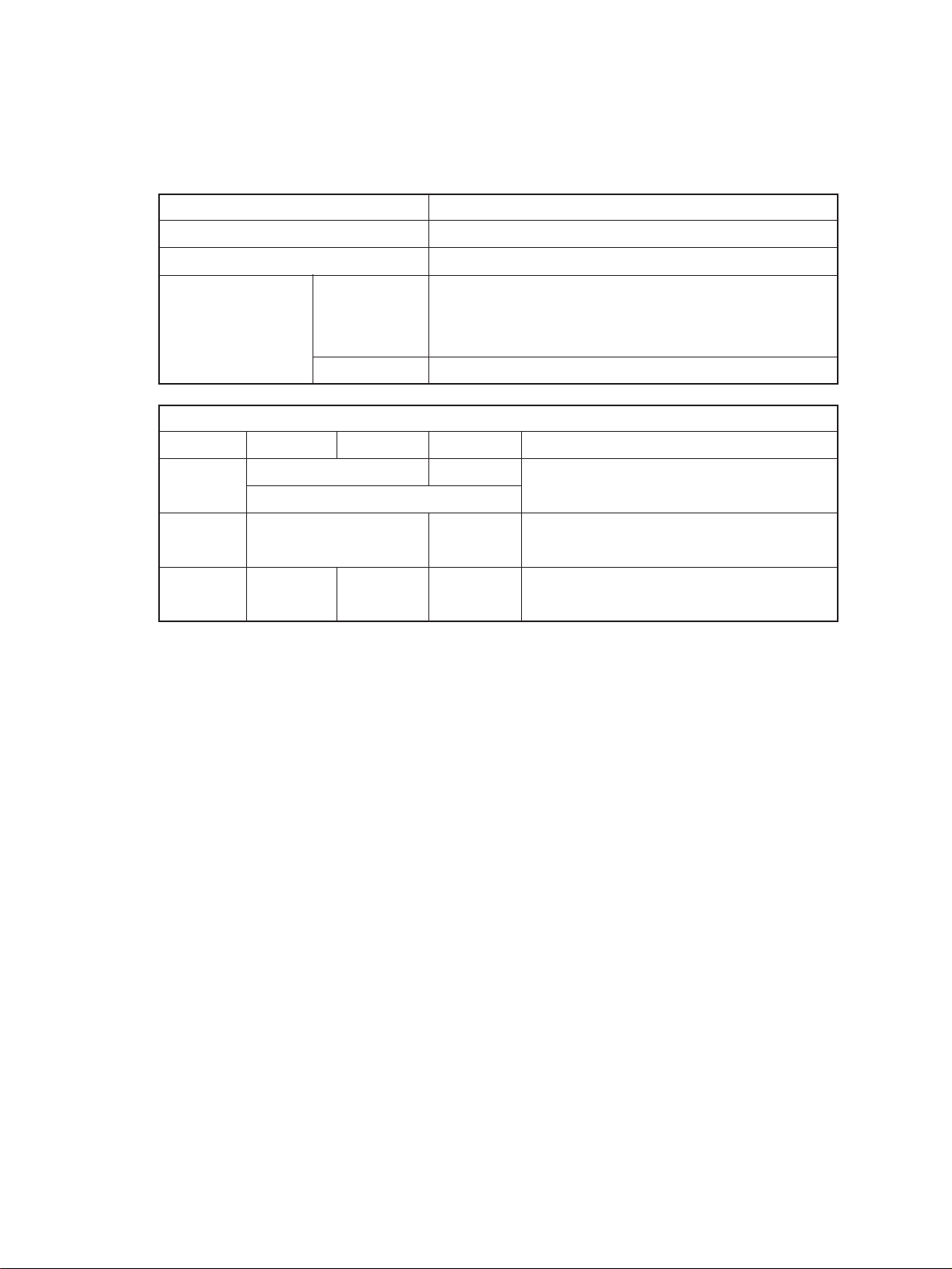
1.1 Specifications
Copy process Indirect electrophotographic process (dry)
Type Desk top (console when the pedestal is used)
Exposure Type Slit exposure with fixed table
Acceptable originals Kind Sheets, books, and 3-dimensional objects.
When the document feeder is used:
Sheet originals only (60 g/m2~90 g/m2) (16 lb.~24 lb.)
Maximum size A3 (Ledger)
Copy paper
Cassette Duplexing Manual Note
Size A3~A5-R A3~A6-R Adjustable to
(Ledger~Statement-R) Unfixed, Arbitary sizes
Thickness 64~80 64~130 Unit: g/m
(Weight) (17~22) (17~34) (Unit: lb.)
2
Special _ _ OHP film
paper etc.
Dec. 1996 © TOSHIBA 1 - 1 2060, 2860/70 SPECIFICATIONS
Page 5

Copy speed
System copy speed
Cassette/manual LCF
Paper size 2060 2860 2060 2860
A4, B5, A5-R 20 28 20 28
LT, ST-R
A4-R, B5-R 20 26 — —
LT-R
B4, FOLIO 20 22 — —
LG, Computer
A3 19 19 — —
LD
Reduction/ 15 15 15 15
Enlargement
Manual feeding represents the value when the size is set.
CPM
(BLI format)
Mode CPM
Original→Copy Number of copies 2060 2860
1 → 1 1 set 19 24
3 set 20 27
5 set 20 28
1 → 2 1 set 10 10
3 set 15 18
5 set 17 21
2 → 2 1 set 8 8
3 set 14 16
5 set 16 19
2 → 1 1 set 16 16
3 set 19 23
5 set 19 25
*Ten originals (A4) are set in the ADF. This includes the first
copy time.
First copy Approx. 4.0 sec. (Actual-size A4 or Letter from upper cassette)
Warm-up time Approx. 80 sec.
Multiple copying 1~999, keyboard entry
Reproduction ratio
Actual ratio 100% or 101% (Setting mode)
Zoom ratios 50~200% (Multiple reduction and enlargement in 1% steps)
2060, 2860/70 SPECIFICATIONS 1 - 2 Dec. 1996 © TOSHIBA
Page 6

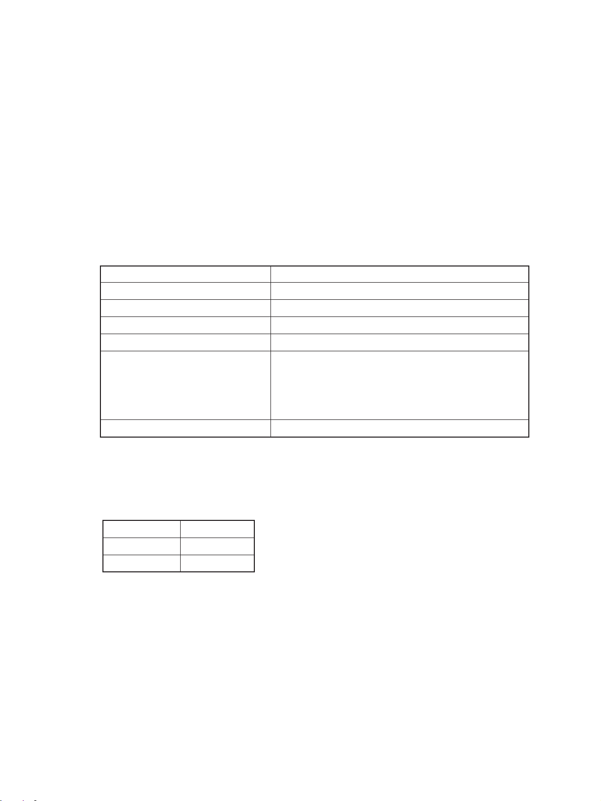
Paper supply Cassette or sheet-bypass feeding
Cassette: 600 sheets
Sheet-bypass feeding: 50 sheets
Toner supply Automatic density detection and replenishment
Toner cartridge replacement
Exposure Automatic control and manually selectable (9 steps)
Weight Copier: 73 kg (with 2 cassettes and the platen cover),
ADU: 10 kg
Power source 115 V ~ 60 Hz, 12A For the U.S.A. and Canada
220 V ~ 50/60 Hz, 8A
240 V ~ 50 Hz, 8A
Power consumption 1.5 kW (115 V), 1.7 kW (220 V/240 V)
Counter 6-digit total counter
Machine size
598mm
640mm
For Europe
123
540mm
Dec. 1996 © TOSHIBA 1 - 3 2060, 2860/70 SPECIFICATIONS
Page 7
1.2 Accessories
Copy receiving tray : 1 pc.
Operator’s manual : 1 pc.
Set-up report : 1 pc.
Drum : 1 pc.
Developer : 1 bottle
Toner : 1 pc.
*Accessories vary according to the destination.
1.3 Options
Automatic duplexing unit: ADU MD-5002
Automatic document feeder: ADF MR-3006 (RADF), MR-2008 (ADF)
Paper feed pedestal: PFP KD-1003 (1 cassette), KD-2009 (2 cassettes)
Paper feed unit MY-1006
Large capacity feeder: LCF MP-1501
Sorter MG-1003A (10 bins)
Key copy counter MU-8/MU-10 (6 digit)
*Options vary according to the destination.
1.4 Supplies
Drum OD-2060
Developer ZD-2060
Toner ZT-2060
MG-1004 (10 bins staple)
MG-2009 (20 bins)
MG-2010 (20 bins staple)
2060, 2860/70 SPECIFICATIONS 1 - 4 Dec. 1996 © TOSHIBA
Page 8
2. OUTLINE OF THE MACHINE
2.1 Sectional Views and Electrical Parts Location Diagram
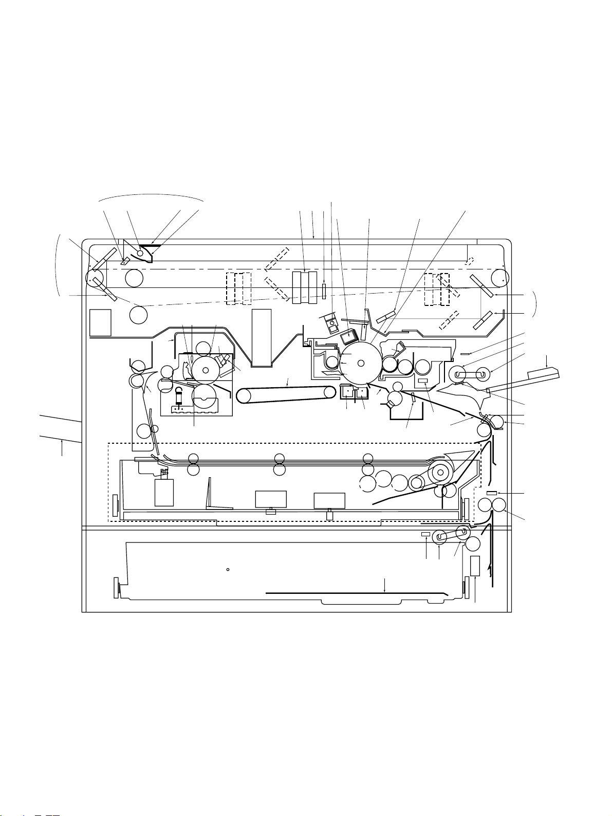
2.1.1 Sectional view
[A] Front view
6
BT
7
8
2
AQ
5
FR
FR
1
FQ
FK
ES
ES
4
EP ER
FT
3
EQ
EO
ENEM
EL
EK
GK
GT
CT
AO
AS
AP AN
AR BK AL
BL
BN
BM
BR
BO
BP
BQ
FS
BS
CL
CK
ET
DS
CN
DR
CO
CM
DP
AM
AT
AK
DO
CS
DT
CR
FL
DN
9
CP
FM
DQ
DK
DL
CQ
FO
DMFN
FP
(This diagram includes an installed ADU. Refer to Chapter 13 concerning the ADU.)
Dec. 1996 © TOSHIBA 2 - 1 2060, 2860/70 GENERAL
Page 9

No. Name
No. Name
1 Carriage 1
2 Mirror 1
3 Reflector
4 Light distribution adjustment plates
5 Exposure lamp
6 Carriage 2
7 Mirror 2
8 Mirror 3
9 Mirror unit
AT Mirror 4
AK Mirror 5
AL Mirror 6
AM Slit glass
AN Auto exposure sensor
AO Lens
AP Original glass
AQ Ozone filter
AR Main charger
CQ Cassette
CR Manual feed separation pad
CS Manual feed roller
DT Manual pickup roller
DK Cassette separation roller
DL Cassette feed roller
DM Cassette pickup roller
DN Upper transport roller
DO Manual feed switch (S6)
DP Paper guide
DQ Lower transport roller
DR Aligning switch (S8)
DS Aligning roller (U)
ET Aligning roller (L)
EK Thermistor-1 (THMS1)
EL Thermostat (THERMO)
EM Heater lamp
EN Heat roller (upper side)
AS Discharge lamp
BT Receiving tray
BK LED eraser array
BL Main blade
BM Recovery blade
BN Toner recovery auger
BO Separation claw (for drum)
BP Transfer charger
BQ Separation charger
BR Drum
BS Bias guide
CT Transport belt
CK Magnetic roller
CL Leveller (doctor)
CM Auto-toner sensor
CN Mixer 1
CO Mixer 2
CP Sheet bypass guide
EO Pressure roller (lower side)
EP Separation claw (for heat roller)
EQ Felt roller
ER Heat roller cleaning blade
ES Fuser exit roller
FT Scraper
FK Fuser cover
FL Paper stop switch-1 (S7)
FM Paper stop switch-2 (S16)
FN Paper-empty switch-2 (S14)
FO Cassette tray
FP Cassette size switch-2 (S15)
FQ Exit/ADU selection gate
FR Exit roller
FS ADU
GT Exit fan (M7)
GK Bottom fan (M8)
2060, 2860/70 GENERAL 2 - 2 Dec. 1996 © TOSHIBA
Page 10

[B] Rear side view
HP HO IO IP
GQ
HLGRHKHTHRITIK
HS
GS
IT
IM
IT
IN
HN
HQ
HM
CT
EN
GP
FRES
IL
IN
Dec. 1996 © TOSHIBA 2 - 3 2060, 2860/70 GENERAL
Page 11

No. Name
GP Scanning motor (M2)
GQ Carriage drive wire
GR Drum gear
GS Aligning clutch (CLT2)
HT Drum driving gear
HK Drum belt
HL Belt for dev-unit, ALGN-roller & paper feeding drive
HM Belt for fuser drive
HN Main motor (M1)
HO Lens motor (M3)
HP Mirror motor (M4)
HQ Thermistor-2 (THMS2)
HR Dev-unit drive gear
HS Aligning roller
IT Paper feed belt
IK Manual feed clutch (CLT4)
IL Transport roller clutch (CLT1)
IM Transport roller drive belt
IN Cassette feed clutch (CLT3, 5)
IO Optical fan (M6,12)
IP Document motor (M11)
2060, 2860/70 GENERAL 2 - 4 Dec. 1996 © TOSHIBA
Page 12

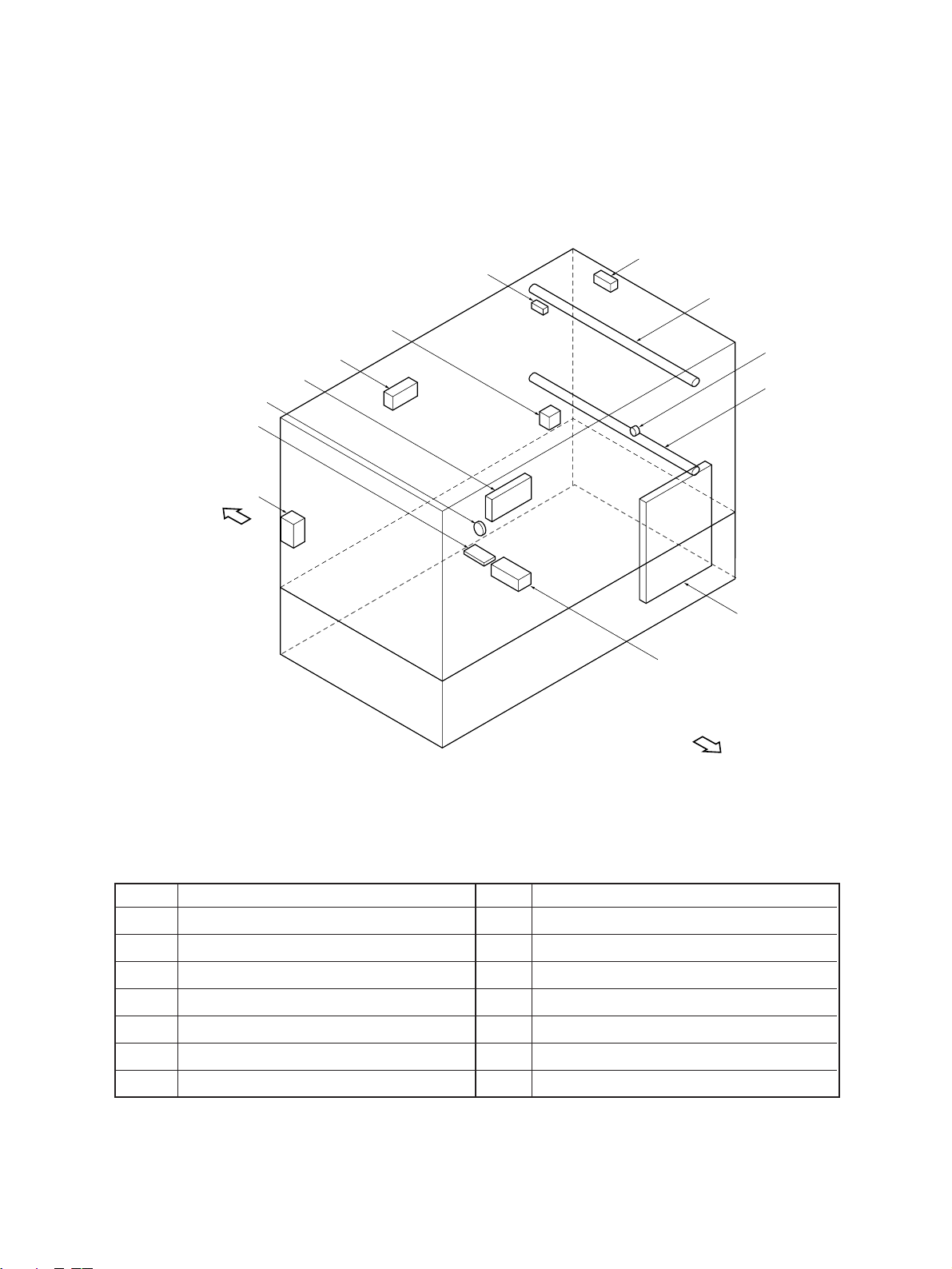
2.1.2 Electrical parts layout
[A] DC electrical parts (except motors)
[Front side]
1
BT
6
3
2
7
BO
8
AK
AL
BP
BN
AQ
AT
AS
AP
BK
CM
AR
CS
CP
CO
CT
DT
CK
CN
4
BQ
BL
BM
AN
AO
CQ
9
CR
AM
BS
5
CL
[Rear side]
Dec. 1996 © TOSHIBA 2 - 5 2060, 2860/70 GENERAL
Page 13

No. Name
No. Name
1 Control panel key PC board (PWA-KEY)
2 Display PC board (PWA-DSP)
3 Liquid crystal module (LCD)
4 Total counter (T-CTR)
5 Logic PC board (PWA-LGC)
6 Auto paper sensor-2 (APS-R)
7 Auto paper sensor-3 (APS-C)
8 Auto paper sensor-4 (APS-F)
9 Toner-full switch (T-FUL-SW) (S13)
*AT Size switch 1 (SIZE1-SW) (S5)
AK Discharge lamp PC board (PWA-ERS)
AL LED eraser array PC board (K-DCH)
AM High-voltage power supply (PS-HVT)
AN Home switch (HOME-SW) (S10)
AO Platen switch (PTN-SW) (S27)
AP Manual feed switch (M-FED-SW) (S6)
AQ Aligning switch (PSTPO-SW) (S8)
AR Paper stop switch 1 (PSTP1-SW) (S7)
*BK Paper-empty switch-1 (EMP1-SW) (S3)
BL Exit switch (EXIT-SW) (S9)
BM Heat-roller thermistor 1 (THMS1-HTR)
BN Toner sensor (TNR-ATC)
BO Lens switch (LNS-SW) (S11)
BP Mirror switch (MRR-SW) (S12)
BQ Automatic exposure PC board (PWA-AES)
BS Aligning-roller clutch (RGT0-CLT) (CLT2)
CT Transport-roller clutch (RGT1-CLT) (CLT1)
CK Manual-feed roller clutch (MFED-CLT) (CLT4)
*CL Feed-roller clutch 1 (FED1-CLT) (CLT3)
CM Size switch 2 (SIZE2-SW) (S15)
CN Feed-roller clutch 2 (FED2-CLT) (CLT5)
CO Paper-empty switch 2 (EMP2-SW) (S14)
CP Paper stop switch 2 (PSTP2-SW) (S16)
CQ Heat-roller thermistor-2 (THMS2-HTR)
CR Drum thermistor (DRM-THMS)
*CS Tray-up switch (T-UP1-SW) (S28)
AS Side door switch (U-COV-SW) (S4)
BT Auto paper sensor-1 (APS-3B)
*: Option
DT Tray-up switch (T-UP2-SW) (S29)
2060, 2860/70 GENERAL 2 - 6 Dec. 1996 © TOSHIBA
Page 14

[B] DC electrical parts (motors)
EK
DO
[Front side]
DS
DP
DL
ET
EL
No. Name
DK Main motor (MAIN-MOT) (M1)
DL Scanning motor (SCN-MOT) (M2)
DM Lens motor (LNS-MOT) (M3)
DN Mirror motor (MRR-MOT) (M4)
DO Toner motor (TNR-MOT) (M9)
DP Document motor (DCM-MOT) (M11)
DK
DM
DN
DQ
DR
[Rear side]
No. Name
*DQ Tray-up motor-1 (T-UP1-MOT) (M13)
DR Tray-up motor-2 (T-UP2-MOT) (M14)
DS Optical fan-F (OPT-FAN-F) (M12)
ET Optical fan-R (OPT-FAN-R) (M6)
EK Exit fan (EXIT-FAN) (M7)
EL Bottom fan (BTM-FAN) (M8)
*: Option
Dec. 1996 © TOSHIBA 2 - 7 2060, 2860/70 GENERAL
Page 15
[C] AC electrical parts
[Front side]
FM
EN
FK
EP
FT
FN
EO
FO
FL
ES
EQ
EM
ER
[Rear side]
No. Name
EM SW power supply (PS-ACC)
EN Door switch (DOOR-SW) (S2)
EO Main switch (MAIN-SW) (S1)
EP Lamp regulator PC board (PWA-LRG)
EQ Heater lamp (HTR-LAMP)
ER Damp heater L (D-HTR-L) (Option)
No. Name
FT Thermostat (Option)
FK Damp heater U1 (D-HTR-U1) (Option)
FL Exposure lamp (EXPO-LAMP)
FM Thermofuse (FU-EXPO)
FN Fuse PC board (PWA-FUS) (Option)
FO Damp heater U2 (D-HTR-U2) (Option)
ES Thermostat (K-THERMO)
2060, 2860/70 GENERAL 2 - 8 Dec. 1996 © TOSHIBA
Page 16

2.2 Symbol and Function of Electrical Parts
(1) Motors
Symbol
M1 MAIN-MOT (Main motor) Drives the drum, developer, IC motor 10 31
M2 SCN-MOT (Scanning motor) Scans the optical system Pulse motor 5 23
M3 LNS-MOT (Lens motor) Drives the lens unit Pulse motor 11 23
M4 MRR-MOT (Mirror motor) Drives the mirror unit Pulse motor 11 23
M6 OPT-FAN-R (Optics fan-R) Cools the optical system IC motor: Z80 5 8
M7 EXIT-FAN (Exit-fan) Cools the drum and cleaner IC motor: Z80 4 14
M8 BTM-FAN (Bottom fan) Prevents the paper from floating IC motor: Z80 4 14
M9 TNR-MOT (Toner motor) Replenishes the toner Brush motor 23 30
M11 DCM-MOT (Document motor) Drives copy-area indicators Pulse motor 9 2
M12 OPT-FAN-F (Optical fan-F) Cools the optical system IC motor: Z80 4 14
M13 T-UP1-MOT (Tray-up motor-1) Drives the upper cassette tray to Brush motor 12 36
Code name Remarks
heat roller and transport belt
up through suction
lift up/down
Function
Parts list
Page Item
M14 T-UP2-MOT (Tray-up motor-2) Drives the lower cassette tray to Brush motor 12 36
lift up/down
(2) Electromagnetic spring clutches
Parts list
Symbol
CLT1 RGT1-CLT Transmits transport-roller drive. 13 40
(Transport-roller clutch)
CLT2 RGT0-CLT Transmits aligning-roller drive. 15 16
(Aligning-roller clutch)
CLT3 FED1-CLT Transmits feed-roller clutch 12 24
(Feed-roller clutch-1) drive. (Upper cassette)
CLT4 MFED-CLT Transmits manual-feed roller 14 17
(Manual-feed roller clutch) clutch drive.
CLT5 FED2-CLT Transmits feed-roller clutch 12 24
(Feed-roller clutch-2) drive. (Lower cassette)
Code name Function Remarks
Page Item
(3) Counters
Parts list
Symbol Code name
T T-CTR (Total counter) Total counter 6-digit 3 23
K K-CTR (Key-copy counter) Individual counter 6-digit (option) 101 5
Dec. 1996 © TOSHIBA 2 - 9 2060, 2860/70 GENERAL
Function
Remarks
Page Item
Page 17

(4) Switches
Parts list
Symbol
S1 MAIN-SW (Main switch) Power supply Tumbler type 6 3
S2 DOOR-SW (Door switch) For safety, cancels abnormal Push switch 6 4
S3 EMP1-SW Detects lack of paper in the upper Photointerruptor 12 32
S4 U-COV-SW For safety, detects open/closed Push switch 2 27
Code name
condition
(Paper-empty switch-1) cassette
Function
Remarks
Page Item
(Side door switch)
S5 SIZE1-SW (Size switch-1) Detects upper cassette size Push switch 13 50
S6 M-FED-SW Detects manual feeding Photointerruptor 14 3
(Manual-feed switch)
S7 PSTP1-SW Detects paper in front of the Photointerruptor 13 8
(Paper stop switch-1) upper transport roller
S8 PSTP0-SW Detects paper in front of the Photointerruptor 15 20
(Aligning switch) aligning roller
S9 EXIT-SW (Exit switch) Detects exiting paper Photointerruptor 28 8
S10 HOME-SW (Home switch) Detects home position of the Photointerruptor 11 8
S11 LNS-SW (Lens switch) Detects home position of the lens Photointerruptor 11 8
S12 MRR-SW (Mirror switch) Detects home position of the mirror Photointerruptor 11 8
S13 T-FUL-SW Detects when the used toner bag Push switch 10 25
(Toner-full switch) is full
S14 EMP2-SW Detects lack of paper in the lower Photointerruptor 12 32
condition of paper jam release cover
optical system
unit
unit
(Paper-empty switch-2) cassette
S15 SIZE2-SW Detects lower cassette size Push switch 13 50
(Size switch-2)
S16 PSTP2-SW Detects paper in front of the lower Photointerruptor 2 26
(Paper stop switch-2) transport roller
S27 PTN-SW Detects open/closed condition of Photointerruptor 5 38
(Platen switch) the platen cover
S28 T-UP1-SW Detects the position of the upper Photointerruptor 12 32
(Tray-up-1 switch) cassette tray
S29 T-UP2-SW Detects the position of the lower Photointerruptor 12 32
(Tray-up-2 switch) cassette tray
2060, 2860/70 GENERAL 2 - 10 Dec. 1996 © TOSHIBA
Page 18

(5) Heaters and lamps
Parts list
Symbol
EXP EXPO-LAMP Exposes the original Halogen lamp 18 13
HTR HTR-LAMP (Heater lamp) Fixing Halogen lamp 25 6
ERS ERS-LAMP Discharges the drum Fuse type 4 12
DCH DCH-LED To interrupt the charge LED 4 10
DHU1
Code name
(Exposure lamp) 300W
(Discharge lamp)
(LED eraser array)
D-HTR-U1 (Damp heater U1) Keeps optical system warm (option)
Function
Remarks
900W
(100V series)
1100W
(200V series)
Cement resistor 102 4
Page Item
DHU2
DHL D-HTR-L (Damp heater L)
D-HTR-U2 (Damp heater U2) Keeps optical system warm (option)
Keeps the drum and transfer/separation
charger case warm (option)
Cement resistor 102 4
Cement resistor 7 30
(6) PC boards
Symbol
LGC PWA-LGC (Logic PC board) Controls the entire copier 8 15
DSP PWA-DSP Controls condition displays 3 20
(Display PC board)
KEY PWA-KEY Controls operation keys 3 21
(Key PC board)
LRG PWA-LRG Controls exposure lamp 5 20
(Lamp regulator PC board)
DCH K-DCH Turns on and drives LED during 4 10
(LED eraser array PC board) reduction
ERS PWA-ERS Discharge lamp 4 12
Code name
Function
Remarks
Parts list
Page Item
(Discharge lamp PC board)
AES PWA-AES Reads dark/light of the original 17 37
(Automatic exposure PC board)
FUS PWA-FUS (Fuse PC board) Fuse for the damp heater circuit 7 31
Dec. 1996 © TOSHIBA 2 - 11 2060, 2860/70 GENERAL
Page 19

(7) Transformers
Parts list
Symbol
HVT PS-HVT (Charging transformer) Generates high voltage electricity
ACC PS-ACC Power supply for whole copier 8 7
(Power supply for all) power
Code name
for charging (negative voltage)
(Transfer/separation Generates high voltage electricity
transformer) for transfer/separation and
developing bias voltage
(Transfer bias Generates bias voltage to raise
transformer) transfer efficiency
Function
Remarks
Mono unit type 7 27
Page Item
(8) Others
Parts list
Symbol
ATS SNR-ATC Reads toner density with a magnetic 23 33
Code name
Function
Remarks
Page Item
(Auto-toner sensor) sensor
THMS1 THMS1-HTR Detects temperature of the heat roller 26 19
(Heat-roller thermistor-1)
THMS2 THMS2-HTR Detects the temperature of the heat roller 26 27
(Heat-roller thermistor-2) end
THERMO K-THERMO Prevents abnormal heating of heat roller 26 8
(Thermostat)
FU FU-EXPO (Thermofuse) Prevents abnormal heating of the 18 12
exposure lamp
2060, 2860/70 GENERAL 2 - 12 Dec. 1996 © TOSHIBA
Page 20
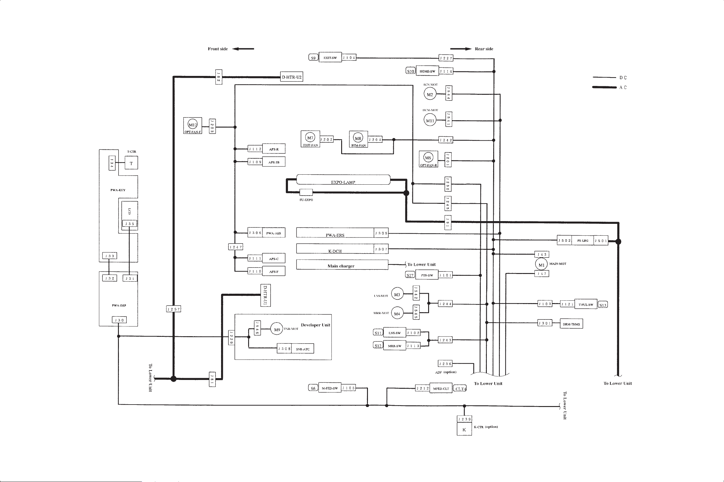
2.3 Wire Harness Location Diagram
[A] Location diagram for upper unit
Dec. 1996 © TOSHIBA 2 - 13 2060, 2860/70 GENERAL
Page 21

[B] Location diagram for lower unit
2060, 2860/70 GENERAL 2 - 14 Dec. 1996 © TOSHIBA
Page 22
Return
3560/70 S/M
Skip
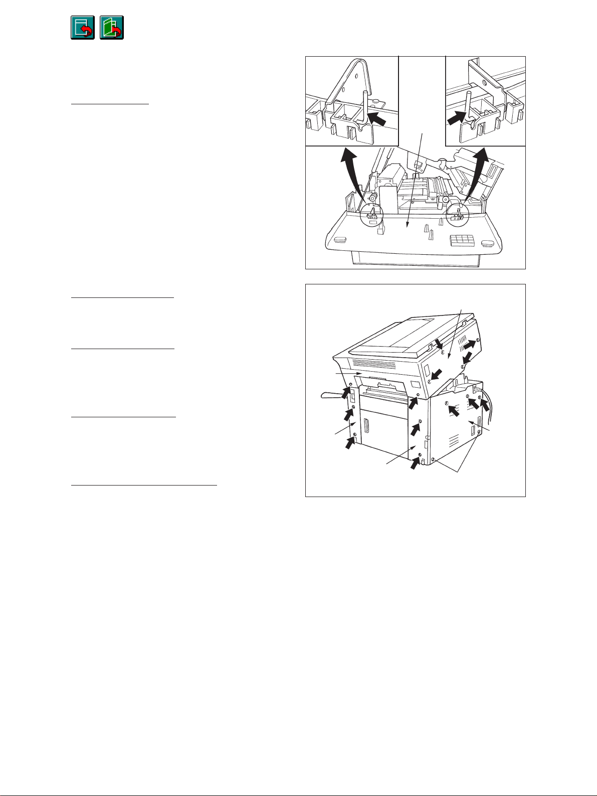
2.4 Removal of Co vers and PC Boards
2.4.1 Removal of covers
[A] Front cover
(1) Open the front cover.
(2) Remove the pins on the hinges at both ends
(1 each).
[B] Upper rear cover
(1) Remove the 4 screws.
[C] Lower rear cover
(1) Remove the upper 3 screws.
(2) Loosen the lower 2 screws.
Front cover
Upper rear cover
Upper
feed
cover
[D] Upper feed cover
(1) Open the front cover and the bypass tray and
then remove the 2 screws.
[E] Feed cover (left and right)
(1) Remove the paper feed cover.
(2) When removing the left feed cover, open the
front cover.
(3) Remove the screws (2 on each side).
Left
feed
cover
Right feed cover
Lower
rear
cover
Loosen
Dec. 1996 © TOSHIBA 2 - 15 2060, 2860/70 GENERAL
Page 23
Return
3560/70 S/M
Skip
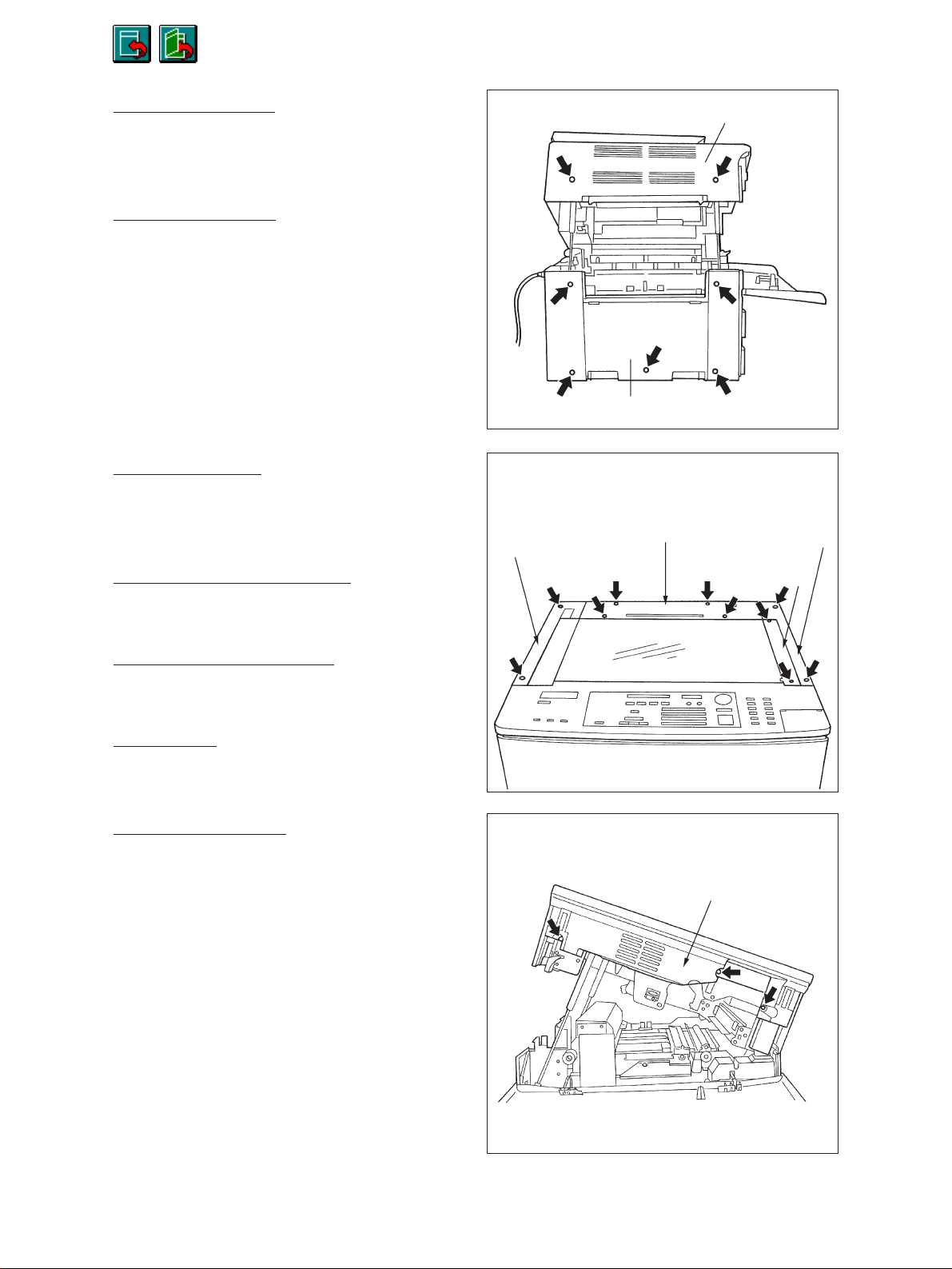
[F] Upper exit cover
(1) Remove the 2 screws.
(2) Open the front cover and remove the screw.
[G] Lower exit cover
(1) Lift the upper unit.
(2) Remove the 5 screws.
[H] Rear top cover
(1) Remove the original cover.
(2) Remove the 4 screws.
Left top cover
Upper exit cover
Lower exit cover
Rear top cover
Right top cover
[I] Right top cover (feed side)
(1) Remove the 2 screws.
[J] Left top cover (exit side)
(1) Remove the 2 screws.
[K] Glass fix
(1) Remove the 2 screws.
[L] Upper inner cover
(1) Remove the process unit.
(2) Remove the 3 screws.
Glass fix
Upper inner cover
2060, 2860/70 GENERAL 2 - 16 Dec. 1996 © TOSHIBA
Page 24

Return
3560/70 S/M
Skip
[M] Middle inner cover
(1) Remove the screw.
[N] Door switch cover
(1) Remove the 2 screws.
Middle inner cover
Door switch cover
[O] Lower inner cover
(1) Remove the toner box.
(2) Remove the middle inner cover.
Lower inner cover
(3) Remove the 1 screw.
Dec. 1996 © TOSHIBA 2 - 17 2060, 2860/70 GENERAL
Page 25

Return
3560/70 S/M
Skip
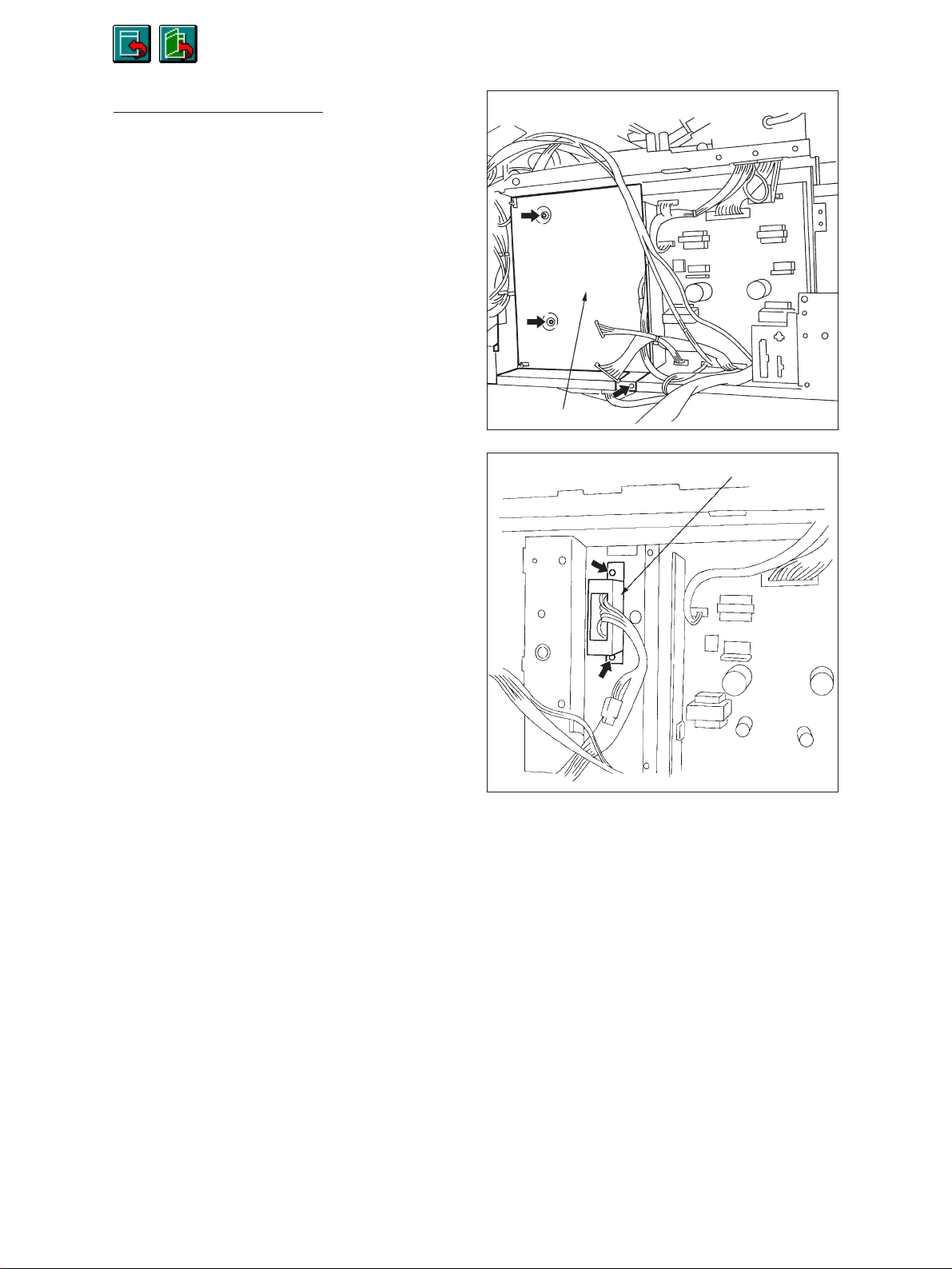
2.4.2 Removal of main PC boards
[A] Logic PC board (PWA-LGC)
(1) Remove the lower rear cover.
(2) Remove the 16 connectors (2860).
(15 connectors for 2060).
(3) Remove the lock supports (4 pcs.)
(4) Remove the logic PC board.
[B] Power supply PC board (PS-ACC)
(1) Remove the connector bracket (2 screws).
(2) Remove the 14 connectors.
(3) Remove the 4 screws.
(4) Remove the power supply PC board.
[C] Lamp regulator PC board (PWA-LRG)
(1) Remove the upper rear cover.
(2) Remove the 2 connectors.
Lock support
Lock support
PWA-LGC
PWA-LRG
Lock support
PS-ACC
Connector bracket
(3) Remove the lamp regulator PC board (4 lock
supports).
Connectors
2060, 2860/70 GENERAL 2 - 18 Dec. 1996 © TOSHIBA
Lock support
Page 26
Return
3560/70 S/M
Skip
[D] ADU drawer connector
(1) Remove the logic PC board.
(2) Remove the bracket for the logic PC board (3
screws).
Remove the connector J535 on the PS-ACC.
(3) Remove the bracket for the ADU drawer con-
nector (2 screws).
Bracket for PWA-LGC
ADU drawer connector bracket
Dec. 1996 © TOSHIBA 2 - 19 2060, 2860/70 GENERAL
Page 27

Return
Skip
3560/70 S/M
3. COPYING PROCESS
3.1 Copying Process
Original exposure
2
Halogen lamp
Paper exiting
300 W
7
Fixing
Heat roller
900 W (115V)
1030W (220/240V)
9
8
LED eraser array
63 LEDs
Charging
1
–635V ±5 V
Discharge lamp
1.8W x 9 lamps
Cleaning
Separation
AC 3.41 kV
1 kHz
Optical
section
_
_
+
+
+
_
_
+
+
Transfer
–DC 5.25 kV
5
6
Toner
Carrier
_
_
+
_
+
_
+
3
Black development
Magnetic roller
Bias –100 VDC
Sheet-bypass feeding
(50 sheets)
Cassette feeding (upper/
lower/PFP)(600 sheets)
LCF feeding
(1500 sheets)
4
Transfer bias
1 Charging :Negatively charges surface of
D
the photosensitive drum.
2 Exposure : Forms an electrical image on
D
the drum.
3 Development : toner adheres to surface of
D
photosensitive drum and forms
a visible image.
4 Transfer bias :Increases transfer efficiency.
D
5 Transfer :Transfers the visible image from
the drum onto the transfer
(copy) sheet.
–DC 990 V
6 Separation : Separates the transfer sheet,
along with the toner, from the
D
drum.
7 Fixing :Fixes the toner on the transfer
sheet by applying heat and
D
pressure.
8 Cleaning :Mechanically removes any re-
D
9
Discharge lamp
maining toner on the drum.
:Discharges any remaining
charge from the drum.
Dec. 1996 © TOSHIBA 3 - 1 2060, 2860/70 PROCESS
Page 28

Return
3560/70 S/M
Skip
3.2 Comparison with the 2050 of Copying Process Conditions
Process 2050 2060/2860
1. Drum OD-1710 (OPC ø60) OD-2060 (OPC ø60)
(1) Sensitivity Highly sensitized drum (1)
(2) Charger grid voltage DC –800V (2)–635 V DC
Scolotron system Scolotron system
Output adjustable by using the
ten keys
2. Main charger Variable output (fixed current) using
the digital keys
3. Exposure
(1) Light control Automatic exposure/manual (1)Automatic exposure and
slide volume setting manual 9-step setting
(2) Light source 300W halogen lamp stabilized with (2)
regulator (light intensity remains
constant even when voltage varies)
4. Development
(1) Magnetic roller One magnetic roller (with two shaft (1)
mixers)
(2) Auto-toner Magnetic bridge-circuit system (2)
(3) Toner replenishment Toner cartridge system (3)
(4) Toner-empty detection Intensity sensing system (4)
(5) Toner T-1710 (Black) (5)T-2060 (Black)
T-1710-R (Red)
T-1710-BL (Blue)
(6) Developing material D-1710 (Black) (6)D-2060 (Black)
D-1710-R (Red)
D-1710-BL (Blue)
(7) Developer bias –194V DC, volume adjustable (7)–100 V DC, adjustable using the
digital keys
5. Transfer bias –1.4KV DC –990 V DC
6. Transfer Adjustable output (fixed current) using
the digital keys
7. Separation Adjustable output (independently
adjustable using the digital keys)
2060, 2860/70 PROCESS 3 - 2 Dec. 1996 © TOSHIBA
Page 29

Return
Skip
3560/70 S/M
Process 2050 2060/2860
8. Discharge
(1) Discharging position Discharge by exposure after cleaning (1)
(2) Discharge lamp Discharge by tungsten lamp (2)
9. Cleaning
(1) System Blade system (1)
(2) Recovered toner Non-reusable (2)
10. Fixing
(1) System Long-life heat roller system (1)
• Fixing • Fixing roller: Teflon coated roller • Fixing roller:
Aluminum roller coated with
Teflon (ø40)
• Pressure • Pressure roller: PFA tube silicon • Pressure roller:
roller (ø28) Silicon rubber roller with
PFA tube. (ø35)
• Lamp rating Infrared heat Infrared heat
• 900W (100V series) • 900W (115V)
• 1100W (200V series) • 1030W (220/240V)
(2) Cleaning Cleaning with silicon impregnated (2)
roller
(3) Heater-temperature control ON/OFF control by thermistor (3)
11. Control Microcomputer
Dec. 1996 © TOSHIBA 3 - 3 2060, 2860/70 PROCESS
Page 30

Return
3560/70 S/M
Skip
4. COPIER OPERATION
4.1 Operation Outline
Copier operation Operation during warm up and standby
Automatic-feed copying using PRINT key
Copying operation Bypass-feed copying
Interrupt copying
4.2 Description of Operation
4.2.1 Operation up to standby state after power on
(1) Initial operation
• The main switch is turned ON.
• Copy quantity indicator “0” and “WAIT WARMING UP” are displayed.
• Initialization of the optical system
~ Carriages move to their home position and then stop.
~ Lens and mirror units move to their home position and then stop.
~ Indicators perform the initial operation and move to a position indicating the copy area.
• Initialization of the paper feed section
~ Each slot’s cassette trays move upward. If they were raised already, they are not moved.
(2) Pre-running
65 sec. have elapsed since the power was turned ON ~
Main motor rotates ~ Fuser unit drive section rotates: Pre-running
Pressure roller is warmed
After pre-running for 15 sec., the main motor stops
~ Fuser unit drive section stops
(3) When the heat roller temperature is sufficient for fixing, the heater lamp is turned off , and the copier
enters the standby mode.
4.2.2 Standby (ready)
• Bottom fan motor (M8) and exit fan motor (M7) are running at low speed.
• All keys on the control panel are operable.
When there is no key input for a set amount of time, the copy quantity “1” will be shown, the
reproduction ratio will indicate “actual size”, and the exposure will be set at automatic.
Dec. 1996 © TOSHIBA 4 - 1 2060, 2860/70 OPERATION
Page 31

Return
3560/70 S/M
Skip
4.2.3 Automatic feed copying using the PRINT key
(1) PRINT key is pressed
• Main, transfer, and separation chargers, transfer bias, discharge lamp and LED eraser array are
turned on.
• Optical fan motor (M6, M12), bottom fan motor (M8) and exit fan motor (M7) are running at high
speed.
• Main motor is turned on
~ Drum, developer unit, transport belt, heat roller, and exit roller are running.
(2) Cassette feeding
• Feed clutch (CLT3 or 5) is turned on
~ Pick-up roller, paper feed roller, and separation roller are running.
– Transpor t roller rotating
• Paper reaches the transport roller
~ Paper stop switch-2 (S14) is turned on. After a set amount of time , the feed clutch (CLT3 or 5) is
turned off.
* Paper reaches the aligning roller. Paper stop switch-1 (S7) is turned on.
~ Aligning operation
After a set amount of time, the feed roller stops rotating (CLT1).
(3) Carriage operation
• Exposure lamp is turned on.
Carriages -1 and -2 scan in a forward direction
~ Scanning motor (M15) is turned on. At this time , if the toner density of the de v eloper material is
lower than the set value, the copier enters the toner supply operation.
~ Toner motor (M9) is turned ON.
(4) A set time lag after the carriage operation;
aligning clutch (CLT2) is turned on:
~ paper is sent to the transfer unit.
The counter is increased by 1.
(5) Termination of carriage scanning.
• Scanning motor (M2) is turned off.
• Main charger and exposure lamp are turned off.
• Aligning clutch (CLT2) is turned off. (Timing of shutting off depends on paper size.)
(6) Exit operation
• Exit switch (S9) detects the passing of the paper trailing edge.
• Main motor (M1), transfer and separation chargers, transfer bias, discharge lamp, and LED
eraser array are turned off.
• Optical fan motor (M6, M12) stop, and bottom fan motor (M8) and exit fan motor (M7) are running
at low speed.
• Carriages and indicators move to the position indicating copy area.
• The copier enters the standby mode.
2060, 2860/70 OPERATION 4 - 2 Dec. 1996 © TOSHIBA
Page 32

Dec. 1996 © TOSHIBA 4 - 3 2060, 2860/70 OPERATION
Return
Skip
3560/70 S/M
MAIN-MOT
SCN
RGT
EXIT-SW
EXPO
HVT-M
Transfer
OFF
0.1
0.1
FWD
0.72
1.02 2.12 3.95 5.05
ON ON
0.44 2.13 3.37
ON ON
0.71
ON
1.37
BWDBWD
ON
2.03
2.35 4.10
2.10
High
OFF
CW
4.913.772.411.990.840.2
3.64 4.96
ON
BWDFWD
5.06
5.034.30
5.29
High
5.34
7.10 8.50 8.53
CCW
5.753.932.82
ON
OFF
6.85
Separation
Guide bias
OFF 0.1
1.47
2.46
4.10
High
4.40
ONON
Timing chart for two A4 actual-size cassette feeding
5.40
5.224.142.291.20
LOWLOW
Page 33

Return
3560/70 S/M
Skip
4.2.4 Bypass-feed copying
(1) A sheet of paper is inserted through the bypass guide
• Manual feed switch (S6) is turned on.
(2) PRINT key is pressed
• The main transfer and separation chargers, transfer bias, discharge lamp, and LED eraser array
are turned on.
• Optical fan motor (M6, M12), bottom fan motor (M8) and exit fan motor (M7) are running at high
speed.
• Main motor (M1) is turned on
~ Drum, developer unit, transport belt, heat roller, and exit roller are running.
(3) Sheet-bypass feeding
• Manual feed clutch (CLT4) is turned on
~ Manual feed roller is lowered.
~ Manual feed roller, paper feed roller, and separation roller are running.
– Aligning operation –
• Paper reaches aligning roller
~ Paper stop switch1 (S7) is turned on.
After a set time lag, the manual feed clutch (CLT4) is turned off and paper feeding is terminated.
(4) Same as operation (3) through (6) of “4.2.3 Automatic Feed Copying Using the PRINT key”.
4.2.5 Interrupt copying
(1) The INTERRUPT key is pressed.
• Interruption LED is turned on.
The copying operation is temporarily halted and carriages-1 and -2 return to their home position.
The copying mode is set to automatic exposure and 1-to-1 reproduction ratio. Register remains
unchanged.
(2) The preferred copying modes are specified.
(3) After interrupt copying is terminated when the INTERRUPT key is pressed again, the interrupt LED
goes off and the copier returns to the conditions before the interruption.
(4) PRINT key is pressed
The copying operation before the interruption is resumed.
2060, 2860/70 OPERATION 4 - 4 Dec. 1996 © TOSHIBA
Page 34

Return
3560/70 S/M
Skip
4.3 Fault Detection
If a fault occurs in the copier , a symbol corresponding to the type of fault will be displa yed in order to dr aw
the attention of the operator.
• Classification of faults
A) Faults which can be cleared without turning off the door switch (yellow flashing display on the
display panel).
(1) ADD PAPER
(2) BYPASS MISFEED
(3) INSERT KEY COPY COUNTER
(4) CASSETTE MISFEED
B) Faults which cannot be cleared without turning off the door switch (red flashing display on the
display panel).
(1) CLEAR PAPER
(2) ADD TONER (yellow flashing display)
(3) REPLACE TONER BAG
C) Faults which cannot be cleared unless the main switch (S1) is turned off.
(1) SERVICE CALL
A-1) ADD PAPER ( )
[In the case of the copier and PFP cassettes]
• When the cassette is not installed, the size switch (S5 or S15) detects the absence of the
cassette.
G
When the cassette is not installed.
When the cassette is installed but
there is no paper in the cassette.
6
4
7
4
8
~Size switches are all switched off.
Paper empty status.
ff
Signal sent to control circuit.
The ADD PAPER display will flash.
* The PRINT key will not function.
Dec. 1996 © TOSHIBA 4 - 5 2060, 2860/70 OPERATION
Page 35

Return
3560/70 S/M
Skip
[In the case of the LCF and the pedestal]
By combining the operation of the tray motor and the condition of the tray-up switch and the empty
switch, the CPU detects whether or not there is paper.
• When the power is turned on or when the LCF door is opened/closed (for the pedestal:
when the power is turned on or when the cassette is removed) ~
The PFC (Paper Feed Controller) causes the LCF to initialize.
ff
Detects whether or not there is paper
• Tray motor comes on ~ The tray rises.
f
At this time, both tray-up and LCF empty switches are off.
• A fixed time later, if the tray-up switch is not turned on:
The tray is
not normal
→
The “ADD PAPER” is displayed regardless of paper being present or not.
↕
Removing/reinstalling the LCF or turning off/on clears this condition. (For the pedestal, turn
off/on the power.)
f
• Within a fixed time, the tray-up switch turns on:
~ The tray motor stops.
At this time, if the empty switch is on ~ It is determined there is paper.
At this time, if the empty switch is off ~ It is determined there is no paper.
f
The “ADD PAPER” is displayed.
• During copying, sheets of paper are fed and when the paper supply becomes low →
The tray-up switch goes off → The PFC turns on the tray motor ~ The tray moves up.
The tray-up switch come on → The tray motor stops.
• During copying, when the empty switch goes off despite the tray-up switch being on
fff
It is determined there is no paper.
“ADD PAPER” is displayed.
Copying stops.
2060, 2860/70 OPERATION 4 - 6 Dec. 1996 © TOSHIBA
Page 36

Return
3560/70 S/M
Skip
A-2) BYPASS MISFEED ( )
• During sheet bypass copying
14443
The manual feed clutch (CLT4) has been tur ned on
f
The paper-stop switch-1 (S7) comes on
* If the paper-stop switch-1 (S7) does not come on within the specified time:
fff f
BYPASS MISFEED
The BYPASS MISFEED symbol is displayed
Copying cannot be started
Clearing method: Remove the paper from the sheet-bypass guide. The manual-f eed switch
(S6) goes off.
A-3) INSERT KEY COPY COUNTER ( )
• If the copy counter (optional) is installed in the copier and is then withdrawn:
The INSERT KEY COPY COUNTER display appears
f
Copying is not possible
• If the counter is withdrawn during copying, the machine will stop after the paper being copied
has exited.
B-1) CLEAR PAPER ( )
• Leading-edge jam detection by the exit switch (S9): (E01)
The aligning clutch (CLT2) is turned on
ff
1.875 sec.*
The exit switch (S9) comes on
* When the exit switch (S9) has not come
on after 1.875 seconds have elapsed.
The CLEAR PAPER symbol (E01) appears and copying will stop.
f
Aligning motor
Exit switch
Timer
On
On
0
1.875 sec
CLEAR PAPER (E01)
Dec. 1996 © TOSHIBA 4 - 7 2060, 2860/70 OPERATION
Page 37

Return
3560/70 S/M
Skip
•
• Immediately after power on
T railing-edge detection b y exit switch (S9): (E02)
Aligning clutch (CLT2) goes off.
↓ 1.92 sec*
The exit switch (S9) goes off (detects paper exit)
* When the exit switch (S9) does not go
off even after 1.92 seconds:
↓
The CLEAR P APER symbol appears (E02),
and copying stops.
↓
Exit switch (S9) is detecting paper (on)
↓
Aligning motor
Exit switch
Timer
Off
On
0
CLEAR PAPER (E02)
1.92 sec
CLEAR PAPER (E03)
• If the front cover is opened during copying
↓
CLEAR PAPER (E04)
• Leading edge jam detection by the paper stop switch in front of the aligning roller:
After the leading edge of the paper passes the transport rollers, if the paper stop switch-1 (S7)
is not turned on within a fixed time
↓
Paper misfeeding (E05)
• During paper feeding from the ADU:
After the feed clutch is turned on, if the paper stop switch (S16) does not come on within a
fixed time.
↓
Paper misfeeding (E11)
• During paper stacking in the ADU:
If the ADU jam switch (SA4) does not detect any paper at the fixed timing
↓
Paper misfeeding (E08)
2060, 2860/70 OPERATION 4 - 8 Dec. 1996 © TOSHIBA
Page 38

Return
3560/70 S/M
Skip
• During paper feeding from the copier and the pedestal:
After the feed clutch is turned on, if paper stop switches (S7/S16) do not come on within a fixed
time
↓
Paper misfeeding (E13 – E19)
E13 – E19: The error code is different according to the cassette used.
B-2) ADD T ONER ( )
Toner density has become low
↓
Toner empty detection: Auto-toner sensor
↓
Control circuit: f the ADD TONER symbol appears: copying is not possible
Clearing method: Replace the toner cartridge and close the front cover.
Toner supply operation: copying is possible
B-3) REPLACE TONER BAG ( )
The toner bag becomes full of toner
↓
The toner-recovery auger moves towards the rear of the copier: toner-full switch (S13) will be
turned on.
↓
REPLACE TONER BAG display
• When the toner-full switch (S13) comes on during copying
↓
Copying will stop after the last sheet has exited during copying
Clearing method: Replace with a new toner bag.
C-1) Service call
If the CLEAR/STOP key and the “8” key are pressed simultaneously when the SERVICE CALL symbol
symbol is flashing, one of the error codes will appear on the message display.
For the contents of the error codes, refer to the “SERVICE HANDBOOK”.
Dec. 1996 © TOSHIBA 4 - 9 2060, 2860/70 OPERATION
Page 39

Return
Skip
3560/70 S/M
4.4 Flow Charts
4.4.1 Power on to ready
Restart
Main switch on
DC power on
YES
Cover open?
NO
Heater lamp HTR ON
• SCN-MOT
• LNS-MOT
• MRR-MOT
• DCM-MOT
• STOP-MOT
• GUIDE-MOT
P-STP-SW
ON?
Start initialization
1444442444443
YES
NO
EXIT-SW ON?
NO
ADU-JAM-SW
YES
YES
ON?
NO
Paper jam
"E03"
A
2060, 2860/70 OPERATION 4 - 10 Dec. 1996 © TOSHIBA
Page 40

Return
Skip
3560/70 S/M
NO
A
T-FUL-SW
ON?
NO
Toner empty?
YES
Toner replen-
ishment
Initialization
over?
NO
YES
NO
Main motor
6 sec. ON
T-FULL SW
ON
(Toner-full removal
operation)
YES
Toner bag
replacement
NO
Have 20 sec.
passed since start
of initialization?
YES
Service call
“C21”or “C22” or “C23”
YES
• Lens and mirrors positioned for specified
reproduction ratio
• Carriage and indicator
indicate copy area
Is heat roller
pre-running sufficient
for fixing?
YES
Main motor ON
Pre-running operation
starts
NO
Have 15 sec.
passed
NO
Is the
thermistor
open?
YES
Service call
“C41”
NO
YES
Main motor OFF
Pre-running stops
READY
Dec. 1996 © TOSHIBA 4 - 11 2060, 2860/70 OPERATION
Page 41

Return
Skip
3560/70 S/M
4.4.2 Automatic feed copying
PRINT key
Transfer charger on
Separation charger on
Discharge lamp on
Process control
All LEDs of the LED eraser array on
Main charger on
LED eraser array off
All LEDs of the LED eraser array on
Main charger off
All LEDs of the LED eraser array off
NO
Is number
of remaining copies
zero?
YES
Transport control
for main motor
Feed motor on
Feed motor off
Aligning motor on
Counter on
Scraper solenoid on
Counter off
Scraper solenoid off
Aligning motor off
NO
remaining copies
PLL check
OK?
YES
Is
number of
zero?
YES
NO
Service call
"C01"
YES
Optical section control
Carriage moves to
home position
Exposure lamp on
Carriage advances
Carriages stops
Exposure lamp off
Is number
of remaining copies
zero?
NO
Carriage retreats to home
position
Process control end
Exit switch
check 1
OK
NG
B
2060, 2860/70 OPERATION 4 - 12 Dec. 1996 © TOSHIBA
Copying area indicated
Optical section
control end
Paper jam
"E01"
Page 42

Return
Skip
3560/70 S/M
B
Paper jam
“E02”
NG
Exit switch
check 2
Transfer changer OFF
Separation charger OFF
Discharge lamp OFF
Drum rotation reversed
Standby
OK
Dec. 1996 © TOSHIBA 4 - 13 2060, 2860/70 OPERATION
Page 43

5. DISPLAY UNIT
The display unit consists of key switches for copier operation/selection of each mode, LEDs and an LCD
displaying the copier state or messages.
Particularly, when the operator’s attention is recommended, a graphic symbol lights or flashes and the
message indicating that condition is displayed.
5.1 Detailed Drawing of the Control Panel and the Display Panel
For the U.S.A. and Canada
For Europe
STAPLE 2 in 1
SORT
GROUP
SORTER DUPLEXADF
READY
PREV. HELP YES NO
SADF
ADF
CASSETTE
IMAGE MODE
LIGHT AUTO DARK
READY
PREV. INFO YES NO
100%LT
ENERGY SAVE INTERRUPT
123
456
789
C
0
100%A4
/
CLEAR/STOP
200%
100%
ZOOM
FUNCTION CLEAR
PRINT
100%
123
456
789
C
0
/
50%
FC
200%
ORIGINAL
LD
LG
LT
ST
OTHER
AMS APS
ORIGINAL
50%
FC
UNIV
AMS APS
Arrangement of the control panel
For the U.S.A. and Canada For Europe
COPY SIZE
A4
A3
B4
B5
M1
M2
USER SET
COPY
USER SET
JOB MEMORY
SET RECALL
M1
M2
MODE MEMORY
SET RECALL
LEFT RIGHT BOOK
EDGE ERASE DUAL PAGE
LEFT RIGHT BOOK
EDGE ERASE DUAL PAGE
IMAGE SHIFT
IMAGE SHIFT
CASSETTE
Details of the display panel
Dec. 1996 © TOSHIBA 5 - 1 2060, 2860/70 DISPLAY
Page 44

5.2 Items Shown on the Display Panel
5.2.1 Display during normal copying
No. Message Conditions of machine Notes
1 WAIT WARMING UP Being warmed up • The number and reproduction ratio
• Indicated after the main switch
is switched on up until the example, as “0”, “100%” when the
machine becomes capable of main switch comes on.
copying.
2 READY Capable of copying. •
• Indicated when the machine is “1”. When a digital key is pressed,
capable of copying and the the set number is indicated.
operator’s instructions for •
copying conditions are awaited. pressing the CLEAR/STOP key.
• Returns to the initial condition •Manual copying is possible.
if no key input is given for 45
seconds.
3 COPYING Now copying. •
• Indicated by pressing the quantity indicator returns to the
PRINT key. initially set number.
•
Copy quantity indicator becomes
“1” and copying is completed.
4 SAVING ENERGY Energy saving conditions. •
PRESS PRINT
5 PLACE NEXT ADU 1-sided copying standby •
ORIGINAL state. C below. not using ADF.
of the copies are indicated, for
Copy quantity indicator indicates as
The set number is cleared to “1” by
After completion of copying, the copy
Released by pressing the ENERGY
SAVER key or the PRINT key.
When using ADU 1-sided, and when
In case of lateral paper feeding, the symbol A lights up and for longitudinal feeding, the symbol B lights
up on the display panel.
C
BA
2060, 2860/70 DISPLAY 5 - 2 Dec. 1996 © TOSHIBA
Page 45

5.2.2 Display in the event of faulty conditions
No. Message Abnormal state & indication Solution
6 ADD PAPER Indication of lack of paper. • Supply paper to the selected
•
Indicates when there is no paper
in the cassette. (A below.) • Select another cassette.
• Indicates which cassette has no
paper. (E below.)
• Manual copying is possible.
7 ADD TONER: Indication of lack of toner. •
• B below is indicated when and the front cover is closed.
PRESS INFO the toner in the toner cartridge
runs out.
•
When this message is displayed,
it is not possible to copy.
8 INSERT Key copy counter withdrawn. • Released and returned to normal
• Indicated when the key copy conditions by inserting the key
KEY COPY COUNTER
9 DISPOSE OF Indication of need to replace the Open the front cover and replace
USED TONER • Indicated when the toner bag is
counter is withdrawn when the copy counter.
machine is READY or during
copying. C below.
• When it is removed after
pressing the PRINT key, the
machine stops after that copy is
completed, but the counter
counts it.
toner bag. the toner bag.
full. D below.
The copier stops.
cassette.
Released after the toner is supplied
D
B C
AE
Dec. 1996 © TOSHIBA 5 - 3 2060, 2860/70 DISPLAY
Page 46

No. Message Abnormal state & indication Solution
10 PAPER MISFEED Bypass paper jamming The machine is returned to normal
• Indicates when paper jams at conditions automatically by pulling
IN BYPASS the bypass guide. A below.
11
MISFEED IN COPIER
PRESS INFO the machine. B, C, D and H copier following the message.
12 MISFEED Original jammed Open the ADF feed cover and
IN DOC. FEEDER jammed in the optional
13
MISFEED IN SORTER:
PRESS INFO
14 MISFEED IN ADU: Indicates when paper is jammed
PRESS INFO copier following the message.
Paper jammed in the machine. • Press the HELP (INFO) key and
• Indicated when paper jams in remove the paper jammed in the
below.
• Indicated when an original is remove the jammed original.
document feeder. E and F
below.
Paper jammed in the sorter. Remove the paper jammed in the
• Indicates when paper is jammed sorter and open and close the front
in the sorter. G below. cover once.
in the ADU section. I below.
the paper out from the bypass guide.
Press the HELP (INFO) key and
remove the paper jammed in the
B
G
I
E
F
C
A
D
H
2060, 2860/70 DISPLAY 5 - 4 Dec. 1996 © TOSHIBA
Page 47

No. Message Abnormal state & indication Solution
15
CALL FOR SERVICE:
PRESS INFO abnormal. A below. machine back on.
16
TIME FOR PERIODIC
MAINTENANCE periodic maintenance and
Some or one of the mechanism, Turn off the machine, remove the
motors, switches or sensors are cause of the fault and turn the
Indication of PM cycle. Maintenance and inspection by a
• Indicated when it is time for qualified service technician.
inspection.
• Capable of copying.
A
Dec. 1996 © TOSHIBA 5 - 5 2060, 2860/70 DISPLAY
Page 48

5.3 Relationship between Copier Conditions and Operator’s Actions
Sheet
bypass
key
SHIFT
IMAGE
key
PAGE
COPY
DUAL-
key
EDGE
ERASE
key
SAVER
ENERGY
key
RUPT
INTER-
key
CASSETTE
SELECTION
SIZE
COPY
SIZE
ORIGINAL
key
EXPOSURE
RATIO
REPRO-
DUCTION
keys
Digital
STOP
CLEAR/
key
PRINT
key
key
key
selection
key
– _____________
– _____________
Operation
During copying ......... Interruption of the copying (Stop function .....The copy quantity indicator will not change.)
Condition
Warming up – _____________
Ready ______________
Reproduction-ratio
changing
Copying – _ ––_ ––__ ––––_
Add paper – _____________
Add toner – _____________
Key copy counter not
inserted (optional)
Bypass misfeed ––––––––––––––
Replace toner bag – – ____________
Clear paper ––––––––––––––
Service call ––––––––––––––
Interrupt mode _ ––______ – _ – __
Energy-saving mode _ ––––––––_ ––––
_: Machine operates or indicates in accordance with the operator’s action. – : Operation is ignored.
2060, 2860/70 DISPLAY 5 - 6 Dec. 1996 © TOSHIBA
(1) By pressing the ENERGY SAVER key or the PRINT key, the energy-saving mode will be cancelled.
(2) During copying, avoid changing exposure as far as possible.
(3) The function of the CLEAR/STOP key changes in the following manner according to the machine status.
When not copying ....When pressed once, the copy quantity indicator returns to “1”.
(4) During copying, avoid sheet bypass feeding because of possible paper jamming.
Note: The interrupt mode will be automatically cancelled when the machine is not used for 45 seconds.
Page 49

5.4 Description of Operation
5.4.1 Dot matrix LCD display circuit
(1) Structure
• Dot matrix LCD display circuit has a display capacity of 40 characters (20 characters x 2 lines).
• 1 character is a unit consisting of ON/OFF lights
made of 35-element (5 x 7) dots.
(2) Drive Operation
• LED control: The LCD’s internal control driver drives.
• What character is displayed in what position: IC19 (main CPU), IC9 (HC244), IC37 (7407), and
IC18 (gate array) of the logic circuit control.
• Message data and executable programs are stored in the main PROM.
• The character codes are stored in the PROM on the LCD.
The main CPU divides the display bloc k into 4 b locks . The main CPU outputs the RAM address data
for the starting position at which each block is displayed and then outputs display data for the number
of characters (10 characters) to be displayed to the LCD. When the message is changed, the main
CPU outputs the display data for the blocks 1~4.
12
34
(4a)
When changing the display data only for the reproduction ratio, the leading RAM address data in the
display position of the reproduction-ratio block (4a)
Display blocks
are first output and then the display data for the
number of reproduction-ratio characters (4 characters) are output to the LCD.
Dec. 1996 © TOSHIBA 5 - 7 2060, 2860/70 DISPLAY
Page 50

AD15
~
AD0
IO10
IO17
A7
B7
~
A0
~
~
B0
DB7
~
DB0
O17
O14
O15
OE
244
Gate array
LCD-E
LCD-RS
E
RS
Main CPU
5.4.2 LED display circuit
(1) LED display method
For example, the following shows how the LED LP12 (APS) lights up for displaying “automatic paper
sensing”.
+5VD
R9
DSPON0
“L”
R11
Q2
R
(APS)
LP12
“L” 14
D10
R7
IC4
When DSPON0 signal becomes “L” lev el, tr ansistor Q2 is turned ON. Further, when IC4 pin14 (D10)
becomes “L” level, current flows from +5VD to LP12 (APS) through the transistor. In this way LP12
(APS) lights up.
2060, 2860/70 DISPLAY 5 - 8 Dec. 1996 © TOSHIBA
Page 51

(2) The actual circuit is controlled as follows.
VDD
1000
R18
21
1000
R17
12
1000
R20
12
1000
R19
21
27
1
C4
2
CKME0.1/25
4
26
28
2
3
29
30
1
23
18
13
8
SGD
GND
4B3 4C8
R16
DSPDAT
4B3
DSPLTH
4B3
DSPRST
DSPCLK
4B3
1000
12
R15
1000
12
1
C6
2
CKM33P/50J
1
C7
2
CKM33P/50J
HC14
HC14
21
43
IC3
IC3
LAST
L/R
SIN
LATCH
BE0
STB
CK
VDD
VSSL
VSSD3
VSSD2
VSSD1
VSSD0
IC4
7932M
DSPON1
4B8
DSPON0
A-EXPO5
EXPO9-4
EXPO8-3
EXPO7-2
EXPO6-1
DSPOUT1
DSPCLK1
DSPLTH1
PHOTO
4B8
4C8
4C8
4C8
4C8
4C8
4B8
4C8
4C8
4C8
R2
100
12
LTL16KG
R3
100
P/3
12
LTL16KG
R4
100
P/2
21
LTL16KG
R5
100
P/1
12
6
D16
7
D15
9
D14
10
D13
11
D12
12
D11
14
D10
15
D9
16
D8
17
D7
19
D6
20
D5
21
D4
22
D3
24
D2
25
D1
5
SOUT
DSON1
4B3
DSON0
4B3
R6
100
21
R7
100
21
R12
100
21
R14
100
R13
100
21
R10
12
R11
LTL16KG
P/0
LTL16KG
P/USER
LTL16KG
APS
LTL16KG
USER/AJ
12
LTL16KG
EDGE
LTL16KG
DP
150
150
21
R8
R9
21
21
21
12
12
12
12
12
12
12
2200
21
2200
1
LTL16KG
LP7
LTL16KG
LP8
LTL16KG
LP9
LTL16KG
LP10
LTL16KG
LP11
LTL16KG
LP12
LTL16KG
LP13
LTL16KG
LP17
LTL16KG
LP18
1
3
Q2
2SA1428Y
2
LP1
LP2
LP3
LP4
LP5
LP6
LP16
LP15
LP14
3
Q1
2SA1428Y
2
21
O/3
12
O/2
12
O/1
12
O/0
12
O/USER
12
AMS
12
MSB
12
MSR
12
MSL
5VD
(14.2.1 Display Circuit (PWA-DSP) 1/4)
• The signals of DSPON0 and DSPON1 become “L” level by one turn every 8 msec.
DSPON0
8 msec 8 msec
Q2
OFFQ2ON
• Q1 (or Q2) is turned ON when DSPON0 (or
DSPON1) is “L” level.
DSPON1
Q1ONQ1
OFF
• LED ON/OFF signal from LGC is inputted
to the SIN (pin 26) terminal of IC4 through
DSPDAT
DSPDAT signal line. (Serial data)
• The LED ON/OFF signal is inputted to IC2
in serial is outputted to output terminals of
D1 – D16 in parallel.
D7
LP14
(example)
LP18
(example)
ON
ON ON
Condition of LED lighting
1 The transistor (Q1 or Q2) connected on the anode side of the LED is ON status.
2 Output connected on the cathode side of the LED is “L” level.
When the above conditions 1 and 2 are fulfilled, the LED lights.
Refer to the following names of the LED which are ON/OFF controlled by DSPON0/DSPON1 signals.
Dec. 1996 © TOSHIBA 5 - 9 2060, 2860/70 DISPLAY
Page 52

Transmission
LP SIGNAL DSP-ON-0 LP SIGNAL DSP-ON-1 LC7932
order
1 5 DF/SINGL ADF single feeding 6 DF/MULT1 ADF multiple feeding IC1-6
2 38 CST1 Cassette selection (LCF) 35 PEMP1 Paper empty (LCF) IC1-7
3 22 CST2
4 23 CST3
Cassette selection (Copier-U)
Cassette selection (Copier-L)
17 PEMP2 Paper empty (Copier-U) IC1-9
18 PEMP3 Paper empty (Copier-L) IC1-10
5 24 CST4 Cassette selection (PFP-U) 19 PEMP4 Paper empty (PFP-U) IC1-11
6 25 CST5 Cassette selection (PFP-M) 20 PEMP5 Paper empty (PFP-M) IC1-12
7 26 CST6 Cassette selection (PFP-L) 21 PEMP6 Paper empty (PFP-L) IC1-14
8 27 O/YOKO Horizontal original 28 O/TATE Vertical original IC1-15
9 12 DFJ ADFJAM (Feeding) 29 DEJ ADFJAM (Exiting) IC1-16
10 15 SRVC Call service 11 SJ Sorter JAM IC1-17
11 30 TEMP Toner empty 13 EJ Paper existing JAM IC1-19
12 16 TFULL Toner full 31 RJ
13 33 KCTR Key copy counter withdrawn 36 TJ
14 32
ADUSTUCK
ADU stacking 14 ADUJ ADUJAM IC1-22
Paper feeding JAM (Before aligning)
Paper feeding JAM (After aligning)
15 37 PJ PFPJAM IC1-24
16 34 MJ Bypass JAM IC1-25
17 53 MAG2/G
18 53 MAG2/B
19 53 MAG2/A
20 53 MAG2/F
21 53 MAG2/E
22 53 MAG2/D
23 53 MAG2/C
24 53 MAG3/G
25 53 MAG3/B
26 53 MAG3/A
27 53 MAG3/F
28 53 MAG3/E
29 53 MAG3/D
30 53 MAG3/C
Copy quantity display (tens)
Copy quantity display (tens)
Copy quantity display (tens)
Copy quantity display (tens)
Copy quantity display (tens)
Copy quantity display (tens)
Copy quantity display (tens)
Copy quantity display (units)
Copy quantity display (units)
Copy quantity display (units)
Copy quantity display (units)
Copy quantity display (units
) 1 STAPLE Staple mode IC2-20
Copy quantity display (units)
Copy quantity display (units)
53 MAG1/G Copy quantity display (hundreds) IC2-6
53 MAG1/B Copy quantity display (hundreds) IC2-7
53 MAG1/A Copy quantity display (hundreds) IC2-9
53 MAG1/F Copy quantity display (hundreds) IC2-10
53 MAG1/E Copy quantity display (hundreds) IC2-11
53 MAG1/D Copy quantity display (hundreds) IC2-12
53 MAG1/C Copy quantity display (hundreds) IC2-14
52 AC All clear IC2-15
50 PS Energy saving IC2-16
51 INT Interruption IC2-17
4 2IN1 2IN1 IC2-19
2 SORT Sort mode IC2-21
3 GROUP Group mode IC2-22
31 7 ADU1 Duplexing (1 → 2) 8 ADU2 Duplexing (2 → 2) IC2-24
32 9 ADU3 Duplexing (2 → 1) 10 ADU4 Duplexing (Book → 2) IC2-25
33 IC4-6
34 *7 P/3 Paper size *1 O/3 Original size IC4-7
35 *8 P/2 Paper size *2 O/2 Original size IC4-9
36 *9 P/1 Paper size *3 O/1 Original size IC4-10
37 *10 P/0 Paper size *4 O/0 Original size IC4-11
38 *11 P/USER
Paper size (User adjustment)
*5 O/USER Original size (User adjustment) IC4-12
39 *12 APS APS *6 AMS AMS IC4-14
40 *13 USER/AJ User adjustment *16 MSB Margin shift (Book) IC4-15
41 *17 EDGE Edge erasing *15 MSR Right margin shift IC4-16
42 *18 DP Dual-page copying *14 MSL Left margin shift IC4-17
43 39 PHOTO Photo mode IC4-19
44 40 AUTO Automatic exposure 45 EXPO5 Exposure display 5 IC4-20
45 49 EXPO9
Exposure display 9 (D MAX.)
44 EXPO4 Exposure display 4 IC4-21
46 48 EXPO8 Exposure display 8 43 EXPO3 Exposure display 3 IC4-22
47 47 EXPO7 Exposure display 7 42 EXPO2 Exposure display 2 IC4-24
48 46 EXPO6 Exposure display 6 41 EXPO1 Exposure display 1 (L MAX.) IC4-25
IC1-20
IC1-21
Mark *: LEDs on PWA-DSP
No mark: LEDs on PWA-KEY
2060, 2860/70 DISPLAY 5 - 10 Dec. 1996 © TOSHIBA
Page 53

Return
Skip
3560/70 S/M
6. DRIVE SYSTEM
6.1 Construction of Drive System
The drive system consists of a drum (cleaner unit), developer unit, transport belt, heat roller, exit roller,
transport roller, cassette feed roller and aligning roller.
The drive system is driven by the main motor.
6.2 Description of Operations
• Drum drive ......................... Main motor rotation is transmitted to the drum drive pulley via the timing
(Cleaner unit) belt, and drives the drum gear.
• Developer unit drive ........... Main motor rotation is transmitted to the developer unit drive gear via
the timing belt and the gear.
• Heat roller drive .................. Main motor rotation is transmitted to the heat roller gear via timing belt
and gears, and drives the heat roller.
• Transport belt ..................... Transport belt gear is driven by the heat roller gear via the idle gear.
• Exit roller ............................ Exit roller gear is driven by the heat roller gear via the idle gear.
• Aligning roller ..................... Main motor rotation is transmitted to the aligning roller clutch via the
timing belt and gears.
• Transport roller................... Main motor rotation is transmitted to the transport roller clutch via timing
belts and gears.
• Cassette feed roller............ Main motor rotation is transmitted to the cassette feed roller via timing
belts and gears.
Timing pulley of the
clamshell fulcrum
(TP24/TP30/G28)
Belt
(324 pitch)
Transport roller
(One-way clutch/TP15)
(One-way clutch/TP20)
(TP30/G28)
(G28)
Bypass feed roller
(Clutch/G28)
(G28)
(G28)
(G28)
Gear/Developer
unit drive gear
(G26)/(G23)
Belt
(324
pitch)
(TP24)(G24)
Arm fulcrum
gear (G26)
(G26)
Belt (324 pitch)
(G28)
Belt (258 pitch)
Lower transport roller
(Clutch/G28)(TP15)
Timing pulley/Drum
drive gear
(G20)
(TP40)
Aligning roller (Clutch/G28)
Aligning roller drive gear
(G32/G19)
Upper cassette feed roller
(Clutch/G28)
Lower cassette feed roller
(Clutch/G28)
(TP20))
Belt (248 pitch)
Belt
(324 pitch)
Drum
(G72)
Timing pulley
(G56/TP24)
Timing pulley
(G57/TP24/TP19)
Main motor
(G10)
Belt
(246 pitch)
Transport belt
Arm fulcrum gear
(G25)
(G20)
(G27/G19)
(G56)
(G35)
Heat roller
(G24/G18)
(G30)
(G20)
(G21)
ADU transport roller
(G20)
Exit roller
(G20)
(G22)
(G22)
Drive system (Rear side view)
Dec. 1996 © TOSHIBA 6 - 1 2060, 2860/70 DRIVE
Page 54

Return
3560/70 S/M
Skip
6.3 Disassembly and Replacement
[A] Clamshell fulcrum bracket and pulley
(1) Remove the upper rear cover and the upper
feed cover.
(2) Remove the clamshell fulcrum bracket (3
screws).
(3) Remove the 2 belts from the pulley.
(4) Remove the clamshell fulcrum pulley.
Clamshell fulcrum bracket
[B] Main motor
(1) Remove the main motor (2 connectors and 2
screws).
[C] Main drive unit
(1) Remove the drum tension bracket (1 screw).
Clamshell fulcrum pulley
Connectors
Connector
Belt
Main motor
Drum tension bracket
(2) Remove the shaft bracket (1 screw).
(3) Remove the main drive unit (connector and 5
screws).
Main drive unit
Shaft bracket
2060, 2860/70 DRIVE 6 - 2 Dec. 1996 © TOSHIBA
Page 55

Return
3560/70 S/M
Skip
[D] Main drive unit gears
(1) The developer-unit drive gear and the drum
drive gear are press-fitted to their shafts.
[E] Feed drive unit
(1) Remove the LCF connector bracket (2
Drum drive gear
Dev-unit drive gear
Fuser drive gear
screws).
(2) Remove the clamshell fulcrum bracket and the
feed roller bracket (3 screws) and then remove
the pulley and belt.
LCF connector bracket
Pulley
Belt
Dec. 1996 © TOSHIBA 6 - 3 2060, 2860/70 DRIVE
Page 56

Return
3560/70 S/M
Skip
(3) Remove the lower feed roller clutch (1 set-
screw).
(4) Remove the pulley and belt for the upper feed
roller (1 stop-ring).
Clutch
Set-screw
(5) Remove the feed drive unit (3 screws).
• This is easy to remove if the feed drive unit
is slanted.
Pulley
Stop-ring
Belt
Feed drive unit
2060, 2860/70 DRIVE 6 - 4 Dec. 1996 © TOSHIBA
Page 57

Return
Skip
3560/70 S/M
6.4 Main Motor
6.4.1 Main motor drive
FG pulse
Phase V
Hall
element B
Photointerruptor
Phase U
Hall element C
Reference frequency
(F-MOT-REF)
MAIN-CW/CCW
Control
MOT-BRK
signal
MAINMOT-ON
678
PLL-OK
Wave
shaping
Lock
protection
circuit
Phase
comparator
Speed
comparator
Difference
Difference
Voltage
detection
circuit
+
Rotation
control
Excitation
phase
switching
section
Rotor
position
detection
Phase W
Hall element A
Main motor (M1)
(1) The LGC transmits control signals for main motor rotation. (MAIN-CW/CCW: Direction of rotation,
MAINMOT-ON: Motor rotation command)
(2) The excited phase switching unit excites each phase on the main motor → Main motor runs.
(3) Hall elements A to C are used to detect the rotation position of the motor (or rotor).
(4) The excited phase switching unit switches the excitation for each phase.
(By repeating (2) through (4) above, the motor keeps running.)
(5) The FG pulse is generated by the FG pulse pattern and N/S magnets of rotor installed on the main
motor.
(6) The phases and velocities of the FG pulse and the reference frequency from the LGC are com-
pared, and the differences are added. Further to this are added the fluctuations in the supply volt-
age. (Signal generation)
(7) Changes the switching timing for the excited phase switching unit to match the signal amount ob-
tained in step (6).
i.e. control is done to equalize the FG pulse and reference frequency. → The main motor runs at a
constant speed. (Locked range state.)
(8) When the main motor enters the locked range state, the excited phase switching unit transmits the
PLL-OK signal to the LGC. (“L” level).
(9) When the MOT-BRK from LGC enters “L” level, the main motor rotation is braked, and when the
MAINMOT-ON signal enters “H” level, the main motor stops.
Dec. 1996 © TOSHIBA 6 - 5 2060, 2860/70 DRIVE
Page 58

Return
3560/70 S/M
Skip
6.4.2 Control signals
(1) MAIN-CW/CCW signal (LGC → MOT: Input)
Switches the rotation direction of the main motor. When this signal becomes “L” level, the main
motor rotates counterclockwise as viewed from the rear side, and drives the developer unit, drum,
heat roller, etc.
(2) PLL-OK signal (MOT → LGC: Output)
When the cycle of FG pulse deviation from the reference frequency is within fixed range, this state
is specified as lock range (normal rotation), and this PLL-OK signal becomes “L” lev el. Also , at this
time, the LED “LP1” light comes on.
(3) F-MOT-REF signal (LGC → MOT: Input)
This signal is a reference clock signal for the main motor to rotate at a fixed speed.
(4) MOT-BRK signal (LGC → MOT: Input)
When it becomes “L” level, the main motor rotation is broken down.
(5) MAINMOT-ON signal (LGC → MOT: Input)
This signal is main motor ON/OFF control signal, when it becomes “L” level, the motor rotates.
Signal level of motor circuit.
Signal “H” level “L” level
MAIN-CW/CCW CW CCW direction
PLL-OK Speed is out of the locked range. Locked range state.
F-MOT-REF Reference clock
MOT-BRK Brake OFF Brake ON
MAINMOT-ON Motor OFF Motor ON
* The signal names indicate a level in the connector J543, respectively.
2060, 2860/70 DRIVE 6 - 6 Dec. 1996 © TOSHIBA
Page 59

Return
3560/70 S/M
Skip
7. OPTICAL SYSTEM
7.1 Functions
In this copier, the surf ace of the original is directly exposed to light, and the reflected light is conducted to
the surface of the drum via the mirror, lens, and slit.
The whole original image is reflected on the drum surface through the light source being scanned from
the leading edge to the trailing edge.
This area where functions as above are performed is called the optical section, located at the upper side
of the copier.
Original width
indicator
Carriage 2
Carriage 1
Optical fan
Scanning motor
Original glass
Lens unit
Optical system (front view)
Mirror 6
Drum
Lens motor
Slit glass
Mirror motor
Mirror unit
Dec. 1996 © TOSHIBA 7 - 1 2060, 2860/70 OPTICAL
Page 60

Return
3560/70 S/M
Skip
7.2 Construction
The construction and purpose of the optical section are the followings:
(1) Original glass
The original is placed on this glass. Light from the exposure lamp exposes the surface of the original through this original glass.
(2) Carriage 1
Carriage 1 consists of the exposure lamp, reflector, mirror 1, thermofuse, and light distribution
adjustment plates, etc. Carriage 1 is scanned by the scanning motor. The relation between the
scanning speed and the drum rotation speed is specified as follows. In actual-size copying, both
speeds are the same. The reproduction ratio of the direction of paper transport (lengthwise reproduction ratio) is specified by this scanning speed being changed. In enlargement copying, the scanning speed is slower than the drum rotation speed, and in reduction copying it is faster.
Light distribution plates
Reflector
Mirror 1
a. Exposure lamp
The light source for exposing the original to light.
b. Reflector
The reflection plate for using the exposure lamp effectively.
The sub-reflector is slit for optical path width cutting.
Original
Thermofuse
Exposure lamp
Glass
Sub-reflector
Mirror 1
2060, 2860/70 OPTICAL 7 - 2 Dec. 1996 © TOSHIBA
Reflector
Exposure lamp
Page 61

Return
3560/70 S/M
Skip
c. Mirror 1
The mirror for conducting the reflected light from the original to mirror 2 (mentioned later).
d. Thermofuse
Prevents the exposure lamp from an increase in temperature due to excessive lighting.
e. Light distribution adjustment plates
It is positioned to shield the light irradiated from the reflector on the surface of original, and adjusts the
light intensity.
If the positions for the installation of this adjustment plate at the front or rear side are shifted, and the
light intensity is different at both sides, this may cause uneven light distribution.
(3) Carriage 2
Consists of mirror 2 and 3, conducts the reflected light from mirror 1 to the lens via mirror 2 and 3.
This is also scanned by the scanning motor in the same way as carriage 1.
The scanning speed is half that of carriage 1.
(The scanning distance is also half.)
Mirror 3
Carriage 2
Mirror 2
Dec. 1996 © TOSHIBA 7 - 3 2060, 2860/70 OPTICAL
Page 62

Return
3560/70 S/M
Skip
(4) Lens unit
It is driving by the lens motor. The reflected light from mirror 3 is reversed at the lens focus, and
conducted to mirror 4 (mentioned later).
Lens
Lens unit
(5) Mirror unit
The mirror unit consists of mirror 4 and 5, and conducts the reflected light passing the lens to mirror
6 via mirror 4 and 5. This is driven by the mirror motor. Changing of positions of the lens unit and
mirror unit alters the reproduction ratio of the vertical direction of paper transport (lateral reproduction ratio).
When the distance of the light path is equal between the original surface and the lens focus and the
lens focus and the drum surface, actual-size copying is obtained.
When the former is longer, reproduction copying is performed, and when shorter, enlargement
copying.
Mirror 5
Mirror 4
Mirror unit
2060, 2860/70 OPTICAL 7 - 4 Dec. 1996 © TOSHIBA
Page 63

Return
3560/70 S/M
Skip
(6) Mirror 6
Conducts the reflected light from mirror 5 to the slit.
Mirror 6
(7) Slit (glass)
The sub-reflector performs slit functions therefore the slit glass only protects the optical section
from toner dust, etc.
(8) Copy-area indicator unit
This is located inside the original scale. This is f or indication of the maximum area in which the cop y
can be made at that time.
The indicator is driven by the document motor. The original range is indicated with the copy-area
indicator and orange line on carriage 1.
Carriage 1
Copy area
indicator
Original scale
Original glass
Original range where a copy
can be made
Dec. 1996 © TOSHIBA 7 - 5 2060, 2860/70 OPTICAL
Page 64

Return
3560/70 S/M
Skip
7.3 Description of Operation
7.3.1 Scanning motor
Carriage drive wire
Pulley
Carriage 1
Carriage 2
Pulley
(Rear side)
Tension spring
Pulley
Scanning motor
Pulley
The scanning motor rotation is transmitted to carriages 1 and 2 via the timing belt and the carriage drive
wire. Carriage 1 and 2 are first moved to home position. The home position is detected when carriage 1
passes the home switch. When the PRINT key is pressed, carriages 1 and 2 scan the original.
7.3.2 Mirror motor/lens motor
Mirror motor
Lens motor
2060, 2860/70 OPTICAL 7 - 6 Dec. 1996 © TOSHIBA
Mirror unit
Page 65

Return
3560/70 S/M
Skip
Lens motor
Mirror motor
Gear (G18)…motor axis
↓
Gear/pulley (G88/TP16)
↓
Timing belt (pitch length: 810)
↓
Lens unit
Gear (G18)…motor axis
↓
Gear (G88/G10)
↓
Rack gear (G22)
↓
Mirror unit
Immediately after the power is switched on:
• If the lens/mirror switch is on, the lens unit is transported to the exit side. Then the mirror unit is
transported to the feed side, and it is positioned for actual size copying.
• If the lens/mirror switch is off, the switches are turned on by the lens unit, then the mirror unit in that
order and both units are positioned for actual-size copying.
When the reproduction ratio is selected, the lens unit and the mirror unit are positioned accordingly using
the actual-size position as the starting (standard) position.
7.3.3 Document motor
The front and rear copy area indicators are set at home position, that is, for maximum width, via the
timing belt. When the paper size or reproduction ratio is changed, the indicators are positioned for the
specified size and the original setting position is indicated on the glass.
7.3.4 Optical fan motor
Stops during standby and rotates during copying, and cools the optical section.
Dec. 1996 © TOSHIBA 7 - 7 2060, 2860/70 OPTICAL
Page 66

Return
Skip
3560/70 S/M
7.4 Pulse Motor Drive
7.4.1 Pulse motor drive circuit (constant current type)
The scanning motor (M2) is driven by hybrid IC STK6713BMK4 of the unipolar constant current chopper
drive. The driving circuits of A and A phases are shown below. Since B and B phases are exactly the
same, they are omitted here.
+24V
i
ONiOFF
R51
V
DD
A
A
62353
R55
187
D/A DADAT
G/A
R58
A
A
V
CC2
213
øA
15
øA13Td18V
ref
9
IC15
F1
C24
F2
IC2
IC2
IC2
IC2
D
Internal equivalent circuit of STK6713B
R1
IC1
C
C1
R3
—
+
D1
E
B
R5
A
R7
PG 4
5
DG
GND
The circuit configuration on the inside of the IC is composed of each phase excitation switching section
(IC2), driver (F1, F2), comparator (IC1), and current detection resistor (R7).
The following explains the circuit operation when the A phase is excited.
2060, 2860/70 OPTICAL 7 - 8 Dec. 1996 © TOSHIBA
Page 67

Return
3560/70 S/M
Skip
– Process when the A phase is excited –
1 øA phase becomes “L” level (øA is “H” level).
2 Reverse input E of the comparator (IC1) is applied the reference voltage which depends on the
resistance divided voltage of the R51, R55, and the R58.
Non-reverse input B is “L” level. Therefore, the output C of IC1 becomes “L” level.
3 According to step 1 and 2, D of IC2 becomes “H” level, and F1 is turned ON. (conductive condi-
tion).
4 Current flows into the coil A from the power supply of +24V, and it gradually increases.
5 The terminal voltage of the current detection resistor R11 increases, and C becomes “H” le v el and
F1 goes OFF from the moment when voltage B becomes higher than voltage E.
6 Because the winding method of coil A and A is bipolar winding, the energy stored in coil A is induced
in coil A, and is discharged using the coil A.
That is, A current flows in direction of DG (Drive Ground), R7, F2 diode and coil A.
7 When the voltage stored in the condenser C1 lowers, and becomes lower than voltage E , C
becomes “L” level and F1 comes ON again, and winding current of A phase increases.
8 In this manner, the ON/OFF operation of the motor current (constant current chopping operation) is
repeated.
I
OH
=1.25(A)
0 (A)
Motor input current waveform
In the case of the excitation of A phase, øA becomes “L” level and F2 comes ON, the same operation is
performed.
The limit of winding value is changed in high torque and low torque by the D/A output. In low torque the
current is lower, in high torque the current is higher.
Low torque : IOH= 1.0 – 1.15 (A)
High torque: IOH= 1.25 (A)
Dec. 1996 © TOSHIBA 7 - 9 2060, 2860/70 OPTICAL
Page 68

Return
VCC2
1A2
A
3
øA
15
øA13Td1
8
Vref9Vref
11
Td210øB
14
øB
16
B
7
B6PG4SG
5
NC
12
F1 F2
IC2
IC2 IC3
IC3
IC2
IC2
IC1 IC1
IC3
IC3
C1
R3
C2
R4
R1
+
—
+
—
R2
R7
R5 R6
R8
D1 D2
F4 F3
SUB
+
—
Skip
3560/70 S/M
Waveform time chart of each section
1
øIN
A
B
C
0
Ec
Ec: C1 discharge voltage
oh
I
0(A)
ref
V
VOI
D
I
OFF
I
ON
Equivalent circuit
reg
0(V)
0(A)
0(A)
2060, 2860/70 OPTICAL 7 - 10 Dec. 1996 © TOSHIBA
Page 69

Return
3560/70 S/M
7.4.2 Pulse motor drive circuit (constant voltage type)
Skip
Lens motor (M3) (LNS-MOT) ~Dr iven by IC3 (Logic PC board: TD62308F)
8
4
Mirror motor (M4) (MRR-MOT) ~Driven by IC4 (Logic PC board: TD62308F)
7
4
6
Document motor (M11) (DCM-MOT) ~Driven by IC2 (Logic PC board: TD62308F)
DA DA
Phase A
DC
24V
Phase A
QA QA
In the case of 2-phase excitation, the figure on the
right shows the signals applied to the base of transistors QA, QB, QA, and QB.
An ON/OFF combination of the transistor is
switched.
The combination of the current flowing phases is
switched.
→→
Phase B
DB DB
Phase B
QB QB
TD62308F
A
ON ON
B
A
ON ON
ONON
The motor rotates.
Dec. 1996 © TOSHIBA 7 - 11 2060, 2860/70 OPTICAL
B
ONON
Page 70

Return
3560/70 S/M
Skip
7.5 Exposure Control Circuit
7.5.1 Introduction
The exposure control circuit is composed of four blocks as follows.
1 Lamp regulator Applies a pulse duty ratio corresponding to PWM signal
to the exposure lamp.
2 Automatic exposure sensor circuit Generates an AES signal indicating the density of the
original by sensing the light reflected by the surface of
the original.
6448 648
3 Exposure step Detects the exposure position set by the operator’s key
input
648
4 Arithmetic and control unit Determines the lamp voltage by computation on the
basis of AES and exposure step , and outputs the PWM
signal to the lamp regulator.
6448
Note: The ON/OFF state of the exposure lamp is controlled by a special signal (EXPON; J2-A18),
distinct from the PWM signal.
Original
Exposure lamp
Lamp
regulator
Automatic exposure
sensor circuit
PWA-AES
Control Panel
AES signal
Arithmetic and control unit
PWA-LGC
*PWM signal
Gate array
(IC18)
Main CPU
(IC19)
RAM
Key input
2060, 2860/70 OPTICAL 7 - 12 Dec. 1996 © TOSHIBA
(IC30)
Page 71

Return
3560/70 S/M
Skip
The exposure control circuit has the following two functions:
A Manual exposure mode ..................A constant lamp voltage corresponding to the set exposure
step on the exposure lamp is applied.
B Automatic exposure mode ..............The quantity of light reflected by the surface of the original,
which varies infinitely with the lightness and darkness of
the surface of the original, is detected by the automatic exposure sensor circuit, and the voltage applied to the exposure lamp is continually varied accordingly; a high lamp
voltage being impressed for dark originals and a low lamp
voltage for light originals.
7.5.2 Operation of lamp regulator
A typical characteristic curve is shown in the following diagram.
By means of a phase-angle control system, a lamp voltage corresponding to the PWM pulse duty
ratio input is generated even if some fluctuation occurs in the AC input voltage.
Lamp voltage
190/95 V approx.
170/85 V approx.
76/38 V approx.
100 V series
200 V series
Range of actual use
Range of actual use
40 % 90 %
[Characteristic curve of the lamp regulator]
Limiter voltage
PWM pulse duty ratio [%]
Dec. 1996 © TOSHIBA 7 - 13 2060, 2860/70 OPTICAL
Page 72

Return
3560/70 S/M
Skip
7.5.3 Automatic exposure sensor circuit
By the action of IC1, the incidence of light upon photocell PD1 is generated as an AES signal on J1B13 (PWA-LGC).
Dim reflected lightf Small AES output
Intense reflected lightf Large AES output
7.5.4 Arithmetic and control unit
The arithmetic and control unit is composed of the following four blocks.
1 AD converter
The AES signal is input into the analog input terminals of the CPU (IC19) and converted to
digital.
2 SRAM with built-in battery (BC-RAM)
Consists of IC30, which stores exposure adjustment data to ensure that optimum exposure is
performed for each reproduction ratio and for automatic exposure.
3 Main CPU (IC19)
Incorporates software which computes the voltage to be applied to the lamp in accordance with
the copying mode, such as enlargement/reduction, automatic exposure, and manual exposure,
and the adjustment data in BC-RAM.
4 PWM timer circuit
Consists of the circuit shown in figure below.
The data resulting from the computation performed by the CPU described in item 3 above, are
converted to PWM signals by the gate array, and output to J2-A17 via IC10 from the PWM
output terminal of the gate array.
Gate array
PS-LRG
7407
PWM
IC10
Lamp regulator
2060, 2860/70 OPTICAL 7 - 14 Dec. 1996 © TOSHIBA
Page 73

Return
3560/70 S/M
Skip
7.5.5 Lamp regulator circuit
The lamp regulator monitors the AC input voltage to control the exposure lamp to a fixed intensity.
(Method) • The AC input voltage is detected.
fff f=
• The waveform rectifying circuit rectifies the AC input voltage to a DC voltage approximated to the effective value of the input voltage.
• This DC voltage and pulse signal are rectified, and compared with the reference voltage
and amplified.
• According to the output, the trigger pulse generation circuit generates a trigger pulse
synchronous with the power source frequency.
• The energization angle of the triac is controlled.
Makes the voltage at both ends of the lamp constant.
Waveform
rectifying circuit
Trigger pulse
generation
circuit
Differential
amplifier
(PWM)
Pulse signal
Pulse
waveform
rectifying circuit
Reference pulse signal
setting circuit
Exposure lamp
Dec. 1996 © TOSHIBA 7 - 15 2060, 2860/70 OPTICAL
Page 74

Return
Skip
3560/70 S/M
7.6 Automatic Original-Size Detection Circuit
This circuit detects the original size (standard sizes only) using the 3-beam type reflecting photosensor
and 2 – 3 reflecting photosensors (3 for A4 series, 2 for LT series) on the base frame of the optical unit.
7.6.1 Principle of original-size detection
Original glass
Original
On the base frame of the optical unit, the reflecting
photosensor (3-beam type) and 2 – 3 reflecting
photosensors (3 for A4 series, 2 for LT series). Each
photosensor consists of an infrared light emitting
diode (light-emitting side LED) and a phototransistor
(light-receiving side). When an original is placed
on the original glass, the light emitted by the LEDs
is reflected by the original and led to the
phototransistor. In this way, the presence or absence of an original is detected by whether reflected
light exists or not.
APS-0~2
APS-R
(Reflecting photosensor)
This sensor does not exist in the
LT series.
APS-F
(Reflecting photosensor)
APS-C
(Reflecting photosensor)
(Reflecting photosensor (3-beam
type))
7.6.2 Original size detection
(1) If the copier is set in the original size detection mode, the carriage is set at its home position.
(2) Detection is performed in an instant when the original cover is opened, each sensor receive the
reflecting light and the condition of a matrix shown in (4) are satisfied.
(3) Original size detection is performed when the output signals from each sensor are input to the gate
array (IC18) and the main CPU (IC19). IC18 and IC19 are on the logic PC board.
DD
V
IN32
IN31
IN30 IC18
PD3
PD1
PD2 IC19
GND
PWA-LGC
Gate array
Main CPU
Reflecting photosensor
Reflecting multi-beam
sensor
14444244443
APS-R
APS-C
APS-F
1
4
42
APS-2
4
APS-0
43
APS-1
Original size detection circuit
197
196
195
128
130
129
2060, 2860/70 OPTICAL 7 - 16 Dec. 1996 © TOSHIBA
Page 75

Return
Skip
3560/70 S/M
A4 series
Paper exit side
LT series
A4
B5
A5
A5-R
APS-2
APS-1
APS-0
APS-R
“•” are detection points for each sensor
Sensor detection points
APS
-C
A3
B4
A4-R
B5-R
APS
-F
LDLT
COMP
LT-R LGST
ST-R
APS-2
ST-R
APS-1
ST, LT-R, LG
APS-0
LT, LD
APS-C
APS-F
(4) Original size is determined by a combination of the presence/absence of the original. Combination
charts for size determination of A4 series and L T series are shown below in input le v el at ports PD1
~ PD3 (Main CPU: IC19) and ports IN30 ~ IN32 (Gate array: IC18).
*LT series does not use IN32.
Dec. 1996 © TOSHIBA 7 - 17 2060, 2860/70 OPTICAL
Page 76

Return
3560/70 S/M
Skip
A4 series
Main CPU (IC19) Port Input Level
(APS-2) (APS-1) (APS-0) (APS-F) (APS-C) (APS-R) Original
PD3 PD2 PD1 IN30 IN31 IN32 size
HHHHHH
LLHHHHA5
LLLHHHB5
L H H H H H A5-R
LLLHHLA4
L * H H L H B5-R
L L H L L H A4-R
LLLLLHB4
LLLLLLA3
Gate array (IC18)
Original not exist
LT series
Main CPU (IC19) Port Input Level
(APS-2) (APS-1) (APS-0) (APS-F) (APS-C) Original
PD3 PD2 PD1 IN30 IN31 size
HHHHH
LLHHHST
LHHHHST-R
LLLHHLT
LLHHLLT-R
LLHLLLG
LLLLLLD
Gate array (IC18)
Original not exist
Note:
H: Original detected
L: Original not detected
*: H and L whichever is sufficient
Port input level (Main CPU: IC19, Gate array: IC18)
= Output level of each sensor
2060, 2860/70 OPTICAL 7 - 18 Dec. 1996 © TOSHIBA
Page 77

Return
3560/70 S/M
Skip
7.7 Disassembly and Replacement
7.7.1 Original glass
(1) Remove the glass fix (2 screws).
(2) Remove the original glass in the direction of
the arrow.
7.7.2 Automatic exposure sensor PC board
(PWA-AES)
(1) Remove the original glass and move carriages
1 and 2 to the exit side.
(2) Remove the optical cover (2 screws).
Note: Be careful not to deform the black sheets
Glass fix
Original glass
Optical cover
of either side of the lens unit when moving
the lens unit with its optical cover removed.
Move the lens unit toward the paper feed
side to protect the black sheet when installing the optical cover.
(3) Remove the automatic exposure sensor unit
(1 screw).
(4) Remove the connector (1) and the screws (2)
and take off the PC board.
Automatic exposure sensor unit
Connector
Paper feed side
Dec. 1996 © TOSHIBA 7 - 19 2060, 2860/70 OPTICAL
Black sheet
Page 78

Return
3560/70 S/M
Skip
7.7.3 Optical fan (front)
(1) Open the front cover.
(2) Remove the inner cover (3 screws).
(3) Disconnect a connector and remove 2 screws.
7.7.4 Optical fan (rear)
(1) Remove the upper rear cover.
(2) Remove the connector (1) and the screws (2).
Optical fan (front)
Optical fan (rear)
7.7.5 Lens motor/mirror motor
(1) Remove the optical cover.
(2) Remove each motor (2 screws each).
Lens motor
Harness cover
Mirror motor
(3) Remove the each connector.
2060, 2860/70 OPTICAL 7 - 20 Dec. 1996 © TOSHIBA
Page 79

Return
3560/70 S/M
Skip
7.7.6 Automatic paper-size detector
(1) Remove the original glass.
(2) Remove the 3 beams sensor. (2 screws, 1
connector).
(3) Remove the reflecting photosensors (1 scre w ,
1 connector).
Reflecting photosensor
3 beam sensor
[A4 series]
3 beam sensor
Reflecting photosensor
Reflecting photosensor
[LT series]
7.7.7 Exposure lamp and thermal fuse
(1)
Remove the original glass and the rear top cover.
(2) Move the carriage 1 to the position that the lamp
Exposure lamp
terminal is visible.
(3) Remove the exposure lamp while bending the
power supply blade. Attention should be paid
not to touch lamp surface. (It may lead to un-
even exposure.)
Note: When installing, position the lamp so that the
TOSHIBA mark faces to the front. Moreover,
the projection on the exposure lamp should
face to the exit side.
Exit side
Projection Reflector
Lamp
(4) To replace the thermofuse, remove the 2
Thermal fuse
[Front side]
[Rear side]
screws.
Dec. 1996 © TOSHIBA 7 - 21 2060, 2860/70 OPTICAL
Page 80

Return
3560/70 S/M
Skip
7.7.8 Copy area indicator unit
(1) Remove the left top cov er, the upper rear co ver
and the control panel.
(2) Remove the transparent indicator cover (2
screws).
(3) Disconnect the document motor connector.
(4) To take out the document motor, disconnect a
connector and remove the 2 screws.
Remove the belt.
Note: To install the belt, place both indicators
against the bracket projection and set the
belt in the groove on the indicator.
Document
motor
Original width indicator unit
Belt
7.7.9 Scanning motor
(1) Remove the upper rear cover.
(2) Disconnect the connector . Remove 2 scre ws ,
the tension spring, the wire drive belt, and the
scanning motor bracket.
Note: When installing;
1. Hang the tension spring on to the copier’s frame.
2. Hang the wire drive belt on the scanning
motor pulley and then the belt drive pulley. Attach the screws A and B temporarily.
3. Hang the tension spring on to the scanning motor bracket.
4. Tighten the screws A and then B after a
proper tension is applied by the spring
while screws A and B are loosened.
Tension spring
Belt drive pulley
Scanning motor
A
B
Wire drive belt
2060, 2860/70 OPTICAL 7 - 22 Dec. 1996 © TOSHIBA
Page 81

Return
3560/70 S/M
Skip
(3) Remove the 3 screws and take out the scan-
ning motor.
Scanning motor
7.7.10 Home switch
(1) Remove the top left cover.
(2) Remove the connector and the 2 claws on the
bracket, then take out the home switch.
7.7.11 Platen switch
(1) Remove the upper rear cover and the rear top
cover .
(2) Remove the platen switch unit (2 screws).
Home switch
Connector
Claw
Platen switch
Dec. 1996 © TOSHIBA 7 - 23 2060, 2860/70 OPTICAL
Page 82

Return
3560/70 S/M
Skip
(3) Remove the platen switch actuator by press-
ing and turning it in the direction of the arrow
(arrows 1 to 3 ). Then remove the connector and 2 claws.
Platen switch actuator
3
1
2
7.7.12 Carriage 1
(1) Remove the original glass, the left top cover,
the transparent indicator cover and the upper
rear cover.
(2) Remove the 2 brackets which attach carriage
1 to the wire (1 screw each).
Platen
switch
Wire fixing
bracket
Platen switch
claws
[Front side]
Home switch
claws
Wire fixing
bracket
[Rear side]
2060, 2860/70 OPTICAL 7 - 24 Dec. 1996 © TOSHIBA
Page 83

Return
3560/70 S/M
Skip
(3) Remove the cable for carriage 1 from the ca-
ble holder of carriage 2.
(4) Remove the cable holder.
Disconnect the connector.
Carriage 2
Cable
Cable holder
Remove the earth wire (1 screw).
(5) Tilt entire the unit of carriage 1 and pull it out
upwards.
Note: Adjustments are necessary when installing
carriage 1.
Connector
Cable holder
Earth wire
Carriage 1
Dec. 1996 © TOSHIBA 7 - 25 2060, 2860/70 OPTICAL
Page 84

Return
3560/70 S/M
Skip
7.7.13 Mirror 1
(1) Remove the carriage 1.
(2) Remove the plate springs (2) which fix mirror
1.
(3) Remove the mirror 1.
7.7.14 Lens unit
(1) Remove the lens cover.
Mirror 1
(2) Remove the upper exit cover and the left top
cover.
(3) Remove the cable guide (1 screw).
(4) Remove the lens/mirror drive unit.
(5) Remove the indicator unit.
(6) Remove the tension bracket (1 screw).
Cable guide
Tension bracket
2060, 2860/70 OPTICAL 7 - 26 Dec. 1996 © TOSHIBA
Page 85

Return
3560/70 S/M
Skip
(7) Remove the lens/mirror shaft bracket (1
screw).
(8) Remove the lens unit from the lens/mirror
Lens/mirror shaft
Shaft hold bracket
shaft.
7.7.15 Mirror unit and mirrors 4 and 5
(1) Remove the lens unit.
(2) Remove the mirror unit from the lens/mirror
shaft.
(3) Remove the plate springs (2 each) to take out
the mirrors.
Lens unit
Mirror 5
Note: Adjustments are necessary when installing
the mirror unit.
Mirror 4
Mirror unit
Dec. 1996 © TOSHIBA 7 - 27 2060, 2860/70 OPTICAL
Page 86

Return
3560/70 S/M
Skip
7.7.16 Lens/mirror drive unit
(1) Remove the right top cover, rear top cover,
optical cover and upper rear cover.
(2) Remove the glass stay in front and rear (4
screws).
(3) Remove the cable holder and the earth wire
(1 screw).
Glass stay (rear)
Glass stay (rear)
(4) Disconnect the connector from rear side, and
remove the 2 screws.
Lens/mirror drive unit
2060, 2860/70 OPTICAL 7 - 28 Dec. 1996 © TOSHIBA
Page 87

Return
3560/70 S/M
Skip
7.7.17 Lens/mirror switch
(1) Disconnect the connector. Remove the lens/
mirror drive unit (2 screws).
(2) Disconnect the connector. Remove the lens/
mirror switch with its bracket (2 screws).
(3) Remove the hook. Disconnect the 2 connec-
tors. Remove the lens/mirror switch.
Connector
Connector
7.7.18 Carriage 2
(1) Remove the carriage 1.
(2) Remove the lens/mirror drive unit.
(3) Set the wire holder jig to the wire drive pulley
on the front and rear side.
Lens/mirror switch
Wire drive pulley (front side)
Wire holder jig
Wire drive pulley (rear side)
Connector
Wire holder jig
Dec. 1996 © TOSHIBA 7 - 29 2060, 2860/70 OPTICAL
Page 88

Return
3560/70 S/M
Skip
(4) Remove the tension spring on the front and
rear side.
(5) Remove carriage 2.
Tension spring
Tension spring
[Rear side][Front side]
Carriage 2
7.7.19 Mirror 2 and Mirror 3
(1) Remove carriage 2.
(2) Remove the plate springs (2 each).
Mirror 3
2060, 2860/70 OPTICAL 7 - 30 Dec. 1996 © TOSHIBA
Mirror 2
Carriage 2
Page 89

Return
3560/70 S/M
Skip
7.7.20 Upper exit roller
(1) Remove the upper exit cover and rear cover.
(2) Remove the upper exit roller unit (2 screws).
(3) Remove the upper exit roller from its fitting in
the bracket.
7.7.21 Exit side ozone filter
(1) Remove the upper exit cover.
(2) Pull the ozone filter out.
Note: When replacing it with a new filter, be care-
ful not to crush or otherwise damage it with
your fingers.
7.7.22 Exit fan motor
(1) Remove the upper exit cover and rear cover.
Ozone filter
Upper exit roller unit
Fan unit
(2) Remove the 2 screws each which secure the
clamshell release lever and the upper exit
roller unit.
(3) Take out the 1 screw securing the fan unit.
(4) Remove the connector.
(5) Remove the exit fan motor.
Upper unit release lever
Connector
Exit fan motor
Fan unit
Dec. 1996 © TOSHIBA 7 - 31 2060, 2860/70 OPTICAL
Screw
Page 90

Return
3560/70 S/M
Skip
7.7.23 Carriage drive wire
(1) Remove the carriages 1 and 2.
(2) Remove the scanning motor and the belt.
(3) Remove the belt drive pulley (1 screw).
(4) Remove the fan unit.
(5) Remove the one screw on the rear side wire
drive pulley.
Belt drive pulley
(6) Remove the stopper ring and bearing in front
and rear side.
(7) Remove the whole wire drive shaft.
(8) Remove the rear side wire drive pulley from
the shaft. Remove the front side wire drive
pulley (1 screw).
Bearing
Stop-ring
[Front side]
Bearing
Stop-ring
[Rear side]
2060, 2860/70 OPTICAL 7 - 32 Dec. 1996 © TOSHIBA
Page 91

Return
Skip
3560/70 S/M
Note: How to wind the carriage drive wires
1. Fit the end “D” of the carriage drive wire
in the groove of the wire drive pulley and
wind the carriage drive wire in the direction and the number of turns shown in the
figure on the right. (Do not allow the wire
to twist while winding it.)
[Front side]
2. Install the wire holding jig from the side
indicated with an arrow.
Wire holding jig
[Rear side]
End “D”
1
1 turns
2
5 turns
5 turns
End “D”
1
1 turns
2
Wire holding jig
7.7.24 Slit glass, mirror 6 cover
[Front side]
(1) Remove the process unit.
Mirror 6 cover hook
[Rear side]
Dec. 1996 © TOSHIBA 7 - 33 2060, 2860/70 OPTICAL
Page 92

Return
3560/70 S/M
Skip
(3) Remove the mirror 6 cover (1 hook).
(4) Remove the slit glass from the mirror 6 cover
releasing the claw.
Note: Be sure not to let the slit glass fall during
installation or removal.
Cover hook
Slit glass
Cover hook
Glass hook
Mirror 6 cover
7.7.25 Mirror 6
(1) Remove the optical cover and the mirror 6
cover.
(2) Remove the mirror 6 bracket (3 screws, 2
hooks).
(3) Take out the mirror 6 bracket in the direction
of the arrow.
(4) Remove the 2 plate springs and take out mir-
ror 6.
Mirror 6 bracket installation screw
Mirror 6 bracket hooks
Plate spring
Mirror 6
Installation hole
Plate spring
2060, 2860/70 OPTICAL 7 - 34 Dec. 1996 © TOSHIBA
Page 93

Return
3560/70 S/M
Skip
7.7.26 Upper damp heater-1
(1) Remove the optical co ver and the inner cov er.
(2) Remove the connector.
(3) Remove the screw and take out the upper
damp heater-1.
7.7.27 Upper damp heater-2
(1) Remove the original glass.
(2) Remove the upper exit cover.
(3) Remove the connector.
(4) Remove the screw and take out the upper
Connector
Upper damp heater-1
damp heater-2
Connector
Upper damp heater-2
Dec. 1996 © TOSHIBA 7 - 35 2060, 2860/70 OPTICAL
Page 94

Return
3560/70 S/M
Skip
8 PAPER FEEDING SECTION
8.1 Functions
This unit sends paper which is set in the paper cassette or the bypass tray to the transfer position.
The paper feeding section is mainly comprised of manual feed roller, pick-up rollers, paper feed rollers,
separation rollers, transport rollers, aligning roller, manual feed switch, paper empty switch, paper size
switch, paper feed switch, paper stop switch and also their drive mechanism.
The following explains each part function.
(1) Pick-up roller/manual feed roller
Sends paper in the bypass tray or the paper cassette to the paper feed roller and the roller moves up
and down on each occasion of paper feeding.
(2) Paper feed roller
This is the opposite of the separation roller, sending paper f ed from the pic k-up roller to the transport
roller.
(3) Separation roller
This is the opposite of the paper feed roller . When two sheets or more are f ed from the pic k-up roller,
the load of the torque limiter of the separation roller is greater than the friction power between the
sheets of paper, the separation roller stops, causing the lower sheet also to stop and not be fed at
that moment. But in the case of single sheet feeding, it rotates at the same timing as the paper feed
roller so that it has the rotation force of that roller.
(4) Transpor t roller
Transport the paper from the feed roller to the aligning roller.
(5) Aligning roller
Paper fed from the paper feed roller is stuck against the aligning roller which is at rest, and leading
edge alignment is performed.
Then the aligning roller rotates to feed paper to the developing position.
Further, the aligning roller is contacted with the brush to prevent paper dust from adhering to the
aligning roller due to paper alignment. The following explains about switches which detect paper
size, paper presence and paper feeding position for ON/OFF control of each roller.
(6) Manual feed switch
Detects if paper is set in the bypass tray. If this is the case, manual paper feeding has priority over
cassette paper feeding.
(7) Paper-empty switch
This sensor detects paper in the paper cassette by the use of the actuator . When there is no paper in
the cassette, the actuator intercepts the transmitted light in the sensor, causing a paper-empty situation to be detected.
Dec. 1996 © TOSHIBA 8 - 1 2060, 2860/70 FEEDER
Page 95

Return
3560/70 S/M
Skip
(8) Paper size switch
Consists of four push-type switches.
In the paper cassette, tabs are installed so that any of these switches (1 to 4) is pressed when a
paper cassette is installed in the copier.
Corresponding to which switch is being pressed, paper size detection is performed.
(9) Paper stop switch
Detects the leading/trailing edge of paper passing through the paper transport roller.
Jam detection such as for paper misfeeding, etc. is also used.
(10)Paper aligning switch
Detects that the leading edge of the paper has arrived at the aligning roller.
Also detects that the trailing edge of the paper has passed through the aligning roller.
If the former is detected, it reads that the aligning roller has completed paper alignment.
Lower aligning roller
Aligning switch
Cassette tray
lift-up unit
Manual feed roller
Upper aligning
roller
Pick-up
roller
Separation pad
Manual switch
Manual pick-up roller
Manual switch actuator
Paper stop switch-1
Feed roller
Transport roller-1
Separation roller
Paper stop switch-2
Transport roller-2
Paper feeding section sectional view (Front side)
2060, 2860/70 FEEDER 8 - 2 Dec. 1996 © TOSHIBA
Page 96

Return
Skip
3560/70 S/M
Manual feed clutch
Main motor
Aligning roller clutch
Feed clutch (upper)
Cassette tray-up/down unit
Feed clutch (lower)
Transport
clutch
Paper feeding section drive system (Rear side)
Dec. 1996 © TOSHIBA 8 - 3 2060, 2860/70 FEEDER
Page 97

Return
3560/70 S/M
Skip
8.1.1 Manual pick-up roller vertical movement
Spring clutch
Drive power
Pick-up lever
Pick-up roller
Lever spring
Feed roller
Pick-up arm
When drive power is transmitted to the feed roller, rotation power is sent to the pick-up lever via the
spring clutch. Then the pick-up arm falls by its own weight and the spring clutch stops in the position in
which it has bumped into the stopper.
When the drive power of the feed roller is lost, the pick-up lever is lifted up by the force of the lever spring
after which the pick-up arm is also raised.
8.1.2 Cassette pick-up roller vertical movement
Lever a
Spring
Pick-up roller
Cassette insertion direction
Lever d
Lever b
Lever c
When the cassette is inserted, the cassette lever d pushes up the lever a in the direction A. Then the
pick-up roller is caused to fall by its own weight due to the link mechanism of the levers b and c.
2060, 2860/70 FEEDER 8 - 4 Dec. 1996 © TOSHIBA
Page 98

Return
3560/70 S/M
Skip
8.1.3 Paper separation operation
Since no paper separation claws are used in the
cassette, a paper separation roller is installed inside the machine. The separation roller section
consists of a paper feed roller, separation roller,
spring joint, etc., as shown.
The feed roller is rotated by the feed clutch in the
direction of the arrow ( ) at the same timing
as the pick-up roller.
As shown in the lower right figure, two sheets feeding are occured, since the friction between the
sheets is smaller, the low er sheet is stopped being
fed any further while the upper sheet is forced to
be transported by the feed roller in the direction of
the arrow ( ).
[Example]
When only one sheet of paper 1 has entered into
the separation roller section, since the feed roller’ s
transporting force is stronger than the separation
Feed roller
Spring joint
Separation roller
Feed roller
roller’s braking f orce, the separation roller is f orced
to rotate causing the sheet to be sent toward the
aligning roller ( ).
When, two sheets (1 and 2) have entered into
the separation roller section at the same time, since
the powers of the feed roller’s transporting and
separation roller’s braking are g reater than the friction power of the paper , the paper 1 is transported
toward in the direction of the arrow ( ) and
the paper 2 is not transported any further by the
separation roller.
1
2
Separation roller
Dec. 1996 © TOSHIBA 8 - 5 2060, 2860/70 FEEDER
Page 99

Return
3560/70 S/M
Skip
8.2 Cassette Feeding Operations
8.2.1 Operation explanation
[A] From power-on until standby status
(1) When the power is turned on for the copier, the tray motors (M13/14) are set to ON and the trays at
each level start to rise. When the trays are raised, the tray-up switches (S28/29) are turned on (L →
H), and the tray motors (M13/14) are turned off, which stops the upward motion of the trays. At this
point, if the empty switches (S3/14) are off (L), it is determined that paper is not present. If the empty
switches are on (H), it is determined that paper is present. The trays stop in their raised position
regardless of whether there is paper or not.
(2) If the power is turned on when the cassette has been removed, the tray motor for that level does not
come on. When the cassette is inserted in the slot, the tray is raised and the presence or absence of
paper is determined.
(3) If either of the paper stop switches (S7/16) or the aligning switch (S8) is ON (because there is paper
in the paper path) when the power is turned on, it is determined that a paper jam has occurred and
operation is not possible until the paper is removed.
[B] Standby mode
(1) After the paper supply is checked by the raising of the trays as described above, the standby mode
is obtained. In the standby mode, the trays remain in their raised position.
(2) When the cassette is inserted or removed in the standby mode, the tray is raised again to check the
paper supply.
[C] Manual feeding
• The manual feed switch detects the presence of manual feeding paper.
• The manual solenoid is turned on, and the pick-up roller and the manual feed roller are rotated.
• The pick-up roller is lowered, and paper feeding is started.
• The leading edge of the paper turns on the paper aligning switch and is aligned at the aligning
roller.
• The manual f eed clutch is turned off, and the pic k-up roller and man ual f eed roller stopped rotating, and then the pick-up roller is raised.
• The aligning clutch is turned on, and the paper is transported to the transfer process.
[D] Cassette feeding (upper or lower)
• The feed clutch and the transport clutch are turned on, and the feed roller and the transport roller
are rotated, and then paper feeding is started.
• The leading edge of the paper turns on the paper stop switch, then the feed clutch is turned off.
• The leading edge of the paper turns on the aligning switch, and is aligned at the aligning roller.
• The transport clutch is turned off, and the transport roller is stopped.
• The aligning clutch is turned on, and the paper is transported to the transfer process.
2060, 2860/70 FEEDER 8 - 6 Dec. 1996 © TOSHIBA
Page 100

Return
3560/70 S/M
Skip
8.3 Motor Drive Circuit
8.3.1 Brush motor drive circuit
T ray-up motor (T -UP-MO T) : Driven by IC13 (upper cassette)/IC12 (lower cassette) (PW A-LGC:
T A8428)
The block diagram of TA8428 is shown below.
Protection for
overheating and
over current
Control logic
1 2 3 4 5 6 7
IN1 IN2 M(+) GND M(–) N.C. V
CC
IN1 and IN2 are input terminals for the signals from the microcomputer. In the control section, the motor
is controlled on and off based on the signals from the microcomputer. For the control, refer to the table
below.
Input Output
IN1 IN2 M (+) M (–) Description
H H L L BRAKE
L H L H CCW (upward)
H L H L CW (downward)
LL
OFF (high impedance)
STOP
Dec. 1996 © TOSHIBA 8 - 7 2060, 2860/70 FEEDER
 Loading...