

Page 1
TOSHIBA 2555 DB
1
General Information
Also Covers
2855 DB
2852 DB
2552 DB
Safety Instructions
X-RAY RADIATION PRECAUTION
1. The E.H.T. must be checked every time the
receiver is serviced to ensure that the C.R.T.
does not emit X-ray radiation as result of
excessive E.H.T. voltage. The nominal E.H.T.
for this receiver is 26.5 kV at zero beam
current (minimum brightness) operating at
240V a.c. The maximum E.H.T. voltage
permissible in any operating circumstances
must not exceed 29.0 kV. When checking the
E.H.T., use the ‘High Voltage Check’ procedure in this manual using an accurate E.H.T.
voltmeter.
2. The only source of X-RAY radiation in this
receiver is the C.R.T. To prevent X-ray
radiation, the replacement C.R.T. must be
identical to the original fitted as specified in
the Parts List.
3. Some components used in this receiver have
safety related characteristics preventing the
C.R.T. from emitting X-ray radiation. For
continued safety, replacement component
should only be made after referring the
Product Safety Notice below.
SAFETY PRECAUTION
1. This receiver has a nominal working E.H.T.
voltage of 24.5 kV. Extreme caution should be
exercised when working on the receiver with
the back removed. Do not attempt to service
this receiver if you are not conversant with the
precautions and procedures for working on
high voltage equipment. When handling or
working on the C.R.T., always discharge the
anode to the receiver chassis before removing the anode cap. The C.R.T., if broken, will
violently expel glass fragments. Use shatter
proof goggles and take extreme care while
handling. Do not hold the C.R.T. by the neck
as this is a very dangerous practice.
2. It is essential that to maintain the safety of the
customer all cable forms be replaced exactly
as supplied from factory.
3. A small part of the chassis used in this
receiver is, when operating, at approximately
half mains potential at all times. It is therefore
essential in the interest of safety that when
serving or connecting any test equipment the
receiver should be supplied via a suitable
isolating transformer of adequate rating.
4. Replace blown fuses within the receiver with
the fuse specified in the parts list.
5. When replacing wires or components to
terminals or tags, wind the leads around the
terminal before soldering. When replacing
safety components identified by the international hazard symbols on the circuit diagram
and parts list, it must be a Toshiba approved
type and must be mounted as the original.
6. Keep wires away from high temperature
components.
PRODUCT SAFETY NOTICE
Many electrical and mechanical components in
this chassis have special safety-related
characteristics. These characteristics are often
passed unnoticed by a visual inspection and the
X-ray radiation protection afforded by them
cannot necessarily be obtained by using
replacements rated at higher voltages or
wattage, etc. Components which have these
special safety characteristics in this manual and
its supplements are identified by the interna-
Recommended Safety Parts
Item Part No. Description
C440 24082581 PF, 7000pF, ±3%, 1500V
C463 24212222 CD, 2200pF, ±10%
C801 24082318 PF, 0.1µF, ±20%, AC250V
C802 24094656 CD, 2200pF, ±20%, AC400V
C803 24094656 CD, 2200pF, ±20%, AC400V
C804 24082318 PF, 0.1pF, ±20%, AC250V
R327 24339479 MF, 4.7 ohm, 2W
R448 24338338 ME, 0.33 ohm, 1W
R801 24004914 Metal-Glazed Resistor, 5.6M ohm, 1/2W
R878 24531560 FR, 56 ohm, 1/2W
R884 24531120 FR, 12 ohm, 1/2W
3890 24019340 PTC Thermistor, 18 ohm, 290V
3920 24000907 FR, 3.9 ohm, 1W
RD01 24000211 FR, 15 ohm, 1/2W
RV25 24019261 FR, 47 ohm, ±2%, 1/4W
L462 ------------- DY, Supplied with V901
L901 23200275 Coil, Degaussing, TSB-2329BR (2555DB/2552DB)
L901 23200276 Coil, Degaussing, TSB-2330BR (2855DB/2852DB)
T401 23224336 Transformer, Horiz. Drive, TLN1083
T461 23236454 Transformer, Flyback, TFB41 17AR
T801 23211670 Line, Filter, TRF3164G
T803 23217214 Transformer, Converter, TPW3283AR
Q404 A6872801 Transistor, 2SD2253(FA)
Q826 A8643108 Photo Coupler, TLP621(GR-LF
Q827 A6907751 IC, S1854
F801 23144507 Fuse, 3.15A
F803 23144874 Fuse, 0.8A
P801 23372012 Power Cord
V901A 23902891 Socket, CRT, lop
V901 23312462 Picture Tube, A59EAK71X01 (2555DB/2552DB)
V901 23312463 Picture Tube, A66EAK71X01 (2855DB/2852DB)
tional hazard symbols on the schematic diagram
and parts list. Before replacing any of these
components read the parts list in this manual
carefully. Substitute replacement components
which do not have the same safety characteristics as specified in the parts list may create Xray radiation
Service Adjustments
GENERAL INFORMATION
All adjustments are thoroughly checked and
corrected when the receiver leaves the factory.
Therefore the receiver should operate normally
and produce proper colour and B/W pictures
upon installation. However, several minor
adjustments may be required depending on the
particular location in which the receiver is
operated.
This receiver is shipped completely in cardboard
carton. Carefully draw out the receiver from the
carton and remove all packing materials. Plug
the power cord into a convenient 240 volts 50
Hz AC two pin power outlet. Turn the receiver
ON. Check and adjust all the customer controls
such as BRIGHTNESS, CONTRAST and
COLOUR Controls to obtain natural colour or B/
W picture.
AUTOMATIC DEGAUSSING
A degaussing coil is mounted around the picture
tube so that external degaussing after moving
the receiver is normally unnecessary, providing
the receiver is properly degaussed upon
installation. The degaussing coil operates for
about 1 second after the power to the receiver is
switched ON. If the set is moved or faced in a
different direction, the power switch must be
switched off at least 30 minutes in order that the
automatic degaussing circuit operates properly.
Should the chassis or parts of the cabinet
become magnetized to cause poor colour purity,
use an external degaussing coil. Slowly move
the degaussing coil around the faceplate of the
picture tube, the sides and front of the receiver
and slowly withdraw the coil to a distance of
about 2 m before disconnecting it from AC
source. If colour shading still persists, perform
the COLOUR PURITY ADJUSTMENT and
CONVERGENCE ADJUSTMENTS procedures.
HIGH VOLTAGE CHECK
CAUTION: There is no HIGH VOLTAGE
ADJUSTMENT on this chassis.
1. Connect an accurate high voltage meter to
the second anode of the picture tube.
2. Turn on the receiver. Set the BRIGHTNESS
and CONTRAST Controls to minimum (zero
beam current).
3. High voltage will be measured below 29.0 kV.
HORIZONTAL CENTRE ADJUSTMENT
1. Receive the UK PHILIPS pattern.
2. Set the contrast and colour to centre, and the
brightness to centre.
3. Adjust H. CENTER USER Control (R452) so
the pattern centre can be located at the
screen centre.
FOCUS ADJUSTMENT
Adjust FOCUS Control on FLYBACK TRANS.
(T461) for well defined scanning lines in the
centre area on the screen.
SIF FM DET (LG04) ADJUSTMENT (NICAM
BOARD)
1. Connect SIF generator through 0.01 pF
capacitor to pin D1 of PD01 on NICAM Board.
2. Connect the oscilloscope to pin 9 of ICD03.
3. Set up the SIF generator as described.
Sound carrier frequency: 6.0 MHz
Modulation frequency :1000 Hz Frequency
deviation : ± 15 kHz
Signal level :100 dBp (50 ohm load)
4. Adjust LG04 for the maximum response of
1000 Hz det-out on scope.
PAL MATRIX ADJUSTMENT
1. Tune in the colour programme of the Philips
pattern.
2. Set the COLOUR Control to obtain the proper
colour.
3. If the PAL MATRIX adjustment is incorrect,
the Venetian Blind would appear in the colour
bars area. This case needs the adjustment.
4. At the first, adjust DL PHASE ADJ. Coil (L551)
to minimize the Venetian Blind.
5. Next adjust 1H-DL ADJ. VR (R551) to
minimize the Blind.
6. If the Venetian Blind still remains, adjust 1 HDL PHASE ADJ. Coil (L551) to minimize the
Blind again.
7. Repeat the item 5 and 6 procedures, adjust
the R551 and L551 until the Blind does not
appear.
CRT GREY SCALE ADJUSTMENT
1. Tune in an active channel.
2. Set the SERVICE SW. (S202) in the “H. LINE”
position.
3. Turn the SCREEN Control (on T461) fully
counterclockwise.
4. By rotating the RED, GREEN and BLUE CUT
OFF Controls (R557, R558, R559) to the mid
position.
5. Set the GREEN and BLUE DRIVE Controls
(R252, R253) to the center.
6. Rotate the SCREEN Control gradually
clockwise until the first line appears slightly on
the screen. Set the SCREEN Control to this
position.
7. Adjust the CUT OFF Controls to obtain the
slightly lighted horizontal lines in the same
levels of three colours (RED, GREEN and
BLUE). The lines may look like white if the
CUT OFF Controls are adjusted properly.
8. Set the SERVICE SW. (S202) in the “RECEIVE” position.
9. Set the CONTRAST and COLOUR Controls
to minimum, and BRIGHTNESS Control to the
maximum.
10.Adjust the BLUE and GREEN DRIVE
Controls (R252/R253) to obtain proper whitebalanced picture in high light areas.
11.Set the BRIGHTNESS and CONTRAST
Controls to obtain dark grey raster. Then
check the white balance in low brightness. If
the white balance is not proper, retouch the
CUT OFF Controls and DRIVE Controls to
obtain a good white balance in both low and
high light areas.
SUB-BRIGHTNESS ADJUSTMENT
1. Tune in a colour programme.
2. Set the CONTRAST Control to the minimum
and the BRIGHTNESS Control to the centre.
3. Set the COLOUR Control to the centre.
4. Set the SUB-BRIGHT. Control (R255) to the
centre and leave the receiver for five minutes
in this state.
5. Watching the picture well, adjust the SUBBRIGHT. Control in the position where the
picture does not show evidence of blooming in
high bright area and not appear too dark in
low bright portion.
6. Check the proper picture variation by rotating
the CONTRAST and BRIGHTNESS Controls
to both extremes.
7. If the picture does not appear dark with the
CONTRAST and BRIGHTNESS Controls
turned to the minimum, or not appear bright
with the controls turned to the maximum,
adjust the SUB-BRIGHT. Control again for the
acceptable picture.
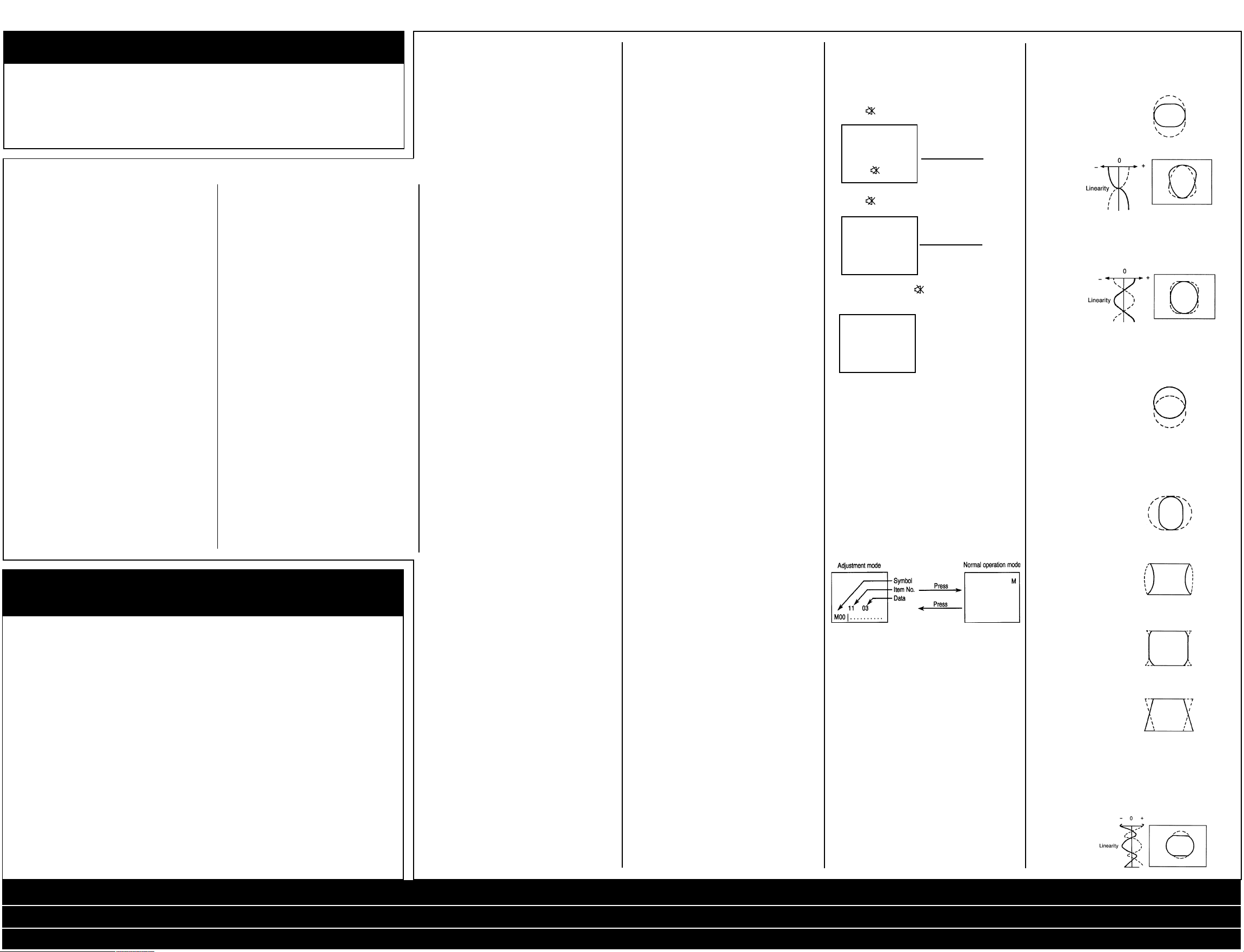
Service Mode General
Instructions
1. ENTERING TO SERVICE MODE
1) Press button once on Remote Control.
➤
2) Press button again to keep pressing.
➤
3) Keep pressing the button, press MENU
button on TV set.
RCUT S
32H
(Service mode dIsplay)
2. SELECTING THE ADJUSTING ITEMS
Every pressing of CHANNEL ▲ button changes
the adjustment items in the following order.
(▼ button for reverse order.)
3. ADJUSTING THE DAT A
Pressing of VOLUME ▲ or ▼ button will change
the value of data in the range from 00 to FF. The
variable range depends on the adjusting item.
4. NORMAL OPERATION ON THE SERVICE
MODE
Press MENU button on TV.
5. EXIT FROM SERVICE MODE
Press POWER button on the remote control to
turn off the TV once.
See next page for Adjustment Procedure and
Rom Data List.
SUB DATA ADDITIONAL DESCRIPTION
Symbol Description
HIT V amplitude adjustment.
LIN V linearity correction 1.
Linearity balance
between top and bottom
screen.
VSC V linearity correction 2.
Linearity balance
between top/bottom and
center.
VPC V picture position
adjustment
VCP Setting of amount of V
amplitude correction
against variation of
screen brightness.
WID H amplitude adjustment.
DPC H pin-cushion distortion
correction.
CNR H pin-cushion distortion
correction at four
corners.
KEY Pedestal distortion
correction.
HCP Setting of amount of H
amplitude correction
against variation of
screen brightness.
VMC V linearity correction.
Linearity balance at 1/4,
3/4 areas from top.
Service Mode / Safety Parts / Safety Instructions / Service Adjustments / Adjustment Procedure / Block Diagram
Signal Processing (2555 & 2855) ... Cont’d / Signal Processing (2552 & 2852) ... Cont’d
Power Audio Deflection (2555 & 2855) ... Cont’d / Power Audio Deflection (2552 & 2852) ... Cont’d
Page 2
TOSHIBA 2555 DB
Adjustment Procedure
Adjustment parts or Input point/ Adjustment signal Adjustment conditions and procedures
Bus control item Output point
Horizontal amplitude Visual check of picture WG Philips pattern 1. Conditions: After V. HEIGHT, VERT POSITION
adjustment (WID) (Bus control) and H. CENT have been adjusted, set
Pin distortion Do not use the Philips the controllers as follows:
compensation amount pattern of Contrast: MAX
adjustment (DPC) FRANCESECAM. Brightness: Center
Keystone distortion Color: Center
compensation amount 2. Adjustment procedure
adjustment (KEY) a. Adjust the horizontal amplitude by the sub
address WID. Adjust so that the left and right
white flags of Philips pattern disappear at the
very limits.
b. Make the left and right vertical bars straight
by the sub address DPC.
c. Compensate the key distortion by the sub
address KEY.
d. Again, adjust the sub address WID.
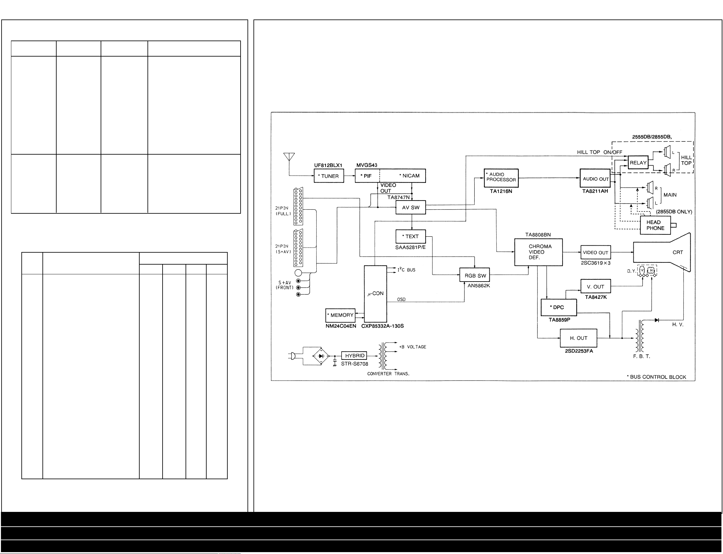
2
Block Diagram
HEIGHT (HIT) Visual check of picture Brightness: Center
VERT. POSITION (Bus control) Do not use the Philips Color: Center
ROM DATA LIST FOR IIC BUS CONTROL (Reference Value)
Symbol Comment Data
M00 MODE 0 51 51 51 51
M01 MODE 1 33 33 33 33
M01 MODE 1 USE ALPS TUNER 01 01 01 01
M02 MODE 2 03 03 02 02
M03 MODE 3 17 17 49 49
HIT HEIGHT *30 *30 *30 *30
LIN V. LINEARITY 32 32 32 32
VSC V. S-CORRECTION 32 32 32 32
VPS V. POSITION *07 *07 *07 *07
VCP V. COMPENSATION 30 30 30 30
WID H.WIDTH *22 *26 *22 *26
DPC DPC *26 *24 *26 *24
CNR DPC CORNER P44V32 32 P44V32 32
KEY KEYSTONE *09 *09 *09 *09
HCP H. COMPENSATION 10 10 10 10
VMC V. M-CORRECTION 52 41 52 41
SHI 16:9 SUB HEIGHT 00 00 00 00
SLI 16:9 SUB V. LINEARITY 32 32 32 32
SVS 16:9 SUB V.S-CORRECTION 17 17 17 17
SDP 16:9 SUB DPC P18V21 P17V21 P18V21 P17V21
SCN 16:9 SUB CORNER 30 30 30 30
WCT WOOFER FC SET 12 08 12 12
BAC BASS CENTER 40 34 50 50
TRC TREBLE CENTER 48 52 44 44
BAX BASS MAX 79 79 79 79
WON BAZOOKA AUTO 05 30 06 06
WOF BAZOOKA OFF 20 47 25 25
BAE BASS UP 01 03 01 01
TRE TREBLE UP 12 17 10 10
VOE VOL UP 02 02 00 00
WFL WOOFER LEVEL 100 100 100 100
EMX NICAM OFF LEVEL (PHIL) 252 252 252 252
EMN NICAM ON LEVEL (PHIL) 100 100 100 100
FMA FM INPUT ATT (PHIL) 00 00 00 00
STS STEREO SEPARATION — — — —
WG Philips pattern 1. Conditions:Contrast: Max
pattern of 2. Adjustment procedure
FRANCESECAM. a. By the bus address VPS, adjust V. position so
that the circle of Philips pattern comes to the
vertical center.
b. Adjust HIT so that the upper and lower flags of
Philips pattern disappear at the very limits.
2555DB 2855DB 2552DB 2852DB
* Mark items should be adjusted.
Service Mode / Safety Parts / Safety Instructions / Service Adjustments / Adjustment Procedure / Block Diagram
Signal Processing (2555 & 2855) ... Cont’d / Signal Processing (2552 & 2852) ... Cont’d
Power Audio Deflection (2555 & 2855) ... Cont’d / Power Audio Deflection (2552 & 2852) ... Cont’d
Page 3
TOSHIBA 2555 DB
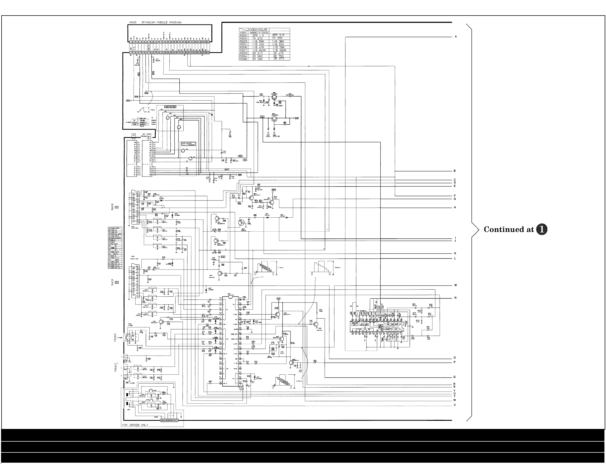
Signal Processing
(2555 & 2855)
Diagram
3
Service Mode / Safety Parts / Safety Instructions / Service Adjustments / Adjustment Procedure / Block Diagram
Signal Processing (2555 & 2855) ... Cont’d / Signal Processing (2552 & 2852) ... Cont’d
Power Audio Deflection (2555 & 2855) ... Cont’d / Power Audio Deflection (2552 & 2852) ... Cont’d
Page 4

TOSHIBA 2555 DB
Signal Processing
(2555 & 2855)
Diagram Cont’d
4
Service Mode / Safety Parts / Safety Instructions / Service Adjustments / Adjustment Procedure / Block Diagram
Signal Processing (2555 & 2855) ... Cont’d / Signal Processing (2552 & 2852) ... Cont’d
Power Audio Deflection (2555 & 2855) ... Cont’d / Power Audio Deflection (2552 & 2852) ... Cont’d
Page 5

TOSHIBA 2555 DB
Signal Processing
(2552 & 2852)
Diagram
5
Service Mode / Safety Parts / Safety Instructions / Service Adjustments / Adjustment Procedure / Block Diagram
Signal Processing (2555 & 2855) ... Cont’d / Signal Processing (2552 & 2852) ... Cont’d
Power Audio Deflection (2555 & 2855) ... Cont’d / Power Audio Deflection (2552 & 2852) ... Cont’d
Page 6

TOSHIBA 2555 DB
Signal Processing
(2552 & 2852)
Diagram Cont’d
6
Service Mode / Safety Parts / Safety Instructions / Service Adjustments / Adjustment Procedure / Block Diagram
Signal Processing (2555 & 2855) ... Cont’d / Signal Processing (2552 & 2852) ... Cont’d
Power Audio Deflection (2555 & 2855) ... Cont’d / Power Audio Deflection (2552 & 2852) ... Cont’d
Page 7

TOSHIBA 2555 DB
Power, Audio &
Deflection
Diagram
(2555 & 2855)
7
Service Mode / Safety Parts / Safety Instructions / Service Adjustments / Adjustment Procedure / Block Diagram
Signal Processing (2555 & 2855) ... Cont’d / Signal Processing (2552 & 2852) ... Cont’d
Power Audio Deflection (2555 & 2855) ... Cont’d / Power Audio Deflection (2552 & 2852) ... Cont’d
Page 8

TOSHIBA 2555 DB
Power, Audio &
Deflection Diagram
(2555 & 2855) Cont’d
8
Service Mode / Safety Parts / Safety Instructions / Service Adjustments / Adjustment Procedure / Block Diagram
Signal Processing (2555 & 2855) ... Cont’d / Signal Processing (2552 & 2852) ... Cont’d
Power Audio Deflection (2555 & 2855) ... Cont’d / Power Audio Deflection (2552 & 2852) ... Cont’d
Page 9

TOSHIBA 2555 DB
Power, Audio &
Deflection
Diagram
(2552 & 2852)
9
Service Mode / Safety Parts / Safety Instructions / Service Adjustments / Adjustment Procedure / Block Diagram
Signal Processing (2555 & 2855) ... Cont’d / Signal Processing (2552 & 2852) ... Cont’d
Power Audio Deflection (2555 & 2855) ... Cont’d / Power Audio Deflection (2552 & 2852) ... Cont’d
Page 10

TOSHIBA 2555 DB
Power, Audio &
Deflection Diagram
(2552 & 2852) Cont’d
10
Service Mode / Safety Parts / Safety Instructions / Service Adjustments / Adjustment Procedure / Block Diagram
Signal Processing (2555 & 2855) ... Cont’d / Signal Processing (2552 & 2852) ... Cont’d
Power Audio Deflection (2555 & 2855) ... Cont’d / Power Audio Deflection (2552 & 2852) ... Cont’d
 Loading...