

Page 1
MULTIFUNCTIONAL DIGITAL COLOR SYSTEMS
Quick Start Guide
Page 2
Lineup of Our Manuals
Some of these manuals are printouts and others are PDF les recorded in the Client Utilities/User Documentation DVD.
In the printouts, precautions and basic operations are described. Be sure to read “Safety Information” before using the
equipment. In the PDF les, detailed copying functions and other settings are described. Select and read those best suited to
your needs.
Printouts
Safety Information
This Safety Information describes the necessary precautions for use. For your added security, be
sure to read this booklet rst.
PDF les recorded in the "Client Utilities/User Documentation DVD".
Quick Start Guide (This manual)
This Quick Start Guide describes the preparations, basic and advanced usage, maintenance and
regular cleaning of the equipment.
PDF les recorded in the "Client Utilities/User Documentation DVD".
How to use the Client Utilities/User Documentation DVD
Windows:
1. Set the Client Utilities/User Documentation DVD in the DVD-ROM drive on your computer.
Software Installer starts automatically.
If Software Installer does not launch, use the explorer to open the [e-STUDIO] folder in the Client Utilities/User Documentation DVD
and double-click “Setup.exe”.
2. Select [I agree to the terms of the License Agreement.] and click [Next].
3. Click the Open User’s Manual link in Software Installer.
The browser starts automatically and the menu for choosing a language is displayed.
If the menu is not displayed, use the explorer to open the [Manuals] folder in the Client Utilities/User Documentation DVD and
double-click “index.html”.
4. Click the desired language button. The menu for choosing the equipment is displayed.
5. Click the desired equipment button to display the menu for choosing an operator's manual.
6. Click the title of the operator’s manual to be viewed from the menu. Its PDF le is displayed.
Macintosh:
1. Set the Client Utilities/User Documentation DVD in the DVD-ROM drive on your computer.
2. Open the [Manuals] folder in the Client Utilities/User Documentation DVD and open the desired language folder.
3. Double-click the le of the operator
’s manual to be viewed. Its PDF le is displayed.
Page 3

PDF les
Copying Guide
This Copying Guide describes the operations and settings
enabled with the [COPY] button on the control panel.
Scanning Guide
This Scanning Guide describes the operations and settings
enabled with the [SCAN] button on the control panel and
those of Internet Fax.
e-Filing Guide
This e-Filing Guide describes the operations and settings
enabled with the [e-FILING] button on the control panel
and the e-Filing web utility.
This e-Filing web utility enables you to operate e-Filing
using the browser on your computer.
MFP Management Guide
This MFP Management Guide describes the operations and
settings enabled with the [USER FUNCTIONS] button and
the [COUNTER] button on the control panel.
Software Installation Guide
This Software Installation Guide describes the installation
procedures for printer drivers and utilities.
Printing Guide
This Printing Guide describes the settings of printer drivers
required for printing and the various procedures.
TopAccess Guide
This TopAccess Guide describes procedures for remote
setup and management from a web-based utility,
“TopAccess”.
This “TopAccess” web utility enables you to manage the
equipment using the browser on your computer.
Troubleshooting Guide
This Troubleshooting Guide describes how to deal with
problems, such as paper misfeeds, as well as how to react
to messages displayed on the touch panel.
Network Fax Guide
This Network Fax Guide describes the operations of the
N/W-Fax Driver.
The N/W-Fax driver enables you to send electronic
documents as faxes or Internet faxes from your computer.
High Security Mode Management Guide
This High Security Mode Management Guide describes the
conditions and settings to use the equipment in the high
security mode.
Help menu for client software
To run the following client software, refer to the Help menu
of each:
AddressBook Viewer
•
e-Filing Backup/Restore Utility
•
TWAIN Driver / File Downloader
•
Operator’s manuals of options
In the following options sold separately, the corresponding
operator’s manuals are co-packed.
GD-1320/GD-1260 Operator’s Manual for FAX Unit
•
GN-1060 Operator’s Manual for Wireless LAN Module
•
GP-1070 Operator’s Manual for Data Overwrite Enabler
•
KP-2004 Operator’s Manual for e-BRIDGE ID Gate
•
KP-2005 Operator’s Manual for e-BRIDGE ID Gate
•
To read manuals in PDF (Portable Document Format) les
Viewing and printing manuals in PDF les require that you install Adobe Reader or Adobe Acrobat Reader on your PC. If
Adobe Reader or Adobe Acrobat Reader is not installed on your PC, download and install it from the website of Adobe
Systems Incorporated.
Page 4
How to Read This Manual
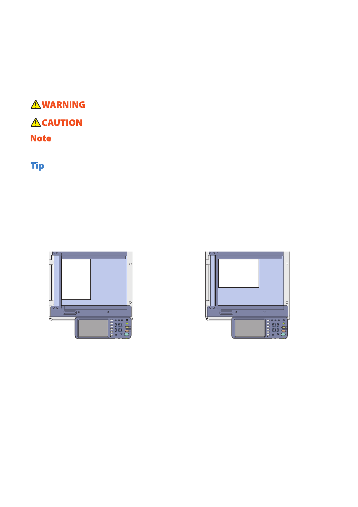
Symbols in this manual
In this manual, some important items are described with the symbols shown below. Be sure to read these items before
using this equipment.
Indicates a potentially hazardous situation which, if not avoided, could result in death, serious injury, or
serious damage, or re in the equipment or surrounding objects.
Indicates a potentially hazardous situation which, if not avoided, may result in minor or moderate injury,
partial damage to the equipment or surrounding objects, or loss of data.
Indicates information to which you should pay attention when operating the equipment.
Read the following description as required.
Describes handy information that is useful to know when operating the equipment.
&
Indicates the pages describing items related to what you are currently doing.
Description of original/paper direction
Paper or originals of A4 or B5 / LT size can be placed either in a portrait direction or in a landscape direction. In this
manual, “-R” is added to this paper size when this size of paper or original is placed in a landscape direction.
Example: A4 / LT size original on the original glass
Placed in a portrait direction: A4 / LT
Placed in a landscape direction: A4-R / LT-R
2
Paper or originals of A3 or B4 / LD or LG size can only be placed in a landscape direction, therefore “-R” is not added to
these sizes.
Screens and Operation Procedures
In this manual, the screens and the operation procedures in Windows are described for Windows 7.
•
The details on the screens may dier depending on how the equipment is used, such as the status of the installed
options, the OS version and the applications.
The illustration screens used in this manual are for paper in the A/B format. If you use paper in the LT format, the display
•
or the order of buttons in the illustrations may dier from that of your equipment.
Page 5

CONTENTS
How to Read This Manual . . . . . . . . . . . . . . . . . . . . . . . . . . . . . . . . . . . . . . . . . . . . . . . . . . . . . . . . . . . . . . . . . . . . . . . . . . . . . . . . . . . . . . . . . . 2
Recommended toner cartridges . . . . . . . . . . . . . . . . . . . . . . . . . . . . . . . . . . . . . . . . . . . . . . . . . . . . . . . . . . . . . . . . . . . . . . . . . . . . . . . . . . . .4
Chapter 1 PREPARATIONS
Description of Each Component . . . . . . . . . . . . . . . . . . . . . . . . . . . . . . . . . . . . . . . . . . . . . . . . . . . . . . . . . . . . . . . . . . 6
Turning Power ON/OFF . . . . . . . . . . . . . . . . . . . . . . . . . . . . . . . . . . . . . . . . . . . . . . . . . . . . . . . . . . . . . . . . . . . . . . . . .12
Placing Paper and Originals . . . . . . . . . . . . . . . . . . . . . . . . . . . . . . . . . . . . . . . . . . . . . . . . . . . . . . . . . . . . . . . . . . . . .15
Installing Client Software . . . . . . . . . . . . . . . . . . . . . . . . . . . . . . . . . . . . . . . . . . . . . . . . . . . . . . . . . . . . . . . . . . . . . . .17
Chapter 2 BASIC OPERATION
Basic Copying Operation . . . . . . . . . . . . . . . . . . . . . . . . . . . . . . . . . . . . . . . . . . . . . . . . . . . . . . . . . . . . . . . . . . . . . . . .20
Basic Fax Operation . . . . . . . . . . . . . . . . . . . . . . . . . . . . . . . . . . . . . . . . . . . . . . . . . . . . . . . . . . . . . . . . . . . . . . . . . . . . .24
Basic Scanning Operation . . . . . . . . . . . . . . . . . . . . . . . . . . . . . . . . . . . . . . . . . . . . . . . . . . . . . . . . . . . . . . . . . . . . . . .28
Basic e-Filing Operation . . . . . . . . . . . . . . . . . . . . . . . . . . . . . . . . . . . . . . . . . . . . . . . . . . . . . . . . . . . . . . . . . . . . . . . . .30
Basic Printing Operation . . . . . . . . . . . . . . . . . . . . . . . . . . . . . . . . . . . . . . . . . . . . . . . . . . . . . . . . . . . . . . . . . . . . . . . .32
Basic Menu Operation . . . . . . . . . . . . . . . . . . . . . . . . . . . . . . . . . . . . . . . . . . . . . . . . . . . . . . . . . . . . . . . . . . . . . . . . . .34
Chapter 3 MAINTENANCE
Replacing Toner Cartridge . . . . . . . . . . . . . . . . . . . . . . . . . . . . . . . . . . . . . . . . . . . . . . . . . . . . . . . . . . . . . . . . . . . . . .36
Replacing Waste Toner Box . . . . . . . . . . . . . . . . . . . . . . . . . . . . . . . . . . . . . . . . . . . . . . . . . . . . . . . . . . . . . . . . . . . . . .37
Replacing Staple Cartridge . . . . . . . . . . . . . . . . . . . . . . . . . . . . . . . . . . . . . . . . . . . . . . . . . . . . . . . . . . . . . . . . . . . . . .38
Regular Cleaning . . . . . . . . . . . . . . . . . . . . . . . . . . . . . . . . . . . . . . . . . . . . . . . . . . . . . . . . . . . . . . . . . . . . . . . . . . . . . . .42
Chapter 4 TROUBLESHOOTING
Troubleshooting . . . . . . . . . . . . . . . . . . . . . . . . . . . . . . . . . . . . . . . . . . . . . . . . . . . . . . . . . . . . . . . . . . . . . . . . . . . . . . . .46
Chapter 5 ADVANCED FUNCTIONS
Advanced Functions . . . . . . . . . . . . . . . . . . . . . . . . . . . . . . . . . . . . . . . . . . . . . . . . . . . . . . . . . . . . . . . . . . . . . . . . . . . .50
Chapter 6 INFORMATION ABOUT EQUIPMENT
Items Included in This Product . . . . . . . . . . . . . . . . . . . . . . . . . . . . . . . . . . . . . . . . . . . . . . . . . . . . . . . . . . . . . . . . . .60
Client Utilities/User Documentation DVD . . . . . . . . . . . . . . . . . . . . . . . . . . . . . . . . . . . . . . . . . . . . . . . . . . . . . . . .61
Client Software . . . . . . . . . . . . . . . . . . . . . . . . . . . . . . . . . . . . . . . . . . . . . . . . . . . . . . . . . . . . . . . . . . . . . . . . . . . . . . . . .62
Options . . . . . . . . . . . . . . . . . . . . . . . . . . . . . . . . . . . . . . . . . . . . . . . . . . . . . . . . . . . . . . . . . . . . . . . . . . . . . . . . . . . . . . . .64
Logging in . . . . . . . . . . . . . . . . . . . . . . . . . . . . . . . . . . . . . . . . . . . . . . . . . . . . . . . . . . . . . . . . . . . . . . . . . . . . . . . . . . . . . .67
Specications of Equipment . . . . . . . . . . . . . . . . . . . . . . . . . . . . . . . . . . . . . . . . . . . . . . . . . . . . . . . . . . . . . . . . . . . .70
Specications of Options . . . . . . . . . . . . . . . . . . . . . . . . . . . . . . . . . . . . . . . . . . . . . . . . . . . . . . . . . . . . . . . . . . . . . . . .73
INDEX . . . . . . . . . . . . . . . . . . . . . . . . . . . . . . . . . . . . . . . . . . . . . . . . . . . . . . . . . . . . . . . . . . . . . . . . . . . . . . . . . . . . . . . . . . . . . . . . . . . . . . . . . . . .79
3
Page 6

Recommended toner cartridges
To assure optimal printing performance, we recommend that you use only genuine TOSHIBA toner cartridges. If you use
a TOSHIBA-recommended toner cartridge, you can utilize the following three functions of this equipment:
Cartridge detecting function:
•
This function checks if the toner cartridge is correctly installed and noties you if it is not.
Toner remaining check function:
•
This function noties you when there is little toner remaining in the cartridge, as well as informing this to your
authorized service representative automatically by the remote service.
Image quality optimization function:
•
This function controls image quality according to the characteristics of the toner to be used and enables you to print
images of an optimal quality.
If you are using a toner cartridge other than the one we recommend, the equipment may not be able to detect whether
it is installed or not. Therefore, even if the toner cartridge is correctly installed, the error message “TONER NOT
RECOGNIZED” appears on the touch panel and printing may not be performed. You may also not be able to utilize the
image quality optimization function, the toner remaining check function and the remote service function notifying your
authorized service representative automatically.
If you are using a toner cartridge other than the one we recommend, the toner will not be recognized. If this is a problem
for you, please contact your service representative. Remember you will not be able to utilize the toner remaining check
function and Image quality optimization function as we mentioned.
4
Trademarks
The ocial name of Windows XP is Microsoft Windows XP Operating System.
•
The ocial name of Windows Vista is Microsoft Windows Vista Operating System.
•
The ocial name of Windows 7 is Microsoft Windows 7 Operating System.
•
The ocial name of Windows Server 2003 is Microsoft Windows Server 2003 Operating System.
•
The ocial name of Windows Server 2008 is Microsoft Windows Server 2008 Operating System.
•
Microsoft, Windows, Windows NT, and the brand names and product names of other Microsoft products are
•
trademarks of Microsoft Corporation in the US and other countries.
Apple, AppleTalk, Macintosh, Mac, Mac OS, Safari, and TrueType are trademarks of Apple Inc. in the US and other
•
countries.
Adobe, Acrobat, Reader, and PostScript are either registered trademarks or trademarks of Adobe Systems
•
Incorporated in the United States and/or other countries.
Mozilla, Firefox and the Firefox logo are trademarks or registered trademarks of Mozilla Foundation in the U.S. and
•
other countries.
IBM, AT and AIX are trademarks of International Business Machines Corporation.
•
NOVELL, NetWare and NDS are trademarks of Novell, Inc. in the US.
•
TopAccess is a trademark of Toshiba Tec Corporation.
•
Other company and product names given in this manual or displayed in this software may be the trademarks of
•
their respective companies.
Page 7

Chapter 1
PREPARATIONS
Description of Each Component . . . . . . . . . . . . . . . . . . . . . . . . . . 6
Turning Power ON/OFF . . . . . . . . . . . . . . . . . . . . . . . . . . . . . . . . . .12
Placing Paper and Originals . . . . . . . . . . . . . . . . . . . . . . . . . . . . .15
Installing Client Software . . . . . . . . . . . . . . . . . . . . . . . . . . . . . . . . 17
Page 8
Chapter 1 PREPARATIONS
15
16
13
14
12
11
1
6
5
7
8
9
10
3
4
Back side
2
18 17
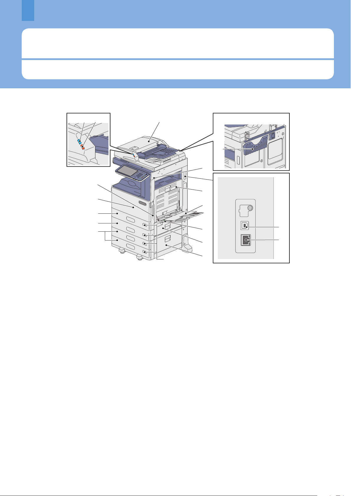
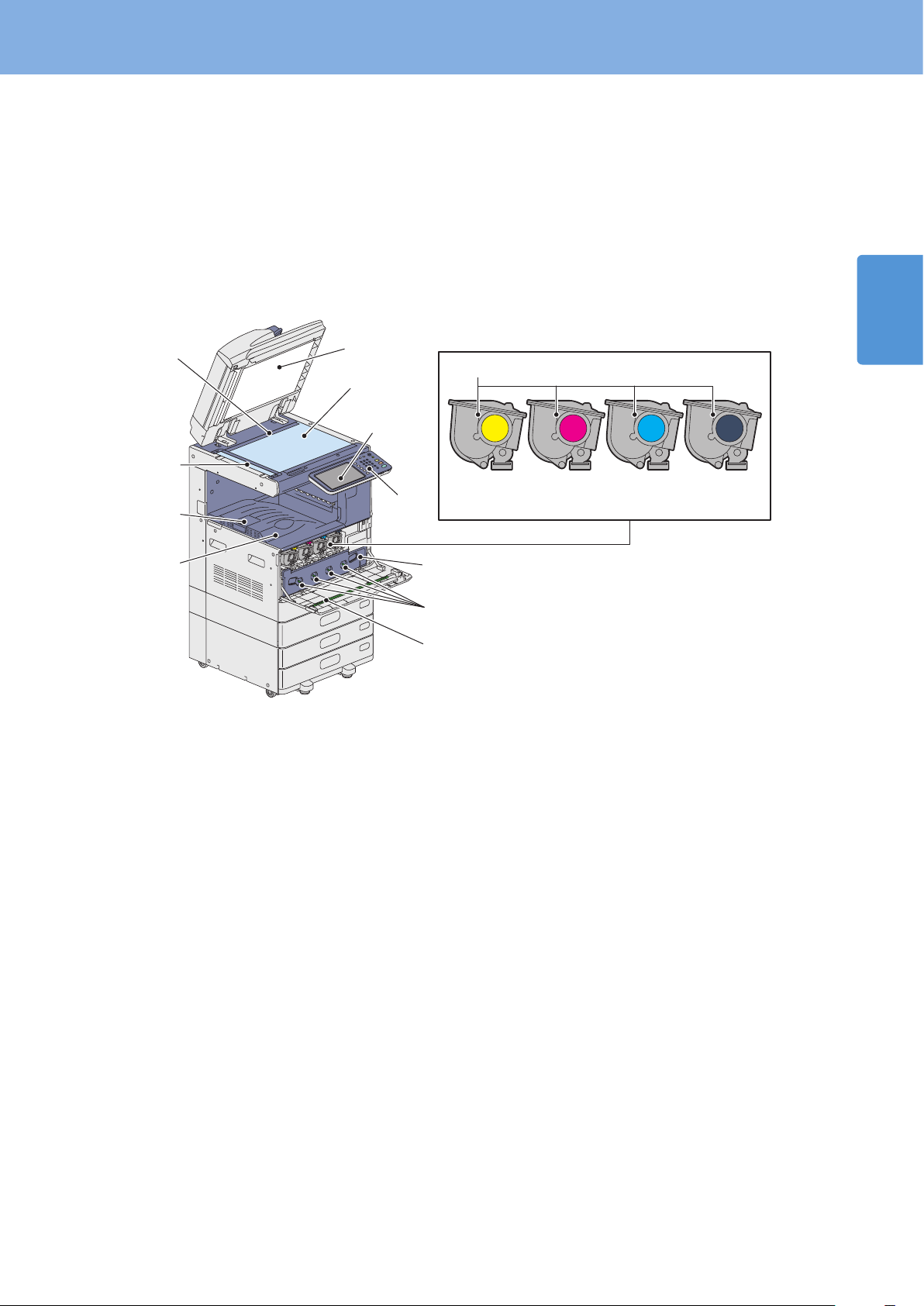
Description of Each Component
This section describes the names and operations of the equipment, control panel and touch panel.
Front / Right side
6
1.
Reversing Automatic Document Feeder
The stack of originals is scanned one sheet at a time. Both
sides of the originals can be scanned. A maximum of 100
sheets (80 g/m2 or 20 lb. Bond) can be placed in one go.
(The maximum number of sheets that can be set may vary
depending on the media type of the originals.)
2. Operator’s Manual Pocket (back side)
Keep the manual in this pocket.
3. USB terminal (4-pin)
Use this terminal when connecting this equipment to a PC
with a commercially available USB cable.
4. Network interface connector
Use this connector when connecting this equipment to a
network.
5. USB port
Use this connector when printing les stored in a USB
device or storing scanned data into the USB device.
The Front USB Cable is required for using the USB port.
6. Automatic duplexing unit
This unit makes copies on both sides of the paper. Open it
when paper misfeeds occur.
7. Bypass tray
Use this to perform printing on special media types such
as OHP lm, etc.
& P.23 “Bypass copying” in this manual
8. Paper holding lever
Use this to place paper on the bypass tray.
9. Paper feed cover (of the equipment)
Open this cover when releasing paper misfed in the
drawer feeding area.
10. Paper feed cover
Open this cover when releasing paper misfed in the Paper
Feed Pedestal or Large Capacity Feeder.
11. Paper size indicator
The size of the paper set in the drawer can be checked.
12. Paper Feed Pedestal and Additional Drawer
Module or Large Capacity Feeder
Use the Paper Feed Pedestal to add one drawer. The
Additional Drawer Module can be installed in this device.
A maximum of 550 sheets (80 g/m2 or 20 lb. Bond) of plain
paper can be placed in one go.
A maximum of 2000 sheets (80 g/m2 or 20 lb. Bond) of
plain paper can be placed in the Large Capacity Feeder.
13. Paper Feed Unit
Use the Paper Feed Unit to add the second drawer. A
maximum of 550 sheets (80 g/m2 or 20 lb. Bond) of plain
paper can be placed in one go.
14. Drawer
A maximum of 250 sheets of plain paper can be placed in
one go.
& P.15 “Placing paper” in this manual
Page 9
Description of Each Component
Yellow Magenta Cyan Black
10
12
11
9
5
3
4
6
8
7
2
1
15. Front cover
Open this cover when you replace the toner cartridge and
clean the charger.
16. Main power switch
Use this switch to turn the power of the equipment ON or
OFF.
& P.12 “Turning Power ON/OFF” in this manual
Left / Inner side
17. Alarm lamp
This orange lamp lights when a paper misfeed has
occurred in the Reversing Automatic Document Feeder.
18. Document lamp
This blue lamp lights when the originals are placed on the
original feeder tray. It also blinks while the originals are
being scanned.
1
1. Platen sheet
Use this to hold the original on the original glass to scan it.
& P.42 “Regular Cleaning” in this manual
2. Original glass
Use this to copy three-dimensional originals, book-type
originals and special paper such as OHP lm or tracing
paper, as well as plain paper.
3. Touch panel
Use this to set and operate various types of functions such
as copying, scanning and faxing. This also displays
messages, such as when paper runs out or paper misfeeds
occur.
& P.10 “Touch panel” in this manual
4. Control panel
Use this to set and operate various types of functions such
as copying and faxing.
& P.8 “Control panel” in this manual
5. Toner cartridge
When toner runs out, the message appears on the touch
panel. Replace the cartridge following the procedure
below.
& P.36 “Replacing Toner Cartridge” in this manual
6. Waste toner box
When “Dispose of used toner” appears on the touch panel,
replace the waste toner box according to the following
procedures.
& P.37 "Replacing Waste Toner Box" in this manual
7. Main charger cleaners
If unevenness occurs on the copied or printed paper, clean
the main chargers according to the following procedures.
& P.43 "Cleaning the main chargers and LED print heads"
in this manual
8. LED print head cleaner
If unevenness occurs on the copied or printed paper, clean
the LED print head according to the following procedures.
& P.43 "Cleaning the main chargers and LED print heads"
in this manual
9. Exit tray
Printed paper exits into this tray.
10. Paper exit stopper
Use this to prevent the exiting paper from falling. Open
this when you make many copies or prints on a larger size
of paper such as A3, B4, LD and LG.
11. Scanning area
The data of originals transported from the Reversing
Automatic Document Feeder are scanned here.
& P.42 “Regular Cleaning” in this manual
12. Original scale
Use this to check the size of an original placed on the
original glass.
7
Page 10
Chapter 1 PREPARATIONS
8
8
9
10
11
12
7654
3
21
21 20 19
22
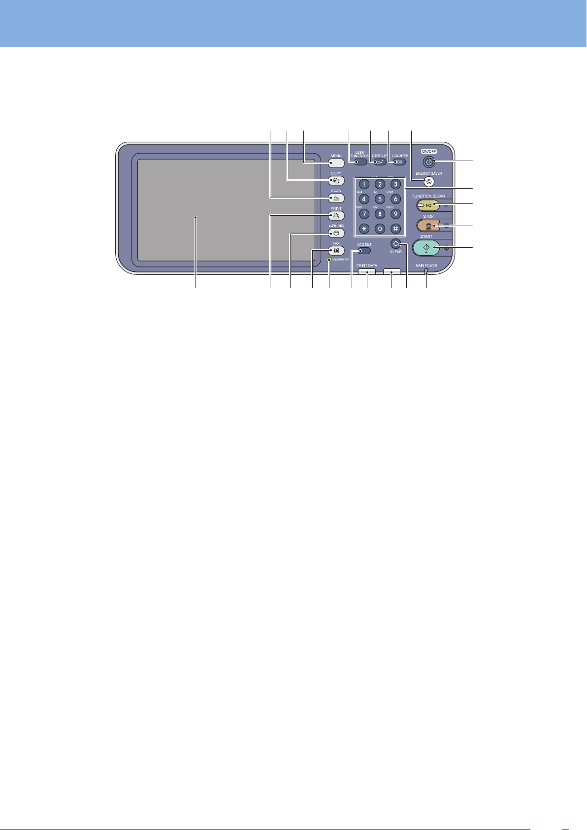
1415 131618 17
Control panel
Use the buttons on the control panel for various operations and settings in the equipment.
1. [SCAN] button
Use this button to access the scanning function.
2. [COPY] button
Use this button to access the copying function.
3. [MENU] button
Use this button to display frequently used templates.
4. [USER FUNCTIONS] button
Use this button for paper size or media type setting of
drawers, and registration of the copy, scan and fax settings
including a default setting change.
& MFP Management Guide (PDF): “Chapter 1: SETTING
ITEMS (USER)”
& MFP Management Guide (PDF): “Chapter 2: SETTING
ITEMS (ADMIN)”
5. [INTERRUPT] button
Use this button to interrupt print processing and perform
a copy job. The interrupted job is resumed through your
pressing this button again.
6. [COUNTER] button
Use this button to display the counter.
& MFP Management Guide (PDF): “Chapter 3: MANAGING
COUNTERS (COUNTER MENU)”
7. [ENERGY SAVER] button
Use this button for the equipment to enter the energy
saving mode.
8. [POWER] button
Use this button to turn the power of the equipment ON or
OFF (shutdown).
9. Digital keys
Use these keys to enter any numbers such as the number
of copies, telephone numbers or passwords.
10. [FUNCTION CLEAR] button
When this button is pressed, all selected functions are
cleared and returned to the default settings. If the default
setting is changed on the control panel, and then copying,
scanning, faxing or similar is performed, the lamp of this
button (orange) blinks.
11. [STOP] button
Use this button to stop any scanning and copying
operations in progress.
12. [START] button
Use this button to start copying, scanning and faxing
operations.
13. MAIN POWER lamp
This green lamp lights when the main power switch is ON.
14. [CLEAR] button
Use this button to correct the numbers keyed in, such as
the number of copy sets.
15. Alarm lamp
This orange lamp lights when an error occurs and some
action needs to be taken.
16. PRINT DATA lamp
This blue lamp lights during reception of data such as
print data.
17. [ACCESS] button
18. MEMORY RX / LINE lamp
Use this button when the department code or user
information has been set. If this button is pressed after
copying, etc., the next user needs to enter the department
code or user information.
& P.67 “Logging in” in this manual
This green lamp lights in the status of the fax data
reception and fax communication. The equipment can be
operated even while these lamps are lit.
Page 11
Description of Each Component
19. [FAX] button
Use this button to access the Fax / Internet Fax function.
20. [e-FILING] button
Use this button to access stored image data.
This button is not provided for the e-STUDIO2051C/
2551C.
21. [PRINT] button
Use this button to access the printing functions such as
private printing, in this equipment.
22. Touch panel
Use this panel for the various settings of the copying,
scanning and Fax functions. This also displays messages,
such as when paper runs out or paper misfeeds occur.
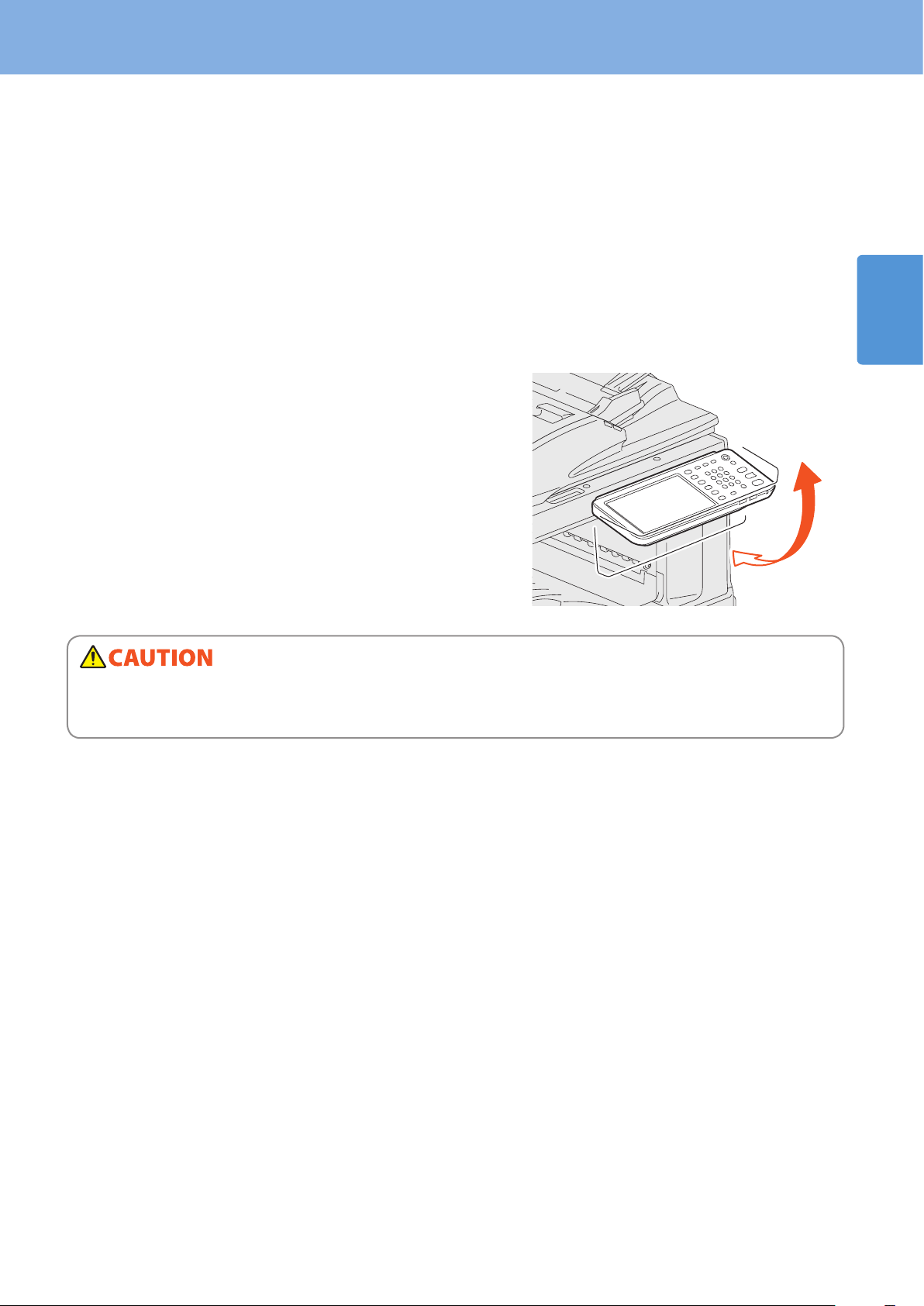
Adjusting the angle of the control panel
The angle of the control panel is adjustable at any angle between 7 and 90 degrees from the horizontal position.
1
When changing the angle of the control panel, be careful not to catch your hands in the gap between the equipment and
the control panel.
This could injure you.
9
Page 12
Chapter 1 PREPARATIONS
5
6
3
4
1
2
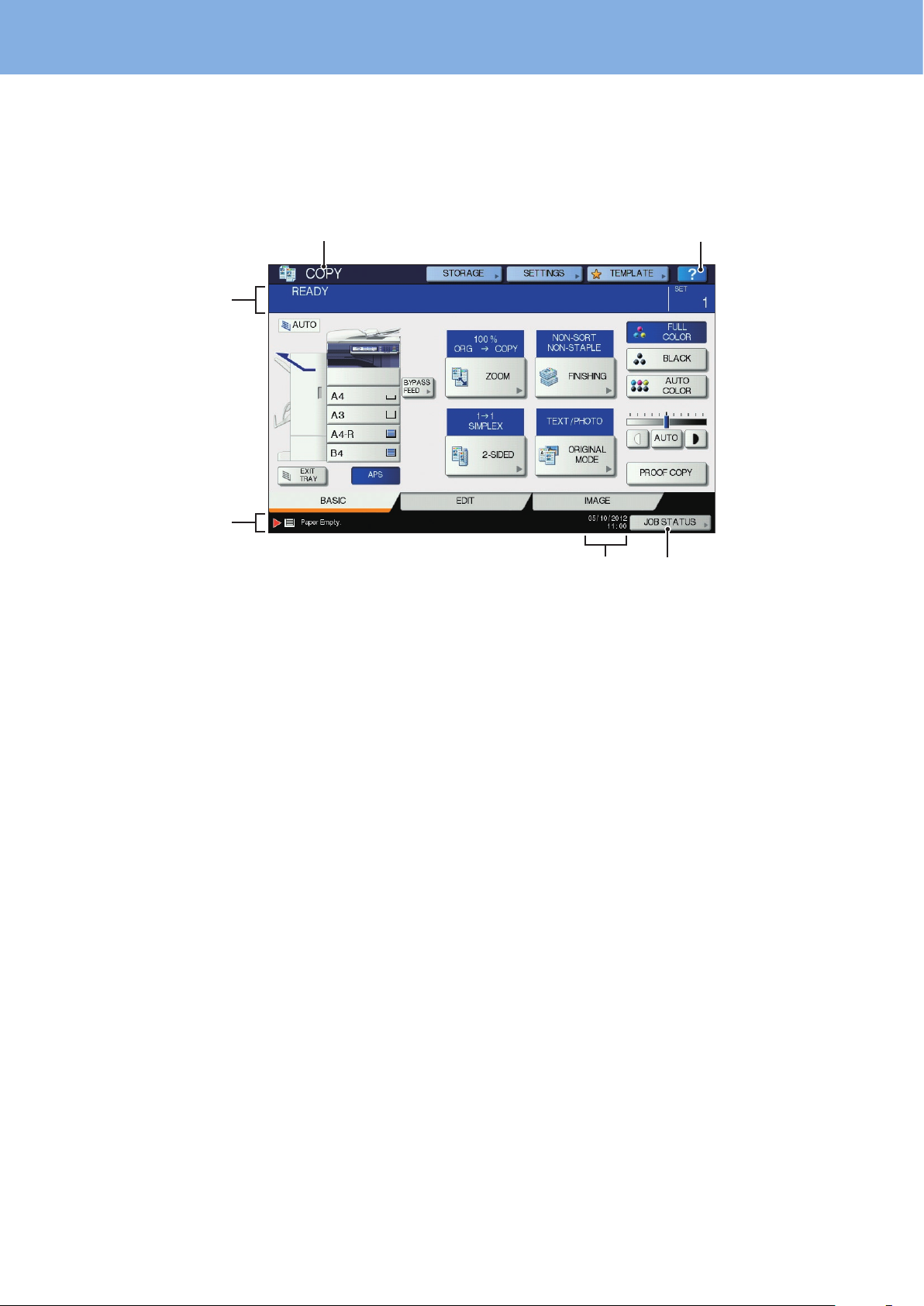
Touch panel
When the power is turned ON, the basic menu for copying functions is displayed on this touch panel. The status of the
equipment is also displayed on the touch panel with messages and illustrations.
The menu shown at the time of turning the power ON can be changed to one for functions other than copying, for
example, Fax function. Contact your service technician or representative for details.
1. Function display
The function being used, such as copying or faxing, is
displayed.
2. [?] (HELP) button
Use this button to view the explanation of each function
or the buttons on the touch panel.
& P.47 “Using the Help functions” in this manual
3. [JOB STATUS] button
This indicates the processing status of copy, fax, scan or
print jobs, and also allows you to view their performance
history.
Message displayed
The following information appears on the touch panel:
Equipment status
•
Operational instructions
•
Cautionary messages
•
Reproduction ratios
•
Number of copy sets
•
Paper size and amount of paper remaining in a selected drawer
•
Date and time
•
4. Date and time
The present date and time are displayed.
5. Alert message indication area
This shows alert messages such as when the toner
cartridges must be replaced.
6. Message indication area
The explanation of each operation or the current status is
displayed in message form.
10
Touch buttons
Press these buttons on the touch panel lightly to set various functions.
Adjusting the contrast of the touch panel
You can set the contrast of the touch panel in the USER FUNCTIONS menu entered by pressing the [USER FUNCTIONS]
button on the control panel.
& MFP Management Guide (PDF): “Chapter 1: SETTING ITEMS (USER)” - “Setting General Functions”
Page 13
Description of Each Component
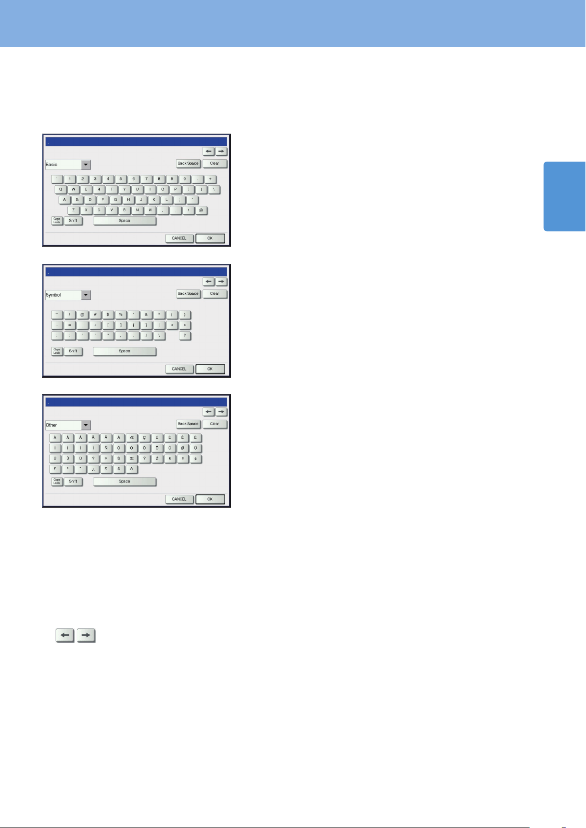
Setting letters
The following menu is displayed when the entry of any letter is required for scanning or e-Filing, etc.
Use the buttons on the touch panel for letter entry.
After entering the letters, press [OK]. The menu will be changed.
1
The following buttons are used for letter entry.
[Basic]: Press this to access the basic keys.
[Symbol]: Press this to access the symbol keys.
[Other]: Press this to access the special keys.
[Caps Lock]: Press this to switch capital letters and small letters.
[Shift]: Press this to enter capital letters.
[Space]: Press this to enter a space.
: Press these to move the cursor.
[Back Space]: Press this to delete the letter before the cursor.
[Clear]: Press this to delete all letters entered.
[CANCEL]: Press this to cancel the entry of letters.
[OK]: Press this to x all entered letters.
11
Page 14
Chapter 1 PREPARATIONS
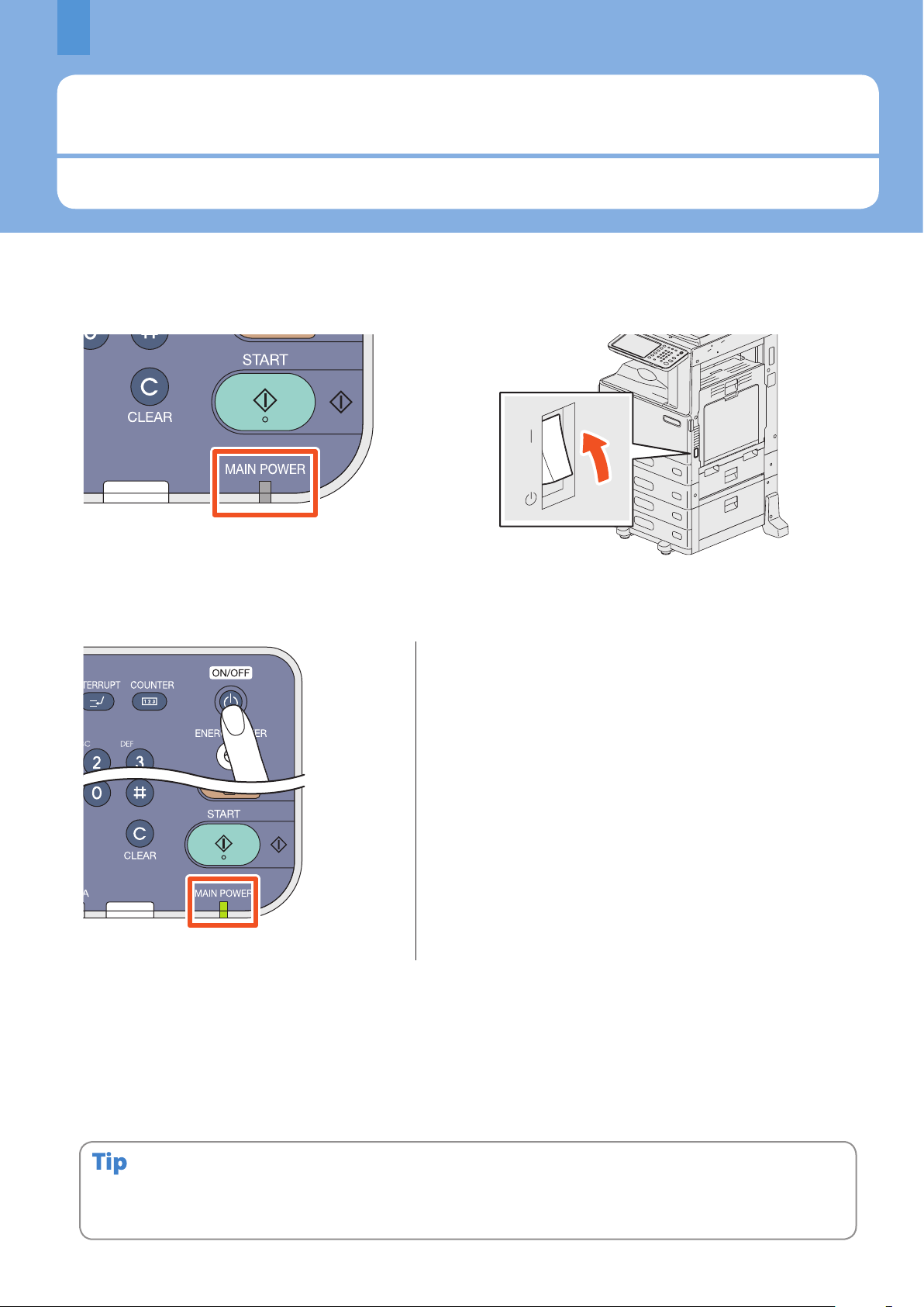
Turning Power ON/OFF
This section explains how to turn the power ON and OFF as well as the energy saving mode. How to turn the power ON diers
between when the MAIN POWER lamp (green) on the control panel is lit and when it is not.
Turning the power ON
When the MAIN POWER lamp (green) on the control panel does not light:
Turn the power ON there.
When the MAIN POWER lamp (green) on the control panel lights:
The equipment starts warming-up. “Wait Warming Up” appears
•
during warming-up.
While the equipment is warming up, you can use the auto job
•
start function. For details, refer to the following guide:
& Copying Guide (PDF): “Chapter 2: HOW TO MAKE COPIES” -
“Making Copies”
Press the [POWER] button.
When the equipment is ready for copying, “READY” will appear.
When you turn the power of the equipment OFF, be sure also to shut it down by pressing the [POWER] button on the
control panel. Do not simply turn the main power switch OFF. For details, see the following page:
& P.13 “Turning the power OFF (Shutdown)” in this manual
12
When “ERASING DATA” appears
This message appears when the Data Overwrite Enabler has been installed. It appears immediately after the power is
turned ON or after the equipment has been operated. You can operate the equipment even if it is displayed.
When the equipment is controlled under the department or user management function, enter the department code or user
information rst. For details, see the following page:
& P.67 “Logging in” in this manual
Page 15
Turning Power ON/OFF
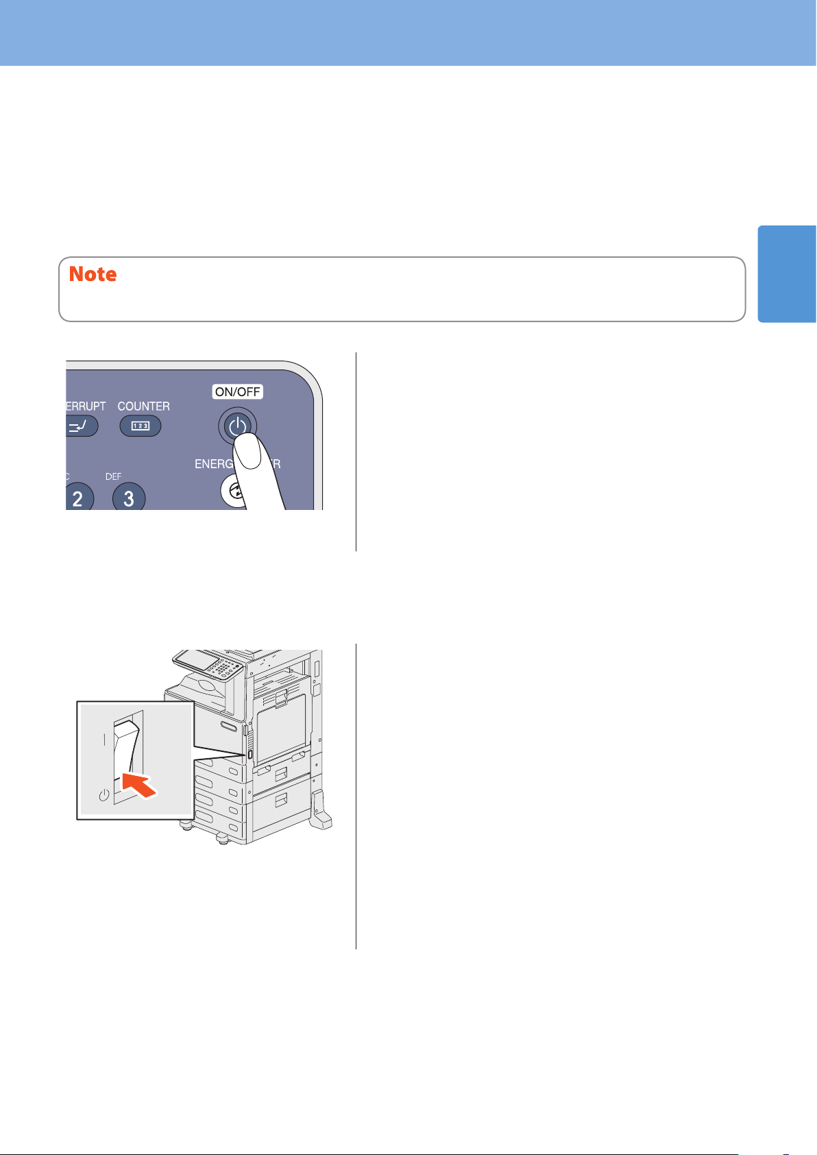
Turning the power OFF (Shutdown)
When turning the power of the equipment OFF, be sure to shut it down according to the procedure below. Check the
following three points before shutdown.
No jobs should be left in the print job list.
•
None of the PRINT DATA lamp (blue) or the MEMORY RX / LINE lamp (green) should be blinking.
•
(If the equipment is shut down while any of the above lamps is blinking, jobs in progress such as FAX reception will be
aborted.)
No computer should access the equipment via the network, such as TopAccess.
•
If a job in process exists when the [POWER] button of the control panel is pressed, “Processing job will be deleted. Are you sure you
want to shutdown?” appears.
“Shutdown is in progress.” appears for a while, and then the
power is turned OFF.
Press the [POWER] button until a “pip” sound is
heard.
When the equipment is not used for a long period of time:
When the power is turned OFF with the main power switch, the
MAIN POWER lamp (green) will go out.
1
Press the [POWER] button on the control panel to
shut down the equipment, check that the [ENERGY
SAVER] button (green) stops blinking and is
denitely not lit, and then turn the power OFF with
the main power switch.
13
Page 16
Chapter 1 PREPARATIONS
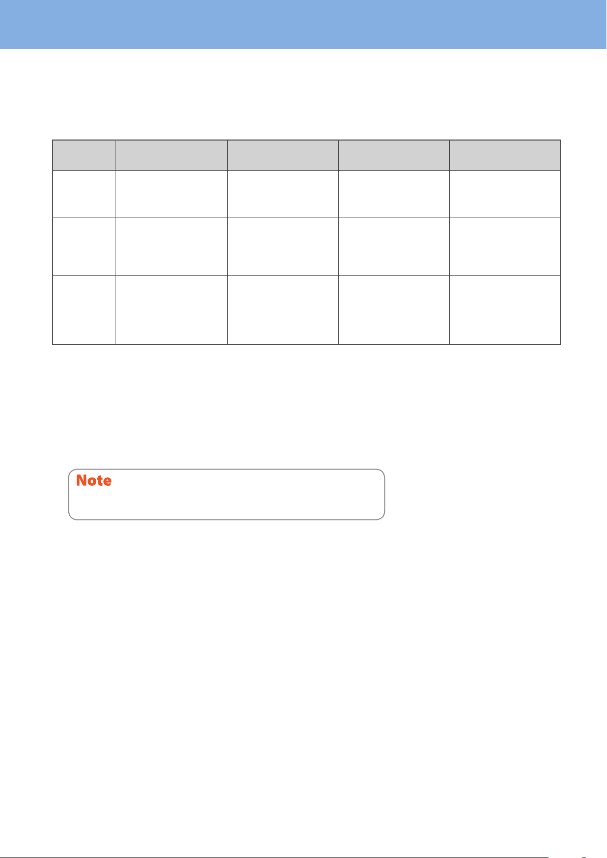
Saving energy when not in use – energy saving modes –
This equipment supports three energy saving modes; the Automatic Energy Save mode, Sleep mode and Super Sleep
mode. The table below shows the procedures to switch modes manually and the conditions under which the equipment
enters into or recovers from each mode.
Energy saving
modes
Automatic
Energy Save
mode
Sleep mode
Super Sleep
mode
*1 The default value set at the factory shipment is 1 minute.
*2 Any of the [START], [ENERGY SAVER], [COPY], [e-FILING], [SCAN], [PRINT ] and [FAX] buttons.
*3 [ENERGY SAVER] button on the control panel.
*4 The default value set at the factory shipment is 1 minute (The default value set at the factory shipment of the European version is 10 minutes).
*5 The Wireless LAN Module and/or e-BRIDGE ID Gate.
*6 Any of IPX, AppleTalk and other protocols. When the IPsec function is enabled or the Ethernet speed is set to [AUTO (-1000MB)] or [1000BASE FULL], the
equipment enters into the Sleep mode. For details, refer to the following guide:
& TopAccess Guide (PDF): “Chapter 8: [Administration] Tab Page” - “[Setup] Item list”
Procedure to switch
modes
When a specied period of
time *1 has passed since the
last use of the equipment.
When the [ENERGY SAVER]
button *3 is pressed or
when a specied period of
time *4 has passed since the
last use of the equipment.
When the [ENERGY SAVER]
button *3 is pressed or
when a specied period of
time *4 has passed since the
last use of the equipment.
Conditions to enter into
the mode
—
When a particular option *5
is installed or when a
particular protocol *6 is
enabled.
When a particular option *5
is not installed and also
when a particular protocol
*6
is disabled.
Status of equipment
“Saving energy - press
START button.” appears on
the touch panel.
The touch panel display
goes o and the [ENERGY
SAVER] button lights in
green.
Only the MAIN POWER
lamp (green) lights.
Conditions to recover
from the mode
When a button on the
control panel *2 is pressed
or when print data or fax
data are received.
Same as the Automatic
Energy Save mode.
When the [POWER] button
is pressed, when print or
fax data are received
through a wired LAN or
when the time set for
Scheduled Print has come.
For changing the set period of time for entering into each mode, refer to the following guide:
For the European version
Contact your service representative to change the default settings noted above.
& MFP Management Guide (PDF): “Chapter 2: SETTING ITEMS (ADMIN)” - “Setting General Functions”
When the set period of time for switching to the Automatic Energy Save mode is the same as that for the Sleep mode or
the Super Sleep mode, the equipment enters into the Sleep mode or the Super Sleep mode after the set period of time.
14
Page 17
Placing Paper and Originals
2
1
1
2
2
1
3
2
1
4
5
Placing Paper and Originals
This section explains how to set paper and originals. Incorrect setting causes image skews or paper misfeeds. Follow the
procedure below.
Placing paper
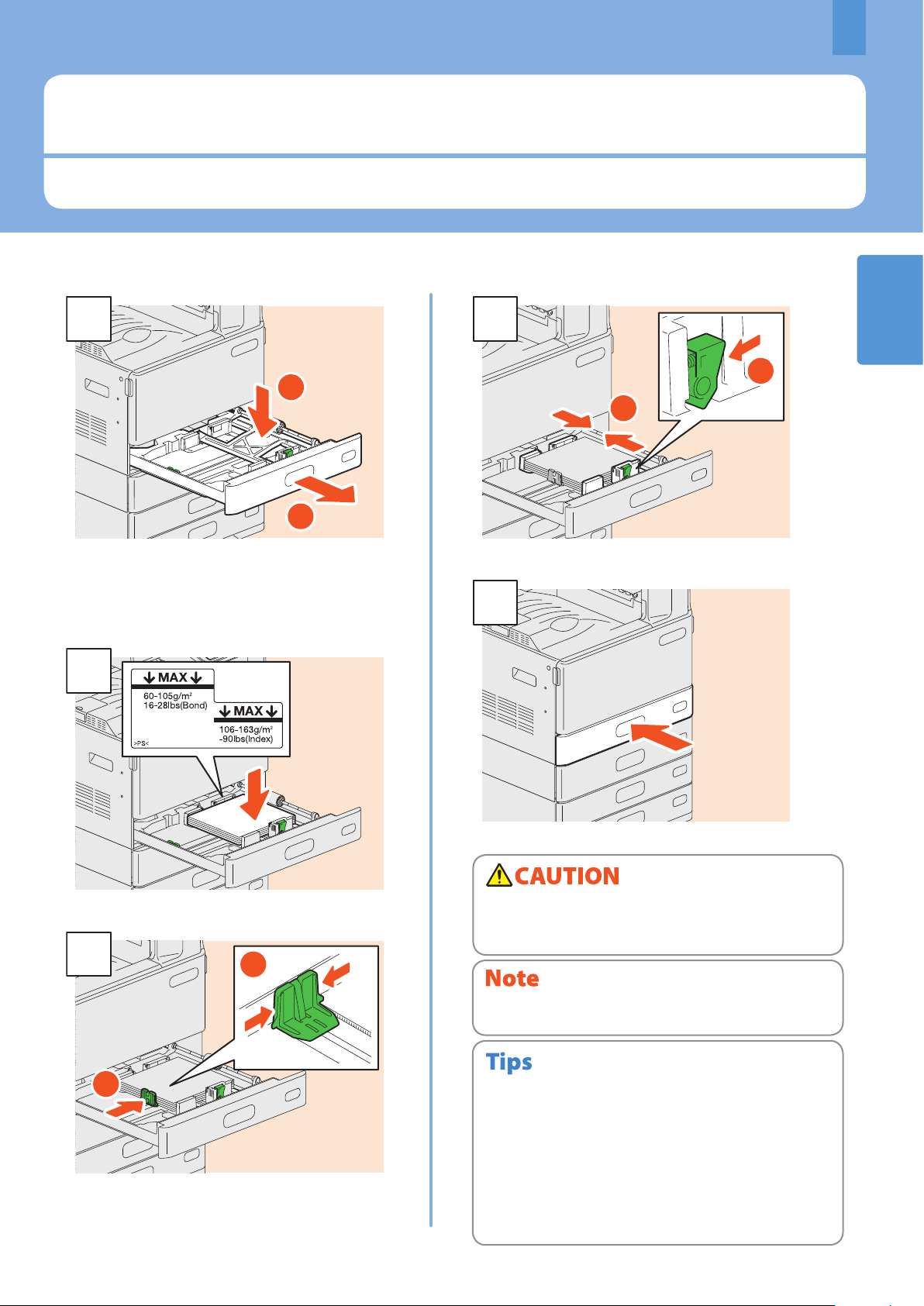
1
Pull out the drawer, and press down the paper
plate. When placing paper in the Paper Feed Unit,
Paper Feed Pedestal, or Additional Drawer
Module, pull out the drawer, and then proceed to
step 2.
Place paper face up.
Set the side guides so that they match the paper size.
Push in the drawer.
Be careful not to catch your ngers when pushing the
drawer back.
This could injure you.
Be sure that the height of the stacked paper does not exceed
the MAX line indicated on the side guides.
Set the end guide so that it matches the paper
size.
For paper available for the equipment, see the following
•
page:
& P.70 “Specications of Equipment” in this manual
Paper can be placed in the Paper Feed Unit, Paper Feed
•
Pedestal and Additional Drawer Module following the above
procedure. For placing paper in the Large Capacity Feeder,
refer to the following guide:
& Copying Guide (PDF): “Chapter 1: BEFORE USING
EQUIPMENT” - “Placing Paper”
15
Page 18
Chapter 1 PREPARATIONS
1
2
3
1
2
A4-R
(
LT-R
)B4(LD)
Placing originals
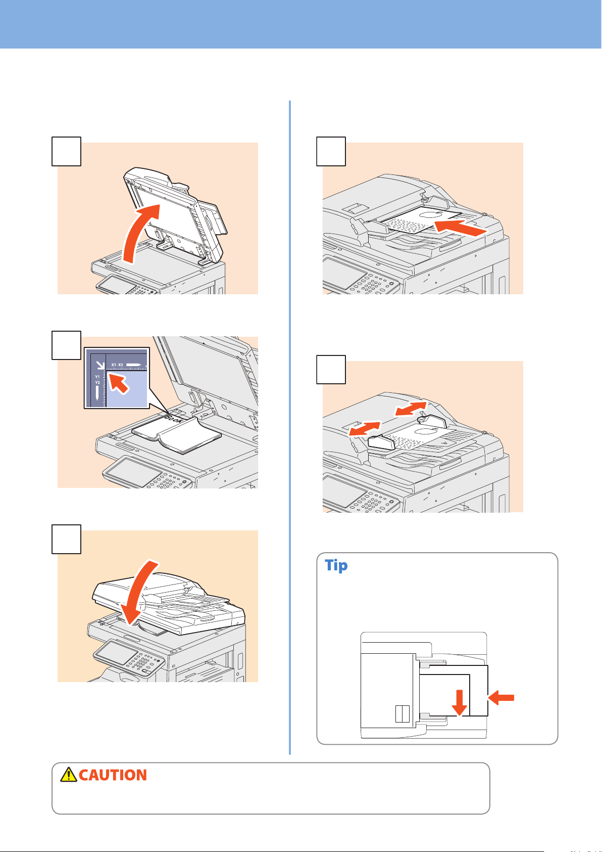
Original glass
Raise the Original Cover or the Reversing
Automatic Document Feeder.
Reversing Automatic Document
Feeder
Place the originals face up on the original feeder
tray. Be sure that the document lamp (blue) lights
up, which is provided on the Reversing Automatic
Document Feeder.
Place the original with its face down on the original
glass and align it against the left rear corner.
Align the side guides to the original length.
When placing mixed-size originals on the Reversing
Automatic Document Feeder, adjust its side guides to the
widest original, and then align the originals against the guide
on the front side.
Lower the Original Cover or the Reversing
Automatic Document Feeder carefully.
e-STUDIO2051C/2551C: Press [ZOOM] and set the
size of the original.
& Copying Guide (PDF): “Chapter 3: BASIC COPY
MODES” -“Enlargement and Reduction Copying”
Do not place any heavy objects (4 kg (9 lb.) or over) on the original glass and do not press on it with force.
Breaking the glass could injure you.
16
Page 19
Installing Client Software
11
22
33
44
55
2
66
2
1
Installing Client Software
How to install the client software such as the printer driver from the Client Utilities/User Documentation DVD co-packed with
the equipment is described as follows.
Recommended installation
The recommended client software such as the printer driver can be installed all in one go.
Turn the power ON and conrm that “READY” appears on the touch panel.
& P.12 “Turning Power ON/OFF” in this manual
Insert the Client Utilities/User Documentation DVD in the DVD-ROM drive of a Windows
computer.
To install the client software, log onto Windows with a user account which enables the installation such as
“Administrators”.
Select [I agree to the terms of the License Agreement.] and click [Next].
Click [Recommended].
Click [Install].
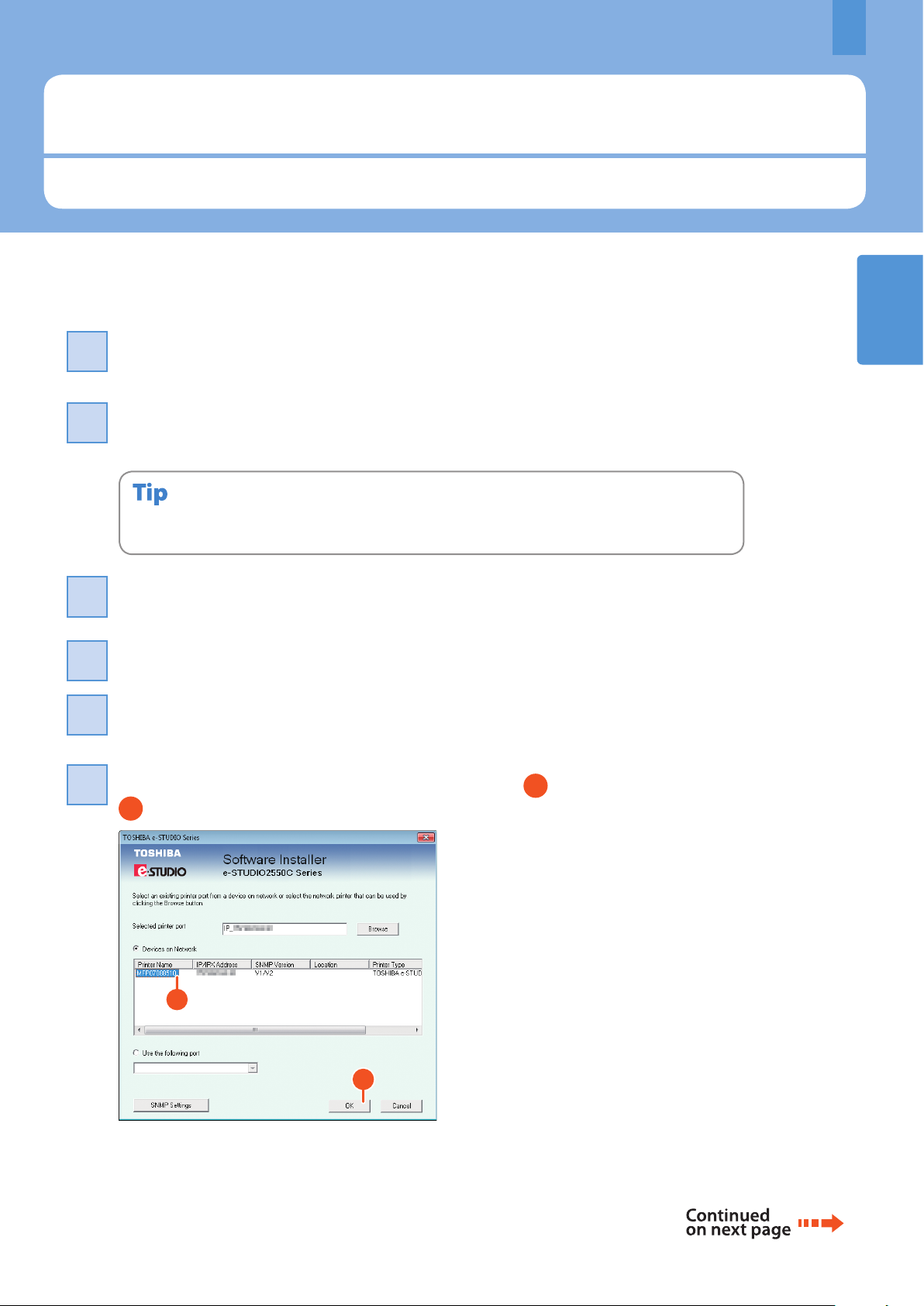
1
A list for the discovered printers is displayed. Then 1 select this equipment on the list and
click [OK].
17
Page 20
Chapter 1 PREPARATIONS
77
88
11
22
33
44
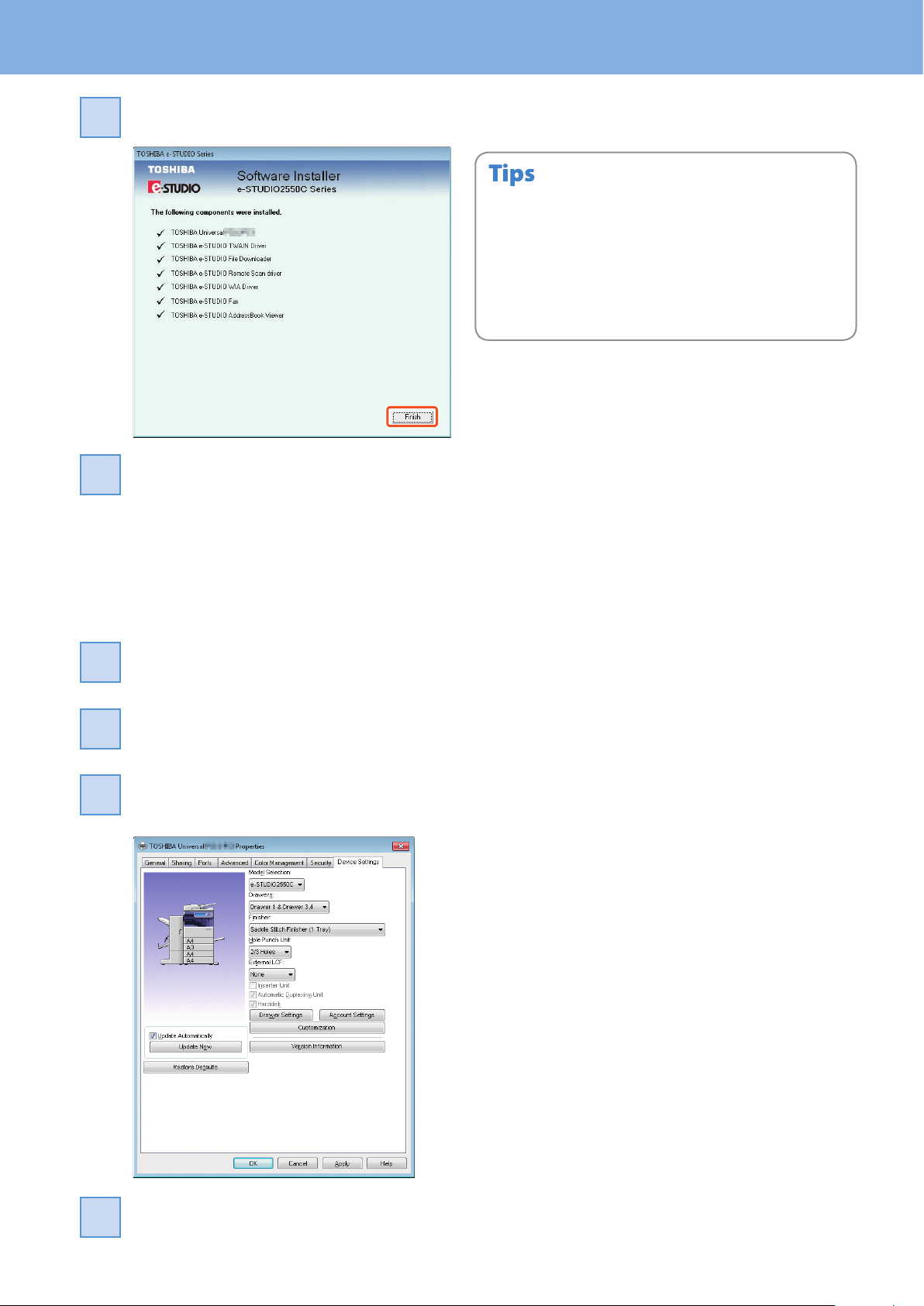
When the installation is completed, click [Finish].
Click [Exit] and then [Yes] to nish the installation.
For details of the Client Utilities/User Documentation DVD, see
•
the following page.
& P.61 “Client Utilities/User Documentation DVD“ in this
manual
For details of the recommended installation, refer to the
•
following guide.
& Software Installation Guide (PDF): “Chapter 2:
RECOMMENDED INSTALLATION”
Setting the printer driver
Before using the printer driver, you must congure the options installed in the equipment.
Select [Devices and Printers] in the [Start] menu.
Select TOSHIBA Universal Printer 2, right-click and then click [Printer Properties].
The conguration data of the options can be obtained automatically by opening the
[Device Settings] tab menu.
Click [OK]. The setting is completed.
18
Page 21

Chapter 2
BASIC OPERATION
Basic Copying Operation . . . . . . . . . . . . . . . . . . . . . . . . . . . . . . . .20
Basic Fax Operation . . . . . . . . . . . . . . . . . . . . . . . . . . . . . . . . . . . . .24
Basic Scanning Operation . . . . . . . . . . . . . . . . . . . . . . . . . . . . . . . 28
Basic e-Filing Operation . . . . . . . . . . . . . . . . . . . . . . . . . . . . . . . . .30
Basic Printing Operation . . . . . . . . . . . . . . . . . . . . . . . . . . . . . . . .32
Basic Menu Operation . . . . . . . . . . . . . . . . . . . . . . . . . . . . . . . . . . .34
Page 22
Chapter 2 BASIC OPERATION
11
22
44
33
2
1
Basic Copying Operation
The basic copying procedures, such as enlargement/reduction copying and duplex copying as well as bypass copying, are as
follows.
Making copies
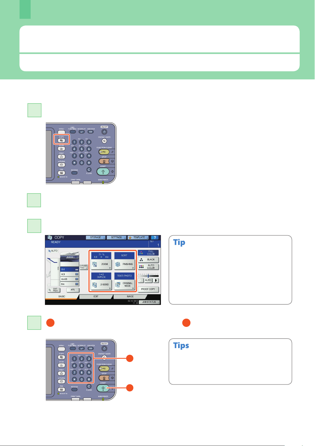
Press the [COPY] button on the control panel.
Place the original(s).
& P.16 “Placing originals” in this manual
Select the copy modes as required.
You can switch the color mode. There are 3 color modes as
shown below.
FULL COLOR: All originals are copied in full color. (Default)
BLACK: All originals are copied in black and white.
AUTO COLOR: The equipment automatically judges the
type of each color on originals. Colored
originals are copied in full color and blackand-white originals are copied in black and
white.
1 Key in the desired number of copies, and then 2 press the [START] button on the
control panel. Copying starts.
20
To stop copying, press the [STOP] button on the control
•
panel and then [MEMORY CLEAR] on the touch panel.
Printed paper exits to the exit tray of the equipment or the
•
Finisher. The tray to which the paper exits is indicated by
the arrow on the touch panel.
Page 23
Basic Copying Operation
11
1
2222
11
1
22
2
3
1
2
1
2
3
3
1
2
3
1
2
3
1
2
3
1
2
3
1
1
2
Sort
Group
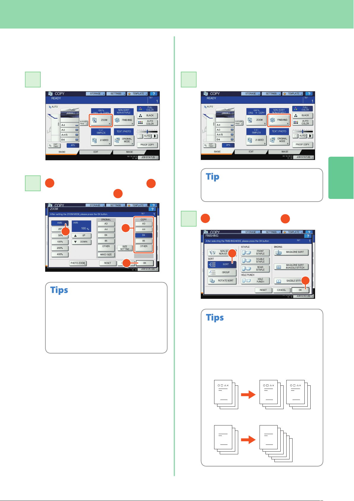
Enlargement and reduction
copying
Press [ZOOM].
Select the desired paper size, 2
press [AMS], and then 3 [OK].
Selecting nishing mode
(sorting)
Press [FINISHING].
2
When you use the Reversing Automatic Document
Feeder, the sorting mode is automatically set.
Align the originals according to the desired paper
•
size and direction. The size of the originals will be
automatically determined.
Automatic size detection for originals on the
•
original glass is available only for e-STUDIO
2050C/2550C.
When copying a set of originals whose sizes and
•
directions are dierent, press [MIXED SIZE].
Press [SORT] and then 2 [OK].
To set the staple and the hole punch mode, the
•
optional nishing devices are needed. For the
necessary options, see the following page.
& P.64 “Options” in this manual
For example, when “Original 1”, “Original 2” and
•
“Original 3” are copied in 2 sets, they can be made
as follows.
21
Page 24
Chapter 2 BASIC OPERATION
22
11
1
22
11
1
22
1
2
1
2
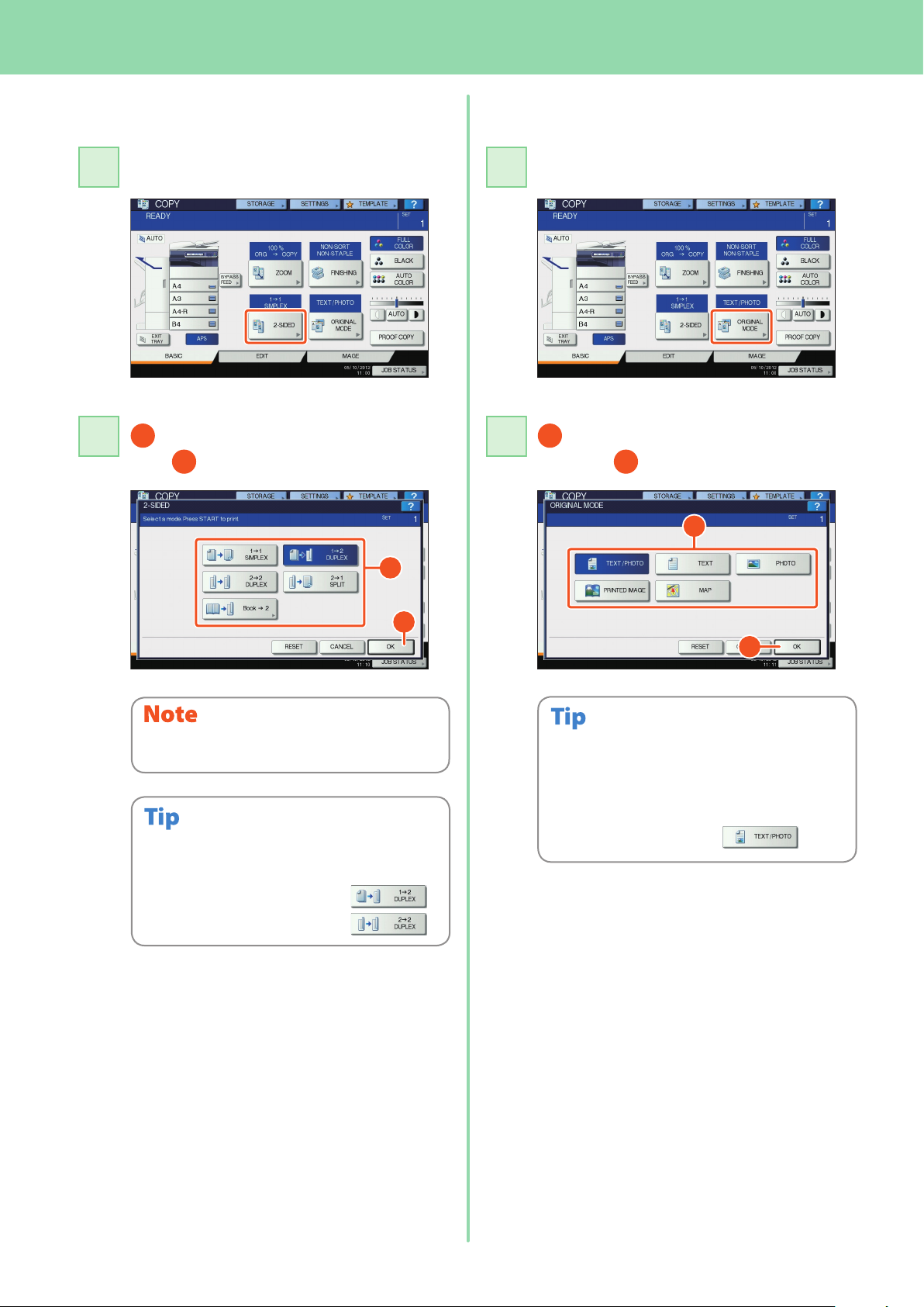
Setting duplex copy
Press [2-SIDED].
Select the desired duplex mode and
then 2 press [OK].
Setting original mode
Press [ORIGINAL MODE].
Select the desired original mode
and then 2 press [OK].
e-STUDIO2051C/2551C: This mode is available only
when the Automatic Duplex Unit is installed.
You can choose from 5 types.
For example, the following settings can be made.
1-sided original to 2-sided copy:
2-sided original to 2-sided copy:
The selectable original mode diers depending on
the color mode. In the full color mode, you can
choose from 5 types.
For example, the following settings can be made.
Originals with text and
photographs mixed:
Page 25
Basic Copying Operation
1
1111
1
33
44
2
1
2
1
22
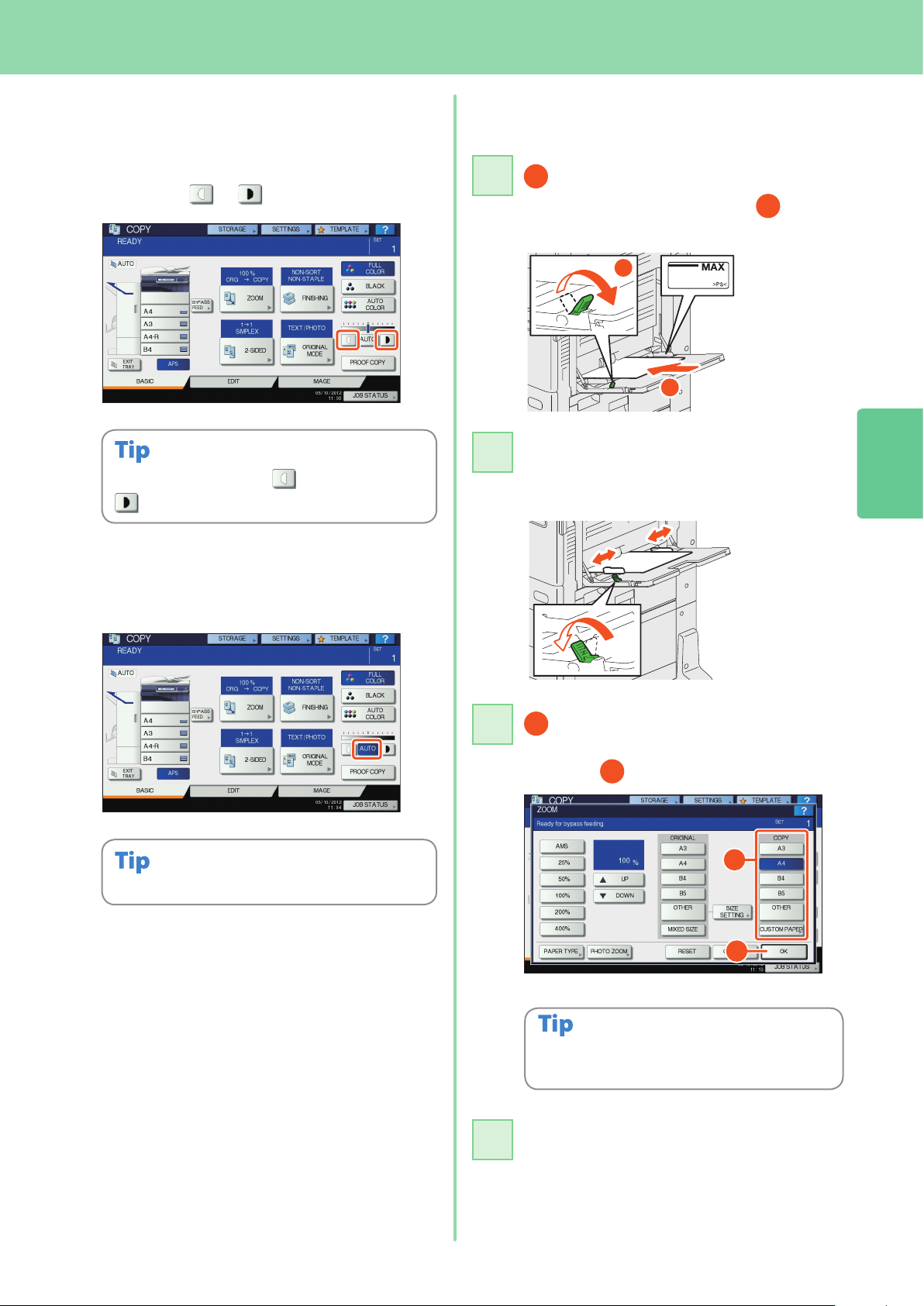
Density adjustment
You can manually adjust the density by
pressing either or .
To lighten the density, press , to darken it, press
.
Bypass copying
Move the paper holding lever
toward the outside and then 2 place
paper face down on the bypass tray.
Align the side guides to the paper
length and then move the paper
holding lever toward the equipment.
2
Press [AUTO] to adjust the density
automatically.
The automatic density adjustment is set by default.
Press the button corresponding to
the size of paper set on the bypass tray
and then 2 [OK].
Press [PAPER TYPE] if the type of the paper you
placed on the bypass tray is other than plain paper.
Press the [START] button. Bypass
copying starts.
23
Page 26
Chapter 2 BASIC OPERATION
11
33
44
22
Basic Fax Operation
The basic procedures for sending a fax, such as specifying fax numbers in the address book or setting the transmission
conditions, are as follows.
Sending a fax
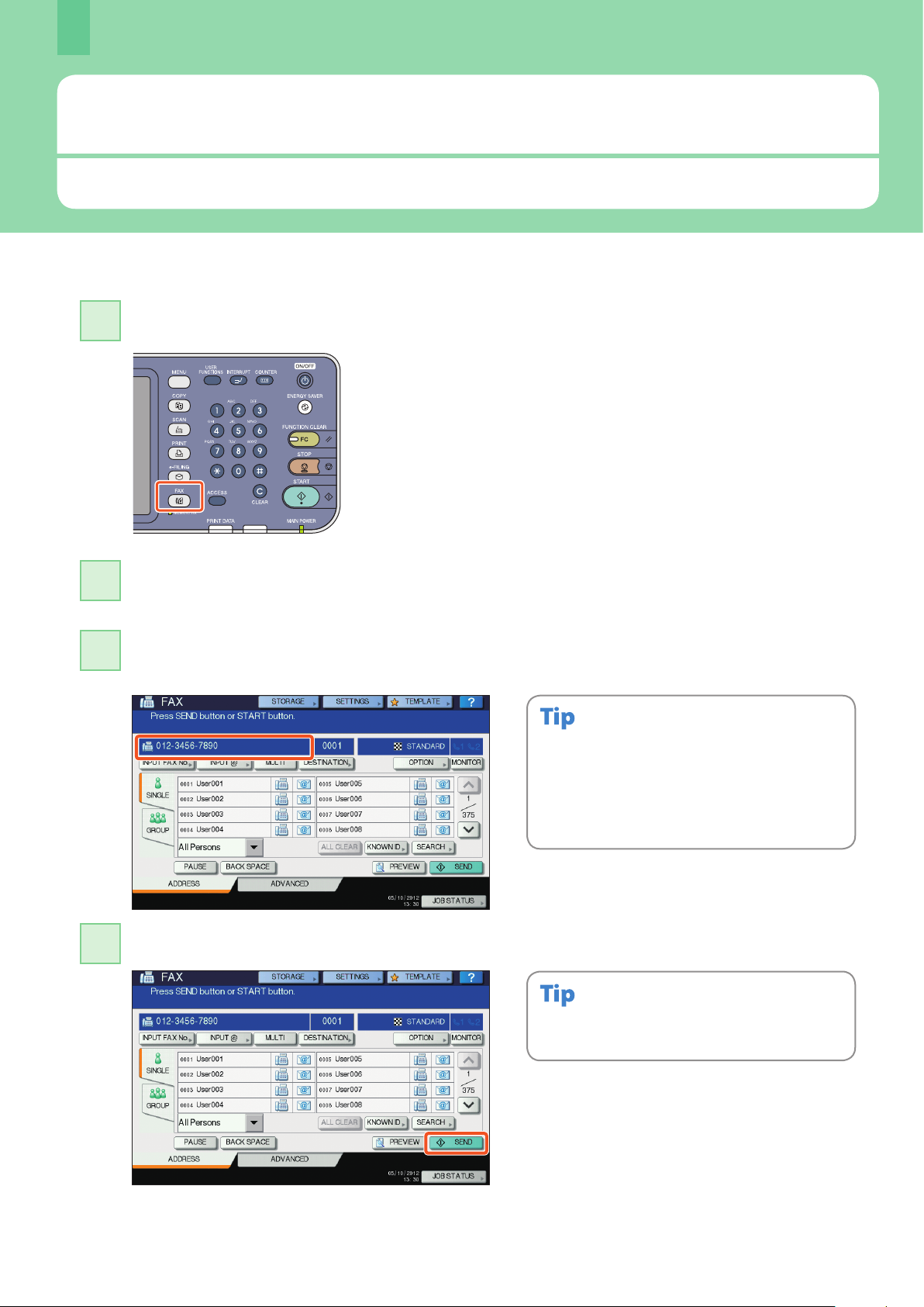
Press the [FAX] button on the control panel.
Place the original(s).
& P.16 “Placing originals” in this manual
Key in the fax number of the recipient by pressing [INPUT FAX No.] on the touch panel or
the digital keys on the control panel.
If you make a mistake when entering a fax number,
press [BACK SPACE] on the touch panel to delete them
one by one.
Or press the [CLEAR] button on the control panel or
[CLEAR] on the touch panel to delete all the numbers
you entered.
Press [SEND] on the touch panel. The fax starts being sent.
Alternatively, you can press the [START] button on the
control panel to send a fax.
24
Page 27

Basic Fax Operation
1
11
22
2
1
1
2
1
Specifying recipients in the
address book
Specifying recipients one by one
Press the [SINGLE] tab to display the list of
addresses, and then 2 the recipient’s fax
icon.
Specifying recipients in groups
Conrming recipients
Press [DESTINATION].
The recipient list screen is displayed.
2
Press [GROUP] tab to display the list of the
groups, and then 2 the group name.
You can specify up to a total of 400 recipients (single
•
and group).
To cancel a selected recipient, press it again.
•
Select the recipient you want to delete, and then
press [DELETE].
25
Page 28

Chapter 2 BASIC OPERATION
26
11
22
11
33
1
22
2
3
1
33
Setting the transmission
conditions
Press [OPTION].
The transmission condition setting
screen is displayed. Press or to
switch the pages.
Canceling reserved
transmissions
Press [JOB STATUS].
Press [FAX], 2 select the reserved
transmission you want to delete, and
then 3 press [DELETE].
RESOLUTION: Set the resolution based on the
neness of the original.
ORIGINAL SIZE: Set the scan size of the original.
After each item is set, press [OK].
Press [DELETE] on the conrmation
screen. The reserved transmission is
deleted.
Page 29

Basic Fax Operation
11
1
22
33
1
2
11
22
33
1
2
2
1
Checking communication
status (log)
Press [JOB STATUS].
Select the [LOG] tab and then 2
press [SEND].
Registering recipients
Press the [USER FUNCTIONS] button on
the control panel and then [ADDRESS]
on the touch panel.
2
1 Press an open button to create a
new recipient and then 2 [ENTRY].
Press [RECEIVE] to check the fax reception log.
The communication status list is
displayed. If [OK] is indicated in the
“Status”, the transmission succeeded.
To register recipients in the address book from the
send/receive log screen, select the record in the
send or receive log, and then press [ENTRY].
1 Press each button on the touch
panel to enter the following recipient
information, and then 2 [OK] to
register it.
27
Page 30

Chapter 2 BASIC OPERATION
11
33
44
3
1
2
22
66
55
Basic Scanning Operation
The basic operation of the scanning function, how to store the scanned data in a shared folder and store these data in a
Windows computer is described as follows.
Storing the scanned data in a shared folder
This operation is available only when the hard disk is installed in the equipment.
Press the [SCAN] button on the control
panel.
Place the original(s).
& P.16 “Placing originals” in this manual
Press [FILE] on the touch panel.
1 Set [FILE NAME], 2 FILE FORMAT,
etc. and then 3 press [OK].
Change the scan settings as required.
Press [SCAN] on the touch panel.
Scanning starts.
28
Page 31

Basic Scanning Operation
11
22
33
To store the scanned data of a shared folder in a Windows
computer
This operation is available only when the hard disk is installed in the equipment.
Start up Windows Explorer.
Enter the name of the shared folder, in which the IP address of the equipment and the
scanned data are stored, in the address bar with the following format, and then press the
[Enter] button.
Format: \\[IP address of the equipment] \le_share
e.g.) When the IP address of the equipment is 172.16.16.110, enter
\\172.16.16.110\le_share
in the address bar of Windows Explorer.
2
For the IP address of the equipment, ask your network administrator.
•
It is convenient to make a shortcut of the “le_share” folder, since step 2 can be
•
omitted.
Store the scanned data in a Windows computer.
The scanned data stored in the shared folder will be automatically deleted in 30 days by default.
Be sure to store them in a Windows computer before that.
29
Page 32

Chapter 2 BASIC OPERATION
11
1
33
1
2
55
1
44
2
1
22
Basic e-Filing Operation
e-Filing is a function to store documents in the hard disk of the equipment, they can then be printed as required.
Storing documents
The originals are stored as e-Filing documents in the equipment.
This operation is available only when the hard disk is installed in the equipment.
Press the [COPY] button on the control
panel.
Place the original(s).
& P.16 “Placing originals” in this manual
Press [STORAGE] and then 2
[STORE TO E-FILING] on the touch
panel.
Specify the box to be stored and the
document name, and then 2 press
[OK].
When “Print this document?” appears, press [YES] if
you want to do this as well as store it.
Press the [START] button on the control
panel to store the documents.
30
You can store documents not only by copying them but also by scanning them or using the printer driver. For details, refer to the
following guides:
& Scanning Guide (PDF): “Chapter 2: BASIC OPERATION” - “Scan to e-Filing”
& Printing Guide (PDF): “Chapter 2: PRINTING FROM WINDOWS” - “Printing with the Best Functions for Your Needs”
Page 33

11
Printing Documents
1
33
2
1
22
The procedure for printing documents stored in e-Filing is as follows.
This operation is available only when the hard disk is installed in the equipment.
Press the [e-FILING] button on the control panel.
Basic e-Filing Operation
2
Select the box on the touch panel that contains the document you want to print.
Select the document you want to print, and then 2 press [PRINT]. Printing starts.
Selected documents can be previewed in thumbnailed form.
Selected documents can be deleted from e-Filing.
This enables you to make print settings, such as selecting the duplex printing mode or adding page
numbers.
Specied pages of the document can be printed for conrmation.
31
Page 34

Chapter 2 BASIC OPERATION
11
33
1
22
44
1
2
Basic Printing Operation
The basic operation of the printer function is as follows. This is for printing from a Windows computer with a Universal Printer 2
driver which needs to be installed in advance.
Select [Print] in the [File] menu of the application.
Select the printer driver of the equipment, and then 2 click [Preferences] ([Properties]).
Set the print options as required and click [OK].
Click [Print] ([OK]). Printing starts.
To install the printer driver in a Windows computer, refer to
the following guide:
& P.17 “Installing Client Software” in this manual
& Software Installation Guide (PDF): “Chapter 3:
INSTALLING PRINTER DRIVERS FOR WINDOWS”
To install the printer driver in a Macintosh computer, refer to
the following guide:
& Software Installation Guide (PDF): “Chapter 4:
INSTALLING PRINTER DRIVERS FOR MACINTOSH”
32
Page 35

Setting Universal Printer 2 driver
2IN1 4IN1
Basic Printing Operation
To specify paper size or number of copy sets
Click the [Basic] tab in the property dialog box of the printer driver.
To specify 2-sided printing or N-up printing
Click the [Finishing] tab in the property dialog box of the printer driver. If the Finisher is installed, “Staple” or “Hole
Punch” can be selected.
Select “Number of pages per Sheet” to
print several pages on one sheet. The
pages are reduced to t the selected
paper size automatically and printed.
To specify Front cover printing
Click the [Paper Handling] tab in the property dialog box of the printer driver.
To adjust Image Quality
Click the [Image Quality] tab in the property dialog box of the printer driver.
To print with character strings or graphics on the background of the paper
Click the [Eect] tab in the property dialog box of the printer driver.
2
To set not to print blank pages
Click the [Others] tab in the property dialog box of the printer driver.
To print with templates
Click the [Templates] tab in the property dialog box of the printer driver.
33
Page 36

Chapter 2 BASIC OPERATION
4
7
1
5
6
2
3
Basic Menu Operation
Press the [MENU] button on the control panel to use templates and check the print counter.
When the user management function is enabled, log in and press the [MENU] button on the control panel. The menu
screen for a logged in user is displayed.
You can register frequently used templates, a group of templates or the shortcut of the External Interface Enabler.
Registration or deletion of the shortcut can also be enabled in the TopAccess mode. For details, refer to the following
guide:
& TopAccess Guide (PDF): “Chapter 9: [My Account] Tab Page”
1. User name display area
The name of the user logging in is displayed.
2. [EXTENSION] button
This is enabled when the External Interface Enabler is
installed. Contact your service technician or representative
for details.
3. Role Information Displayed Area
Available role information for a user who has logged in is
displayed.
5. [USER] button
The shortcut which a user logging in can employ is
displayed.
6. [PUBLIC] button
The shortcut which all users can employ is displayed.
7. Shortcut display area
The shortcut registered in the menu screen is displayed.
4. Total print counter
The total print counter of the user logging in is displayed.
Available printing numbers are displayed depending on
the settings of the equipment.
According to the authority for each user, the mark or appears on the icons in the role information displayed area.
The functions with the mark cannot be used. Some of the functions with the mark cannot be used.
You can create a template with several functions that are frequently used so that they can be employed whenever you want, thus
•
eliminating the need to perform complicated settings every time. Templates can be used in copying, scanning and sending a fax. For
details, refer to the following guides:
& Copying Guide (PDF): “Chapter 6: TEMPLATES”
& TopAccess Guide (PDF): “Chapter 5: [Registration] Tab Page” - “[Registration] Tab Page Overview”
When the user management function is not used, the public template group and the total print counter are displayed.
•
[USER] and [PUBLIC] are displayed when the user management function is enabled.
•
34
Page 37

Chapter 3
MAINTENANCE
Replacing Toner Cartridge . . . . . . . . . . . . . . . . . . . . . . . . . . . . . . .36
Replacing Waste Toner Box . . . . . . . . . . . . . . . . . . . . . . . . . . . . . .37
Replacing Staple Cartridge . . . . . . . . . . . . . . . . . . . . . . . . . . . . . . 38
Regular Cleaning . . . . . . . . . . . . . . . . . . . . . . . . . . . . . . . . . . . . . . . . 42
Page 38

Chapter 3 MAINTENANCE
1
2
10
3
4
5
6
Replacing Toner Cartridge
When “Install new *** toner cartridge” appears on the touch panel, replace the toner cartridge according to the following
procedures.
Open the front cover.
Remove the color toner cartridge you want to
replace.
Pull the seal straight out in the direction of the
arrow.
Insert the new toner cartridge straight along the
guide until it stops.
36
Shake the new toner cartridge well to loosen the
toner inside.
Never attempt to incinerate toner cartridges.
Dispose of used toner cartridges and waste toner boxes in accordance with local regulations.
Close the front cover pressing both edges.
Page 39

1
2
1
1
2
2
1
3
Y M C K
4
5
6
Replacing Waste Toner Box
Replacing Waste Toner Box
When “Dispose of used toner” appears on the touch panel, replace the waste toner box according to the following procedures.
Open the front cover, and put your ngers in the
waste toner box front grooves, then take it out
toward you pushing down the top latch.
Pull down the 4 green levers located under the
toner cartridges.
Insert the cleaner through the service hole of the
developer to the end.
3
Pull the cleaner back out until the round hole
appears. Repeat this 3 times for each of the 4
colors. When you nish cleaning the LED print
head, return the 4 green levers located under the
toner cartridges.
Take out the LED print head cleaner inside the
cover.
Never attempt to incinerate waste toner boxes.
Dispose of used toner cartridges and waste toner boxes in accordance with local regulations.
Set a new waste toner box, and close the front
cover pressing both edges.
37
Page 40

Chapter 3 MAINTENANCE
1
2
3
4
5
6
Replacing Staple Cartridge
When “Check staple cartridge” appears on the touch panel, replace the staple cartridge according to the following procedures.
Stapler Unit of Saddle Stitch Finisher
Open the front cover of the Finisher.
Take o the staple cartridge.
Install a new staple case into the staple cartridge.
Install the staple cartridge.
38
Take the empty staple case out of the staple
cartridge.
Close the front cover of the Finisher.
Page 41

1
2
3
4
5
Saddle Stitch Unit of Saddle Stitch Finisher
Replacing Staple Cartridge
Open the left cover of the Finisher.
Take o the staple cartridge.
Install new staple cartridge.
3
Close the left cover of the Finisher.
Pull out straight the seal bundling the staples.
39
Page 42

Chapter 3 MAINTENANCE
2
1
1
2
1
2
2
1
3
4
5
6
Stapler Unit of Inner Finisher
Lift up the control panel, and open the front cover
of the Finisher.
Holding the lever, move the nisher to the left
until it comes to a stop.
Take o the staple cartridge.
Push the buttons of both side of the cartridge to
take o the staple case.
40
Open the Hole Punch Unit while pushing the
lever.
Install a new staple case.
Page 43

Replacing Staple Cartridge
7
8
9
10
Install the staple cartridge.
Return the Hole Punch Unit to its original
position.
Carefully return the nisher to its original
position.
3
Close the front cover of the Finisher.
Do not put your hand or ngers on the top of the nisher when closing it.
They could be caught and this could injure you.
41
Page 44

Chapter 3 MAINTENANCE Regular Cleaning
3
4
2
1
Regular Cleaning
Poor quality printing such as uneven and soiled images can be improved by simple cleaning. This section describes the
cleaning methods for the equipment.
Cleaning for the scanning area, original glass, guide and platen sheet
We recommend you to clean the following items weekly, so that the originals can be scanned in unsoiled conditions. Be
careful not to scratch the parts that you are cleaning.
Be careful not to scratch the portions in cleaning.
•
When cleaning the surface of the equipment, do not use such organic solvents as thinner or benzine.
•
- This could warp the shape of the surface or leave it discolored.
When using a chemical cleaning pad to clean it, follow the instruction.
•
1. Scanning area (surface of the long rectangular glass) / 2. Original glass
Wipe it with a soft dry cloth. If there are still stains remaining, wipe clean with a piece of soft cloth which has been moistened
with water and then squeezed well.
Do not use liquids other than water (such as alcohol, organic solvents or neutral detergent).
3. Guide / 4. Platen sheet
Clean the surface as follows depending on the staining.
Clean it with a soft cloth.
•
Clean it with a soft cloth lightly moistened with water.
•
Clean it with a soft cloth lightly moistened with alcohol, and then wipe it with a dry cloth.
•
Clean it with a soft cloth lightly moistened with watered-down neutral detergent, and then wipe it with a dry cloth.
•
42
Page 45

Regular Cleaning
1
1
2
3
4
2
3
2
1
1
4
Cleaning the main chargers and LED print heads
If the inside of the main chargers and the print heads of the LED are dirty, the dirt will be transferred to the copied
image. Clean them following the procedure below.
Open the front cover.
Pull out the cleaner until the mark appears and
return it. Repeat this 3 times for each of the 4
colors.
Put your ngers in the waste toner box front
grooves and take it out toward you pushing down
the top latch, and then clean the LED print heads.
For instructions on how to clean the LED print
heads, see the following:
& P.37 “Replacing Waste Toner Box” (Steps 2 to 6)
3
Close the front cover pressing both edges.
43
Page 46

44
Page 47

Chapter 4
TROUBLESHOOTING
Troubleshooting . . . . . . . . . . . . . . . . . . . . . . . . . . . . . . . . . . . . . . . .46
Page 48

Chapter 4 TROUBLESHOOTING
Additional Drawer Module
Large Capacity Feeder
Reversing Automatic Document Feeder
Job Separator
Paper Feed Pedestal
Troubleshooting
When problems such as paper misfeeds occur, see the following explanation or refer to the Troubleshooting Guide (PDF)
according to & P.48 “References to the Troubleshooting Guide” in this manual.
Symbols and messages appear on the touch panel
Symbols or messages of such as for paper misfeeds
occasionally appear on the touch panel.
For details of the paper misfeed symbols, refer to the
following guide:
& Troubleshooting Guide (PDF): “Chapter 1:
TROUBLESHOOTING FOR THE HARDWARE” - “Clearing a
Paper Misfeed”
For details of the messages on the touch panel, refer to the
following guide:
& Troubleshooting Guide (PDF): “Chapter 1:
TROUBLESHOOTING FOR THE HARDWARE” - “Messages
Displayed on the Touch Panel”
When paper misfeeds occur
When paper misfeeds occur, refer to the guidance displayed on the touch panel of the equipment or refer to the
following guide:
& Troubleshooting Guide (PDF): “Chapter 1: TROUBLESHOOTING FOR THE HARDWARE” - “Clearing a Paper Misfeed”
Covers of the equipment and the options
The covers of the equipment and the options to be opened when paper misfeeds occur are as indicated by the arrows in
the following illustrations.
46
Page 49

Troubleshooting
Covers of the Finisher, the Hole Punch Unit and the Bridge Unit
The covers of the Finisher, Hole Punch Unit and Bridge Unit to be opened when paper misfeeds occur are as indicated by the
arrows in the following illustrations.
The Saddle Stitch Finisher, the Hole Punch Unit and the Bridge Unit
The Inner Finisher and the Hole Punch Unit
Using the Help functions
If you press on the upper right of the touch panel,
explanations of the functions and buttons on the screen
are displayed.
If you press on the lower left of the Help screen,
supplementary information about the functions appears.
4
47
Page 50

Chapter 4 TROUBLESHOOTING
About Troubleshooting Guide
The Troubleshooting Guide (PDF) describes the causes and the troubleshooting of problems when you use the
equipment.
References to the Troubleshooting Guide
Chapter Title Section
When This Screen Is Displayed
Messages Displayed on the Touch Panel
Clearing a Paper Misfeed
Clearing a Staple Jam
Chapter 1 TROUBLESHOOTING FOR THE HARDWARE
Chapter 2 TROUBLESHOOTING FOR COPYING Copying Problems
Chapter 3 TROUBLESHOOTING FOR PRINTING
Chapter 4 TROUBLESHOOTING FOR SCANNING Scanning Problems
Chapter 5 TROUBLESHOOTING FOR e-Filing e-Filing Web Utility Problems
Chapter 6
Chapter 7
Chapter 8
TROUBLESHOOTING FOR NETWORK
CONNECTIONS
CHECKING THE EQUIPMENT STATUS WITH
TopAccess
WHEN SOMETHING IS WRONG WITH THE
EQUIPMENT
Replacing a Toner Cartridge
Replacing the Waste Toner Box
Relling With Staples
Cleaning the Main Chargers and LED Print Heads
Cleaning the Hole Punch Dust Bin
When Printed Sheets Overow from the Exit Tray
Print Job Problems
Printer Driver Problems
Network Connection Problems
Client Problems
Hardware Problems
Locating the Equipment in the Network
LDAP Search and Authentication Problems
Printing Problems (Network Related)
Network Fax (N/W-Fax) Driver Problems
Client Software Authentication Problems
Hardware Status Icons on TopAccess [Device] Tab
Error Messages
Error Codes
When You Think Something Is Wrong With the Equipment
Regular Maintenance
48
Error codes
Press [JOB STATUS] and then the [LOG] tab on the touch
panel; the LOG menu is displayed. The job history and
error codes are displayed in the LOG menu.
For details of the error codes, refer to the following guide:
& Troubleshooting Guide (PDF): “Chapter 7: CHECKING
THE EQUIPMENT STATUS WITH TopAccess” - “Error Codes”
Page 51

Chapter 5
ADVANCED
FUNCTIONS
Advanced Functions . . . . . . . . . . . . . . . . . . . . . . . . . . . . . . . . . . . . 50
Page 52

Chapter 5 ADVANCED FUNCTIONS
(LT)
(LD)
(LT)
(LD)
1 3
5 6
1 3
5 6
YYYY . MM . DD 11:11
1
Advanced Functions
In Chapter 2 in this manual, the basic functions are described. This section describes the advanced functions to help you get
the best out of your equipment.
Examples of the advanced functions describing in this section
Copying dierent-sized originals and
stapling copies
& P.51 in this manual
Copying or scanning originals without
blank sheets
& P.52 in this manual
Storing data in a shared folder as well
as sending a fax
Attaching the scanned data to an E-mail
& P.55 in this manual
Adding date and time to document
les
& P.56 in this manual
Printing a PDF le stored in the USB
device
& P.53 in this manual
Registering frequently used scan
settings in templates
& P.54 in this manual
50
& P.57 in this manual
Printing only allowed data set on the
control panel
& P.58 in this manual
Page 53

(LT)
(LD)
(LT)
(LD)
11
22
1
33
44
COPY FAX SCAN e-FILING PRINT
1
55
66
2
1
2
1
Copying dierent-sized originals and stapling copies
Advanced Functions
The procedure of how to copy 5 sets of
dierent-sized originals (A4 or LT: 1
sheet, A3 or LD: 4 sheets) and staple
the copies is as follows. The Reversing
Automatic Document Feeder and the
Finisher are required.
Place the originals on the Reversing
Automatic Document Feeder.
& P.16 “Placing originals” in this manual
If you want to copy dierent-sized originals and
staple the copies, select only those having the same
width.
Press [ZOOM] on the touch panel.
Press [MIXED SIZE] and then 2 [OK]
on the touch panel.
Press [FRONT STAPLE] and then 2
[OK] on the touch panel.
Key in 5 for the number of copy sets,
and then press the [START] button on
the control panel.
Press [FINISHING] on the touch panel.
5
51
Page 54

Chapter 5 ADVANCED FUNCTIONS
52
1 3
5 6
1 3
5 6
22
33
44
11
11
22
33
1
2
44
55
COPY
FAX
SCAN
e-FILING PRINT
Copying or scanning originals without blank sheets
When scanningWhen copying
Place the originals on the Reversing
Automatic Document Feeder.
& P.16 “Placing originals” in this manual
Place the originals on the Reversing
Automatic Document Feeder.
& P.16 “Placing originals” in this manual
You can copy or scan originals omitting
blank sheets while maintaining the
original page sequence.
Press the [EDIT] tab, and then in the
basic menu for the copying functions.
Press [OMIT BLANK PAGE] and then
[OK].
Press the [START] button on the control
panel. Copying starts.
Press [SCAN SETTING], and then in
the basic menu for the scanning
functions.
Press 1 [ON] in the “OMIT BLANK PAGE”
setting and then 2 [OK].
In the basic menu for the scanning
functions, specify details such as the
destination for saving the data.
Press [SCAN] on the touch panel.
Scanning starts.
Page 55

11
22
1
33
44
COPY FAX SCAN e-FILING PRINT
1
2
Storing data in a shared folder as well as sending a fax
This operation is available only when the hard disk is installed in the equipment.
Advanced Functions
You can store documents in a shared
folder in the equipment or in a
computer connected to the network as
well as sending a fax.
Place the original(s).
& P.16 “Placing originals” in this manual
Press [STORAGE] on the touch panel.
Specify details such as the le name, shared folder and le format and then 2 press
[OK].
5
Specify the recipient and press [SEND]. Sending a fax starts.
53
Page 56

Chapter 5 ADVANCED FUNCTIONS
54
11
1
22
33
44
1
55
66
1
77
1
88
2
1
2
1
2
1
1
2
COPY FAX SCAN e-FILING PRINT
Registering frequently used scan settings in templates
If you register frequently used scan
settings in templates, you can easily
perform scan operations only by
recalling the templates. How to
register scan settings (scan data are
stored in PDF format in a shared folder)
in templates (PUBLIC TEMPLATE
GROUP) is described here.
Press [FILE] on the touch panel.
Select “PDF” in the le format, and
then 2 press [OK].
Change the scan setting as required.
Press [TEMPLATE] on the touch panel,
and then [REGISTRATION] tab.
Press [PASSWORD], enter the
administrator password and press [OK].
Select an empty template button,
and then 2 press [SAVE].
Make the settings such as the
template name, and then 2 press
[SAVE] to complete the registration.
Press [PUBLIC TEMPLATE GROUP] on
the touch panel, and then 2 [OPEN].
Page 57

11
22
1
33
44
55
COPY FAX SCAN e-FILING PRINT
1
2
Attaching the scanned data to an E-mail
Place the original(s).
& P.16 “Placing originals” in this manual
Press [E-MAIL] and then [TO] on the touch panel.
Advanced Functions
The procedure for attaching the
scanned data to an E-mail and sending
it to the specied E-mail address is as
follows.
Specify the E-mail address and then 2 press [OK].
Dene the settings for the le as required and then press [OK].
Press [SCAN] on the touch panel. Scanning starts.
5
55
Page 58

Chapter 5 ADVANCED FUNCTIONS
56
YYYY . MM . DD 11:11
11
1
22
33
1
44
55
1
2
1
2
COPY FAX SCAN e-FILING PRINT
Adding date and time to document les
This operation is available only when the hard disk is installed in the equipment.
The procedure for printing a document
le stored in e-Filing with the date and
time added at the bottom is as follows.
Select the box in which the desired document is stored.
Select the document and then 2 press [SETTINGS].
Press [TIME STAMP].
Press [LOWER] and then 2 [OK].
Press [PRINT] on the touch panel. Printing starts.
Page 59

11
22
33
1
44
COPY FAX SCAN e-FILING PRINT
1
2
Printing a PDF le stored in the USB device
The procedure for printing 1 set of a
PDF le stored in the USB device is as
follows.
This operation is available only when the Front USB Cable is mounted in e-STUDIO2050C/2550C.
Advanced Functions
Connect the USB device to the USB port.
Press the [PRINT] button on the control panel.
Click the pull-down menu, and then select [USB].
Select a PDF le to be printed and then 2 press [PRINT]. Printing starts.
5
Press [SETTINGS], then you can set such as
•
duplex printing and stapling.
The following types of les are also available
•
for printing:
- JPEG le
- PRN le
- PS le
- XPS le
57
Page 60

Chapter 5 ADVANCED FUNCTIONS
1
11
22
33
44
55
1
2
88
2
1
66
77
COPY FAX SCAN e-FILING PRINT
Printing only allowed data set on the control panel
This operation is available only when the hard disk is installed in the equipment.
The procedure for printing only
allowed data set on the control panel is
as follows. This will stop you from
forgetting to remove printed sheets.
Open a le to be printed on a Windows
computer, and then select [Print] from
the le menu of the application.
Select the printer driver of the
equipment, and then click [Preferences]
([Properties]).
Select “Hold Print” for the job type in
the [Basic] tab menu.
Click the pull-down menu, and then
select [HOLD].
Select the user name, and then press
[OK].
Select the le to be printed and then
press [PRINT]. Printing starts.
Click [OK] to return to the print dialog
box and then [Print] ([OK]).
Press the [PRINT] button on the control
panel of the equipment.
58
Page 61

Chapter 6
INFORMATION
ABOUT EQUIPMENT
Items Included in This Product . . . . . . . . . . . . . . . . . . . . . . . . . . . 60
Client Utilities/User Documentation DVD . . . . . . . . . . . . . . . .61
Client Software . . . . . . . . . . . . . . . . . . . . . . . . . . . . . . . . . . . . . . . . . 62
Options . . . . . . . . . . . . . . . . . . . . . . . . . . . . . . . . . . . . . . . . . . . . . . . . .64
Logging in . . . . . . . . . . . . . . . . . . . . . . . . . . . . . . . . . . . . . . . . . . . . . .67
Specications of Equipment . . . . . . . . . . . . . . . . . . . . . . . . . . . . . 70
Specications of Options . . . . . . . . . . . . . . . . . . . . . . . . . . . . . . . .73
Page 62

Chapter 6 INFORMATION ABOUT EQUIPMENT
60
Items Included in This Product
The following items are co-packed with the equipment. Check that you have them all. Contact your service technician or
representative if any are missing or damaged.
Items included in this product
Safety Information The Safety Information describes the necessary precautions for use. For your added
security, be sure to read this booklet rst.
Quick Start Guide (This manual) The Quick Start Guide describes the preparations, basic and advanced usage,
maintenance and regular cleaning of the equipment.
Client Utilities/User Documentation DVD The Client Utilities/User Documentation DVD contains the client software such as the
printer drivers and the utility software. It also contains pdf les of the Operator’s
Manuals such as the Copying Guide and the Troubleshooting Guide. For details, see the
following page:
& P.61 “Client Utilities/User Documentation DVD“ in this manual
Page 63

Client Utilities/User Documentation DVD
Client Utilities/User Documentation DVD
The Client Utilities/User Documentation DVD contains pdf les of the Operator’s Manuals and the following client software
such as the printer drivers and the utility software.
Client software
For Windows Client Software Installer
Universal Printer 2 driver
Universal PS3 printer driver
Universal XPS printer driver
TWAIN driver
File downloader
N/W-Fax driver
AddressBook Viewer
Remote Scan driver
WIA driver
e-Filing Backup/Restore Utility
For Macintosh PPD le for Mac OS X 10.2.8 to Mac OS X 10.3.x
PPD le for Mac OS X 10.4 to Mac OS X 10.7.x
Plug-in for Mac OS X 10.4 or later
For UNIX/Linux UNIX/Linux lter (Solaris, HP-U, AIX, Linux, SCO)
CUPS
Only the following software is available for e-STUDIO2051C/2551C:
- Client Software Installer
- Universal PCL6 printer driver
- TWAIN driver
- N/W-Fax driver
- AddressBook Viewer
- Remote Scan driver
- WIA driver
For installing the client software, refer to the following guide:
& Software Installation Guide (PDF): “Chapter 1: OVERVIEW”
For details of the client software, see the following page:
& P.62 “Client Software” in this manual
6
61
Page 64

Chapter 6 INFORMATION ABOUT EQUIPMENT
Client Software
This section describes the outlines of the client software of the equipment. It is necessary to install software except e-Filing
Web utility and TopAccess in the computer before it is used.
Client software for the printing functions
Universal Printer 2 driver This Universal Printer 2 driver is installed with the Recommended Installation. This driver is generally
used. For details, refer to the following guides:
& Software Installation Guide (PDF): “Chapter 2: RECOMMENDED INSTALLATION” or “Chapter 3:
INSTALLING PRINTER DRIVERS FOR WINDOWS”
& P.32 “Basic Printing Operation” in this manual
& Printing Guide (PDF): “Chapter 2: PRINTING FROM WINDOWS”
Universal PS3 printer driver
Universal XPS printer driver This printer driver enables you to print documents from the WPF applications created for Windows
PPD le for Macintosh This printer driver enables you to print documents from Macintosh computers (Mac OS X 10.2.8 to
UNIX/Linux lter UNIX/Linux lter enables you to print documents from the UNIX/Linux workstation. For details, refer
CUPS CUPS le enables you to set up the CUPS print system from UNIX/Linux workstation. For details, refer
This driver enables you to print documents in the high quality mode with applications such as
Adobe Systems Incorporated. For details, refer to the following guides:
& Software Installation Guide (PDF): “Chapter 2: RECOMMENDED INSTALLATION” or “Chapter 3:
INSTALLING PRINTER DRIVERS FOR WINDOWS”
& Printing Guide (PDF): “Chapter 2: PRINTING FROM WINDOWS”
Vista or Windows 7. For details, refer to the following guides:
& Software Installation Guide (PDF): “Chapter 2: RECOMMENDED INSTALLATION” or “Chapter 3:
INSTALLING PRINTER DRIVERS FOR WINDOWS”
& Printing Guide (PDF): “Chapter 2: PRINTING FROM WINDOWS”
Mac OS X 10.7). For details, refer to the following guides:
& Software Installation Guide (PDF): “Chapter 4: INSTALLING PRINTER DRIVERS FOR MACINTOSH”
& Printing Guide (PDF): “Chapter 3: PRINTING FROM Macintosh”
to the following guides:
& Software Installation Guide (PDF): “Chapter 5: INSTALLING PRINTER DRIVERS FOR UNIX/Linux”
& Printing Guide (PDF): “Chapter 4: PRINTING FROM UNIX/Linux”
to the following guide:
& Software Installation Guide (PDF): “Chapter 5: INSTALLING PRINTER DRIVERS FOR UNIX/Linux”
62
e-STUDIO2051C/2551C: Only the Universal PCL6 printer driver is available.
Client software for the scanning functions
Remote Scan driver This driver enables you to scan documents remotely and obtain scanned data as an image in the
applications supporting TWAIN on Windows computers. For details, refer to the following guide:
& Software Installation Guide (PDF): “Chapter 2: RECOMMENDED INSTALLATION” or “Chapter 6:
INSTALLING SCAN DRIVER AND UTILITIES”
WIA driver This driver enables you to scan documents remotely and obtain scanned data as an image in the
applications supporting WIA (Windows Imaging Acquisition) on Windows computers. For details,
refer to the following guides:
& Software Installation Guide (PDF): “Chapter 2: RECOMMENDED INSTALLATION” or “Chapter 6:
INSTALLING SCAN DRIVER AND UTILITIES”
& Scanning Guide (PDF): “Chapter 5: OTHER SCANNING METHODS”
Page 65

Client Software
Client software for the e-Filing functions
TWAIN driver This driver enables you to obtain documents stored in e-Filing as an image in application supporting
TWAIN on Windows computers. For details, refer to the following guide:
& Software Installation Guide (PDF): “Chapter 2: RECOMMENDED INSTALLATION” or “Chapter 6:
INSTALLING SCAN DRIVER AND UTILITIES”
File downloader File downloader enables you to obtain documents stored in e-Filing as an image in your Windows
computer. For details, refer to the following guide:
& Software Installation Guide (PDF): “Chapter 2: RECOMMENDED INSTALLATION” or “Chapter 6:
INSTALLING SCAN DRIVER AND UTILITIES”
e-Filing Web utility This utility enables you to operate or make settings for e-Filing using a browser on your computer.
Since this utility has been already installed to the equipment, enter the IP address of the equipment
into a browser and turn on the power. For details, refer to the following guide:
& e-Filing Guide (PDF): “Chapter 3: OVERVIEW ON e-Filing WEB UTILITY”
e-Filing Backup/Restore
Utility
e-STUDIO2051C/2551C: Only the TWAIN driver is available.
This utility enables you to back up and restore the data stored in e-Filing. For details, refer to the
following guide:
& Software Installation Guide (PDF): “Chapter 8: INSTALLING e-Filing BACKUP/RESTORE UTILITIES”
Client software for the network management functions
TopAccess TopAccess enables you to view the device information, display logs, create templates and an address
book, and manage the equipment using a browser. Since TopAccess has been already installed to
the equipment, enter the IP address of the equipment into a browser and turn on the power. For
details, refer to the following guide:
& TopAccess Guide (PDF): “Chapter 1: OVERVIEW”
Client software for the network fax functions
N/W-Fax driver This driver enables you to send faxes or Internet faxes from your computer. For details, refer to the
following guides:
& Software Installation Guide (PDF): “Chapter 2: RECOMMENDED INSTALLATION” or “Chapter 7:
INSTALLING NETWORK FAX UTILITIES”
& Network Fax Guide (PDF): “Chapter 1: OVERVIEW”
AddressBook Viewer This viewer enables you to manage the address book (such as fax numbers and E-mail addresses)
and upload the address book from your computer to the equipment. For details, refer to the
following guide:
& Software Installation Guide (PDF): “Chapter 2: RECOMMENDED INSTALLATION” or “Chapter 7:
INSTALLING NETWORK FAX UTILITIES”
6
63
Page 66

Chapter 6 INFORMATION ABOUT EQUIPMENT
e-STUDIO2050C/2550C , e-STUDIO2051C/2551Ce-STUDIO2050C/2550C , e-STUDIO2051C/2551C
e-STUDIO2051C/2551C
e-STUDIO2050C/2550C
76 8 9
3
5
4
12
13
10 11
1 2
Options
The following options are sold separately, and upgrade the performance of the equipment if installed. For details, contact your
service technician or representative.
1. Original Cover (KA-1640PC)
This is used to hold an original.
2. Reversing Automatic Document Feeder
(MR-3024)
This unit automatically feeds a stack of originals one by
one to have them copied.
3. Bridge Unit (KN-2550)
This unit acts as a relay for the Finisher and this equipment
4. Job Separator (MJ-5004)
Enables Faxes, copies and prints to be output onto
separate paper trays.
5. Automatic Duplexing Unit (MD-0105)
This unit makes copies on both sides of the paper.
6. Paper Feed Unit (MY-1040)
Use this to add one more drawer to the equipment.
7. Paper Feed Pedestal (KD-1032)
This pedestal enables you to install the Additional Drawer
Module.
8. Large Capacity Feeder (KD-1031)
This feeder enables you to feed up to 2000 sheets (80 g/m2
or 20 lb. Bond) of A4 or LT paper.
9. Additional Drawer Module (MY-1039)
This drawer can be added to the Paper Feed Pedestal.
10. Saddle Stitch Finisher (MJ-1037)
This Finisher enables saddle stitching, in addition to sort/
.
group nishing and stapling. The Hole Punch Unit can be
installed in this Finisher. The Bridge Unit is required for the
installation of this Finisher.
11. Hole Punch Unit (MJ-6008)
This unit enables you to punch holes on printed sheets.
Install it in the Saddle Stitch Finisher to use it.
12. Inner Finisher (MJ-1036)
This Finisher enables sort/group nishing and stapling
The Hole Punch Unit can be installed in this Finisher.
13. Hole Punch Unit (MJ-6007)
This unit enables you to punch holes on printed sheets.
Install it in the Job Separator to use it.
64
Page 67

Other options available are as follows. Contact your service technician or representative for details.
Options
Work Table (KK-4550)
This is a small table for placing originals while the equipment is
being operated.
Installed on the right-hand side of the equipment.
FAX Unit (GD-1320)
This is a unit for using the equipment as a Fax machine.
Installed in the rear side of the equipment.
2nd Line for FAX Unit (GD-1260)
This unit enables you to add a line to the Fax, making a 2nd line
available.
Installed inside of the equipment.
•
The FAX Unit is required.
•
Desk (MH-2050)
This is a desk for the equipment.
Accessible Arm (KK-2550)
This enables a user in a wheelchair to close the Reversing
Automatic Document Feeder while emaining seated.
& P.66 “How to use the Accessible Arm” in this manual
Operator’s Manual Pocket (KK-1660)
Keep the manual in this pocket.
Wireless LAN Module (GN-1060)
This module enables the equipment to be used in a wireless LAN
environment.
Installed inside of the equipment.
•
The Antenna is required.
•
The equipment cannot be connected to the wireless and wired
•
LAN at the same time.
Antenna (GN-3010)
This is used when the Wireless LAN Module is installed.
e-BRIDGE ID Gate (KP-2004/KP-2005)
You can log in and use the equipment simply by holding the IC
card over the e-BRIDGE ID Gate.
Installed on the right-hand side of the equipment.
•
This cannot be installed with the Work Table at the same time.
•
Data Overwrite Enabler (GP-1070)
This is an enabler to erase the data stored temporarily when
copying, printing, scanning, faxing, Internet Fax or network Fax
is performed. It overwrites temporarily stored data with random
data.
IPsec Enabler (GP-1080)
This enables the IPsec function in this equipment.
Hardcopy Security Kit (GP-1190)
This enables Hardcopy Security Printing and you can track the
security pattern information.
Meta Scan Enabler (GS-1010)
This enables the Meta Scan function in this equipment.
External Interface Enabler (GS-1020)
This enables the EWB function in this equipment.
Unicode Font Enabler (GS-1007)
This enables printing from the SAP environment using Unicode
font with this equipment.
Front USB Cable (GR-1140)
This enables to connect a USB media in this equipment.
Hard Disk Kit (GE-1220)
This enables to store the data,etc.
Depending on the model, options have been already installed and the functions can be used.
The following options are exclusive for e-STUDIO2050C/2550C:
- Wireless LAN Module (GN-1060)
- Antenna (GN-3010)
- Data Overwrite Enabler (GP-1070)
- IPsec Enabler (GP-1080)
- Hardcopy Security Kit (GP-1190)
- Meta Scan Enabler (GS-1010)
- External Interface Enabler (GS-1020)
- Unicode Font Enabler (GS-1007)
- Front USB Cable (GR-1140)
- Hard Disk Kit (GE-1220)
6
65
Page 68

Chapter 6 INFORMATION ABOUT EQUIPMENT
1
2
1
2
How to use the Accessible Arm
A person in a wheelchair can close the Reversing Automatic Document Feeder using the Accessible Arm.
Store it near the equipment.
Hold the Accessible Arm.
Hook the Accessible Arm on the right-hand side of
the Reversing Automatic Document Feeder to
close it.
Do not store the Accessible Arm by attaching it on the equipment.
66
Page 69

Logging in
Logging in
When the equipment is controlled under department or user management, copying and other functions can be performed if
you log in according to the following procedure.
Department management
You can restrict users or manage copy volumes made by an individual group or department in your company using the
department codes. When the equipment is controlled under the department code, turn the power on and enter the
code.
When the power of the equipment is turned ON, the following menu appears.
This menu also appears when the [ACCESS] button on the control panel is pressed or the automatic function clear has
worked.
Automatic function clear:
This function returns all settings to default without the need to press the [FUNCTION CLEAR] button on the control panel. It works
•
when a specied period of time has passed since the last paper exit or the last entry of any button. When department or user
management is being used, the display returns to the department code or user information input menu. When they are not being
used, the display returns to the basic menu for the copying function.
The period is set at 45 seconds by default at the time of installation of the equipment. To change the setting, refer to the following
•
guide:
& MFP Management Guide (PDF): “Chapter 2: SETTING ITEMS (ADMIN)” - “Setting General Functions”
When connecting to equipment with department or user management enabled using client software, you may need to log in. For
•
details, ask your administrator.
Key in a department code (max. 63 digits) previously registered and press [OK] on the touch panel. The menu will switch
and the equipment will be ready for use.
If the department code keyed in is incorrect, the menu does not change. Key in the correct one.
After the operation
To prevent unauthorized use of the equipment, return the display to the department code input menu by following
either of the procedures below after you nish all operations.
Press the [ACCESS] button on the control panel.
•
Press the [FUNCTION CLEAR] button on the control panel twice.
•
6
67
Page 70

Chapter 6 INFORMATION ABOUT EQUIPMENT
User management
You can restrict users or manage available functions and past records by means of user management. When the
equipment is managed under this function, turn the power ON and enter the information required (e.g. user name,
password). The menu for entering user information also appears when you press the [ACCESS] button on the control
panel or automatic function clear has worked. Enter the information according to the procedure below.
If you enter an invalid password several times, you may not log in for a certain period since it will be regarded as an unauthorized
access.
When “User account is locked” or “User Name and Password are not recognized.” appears and logging in cannot be performed, ask your
administrator.
If a guest user is enabled in the user management function, [GUEST] is displayed on the touch panel. Press [GUEST] to log in as a guest
user. For the types of functions available, consult the administrator.
MFP local authentication
Windows Domain authentication
LDAP authentication
68
Page 71

Logging in
11
22
33
44
55
66
77
The menu for user authentication
appears.
MFP local authentication
Windows Domain authentication, LDAP authentication
Press [PASSWORD].
Enter the password (maximum 64
letters) and then press [OK].
The domain name previously set by the network
administrator is displayed in [DOMAIN]. For LDAP
authentication, the LDAP server name is displayed in
[LDAP] instead of [DOMAIN].
If the displayed domain name or LDAP server name
is not yours, press to select one belonging to
you.
Press [USER NAME].
Enter the user name (maximum 128
letters) and then press [OK].
Press [OK].
The equipment becomes being ready to
perform copying and other functions.
6
69
Page 72

Chapter 6 INFORMATION ABOUT EQUIPMENT
Specications of Equipment
This section describes the types of acceptable paper, sheet capacity of each feeder and the specications of the equipment.
Acceptable paper
Feeder Media type Weight Maximum sheet capacity Paper size
A/B format:
A3, A4, A4-R, A5-R, B4, B5, B5-R,
FOLIO
LT format:
LD, LG, LT, LT-R, ST-R, COMP, 13"
LG, 8.5" SQ
K format:
8K, 16K, 16K-R
A/B format:
A3, A4, A4-R, A5-R, B4, B5, B5-R,
FOLIO
LT format:
LD, LG, LT, LT-R, ST-R, COMP, 13"
LG, 8.5" SQ
K format:
8K, 16K, 16K-R
A4, LT
A/B format:
A3, A4, A4-R, A5-R, A6-R, B4,
B5, B5-R, FOLIO
LT format:
LD, LG, LT, LT-R, ST-R, COMP, 13"
LG, 8.5" SQ
K format:
8K, 16K, 16K-R
Drawer
Paper Feed Unit,
Paper Feed
Pedestal,
Additional
Drawer Module
Large Capacity
Feeder
PLAIN,
RECYCLED PAPER
THICK1
PLAIN,
RECYCLED PAPER
THICK1
PLAIN,
RECYCLED PAPER
PLAIN,
RECYCLED PAPER
THICK1
60 - 105 g/m
2
16 - 28 lb. Bond
106 - 163 g/m
2
29 lb. Bond - 90 lb. Index
60 - 105 g/m
2
16 - 28 lb. Bond
106 - 163 g/m
2
29 lb. Bond - 90 lb. Index
64 - 105 g/m
2
17 - 28 lb. Bond
60 - 105 g/m
2
16 - 28 lb. Bond
106 - 163 g/m
2
29 lb. Bond - 90 lb. Index
277 sheets (64 g/m2, 17 lb. Bond)
250 sheets (80 g/m2, 20 lb. Bond)
231 sheets (81 - 105 g/m2, 21 - 28
lb. Bond)
69 sheets
600 sheets (64 g/m2, 17 lb. Bond)
550 sheets (80 g/m2 , 20 lb. Bond)
500 sheets (81 - 105 g/m2, 21 - 28
lb. Bond)
300 sheets
2360 sheets (64 g/m2, 17 lb. Bond)
2000 sheets (80 g/m2, 20 lb. Bond)
1660 sheets (81 - 105 g/m2, 21 - 28
lb. Bond)
100 sheets (64 - 80 g/m2) (17 - 20
lb. Bond)
80 sheets (81 - 105 g/m2) (21 - 28
lb. Bond)
40 sheets
70
Bypass tray
*1
THICK2
TRANSPARENCY
ENVELOPE
TAB PAPER
*1, *3, *4
*1
164 - 209 g/m
91 - 110 lb. Index
*1
2
30 sheets
—
—
— —
30 sheets A3, A4, LD, LT
1 sheet
Non-Standard size:
Length: 100 - 297 mm
(3.9 - 11.7"),
Width: 148 - 432 mm (5.8 - 17")
DL: 110 mm x 220 mm
(4.33" x 8.66")
COM10: 105 mm x 241 mm
(4.13" x 9.49")
Monarch: 98 mm x 190 mm
(3.86" x 7.48")
CHO-3: 120 mm x 235 mm
(4.72" x 9.25")
YOU-4: 105 mm x 235 mm
(4.13" x 9.25")
A4, LT
Page 73

Specications of Equipment
*1 Duplex copying is not available.
*2 For making copies on the sticker labels, select “THICK 2” for the paper type.
*3 Printing on the back side of an envelope is possible only when the envelope is not a self-sealing envelope.
*4 When the Saddle Stitch Finisher is installed, the envelope exits to the exit tray of the equipment. When the Inner Finisher is installed, the envelope exits
to the receiving tray of the nisher.
Recommended paper for each media type
Media Type Toshiba recommendations/Manufacturer Weight
A/B format: TGIS Paper/Mondi
PLAIN
THICK1
THICK2
TRANSPARENCY
ENVELOPE
*1 Only Toshiba-recommended OHP lm should be used. Using any other lm may cause a malfunction.
*2 Automatic duplex copying is not available.
*3 Printing on the back side of an envelope is possible only when the envelope is not a self-sealing envelope.
*3
LT format: TIDAL MP/Hammermill
A/B format: Color Copy/Mondi
LT format: Laser Print/Hammermill, Color Copy Paper/Hammermill
A/B format: Color Copy/Mondi
LT format: Laser Print/Hammermill, Color Copy Paper/Hammermill
A/B format: ColorCopy/mondi 200 g/m
A/B format: 3478/Zweckform-Avery
LT format: 5165/Avery
A/B format: CG3700/3M
*1, *2
LT format: BG72/Folex
Westvaco Columbian CO138,
Mailwell No. 553
80 g/m2, 20 lb. Bond
90 g/m2, 24 lb. Bond
100 g/m2, 28 lb. Bond
120 g/m2, 32 lb. Bond
160 g/m2, 60 lb. Cover
2
—
—
—
6
71
Page 74

Chapter 6 INFORMATION ABOUT EQUIPMENT
e-STUDIO2050C/2550C, e-STUDIO2051C/2551C Specications
Model name
Type Desktop type
Original glass Fixed
Printing (copying) system Indirect electrophotographic method
Developing system 2-component magnetic brush developing
Fixing method Roller fusing
Photosensor type OPC
Original scanning system
Original scanning sensor Linear CCD sensor
Scanning light source LED
Scanning 600 dpi x 600 dpi
Resolution
Acceptable originals Sheets, books
Acceptable original size Max. A3 or LD
Acceptable copy
paper size
Acceptable copy
paper weight
First copy time
(A4 or LT
portrait)
Continuous copy speed Refer to the Copying Guide.
Multiple copying Up to 999 sheets (digital key entry)
Excluded image
width
Reproduction
ratio
Paper supply
Exit tray loading capacity Approx. 550 sheets (80 g/m2, 20 lb. Bond)
Toner density adjustment Magnetic auto-toner system + Pixel count system
Exposure control Automatic plus manual selection from 11 exposure step
USB interface USB 2.0 (Hi-Speed)
Environment (for normal use) Temperature: 10 ° - 30 °C (50 ° - 86 °F), Humidity: 20 - 85% (No Condensation)
Power requirements and Power
consumption
(including optional equipments)
Dimensions (equipment only) 575 mm (22.6") (W) x 590 mm (23.2") (D) x 662 mm (26.0") (H)
Weight
Space occupied (equipment only) 964 mm (38") (W) x 730 mm (28.7") (D)
Storage capacity
• This specication varies depending on the printing conditions and the environment.
• Specications and appearance are subject to change without notice in the interest of product improvement.
Writing
Drawer
Bypass
Drawer 60 - 163 g/m2 (16 lb. Bond - 90 lb. Index)
Bypass Continuous paper feed / Single paper feed: 60 - 209 g/m2 (16 lb. Bond - 110 lb. Index)
Black-and-white Approx. 8.2 seconds
Color Approx. 10.3 seconds
Black-and-white
Color
Printer (Blackand-white/Color)
Actual size 100±0.5%
Zoom
Drawer Approx. 250 sheets (80 g/m2, 20 lb. Bond)
Bypass Approx. 100 sheets (80 g/m2, 20 lb. Bond)
FC-2050C/2550C
FC-2051C/2551C
Flat surface scanning system
(When the Reversing Automatic Document Feeder is installed: Fixed scanning system by
feeding the original)
Black-and-white: 600 dpi x 1200 dpi, 1 bit
Color, Grayscale: 600 dpi x 600 dpi, 5 bits
A3, A4, A4-R, A5-R, B4, B5, B5-R, FOLIO, LD, LG, LT, LT-R, ST-R, COMP, 13"LG, 8.5"SQ, 8K, 16K,
16K-R
Paper size within 100 - 297 mm (3.94" - 11.69") (Length),
148 - 432 mm (5.83" - 17.01") (Width)
Leading edge: 4.2 mm +2.8 mm - 1.2 mm (0.17" +0.11" -0.05"),
Trailing edge: 3.0±2.0 mm (0.12"±0.08"),
Both edges: 2.0±2.0 mm (0.08"±0.08")
Leading edge: 5.0 mm +2.0 mm (0.20"±0.08"),
Trailing edge: 3.0±2.0 mm (0.12"±0.08"),
Both edges: 2.0±2.0 mm (0.08"±0.08")
Leading edge: 4.2 mm +2.8 mm - 1.2 mm (0.17" +0.11" -0.05"),
Trailing edge: 4.2 mm +1.2 mm -2.8 mm (0.17" +0.05" -0.11"),
Both edges: 4.2±2.0 mm (0.08"±0.08")
25 - 400% (in 1% increments)
For the Reversing Automatic Document Feeder 25 - 200% (in 1% increments)
AC 220-240 V±10%, 8 A (50/60 Hz): 1.6 kW or less
AC 120 V±10%, 12 A (50/60 Hz): 1.5 kW or less
e-STUDIO2050C/2550C: Approx. 57 kg (125.7 lb.) (equipment including developer and drum)
e-STUDIO2051C/2551C: Approx. 56 kg (123.5 lb.) (equipment including developer and drum)
For e-STUDIO2050C/2550C (when hard disk is installed): Max. 1000 sheets or until the
memory is full (Toshiba's own chart)
For e-STUDIO2050C/2550C (when hard disk is not installed) or e-STUDIO2051C/2551C: Until
the memory is full
72
Page 75

Specications of Options
Specications of Options
This section describes the specications of the options sold separately. For details other than the specications, see & P.64
“Options” in this manual.
Reversing Automatic Document Feeder
Model name MR-3024
Copy sides 1-side, Duplex
Number of originals
(A4 or LT)
Feeding speed 45 sheets/min. (600 dpi)
Acceptable originals
Paper weight 1-sided original: 35 - 157 g/m2, 9.3 - 41.8 lb., 2-sided original: 50 - 157 g/m2, 13.3 - 41.8 lb.
Power source DC 24 V (supplied from the equipment)
Dimensions 575 mm (22.6") (W) x 528 mm (20.8") (D) x 135 mm (5.3") (H)
Weight Approx. 12.5 kg (27.6 lb.)
Power consumption 49.5 W max.
100 originals (35 - 80 g/m2, 9.3 - 20 lb. Bond) or 16 mm/0.63" or less in height (more than 80 g/m2, 20 lb. Bond)
A3, A4, A4-R, A5-R, B4, B5, B5-R, FOLIO, LD, LG, LT, LT-R, ST-R, COMP
(A5 and ST size are not acceptable.)
Large Capacity Feeder
Model name KD-1031
Acceptable paper
size
Paper weight 60 - 105 g/m2, 16-28 lb. Bond
Maximum capacity 2000 sheets (80 g/m2, 20 lb. Bond) (Height: approx. 110 mm or 4.3" x 2)
Power source DC 5 V, DC 24 V (supplied from the equipment)
Dimensions 668 mm (26.3") (W) x 735 mm (28.9") (D) x 292 mm (11.5") (H) (incl. Stabilizer)
Weight Approx. 26 kg (57.3 lb.)
A4 or LT
Paper Feed Pedestal (1 drawer type)
Model name KD-1032
Acceptable paper
size
Paper weight 60 - 209 g/m2 (16 lb. Bond - 110 lb. Index)
Maximum capacity 550 sheets (80 g/m2, 20 lb. Bond)
Power source DC 5 V, DC 24 V (supplied from the equipment)
Dimensions 660 mm (26") (W) x 701 mm (27.6") (D) x 292 mm (11.5") (H) (incl. Stabilizer)
Weight Approx. 21 kg (46.3 lb.)
A3, A4, A4-R, A5-R, B4, B5, B5-R, FOLIO, LD, LG, LT, LT-R, ST-R, COMP, 8.5"SQ, 13"LG, 8K, 16K, 16K-R (A5, ST and
non-standard size are not acceptable.)
Additional Drawer Module
Model name MY-1039
Acceptable paper
size
Paper weight 60 - 209 g/m2 (16 lb. Bond - 110 lb. Index)
Maximum capacity 550 sheets (80 g/m2, 20 lb. Bond), 500 sheets (105 g/m2, 24 or 28 lb. Bond)
Weight Approx. 9 kg (19.8 lb.)
A3, A4, A4-R, A5-R, B4, B5, B5-R, FOLIO, LD, LG, LT, LT-R, ST-R, COMP, 8.5"SQ, 13"LG, 8K, 16K, 16K-R (A5, ST and
non-standard size are not acceptable.)
6
73
Page 76

Chapter 6 INFORMATION ABOUT EQUIPMENT
Paper Feed Unit
Model name MY-1040
Acceptable paper
size
Paper weight 60 - 163 g/m2 (16 lb. Bond - 90 lb. Index)
Maximum capacity 550 sheets (80 g/m2, 20 lb. Bond)
Power source DC 5 V, DC 24 V (supplied from the equipment)
Dimensions 575 mm (22.6") (W) x 583 mm (23.0") (D) x 163 mm (6.4") (H) (excl. Stabilizer)
Weight Approx. 9.6 kg (21.2 lb.)
A3, A4, A4-R, A5-R, B4, B5, B5-R, FOLIO, LD, LG, LT, LT-R, ST-R, COMP, 8.5"SQ, 13"LG, 8K, 16K,
16K-R (Non-standard size are not acceptable.)
Saddle Stitch Finisher
Model name MJ-1037
Type Floor type (Console type)
Acceptable paper size A3, A4, A4-R, A5-R, A6-R, B4, B5, B5-R, FOLIO, LD, LG, LT, LT-R, ST-R, COMP, 8.5" SQ, 13"LG, 8K, 16K, 16K-R
Acceptable paper
weight
Number of sheets
stapled at a time
Stapling position Front, Rear, Double
Stitching capacity
(Including 1 cover (106 209g/m
110 lb. Index))
Power source Supplied from the equipment
Dimensions 409 mm (16.1") ( W) x 624 mm (24.57") (D) x 961 mm (37.83") (H) (When the sub-tray is retracted)
Weight Approx. 37 kg (81.6 lb.)
Power consumption 60 W max.
2
, 29 lb. Bond -
60 - 209 g/m2, 16 lb. Bond - 110 lb. Index
Paper size
A4, A4-R, B5, B5-R, A5-R, LT, LT-R, ST-R,
8.5" SQ, 16k, 16K-R
A3, B4, FOLIO, LD, LG, COMP, 13" LG, 8K 30 sheets 30 sheets 15 sheets
Paper size
A3, A4-R, B4, LD, LG, 8K, 16K-R 15 sheets 10 sheets 7 sheets
60 - 80 g/m2,
16 - 20 lb. Bond
50 sheets 50 sheets 30 sheets
60 - 80 g/m2,
16 - 20 lb. Bond
81 - 90 g/m2,
21 - 24 lb. Bond
81 - 90 g/m2,
21 - 24 lb. Bond
91 - 105 g/m2,
25 - 28 lb. Bond
91 - 105 g/m2,
25 - 28 lb. Bond
Tray loading capacity of Saddle Stitch Finisher
(MJ-1033 with mixed paper not loaded)
Mode Non-Sort Sort/Group Stapled
Tray No. 1 1 1
A4, A4-R, B5, B5-R, A5-R, LT,
LT-R, ST-R, 8.5" SQ, 16k, 16K-R
A3, B4, FOLIO, LD, LG, COMP,
13" LG, 8K
Sort/Group/Staple is not available with A5-R, ST-R.
•
Refer to the Copying Guide for the tray loading capacity of the saddle stitch tray.
•
& Copying Guide (PDF): “Chapter 3: BASIC COPY MODES” - “Selecting Finishing Mode”
Mode Non-Sort Sort/Group Stapled
Tray No. 1 1 1
A3 and A4
B4 and B5
LD and LT
LG and LT-R
175 mm, 6.9"
(1000)
94 mm, 3.7"
(500)
(MJ-1033 with mixed paper loaded)
94 mm, 3.7"
(500)
94 mm, 3.7"
(500)
94 mm, 3.7"
(500)
94 mm, 3.7"
(500)
175 mm, 6.9"
Unit: mm (with allowable error of ±7 mm or 0.276")
Unit: mm (with allowable error of ±7 mm or 0.276")
Values in parentheses: Number of sheets (80 g/m2 or 20 lb. Bond)
Values in parentheses: Number of sheets (80 g/m2 or 20 lb. Bond)
Whichever of 175 mm (6.9"), 1000
(1000)
94 mm, 3.7"
(500)
94 mm, 3.7"
(500)
94 mm, 3.7"
(500)
94 mm, 3.7"
(500)
94 mm, 3.7"
(500)
sheets or 50 sets is reached rst
Whichever of 94 mm (3.7"), 500 sheets
or 50 sets is reached rst
Whichever of 94 mm (3.7"), 500 sheets
or 20 sets is reached rst
74
Page 77

Inner Finisher
Model name MJ-1036
Type Inner Finisher
A3, A4, A4-R, A5-R, A6-R, B4, B5, B5-R, FOLIO, CHO-3 (120 mm x 235 mm), YOU-4 (105 mm x 235 mm), LD,
Acceptable paper size
Acceptable paper
weight
Number of sheets
stapled at a time
(Including 2 covers (106
- 209 g/m
110 lb. Index)
Stapling position Front, Rear, Double
Power source Supplied from the equipment
Dimensions 484 mm (19.06") ( W) x 507.5 mm (19.98") (D) x 232 mm (9.13") (H)
Weight Approx. 15.3 kg (33.7 lb.)
Power consumption 53 W max.
2
, 29 lb. Bond -
LG, LT, LT-R, ST-R, COMP, 8.5"SQ, DL (110 mm x 220 mm), COM10 (4 1/8" x 9 1/2"), Monarch (3 7/8" x 7 1/2"),
13"LG, 8K, 16K, 16K-R
60 - 209 g/m2, 16 lb. Bond - 110 lb. Index
Paper size
A4, A4-R, B5, B5-R, LT, LT-R, 8.5" SQ, 16K,
16K-R
A3, B4, FOLIO, LD, LG, COMP, 13" LG, 8K 25 sheets 25 sheets 15 sheets
60 - 80 g/m2,
16 - 20 lb. Bond
50 sheets 50 sheets 30 sheets
Specications of Options
81 - 90 g/m2,
21 - 24 lb. Bond
91 - 105 g/m2,
25 - 28 lb. Bond
Tray loading capacity of Inner Finisher
Unit: mm (with allowable error of ±4 mm or 0.158")
Upper Receiving Tray
Mode Non-Sort
A4, A4-R, B5, B5-R, A5-R, LT, LT-R, ST-R, 8.5"SQ,
16k, 16K-R
A3, B4, FOLIO, LD, LG, COMP, 13"LG, 8K
Values in parentheses: Number of sheets (80 g/m2 or 20 lb. Bond)
Values in parentheses: Number of sheets (80 g/m2 or 20 lb. Bond)
(MJ-1032 with mixed paper not loaded)
Unit: mm (with allowable error of ±4 mm or 0.158")
14 mm, 0.55"
(100)
7 mm, 0.28"
(50)
Lower Receiving Tray
(MJ-1032 with mixed paper not loaded)
Mode Non-Sort Sort Stapled
A4, A4-R, B5, B5-R, A5-R, LT, LT-R,
ST-R, 8.5"SQ, 16k, 16K-R
A3, B4, FOLIO, LD, LG, COMP, 13"LG,
8K
When mixed-size paper is loaded, the tray loading capacity should follow the specications for larger paper sizes in the above tables.
73 mm, 2.87"
(500)
36 mm, 1.42"
(250)
73 mm, 2.87"
(500)
36 mm, 1.42"
(250)
Whichever of 73 mm (2.87"), 500 sheets or
50 sets is reached rst
Whichever of 36 mm (1.42"), 250 sheets or
25 sets is reached rst
Job Separator
Model name MJ-5004
A3, A4, A4-R, A5-R, A6-R *1, B4, B5, B5-R, FOLIO, CHO-3 (120 mm x 235 mm) *1, YOU-4 (105
Acceptable paper
size
Acceptable paper
weight
Loading capacity
Power source Supplied from the equipment
Dimensions 498 mm (19.6") (W) x 415 mm (16.3") (D) x 153 mm (6.0") (H)
Weight Approx. 3.3 kg (7.3 lb.)
*1 The lower stacker is used for paper exiting.
*2 The value in the parentheses is the number of 80 g/m2 or 20 lb. Bond sheets.
Standard size
Non-Standard size Length: 100 - 297 mm (3.9 - 11.7"), Width: 148 - 432 mm (5.8 - 17")
Upper stacker 60 - 105 g/m2, 16 - 28 lb. Bond
Lower stacker 60 - 209 g/m2, 16 lb. Bond - 110 lb. Index
Upper stacker 25 mm, 0.98" (150 sheets)
Lower stacker 40 mm, 1.57" (250 sheets)
mm x 235 mm) *1, DL (110 mm x 220 mm) *1, LD, LG, LT, LT-R, ST-R, COMP, 13"LG, 8.5"SQ,
COM10 (4 1/8" x 9 1/2") *1, Monarch (3 7/8" x 7 1/2") *1, 8K, 16K, 16K-R
*2
*2
6
75
Page 78

Chapter 6 INFORMATION ABOUT EQUIPMENT
Hole Punch Unit
Model name MJ-6008 Series
Acceptable paper size A3, A4, A4-R, B4, B5, B5-R, FOLIO, LD, LG, LT, LT-R, COMP, 8.5"SQ, 13"LG, 8K, 16K, 16K-R
Acceptable paper
weight
Dimensions 126 mm (4.96") ( W) x 463 mm (18.23") (D) x 174 mm (6.85") (H) (excl. Lower cover)
Weight Approx. 3.4 kg (7.5 lb.)
Japan and most of Europe
(MJ-6008E)
North America
(MJ-6008N)
France
(MJ-6008F)
Sweden
(MJ-6008S)
60 - 128 g/m2, 16 lb. Bond - 34 lb. Bond
(OHP lm and specially treated paper are not available.)
Number of punching holes and hole diameter Available paper size
2 holes
(6.5 mm or 0.26"dia.)
2/3 holes switchable
(8.0 mm or 0.32"dia.)
4 holes
(6.5 mm or 0.26"dia.; 80 mm or 3.15"pitch)
4 holes
(6.5 mm or 0.26"dia.; 70 mm and 21 mm or 2.76"
and 0.83"pitch)
A3, A4, A4-R, B4, B5, B5-R, FOLIO, LD, LG, LT, LT-R,
COMP, 8.5" SQ, 13"LG, 8K, 16K, 16K-R
2 holes: A4-R, LG, LT-R, COMP, 8.5"SQ, 13"LG, B4, B5,
B5-R, FOLIO, 16K-R
3 holes: A3, A4, LD, LT, 8K, 16K
A3, A4, LD, LT, 8K, 16K
A3, A4, A4-R, B4, B5, B5-R, FOLIO, LD, LG, LT, LT-R,
COMP, 8.5"SQ, 13"LG, 8K, 16K, 16K-R
Hole Punch Unit
Model name MJ-6007 Series
Acceptable paper size A3, A4, A4-R, B4, B5, B5-R, FOLIO, LD, LG, LT, LT-R, COMP, 8.5" SQ, 13"LG, 8K, 16K, 16K-R
Acceptable paper
weight
Dimensions 120 mm (4.72") ( W) x 245 mm (9.65") (D) x 597 mm (23.5") (H)
Weight Approx. 3.3 kg (7.3 lb.)
Japan and most of Europe
(MJ-6007E)
North America
(MJ-6007N)
France
(MJ-6007F)
Sweden
(MJ-6007S)
60 - 128 g/m2, 16 lb. Bond - 34 lb. Bond
(OHP lm and specially treated paper are not available.)
Number of punching holes and hole diameter Available paper size
2 holes
(6.5 mm or 0.26" dia.)
2/3 holes switchable
(8.0 mm or 0.32" dia.)
4 holes
(6.5 mm or 0.26" dia.; 80 mm or 3.15" pitch)
4 holes
(6.5 mm or 0.26" dia.; 70 mm and 21 mm or 2.76"
and 0.83" pitch)
A3, A4, A4-R, B4, B5, B5-R, FOLIO, LT, LT-R, LD, LG,
COMP, 8.5"SQ, 13"LG, 8K, 16K, 16K-R
2 holes: A4-R, B4, B5, B5-R, FOLIO, LG, LT-R, COMP,
8.5"SQ, 13"LG, 16K-R
3 holes: A3, A4, LD, LT, 8K, 16K
A3, A4, LD, LT, 8K, 16K
A3, A4, A4-R, B4, B5, B5-R, FOLIO, LD, LG, LT, LT-R,
COMP, 8.5"SQ, 13"LG, 8K, 16K, 16K-R
Bridge Unit
Model name KN-2550
76
Page 79

Specications of Options
FAX Unit
Model Name GD-1320
Size of Original A3, A4, A4-R, A5, A5-R, B4, B5, B5-R, FOLIO, LD, LG, LT, LT-R, ST, ST-R, COMP
297 mm x 420 mm (A3), 210 mm x 297 mm (A4), 148 mm x 210 mm (A5), 257 mm x 364 mm (B4),
Recording Paper Size
Compatibility
Communication Modes
Communication
Resolution
Transmission Rate 33,600/31,200/28,800/26,400/24,000/21,600/19,200/16,800/14,400/12,000/9,600/7,200/4,800/2,400 bps
Encoding Systems JBIG/MMR/MR/MH
Memory Capacity
Unit Type Desktop type, transmitting/receiving dual type
Applicable Network Public Switched Telephone Network (PSTN)
*1 For hard drives, MB means 1 million bytes.
(Total HDD accessible capacity may vary depending on operating environment.)
For details of the FAX Unit (GD-1320), refer to the following guide:
& GD-1320/GD-1260 Operator's Manual for FAX Unit: “Chapter 1: BEFORE USING FAX”
182 mm x 257 mm (B5), 210 mm x 330 mm (FOLIO), 11" x 17" (LD), 8.5" x 14" (LG), 8.5" x 11" (LT),
5.5" x 8.5" (ST), 0. 1/8" x 14" (COMP)
Exclusive Mode, ECM, G3
Horizontal: 8 dots/mm, 16 dots/mm, 300 dots/inch
Vertical: 3.85 lines/mm, 7.7 lines/mm, 15.4 lines/mm, 300 dpi
*1
Transmission/Reception: 1 GB (HDD)
0.1 GB (when hard disk is not installed.)
(when hard disk is installed.)
Toshiba-recommended paper is used for the values above. Specications and appearance are subject to change without
notice in the interest of product improvement.
6
77
Page 80

78
Page 81

INDEX
A, B
Acceptable paper . . . . . . . . . . . . . . . . . . . . . . . . . . . . . . . . . . . . . . . . . . . . . . . . 70
[ACCESS] button . . . . . . . . . . . . . . . . . . . . . . . . . . . . . . . . . . . . . . . . . . . . . . . . . . 8
Additional Drawer Module . . . . . . . . . . . . . . . . . . . . . . . . . . . . . . . . 64, 73, 74
Adjusting the angle of the control panel . . . . . . . . . . . . . . . . . . . . . . . . . . 9
Alarm lamp . . . . . . . . . . . . . . . . . . . . . . . . . . . . . . . . . . . . . . . . . . . . . . . . . . . . . 7, 8
Alert message indication area . . . . . . . . . . . . . . . . . . . . . . . . . . . . . . . . . . . . 10
Automatic duplexing unit . . . . . . . . . . . . . . . . . . . . . . . . . . . . . . . . . . . . . . . . . 6
Bridge Unit . . . . . . . . . . . . . . . . . . . . . . . . . . . . . . . . . . . . . . . . . . . . . . . . . . . 64, 76
Bypass tray . . . . . . . . . . . . . . . . . . . . . . . . . . . . . . . . . . . . . . . . . . . . . . . . . . . . . . . . 6
C, D
Charger cleaner . . . . . . . . . . . . . . . . . . . . . . . . . . . . . . . . . . . . . . . . . . . . . . . . . . . 7
[CLEAR] button. . . . . . . . . . . . . . . . . . . . . . . . . . . . . . . . . . . . . . . . . . . . . . . . . . . . 8
Client Software. . . . . . . . . . . . . . . . . . . . . . . . . . . . . . . . . . . . . . . . . . . . . . . . . . . 62
Client Utilities/User Documentation DVD . . . . . . . . . . . . . . . . . . . . . . . . . 61
Control panel . . . . . . . . . . . . . . . . . . . . . . . . . . . . . . . . . . . . . . . . . . . . . . . . . . . 7, 8
[COPY] button . . . . . . . . . . . . . . . . . . . . . . . . . . . . . . . . . . . . . . . . . . . . . . . . . . . . 8
Copying . . . . . . . . . . . . . . . . . . . . . . . . . . . . . . . . . . . . . . . . . . . . . . . . . . 20, 51, 52
[COUNTER] button . . . . . . . . . . . . . . . . . . . . . . . . . . . . . . . . . . . . . . . . . . . . . . . . 8
Date and time. . . . . . . . . . . . . . . . . . . . . . . . . . . . . . . . . . . . . . . . . . . . . . . . . . . . 10
Department management . . . . . . . . . . . . . . . . . . . . . . . . . . . . . . . . . . . . . . . 67
Description of Each Component . . . . . . . . . . . . . . . . . . . . . . . . . . . . . . . . . . 6
Digital keys . . . . . . . . . . . . . . . . . . . . . . . . . . . . . . . . . . . . . . . . . . . . . . . . . . . . . . . 8
Document lamp . . . . . . . . . . . . . . . . . . . . . . . . . . . . . . . . . . . . . . . . . . . . . . . . . . 7
Drawer . . . . . . . . . . . . . . . . . . . . . . . . . . . . . . . . . . . . . . . . . . . . . . . . . . . . . . . . . . . . 6
E, F
e-Filing . . . . . . . . . . . . . . . . . . . . . . . . . . . . . . . . . . . . . . . . . . . . . . . . . . . . . . 30, 56
[e-FILING] button . . . . . . . . . . . . . . . . . . . . . . . . . . . . . . . . . . . . . . . . . . . . . . . . . 9
[ENERGY SAVER] button . . . . . . . . . . . . . . . . . . . . . . . . . . . . . . . . . . . . . . . . . . . 8
energy saving mode . . . . . . . . . . . . . . . . . . . . . . . . . . . . . . . . . . . . . . . . . . . . . 14
Error codes . . . . . . . . . . . . . . . . . . . . . . . . . . . . . . . . . . . . . . . . . . . . . . . . . . . . . . . 48
Exit tray . . . . . . . . . . . . . . . . . . . . . . . . . . . . . . . . . . . . . . . . . . . . . . . . . . . . . . . . . . . 7
[EXTENSION] button . . . . . . . . . . . . . . . . . . . . . . . . . . . . . . . . . . . . . . . . . . . . . 34
[FAX] button . . . . . . . . . . . . . . . . . . . . . . . . . . . . . . . . . . . . . . . . . . . . . . . . . . . . . . 9
Faxing . . . . . . . . . . . . . . . . . . . . . . . . . . . . . . . . . . . . . . . . . . . . . . . . . . . . . . . 24, 53
FAX Unit . . . . . . . . . . . . . . . . . . . . . . . . . . . . . . . . . . . . . . . . . . . . . . . . . . . . . 65, 77
Front cover. . . . . . . . . . . . . . . . . . . . . . . . . . . . . . . . . . . . . . . . . . . . . . . . . . . . . . . . 7
[FUNCTION CLEAR] button . . . . . . . . . . . . . . . . . . . . . . . . . . . . . . . . . . . . . . . . 8
Function display . . . . . . . . . . . . . . . . . . . . . . . . . . . . . . . . . . . . . . . . . . . . . . . . . 10
H, I, J, L
[?] (HELP) button . . . . . . . . . . . . . . . . . . . . . . . . . . . . . . . . . . . . . . . . . . . . . . . . . 10
Hole Punch Unit . . . . . . . . . . . . . . . . . . . . . . . . . . . . . . . . . . . . . . . . . . . . . 64, 76
Inner Finisher . . . . . . . . . . . . . . . . . . . . . . . . . . . . . . . . . . . . . . . . . . . . . . . . 64, 75
[INTERRUPT] button . . . . . . . . . . . . . . . . . . . . . . . . . . . . . . . . . . . . . . . . . . . . . . . 8
Items Included in This Product . . . . . . . . . . . . . . . . . . . . . . . . . . . . . . . . . . . 60
Job Separator . . . . . . . . . . . . . . . . . . . . . . . . . . . . . . . . . . . . . . . . . . . . . . . . . . . . 64
[JOB STATUS] button . . . . . . . . . . . . . . . . . . . . . . . . . . . . . . . . . . . . . . . . . . . . . 10
Large Capacity Feeder . . . . . . . . . . . . . . . . . . . . . . . . . . . . . . . . . . . . . . 6, 64, 73
LED print head cleaner . . . . . . . . . . . . . . . . . . . . . . . . . . . . . . . . . . . . . . . . . . . . 7
O, P
Operator’s Manual Pocket . . . . . . . . . . . . . . . . . . . . . . . . . . . . . . . . . . . . . . . . . 6
Options . . . . . . . . . . . . . . . . . . . . . . . . . . . . . . . . . . . . . . . . . . . . . . . . . . . . . . . . . . 64
Original Cover . . . . . . . . . . . . . . . . . . . . . . . . . . . . . . . . . . . . . . . . . . . . . . . . . . . . 64
Original glass . . . . . . . . . . . . . . . . . . . . . . . . . . . . . . . . . . . . . . . . . . . . . . . . . . . . . 7
Original scale . . . . . . . . . . . . . . . . . . . . . . . . . . . . . . . . . . . . . . . . . . . . . . . . . . . . . 7
Paper exit stopper . . . . . . . . . . . . . . . . . . . . . . . . . . . . . . . . . . . . . . . . . . . . . . . . . 7
Paper feed cover . . . . . . . . . . . . . . . . . . . . . . . . . . . . . . . . . . . . . . . . . . . . . . . . . . 6
Paper Feed Pedestal . . . . . . . . . . . . . . . . . . . . . . . . . . . . . . . . . . . . . . . . 6, 64, 73
Paper size indicator . . . . . . . . . . . . . . . . . . . . . . . . . . . . . . . . . . . . . . . . . . . . . . . 6
Placing paper . . . . . . . . . . . . . . . . . . . . . . . . . . . . . . . . . . . . . . . . . . . . . . . . . . . . 15
Platen sheet . . . . . . . . . . . . . . . . . . . . . . . . . . . . . . . . . . . . . . . . . . . . . . . . . . . . . . . 7
[POWER] button . . . . . . . . . . . . . . . . . . . . . . . . . . . . . . . . . . . . . . . . . . . . . . . . . . 8
[PRINT] button . . . . . . . . . . . . . . . . . . . . . . . . . . . . . . . . . . . . . . . . . . . . . . . . . . . . 9
PRINT DATA lamp . . . . . . . . . . . . . . . . . . . . . . . . . . . . . . . . . . . . . . . . . . . . . . . . . 8
Printing . . . . . . . . . . . . . . . . . . . . . . . . . . . . . . . . . . . . . . . . . . . . . . . . . . . . . . 32, 57
R, S
Recommended paper . . . . . . . . . . . . . . . . . . . . . . . . . . . . . . . . . . . . . . . . . . . . 71
Regular Cleaning . . . . . . . . . . . . . . . . . . . . . . . . . . . . . . . . . . . . . . . . . . . . . . . . . 42
Replacing Staple Cartridge . . . . . . . . . . . . . . . . . . . . . . . . . . . . . . . . . . . . . . . 38
Replacing Toner Cartridge . . . . . . . . . . . . . . . . . . . . . . . . . . . . . . . . . . . . . . . . 36
Replacing Waste Toner Box . . . . . . . . . . . . . . . . . . . . . . . . . . . . . . . . . . . . . . . 37
Reversing Automatic Document Feeder . . . . . . . . . . . . . . . . . . . . 6, 64, 73
Role Information Displayed Area . . . . . . . . . . . . . . . . . . . . . . . . . . . . . . . . . 34
Saddle Stitch Finisher . . . . . . . . . . . . . . . . . . . . . . . . . . . . . . . . . . . . . . . . . . . . 74
[SCAN] button . . . . . . . . . . . . . . . . . . . . . . . . . . . . . . . . . . . . . . . . . . . . . . . . . . . . 8
Scanning . . . . . . . . . . . . . . . . . . . . . . . . . . . . . . . . . . . . . . . . . . . . . 28, 52, 54, 55
Scanning area . . . . . . . . . . . . . . . . . . . . . . . . . . . . . . . . . . . . . . . . . . . . . . . . . . . . . 7
Setting letters . . . . . . . . . . . . . . . . . . . . . . . . . . . . . . . . . . . . . . . . . . . . . . . . . . . . 11
Shutdown . . . . . . . . . . . . . . . . . . . . . . . . . . . . . . . . . . . . . . . . . . . . . . . . . . . . . . . 13
Specications . . . . . . . . . . . . . . . . . . . . . . . . . . . . . . . . . . . . . . . . . . . . . . . . . . . . 72
Specications of Options . . . . . . . . . . . . . . . . . . . . . . . . . . . . . . . . . . . . . . . . . 73
[START] button . . . . . . . . . . . . . . . . . . . . . . . . . . . . . . . . . . . . . . . . . . . . . . . . . . . . 8
[STOP] button . . . . . . . . . . . . . . . . . . . . . . . . . . . . . . . . . . . . . . . . . . . . . . . . . . . . . 8
Symbols . . . . . . . . . . . . . . . . . . . . . . . . . . . . . . . . . . . . . . . . . . . . . . . . . . . . . . . . . 46
T, U, W
Toner Cartridge . . . . . . . . . . . . . . . . . . . . . . . . . . . . . . . . . . . . . . . . . . . . . . . . . . 36
Touch panel. . . . . . . . . . . . . . . . . . . . . . . . . . . . . . . . . . . . . . . . . . . . . . . . . 7, 9, 10
Turning the power OFF . . . . . . . . . . . . . . . . . . . . . . . . . . . . . . . . . . . . . . . . . . 13
Turning the power ON . . . . . . . . . . . . . . . . . . . . . . . . . . . . . . . . . . . . . . . . . . . 12
USB port . . . . . . . . . . . . . . . . . . . . . . . . . . . . . . . . . . . . . . . . . . . . . . . . . . . . . . . . . . 6
USB terminal . . . . . . . . . . . . . . . . . . . . . . . . . . . . . . . . . . . . . . . . . . . . . . . . . . . . . . 6
[USER FUNCTIONS] button . . . . . . . . . . . . . . . . . . . . . . . . . . . . . . . . . . . . . . . . 8
User management . . . . . . . . . . . . . . . . . . . . . . . . . . . . . . . . . . . . . . . . . . . . . . . 68
User name display area . . . . . . . . . . . . . . . . . . . . . . . . . . . . . . . . . . . . . . . . . . . 34
Waste toner box . . . . . . . . . . . . . . . . . . . . . . . . . . . . . . . . . . . . . . . . . . . . . . . . . . 7
M, N
Main charger cleaners . . . . . . . . . . . . . . . . . . . . . . . . . . . . . . . . . . . . . . . . . . . . . 7
MAIN POWER lamp . . . . . . . . . . . . . . . . . . . . . . . . . . . . . . . . . . . . . . . . . . . . . . . . 8
Main power switch . . . . . . . . . . . . . . . . . . . . . . . . . . . . . . . . . . . . . . . . . . . . . . . . 7
MEMORY RX / LINE lamps . . . . . . . . . . . . . . . . . . . . . . . . . . . . . . . . . . . . . . . . . 8
Menu . . . . . . . . . . . . . . . . . . . . . . . . . . . . . . . . . . . . . . . . . . . . . . . . . . . . . . . . . . . . 34
[MENU] button . . . . . . . . . . . . . . . . . . . . . . . . . . . . . . . . . . . . . . . . . . . . . . . . . . . . 8
Message indication area . . . . . . . . . . . . . . . . . . . . . . . . . . . . . . . . . . . . . . . . . . 10
Network interface connector . . . . . . . . . . . . . . . . . . . . . . . . . . . . . . . . . . . . . . 6
79
Page 82

©2012 TOSHIBA TEC CORPORATION All rights reserved
Under the copyright laws, this manual cannot be reproduced in any form without prior written permission of TTEC.
Page 83

Printed in China
FC-2050C/2550C
FC-2051C/2551C
OME12000200
Page 84

MULTIFUNCTIONAL DIGITAL COLOR SYSTEMS
Quick Start Guide
2012 TOSHIBA TEC CORPORATION All rights reserved
6LJ60754000
R120120K8301-TTEC (SYS V1.0)
2012-03
 Loading...