

Page 1
SERVICE MANUAL
Стр. 1 из
1
03.05.2015
file://C:\Program Files\zeus\js\!!fcover.html
LCD Color Television
19AV500P
Ver. 2.01
This model is classified as a green product (*1), as indicated by the underlined serial number. This
Service Manual describes replacement parts for the green product. When repairing this green
product, use the part(s) described in this manual and lead-free solder (*2).
For (*1) and (*2), refer to
© TOSHIBA CORPORATION
GREEN PRODUCT PROCUREMENT
and
LEAD-FREE SOLDER
.
Page 2
FUNCTION AND OPERATION
Стр. 1 из
2
03.05.2015
file://C:\Documents and Settings\Alexsandr\Local Settings\Temp\Rar$EXa0.911\19A
...
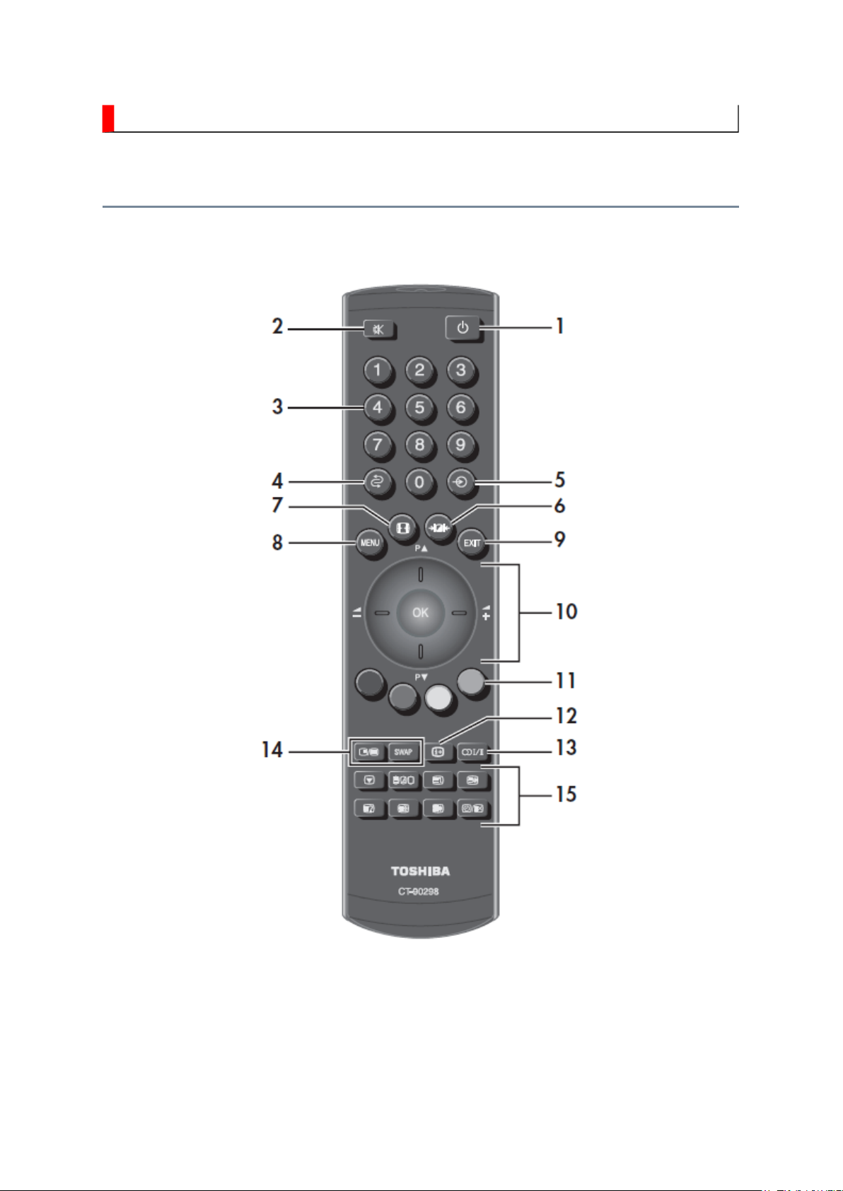
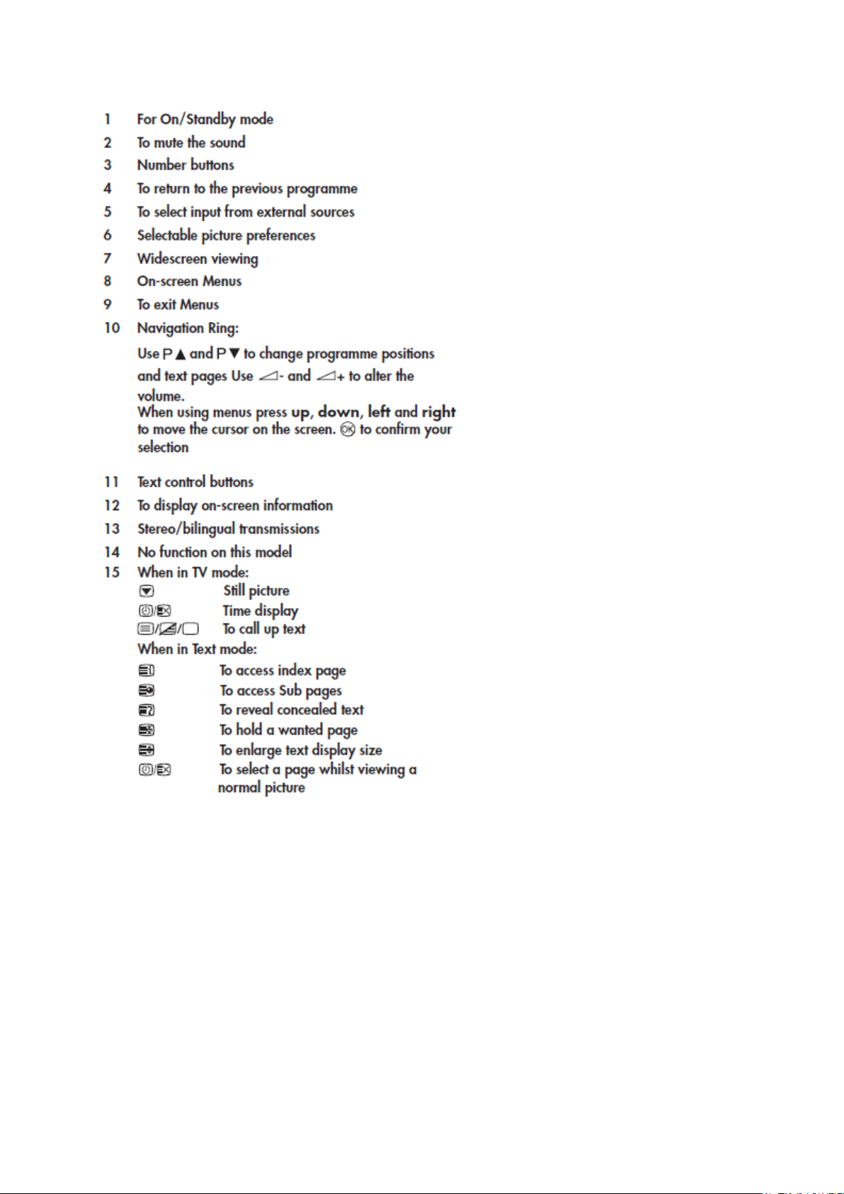
The Remote Control
Simple at-a-glance reference of your remote control.
Page 3
Стр. 2 из
2
03.05.2015
file://C:\Documents and Settings\Alexsandr\Local Settings\Temp\Rar$EXa0.911\19A
...
Page 4
FUNCTION AND OPERATION
Стр. 1 из
2
03.05.2015
file://C:\Documents and Settings\Alexsandr\Local Settings\Temp\Rar$EXa0.175\19A
...
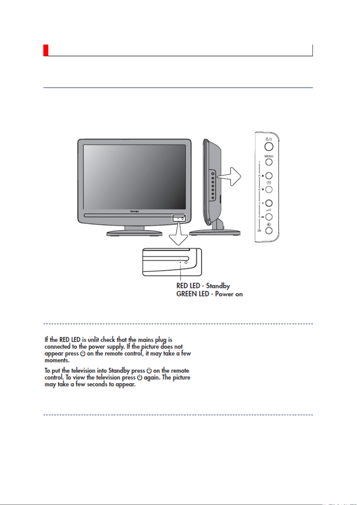
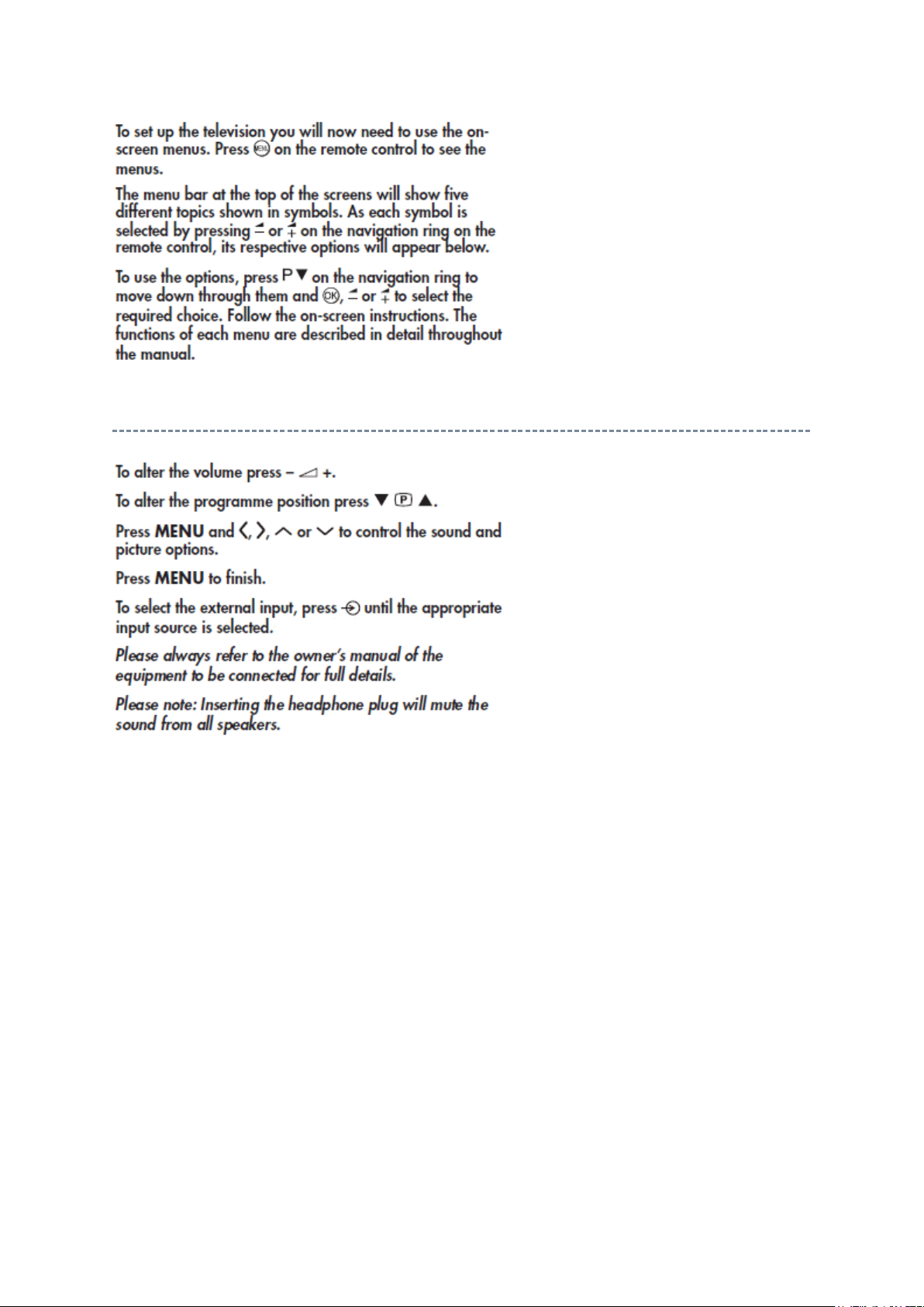
Using the Controls
Whilst all the necessary adjustments and controls for the television are made using the
remote control, the buttons on the television may be used for some functions.
Switching On
Using the Remote Control
Page 5
Using the Controls
Стр. 2 из
2
03.05.2015
file://C:\Documents and Settings\Alexsandr\Local Settings\Temp\Rar$EXa0.175\19A
...
Page 6
FUNCTION AND OPERATION
Стр. 1 из
6
03.05.2015
file://C:\Documents and Settings\Alexsandr\Local Settings\Temp\Rar$EXa0.505\19A
...
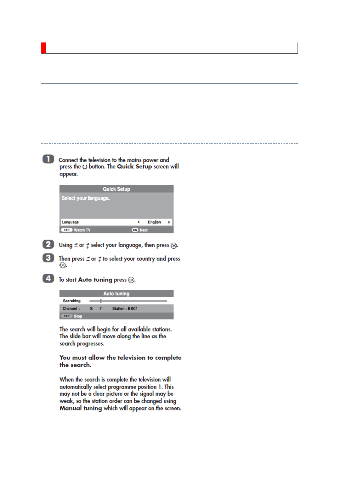
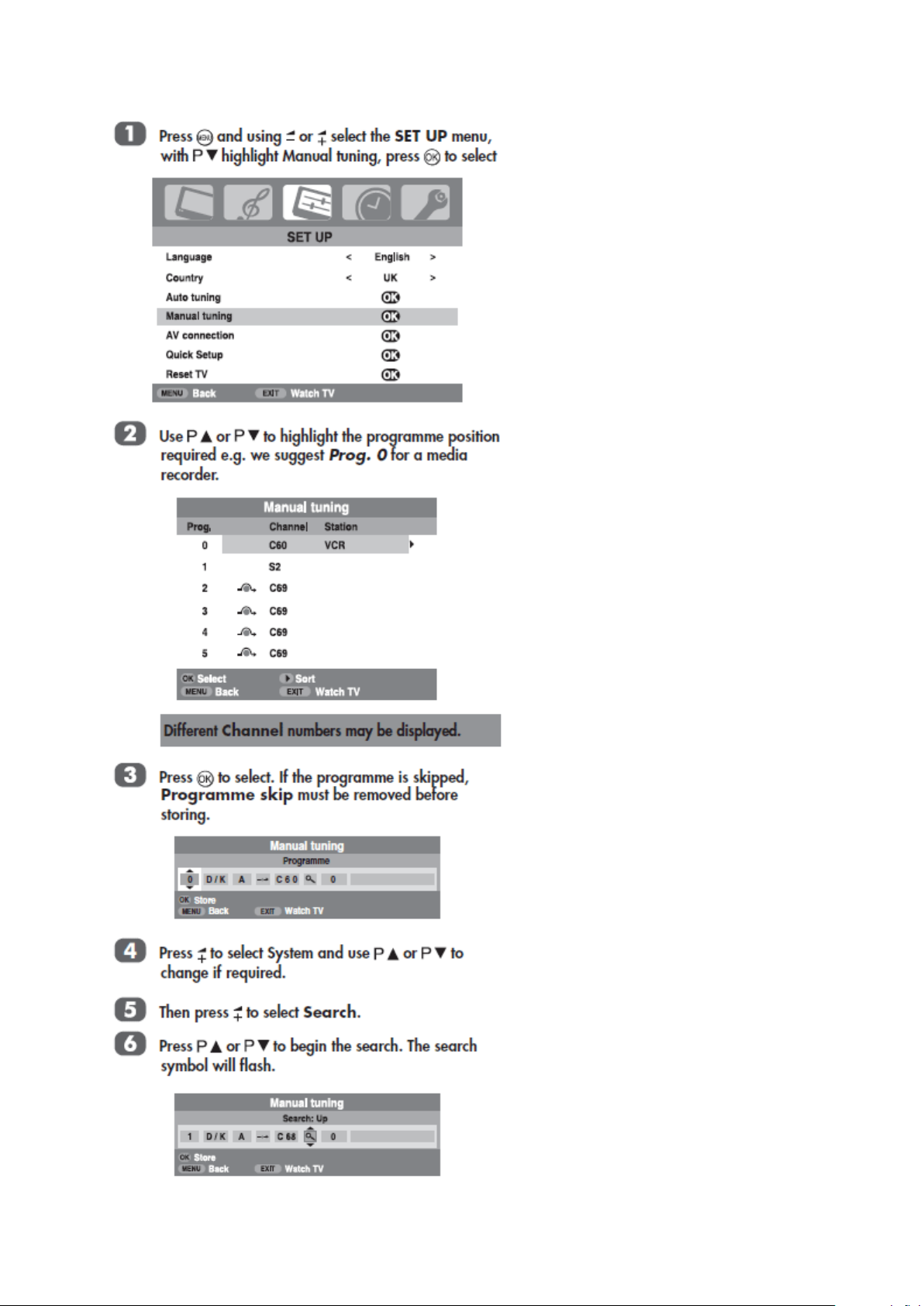
Tuning the Television
Before switching on the television put your decoder and media recorder to
are connected.
Quick Setup
Standby
if they
Page 7
Стр. 2 из
6
03.05.2015
file://C:\Documents and Settings\Alexsandr\Local Settings\Temp\Rar$EXa0.505\19A
...
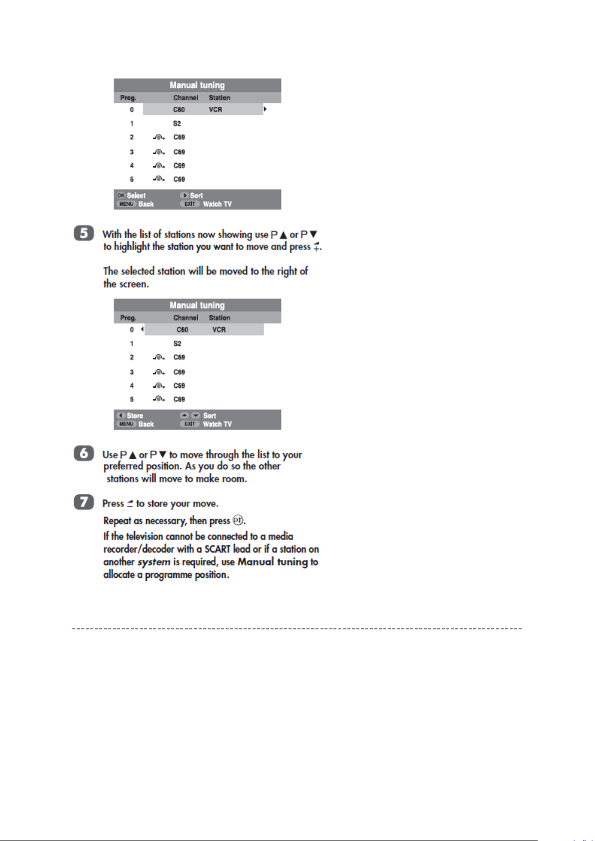
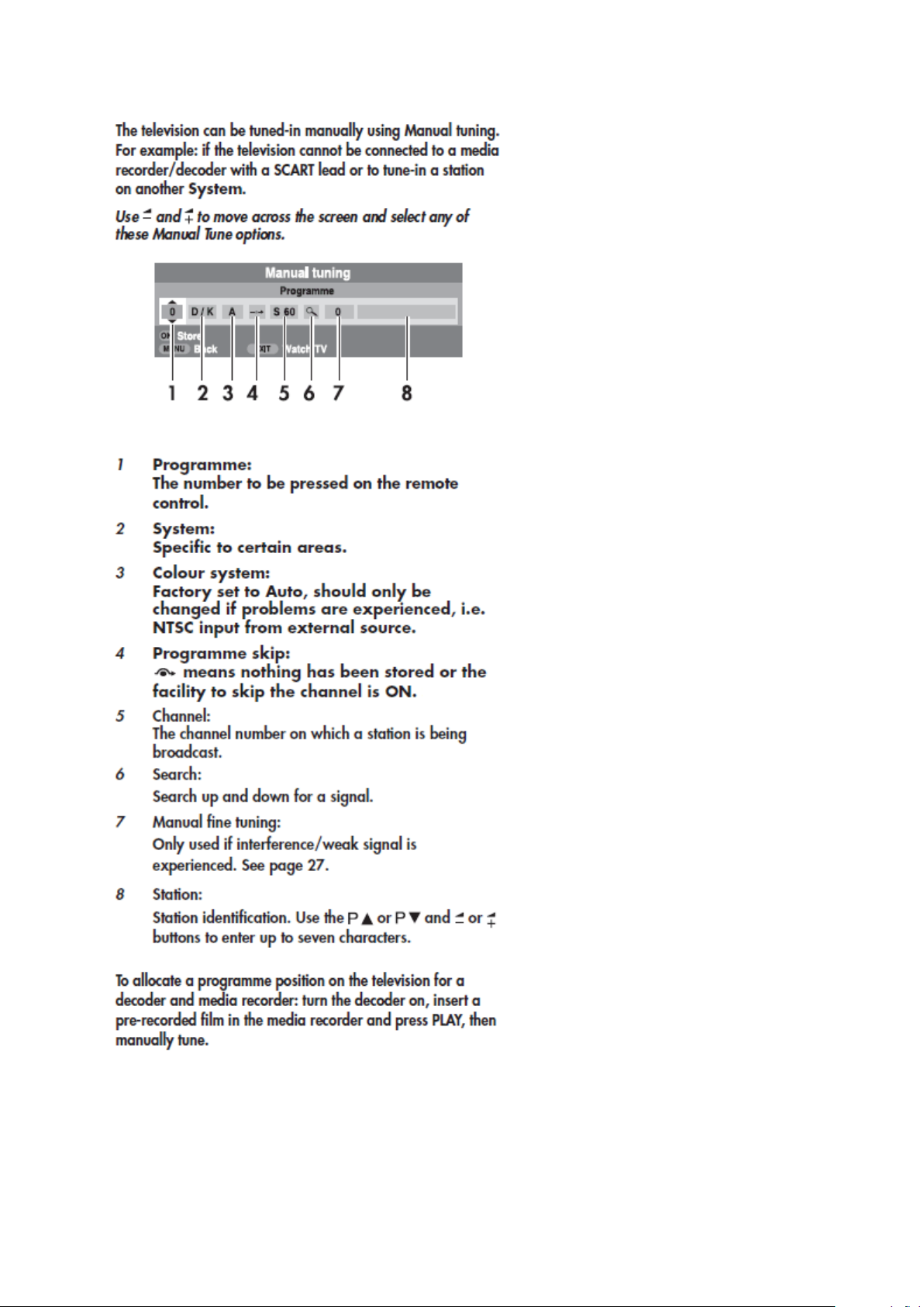
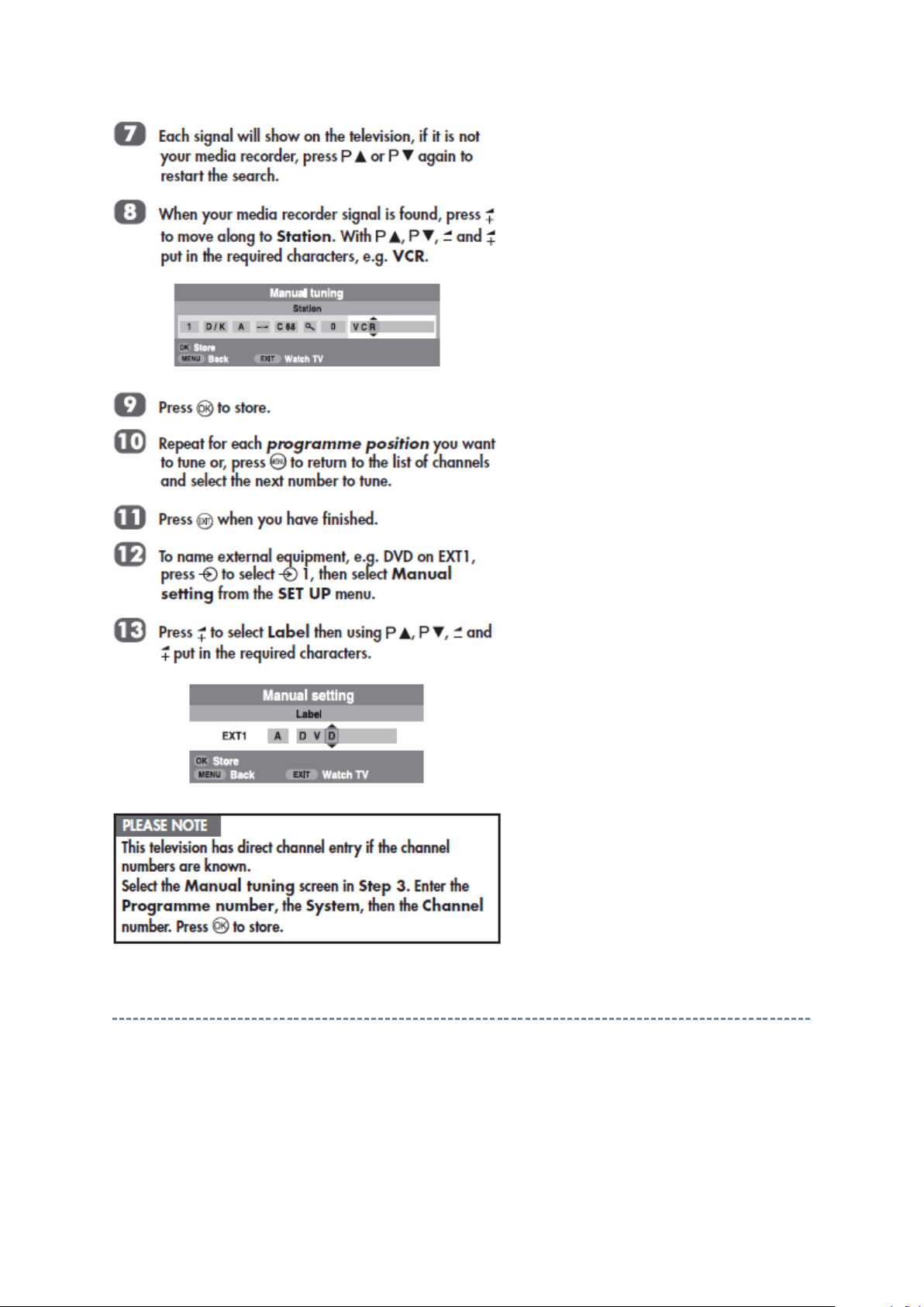
Manual Tune
Page 8
Стр. 3 из
6
03.05.2015
file://C:\Documents and Settings\Alexsandr\Local Settings\Temp\Rar$EXa0.505\19A
...
Page 9
Стр. 4 из
6
03.05.2015
file://C:\Documents and Settings\Alexsandr\Local Settings\Temp\Rar$EXa0.505\19A
...
Page 10
Стр. 5 из
6
03.05.2015
file://C:\Documents and Settings\Alexsandr\Local Settings\Temp\Rar$EXa0.505\19A
...
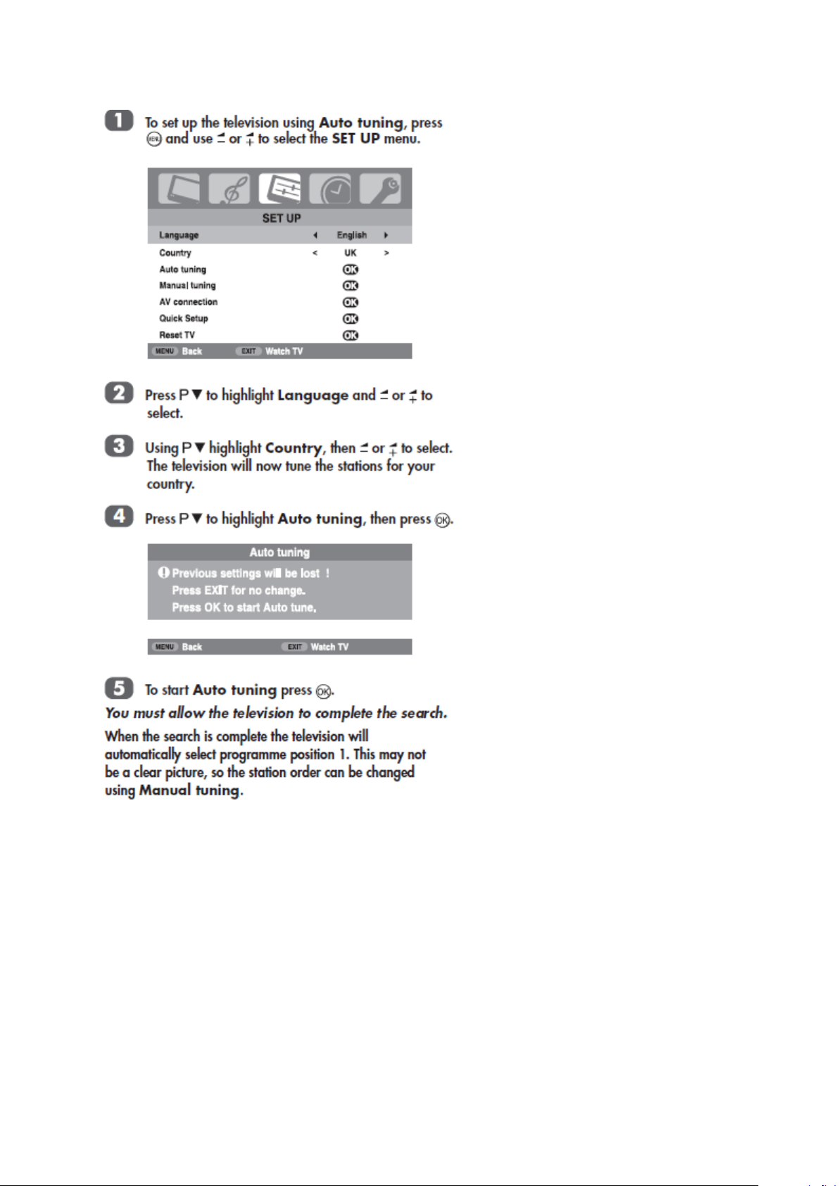
Using Auto Tuning
Page 11
Стр. 6 из
6
03.05.2015
file://C:\Documents and Settings\Alexsandr\Local Settings\Temp\Rar$EXa0.505\19A
...
Page 12

SAFETY INSTRUCTION
should enter the mouth, rinse the mouth thoroughly with water. If the fluid should contact the
When attaching the LCD module to the LCD cover, position it appropriately and fasten
Стр. 1 из 4Handling the LCD Module
03.05.2015
file://C:\Documents and Settings\Alexsandr\Local Settings\Temp\Rar$EXa0.061\19A
...
Handling the LCD Module
Safety Precaution
In the event that the screen is damaged or the liquid crystal (fluid) leaks, do not breathe in or
drink this fluid.
Also, never touch this fluid. Such actions could cause toxicity or skin irritation. If this fluid
skin or clothing, wipe off with alcohol, etc., and rinse thoroughly with water. If the fluid
should enter the eyes, immediately rinse the eyes thoroughly with running water.
Precautions for Handling the LCD Module
CAUTION: The metal edges of the LCD module are sharp, handle it with
care.
The LCD module can easily be damaged during disassembly or reassembly; therefore,
always observe the following precautions when handling the module.
1.
at the position where the display can be viewed most conveniently.
2. Carefully align the holes at all four corners of the LCD module with the corresponding
holes in the LCD cover and fasten with screws. Do not strongly push on the module
because any impact can adversely affect the performance. Also use caution when
handling the polarized screen because it can easily be damaged.
Page 13

Стр. 2 из 4Handling the LCD Module
03.05.2015
file://C:\Documents and Settings\Alexsandr\Local Settings\Temp\Rar$EXa0.061\19A
...
3. If the panel surface becomes soiled, wipe with cotton or a soft cloth. If this does not
remove the soiling, breathe on the surface and then wipe again.
If the panel surface is extremely solied, use a CRT cleaner as a cleaner. Wipe off the
panel surface by drop the cleaner on the cloth. Do not drop the cleaner on the panel.
Pay attention not to scratch the panel surface.
4. Leaving water or other fluids on the panel screen for an extended period of time can
result in discoloration or stripes. Immediately remove any type of fluid from the screen.
5. Glass is used in the panel, so do not drop or strike with hard objects. Such actions can
damage the panel.
Page 14

6. CMOS-LSI circuitry is used in the LCD module, so avoid damage due to static
Стр. 3 из 4Handling the LCD Module
03.05.2015
file://C:\Documents and Settings\Alexsandr\Local Settings\Temp\Rar$EXa0.061\19A
...
electricity. When handling the module, use a wrist ground or anchor ground.
7. Do not expose the LCD module to direct sunlight or strong ultraviolet rays for an
extended period of time.
8. Do not store the LCD module below the temperature conditions described in the
specifications. Failure to do so could result in freezing of the liquid crystal due to cold
air or loss of resilience or other damage.
9. Do not disassemble the LCD module. Such actions could result in improper operation.
Page 15

Стр. 4 из 4Handling the LCD Module
03.05.2015
file://C:\Documents and Settings\Alexsandr\Local Settings\Temp\Rar$EXa0.061\19A
...
10. When transporting the LCD module, do not use packing containing epoxy resin
(amine) or silicon resin (alcohol or oxim). The gas generated by these materials can
cause loss of polarity.
Page 16

Page 17

SAFETY INSTRUCTION
Always keep tools, components of the product, etc away from the children, These items
Стр. 1 из
4
03.05.2015
file://C:\Documents and Settings\Alexsandr\Local Settings\Temp\Rar$EXa0.976\19A
...
WARNING: BEFORE SERVICING THIS CHASSIS, READ THE "SAFETY
PRECAUTION" AND "PRODUCT SAFETY NOTICE" INSTRUCTIONS BELOW.
Safety Precaution
WARNING: SERVICING SHOULD NOT BE ATTEMPTED BY ANYONE
UNFAMILIAR WITH THE NECESSARY PRECAUTIONS ON THIS RECEIVER.
THE FOLLOWING ARE THE NECESSARY PRECAUTIONS TO BE OBSERVED
BEFORE SERVICING THIS CHASSIS.
1. An isolation transformer should be connected in the power line between the receiver
and the AC line before any service is performed on the receiver.
2. Always disconnect the power plug before any disassembling of the product. It may
result in electrical shock.
3. When replacing a chassis in the cabinet, always be certain that all the protective
devices are put back in place, such as nonmetallic control knobs, insulating covers,
shields, isolation resistor-capacitor network, etc.
4.
may cause injury to children.
5. Depending on the model, use an isolation transformer or wear suitable gloves when
servicing with the power on, and disconnect the power plug to avoid electrical shock
when replacing parts. In some cases, alternating current is also impressed in the
chassis, so electrical shock is possible if the chassis is contacted with the power on.
6. Always use the replacement parts specified for the particular model when making
repairs. The parts used in products require special safety characteristics such as
Page 18

inflammability, voltage resistance, etc. therefore, use only replacement parts that have
NEVER remodel the product in any way. Remodeling can result in improper operation,
Стр. 2 из
4
03.05.2015
file://C:\Documents and Settings\Alexsandr\Local Settings\Temp\Rar$EXa0.976\19A
...
these same characteristics. Use only the specified parts when the mark is indicated
in the circuit diagram or parts list.
7. Parts mounting and routing dressing of wirings should be the same as that used
originally. For safety purposes, insulating materials such as isolation tube or tape are
sometimes used and printed circuit boards are sometimes mounted floating. Also make
sure that wirings is routed and clamped to avoid parts that generate heat and which use
high voltage. Always follow the manufactured wiring routes / dressings.
8. Always ensure that all internal wirings are in accordance before re-assembling the
external casing after a repairing completed. Do not allow internal wiring to be pinched
by cabinets, panels, etc. Any error in reassembly or wiring can result in electrical
leakage, flame, etc., and may be hazardous.
9.
malfunction, or electrical leakage and flame, which may be hazardous.
10. Touch current check. (After completing the work, measure touch current to prevent an
electric shock.)
Plug the AC cord directly into the AC outlet. Do NOT use an isolation transformer
for this check.
Connect a measuring network for touch currents between each exposed metallic part
on the set and a good earth ground such as a water pipe.
Annex D
(normative)
Measuring network for TOUCH CURRENTS
Page 19

Resistance values in orms (Ω).
V: Voltmeter or oscilloscope
Стр. 3 из
4
03.05.2015
file://C:\Documents and Settings\Alexsandr\Local Settings\Temp\Rar$EXa0.976\19A
...
(r.m.s. or peak reading)
Input resistance : 1 MΩ
Input capacitance : 200 pF
Frequency range : 15 Hz to 1 MHz and d.c. respectively
Appropriate measures should be taken to obtain the correct value in case of non
Note:
sinusoidal waveforms.
The measuring instrument is calibrated by comparing the frequency factor of with the
solid line in figure F.2 of IEC 60990 at various frequencies. A calibration curve is
constructed showing the deviation of from the ideal curve as a function of frequency.
TOUCH CURRENT = /500 (peak value).
The potential at any point (TOUCH CURRENT) expressed as voltage and
does not exceed the following value:
The part or contact of a TERMINAL is not HAZARDOUS LIVE if:
a) The open-circuit voltage should not exceed 35 V (peak) a.c. or 60 V d.c. or, if a) is not
met.
b) The measurement of the TOUCH CURRENT shall be carried out in accordance with
IEC 60990, with the measuring network described in
The TOUCH CURRENT expressed as voltages and , does not exceed the
following values:
- for a.c. : = 35 V (peak) and = 0.35 V (peak);
- for d.c. : = 1.0 V
The limit values of = 0.35 V (peak) for a.c. and = 1.0 V for d.c. correspond to
Note:
the values 0.7 mA (peak) a.c. and 2.0 mA d.c.
Annex D
of this standard.
Page 20

Product Safety Notice
Стр. 4 из
4
03.05.2015
file://C:\Documents and Settings\Alexsandr\Local Settings\Temp\Rar$EXa0.976\19A
...
Many electrical and mechanical parts in this chassis have special safety-related
characteristics. These characteristics are often passed unnoticed by a visual inspection and
the protection afforded by them cannot necessarily be obtained by using replacement
components rated for higher voltage, wattage, etc. Replacement parts which have these
special safety characteristics are identified in this manual and its supplements; electrical
components having such features are identified by the international hazard symbols on the
schematic diagram and the parts list.
Before replacing any of these components, read the parts list in this manual carefully. The
use of substitute replacement parts which do not have the same safety characteristics as
specified in the parts list may create electrical shock, fire, or other hazards.
Page 21

!"# $%&'(#)*+,$%# -%*.-*%$
"/-'(#0&1&-2 345 !"678 !97:;
<'=$(
>'?#@A 345 ??? BBBBBB BB @A-C#0&1&-
D#0&1&-2 D#0&1&-2 E#0&1&-2 F0&1&-2 4C$=#-C$#G'=$(#H$%2&/=#&2#*G0'-$0#I&-C&=#-C$#2'+$#G'=$(#H$=0/%J# @ K%&1&='(
L
MMMMM@NOOOOOOP -C$#('2-#0&1&-#I&((#,$#&=.%$+$=-$0#,Q#@R F S$%2&/=#%$H&2$0
D S$%2&/=#%$H&2$0
$R1R @D-C#0&1&- @A-C#0&1&- A S$%2&/=#%$H&2$0
7=#.'2$#/T#:UKJ V&%2- : @ W S$%2&/=#%$H&2$0
H$2&/=#*G# F=0 : F E S$%2&/=#%$H&2$0
D%0 : D X S$%2&/=#%$H&2$0
YK><:; A-C : A Z S$%2&/=#%$H&2$0
U : @M@[DMM O S$%2&/=#%$H&2$0
YC&=' DM@[WMM 4C$=#-C$#G'=$(#&2#.C'=1$0#-/#'=/-C$%#G'=$(#H$=0/%J#-C$#'(GC',$-#G'=$(#
:2&'#L\:*2P WM@[XMM H$=0/%#&=0&.'-&/=#I&((#,$#.C'=1$0#-/#'../%0&=1(Q#I&-C#-',$(#,$(/IR
!U XM@[OMM
K-C$% OM@[OOO $R1R @D-C#0&1&- @A-C#0&1&-
K%&1&='(#:UK : @
3]3$'% Z FMMZ YC'=1$0#-/#;<; ; @
O FMMO
: FM@M
^ FM@@
Y FM@F
45]4$$_ M@ 45M@
MF 45MF
MD 45MD
MA 45MA
WD 45WD
Europe Model SET ID
19AV500PG 701
19AV500PR 702
19AV500PB 703
19AV501PG 704
19AV501PR 705
26AV500PB 706
26AV500PG 707
26AV500PR 708
19AV505DB 709
19AV505DG 710
19AV506DB 711
19AV506DG 712
26AV505DB 713
26AV505DG 714
Page 22

SPECIFICATION
Стр. 1 из
2
03.05.2015
file://C:\Documents and Settings\Alexsandr\Local Settings\Temp\Rar$EXa0.005\19A
...
Page 23

Стр. 2 из
2
03.05.2015
file://C:\Documents and Settings\Alexsandr\Local Settings\Temp\Rar$EXa0.005\19A
...
Page 24

Page 25

PARTS LIST
Electric Parts
E100
7501 1 551
H-CON SET, STV19TA MB CN6
-
SPK, 39C00I51L01
Electric Parts
E101
7501 1 552
H-CON SET, STV19TA MB CN1
-
KEY, 39C00I51L02
Electric Parts
E102
7501 1 554
PC BOARD ASSY, IR/B, 19AV500U, 39C00I51L04
Electric Parts
E103
7501 1 555
PC BOARD ASSY, KEY/B, 19AV500U, 39C00I51L05
Electric Parts
E104
7501 1 558
H-CON SET, STV19T POW
-
IF 12P, 39C00I51L08
Electric Parts
E109
7501 2 363
PC BOAD ASSY, POWER, 39C00S51L17
Electric Parts
E110
7501 2 364
PC BOARD ASSY, MAIN ,19AV500P, 39C00S51L04
Electric Parts
E114
7501 2 368
H-CON SET, 39C00L51L06
Electric Parts
E115
7501 2 369
POWER CORD, 39C00S51L16
Miscellaneous
E106
7501 1 562
SPEAKER ASSY, 3W 6OHM 60X35.5X26, 39C00I51L16
Miscellaneous
E111
7501 1 549
LCD PANEL, LTM190 M2
-
L31REV.40D, 39C00I51LP1
Miscellaneous
E119
7501 2 373
SHEET FOR CLEAN CLOTH, 39C00S51L11
Miscellaneous
E120
7501 2 376
WARRANTY CARD, 39C00S51L12
Accessory
E117
7501 2 371
OWNERS MANUAL, 19AV500PG, 39C00S51L14
Accessory
E117
7501 2 375
OWNERS MANUAL, 19AV500PR, 39C00S51L13
Accessory
E118
7501 2 372
INSTRUCTION, 19AV500P, 39C00S51L01
Accessory
E121
7501 2 374
REMOCON HAND UNIT, 39C00S51L05
Cabinet
E105
7501 1 560
STAND ASSY, 19AV500U, 39C00I51L10
Cabinet
E112
7501 2 366
COVER ASSY, BACK, 19AV500P
Cabinet
E113
7501 2 367
BEZEL ASSY, 19AV500P, 39C00S51L03
Packing
E021
7501 2 463
HANDLE, CARTON BOX 19V, 39C00J51L24
Packing
E107
7501 1 564
EPS FOAM, LEFT, 19AV500U, 39C00J51L01
Packing
E108
7501 1 565
EPS FOAM, RIGHT, 19AV500U, 39C00J51L02
Packing
E116
7501 2 370
CARTON BOX, 19AV500P, 39C00T51L02
Стр. 1 из
1
03.05.2015
file://C:\Documents and Settings\Alexsandr\Local Settings\Temp\Rar$EXa0.323\19A
...
Block :
All Block
Location :
Parts No. :
Block Location Parts No. Description
Search
Search
Page :
1 /
24
Jump
S MM L
Page 26

PARTS LIST
Electric Parts
E100
7501 1 551
H-CON SET, STV19TA MB CN6
-
SPK, 39C00I51L01
Electric Parts
E101
7501 1 552
H-CON SET, STV19TA MB CN1
-
KEY, 39C00I51L02
Electric Parts
E102
7501 1 554
PC BOARD ASSY, IR/B, 19AV500U, 39C00I51L04
Electric Parts
E103
7501 1 555
PC BOARD ASSY, KEY/B, 19AV500U, 39C00I51L05
Electric Parts
E104
7501 1 558
H-CON SET, STV19T POW
-
IF 12P, 39C00I51L08
Electric Parts
E109
7501 2 363
PC BOAD ASSY, POWER, 39C00S51L17
Electric Parts
E110
7501 2 364
PC BOARD ASSY, MAIN ,19AV500P, 39C00S51L04
Electric Parts
E114
7501 2 368
H-CON SET, 39C00L51L06
Electric Parts
E115
7501 2 369
POWER CORD, 39C00S51L16
Стр. 1 из
1
03.05.2015
file://C:\Documents and Settings\Alexsandr\Local Settings\Temp\Rar$EXa0.323\19A
...
Block :
Electric Parts
Location :
Parts No. :
Block Location Parts No. Description
Search
Search
Page :
1 /
9
S MM L
Jump
Page 27

PARTS LIST
Miscellaneous
E106
7501 1 562
SPEAKER ASSY, 3W 6OHM 60X35.5X26, 39C00I51L16
Miscellaneous
E111
7501 1 549
LCD PANEL, LTM190 M2
-
L31REV.40D, 39C00I51LP1
Miscellaneous
E119
7501 2 373
SHEET FOR CLEAN CLOTH, 39C00S51L11
Miscellaneous
E120
7501 2 376
WARRANTY CARD, 39C00S51L12
Стр. 1 из
1
03.05.2015
file://C:\Documents and Settings\Alexsandr\Local Settings\Temp\Rar$EXa0.323\19A
...
Block :
Miscellaneous
Location :
Parts No. :
Block Location Parts No. Description
Search
Search
Page :
1 /
4
Jump
S MM L
Page 28

PARTS LIST
Accessory
E117
7501 2 371
OWNERS MANUAL, 19AV500PG, 39C00S51L14
Accessory
E117
7501 2 375
OWNERS MANUAL, 19AV500PR, 39C00S51L13
Accessory
E118
7501 2 372
INSTRUCTION, 19AV500P, 39C00S51L01
Accessory
E121
7501 2 374
REMOCON HAND UNIT, 39C00S51L05
Стр. 1 из
1
03.05.2015
file://C:\Documents and Settings\Alexsandr\Local Settings\Temp\Rar$EXa0.323\19A
...
Block :
Accessory
Location :
Parts No. :
Block Location Parts No. Description
Search
Search
Page :
1 /
4
S MM L
Jump
Page 29

PARTS LIST
Cabinet
E105
7501 1 560
STAND ASSY, 19AV500U, 39C00I51L10
Cabinet
E112
7501 2 366
COVER ASSY, BACK, 19AV500P
Cabinet
E113
7501 2 367
BEZEL ASSY, 19AV500P, 39C00S51L03
Стр. 1 из
1
03.05.2015
file://C:\Documents and Settings\Alexsandr\Local Settings\Temp\Rar$EXa0.323\19A
...
Block :
Cabinet
Location :
Parts No. :
Block Location Parts No. Description
Search
Search
Page :
S MM L
1 /
3
Jump
Page 30

PARTS LIST
Packing
E021
7501 2 463
HANDLE, CARTON BOX 19V, 39C00J51L24
Packing
E107
7501 1 564
EPS FOAM, LEFT, 19AV500U, 39C00J51L01
Packing
E108
7501 1 565
EPS FOAM, RIGHT, 19AV500U, 39C00J51L02
Packing
E116
7501 2 370
CARTON BOX, 19AV500P, 39C00T51L02
Стр. 1 из
1
03.05.2015
file://C:\Documents and Settings\Alexsandr\Local Settings\Temp\Rar$EXa0.323\19A
...
Block :
Packing
Location :
Parts No. :
Block Location Parts No. Description
Search
Search
Page :
1 /
S MM L
4
Jump
Page 31

PARTS LIST
Стр. 1 из
2
03.05.2015
file://C:\Documents and Settings\Alexsandr\Local Settings\Temp\Rar$EXa0.415\19A
...
Precaution
WARNING: BEFORE SERVICING THIS CHASSIS, READ THE "X-RAY
RADIATION PRECAUTION" FOR DIRECT VIEW CTV ONLY, "SAFETY
PRECAUTION" AND "PRODUCT SAFETY NOTICE" OF THIS MANUAL.
CAUTION: The international hazard symbols " " in the schematic diagram
and the parts list designate components which have special characteristics
important for safety and should be replaced only with types identical to
those in the original circuit or specified in the parts list.
The mounting position of replacements is to be identical with originals.
Before replacing any of these components, read carefully the SAFETY
PRECAUTION and PRODUCT SAFETY NOTICE.
Do not degrade the safety of the receiver through improper servicing.
Note:
The part number must be used when ordering parts, in order to assist in processing, be
sure to include the Model number and Description.
The PC board assembly with mark is no longer available after the end of the
production.
Abbreviations
Capacitors CD : Ceramic Disk
Resistors CF : Carbon film
OMF : Oxide Metal Film
PF : Plastic Film
CC : Carbon Composition
VR : Variable Resistor
EL : Electrolytic
Page 32

MF : Metal Film
Стр. 2 из
2
03.05.2015
file://C:\Documents and Settings\Alexsandr\Local Settings\Temp\Rar$EXa0.415\19A
...
FR : Fusible Resistor
All CD and PF capacitors are ±5 %, 50 V and all resistor, ±5 %, 1/6 W unless otherwise
noted.
Page 33

Page 34

Page 35

KeypadMainBoard
PowerboardPanelmodule
Speaker
Keypad-7P
1
PWR_KEY
MENU
2
CH+
3
CH-
4
VOL+
5
6
VOL-
INPUT/EXIT
7
GND
8
IR board
IR boa rd -6 P
5V_STANDB Y
1
LED-G 15
2
3
LED-R 16
LED-C 17
4
IR_DATA 18
5
GND 19
6
L Speaker
1
LCH+ 25
LCH-
2
R Speaker
RCH-
1
RCH+
2
1
PWR_KEY 1
MENU 2
2
CH+ 3
3
CH- 4
4
VOL+ 5
5
6
VOL- 6
INPUT/EXIT 7
7
GND 8
8
LED-G 9
9
LED-R 10
10
11
LED-C 11
GND 12
12
13
IR_DATA 13
5V_STANDB Y 14
14
Speaker -4P
LCH+ 26
1
2
LCH- 27
RCH- 28
3
RCH+ 29
4
LVDS -2x15PKEY/IR -14P
RXE3+
Vcc:+5V
RXE3-
Vcc:+5V
RXECLK +
Vcc:+5V
RXECLK -
GND
RXE2+
GND
RXE2-
GND
RXE1+
GND
RXE1-
NC
RXE0+
NC
20
21
22
23
24
30
RXE0-
RXO0-
NC
RXO0+
RXO3+
RXO1-
RXO3-
RXO1+
RXOCLK+
RXO2-
RXOCLK-
RXO2+
Power supply - 12P 5
1 5V_IN 1 5V_IN 6
2 5V_IN 2 5V_IN 7
3 GND 3 GND_P 8
4 GND 4 GND_P 9
5 PO WER_EN 5 #POWER_EN 10
6 BK LT_ON_POwER 6 #IINVERTER 11
7 BK LT_ADJ_PO wER 7 #BRIGHT 12
8 12V CCIN 8 12VCCIN 13
9 12V CCIN 9 12VCCIN 14
10 GND 10 GND_A 15
11 GND 11 GND_A 1 Hot-1 16
12 AC_LIN E_DETE CTION 12 #ACD Upper 2 C old-1 17
Power:JWT/A2008WV0-12P-6T
Back Light Unit
3 Hot-2 18
4 Cold-2 19
1 Hot-1 20
J901,J902,J903,J904 Low er 2 Cold-1 21
CCFL
1 HV 4 Cold-2 23
2 LV 24
AC In
1 Line 28
2 NC 29
3 Line 30
3 Hot-2 22
19” Sa msung panel LT M190M2-L31
UJU connector IS100-L30O-C23
1
2
3
4
25
26
27
RXO0-
RXO0+
RXO1-
RXO1+
RXO2-
RXO2+
GND
RXOCRXOC+
RXO3-
RXO3+
RXE0-
RXE0+
GND
RXE1-
RXE1+
GND
RXE2-
RXE2+
RXEC-
RXEC+
RXE3-
RXE3+
GND
NC
NC
NC
VDD:+5V
VDD:+5V
VDD:+5V
 Loading...