

Page 1
FormNo.3386-335RevA
RT600TractionUnit
ModelNo.25430A—SerialNo.315000001andUp
ModelNo.25430C—SerialNo.315000001andUp
ModelNo.25430W—SerialNo.315000001andUp
Registeratwww.T oro.com.
OriginalInstructions(EN)
*3386-335*A
Page 2
WARNING
CALIFORNIA
Proposition65Warning
Thisproductcontainsachemicalorchemicals
knowntotheStateofCaliforniatocausecancer,
birthdefects,orreproductiveharm.
Theengineexhaustfromthisproduct
containschemicalsknowntotheStateof
Californiatocausecancer,birthdefects,
orotherreproductiveharm.
Becauseinsomeareastherearelocal,state,orfederal
regulationsrequiringthatasparkarresterbeusedonthe
engineofthismachine,asparkarresterisavailableas
anoption.Ifyourequireasparkarrester,contactyour
AuthorizedToroServiceDealer.
Figure1
Important:ItisaviolationofCaliforniaPublic
ResourceCodeSection4442touseoroperatetheengine
onanyforest-covered,brush-covered,orgrass-covered
landwithoutasparkarrestermufermaintainedin
workingorder,ortheengineconstricted,equipped,and
maintainedforthepreventionofre.Otherstatesor
federalareasmayhavesimilarlaws.
GenuineT orosparkarrestersareapprovedbytheUSDA
ForestryService.
TheenclosedEngineOwner’sManualissuppliedfor
informationregardingtheUSEnvironmentalProtection
Agency(EPA)andtheCaliforniaEmissionControl
Regulationofemissionsystems,maintenance,and
warranty.Replacementsmaybeorderedthroughthe
enginemanufacturer.
Introduction
Thismachineisdesignedtodigtrenchesinsoiltobury
cablingandpipingforvariousapplications.Itisnotintended
tocutrock,wood,oranyothermaterialotherthansoil.
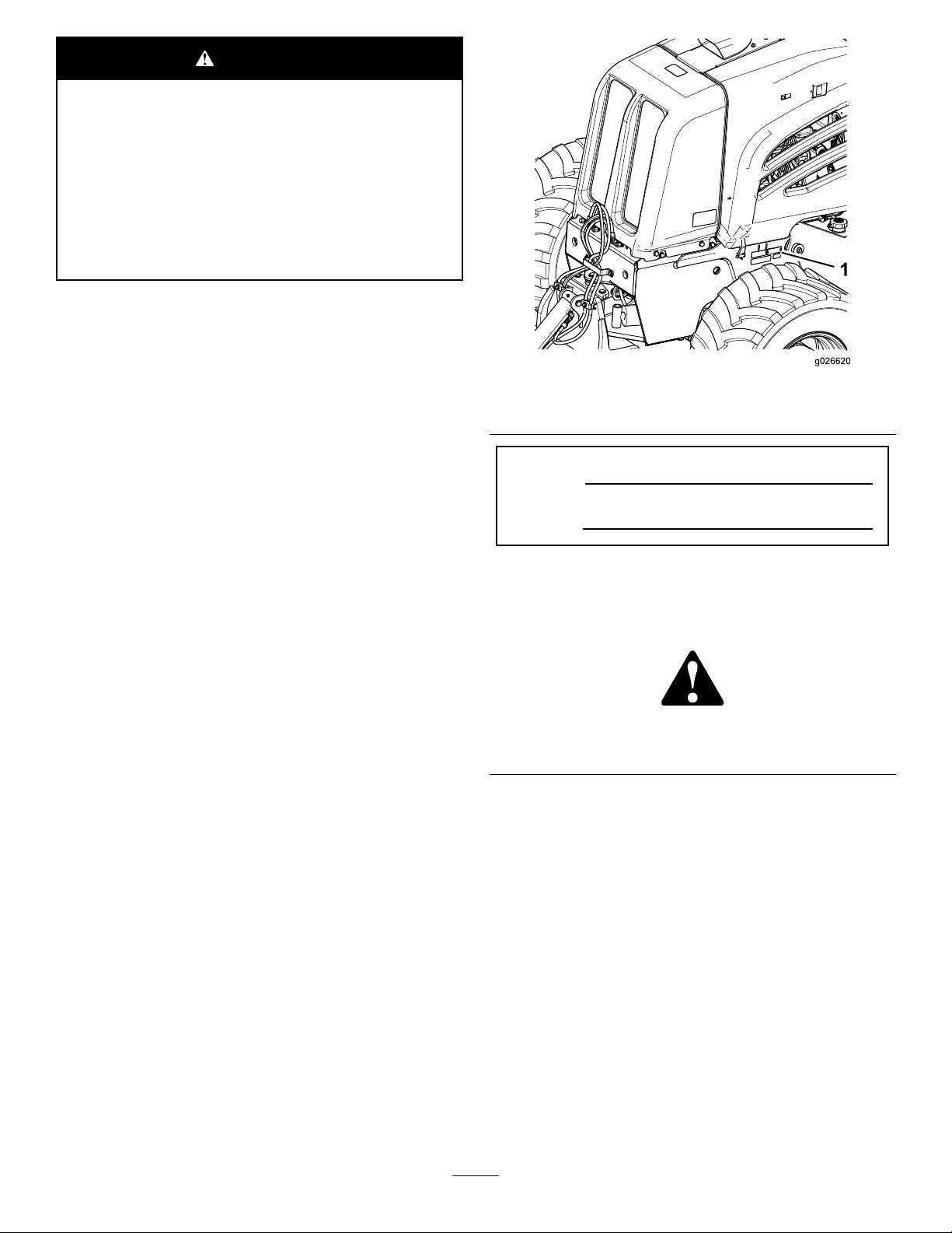
1.Locationofthemodelandserialnumberplate
ModelNo.
SerialNo.
Thismanualidentiespotentialhazardsandhassafety
messagesidentiedbythesafetyalertsymbol(Figure2),
whichsignalsahazardthatmaycauseseriousinjuryordeath
ifyoudonotfollowtherecommendedprecautions.
Figure2
1.Safetyalertsymbol
Thismanualuses2wordstohighlightinformation.
Importantcallsattentiontospecialmechanicalinformation
andNoteemphasizesgeneralinformationworthyofspecial
attention.
Readthisinformationcarefullytolearnhowtooperateand
maintainyourproductproperlyandtoavoidinjuryand
productdamage.Youareresponsibleforoperatingthe
productproperlyandsafely.
YoumaycontactT orodirectlyatwww .Toro.comforproduct
andaccessoryinformation,helpndingadealer,ortoregister
yourproduct.
Wheneveryouneedservice,genuineT oroparts,oradditional
information,contactanAuthorizedToroServiceDealer
orToroCustomerServiceandhavethemodelandserial
numbersofyourproductready.Figure1illustratesthe
locationofthemodelandserialnumbersontheproduct.
Writethenumbersinthespaceprovided.
©2014—TheToro®Company
8111LyndaleAvenueSouth
Bloomington,MN55420
Contents
Safety...........................................................................3
............................................................................4
ElectricalLineSafety...............................................6
GasLineSafety.......................................................6
CommunicationLineSafety......................................6
WaterLineSafety....................................................6
SafetyandInstructionalDecals.................................7
ProductOverview.........................................................14
Controls...............................................................15
InstrumentCluster..............................................15
Contactusatwww.Toro.com.
2
PrintedintheUSA
AllRightsReserved
Page 3

TractionControls...............................................18
AttachmentControlPanel....................................19
OperatorSeatandSeatBelt.................................20
Specications........................................................21
Attachments/Accessories........................................21
Operation....................................................................22
PreparingforWork.................................................22
AddingFueltotheEngine.......................................22
CheckingtheEngineOilLevel.................................23
CheckingtheHydraulicFluidLevel...........................24
InspectingtheMachineDaily...................................25
StartingtheEngine.................................................25
SettingtheEngineSpeed.........................................25
StoppingtheEngine...............................................26
BreakinginaNeworRebuiltEngine.........................26
OperatingtheMachineinExtreme
Conditions.........................................................26
OperatingtheParkingBrake....................................27
DrivingandStoppingtheMachine............................27
OperatingtheTransmission.....................................28
PreparingtoOperatetheMachine.............................29
UsingtheBackllBlade...........................................29
TransportingtheMachine........................................30
CompletingtheWorkfortheDay.............................31
CompletingtheProject...........................................31
Maintenance.................................................................32
RecommendedMaintenanceSchedule(s)......................32
PremaintenanceProcedures........................................33
GeneralSafety........................................................33
Lubrication...............................................................33
GreasingtheMachine.............................................33
EngineMaintenance..................................................35
AccessingtheEngine..............................................35
ServicingtheEngineOilandFilter............................37
ServicingtheAir-cleanerSystem...............................39
FuelSystemMaintenance...........................................42
ServicingtheFuelSystem........................................42
ElectricalSystemMaintenance....................................45
MaintainingtheBattery...........................................45
DriveSystemMaintenance.........................................48
ServicingtheTires..................................................48
ServicingtheAxlesandtheTransmission...................49
CoolingSystemMaintenance......................................54
ServicingtheCoolingSystem...................................54
BeltMaintenance......................................................58
ServicingtheEngineDriveBelt................................58
ReplacingtheEngineDriveBelt...............................59
HydraulicSystemMaintenance....................................61
ServicingtheHydraulicSystem.................................61
ROPSMaintenance....................................................64
CheckingandServicingtheROPS.............................64
Cleaning...................................................................65
RemovingDirtandDebrisfromtheMachine.............65
Storage........................................................................66
PreparingforSeasonalStorage.................................66
Troubleshooting...........................................................67
Safety
Improperlyusingormaintainingthismachinecan
resultininjury.T oreducethepotentialforinjury,comply
withthesesafetyinstructionsandalwayspayattentionto
thesafetyalertsymbol(Figure2),whichmeansCaution,
Warning,orDanger—personalsafetyinstruction.Failure
tocomplywiththeinstructionmayresultinpersonal
injuryordeath.
Important:Thismachinewasmanufacturedaccording
totheappropriateregulatorystandardsineffectatthe
timeofmanufacture.Modifyingthismachineinany
waymaycauseittobeoutofcompliancewiththose
standardsandwiththeinstructionsinthis
Man ual.
onlybyanAuthorizedT oroServiceDealer.
Modicationstothismachineshouldbemade
WARNING
Welding,cutting,ordrillingcastductileironparts
ofthemachinecouldcausethemtobreakduring
operation,whichinturncouldresultininjuryor
death.
Donotweld,cut,ordrilltorepairortoattachitems
tocastductileironpartsonthismachine.
Alwaysfollowallsafetyinstructionstoavoidseriousinjury
ordeath.
Youcanpreventandareresponsibleforinjuriesoccurringto
yourselfandtoothersandfordamagetoproperty.
Donotusethismachineforapplicationsotherthanthose
whicharedescribedinthismanual.
Beforeoperatingthismachineforthepurposeoftrenching,
drilling,orotherconstructionwork,itisyourresponsibility
toknowwhereallutilitylinesareburiedintheprojectarea
andtoavoidthem.
Alwaysensurethatalllocalutilitycompaniesmark
thelocationoftheirlines.IntheUSAandCanada,
calla“One-callSystemDirectory”service.Inthe
USA,call811oryourlocalnumber.Ifyoudonotknow
yourlocalnumber,callthenationalnumber(USAand
Canadaonly)at1-888-258-0808.Also,contactanyutility
companiesthatarenotparticipantsofthe“One-call
SystemDirectory”service.
Checkwithlocalauthoritiesforalllawsandregulationsthat
requireyoutolocateandavoidexistingutilities.
Refertothefollowingtablefortheproperutilitylineandthe
correspondingutilitylinecolor(USAandCanadaonly):
Operator’ s
3
Page 4

UtilityLine
ElectricRed
Telecommunication,alarmorsignal,cables,
orconduit
Naturalgas,oil,steam,petroleum,orother
gaseousorammablematerial
SeweranddrainGreen
DrinkingwaterBlue
Reclaimedwater,irrigation,andslurrylinesPurple
TemporarysurveymarkingsPink
ProposedexcavationlimitsWhite
Afterlocatingalltheutilitylines,carefullydigaholetothe
utilitylinetoverifythelocationandthedepthoftheline.
Color
Orange
Yellow
Training
•ReadtheOperator'sManualandothertrainingmaterial.If
theoperator(s)ormechanic(s)cannotreadEnglish,itis
theowner'sresponsibilitytoexplainthismaterialtothem.
•Becomefamiliarwiththesafeoperationoftheequipment,
operatorcontrols,andsafetysigns.
•Alloperatorsandmechanicsshouldbetrained.The
ownerisresponsiblefortrainingtheusers.
•Neverletchildrenoruntrainedpeopleoperateorservice
theequipment.Localregulationsmayrestricttheageof
theoperator.
•Ensurethatyouunderstandthehandsignalsusedonthe
jobsite.Followtheinstructionsofthesignalperson.
•Beforeoperatingthemachinewithanattachment,ensure
thattheattachmentisproperlyinstalled.
•Useextracarewhenhandlingfuels.Theyareammable
andvaporsareexplosive.
–Useonlyanapprovedcontainer.
–Donotremovethefuelcaporaddfuelwiththe
enginerunning.Allowtheenginetocoolbefore
fueling.Donotsmokenearthemachinewhilethe
engineisrunning.
–Donotrefuelordrainthemachineindoors.
•Checkthattheoperator'spresencecontrols,safety
switches,andshieldsareattachedandfunctioning
properly.Donotoperatethemachineunlessthese
controls,switches,andshieldsarefunctioningproperly.
GeneralOperation
•Alwayswearaseatbeltwhenoperatingamachinewith
aROPS.
•Donotrunanengineinanenclosedarea.
•Donotoperatethemachinewithouttheguardssecurely
inplace.Ensurethatallinterlocksareattached,adjusted
properly,andfunctioningproperty.
•Decreasethegroundspeedofthemachineanduse
cautionwhenmakingturnsandcrossingroadsand
sidewalks.
•Donotoperatethemachinewhileundertheinuence
ofalcoholordrugs.
•Ensurethattheareaisclearofotherpeoplebefore
operatingthemachine.Stopthemachineifanyoneenters
thearea.
Preparation
•Beforeusingthemachine,havetheareamarkedfor
undergroundutilities,anddonotdiginmarkedareas.
Also,beawareofthelocationofobjectsandstructures
thatmaynotbemarked,suchasundergroundstorage
tanks,wells,andsepticsystems.
•Evaluatetheterraintodeterminewhataccessoriesand
attachmentsareneededtoproperlyandsafelyperform
thejob.Useonlyaccessoriesandattachmentsapproved
bythemanufacturer.
•Markthejobsiteclearlyandkeepbystandersaway.
•Reviewthejobsitehazards,safetyandemergency
procedures,andpersonnelresponsibilitieswithall
workersbeforebeginningthework.
•Wearappropriateclothing,includinghardhat,safety
glasses,longpants,safetyshoes,andhearingprotection;
somejobsmayalsorequirethatyouwearareectivevest
and/orarespirator.Securelonghair,looseclothing,and
jewelrytopreventthemfromgettingtangledinmoving
parts.
•Excessivevibrationfromatrencheroraplowcancausea
trench,anoverhang,orahighbanktocollapse,resulting
inpossibleinjuryordeath.
•Ifyourviewoftheworkareaisnotclear,alwayshavea
signalpersondirectthemovementofthemachine.
•Donotleavearunningmachineunattended.Stopthe
engineandremovethekeywheneveryouleavethe
machine.
•UseonlyToro-approvedattachments.Attachmentscan
changethestabilityandtheoperatingcharacteristicsof
themachine.
•Watchfortrafcwhenoperatingthemachinenearor
acrossroadways.
•Ensurethatyouoperatethemachineinareaswherethere
arenoobstaclesincloseproximitytoyou.Failureto
maintainanadequatedistancefromtrees,walls,andother
barrierswhileoperatingthemachinemayresultininjury
and/ordamage.Operatethemachineonlyinareaswhere
thereissufcientclearanceforyoutosafelymaneuver
theproduct.
4
Page 5

•Locatethepinchpointareasmarkedonthemachineand
attachments,andkeephandsandfeetawayfromthese
areas.
•Lightningcancausesevereinjuryordeath.Iflightning
isseenorthunderisheardinthearea,donotoperate
themachine;seekshelter.
SlopeOperation
Slopesareamajorfactorrelatedtoloss-of-controland
tip-overaccidents,whichcanresultinsevereinjuryordeath.
Allslopesrequireextracaution.
•Avoidoperatingthismachineonslopes,ifpossible.
•Keepallmovementsonslopesslowandgradual.Donot
makesuddenchangesinspeedordirection.
•Avoidstartingorstoppingthemachineonaslope.Ifthe
machinelosestraction,keeptheheavyendofthemachine
uphillandproceedslowly,straightdowntheslope.
•Avoidturningthemachineonslopes.Ifyoumustturn,
turnslowlyandkeeptheheavyendofthemachineuphill.
•Donotoperatethemachineneardrop-offs,ditches,or
embankments.Themachinecouldsuddenlyturnoverif
atiregoesovertheedgeofaclifforditch,orifanedge
cavesin.
RolloverProtectionStructure(ROPS)
System
•BeforeoperatingamachinewithaROPS(rollover
protectionstructure),ensurethattheseatbeltisingood
conditionandissecurelyattachedtothemachine.
•InspecttheROPSattheintervalrecommendedinthis
manualorwhentheROPShasbeeninanaccident.
•RepairadamagedROPSusingonlygenuineT oro
replacementparts;donotrepairormodifytheROPS.
•Checkcarefullyforoverheadclearances(i.e.branches,
doorways,electricalwires)beforedrivingunderany
objectsanddonotcontactthem.
•DonotremovetheROPSexceptwhenservicingor
replacingit.
•Donotaddweighttothemachinethatexceedsthegross
weightdisplayedontheROPSlabel.
TransportingSafety
Whenyoutransportthemachinetoorfromthejobsite,
observethefollowingsafetyprecautions:
•Donotcarrypassengersonthemachine.
•Keepallbystandersawaywhileyouaremovingthe
machine.
•Usecarewhenloadingorunloadingthemachineintoa
trailerortruck.
•Watchfortrafcwhenyouarecrossingroadwayswith
themachine.
•Checkforoverheadclearances(i.e.,branches,doorways,
electricalwires)beforedrivingunderanyobjects,anddo
notcontactthem.
•Moveallattachmentsintothetransportposition.
MaintenanceandStorage
•Lowertheattachment(s),stoptheengine,waitforall
movingpartstostop,andremovethekeywheneveryou
adjust,clean,orrepairthemachine.
•Donottouchpartsthatmaybehotfromoperation.
Allowthemtocoolbeforeattemptingtomaintain,adjust,
orservicethemachine.
•Cleandebrisfromattachments,drives,mufers,and
enginetohelppreventres.Cleanupoilandfuelspills.
•Lettheenginecoolbeforestoring,anddonotstorethe
machinenearanopename.
•Parkthemachineonlevelground.
•Donotallowuntrainedpersonneltoservicethemachine.
•Usejackstandstosupportcomponentswhenrequired.
•Carefullyreleasepressurefromcomponentswithstored
energy.
•Keephandsandfeetawayfrommovingparts.Ifpossible,
donotmakeadjustmentswiththeenginerunning.
•Keepallpartsingoodworkingconditionandallhardware
tightened.Replaceallwornordamageddecals.
•Keepnutsandboltstight.Keepallequipmentingood
condition.
•Donottamperwithsafetydevices.
•Keepthemachinecleanandfreeofdebris.
•Cleanupoilorfuelspills.
•Useextracarewhenhandlingfuels.Theyareammable
andvaporsareexplosive.
–Useonlyanapprovedcontainer.
–Donotremovethefuelcaporaddfuelwhenthe
engineisrunning.Allowtheenginetocoolbefore
refueling.Donotsmoke.
–Donotrefuelthemachineindoors.
–Donotdrainthefuelindoors.
–Donotstorethemachineorafuelcontainerinside
wherethereisanopename,suchasnearawater
heaterorfurnace.
–Donotllacontainerwhileitisinsideavehicle,
trunk,pickupbed,oranysurfaceotherthanthe
ground.
–Keepcontainernozzleincontactwiththetankduring
lling.
•UseonlygenuineTororeplacementparts.
•Disconnectthebatterybeforemakinganyrepairs.
Disconnectfromthenegativebatteryterminalrstand
5
Page 6

fromthepositivelast.Connecttothepositiverstandto
thenegativelast.
•Chargethebatteryinanopenwellventilatedarea,away
fromsparkandames.Unplugthechargerbefore
connectingordisconnectingitfromthebattery.Wear
protectiveclothinganduseinsulatedtools.
•Batteryacidispoisonousandcancauseburns.Avoid
contactwithskin,eyes,andclothing.Protectyourface,
eyes,andclothingwhenworkingwithabattery.
•Batterygasescanexplode.Keepcigarettes,sparks,and
amesawayfromthebattery.
GasLineSafety
WARNING
Ifyoudamageagasline,animmediateexplosion
andrehazardcouldoccur.Leakinggasisboth
ammableandexplosiveandmaycauseserious
injuryordeath.
•Donotsmokewhileoperatingthemachine.
•Shutoffthemachineandremovethekey.
•Keepyourbodyandhandsawayfrompinholeleaks
ornozzlesthatejecthigh-pressurehydraulicuid.Use
cardboardorpapertondhydraulicleaks;neveruse
yourhands.Hydraulicuidescapingunderpressurecan
penetrateskinandcauseinjury,requiringsurgerywithin
afewhoursbyaqualiedsurgeon;otherwise,gangrene
mayresult.
•Allowthemachinetocoolbeforestoringit.
ElectricalLineSafety
WARNING
Ifyouleavetheseatofthemachineortouch
anypartofthemachinewhenitischargedwith
electricity,seriousinjuryordeathcouldresult.
Donotleavetheseatofthemachineifthemachine
ischargedwithelectricity .
Note:Immediatelycontacttheproperemergencyandutility
authoritiestosecuretheareainthecasethatthemachineis
chargedandyoucannotleavetheseatofthemachine.
Note:Itispossibletostrikeautilitylinewithoutthemachine
becomingcharged.
•Itislikely(butnotalwaysthecase)thatthepower-source
interrupterorbreakerwilltrip,buttoensureyoursafety,
considerthatthemachinemaybeconductingelectricity.
•Removeallindividualsfromtheworkarea.
•Immediatelycontacttheproperemergencyand
utilityauthoritiestosecurethearea.
CommunicationLineSafety
CAUTION
Ifyoudamagetheber-opticcableandlookinto
theexposedhighly-intenselight,youmayharm
youreyes.
•Shutoffthemachineandremovethekey.
•Removeallindividualsfromtheworkarea.
•Immediatelycontacttheproperemergencyand
utilityauthoritiestosecurethearea.
WaterLineSafety
Ifyoudamageawaterline,apotentialoodhazard
couldoccur.
•Shutoffthemachineandremovethekey .
•Removeallindividualsfromtheworkarea.
•Immediatelycontacttheproperemergencyand
utilityauthoritiestosecurethearea.
•Donotattempttoleavethemachine.
Note:Youwillbesafeaslongasyoudonotleavethe
seatofthemachine.
•Touchinganypartofthemachinewhilecontactingthe
groundmayelectricallygroundyou.
•Donotallowanotherindividualtotouchorapproachthe
machinewhenitischarged.
6
Page 7
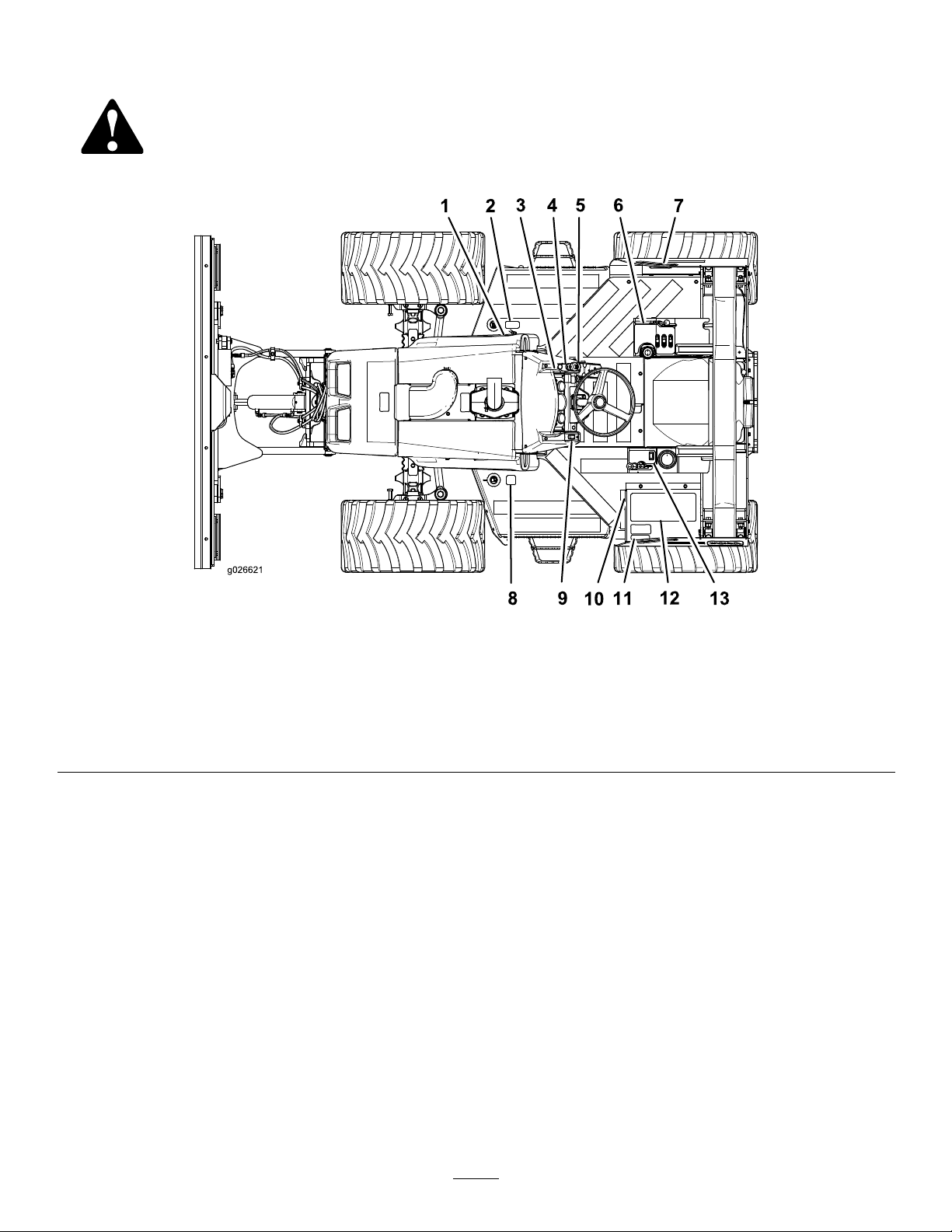
SafetyandInstructionalDecals
Safetydecalsandinstructionsareeasilyvisibletotheoperatorandarelocatednearanyareaofpotential
danger.Replaceanydecalthatisdamagedorlost.
Figure3
DecalMap(T opview)
1.Decal125-8470(underthe
hood)
2.Decal125-84836.Decal125-669510.Decal125-8473
3.Decal125-66837.Decal125-847111.Decal125-6691
4.Decal125-84848.Decal125-847812.Decal125-6699
5.Decal125-84729.Decal125-847513.Decal125-6698
7
Page 8
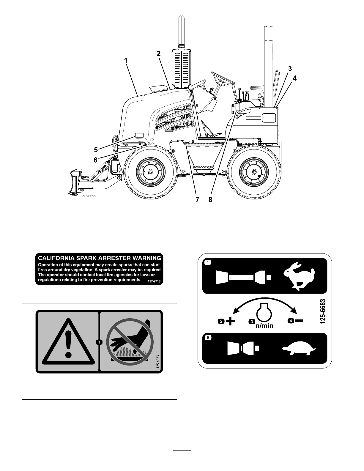
Figure4
DecalMap(Left-sideview)
1.Decal125-8479
2.Decal125-4963
1.Warning—donottouchhotsurfaces.
3.Decal125-8482(2)
4.Decal125-8481(2)
5.Decal125-84787.Decal125-6689
6.Decal117-27188.Decal125-8480
117-2718
125-6683
125-4963
1.Pulloutforfastestspeed
2.Increasespeed
3.Enginespeed
4.Decreasespeed
5.Pushinforslowestspeed
8
Page 9
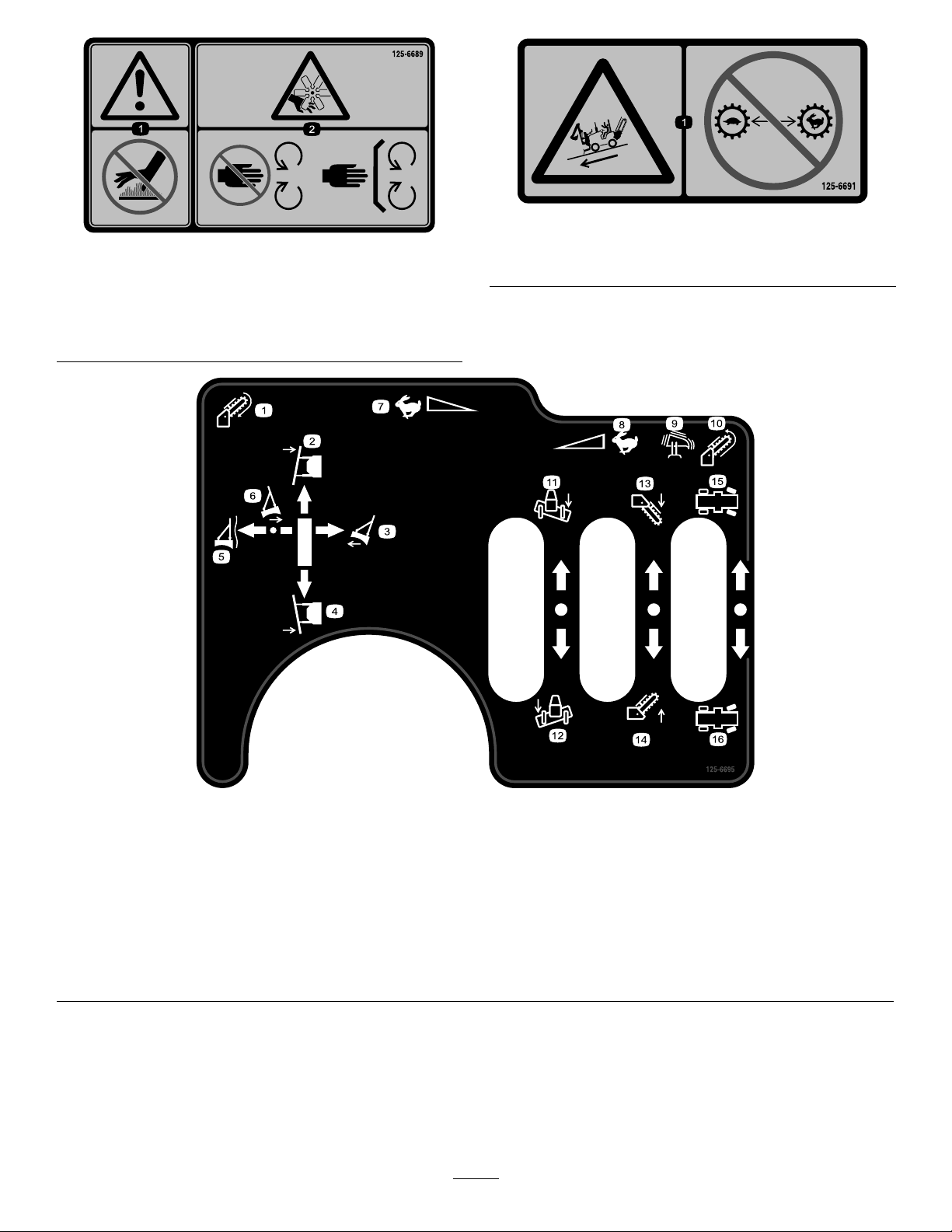
125-6691
1.Warning—keepawayfrom
hotsurfaces.
125-6689
2.Cutting/dismemberment
hazard,fan—keepaway
frommovingparts;keep
allguardsandsafety
devicesinplace.
1.Slopehazard—donotshiftgearswhilethemachineisona
slope.
125-6695
1.Trencherchain—forward
2.Backllblade—pivotleft
3.Backllblade—raise11.Backllblade—tiltright
4.Backllblade—pivotright12.Backllblade—tiltleft
5.Backllblade—oat
6.Backllblade—lower
7.Fastforward15.Rearsteeringleft
8.Fastreverse16.Rearsteeringright
9.Engagethevibratoryplow
10.Trencherchain—reverse
13.Trencher—lower
14.Trencher—raise
9
Page 10
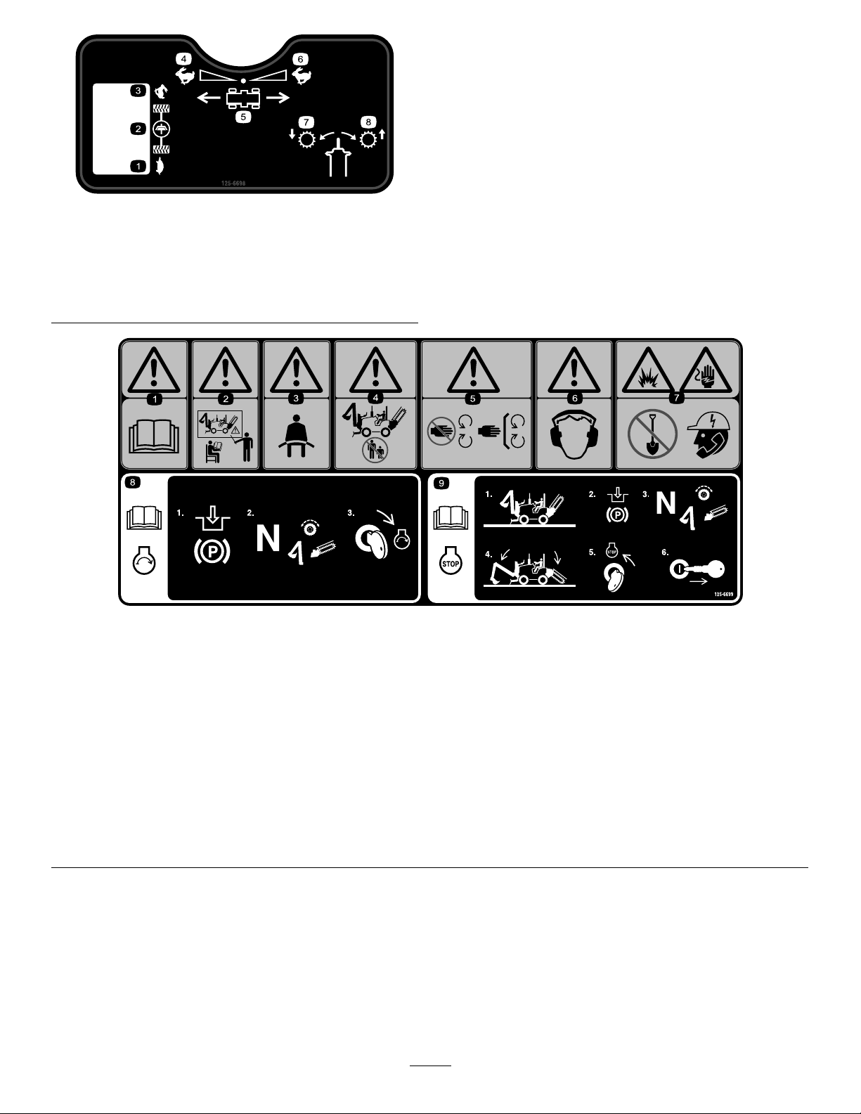
125-6698
1.Slow5.Machinedirectionof
2.Clutch
3.Fast
4.Fastforward8.Shift(highrange)
motion
6.Fastreverse
7.Shift(lowrange)
125-6699
1.Warning—readtheOperator’sManual.
2.Warning—donotoperatethemachineunlessyouaretrained.7.Explosionhazard;electricshockhazard—donotdiguntilyou
3.Warning—alwayswearaseatbeltwhenoperatingthe
machine.
4.Warning—keepbystandersawayfromthemachine.9.ReadtheOperator’sManualforinformationonstoppingthe
5.Warning—keepawayfrommovingparts;keepallguardsand
safetydevicesinplace.
6.Warning—wearhearingprotection.
havecalledlocalutilities.
8.ReadtheOperator’sManualforinformationonstartingthe
engine—1)Engagetheparkingbrake;2)Setthetractionand
attachmentstotheNeutralposition;3)Turnthekeytothe
engineStartposition.
engine—1)Parkthemachineonalevelsurface;2)Engage
theparkingbrake;3)Setthetractionandattachmentsthe
Neutralposition;4)Lowertheattachments;5)Turnthekeyto
theengineStopposition;6)Removethekeyfromtheignition.
10
Page 11
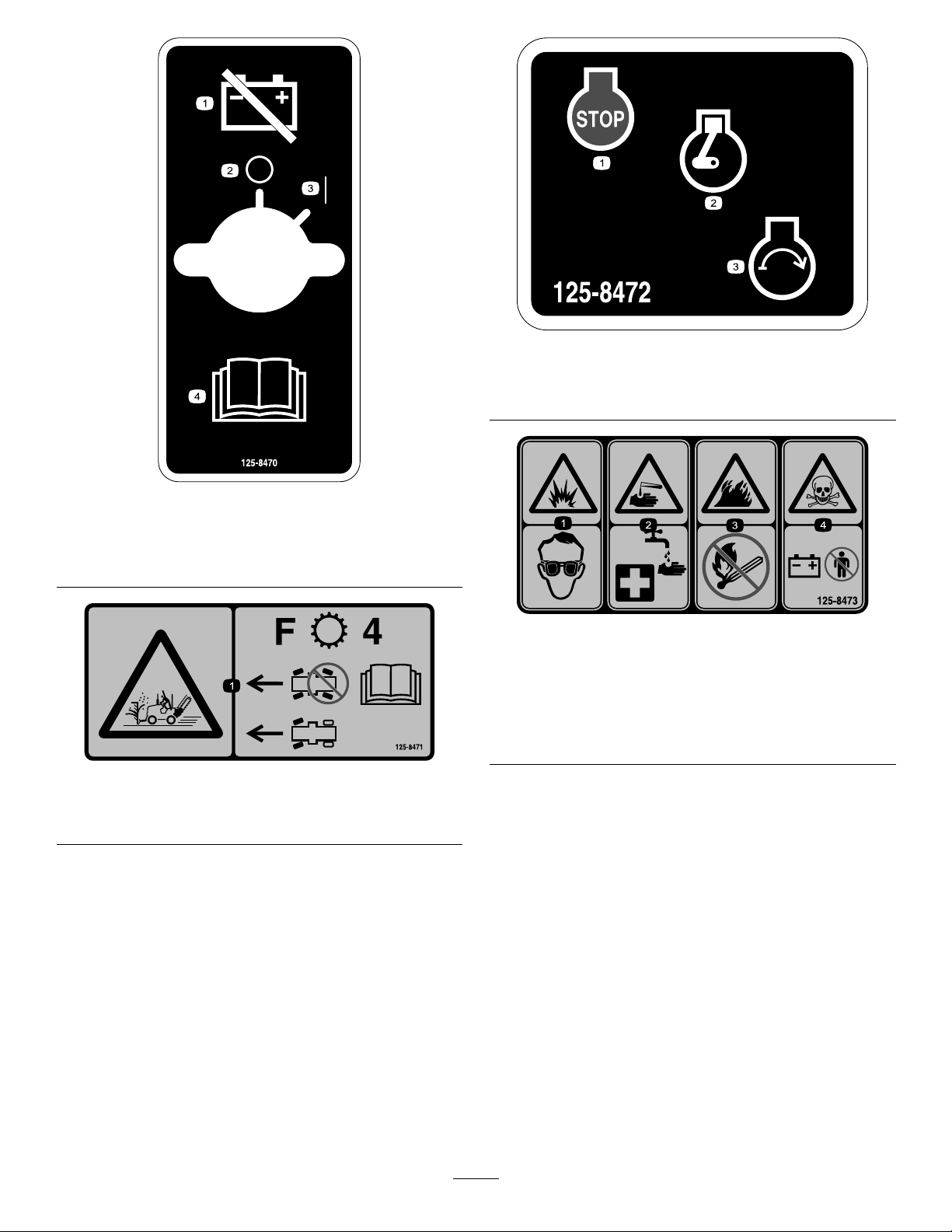
125-8472
1.Engine—stop3.Engine—start
2.Engine—run
125-8470
1.Disconnectthebattery.
2.Off
3.On
4.Warning—readthe
Operator’sManual.
125-8471
1.Usefrontwheelsteeringonlywhenmovingthemachine
forwardin4thgear.
1.Explosionhazard—wear
eyeprotection.
2.Chemicalburn
hazard—ushaffected
areawithwaterandseek
medicalhelp.
125-8473
3.Firehazard—keepopen
amesaway.
4.Poisonhazard—keep
childrenawayfromthe
battery.
11
Page 12
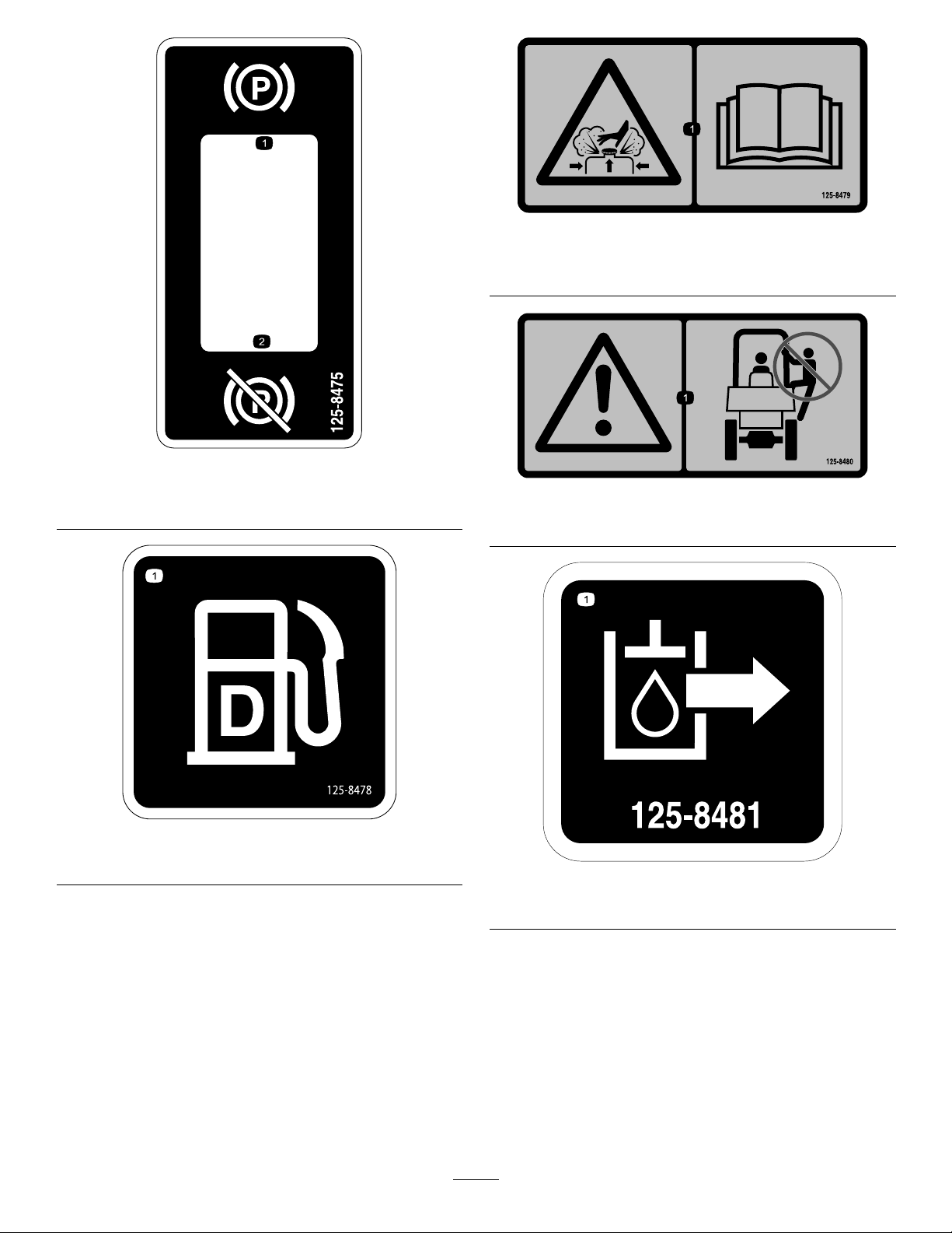
125-8479
1.Burnhazardfromcontentsunderpressure—readthe
Operator’sManual.
125-8475
1.Engagetheparkingbrake.2.Disengagetheparking
brake.
125-8478
1.Dieselfuel
125-8480
1.Warning—donotclimbonROPS.
125-8481
1.Hydraulicsupply
12
Page 13
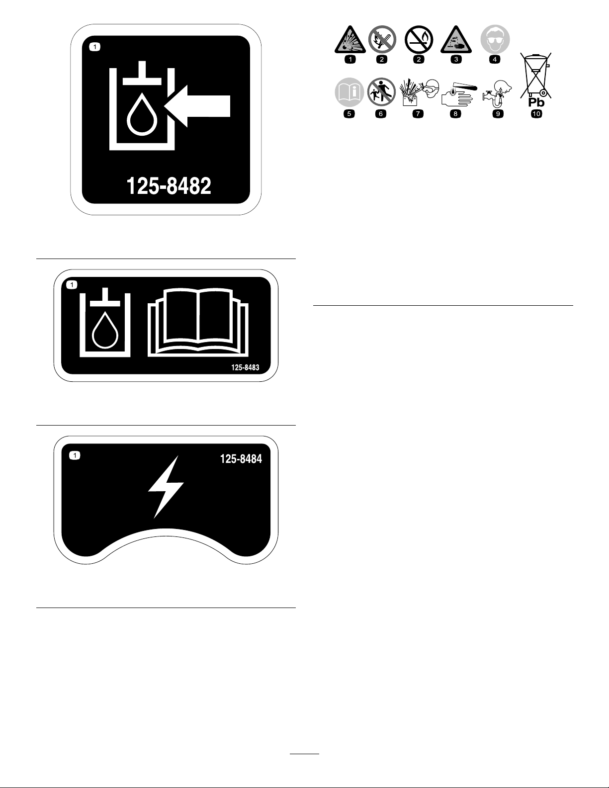
BatterySymbols
Someorallofthesesymbolsareonyourbattery .
125-8482
1.Hydraulicreturn
125-8483
1.ReadtheOperator’sManualforhydraulicoilinformation.
1.Explosionhazard
2.Nore,opename,or
smoking.
3.Causticliquid/chemical
burnhazard
4.Weareyeprotection9.Flusheyesimmediately
5.ReadtheOperator's
Manual.
6.Keepbystandersasafe
7.Weareyeprotection;
8.Batteryacidcancause
10.Containslead;donot
distancefromthebattery.
explosivegasescan
causeblindnessandother
injuries.
blindnessorsevereburns.
withwaterandgetmedical
helpfast.
discard
125-8484
1.12-voltreceptacle
13
Page 14
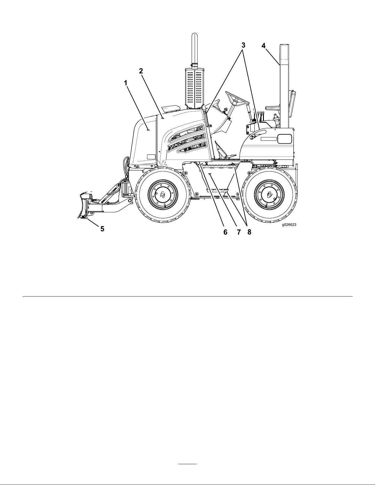
ProductOverview
Figure5
Leftsideofmachine
1.Nosepanel
2.Leftsidepanel6.Operatorwalkway
3.Grabhandles
4.ROPSenclosure8.Steps
5.Backllblade
7.Fuelreservoir
14
Page 15
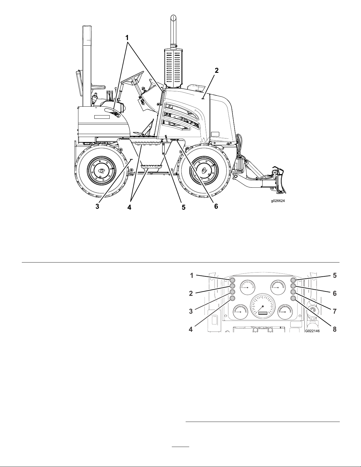
Rightsideofmachine
G022146
7
8
1
6
2
3
4
5
1.Grabhandles4.Steps
2.Rightsidepanel
3.Hydraulicuidtank
Controls
Becomefamiliarwithallthecontrols(Figure7)beforeyou
starttheengineandoperatethemachine.
InstrumentCluster
Thewarningandindicatinglights(excepttheengine-intake
preheatlight)comeonwhenyouturnthekeyswitchtothe
Runpositionbeforeyoustart.
Figure6
5.Hydraulicuidsightgauge
6.Hydraulic-tankcap
Figure7
InstrumentClusterLights
WarningLights
ThelocationsoftheselightsareshowninFigure7.
1.Engine-intakepreheat
light
2.Restricted
hydraulic-pressurelter
light
3.Restrictedair-cleanerlight7.Lowengine-oilpressure
4.Restrictedhydraulic-return
lterlight
15
5.Parking-brakesetlight
6.Controls-in-neutrallight
light
8.Lowhydraulic-pressure
light
Page 16
•Restrictedhydraulic-pressurelterlight—This
G022145
162 3 4 5
lightturnsonwhentheengineisrunningandthe
hydraulic-pressurelterisrestricted.Iftheengineis
runningandthislightturnson,stopthemachineand
replacethehydraulic-pressurelter.
•Restrictedair-cleanerlight—Thislightturnsonwhen
theengineisrunningandtheaircleanerisrestricted.If
theengineisrunningandthislightturnson,stopthe
engineandreplacetheair-cleanerelement.
•Restrictedhydraulic-returnlterlight—This
lightturnsonwhentheengineisrunningandthe
hydraulic-returnlterisrestricted.Iftheengineis
runningandthislightturnson,stopthemachineand
replacethehydraulic-returnlter.
•Lowengine-oilpressurelight—Thislightturnson
whentheengineisrunningandtheengine-oilpressure
isbelowthenormaloperatingrange.Iftheengineis
runningandthislightturnson,stoptheengineandcheck
theengine-oillevel.
•Lowhydraulic-pressurelight—Thislightturnson
whentheengineisrunningandthereisalossofhydraulic
pressure.Iftheengineisrunningandthislightturnson,
stoptheengine,checkthehydraulicuidlevel,andcheck
thehydraulicsystemforleaks.
IndicatingLights
ThelocationsoftheselightsareshowninFigure7.
•Engine-intakepreheatlight—Thislightturnsonwhen
youturnthekeyswitchtotheOnpositionandtheintake
airistoocoldtostarttheengine.Whentheintakeairis
warmenoughfortheenginetostart,thelightturnsoff,
andyoucanthenstarttheengine.
•Parking-brakesetlight—Thislightturnsonwhenyou
turnthekeytotheOnpositionandengagetheparking
brake.
•Controls-in-neutrallight—Thislightturnsonwhen
youturnthekeyswitchtotheOnpositionandthe
followingcontrolsareintheNeutralortheStopposition:
–Tractioncontrolpedal
–Utility-tractionlever
–Attachmentcontrollever
Gauges
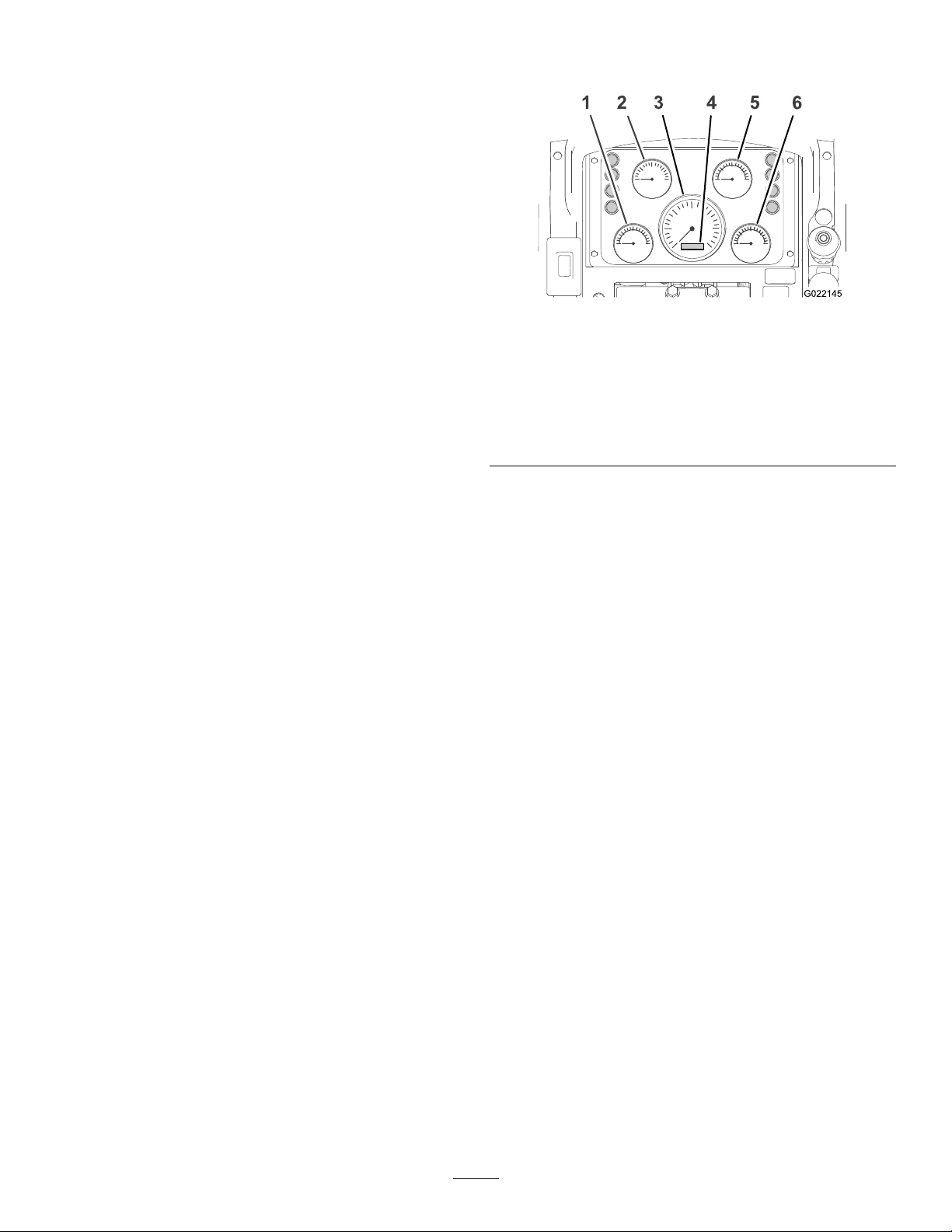
ThelocationsofthesegaugesareshowninFigure8.
Figure8
InstrumentClusterGauges
1.Engine-coolant
temperaturegauge
2.Voltmeter5.Fuel-levelgauge
3.Enginetachometer
4.Enginehourmeter
6.Hydraulic-uid
temperaturegauge
•Engine-coolanttemperaturegauge—Thisgauge
indicatesthetemperatureofthecoolantintheengine
coolingsystem.Thetemperaturerangesandthe
conditionsthattheyindicateareasfollows:
Note:Iftheneedleofthisgaugeindicatesthatthe
coolanttemperatureis116°C(241°F)orhigher,stopthe
engineandallowittocool.Thencheckthefollowing:
thecoolantlevel,theradiator(fordebrisinside),the
thermostat,andtheconditionofandtensiononthedrive
belt.
–82°C(179°F)orlower:Lowtemperature
–82to115°C(180°to240°F):Normaloperating
temperature
–116°C(241°F)orhigher:Hightemperature
•Voltmeter—Thisgaugeindicatesthevoltageofthe
batteryorofthebatteryandthealternator.Thevoltage
rangesofthevoltmeterindicatethefollowingconditions
abouttheelectricalsystem:
–11.4voltsorless:Lowvoltageforthebattery
–11.5to12.5volts:Normalvoltageforthebattery
–13.8to14.4volts:Normalvoltageforthebatteryand
thealternator(withthemachinerunning)
–14.5voltsormore:Highvoltageforthebatteryand
thealternator(withthemachinerunning)
Note:Youmuststoptheenginebeforeyoucheck
thechargingsystem.
•Enginetachometer—Thisgaugeindicatestheengine
speedinrevolutionsperminute(rpm).Eachnumberon
thegaugerepresents1000rpm,andeachspaceequals
200rpm.
•Enginehourmeter—Thisgaugeindicatesthetotal
numberofoperatinghoursofthemachinetoatenthof
16
Page 17
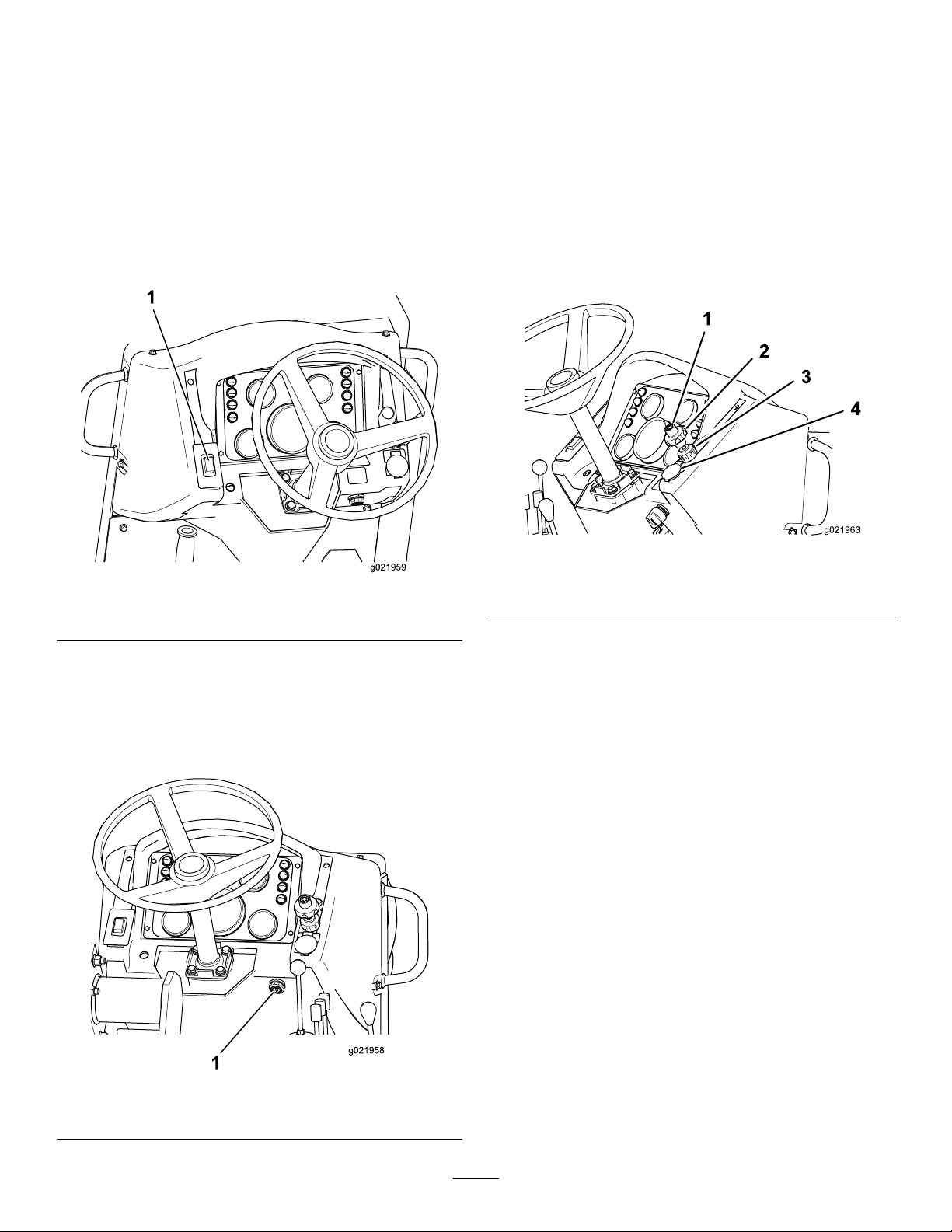
anhour.Usethehourmetertomeasuretheoperating
hoursbetweenmachineserviceintervals.
•Fuel-levelgauge—Thisgaugeindicatestheamountof
fuelinthefueltank.
•Hydraulic-uidtemperature—Thisgaugeindicatesthe
temperatureofthehydraulicuidinthesystem.
ParkingBrakeSwitch
•EngineStop—Turnthekeytothispositiontothe
stoptheengine,de-energizetheelectricalsystem,andto
removethekey.
•EngineRun—Turnthekeytothispositiontoenergize
theelectricalsystem.Thekeyreturnstothisposition
afteryoureleasethekeyfromtheStartposition.
•EngineStart—Turnthekeytothispositiontostartthe
engine.
Parkingbrakeswitch—Pushtheswitchuptoapplythe
parkingbrake(Figure9);pushtheswitchdowntorelease
theparkingbrakepedal.
Figure9
1.Parkingbrakeswitch
Note:Theparkingbrakeautomaticallyengageswhenthe
enginestops.
KeySwitch
Thekeyswitch(Figure10)hasthefollowing3positions:
ThrottleKnob
Usethethrottleknob(Figure11)tochangetheenginespeed
asfollows:
Figure11
1.Throttlebutton3.Throttlelock
2.Throttleknob4.Electricalsocket
•Pushthebuttonatthecenteroftheknobwhilepulling
theknobuptoincreasetheenginespeed.
•Pushthebuttonatthecenteroftheknobwhilepushing
theknobdowntodecreasetheenginespeed.
•Rotatetheknobcounterclockwisetomakeasmall
increaseintheenginespeed.
•Rotatetheknobclockwisetomakeasmalldecrease
intheenginespeed.
1.Keyswitch
ThrottleLock
Usethethrottlelock(Figure11)asfollowstoholdthethrottle
inpositionwhileyouareoperatingthemachine:
•Rotatethethrottlelockclockwisetolockthethrottlein
position.
•Rotatethelockcounterclockwisetoreleasethethrottle.
•Tightenthelocktopreventmoisturefromenteringthe
cableandtopreventthecablefromfreezingincold
weather.
12-voltElectricalSocket
Figure10
Usethe12-voltelectricalsocket(Figure11)topowerpersonal
electronicequipment,suchasacellphone,aradio,oraGPS
device.
17
Page 18
TractionControls
Important:Thetractioncontrolpedal,the
utility-tractionlever,andtheattachmentcontrollever
mustbeintheNeutralpositionbeforeyoucanstart
theengine.
Important:Youmustsitintheoperatorseattomove
thetractioncontrolsfromtheNeutralpositionandmove
themachine;otherwise,theenginewillstopin1second.
Note:Operationofthetractioncontrolpedaloverrides
operationoftheutility-tractionlever.
TractionControlPedal
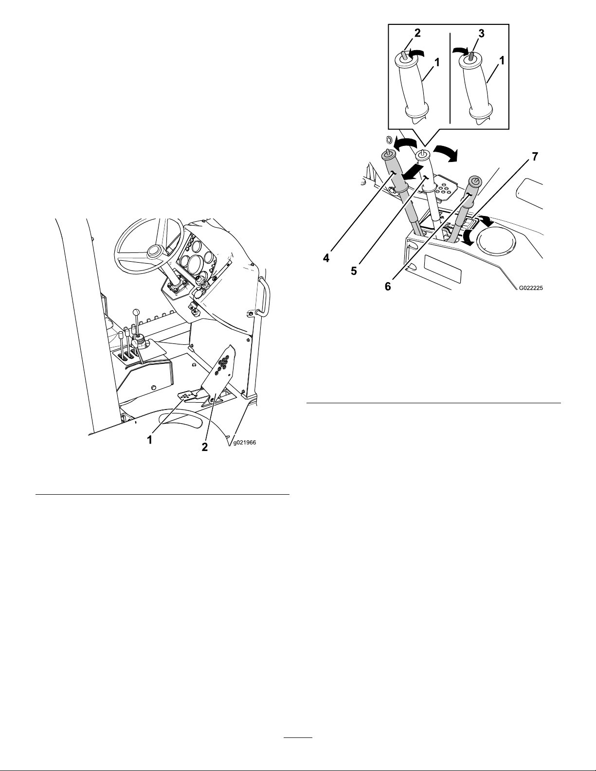
Thetractioncontrolpedal(Figure12)controlsthedirection
oftravelandthespeedofthemachine.
Figure13
Figure12
1.Heelpedal(reverse)2.Toepedal(forward)
Tocontrolthedirectionoftravelandthespeedofthe
machine,dothefollowing:
•Pushthetoepedalforwardtomovethemachine
forward.
•Pushtheheelpedaldowntomovethemachinein
reverse.
•Formaximumspeed,fullypushthepedal.
•Toreducethespeedofthemachineortostopthe
machine,movethepedaltowardtheNeutralposition.
1.Handle5.Utility-tractionlever
2.Drivemodeswitch
(transport)
3.Drivemodeswitch(work)
4.Utility-tractionlever
(forward)
(neutral)
6.Utility-tractionlever
(reverse)
7.Transmissionrangeswitch
Usetheutility-tractionleverasfollows:
•Tomovethemachineforward,pushtheleverforward
(awayfromyou).
•Tomovethemachinerearward,pulltheleverrearward
(towardyou).
Note:Thefartheryoupushorpullthelever,thefasterthe
machinemoves.
Note:Theleverlocksintopositionwhenyoureleasethe
lever.
DriveModeSwitch
Thedrivemodeswitch(Figure13)controlsthehydraulic
pressuretothetractionmotorandhas2positions:the
transportmodeandtheworkmode.
Important:Donotchangefromonedrivemodeto
anotherwhilethemachineismoving.
Utility-tractionLever
Note:TheNeutralpositionfortheutility-tractionleveris
detented.Youmustmovetheleveroutofthedetenttomove
theleverforwardorrearward.
Theutility-tractionlever(Figure13)has3positions:Forward,
Neutral,andReverse.
Note:Thedrivemodeswitchisusedinconjunctionwith
thetransmissionrangeswitch.
Tooperatethedrivemodeswitch,dothefollowing:
•Pulltheswitchrearward(towardyou)forworkmode.
•Pushtheswitchforward(awayfromyou)fortransport
mode.
18
Page 19
TransmissionRangeSwitch
•Pullthejoystickbacktoraisetheblade.
Thetransmissionrangeswitch(Figure13)isusedtocontrol
thegearreductionrangeofthetransmission,andithas2
positions(highandlow).
Important:Donotshiftbetweenthetransmission
rangeswhilethemachineismoving.
Note:Thetransmissionrangeswitchisusedinconjunction
withthedrivemodeswitch.
Tooperatethetransmissionrangeswitch,dothefollowing:
•Presstheswitchtotheright(nearyou)forlowrange.
•Presstheswitchtotheleft(awayfromyou)forhighrange.
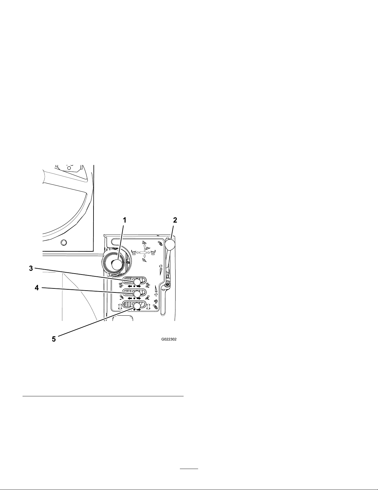
AttachmentControlPanel
Theattachmentcontrolpanelislocatedontherightsideof
theoperatorseat(Figure14).
•Pushthejoysticktotheright(awayfromyou)toswing
thebladetotheright.
•Pullthejoysticktotheleft(towardyou)toswingthe
bladetotheleft.
BackllBladeTiltLever
Usethebackllbladetiltlever(Figure14)totilttheblade.
Operatetheleverasfollows:
•Pushthislevertotheright(awayfromyou)totiltthe
bladedownontheright.
•Pullthecontrollevertotheleft(towardyou)totiltthe
bladedownontheleft.
AttachmentControlLever
Note:Usetheattachmentcontrollever(Figure14)forthe
trencher.
Operatethecontrolleverasfollows:
•Pushthislevertotheright(awayfromyou)tolowerthe
attachment.
•Pullthelevertotheleft(towardyou)toraisethe
attachment.
1.Backll-bladejoystick
2.Trencherchain
direction/cableplowspeed
control
3.Backlltiltcontrol
Figure14
4.Attachmentcontrol
5.Rear-wheelsteering
control
Note:Whenyoureleasethelever,themachinemaintains
theattachmentposition.
RearWheelSteeringControlLever
Usetherearwheelsteeringcontrollever(Figure14)tosteer
therearwheels.
•Pushthelevertotheright(awayfromyou)toturnthe
rearwheelstotheright.
•Pullthelevertotheleft(towardyou)toturntherear
wheelstotheleft.
Note:Youcanturnthefrontwheelsbyusingthesteering
wheelonly.
RearAttachmentControlLever
Therearattachmentcontrolleverislocatedontherightside
oftheoperatorseatasshowninFigure15.
BackllBladeJoystick
Usethebackllbladejoystick(Figure14)tooat,raise,lower,
andanglethebackllblade.Operatethejoystickasfollows:
•Pushthejoystickpartiallyforwardtolowertheblade.
•Pushthejoystickallthewayforwardtooattheblade.
19
Page 20
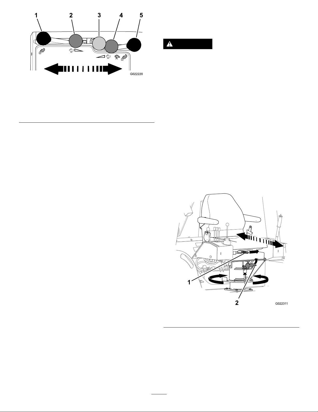
Figure15
1.Fastforwardchainspeed4.Slowreversechainspeed
2.Slowforwardchainspeed
3.Neutralposition
orslowplowvibration
5.Fastreversechainspeed
orfastplowvibration
OperatorSeatandSeatBelt
SeatInterlockSystem
WARNING
Theseatinterlocksystemprotectstheoperator
frominjury.
Donotdisabletheseatinterlocksystem.
Theseatinterlocksystemrequirestheoperatortositinthe
operatorseatwhileoperatingthismachine.
Note:Theneutralindicatorlightturnsonwhenyouturnthe
keyswitchtotheOnpositionandboththeutility-traction
controlandattachmentcontrolleversareintheNeutral
position.
•Cableplowoperation(optional)—movethecontrol
levertocontrolthecableplowasfollows:
–Movethecontrolleverrearwardtoactuatethe
vibrationoftheblade;movethecontrolleverfully
rearwardtoincreasethevibration.
–MovethecontrollevertotheNeutralpositionto
decreaseandstopthevibration.
Note:Movingthecontrolleverforwardbeyondthe
Neutralpositionhasnofunction.
•Trencheroperation—movethecontrollevertocontrol
thetrencherasfollows:
–Movethecontrolleverforwardtoactuatethedigging
chainintheforwarddirection.
–Movethecontrolleverfullytowardthefrontto
increasethechainspeed.
–MovethecontrollevertotheNeutralpositionto
stopthechain.
–Movethecontrolleverrearwardtoreversethe
diggingchaindirection.
Note:Youmustsitintheoperatorseattomovethe
attachmentcontrolleverfromtheNeutralposition;
otherwise,theenginewillstopin1second.
Note:Iftheoperatordoesnotremainseatedwhenthe
utility-tractionleverisnotintheNeutralposition,theengine
willstopin1second.Donotlayaheavyobjectontheseator
tamperwiththeseatinterlocksysteminanyway.
ForwardandRearwardSeatControl
Tomovetheoperatorseat(Figure16)forwardorrearward,
pullthecontrolbartothelefttoadjusttheseatforwardor
rearward.
Figure16
1.Controlbar2.Seatlever
SeatPivotControl
Torotatetheseat,pulltheseatleverupandrotatetheseat
tothedesiredposition.
20
Page 21
SeatBelt
Specications
WARNING
Operatingthemachinewithouttherollover
protectionsystem(ROPS)securelyinplacecan
resultinseriousinjuryordeathifthemachinerolls
over.
•Ensurethattherollbarissecurelyinplace.
•AlwayswearaseatbeltwiththeROPSinplace.
•Ensurethattheoperatorseatisproperlysecured
tothemachine.
Note:Regulationsinsomelocalitiesrequirethatseatbeltson
constructionmachinesbe76mm(3inch)wide.Checkwith
localauthoritiesregardingtherequirementsforseatbelts.
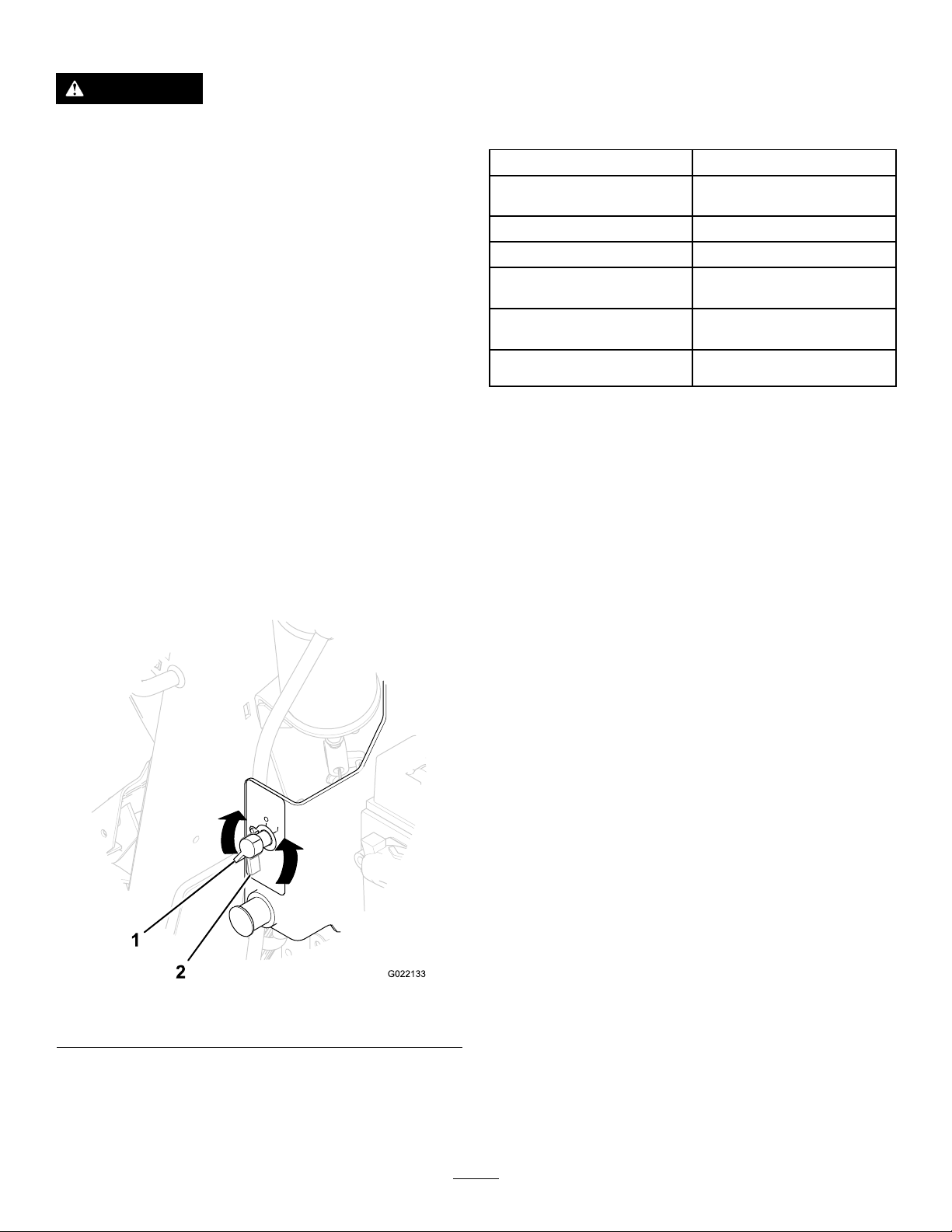
•Tofastentheseatbelt,insertthetabendintotheleft
buckle.
Note:Ensurethatthetabendandthebuckleare
securelyfastened.
•Toreleasetheseatbelt,pushthebuttononthebuckle.
Battery-disconnectSwitch
Thebattery-disconnectswitchislocatedbehindtheright
enginecowl(Figure17);useittoelectricallydisconnectthe
batteryfromthemachine.
Note:Specicationsanddesignaresubjecttochange
withoutnotice.
BasicMachineDimensionsandWeightData
Wheelbase
Overallheight(tothetopof
theROPS)
Overallwidth(atthetires)170.2cm(67.0in)
Minimumgroundclearance
Turningradius(2-wheel
steering)
Turningradius(4-wheel
steering)
Weight(withoutattachments)2,494kg(5,500lb)
149.8cm(59.0in)
243.8cm(96.0in)
30.5cm(12.0in)
464.8cm(183in)
294.6cm(1 16in)
Attachments/Accessories
AselectionofToroapprovedattachmentsandaccessoriesis
availableforusewiththemachinetoenhanceandexpand
itscapabilities.ContactyourAuthorizedServiceDealeror
Distributororgotowww .Toro.comforalistofallapproved
attachmentsandaccessories.
Figure17
1.BatteryOnposition2.BatteryOffposition
•RotatethebatterydisconnectclockwisetotheOn
position.
•Rotatethebatterydisconnectcounterclockwisetothe
Offposition.
21
Page 22

Operation
coldowcharacteristics,whichaidinstartingtheengineand
helppreventcloggingthefuellter.
Note:Determinetheleftandrightsidesofthemachine
fromthenormaloperatingposition.
PreparingforWork
Beforeoperatingthemachineonthejobsite,reviewthe
followingitems:
•Gatherallrelevantinformationavailableaboutthejob
sitebeforeyoubeginworking.
•Reviewallblueprintsandotherplans,andidentifyall
existingorproposedstructures,characteristicsofthe
landscape,andotherproposedjobsintheareascheduled
atthesametimeasyourjob.
Notethefollowingitemsatthejobsite:
–Changesinelevationintheproposedworkarea
–Theconditionandtypeofsoilintheproposedwork
area
–Locationsofstructures,water,railroadtracks,and
otherobstructionsthatyouwillneedtoworknear
oraround
–Utilitymarkers,meters,andpoles
–Iftheworksiteisnearoronaroadwaywithtrafc,
callthelocalauthoritiesregardingpropersafety
proceduresandregulations.
–Accesstothesite
•CallyourlocalOne-Callservice(811intheUS)orthe
One-Callreferralnumber(888-258-0808intheUSand
Canada)andasktheparticipatingutilitycompaniesto
locateandmarktheirundergroundutilitylines.Alsocall
utilityprovidersthatarenotpartoftheOne-Callsystem.
AddingFueltotheEngine
Useultra-lowsulfurdiesel(ULSD)fuelintheengine.Using
otherfuelscancausealossofenginepowerandhighfuel
consumption.
Important:Donotusekeroseneorgasolineinsteadof
dieselfuel;otherwise,youwilldamagetheengine.
UseonlydieselfuelforthemachinethatmeetsSpecication
D975oftheAmericanSocietyforTestingandMaterials
International.Seeyourdieselfueldistributor.
Useonlyclean,freshdieselfuelorbiodieselfuelswithlow
(<500ppm)orultralow(<15ppm)sulfurcontent.The
minimumcetaneratingshouldbe40.Purchaseonlyenough
fuelthatyouexpecttousewithin30daystoensurethatit
staysfresh.
Fueltankcapacity:75.7L(20USgal)
Usesummer-gradedieselfuel(No.2-D)attemperatures
above20°F(-7°C)andwinter-gradedieselfuel(No.1-Dor
No.1-D/2-Dblend)below20°F(-7°C).Usingwinter-grade
fuelatlowertemperaturesprovidesalowerashpointand
Usingsummer-gradefuelabove20°F(-7°C)contributes
towardalongerfuelpumplifeandincreasedpowercompared
tousingwinter-gradefuel.
WARNING
Fuelisharmfulorfatalifswallowed.Long-term
exposuretofuelvaporscancauseseriousinjury
andillness.
•Avoidprolongedbreathingofvapors.
•Keepyourfaceawayfromnozzleandfueltank
orconditioneropening.
•Keepfuelawayfromyoureyesandskin.
DANGER
Incertainconditions,fuelisextremelyammable
andhighlyexplosive.Areorexplosionfromfuel
canburnyouandothersandcandamageproperty.
•Fillthefueltankoutdoorsinanopenareawhen
theengineiscold.Wipeupanyfuelthatspills.
•Neverllthefueltankinsideanenclosedtrailer.
•Neversmokewhenhandlingfuel,andstayaway
fromanopenameorwherefuelfumesmaybe
ignitedbyaspark.
•Storefuelinanapprovedcontainer,andkeep
itoutofthereachofchildren.Neverbuymore
thana30-daysupplyoffuel.
•Donotoperatewithoutentireexhaustsystemin
placeandinproperworkingcondition.
Incertainconditions,fuelingcanreleasestaticelectricityand
causeaspark,whichcanignitethefuelvapors.Areor
explosionfromfuelcanburnyouandothersandcandamage
property.
•Alwaysplacefuelcontainersontheground,awayfrom
yourvehiclebeforelling.
•Donotllfuelcontainersinsideavehicleoronatruck
ortrailerbed,becauseinteriorcarpetsorplastictruck
bedlinersmayinsulatethecontainerandslowtheloss
ofanystaticcharge.
•Whenpractical,removetheequipmentfromthetruck
ortrailer,andrefueltheequipmentwithitswheelson
theground.
•Ifrefuellingtheequipmentwithitswheelsontheground
isnotpossible,thenrefuelsuchequipmentonatruckor
trailerfromaportablecontainerratherthanfromafuel
dispensernozzle.
•Ifyoumustuseafueldispensernozzle,keepthenozzlein
contactwiththerimofthefueltankorcontaineropening
atalltimesuntilfuelingiscomplete.
22
Page 23
UsingBiodieselFuel
°C°C-40
-30 -20 -10 0 10 20 30 40 50
-40 -22 -2 14 32 50 58 86 104 122
All Seasons
Winter Conditions
Arctic Conditions
°C°C-40
-30 -20 -10 0 10 20 30 40 50
-40 -22 -2 14 32 50 58 86 104 122
15W -40
10W -30
5W-30
G022415
Thismachinecanalsouseabiodieselblendedfuelofup
toB20(20%biodiesel,80%petrodiesel).Thepetrodiesel
portionshouldbeloworultra-lowsulfur.Observethe
followingprecautions:
•Thebiodieselportionofthefuelmustmeetspecication
ASTMD6751orEN14214.
•TheblendedfuelcompositionshouldmeetASTMD975
orEN590.
•Biodieselblendsmaybedamagepaintedsurfaces.
•UseB5withabiodieselcontentof5%orlessincold
weather.
•Checkseals,hoses,gasketsthatcomeincontactwiththe
fuel,astheymaydegradeovertime.
•Thefuelltermaybecomepluggedforatimeafter
convertingtoabiodieselfuelblend.
•Contactyourdistributorformoreinformationabout
biodieselfuel.
StoringFuel
Ifyoustorefuelinastoragetank,itcanaccumulateforeign
materialorwater.Keepthefuelstoragetankoutside,and
keepthefuelascoolaspossible.Removewaterfromthefuel
inthestoragecontaineratregularintervals.
Note:Removethecapslowlytoreducetheair
pressurebuildup.
2.Fillthefueltanktothebottomofthenecktoallow
thefuelroomtoexpand.
Note:Thefueltankcapacityis75.7L(20USgal).
3.Installthefueltankcapandtightenitsecurelybyhand.
CheckingtheEngineOilLevel
ServiceInterval:Beforeeachuseordaily
Theengineisshippedwithoilinthecrankcase;however,
checktheoillevelbeforeandafteryourststarttheengine.
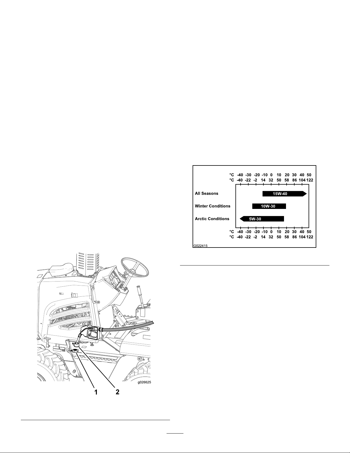
Useonlyhigh-qualitySAE15W -40heavy-dutyengineoilwith
anAPIclassicationofCH-4orhigher.
WhileSAE15W-40oilwithanAPIclassicationofCH-4or
higherisrecommendedformostclimates,refertoFigure19
foroilviscosityrecommendationsforextremeclimates.
FillingtheFuelTank
Note:Fillthefueltankofthemachineattheendofeachday
topreventcondensationinthefueltank.
1.Cleanaroundthefuel-tankcap(Figure18),andremove
thecapfromthetank.
Figure19
Note:Limiteduseoflow-viscosityoilssuchasSAE10W-30
withanAPIclassicationofCH-4orhighercanbeusedfor
easierstartingandprovidingsufcientoilowatambient
temperaturesbelow-5°C(23°F).However,continuoususeof
lowviscosityoilcandecreaseenginelifebecauseofwear.
ToroPremiumEngineOilisavailablefromanAuthorized
ToroServiceDealerineither15W -40or10W-30viscosity
withAPIclassicationCH-4orhigher.SeethePartsCatalog
forpartnumbers.Also,refertotheEngineOperator'sManual,
includedwiththemachine,forfurtherrecommendations.
Important:Iftheoillevelinthecrankcaseistoolow
ortoohighandyouruntheengine,youmaydamage
theengine.
1.Removetheright-sidepanel;refertoRemovingthe
SidePanels(page35).
1.Fuelcap2.Fillerneck
Figure18
2.Removethedipstick(Figure20)andwipeitcleanwith
acleancloth(Figure20).
23
Page 24
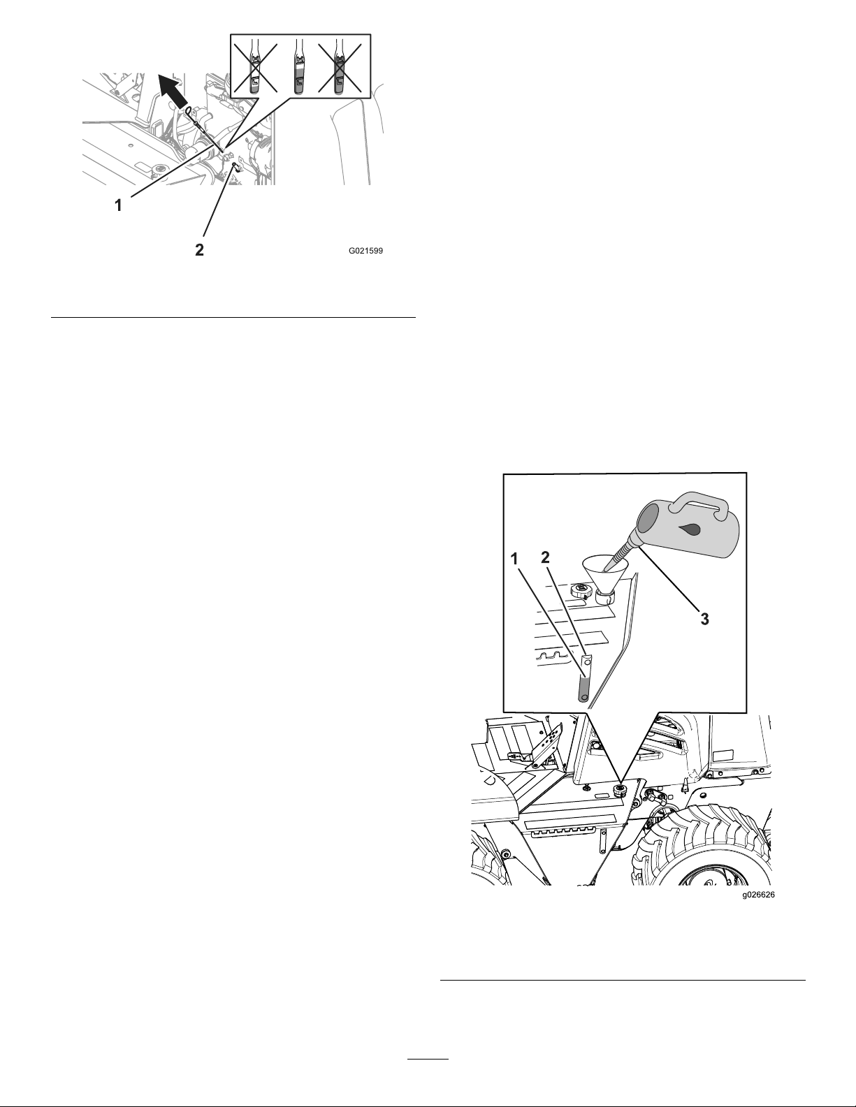
Figure20
1.Dipstick2.Dipsticktube
3.Insertthedipstickfullyintothedipsticktube,then
removethedipstick(Figure20).
4.Readtheoillevelonthedipstick.
•Iftheoillevelistoolow,slowlypourasmall
amountofthespeciedoilintotheoil-llerneck
(Figure43),wait3minutes;refertostep1inFilling
theEnginewithOil(page39).
HighViscosityIndex/LowPourPointAnti-wear
HydraulicFluid,ISOVG46(cont'd.)
PourPoint,ASTMD97-37°C(-34°F)to-45°C(-49°F)
FZG,Failstage
Watercontent(newuid)500ppm(maximum)
IndustrySpecications:VickersI-286-S(QualityLevel),
VickersM-2950-S(Quality
Level),DenisonHF-0
11orbetter
Note:Manybrandsofhydraulicuidsarealmostcolorless,
makingitdifculttospotleaks.Areddyeadditiveforthe
hydraulicsystemoilisavailablein20ml(0.68oz)bottles.
Onebottleissufcientfor15.1to22.7L(4.0to6.0USgal)
ofhydraulicoil.Orderpartno.44-2500fromanAuthorized
ToroServiceDealer.
1.Parkthemachineonalevelsurface,andputallthe
attachmentsinthetransportposition.
2.Stoptheengine,settheparkingbrake,andremovethe
ignitionkey .
3.Checkthehydraulicuidlevelinthesightgauge
locatedatthesideofthehydraulicreservoir(Figure21).
•Iftheoillevelistoohigh,draintheexcessoiluntil
youobtainthecorrectoillevelonthedipstick;
refertoDrainingtheEngineOil(page38).
5.Repeatsteps2through4untiltheoilleveliscorrect.
6.Installthedipstickandoil-llcapsecurely.
7.Installtheright-sidepanel;refertoInstallingtheSide
Panels(page36).
CheckingtheHydraulicFluid Level
ServiceInterval:Beforeeachuseordaily
UseToroPremiumAll-seasonHydraulicFluid(available
in5-gallonpailsor55-gallondrums.Seethepartscatalogor
anAuthorizedT oroServiceDealerforpartnumbers).
IfTorohydraulicuidisnotavailable,youmayusean
equivalenthydraulicuid,providedthatitmeetsallthe
followingmaterialpropertiesandindustryspecications.Do
notuseasynthetichydraulicuid.Consultwithyour
lubricantdistributortoidentifyasatisfactoryproduct.
HighViscosityIndex/LowPourPointAnti-wear
HydraulicFluid,ISOVG46
MaterialProperties:
ViscosityIndexASTM
D2270
St@40°C(104°F):44to48 Viscosity,ASTMD445
St@100°C(212°F):7.9to8.5
140to160
Figure21
1.Filllevel(midpoint)3.Hydraulicuid
2.Sightgauge
Note:Thehydraulicuidlevelshouldbebetweenthe
AddandFullmarksonthesightgauge.
24
Page 25

4.IfthehydraulicuidlevelisbelowtheAddmark,
removethellcap(Figure21),addthespecied
hydraulicuidtoraisetheuidleveluptotheFull
mark,andinstallthellcap.
InspectingtheMachineDaily
Inspectthefollowingitemsonthemachineeachdaybefore
youstarttheengine:
•Checkforleaksunderthemachine,andrepairallleaks.
•Checkthetiresforwear,damage,andlowpressure.
•Checkthemachinefordebris,especiallyaroundthe
engine.
Note:Ensurethattheareaneartheengineiscleanso
thattheenginecoolsproperly.
•Cleanorreplaceanysafetyorinstructionaldecalthat
cannotberead.
•Cleanmachinecomponentsthatyou,theoperator,use.
•Removeanylooseitemsfromthemachine.
•Checkthemachineforbroken,damaged,loose,or
missingparts.Replace,tighten,oradjusttheseparts
beforeyouoperatethemachine.
•RepairorreplacealldamagedROPSandseatbeltparts.
StartingtheEngine
WARNING
Beforestartingtheengine,sitintheoperatorseat,
fastentheseatbelt,applytheparkingbrake,and
ensurethatthetransmissiondirectioncontroland
diggingcontrolleversareintheNeutralposition.
Warnallpersonsaroundyouthatyouarestarting
theengine.
Note:Theseatinterlocksystempreventsyoufromstarting
andoperatingthemachineunlessyouraresittinginthe
operatorseat.Ifyoudonotremainseatedandthecontrol
leversarenotintheNeutralposition,thesystemwillstop
boththegrounddriveandtheattachmentdrivein1second.
Donotsetaweightedobjectontheseat,bypasstheseat
interlocksystem,ortamperwiththesystem.
1.Checktheoillevel;refertoCheckingtheEngineOil
Level(page23).
2.Ensurethatthebattery-disconnectswitchisintheOn
position.
3.Adjusttheseatpositionandfastentheseatbelt.
Note:Ensurethattheseatisfacingforward.
4.SettheparkingbrakeswitchtotheOnposition.
5.EnsurethatallcontrolleversareintheNeutralorthe
StoppositionandthatthehandthrottleisintheIdle
position.
Note:Thecontrols-in-neutrallightwillilluminate.
Note:Ifthemachineisequippedwithabackhoe,
ensurethattheengineshutoffcontrolispulledup.
6.Pullthethrottleleverouttothe1/2Throttleposition.
Note:Inextremehotorcoldweather,takethe
necessaryprecautions;refertoOperatingtheMachine
inExtremeConditions(page26).
7.TurnthekeyswitchtotheOnposition,andcheckthat
thecontrols-in-neutral,theparking-brakewarning,and
theoil-pressurewarninglightsilluminate.
Note:Theenginecomeswithanglowplugair
systemthatsensetheinletairtemperature.Iftheair
temperatureiscold,thewait-to-startwarninglight
alertstheoperatortowaitfortheintakeairtowarmup
beforestarting.Whentheintakeairisattheproper
temperatureforstartingtheengine,thewarninglight
turnsoff.
8.TurnthekeyswitchhalfwaybetweentheOnand
Startpositions,andcheckthatthewarninglightson
theinstrumentclusterareworkingproperly;referto
InstrumentCluster(page15).
9.TurnthekeyswitchtotheStartposition.
Note:Iftheenginestartsandthenstops,donot
turnthekeyswitchtotheStartpositionagainuntilthe
startermotorhasstoppedturning.
Important:
itstopsturning.
formorethan30secondsatonetime.Allowthe
startermotortocoolfor30secondsbeforeyou
operateitagain.Whenyouengagethestarter
motor,youshouldseewhiteorblacksmoke
comingfromtheexhaustpipe;ifyoudonot,check
thefuelsupply.
10.Whentheenginestarts,checktheinstrumentsto
ensurethatthegaugereadingsarecorrect.Ifanyof
thewarninglightsturnon,stoptheengineandcheck
theproblem.
11.Runattheengineat1000rpmuntilthecoolantis
warm.
12.Cycleallthemachinecomponentsbeforeoperatingthe
machine,andcheckallthecontrolsandcomponentsto
ensurethattheyareworkingproperly.
Note:Iftheengineisnewornewlyrebuilt,referto
BreakinginaNeworRebuiltEngine(page26).
Do not
operatethestartermotoruntil
Do not
operatethestartermotor
SettingtheEngineSpeed
Note:Donotruntheengineatalowidlespeedforlong
periodsoftime,becauseitcausesalowoperatingtemperature
thatcanallowacidsanddepositstoformintheengineoil.
Note:Formaximumlifeandmachineperformance,operate
theengineatfullthrottlewhenevertheconditionsallowyou
tosafelydoso.
25
Page 26
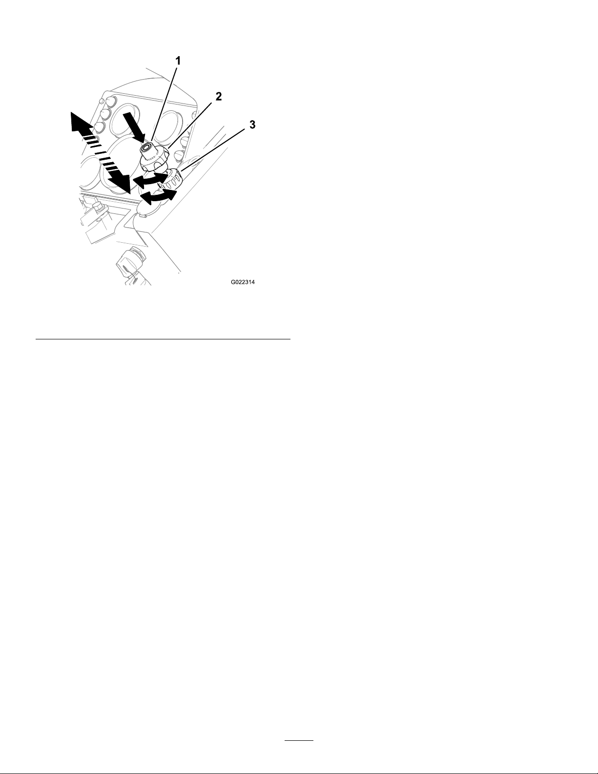
•Toincreasetheenginespeed,pushthethrottlecenter
buttonwhilepullingoutthethrottle(Figure22).
Figure22
BreakinginaNeworRebuilt Engine
Duringtherst20hoursofoperationofaneworrebuilt
engine,dothefollowing:
•Keeptheengineatanormaloperatingtemperature.
•Donotruntheengineatlowidlespeedsforlongperiods
oftime.
•Operatethemachinewithnormalloadsfortherst8
hours.
•Donotusespecial“break-in”lubricatingoil.Usethe
speciedoil;refertoCheckingtheEngineOilLevel(page
23)andChangingtheEngineOilFilter(page39).
OperatingtheMachinein ExtremeConditions
Bothhotandcoldweatherplaceunusualdemandsupon
themachineandtheattachments.Youcanminimize
temperature-relatedproblemsonthemachinebyperforming
thefollowingsteps:
1.Throttlebutton3.Throttlelock
2.Throttleknob
•Todecreasetheenginespeed,pushthethrottlecenter
buttonwhilepushinginthethrottle.
•Tonelyincreasetheenginespeed,rotatethethrottle
knobcounterclockwise.
•Tonelydecreasetheenginespeed,rotatethethrottle
knobclockwise.
StoppingtheEngine
1.Parkthemachineonlevelground,ifpossible.
Important:Ifyoumusttemporarilyparkthe
machineonaslopeoranincline,positionthe
machineatarightangletotheslope,withthe
frontofthemachinetowardthebottomofthehill.
Ensurethatthemachineisbehindanobjectthat
willnotmove.
2.Supportorlowerallattachmentstotheground.
3.Settheparkingbrake.
HotWeather
1.Cleanalldirtanddebrisfromtheradiator,hydraulicoil
cooler,andengineareatoensurethatthereisproper
airowtocooltheengine.
2.Wipeanydebrisfromtheairinletsinthehoodside
panels.
3.Uselubricantsthathavethecorrectviscosity.
4.Checktheaircleanerdustvalvemorefrequentlyin
extremelydustyconditions.
5.Checktheconditionofthefandrivebelt.Replaceitif
itiscrackedorworn.
6.Operatethemachineatanappropriateenginespeed
andtransmissionrangefortheoperatingconditions;
donotoverloadtheengine.
7.Testtheradiatorcapbeforethehotweatherbegins;
replacethecapifitisdamaged.
8.Maintainthecorrectcoolantlevelinthereservoirand
intheradiator,andensurethatthereisamixtureof
50%ethyleneglycoland50%waterinthecooling
system.
ColdWeather
4.Ifthemachinehasbeenoperatingunderaheavyload,
decreasetheenginespeedto1/4throttlefor2minutes
toevenlycooltheengine.
5.PushthethrottlelevertotheSlowposition,andturn
thekeyswitchtotheOffposition.
6.Ifyouleavethemachineunattended,removethekey
fromtheignitionswitch.
Operatingyourmachineincoldweatherrequiresspecial
attentiontopreventseriousdamagetothemachine.
Performingthefollowingprocedureswillextendtheservice
lifeofyourmachine:
1.Cleanthebatteryandensurethatitisfullycharged.
Note:Afullychargedbatteryat-17ºC(0ºF)has
only40%ofthenormalstartingpower.Whenthe
temperaturedecreasesto-29ºC(-20ºF),thebatteryhas
only18%ofthenormalpowerremaining.
26
Page 27
2.Themachinecomeswithamaintenance-freebattery.
Ifyouuseadifferentbatteryandaddwatertoitwhen
thetemperatureisbelow0ºC(32ºF),ensurethatyou
chargethebatteryorruntheengineforabout2hours
topreventthebatteryfromfreezing.
3.Inspectthebatterycablesandterminals.Cleanthe
terminals,andapplyacoatofgreaseoneachterminal
topreventcorrosion.
4.Ensurethatthefuelsystemiscleanandfreeofwater.
Usetheproperfuelforcoldweather.
Note:Preventwaxandcondensationfrombuilding
upinthefueltankbyllingupthefueltankattheend
ofeachday.
5.Checkthecoolantmixturebeforeyouoperatethe
machineincoldweather.Useonlya50%ethylene
glycoland50%watermixtureinthecoolingsystem
yearround.
DrivingandStoppingthe Machine
UsingtheTractionControlPedal
Thetractioncontrolpedalcontrolsthedirectionoftravel
andthespeedofthemachine.
•Tomovethemachineforward,pushdownonthetoe
pedal.
•Tomovethemachineinreverse,pushdownontheheel
pedal.
Note:T oincreasethespeed,pushdownfartheronthe
pedal;todecreasethespeed,allowthepedaltomoveup
towardtheNeutralposition.
UsingtheUtility-tractionLever
6.Beforeoperatingthemachine,moveitatlowspeed
andactuateeachhydrauliccontrolseveraltimesto
warmtheoil.
Important:Theengineandthehydraulicsystem
mustbeatoperatingtemperaturebeforeyou
performanyworkwithit.
Note:Keepthediggingchainfreeofmudandsnow
topreventitfromfreezingafteroperation.
OperatingtheParkingBrake
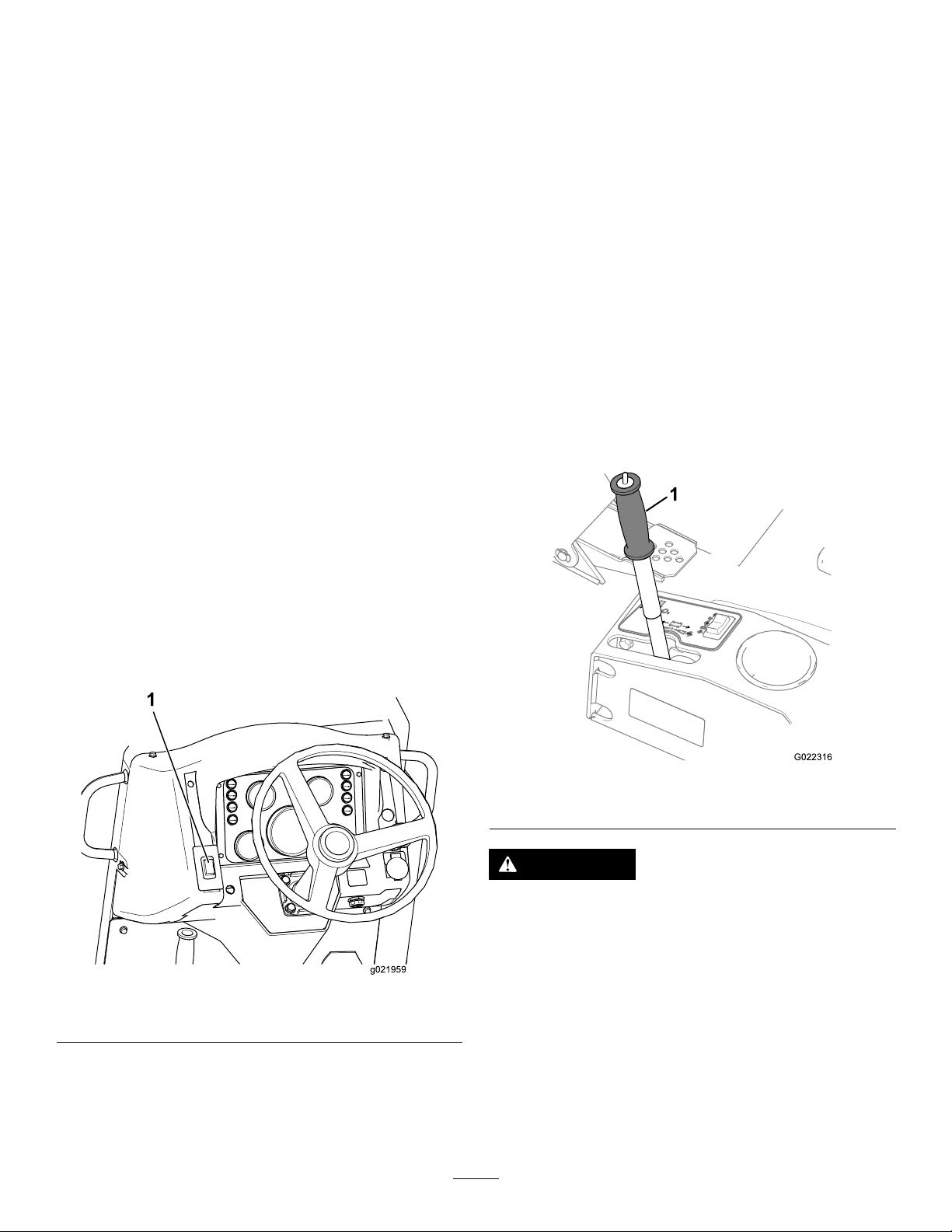
1.Pushtheparkingbrakeswitch(Figure23)uptoapply
theparkingbrake.
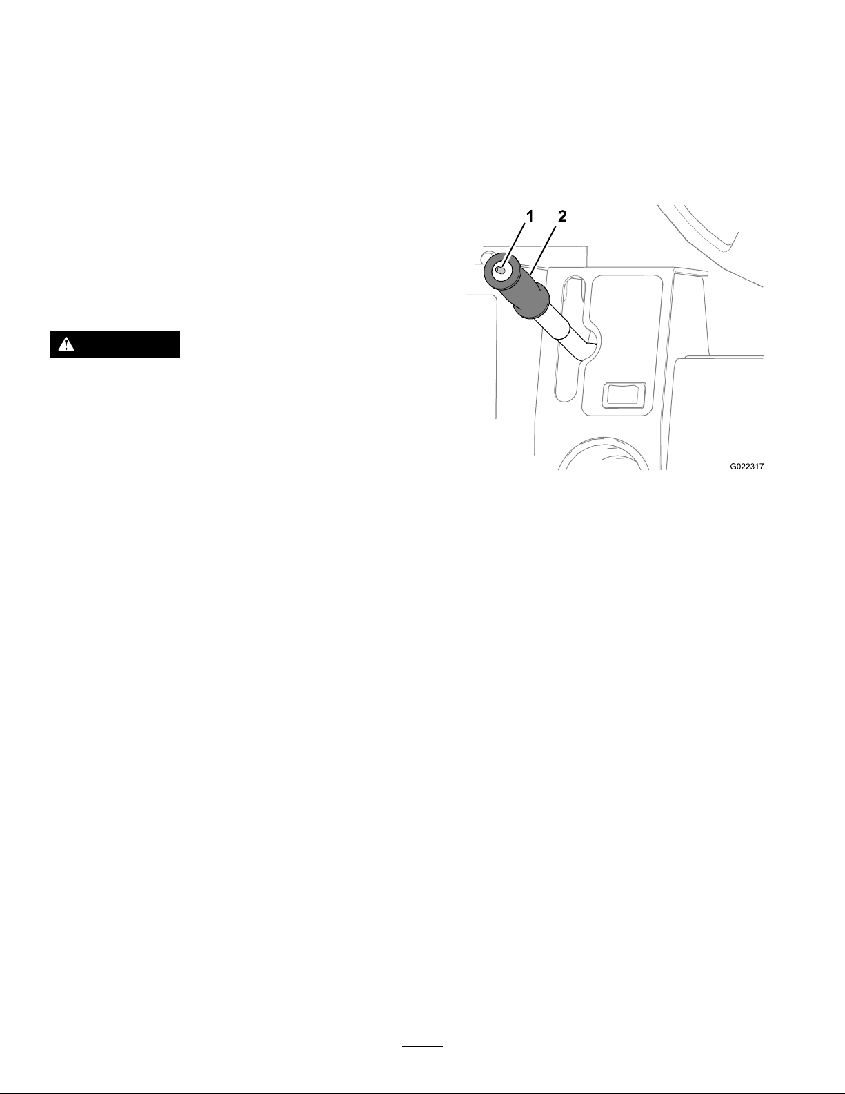
Thiscontrolleverallowsyoutonelyadjustthedirection
oftravelandthespeedofthemachineduringtrenching,
plowing,orboring.
Figure24
1.Utility-tractionlever
Figure23
1.Parkingbrake
2.Pushtheparkingswitchdowntoreleasetheparking
brake.
Note:Theparkingbrakeautomaticallyengageswhen
youstoptheengine.
WARNING
Toavoidinjury,remainintheoperatorseatto
operatethemachine.
Note:Ifyoudonotremainintheoperatorseat,theengine
willstopin1second.
1.Releasetheparkingbrake.
2.MovetheleveroutoftheNeutraldetentpositionand
tooneofthepositionsasfollows:
•Movetheleverforward(towardthefrontofthe
machine)tomovethemachineforward.
•Movetheleverrearward(towardtherearofthe
machine)tomovethemachineinreverse.
27
Page 28
Note:Movethelevercompletelyforwardorrearward
forthemaximumspeed.
OperatingtheTransmission
3.Releasethelever.
Note:Theleverisheldinplacefront-to-rearby
frictioninordertomaintainaconstantspeed.
4.ReturnthelevertotheNeutralpositiontostopthe
machine.
Note:Thegrounddrivefootcontroloverridesthe
tractionadjustmentcontrollever.Ifyouusethefoot
pedal,youmustmovethetractionadjustmentcontrol
levertotheNeutralpositiontoreleasetheoverrideand
returnthelevertonormaloperation.
StoppingtheMachine
WARNING
Jumpingonoroffthemachinecancauseaninjury.
Whenyougetonoroffthemachine,alwaysfacethe
machine,usethehandrailsandsteps,moveslowly.
Thismachinehashydrostaticbraking.Whenyouremove
yourfootfromthegrounddrivefootpedalormovethe
utility-tractioncontrolbacktoNeutral,themachinestops.
Alwaysapplytheparkingbrakeafteryoustopthemachine
andbeforeyoustoptheengine.
OperatingtheDriveModeSwitch
Thistoggleswitch(Figure25)controlsthemodeforthe
hydraulicmotorandhas2positions:TransportandWork.
Selectthedesiredoperatingposition.Pushtheswitchto
therear(towardyou)tosettoW orkspeed(W),orpushthe
switchforward(awayfromyou)tosettoTransportspeed(T).
Figure25
1.Drivemodeswitch2.Utility-tractionleverhandle
1.Movetolevelground,ifpossible.
Important:Ifyoumusttemporarilyparkthe
machineonaslopeoranincline,positionthe
machineatarightangletotheslope,withthe
frontofthemachinetowardthebottomofthehill.
Ensurethatthemachineisbehindanobjectthat
willnotmove.
2.Supportorlowerallattachmentstotheground.
3.Settheparkingbrake.
4.Tostoptheengine,refertoStoppingtheEngine(page
26).
5.Attheendoftheworkday,llthefueltankattheend
ofeachworkdaytopreventcondensationandmoisture
inthetank.
OperatingtheTransmissionRange
Switch
Thisrockerswitch(Figure26)alsohas2positions:Highand
Lowspeedranges.Theserangesareusedinconjunctionwith
thegroundspeedcontrol.
Presstheswitchtotheright(towardyou)forlowrange,or
presstheswitchtotheleft(awayfromyou)forhighrange.To
shiftthetransmission,stopthemachine(thetractioncontrol
pedalsandutility-controlleverintheNeutralposition)with
thecontrols-in-neutrallightilluminated.
Important:Thetransmissionwillnotshiftbetween
rangesunlessthemachinehasstoppedmoving.
28
Page 29
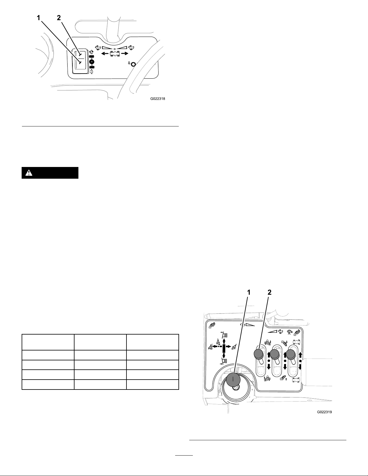
Figure26
1.Lowrange2.Highrange
•EnsurethattheROPSandtheseatbeltareproperly
installedandingoodworkingorder.
•Ensurethatallinstruments,thecontrols-in-neutrallight,
andtheallwarninglightsareworkingproperly .
•Ensurethatallcontrolsareworkingproperlyinaclear,
openarea.
Note:Thecontrols-in-neutrallightwillturnonwhenthe
keyswitchisintheOnpositionandtheutility-tractionlever
isintheNeutralposition.
1.Warmuptheengine.
2.PullthethrottleouttotheFullposition.
3.Raisetheequipmentandanyattachments(trencher,
plow,etc.).
Themachinehasa2-modehydrostaticdrivewitha2-range
transmissiontoprovide4forwardandreversespeeds.Select
thegearcombinationmostappropriatefortheoperationthat
youwillperform.
WARNING
Themachinecanrolluncontrolledifthetraction
controlsareintheNeutralposition.
Stopthemachineandsettheparkingbrakebefore
shiftingthetransmissioncontrol.
•Firstgear:WiththedrivemodeswitchintheW ork
position,pressthetransmissionrangeswitchtotheright
(nearyou)toselectthetransmissionintoLowrange.
•Secondgear:WiththedrivemodeswitchintheWork
position,pressthetransmissionrangeswitchtotheleft
(awayfromyou)toselectthetransmissionintoHigh
range.
•Thirdgear:WiththedrivemodeswitchintheTransport
position,pressthetransmissionrangeswitchtotheright
(nearyou)toselectthetransmissionintoLowrange.
•Fourthgear:Withthedrivemodeswitchinthe
Transportposition,pressthetransmissionrangeswitch
totheleft(awayfromyou)toselectthetransmissioninto
Highrange.
4.Releasetheparkingbrake.
Note:Youmustremainseatedintheoperatorseat
beforeyoumovetheengine;otherwise,theenginewill
stopin1second.
Note:Theutility-tractionlevercontrolsthespeedof
themachine.Thefartherthatyoumovetheleverfrom
theNeutralposition,thefasterthemachinemoves.
Important:Controlthespeedofthemachine
travelwiththeutility-tractionlever,notthethrottle.
5.Checktheindicatorlightsfrequently.
UsingtheBackllBlade
Important:Operatethecontrolsonlywhilesittingin
theoperatorseat.
Usethebackllbladetoreturnthespoilsintothetrench.
Youcontrolthebackllbladewithjoystickandthebackll
bladelevercontrolasshowninFigure27.
Gear
1stWorkLow
2ndWorkHigh
3rdTransportLow
4thTransportHigh
DriveModeTransmission
Range
PreparingtoOperatethe Machine
Afterstartingtheenginebutbeforeoperatingthemachineat
theworksite,dothefollowing:
Figure27
1.Joystick2.Tiltlever
29
Page 30
Tooperatethebackllblade,dothefollowing:
G023080
•Toraisethebackllblade:Movethejoystickrearward.
•Tolowerthebackllblade:Movethejoystickpartially
forward.
•Toanglethebackllbladetotheright:Movethejoystick
totheright.
•Toanglethebackllbladetotheleft:Movethejoystick
totheleft.
•Toholdthebackllblade:KeepthejoystickintheHold
(neutral)position.
•Tooatthebackllblade:Movethejoystickfullyforward.
•Totiltthebackllbladedownontheright:Movethetilt
leverright(awayfromyou).
•Totiltthebackllbladedownontheleft:Movethetilt
leverleft(towardyou).
Note:Forbestresultswhenbackllingthespoilswhile
paralleltothetrench,make2or3passesoverthespoilpile
withtheblade.
Note:Ifthespoilpileislarge,operatethemachineataright
angletothetrench.
TransportingtheMachine
Besurethatyouunderstandthesafetyrulesandlawsforthe
areainwhichyouareusingthemachine.Ensurethatboth
thetruckandthemachineareequippedwiththeproper
safetyequipment.
LoadingtheMachineontoaTrailer
1.Ensurethatthetrailerandtherampcansupportboth
yourweightandtheweightofthemachine.
2.Alwayshavetheattachmentsreadytotransportwhen
youareloadingorunloadingthemachine.
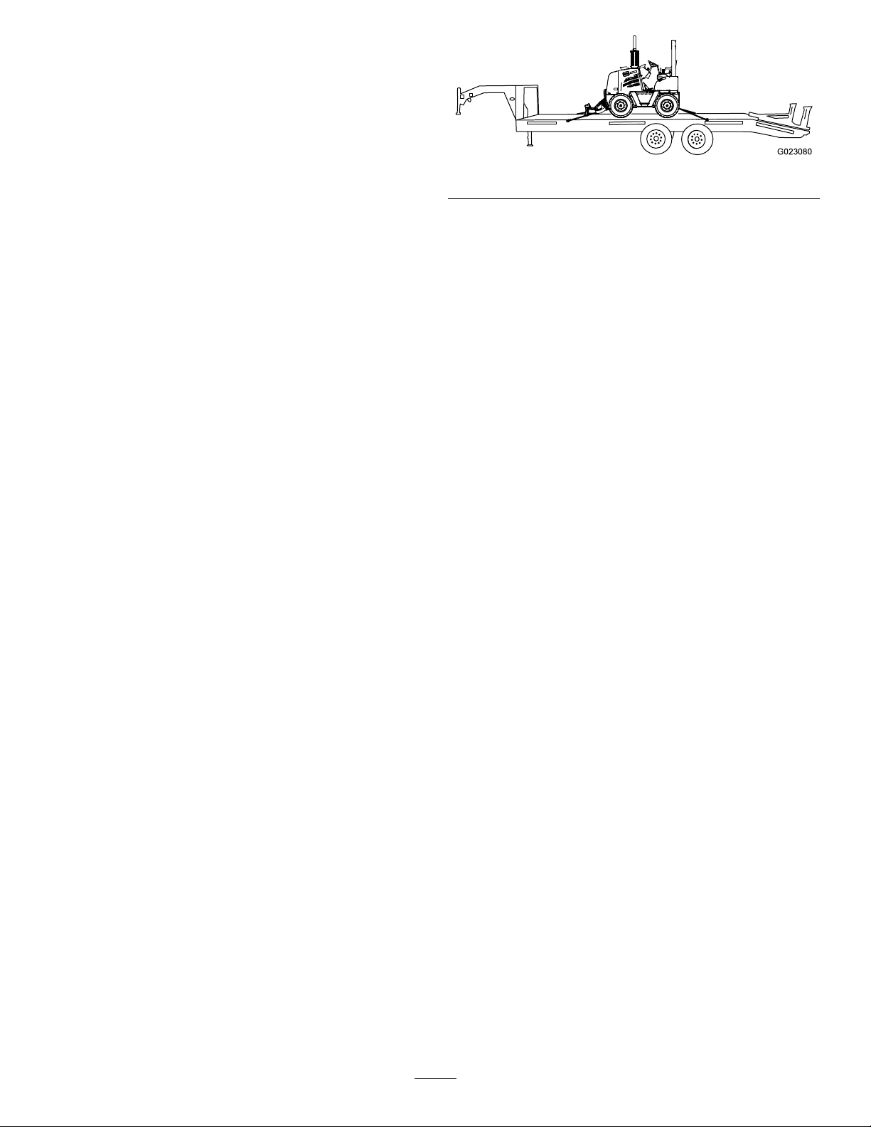
Figure28
10.Fastentherearofthemachinetothetrailerusing
chainsandabinder(Figure28).
Note:Usetherearaxletosecuretherearofthe
machine.
11.Measurethedistancefromthegroundtothehighest
pointofthemachine.
Note:Youmustknowtheclearanceheightofthe
machine.
12.Removetheblocksfromthefrontandreartrailer
wheels.
13.Afteryouhavedrivenafewmiles,stopthetruckand
checkyourload.
Note:Ensurethatthechainsarestilltightandthatthe
machinehasnotmovedonthetrailer.
UnloadingtheMachinefromaTrailer
1.Blockthefrontandreartrailerwheels.
2.Removetheblocksfromthefrontandrearwheelsof
themachine.
3.Removethestrapsfromthemachine.
4.Starttheengine.
5.EnsurethattheattachmentsareintheTransport
position.
6.Slowlymovethemachineoffthetrailer.
3.Blockthefrontandrearwheelsofthetrailer.
4.Slowlyandcarefullymovethemachineontothetrailer.
5.Lowertheattachmentstothetrailer.
6.Engagetheparkingbrake.
7.Stoptheengineandremovethekey.
8.Blockthefrontandrearwheelsofthemachine.
9.Fastenthefrontofthemachinetothetrailerusing
strapsandabinder(Figure28).
Note:Usethefrontaxletosecurethemachine.
LiftingtheMachinewithaSpreaderBar
1.Attachacraneliftcabletothesingle-liftpointofa
spreaderbar.
2.Attach2oftheliftcablesononeendofthespreader
bartoaliftingbarplacedundertherearofthemachine
frame.
3.Attachtheremaining2spreaderbarliftcablestoa
liftingbarplacedunderthefrontofthemachineframe.
4.Carefullyandslowlyliftthemachine,andloweritto
thedesiredlocation.
MovingaNon-functioningMachine
Repairanon-functioningmachineonthejobsite,ifpossible.
Otherwise,youmustdeterminewhetheryoucanmovethe
machinewithoutfurtherdamagingit.
30
Page 31
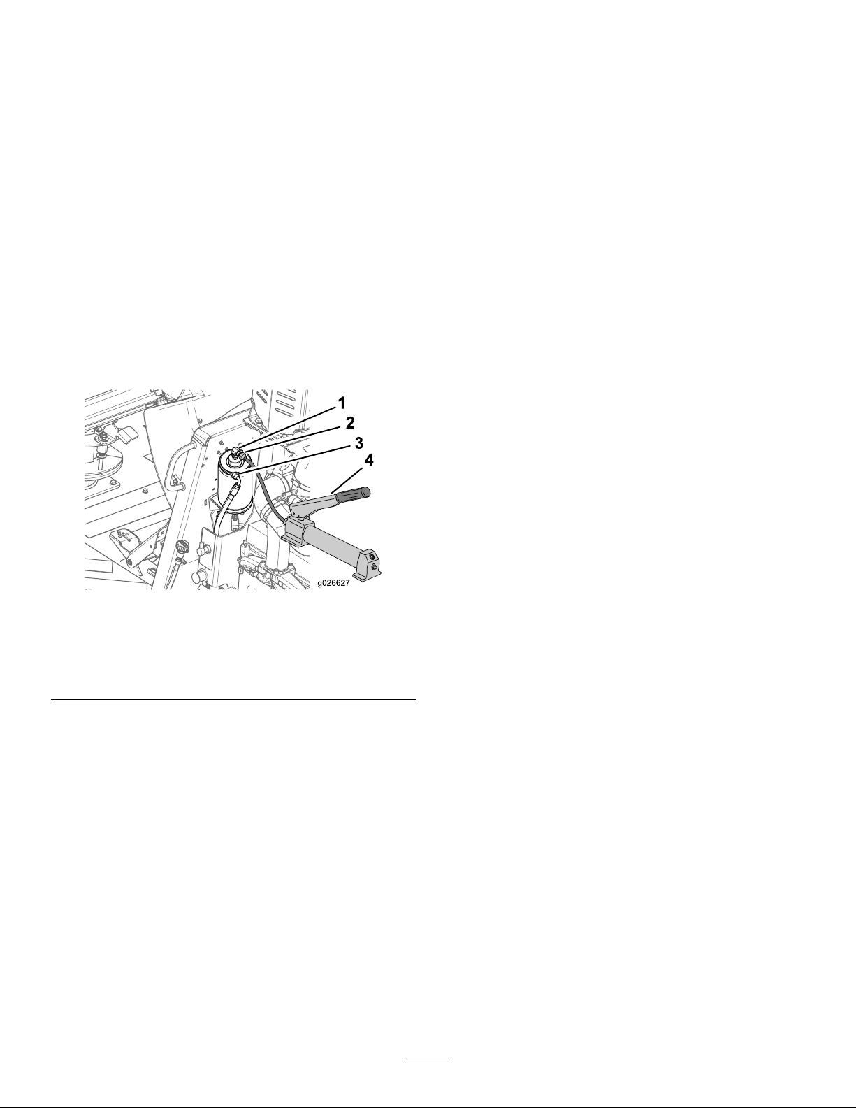
Ifyoumusttowthemachine,performthefollowingsteps
usingcaution:
Note:Ifyoudonothavearigiddrawbar,use2towing
machines.Attachatowchaineachtothefrontandrear
towingmachines.Usethefronttowingmachinetomovethe
non-functioningmachineandthereartowingmachineto
stopthenon-functioningmachine.
Note:Thismachinehashydrostaticbraking.Whenyoustop
theengine,thebrakesautomaticallyengage.
1.Disconnectthehydraulichosefromtheparkingbrake
cylinderasshowninFigure29.
CompletingtheWorkforthe Day
Whenyoucompleteyourworkfortheday,dothefollowing:
1.Backllthespoilsinthepart(s)ofthetrenchinwhich
youarenishedworking.
2.Movethemachinetoasafeandstablelocation.
3.MoveallleverstotheNeutralposition.
4.Engagetheparkingbrake.
5.Lowerallattachmentstotheground.
Note:Plugtheopenendofthehosetopreventthe
hydraulicuidfromleakingout.
Figure29
1.Parkingbrakecylinder
hydraulictting
2.Hydraulicbrakehose4.Handpump
2.Connectahydraulic-handpumpcapableofproducing
350psitothebrakecylinder(Figure29).
3.Operatethehandpumpuntilthebrakesarereleased.
4.Movetheutility-tractionlevertotheNeutralposition.
3.Handpumptting
connectedtothecylinder
tting
6.Letthemachineidleforafewmomentstocoolit
down.
7.Shutofftheengine,waitforallmovingparttostop,
andremovetheignitionkey.
8.TurnthebatterydisconnectswitchtotheDisconnect
position.
CompletingtheProject
1.Afteryoucompletetheproject,returnthespoilsback
intothetrenchwiththebackllblade;refertoUsing
theBackllBlade(page29).
2.Returnthespoilsintothetrench.
A.Movethemachinetotheendofthetrench,afew
feet(meters)awayfromthespoilpile.
B.Aimthemachineattheouteredgeofthepile.
C.Adjustthebackllbladetottheslopeofthe
ground.
D.Movetheouteredgeofthespoilpiletowardthe
trench.
Note:Makeatleast2passesatthepiletomove
it.
E.Repeatthestepsaboveforthespoilpileonthe
othersideofthetrench.
F.Floatthebackllbladeoverthelengthofthe
trench.
Note:Youcanmovethemachineupto8km/h(5
mph)andadistanceupto1.6km(1mile)away.To
transportadisabledmachinemorethan1.6km(1mile),
youmustuseasuitabletrailer;refertoTransportingthe
Machine(page30).
5.Towthemachinetothetransportvehicleortoasite
whereyoucanrepairthemachine.
6.Disconnectthehandpumpandconnectthehose
totheparkingbrakecylinderbeforetransportingor
makinganyrepairs.
3.Spraythedirtandmudoffthemachinewithwater.
Note:Donotspraytheconsoleorelectrical
componentswithwater.
4.Transportthemachinefromthecompletedworksite;
refertoTransportingtheMachine(page30).
31
Page 32

Maintenance
RecommendedMaintenanceSchedule(s)
MaintenanceService
Interval
Aftertherst100hours
Aftertherst200hours
Beforeeachuseordaily
Every50hours
Every200hours
Every250hours
MaintenanceProcedure
•Checktheoillevelinthewheelhubs.
•Checktheoillevelinthefrontandrearaxles.
•Checktheoillevelinthetransmission.
•Changethewheelhuboil.
•Changetheoilintheaxles.
•Changetheoilinthetransmissionandrearaxle.
•Checktheengineoillevel.
•Checkthehydraulicuidlevelinthereservoir.
•Greasethemachine.
•Checktheengineoillevel.
•Checktherestrictedair-cleanerlightforarestrictedaircleaner.
•Checkthetiresandwheelsfordamage.
•Checkthecoolantlevelinthereservoir.
•Checkandcleanthedustvalve.
•Checkthefuel-waterseparatorforwaterandsediment.
•Maintaintheproperairpressureinthetires.
•Checkthecoolantlevelintheradiator.
•Greasethefrontandrearaxles.
•Changetheengineoil.
•Changetheengineoillter.
•Checktheoillevelinthewheelhubs.
•Checktheoillevelinthefrontandrearaxles.
•Checktheoillevelinthetransmission.
•Checktheconditionoftheenginedrivebelt.
Every300hours
Every500hours
Every1,000hours
Every2,000hours
•Cleantheaxlebreatherforeachaxle.
•Checktheconditionofthecoolantsystemcomponents.Cleandirtanddebrisfrom
themandrepairorreplacethecomponentsasnecessary.
•Greasethedriveshaft.
•Replacethesecondaryfuellter.
•Replacetheprimaryfuellter.
•Changethehydraulic-pressurelter.
•Changethehydraulic-returnlter.
•CheckandmaintaintheROPS;checkitafteranaccident.
•Changethewheelhuboil.
•Changetheoilintheaxles.
•Changetheoilinthetransmissionandrearaxle.
•Checktheconcentrationofthecoolant.
•Checkthetensionontheenginedrivebelt.
•Changethehydraulicuidandcleanthebreather.
•Cleanthecoolingsystem.
32
Page 33
Premaintenance
Lubrication
Procedures
GreasingtheMachine
GeneralSafety
WARNING
Improperlyservicingorrepairingthemachinecan
causeinjuryordeath.
Ifyoudonotunderstandtheserviceproceduresfor
thismachine,contactanAuthorizedT oroService
Dealerortheservicemanualforthismachine.
WARNING
Raisedequipmentonthemachinewithoutan
operatorcancauseinjuryordeath.
Beforeyouleavetheoperatingarea,alwayssupport
orlowertheequipmenttothegroundandstopthe
engine.
WARNING
GreaseType:Lithium-basedgrease.
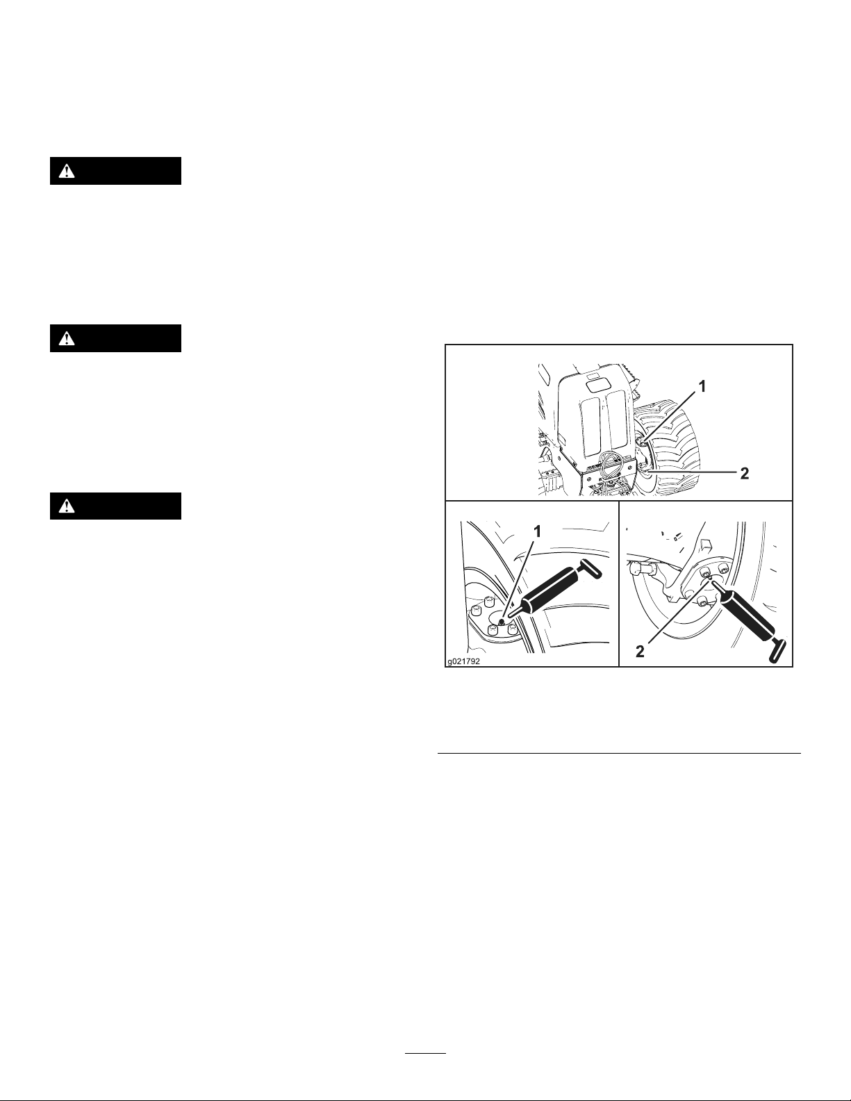
GreasingtheFrontandRearAxles
ServiceInterval:Every200hours
1.Cleanthegreasettingswitharag.
2.Connectthegreaseguntothegreasettingsforthe
upperandlowerpivots;apply2or3pumpsofgrease
toeachtting(Figure30andFigure31).
Note:Thereare2greasettingsattheaxlepivotfor
eachtire.
Replaceallcoversandguardsafteryouserviceor
cleanthemachine.Neveroperatethemachine
withoutthecoversorguardsinplace.
1.Parkthemachineonalevelsurface.
2.Lowerallattachmentsandstoptheengine,andremove
thekey.
3.Allowtheenginetocool2or3minutes.
4.Removetheright-sidepanel;refertoRemovingthe
SidePanels(page35).
5.Rotatethebattery-disconnectswitchtotheOff
position.
Figure30
Frontaxle
1.Greasetting(upperpivot)2.Greasetting(lowerpivot)
33
Page 34
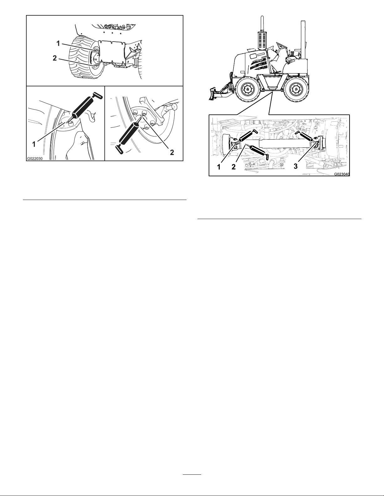
Figure31
Rearaxle
1.Greasetting(upperpivot)2.Greasetting(lowerpivot)
3.Wipeupanyexcessgrease.
1.Greasetting(forward
universaljoint)
2.Greasetting(slidingjoint)
Figure32
3.Greasetting(back
universaljoint)
GreasingtheDriveshaft
ServiceInterval:Every500hours
1.Cleanthegreasettingswitharag.
2.Connectthegreaseguntothegreasettingforthe
slidecouplingattheattheforwardendofthedrive
shaft,andapply2or3pumpsofgreasetothetting
(Figure32).
3.Connectthegreaseguntothegreasettingforthe
universaljointattheforwardendofthedriveshaft,
andapply2or3pumpsofgreasetothetting.
4.Connectthegreaseguntothegreasettingforthe
universaljointatthebackendofthedriveshaft,and
apply2or3pumpsofgreasetothetting.
5.Wipeupanyexcessgrease.
GreasingtheBackllBlade
ServiceInterval:Beforeeachuseordaily
1.Cleanthegreasettingswitharag.
2.Connectthegreaseguntotheupperandlowergrease
ttingsfortheliftcylinder,andapply3pumpsof
greasetoeachtting(Figure33).
34
Page 35
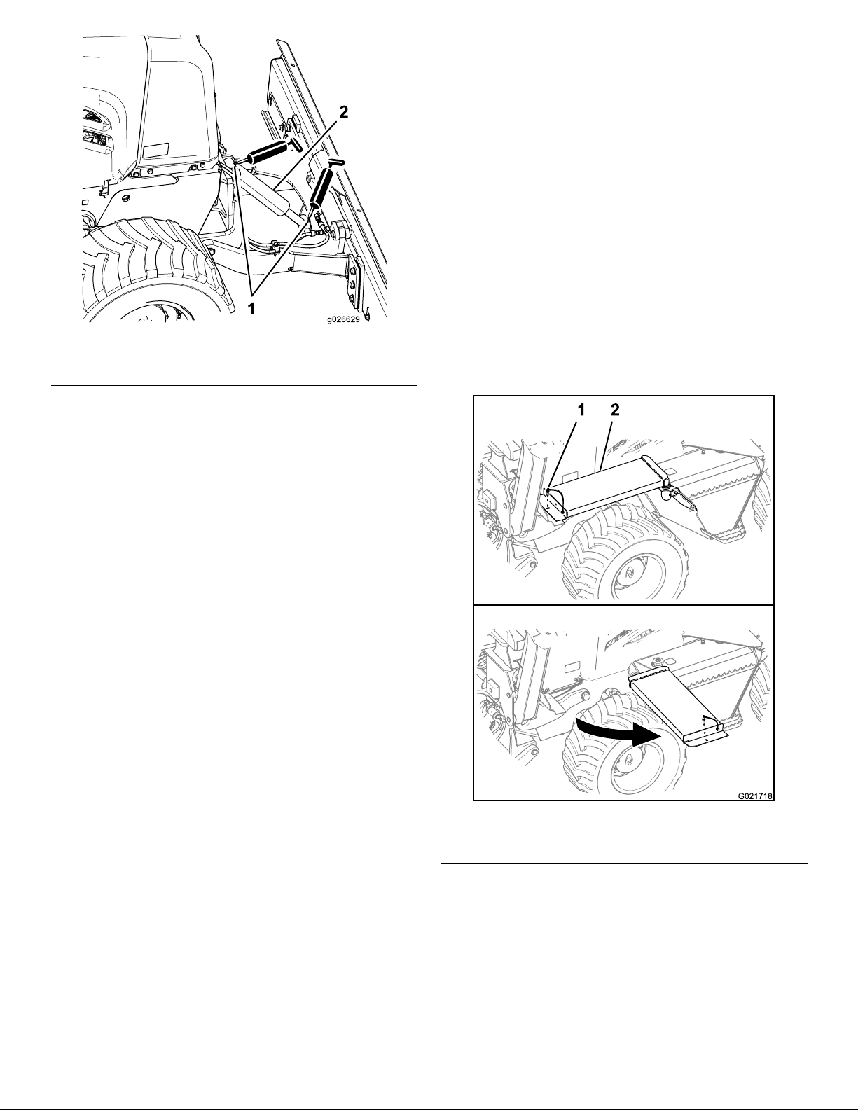
Figure33
1.Greasettings2.Liftcylinder
3.Wipeupanyexcessgrease.
EngineMaintenance
Beforemaintainingtheengine,performthefollowingsteps:
1.Parkthemachineonlevelground,lowerall
attachments,andstoptheengine.
2.Removetheignitionkeyandallowtheenginetocool
for2or3minutes.
AccessingtheEngine
RemovingtheSidePanels
1.Iftheoptionalbackhoeisinstalled,performthe
followingsubstepstoremovetheleftsidepanel;
otherwise,skiptostep2:
A.Attheleftsideofthemachine,removethe
retainingpinfromthefrontendofthewalkway
(Figure34).
Figure34
1.Retainingpin2.Walkway
B.Pivotthewalkwayawayfromthemachineas
showninFigure34.
2.Pulluponthehandgripofthepanellatch,andswing
thelatchfreefromtheanchorbracket(Figure35).
35
Page 36
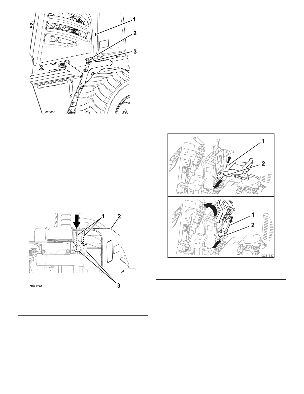
Figure35
1.Sidepanel
2.Panellatch
3.Anchorbracket
3.Liftthesidepanelstraightupandremoveitfromthe
machine(Figure35).
6.Ifthebackhoeisinstalledonthemachine,dothe
followingsubsteps:
A.Rotatethefrontendofthewalkwaytoitsoriginal
position(Figure34).
B.Aligntheholeinthewalkwaywiththeholeinthe
walkwaysupportbracket(Figure34).
C.Installtheretainingpinthroughtheholes.
RemovingtheNosePanel
1.Removeboththeleftsidepanelandtherightside
panelfromthemachine;refertoRemovingtheSide
Panels(page35).
2.Ifthebackhoeisinstalledonthemachine,dothe
followingsubsteps;otherwise,skiptostep3.
A.Removethehairpinfromtheseatlockpin(Figure
37).
InstallingtheSidePanels
1.Aligntheleftsidepanelwiththeleftsideofthe
machineandtherightsidepanelwiththerightside
ofthemachine.
2.Alignthetabsatthetopofthesidepanelwiththe
receiverbracketsonthemachine(Figure36).
Figure36
1.Tab3.Receiverbrackets
2.Sidepanel
3.Lowerthesidepanelstraightdown.
Note:Ensurethatthetabsofthesidepanelaligninto
thereceiverbracketsonthemachine.
4.Pullthehandgripofthepanellatchoutward,thenpivot
itupuntilitalignsintheanchorbracket(Figure35).
Figure37
1.Hairpin
2.Seatlockpin
B.Removetheseatlockpinfromtheframeofthe
backhoeandtheseatpost(Figure37).
C.Pivottheseatpostupward,andinsertthe
seat-lockpinthroughtheholesintheframeof
thebackhoetoholdtheseatuptomakeroomfor
removingthenosepanel(Figure37).
Note:Installtheseatlockpinandhairpininthe
backhoeframetoholdtheseatupposition.
3.Removethe4boltsatthebottomoftheleftandright
sidesofthenosepanel(Figure38).
5.Releasethelatchhandle.
36
Page 37
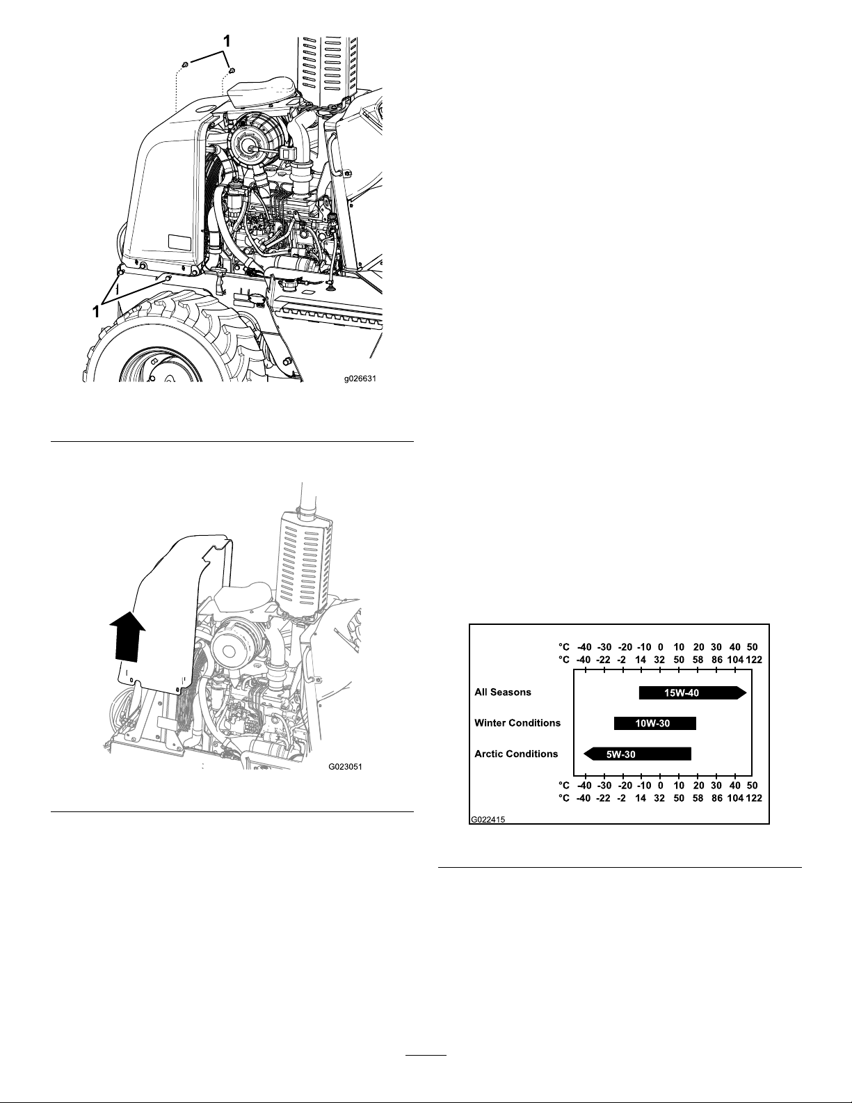
Note:Whenyouinstallthenosepanelfromthe
°C°C-40
-30 -20 -10 0 10 20 30 40 50
-40 -22 -2 14 32 50 58 86 104 122
All Seasons
Winter Conditions
Arctic Conditions
°C°C-40
-30 -20 -10 0 10 20 30 40 50
-40 -22 -2 14 32 50 58 86 104 122
15W -40
10W -30
5W-30
G022415
machinewhentheoptionalbackhoeisattached,gently
pushthehosesinthefrontofthenosepanelforward
whileloweringthepanelintoplace.
3.Securethenosepaneltothemachinewiththe4bolts
thatyouremovedduringstep3ofInstallingtheNose
Panel(page37).
4.Ifthebackhoeisinstalledonthemachine,dothe
followingsubsteps:
A.Removetheseatlockpinandlowertheseatpost
totheoperatingposition(Figure37).
B.Installtheseatlockpinthroughtheholesinthe
frameofthebackhoeandtheseatpost(Figure
37).
C.Installthehairpinintotheholeintheseatlock
pin(Figure37).
5.Installtheleftandrightsidepanelsonthemachine;
refertoInstallingtheSidePanels(page36).
Figure38
1.Bolts
ServicingtheEngineOiland Filter
4.Liftthenosepanelupandoffthemachine(Figure39).
InstallingtheNosePanel
1.Alignthenosepanelovertheradiatorofthemachine.
2.Lowerthenosepaneldownandontothemachine
Figure39
Note:Whenyouremovethenosepanelfromthe
machinewhentheoptionalbackhoeisattached,gently
pushthehosesinthefrontofthenosepanelforward
whileliftingthenosepanelupward.
(Figure39).
Theengineisshippedwithoilinthecrankcase;however,
checktheoillevelbeforeandafteryourststarttheengine.
Thecrankcasecapacityis11.0L(11.6USqt)withthelter.
Useonlyhigh-qualitySAE15W -40heavy-dutyengineoilwith
anAPIclassicationofCH-4orhigher.
WhileSAE15W-40oilwithanAPIclassicationofCH-4or
higherisrecommendedformostclimates,refertoFigure40
foroilviscosityrecommendationsforextremeclimates.
Figure40
Note:Limiteduseoflow-viscosityoilssuchasSAE10W-30
withanAPIclassicationofCH-4orhighercanbeusedfor
easierstartingandprovidingsufcientoilowatambient
temperaturesbelow-5°C(23°F).However,continuoususeof
lowviscosityoilcandecreaseenginelifebecauseofwear.
ToroPremiumEngineOilisavailablefromanAuthorized
ToroServiceDealerineither15W -40or10W-30viscosity
withAPIclassicationCH-4orhigher.SeethePartsCatalog
37
Page 38
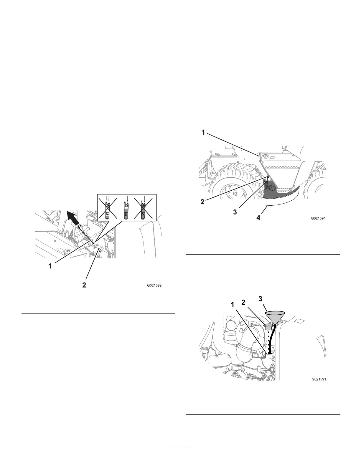
forpartnumbers.Also,refertotheEngineOperator'sManual,
includedwiththemachine,forfurtherrecommendations.
ChangingtheEngineOil
ServiceInterval:Every250hours
CheckingtheEngineOilLevel
ServiceInterval:Beforeeachuseordaily
Note:Thebesttimetochecktheengineoiliswhenthe
engineiscoolbeforeithasbeenstartedfortheday,if
possible.IftheoillevelisatorbelowtheAddmarkonthe
dipstick,addoiltotheenginetobringtheoilleveluptothe
Fullmark.Donotoverll.IftheoillevelisbetweentheFull
andAddmarksonthedipstick,youdonotneedtoaddoil.
1.Ensurethatthemachineisonalevelsurface.
2.Lowerallattachments,settheparkingbrake,stopthe
engine,andremovethekey.
Note:Ifyouhaveruntheengine,allowatleast10
minutesfortheengineoiltosettleinthecrankcase.
3.Removetherightsidepanel;refertoRemovingthe
SidePanels(page35).
4.Removethedipstickandwipecleanitwithaclean
cloth(Figure41).
DrainingtheEngineOil
1.Runtheengineafewminutesbeforechangingtheoil
towarmit.
Note:Warmoilowsbetterandcarriesmore
contaminants.
2.Removetherightsidepanel;refertoRemovingthe
SidePanels(page35).
3.Placeadrainpanthathasaminimumcapacityof8.4
L(8.9USqt)undertheengine-oildraintting(Figure
42).
Figure41
1.Dipstick2.Dipsticktube
5.Insertthedipstickintothedipsticktube,pullthe
dipstickoutagain,andreadtheoillevelonthedipstick
(Figure41).
Note:Theoillevelonthedipstickshouldbebetween
theH(high)markandL(low)mark.
6.IftheoillevelisbelowtheL(low)mark,removethe
llcapandaddoiluntilthelevelreachestheH(high)
mark.
Important:Donotoverlltheenginewithoil.
7.Installthedipstick.
8.Installtherightsidepanel;refertoInstallingtheSide
Panels(page36).
Figure42
1.Engine-oiltank
2.Draintting
3.Cap
4.Drainpan
4.Removethecapfromthedrainttingandallowthe
engineoiltodraincompletely(Figure42).
Note:Removingtheoil-llcapfromthellerneck
helpstodraintheengineoil(Figure43).
Figure43
1.Fillerneck3.Funnel
2.Oil-llcap
5.Cleanthematingsurfacesofthecapandthedrain
tting.
38
Page 39
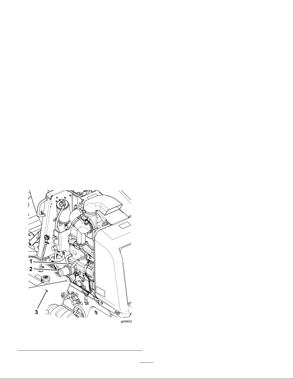
6.Installthecapontothedraintting(Figure42).
FillingtheEnginewithOil
1.Removetheoil-llcapfromthellerneckbypulling
thecapupward(Figure42).
Note:Useafunnelwithaexiblehosetodirectthe
engineoilintotheengine.
2.Fillthecrankcasewithapproximately7.0L(7.4US
qt)ofthespeciedengineoil;refertoServicingthe
EngineOilandFilter(page37).
3.Installtheoil-llcap.
4.Starttheengine,runitatidleforabout2minutes,and
checkforoilleaks.
5.Stoptheengineandremovethekey.
6.Waitfor2or3minutesandchecktheoillevel;referto
steps2through6inCheckingtheEngineOilLevel
(page23).
7.Installthesidepanel;refertoInstallingtheSidePanels
(page36).
ChangingtheEngineOilFilter
ServiceInterval:Every250hours
1.Removetherightsidepanel;refertoRemovingthe
SidePanels(page35).
2.Placeasmalldrainpanundertheoillterandthe
oil-lteradapter(Figure44).
3.Rotatetheoilltercounterclockwiseandremovethe
oillter(Figure44).
Note:Recycletheusedoillteraccordingtolocal
codes.
4.Useacleanragtowipecleanthesurfaceoftheoil
cooler,wheretheoillterseats.
5.Fillthenewoillterwiththespeciedengineoil,allow
thelterelementtosaturatewiththeoil,andthenpour
outtheexcessoil.
6.Applyathinlayeroftheengineoiltothesealofthe
newoillter.
7.Alignthenewoilltertotheoil-lteradapterand
rotatethelterclockwiseuntilthesealoftheoillter
contactstheoilcooler(Figure44).
Note:Donotuseanoillterwrenchtoinstallthe
newoillter.Thewrenchcandentanoillter,causing
aleak.
8.Handtightentheoillteranadditional1/2turn
(Figure44).
9.Removethesmalloilpanfromundertheoillter.
10.Checktheengineoillevel;refertoCheckingtheEngine
OilLevel(page38).
11.Installthesidepanel;refertoInstallingtheSidePanels
(page36).
Figure44
ServicingtheAir-cleaner System
Important:Donotremovetheelementsfromthe
machinetocheckforarestriction;alwaysfollowthe
instructionsinthefollowingprocedures.
Note:Donotreplaceanoldaircleanerelementwithan
elementthatismorethan5yearsold;checkthedateof
manufactureontheendcapoftheelement.
Note:Everytimeyouservicetheaircleanersystem,ensure
thatallhoseconnectionsandangesareairtight.Replace
alldamagedparts.
ServicingtheDustValve
ServiceInterval:Every50hours
Squeezethesidesofthedustvalvetoreleaseanycollected
water,dust,ordirtfromthevalve(Figure45).
Note:Ensurethattherearenoobstructionsinsidethedust
valve.
1.Oilcooler3.Hydraulic-uidtank
2.Oillter
39
Page 40
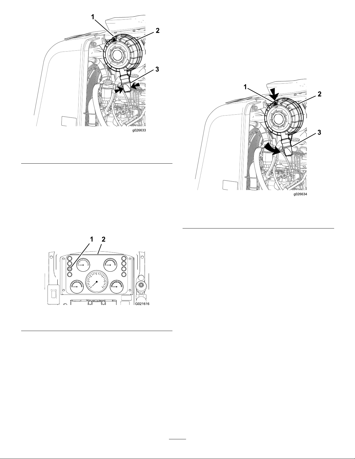
Figure45
1.Latch3.Dustvalve
2.Air-cleanercover
CheckingtheRestrictedAir-cleaner
Light
RemovingtheAir-cleanerCover
1.Removetheleftsidepanel;refertoRemovingtheSide
Panels(page35).
2.Pullthelatchfortheair-cleanercoveroutward(Figure
45).
3.Rotatethecleanercovercounterclockwisesothatthe
dustcapisatthe7o’clockposition(Figure47).
ServiceInterval:Beforeeachuseordaily
1.Starttheengine;refertoStartingtheEngine(page25).
2.Checktherestrictedair-cleanerlightontheinstrument
cluster(Figure46).
Figure46
1.Restrictedair-cleanerlight2.Instrumentcluster
3.Replacetheair-cleanerelement(s)asfollows:
A.Replacetheprimaryair-cleanerelement;referto
ReplacingthePrimaryElement(page41).
B.Repeatsteps1and2.
Figure47
1.Latch3.Dustcap
2.Air-cleanercover
4.Pulltheair-cleanercoverawayfromthecleanerhousing
toremovethecover.
5.Cleantheinsideofthecoverwithacleandampcloth.
C.Iftherestrictedair-cleanerlightstillcomeson,
replacethesecondaryair-cleanerelement;referto
ReplacingtheSecondaryElement(page41).
40
Page 41
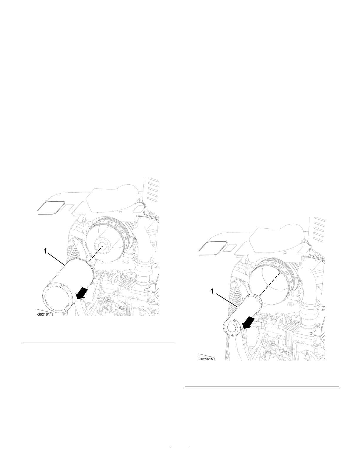
InstallingtheAir-cleanerCover
1.Alignthedustcapontheair-cleanercovertothe7
o’clockposition.
2.Aligntheair-cleanercoverontothecleanerhousing.
3.Rotatetheair-cleanercoverclockwisesothatthedust
capisatthe8o’clockposition(Figure45).
4.Pushthelatchfortheair-cleanercoverinwarduntilthe
coverisfullyseated(Figure45).
6.Insertthenewprimaryair-cleanerelementintothe
air-cleanerhousing(Figure48).
Note:Ensurethattheair-cleanerelementisfully
seatedinthehousing.
7.Installtheair-cleanercover;refertoInstallingthe
Air-cleanerCover(page41).
8.Checktherestrictedair-cleanerlight;refertoChecking
theRestrictedAir-cleanerLight(page40).
5.Installtheleftsidepanel;refertoInstallingtheSide
Panels(page36).
ReplacingthePrimaryElement
Important:Replacetheprimaryair-cleanerelement
whentherestrictedair-cleanerlightcomeson.
1.Removetheair-cleanercover;refertoRemovingthe
Air-cleanerCover(page40).
2.Pulltheprimaryair-cleanerelementoutwardand
removeitfromtheair-cleanerhousing(Figure48).
ReplacingtheSecondaryElement
Note:Replacethesecondaryair-cleanerelementafteryou
havereplacedtheprimaryair-cleanerelement3timesorif
theair-cleanerrestrictionlightcomesonwhiletheengineis
runningandyouhavealreadyreplacedprimaryair-cleaner
element.
Important:Donotcleaneithertheprimaryelement
orthesecondaryelement.
1.Removetheair-cleanercover;refertoRemovingthe
Air-cleanerCover(page40).
2.Pulltheprimaryair-cleanerelementoutwardand
removeitfromtheair-cleanerhousing;referto
ReplacingthePrimaryElement(page41).
Pullthesecondaryair-cleanerelementoutwardand
removeitfromtheair-cleanerhousing.(Figure49).
Figure48
1.Primaryair-cleanerelement
Note:Discardtheoldair-cleanerelement.
3.Useacleandampclothtocleantheinsideofthe
cleanerhousing.
4.Usealighttoinspectthenewelementfordamage;if
theelementisdamaged,replaceit.
Note:Checkthedateofmanufactureontheendof
thenewair-cleanerelement.Donotinstallanelement
thatismorethan5yearsold.
5.Writethecurrentdateandtheenginehoursontheend
oftheelementwithapermanentmarkingpen.
Figure49
1.Secondaryair-cleanerelement
Note:Discardtheoldair-cleanerelement.
3.Cleantheinsideofthecleanerhousingwithaclean,
dampcloth.
4.Insertthenewsecondaryair-cleanerelementintothe
air-cleanerhousing(Figure49).
41
Page 42
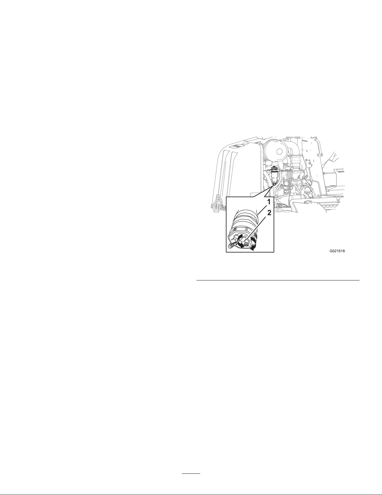
Note:Ensurethatthesecondaryelementisfully
seatedinthehousing.
FuelSystem
5.Inserttheprimaryair-cleanerelementintotheair-lter
housing;refertoReplacingthePrimaryElement(page
41).
Note:Ensurethattheprimaryelementisfullyseated
inthehousing.
6.Installtheair-cleanercover;refertoInstallingthe
Air-cleanerCover(page41).
7.Checktherestrictedair-cleanerlight;refertoChecking
theRestrictedAir-cleanerLight(page40).
Maintenance
ServicingtheFuelSystem
DrainingtheFuel-waterSeparator
ServiceInterval:Every50hours
1.Removetheleftsidepanel;refertoRemovingtheSide
Panels(page35).
2.Placeasmalldrainpanunderthesecondaryfuellter
(Figure50).
Figure50
1.Secondary-fuellter
3.Rotatethedrainvalveatthebottomofthesecondary
fuellter2or3turnscounterclockwise,anddrainany
waterandsedimentfromthefuel-waterseparatorof
thefuellter(Figure50).
Note:Ifthefuel-waterseparatorhasanywateror
sediment,drainthewaterandsedimentfromthefuel
tank;gotostep2.
4.Whencleanfuelappears,rotatethedrainvalve
clockwiseuntilitisclosed(Figure50).
Note:Donotovertightenthedrainvalve.
5.Bleedthefuelsystem;refertoBleedingtheFuelSystem
(page44).
6.Installtheleftsidepanel;refertoInstallingtheSide
Panels(page36).
2.Drainvalve
DrainingWaterfromtheFuelTank
1.Placeadrainpanunderthedrainpluginthefueltank.
2.Unscrewthedrainplugfromthefueltankanddrain
thewater(Figure51).
42
Page 43
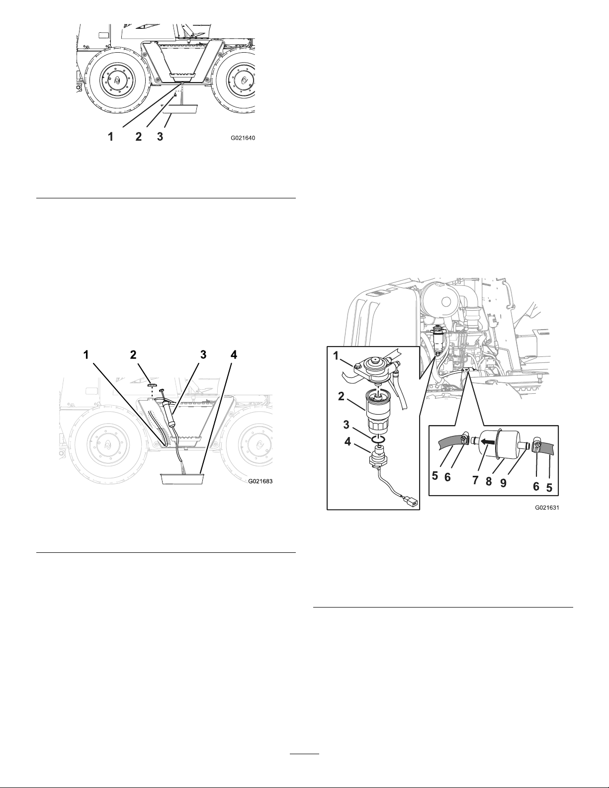
Figure51
1.Fueltank3.Drainpan
2.Drainplug
ReplacingtheFuelFilters
ReplacingtheSecondaryFuelFilter
ServiceInterval:Every500hours
1.Removetheleftsidepanel;refertoRemovingtheSide
Panels(page35).
2.Removethesecondaryfuellterandfuel-water
separatorasfollows:
A.Cleanthesecondaryfuellterandthesurrounding
area.
B.Completelydrainthefuel-waterseparator;referto
DrainingtheFuel-waterSeparator(page42).
3.Whencleanfuelappears,installthedrainplugand
tightenitsecurely(Figure51).
4.Checkthefueltankdrainplugforleaks.
SiphoningWaterfromtheFuelTank
Note:Siphoningwaterfromthefueltankisanalternative
todrainingwaterfromthefueltank;refertoDrainingW ater
fromtheFuelTank(page42).
1.Removethefuelcapfromthefueltank(Figure52).
Figure52
C.Firmlygraspthesecondaryfuel-lterelement,
rotatethewatersensorcounterclockwise,and
removethewatersensor(Figure53).
Note:Retainthewatersensor,butdiscardthe
O-ring.
1.Intakehose(bottomofthe
tank)
2.Fuelcap4.Drainpan
3.Siphoningequipment
2.Routetheintakehoseofthesiphoningequipment
throughthellerneckofthefueltankandtothe
bottomofthetank(Figure52).
3.Directthedischargehoseofthesiphoningequipment
intoadrainpan(Figure52).
4.Siphonthetankuntilcleanfuelappears.
5.Removethesiphoningequipmentfromthetank.
6.Installthefuelcapontothellerneckofthefueltank
(Figure52).
Figure53
1.Filteradapter6.Hoseclamp
2.Secondarylterelement
3.O-ring8.Primaryfuellter
4.Watersensor9.Fitting
5.Fuelhose
7.Arrow
D.Firmlygraspthesecondaryfuel-lterelement,
rotateitcounterclockwise,andremoveitfromthe
lteradapter(Figure53).
Note:Discardthelterelement.
E.Cleanthelteradapterwithacleanrag.
Important:Donotusealterwrenchto
tightenthelter.Youcoulddamagethelter
andcausealeak.
43
Page 44
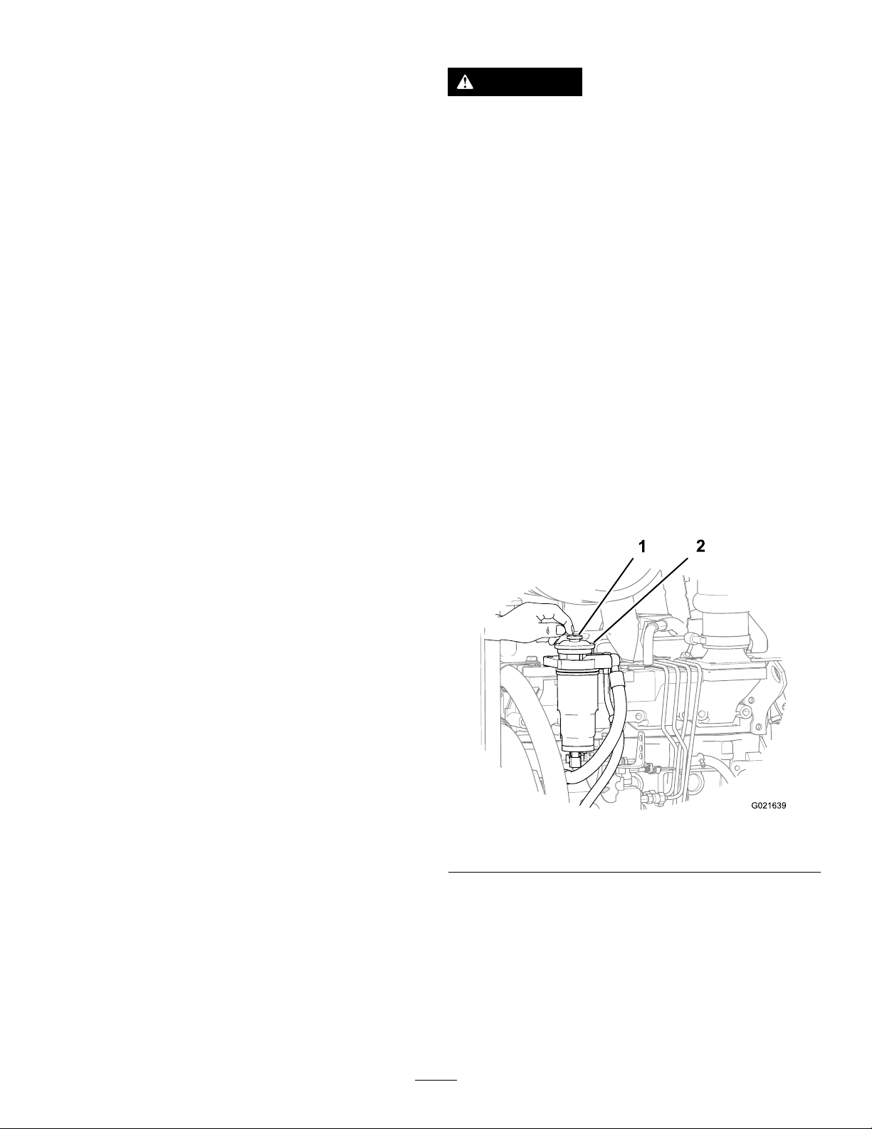
3.Installthesecondaryfuellterandfuel-waterseparator
asfollows:
A.Applyathinlmofcleanfueltothesealonthe
fuel-lterelement.
B.Alignthenewsecondarylterelementtothelter
adapter(Figure53).
C.Rotatethesecondarylterelementuntiltheseal
contactsthelteradapter,thenrotatethelter
elementanadditional3/4turn.
D.SlipthenewO-ringoverthewatersensor(Figure
53).
E.Alignthewatersensortothebottomofthe
secondaryfuellter(Figure53).
F.Firmlygraspthesecondarylterelement,and
rotatethewatersensorclockwiseuntilitishand
tight(Figure53).
4.Bleedthefuelsystem;refertoBleedingtheFuelSystem
(page44).
5.Starttheengineandcheckforleaksatthefuellter.
6.Installtheleftsidepanel;refertoInstallingtheSide
Panels(page36).
BleedingtheFuelSystem
WARNING
Thefuelsystemisunderhighpressure.Bleeding
thesystemwithoutproperprecautionsandtraining
couldresultininjurytoyoufrominjecteduidor
reorexplosion.
ReadtheEngineOwner’sManualfortheproper
bleedingprocedureorcontactyourAuthorizedToro
ServiceDealer.
Note:Removeairfromthefuelsystemwheneveryoudoany
ofthefollowing:
•Drainthefuel-waterseparator
•Replacethefuellter
•Runtheengineuntilthefueltankisempty
1.Ensurethatboththeengineandtheexhaustsystem
arecool.
2.Ensurethatthefueltankis1/4full.
3.Rotatethebattery-disconnectswitchclockwisetothe
Onposition.
ReplacingthePrimaryFuelFilter
ServiceInterval:Every500hours
1.Removetheleftsidepanel;refertoRemovingtheSide
Panels(page35).
2.Placecleanragsundertheprimaryfuellter.
3.Loosenthehoseclampsandseparatetheprimaryfuel
lterfromthefuelhoses(Figure53).
Note:Donotremovethehoseclampsfromthehoses.
Note:Discardthefuellter.
4.Alignthenewprimaryfuelltertothehoseswiththe
arrowprintedonthelterpointingforward(Figure53).
5.Slipthehosesoverthehosettingoftheprimaryfuel
lter,andtightenthehoseclamps(Figure53).
6.Bleedthefuelsystem;refertoBleedingtheFuelSystem
(page44).
7.Starttheengineandcheckforleaksatthefuellter.
8.Installtheleftsidepanel;refertoInstallingtheSide
Panels(page36).
4.Locatetheprimingbuttononthetopofthelter
adapterforthesecondaryfuellter(Figure54).
Figure54
1.Primingbutton2.Filteradapter
5.Pressdownandreleasetheprimingbuttonrepeatedly
untilyoufeelresistance(Figure54).
6.Starttheengine;refertoStartingtheEngine(page25).
Note:Iftheenginedoesnotstartafterprimingthe
fuelsystemandmakingseveralattemptstostartthe
engine,bleedthehigh-pressurefuellines;refertoyour
engineowner’ smanualorcontactyourAuthorized
ToroServiceDealerforassistance.
44
Page 45
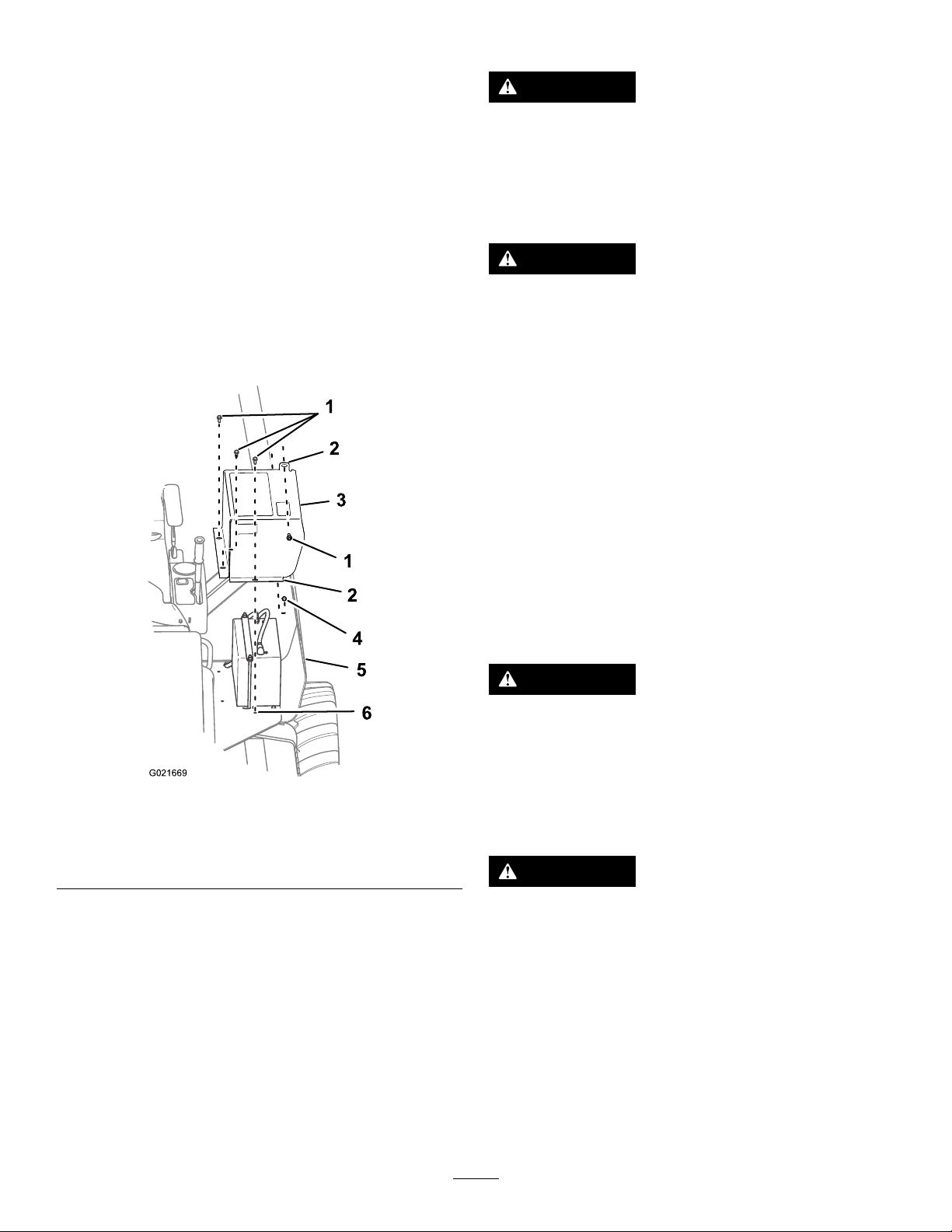
ElectricalSystem
G021669
1
5
2
3
1
2
4
6
ServicingtheBattery
Maintenance
MaintainingtheBattery
AccessingtheBattery
Removethebatterycoverasfollows:
1.Ensurethatthebattery-disconnectswitchisintheOff
position;refertoBattery-disconnectSwitch(page21).
2.Removetheboltthatsecuresthebatterycovertothe
ROPSplate(Figure55).
Note:Thebatterycoverislocatedbetweenthe
utility-tractioncontrolandtheleftfender.
WARNING
Exposuretobatteryacidorabatteryexplosioncan
causeseriouspersonalinjury.
Beforeyouserviceabattery,alwayswearface
protection,protectivegloves,andprotective
clothing.
WARNING
Abatterycontainssulfuricacid,whichcancause
seriousburns;andtheycanproduceexplosive
gases.
•Avoidcontactwithskin,eyes,orclothing;ush
affectedareaswithwater.
•Iftakeninternally,drinklargequantitiesofwater
ormilk.
Do not
attentionimmediately.
•Keepsparks,ames,andlitcigarettesandcigars
awayfromthebattery .
•Ventilatethebatterywhenyouarechargingitor
usingitinanenclosedarea.
•Weareyeprotectionwhenworkingneara
battery.
•Washyourhandsafterhandlingabattery.
•Keepthebatteryoutofthereachofchildren.
inducevomiting.Seekmedical
Figure55
1.Bolts
2.Flange5.Fender
3.Batterycover
3.Removethe3boltsthatsecurethebatterycoverto
theoperatorplatform,andremovethebatterycover
(Figure55).
Installthebatterycoverasfollows:
1.Aligntheholesinthemountingangesforthebattery
coverwiththeholesintheoperatorplatformaround
thebattery(Figure55).
2.SecurethebatterycovertotheROPSplatewithabolt
(Figure55).
3.Securethebatterycovertotheoperatorplatformwith
the3boltsthatyoupreviouslyremoved(Figure55).
4.ROPSplate
6.Operatorplatform
WARNING
Afrozenbatterycanbeexplosive,causingpersonal
injurytoyouorothersinthearea,ifyoutryto
chargethebatteryortrytojumpstartthebattery
andruntheengine.
Topreventthebatteryelectrolytefromfreezing,
keepthebatteryfullycharged.
WARNING
Sparksoraamecancausehydrogengasina
batterytoexplode.
Whenyoudisconnectthebatterycables,always
disconnectthenegative(-)cablerst.
Whenyouconnectthebatterycables,always
connectthenegative(-)cablelast.
Donotshort-circuitthebatterypostswithametal
object.
Donotweld,grind,orsmokenearabattery.
Note:Theelectricalsysteminthismachineis12volts.
45
Page 46
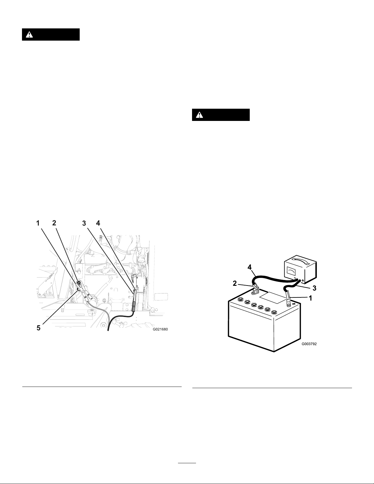
ConnectingaBoosterBattery
1
2
3
4
G003792
WARNING
Chargingthebatteryproducesgassesthatcan
explode.
Note:Iftheenginestartsandthenstops,donot
operatethestartermotoruntilthestartermotorstops
turning.Donotoperatethestartermotorformore
than30secondsatonetime.Wait30secondsbefore
operatingthestartermotortocoolthemotorandto
buildupthechargeinthebattery.
Neversmokenearthebatteryandkeepsparksand
amesawayfrombattery.
Note:Thisprocedurerequires2peopletoperform.Ensure
thatthepersonmakingtheconnectionswearstheproperface
protectionandprotectiveglovesandclothing.
1.EnsurethatallcontrolsareintheNeutralpositionand
thattheparkingbrakeisintheOnposition.
2.Sitintheoperatorseatandhavetheotherpersonmake
theconnections.
Note:Ensurethatthejumperbatteryisa12-volt
battery.
Important:Ifyouareusinganothermachine
forpower,ensurethatthe2machinesarenot
touchingeachother.
3.Preparetostarttheengine;refertosteps1through6
ofStartingtheEngine(page25).
4.Removethecoverfromthejumppost(Figure56).
8.Whentheenginestarts,havetheotherperson
disconnectthenegative(-)jumpercablefromtheframe
andthendisconnectthepositive(+)jumpercable.
ChargingtheBattery
WARNING
Chargingthebatteryproducesgassesthatcan
explode.
Neversmokenearthebattery,andkeepsparksand
amesawayfromthebattery.
Important:Alwayskeepthebatteryfullycharged.This
isespeciallyimportanttopreventbatterydamagewhen
thetemperatureisbelow32°F(0°C).
1.Cleantheexteriorofthebatterycaseandthebattery
posts.
Note:Connecttheleadsofthebatterychargerto
batterypostsbeforeconnectingthechargertothe
electricalsource.
2.Connectthepositiveleadofthebatterychargertothe
positive-batterypost(Figure57).
Figure56
1.Jumper-cableclamp
(positive)
2.Jumppost
3.Groundpoint(alternator
nut)
5.Connectthepositive(+)jumpercabletothejumppost
(Figure56).
6.Connectthenegative(-)jumpercabletoaground
point,suchasthenutatthepivotpointforthe
alternator(Figure56).
7.Starttheengine;refertosteps7through10inStarting
theEngine(page25).
4.Jumper-cableclamp
(negative)
5.Cover
Figure57
1.Positive-batterypost
2.Negative-batterypost
3.Red(+)chargerlead
4.Black(-)chargerlead
3.Connectthenegativeleadofthebatterychargertothe
negative-batterypost(Figure57).
4.Connectthebatterychargertotheelectricalsource.
Important:Donotoverchargethebattery.
Note:Chargethebatteryasshowninthefollowing
table:
46
Page 47
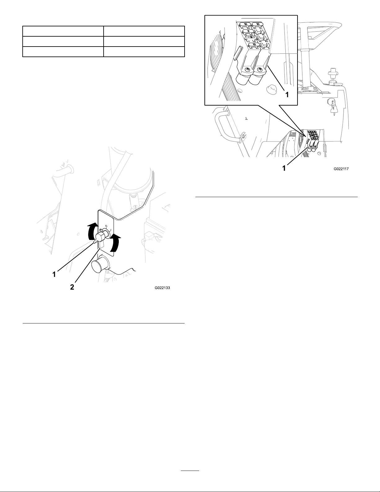
BatteryChargingTable
ChargerSettingChargingTime
4to6amperes30minutes
25to30amperes10to15minutes
5.Whenthebatteryisfullycharged,unplugthecharger
fromtheelectricalsource,thendisconnectthecharger
leadsfromthebatteryposts(Figure57).
ReplacingaFuse
1.Removetherightsidepanel;refertoRemovingthe
SidePanels(page35).
2.Rotatethebattery-disconnectswitchcounterclockwise
totheOffposition(Figure58).
Figure59
1.Fuseblock
Figure58
1.Battery-disconnectswitch
intheOnposition
2.Battery-disconnectswitch
intheOffposition
3.Replacetheopen(blown)fuseinthefuseblockwitha
newfusethathasanequivalentamperagevalue(Figure
59).
4.Rotatethebattery-disconnectswitchclockwisetothe
Onposition(Figure17).
5.Installtherightsidepanel;refertoInstallingtheSide
Panels(page36).
47
Page 48
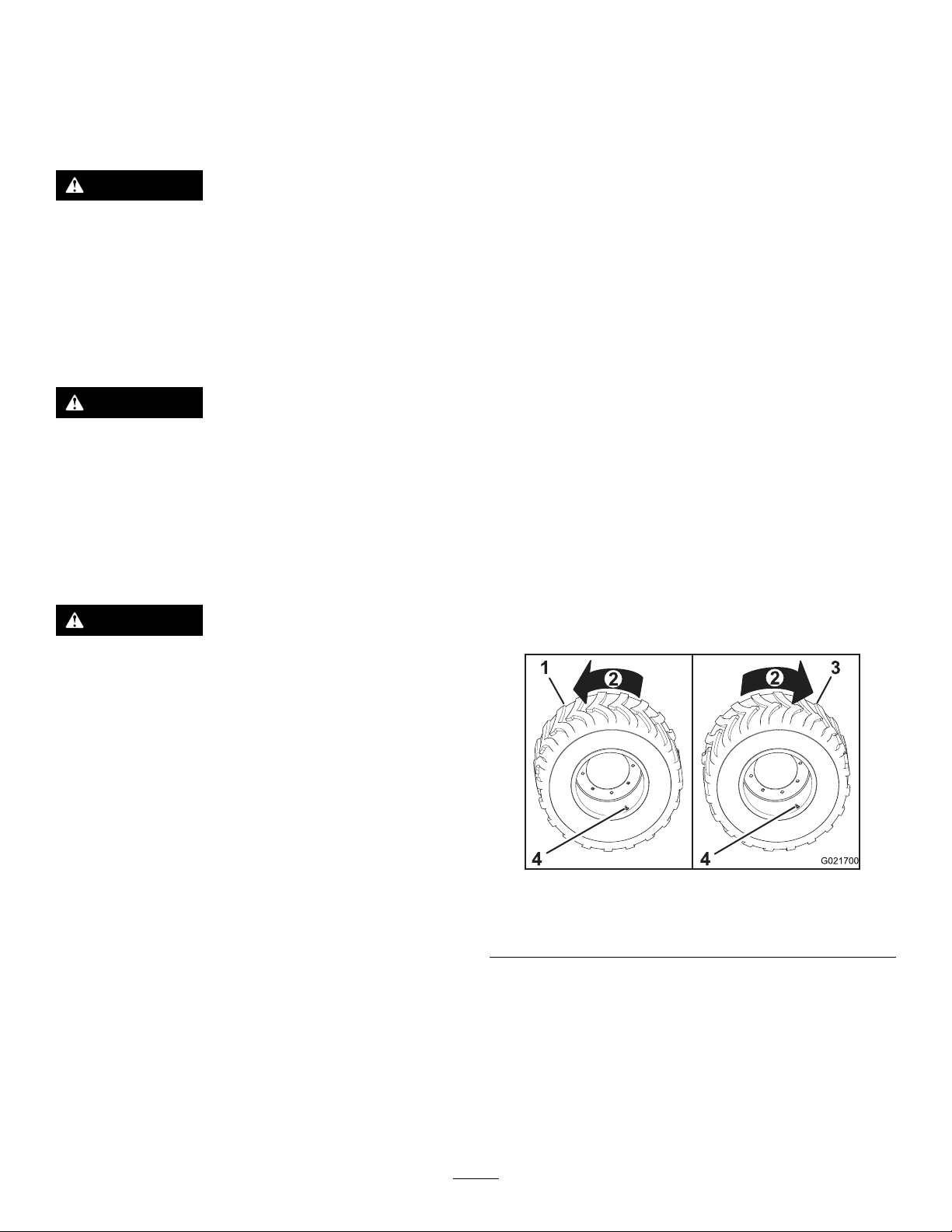
DriveSystem
Maintenance
Note:Beforeyouaddair,ensurethatthetireis
properlyinstalledonthemachine,orputthewheelina
restrainingdevice,suchasatireinationcage.
2.Removethecapfromthevalvestem.
ServicingtheTires
WARNING
Explodingtiresand/orrimpartscancauseinjury
ordeath.
Keepyourselfandothersoutoftheareaofdanger.
Standonthetreadsideofthetire.Alwaysll
thetirestothecorrectairpressure,andfollow
theinstructionsinthismanualforaddingairor
servicingthetires.
WARNING
Donotweldthewheelorrimwiththetireinstalled.
Weldingwithanexplosiveair/gasmixturecan
ignite,causingseriousinjuryordeath,regardlessof
whetherthetireisinatedordeated.
Removingtheairorbreakingthebeadisnot
adequate;youmustcompletelyremovethetirefrom
therimbeforewelding.
WARNING
Anexplosiveseparationofthetireand/orrimparts
cancauseinjuryordeath.
3.Attachtheself-lockingchuckoftheairhosetothe
valvestem.
4.Wheninatingthetirewhileitismountedtothe
machine,standbehindthetreadofthetire.
Note:Ensurethatallpersonsareawayfromtheside
ofthetirebeforeyoustarttoaddair.
5.Opentheremoteshutoffvalvetoinatethetiretothe
speciedpressure,thenclosethevalve.
Important:Donotinatethetiremorethanthe
recommendedpressure.
6.Removetheairchuckfromthevalvestem.
7.Installthecaponthevalvestem.
MaintainingtheTiresandWheels
Alwayshaveaqualiedtiretechnicianservicethetiresand
wheelsofthismachine.Topreventaccidents,usearestraining
device(suchasatireinationcage),thecorrectequipment,
andthecorrectprocedure.
Important:Thereare2differenttire-treadpatternand
wheelcombinations;theleft-sidetiresandtheright-side
tiresaredifferent.Ensurethatthetreaddirectionofthe
tireandthevalvesteminthewheelarecorrectlyaligned
beforeinstallingthetiretotherim.
Haveaqualiedtiremechanicservicethetire.
CheckingtheTiresandWheels
ServiceInterval:Beforeeachuseordaily
1.Checkeachtireforembeddedobjects,separatedplies,
missingtread,bulges,oradamagedbead,andreplace
it,ifnecessary.
2.Checkeachwheelforsignsofunusualbendingor
damage,andreplaceit,ifnecessary.
MaintainingtheAirPressureinthe
Tires
ServiceInterval:Every50hours
Important:Maintaintheairpressureinthetiresat310
kPa(45psi).
1.Measuretheairpressureinthetires;ifthetirepressure
isnotattherecommendedpressure,completetherest
ofthisprocedure.
Important:Useanairhosewitharemoteshutoff
valveandaself-lockingchuck.
Figure60
1.Left-sidetire
2.Forward4.Valvestem
3.Right-sidetire
TorquingtheWheelNuts
1.Ensurethatthemountingangeofthewheelisush
againstthemountingangeoftheaxle.
2.Incrementallytorquethewheelnutsforeachwheel
asfollows:
A.Torquetheallwheelnutsto100N-m(75ft-lb)in
thesequenceshowninFigure61.
48
Page 49
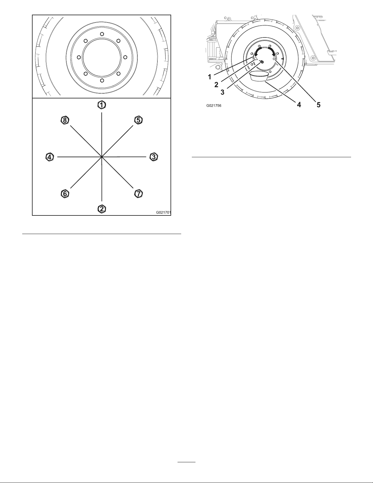
Figure61
B.Torqueallthenutsto200N-m(150ft-lb)inthe
sequenceshowninFigure61.
C.Torqueallthenutsto300N-m(225ft-lb)inthe
sequenceshowninFigure61.
Figure62
1.Wheelhub4.Drainpan
2.Oilportatthe9o’clock
position
3.Plug
3.Stoptheengine,settheparkingbrake,andremovethe
ignitionkey .
4.Placeadrainpanunderthedrainportinthewheelhub
(Figure62).
5.Removetheplugfromthewheelhub(Figure62).
6.Checkthattheoillevelisatthebottomofthethreads
oftheoilport(Figure62).
5.Oilportatthe3o’clock
position(alternative)
•Iftheoillevelistoohigh,allowtheoiltodrain
fromtheoilport.
•Iftheoillevelistoolow,addoiltothewheelhub
throughtheoilport;refertostep6inChanging
theWheelHubOil(page49).
7.ChecktheconditionoftheO-ringontheplug.
ServicingtheAxlesandthe Transmission
CheckingtheOilLevelintheWheel
Hubs
ServiceInterval:Aftertherst100hours
Every250hours
Note:Haveanotherpersonhelpyoualigntheoilplugsin
theaxleswhenyouservicetheaxleoil.
1.Ensurethatthemachineisonalevelsurfaceandthat
alltheattachmentsareinthetransportposition.
2.Movethemachineforwardorbackwarduntiltheplug
forthewheelhubisateitherthe3o’clockor9o’clock
position(Figure62).
Note:ReplacetheO-ringifitiswornordamaged.
8.Installtheplugintheoilportofthewheelhub(Figure
62).
9.Repeatsteps2through8fortheotherwheelhubs.
ChangingtheWheelHubOil
ServiceInterval:Aftertherst200hours
Every1,000hours
Oilspecication:SAE80W140APIclassicationlevelGL4
Wheelhuboilcapacity:approximately0.62L(0.65USqt)
ToroPremiumGearOilisavailablefromanAuthorizedToro
ServiceDealer.Seethepartscatalogforpartnumbers.
Note:Ifpossible,changetheoilwhenitiswarm.
1.Movethemachineforwardorbackwarduntiltheoil
plugforthewheelhubisatthe6o’clockposition
(Figure63).
49
Page 50
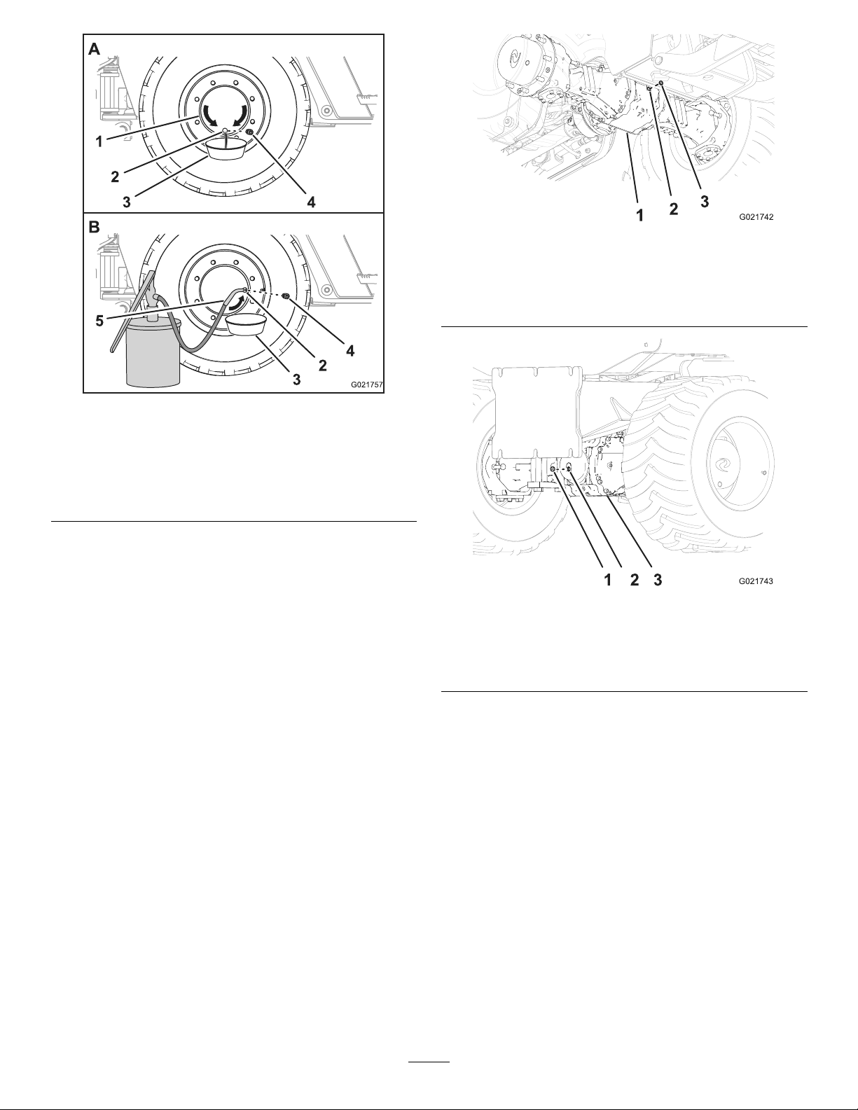
Figure64
FrontAxle
Figure63
1.Wheelhub
2.Oilportatthe6o’clock
position
3.Drainpan
4.Oilportatthe3o’clock
position
5.Plug
6.Oilservicingequipment
2.Placeadrainpanundertheoilportofthewheelhub
(Figure63).
3.Removethepluganddraintheoilfromtheplanetary
(Figure63).
4.ChecktheconditionoftheO-ringfortheplug.
Note:ReplacetheO-ringifitiswornordamaged.
5.Movethemachineforwardorbackwarduntiltheoil
plugforthewheelhubiseitheratthe3o’clockorthe9
o’clockposition(Figure63).
6.Addthespeciedoiltothewheelhubthroughtheoil
portuntiltheoillevelisatthebottomofthethreads
oftheport.
7.Installtheplugintheoilportofthewheelhub.
8.Repeatthisprocedurefortheotherwheelhubs.
1.Pinionhousing(frontaxle)
2.Sightport
1.Plug
2.Siteport
3.Plug
Figure65
RearAxle
3.Pinionhousing(rearaxle)
3.Lookthroughthesightportandcheckthattheoillevel
intheaxleislevelwiththebottomofthethreadsof
theport(Figure64andFigure65).
Note:Useaashlightandamirrortohelpyousee
theoillevel.
•Iftheoillevelistoohigh,allowtheoiltodrain
fromthesightport.
CheckingtheOilLevelintheAxles
ServiceInterval:Aftertherst100hours
Every250hours
1.Placeadrainpanunderthepinionhousingoftheaxle.
2.Removetheplugfromthesightportinthepinion
housingoftheaxle.
•Iftheoillevelistoolow,addoiltothepinion
housingandaxlethroughthesightport;referto
steps6and7inChangingtheOilintheAxles
(page51).
4.Cleanthethreadsofthesightplug.
5.ApplyPTFEthreadsealingtapetothethreadsofthe
plug.
6.Installthesightplugintothesightportinthepinion
housingoftheaxle(Figure64andFigure65).
50
Page 51
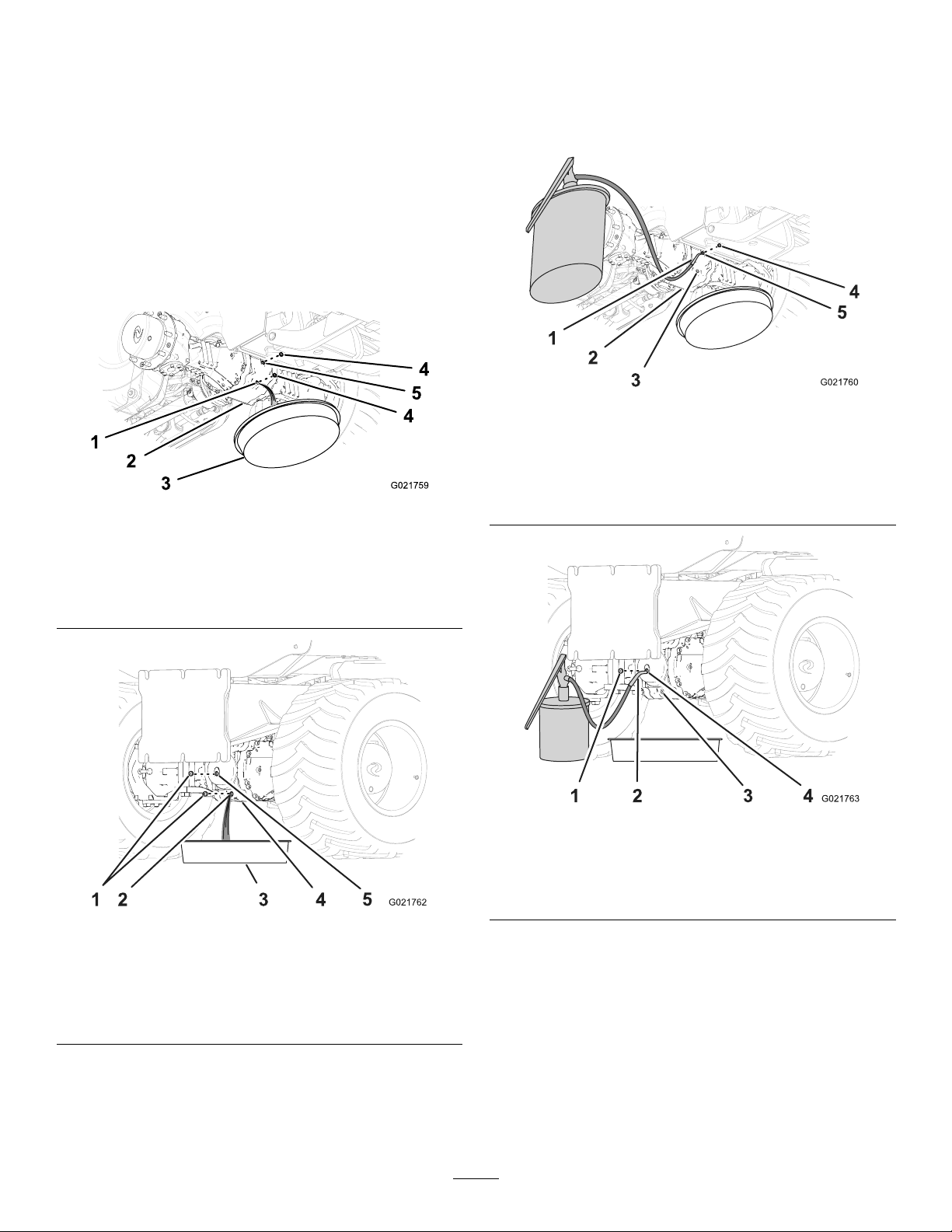
ChangingtheOilintheAxles
ServiceInterval:Aftertherst200hours
Every1,000hours
Oilspecication:SAE80W140APIclassicationlevelGL4
Frontaxleoilcapacity:approximately3.8L(4.0USqt)
Rearaxleoilcapacity:approximately3.8L(4.0USqt)
ToroPremiumGearOilisavailablefromanAuthorizedToro
ServiceDealer.Seethepartscatalogforpartnumbers.
1.Placeadrainpanunderthepinionhousingoftheaxle
(Figure66andFigure67).
Figure66
FrontAxle
3.Cleanthethreadsoftheplugs.
4.ApplyPTFEthreadsealingtapetothethreadsofthe
plugs.
5.Installoneoftheplugsintothedrainport(Figure68
andFigure69).
Figure68
FrontAxle
1.Oilservicingequipment4.Plug(sightport)
2.Pinionhousing
3.Plug(drainport)
5.Sightport
1.Drainport4.Plug
2.Pinionhousing
3.Drainpan
1.Plug4.Pinionhousing
2.Drainport
3.Drainpan
5.Sightport
Figure67
RearAxle
5.Sightport
2.Removetheplugsfromthesightportandthedrain
portofthepinionhousing(Figure66andFigure67).
Note:Allowtheoiltodraincompletelyfromthe
pinionhousingandaxle.
Figure69
RearAxle
1.Plug
2.Oilservicingequipment4.Sightport
3.Plug(drainport)
6.Fillthepinionhousingandaxlewiththespeciedoil
throughthesightportuntiltheoilislevelwiththe
threadsatthebottomoftheport(Figure68andFigure
69).
7.Waitafewminutesfortheoiltosettle,thenaddmore
oilasnecessary.
Note:Continuetoaddoiluntiltheoillevelstabilizes
andisatthebottomofthethreadsofthesightport.
8.Installtheremainingplugintothesightportofthe
pinionhousing(Figure68andFigure69).
51
Page 52
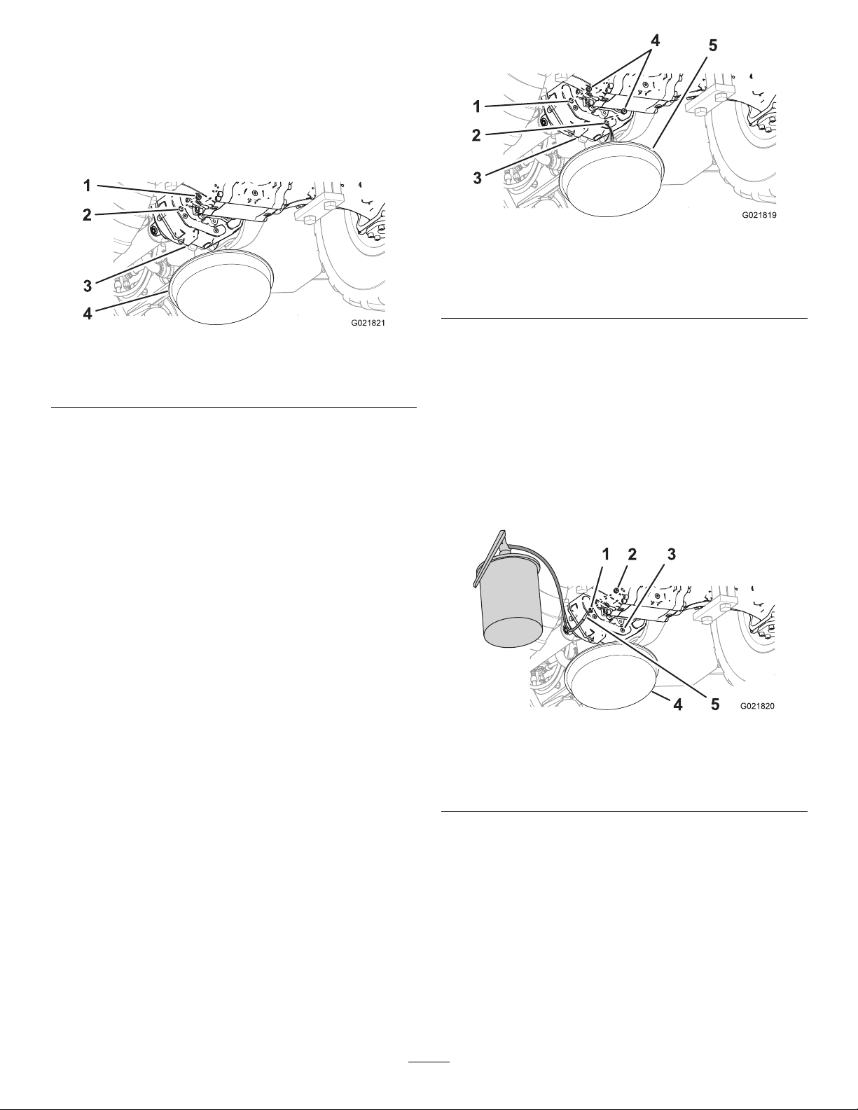
CheckingtheOilLevelinthe
Transmission
ServiceInterval:Aftertherst100hours
Every250hours
1.Placeadrainpanunderthebacksideofthe
transmissionhousing(Figure70).
Figure71
Figure70
1.Plug3.Transmissionhousing
2.Sightport
4.Drainpan
2.Removetheplugfromthesightportinthetransmission
(Figure70).
3.Lookthroughthesightportandcheckthattheoillevel
inthetransmissionislevelwiththebottomofthe
threadsoftheport(Figure70).
Note:Useaashlightandamirrortohelpyousee
theoillevel.
•Iftheoillevelistoohigh,allowtheoiltodrain
fromthesightport.
•Iftheoillevelistoolow,addoiltothetransmission
throughthesightport;refertosteps6and8in
ChangingtheOilintheTransmission(page52).
1.Sightport
2.Drainport5.Drainpan
3.Transmissionhousing
4.Plug
2.Removetheplugsfromthedrainportandthesight
portinthetransmissionhousing(Figure71).
Note:Allowtheoiltodraincompletelyfromthe
pinionhousingandaxle.
3.Cleanthethreadsoftheplugs.
4.ApplyPTFEthread-sealingtapetothethreadsofthe
plugs.
5.Installoneoftheplugsintothedrainportofthe
transmission(Figure72).
4.Cleanthethreadsofthesightplug.
5.ApplyPTFEthreadsealingtapetothethreadsofthe
plug.
6.Installthesightplugintothesightportofthe
transmissionhousing(Figure70).
ChangingtheOilintheTransmission
ServiceInterval:Aftertherst200hours
Every1,000hours
Oilspecication:SAE80W140APIclassicationlevelGL4
Transmissionoilcapacity:approximately1.7L(1.8USqt)
ToroPremiumGearOilisavailablefromanAuthorizedToro
ServiceDealer.Seethepartscatalogforpartnumbers.
Note:Ifpossible,changetheoilwhenitiswarm.
1.Placeadrainpanunderthebacksideofthe
transmissionhousing(Figure71).
Figure72
1.Sightport
2.Plug
3.Transmissionhousing
4.Drainpan
5.Oilservicingequipment
6.Fillthetransmissionwiththespeciedoilthroughthe
sightportuntiltheoilislevelwiththethreadsatthe
bottomoftheport(Figure72).
7.Waitafewminutesfortheoiltosettle,thenaddmore
oilasnecessary.
Note:Continuetoaddoiluntiltheoillevelisstabilizes
andatthebottomofthethreadsofthesightport.
8.Installtheremainingpluginthesightportofthe
transmission(Figure72).
52
Page 53
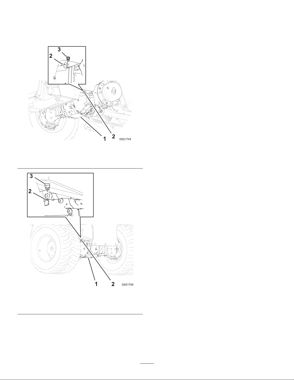
CleaningtheAxleBreathers
ServiceInterval:Every300hours
1.Cleantheareaaroundthebreatherswithacleaning
solvent(Figure73andFigure74).
Figure73
Important:Wearfaceprotectionwhenusing
compressedair.
6.Installthebreatherinthefrontaxle(Figure73).
7.Installthebreatherintherearaxle(Figure74).
1.Frontaxle
2.Breatherport
3.Breathertting
Figure74
1.Rearaxle
2.Breatherport
3.Breathertting
2.Removethebreatherfromthefrontaxle(Figure73).
3.Removethebreatherfromtherearaxle(Figure74).
4.Cleanthebreatherswithacleaningsolvent.
5.Usecompressedairtodrythebreathers.
53
Page 54
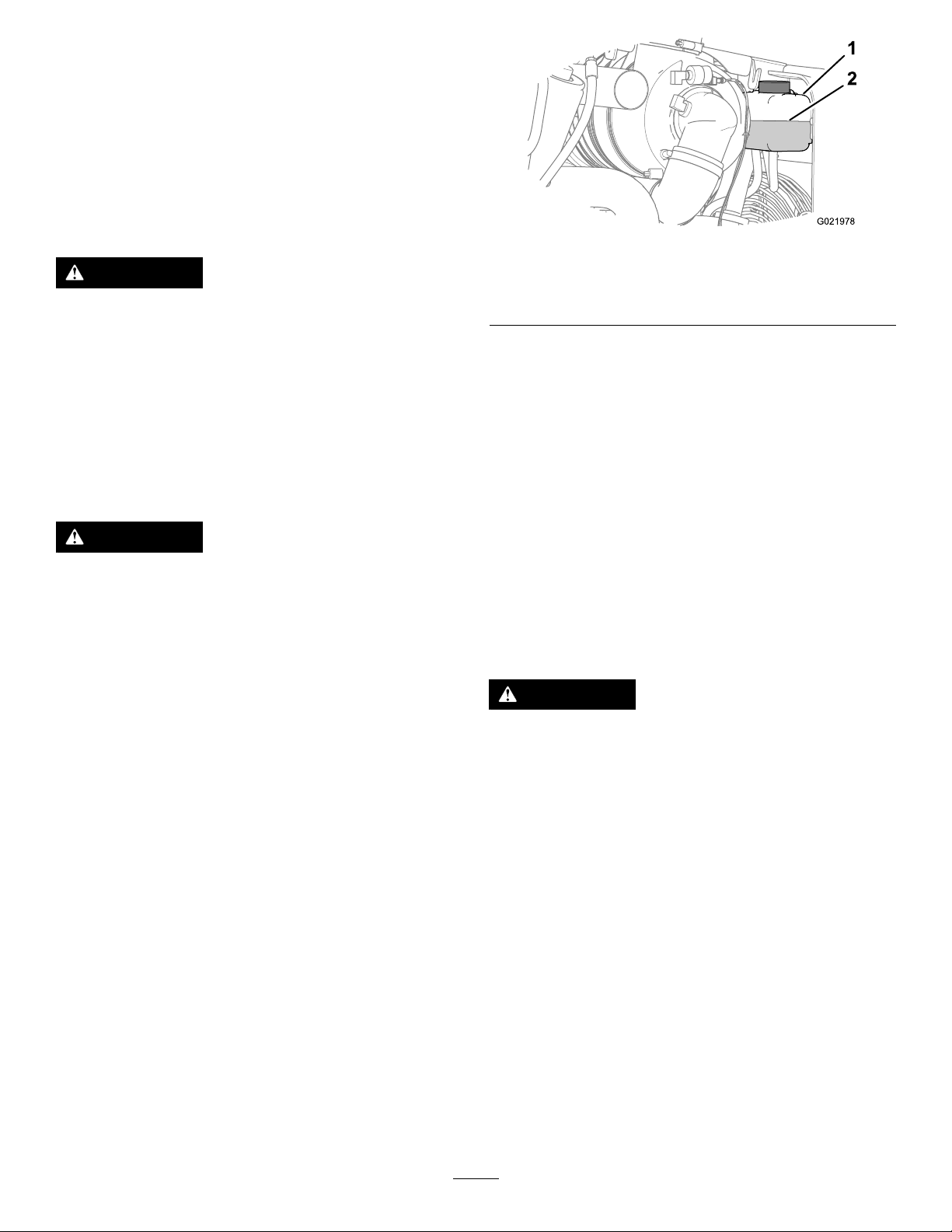
CoolingSystem
Maintenance
ServicingtheCoolingSystem
Coolantspecication:amixtureof50%ethyleneglycol
and50%water
EngineandRadiatorcoolantcapacity:17.2L(18.2USqt)
WARNING
Ifyouremovetheradiatorcapfromahotengine,
hotcoolantcouldspray,causingscalding.
•Wearfaceprotectionwhenopeningtheradiator
cap.
•Allowthecoolingsystemtocooldowntobelow
50°C(120°F)beforeremovingtheradiatorcap.
•Followtheinstructionsforcheckingand
maintainingtheenginecoolingsystem.
WARNING
Coolantistoxic.
•Keepcoolantawayfromchildrenandpets.
•Ifyouarenotre-usingthecoolant,disposeofit
accordingtolocalenvironmentalregulations.
Figure75
1.Reservoir
Note:Ensurethatthecoolantlevelisbetweenthe
AddmarkandtheFullmarkonthereservoir(Figure
75).
5.Addthespeciedcoolantuntilthecoolantlevelis
halfwaybetweentheAddmarkandtheFullmarkon
thereservoir.
Note:Ensurethatthecoolantsolutionisthoroughly
mixedbeforellingthereservoir.
6.Installtherightsidepanel;refertoInstallingtheSide
Panels(page36).
2.Coolantlevel(halfway
betweentheAddandFull
marks)
CheckingtheCoolantLevelinthe
Radiator
ServiceInterval:Every50hours
CheckingtheCoolantLevelinthe
Reservoir
ServiceInterval:Beforeeachuseordaily
Note:Donotremovetheradiatorllercapduringthis
procedure.
1.Parkthemachineonalevelsurface,stoptheengine,
andremovetheignitionkey.
2.Allowtheenginetocool.
3.Removetherightsidepanel;refertoRemovingthe
SidePanels(page35).
4.Checkthecoolantlevelinthereservoir(Figure75).
WARNING
Iftheenginehasbeenrunning,theradiatorwill
pressurizedandthecoolantinsidewillbehot.If
youremovethecap,coolantmaysprayout,causing
severeburns.
•Donotremovetheradiatorcaptocheckcoolant
levels.
•Donotremovetheradiatorcapwhentheengine
ishot.Allowtheenginetocoolforatleast15
minutesoruntiltheradiatorcapiscoolenough
totouchwithoutburningyourhand.
Note:Thecoolingsystemislledwithantifreezehavinga
mixtureof50%ethyleneglycoland50%water.
1.Parkthemachineonalevelsurface,stoptheengine,
andremovetheignitionkey.
2.Allowtheenginetocool.
3.Removethenosepanel;refertoRemovingtheNose
Panel(page36).
4.Opentheventvalvefortheengine(Figure76).
54
Page 55
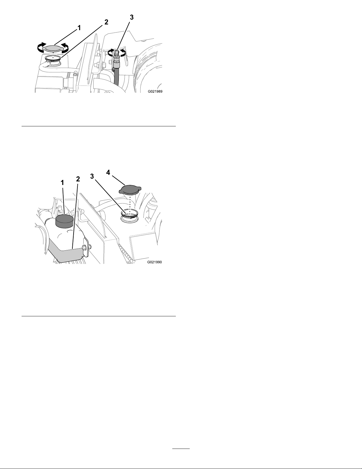
Figure76
1.Radiatorcap3.Ventvalve
2.Fillerneck
5.Removetheradiatorcapfromthellerneckofthe
radiatorandcheckthecoolantlevel(Figure76and
Figure77),
Note:Thecoolantshouldbeuptothellerneck.
CheckingtheConditionofCooling
SystemComponents
ServiceInterval:Every300hours
Checktheconditionofthecoolingsystemforleaks,damage,
dirt,andloosehoses,andclamps.Clean,repair,tighten,and
replacethecomponentsasnecessary.
CheckingtheConcentrationofthe
Coolant
ServiceInterval:Every1,000hours
Testtheconcentrationofethyleneglycolbasedantifreezein
thecoolant.Ensurethatthecoolantisamixtureof50%
ethyleneglycoland50%water.
Note:Anantifreezehavingamixtureof50%ethylene
glycoland50%waterwillprotecttheengineto-37°C(-34°F)
throughouttheyear.
Checktheconcentrationofthecoolantmixturetoensurethat
itisamixtureof50%ethyleneglycoland50%water.
Figure77
1.Reservoir
2.Coolantlevel(halfway
betweentheAddandFull
marks)
3.Coolantlevel(bottomof
radiatorneck)
4.Radiatorcap
6.Ifthecoolantlevelislow,addcoolantuntilthelevelis
uptothebottomofthellerneck(Figure77).
Important:Donotoverlltheradiator.
Note:Iftheradiatorcoolantlevelislowandthe
coolantreservoirlevelisattheFullmark,checkforair
leaksinthehosebetweentheradiatorandthecoolant
reservoir.
CleaningtheCoolingSystem
ServiceInterval:Every2,000hours/Every2years
(whichevercomesrst)
DrainingtheCoolantfromtheSystem
Important:Donotpourcoolantontothegroundorinto
anunapprovedcontainerthatcanleak.
1.Removetheleftandrightsidepanelsandthenose
panel;refertoRemovingtheSidePanels(page35)and
RemovingtheNosePanel(page36).
2.Removetheradiatorcap(Figure76andFigure77).
3.Placeadrainpanwithaminimumcapacityof20L(5.3
gallons)undertheopenendofthedrainhose(Figure
78).
Note:Thecoolantcapacityofboththeengineand
theradiatoris17.2L(18.2USqt).
7.Closetheventvalve.
8.Installtheradiatorllercap,ensuringthatitistightly
sealed.
9.Iftheairtemperatureisbelow0°C(32°F),mixthe
ethyleneglycolandwatercompletelybyrunningthe
engineatoperatingtemperaturefor5minutes.
55
Page 56
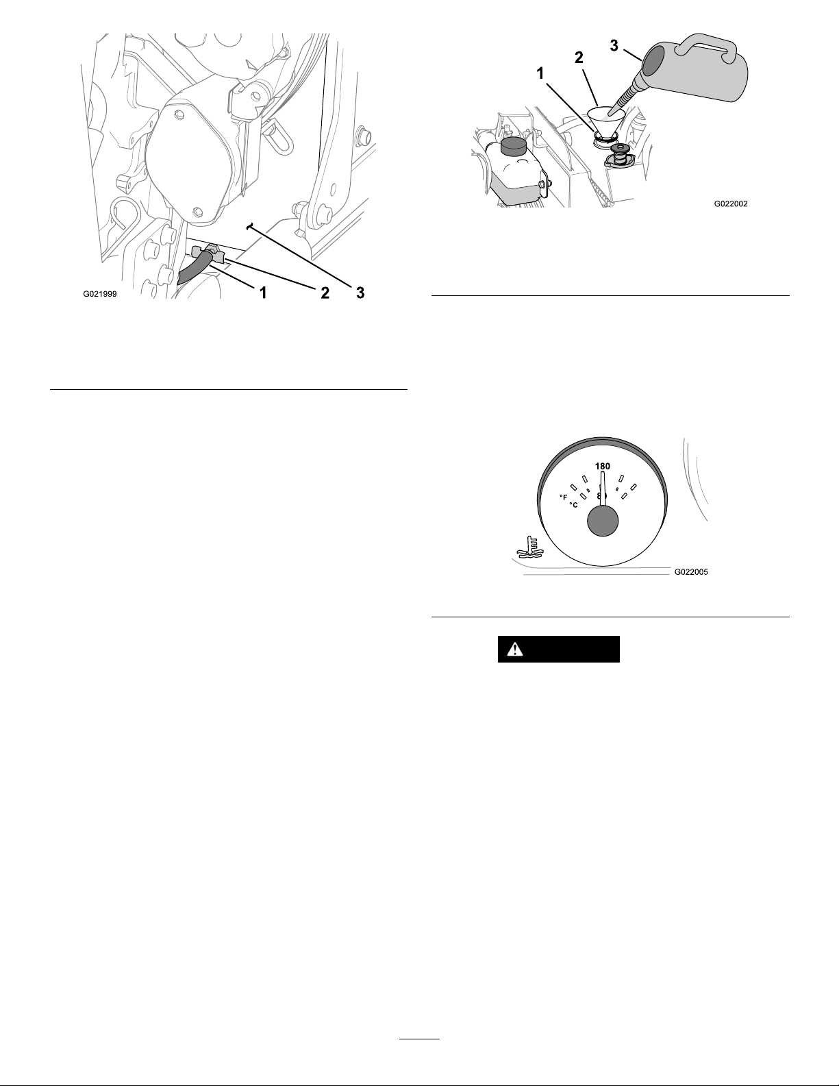
Figure79
Figure78
1.Drainhose
2.Drainvalve
3.Radiatorshroud(lower-left
area)
4.Openthedrainvalveontheradiator,andallowthe
coolanttodraincompletely.
Note:Disposeoftheusedcoolantproperlyaccording
tolocalcodes.
5.Closethedrainvalve(Figure78).
FlushingtheCoolingSystem
Engineandradiatorcoolantcapacity:17.2liter(18.2US
qt)
1.Conditionthecoolingsystemasfollows:
A.Ensurethatthecoolantisdrainedfromthe
radiatorandthatthedrainvalveisclosed.
B.Opentheventvalve(Figure76).
C.Addacoolingsystemcleaningsolutiontotheto
theradiatorthroughthellerneck(Figure79).
Note:Usecleaningsolutionofsodiumcarbonate
andwater(oracommerciallyavailableequivalent).
Followthedirectionsthatcomewiththecleaning
solution.
1.Coolantsystemcleaning
solution
2.Funnel
3.Fillerneck(radiator)
D.Closetheventvalve.
Important:Donotinstalltheradiatorcap.
E.Operatetheenginefor5minutesoruntilthe
coolanttemperaturegaugeintheinstrument
clusterindicates82°C(180°F),thenstopthe
engine(Figure80).
Figure80
CAUTION
Thecleaningsolutionishotandcan
causeburns.
Stayawayfromthedischargeendofthe
coolantdrainhose.
F.Openthedrainvalveanddrainthecleaning
solutionintoadrainpan(Figure78).
G.Closethedrainvalve.
2.Flushthecoolingsystemasfollows:
A.Opentheventvalve(Figure76).
B.Filltheradiatorwithcleanwater(Figure81).
56
Page 57
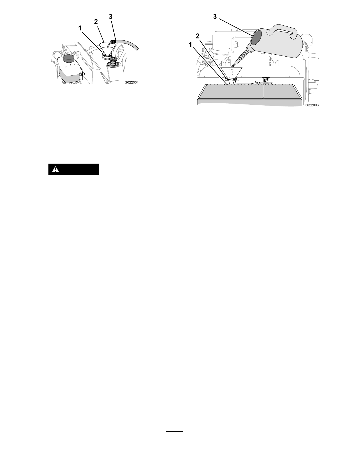
Figure81
1.Fillerneck
2.Funnel
3.Cleanwater
C.Closetheventvalve.
D.Operatetheenginefor5minutesoruntilthe
coolanttemperaturegaugeintheinstrument
clusterindicates82°C(180°F),thenstopthe
engine.
CAUTION
Thewaterishotandcancauseburns.
Stayawayfromthedischargeendofthe
coolantdrainhose.
E.Openthedrainvalve(Figure78)anddrainthe
waterintoadrainpan.
F.Ifthewaterdrainedfromtheradiatorisdirty,
performsteps2-Athrough2-Euntilthewater
drainedfromtheradiatorisclean.
G.Closethedrainvalve.
FillingtheSystemwithCoolant
Figure82
1.Coolantlevel(atthe
bottomofthellerneck)
2.Fillerneck
3.Coolant(amixtureof50%
ethyleneglycoland50%
water)
4.Closetheventvalve.
5.Installtheradiatorcap.
6.Installthenosepanel;refertoInstallingtheNosePanel
(page37).
7.FillthecoolantreservoirwithcoolantuptotheFull
mark.
8.Installthecoolantreservoircap.
9.Starttheengineandrunitathalfthrottlefor5minutes.
10.Stoptheengineandremovethekey.
11.Wait30minutes,thenchecktheuidlevelinthe
coolantreservoir.Ifitislow,addcoolant.
12.Installthesidepanels;refertoInstallingtheSidePanels
(page36).
Important:Fillthecoolingsystemproperlytoprevent
airlocksinthecoolingpassages.Failingtoventthe
coolingsystemproperlycandamageit.
Note:Useamixtureof50%ethyleneglycoland50%water
inthemachine.Thelowestambientoperatingtemperature
forthismixtureisabove-37°C(-34°F).Iftheambient
temperatureislower,adjustthemixture.Useamixtureof
ethyleneglycolandwaterinthemachineallyear.
1.Removetheradiatorcap(Figure76andFigure77).
2.Opentheventvalve(Figure76).
3.Fillthecoolingradiatorwiththespeciedcoolant
mixtureuntiltheuidlevelisuptothetopoftheller
neck(Figure82).
Note:Thecoolantcapacityofboththeengineand
theradiatoris17.2L(18.2USqt).
57
Page 58
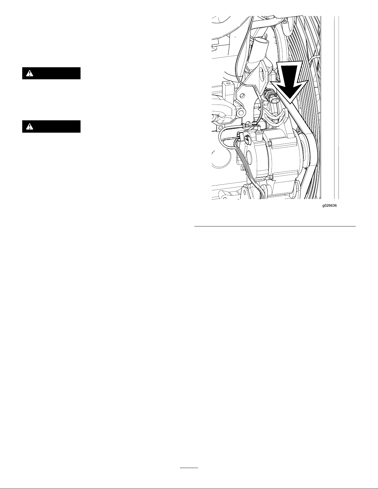
BeltMaintenance
ServicingtheEngineDrive Belt
WARNING
Stoptheengineandremovetheignitionkeybefore
youbegintoperformanymaintenanceorrepair
work.
WARNING
Contactingarotatingbeltcancauseseriousinjury
ordeath.
Alwaysstoptheengineandremovetheignitionkey
beforeworkingnearbelts.
CheckingtheConditionoftheBelt
ServiceInterval:Every250hours
1.Removetheright-sidepanel;refertoRemovingthe
SidePanels(page35).
2.Inspectthebeltforcuts,cracks,loosecords,grease,oil,
twisting,orsignsofabnormalwear.
Note:Replacethebeltifitisexcessivelywornor
damaged;refertoInstallingtheBelt(page60).
3.Installtheright-sidepanel;refertoInstallingtheSide
Panels(page36).
CheckingtheTensionoftheBelt
ServiceInterval:Every1,000hours
1.Removetherightsidepanel;refertoRemovingthe
SidePanels(page35).
2.Placeastraightedgeoverthedrivebeltandacrossthe
pulleys(Figure83).
Figure83
3.Pressthebeltdownatthemidwaypointbetweenthe
fanpulleyandthealternatorpulleyasshowninFigure
83.
Note:Therangeofbeltdeectionbetweenthe
straightedgeandthebeltshouldbe7to9mm(0.28to
0.35inches)underaloadof10kg(22lb).
4.Ifthetensionofthebeltisaboveorbelowthespecied
range,adjustthedrivebelttension;refertoAdjusting
theTensionoftheBelt(page58).
5.Installtherightsidepanel;refertoInstallingtheSide
Panels(page36).
AdjustingtheTensionoftheBelt
1.Loosenthenutandboltatthepivotpointforthe
alternator(Figure84).
58
Page 59
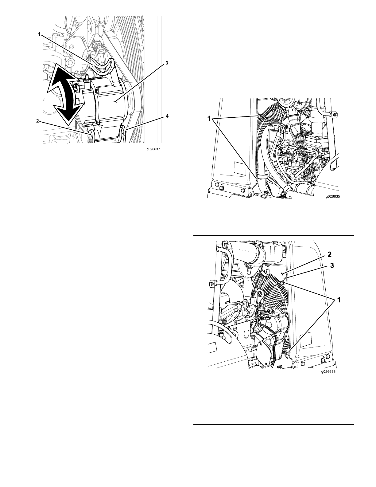
Figure84
1.Adjustmentbolt3.Alternator
2.Nut(alternatorpivotpoint)4.Bolt(alternatorpivotpoint)
2.Loosentheadjustmentboltonthealternator(Figure
84).
3.Loosentheboltonthemountingbracketontheengine
(ifnecessary).
4.Movethealternatorawayfromtheenginetoincrease
thebelttension;movethealternatortowardtheengine
todecreasethebelttension(Figure84).
4.Loosentheengineboltandthealternatormounting
bracket.
5.Movethealternatortowardtheenginetoloosen
thebeltenoughsothatyoucanremoveitfromthe
alternatorpulley(Figure84).
6.Removethebeltfromthegroovesofthealternator,
thefan,andthecrankshaftpulleys.
7.Removethe4boltsthatsecurethefanguardtothefan
shroud(Figure85).
Figure85
Leftsideofthemachine
1.Bolts
5.Tightenthealternatoradjustmentbolt(Figure84).
6.Checkthetensionofthebelt;refertoCheckingthe
TensionoftheBelt(page58).
7.Ifthebelttensioniscorrect,tightenthenutandboltat
thepivotpointforthealternator(Figure84);otherwise
repeatsteps2through6.
8.SwitchthebatterydisconnectswitchtotheOn
position;refertoBattery-disconnectSwitch(page21).
9.Installtherightsidepanel;refertoInstallingtheSide
Panels(page36).
ReplacingtheEngineDrive Belt
RemovingtheBelt
1.Removetheleftandrightsidepanels;referto
RemovingtheSidePanels(page35).
2.Loosenthenutandboltatthepivotpointforthe
alternator(Figure84).
3.Loosentheadjustmentboltonthealternator(Figure
84).
Figure86
Rightsideofthemachine
1.Bolts3.Fanguardmountingtab
(4)
2.Fanshroud
8.Rotatethefanguardcounterclockwisearoundthedrive
shaftofthefanuntiltheopeningintheguardisatthe
4o’clockposition.
59
Page 60
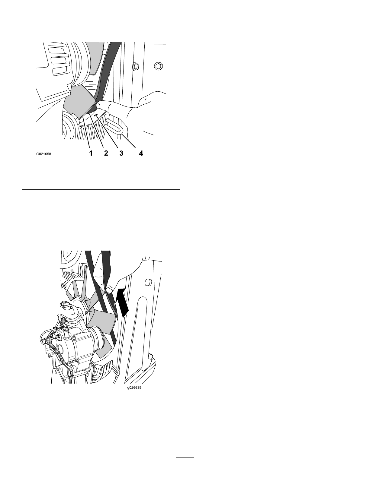
9.Atthe4o’clockpositionofthefanshroud,alignthe
G021658
1
2
3
4
beltbetweenthetipofthefanbladeandtheopening
intheshroud(Figure87).
InstallingtheBelt
1.Alignthebeltbetween2ofthefanblades,andcarefully
pushthebeltforwardanddownuntilitisinfrontof
thefan(Figure88).
2.Moveafanbladetothe4o’clockposition.
3.Alignthebeltbetweenthetipofthefanbladeandthe
openingintheshroud(Figure87).
4.Movethebeltrearwardandpastthetipofthefanblade.
5.Repeatsteps2through4fortheremainingfanblades.
6.Alignthebeltinthegroovesofthealternator,thefan,
andthecrankshaftpulleys.
7.Rotatethefanguardclockwisearoundthedriveshaft
ofthefanuntiltheopeningintheguardisatthe6
o’clockposition(Figure85).
8.Securethefanguardtothefanshroud(Figure85).
Figure87
1.Fanblade3.Fanshroud
2.Belt4.Fanguard
10.Movethebelttotheforwardsideofthefanblade.
11.Rotatethefancounterclockwiseandrepeatsteps9and
10fortheremainingfanblades.
12.Alignthebeltbetween2ofthefanblades,then
carefullypullthebeltrearwardandupuntilyoucan
removeitfromthemachine(Figure88).
9.Adjustthetensionofthebelt;refertoAdjustingthe
TensionoftheBelt(page58).
Note:Ensurethatthebeltisalignedinthegroovesof
thepulleys.
Figure88
60
Page 61
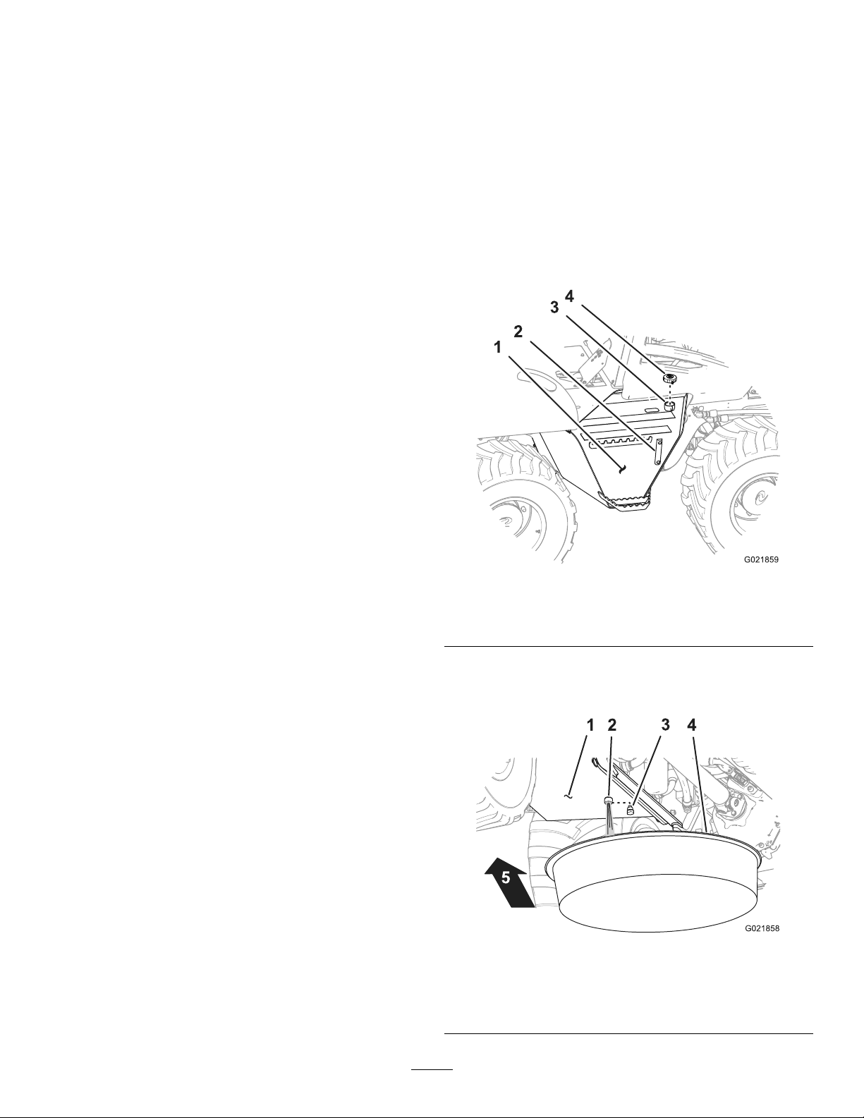
HydraulicSystem
Maintenance
ServicingtheHydraulic System
Themachinecomesfromthefactorywithafullhydraulic
uidreservoirthatcontainsapproximately75.7L(20.0US
gal)ofhigh-qualityhydraulicuid.Checkthelevelofthe
hydraulicuidbeforeyoustarttheenginefortherst
time,anddailythereafter.
UseToroPremiumAll-seasonHydraulicFluid(available
in5-gallonpailsor55-gallondrums.Seethepartscatalogor
anAuthorizedT oroServiceDealerforpartnumbers).
IfTorohydraulicuidisnotavailable,youmayusean
equivalenthydraulicuid,providedthatitmeetsallthe
followingmaterialpropertiesandindustryspecications.Do
notuseasynthetichydraulicuid.Consultwithyour
lubricantdistributortoidentifyasatisfactoryproduct.
Note:T orodoesnotassumeresponsibilityfordamage
causedbyimpropersubstitutions,souseonlyproductsfrom
reputablemanufacturers.
ChangingtheHydraulicFluid
ServiceInterval:Every1,000hours
DrainingtheHydraulicReservoir
1.Parkthemachineonalevelsurface,andputallthe
attachmentsinthetransportposition.
2.Stoptheengine,settheparkingbrake,andremovethe
ignitionkey .
Note:Drainthehydraulicuidreservoirwhenthe
uidiswarm,ifpossible.
3.Removethellcap/breatherfromthelltube(Figure
89).
HighViscosityIndex/LowPourPointAnti-wear
HydraulicFluid,ISOVG46
MaterialProperties:
St@40°C(104°F):44to48 Viscosity,ASTMD445
St@100°C(212°F):7.9to8.5
ViscosityIndexASTM
D2270
PourPoint,ASTMD97-37°C(-34°F)to-45°C(-49°F)
FZG,Failstage
Watercontent(newuid)500ppm(maximum)
IndustrySpecications:VickersI-286-S(QualityLevel),
VickersM-2950-S(Quality
Level),DenisonHF-0
140to160
11orbetter
Note:Manybrandsofhydraulicuidsarealmostcolorless,
makingitdifculttospotleaks.Areddyeadditiveforthe
hydraulicsystemoilisavailablein20ml(0.68oz)bottles.
Onebottleissufcientfor15.1to22.7L(4.0to6.0USgal)
ofhydraulicoil.Orderpartno.44-2500fromanAuthorized
ToroServiceDealer.
Note:Ifambientoperatingtemperaturesexceed110°F ,
contactT oroforuidrecommendations.
Figure89
1.Hydraulicreservoir3.Filltube
2.Sightgauge4.Fillcap/breather
4.Placeacontainerthatcanholdaminimumof75.7L
(20.0USgal)underthehydraulicreservoirdrainplug
(Figure90).
Figure90
1.Hydraulicreservoir4.Drainpan
2.Drainport5.Forward
3.Plug
61
Page 62
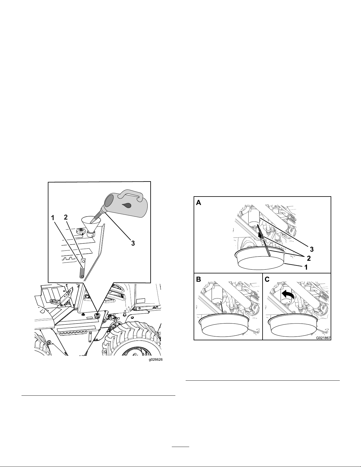
5.Removethedrainplugfromthehydraulicreservoir
(locatedunderneaththereservoir),anddrainthe
reservoir(Figure90).
Note:Thecapacityofthereservoirisapproximately
75.7L(20.0USgal);thecapacityofthecomplete
systemisapproximately98.4L(26.0USgal).
6.ExaminetheconditionoftheO-ringonthedrainplug.
Note:ReplacetheO-ringifitiswornordamaged.
7.Installthedrainplug(Figure90).
Important:Changethehydraulic-pressure
andhydraulic-returnlterswhenyouchange
thehydraulicuid;refertoChangingthe
Hydraulic-pressureFilter(page62)andChanging
theHydraulic-returnFilter(page63).
4.Installtheright-sidepanel;refertoInstallingtheSide
Panels(page36).
5.Cleanthellcap/breatherwithsolvent.
6.Installthellcap/breather(Figure91).
7.Starttheengineandletitidleforapproximately2
minutes.
8.Stoptheengineandremovetheignitionkey.
9.Checkaroundthepressureandreturnltersforleaks.
10.Checkthedrainplugforleaks.
11.Checkthelevelofthehydraulicuidandllthe
reservoirtothemiddleofthesightglassasneeded.
ChangingtheHydraulic-pressureFilter
FillingtheHydraulic-uidReservoir
1.Fillthehydraulic-uidreservoirwiththespecied
hydraulicuiduntiltheuidlevelisatthemidpointof
thesightgauge(Figure91).
ServiceInterval:Every500hours
Note:Y oucanaccessthehydraulic-pressurelterfrom
undertherightsideofthemachine,behindthehydraulic
reservoir(Figure92).
1.Placeacontainerunderthehydraulic-pressurelter
(Figure92).
Figure91
1.Filllevel(midpoint)3.Hydraulicuid
2.Sightgauge
2.Removetheright-sidepanel;refertoRemovingthe
SidePanels(page35).
3.Removethebreatherhose,cleanandinspectit,then
installthehose.
Figure92
1.Containersuitablefor
hydraulicuid
2.Sharpobject
3.Hydraulic-pressurelter
2.Puncturethebottomofthehydraulic-pressurelter,
andallowtheresidualhydraulicuidtodrainintothe
container(Figure92).
Note:Useatapered-centerpunchorawltopuncture
theltercase.
62
Page 63
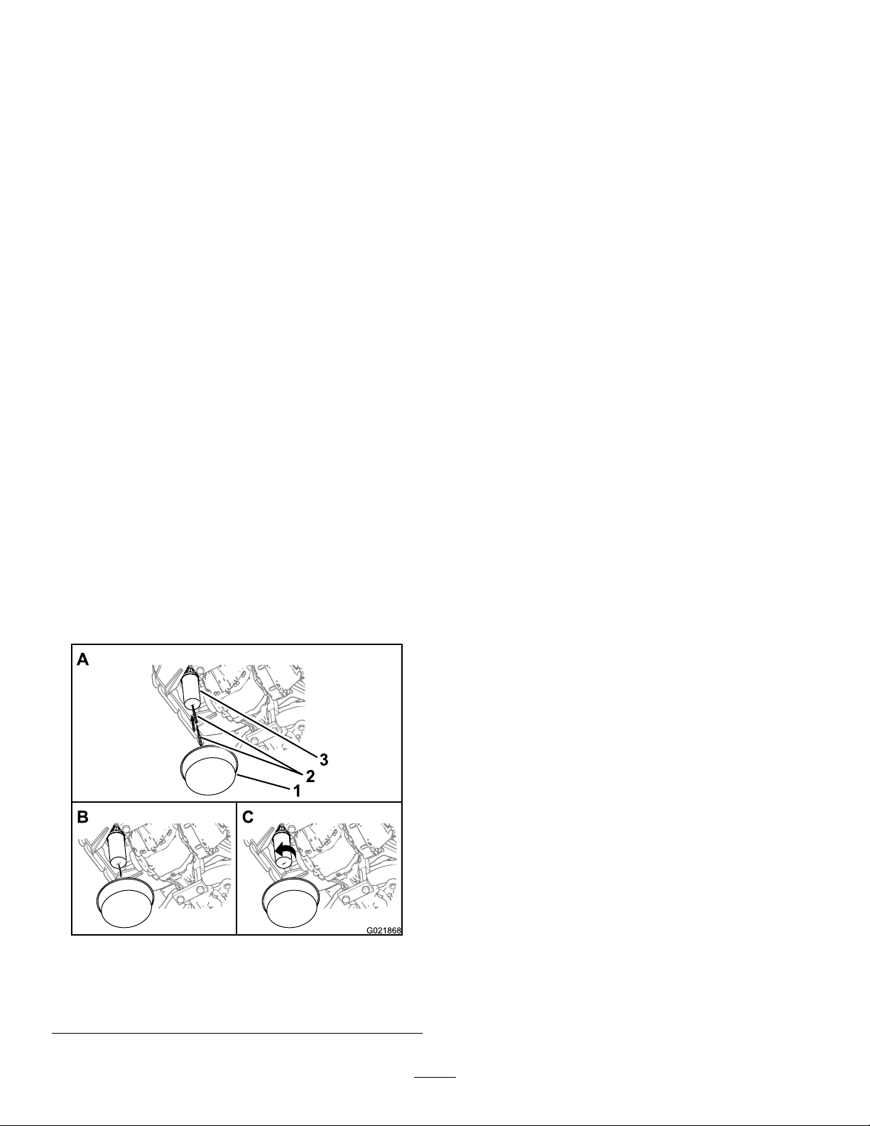
3.Rotatethehydraulic-pressureltercounterclockwise
andremovethelter(Figure92).
Note:Discardthelter.
4.Applyathinlayerofthespeciedhydraulicuidto
theO-ringofthenewlter.
Important:Donotusealterstrapwrenchto
tightenthelter.Astrapwrenchcandentthe
lter,causingittoleak.
2.Puncturethebottomofthehydraulic-pressurelter
andallowtheresidualhydraulicuidtodraininthe
container(Figure93).
Note:Useatapered-centerpunchorawltopuncture
theltercase.
3.Rotatethehydraulic-returnltercounterclockwiseand
removethelter(Figure93).
Note:Discardthelterproperly.
5.Installthenewlter.
Note:Useyourhandstotightenthelteranadditional
halfturnaftertheltermakescontactwiththelter
head.
6.Checkthelevelofthehydraulicuidinthehydraulic
reservoir;refertoCheckingtheHydraulicFluidLevel
(page24).
7.Starttheengineandletitidlefor1or2minutes.
8.Stoptheengine.
9.Checkforleaksaroundthelterarea.
10.Checkthelevelofthehydraulicuidinthehydraulic
reservoir,andadduid,ifnecessary.
ChangingtheHydraulic-returnFilter
ServiceInterval:Every500hours
Note:Youcanaccessthehydraulic-returnlterfrom
underneaththerearofthemachine(Figure93).
1.Placeacontainerunderthehydraulic-pressurelter
(Figure93).
4.Applyathinlayerofthespeciedhydraulicuidto
theO-ringofthenewlter.
Important:Donotusealterstrapwrenchto
tightenthelter.Astrapwrenchcandentthe
lter,causingittoleak.
5.Installthenewlter.
Note:Useyourhandstotightenthelteranadditional
halfturnaftertheltermakescontactwiththelter
head.
6.Checkthelevelofthehydraulicuidinthehydraulic
reservoir;refertoCheckingtheHydraulicFluidLevel
(page24).
7.Starttheengineandrunitatidlefor1or2minutes.
8.Stoptheengineandremovethekey.
9.Checkaroundthelterforleaks.
10.Checktheuidlevelofthehydraulicreservoir,andadd
uid,ifnecessary.
1.Containersuitablefor
hydraulicuid
2.Sharpobject
Figure93
3.Hydraulicreturnlter
63
Page 64
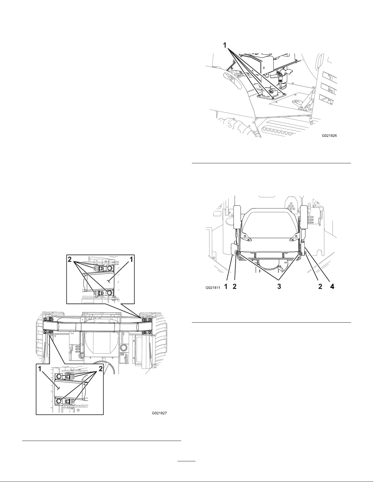
ROPSMaintenance
CheckingandServicingthe ROPS
CheckingandCaringfortheSeatBelt
Beforeyouoperatethemachine,alwaysensurethattheROPS
andtheseatbeltareproperlyinstalledandingoodworking
order.
1.Checktheseatbeltfordamage,andreplaceallparts
thataredamaged.
2.Ensurethatthemountingboltsfortheseatbeltsare
tight.
3.Keeptheseatbeltscleanusingonlysoapandwater.
Note:Donotimmersetheseatbeltsinbleachordye,
becausethisweakensthebeltmaterial.
CheckingandMaintainingtheROPS
2.Checkthatthe4boltsthatsecuretheseattothechassis
ofthemachinearetorquedto5.4to6.8N-m(48to60
in-lb);refertoFigure95.
Figure95
1.Bolt
3.Checkthattheboltsandnutsthatattachtheseat-belt
retractorandbuckletotheseataretorquedto7.8to
9.6N-m(69to85in-lb);refertoFigure96.
ServiceInterval:Every500hours
Important:IfanypartoftheROPSsystemisdamaged,
replaceitbeforeyouoperatethemachine.
1.Checkthatthe8boltsthatsecuretheROPSbartothe
chassisofthemachinearetorquedto24.4to26.1N-m
(216to231in-lb);refertoFigure94.
Figure96
1.Seat-beltretractor
2.Bolt4.Buckle
Note:Replaceanypartsthatarewornordamaged.
4.InspecttheROPSforcracks,rust,orholesinthe
ROPSandcomponentparts.
Note:Age,weather,andaccidentscausedamageto
theROPSandROPSparts.Ifyouhaveanydoubts
abouttheROPSsystem,contactanAuthorizedToro
ServiceDealer.
3.Nut
1.ROPSbar
Figure94
2.Bolt
64
Page 65

ReplacingaDamagedROPSSystem
IftheROPSsystemhasbeendamagedinanaccident,such
asarolloverorhittinganoverheadobjectduringtransport,
replaceanydamagedROPScomponentstorestoretheROPS
systemtoitsoriginallevelofprotection.
Afteranaccident,checkthefollowingitemsfordamage:
•TheROPSbar
•Operatorseat
•Seatbeltmounting
•Seatbelt
Beforeyouoperatethemachine,replacealldamagedROPS
components;contactanAuthorizedToroServiceDealer.
Important:Donottrytoweldorstraightenadamaged
ROPSbar.
Cleaning
RemovingDirtandDebrisfrom theMachine
Important:Operatingtheenginewithblockedscreens,
dirtyorpluggedcoolingns,and/orcoolingshrouds
removed,willresultinenginedamagefromoverheating.
1.Lowerallattachmentsandsettheparkingbrake.
2.Stoptheengine,removethekey,andwaitforallmoving
partstostopbeforeleavingtheoperatingposition.
3.Wipeawaydirtanddebrisfromtheaircleaner.
4.Cleananydirtanddebrisbuildupontheenginewitha
brushorblower.
Important:Itispreferabletoblowdirtout,rather
thanwashingitout.Ifwaterisused,keepitaway
fromelectricalitemsandhydraulicvalves.Do
notuseahigh-pressurewasher.High-pressure
washingcandamagetheelectricalsystemand
hydraulicvalvesordepletegrease.
65
Page 66

Storage
3.Starttheengineandrunitatidlespeedfor
approximately2minutes.
PreparingforSeasonal Storage
Forstorageover30days,preparethemachine,the
attachments,andtheengineasfollows:
PreparingtheMachineand
Attachments
1.Thoroughlycleanthemachineandalltheattachments;
refertoRemovingDirtandDebrisfromtheMachine
(page65).
2.Loweralltheattachmentsandsettheparkingbrake.
3.Stoptheengine,removethekey,andwaitforallmoving
partstostopbeforeleavingtheoperatingposition.
4.Checkthetirepressureandadjustit,ifnecessary;refer
toMaintainingtheAirPressureintheTires(page48).
5.Checkallfastenersandtightenthemasnecessary.
6.Greaseallttingsandpivotpointsandwipeupany
excessgrease;refertoGreasingtheMachine(page33).
4.Stoptheengine.
5.Flushthefueltankwithfresh,cleandieselfuel.
6.Secureallthefuelsystemttings.
7.Servicetheaircleaner;refertoServicingtheAir-cleaner
System(page39).
8.Sealtheaircleanerinletandtheexhaustoutletwith
plasticandweatherprooftape.
9.Checktheantifreezeprotectionandadda50%
ethyleneglycoland50%watersolutionofanti-freeze
asneededfortheexpectedminimumtemperaturein
yourarea.
7.Repairanydentsinthemachineortheattachments,
andlightlysandandpaintareasthatarebare,scratched,
chipped,orrusted.Paintisavailablefroman
AuthorizedToroServiceDealer.
8.Servicethebatteryandthecablesasfollows:
A.Removethebatteryterminalsfromthebattery
posts.
B.Cleanthebattery,terminals,andpostswithawire
brushandbakingsodasolution.
C.Coatthecableterminalsandbatterypostswith
Grafo112Xskin-overgrease(T oroPartNo.
505-47)orequivalentgrease.
D.Slowlyrechargethebatteryevery60daysfor24
hourstopreventleadsulfationofthebattery.
9.Checkandtightenallbolts,nuts,andscrews.Repairor
replaceanypartthatisdamaged.
10.Storethemachineinaclean,drygarageorstoragearea.
Removethekeyfromtheignitionswitchandkeepitin
amemorableplace.
11.Coverthemachinetoprotectitandkeepitclean.
PreparingtheEngine
1.Removedirtandgrimefromtheexternalpartsofthe
engine.Cleandirtandchafffromtheoutsideofthe
enginecylinder-headnsandblowerhousing.
2.Changetheengineoilandtheoillter;referto
ChangingtheEngineOil(page38).
66
Page 67

Troubleshooting
Problem
Thestarterdoesnotcrank.
1.Theenginecranksbutwillnotstart.
PossibleCauseCorrectiveAction
1.Theelectricalconnectionsare
corrodedorloose.
2.Afuseisblown.2.Replacethefuse.
3.Afuseisloose.3.Installthefuse.
4.Thebatteryisdischarged.
5.Therelayorswitchisdamaged.
6.Thestarterorstartersolenoidis
damaged.
7.Internalenginecomponentshave
seizedup.
1.Thestartingprocedureisincorrect.
2.Thefueltankisempty .2.Fillthefueltankwithfreshfuel.
3.Thefuelshutoffvalveisclosed.3.Openthefuelshutoffvalve.
4.Thereisdirt,water,stalefuel,or
incorrectfuelinthefuelsystem.
5.Thefuellineisclogged.5.Cleanorreplacethefuelline.
6.Thereisairinthefuel.6.Bleedthenozzlesandcheckforair
7.Theglowplugsdonotoperate.
8.Thecrankingspeedisslow.
9.Theaircleaningsystemelementsare
dirty.
10.Thefuellterisclogged.10.Replacethefuellter .
11.Thefuelisnotthepropergradefor
cold-weatheruse.
12.Theenginehaslowcompression.
13.Theinjectionnozzlesorpumpare
malfunctioning.
1.Checktheelectricalconnectionsfor
goodcontact.
4.Chargethebatteryorreplaceit.
5.ContactyourAuthorizedService
Dealer.
6.ContactyourAuthorizedService
Dealer.
7.ContactyourAuthorizedService
Dealer.
1.RefertoStartingtheEnginein
Operation.
4.Drainandushthefuelsystem;add
freshfuel.
leaksatthefuelhoseconnections
andttingsbetweenthefueltankand
engine.
7.Checkthefuse,glowplugs,andwiring.
8.Checkthebattery,oilviscosity,and
startingmotor(contactyourAuthorized
ServiceDealer).
9.Servicetheaircleaningsystem
elements.
11.Drainthefuelsystem,replacethefuel
lter,andaddfreshfuelhavingthe
propergradeforambienttemperature
conditions.Youmayneedtowarmup
theentiremachine.
12.ContactyourAuthorizedService
Dealer.
13.ContactyourAuthorizedService
Dealer.
Theenginestartsbutdoesnotkeep
running.
1.Thefueltankventisrestricted.1.Loosenthecap.Iftheenginerunswith
2.Thereisdirtorwaterinthefuelsystem.2.Drainandushthefuelsystem;add
3.Thefuellterisclogged.3.Replacethefuellter.
4.Thereisairinthefuel.4.Bleedthenozzlesandcheckforair
5.Thefuelisnotthepropergradefor
cold-weatheruse.
6.Thefuelpumpisdamaged.6.ContactyourAuthorizedService
thecaploosened,replacethecap.
freshfuel.
leaksatfuelhoseconnectionsand
ttingsbetweenthefueltankandthe
engine.
5.Drainthefuelsystem,replacethefuel
lter,andaddfreshfuelhavingthe
propergradeforambienttemperature
conditions.Youmayneedtowarmup
theentiremachine.
Dealer.
67
Page 68

Problem
PossibleCauseCorrectiveAction
Theenginerunsbutknocksormisses.
Theengineisoverheated.
1.Thereisdirtorwaterinthefuelsystem.1.Drainandushthefuelsystem;add
2.Theengineoverheats.
3.Thereisairinthefuel.3.Bleedthenozzleandcheckforair
4.Theinjectionnozzlesaredamaged.
5.Theenginehaslowcompression.
6.Theinjectionpumptimingisincorrect.
7.Thereisexcessivecarbonbuildup.
8.Theenginehasinternalwearor
damage.
1.Thecoolantlevelistoolow .
2.Theairowtotheradiatorisrestricted.
3.Theengineoilleveliseithertoolowor
toohigh.
4.Themachineisunderanexcessive
load.
5.Thereisimproperfuelinthefuel
system.
6.Thethermostatisdamaged.
7.Thefanbeltislooseorbroken.7.ContactyourAuthorizedService
8.Theinjectiontimingisincorrect.
9.Thecoolantpumpisdamaged.
freshfuel.
2.Checktheengineoillevelandaddoil
asneeded;alsocheckandservicethe
coolantsystem,ifnecessary .
leaksatthefuelhoseconnectionsand
thettingsbetweenthefueltankand
theengine.
4.ContactyourAuthorizedService
Dealer.
5.ContactyourAuthorizedService
Dealer.
6.ContactyourAuthorizedService
Dealer.
7.ContactyourAuthorizedService
Dealer.
8.ContactyourAuthorizedService
Dealer.
1.Checkthecoolantlevelandadd
coolanttothesystem.
2.Inspectandcleantheradiatorscreen.
3.Eitheraddordraintheengineoiluntil
theoillevelisattheFullmark.
4.Reducetheloadonthemachine;
operatethemachineataslower
groundspeed.
5.Drainandushthefuelsystem,then
addfreshfuel.
6.ContactyourAuthorizedService
Dealer.
Dealer.
8.ContactyourAuthorizedService
Dealer.
9.ContactyourAuthorizedService
Dealer.
Thereisexcessiveblacksmokeinthe
exhaust.
1.Theengineisunderanexcessiveload.
2.Theaircleaningsystemelementsare
dirty.
3.Thereisimproperfuelinthefuel
system.
4.Theinjectionpumptimingisincorrect.
5.Theinjectionpumpisdamaged.
6.Theinjectionnozzlesaredamaged.
68
1.Reducethegroundspeedofthe
machine.
2.Servicetheaircleaningsystem
elements.
3.Drainandushthefuelsystem,then
addfreshfuel.
4.ContactyourAuthorizedService
Dealer.
5.ContactyourAuthorizedService
Dealer.
6.ContactyourAuthorizedService
Dealer.
Page 69

Problem
PossibleCauseCorrectiveAction
Thereisexcessivewhitesmokeinthe
exhaust.
Theenginelosespower.
1.ThekeywasturnedtotheStartposition
beforetheglowpluglightturnedoff.
2.Theenginetemperatureislow.
3.Theglowplugsarenotoperating.
4.Theinjectionpumptimingisincorrect.
5.Theinjectionnozzlesaredamaged.
6.Theenginehaslowcompression.
1.Theengineisunderanexcessiveload.
2.Theengineoilleveliseithertoolowor
toohigh.
3.Theaircleaningsystemelementsare
dirty.
4.Thereisdirtorwaterinthefuelsystem.4.Drainandushthefuelsystem;add
5.Theengineoverheats.
6.Thereisairinthefuel.6.Bleedthenozzleandcheckforair
7.Theenginehaslowcompression.
8.Thefueltankventisrestricted.8.Loosenthecap.Iftheenginerunswith
9.Theinjectionpumptimingisincorrect.
10.Theinjectionpumpisdamaged.
1.TurnthekeytotheRunpositionand
allowtheglowpluglighttoturnoff
beforestartingtheengine.
2.Checkthethermostatandreplaceitif
necessary.
3.Checkthefuse,glowplugs,andwiring.
4.ContactyourAuthorizedService
Dealer.
5.ContactyourAuthorizedService
Dealer.
6.ContactyourAuthorizedService
Dealer.
1.Reducethegroundspeedofthe
machine.
2.Eitheraddordraintheengineoiluntil
theoillevelisattheFullmark.
3.Servicetheaircleaningsystem
elements.
freshfuel.
5.Checktheengineoillevelandaddoil
asneeded;alsocheckandservicethe
coolantsystem,ifnecessary .
leaksatthefuelhoseconnectionsand
thettingsbetweenthefueltankand
theengine.
7.ContactyourAuthorizedService
Dealer.
thecaploosened,replacethecap.
9.ContactyourAuthorizedService
Dealer.
10.ContactyourAuthorizedService
Dealer.
Themachinedoesnotdrive.
1.Theparkingbrakeisengaged.1.Releasetheparkingbrake.
2.Thehydraulicuidlevelislow.2.Addhydraulicuidtothereservoir.
3.Thetowvalvesareopen.
4.Thepumpand/ormotorisdamaged.4.ContactyourAuthorizedService
5.Thereliefvalveisdamaged.5.ContactyourAuthorizedService
3.Closethetowvalves.
Dealer.
Dealer.
69
Page 70

Notes:
70
Page 71

Notes:
71
Page 72

TheToroUndergroundWarranty
ALimitedWarranty
Underground
Equipment
ConditionsandProductsCovered
TheToroCompanyanditsafliate,T oroWarrantyCompany,pursuant
toanagreementbetweenthem,jointlywarrantyourToroUnderground
Equipment(“Product”)tobefreefromdefectsinmaterialsorworkmanship.
Whereawarrantableconditionexists,wewillrepairtheProduct
atnocosttoyouincludingdiagnostics,labor ,andparts.
ThefollowingwarrantyappliesfromthedatetheProductisdeliveredtothe
originalretailpurchaserorrentalowner.
ProductsWarrantyPeriod
RT600,RT1200,DD2024,and
DD4045
AllOtherEnginePoweredBase
UnitsandFluidMixers
AllSerializedAttachments
RockHammer6months
Engines
2yearsor1500operatinghours,
whicheveroccursrst
1yearor1000operatinghours,
whicheveroccursrst
1year
Throughenginemanufacturers:
2yearsor2000operatinghours,
whicheveroccursrst
InstructionsforObtainingWarrantyService
YouareresponsiblefornotifyingtheUndergroundDealerfromwhomyou
purchasedtheProductassoonasyoubelieveawarrantablecondition
exists.IfyouneedhelplocatingaUndergroundDealer,orifyouhave
questionsregardingyourwarrantyrightsorresponsibilities,youmay
contactusat:
ToroCustomerCare
ToroWarrantyCompany
811 1LyndaleAvenueSouth
Bloomington,MN55420-1196
TollFreeat855-493-0088(U.S.Customers)
1-952-948-4318(InternationalCustomers)
OwnerResponsibilities
AstheProductowner,youareresponsibleforrequiredmaintenanceand
adjustmentsstatedinyourOperator'sManual.Failuretoperformrequired
maintenanceandadjustmentscanbegroundsfordisallowingawarranty
claim.
ItemsandConditionsNotCovered
Notallproductfailuresormalfunctionsthatoccurduringthewarranty
periodaredefectsinmaterialsorworkmanship.Thiswarrantydoesnot
coverthefollowing:
•Productfailureswhichresultfromtheuseofnon-T ororeplacement
parts,orfrominstallationanduseofadd-on,ormodiednon-Toro
brandedaccessoriesandproducts.Aseparatewarrantymaybe
providedbythemanufactureroftheseitems.
•Productfailureswhichresultfromfailuretoperformrecommended
maintenanceand/oradjustments.Failuretoproperlymaintainyour
ToroproductpertheRecommendedMaintenancelistedinthe
Operator’sManualcanresultinclaimsforwarrantybeingdenied.
•ProductfailureswhichresultfromoperatingtheProductinanabusive,
negligent,orrecklessmanner.
•Partssubjecttoconsumptionthroughuseunlessfoundtobedefective.
Examplesofpartswhichareconsumed,orusedup,duringnormal
Productoperationinclude,butarenotlimitedto:brakes,lters,lights,
bulbs,belts,tracksortires,diggingteeth,diggingbooms,digging,
drive,ortrackchains,trackpads,drivesprockets,idlers,rollers,
blades,cuttingedges,orothergroundengagingcomponents.
•Failurescausedbyoutsideinuence.Conditionsconsideredtobe
outsideinuenceinclude,butarenotlimitedto,weather,storage
practices,contamination,useofunapprovedfuels,coolants,lubricants,
additives,water,orchemicals,etc.
•Failureorperformanceissuesduetotheuseoffuels(e.g.gasoline,
diesel,orbiodiesel)thatdonotconformtotheirrespectiveindustry
standards.
•Normalnoise,vibration,wearandtear ,anddeterioration.
•Normal“wearandtear”includes,butisnotlimitedto,damagetoseats
duetowearorabrasion,wornpaintedsurfaces,scratcheddecals,etc.
•Haulingexpenses,traveltime,mileage,orovertimeassociatedwith
transportingproducttotheauthorizedT orodealer.
Parts
Partsscheduledforreplacementasrequiredmaintenanceinthe
Operator’sManual,arewarrantedfortheperiodoftimeuptothescheduled
replacementtimeforthatpart.Partsreplacedunderthiswarrantyare
coveredforthedurationoftheoriginalproductwarrantyandbecomethe
propertyofT oro.T orowillmakethenaldecisionwhethertorepairany
existingpartorassemblyorreplaceit.T oromayuseremanufacturedparts
forwarrantyrepairs.
MaintenanceisatOwner’sExpense
Enginetune-up,lubrication,cleaningandpolishing,replacementoflters,
coolant,andcompletingrecommendedmaintenancearesomeofthe
normalservicesT oroproductsrequirethatareattheowner’sexpense.
GeneralConditions
RepairbyanAuthorizedToroUndergroundDealerisyoursoleremedy
underthiswarranty.
NeitherTheToroCompanynorToroWarrantyCompanyisliablefor
indirect,incidentalorconsequentialdamagesinconnectionwiththe
useoftheToroProductscoveredbythiswarranty,includingany
costorexpenseofprovidingsubstituteequipmentorserviceduring
reasonableperiodsofmalfunctionornon-usependingcompletion
ofrepairsunderthiswarranty.ExceptfortheEmissionswarranty
referencedbelow,ifapplicable,thereisnootherexpresswarranty.All
impliedwarrantiesofmerchantabilityandtnessforusearelimitedto
thedurationofthisexpresswarranty.
Somestatesdonotallowexclusionsofincidentalorconsequential
damages,orlimitationsonhowlonganimpliedwarrantylasts,sotheabove
exclusionsandlimitationsmaynotapplytoyou.Thiswarrantygivesyou
speciclegalrights,andyoumayalsohaveotherrightswhichvaryfrom
statetostate.
Noteregardingenginewarranty:
TheEmissionsControlSystemonyourProductmaybecoveredby
aseparatewarrantymeetingrequirementsestablishedbytheU.S.
EnvironmentalProtectionAgency(EPA)and/ortheCaliforniaAirResources
Board(CARB).Thehourlimitationssetforthabovedonotapplytothe
EmissionsControlSystemWarranty.RefertotheEngineEmissionControl
WarrantyStatementsuppliedwithyourproductorcontainedintheengine
manufacturer’sdocumentationfordetails.
CountriesOtherthantheUnitedStatesorCanada
CustomerswhohavepurchasedT oroproductsexportedfromtheUnitedStatesorCanadashouldcontacttheirT oroDistributor(Dealer)toobtain
guaranteepoliciesforyourcountry ,province,orstate.IfforanyreasonyouaredissatisedwithyourUndergroundDealer’sserviceorhavedifculty
obtainingguaranteeinformation,contacttheToroimporter.
AustralianConsumerLaw:AustraliancustomerswillnddetailsrelatingtotheAustralianConsumerLaweitherinsidetheboxoratyourlocalT oro
Dealer.
374-0292RevA
 Loading...