

Page 1
FormNo.3407-349RevA
DirectDriveTrencher
RT600TractionUnit
ModelNo.25200—SerialNo.316000001andUp
ModelNo.25200E—SerialNo.316000001andUp
Registeratwww.T oro.com.
OriginalInstructions(EN)
*3407-349*A
Page 2

WARNING
CALIFORNIA
Proposition65Warning
Thisproductcontainsachemicalorchemicals
knowntotheStateofCaliforniatocausecancer,
birthdefects,orreproductiveharm.
ModelNo.
SerialNo.
Thismanualidentiespotentialhazardsandhassafety
messagesidentiedbythesafety-alertsymbol(Figure2),
whichsignalsahazardthatmaycauseseriousinjuryordeath
ifyoudonotfollowtherecommendedprecautions.
Introduction
Thisattachmentisdesignedtodigtrenchesinsoiltobury
cablingandpipingforvariousapplications.Itisnotintended
tocutrock,wood,oranyothermaterialotherthansoil.
Readthisinformationcarefullytolearnhowtooperateand
maintainyourproductproperlyandtoavoidinjuryand
productdamage.Youareresponsibleforoperatingthe
productproperlyandsafely.
YoumaycontactTorodirectlyatwww .Toro.comforproduct
andaccessoryinformation,helpndingadealer,ortoregister
yourproduct.
Wheneveryouneedservice,genuineT oroparts,oradditional
information,contactanAuthorizedToroServiceDealer
orToroCustomerServiceandhavethemodelandserial
numbersofyourproductready.Figure1illustratesthe
locationofthemodelandserialnumbersontheproduct.
Writethenumbersinthespaceprovided.
Figure2
1.Safety-alertsymbol
Thismanualuses2wordstohighlightinformation.
Importantcallsattentiontospecialmechanicalinformation
andNoteemphasizesgeneralinformationworthyofspecial
attention.
Contents
Safety...........................................................................3
SafetyandInstructionalDecals.................................4
....................................................................................5
PreparingtheMachine.............................................5
InstallingtheTrencherAttachment............................5
InstallingtheAuger.................................................6
InstallingtheRestraint-BarBrackets...........................6
InstallingtheHydraulicHoses...................................7
InstallingtheBoom.................................................8
InstallingtheDiggingChain.....................................12
Operation....................................................................13
SelectingtheProperComponentsforthe
Trencher............................................................13
UsingtheTrencher.................................................15
OperatingTips......................................................17
Maintenance.................................................................18
GreasingtheTrencher.............................................18
ServicingtheTrencherDiggingChain.......................18
ReplacingtheDiggingChain....................................23
Storage........................................................................25
Troubleshooting...........................................................26
Figure1
1.Locationofthemodelandserialnumberplate
©2016—TheToro®Company
8111LyndaleAvenueSouth
Bloomington,MN55420
Contactusatwww.Toro.com.
2
PrintedintheUSA
AllRightsReserved
Page 3

Safety
Improperlyusingormaintainingthetrenchercan
resultininjury.Toreducethepotentialforinjury,
complywiththesesafetyinstructionsandthoseinthe
machine
safetyalertsymbol,whichmeansCaution,Warning,or
Danger—personalsafetyinstruction.Failuretocomply
withtheinstructionmayresultinpersonalinjuryor
death.
Theremaybeburiedpower,gas,and/ortelephone
linesintheworkarea.Anelectricshockoran
explosionmayoccurifyoudigintoautilityline.
Havethepropertyorworkareamarkedforburied
linesanddonotdiginmarkedareas.Contactyour
localmarkingserviceorutilitycompanytohavethe
propertymarked(forexample,intheUnitedStates,
call811forthenationwidemarkingservice).
Operator’ s Man ual
DANGER
.Alwayspayattentiontothe
WARNING
Lightningcancausesevereinjuryordeath.
Iflightningisseenorthunderisheardinthearea,
donotoperatethemachine;seekshelter.
CAUTION
Hydraulicuidescapingunderpressurecan
penetrateskinandcauseinjury.Fluidinjectedinto
theskinmustbesurgicallyremovedwithinafew
hoursbyadoctorfamiliarwiththisformofinjury;
otherwise,gangrenemayresult.
•Keepyourbodyandhandsawayfrompin-hole
leaksornozzlesthatejecthigh-pressure
hydraulicuid.
•Usecardboardorpapertondhydraulicleaks;
neveruseyourhands.
DANGER
Themovingteethandaugerwillcutorseveryour
hands,feet,orotherbodyparts.
•Keephands,feet,andanyotherpartofyour
bodyorclothingawayfrommovingteeth,auger,
orotherparts.
•Beforeadjusting,cleaning,repairing,or
inspectingthetrencher,lowerthetrenchertothe
ground,shutofftheengine,waitforallmoving
partstostop,andremovethekey.
WARNING
Whentheengineisoff,anattachmentintheraised
positioncangraduallylower.Someonebelow
theattachmentmaybepinnedorinjuredbythe
attachmentasitlowers.
Alwayslowertheattachmenteachtimeyoushut
offthemachine.
CAUTION
Hydraulicttings,hydrauliclines/valves,and
hydraulicuidmaybehotandcanburnyouifyou
touchthem.
•Weargloveswhenmaintaininghydraulic
components.
•Allowthetractionunitandtrenchertocool
beforetouchinghydrauliccomponents.
•Donottouchhydraulicuidspills.
WARNING
Whengoingupordownhill,themachinecould
overturniftheheavyendistowardthedownhill
side.Someonemaybepinnedorseriouslyinjured
bythemachineifitoverturns.
Operatethemachineupanddownslopeswith
theheavyendofthemachineuphill.Anattached
trenchermakesthebackendofthemachineheavy.
3
Page 4
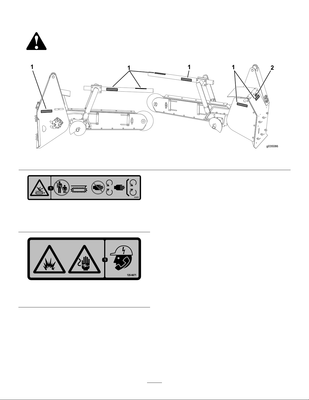
SafetyandInstructionalDecals
Safetydecalsandinstructionsareeasilyvisibletotheoperatorandarelocatednearanyareaofpotential
danger.Replaceanydecalthatisdamagedorlost.
Figure3
1.Decal125-66702.Decal125-6671
125–6670
1.Cutting/dismembermenthazard,trencher—keep
bystandersawayfromthetrencher;keepawayfrommoving
parts;keepallguardsandsafetiesinplace.
125-6671
1.Explosionhazard;electricshockhazard—calllocalutilities
beforedigging.
4
Page 5
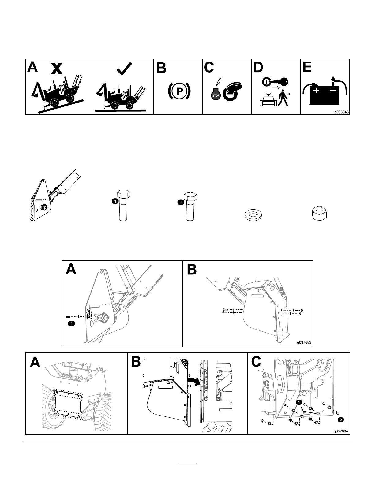
PreparingtheMachine
Important:Ensurethattheliftingequipmenthasa
liftingcapacityofatleast405kg(893lb).
2.Settheparkingbrake.
3.TurnthekeytotheOFFposition.
4.Removethekey.
1.Parkthemachineonalevelsurface.
5.Disconnectthebattery.
InstallingtheTrencherAttachment
Raisetheattachmentofftheoor.
Important:Ensurethattheliftingequipmenthasaliftingcapacityofatleast405kg(893lb).
1x2x4x11x6x
(3/4x2-1/4
inches)
(3/4x2-1/2
inches)(3/4inch)
5
Page 6
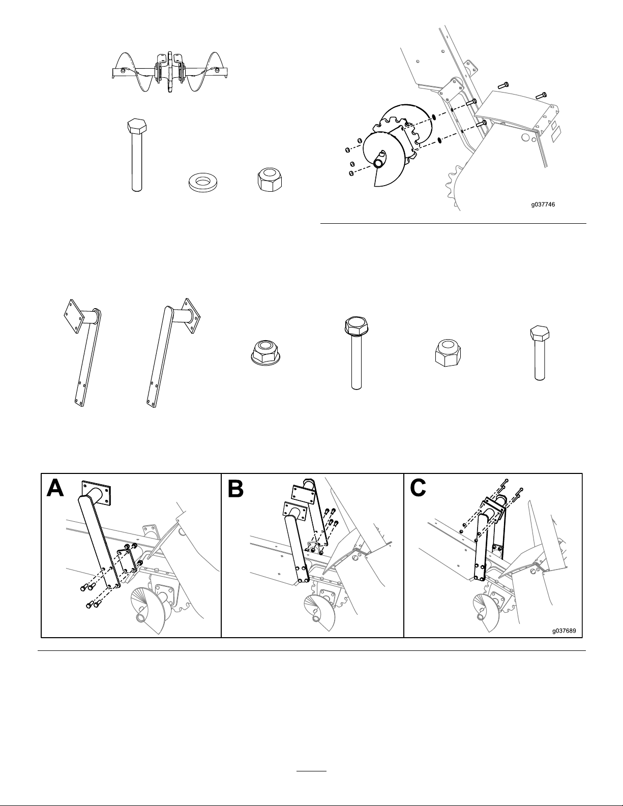
InstallingtheAuger
4x4x4x
(5/8x2
inches)
InstallingtheRestraint-BarBrackets
1x1x8x8x8x8x
(5/8inch)
(M12)
(M12x4-1/4
inches)
(5/8inch)
(5/8x2
inches)
6
Page 7
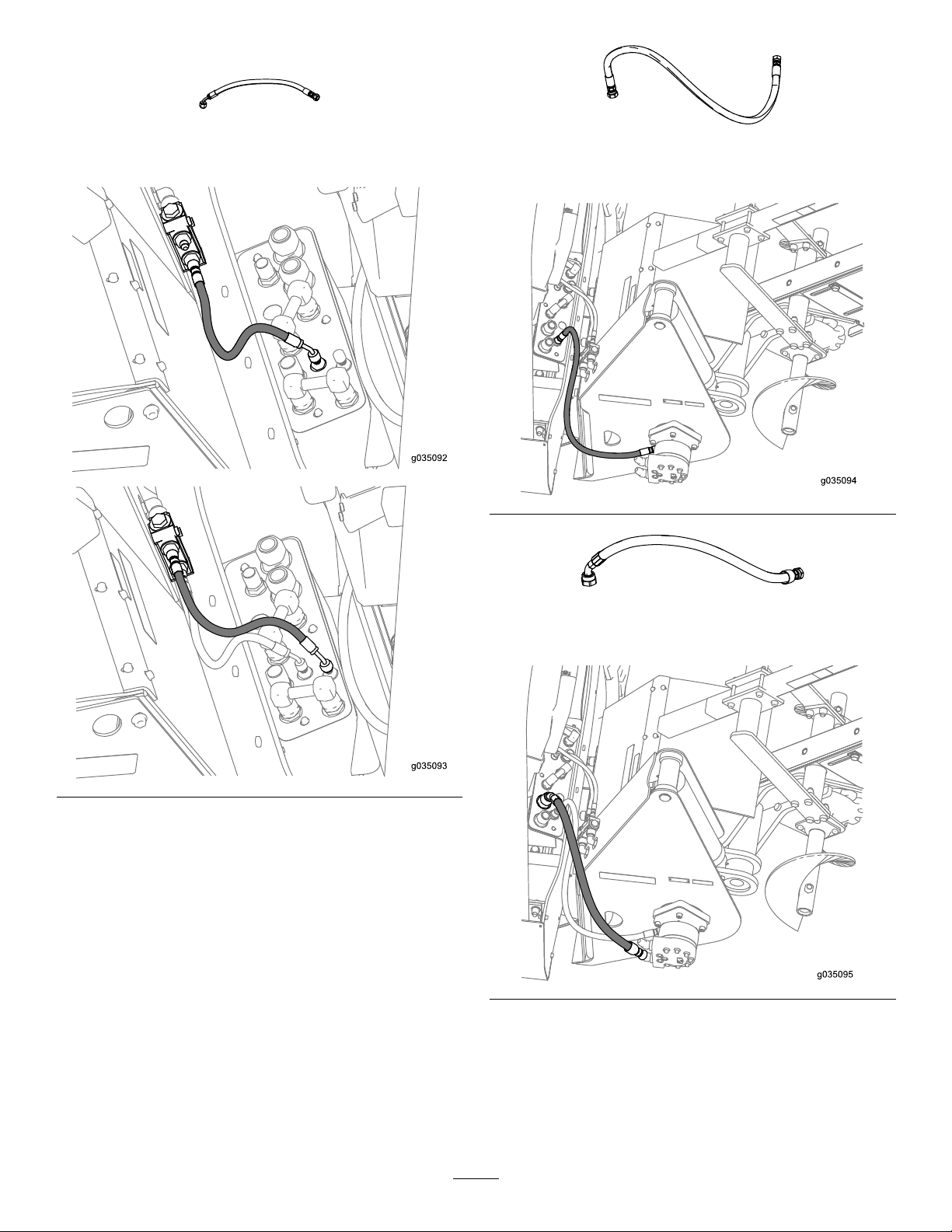
InstallingtheHydraulicHoses
2x
42cm(16-1/2inches)
1x
97cm(38inches)
88cm(34-1/2inches)
1x
7
Page 8
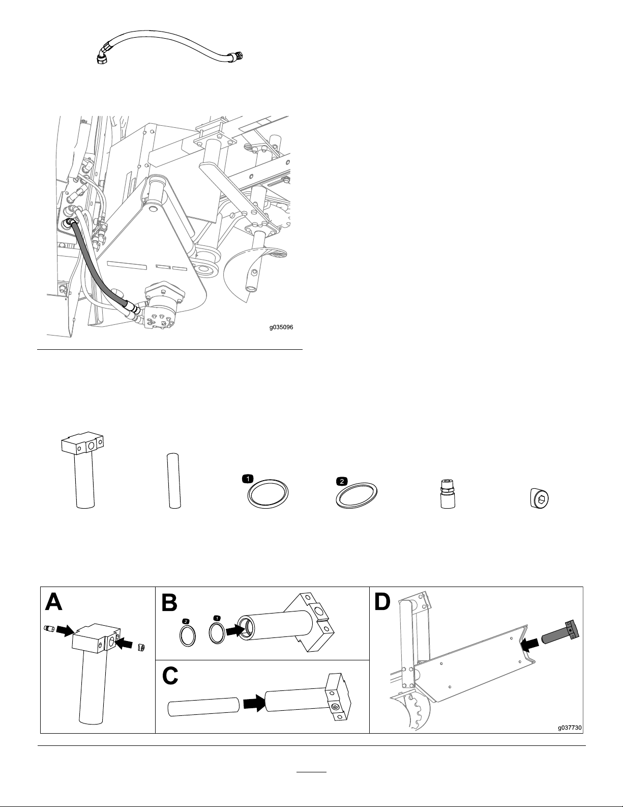
Testingthehoses
1.Startthemachine;refertothetractionunitOperator’s
Manual.
75cm(29-1/2inches)
1x
2.Operatethetrencher-chaindirectioncontrolandthe
attachmentcontrol(locatedontherightsideofthe
operatorseat)inbothdirectionsseveraltimestobleed
theairfromthehydraulicmotorandthehydrauliclift
cylinder.
Note:Thetrencher-chaindirectioncontrolrotatesthe
hubforwardandrearward,andtheattachmentcontrol
raisesandlowerstheboom-mounttting.Have
anotherpersonobservethehubandtheboom-mount
ttingastheymove.Moveeachofthecontrolsinboth
directionsuntilthehubandtheboom-mounttting
movesmoothlyinbothdirections.
InstallingtheBoom
AssemblingandInstallingtheBoom-EndCylinder
1x1x1x1x1x1x
O-ring
Washer
(3/16x1-3/4
inches)
8
Page 9
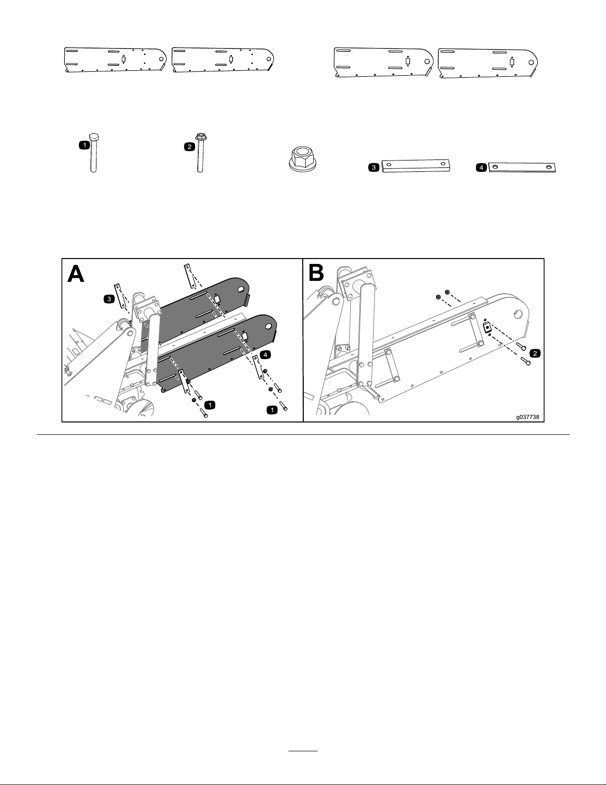
InstallingtheBoomPlates
2x2x
Longboomplates
4x2x2x2x2x
(5/8x4-1/2
inches)
Placethreadlockingadhesiveon4bolts(5/8x4-1/2inches)andinstallthemasshown.
(M12)(M12)
ThickbarclampThinbarclamp
Shortboomplates
9
Page 10

InstallingtheWearPadChannel
10x(shortboom)14x(longboom)
(M10)
Applythread-lockingadhesivetothebolts(M10)andsecurethewear-padchannelontotheboom.
Shortboomshown
1x
10
Page 11
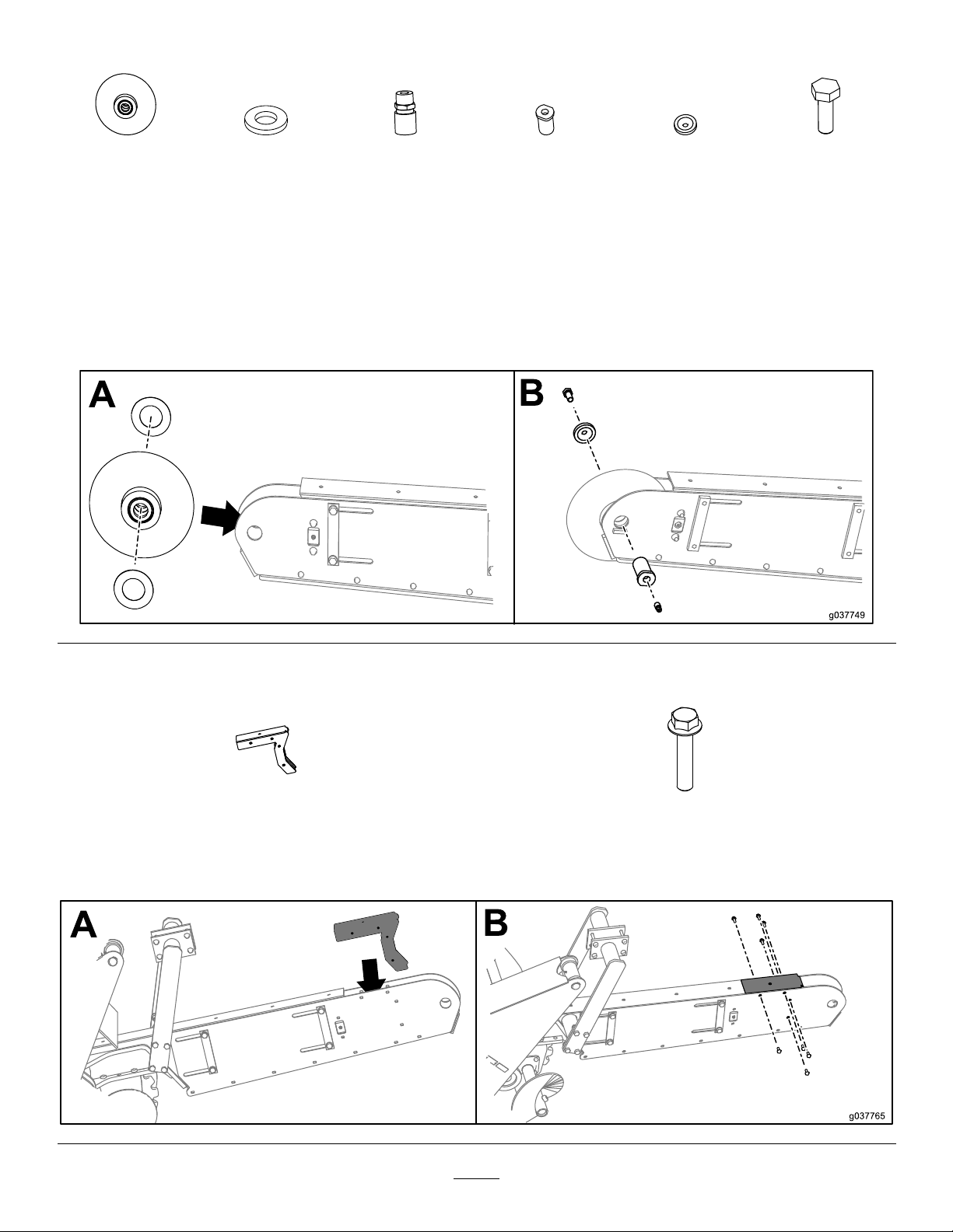
InstallingtheBoom-RollerAssembly
1x2x1x1x1x1x
1.Addgreasetothewashersandensurethatthewashersareushwiththerollersurfacewheninstalling.
2.Installtheboompinthroughtheboom-rollerassemblybeingcarefultocentertheconespacersbeforeslidingthe
pinthrough.
3.Applythread-lockingadhesivetotheboltandtorqueto230to258N∙m(170to190ft-lb).
4.Aftertheassemblyisinstalled,applygreasetotheboomendrollerslowlywhilerotatingtherolleruntilthegrease
ispurgedfromtheroller.
(3/4x1-1/2
inches)
InstallingtheShieldExtension(LongBoomOnly)
1x8x
(M10)
Applythread-lockingadhesivetothebolts(M10)andsecuretheshieldextensionontotheboomassembly.
11
Page 12
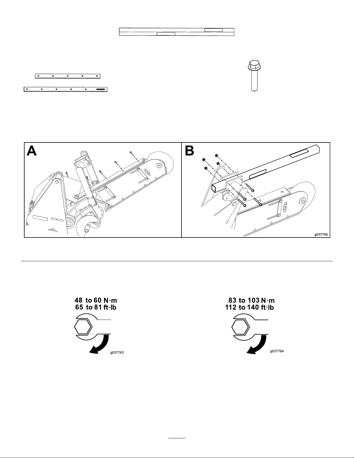
InstallingtheWearPadsandRestraintBar
1x
1x
Wearpad(shortand
longshown)
Applythread-lockingadhesivetothebolts(M10)andsecurethewearpadontotheboomassembly .
Shortboomshown
5x(shortboom)6x(longboom)
(M10)
TorquingtheHardware
Bolts(M10)Bolts(M12)
InstallingtheDiggingChain
RefertoInstallingtheDiggingChain(page24).
12
Page 13
Operation
1
G02191 1
SelectingtheProper ComponentsfortheTrencher
Usingthecorrecttrenchercomponentshelpstoincrease
thetrenchingspeedandextendingthelifeofthetrencher.
ContactanAuthorizedT oroServiceDealerformore
informationonpartsforyourtrencher.
SelectingtheProperChain
Itisimportanttohavethecorrectchainforthejob.The
soilconditionswilldeterminethetypeofchainthathasthe
strengthandtensionthatyouneed.Achainthatistoolight
wearsfastorbreaks;achainthatistooheavyincreasesthe
loadonthemachineandreducesthetrencherdiggingspeed;
however,aheavychainhasalongerwearlifethanalighter
chain.
Youcancongurethetrencherwithananti-backexdigging
chainthatisdesignedforharddiggingconditionsorawelded
H-platechainforextremeconditions.Thesideplatesofthe
anti-backexdiggingchainareclosetogether.Asthechain
leavesthesprocket,eachlinkcomestogetherandformsa
soliddiggingchannel.Thisactionkeepseachtoothatthe
correctdiggingangle.TheweldedH-platechainisfordigging
inthemostextremeconditions.
Important:Maintainthecorrectchaintension.Ifthe
chainistootightortooloose,thediggingefciency
decreasesandthepartswearmorequickly.Referto
CheckingtheChainTension(page18).
Note:Trencherchainsareratedbytheirtensilestrength;for
example,a34019kg(75,000lb)chaintakesaminimumof34
019kg(75,000lb)ofpulltobreakthechain.
Selectthechaintype;chooseeitheraanti-backexchainora
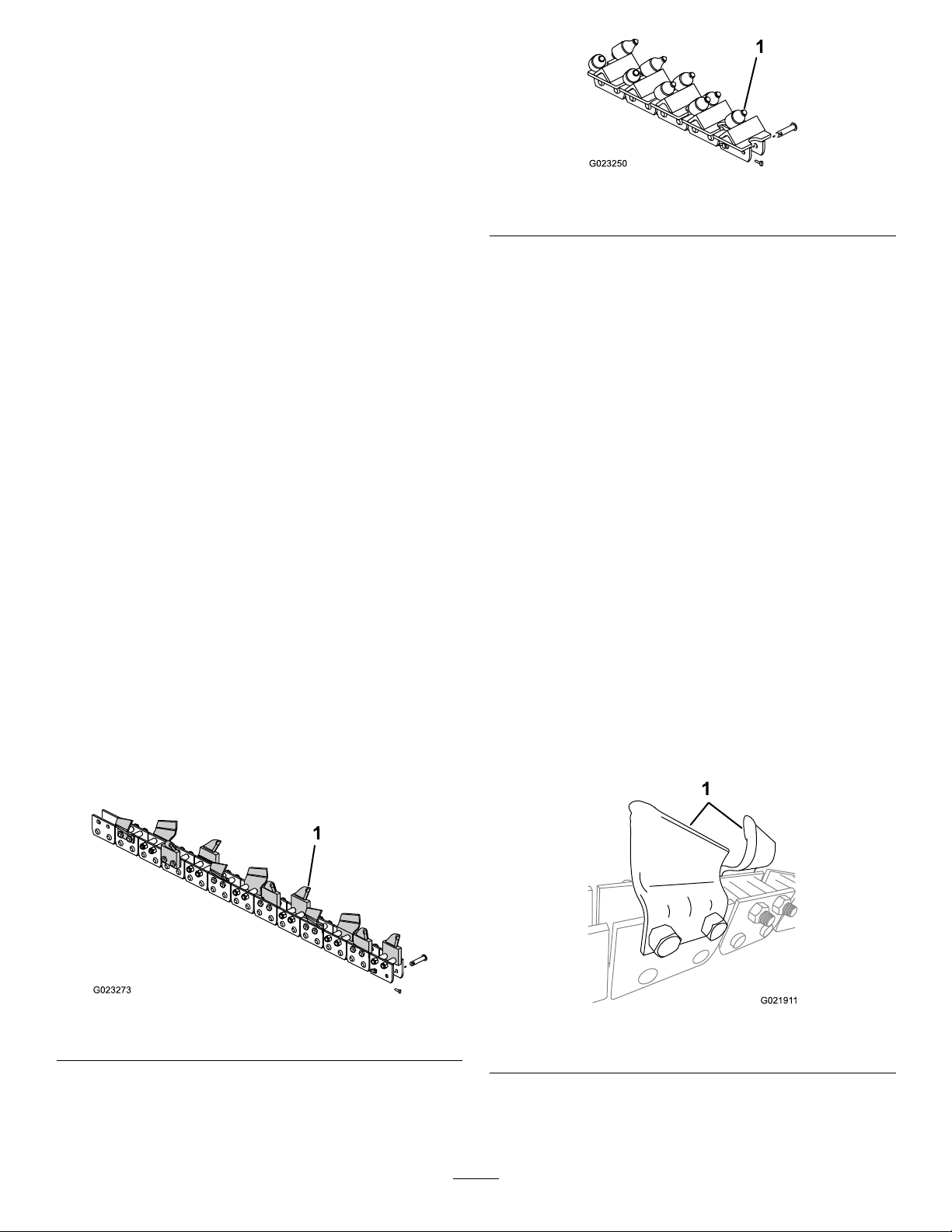
weldedH-platechain(Figure20andFigure21).
Figure21
1.H-platechain
SelectingtheProperDiggingTeeth
Themostimportantcomponentofthetrencherarethe
diggingteeth;thetypeofteeththatyouselectandthe
arrangementofteeththatyouusegreatlyaffectsthedigging
efciencyandtoothwear.
•Choosetheteethtype:
–cuppedteeth
–rock/frostbit
–sharkteeth
–cuppedteethandrock/frostbitcombination
–cuppedandsharkteethcombination
•Choosethetootharrangementwidth:
–152mm(6inch)
–203mm(8inch)
TypesofDiggingTeeth
Thetypesofdiggingteethareasfollows:
•Cuppedteeth(Figure22)arethebestforcutting
throughlighttomediumsoil.Thecuppeddesignofthe
toothcutsthroughthesoilandthenmovesitupandout
ofthetrench.
1.Anti-backexchain
Figure20
Figure22
1.Cuppedteeth
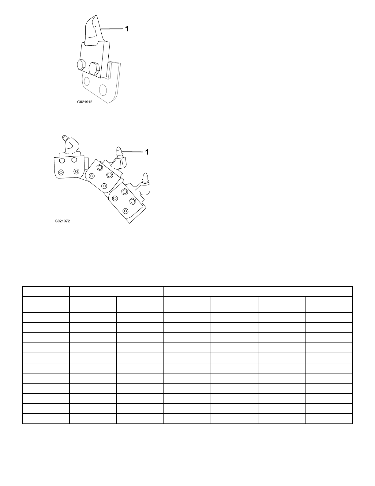
•Rockandfrostteeth(Figure23)orsharkteeth(Figure
24)arebestforcuttinggroundthatisveryhard,rocky,or
frozen;itisalsousedforcuttingthroughasphalt.
13
Page 14
G021912
1
1
G021972
Thearrangementofdiggingteethinvolvesbothwhereand
howeachtoothisattachedtothediggingchain.Usethe
followingguidelineswhenyouselectthearrangementsof
teeth:
•Installteeththatarethesamewidthandarespaced
equallyaroundthechain.
•Usefewerteethonthechainwhenyouareoperatingthe
trencherinwetclayorgumbo.
•Usemoreteethonthechainwhenyouareoperatingthe
trencherinsandyloamorrockyground.
Figure23
1.Sharktooth
Note:Youcanusedifferenttypesandcombinationsofteeth
toincreaseproductivityinvariousdiggingconditions.The
rockandfrostteethorthesharkteethpenetratethesoilwell,
andthecuppedteethhelptoremovethesoil.Tryseveral
combinationstodeterminetheonebestsuitedforyoursite.
Figure24
1.Rockandfrosttooth
ArrangementsoftheDiggingTeeth
CombinationsofBoom,Chain,andTeethforVariousSoilTypesandConditions
SoilTypeChainT ype
HeavyDuty
Anti-backex
Sand
SandyLoam
LooseShale
TopsoilX
Caliche(Hard)
Clay(Gumbo)
Coral
Rock(Loose)
AsphaltXXXX
HardClay
FrozenSoil
XXXXX
XX
XXXX
XXXX
XXXXX
XXXXX
H-Plate
CupCutterRock/Frost
X
X
XX
DiggingT eethT ype
MiningBit
Note:Youneedarockwheeltocutsolidrockorconcrete.
Shark
Mixed
14
Page 15
UsingtheTrencher
g021914
1
g021973
CheckingtheTooth-mountingBolts
ServiceInterval:Beforeeachuseordaily
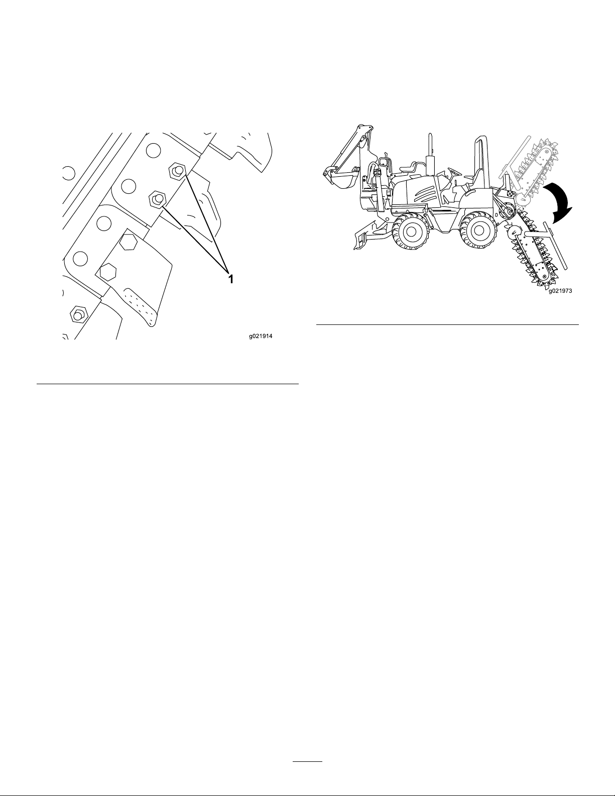
Checkthemountingboltsofallthechainteeth(Figure25),
andtightentheboltsasneeded.
PositioningtheBoomforTrenching
Forthebesttrenchingperformanceandthesmoothest
machineoperation,theboommustbeinthefulldown
trenchingposition(Figure26).Havingtheboominthis
positionpullsthemachinedownforbettertraction.The
grounddrivesimplypullsthetrencherteethintothefaceof
thetrench.
Figure26
Figure25
1.Mountingbolts
PositioningtheSeatforTrenching
Fastentheseatbeltandrotatetheseattothetrenching
position.
Note:Y oumustbeseatedintheoperator’sseatbefore
movingthemachine;otherwise,theenginestopsin1second.
UsingtheTrencherControls
•Movetherearattachmentspeedcontrolleverforwardto
actuatethediggingchainintheforwarddirection.
•Movetheleverfurtherforwardtoincreasethechain
speed.
•Movetheleverfurtherrearwardtodecreasethechain
speed.
MovethecontroltotheNEUTRALposition(A)tostop
thechain;movethecontrolleverrearward(B)toreverse
thechaindirection.
Whenyouraisetheboomfromthefulldownposition,the
trenchingloadpullsthemachinerearward.Thispulling
reducesthetractionandmaycausethemachinetobounce
andpullwhenthechaincontactsrootsorrocks.Therearward
pullofthetrenchingoperationalsoworksagainsttheground
drive,causingtheenginetoworkharder.
StartingaTrench
Important:Knowthelocationofallunderground
utilitiesbeforeoperatingthemachineontheworksite.
1.Ensurethatallpersonsareawayfromthemachine
beforeyoustarttheengineandwhileyouaretrenching.
2.Starttheengine;refertothetractionunitOperator’s
Manual.
3.Runtheengineat1/4throttleuntiltheenginereaches
theoperatingtemperature.
4.Movethecrumber(ifequipped)totheTransport
position(Figure27).
•Tolowerthetrencherboomtothedesireddepth,push
theattachmentcontrolleverawayfromyou;toraise
thetrencherboom,pullthecontrollevertowardyou.
Whenyoureleasethecontrollever,itwillreturntothe
NEUTRALpositionautomatically.
15
Page 16
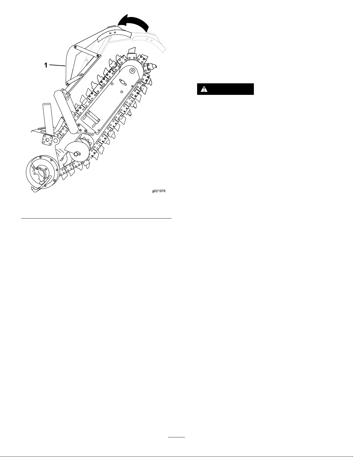
Figure27
1.Crumberbar(optional)
5.Whentheenginehasreachedtheoperating
temperature,movethemachinetotheworkareaand
positionthemachinetocutthetrench.
Note:Ensurethattheendofthetrencherboomis
severalfeetbeyondthestartingpointofthetrench.
6.Alignthemachinetothecenterlineofthenewtrench.
7.AdjusttheenginespeedtotheFullthrottleposition,
andlowertheboomtojustabovetheground.
8.Startthediggingchainbymovingtherearattachment
controllevertowardthefrontofthemachine.
Note:Youmustbeseatedintheoperatorseatbefore
movingthemachine;otherwise,theenginestopsin
1second.
Note:Thecrumber(ifequipped)automaticallymoves
fromtheTRANSPORTpositionintotheOPERATING
positionwhenthetrencherattachmentreachesthe
maximumdigdepth.
12.Decreasethediggingchainspeedandlookatthe
tachometer.
Note:Iftheenginespeedincreases,pushthe
utility-tractionleverforwarduntiltheenginespeedis
thesamethatinstep11.Repeatthissteptoobtain
thebesttrenchingspeed.
Note:Somehardsoilconditionsallowyoutodiga
trenchfasterbyreducingthechainspeed.
WARNING
Operatingatrencherattachmentwithouta
restraintbaroracrumbercouldresultinserver
personalinjuryordeathifthechainbreaks.
Donotoperateatrencherattachmentwithout
arestraintbar.
Note:Thetrencheroperatesbestwhentheengineis
atfullthrottle.Adjustthegroundspeedtokeepfrom
luggingtheengine.
Important:Allsteeringshouldbegradual.Donot
makesharpturnswiththeboomintheground.
Markingsharpturnswhilediggingwiththe
trencherwilldamagethetrencher.
Note:Checkthechaintensionwhenyouarestarting
anewtrenchineachlocation;refertoCheckingthe
ChainTension(page18).
CuttingaCurvedTrench
Important:Donotmakesharpturnswiththeboomin
theground.Markingsharpturnswhilediggingwiththe
trencherwilldamagethetrencher.
Youcanmakeagradualcurvebyusingtherear-wheelsteering
controlonlyasneededtoslightlyarticulatethemachine.Do
notmakesteeringcorrections,asthiswillswingtheboom
intothesideofthetrenchandundercutit.
StraighteningaCrookedTrench
Asthetrencherisdigging,itmayvaryslightlyfromastraight
line;thiscanoccurifyouarediggingtooquicklyforthesoil
conditions.Tostraightenthetrench,raisetheboom,reverse
thegroundtravelandmovethetrencherforwarduntilthe
diggingchainclearsthetrench.Correctthealignmentofthe
trenchertothetrenchandlowertheboom.
9.Movetheutility-tractionleverforwarduntilthe
machinestartstomoveforward.
10.Lowertheboomintotheground.
11.Whenthediggingchainisloweredtothedesireddepth,
movetheutility-tractionleverforwarduntiltheengine
speeddecreasesabout10%(200to300rpm).
Note:Rememberthatspeedonthetachometer.
FinishingtheTrench
1.Whenyoucompletethetrench,stopthemachine.
2.Slowlyraisetheboomuntilitisoutofthetrenchabout
15cm(6inches).
3.Movetheattachmentgroundspeedcontrollevertothe
NEUTRAL(disengaged)positiontostopthedigging
chain.
16
Page 17

4.PulltheattachmentliftleverbacktotheRAISEposition
untiltheboomisintheTRANSPORTposition.
5.MovethethrottletotheIDLEposition,shutoffthe
engine,andremovethekey.
OperatingTips
•Cleantheareaoftrash,branches,androcksbefore
trenchingtopreventdamagingtheequipment.
•Alwaysselecttheshortestboom,thelightestchain,and
thelightestteethtohandlethejob.Inharddigging
conditions,selectahightensile-strengthchain,arock
boom,andananti-backexchainwithrockandfrost
teeth.
•Alwaysbegintrenchingwiththeslowestgroundspeed
possible.Increasethetrenchingspeedifconditions
permit.Ifthechainspeedslowsdown,reducetheground
speedtokeepthechainmovingatitsfastestrate.Donot
spinthewheelswhiletrenching.
•Alwaysusefullthrottle(maximumenginespeed)when
trenching.
•Alwaystrenchwhilethemachineismovingintheforward
direction.
•Trenchwiththechainata45-to60-degreeanglefor
bestresults.
•Youcandigatrenchfasterbycontrollingthedepthand
adjustingtheboomperiodically .
•Ifthetrencherbindsinthesoil,reversethechain
direction.Oncethechainisloose,changechaindirections
andcontinuetrenching.
•Ifyouneedthenishedtrenchtobecleanerthanwhatis
possiblewiththetrencher,youcanpurchaseacrumber
fromanAuthorizedToroServiceDealer.Thecrumber,
whichmountsontotherestraintbar,scrapesthetrench
cleanasyoudig.
•Ifthediggingspeedofthetrencheristooslowortoo
fast,adjustit.
•Usethecorrectchainforthegroundconditions;referto
SelectingtheProperChain(page13).
•Toobtainmaximumdiggingefciencyfromthetrencher,
alwayskeepgoodsharpteethatthenecessaryspaces.As
teethbecomeworn,replacethemimmediately.
•Somegroundconditionsmayrequireafasterchainspeed.
Movethechainspeedcontrolfurtherforwardfromthe
NEUTRALposition.Youcanreducethelifeofthedigging
chainbyusingitathigherchainspeedsforanextended
time.
17
Page 18
Maintenance
GreasingtheTrencher
ServiceInterval:Every50hours
1.Cleanthegreasettingswitharag.
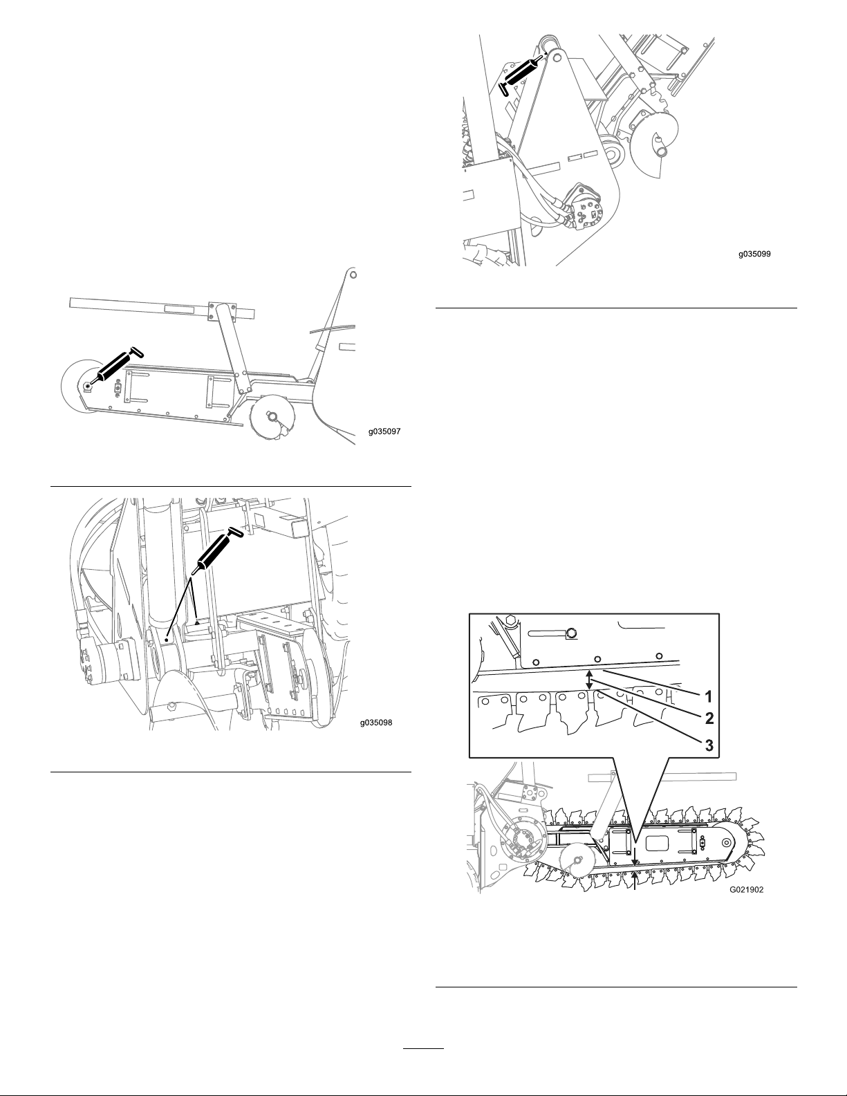
2.Connectthegreaseguntothegreasettingforthe
bearingofthelowerliftcylinder,andapply3pumpsof
greasetothettings(Figure28,Figure29,andFigure
30).
3.Wipeupanyexcessgrease.
Figure30
ServicingtheTrencherDigging Chain
CheckingtheChainTension
Figure28
Figure29
ServiceInterval:Aftertherst10hours
Beforeeachuseordaily
1.Starttheengine.
2.Makeatrenchabout3m(10ft)long.
3.Stopthetrencherchainandlifttheboomoutofthe
trench.
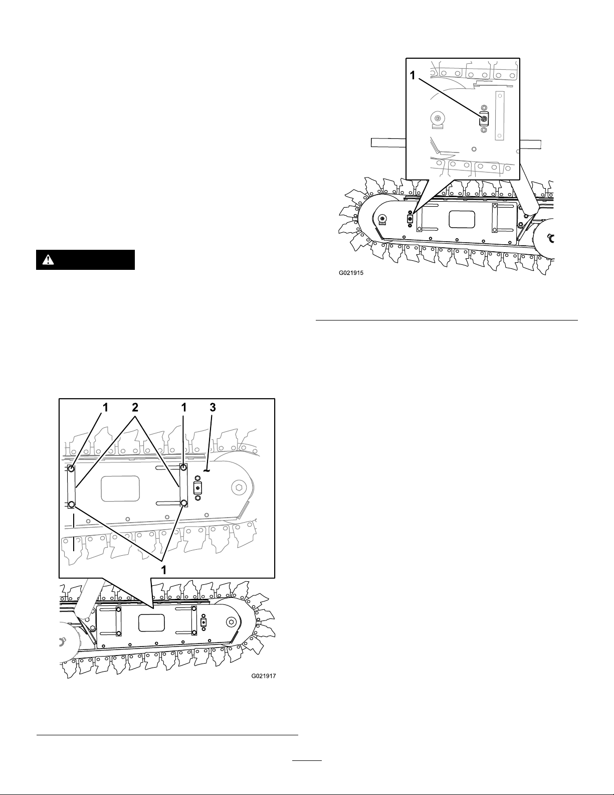
4.Movetheboomtothehorizontalposition(Figure31).
Figure31
1.Lowerwearstrip
2.51to76mm(2to3inch)
gap
5.Shutofftheengineandremovethekey.
18
3.Chain
Page 19
6.Measurethedistancebetweenthechainandthebottom
ofthelowerwearstrip(Figure31).
•Ifthegapbetweenthelowerwearstripandthe
chainis51to76mm(2to3inch),thechaintension
iscorrect(Figure31).
•Ifthegapissmallerthat51mm(2inch),thechain
tensiontootight;refertoDecreasingtheChain
Tension(page19).
•Ifthegapislargerthat76mm(3inch),thechain
tensiontooloose;refertoIncreasingtheChain
Tension(page20).
Note:Thechaintensionhasasignicantaffecton
theproductivityofthemachine;setthechaintension
aslooseaspossible.
DecreasingtheChainTension
WARNING
2.Locatethebleedplug(hex-socket)atthesideplateon
therightsideoftheboom(Figure33).
Ifyouremovethegreasettingfromtheboom
beforeyoureleasethepressureinthesystem,
personalinjurymayresult.
Beforeremovingthegreasetting,loosen(butdo
notremove)theplugontheoppositesideofthe
boom.
1.Attheleftsideoftheboom,loosenthe4boltsthat
securethelockbarsandthesideplates(Figure32).
Figure33
1.Bleedplug
3.Slowlyrotatethebleedplugcounterclockwise2or3
revolutions,andallowthegreasetoowfromaround
theplug(Figure33).
Note:Thechaintensionwilldecreaseasthegap
betweenthechainandthewearstripincreases.
4.Whenyouachievea51to76mm(2to3inch)gap
betweenthechainandthewearstrip,tightentheplug
(Figure32andFigure33).
5.Torquethe4bolts(Figure32)thatsecurethelockbars
andthesideplatesto190to215N-m(140to159ft-lb).
6.PerformthestepsinCheckingtheChainTension(page
18).
1.Bolt
2.Lockbars
Figure32
3.Sideplate
19
Page 20
IncreasingtheChainTension
g0359 03
2.Cleantheareaaroundthedustcapwithacleaning
solvent(Figure34).
WARNING
Ifyouremovethegreasettingfromtheboom
beforeyoureleasethepressureinthesystem,
personalinjurymayresult.
Beforeremovingthegreasetting,loosen(butdo
notremove)theplugontheoppositesideofthe
boom.
GreaseType:Lithium-basedgrease
1.Locatethecapforthegreasettingatthesideplateon
theleftsideoftheboom(Figure34).
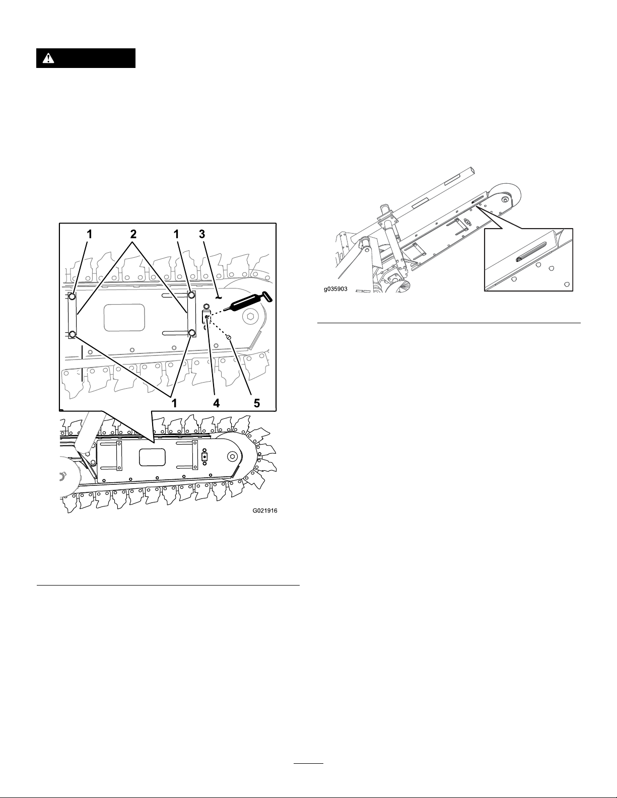
3.Useaneedle-noseplierstorotatethedustcap
counterclockwiseandremovethecapfromthegrease
tting(Figure34).
4.Loosentheboltsthatsecurethelockbarsandtheside
platesontheleftsideoftheboom(Figure32).
•4boltsfortheshortboom(Figure34)
•5boltsforthelargeboom(Figure35)
Figure35
5.Connectagreasegunwiththespeciedgreasetothe
greasetting.
Figure34
1.Bolt
2.Lockbar5.Dustcap
3.Sideplate
4.Greasetting
6.Whileobservingthechaingap,pumpthegreasegun
untilthegapbetweenthewearstripandthechainis51
to76mm(2to3inches);refertoFigure31.
7.Removethegreasegunfromthettingandinstallthe
dustcap.
8.Torquethe4bolts(Figure32)thatsecurethelockbars
andthesideplatesto190to215N-m(140to159ft-lb).
9.PerformthestepsinCheckingtheChainTension(page
18).
20
Page 21
TorquingtheFastenersontheChain
DriveSprocket
CheckingtheTrencherChainWear
StripandWearChannel
ServiceInterval:Aftertherst10hours
Aftertherst25hours
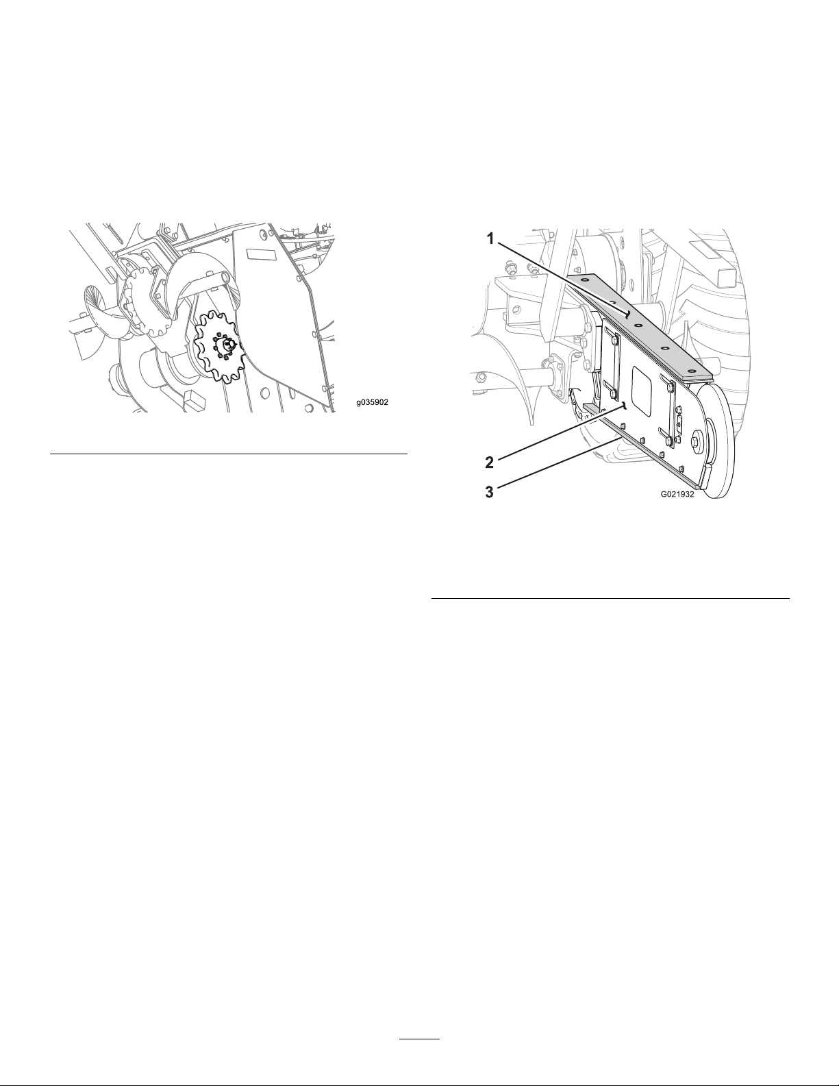
Torquethe8studsandnutsthatsecurethesprocketforthe
diggingchaintotheplanetarydrivehousingto109to314
N∙m(81to99ft-lb);referto(Figure36).
Note:Thetorquespecicationsarefordrythreadsonly.
Figure36
ServiceInterval:Beforeeachuseordaily
1.Liftthechainatthewearstripatthetopoftheboom,
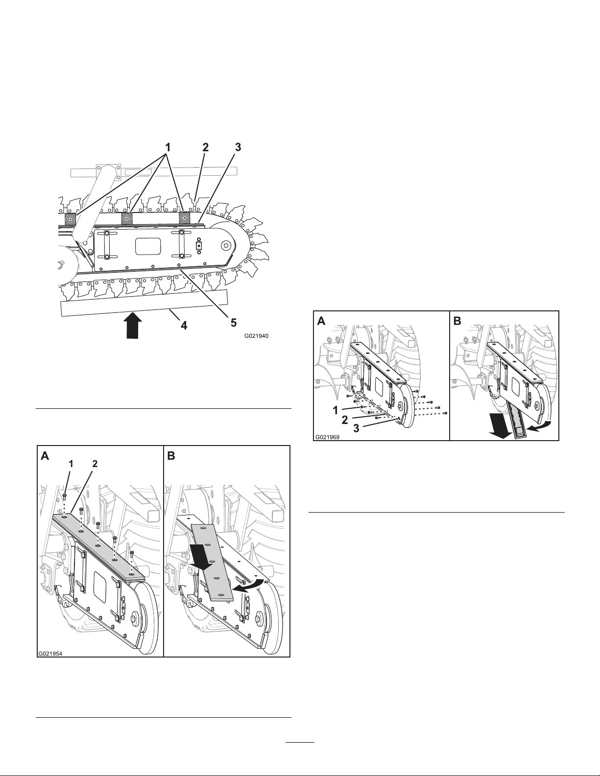
andcheckthewearstripforsignsofdamageor
excessivewear(Figure37).
Note:Ifthewearstripiswornthroughtotheframe
oftheboom,replacethewearstrip;refertoReplacing
theTrencherChainWearStrip(page22).
Figure37
Thediggingchainhasbeenremovedforclarity.
1.Wearstrip3.Wearchannel
2.Boom
2.Checkthewearchannelatthebottomoftheboomfor
signsofdamageandexcessivewear(Figure37).
Note:Ifthewearchanneliswornthroughtothe
bracketofthechannel,replacethewearchannel;refer
toReplacingtheTrencherWearChannel(page22).
21
Page 22
ReplacingtheTrencherChainWear
Strip
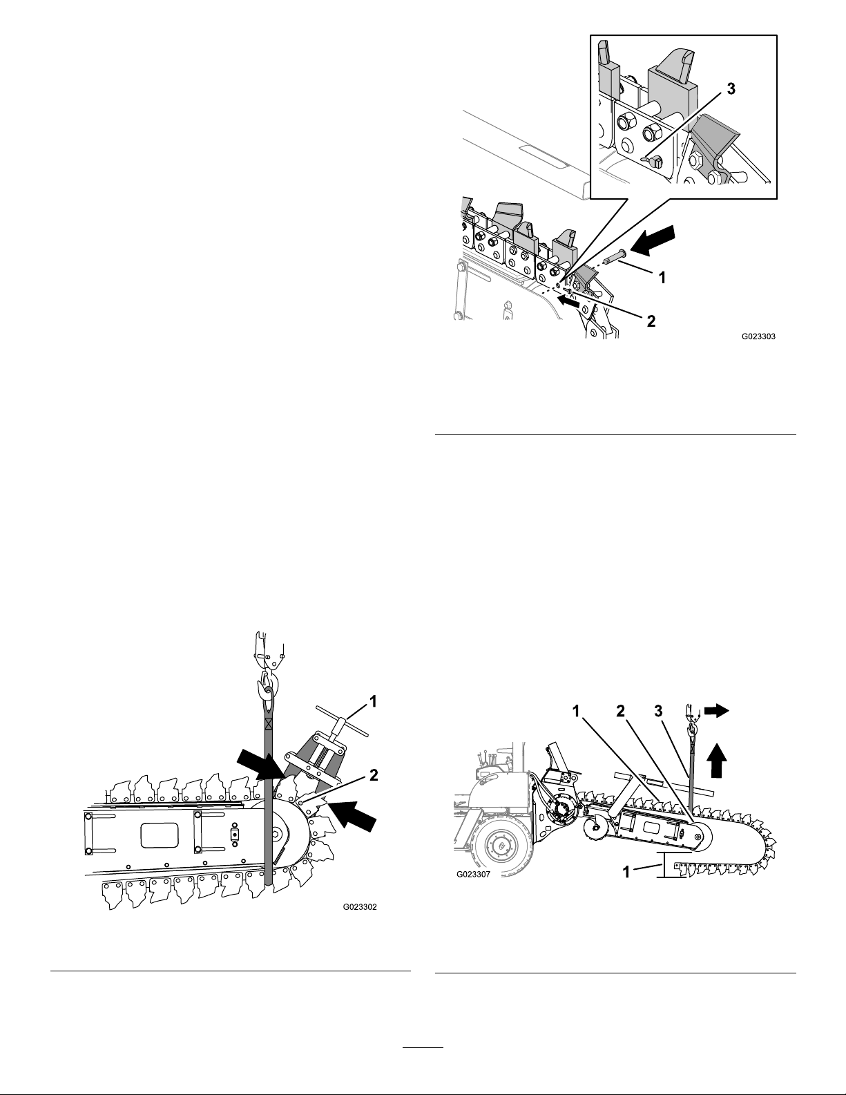
1.Loosenthetrencherchain;refertoDecreasingthe
ChainTension(page19).
2.Liftthechainatthetopoftheboom,andinstallblocks
betweenthechainandtheboom(Figure38).
Note:Supportingthechainatthebottomofthe
boomhelpsbyliftingthechainabovethewearstrip.
4.Removethewearstrip(Figure39).
5.Cleanthethreadsofthebolts.
6.Applymedium-grade(serviceremovable)
thread-lockingcompoundtothethreadsofthebolts.
7.Aligntheholesofthenewwearstripwiththeholesin
thetopoftheboom(Figure39).
8.Securethewearstriptothetopoftheboomwiththe
boltsthatyoupreviouslyremoved(Figure39).
9.Removethewoodblocksandlowerthechainontothe
boom.
10.Adjustthechaintensionofthetrencher;referto
CheckingtheChainTension(page18).
ReplacingtheTrencherWearChannel
1.Loosenthetrencherchain;refertoDecreasingthe
ChainTension(page19).
2.Removethe10boltsthatsecurethewearchannelto
thebottomleftandbottomrightsidesoftheboom
(Figure40).
Figure38
1.Blocks
2.Diggingchain5.Wearchannel
3.Wearstrip
4.Support
3.Removethe5boltsthatsecurethewearstriptothetop
oftheboom(Figure39).
Figure40
Thediggingchainhasbeenremovedforclarity.
1.Bolt3.Boom
2.Wearstrip
3.Removethetrencherwearchannel(Figure40).
4.Cleanthethreadsofthebolts.
5.Applymedium-grade(serviceremovable)
thread-lockingcompoundtothethreadsofthebolts.
6.Aligntheholesofthenewwearchannelwiththeholes
inthebottomleftandbottomrightsidesoftheboom
(Figure40).
Figure39
Thediggingchainhasbeenremovedforclarity.
1.Bolt2.Wearstrip
7.Securethewearchanneltothebottomoftheboom
withtheboltsthatyoupreviouslyremoved(Figure40).
8.Adjustthechaintensionofthetrencher;referto
CheckingtheChainTension(page18).
22
Page 23
ReplacingtheDiggingChain
RemovingtheDiggingChain
PreparingtoRemovetheDiggingChain
1.Startthemachineandmovetheboomtothefullup
position.
2.Rotatethediggingchainuntilthemasterpinis
positionedatthetopoftheidlerwheeloftheboom
(Figure42).
3.Turnthemachineoff,andremovethekey.
4.Removethebleedplugfromthechaintensionerofthe
boom;refertoCheckingtheChainTension(page18).
Note:Theidlerwheeloftheboomshouldmove
forwardanddownasthechaintensiondecreases.
5.Installthebleedcap.
6.Startthemachine,movetheboomtothehorizontal
position,turnthemachineoffandremovethekey.
RemovingtheMasterPinintheDiggingChain
1.Countingfromthemasterpin,looptheliftingstrap
aroundthechainatthediggingtoothofthefthor
sixthlinkbelowandforwardoftheidlerwheel(Figure
41).
2.Withthestrapattachedtotheliftingequipment,raise
theliftingstrapenoughtosupportthediggingchain.
3.Clamptheendsofthechainwithawithachainclamp
atthelinkrollersateithersideoftheinnerandouter
platesatthemasterpin(Figure41).
Figure42
1.Masterpin
2.Safetypin
3.Safetypin(bent30°to
45°)
Note:Discardthesafetypin.
5.Removethemasterpinandtherollerforthemaster
pin(Figure42).
Note:Retainthemasterpinandtherollerfor
installingthereplacementchain.
RemovingtheDiggingChainfromtheMachine
1.Lowertheliftingequipmentuntiltheendofthedigging
chainislayingontheground(Figure46).
2.Removetheliftingstrap.
3.Startthemachineandlowertheboomuntilthebottom
idlerwheelispositioned31to36cm(12to14inches)
abovetheground(Figure43).
Figure41
1.Chainclamp
2.Masterpinhole
4.Straightenorcutoffthetailofthesafetypinand
removethepin(Figure42).
Figure43
1.Diggingchain
2.Idlerwheel
3.Liftingstrap
4.Clearance31to36cm(12
4.Startthemachineandmovethetrencherdrivecontrol
totheslowforwardchainspeedposition.
23
to14inches)
Page 24
5.Whenthediggingchainhasclearedthedrivesprocket,
movethetrencherdrivecontroltotheNEUTRAL
position,turnthemachineoff,andremovethekey
(Figure43).
6.Wraptheliftingstraparoundthediggingchainat
theidlerwheel,andattachthestraptothelifting
equipment(Figure43).
7.Raisetheliftingequipmentandremovethedigging
chainfromtheboom(Figure43).
InstallingtheDiggingChain
PreparingtoInstalltheDiggingChain
1.Startthemachineandmovetheboomtothefullup
position.
2.Settheparkingbrake,turnthemachineoff,and
removethekey.
3.Removethebleedplugfromthechaintensionerofthe
boom;refertoCheckingtheChainTension(page18).
4.Movetheidlerwheeloftheboomforwardanddown.
5.Installthebleedcap.
AligningtheDiggingChain
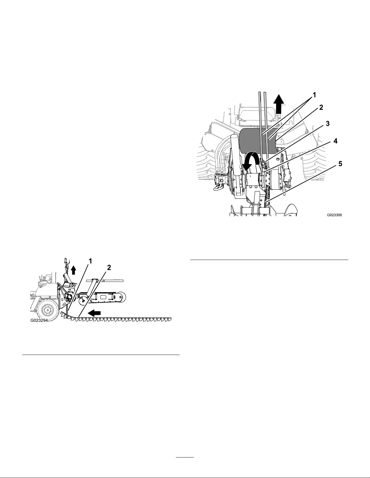
Thisprocedurerequires2peopletoalignthediggingchainto
themachine.
1.Routetheendsoftheliftingstrapforwardofthe
sprockethub,oneithersideofthedrivesprocket,and
uppastthedirtdeector(Figure45).
Note:Movethedirtdeectorupandawayfromthe
liftingstrap.
6.Startthemachine,movetheboomtothehorizontal
position,turnthemachineoff,andremovethekey.
7.Laythediggingchainonthegroundinastraightline,
belowtheliftingequipmentsuchasahoist,andwith
thecuttingfaceoftheteethpointingtowardthepath
whereyouwillmovethemachine(forward)toposition
itoverthediggingchain(Figure44).
Figure44
1.Liftingstrap2.Diggingchain(teethdown
andforward)
8.Attheforwardendofthechain,loopa3.65m(12
foot)liftingstrapwithaliftingcapacityof181.4kg
(400lb)aroundthechainatthediggingtoothofthe
thirdorfourthlinkofthechain(Figure44).
9.Startthemachineandpositionitwithtrencheroverthe
diggingchainandwiththeliftingstrapforwardofthe
drivesprocketofthetrencher(Figure44).
Note:Whenpositionedcorrectly,theboomofthe
trencherisalignedwiththediggingchain.
Figure45
1.Liftingstrap
2.Dirtdeector
3.Diggingchain
4.Drivesprocket
5.Upperwearstrip
2.Connecttheendsoftheliftingstraptothelifting
equipment,andraisetheendofthechainuntilthe
drivepinsengagethedrivesprocket(Figure45).
3.Startthemachineandmovethetrencherdrivecontrol
totheslowforwardchainspeedposition.
Important:Ifthechainisnotalignedorengaged
withthedrivesprocket,turnthemachineoff,
removethekey,andalignthechaintothedrive
sprocket.
Note:Themachinedrivesthechainontotheupper
wearstripoftheboom.
Note:Maintaintensiononthestrapuntiltheendof
thechainisontheupperwearstrip.
4.Lowertheliftingstrapasthechainmovesaroundthe
sprocketandintopositionontheupperwearstrip.
5.MovethetrencherdrivecontroltotheNEUTRAL
positionwhentheendofthechainispositionedontop
oftheidlerwheeloftheboom(Figure46).
10.Turnthemachineoffandremovethekey .
24
Page 25
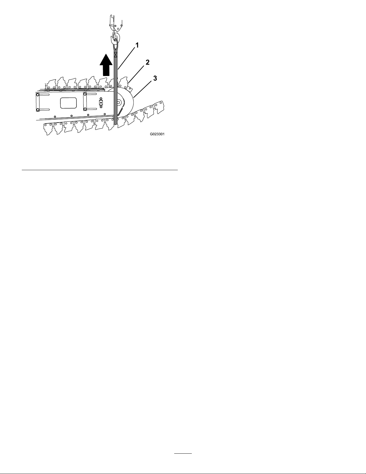
Figure46
1.Liftingstrap
2.Diggingchain
6.Shutoffthemachineandremovethekey.
7.Removetheliftingstrapfromthemachine.
3.Idlerwheel
Storage
1.Beforestoringthemachine,brushoffthedirtfrom
theattachment.
2.Checktheconditionofthediggingchain.Adjustand
lubricatethechain.Replaceanywornordamaged
parts.
3.Checkandtightenallbolts,nuts,andscrews.Repairor
replaceanypartthatisdamagedorworn.
4.Ensurethatallhydrauliccouplersareconnected
togethertopreventcontaminatingthehydraulicsystem.
5.Paintallscratchedorbaremetalsurfaceswithpaint
availablefromanAuthorizedServiceDealer.
6.Storetheattachmentinaclean,drygarageorstorage
area.Coverthetrenchertoprotectitandkeepitclean.
LinkingtheDiggingChain
1.Attheendofthechainlayingontheground,loopthe
liftingstraparoundthechainatthediggingtoothof
thefthorsixthlinkofthechain(Figure46).
2.Raisethechainandpositionitaroundtheidlerwheel
(Figure46andFigure41).
Note:Rotatetheaugerasnecessarytoengagethe
teethofaugerdrivesprocketwiththediggingchain.
3.Clamptheendsofthechainwithawithachainclamp
atthelinkrollersateithersideoftheinnerandouter
platesatthemasterpin(Figure41).
4.Aligntheholeofalinkrollerwiththeholesintheinner
platesattheendofthechain(Figure42).
5.Aligntheholesintheinnerplatesandtherollerofthe
chainwiththeholesintheouterplatesoftheotherend
ofthechain(Figure42).
6.Alignthemasterpinwiththeholeinthepinparallel
withthechainplatesforwardoftheidlerwheel(Figure
42).
7.Insertthemasterpinthroughthediggingchainplates.
8.Insertthesafetypinthroughthemasterpinwiththe
headofthepintowardtheidlerwheel(Figure42).
Important:Donotinstallausedsafetypin.Only
useanewsafetypin.
9.Removetheliftingstrapandthechainclamp.
10.Bendthetailofthesafetypindown30°to45°(Figure
42).
11.Adjustthetensionofthediggingchain;referto
CheckingtheChainTension(page18).
25
Page 26

Troubleshooting
Problem
Thechaindoesnotturn.
Thetrencherdoesnotdigfastenough.
Thechainturnsinthewrongdirection.1.Thehydraulichosesarereversed.1.Disconnectthereversedhosesand
1.Ahydraulicttingisnotcompletely
connected.
2.Ahydraulicttingisdamaged.2.Replacethedamagedtting.
3.Thereisanobstructioninahydraulic
hose.
4.Anauxiliaryvalveonthemachineis
notopening.
5.Theboom-endbearinghasfailed.
6.Thediggingchainistootight.6.Adjustthetensiononthediggingchain.
7.Thereissandbuildupinthetoothroot
ofthedrivesprocket.
8.Thehydraulicmotororthechaindrive
hasfailed.
1.Theteethareworn.1.Replaceanywornteeth.
2.Thereisarestrictioninahydraulic
hose.
3.Thehydraulicsystemistoohot.
4.Thereliefvalveissetbelow
specications.
PossibleCauseCorrectiveAction
1.Checkandtightenallttings.
3.Findandremovetheobstruction.
4.Repairthevalve.
5.Replacethebearing.
7.Raisethetrencher,runthechain
backward,thendecreasethechain
tension.
8.ContactanAuthorizedServiceDealer.
2.Checkthehosesandrepairany
problemsfound.
3.Shutdownthesystemandallowitto
cool.
4.ContactanAuthorizedServiceDealer.
installthemcorrectly .
Thebearing-caselubeiscontaminated.
1.Thellplugisleaking.1.Ifthereismoisturearoundthewheel
plug,changetheoilandreplacethe
plugandtheplugO-ring.
2.TheO-ringonthemotorhasfailed.2.ContactanAuthorizedServiceDealer.
3.Thesealhasfailed.3.ContactanAuthorizedServiceDealer.
26
Page 27

Notes:
Page 28

TheT oroWarranty
ALimitedWarranty
Underground
Equipment
ConditionsandProductsCovered
TheToroCompanyanditsafliate,T oroWarrantyCompany,pursuant
toanagreementbetweenthem,jointlywarrantyourToroUnderground
Equipment(“Product”)tobefreefromdefectsinmaterialsorworkmanship.
Whereawarrantableconditionexists,wewillrepairtheProduct
atnocosttoyouincludingdiagnostics,labor,andparts.
ThefollowingwarrantyappliesfromthedatetheProductisdeliveredtothe
originalretailpurchaserorrentalowner.
ProductsWarrantyPeriod
EnginePoweredUnits&FluidMixers
AllSerializedAttachments
RockHammer6months
Engines
1yearor1000operatinghours,
whicheveroccursrst
1year
Throughenginemanufacturers:
2yearsor2000operatinghours,
whicheveroccursrst
InstructionsforObtainingWarrantyService
YouareresponsiblefornotifyingtheUndergroundDealerfromwhomyou
purchasedtheProductassoonasyoubelieveawarrantablecondition
exists.IfyouneedhelplocatingaUndergroundDealer ,orifyouhave
questionsregardingyourwarrantyrightsorresponsibilities,youmay
contactusat:
ToroCustomerCare
ToroWarrantyCompany
811 1LyndaleAvenueSouth
Bloomington,MN55420-1196
TollFreeat855-493-0088(U.S.Customers)
1-952-948-4318(InternationalCustomers)
OwnerResponsibilities
AstheProductowner,youareresponsibleforrequiredmaintenanceand
adjustmentsstatedinyourOperator'sManual.Failuretoperformrequired
maintenanceandadjustmentscanbegroundsfordisallowingawarranty
claim.
ItemsandConditionsNotCovered
Notallproductfailuresormalfunctionsthatoccurduringthewarranty
periodaredefectsinmaterialsorworkmanship.Thiswarrantydoesnot
coverthefollowing:
•Productfailureswhichresultfromtheuseofnon-T ororeplacement
parts,orfrominstallationanduseofadd-on,ormodiednon-Toro
brandedaccessoriesandproducts.Aseparatewarrantymaybe
providedbythemanufactureroftheseitems.
•Productfailureswhichresultfromfailuretoperformrecommended
maintenanceand/oradjustments.Failuretoproperlymaintainyour
ToroproductpertheRecommendedMaintenancelistedinthe
Operator’sManualcanresultinclaimsforwarrantybeingdenied.
•ProductfailureswhichresultfromoperatingtheProductinanabusive,
negligent,orrecklessmanner.
•Partssubjecttoconsumptionthroughuseunlessfoundtobedefective.
Examplesofpartswhichareconsumed,orusedup,duringnormal
Productoperationinclude,butarenotlimitedto:brakes,lters,lights,
bulbs,belts,tracksortires,diggingteeth,diggingbooms,digging,
drive,ortrackchains,trackpads,drivesprockets,idlers,rollers,
blades,cuttingedges,orothergroundengagingcomponents.
•Failurescausedbyoutsideinuence.Conditionsconsideredtobe
outsideinuenceinclude,butarenotlimitedto,weather,storage
practices,contamination,useofunapprovedfuels,coolants,lubricants,
additives,water,orchemicals,etc.
•Failureorperformanceissuesduetotheuseoffuels(e.g.gasoline,
diesel,orbiodiesel)thatdonotconformtotheirrespectiveindustry
standards.
•Normalnoise,vibration,wearandtear ,anddeterioration.
•Normal“wearandtear”includes,butisnotlimitedto,damagetoseats
duetowearorabrasion,wornpaintedsurfaces,scratcheddecals,etc.
•Haulingexpenses,traveltime,mileage,orovertimeassociatedwith
transportingproducttotheauthorizedT orodealer.
Parts
Partsscheduledforreplacementasrequiredmaintenanceinthe
Operator’sManual,arewarrantedfortheperiodoftimeuptothescheduled
replacementtimeforthatpart.Partsreplacedunderthiswarrantyare
coveredforthedurationoftheoriginalproductwarrantyandbecomethe
propertyofT oro.T orowillmakethenaldecisionwhethertorepairany
existingpartorassemblyorreplaceit.Toromayuseremanufacturedparts
forwarrantyrepairs.
MaintenanceisatOwner’sExpense
Enginetune-up,lubrication,cleaningandpolishing,replacementoflters,
coolant,andcompletingrecommendedmaintenancearesomeofthe
normalservicesT oroproductsrequirethatareattheowner’sexpense.
GeneralConditions
RepairbyanAuthorizedToroUndergroundDealerisyoursoleremedy
underthiswarranty.
NeitherTheToroCompanynorToroWarrantyCompanyisliablefor
indirect,incidentalorconsequentialdamagesinconnectionwiththe
useoftheToroProductscoveredbythiswarranty,includingany
costorexpenseofprovidingsubstituteequipmentorserviceduring
reasonableperiodsofmalfunctionornon-usependingcompletion
ofrepairsunderthiswarranty.ExceptfortheEmissionswarranty
referencedbelow,ifapplicable,thereisnootherexpresswarranty.All
impliedwarrantiesofmerchantabilityandtnessforusearelimitedto
thedurationofthisexpresswarranty.
Somestatesdonotallowexclusionsofincidentalorconsequential
damages,orlimitationsonhowlonganimpliedwarrantylasts,sotheabove
exclusionsandlimitationsmaynotapplytoyou.Thiswarrantygivesyou
speciclegalrights,andyoumayalsohaveotherrightswhichvaryfrom
statetostate.
Noteregardingenginewarranty:
TheEmissionsControlSystemonyourProductmaybecoveredby
aseparatewarrantymeetingrequirementsestablishedbytheU.S.
EnvironmentalProtectionAgency(EP A)and/ortheCaliforniaAirResources
Board(CARB).Thehourlimitationssetforthabovedonotapplytothe
EmissionsControlSystemWarranty.RefertotheEngineEmissionControl
WarrantyStatementsuppliedwithyourproductorcontainedintheengine
manufacturer’sdocumentationfordetails.
CountriesOtherthantheUnitedStatesorCanada
CustomerswhohavepurchasedT oroproductsexportedfromtheUnitedStatesorCanadashouldcontacttheirT oroDistributor(Dealer)toobtain
guaranteepoliciesforyourcountry ,province,orstate.IfforanyreasonyouaredissatisedwithyourUndergroundDealer’sserviceorhavedifculty
obtainingguaranteeinformation,contacttheToroimporter.
AustralianConsumerLaw:AustraliancustomerswillnddetailsrelatingtotheAustralianConsumerLaweitherinsidetheboxoratyourlocalT oro
Dealer.
374-0292RevC
 Loading...