

Page 1

FormNo.3398-974RevA
TimeCutter
®
MX5050Riding
Mower
ModelNo.74770—SerialNo.316000001andUp
Registeratwww.T oro.com.
OriginalInstructions(EN)
*3398-974*A
Page 2
WARNING
G014523
1
CALIFORNIA
Proposition65Warning
Thisproductcontainsachemicalorchemicals
knowntotheStateofCaliforniatocausecancer,
birthdefects,orotherreproductiveharm.
Theengineexhaustfromthisproduct
containschemicalsknowntotheStateof
Californiatocausecancer,birthdefects,
orotherreproductiveharm.
ThissparkignitionsystemcomplieswithCanadianICES-002
CustomerServiceandhavethemodelandserialnumbersof
yourproductready.Figure1identiesthelocationofthe
modelandserialnumbersontheproduct.Writethenumbers
inthespaceprovided.
ItisaviolationofCaliforniaPublicResourceCode
Section4442or4443touseoroperatetheengineonany
forest-covered,brush-covered,orgrass-coveredlandunless
theengineisequippedwithasparkarrester,asdenedin
Section4442,maintainedineffectiveworkingorderorthe
engineisconstructed,equipped,andmaintainedforthe
preventionofre.
Theenclosed
Engine Owner's Man ual
issuppliedfor
informationregardingtheUSEnvironmentalProtection
Agency(EPA)andtheCaliforniaEmissionControl
Regulationofemissionsystems,maintenance,and
warranty.Replacementsmaybeorderedthroughthe
enginemanufacturer.
Formodelswithstatedenginehorsepower,thegross
horsepoweroftheenginewaslaboratoryratedbytheengine
manufacturerinaccordancewithSAEJ1940.Ascongured
tomeetsafety,emission,andoperatingrequirements,the
actualenginehorsepoweronthisclassoflawnmowerwill
besignicantlylower.
Introduction
Figure1
Undertheseat
1.Modelandserialnumberplate
Writetheproductmodelandserialnumbersinthespace
below:
ModelNo.
SerialNo.
Thismanualidentiespotentialhazardsandhassafety
messagesidentiedbythesafety-alertsymbol(Figure2),
whichsignalsahazardthatmaycauseseriousinjuryordeath
ifyoudonotfollowtherecommendedprecautions.
Figure2
1.Safety-alertsymbol.
Thismachineisaride-on,rotary-bladelawnmowerintended
tobeusedbyhomeownersinresidentialapplications.Itis
primarilydesignedforcuttinggrassonwell-maintainedlawns.
Itisnotdesignedforcuttingbrush,mowinggrassandother
growthalongsidehighways,orforagriculturaluses.
Readthisinformationcarefullytolearnhowtooperateand
maintainyourproductproperlyandtoavoidinjuryand
productdamage.Youareresponsibleforoperatingthe
productproperlyandsafely.
YoumaycontactTorodirectlyatwww .Toro.comforproduct
safetyandoperationtrainingmaterials,accessoryinformation,
helpndingadealer,ortoregisteryourproduct.
Wheneveryouneedservice,genuineT oroparts,oradditional
information,contactanAuthorizedServiceDealerorToro
©2015—TheToro®Company
8111LyndaleAvenueSouth
Bloomington,MN55420
Thismanualuses2wordstohighlightinformation.
Importantcallsattentiontospecialmechanicalinformation
andNoteemphasizesgeneralinformationworthyofspecial
attention.
Contactusatwww.Toro.com.
2
PrintedintheUSA
AllRightsReserved
Page 3

Contents
Safety...........................................................................4
SafeOperatingPractices...........................................4
ToroRidingMowerSafety........................................6
SlopeIndicator.......................................................7
SafetyandInstructionalDecals.................................8
ProductOverview.........................................................12
Controls...............................................................12
Operation....................................................................14
AddingFuel...........................................................14
CheckingtheEngine-OilLevel.................................15
BreakinginaNewMachine......................................15
ThinkSafetyFirst...................................................15
UnderstandingtheSafety-InterlockSystem................16
TestingtheSafety-InterlockSystem...........................16
StartingtheEngine.................................................17
OperatingtheBlades...............................................17
StoppingtheEngine...............................................17
DrivingtheMachine...............................................18
StoppingtheMachine.............................................20
AdjustingtheHeight-of-Cut....................................20
AdjustingtheAnti-ScalpRollers...............................20
PositioningtheSeat................................................20
AdjustingtheMotion-ControlLevers........................21
PushingtheMachinebyHand..................................21
UsingtheGrassDeector.......................................22
TransportingtheMachine........................................22
LoadingtheMachine..............................................22
OperatingTips......................................................24
Maintenance.................................................................25
RecommendedMaintenanceSchedule(s)......................25
PremaintenanceProcedures........................................26
RaisingtheSeat......................................................26
Lubrication...............................................................26
GreasingtheBearings.............................................26
EngineMaintenance..................................................27
ServicingtheAirCleaner.........................................27
ServicingtheEngineOil..........................................27
ServicingtheSparkPlug..........................................29
CleaningtheBlowerHousing...................................30
FuelSystemMaintenance...........................................31
ReplacingtheIn-LineFuelFilter...............................31
ElectricalSystemMaintenance....................................32
ChargingtheBattery...............................................32
ServicingtheFuses.................................................33
DriveSystemMaintenance.........................................34
CheckingtheTirePressure......................................34
ReleasingtheElectricBrake.....................................34
HydraulicSystemMaintenance....................................35
CheckingtheHydraulicFluidLevel...........................35
ChangingtheHydraulicSystemFluidand
Filters................................................................35
MowerMaintenance...................................................37
ServicingtheCuttingBlades.....................................37
LevelingtheMowerDeck........................................39
RemovingtheMower..............................................41
InstallingtheMower...............................................42
ReplacingtheGrassDeector..................................42
MowerBeltMaintenance............................................43
InspectingtheBelts................................................43
ReplacingtheMowerBelt........................................43
Cleaning...................................................................44
WashingtheUndersideoftheMower........................44
Storage........................................................................45
CleaningandStorage..............................................45
Troubleshooting...........................................................46
Schematics...................................................................48
3
Page 4

Safety
Toreducethepotentialforinjury,complywiththesesafety
instructionsandalwayspayattentiontothesafety-alert
symbol,whichmeansCaution,Warning,orDanger—personal
safetyinstruction.Failuretocomplywiththeinstructionmay
resultinpersonalinjuryordeath.
SafeOperatingPractices
Thisproductiscapableofamputatinghandsandfeetand
throwingobjects.Alwaysfollowallsafetyinstructionsto
avoidseriousinjuryordeath.
ThefollowinginstructionsareadaptedfromANSIstandard
B71.1-2012.AllthelanguagewithinthisANSIstandard
appliestothismachine;however,duetotheapplicationof
thestandardacrossmanydifferenttypesofproductssome
statementscanseemgeneralormisleading.Intheseinstances,
Torohasrenedthestatementtoconveythemeaningofthe
standardwhilebettermatchingtheproductthisOperator's
Manualpertains.Safetyinformationinadditiontothe
instructionsfoundintheANSIstandardbelowcanbefound
inToroRidingMowerSafetyattheendofthissection.
GeneralOperation
•Read,understand,andfollowallinstructionsinthe
Operator'sManualandonthemachinebeforestarting.
•Donotplaceyourhandsorfeetnearrotatingpartsor
underthemachine.Keepclearofthedischargeopening
atalltimes.
•Allowonlyresponsibleadultswhoarefamiliarwiththe
instructionstooperatethemachine.
•Cleartheareaofobjectssuchasrocks,toys,wire,etc.,
whichcouldbepickedupandthrownbytheblade.
•Besuretheareaisclearofotherpeoplebeforemowing.
Stopthemachineifanyoneentersthearea.
•Nevercarrypassengers.
•Donotmowinreverseunlessabsolutelynecessary.
Alwayslookdownandbehindbeforeandwhilebacking
up.
•Beawareofthemowerdischargedirectionanddonot
pointitatanyone.Avoiddischargingmaterialagainsta
wallorobstruction.Materialmayricochetbacktoward
your.Stoptheblade(s)whencrossinggravelsurfaces.
•Donotoperatethemachinewithoutdeector,discharge
coverorentiregrasscollectionsysteminplaceand
working.
•Bealert,slowdownandusecautionwhenmakingturns.
Lookbehindandtothesidebeforechangingdirections.
•Neverleavearunningmachineunattended.Alwaysturn
offblades,setparkingbrake,shutofftheengine,and
removethekeybeforedismountingthemachine.
•Turnoffthebladeswhennotmowing.Shutoffthe
engine,waitforallpartstocometoacompletestop,and
removethekeybeforecleaningthemachine,removing
thegrasscatcheroruncloggingthedischargechute.
•Operatethemachineonlyindaylightorgoodarticial
light.
•Donotoperatethemachinewhiletired,ill,orunderthe
inuenceofalcoholordrugs.
•Watchfortrafcwhenoperatingnearorcrossing
roadways.
•Useextracarewhenloadingorunloadingthemachine
intoatrailerortruck.
•Wearappropriateclothingincludingeyeprotectionand
substantial,slip-resistantshoes.Tiebacklonghair.Do
notwearjewelry.
•Alwaysfollowtherecommendationsforanyapplication
ofcounterweights.
•Lightningcancausesevereinjuryordeath.Iflightning
isseenorthunderisheardinthearea,donotoperate
themachine;seekshelter.
SlopeOperation
Slopesareamajorfactorrelatedtolossofcontroland
tip-overaccidents,whichcanresultinsevereinjuryordeath.
Operationonallslopesrequiresextracaution.Ifyoucannot
backuptheslopeorifyoufeeluneasyonit,donotmowit.
•Donotmowslopesgreaterthan15degrees.
•Watchforditches,holes,rocks,dips,andrisesthatchange
theoperatingangle,asroughterraincouldoverturnthe
machine.
•Choosealowgroundspeedsothatyouwillnothaveto
stopwhileoperatingonaslope.
•Donotmowslopeswhengrassiswet.Slippery
conditionsreducetractionandcouldcauseslidingand
lossofcontrol.
•Alwayskeepthedrivewheelsengagedwhengoingdown
slopes.
•Reducespeedanduseextremecautiononslopes.
•Donotmakesuddenturnsorrapidspeedchanges.
•Removeormarkobstaclessuchasrocks,treelimbs,etc.
fromthemowingarea.Tallgrasscanhideobstacles.
•Avoidsuddenstartswhenmowinguphillbecausethe
mowermaytipbackward.
•Beawarethatlossoftractionmayoccurgoingdownhill.
Weighttransfertothefrontwheelsmaycausedrive
wheelstoslipandcauselossofbrakingandsteering.
•Alwaysavoidsuddenstartingorstoppingonaslope.If
thetireslosetraction,stopthemachine,disengagethe
bladesandproceedslowlydowntheslope.
•Useextremecarewithgrasscatchersorotherattachments.
Thesecanchangethestabilityofthemachineandcause
lossofcontrol.
4
Page 5

•Donottrytostabilizethemachinebyputtingyourfoot
ontheground.
•Donotmowneardrop-offs,ditches,steepbanks,or
water.Wheelsdroppingoveredgescancauserollovers,
whichmayresultinseriousinjury,deathordrowning.
•Useawalkbehindmowerand/orahandtrimmernear
drop-offs,ditches,steepbanks,orwater.
Children
Tragicaccidentscanoccuriftheoperatorisnotalerttothe
presenceofchildren.Childrenareoftenattractedtothe
machineandthemowingactivity.Neverassumethatchildren
willremainwhereyoulastsawthem.
•Keepchildrenoutofthemowingareaandunderthe
watchfulcareofanotherresponsibleadult,notthe
operator.
•Bealertandturnthemachineoffifchildrenenterthe
area.
•Beforeandwhilebackingorchangingdirection,look
behind,down,andside-to-sideforsmallchildren.
•Nevercarrychildrenonthemachine,evenwiththe
bladesoff.Childrenmayfalloffandbeseriouslyinjured
orinterferewiththesafeoperationofthemachine.
•Childrenwhohavebeengivenridesinthepastmay
suddenlyappearinthemowingareaforanotherrideand
berunoverorbackedoverbythemower.
•Neverallowchildrentooperatethemachine.
Service
SafeHandlingofGasoline
Toavoidpersonalinjuryorpropertydamage,useextracare
whenhandlinggasolineandotherfuels.Theyareammable
andthevaporsareexplosive.
•Extinguishallcigarettes,cigars,pipes,andothersources
ofignition.
•Useonlyanapprovedcontainer.
•Neverremovethefuelcaporaddfuelwhentheengineis
running.Allowtheenginetocoolbeforerefueling.
•Neverrefuelthemachineindoors.
•Neverstorethemachineorfuelcontainerinsidewhere
thereisanopename,suchasnearawaterheateror
furnace.
•Neverllcontainersinsideavehicleoronatruckor
trailerwithaplasticliner.Alwaysplacecontainersonthe
ground,awayfromyourvehiclebeforelling.
•Removefuel-poweredequipmentfromthetruckortrailer
andrefuelitontheground.Ifthisisnotpossible,then
refuelsuchequipmentwithaportablecontainerrather
thanfromagasoline-dispensernozzle.
•Keepthenozzleincontactwiththerimofthefueltank
orcontaineropeningatalltimesuntilthefuelingis
complete.Donotuseanozzlelock-opendevice.
•Ifyouspillfuelonclothing,changeyourclothing
immediately.
•Neveroverllthefueltank.Replacethefuelcapand
tightenitsecurely.
•Useextracarewhenapproachingblindcorners,shrubs,
trees,theendofafence,orotherobjectsthatmay
obscurevision.
TowingSafety
•Donotattachtowedequipmentexceptatthehitchpoint.
•Followtheattachmentmanufacturer'srecommendation
forweightlimitsfortowedequipmentandtowingon
slopes.Towedweightmustnotexceedtheweightofthe
machine,operator,andballast.Usecounterweightsor
wheelweightsasdescribedintheattachment,orinthe
towingmachineOperator’sManual.
•Neverallowchildrenorothersinorontowedequipment.
•Onslopes,theweightofthetowedequipmentmaycause
lossoftraction,increasedriskofrollover,andlossof
control.Reducethetowedweightandslowdown.
•Thestoppingdistanceincreaseswiththeweightofthe
towedload.Travelslowlyandallowextradistancetostop.
•Makewideturnstokeeptheattachmentclearofthe
machine.
GeneralService
•Neveroperateamachineinsideaclosedarea.Engine
exhaustcontainscarbonmonoxide,whichisanodorless,
deadlypoisonthatcankillyou.
•Keepnutsandboltstight,especiallythebladeattachment
bolts.Keepequipmentingoodcondition.
•Neverinterferewiththeintendedfunctionofasafety
deviceortoreducetheprotectionprovidedbyasafety
device.Checktheirproperoperationregularly.
•Keepthemachinefreeofgrass,leaves,orotherdebris
buildup.Cleanupoilorfuelspillsandfuel-soakeddebris.
Allowthemachinetocoolbeforestoringit.
•Stopandinspecttheequipmentifyoustrikeanobject.
Repair,ifnecessary,beforestartingthemachine.
•Nevermakeanyadjustmentsorrepairswiththeengine
running.
•Grasscatchercomponentsaresubjecttowear,damage,
anddeterioration,whichcouldexposemovingpartsor
allowobjectstobethrown.Frequentlycheckcomponents
andreplacethemwiththemanufacturers'recommended
parts,whennecessary.
•Mowerbladesaresharpandcancut.Wraptheblade(s)or
wearthickly-paddedglovesanduseextracautionwhen
servicingthem.
5
Page 6

•Checkforproperbrakeoperationfrequently .Adjustand
servicethemasrequired.
•Maintainorreplacesafetyandinstructiondecalsas
necessary.
•UseonlygenuineTororeplacementpartstoensurethat
theoriginalstandardsaremaintained.
ToroRidingMowerSafety
ThefollowinglistcontainssafetyinformationspecictoToro
productsorothersafetyinformationthatyoumustknowthat
maynotbeincludedintheANSIstandards.
•Stoptheengine,movethemotion-controlleversto
NEUTRALandoutwardtothePARKposition,disengage
theblade-controlswitch,removekeybeforeand
disconnectsparkplugwire(s)performinganyservice,
repairs,maintenanceoradjustments.
•Keephands,feet,hair,andlooseclothingawayfrom
attachmentdischargearea,undersideofmowerandany
movingpartswhileengineisrunning.
•Donottouchequipmentorattachmentpartswhich
maybehotfromoperation.Allowthemtocoolbefore
attemptingtomaintain,adjust,orservicethem.
•Batteryacidispoisonousandcancauseburns.Avoid
contactwithskin,eyes,andclothing.Protectyourface,
eyes,andclothingwhenworkingwithabattery.
•Batterygasescanexplode.Keepcigarettes,sparksand
amesawayfromthebattery.
•UseonlyToroapprovedattachments.Youmayvoid
thewarrantyifyouusethemachinewithunapproved
attachments.
•Ifloadingthemachineontoatrailerortruck,useasingle,
full-widthramponly.Therampangleshouldnotexceed
15degrees.
6
Page 7
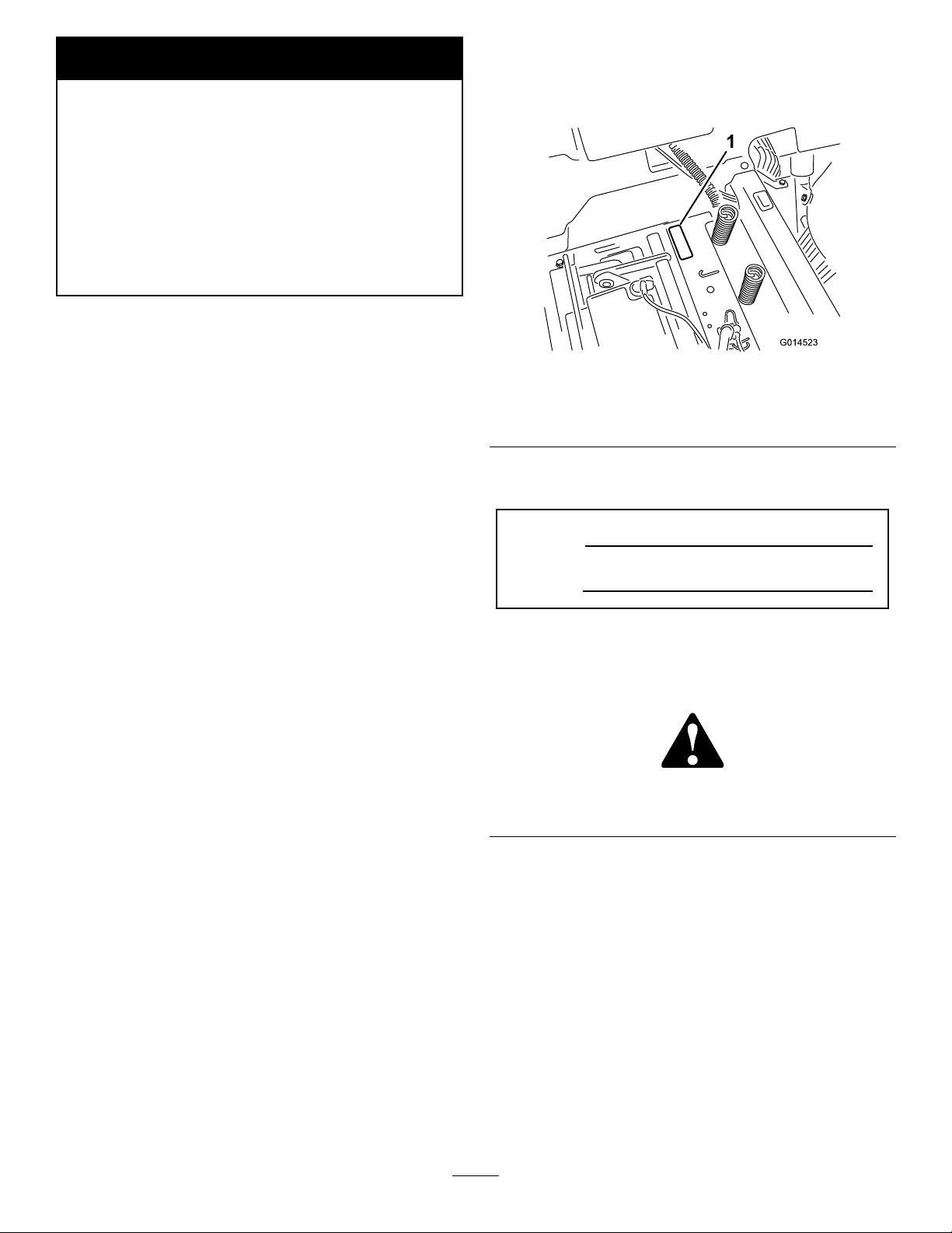
SlopeIndicator
G011841
Figure3
Thispagemaybecopiedforpersonaluse.
1.Themaximumslopeyoucansafelyoperatethemachineonis15degrees.Usetheslopecharttodeterminethedegreeofslope
ofhillsbeforeoperating.Donotoperatethismachineonaslopegreaterthan15degrees.Foldalongtheappropriateline
tomatchtherecommendedslope.
2.Alignthisedgewithaverticalsurface,atree,building,fencepole,etc.
3.Exampleofhowtocompareslopewithfoldededge
7
Page 8
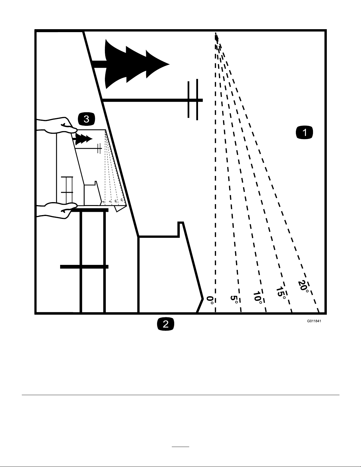
SafetyandInstructionalDecals
Safetydecalsandinstructionsareeasilyvisibletotheoperatorandarelocatednearanyareaofpotential
danger.Replaceanydecalthatisdamagedorlost.
93-7009
1.Warning—donotoperatethemowerwiththedeectorup
orremoved;keepthedeectorinplace.
2.Cutting/dismembermenthazardofhandorfoot,mower
blade—stayawayfrommovingparts.
112-9840
1.ReadtheOperator's
Manual.
2.Heightofcut
99-3943
1.Engine
1.Parkingposition4.Neutral
2.Fast5.Reverse
3.Slow
3.Removetheignitionkey
andreadtheinstructions
beforeservicingor
performingmaintenance.
119-8814
106-8717
1.Readtheinstructionsbeforeservicingorperforming
maintenance.
2.Checktirepressureevery25operatinghours.
3.Greaseevery25operatinghours.
4.Engine
119-8815
1.Parkingposition4.Neutral
2.Fast5.Reverse
3.Slow
8
Page 9
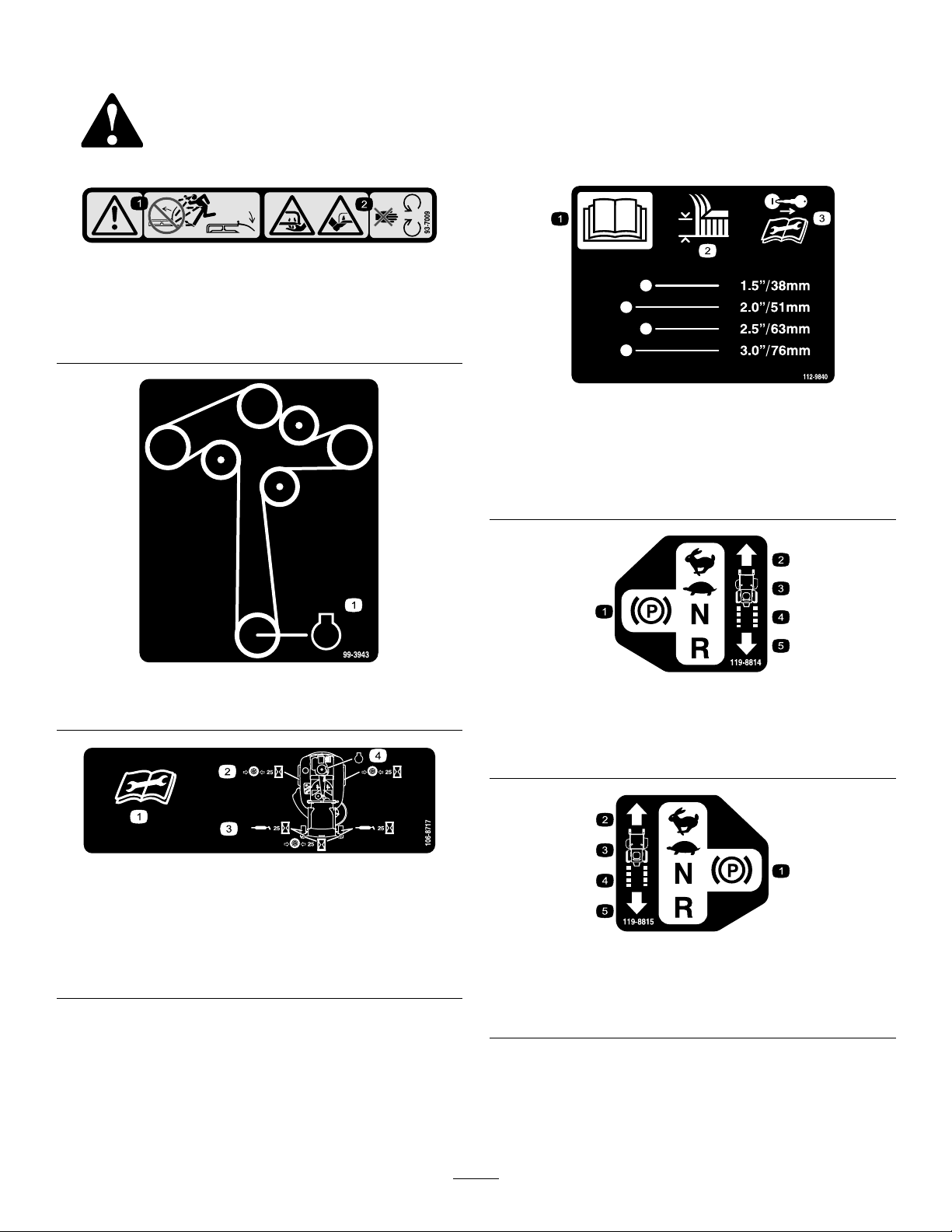
132-0872
1.Heightofcut
1.Thrownobject
hazard—keepbystanders
awayfromthemachine.
2.Thrownobjecthazard,
raisedbafe—donot
operatethemachinewith
anopendeck;usea
baggerorabafe.
3.Severinghazardofhand
orfoot—keepawayfrom
movingparts.
4.Entanglement
hazard—keepaway
frommovingparts;keep
allguardsandshieldsin
place.
119-8870
Manufacturer'sMark
1.Indicatesthebladeisidentiedasapartfromtheoriginal
machinemanufacturer.
1.Bypassleverpositionfor
pushingthemachine
1.Maximumdrawbarpull36
kg(80lb)
121-2989
2.Bypassleverpositionfor
operatingthemachine
131-4036
2.ReadtheOperator's
Manual.
BatterySymbols
Someorallofthesesymbolsareonyourbattery
1.Explosionhazard
2.Nore,opename,or
smoking.
3.Causticliquid/chemical
burnhazard
4.Weareyeprotection9.Flusheyesimmediately
5.ReadtheOperator's
Manual.
6.Keepbystandersasafe
7.Weareyeprotection;
8.Batteryacidcancause
10.Containslead;donot
distancefromthebattery.
explosivegasescan
causeblindnessandother
injuries
blindnessorsevereburns.
withwaterandgetmedical
helpfast.
discard.
9
Page 10
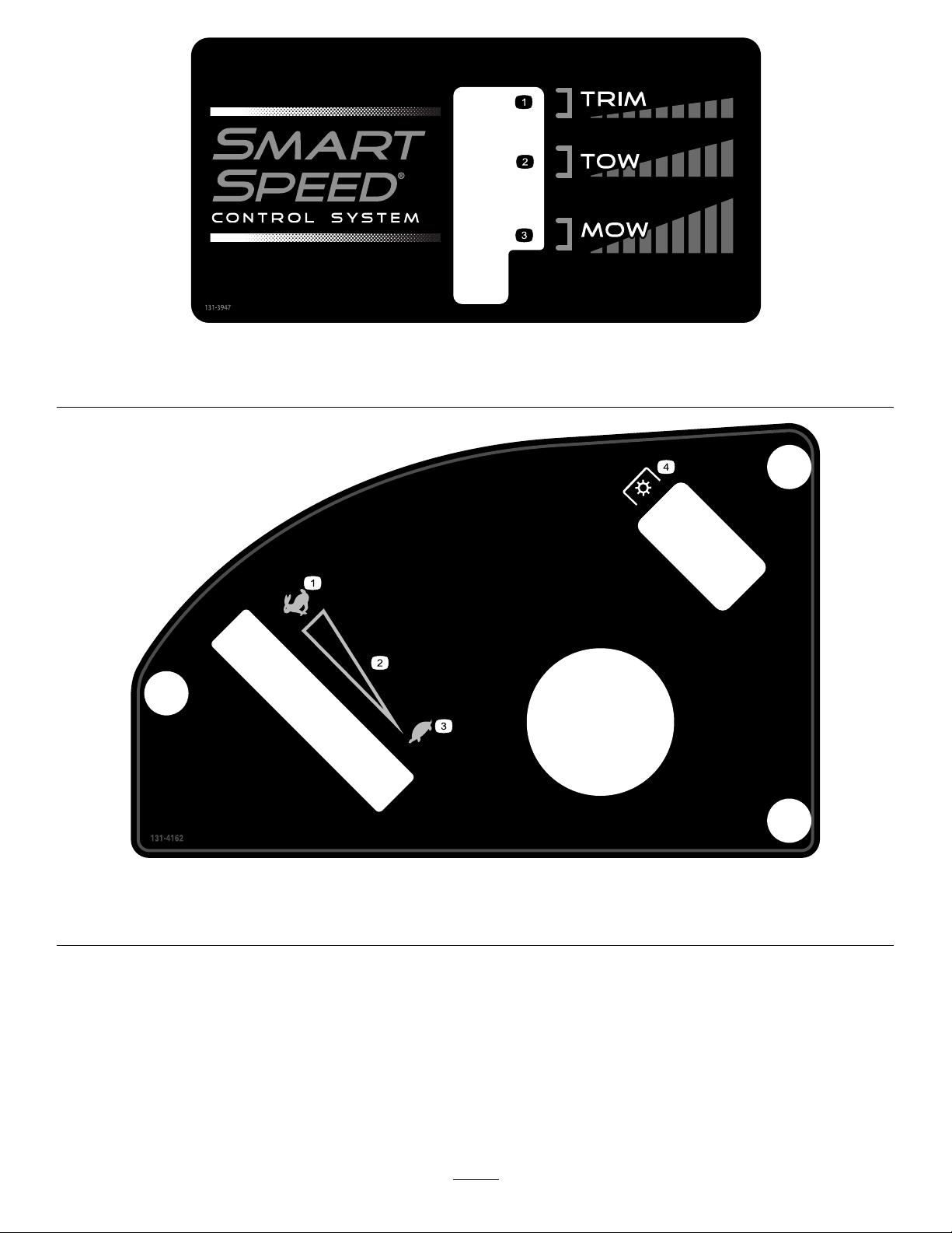
131-3947
1.Trim—slow
2.Tow—medium
3.Mow—fast
131-4162
1.Fast
2.Continuous-variablesetting4.Powertakeoff
3.Slow
10
Page 11
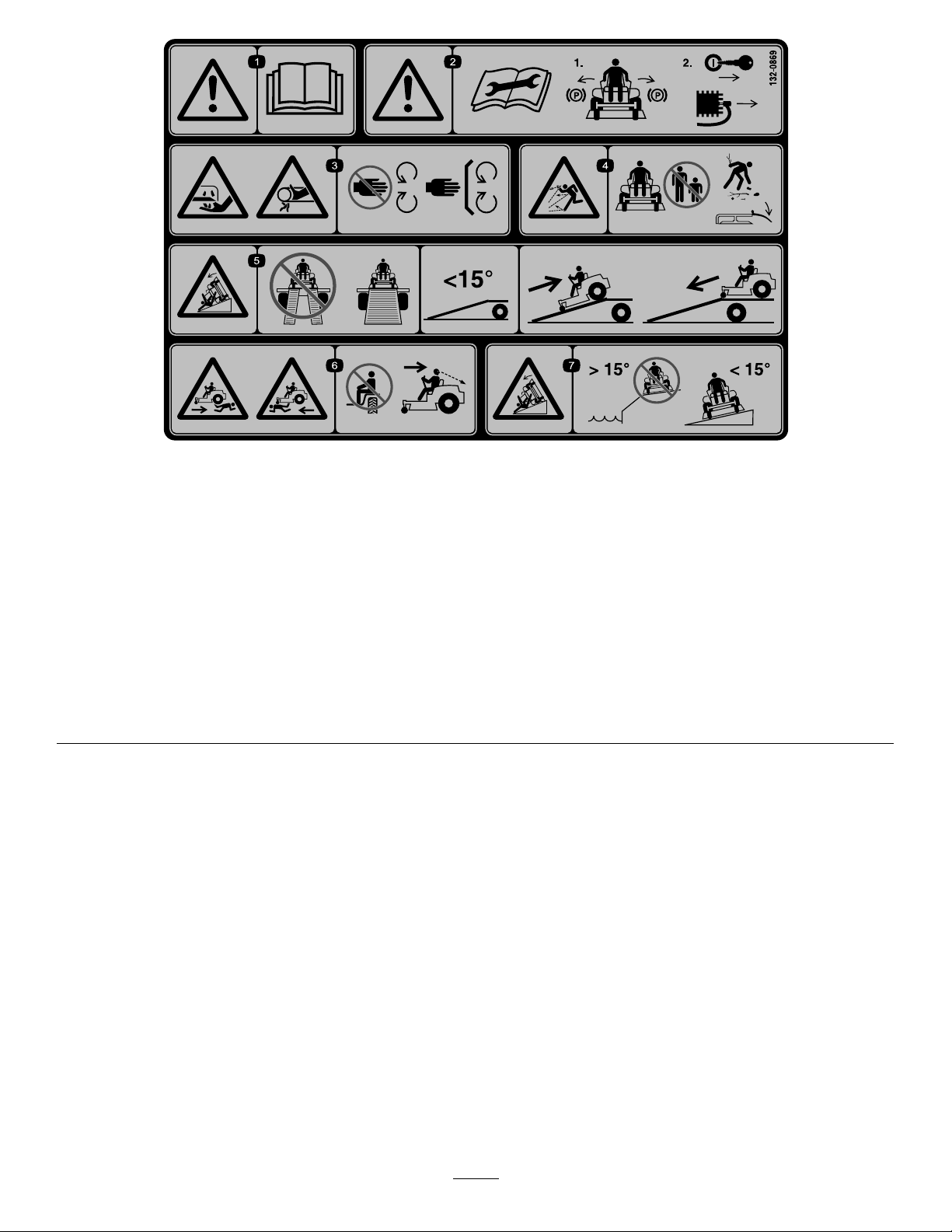
132-0869
1.Warning—readthe
Operator'sManual.
2.Warning—beforeservicing,
engagetheparkingbrake,
removethekeyandthe
sparkplugconnection.
3.Cuttinghazardofhand,
mowerblade;pinching
hazardofhand,belt—keep
handsandfeetawayfrom
movingparts;keepall
guardsandshieldsinplace.
4.Thrownobject
hazard—keepbystanders
awayfromthemachine;
removedebrisfromthe
areabeforemowing;keep
thedeectorshielddown.
5.Ramptipping
hazard—whenloading
ontoatrailer,donotuse
dualramps;onlyusea
singlerampwideenough
forthemachineandthat
hasaninclinelessthan
15degrees;backupthe
ramp(inreverse)anddrive
forwardofftheramp.
6.Bodilyharmhazard—no
riders;lookbehindyou
whenmowinginreverse.
7.Tippinghazardon
slopes—donotuseon
slopesnearopenwater;do
notuseonslopesgreater
than15degrees.
11
Page 12
ProductOverview
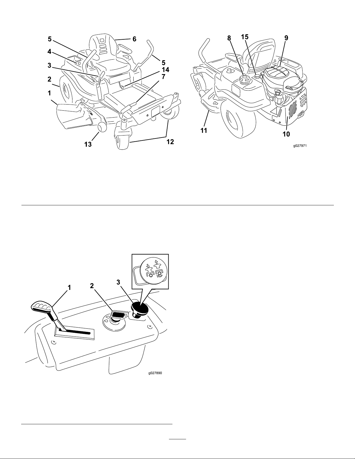
Figure4
1.Deector
2.Reardrivewheel
3.Height-of-cutlever7.Foot-assistlever(certain
4.Controlpanel
5.Motion-controllevers9.Engine13.Anti-scalproller
6.Seat
modelsonly)
8.Fuel-tankcap12.Frontcasterwheel
Controls
BecomefamiliarwithallthecontrolsinFigure4andFigure5
beforeyoustarttheengineandoperatethemachine.
10.Engineguard
11.Mowerdeck15.Hydraulicreservoir
14.SmartSpeed™lever
IgnitionSwitch
Theignitionswitchhas3positions:OFF,RUN,andSTART.
ThekeyturnstoSTARTandmovesbacktoRUNupon
release.TurningthekeytotheOFFpositionstopstheengine;
however,alwaysremovethekeywhenleavingthemachine
topreventsomeonefromaccidentallystartingtheengine
(Figure5).
Throttle
Thethrottlecontrolstheenginespeedandhasacontinuous
variablesettingfromSlowtoFast(Figure5).
Blade-ControlSwitch(PowerTakeoff)
Figure5
ControlPanel
1.Throttle3.Blade-controlswitch
(powertakeoff)
2.Ignitionswitch
Theblade-controlswitch,representedbyapower-takeoff
(PTO)symbol,engagesanddisengagespowertothemower
blades(Figure5).
12
Page 13
Motion-ControlLeversandPark
G014521
1
Position
Themotion-controlleversarespeed-sensitivecontrolsof
independentwheelmotors.Movingaleverforwardor
backwardturnsthewheelonthesamesideforwardorin
reverse;thewheelspeedisproportionaltotheamountyou
movethelever.Movethemotion-controlleversoutward
fromthecentertothePARKpositionwhenexitingthe
machine(Figure14).Alwayspositionthemotion-control
leversintothePARKpositionwhenyoustopthemachine
orleaveitunattended.
SmartSpeed™ControlSystemLever
TheSmartSpeed™Control-Systemlever,locatedbelowthe
operatingposition,givesyouachoicetodrivethemachineat
3speedranges—trim,tow ,andmow(Figure17).
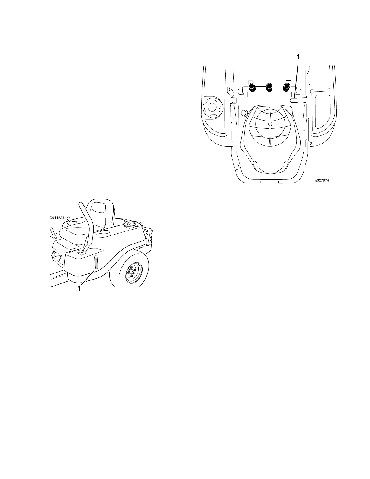
Fuel-PresenceWindow
Youcanusethefuelwindow ,locatedontheleftsideofthe
machine,toverifythepresenceofgasolineinthetank(Figure
6).
HourMeter
Thehourmeterrecordsthenumberofhourswhenyou
areintheseatandtheignitionswitchisintheONposition
(Figure7).
Figure7
1.Hourmeterlocationbehindtheseat
Figure6
1.Fuel-presencewindow
Height-of-CutLever
Usetheheight-of-cutlevertolowerandraisethedeckfrom
theseatedposition.Movingtheleverup(towardyou)raises
thedeckfromthegroundandmovingtheleverdown(away
fromyou)lowersthedecktowardtheground.Adjustthe
height-of-cutonlywhilethemachineisnotmoving(Figure
18).
13
Page 14

Operation
Note:Determinetheleftandrightsidesofthemachine
fromthenormaloperatingposition.
AddingFuel
•Forbestresults,useonlyclean,fresh(lessthan30days
old),unleadedgasolinewithanoctaneratingof87or
higher((R+M)/2ratingmethod).
•Ethanol:Gasolinewithupto10%ethanol(gasohol)
or15%MTBE(methyltertiarybutylether)byvolume
isacceptable.EthanolandMTBEarenotthesame.
Gasolinewith15%ethanol(E15)byvolumeisnot
approvedforuse.Neverusegasolinethatcontains
morethan10%ethanolbyvolume,suchasE15
(contains15%ethanol),E20(contains20%ethanol),or
E85(containsupto85%ethanol).Usingunapproved
gasolinemaycauseperformanceproblemsand/orengine
damagewhichmaynotbecoveredunderwarranty.
•Donotusegasolinecontainingmethanol.
•Donotstorefueleitherinthefueltankorfuelcontainers
overthewinterunlessafuelstabilizerisused.
•Donotaddoiltogasoline.
DANGER
Incertainconditionsduringfueling,static
electricitycanbereleased,causingasparkthatcan
ignitethegasolinevapors.Areorexplosionfrom
gasolinecanburnyouandothersandcandamage
property.
•Alwaysplacegasolinecontainersontheground
awayfromyourvehiclebeforelling.
•Donotllgasolinecontainersinsideavehicleor
onatruckortrailerbed,becauseinteriorcarpets
orplastictruckbedlinersmayinsulatethe
containerandslowthelossofanystaticcharge.
•Whenpractical,removegas-poweredequipment
fromthetruckortrailerandrefueltheequipment
withitswheelsontheground.
•Ifthisisnotpossible,thenrefuelsuch
equipmentonatruckortrailerfromaportable
containerratherthanfromagasoline-dispenser
nozzle.
•Ifyoumustuseagasoline-dispensernozzle,
keepthenozzleincontactwiththerimofthe
fueltankorcontaineropeningatalltimesuntil
fuelingiscomplete.
DANGER
Incertainconditions,gasolineisextremely
ammableandhighlyexplosive.Areorexplosion
fromgasolinecanburnyouandothersandcan
damageproperty.
•Fillthefueltankoutdoors,inanopenarea,
whentheengineiscold.Wipeupanygasoline
thatspills.
•Neverllthefueltankinsideanenclosedtrailer.
•Donotllthefueltankcompletelyfull.Add
gasolinetothefueltankuntilthelevelis6to13
mm(1/4to1/2inch)belowthebottomofthe
llerneck.Thisemptyspaceinthetankallows
gasolinetoexpand.
•Neversmokewhenhandlinggasoline,andstay
awayfromanopenameorwheregasoline
fumesmaybeignitedbyaspark.
•Storegasolineinanapprovedcontainerand
keepitoutofthereachofchildren.Neverbuy
morethana30-daysupplyofgasoline.
•Donotoperatewithoutentireexhaustsystemin
placeandinproperworkingcondition.
WARNING
Gasolineisharmfulorfatalifswallowed.Long-term
exposuretovaporscancauseseriousinjuryand
illness.
•Avoidprolongedbreathingofvapors.
•Keepfaceawayfromnozzleandgastankor
conditionerbottleopening.
•Avoidcontactwithskin;washoffspillswith
soapandwater.
UsingStabilizer/Conditioner
Useafuelstabilizer/conditionerinthemachinetoprovide
thefollowingbenets:
•Keepsgasolinefreshduringstorageof90daysorless.
Forlongerstorageitisrecommendedthatthefueltank
bedrained.
•Cleanstheenginewhileitruns.
•Eliminatesgum-likevarnishbuildupinthefuelsystem,
whichcauseshardstarting.
Important:Donotusefueladditivescontaining
methanolorethanol.
Addthecorrectamountofgasolinestabilizer/conditioner
tothegasoline.
Note:Afuelstabilizer/conditionerismosteffective
whenmixedwithfreshgasoline.T ominimizethechance
14
Page 15
ofvarnishdepositsinthefuelsystem,usefuelstabilizer
g027243
A
B
E
D
C
atalltimes.
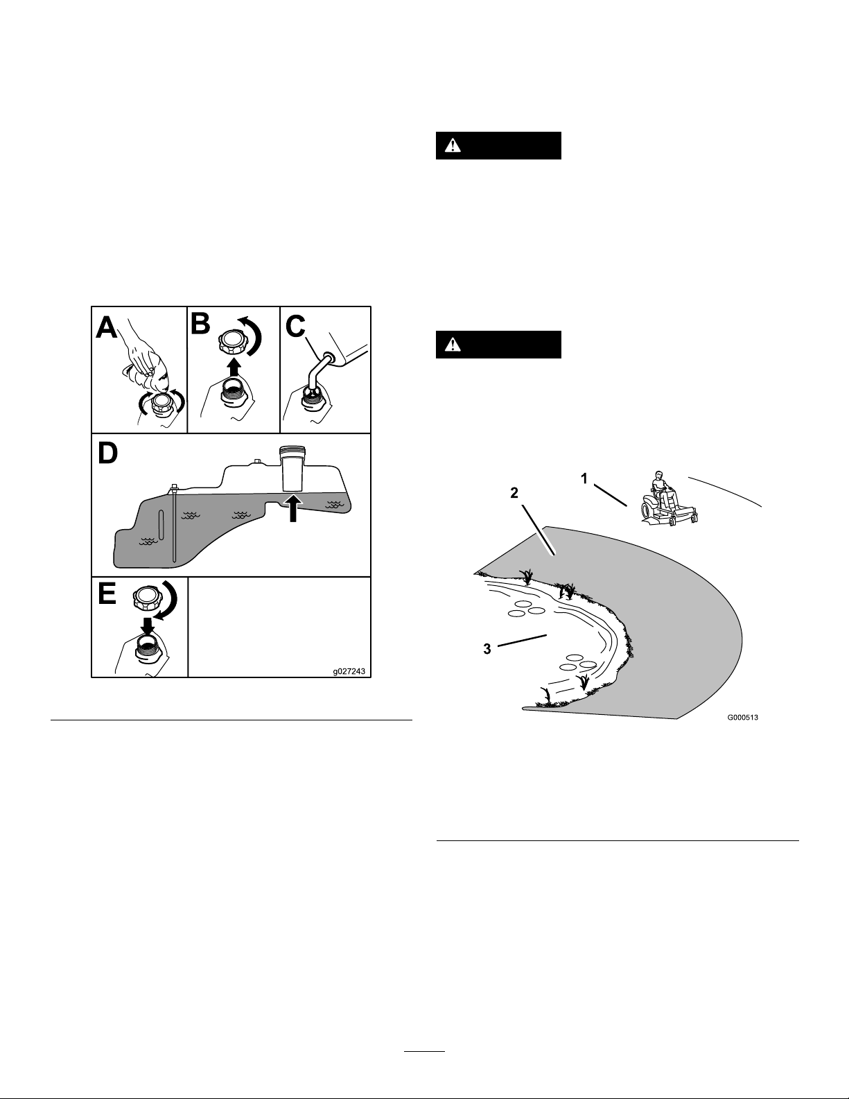
FillingtheFuelTank
Note:Ensurethattheengineisshutoffandthe
motion-controlleversareinthePARKEDposition.
ThinkSafetyFirst
Pleasereadallsafetyinstructionsandsymbolsinthesafety
section.Knowingthisinformationcouldhelpyouor
bystandersavoidinjury.
DANGER
Note:Youcanusethefuelwindowtoverifythepresenceof
gasolinebeforellingthetank(Figure8).
Important:Donotoverllthefueltank.Fillthefuel
tanktothebottomofthellerneck.Theemptyspace
inthetankallowsthefueltoexpand.Overllingmay
resultinfuelleakage,damagetotheengine,ordamage
totheemissionssystem.
Operatingthemachineonwetgrassorsteepslopes
cancauseslidingandlossofcontrol.
•Donotoperateonslopesgreaterthan15degrees.
•Reducespeedanduseextremecautionon
slopes.
•Donotoperatethemachinenearwater.
DANGER
Wheelsdroppingoveredgescancauserollovers,
whichmayresultinseriousinjury,death,or
drowning.
Donotoperatethemachineneardrop-offs.
Figure8
CheckingtheEngine-OilLevel
Beforeyoustarttheengineandusethemachine,check
theoillevelintheenginecrankcase;refertoCheckingthe
Engine-OilLevel(page27).
BreakinginaNewMachine
Newenginestaketimetodevelopfullpower.Mowerdecks
anddrivesystemshavehigherfrictionwhennew,placing
additionalloadontheengine.Allow40to50hoursof
break-intimefornewmachinestodevelopfullpowerand
bestperformance.
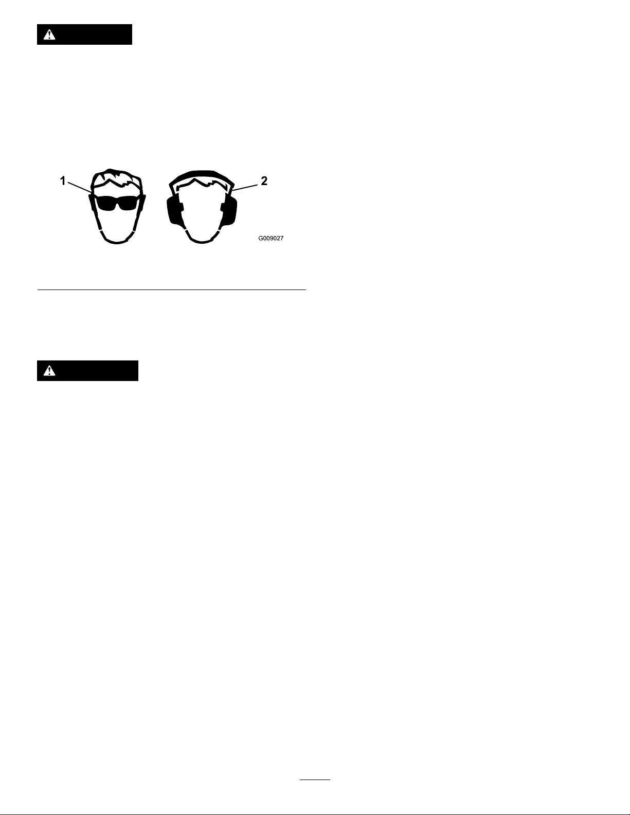
1.Safezone—usethe
machinehere
2.Useawalk-behindmower
and/orhandtrimmernear
drop-offsandwater.
15
Figure9
3.Water
Page 16
CAUTION
G009027
1
2
TestingtheSafety-Interlock
Thismachineproducessoundlevelsinexcessof
85dBAattheoperator’searandcancausehearing
lossthroughextendedperiodsofexposure.
Wearhearingprotectionwhenoperatingthis
machine.
Useprotectiveequipmentforyoureyes,ears,hands,feet,
andhead.
Figure10
1.Wearsafetyglasses.
2.Wearhearingprotection.
Understandingthe Safety-InterlockSystem
WARNING
Ifthesafety-interlockswitchesaredisconnectedor
damaged,themachinecouldoperateunexpectedly,
causingpersonalinjury.
System
Testthesafety-interlocksystembeforeyouusethemachine
eachtime.Ifthesafetysystemdoesnotoperateasdescribed
below,haveanAuthorizedServiceDealerrepairthesafety
systemimmediately.
1.Whilesittingontheseat,withthecontrolleversinthe
PARKposition,andmovetheblade-controlswitchto
theONposition.Trystartingtheengine;theengine
shouldnotcrank.
2.Whilesittingontheseat,movetheblade-controlswitch
totheOFFposition.Moveeithermotioncontrol
levertothecenter,unlockedposition.Trystartingthe
engine;theengineshouldnotcrank.Repeatwiththe
othermotion-controllever.
3.Whilesittingontheseat,movethebladecontrolswitch
totheOFFposition,andlockthemotion-controllevers
inthePARKposition.Starttheengine.Whilethe
engineisrunning,engagetheblade-controlswitch,and
riseslightlyfromtheseat;theengineshouldstop.
4.Whilesittingontheseat,movetheblade-controlswitch
totheOFFposition,andlockthemotion-controllevers
inthePARKposition.Starttheengine.Whilethe
engineisrunning,movethemotion-controlleversto
thecenter,unlockedposition,engagetheblade-control
switch,andriseslightlyfromtheseat;theengine
shouldstop.
•Donottamperwiththeinterlockswitches.
•Checktheoperationoftheinterlockswitches
dailyandreplaceanydamagedswitchesbefore
operatingthemachine.
Thesafety-interlocksystemisdesignedtopreventtheengine
fromstartingunless:
•Thebladesaredisengaged.
•Themotion-controlleversareinthePARKposition.
Thesafety-interlocksystemalsoisdesignedtostoptheengine
wheneverthecontrolleversareoutofthePARKpositionand
yourisefromtheseat.
16
Page 17
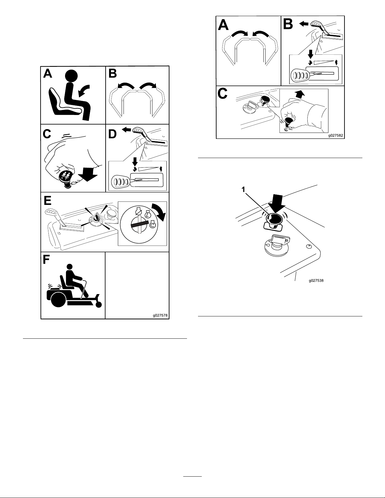
StartingtheEngine
g027578
B
C
D
E
A
F
g027582
B
C
A
1
g027538
Important:Donotengagethestarterformorethan
10secondsatatime.Iftheenginefailstostart,wait
60secondsbetweenattempts.Failuretofollowthese
instructionscandamagethestartermotor.
Figure12
DisengagingtheBlades
Figure11
OperatingtheBlades
Theblade-controlswitchengagesanddisengagespower
tothemowerblades.Thisswitchcontrolspowertoany
attachmentsthatdrawpowerfromtheengine,includingthe
mowerdeckandcuttingblades.
EngagingtheBlades
Important:Donotengagethebladeswhenthemachine
isparkedintallgrass.Beltorclutchdamagecanoccur.
Note:Alwaysengagethebladeswiththethrottleinthe
FASTposition.
Figure13
1.Blade-controlswitch—Off
StoppingtheEngine
1.Disengagethebladesbymovingtheblade-control
switchtotheOFFposition(Figure13).
2.MovethethrottlelevertotheFASTposition.
3.TurntheignitionkeytotheOFFpositionandremove
thekey.
17
Page 18
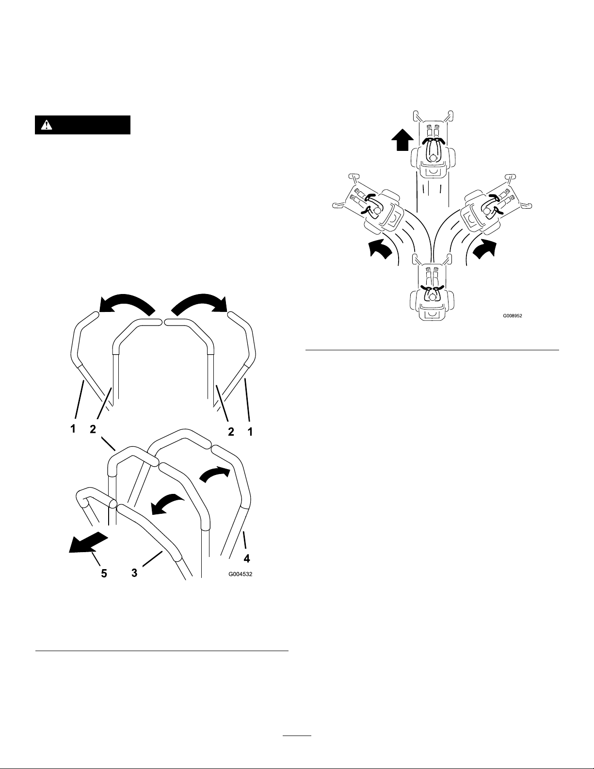
DrivingtheMachine
G008952
DrivingForward
Thedrivewheelsturnindependently,poweredbyhydraulic
motorsoneachaxle.Youcanturn1sideinreversewhileyou
turntheotherforward,causingthemachinetospinrather
thanturn.Thisgreatlyimprovesthemachinemaneuverability
butmayrequiresometimeforyoutoadapttohowitmoves.
WARNING
Themachinecanspinveryrapidly.Y oumaylose
controlofthemachineandcausepersonalinjuryor
damagetothemachine.
•Usecautionwhenmakingturns.
•Slowthemachinedownbeforemakingsharp
turns.
Thethrottlecontrolregulatestheenginespeedasmeasured
inrpm(revolutionsperminute).Setthethrottlecontrolin
theFASTpositionforperformance.Formostapplications,
operatethemachineinthefull-throttleposition.
Note:Alwaysusecautionwhenbackingupandturning.
1.Movetheleverstothecenter,unlockedposition.
2.Togoforward,slowlypushthemotion-controllevers
forward(Figure14).
Figure15
Figure14
1.Park(brake)position
2.Center,unlockposition5.Frontofthemachine
3.Forward
4.Backward
Togostraight,applyequalpressuretoboth
motion-controllevers(Figure15).
Toturn,releasepressureonthemotion-controllever
towardthedirectionyouwanttoturn(Figure15).
Thefartheryoumovethemotion-controlleversin
eitherdirection,thefasterthemachinemovesinthat
direction.
Tostop,pullthemotion-controlleverstoneutral.
18
Page 19

DrivingBackward
G008953
Tochangespeeds,dothefollowing:
Note:Alwaysusecautionwhenbackingupandturning.
1.Movetheleverstothecenter,unlockedposition.
2.Togobackward,lookbehindyouanddown,asyou
slowlypullthemotion-controlleversrearward(Figure
16).
Figure16
1.Movethemotion-controlleverstoneutralandoutward
tothePARKposition.
2.Disengagetheblade-controlswitch.
3.Adjustthelevertothedesiredposition.
Thefollowingareonlyrecommendationsforuse.
Adjustmentsvarybygrasstype,moisturecontent,andthe
heightofthegrass.
Suggested
uses:
ParkingX
Heavy,wet
grass
TrainingX
BaggingX
MulchingX
Normal
mowing
TransportX
TrimTowMow
X
X
Trim
Togostraight,applyequalpressuretoboth
motion-controllevers(Figure16).
Toturn,releasethepressureonthemotion-control
levertowardthedirectionyouwanttoturn.
Tostop,pushthemotion-controlleverstoneutral.
UsingtheSmartSpeed
TM
Control
System
TheSmartSpeed
operatingposition(Figure17),givestheoperatorachoice
todrivethemachineat3groundspeedranges—trim,tow ,
andmow .
TM
Control-Systemlever,locatedbelowthe
Thisisthelowestspeed.Thesuggestedusesforthisspeed
areasfollows:
•Parking
•Heavy,wetgrassmowingconditions
•Training
Tow
Thisisthemediumspeed.Thesuggestedusesforthisspeed
areasfollows:
•Bagging
•Mulching
Mow
Thisisthefastestspeed.Thesuggestedusesforthisspeed
areasfollows:
•Normalmowing
•Transportingthemachine
1.Smart-speedlever
Figure17
19
Page 20
StoppingtheMachine
G010233
1
2
3
4
AdjustingtheAnti-Scalp
Tostopthemachine,movethemotion-controlleversto
NEUTRALandoutwardtothePARKposition,disengagethe
blade-controlswitch,ensurethatthethrottleisintheFAST
position,andturntheignitionkeytoOFF.Removethekey
fromtheignitionswitch.
WARNING
Childrenorbystandersmaybeinjuredifthey
moveorattempttooperatethemowerwhileitis
unattended.
Alwaysremovetheignitionkeyandmovethe
motion-controlleversoutwardtothePARKposition
whenleavingthemachineunattended,evenifjust
forafewminutes.
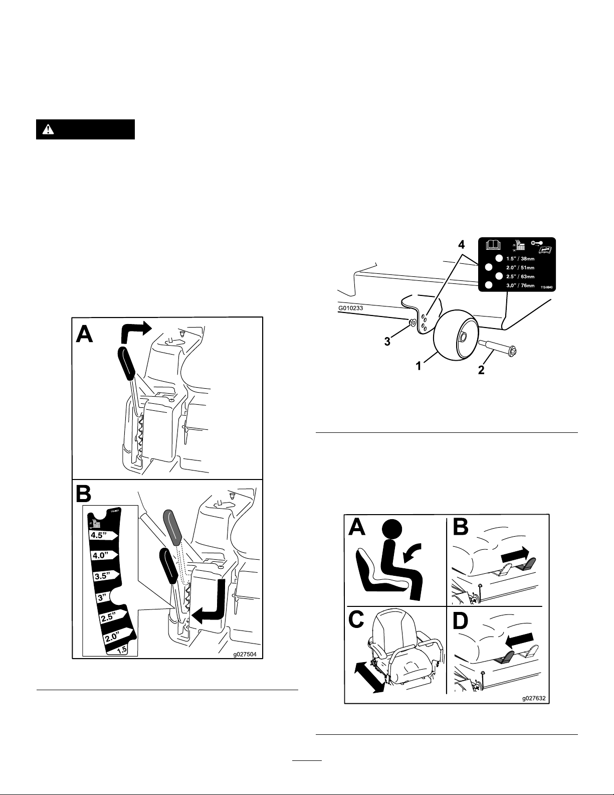
AdjustingtheHeight-of-Cut
Note:Thetransportpositionisthehighestheight-of-cut
positionat115mm(4-1/2inches)asshowninFigure18.
Rollers
Wheneveryouchangetheheightofcut,adjusttheheight
oftheanti-scalprollers.
Note:Adjusttheanti-scalprollerssothattherollersdonot
touchthegroundinnormal,atmowingareas.
1.Disengagetheblade-controlswitch(PTO),movethe
motion-controlleverstotheNEUTRAL-LOCKposition,
andsettheparkingbrake.
2.Shutofftheengine,removethekey ,andwaitforall
movingpartstostopbeforeleavingtheoperating
position.
3.Adjusttheanti-scalprollersasshowninFigure19to
matchtheclosestheight-of-cutposition.
Figure19
1.Anti-scalproller3.FlangeNut
2.Bolt4.Holespacing
PositioningtheSeat
Theseatcanmoveforwardandbackward.Positiontheseat
whereyouhavethebestcontrolofthemachineandaremost
comfortable.
Figure18
Figure20
20
Page 21
AdjustingtheMotion-Control
g027252
B
A
g017303
1 2
3
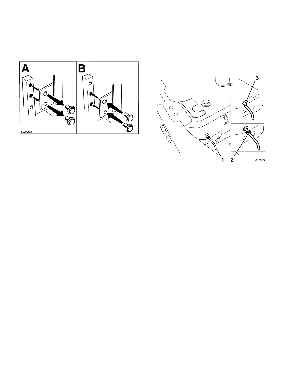
4.Movethebypassleversforwardthroughthekeyhole
anddowntolocktheminplace(Figure22).
Levers
Note:Dothisforeachlever.
AdjustingtheHeight
Youcanadjustthemotion-controllevershigherorlowerfor
maximumcomfort(Figure21).
Figure21
AdjustingtheTilt
Youcanadjustthemotion-controlleversforwardorrearward
foryourcomfort.
1.Loosentheupperboltholdingthecontrollevertothe
control-armshaft.
5.Movethemotion-controlleversinwardtothe
NEUTRALpositionandturntheignitionkeytothe
RUNposition.
Note:Donotstartthemachine.
Note:Youcannowpushthemachinebyhand.
Figure22
1.Bypass-leverlocations
2.Leverpositionfor
operatingthemachine
3.Leverpositionforpushing
themachine
2.Loosenthelowerboltjustenoughtopivotthecontrol
leverforwardorrearward(Figure21).
3.Tightenbothboltstosecurethecontrolleverinthe
newposition.
4.Repeattheadjustmentfortheothercontrollever.
PushingtheMachinebyHand
Important:Alwayspushthemachinebyhand.Donot
towthemachine,becausedamagemayoccur.
Thismachinehasanelectric-brakemechanism,andtopush
themachine,turntheignitionkeytotheRUNposition.The
batteryneedstobechargedandfunctioningtodisengage
theelectricbrake.
PushingtheMachine
1.Parkthemachineonalevelsurfaceanddisengagethe
blade-controlswitch.
2.Movethemotion-controlleversoutwardtothePARK
position,shutofftheengine,andwaitforallmoving
partstostopbeforeleavingtheoperatingposition.
6.Whennished,turnthekeytotheSTOPpositionto
avoiddrainingthebatterycharge.
Note:Ifthemachinefailstomove,theelectricbrakemay
stillbeengaged.Ifnecessary,releasetheelectricbrake
manually;refertoReleasingtheElectricBrake(page34).
OperatingtheMachine
Movethebypassleversrearwardthroughthekeyholeand
downtolocktheminplaceasshowninFigure22.
Note:Dothisforeachlever.
3.Locatethebypassleversontheframeonbothsidesof
theengine.
21
Page 22

UsingtheGrassDeector
Themowerhasahingedgrassdeectorthatdisperses
clippingstothesideanddowntowardtheturf.
DANGER
Withoutthegrassdeector,dischargecover,or
completegrass-catcherassemblymountedin
place,youandothersareexposedtobladecontact
andthrowndebris.Contactwithrotatingmower
blade(s)andthrowndebriswillcauseinjuryor
death.
Figure23
•Neverremovethegrassdeectorfromthemower
becausethegrassdeectorroutesmaterialdown
towardtheturf.Ifthegrassdeectorisever
damaged,replaceitimmediately .
•Neverputyourhandsorfeetunderthemower.
•Nevertrytocleardischargeareaormower
bladesunlessyoumovetheblade-controlswitch
toOFFandrotatetheignitionkeytoOFF.Also
removethekeyandpullthewireoffthespark
plug(s).
TransportingtheMachine
Useaheavy-dutytrailerortrucktotransportthemachine.
Ensurethatthetrailerortruckhasallnecessarybrakes,
lighting,andmarkingasrequiredbylaw .Pleasecarefullyread
allthesafetyinstructions.Knowingthisinformationcould
helpyou,yourfamily,pets,orbystandersavoidinjury.
WARNING
Drivingonthestreetorroadwaywithout
turnsignals,lights,reectivemarkings,ora
slow-moving-vehicleemblemisdangerousandcan
leadtoaccidents,causingpersonalinjury.
Donotdrivethemachineonapublicstreetor
roadway.
1.Ifyouareusingatrailer,connectittothetowing
vehicleandconnectthesafetychains.
LoadingtheMachine
Useextremecautionwhenloadingorunloadingthemachine
ontoatraileroratruck.Useafull-widthrampthatiswider
thanthemachineforthisprocedure.Backthemachineupthe
rampsanddriveitforwarddowntheramps(Figure24).
Figure24
1.Backthemachineup
ramps.
Important:Donotusenarrowindividualrampsfor
eachsideofthemachine.
Ensuretherampislongenoughsothattheanglewiththe
grounddoesnotexceed15degrees(Figure25).Onat
ground,thisrequiresaramptobeatleast4timesaslongas
theheightofthetrailerortruckbedtotheground.Asteeper
anglemaycausemowercomponentstogetcaughtasthe
machinemovesfromtheramptothetrailerortruck.Steeper
anglesmayalsocausethemachinetotiporlosecontrol.If
youareloadingthemachineonornearaslope,positionthe
trailerortrucksothatitisonthedownsideoftheslopeand
therampextendsuptheslope.Thiswillminimizetheramp
angle.
2.Drivethemachineforward
downramps.
2.Ifapplicable,connectthetrailerbrakes.
3.Loadthemachineontothetrailerortruck.
4.Shutofftheengine,removethekey,setthebrake,and
closethefuelvalve.
5.Tiedownthemachinenearthefrontcasterwheelsand
therearbumper(Figure23).
22
Page 23

WARNING
g027996
5
1
2
6
Loadingamachineontoatrailerortruckincreases
thepossibilityofatip-overandcouldcauseserious
injuryordeath.
•Useextremecautionwhenoperatingamachine
onaramp.
•Useonlyafull-widthramp;donotuseindividual
rampsforeachsideofthemachine.
•Donotexceeda15-degreeanglebetweenthe
rampandthegroundorbetweentherampand
thetrailerortruck.
•Ensurethelengthoframpisatleast4timesas
longastheheightofthetrailerortruckbedto
theground.Thiswillensurethatrampangle
doesnotexceed15degreesonatground.
•Backthemachineuprampsanddriveitforward
downramps.
•Avoidsuddenaccelerationordecelerationwhile
drivingthemachineonarampasthiscould
causealossofcontroloratip-over.
Figure25
1.Full-widthrampinstowed
position
2.Sideviewoffull-width
rampinloadingposition
3.Notgreaterthan
15degrees
4.Rampisatleast4times
aslongastheheightof
thetrailerortruckbedto
theground
5.H=heightofthetraileror
truckbedtotheground
6.Trailer
23
Page 24

OperatingTips
FastThrottleSetting
Forbestmowingandmaximumaircirculation,operatethe
engineattheFASTposition.Airisrequiredtothoroughlycut
grassclippings,sodonotsettheheight-of-cutsolowasto
surroundthemowerinuncutgrass.Alwaystrytohave1side
ofthemowerfreefromuncutgrass,whichallowsairtobe
drawnintothemower.
UsingtheSmartSpeed™Control
System
LongGrass
Ifthegrassiseverallowedtogrowslightlylongerthan
normal,orifitcontainsahighdegreeofmoisture,raisethe
cuttingheighthigherthanusualandcutthegrassatthis
setting.Thencutthegrassagainusingthelower,normal
setting.
WhenStopping
Ifyoumuststopthemachine'sforwardmotionwhilemowing,
aclumpofgrassclippingsmaydropontoyourlawn.Toavoid
this,moveontoapreviouslycutareawiththebladesengaged.
TheSmartSpeed™ControlSystemlever,locatedbelowthe
operatingposition,givesyouachoicetodrivethemachineat
3speedranges—high,tow ,andlow.Youcanbenetfromthe
lowerspeedsettingwhenmaneuveringthemachineintight
spacesoroperatingarounddelicatelandscapes.Youcanalso
usethelowsettingtooperatethemachineatahighthrottle
settingandbladespeedwhilestillbeingabletoreduceground
speedtoincreasethequalityofcut.
CuttingaLawnfortheFirstTime
Cutthegrassslightlylongerthannormaltoensurethat
thecuttingheightofthemowerdoesnotscalpanyuneven
ground.However,thecuttingheightusedinthepastis
generallythebesttouse.Whencuttinggrasslongerthan15
cm(6inches)tall,youmaywanttocutthelawntwiceto
ensureanacceptablequalityofcut.
CutaThirdoftheGrassBlade
Itisbesttocutonlyabout1/3ofthegrassblade.Cutting
morethanthatisnotrecommendedunlessgrassissparse,or
itislatefallwhengrassgrowsmoreslowly.
KeeptheUndersideoftheMowerClean
Cleanclippingsanddirtfromtheundersideofthemower
aftereachuse.Ifgrassanddirtbuildupinsidethemower,the
cuttingqualityeventuallybecomesunsatisfactory.
BladeMaintenance
Maintainasharpbladethroughoutthecuttingseason,because
asharpbladecutscleanlywithouttearingorshreddingthe
grassblades.Tearingandshreddingturnsgrassbrownat
theedges,whichslowsgrowthandincreasesthechanceof
disease.Checkthecutterbladesdailyforsharpnessandfor
anywearordamage.Filedownanynicksandsharpenthe
bladesasnecessary.Ifabladeisdamagedorworn,replaceit
immediatelywithagenuineT ororeplacementblade.
MowingDirection
Alternatethemowingdirectiontokeepthegrassstanding
straight.Thisalsohelpsdisperseclippings,whichenhances
decompositionandfertilization.
MowatCorrectIntervals
Normally,mowevery4days.However,grassgrowsat
differentratesatdifferenttimes.Tomaintainthesamecutting
height,whichisagoodpractice,mowmoreofteninearly
spring.Asthegrassgrowthrateslowsinmidsummer,mow
lessfrequently .Ifyoucannotmowforanextendedperiod,
rstmowatahighcuttingheight;thenmowagain2days
lateratalowerheightsetting.
AvoidCuttingTooLow
Ifthecuttingwidthofthemoweriswiderthanthemower
youpreviouslyused,raisethecuttingheighttoensurethat
uneventurfisnotcuttooshort.
24
Page 25

Maintenance
Note:Determinetheleftandrightsidesofthemachinefromthenormaloperatingposition.
RecommendedMaintenanceSchedule(s)
MaintenanceService
Interval
Aftertherst50hours
Beforeeachuseordaily
Aftereachuse
Every25hours
Every50hours
Every100hours
Every200hours
Every400hours
MaintenanceProcedure
•Changetheuidandltersforthehydraulicsystemandbleedthesystem.
•Checkthesafety-interlocksystem.
•Checktheaircleanerfordirty,looseordamagedparts.
•Checktheengine-oillevel.
•Checkthecuttingblades.
•Inspectthegrassdeectorfordamage.
•Cleanthemower-deckhousing.
•Greasealllubricationpoints.
•Checktirepressure.
•Checkthehydraulicuidlevelintheexpansiontank.
•Checkthebeltsforwearorcracks.
•Servicetheair-cleanerpaperelement(moreoftenunderextremelydusty,dirty
conditions).
•Replacetheair-cleanerpaperelement(moreoftenunderextremelydusty,dirty
conditions).
•Changetheengineoilandtheengine-oillter.
•Cleantheblowerhousing(moreoftenunderextremelydusty,dirtyconditions).
•Replacethein-linefuellter.
•Checkthesparkplug(s)conditionandgap.
•Changetheuidandltersforthehydraulicsystemandbleedthesystem.
Every500hours
Beforestorage
•Replacethesparkplug(s).
•Chargethebatteryanddisconnectthebatterycables.
•Performallmaintenanceprocedureslistedabovebeforestorage.
•Paintanychippedsurfaces.
Important:Refertoyourengineowner’smanualforadditionalmaintenanceprocedures.
CAUTION
Ifyouleavethekeyintheignitionswitch,someonecouldaccidentlystarttheengineandseriouslyinjure
youorotherbystanders.
Removethekeyfromtheignitionanddisconnectthewirefromthesparkplugbeforeyoudoany
maintenance.Setthewireasidesothatitdoesnotaccidentallycontactthesparkplug.
25
Page 26

Premaintenance
Lubrication
Procedures
GreasingtheBearings
RaisingtheSeat
Makesurethatthemotion-controlleversarelockedinthe
PARKposition.Lifttheseatforward.
Youcanaccessthefollowingcomponentsbyraisingtheseat:
•Serialplate
•Servicedecal
•Seat-adjustmentbolts
•Fuellter
•Batteryandbatterycables
ServiceInterval:Every25hours—Greasealllubrication
points.
GreaseType:No.2lithiumgrease
1.Parkthemachineonalevelsurfaceanddisengagethe
blade-controlswitch.
2.Movethemotion-controlleversoutwardtothePARK
position,shutofftheengine,removethekey,and
waitforallmovingpartstostopbeforeleavingthe
operatingposition.
3.Cleanthegreasettings(Figure26andFigure27)with
arag.
Note:Makesuretoscrapeanypaintoffthefrontof
thetting(s).
Figure26
1.Frontcastertire
Figure27
Locatedontheseat-panunderside
1.Readtheinstructions
beforeservicingor
performingmaintenance.
2.Checkthetirepressure
every25operatinghours.
4.Connectagreaseguntoeachtting(Figure26and
Figure27).
5.Pumpgreaseintothettingsuntilgreasebeginsto
oozeoutofthebearings.
3.Greaseevery25operating
hours.
4.Engine
26
Page 27
EngineMaintenance
g017552
0
0
50
SAE 30
ServicingtheAirCleaner
ServiceInterval:Beforeeachuseordaily—Checktheair
cleanerfordirty,looseordamagedparts.
Every50hours—Servicetheair-cleanerpaperelement
(moreoftenunderextremelydusty,dirtyconditions).
Every100hours—Replacetheair-cleanerpaper
element(moreoftenunderextremelydusty,dirty
conditions).
Thisengineisequippedwithareplaceable,high-densitypaper
air-cleanerelement.Checktheaircleanerdailyorbefore
startingtheengine.Checkforabuildupofdirtanddebris
aroundtheair-cleanersystem.Keepthisareaclean.Also,
checkforlooseordamagedcomponents.Replaceallbentor
damagedair-cleanercomponents.
Note:Operatingtheenginewithlooseordamaged
air-cleanercomponentscouldallowunlteredairintothe
engine,causingprematurewearandfailure.
1.Rotatethelatchesoutward.
2.Removethecovertoaccesstheair-cleanerelement
(Figure28).
3.Removetheelement,andgentlytaptheelementto
dislodgedirt.
Note:Donotwashthepaperelementoruse
pressurizedair,asthiswilldamagetheelement.
Note:Replaceadirty,bent,ordamagedelement.
Handlethenewelementcarefully;donotuseifthe
sealingsurfacesarebentordamaged.
4.Cleantheair-cleanerbaseasrequiredandcheckthe
condition.
5.Installthepaperelementontotheair-cleanerbase.
6.Installthecoverandsecureitwiththelatches(Figure
28).
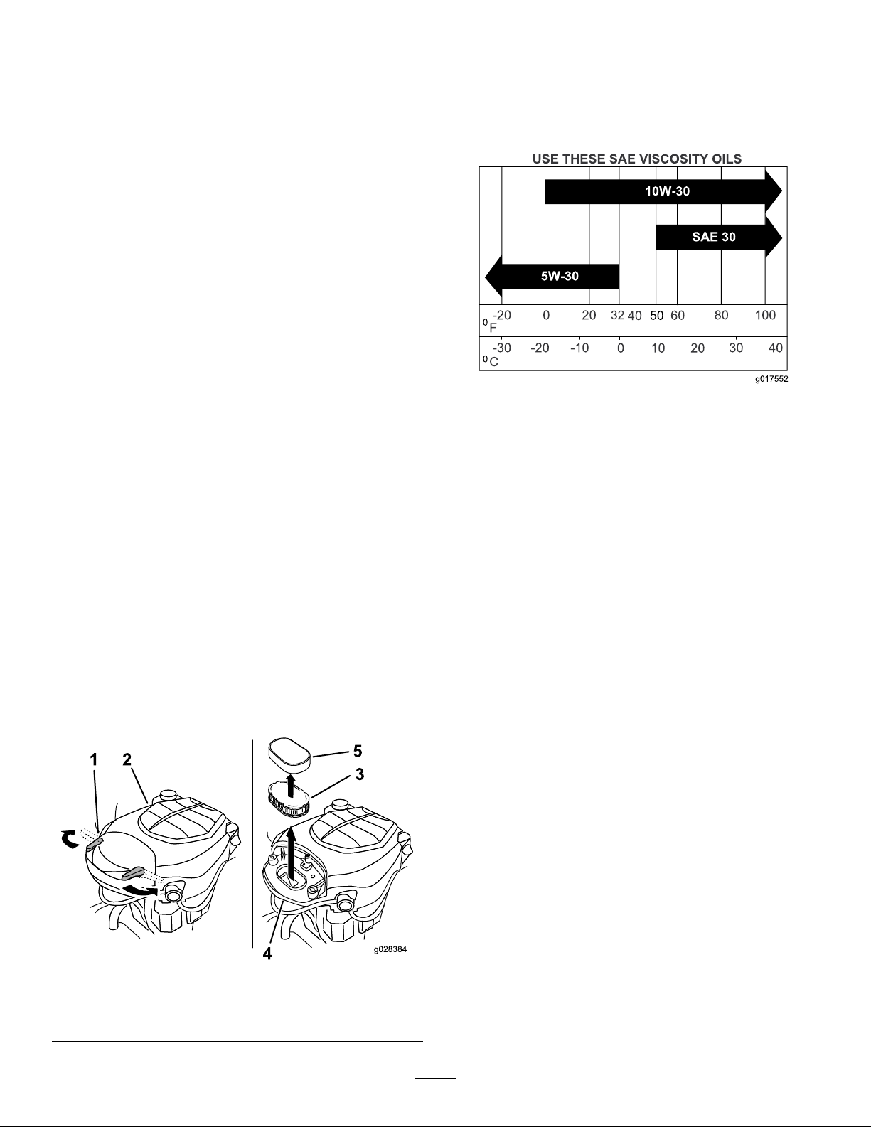
ServicingtheEngineOil
OilType:Detergentoil(APIserviceSJorhigher)
CrankcaseCapacity:1.9L(64oz)whenthelterischanged
Viscosity:Seethetablebelow.
Figure29
CheckingtheEngine-OilLevel
ServiceInterval:Beforeeachuseordaily—Checkthe
engine-oillevel.
1.Parkthemachineonalevelsurface,disengagethe
blade-controlswitch,shutofftheengine,andremove
thekey.
2.Makesuretheengineisstopped,level,andcoolsothe
oilhastimetodrainintothesump.
3.Checktheengine-oillevel(Figure30).
Figure28
1.Air-cleanerlatch3.Paperelement
2.Engine4.Air-cleanerbase
27
Page 28

B
A
C
D
E
g027515
F
G
H
ChangingtheEngineOilandthe
Engine-OilFilter
ServiceInterval:Every100hours—Changetheengineoil
andtheengine-oillter.
Note:Thedrainplugisattachedtothedrainhose.
Note:Disposetheusedoilatarecyclingcenter.
FillwithoilasspeciedinthetabletitledUseTheseSAE
ViscosityOils(Figure29).
1.Parkthemachinesothatthedrainsideisslightlylower
thantheoppositesidetoensurethattheoildrains
completely.
2.Disengagetheblade-controlswitchandmovethe
motion-controlleversoutwardtothePARKposition.
3.Shutofftheengine,removethekey ,andwaitforall
movingpartstostopbeforeleavingtheoperating
position.
Figure30
Figure31
28
Page 29

4.Torquetheplugto14N∙m(125in-lb).
B
A
C D
E
F
3/4
g027477
B
A
C
D
E
g027517
5.Slowlypourapproximately80%ofthespeciedoil
intothellertube(Figure33).
Figure32
Figure33
ServicingtheSparkPlug
ServiceInterval:Every200hours—Checkthesparkplug(s)
conditionandgap.
Every500hours—Replacethesparkplug(s).
ThesparkplugisRFIcompliant.Equivalentalternatebrand
plugscanalsobeused.
Type:ChampionXC12YC
AirGap:0.76mm(0.03inch)
RemovingtheSparkPlug
1.Disengagetheblade-controlswitch,movethe
motion-controlleversoutwardtothePARKposition,
shutofftheengine,andremovethekey .
2.Beforeremovingthesparkplug(s),cleanthearea
aroundthebaseoftheplugtokeepdirtanddebrisout
oftheengine.
3.Removethesparkplug(Figure34).
29
Page 30

B
A
g027478
Figure34
B
A
g027479
CleaningtheBlowerHousing
Toensurepropercooling,makesurethatthegrassscreen,
coolingns,andotherexternalsurfacesoftheengineare
keptcleanatalltimes.
Annually,orevery100hoursofoperation(moreoftenunder
extremelydusty,dirtyconditions),removetheblowerhousing
andanyothercoolingshrouds.Cleanthecoolingnsand
externalsurfacesasnecessary.Makesurethatthecooling
shroudsareinstalled.Torquetheblowerhousingscrewsto
7.5N·m(5.5ft-lb).
CheckingtheSparkPlug
Important:Donotcleanthesparkplug(s).Always
replacethesparkplug(s)whenithas:ablackcoating,
wornelectrodes,anoilylm,orcracks.
Note:Ifyouseelightbrownorgrayontheinsulator,the
engineisoperatingproperly.Ablackcoatingontheinsulator
usuallymeanstheaircleanerisdirty.
Setthegapto0.76mm(0.030inch).
Figure35
InstallingtheSparkPlug
Important:Operatingtheenginewithablocked
grassscreen,dirtyorpluggedcoolingns,and/or
coolingshroudsremoved,causesenginedamagedue
tooverheating.
Tightenthesparkplugto25to29N∙m(18to22ft-lb).
Figure36
30
Page 31
FuelSystem
B
A
C
D
g027753
Maintenance
DANGER
Incertainconditions,gasolineisextremely
ammableandhighlyexplosive.Areorexplosion
fromgasolinecanburnyouandothersandcan
damageproperty.
•Performanyfuel-relatedmaintenancewhenthe
engineiscold.Dothisoutdoorsinanopenarea.
Wipeupanygasolinethatspills.
•Neversmokewhendraininggasolineandstay
awayfromanopenameorwhereasparkmay
ignitethegasolinefumes.
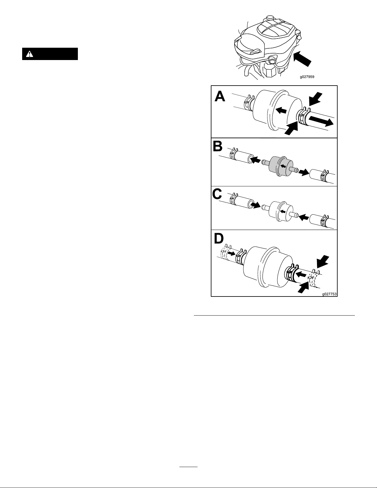
ReplacingtheIn-LineFuel Filter
ServiceInterval:Every100hours—Replacethein-linefuel
lter.
Neverinstalladirtylterifitisremovedfromthefuelline.
1.Parkthemachineonalevelsurfaceanddisengagethe
blade-controlswitch.
2.Movethemotion-controlleversoutwardtothePARK
position,shutofftheengine,removethekey,and
waitforallmovingpartstostopbeforeleavingthe
operatingposition.
3.Replacethein-linelter(Figure37).
Figure37
31
Page 32

ElectricalSystem
g017701
2
3
4
5
6
7
1
Maintenance
WARNING
Incorrectbattery-cableroutingcoulddamage
themachineandcablescausingsparks.
Sparkscancausethebatterygassesto
WARNING
explode,resultinginpersonalinjury.
CALIFORNIA
Proposition65Warning
Batteryposts,terminals,andrelated
accessoriescontainleadandleadcompounds,
chemicalsknowntotheStateofCalifornia
tocausecancerandreproductiveharm.
Washhandsafterhandling.
ChargingtheBattery
RemovingtheBattery
WARNING
Batteryterminalsormetaltoolscouldshortagainst
metalmachinecomponentscausingsparks.Sparks
cancausethebatterygassestoexplode,resulting
inpersonalinjury.
•Whenremovingorinstallingthebattery,donot
allowthebatteryterminalstotouchanymetal
partsofthemachine.
•Alwaysdisconnectthenegative(black)
batterycablebeforedisconnectingthe
positive(red)cable.
•Alwaysconnectthepositive(red)battery
cablebeforeconnectingthenegative
(black)cable.
5.Slidetherubbercoverupthepositive(red)cable.
6.Disconnectthepositive(red)cablefromthebattery
post(Figure38).
Note:Retainallfasteners.
7.Removethebatteryhold-downandliftthebattery
fromthebatterytray(Figure38).
•Donotallowmetaltoolstoshortbetween
thebatteryterminalsandmetalpartsofthe
machine.
1.Parkthemachineonalevelsurfaceanddisengagethe
blade-controlswitch.
2.Movethemotion-controlleversoutwardtothePARK
position,shutofftheengine,removethekey,and
waitforallmovingpartstostopbeforeleavingthe
operatingposition.
3.Raisetheseattoaccessthebattery.
4.Disconnectthenegative(black)groundcablefromthe
batterypost(Figure38).
Note:Retainallfasteners.
Figure38
1.Battery
2.Positive(+)batterypost
3.Bolt,washer,andnut7.Batteryhold-down
4.Terminalboot
5.Negative(–)batterypost
6.Wingnut,washer,andbolt
32
Page 33
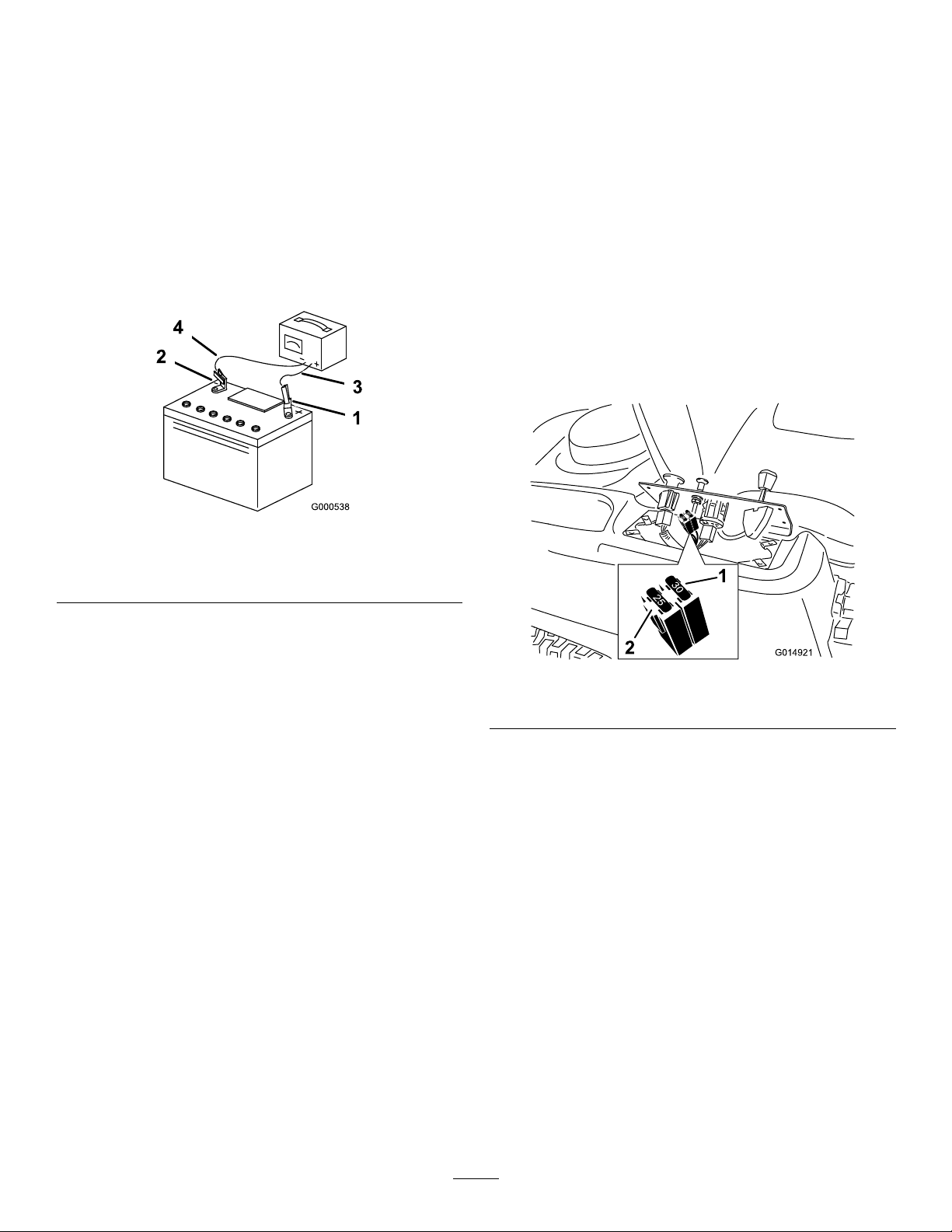
ChargingtheBattery
30
25
30
25
G014921
2
1
ServicingtheFuses
ServiceInterval:Beforestorage—Chargethebatteryand
disconnectthebatterycables.
1.Removethebatteryfromthechassis;refertoRemoving
theBattery(page32).
2.Chargethebatteryforaminimumof1hourat6to
10A.
Note:Donotoverchargethebattery.
3.Whenthebatteryisfullycharged,unplugthecharger
fromtheelectricaloutlet,thendisconnectthecharger
leadsfromthebatteryposts(Figure39).
Figure39
Theelectricalsystemisprotectedbyfuses.Itrequiresno
maintenance;however,ifafuseblows,checkthecomponent
orcircuitforamalfunctionorshort.
Fusetype:
•Main—F1-30A,blade-type
•ChargeCircuit—F2-25A,blade-type
1.Removethescrewssecuringthecontrolpaneltothe
machine.
Note:Retainallfasteners.
2.Liftthecontrolpaneluptoaccessthemainwire
harnessandfuseblock(Figure40).
3.Toreplaceafuse,pulloutthefusetoremoveit(Figure
40).
1.Positive(+)batterypost3.Red(+)chargerlead
2.Negative(–)batterypost4.Black(–)chargerlead
InstallingtheBattery
1.Positionthebatteryinthetray(Figure38).
2.Usingthefastenerspreviouslyremoved,installthe
positive(red)batterycabletothepositive(+)battery
terminal.
3.Usingthefastenerspreviouslyremoved,installthe
negativebatterycabletothenegative(-)battery
terminal.
4.Slidetheredterminalbootontothepositive(red)
batterypost.
5.Securethebatterywiththehold-down(Figure38).
6.Lowertheseat.
Figure40
1.Main—30A
2.Chargecircuit—25A
4.Returnthecontrolpaneltoitsoriginalposition.
Note:Usethescrewsremovedpreviouslytosecure
thepaneltothemachine.
33
Page 34
DriveSystem
Maintenance
CheckingtheTirePressure
ServiceInterval:Every25hours—Checktirepressure.
Maintaintheairpressureinthefrontandreartiresas
specied.Uneventirepressurecancauseanunevencut.
Checkthepressureatthevalvestem(Figure41).Checkthe
tireswhentheyarecoldtogetthemostaccuratepressure
reading.
Refertothemaximumpressuresuggestedbythetire
manufactureronthesidewallofthecasterwheeltires.
Inatethereardrive-wheeltiresto90kPa(13psi).
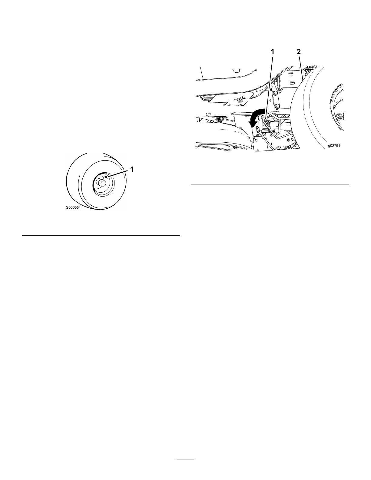
ReleasingtheElectricBrake
Theelectricbrakereleasesbymanuallyrotatingthelinkarms
forward.Oncetheelectricbrakeisenergized,thebrakeresets.
Figure42
1.Brakelinkarmontheelectric-brake-controlmodule
2.Leftreartire
1.TurntheignitionkeytotheOFFpositionordisconnect
thebattery.
1.Valvestem
Figure41
2.Locatetheshaftontheelectricbrakewherethe
brake-linkarmsareconnected(Figure42).
3.Rotatetheshaftforwardtoreleasethebrake.
34
Page 35
HydraulicSystem
Maintenance
HydraulicSystemFluidSpecication
OilType:ToroHYPR-OIL®500or20W -50motoroil.
SystemCapacity:approximately4.5L(152oz)witha
lterchange.
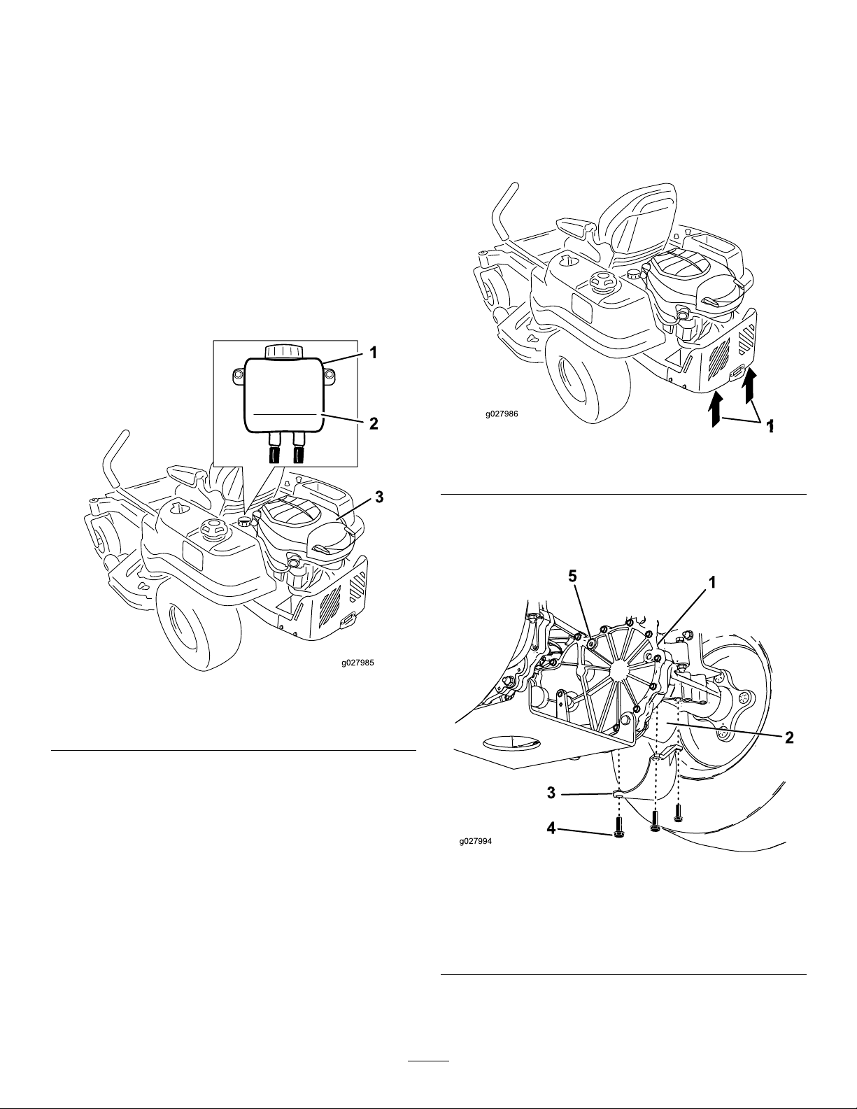
CheckingtheHydraulicFluid Level
ServiceInterval:Every25hours
Checkthehydraulicuidlevelintheexpansionreservoirand
ifnecessaryaddthespecieduidtotheFullColdline.
RemovingtheHydraulicSystemFilters
1.Shutofftheengine,waitforallmovingpartstostop,
andallowenginetocool.Removethekeyandengage
theparkingbrake.
2.Raisetherearofthemachineandsupportitwithjack
stands(orequivalentsupport)justhighenoughto
allowdrivewheelstoturnfreely.
Figure44
Figure43
1.Expansionreservoir3.Engine
2.FullColdline
ChangingtheHydraulic SystemFluidandFilters
ServiceInterval:Aftertherst50hours
Every400hours
Important:Repeatthebleedingprocessuntilthe
uidremainsattheFullColdlineinthereservoirafter
purging.
can r esult in ir r epara ble dama ge to the transaxle dri v e
system.
F ailur e to pr oper l y perf or m this pr ocedur e
1.Jackingpoints
3.Locatethelterandlterguardsoneachtransaxle
drivesystem(Figure45).Removethe3screwssecuring
thelterguardandguard.
Figure45
Rightsideshown
1.Transaxledrive
2.Oillter
3.Filterguard
4.Screws
5.Ventplug
Note:Changethelteranduidatthesametime.Donot
reuseuid.Onceyouinstallthenewlterandadduid,
purgeanyairinthesystem.
4.Carefullycleanareaaroundthelters.
35
Page 36

Note:Ensurethatnodirtorcontaminationenters
B
A
C D
E
F
3/4
g027477
thehydraulicsystem.
5.Placeacontainerbelowtheltertocatchtheuidthat
drainswhenyouremovethelterandventplugs.
6.Locateandremovetheventplugoneachtransmission
7.Unscrewtheltertoremoveandallowtheuidto
drainfromdrivesystem.
8.Repeatthisprocedurefortheotherlter.
InstallingtheHydraulicSystemFilters
Note:Torquetheplugto20.3N∙m(180in-lb).
6.Continuetoaddoilthroughtheexpansionreservoir
untilitreachestheFullColdlineontheexpansion
reservoir.
7.ProceedtotheBleedingtheHydraulicSystem(page
36).
Important:Failuretobleedthehydraulicsystem
afterchangingthehydraulicltersandoilcan
resultinirreparabledamagetothetransaxledrive
system.
1.InstalltheltersasshowninFigure46.
2.Installthelterguardsovereachlteraspreviously
removed.
Figure46
BleedingtheHydraulicSystem
1.Sitontheseat.Starttheengine,movethethrottle
controltothe1/2-throttleposition,anddisengagethe
parkingbrake.
A.Movethebypassleversintothepushingthe
machineposition;refertothePushingthe
MachinebyHand(page21).
B.Withthebypassvalvesopenandtheengine
running,slowlymovethemotion-controlleversin
bothforwardandreverse(5or6times).
C.Movethebypassleversintotheoperatingthe
machineposition.
D.Withthebypassvalveclosedandtheengine
running,slowlymovethemotion-controlleversin
bothforwardandreversedirections(5to6times).
E.Stoptheengineandchecktheoillevelinthe
expansionreservoir.Addthespeciedoilasuntil
itreachestheFullColdlineontheexpansion
reservoir.
2.Repeatstep1untilalltheairiscompletelypurgedfrom
thesystem.
Note:Whenthetransaxleoperatesatnormalnoise
levelsandmovessmoothlyforwardandreverseat
normalspeeds,thenthetransaxleisconsideredpurged.
3.Checktheoillevelintheexpansionreservoiranal
time.AddthespeciedoilasuntilitreachestheFull
Coldlineontheexpansionreservoirifnecessary.
Note:Usethe3screwstosecurethelterguards.
3.Verifythattheventplugsareremovedbeforeadding
theuid.
4.Slowlypourthespecieduidthroughexpansion
reservoiruntiloilcomesoutof1vent-plughole.Install
thatventplug.
Note:Torquetheplugto20.3N∙m(180in-lb).
5.Continuetoaddoilthroughtheexpansionreservoir
untiloilcomesoutoftheremainingventplugholeon
thesecondtransmission.Installthatventplug.
36
Page 37
MowerMaintenance
G014972
1
2
3
ServicingtheCuttingBlades
Maintainsharpbladesthroughoutthecuttingseason,because
sharpbladescutcleanlywithouttearingorshreddingthe
grassblades.Tearingandshreddingthegrassturnsitbrown
attheedges,whichslowsgrowthandincreasesthechance
ofdisease.
Checkthecuttingbladesdailyforsharpnessandforany
wearordamage.Filedownanynicksandsharpenthe
bladesasnecessary.Ifabladeisdamagedorworn,replace
itimmediatelywithagenuineT ororeplacementblade.For
convenientsharpeningandreplacement,keepextrablades
onhand.
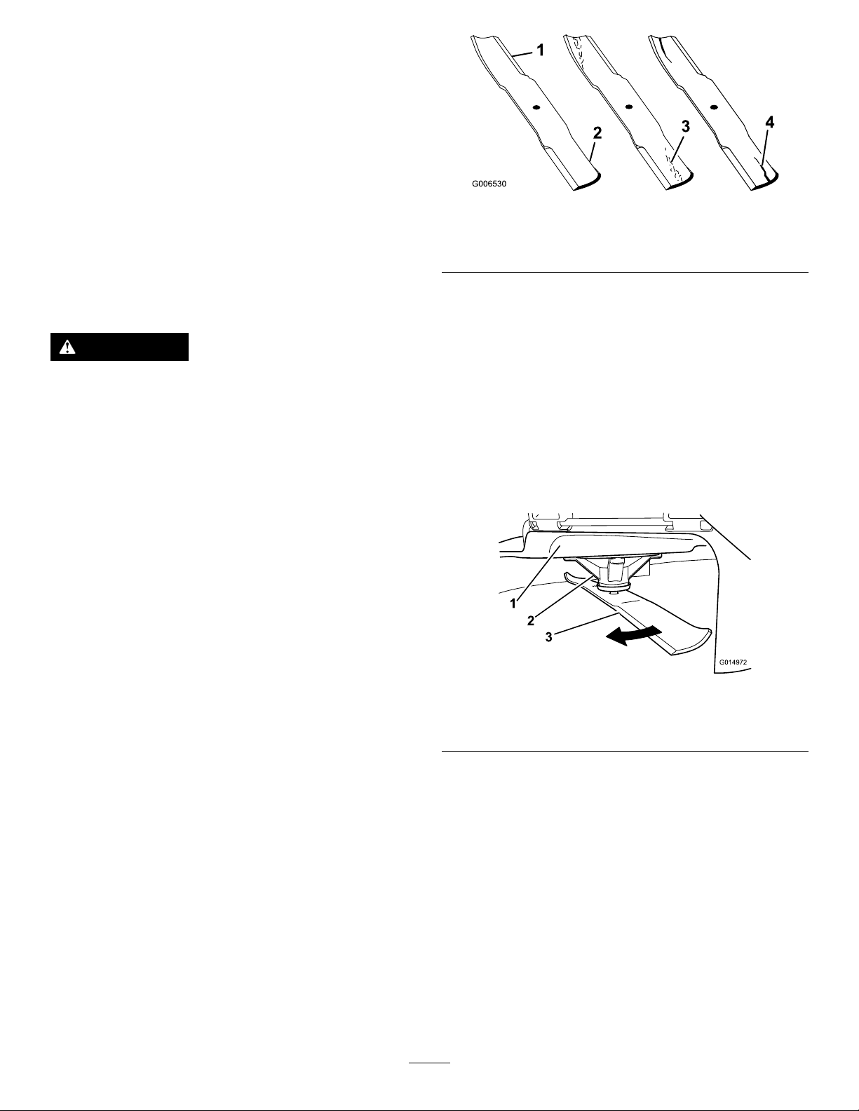
Figure47
1.Cuttingedge3.Wear/slotforming
2.Curvedarea
4.Damage
CheckingforBentBlades
WARNING
Awornordamagedbladecanbreakandapiece
ofthebladecouldbethrownatyouorbystanders,
resultinginseriouspersonalinjuryordeath.
•Inspectthebladeperiodicallyforwearor
damage.
•Replaceawornordamagedblade.
BeforeInspectingorServicingthe
Blades
Parkthemachineonalevelsurface,disengagethe
blade-controlswitch,movethemotion-controlleversoutward
tothePARKposition,shutofftheengine,andremovethekey .
InspectingtheBlades
ServiceInterval:Beforeeachuseordaily—Checkthe
cuttingblades.
1.Inspectthecuttingedges(Figure47).
Note:Iftheedgesarenotsharporhavenicks,remove
andsharpentheblades;refertoSharpeningtheBlades
(page39).
Note:Parkthemachineonalevelsurfaceforthefollowing
procedure.
1.Raisethemowerdecktothehighestheight-of-cut
position.
2.Whilewearingthicklypaddedgloves,orotheradequate
handprotection,slowlyrotatethebladetobemeasured
intoapositionthatallowsyoutoeffectivelymeasure
thedistancebetweenthecuttingedgeandthelevel
surfacethatthemachineison(Figure48).
Figure48
1.Deck3.Blade
2.Spindlehousing
2.Inspecttheblades,especiallythecurvedarea(Figure
47).
Note:Ifyounoticeanydamage,wear,oraslot
forminginthisarea(items3and4inFigure47),
immediatelyinstallanewblade.
37
Page 38

3.Measurefromthetipofthebladetotheatsurface
G014973
1
2
3
G014974
1
2
3
G014973
1
2
3
(Figure49).
Figure49
1.Blade(inpositionformeasuring)
2.Levelsurface
3.Measureddistancebetweenbladeandthesurface(A)
4.Rotatethesameblade180degreessothattheopposing
cuttingedgeisnowinthesameposition(Figure50).
Figure51
1.Oppositebladeedge(inpositionformeasuring)
2.Levelsurface
3.Secondmeasureddistancebetweenbladeandsurface(B)
A.IfthedifferencebetweenAandBisgreaterthan
3mm(1/8inch),replacethebladewithanew
blade;refertoRemovingtheBlades(page39)and
InstallingtheBlades(page39).
Note:Ifyoureplaceabentbladewithanew
bladeandthedimensionobtainedcontinuesto
exceed3mm(1/8inch),thebladespindlecould
bebent.ContactanAuthorizedToroDealerfor
service.
Figure50
1.Blade(sidepreviouslymeasured)
2.Measurement(positionusedpreviously)
3.Opposingsideofbladebeingmovedintomeasurement
position
5.Measurefromthetipofthebladetotheatsurface
(Figure51).
Note:Thevarianceshouldbenomorethan3mm
(1/8inch).
B.Ifthevarianceiswithinconstraints,movetothe
nextblade.
6.Repeatsteps1through5foreachblade.
38
Page 39

RemovingtheBlades
Replaceabladeifithitsasolidobject,ifthebladeisoutof
balance,orifthebladeisbent.Forbestperformanceand
continuedsafetyconformanceofthemachine,usegenuine
Tororeplacementblades.Replacementbladesmadebyother
manufacturersmayresultinnon-conformancewithsafety
standards.
Figure54
1.Blade2.Balancer
1.Holdthebladeendusingaragorthicklypaddedglove.
2.Removethebladebolt,curvedwasher,andbladefrom
thespindleshaft(Figure52).
Figure52
1.Sailareaoftheblade3.Curvedwasher
2.Blade4.Bladebolt
SharpeningtheBlades
1.Usealetosharpenthecuttingedgeatbothendsof
theblade(Figure53).
3.Repeatthisprocedureuntilthebladeisbalanced.
InstallingtheBlades
1.Installthebladeontothespindleshaft(Figure52).
Important:Thecurvedpartoftheblademust
pointupwardtowardtheinsideofthemowerto
ensurepropercutting.
2.Installthecurvedwasher(cuppedsidetowardthe
blade)andthebladebolt(Figure52).
3.Torquethebladeboltto47to88N∙m(35to65ft-lb).
LevelingtheMowerDeck
Ensurethatthemowerdeckislevelanytimeyouinstallthe
mowerdeckorwhenyouseeanunevencutonyourlawn.
Checkthemowerdeckforbentbladespriortoleveling;
removeandreplaceanybentblades;refertoCheckingfor
BentBlades(page37)beforecontinuing.
Levelthemowerdeckside-to-sidebeforeadjustingthe
front-to-rearslope.
Note:Maintaintheoriginalangle.
Note:Thebladeretainsitsbalanceifyouremovethe
sameamountofmaterialfrombothcuttingedges.
Figure53
1.Sharpenattheoriginalangle.
2.Checkthebalanceofthebladebyputtingitonablade
balancer(Figure54).
Note:Ifthebladestaysinahorizontalposition,the
bladeisbalancedandreadytouse.
Note:Ifthebladeisnotbalanced,lesomemetaloff
onlytheendofthesailarea(Figure53).
Requirements:
•Themachinemustbeonalevelsurface.
•All4tiresmustbeproperlyinated;refertoChecking
theTirePressure(page34).
LevelingfromSidetoSide
1.Parkthemachineonalevelsurfaceanddisengagethe
blade-controlswitch.
2.Movethemotion-controlleversoutwardtothePARK
position,shutofftheengine,removethekey,and
waitforallmovingpartstostopbeforeleavingthe
operatingposition.
3.Settheheight-of-cutlevertomiddleposition.
4.Carefullyrotatetheblade(s)sothattheyareallside
toside(Figure55).
39
Page 40
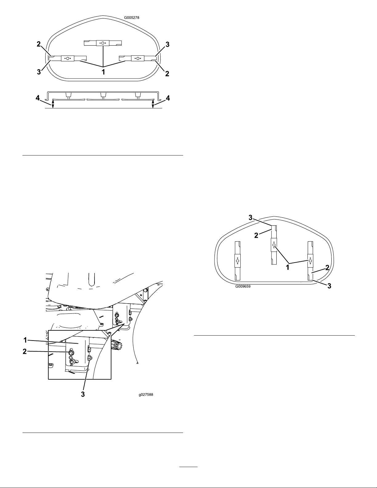
G005278
1
2
2
3
3
4
4
10.Continuelevelingthedeckbycheckingthefront-to-rear
G009659
1
2
3
2
3
bladeslope;refertoAdjustingtheFront-to-RearBlade
Slope(page40).
AdjustingtheFront-to-RearBlade
Slope
Checkthefront-to-rearbladelevelanytimeyouinstallthe
mower.Ifthefrontofthemowerismorethan7.9mm
(5/16inch)lowerthantherearofthemower,adjusttheblade
level.
Figure55
1.Bladessidetoside
2.Sailareaoftheblade4.measurefromthetipofthe
3.Outsidecuttingedges
bladetotheatsurface
here.
5.Measurebetweentheoutsidecuttingedgesandtheat
surface(Figure55).
Note:Ifbothmeasurementsarenotwithin5mm
(3/16inch),anadjustmentisrequired;continuewith
thisprocedure.
6.Movetotheleftsideofthemachine.
7.Loosenthesidelockingnut.
8.Raiseorlowertheleftsideofthemowerdeckby
rotatingtherearlockingnut.(Figure56).
Note:Rotatetherearlockingnutclockwiseto
raisethemowerdeck;rotatetherearlockingnut
counter-clockwisetolowerthemowerdeck.
1.Parkthemachineonalevelsurfaceanddisengagethe
blade-controlswitch.
2.Movethemotion-controlleversoutwardtothePARK
position,shutofftheengine,removethekey,and
waitforallmovingpartstostopbeforeleavingthe
operatingposition.
3.Settheheight-of-cutlevertomiddleposition.
Note:Checkandadjusttheside-to-sidebladelevel
ifyouhavenotcheckedthesetting;refertoLeveling
fromSidetoSide(page39).
4.Carefullyrotatethebladessothattheyarefacingfront
torear(Figure57).
Figure57
1.Bladesfronttorear3.Measurefromthetipofthe
2.Outsidecuttingedges
bladetotheatsurface
here.
5.Measurefromthetipofthefrontbladetotheat
surface,andthetipoftherearbladetotheatsurface
(Figure57).
Note:Ifthefrontbladetipisnot1.6to7.9mm(1/16
to5/16inch)lowerthantherearbladetip,adjustthe
frontlocknut.
Figure56
1.Hangerbracket3.Rearlockingnut
2.Sidelockingnut
6.Toadjustthefront-to-rearbladeslope,rotatethe
adjustmentnutinthefrontofthemower(Figure58).
Note:Toraisethefrontofthemower,tightenthe
adjustmentnut.Tolowerthefrontofthemower,
loosentheadjustmentnut.
9.Checktheside-to-sideadjustmentsagain.Repeatthis
procedureuntilthemeasurementsarecorrect.
40
Page 41

G014634
1
2
3
Figure58
G014635
1
2
3
2
2
3
G005077
1
2
2
3
1.Adjustingrod3.Locknut
2.Adjustingblock
7.Afteradjustment,checkthefront-to-rearslopeagain,
continueadjustingthenutuntilthefrontbladetipis
1.6to7.9mm(1/16to5/16inch)lowerthantherear
bladetip(Figure57).
8.Whenthefront-to-rearbladeslopeiscorrect,checkthe
side-to-sidelevelofthemoweragain,refertoLeveling
fromSidetoSide(page39).
RemovingtheMower
1.Parkthemachineonalevelsurfaceanddisengagethe
blade-controlswitch.
2.Movethemotion-controlleversoutwardtothePARK
position,shutofftheengine,removethekey,and
waitforallmovingpartstostopbeforeleavingthe
operatingposition.
3.Lowertheheight-of-cutlevertothelowestposition.
4.Removethehairpincotterfromthefrontsupportrod
andremovetherodfromthedeckbracket(Figure59).
Figure59
1.Frontsupportrod3.Deckbracket
2.Lockingnut
5.Carefullylowerthefrontofthemowerdecktothe
ground.
6.Liftthemowerdeckandhangerbracketsclearof
therearliftrodandlowerthemowercarefullytothe
ground(Figure60).
Figure60
1.Mowerdeck
2.Hangerbracket
7.Slidethemowerdeckrearwardtoremovethemower
beltfromtheenginepulley.
8.Slidethemowerdeckoutfromunderneaththe
3.Rearliftrod
machine.
41
Page 42

Note:Retainallpartsforfutureinstallation.
G005192
1
2
3
4
5
6
7
InstallingtheMower
1.Parkthemachineonalevelsurfaceanddisengagethe
blade-controlswitch.
2.Movethemotion-controlleversoutwardtothePARK
position,shutofftheengine,removethekey,and
waitforallmovingpartstostopbeforeleavingthe
operatingposition.
3.Slidethemowerunderthemachine.
4.Lowertheheight-of-cutlevertothelowestposition.
5.Lifttherearofthemowerdeckandguidethehanger
bracketsovertherearliftrod(Figure60).
6.Attachthefrontsupportrodtothemowerdeckwith
theclevispinandhairpincotter(Figure59).
7.Installthemowerbeltontotheenginepulley;referto
ReplacingtheMowerBelt(page43).
Figure61
1.Mowerdeck
2.Grassdeector6.Nut(3/8inch)
3.Grass-deectorbracket7.Shortstandoff
4.Rod
5.Spring
ReplacingtheGrassDeector
ServiceInterval:Beforeeachuseordaily—Inspectthegrass
deectorfordamage.
WARNING
Anuncovereddischargeopeningcouldallowthe
lawnmowertothrowobjectsatyouorbystanders,
resultinginseriousinjury.Also,contactwiththe
bladecouldoccur.
Neveroperatethemachinewithoutthegrass
deector,thedischargecover,orthegrass-collection
systeminplace.
Inspectthegrassdeectorfordamagebeforeeachuse.
Replaceanydamagedpartsbeforeuse.
1.Removethenut(3/8inch)fromtherodunderthe
mower(Figure61).
2.Slidetherodoutoftheshortstandoff,spring,and
grassdeector(Figure61).
3.Removethedamagedorworngrassdeector.
4.Replacethegrassdeector(Figure61).
5.Slidetherod(straightend)throughtherear
grass-deectorbracket.
6.Placethespringontherod,withtheendwiresdown
andbetweenthegrass-deectorbrackets.
7.Sliderodthroughthesecondgrass-deectorbracket
(Figure61).
8.Inserttherodatthefrontofthegrassdeectorinto
theshortstandoffonthedeck.
9.Securetherearendoftherodintothemowerwitha
nut(3/8inch)asshowninFigure61.
Important:Thegrassdeectormustbe
spring-loadedandinthedownposition.Liftthe
deectoruptotestthatitsnapstothefulldown
position.
42
Page 43
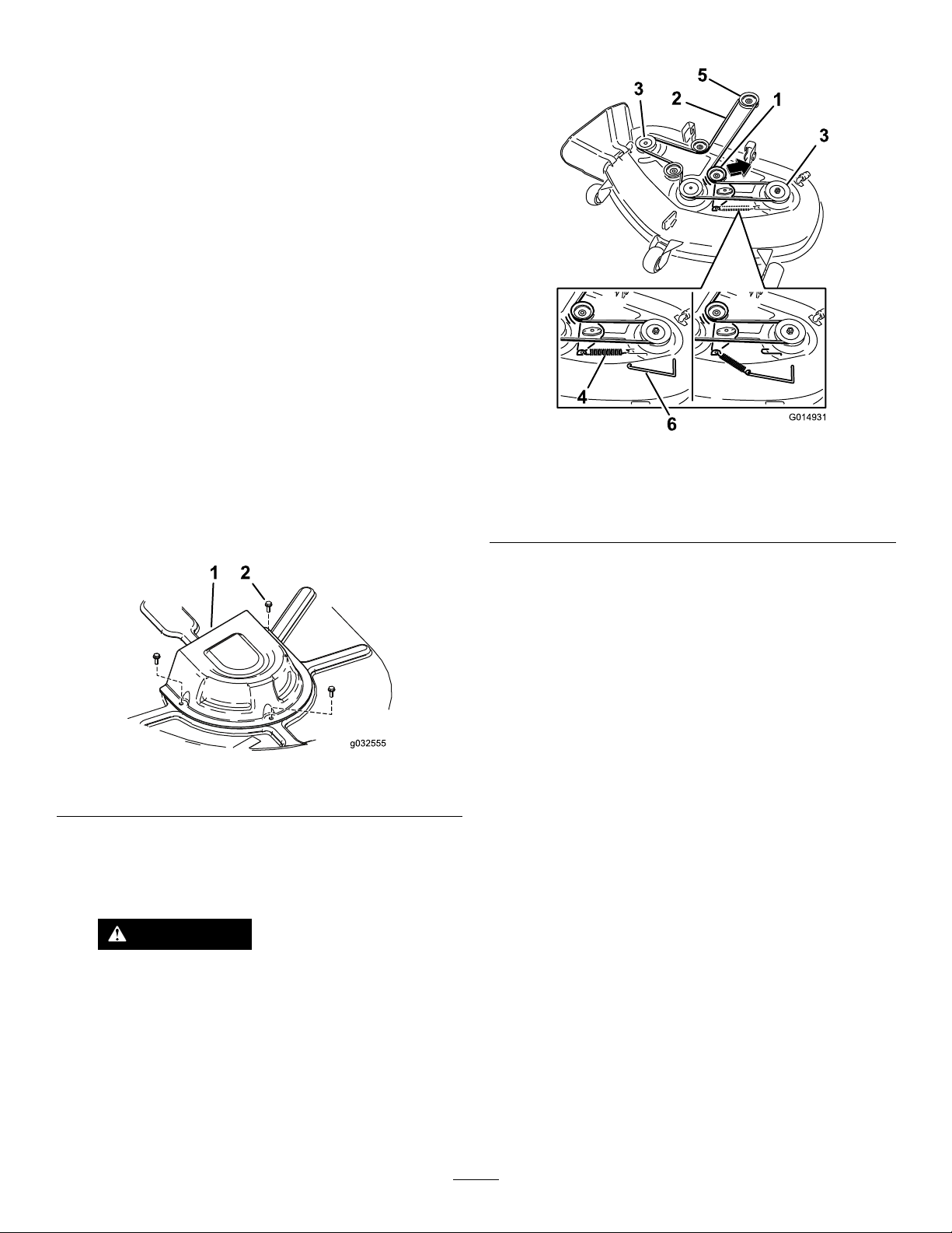
MowerBeltMaintenance
G014931
1
2
3
3
4
5
6
InspectingtheBelts
ServiceInterval:Every25hours—Checkthebeltsforwear
orcracks.
Checkthebeltsforcracks,frayededges,burnmarks,orany
otherdamage.Replacedamagedbelts.
ReplacingtheMowerBelt
Thesignsofawornbeltincludesquealingwhilethebeltis
rotating,bladesslippingwhilecuttinggrass,andfrayededges,
burnmarks,andcracksonthebelt.Replacethemowerbeltif
anyoftheseconditionsareevident.
1.Parkthemachineonalevelsurfaceanddisengagethe
blade-controlswitch.
2.Movethemotion-controlleversoutwardtothePARK
position,shutofftheengine,removethekey,and
waitforallmovingpartstostopbeforeleavingthe
operatingposition.
3.Settheheight-of-cutatthelowestcuttingpositionof
38mm(1-1/2inches).
8.Installthepulleycovers(Figure62).
Figure63
1.Idlerpulley
2.Mowerbelt5.Enginepulley
3.Outsidepulley6.Spring-removaltool
4.Spring
4.Removethepulleycovers(Figure62).
Figure62
1.Cover2.Screw
5.Usingaspring-removaltool(ToroPartNo.92-5771),
removetheidlerspringfromthedeckhooktoremove
tensionontheidlerpulley ,androllthebeltoffthe
pulleys(Figure63).
WARNING
Thespringisundertensionwheninstalled
andcancausepersonalinjury.
Becarefulwhenremovingthebelt.
6.Routethenewbeltaroundtheenginepulleyand
mowerpulleys(Figure63).
7.Usingaspring-removaltool,installtheidlerspringover
thedeckhook,andplacetensionontheidlerpulley
andmowerbelt(Figure63).
43
Page 44

Cleaning
G020098
2
4
1
2
3
4
8.Turnthewateroffandremovethecouplingfromthe
washouttting.
WashingtheUndersideofthe Mower
ServiceInterval:Aftereachuse—Cleanthemower-deck
housing.
Washtheundersideofthemoweraftereachusetoprevent
grassbuildupforimprovedmulchactionandclipping
dispersal.
Important:Youcanwashthemachinewithmild
detergentandwater.Donotpressurewashthemachine.
Avoidexcessiveuseofwater,especiallynearthecontrol
panel,undertheseat,andaroundtheengine,hydraulic
pumps,andmotors.
1.Parkthemachineonalevelsurfaceanddisengagethe
blade-controlswitch.
2.Movethemotion-controlleversoutwardtothePARK
position,shutofftheengine,removethekey,and
waitforallmovingpartstostopbeforeleavingthe
operatingposition.
3.Attachthehosecouplingtotheendofthe
mower-washoutttingandturnthewateronhigh
(Figure64).
Note:Ifthemowerisnotcleanafterasinglewashing,
soakitandletitstandfor30minutes.Then,repeat
theprocess.
9.Runthemoweragainfor1to3minutestoremove
excesswater.
WARNING
Abrokenormissingwashoutttingcould
exposeyouandotherstothrownobjectsor
bladecontact,causinginjuryordeath.
•Replacebrokenormissingwashouttting
immediatelybeforeusingmoweragain.
•Neverputyourhandsorfeetunderthe
mowerorthroughopeningsinthemower.
Note:Spreadpetroleumjellyonthewashouttting
O-ringtomakethecouplingslideoneasierandto
protecttheO-ring.
Figure64
1.Washouttting3.O-ring
2.Hose
4.Lowerthemowertothelowestheight-of-cut.
5.Sitontheseatandstarttheengine.
6.Engagetheblade-controlswitchandletthemowerrun
for1to3minutes.
7.Disengagetheblade-controlswitch,shutoffthe
engine,removetheignitionkey,andwaitforallmoving
partstostop.
4.Coupling
44
Page 45

Storage
CleaningandStorage
1.Disengagetheblade-controlswitch,movethe
motion-controlleversoutwardtothePARKposition,
shutofftheengine,andremovethekey .
2.Removegrassclippings,dirt,andgrimefromthe
externalpartsoftheentiremachine,especiallythe
engine.Cleandirtandchafffromtheoutsideofthe
enginecylinderheadnsandblowerhousing.
Important:Youcanwashthemachinewithmild
detergentandwater.Donotpressurewashthe
machine.Avoidexcessiveuseofwater,especially
nearthecontrolpanel,undertheseat,aroundthe
engine,hydraulicpumps,andmotors.
3.Servicetheaircleaner;refertoServicingtheAir
Cleaner(page27).
4.Greaseandoilthemachine;refertoLubrication(page
26).
5.Changetheengineoilandlter;refertoChangingthe
EngineOilandtheEngine-OilFilter(page28).
plug(s)removedfromtheengine,pour2tablespoons
ofengineoilintothesparkplughole.Usethestarter
tocranktheengineanddistributetheoilinsidethe
cylinder.Installthesparkplug(s).Donotinstallthe
wireonthesparkplug(s).
11.Cleananydirtandchafffromthetopofthemower.
12.Scrapeanyheavybuildupofgrassanddirtfromthe
undersideofthemower,thenwashthemowerwith
agardenhose.
13.Checktheconditionofthedriveandmowerbelts.
14.Checkandtightenallbolts,nuts,andscrews.Repairor
replaceanypartthatiswornordamaged.
15.Paintallscratchedorbaremetalsurfaces.Paintis
availablefromyourAuthorizedServiceDealer.
16.Storethemachineinaclean,drygarageorstoragearea.
Removethekeyfromtheignitionswitchandkeepit
inamemorableplace.Coverthemachinetoprotect
itandkeepitclean.
6.Checkthetirepressure;refertoCheckingtheTire
Pressure(page34).
7.Chargethebattery;refertoChargingtheBattery(page
32).
8.Checktheconditionoftheblades;refertoServicing
theCuttingBlades(page37).
9.Preparethemachineforstoragewhennon-useoccurs
over30days.Preparethemachineforstorageas
follows.
A.Addapetroleumbasedstabilizer/conditionerto
thefuelinthetank.Followthemixinginstructions
fromthestabilizermanufacturer.Donotusean
alcoholbasedstabilizer(ethanolormethanol).
Note:Afuelstabilizer/conditionerismost
effectivewhenmixedwithfreshgasolineandused
atalltimes.
B.Runtheenginetodistributetheconditionedfuel
throughthefuelsystem(5minutes).
C.Shutofftheengine,waitforittocool,anddrain
thefueltank.
D.Restarttheengineandrunituntilitstops.
E.Startandruntheengineuntilitdoesnotstart.
F.Disposeoffuelproperly .Recyclepursuantto
localcodes.
Important:Donotstoregasolinewith
stabilizer/conditionerover90days.
10.Removethesparkplug(s)andcheckitscondition;refer
toServicingtheSparkPlug(page29).Withthespark
45
Page 46

Troubleshooting
Problem
Thefueltankisshowingsignsof
collapsingorthemachineisshowingsigns
offrequentlyrunningoutoffuel.
Theengineoverheats.
Thestarterdoesnotcrank.
Theenginedoesnotstart,startshard,or
failstokeeprunning.
PossibleCauseCorrectiveAction
1.Theaircleanerpaperelementis
clogged.
1.Theengineloadisexcessive.1.Reducethegroundspeed.
2.Theoillevelinthecrankcaseislow.2.Addoiltothecrankcase.
3.Thecoolingnsandairpassages
undertheengineblowerhousingare
plugged.
4.Theaircleanerisdirty.
5.Dirt,water,orstalefuelisinthefuel
system.
1.Theblade-controlswitchisengaged.1.Movetheblade-controlswitchto
2.Themotion-controlleversarenotin
thePARKposition.
3.Thebatteryisdead.
4.Theelectricalconnectionsare
corrodedorloose.
5.Afuseisblown.5.Replacethefuse.
6.Arelayorswitchisdamaged.
1.Thefueltankisempty.1.Fillthefueltank.
2.Theaircleanerisdirty.
3.Thesparkplugwire(s)islooseor
disconnected.
4.Thesparkplug(s)ispitted,fouled,or
thegapisincorrect.
5.Thereisdirtinfuellter .5.Replacethefuellter.
6.Dirt,water,orstalefuelisinfuel
system.
7.Thereisincorrectfuelinthefueltank.7.Drainthetankandreplacethefuelwith
8.Theoillevelinthecrankcaseislow.8.Addoiltothecrankcase.
1.Cleanthepaperelement.
3.Removetheobstructionfromthe
coolingnsandairpassages.
4.Cleanorreplacetheair-cleaner
element.
5.ContactanAuthorizedServiceDealer.
Disengaged.
2.Movethemotion-controllevers
outwardtothePARKposition.
3.Chargethebattery.
4.Checktheelectricalconnectionsfor
goodcontact.
6.ContactanAuthorizedServiceDealer.
2.Cleanorreplacetheair-cleaner
element.
3.Installthewire(s)onthesparkplug.
4.Installanew,correctlygappedspark
plug(s).
6.ContactanAuthorizedServiceDealer.
thepropertype.
Theenginelosespower.
1.Theengineloadisexcessive.1.Reducethegroundspeed.
2.Theaircleanerisdirty.
3.Theoillevelinthecrankcaseislow.3.Addoiltothecrankcase.
4.Thecoolingnsandairpassages
undertheengineblowerhousingare
plugged.
5.Thesparkplug(s)ispitted,fouled,or
thegapisincorrect.
6.Thefuel-tankventisblocked.6.ContactanAuthorizedServiceDealer.
7.Thereisdirtinthefuellter.7.Replacethefuellter.
8.Dirt,water,orstalefuelisinthefuel
system.
9.Thereisincorrectfuelinthefueltank.9.Drainthetankandreplacethefuelwith
2.Cleantheair-cleanerelement.
4.Removetheobstructionfromthe
coolingnsandairpassages.
5.Installanew,correctlygappedspark
plug(s).
8.ContactanAuthorizedServiceDealer.
thepropertype.
46
Page 47

Problem
PossibleCauseCorrectiveAction
Themachinedoesnotdrive.
Thereisanabnormalvibration.
Thecuttingheightisuneven.
Thebladesdonotrotate.
1.Thebypassvalvesareopen.
2.Thetractionbeltsareworn,loose,or
broken.
3.Thetractionbeltsareoffthepulleys.3.ContactanAuthorizedServiceDealer.
4.Thetransmissionhasfailed.4.ContactanAuthorizedServiceDealer.
1.Theengine-mountingboltsareloose.1.Tightentheengine-mountingbolts.
2.Theenginepulley,idlerpulley ,orblade
pulleyisloose.
3.Theenginepulleyisdamaged.
4.Thecuttingblade(s)is/arebentor
unbalanced.
5.Ablade-mountingboltisloose.5.Tightentheblade-mountingbolt.
6.Abladespindleisbent.
1.Theblade(s)isnotsharp.1.Sharpentheblade(s).
2.Acuttingblade(s)is/arebent.2.Installanewcuttingblade(s).
3.Themowerisnotlevel.
4.Ananti-scalpwheelisnotsetcorrectly.4.Adjusttheanti-scalpwheelheight.
5.Theundersideofthemowerisdirty.5.Cleantheundersideofthemower.
6.Thetirepressureisincorrect.6.Adjustthetirepressure.
7.Abladespindleisbent.
1.Thedrivebeltisworn,loose,orbroken.1.Installanewdrivebelt.
2.Thedrivebeltisoffthepulley.
3.Thepower-takeoff(PTO)switchor
PTOclutchisfaulty.
4.Themowerbeltisworn,loose,or
broken.
1.Closethetowvalves.
2.ContactanAuthorizedServiceDealer.
2.Tightentheappropriatepulley .
3.ContactanAuthorizedServiceDealer.
4.Installanewcuttingblade(s).
6.ContactanAuthorizedServiceDealer.
3.Levelthemowerfromside-to-sideand
front-to-rear.
7.ContactanAuthorizedServiceDealer.
2.Installthedrivebeltandcheckthe
adjustingshaftsandbeltguidesforthe
correctposition.
3.ContactanAuthorizedServiceDealer.
4.Installanewmowerbelt.
47
Page 48

Schematics
ElectricalDiagram(Rev .A)
48
Page 49

Notes:
49
Page 50

Notes:
50
Page 51

Notes:
51
Page 52

LimitedWarranty(seewarrantyperiodsbelow)
TheToroWarranty
TimeCutter
and
TITAN
Mowers
ConditionsandProductsCovered
TheT oroCompanyanditsafliate,ToroWarrantyCompany ,pursuanttoan
agreementbetweenthem,jointlypromisetorepairtheT oroProductslisted
belowifdefectiveinmaterialsorworkmanship.
Thefollowingtimeperiodsapplyfromthedateofpurchasebytheoriginal
owner:
ProductsWarrantyPeriod
TimeCutterandMXMowers
•Engines
1
Residentialuse
—ResidentialuseKawasaki–3years
2
–3years
Kohler–3years
Toro–3years
TimeCutterandMXMowersCommercialuse30days
•Engines
1
—Commercialuse
Kawasaki–3years
Kohler–90days
Toro–90days
TITANSWandZSSeriesMowers–
ResidentialorCommercialuse
•Engines
1
—Residentialor
Commercialuse
•Frame
TITANMXSeriesMowers–
ResidentialorCommercialuse
•Engines
1
—Residentialor
Commercialuse
•Frame
3yearsor300hours
Kawasaki–3years
Lifetime(originalowneronly)
4yearsor400hours
Kawasaki–3years
Lifetime(originalowneronly)
3
4
3
4
AllMowers
•Attachments1year
•Battery90daysPartsandLabor
1yearPartsonly
•BeltsandTires90days
1
SomeenginesusedonToroProductsarewarrantedbytheenginemanufacturer.
2
Residentialusemeansuseoftheproductonthesamelotasyourhome.Useatmorethanone
locationisconsideredcommercialuseandthecommercialusewarrantywouldapply.
3
Whicheveroccursrst.
4
LifetimeFrameW arranty-Ifthemainframe,consistingofthepartsweldedtogethertoformthe
tractorstructurethatothercomponentssuchastheenginearesecuredto,cracksorbreaksin
normaluse,itwillberepairedorreplaced,atToro'soption,underwarrantyatnocostforpartsand
labor.Framefailureduetomisuseorabuseandfailureorrepairrequiredduetorustorcorrosion
arenotcovered.
Warrantymaybedeniedifthehourmeterisdisconnected,altered,or
showssignsofbeingtamperedwith.
OwnerResponsibilities
YoumustmaintainyourToroProductbyfollowingthemaintenance
proceduresdescribedintheOperator'sManual.Suchroutinemaintenance,
whetherperformedbyadealerorbyyou,isatyourexpense.
InstructionsforObtainingWarrantyService
IfyouthinkthatyourT oroProductcontainsadefectinmaterialsor
workmanship,followthisprocedure:
1.ContactanyAuthorizedT oroServiceDealertoarrangeserviceat
theirdealership.Tolocateadealerconvenienttoyou,accessourweb
siteatwww .Toro.com.Youmayalsocallthenumberslistedinitem#3
tousethe24-hourT oroDealerlocatorsystem.
2.Bringtheproductandyourproofofpurchase(salesreceipt)tothe
ServiceDealer.Thedealerwilldiagnosetheproblemanddetermineif
itiscoveredunderwarranty.
3.IfforanyreasonyouaredissatisedwiththeServiceDealer’s
analysisorwiththeassistanceprovided,contactusat:
ToroWarrantyCompany
CustomerCareDepartment,RLCDivision
811 1LyndaleAvenueSouth
Bloomington,MN55420-1196
Tollfreeat866-216-6029(U.S.customers)
Tollfreeat866-216-6030(Canadiancustomers)
ItemsandConditionsNotCovered
Thereisnootherexpresswarrantyexceptforspecialemissionsystem
coverageandenginewarrantycoverageonsomeproducts.Thisexpress
warrantydoesnotcoverthefollowing:
•Costofregularmaintenanceserviceorparts,suchaslters,fuel,
lubricants,oilchanges,sparkplugs,airltersbladesharpeningorworn
blades,cable/linkageadjustments,orbrakeandclutchadjustments
•Componentsfailingduetonormalwear
•Anyproductorpartwhichhasbeenalteredormisusedorneglected
orrequiresreplacementorrepairduetoaccidentsorlackofproper
maintenance
•Pickupanddeliverycharges
•RepairsorattemptedrepairsbyanyoneotherthananAuthorizedToro
ServiceDealer
•Repairsnecessaryduetofailuretofollowrecommendedfuel
procedure(consultOperator'sManualformoredetails)
–Removingcontaminantsfromthefuelsystemisnotcovered
–Useofoldfuel(morethanonemonthold)orfuelwhichcontains
morethan10%ethanolormorethat15%MTBE
–Failuretodrainthefuelsystempriortoanyperiodofnon-use
overonemonth
GeneralConditions
AllrepairscoveredbythesewarrantiesmustbeperformedbyanAuthorized
ToroServiceDealerusingT oroapprovedreplacementparts.
NeitherTheToroCompanynorToroWarrantyCompanyisliablefor
indirect,incidentalorconsequentialdamagesinconnectionwiththe
useoftheToroProductscoveredbythiswarranty,includingany
costorexpenseofprovidingsubstituteequipmentorserviceduring
reasonableperiodsofmalfunctionornon-usependingcompletionof
repairsunderthiswarranty.
Allimpliedwarrantiesofmerchantability(thattheproductistfor
ordinaryuse)andtnessforuse(thattheproductistforaparticular
purpose)arelimitedtothedurationoftheexpresswarranty.
Somestatesdonotallowexclusionsofincidentalorconsequential
damages,orlimitationsonhowlonganimpliedwarrantylasts,sothe
aboveexclusionsandlimitationsmaynotapplytoyou.
Thiswarrantygivesyouspeciclegalrights,andyoumayalsohaveother
rightswhichvaryfromstatetostate.
CountriesOtherthantheUnitedStatesorCanada
ThiswarrantyisnotvalidinMexico.CustomerswhohavepurchasedT oroproductsoutsidetheUnitedStatesorCanadashouldcontacttheirT oro
Distributor(Dealer)toobtainguaranteepoliciesforyourcountry,province,orstate.IfforanyreasonyouaredissatisedwithyourDistributor'sserviceor
havedifcultyobtainingguaranteeinformation,contacttheT oroimporter.Ifallotherremediesfail,youmaycontactusatT oroWarrantyCompany.
AustralianConsumerLaw:AustraliancustomerswillnddetailsrelatingtotheAustralianConsumerLaweitherinsidetheboxoratyourlocalT oro
Dealer.
374-0258RevF
 Loading...