

Page 1
FormNo.3395-784RevD
MultiPro
ModelNo.41240—SerialNo.315000001andUp
®
WMTurfSprayer
Registeratwww.T oro.com.
OriginalInstructions(EN)
Note:
TheinstallationoftheMultiProWMrequirestheinstallation
ofoneormoreinterdependentkits.ContactyourAuthorized
ToroDealerformoreinformation.
*3395-784*D
Page 2

TheMultiProWMisadedicatedturfspray
modicationforWorkmanvehiclesandisintended
tobeusedbyprofessional,hiredoperatorsin
commercialapplications.Itisprimarilydesigned
forsprayingonwell-maintainedlawnsinparks,golf
courses,sportselds,andoncommercialgrounds.
ThisproductcomplieswithallrelevantEuropean
directives;fordetails,pleaseseetheseparateproduct
specicDeclarationofConformity(DOC)sheet.
WARNING
CALIFORNIA
Proposition65Warning
Useofthisproductmaycauseexposure
tochemicalsknowntotheStateof
Californiatocausecancer,birthdefects,
orotherreproductiveharm.
Introduction
Readthismanualcarefullytolearnhowtooperate
andmaintainyourproductproperly.Theinformation
inthismanualcanhelpyouandothersavoidinjury
andproductdamage.AlthoughT orodesignsand
producessafeproducts,youareresponsiblefor
operatingtheproductproperlyandsafely.Youmay
contactT orodirectlyatwww.T oro.comforproduct
safetyandoperationaltrainingmaterials,accessory
information,helpndingadealer,ortoregisteryour
product.
Wheneveryouneedservice,genuineT oroparts,or
additionalinformation,contactanAuthorizedService
DealerorToroCustomerServiceandhavethemodel
andserialnumbersofyourproductready.Figure1
illustratesthelocationofthemodelandserialnumbers
ontheproduct.
g022350
Figure1
1.Locationofthemodelandserialnumbers
ModelNo.
SerialNo.
Thismanualidentiespotentialhazardsandhas
safetymessagesidentiedbythesafetyalertsymbol
(Figure2),whichsignalsahazardthatmaycause
seriousinjuryordeathifyoudonotfollowthe
recommendedprecautions.
g000502
Figure2
1.Safetyalertsymbol.
Thismanualuses2wordstohighlightinformation.
Importantcallsattentiontospecialmechanical
informationandNoteemphasizesgeneralinformation
worthyofspecialattention.
©2019—TheToro®Company
8111L yndaleAvenueSouth
Bloomington,MN55420
Contactusatwww.Toro.com.
2
PrintedintheUSA
AllRightsReserved
Page 3

Contents
Safety.......................................................................4
SafeOperatingPractices....................................4
Training..............................................................4
BeforeOperating................................................4
ChemicalSafety.................................................5
WhileOperating..................................................6
Maintenance.......................................................8
SafetyandInstructionalDecals..........................9
Setup......................................................................13
1RemovingtheExistingBed............................15
2PreparingtoInstalltheTankSkid...................15
3InstallingtheConsoleMounting
Bracket..........................................................17
4InstallingtheHold-downBracketsforthe
TankSkid......................................................17
5InstallingtheTankSkid..................................18
6ConnectingtheSpeedSensor
Harness........................................................20
7CouplingtheSprayerPump...........................21
8InstallingtheControlConsoleandElectrical
Harness........................................................21
9InstallingtheSprayerFuseBlock...................22
10ConnectingtheSprayerHarnesstothe
Battery..........................................................24
11LoweringtheTankSkid................................25
12InstallingtheCenterBoomSection...............26
13InstallingtheLeftandRightBoom
Section..........................................................27
14InstallingtheBoomHoses............................29
15InstallingtheNozzles...................................31
16InstallingtheFresh-WaterTank....................31
17InstallingtheAnti-siphonFill
Receptacle....................................................32
18CheckingtheBoomHingeSprings...............33
19StoringtheJackStands(Optional)...............34
20LearningMoreaboutY ourProduct...............34
ProductOverview...................................................36
Controls...........................................................36
Specications..................................................39
Operation................................................................39
ThinkSafetyFirst..............................................39
UsingtheInfoCenter.........................................39
PreparingtoUsetheSprayer............................48
OperatingtheSprayer......................................48
FillingtheFreshWaterTank..............................49
FillingtheSprayT ank........................................49
OperatingtheBooms........................................50
Spraying...........................................................51
TurfCarePrecautionswhileOperatingin
StationaryModes..........................................51
SprayingTips....................................................51
UncloggingaNozzle.........................................52
SelectingaNozzle............................................52
CleaningtheSprayer........................................52
CalibratingtheSprayer.....................................53
Maintenance...........................................................58
RecommendedMaintenanceSchedule(s)...........58
DailyMaintenanceChecklist.............................59
NotationforAreasofConcern...........................59
Pre-MaintenanceProcedures..............................60
AccessingtheMachine.....................................60
Lubrication..........................................................61
GreasingtheSprayerSystem...........................61
GreasingtheBoomHinges...............................62
SpraySystemMaintenance.................................62
InspectingtheHoses........................................62
ChangingthePressureFilter............................63
InspectingtheSprayerPump............................63
AdjustingtheBoomstoLevel............................63
InspectingtheNylonPivotBushings.................65
Cleaning..............................................................65
CleaningtheFlowmeter....................................65
CleaningtheSprayerValves.............................66
Storage...................................................................75
RemovingtheSprayerandT ankSkid...............76
Troubleshooting......................................................78
Schematics.............................................................79
3
Page 4

Safety
Improperuseormaintenancebytheoperatoror
ownercanresultininjury.T oreducethepotential
forinjury ,complywiththesesafetyinstructionsand
alwayspayattentiontothesafetyalertsymbol,which
meansCaution,Warning,orDanger—“personalsafety
instruction.”Failuretocomplywiththeinstructionmay
resultinpersonalinjuryordeath.
Important:Readandunderstandtheinformation
inthesafetysectionoftheoperator’smanual
foryourWorkmanvehiclebeforeoperatingthe
machine.
SafeOperatingPractices
Important:Themachineisdesignedprimarily
asanoff-roadvehicleandisnotintendedfor
extensiveuseonpublicroads.
Whenusingthemachineonpublicroads,follow
alltrafcregulationsanduseanyadditional
accessoriesthatmayberequiredbylaw,suchas
lights,turnsignals,slowmovingvehicle(SMV)
sign,andothersasrequired.
TheWorkmanwasdesignedandtestedtooffer
safeservicewhenoperatedandmaintained
properly.Althoughhazardcontrolandaccident
preventionpartiallyaredependentuponthe
designandcongurationofthemachine,these
factorsarealsodependentupontheawareness,
concern,andpropertrainingofthepersonnel
involvedintheoperation,maintenanceand
storageofthemachine.Improperuseor
maintenanceofthemachinecanresultininjury
ordeath.
Thisisaspecializedutilityvehicledesignedfor
off–roaduseonly.Itsrideandhandlingwillhave
adifferentfeelthanwhatdriversexperiencewith
passengercarsortrucks.Sotaketimetobecome
familiarwithyourWorkman.
NotalloftheattachmentsthatadapttotheWorkman
arecoveredinthismanual.SeetheInstallation
Instructionsprovidedwithattachmentforadditional
safetyinstructions.
Toreducethepotentialforinjuryordeath,complywith
thefollowingsafetyinstructions:
Supervisor'sResponsibilities
•Makesurethatoperatorsarethoroughlytrained
andfamiliarwiththeOperator’sManual,the
Operator’sManualoftheWorkmanvehicle,
TrainingMaterial,EngineManual,andalllabels
ontheWorkmanvehicle.
•Besuretoestablishyourownspecialprocedures
andworkrulesforunusualoperatingconditions
(e.g.slopestoosteepforvehicleoperation).Use
thethirdhighlockoutswitchifhighspeedcould
resultinasafetyorvehicleabusesituation.
Training
•ReadtheOperator'sManualandothertraining
materialbeforeoperatingthemachine.
Note:Iftheoperator(s)ormechanic(s)cannot
readthemanuallanguage,itistheowner's
responsibilitytoexplainthismaterialtothem.
•Becomefamiliarwiththesafeoperationofthe
equipment,operatorcontrols,andsafetysigns.
•Alloperatorsandmechanicsshouldbetrained.
Theownerisresponsiblefortrainingtheusers.
•Neverallowuntrainedpeopletooperateorservice
theequipment.
Note:Localregulationsmayrestricttheageof
theoperator.
•Theowner/usercanpreventandisresponsible
foraccidentsorinjuriesoccurringtohimselfor
herself,otherpeople,ordamagetoproperty.
BeforeOperating
•Operatethemachineonlyafterreadingand
understandingthecontentsofthismanual.
•Neverallowchildrentooperatethesprayer.
•Neverallowotheradultstooperatethesprayer
withoutrstreadingandunderstandingthe
Operator'sManual.Onlytrainedandauthorized
personsshouldoperatethissprayer.Makesure
thatalloperatorsarephysicallyandmentally
capableofoperatingthesprayer.
•Thissprayerisdesignedtocarryonlyyou,the
operatorandonepassengerintheseatprovided
bythemanufacturer.Nevercarryanyadditional
passengersonthesprayer.
•Neveroperatethesprayerwhenunderthe
inuenceofdrugsoralcohol.Evenprescription
drugsandcoldmedicinescancausedrowsiness.
•Donotdrivethesprayerwhenyouaretired.Be
suretotakeoccasionalbreaks.Itisveryimportant
thatyoustayalertatalltimes.
•Becomefamiliarwiththecontrolsandknowhow
tostoptheenginequickly.
•Keepallshields,safetydevices,anddecals
inplace.Ifashield,safetydevice,ordecalis
malfunctioning,illegible,ordamaged,repairor
replaceitbeforeoperatingthemachine.
4
Page 5

•Wearappropriateclothing;includingahardhat,
safetyglasses,longpants,safetyshoes,rubber
boots,gloves,andhearingprotection.Donot
wearloosettingclothingorjewelrywhichcould
getcaughtinmovingpartsandcausepersonal
injury.Donotoperatethemachinewhilewearing
sandals,tennisshoes,orsneakers.Donotwear
loosettingclothingorjewelrywhichcouldget
caughtinmovingpartsandcausepersonalinjury.
Note:Wearingsafetyglasses,safetyshoes,long
pants,andahelmetisadvisableandrequiredby
somelocalsafetyregulations.
•Keepeveryone,especiallychildrenandpets,away
fromtheareasofoperation.
•Beextremelycarefulwhenoperatingaround
people.Alwaysbeawareofwherebystanders
mightbeandkeepthemawayfromtheworkarea.
•Avoiddrivingwhenitisdark,especiallyin
unfamiliarareas.Ifyoumustdrivewhenitisdark,
besuretodrivecautiously,usetheheadlights,and
evenconsideraddingadditionallights.
•Beforeoperatingthevehicle,alwayscheckall
partsofthevehicleandanyattachments.If
somethingiswrong,stopusingthevehicle.
Makesurethattheproblemiscorrectedbeforethe
vehicleorattachmentisoperatedagain.
•Makesuretheoperatorandpassengerareais
cleanandfreefromchemicalresidueanddebris
buildup.
•Ensurethatalluidlineconnectorsaretightand
allhosesareingoodconditionbeforeapplying
pressuretothesystem.
Note:Donotusethesprayerifitisleakingor
damaged.
•Sincefuelishighlyammable,handleitcarefully.
–Useanapprovedfuelcontainer.
–Donotremovethecapfromthefueltankwhen
theengineishotorrunning.Allowtheengine
tocoolbeforefuelingthemachine.
–Donotsmokewhilehandlingfuel.
–Fillthefueltankofthemachineoutdoors.
–Fillthefueltankofthemachinetoabout25mm
(1inch)belowthetopofthetank(thebottom
ofthellerneck).Donotoverllthefueltank.
ChemicalSafety
WARNING
Chemicalsubstancesusedinthe
spreader-sprayersystemmaybehazardous
andtoxictoyou,bystanders,animals,plants,
soilsorotherproperty .
•Carefullyreadandfollowthechemical
warninglabelsandMaterialSafetyData
Sheets(MSDS)forallchemicalsusedand
protectyourselfaccordingtothechemical
manufacturer'srecommendations.Ensure
thataslittleskinaspossibleisexposed
whileusingchemicals.Useappropriate
PersonalProtectiveEquipment(PPE)
toguardagainstpersonalcontactwith
chemicals;personalprotectiveequipment
includes:
–safetyglasses,goggles,and/orface
shield
–respiratororltermask
–chemicalresistantgloves
–rubberbootsorothersubstantial
footwear
–hearingprotection
–cleanchangeofclothes,soap,and
disposabletowels,tobekepton-hand,
intheeventofachemicalspill.
•Keepinmindthattheremaybemorethan
onechemicalused,andinformationon
eachchemicalshouldbeassessed.
•Refusetooperateorworkonthesprayerif
thisinformationisnotavailable!
•Beforeworkingonasprayersystem,
makesurethatthesystemhasbeen
triplerinsedandneutralizedaccording
totherecommendationsofthechemical
manufacturer(s)andallofthevalveshave
beencycled3times.
•Verifythereisanadequatesupplyofclean
waterandsoapnearby ,andimmediately
washoffanychemicalsthatcontactyou.
–Wipeupanyspilledfuel.
•Obtainpropertrainingbeforeusingorhandling
chemicals.
•Usethecorrectchemicalforthejob.
•Followthechemicalmanufacturer'sinstructionsfor
thesafeapplicationofthechemical.Donotexceed
recommendedsystemapplicationpressure.
5
Page 6

•Donotll,calibrate,orcleantheunitwhenpeople,
especiallychildren,orpetsareinthearea.
•Handlechemicalsinawellventilatedarea.
•Havecleanwateravailableespeciallywhenlling
thespraytank.
•Donoteat,drink,orsmokewhileworkingwith
chemicals.
•Donotcleanspraynozzlesbyblowingthrough
themorplacinginmouth.
•Alwayswashyourhandsandotherexposedareas
assoonaspossibleafteryounishworkingwith
chemicals.
•Keepchemicalsintheiroriginalpackagesand
storedinasafelocation.
•Properlydisposeofunusedchemicalsand
chemicalcontainersasinstructedbythechemical
manufacturerandyourlocalcodes.
•Chemicalsandfumesaredangerous;neverenter
thetankorplaceyourheadoverorintheopening
ofatank.
•Followalllocal,state,federalregulationsfor
spreadingorsprayingchemicals.
WhileOperating
WARNING
Engineexhaustcontainscarbonmonoxide,
whichisanodorless,deadlypoisonthatcan
killyou.
Donotrunengineindoorsorinanenclosed
area.
•Operatorandpassengershouldremainseated
wheneverthemachineisinmotion.Operator
shouldkeepbothhandsonsteeringwheel,
wheneverpossibleandpassengershoulduse
handholdsprovided.Keeparmsandlegs
withinthevehiclebodyatalltimes.Never
carrypassengersintheboxoronattachments.
Rememberyourpassengermaynotbeexpecting
youtobrakeorturnandmaynotbeready.
•Alwayswatchoutforandavoidlowoverhangs
suchastreelimbs,doorjambs,andover-head
walkways.Makesurethereisenoughroomover
headtoeasilyclearthemachine,sprayerboom
sectionsandyourhead.
•Whenstartingtheengine:
–Sitonoperator’sseatandensureparking
brakeisengaged.
–IfyourmachineisequippedwithaPTOor
handthrottlelever,disengagePTOandreturn
handthrottlelevertoOffposition.
–MoveshiftlevertoNeutralanddepressclutch
pedal.
–Keepfootoffacceleratorpedal.
–TurnignitionkeytoStart.
•Usingthemachinedemandsattention.Failureto
operatevehiclesafelymayresultinanaccident,tip
overofvehicleandseriousinjuryordeath.Drive
carefully.T opreventtippingorlossofcontrol:
–Useextremecaution,reducespeedand
maintainasafedistancearoundsandtraps,
ditches,creeks,ramps,andanyunfamiliar
areasorotherhazards.
–Watchforholesorotherhiddenhazards.
–Usecautionwhenoperatingvehicleona
steepslope.Normallytravelstraightupand
downslopes.Reducespeedwhenmaking
sharpturnsorwhenturningonhillsides.Avoid
turningonhillsideswheneverpossible.
–Useextracautionwhenoperatingvehicleon
wetsurfaces,athigherspeedsorwithafull
load.Stoppingtimewillincreasewithafull
load.Shiftintoalowergearbeforestartingup
ordownahill.
–Avoidsuddenstopsandstarts.Donotgo
fromreversetoforwardorforwardtoreverse
withoutrstcomingtoacompletestop.
–Slowdownbeforeturning.Donotattempt
sharpturnsorabruptmaneuversorother
unsafedrivingactionsthatmaycausealoss
ofvehiclecontrol.
–Donotpassanothervehicletravelinginthe
samedirectionatintersections,blindspots,or
atotherdangerouslocations.
–Keepallbystandersaway .Beforebackingup,
looktotherearandassurenooneisbehind.
Backupslowly.
–Watchoutfortrafcwhenyouarenearor
crossingroads.Alwaysyieldtherightofwayto
pedestriansandothervehicles.Thissprayeris
notdesignedforuseonstreetsorhighways.
Alwayssignalyourturnsorstopearlyenough
sothatotherpeopleknowwhatyouplantodo.
Obeyalltrafcrulesandregulations.
–Neveroperatevehicleinornearanareawhere
thereisdustorfumesintheairwhichare
explosive.Theelectricalandexhaustsystems
ofthevehiclecanproducesparkscapableof
ignitingexplosivematerials.
–Whendrainingthetank,donotletanyone
standbehindvehicleanddonotdrainliquid
onanyone’sfeet.
–Ifeverunsureaboutsafeoperation,stopwork
andaskyoursupervisor.
6
Page 7

•DonotuseacabonaWorkmanvehicleequipped
withaspraysystem.Thecabisnotpressurized
andwillnotprovideadequateventilationwhen
usedwithasprayer.Thecabwillalsooverloadthe
vehiclewhenthespraysystemtankisfull.
•Donottouchengine,transaxle,muferormufer
manifoldwhileengineisrunningorsoonafterit
hasstoppedbecausetheseareasmaybehot
enoughtocauseburns.
•Ifthemachineevervibratesabnormally,stop
immediately,turnengineoff,waitforallmotionto
stopandinspectfordamage.Repairalldamage
beforeresumingoperation.
•Beforegettingofftheseat:
–Stopmovementofthemachine.
–Shutengineoffandwaitforallmovementto
stop.
–Setparkingbrake.
–Removethekeyfromthestarterswitch.
Important:Donotparkthemachineonan
incline.
•Lightningcancausesevereinjuryordeath.If
lightningisseenorthunderisheardinthearea,do
notoperatethemachine;seekshelter.
Braking
•Slowdownbeforeyouapproachanobstacle.
Thisgivesyouextratimetostoporturnaway.
Hittinganobstaclecandamagethevehicleandits
contents.Moreimportant,itcaninjureyouand
yourpassenger.
•GrossVehicleWeight(GVW)hasamajorimpact
onyourabilitytostopand/orturn.Heavyloadsand
attachmentsmakeavehiclehardertostoporturn.
Theheaviertheload,thelongerittakestostop.
•Turfandpavementareslickwhentheyarewet.
Itcantake2to4timesaslongtostoponwet
surfacesasondrysurfaces.Ifyoudrivethrough
standingwaterdeepenoughtogetthebrakes
wet,theywillnotworkwelluntiltheyaredry.After
drivingthroughwater,youshouldtestthebrakes
tomakesuretheyworkproperly.Iftheydonot,
driveslowlywhileputtinglightpressureonthe
brakepedal.Thiswilldrythebrakesout.
OperatingonHillsandRough
Terrain
Operatingthesprayeronahillmaycausetippingor
rollingofthesprayer,ortheenginemaystallandyou
couldloseheadwayonthehill.Thiscouldresultin
personalinjury.
•Donotacceleratequicklyorslamonthebrakes
whenbackingdownahill,especiallywithaload.
•Neverdriveacrossasteephill;alwaysdrive
straightupordownorgoaroundthehill.
•Iftheenginestallsoryoubegintoloseheadway
whileclimbingahill,graduallyapplythebrakes
andslowlybackstraightdownthehill.
•Turningwhiletravelingupordownhillscanbe
dangerous.Ifyouhavetoturnwhileonahill,doit
slowlyandcautiously.Nevermakesharporfast
turns.
•Heavyloadsaffectstability.Reducetheweightof
theloadandyourspeedwhenoperatingonhills.
•Avoidstoppingonhills,especiallywithaload.
Stoppingwhilegoingdownahillwilltakelonger
thanstoppingonlevelground.Ifthesprayermust
bestopped,avoidsuddenspeedchanges,which
mayinitiatetippingorrollingofthesprayer.Donot
slamonthebrakeswhenrollingbackward,asthis
maycausethesprayertooverturn.
•Usetheseatbeltwhenoperatingthemachineand
becertainthatitcanbereleasedquicklyinthe
eventofanemergency .
•Checkcarefullyforoverheadclearances(i.e.
branches,doorways,electricalwires)before
drivingunderanyobjectsanddonotcontactthem.
•Donotremovetherolloverprotectionsystem
(ROPS).
•Reducespeedandloadwhenoperatingonrough
terrain,unevenground,andnearcurbs,holes,and
othersuddenchangesinterrain.Loadsmayshift,
causingthesprayertobecomeunstable.
WARNING
Suddenchangesinterrainmaycause
abruptsteeringwheelmovement,possibly
resultinginhandandarminjuries.
•Reduceyourspeedwhenoperatingonrough
terrainandnearcurbs.
•Gripthesteeringwheellooselyaroundthe
perimeter.Keepyourhandsclearofthesteering
wheelspokes.
Loading
TheweightofthecargocanchangetheWorkman
centerofgravityandhandling.T oavoidlossofcontrol
andpersonalinjury ,followtheseguidelines:
•Reducetheweightoftheloadwhenoperating
onhillsandroughterraintoavoidtippingor
overturningofthevehicle.
•Liquidloadscanshift.Thisshiftinghappens
mostoftenwhileturning,goingupordownhills,
suddenlychangingspeeds,orwhiledrivingover
roughsurfaces.Shiftingloadscancausethe
vehicletotipover.
7
Page 8

•Whenoperatingwithaheavyload,reduceyour
speedandallowforsufcientbrakingdistance.Do
notsuddenlyapplythebrakes.Useextracaution
onslopes.
•Beawarethatheavyloadsincreaseyourstopping
distanceandreduceyourabilitytoturnquickly
withouttippingover.
Maintenance
•Onlypermitqualiedandauthorizedpersonnelto
maintain,repair,adjust,orinspectthevehicle.
•Beforeservicingormakingadjustmentstothe
machine,stoptheengine,settheparkingbrake,
andremovethekeyfromtheignitiontoprevent
someonefromaccidentallystartingtheengine.
•Emptythetankbeforetiltingorremovingsprayer
fromvehicleandbeforestorage.
•Neverworkunderasprayerwithoutusingtank
supportproprod.
•Makesureallhydrauliclineconnectorsaretight,
andallhydraulichosesandlinesareingood
conditionbeforeapplyingpressuretothesystem.
•Keepbodyandhandsawayfrompinholeleaks
thatcanejecthydraulicuidunderhighpressure.
Usepaperorcardboard,nothands,tosearchfor
leaks.
•Donotoverspeedtheenginebychangingthe
governorsettings.Themaximumenginespeedis
3650rpm.T oassuresafetyandaccuracy,have
anAuthorizedToroDistributorcheckmaximum
enginespeedwithatachometer.
•Ifmajorrepairsareeverneededorassistanceis
required,contactanAuthorizedT oroDistributor.
•Tobesureofoptimumperformanceandsafety,
alwayspurchasegenuineT ororeplacement
partsandaccessories.Replacementpartsand
accessoriesmadebyothermanufacturerscould
bedangerous.Alteringthisvehicleinanymanner
mayaffectthevehicle’soperation,performance,
durabilityoritsusemayresultininjuryordeath.
SuchusecouldvoidtheproductwarrantyofThe
Toro®Company.
•Thisvehicleshouldnotbemodiedwithout
TheT oro®Company’sauthorization.Direct
anyinquiriestoTheT oro®Company,
CommercialDivision,VehicleEngineeringDept.,
300West82ndSt.,Bloomington,Minnesota
55420–1196.USA
•Refertoyourvehicle’sOperator’sManualforother
maintenance.
DANGER
Hydraulicuidescapingunderpressure
canhavesufcientforcetopenetrateskin
anddoseriousdamage.
Ifuidisinjectedintotheskinitmustbe
surgicallyremovedwithinafewhoursby
adoctorfamiliarwiththisformofinjuryor
gangrenemayresult.
•Beforedisconnectingorperforminganyworkon
thehydraulicsystem,allpressureinsystemmust
berelievedbystoppingengine,cyclingdump
valvefromraisetolowerand/orloweringthetank
andattachments.Ifthetankmustbeintheraised
position,secureitwiththesafetysupport.
•Tomakesureentiremachineisingoodcondition,
keepallnuts,boltsandscrewsproperlytightened.
•Toreducepotentialrehazard,keeptheengine
areafreeofexcessivegrease,grass,leavesand
accumulationofdirt.
•Iftheenginemustberunningtoperforma
maintenanceadjustment,keephands,feet,
clothing,andanypartsofthebodyawayfromthe
engineandanymovingparts.Keepeveryone
away.
8
Page 9
SafetyandInstructionalDecals
Safetydecalsandinstructionsareeasilyvisibletotheoperatorandarelocatednearanyarea
ofpotentialdanger.Replaceanydecalthatisdamagedorlost.
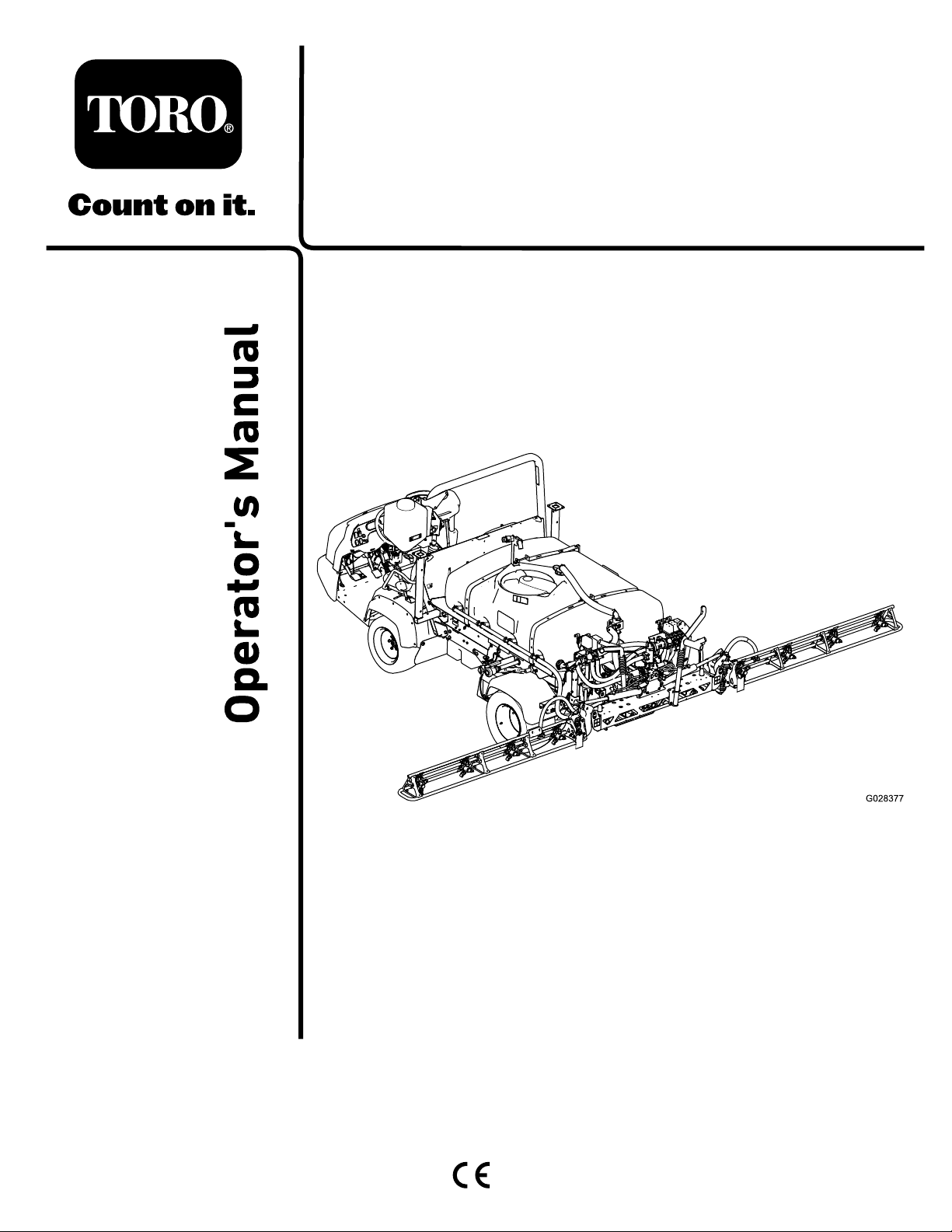
131-5808
decal131-5808
1.Automatic—closed
loop-ratecontrol
2.Manual—openloop-rate
control
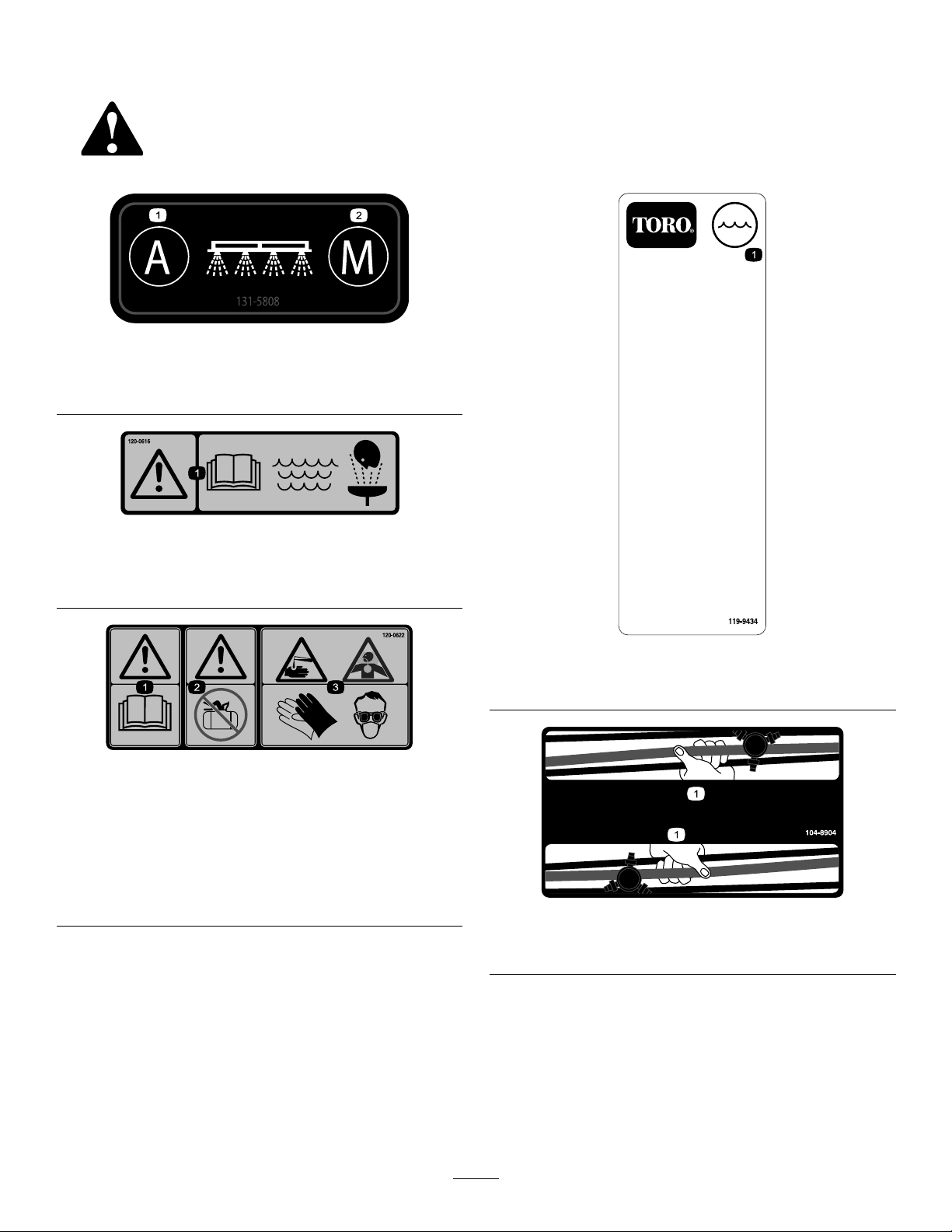
120–0616
1.Warning—readtheOperator’sManual;usefresh,clean
waterforrst-aidwashing.
120–0622
1.Warning—readthe
Operator’sManual.
2.Warning—donotenterthe
sprayertank.
3.Chemicalburnhazard;
toxicgasinhalation
hazard—wearhandand
skinprotection;weareye
andrespiratoryprotection.
decal120-0616
decal119-9434
119-9434
1.Tankcontents
decal120-0622
decal104-8904
104-8904
1.Grasptheboomhere.
9
Page 10
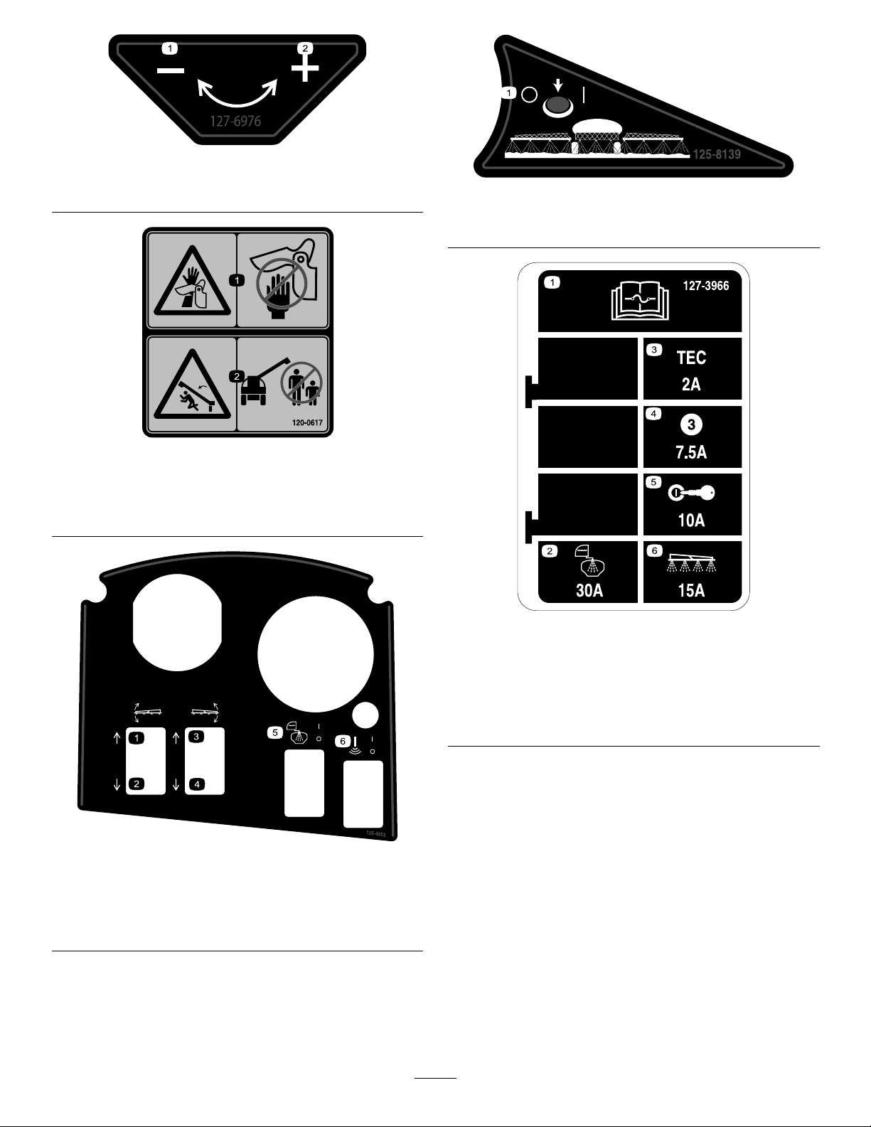
127-6976
1.Decrease2.Increase
120–0617
decal127-6976
decal125-8139
125–8139
1.Toggleboomsprayerson/off
decal120-0617
1.Severinghazardofhand,
pinchingpoint—keep
awayfromactuatedjoints.
2.Crushinghazard—keep
bystandersawayfromthe
machine.
decal125-4052
125–4052
1.Raiseleftboom
2.Lowerleftboom5.Toggletankrinseon/off
3.Raiserightboom
4.Lowerrightboom
6.Togglesonicboomon/off
127–3966
1.ReadtheOperator’s
Manualforinformationon
fuses.
2.30A—Tankrinse5.10A—Ignition
3.2A—TECcontrollerlogic6.15A—Sprayerboom
4.7.5A—TECcontroller
output
decal127-3966
10
Page 11
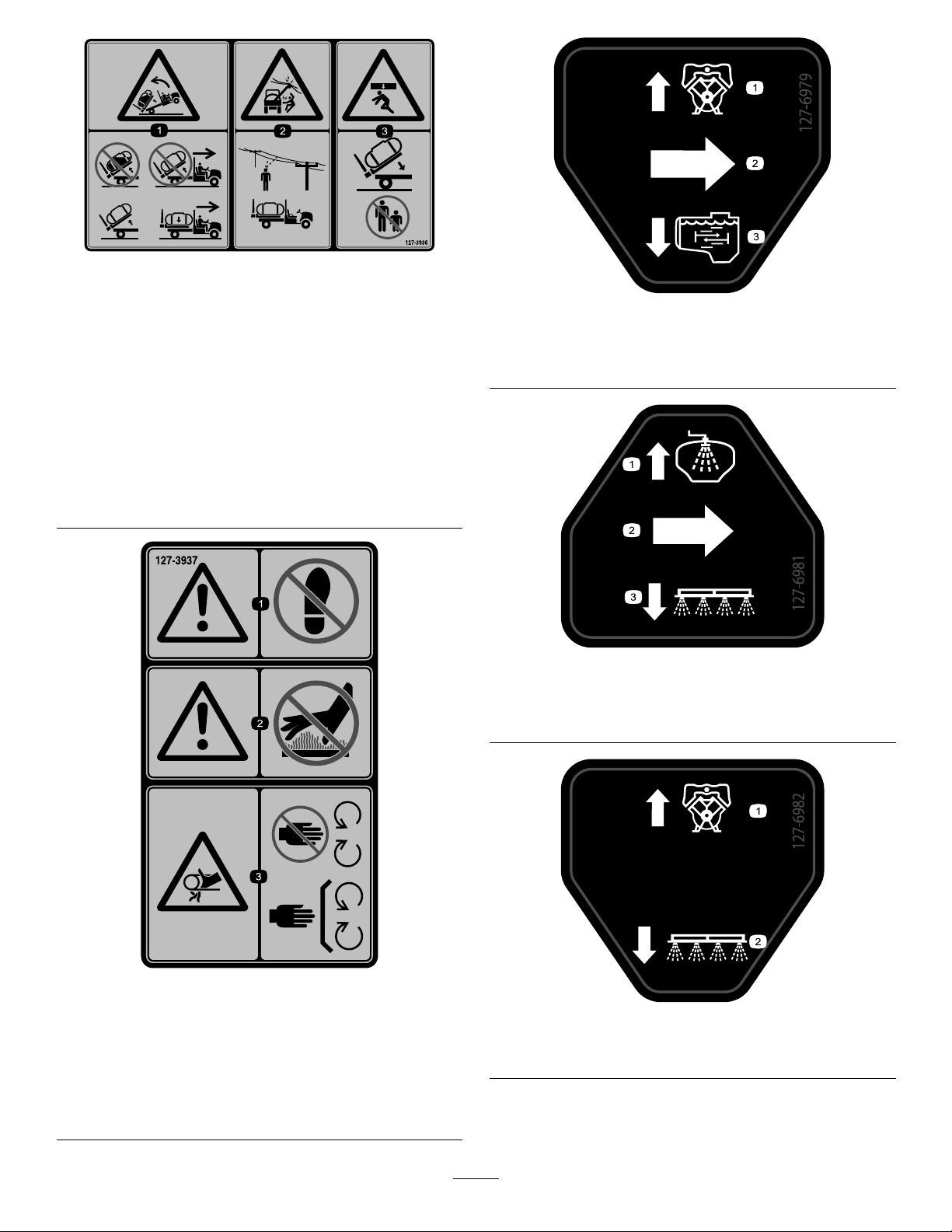
1.Backwardtipping
hazard—donotraise
afulltank;donotmove
themachinewitharaised
tank;onlyraiseand
emptytank;onlymovethe
machinewithalowered
tank.
2.Electricalshockhazard,
overheadpower
lines—checkthearea
foroverheadpowerlines
beforeoperatingthe
machineinthearea.
decal127-3936
127–3936
3.Crushinghazard—keep
bystandersawaywhen
loweringthetank.
127-6979
1.Bypass-returnow3.Agitationow
2.Flow
decal127-6979
decal127-6981
127-6981
127–3937
1.Warning—donotstep.3.Entanglementhazard,
belt—keepawayfrom
movingparts;keepall
guardsandshieldsin
place.
2.Warning—keepawayfrom
hotsurfaces.
1.Bypass-returnow
3.Boomspray
2.Flow
decal127-3937
decal127-6982
127-6982
1.Bypass-returnow
2.Boomspray
11
Page 12

decal127-6984
127-6984
1.Flow
2.Tank-returnow
130-8294
1.Leftboom5.Centerboomsprayon9.Rightboomsprayoff
2.Leftboomsprayon6.Centerboomsprayoff10.Speed
3.Leftboomsprayoff
4.Centerboom
7.Rightboom11.Increasespeed
8.Rightboomsprayon12.Decreasespeed
decal130-8294
13.Agitation
14.Agitationon
15.Agitationoff
12
Page 13

Setup
LooseParts
Usethechartbelowtoverifythatallpartshavebeenshipped.
ProcedureDescription
1
2
3
4
5
Nopartsrequired
RearPTOKit,Heavy-DutyWorkman
Vehicle(HD-SeriesModelswitha
ManualTransmission)
MultiProWMTurfSprayerFinishing
Kit,ManualWorkmanUtilityVehicle
(HD-SeriesModelswithaManual
Transmission)
Hairpin1
Controlconsole
MultiProWMTurfSprayerFinishing
Kit,ManualWorkmanUtilityVehicle
(HD-SeriesModelswithaManual
Transmission)
MultiProWMTurfSprayerFinishing
Kit,AutomaticWorkmanUtilityVehicle
(HDX-AutoModel)
Consolemountingbracket
Flangelocknut(5/16inch)
Flange-headbolt(5/16inch)
Plasticbushing2
Hold-downbrackets2
Tankandskidassembly1
Clevispins
Taperedclevispin2
Hairpins2
Lynchpins4
Bolt(1/2x1-1/2inches)
Nuts(1/2inch)
Qty.
Use
–
1
1
1
1
1
1
3
3
2
2
2
Removetheexistingbed.
Preparetoinstallthecenterboom
section.
Installtheconsolemountingbracket.
Installtheattachmenthold-down
brackets.
Installthetankskid.
6
7
8
9
10
11
Nopartsrequired
Nopartsrequired
Knob1
J-clips3
Bolt(1/4x3/4inch)
Flangenut(1/4inch)
Fusedecal(127–3966)
Batteryterminalbolt1
Clampnut
Cover(batteryterminal—red)
Bolt(1/2x1-1/2inch
Locknut(1/2inch)
13
–
–
1
1
1
2
1
2
2
Connectthespeedsensorharness.
Couplethesprayerpump.
Installthecontrolconsoleontothe
machine.
Installthecontrolconsoleandthe
electricalharness.
Connectthesprayerharnesstothe
battery.
Lowerthetankskid.
Page 14

ProcedureDescription
12
13
14
16
17
Center-boomassembly
Bolt(3/8x1inch)
Flangedlocknut(3/8inch)
Boom-transportcradle2
Bolt(1/2x1-1/4inches)
Flangenut(1/2inch)
Leftboomsection
Rightboomsection1
Flanged-headbolts(3/8x1-1/4inch)
Backingplates8
Flangedlocknuts(3/8inch)
Clevispin
Hairpin2
Hoseclamps3
R-clamp2
Shoulderbolt
Washer2
Nut2
Supporttube(freshwatertank)
Jamnut(3/8inch)
Bolt(3/8x1inch)
Shoulderbolt
Locknut(3/8inch)
Fresh-watertank1
Fresh-watertankmount1
Flangedlocknut(5/16inch)
Washer(5/16inch)
Flanged-headbolt(5/16x2-1/4inch)
Flanged-headbolt(5/16x5/8inch)
Fillreceptacleassembly1
Flange-headbolt(5/16x3/4inch)
Qty.
10
10
Use
1
Installtheboomsection.
4
4
1
8
Installtheleftandrightboomsections.
8
2
2
1
1
1
2
2
2
2
2
4
1
Installtheboomhoses.
Installthefresh-watertank.
Installtheanti-siphonllreceptacle.
18
19
20
Nopartsrequired
Frontjackstand2
Rearjackstand2
Cotterpin
Clevispin(4-1/2inch)
Clevispin(3inch)
Knob2
Operator'sManual
Operatortrainingmaterial
PartsCatalog
Registrationcard1
Selectionguide
Pre-deliveryinspectionsheet1
–
4
2
2
1
1
1
1
Note:Determinetheleftandrightsidesofthemachinefromthenormaloperatingposition.
Checktheboomhingesprings.
Storethejackstands(optional).
Readthemanualsandviewthetraining
materialbeforeoperatingthemachine.
14
Page 15
pinstowardthecenterlineofthemachine(Figure
3).
1
RemovingtheExistingBed
NoPartsRequired
Procedure
CAUTION
Thefullbedweighsapproximately95kg(210
lb),sodonottrytoinstallorremoveitby
yourself.Getthehelpof2or3otherpeople
oruseanoverheadcrane.
1.Ensurethattheparkingbrakeissetandstart
theengineofthemachine.
2.Movethehydraulicliftleverforwardandlower
thebeduntiltheclevispinsforthecylinderrod
endliftcylindersarelooseinthemountingslots
ofthebedmountingplates.
3.Releasethehydraulicliftlever,setthehydraulic
liftlocklever,andshutofftheengine;refertothe
Operator’sManualofyourmachine.
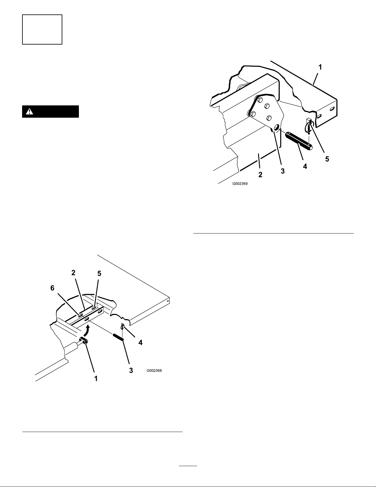
6.Removethelynchpinsandclevispinssecuring
thepivotbracketsofthebedtotheframe
channelsofthemachine(Figure4).
Figure4
1.Leftrearcornerofbed4.Clevispin
2.Vehicleframechannel
3.Pivotplate
5.Lynchpin
g002369
4.Removethelynchpinsfromtheouterendsof
thecylinderrodclevispins(Figure3).
Figure3
1.Cylinderrodend
2.Bedmountingplate
3.Clevispin6.Frontslots(2/3bed)
4.Lynchpin
5.Rearslots(Fullbed)
7.Liftthebedoffthevehicle.
8.Stowtheliftcylindersinstorageclips.
g002368
5.Removetheclevispinssecuringthecylinderrod
endstothebedmountingplatesbypushingthe
15
Page 16
2
PreparingtoInstallthe
TankSkid
Partsneededforthisprocedure:
RearPTOKit,Heavy-DutyWorkmanVehicle
1
(HD-SeriesModelswithaManualTransmission)
MultiProWMTurfSprayerFinishingKit,Manual
1
WorkmanUtilityV ehicle(HD-SeriesModelswitha
ManualTransmission)
1Hairpin
1
Controlconsole
MultiProWMTurfSprayerFinishingKit,Manual
1
WorkmanUtilityV ehicle(HD-SeriesModelswitha
ManualTransmission)
MultiProWMTurfSprayerFinishingKit,Automatic
1
WorkmanUtilityVehicle(HDX-AutoModel)
InstallingtheRearPTOKitfor
HeavyDutyWorkmanVehicles
(HD-SeriesModelswithaManual
Transmission)
ForHD-andHDX-SeriesWorkmanmodelswith
amanualtransmission,fullyinstalltheRearPTO
KitforHeavy-DutyWorkmanVehicles;refertothe
InstallationInstructionsfortheRearPTOKitforHeavy
DutyWorkmanVehicles.
g023738
Figure5
1.Rearliftpoint2.Frontliftpoint
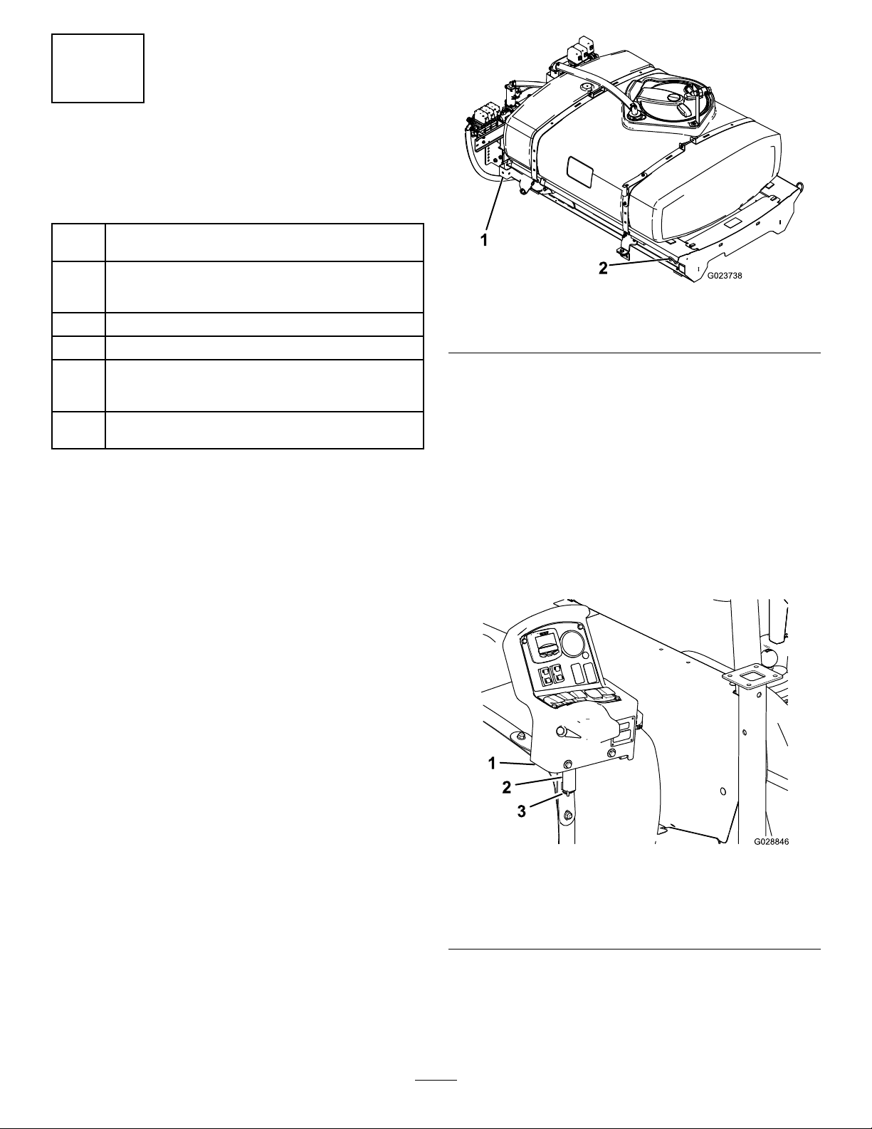
InstallingtheControlConsole
Note:Thissteptemporarilymountsthecontrol
consoletothetankwhileyouassemblethesprayer
tothemachine.Youwillcompletetheinstallationof
thecontrolconsolein9InstallingtheSprayerFuse
Block(page22).
1.Carefullyremovethecontrolconsolefromthe
shippingcontainer
2.Alignthepivotpinonthecontrolconsolewiththe
storagebracketatthefronttankstrap(Figure6).
High-FlowHydraulicsKit,
WorkmanHDX-AutoUtilityVehicle
(Non-TC—HDX-AutoModel)
FullyinstalltheHigh-FlowHydraulicsKitforWorkman
HDX-AutoUtilityVehicles;refertotheInstallation
InstructionsfortheHigh-FlowHydraulicsKit,
WorkmanHDX-AutoUtilityVehicle.
LiftingtheSprayerSkid
Usingliftingequipmentwitha408kg(900lb)lift
capacity,liftthetankskidfromtheshippingcrateat
the2frontand2rearliftpoints(Figure5).
Note:Ensurethatthetankskidisraisedhighenough
toinstallthejackstands.
Figure6
1.Controlconsole
2.Storagebracket(fronttank
strap)
3.Assembletheconsoletothebracketandsecure
thepivotpintothebracketwiththehairpin
(Figure6).
16
3.Hairpin
g028846
Page 17
MultiProWorkmanTurfSprayer
FinishingKit(HD-SeriesModels
withaManualTransmission)
ForHD-andHDX-SeriesWorkmanmodelswith
amanualtransmission,completethestepsinthe
MultiProWMTurfSprayerFinishingKitforManual
WorkmanUtilityVehicles;refertotheInstallation
InstructionsfortheMultiProWMTurfSprayer
FinishingKit,ManualWorkmanUtilityVehicle.
MultiProWorkmanTurfSprayer
FinishingKit(HDX-AutoModel)
HDX-AutomaticSeriesWorkmanmodels,complete
thestepsintheMultiProWMTurfSprayerFinishing
KitforAutomaticWorkmanUtilityVehicles;referto
theInstallationInstructionsfortheMultiProWMTurf
SprayerFinishingKit,AutomaticWorkmanUtility
Vehicle.
Note:Discardtheboltsandnuts.
3
InstallingtheConsole
MountingBracket
Partsneededforthisprocedure:
1
Consolemountingbracket
3
Flangelocknut(5/16inch)
3
Flange-headbolt(5/16inch)
2Plasticbushing
Procedure
Note:OnsomeWorkmanvehicles,thecontrolmount
plateisattachedtothedashboardatthesamelocation
wherethebracketfortheoptionalhandthrottlekit
ismounted.Ifthehandthrottlekitisinstalled,you
willneedtoremovethebracketofthehandthrottle
assemblyfromthedashboard,alignthecontrolmount
platetothedash,andinstallthehandthrottlebracket
ontopofthecontrolmountplate.RefertotheHand
ThrottleKitInstallationInstructionsfordirectionson
removingandinstallingthehandthrottleassembly .
Figure7
1.Bolt
2.Nut
3.Cashpanel(lowercenter
area)
4.Mountingbracket(control
console)
2.Aligntheholesinthemountingbracketforthe
controlconsolewiththeholesinthedashand
supportbracket(Figure7).
3.Assemblethemountingbracketdashpaneland
supportbracketwiththe3anged-headbolts
(5/16x1inch)and3angedlocknuts(5/16inch)
4.Torquethenutsandboltsto(Figure7).
5.Insertthe2plasticbushingsintothemounting
bracket(Figure7).
5.Bushing(plastic)
6.Flanged-headbolts(5/16
x1inch)
7.Flangedlocknuts(5/16
inch)
g028408
1.Removethe3boltsand3nutsthatsecurethe
lower-centerportionofthedashpaneltothe
dashsupportbracket(Figure7).
Note:SomeolderWorkmanmachinesmayuse
4boltsandangenuts.
17
Page 18
4
InstallingtheHold-down
BracketsfortheTankSkid
Partsneededforthisprocedure:
2Hold-downbrackets
Procedure
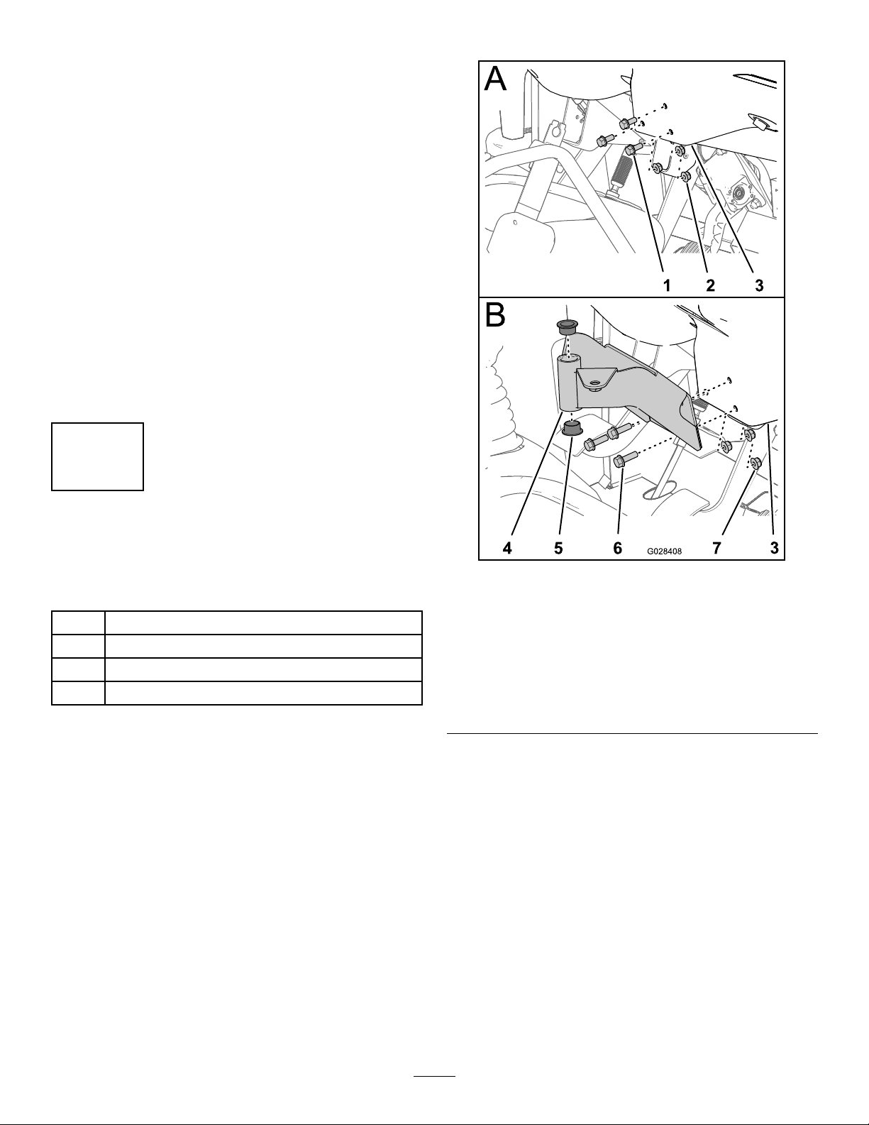
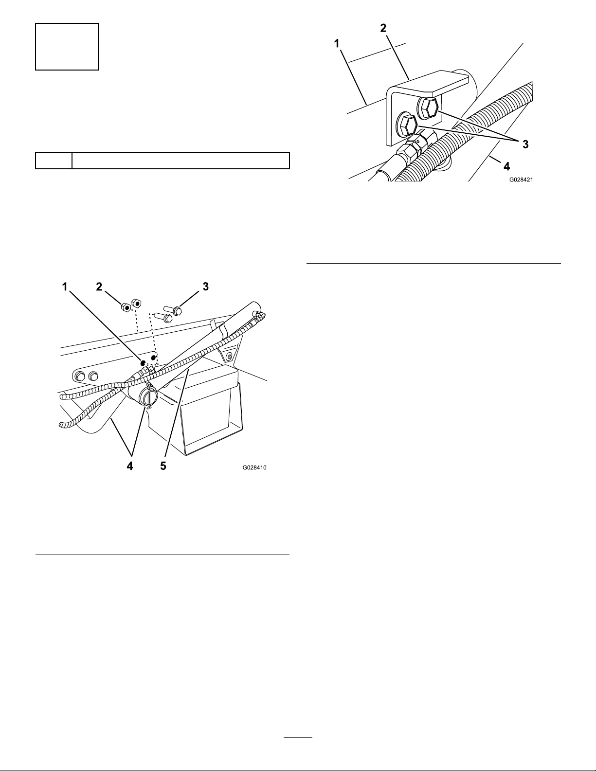
1.Removethe2rearanged-headboltsand2
angedlocknutsthatsecurethesupportbracket
fortheenginetubetotheframeofthemachine
(Figure8).
1.Supportbracket(engine
tube)
2.Hold-downbracket(tank
skid)
g028421
Figure9
3.Flanged-headbolts
4.Liftcylinder
Note:Retainthefastenersforlateruse.
Figure8
1.Rearhole—support
bracket(enginetube)
2.Flangedlocknut
3.Flanged-headbolt
4.Torquetheboltsandnutsto91to113N-m(67
to83ft-lb).
5.Repeatsteps1to4attheoppositesideofthe
machine.
g028410
4.Enginesupporttube
5.Liftcylinder
2.Rotatetheliftcylindertoprovideclearanceto
installthehold-downbracketforthetankskid
(Figure8).
3.Assemblethehold-downbracketstosupport
bracketandframetheusingthe2anged-head
boltandangelocknutremovedinstep1(Figure
9).
18
Page 19
5
InstallingtheTankSkid
Partsneededforthisprocedure:
1Tankandskidassembly
2
Clevispins
2Taperedclevispin
2Hairpins
4Lynchpins
2
Bolt(1/2x1-1/2inches)
2
Nuts(1/2inch)
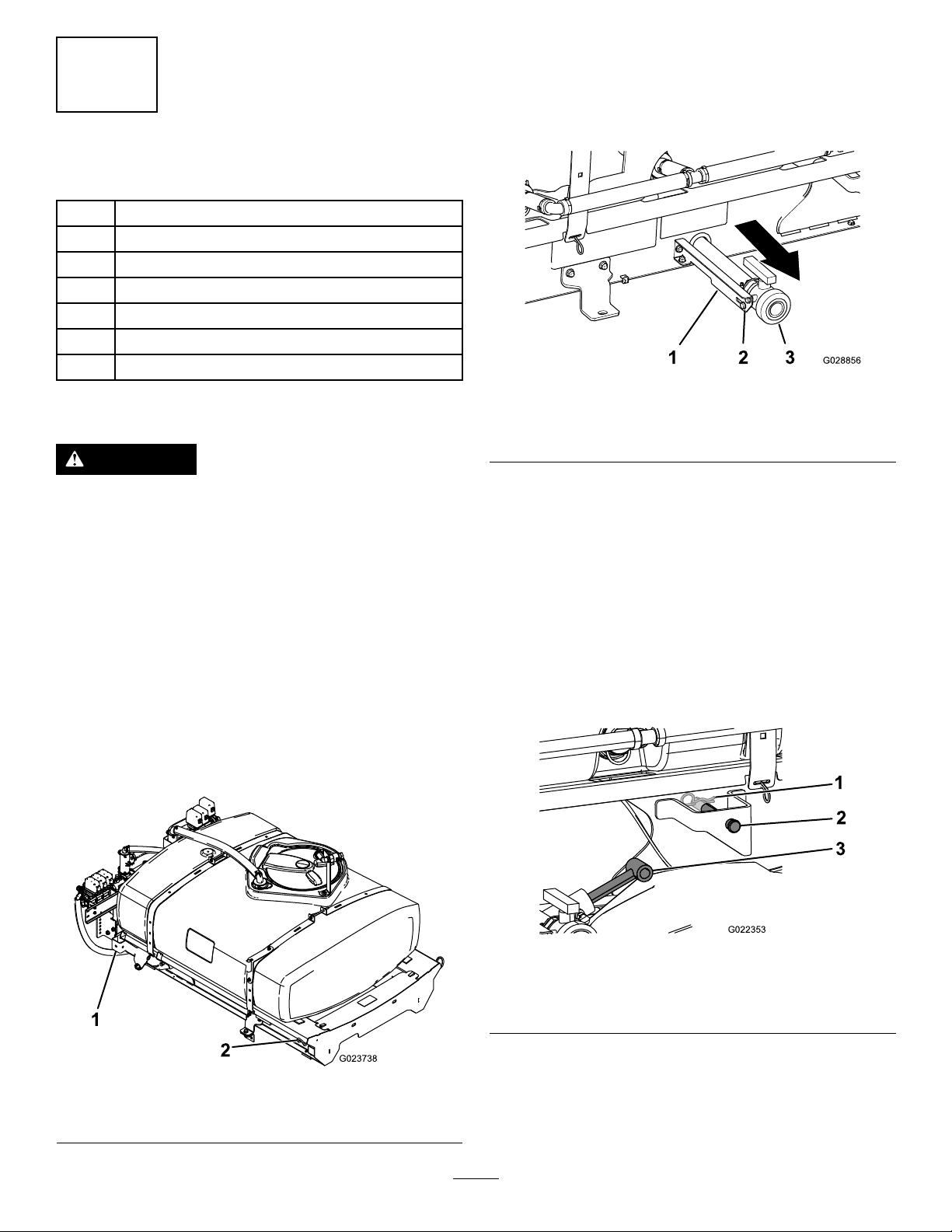
2.Positionthedrainvalveasfollows:
A.Attheleftsideofthetank,loosenthe2
anged-headboltsthatsecurethedrain
valvetothevalve-supportbracket(Figure
11).
g028856
Figure11
Procedure
DANGER
Thesprayertankassemblyrepresentsa
storedenergyhazard.Ifnotproperlyretained
wheninstallingorremovingtheassembly,
itcanmoveorfallandinjureyouorother
bystanders.
Usestrapsandanoverheadlifttosupport
thesprayertankassemblyduringinstallation,
removal,oranymaintenancewhenthe
retainingfastenersarebeingremoved.
1.Usingalift,raisethetankskidassembly(Figure
10)andpositionitoverthevehicleframewith
thepumpandvalveassembliesfacingrearward.
Note:Haveanotherpersonhelpyouperform
thefollowingsteps.
1.Valve-supportbracket3.Drainvalve
2.Flanged-headbolt
B.Movethedrainvalvefullyoutwardinthe
slotsofthebracket(Figure11).
Note:Ensurethatthedrainhoseatthe
inboardsideofthesprayerskidisnot
kinked.
C.Tighten2angedheadbolts(Figure11).
3.Slowlylowerthetankskidontotheframeofthe
machine.
4.Extendtheliftcylinderstothebracketsonthe
tankskid,andalignthecylinderttingswiththe
holesinthetankskidbrackets(Figure12).
Figure10
1.Rearliftpoint2.Frontliftpoint
g022353
Figure12
1.Hairpin
2.Clevispin
g023738
5.Securethetankskidtotheliftcylinderswith
theclevispinsandhairpinsatbothsidesofthe
machine.
6.Lineuptheholesinthepivotlugsattherear
ofthetankskidassemblywiththeholesinthe
19
3.Liftcylinders
Page 20
bedpivottubeattheendofthevehicleframe
(Figure13).
Figure13
1.Taperedclevispin2.Lynchpin
7.Installataperedclevispinand2lynchpinsto
thepivotlugtosecurethetankassemblytothe
frame(Figure13).
8.Extendtheliftcylinderstoraisethetankand
supportitsweight.
Note:Disconnectthetankassemblyfromthe
liftingequipment.
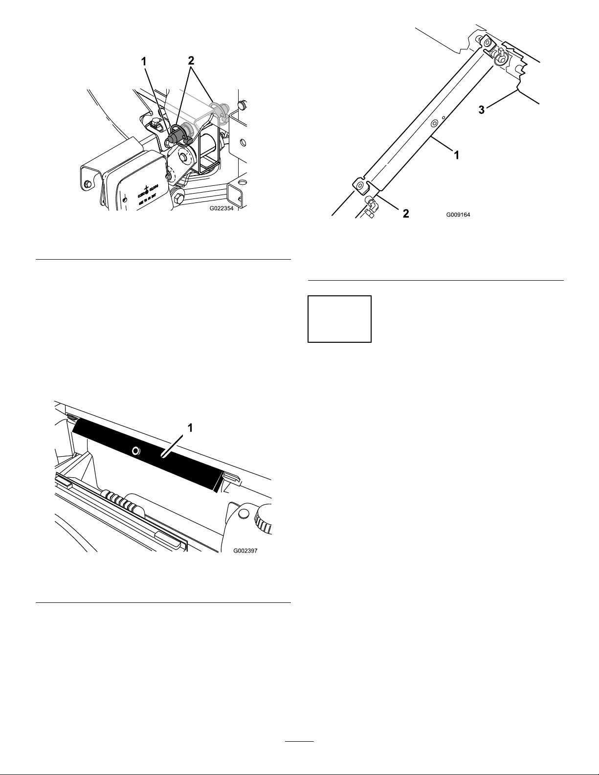
9.Removethebedsupportfromthestorage
bracketsonbackoftheROPSpanel(Figure14).
g022354
Figure15
1.Bedsupport
2.Liftcylinder
3.Skidframe
g009164
6
ConnectingtheSpeed
SensorHarness
NoPartsRequired
ConnectingtheSpeedSensor
Harness(HD-SeriesModelswitha
ManualTransmission)
Figure14
1.Bedsupport
10.Pushthebedsupportontothecylinderrod,
makingsurethatthesupportendtabsreston
theendofcylinderbarrelandonthecylinderrod
end(Figure15).
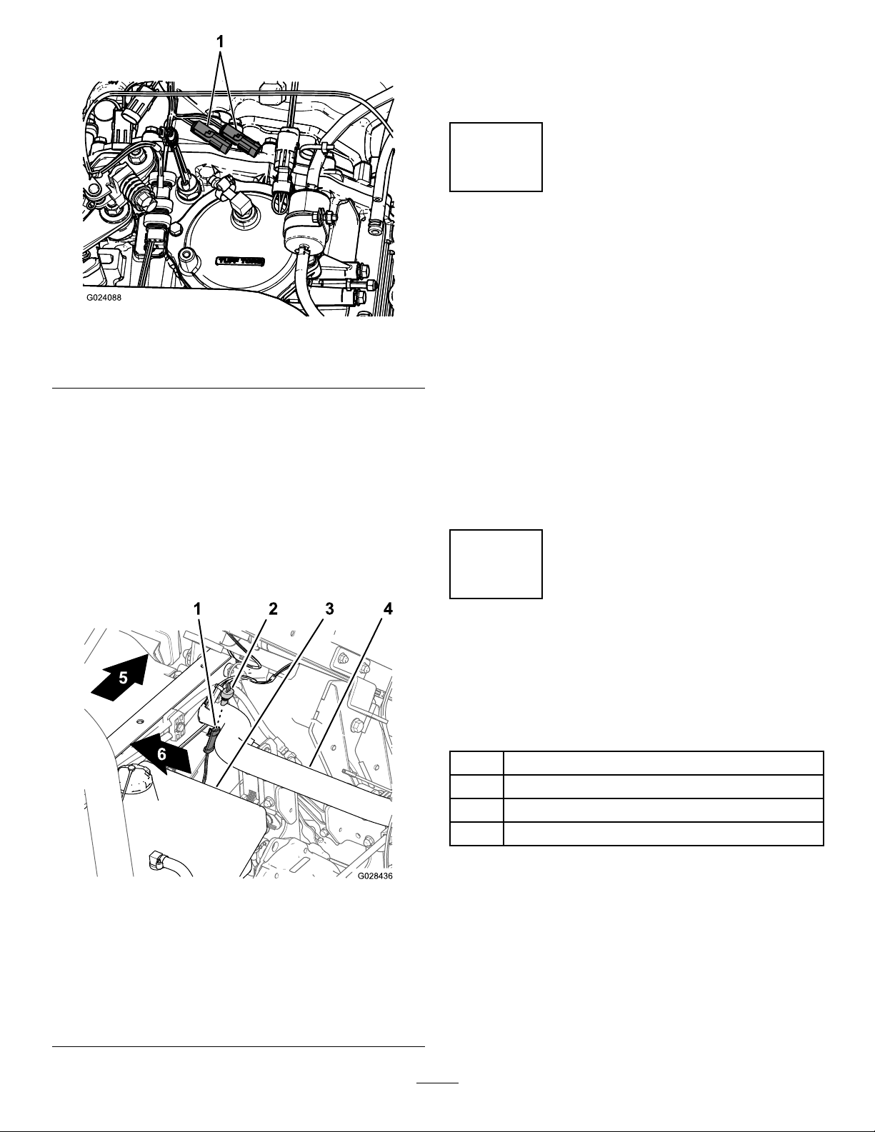
1.Atthewiringharnessforthesprayer,locatethe
3-socketconnectorforthespeedsensorcircuit
andthe3-pinconnectorforthevehiclecircuit.
2.Atthetransaxleofthemachine,connectthe
g002397
20
3-pinconnectorofthewiringharnessofthe
machineforspeedsensorintothe3-socket
connectorofthesprayerharnessforthespeed
sensor(Figure16).
Page 21
2.Connectthe3-pinconnectorofthewiring
harnessofthemachineforspeedsensorinto
the3-socketconnectorofthesprayerharness
forthespeedsensor(Figure17).
7
CouplingtheSprayerPump
NoPartsRequired
Figure16
1.Existingspeedsensorplugs
3.Connectthe3-pinconnectorforthevehicle
circuitofthewiringharnessofthesprayerinto
the3-pinsocketforthevehiclecircuitofthe
wiringharnessforthemachine.
ConnectingtheSpeedSensor
Harness(HDX-AutoModel)
1.Atthewiringharnessforthesprayer,locatethe
3-socketconnectorforthespeedsensorcircuit
(Figure17).
g024088
Procedure
•ForHD-seriesmodelswithamanualtransmission,
couplethePTOshafttothetransaxlePTO;refer
totheInstallationInstructionsfortheMultiProWM
TurfSprayerFinishingKit,ManualWorkmanUtility
Vehicle.
•ForHDX-Automodel—connectthehydraulic
motorhosestothequick-disconnectttingsatthe
high-owhydraulicpanel;refertotheInstallation
InstructionsfortheMultiProWMTurfSprayer
FinishingKit,AutomaticWorkmanUtilityVehicle.
8
InstallingtheControl
ConsoleandElectrical
Harness
1.3-pinconnector(machine
wiringharness—speed
sensor)
2.3-socketconnector
(sprayerwiring
harness—speedsensor)
3.Hydrauliictank
Figure17
4.Rear-frametube
5.Backofthemachine
6.Rightsideofthemachine
Partsneededforthisprocedure:
1Knob
3J-clips
1
Bolt(1/4x3/4inch)
1
Flangenut(1/4inch)
g028436
InstallingtheControlConsoleto
theMachine
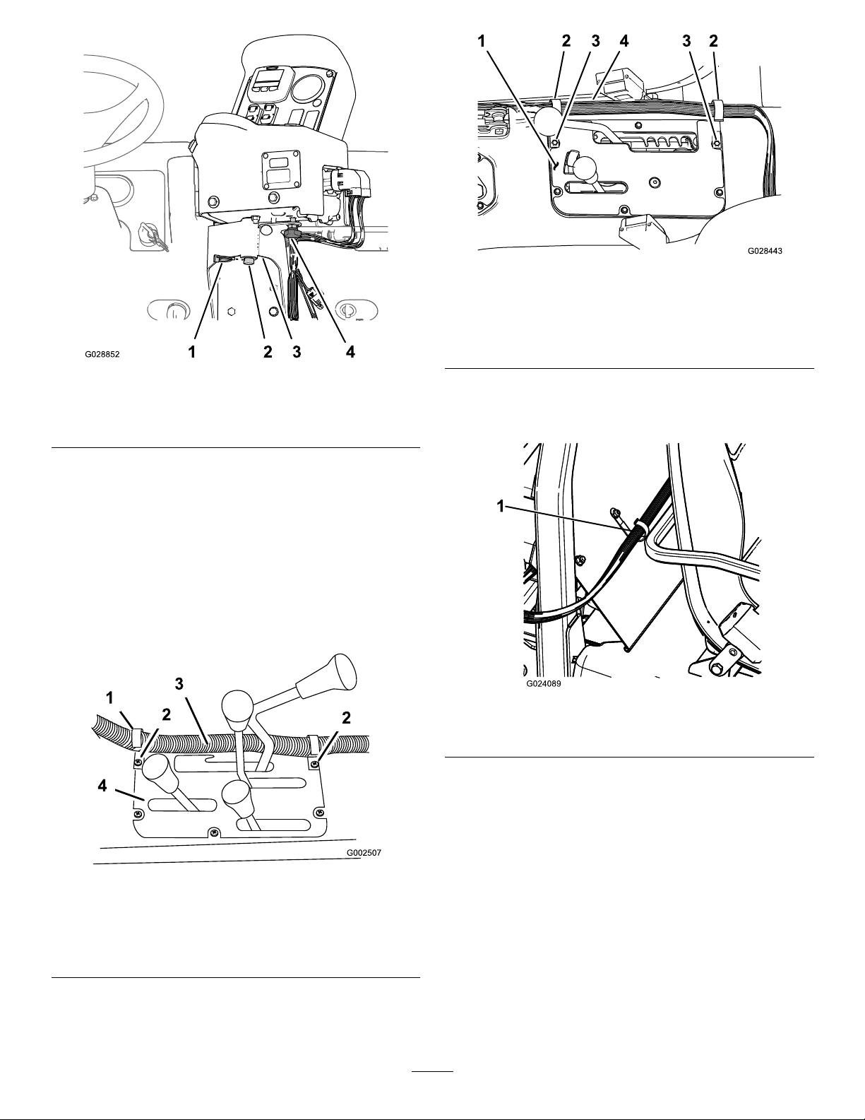
1.Removethehairpinsecuringthepivotpinofthe
controlconsoletothestoragebracketonthe
sprayertank.
2.Installthecontrolconsoleontothecontrol
mountingbracketandsecurethecontrolconsole
withthepreviouslyremovedhairpin(Figure18).
21
Page 22
HDX-AutoModel
g028443
Figure20
Figure18
1.Hairpin
2.Pivotpin(controlconsole)
3.Controlmountingbracket
4.Handknob
3.Installthehandknobandtightenittopreventthe
consolefromrotatingduringoperation(Figure
18).
InstallingtheControlConsole
ElectricalHarnesstotheMachine
1.Install2J-clipsinthecenterconsoleatthe
pointslocatedinFigure19orFigure20using
theexistingscrews.
1.Centerconsole
2.J-clip
g028852
3.Existingscrews
4.Control-boxharness
2.InstallaJ-clipbehindthepassengerseatusing
abolt(1/4x1/2inch)andaangednut(1/4
inch)(Figure21).
g024089
Figure21
1.J-clip
HD-Seriesmodelswithanmanualtransmission
1.J-clip
2.Existingscrews
3.Securethecontrolconsoleharnesstothe
consoleandROPScoverusingtheJ-clips
(Figure21).
g002507
Figure19
3.Control-boxharness
4.Centerconsole
22
Page 23
9
InstallingtheSprayerFuse
Block
Partsneededforthisprocedure:
1
Fusedecal(127–3966)
Procedure
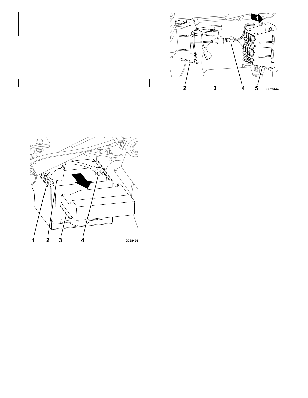
1.Squeezethesidesofthebatterycovertorelease
thetabsfromtheslotsinthebatterybase,and
removethebatterycoverfromthebatterybase
(Figure22).
Figure23
1.Backofthemachine
2.Fuseblock(sprayer
wiring)
3.Insulatedblade
terminal(yellow,
optional-power
wire—machinefuseblock)
5.Connecttheuninsulatedreceptacleterminalof
thefuseblockforthemachinetotheinsulated
bladeterminalofthefuseblockofthesprayer
(Figure23).
4.Uninsulatedreceptacle
terminal(yellowpower
wire—sprayerfuseblock)
5.Fuseblock(machine
wiring)
g028444
Figure22
1.Slot(batterybase)3.T ab(batterycover)
2.Cover(negativebattery
terminal)
2.Slidethecoverbackandremovethenegative
batteryterminalfromthebattery(Figure22).
3.Removethepositivebatteryterminalfromthe
battery(Figure22).
4.Locatetheuninsulatedreceptacleterminalatthe
endoftheopen,yellowpowerwireofthefuse
blockforthemachineandtheinsulatedblade
terminalattheendoftheyellow,optional-power
wireofthefuseblockofthesprayerwiring
(Figure23).
4.Terminal(positivebattery
cable)
6.AligntheT-ttingsontheofthefuseblockof
thesprayertotheT-slotsofthefuseblockfor
themachineandslidethesprayerfuseblock
intotheslotsuntilthefuseblockisfullyseated
(Figure24).
g028456
23
Page 24
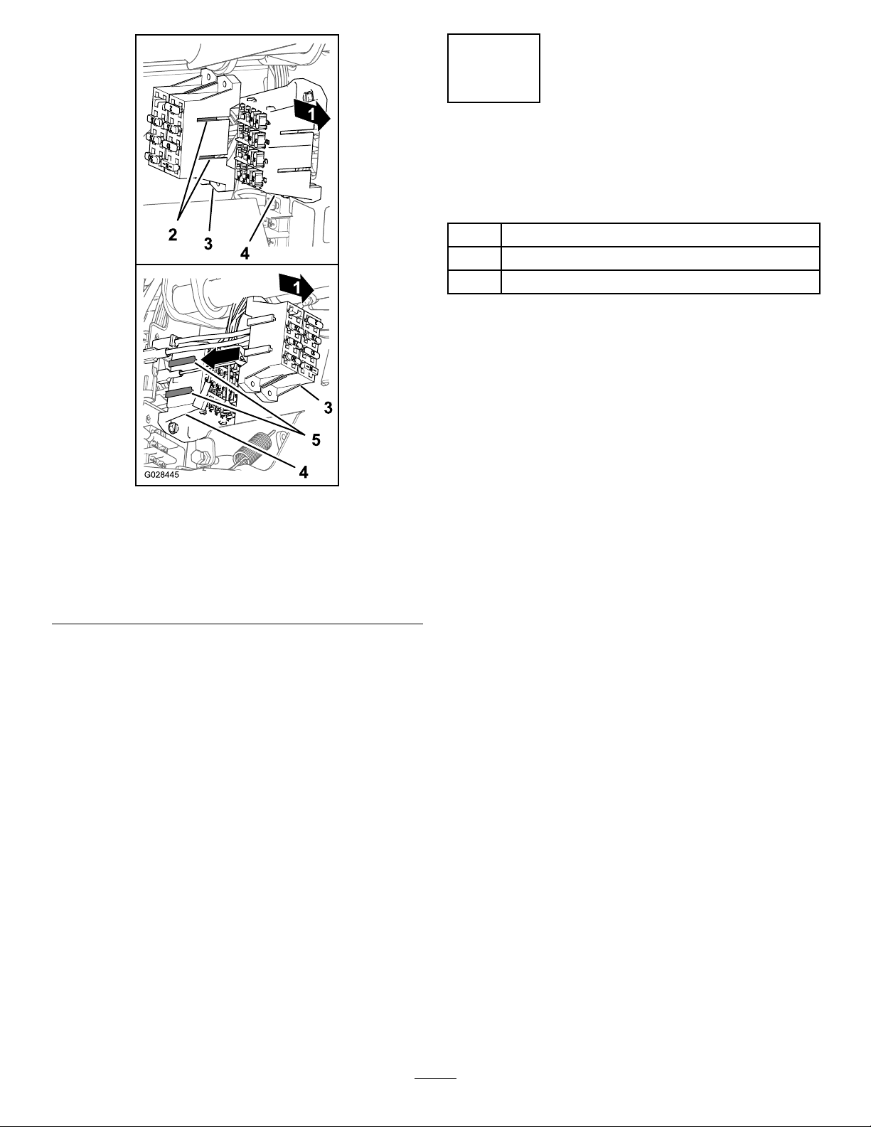
Figure24
10
ConnectingtheSprayer
HarnesstotheBattery
Partsneededforthisprocedure:
1Batteryterminalbolt
2
Clampnut
1
Cover(batteryterminal—red)
Procedure
1.RemovetheexistingnutandT-boltandfromthe
positivebatteryterminal(AofFigure25).
Note:DiscardtheT-boltannut.
g028445
1.Backofthemachine4.T-slots(fuseblockforthe
2.T-ttings(fuseblockfor
thesprayer)
3.Fuseblockforthesprayer
7.Attachthefusedecalonasurfacenearbythe
fuseblockforthesprayer.
machine)
5.Fuseblockofthemachine
24
Page 25

Figure25
1.Terminal(positivebattery
cable)
2.Nut6.T erminalbolt
3.Positivebatterypost
4.T-bolt
2.Sliptheredbatteryterminalcoveroverthe
positivebatterycable(BofFigure25).
5.Cover(battery
terminal—red)
7.Clampnut
tightentheclampnutto1978to2542N-cm(175
to225in-lb).
7.Slidethecoverovertheforthepositivebattery
terminals.
8.Squeezethesidesofthebatterycoverand
inserttabsintotheslotsinthebatterybase.
11
LoweringtheTankSkid
Partsneededforthisprocedure:
2
Bolt(1/2x1-1/2inch
2
Locknut(1/2inch)
Procedure
1.Startthemachineandraisethetankskidslightly
withtheliftcylinders.
2.Removethecylinderlockfromtheliftcylinder
andstowthelockinthestoragebracketsatthe
backoftheROPSpanel(Figure14andFigure
15)
g028457
3.Useliftcylinderstoslowlylowerthetanktothe
frame.
Note:Haveanotherpersonobservethetank
skidasitlowers.Lookforhosesandwiringthat
mightbecomepinchedorbent.
4.Checkthealignmentofthetankskidtothe
frameofthemachine.
5.Removetheaccesspanelsatbothsidesofthe
skidframe.(Figure26).
3.Assemblethenewbatteryterminalboltand
1clampnutontotheterminalofthepositive
batterycable(CofFigure25).
4.Installtheterminalofthebatteryleadfromthe
sprayerwiringharnessontothebatteryterminal
boltandsecuretheterminalwith1clampnut
(DofFigure25).
Note:Alignthebatteryleadalongpositive
batterycable.Tightentheclampnutandboltto
1978to2542N-cm(175to225in-lb).
5.Connectthepositivebatteryterminaltothe
positivebatterypostandtightentheclampnut
to1978to2542N-cm(175to225in-lb).
6.Connectthenegativebatteryterminaltothe
negativebatterypost(EofFigure25)and
Figure26
1.Accesspaneldoor
2.Bolt(1/2x1-1/2inch
6.Checkthehosesorwiringthatyoucansee
throughtheopeningintheskidframeforsigns
ofpinchingorbending.
25
3.Locknut(1/2inch)
g022355
Page 26
Important:Ifanyhosesorwiringonthe
tankskidassemblyarepinchedorbent,
raisetheassemblyup,adjustitspositioning,
andtietheitemsback.
7.Alignthefrontmountingbracketswiththe
hold-downbracketsinstalledin4Installingthe
Hold-downBracketsfortheT ankSkid(page17).
8.Securetheholddownbracketofthetankskid
assemblytothebedbracketontheframeat
eachsideofthemachinewithabolt(1/2x1-1/2
inches)andalocknut(1/2inch)asshownin
Figure26.
9.Torquetheboltandlocknutto91to113N-m(67
to83ft-lb)
10.Repeatsteps7through9attheothersideofthe
tankskidandmachine.
g028458
Figure27
12
InstallingtheCenterBoom
Section
Partsneededforthisprocedure:
1
Center-boomassembly
10
Bolt(3/8x1inch)
10
Flangedlocknut(3/8inch)
2Boom-transportcradle
4
Bolt(1/2x1-1/4inches)
4
Flangenut(1/2inch)
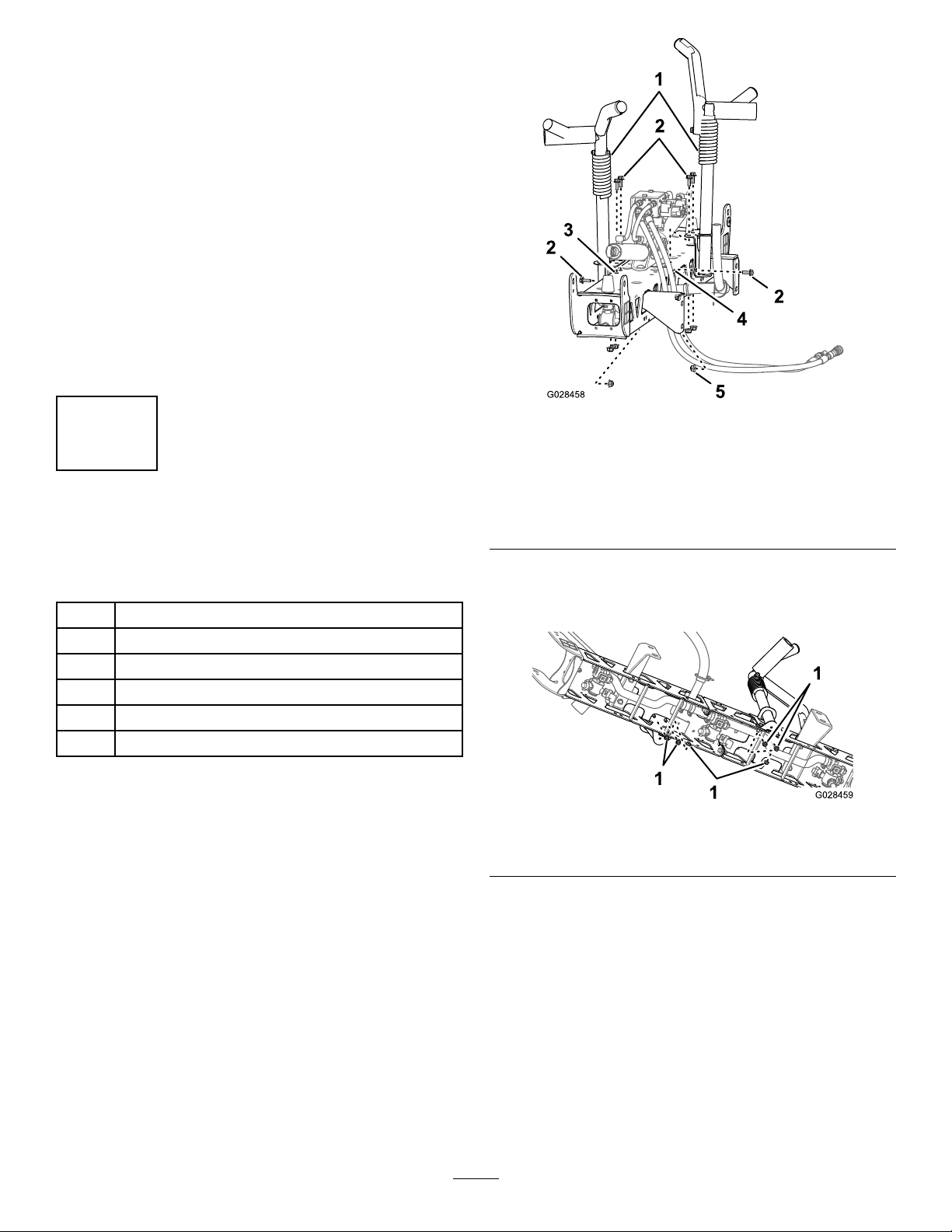
AssemblingtheBoomTransport
Cradles
1.Attachliftingequipmenttothecenterboom
sectionandremoveitfromtheshipping
container.
2.Aligntheboomtransportcradlestothecenter
boomsection(Figure27).
1.Boom-transportcradle
2.Bolts(3/8x1inch)5.Flangedlocknut(3/8inch)
3.Verticalholes(boom
centersection)
3.Assemblethecradlestotheboomsection
(Figure27andFigure28)with6bolts(3/8x1
inch)and6angedlocknuts(3/8inch).
1.Locknuts(3/8inch)
4.Torquetheboltsandnutsto37to45N-m(27
to33ft-lb).
4.Horizontalhole(boom
centersection)
Figure28
g028459
InstallingtheCenterBoomSection
totheTankSkid
1.Startthemachine,removethebedsupportfrom
theliftcylinderandstowthesupport,lowerthe
tankskid,shutoffthemachine,andremovethe
keyfromtheSTARTERswitch.
2.Alignthebottomholeinthesectionmounting
bracketsofthecenterboomassemblywiththe
26
Page 27

thirdholefromthebottomintheboomsupports
onthesprayskidframe,asshowninFigure29.
Note:Ifnecessary,loosentheboomsupports
andadjustedthemtothecenterboomsection
forbetterholealignment.T orquetheboltsand
nutsto67to83N-m(91to113ft-lb).
Figure29
1.Locknut(1/2inch)4.Sectionmountingbracket
2.Hole3—fromthebottom
(boomsupport)
3.Sectionmountingbracket
(left)
3.Assemblethecenterboomassemblytothe
sprayskidframewith4bolts(1/2x1-1/4inches)
and4locknuts(1/2inch).
(right)
5.Bolt(1/2x1-1/4inches)
13
InstallingtheLeftandRight
BoomSection
Partsneededforthisprocedure:
1
Leftboomsection
1Rightboomsection
8
Flanged-headbolts(3/8x1-1/4inch)
8Backingplates
8
Flangedlocknuts(3/8inch)
2
Clevispin
2Hairpin
g028460
Procedure
Eachboomsectionweighsapproximately30lb.
1.Removethe4anged-headbolts(3/8x
1-1/4inch),4backingplates,and4anged
locknuts(3/8inch)fromthehingebracketofthe
center-boomsection.
2.Rotateeachpivotbracketattheendofthe
centerboomsectionsothatthebracketsalign
vertically(Figure30).
4.Torquetheboltsandnutsto67to83N-m(91
to113ft-lb).
ConnectingtheHosesandWiring
fortheBoomLiftValve
•ForHD-SeriesModelswithaManualTransmission,
refertotheinstallationinstructionsfortheMultiPro
WMTurfSprayerFinishingKit,ManualWorkman
UtilityVehicle.
•ForHDX-AutoModel,refertotheinstallation
instructionsfortheMultiProWMTurfSprayer
FinishingKit,AutomaticWorkmanUtilityVehicle.
Figure30
1.Center-boomsection
2.Boomextension6.Backingplates
3.Hingeplate
4.Flanged-headbolts(3/8x
1-1/4inch)
3.Lifttheouter-boomsectionandalignholesin
thetriangularmountingplateattheendofthe
outer-boomsectionwiththeholesinthepivot
bracket.
5.Triangularmountingplate
7.Flangedlocknuts(3/8
inch)
g028737
27
Page 28

Note:Ensurethattheturretsforthesprayer
nozzlesarefacingrearward.
4.Assemblehingeplatetothetriangularplate
using4anged-headbolts,4backingplates,
and4angedlocknuts,thatyouremovedinstep
1,asshowninFigure30.
5.Torquethenutsboltsandnutsto37to45N-m
(27to33ft-lb).
6.Aligntherodendoftheboomliftcylinderwith
theholesinthehornofthepivotbracket(Figure
30).
Figure31
1.Rodend(boomlift
cylinder))
2.Horn(pivotbracket)
3.Clevispin(5/8x4-3/4
inch)
4.Hairpin
7.Securetherodendtothepivotbracketwitha
clevispinandahairpin(Figure30).
8.Repeatstep1through5ontheothersideofthe
center-boomassemblywiththeopposingboom
section.
Note:Beforeyounishthisprocedure,ensure
thatallofturretsforthespraynozzlesarefacing
rearward.
g028738
28
Page 29

14
InstallingtheBoomHoses
Partsneededforthisprocedure:
3Hoseclamps
2R-clamp
2
Shoulderbolt
2Washer
2Nut
InstallingtheLeftandRightBoom
SectionHoses
1.Routetheboom-sectionhosesasshownin
Figure32andFigure33.
1.Nut
2.Washer
3.R-clamp6.Hoseclamp
4.Shoulderbolt7.Left-boomhose
5.T-tting8.Left-sectionvalve
g028468
Figure32
Hose—LeftBoomSegment
29
Page 30

Hose—RightBoomSegment
g028469
Figure33
1.Nut
2.Washer
3.R-clamp6.Hoseclamp
4.Shoulderbolt
5.T-tting
2.Securetheboomhosestothefrontsideofthe
centerboomsection(Figure32andFigure33)
with1R-clamp,1shoulderedbolt(5/16x1inch),
1locknut(5/16inch)and1washer(5/16inch).
3.Installtheboomsectionhoseoverthebarbed
T-ttingattheboomsectionandsecurethehose
withahoseclamp(Figure32andFigure33).
Note:Applyacoatofliquidsoaptothehose
barboftheteettingtoeaseinstallationofthe
hose.
4.Repeatsteps1through3onthehosetothe
boomsectionontheothersideofthesprayer.
7.Right-boomhose
8.Right-sectionvalve
InstallingtheCenterBoom-Section
Hose
1.Routethecenterboom-sectionhoseasshown
inFigure34.
Figure34
1.Up
2.T-tting5.Center-sectionvalve
3.Hoseclamp
4.Center-boomhose
6.Frontofthemachine
g028471
30
Page 31

2.Installtheboomsectionhoseoverthebarbed
T-ttingatthecenterboomsectionandsecure
thehosewithahoseclamp(Figure34).
Note:Applyacoatofliquidsoaptothehose
barboftheteettingtoeaseinstallationofthe
hose.
15
InstallingtheNozzles
NoPartsRequired
Procedure
Thenozzlesthatyouusetoapplyyourchemicals
varydependingontherateofapplicationthatyou
need;therefore,nozzlesarenotsuppliedwiththekit.
Toobtainthecorrectnozzlesforyourneeds,contact
yourAuthorizedT oroDistributorandbepreparedto
givethemthenfollowinginformation:
16
InstallingtheFresh-Water
Tank
Partsneededforthisprocedure:
1
Supporttube(freshwatertank)
1
Jamnut(3/8inch)
1
Bolt(3/8x1inch)
2
Shoulderbolt
2
Locknut(3/8inch)
1Fresh-watertank
1Fresh-watertankmount
2
Flangedlocknut(5/16inch)
2
Washer(5/16inch)
2
Flanged-headbolt(5/16x2-1/4inch)
4
Flanged-headbolt(5/16x5/8inch)
•Thetargetapplicationrateinlitersperhectare,US
gallonsperacre,orUSgallonsper1000sqft.
•Thetargetspeedofthevehicleinkilometersper
hourormilesperhour.
Toinstallanozzle,completethefollowing:
1.Threadorinsertthenozzleintothenozzle
receptaclefollowedbyagasket.
2.Slidethenozzlereceptacleoverthenozzle
ttingonaturret.
3.Turnthenozzleclockwisetolockthecamson
thereceptacleinplace.
4.Verifythefanportionofthenozzle.
SeetheInstallationInstructionsaccompanyingthe
nozzlesformoreinformation.
InstallingtheTankSupportTube
1.Alignthesupporttubeforthefreshwatertank
withthetanksupportchannel(Figure35).
Figure35
1.Supporttube(freshwater
tank)
2.Jamnut(3/8inch)6.Locknut(3/8inch)
3.Frontofthemachine7.Weldnut(tanksupport
4.Up
5.Bolt(3/8x1inch)
channel-freshwater
8.Shoulderbolt
g028872
2.Aligntheholesinthesupporttubewiththeholes
inthechannel(Figure35).
3.Securethetubetothechannel(Figure35)with
the2shoulderboltsand2locknuts(3/8inch).
31
Page 32

4.Threadthejamnut(3/8inch)intothebolt(3/8x
1inch);refertoFigure35.
5.Threadtheboltandjamnutintotheweldnut
atthebottomofthetanksupportchanneland
tightentheboltandjamnut(Figure35).
InstallingtheTank
Note:Thefresh-watertankcannotbeinstalledona
2postROPS.
1.Aligntheholesinthemountforthefresh-water
tankwiththeholesinthesupporttube(Figure
36).
g028474
Figure37
Figure36
1.Supporttube4.Washer(5/16inch)
2.Flangedlocknut(5/16
inch)
3.Mount(fresh-watertank)
5.Flanged-headbolt(5/16x
2-1/4inch)
2.Securethemounttothetube(Figure36)with2
anged-headbolts(5/16x2-1/4inch),2washers
(5/16inch),and2angedlocknuts(5/16inch).
3.Torquetheboltsandnutsto1978to2542N-cm
(175to225in-lb).
4.Applymedium-gradethread-lockingcompound
tothe4anged-headbolt(5/16x5/8inch).
1.Flanged-headbolt(5/16x
5/8inch)
2.Hole(fresh-watertank
mount)
3.Threadedinsert
(fresh-watertank)
6.Securethefresh-watertanktothemount(Figure
37)with4anged-headbolt(5/16x5/8inch).
7.Torquetheboltsandnutsto1978to2542N-cm
(175to225in-lb).
g028473
5.Alignthethreadedinsertsinthefreshwatertank
withtheholesinthefresh-watertankmount
(Figure37).
32
Page 33

17
18
InstallingtheAnti-siphon
FillReceptacle
Partsneededforthisprocedure:
1Fillreceptacleassembly
1
Flange-headbolt(5/16x3/4inch)
Procedure
Placethell-receptacleassemblyoverthethreaded
holeinthetankandsecureitwithaange-headbolt
(5/16x3/4inch)(Figure38).
CheckingtheBoomHinge
Springs
NoPartsRequired
Procedure
Important:Operatingthespraysystemwith
theboomhingespringsundertheincorrect
compressioncoulddamagetheboomassembly.
Measurethespringsandusethejamnutto
compressthespringsto4cm(1–1/2inches)if
necessary.
Thesprayerisshippedwiththeboomextensions
swungforwardtofacilitatepackagingofthemachine.
Thespringsarenotfullytightenedatthetimeof
manufacturetoallowtheboomstobeinthisposition
fortransit.Beforeoperatingthemachine,adjustthe
springstothecorrectcompression.
1.Ifnecessary,removethepackingcomponents
thatsecuretherightandleftextensionbooms
duringshipping.
Figure38
1.Fill-receptacleassembly2.Flangebolt
(5/16x3/4inch)
2.Supporttheboomswhiletheyareextendedto
g024091
thesprayposition.
3.Attheboomhinge,measurethecompressionof
theupperandlowerspringswhilethebooms
areintheirextendedposition(Figure39).
A.Compressallthespringsuntiltheymeasure
4cm(1–1/2inches).
B.Usethejamnuttocompressanyspringthat
measuresgreaterthan4cm(1–1/2inches).
33
Page 34

Figure39
1.Boomhingespring2.Jamnut
4.Repeattheprocedureforeachspringonboth
boomhinges.
5.Movetheboomsintothetransport“X”position.
Note:SeeUsingtheBoomTransportCradle
(page50)formoreinformation.
19
StoringtheJackStands
(Optional)
Partsneededforthisprocedure:
g023740
g002332
1.Frontjackstand2.Knob
2.Securethefrontjackstandswith2clevispins(3
inch)and2cotterpinsthroughthemiddlehole
onthestands.
3.Inserttherearjackstandsfromthebottom,up
intotheframe,nearthereartie-downpoints
(Figure41).
Figure40
2Frontjackstand
2Rearjackstand
4
Cotterpin
2
Clevispin(4-1/2inch)
2
Clevispin(3inch)
2Knob
Procedure
1.Insertthefrontjackstandsupsidedownintothe
framenearthefronttie-downpoints(Figure40).
g023739
Figure41
1.Rearjackstand
4.Securetherearjackstandswith4clevispins
(4-1/2inch)and4cotterpinsthroughthelast
holeonthestands.
34
Page 35

20
LearningMoreaboutYour
Product
Partsneededforthisprocedure:
1
Operator'sManual
1
Operatortrainingmaterial
1
PartsCatalog
1Registrationcard
1
Selectionguide
1Pre-deliveryinspectionsheet
Procedure
1.Readthemanuals.
2.Viewtheoperatortrainingmaterial.
3.Usethenozzleselectionguidetochoosethe
correctnozzlesforyourspecicapplication.
4.Storethedocumentationinasafeplace.
35
Page 36

ProductOverview
Figure42
1.Master-boomswitch
2.Boom-sectionswitches(sprayerOn/Off)7.Sonic-boomswitch(optional)
3.Boomliftswitches
4.InfoCenter
5.Pressuregauge
Controls
6.Rinseswitch(optional)
8.Application-rateswitch
9.Agitationswitch
andmore(Figure42).Formoreinformation,referto
UsingtheInfoCenter(page39).
InfoCenterLCDDisplay
TheInfoCenterLCDdisplayshowsinformationabout
yourmachineandbatterypacksuchasthecurrent
batterycharge,thespeed,diagnosticsinformation,
36
g028854
Page 37

Master-BoomSwitch
TheMASTER-BOOMswitchallowsyoutostartorstop
theallsprayoperation.Presstheswitchtorunorstop
thespraysystem(Figure42).
Boom-SectionSwitches
TheBOOM-SECTIONswitchesarelocatedalongthe
bottomofthecontrolpanel(Figure42).T oggle
eachswitchupwardtoturnthesprayersforthe
correspondingboomsectiononanddownwardtoturn
thesprayersoff.WhentheswitchissettotheOn
position,thelightontheswitchilluminates.These
switcheswillonlyaffectthespraysystemwhenthe
MASTER-BOOMswitchisintheOnposition.
Application-RateSwitch
g028486
Figure43
TheAPPLICA TION-RATEswitchislocatedontheleft
sideofthecontrolpanel(Figure42).Pressand
holdtheswitchupwardtoincreasethespraysystem
applicationrate,orpressandholditdownwardto
decreaseapplicationrate.
Boom-LiftSwitches
TheelectricBOOM-LIFTswitchesraiseandlowertheir
respectivebooms(Figure42).Thereisaleftandright
liftswitch.Pressandholdtheswitchupwardtoraise
therespectiveboom,orpressandholdtheswitch
downwardtolowertherespectiveboom.
Sprayer-ModeSwitch(HDX-Auto
Model)
UsetheSPRA YER-MODEswitchtoselectbetween
controllingthesprayerapplicationratemanuallyor
throughautomaticcomputerassistthatcontrolled
throughtheInfoCenter.
1.InfoCenterconsole
2.Sprayer-modeswitch
3.Automaticmode
(sprayer-modeswitch
position)
4.Manualmode
(sprayer-modeswitch
position)
Regulating(RateControl)Valve
Theregulatingvalvelocatedbehindthetank(Figure
44),Theregulatingvalvecontrolstheamountofuid
thatisroutedtotheboomsortheratereturntothe
tank.
Figure44
1.Regulating(ratecontrol)
valve
2.Agitationvalve5.Boomsectionvalve
3.Master-boomvalve
37
4.Flowmeter
g028483
Page 38

Flowmeter
Theowmetermeasurestheowrateoftheuidto
theboomsectionvalves(Figure44).
Boom-SectionValves
Usetheboom-sectionvalvestoturnthesprayer
pressureonorofftothesprayernozzlesintheleft,
center,andrightboomsections(Figure44).
BoomSection-BypassValves
Theboomsection-bypassvalves(Figure45)redirect
theuidowfromaboomtothetankwhenyouturn
offtheboomsection.Y oucanadjustthesevalvesto
ensurethattheboompressureremainsconstantno
matterwhichcombinationofboomsyouareoperating;
refertoCalibratingtheBoomBypass(page55).
g028484
Figure46
Figure45
1.Leftboomsection-bypass
valve
2.Centerboom
section-bypassvalve
3.Rightboom
section-bypassvalve
Agitation-ThrottleValve
Thisvalveislocatedontherearleftsideofthetank
(Figure46).Turntheknobonthevalvetothe6
o'clockpositiontoturnonthetankagitationandtothe
8o'clockpositiontoturnoffthetankagitation.
1.Agitation-controlvalve
Note:HD-seriesmodelswithamanual
transmission—foragitationtoworkthePTOand
clutchmustbeengagedandtheenginemustbe
runningaboveanidle.Ifyoustopthesprayerand
needagitationcirculatingthecontentofthetank,
placetherangeshiftleverintheNeutralposition,let
outtheclutch,settheparkingbrake,andsetthehand
throttle(ifequipped).
g028485
SprayerPump
Thesprayerpumpislocatedattherearofthemachine
(Figure47).
g028857
Figure47
1.Sprayerpump
38
Page 39

Specications
Note:Specicationsanddesignaresubjectto
changewithoutnotice.
Spraysystembaseweight
(vehicleweightnotincluded)
Tankcapacity
Overallvehiclelengthwiththe
standardspraysystem
Overallvehicleheightwith
standardspraysystemtothe
topofthetank
Overallvehicleheightwith
standardspraysystemand
theboomsstoredintheX
pattern
Overallvehiclewidthwiththe
standardspraysystemand
theboomsstoredintheX
pattern
757L(200USgallons)
OptionalEquipment
TheT oro®Companyhasoptionalequipmentand
accessoriesthatyoucanpurchaseseparatelyand
installonyourWorkman.ContactyourAuthorized
ServiceDealerforacompletelistofoptional
equipmentthatiscurrentlyavailableforyoursprayer.
424kg(935lb)
422cm(166inches)
147cm(58inches)
234cm(92inches)
175cm(69inches)
Operation
Note:Determinetheleftandrightsidesofthe
machinefromthenormaloperatingposition.
Note:Ifyouneedtotransportthevehicleonatrailer
withthesprayerinstalled,makesuretheboomsare
tieddownandsecure.
ThinkSafetyFirst
Pleasecarefullyreadallofthesafetyinstructionsand
decalsinthesafetysection.Knowingthisinformation
couldhelpyouorbystandersavoidinjury.
UsingtheInfoCenter
TheInfoCenterLCDdisplayshowsinformationabout
yourmachine,suchastheoperatingstatus,various
diagnostics,andotherinformationaboutthemachine
(Figure48).Thereisasplashscreenandmain
informationscreenontheInfoCenter.Y oucanswitch
betweenthesplashscreenandmaininformation
screen,atanytime,bypressinganyoftheInfoCenter
buttonsandthenselectingtheappropriatedirectional
arrow.
Figure48
1.Indicatorlight3.Middlebutton
2.Rightbutton
4.Leftbutton
•Leftbutton,Menuaccess/Backbutton—press
thisbuttontoaccesstheInfoCentermenus.You
canalsouseittobackoutofanymenuyouare
currentlyusing.
•Middlebutton—usethisbuttontoscrolldown
menus.
•Rightbutton—usethisbuttontoopenamenu
wherearightarrowindicatedadditionalcontent.
Note:Thepurposeofeachbuttonmaychange
dependingonwhatfunctionisactiveatthetime.The
39
g020650
Page 40

LCDdisplayshowsaniconaboveeachbuttonthat
indicatesitscurrentfunction.
StartingtheInfoCenter
1.InsertthekeyintotheST ARTERswitchandrotate
ittotheOnposition.
Note:TheInfoCenterwillilluminateanddisplay
theinitializationscreen(Figure49).
g029189
Figure51
Figure49
2.Afterapproximately15seconds,thehome
screenwillappear,pressthecenterselection
buttontodisplaytheinformationcontext(Figure
50).
Figure50
•Pressthecenterselectionbuttonagainto
navigatetotheMainMenu.
•Rightselectionbutton:Totalareasprayed
(AofFigure51)
•Rightselectionbutton:Applicationrate(B
ofFigure51)
•Leftselectionbutton:Sub-areasprayed(C
ofFigure51)
•Leftselectionbutton:Tankvolume(Dof
Figure51)
g028527
Note:RotatingtheST ARTERswitchtothestart
positionandstartingtheenginewillcausethevalues
indicatedintheInfoCenterdisplaytoreectthe
runningmachine.
AccessingtheSettingsMenu
1.StarttheInfoCenter;refertoStartingthe
InfoCenter(page40).
Note:TheHomescreenwilldisplay.
2.Pressthecenterselectionbuttontoaccessthe
Informationcontext.
Note:Theinformationcontexticonwilldisplay
3.Pressthecenterselectionbuttontoaccessthe
MainMenu(Figure52).
g028528
40
Page 41

Figure52
AdditionaloptionsfortheHDX-Automodelisnotshown.
1.Rightselectionbutton(selectcontext)
4.Presstherightselectionbuttontodisplaytothe
Settingssub-menus.
Note:TheMainMenuwilldisplaywiththe
Settingsoptionselected
Note:Pressingthecenterselectionbutton(the
buttonbelowthedownarrowiconinthedisplay)
willmovetheselectedoptiondown.
g028416
Figure53
1.Listoptions(icon)3.Rightselectionbutton(list
context)
2.Scrolldown(icon)4.Centerselectionbutton
(scrollcontext)
g028519
Note:Pressingtheleftselectionbuttonwill
saveyourselection,exittheSettingsmenu,and
returntotheMainMenu.
3.Tochangethelanguageusedinthedisplay,
pressingthecenterselectionbutton(thebutton
belowthedownarrowinthedisplay)tomove
theselectedoptiontoLanguage(Figure53).
ChangingtheUnitsofMeasure
(EnglishandMetric)
1.AccesstheSettingsmenu;refertoAccessing
theSettingsMenu(page40).
2.Tochangetheunitofmeasure,presstheright
selectionbuttontochangethelistedunitsof
measure(Figure53).
•English:mph,gallons,andacre
•Turf:mph,gallons,and1000ft
•SI(metric):kph,liter,hectare
Note:ThedisplaywillswitchbetweenEnglish
andmetricunits
4.Presstherightselectionbutton(thebuttonbelow
thelisticoninthedisplay)willtohighlightthe
listedlanguageusedinthedisplay(Figure53).
Note:Availablelanguagesinclude:English,
Spanish,French,German,Portuguese,Danish,
Netherlands,Finnish,Italian,Norwegian,and
Swedish.
5.Presstheleftselectionbuttontosaveyour
selection(s),exittheSettingsmenu,andreturn
2
totheMainMenu(Figure52).
6.Presstheleftselectionbuttontoreturntothe
Homescreen(Figure53).
AdjustingtheBacklightingand
ContractLevelsoftheDisplay
1.AccesstheSettingsmenu;refertoAccessing
theSettingsMenu(page40).
2.Toadjustthebacklightlevelofthedisplay,press
thecenterselectionbutton(thebuttonbelow
thedownarrowiconinthedisplay)tomovethe
selectedoptiondowntotheBacklightsetting
(Figure54).
41
Page 42

selection,exittheBacklightmenu,andreturnto
theSettingsmenu(Figure54).
6.Toadjustthecontrastlevelofthedisplay,press
thecenterselectionbutton(thebuttonbelow
thedownarrowiconinthedisplay)tomovethe
selectedoptiondowntotheContrastsetting
(Figure54).
7.Presstherightselectionbuttontodisplaythe
valueadjustmentcontext(Figure54).
Note:Thedisplaywillshowa(―)iconoverthe
centerselectionbuttonanda(+)iconoverthe
rightselectionbutton.
8.Presstheleftselectionbutton(thebutton
belowthelisticoninthedisplay)tosaveyour
selection,exittheContrastmenu,andreturnto
theSettingsmenu(Figure54).
9.PresstheleftselectionbuttontoexittheSettings
menuandreturntotheMainMenu(Figure52
andFigure54).
10.Presstheleftselectionbuttontoreturntothe
Homescreen(Figure54).
Figure54
1.Selectarrow(icon)5.Increasethevalue(icon)
2.Scrolldown(icon)6.Decreasethevalue(icon)
3.Rightselectionbutton
(selectcontext)
4.Centerselectionbutton
(scrollcontext)
7.Rightselectionbutton
(raisevaluecontext)
8.Centerselectionbutton
(lowervaluecontext)
3.Presstherightselectionbuttontodisplaythe
valueadjustmentcontext(Figure54).
Note:Thedisplaywillshowa(―)iconoverthe
centerselectionbuttonanda(+)iconoverthe
rightselectionbutton.
InfoCenterIcons
IconDescriptions
Informationicon
Next
g028415
Previous
Scrolldown
Enter
Changethenextvalueinthe
list
Increase
Decrease
Activescreen
4.Usethecenterselectionbuttonandright
selectionbuttontochangethebrightnesslevel
ofthedisplay(Figure54).
Note:Asyouchangethebrightnessvalue,the
displaywillchangetheselectedbrightnesslevel.
5.Presstheleftselectionbutton(thebutton
belowthelisticoninthedisplay)tosaveyour
Inactivescreen
Gotothehomescreen
Activehomescreen
42
Page 43

IconDescriptions(cont'd.)
IconDescriptions(cont'd.)
Savevalue
Exitmenu
Hourmeter
CorrectPINcodeentered
CheckPINentry/Calibration
verication
MasterboomOn/Boom
sprayerOff
MasterboomOn/Boom
sprayerOn
Fullspraytank
Spraytankathalf
Tanklevellow
Emptyspraytank
Selectthenextareafor
accumulation
Applicationrate1
Applicationrate2
Boostrate
UsingtheMenus
AccessthecalibrationsettingsintheInfoCentermenu
systembypressingthemenuaccessbuttonwhileat
themainscreen.Thiswillbringyoutothemainmenu.
Refertothefollowingtablesforasummaryofthe
optionsavailablefromthemenus:
Calibration
MenuItemDescription
TestSpeedThismenusetsthetestspeedforcalibration.
Flow
Calibration
Speed
Calibration
Thismenucalibratestheowmeter.
Thismenucalibratesthespeedsensor.
TURFunits(1,000square
or
feet)
Areasprayed
SelectingtheSprayer
Programming
HDX-AutoModel
SwitchingbetweenManualModeand
AutomaticMode
Volumesprayed
Adjusttankvolume
Homescreen
Clearactivearea
g028518
Clearallareas
1.Automaticmode(switch
position)
Adjustdigit
Figure55
2.Manualmode(switch
position)
•Atthecontrolconsole,presstheSPRAYER-MODE
switchtothelefttocontroltheapplicationrate
43
Page 44

ofthesprayerthroughtheInfoCenterinthe
Automaticmode.
Note:Aniconfortheapplicationratewillappear
inthedisplayoftheInfoCenter.
•PresstheSPRAYER-MODEswitchtotherightto
controltheapplicationrateofthesprayerbyhand
intheManualmode.
Note:WhenswitchingfromtheAutomaticmode
totheManualmode,theiconfortheapplication
ratewilldisappearinthedisplay.
Note:Anicon
willappear.
Note:Theapplicationrateboostisanadditional
percentabovetheactiveprogram(1or2)
applicationrate.Pressandholdthebuttonsto
applytheboostapplicationrate;releasethe
buttonstostoptheboostrate.
ProgrammingtheApplicationRate
andApplicationRateBoost
HDX-AutoModel
SwitchingbetweenSprayerProgramming
Settings
ProgrammingtheApplicationRate1and2
1.FromtheHomescreen,pressthecenter
selectionbuttontonavigatetotheMainMenu.
2.Ifneeded,pressthecenterselectionbuttonto
highlighttheapplicationrateforsprayerprogram
1(Figure57).
Note:Theiconforsprayerapplicationrate1
lookslikethenumeral1inacircletotherightof
abull's-eyetarget.
Figure56
1.Leftandcenter
buttons—selecting
applicationrate1
2.Icon—applicationrate1
3.Icon—applicationrate26.Icon—applicationrate
4.Centerandright
buttons—selecting
applicationrate2
5.Leftandright
buttons—selecting
applicationrateboost
boost
•Toselectapplicationrate1,presstheleft2buttons
oftheInfoCenter(Figure56).
Note:Aniconwillappear.
•Toselectapplicationrate2(applicationrate),
presstheright2buttons(Figure56).
Note:Anicon
willappear.
•Totemporarilyapplyaboostapplicationrate,
pressandholdthe2outerbuttons(Figure56).
g028507
g028512
Figure57
3.Presstherightselectionbuttontoselectsprayer
program1(AofFigure57).
4.Setthenumericalvaluebypressingthefollowing
selectionbuttons:
•Presstherightselectionbutton(BofFigure
57)tomovethecursortothenextnumerical
positiontotheright.
•Pressthecenterselectionbutton(CofFigure
57)toincreasethenumericalvalue(0to9)
44
Page 45

5.Oncetheright-mostvalueisset,presstheright
selectionbutton.
Note:TheSaveIconwillappearabovethe
centerselectionbutton(DofFigure57).
6.Pressthecenterselectionbutton(DofFigure
57)tosavetheprogrammingforapplicationrate.
7.Pressthecenterselectionbuttontohighlightthe
applicationrateforsprayerprogram2.
Note:Theiconforsprayerapplicationrate2
lookslikethenumeral2inacircletotherightof
abull's-eyetarget.
Note:Y oucanusetheapplicationratefor
sprayerprogram2toconvenientlyapplya
higherorlowerapplicationratetoyourturfsite
asneeded.
8.Repeatsteps4through6.
UsingtheSettingsMenu
HDX-AutoModel
SelectingtheActiveApplicationRatefromthe
SettingsMenu
1.FromtheMainMenu,pressthecenterselection
buttontonavigatetotheSettingsmenu.
2.Pressthecenterselectionbuttontohighlightthe
Activeapplicationratesetting(Figure59).
ProgrammingtheApplicationBoostRate
Theapplicationboostaddsaspeciedpercentto
theactiveprogramapplicationratewhentheouter2
buttonsoftheInfoCenterarepressedwhilestraying
inAutomaticmode.
1.FromtheHomescreen,pressthecenter
selectionbuttontonavigatetotheMainMenu.
2.Ifneeded,pressthecenterselectionbuttonto
highlighttheapplicationrateboost(Figure58).
Note:Theiconforthetheapplicationrateboost
look2(+)signstotherightofabull's-eyetarget
(Figure58).
g028520
Figure59
3.Presstherightselectionbuttontotoggle
betweenapplicationrate1and2(Figure59).
4.Presstheleftselectionbuttontosaveandreturn
tothemainmenu
SettingtheT ank-LevelAlert
1.FromtheMainMenu,pressthecenterselection
buttontonavigatetotheSettingsmenu.
2.Pressthecenterselectionbuttontohighlightthe
Alertsetting(Figure60).
Note:The(-)and(+)iconswillappearabove
thecenterandrightselectionbuttons.
Figure58
3.Presstherightselectionbutton(Figure58)to
increasetheboostpercentagein5%increments
(20%maximum).
g028513
g028521
Figure60
3.Presstherightselectionbutton(Figure60).
4.Usethecenterorrightselectionbuttonstoenter
theminimumquantityinthetankwhenthealert
willdisplayduringsprayeroperation(Figure60).
45
Page 46

Note:Holdingthebuttondownwillincreasethe
valueofthetankalertby10%.
5.Presstheleftselectionbuttontosaveandreturn
tothemainmenu
ChangingthePIN
1.EnterthecurrentPIN;refertosteps1through
6inEnteringthePINintotheInfoCenter(page
46).
EnteringthePINintotheInfoCenter
Note:EnteringthePINallowsyoutochangethe
accessprotectedsettingsandmaintainthepassword.
Note:ThefactoryenteredPINnumberis1234.
1.FromtheMainMenu,pressthecenterselection
buttontonavigatetotheSettingsmenu.
2.Pressthecenterselectionbuttontohighlightthe
ProtectedMenussetting.
2.FromtheMainMenu,pressthecenterselection
buttontonavigatetotheSettingsmenu.
3.Pressthecenterselectionbuttontohighlightthe
ProtectedMenussetting.
Figure61
3.PresstherightselectbuttontoselectProtected
Menus(AofFigure61).
4.SetthenumericalvalueinthePINentryscreen
bypressingthefollowingselectionbuttons:
•Pressthecenterselectionbutton(BofFigure
61)toincreasethenumericalvalue(0to9)
•Presstherightselectionbutton(CofFigure
61)tomovethecursortothenextnumerical
positiontotheright.
5.Oncetheright-mostvalueisset,presstheright
selectionbutton.
Note:Thecheckmarkiconwillappearabove
thecenterselectionbutton(DofFigure61).
g028717
Figure62
4.PresstherightselectbuttontoselectProtected
Menus(AofFigure62).
g028522
5.EnterthenewPINintotheentryscreenby
pressingthefollowingselectionbuttons:
•Pressthecenterselectionbutton(BofFigure
62)toincreasethenumericalvalue(0to9)
•Presstherightselectionbutton(CofFigure
62)tomovethecursortothenextnumerical
positiontotheright.
6.Oncetheright-mostvalueisset,presstheright
selectionbutton.
Note:TheSaveiconwillappearabovethe
centerselectionbutton(DofFigure62).
7.WaituntiltheInfoCenterdisplaysthe“value
savedmessage”andtheredindicatorlight
illuminates.
6.Pressthecenterselectionbutton(DofFigure
61)toenterthepassword.
46
Page 47

SettingtheProtectSettings
Important:Usethisfunctiontolockandunlock
theapplicationrate.
Note:Y oumustknowthe4-digitPINnumberto
changesettingsforfunctionsintheprotectedmenus.
1.FromtheMainMenu,pressthecenterselection
buttontonavigatetotheSettingsmenu.
2.Pressthecenterselectionbuttontohighlightthe
ProtectSettingsentry.
Note:IfthereisnoXintheboxtotheright
ofProtectSettingsentry,thesub-menusforL
Boom,CBoom,RBoom,andResetDefaults
arenotlockedwiththePIN(Figure64).
Figure63
3.Presstherightselectionbutton.
Note:ThePINentryscreenappears
4.EnterthePIN;refertostep4inEnteringthePIN
intotheInfoCenter(page46).
g028523
Figure64
9.WaituntiltheInfoCenterdisplaysthe“value
savedmessage”andtheredindicatorlight
illuminates.
Note:Thesub-menusbelowtheProtected
MenusentryarelockedwiththePIN.
Note:T oaccessthesub-menus,highlightthe
ProtectSettingsentry,presstherightselection
button,enterthePIN,andwhentheCheckMark
iconappears—pressthecenterselectionbutton.
ResettingtheBoomSectionSizestoDefault
g028524
1.Pressthecenterselectionbuttontonavigateto
theResetDefaultentry(Figure65).
5.Oncetheright-mostvalueisset,presstheright
selectionbutton.
Note:TheCheckMarkiconwillappearabove
thecenterselectionbutton.
6.Pressthecenterselectionbutton.
Note:Thesub-menusforLBoom,CBoom,R
Boom,andResetDefaultswillappear.
7.Pressthecenterselectionbuttontohighlightthe
ProtectSettingsentry
8.Presstherightselectionbutton.
Note:AnXappearsintheboxtothetothe
rightofProtectSettingsentry(Figure64).
g028526
Figure65
2.PresstherightselectionbuttontoselectReset
Default.
3.IntheDefaultSettingsscreen,presstheleft
selectionbuttforNoortherightselectionbutton
forY es(Figure65).
Note:SelectingY eswillrestoretheboon
sectionsizestothefactorysetting.
47
Page 48

PreparingtoUsethe
Sprayer
CleaningtheSuctionStrainer
ServiceInterval:BeforeeachuseordailyCleanthe
suctionstrainermoreoftenwhen
usingwettablepowders.
6.Insertthesuctionstrainerintothestrainer
housinguntilthestrainerisfullyseated.
7.Alignthehoseandhosettingtothestrainer
housingatthetopofthetank,andsecuretting
andhousingwiththeretainerthatyouremoved
instep2.
InspectingtheTankStraps
1.Positionthesprayeronalevelsurface,setthe
parkingbrake,stopthepump,stoptheengine,
andremovethekeyfromtheST ARTERswitch.
2.Atthetopofthesprayertank,removethe
retainerthatsecuresthehosettingattachedto
thelargehosefromthestrainerhousing(Figure
66).
Figure66
1.Suctionhose
3.Removethehoseandhosettingfromthe
strainerhousing(Figure66).
4.Pullthesuctionstraineroutofthestrainer
housinginthetank(Figure67).
2.Retainer
ServiceInterval:Beforeeachuseordaily—Check
thetankstraps.
Important:Over-tighteningthetankstrap
fastenerscanresultindeforminganddamaging
thetankandstraps.
1.Fillthemaintankwithwater.
2.Checktoseeifthereisanymovementbetween
thetankstrapsandthetank(Figure68).
g002257
g028263
Figure68
1.Reartankstrap4.Forwardtankstrap
2.Bolt
3.Flangedlocknut
5.Frontofthemachine
Figure67
1.Suctionstrainer
5.Cleanthesuctionstrainerwithcleanwater.
3.Ifthetankstrapstloosetothetank,tightenthe
angedlocknutsandboltsatthetopofstraps
untilthestrapsareushwiththesurfaceofthe
tank(Figure68).
Note:Donotover-tightenthetankstrap
hardware.
OperatingtheSprayer
TooperatetheMultiProWMrstllthespraytank,
thenapplythesolutiontotheworkarea,andnally
cleanthetank.Itisimportantthatyoucompleteall
g005491
3ofthesestepsinsuccessiontoavoiddamaging
thesprayer.Forexample,donotmixandadd
chemicalsinthespraytankatnightandthenspray
inthemorning.Thiswouldleadtoseparationof
thechemicalsandpossibledamagetothesprayer
components.
48
Page 49

Important:Thetankmarkingsareforreference
onlyandcannotbeconsideredaccuratefor
calibration.
CAUTION
Chemicalsarehazardousandcancause
personalinjury.
•Readthedirectionsonthechemicallabels
beforehandlingthechemicals,andfollow
allmanufacturerrecommendationsand
precautions.
•Keepchemicalsawayfromyourskin.
Shouldcontactoccur,washtheaffected
areathoroughlywithsoapandcleanwater.
•Weargogglesandanyotherprotective
equipmentrecommendedbythechemical
manufacturer.
1.Fillercap
2.Freshwatertank
g028487
Figure69
3.Spigot
TheMultiProWMhasbeenspecicallydesigned
tohavehighdurabilityinordertogiveitthelong
sprayerlifeyouneed.Differentmaterialshavebeen
chosenforspecicreasonsatdifferentlocationson
yoursprayertomeetthisgoal.Unfortunatelythereis
nosinglematerialwhichisperfectforallforeseeable
applications.
Somechemicalsaremoreaggressivethanothers
andeachchemicalinteractsdifferentlywithvarious
materials.Someconsistencies(e.g.wettable
powders,charcoal)aremoreabrasiveandlead
tohigherthannormalwearrates.Ifachemicalis
availableinaformulationthatwouldprovideincreased
lifetothesprayer,usethisalternativeformulation.
Remembertocleanyoursprayerthoroughlyafterall
applications.Thiswilldothemosttoensureyour
sprayerhasalongandtroublefreelife.
FillingtheFreshWaterTank
Alwaysllthefreshwatertankwithcleanwaterbefore
handlingormixinganychemicals.
ThefreshwatertankislocatedontheROPS,behind
thepassengerseat(Figure69).Itsuppliesasourceof
freshwaterforyoutowashchemicalsoffofyourskin,
eyes,orothersurfacesincaseofaccidentalexposure.
•Tollthetank,unscrewthecaponthetopofthe
tankandllthetankwithfreshwater.Replace
thecap.
•Toopenthefreshwatertankspigot,turnthelever
onthespigot.
FillingtheSprayTank
InstalltheChemicalPre-MixKitforoptimalmixingand
exteriortankcleanliness.
Important:Ensurethatthechemicalsyouwill
beusingarecompatibleforusewithViton(see
themanufacturer'slabel;itshouldindicateifit
isnotcompatible).Usingachemicalthatisnot
compatiblewithVitonwilldegradetheO-ringsin
thesprayer,causingleaks.
Important:Afterllingthetankforthersttime,
checkthetankstrapsforanyplay .Tightenthem
asnecessary.
1.Stopthesprayeronalevelsurface,movethe
rangeselectortotheNeutralposition,stopthe
engine,andsettheparkingbrake.
2.Determinetheamountofwaterneededtomix
theamountofchemicalyouneedasprescribed
bythechemicalmanufacturer.
3.Openthetankcoveronthespraytank.
Note:Thetanklidislocatedinthecenterofthe
topofthetank.T oopenit,turnthefronthalfof
thecovercounterclockwiseandswingitopen.
Youcanremovethestrainerinsideforcleaning.
Tosealthetank,closethecoverandrotatethe
fronthalfclockwise.
4.Add3/4oftherequiredwatertothespraytank
usingtheanti-siphonllreceptacle.
Important:Alwaysusefreshcleanwaterin
thespraytank.Donotpourconcentrateinto
anemptytank.
5.Starttheengine,engagethePTO,andsetthe
handthrottleifequipped.
49
Page 50

6.TurntheAGITATIONswitchon.
7.Addtheproperamountofchemicalconcentrate
tothetank,asdirectedbythechemical
manufacturer.
Important:Ifyouareusingawettable
powder,mixthepowderwithasmallamount
ofwatertoformaslurrybeforeaddingitto
thetank
8.Addtheremainingwatertothetank.
Note:Forbetteragitation,decreasethe
applicationratesetting.
OperatingtheBooms
TheBOOM-LIFTswitchesonthesprayercontrolpanel
allowyoutomovetheboomsbetweenthetransport
positionandthespraypositionwithoutleavingthe
operator'sseat.Changeboompositionswhilethe
machineisstationary.
SettingtheHydraulicLiftLock
Engagethehydraulicliftleverandlockittoprovide
hydraulicpowerforcontroloftheboomlift.
1.Pushforwardthehydraulic-liftlever(Figure70
orFigure71).
g255716
Figure71
AutomaticTransmissionWorkmanVehicles
1.Pushforward3.Hydraulic-liftlock
2.Moveleft4.Hydraulic-liftlever
2.Movethehydraulic-liftlocklefttoengagethe
lock(Figure70orFigure71).
ChangingtheBoomPosition
1.Stopthesprayeronlevelground.
2.UsetheBOOM-LIFTswitchestolowerthebooms.
Note:Waituntiltheboomsreachthefull,
extendedsprayposition.
3.Whentheboomsneedtoberetracted,stopthe
sprayeronlevelground.
4.UsetheBOOM-LIFTswitchestoraisethebooms,
untiltheyhavemovedcompletelyintoboom
transportcradleformingthe“X”transport
positionandtheboomcylindersarefully
retracted.
Figure70
ManualTransmissionWorkmanVehicles
1.Pushforward
2.Moveleft4.Hydraulic-liftlever
3.Hydraulic-liftlock
Important:T opreventdamagetothe
boomactuatorcylinder,makesurethat
theactuatorsarefullyretractedbefore
transportingthemachine.
g255717
UsingtheBoomTransportCradle
Thesprayerisequippedwithaboomtransportcradle
thathasauniquesafetyfeature.Intheeventof
accidentalboomcontactwithalowoverheadobject
whileinthetransportposition,theboom(s)canbe
pushedoutofthetransportcradles.Ifthisoccurs,the
boomswillcometorestinanearhorizontalposition
totherearofthevehicle.Whiletheboomswillnot
bedamagedduetothismovement,theyshouldbe
immediatelyputbackintothetransportcradle.
Important:Theboomscanbedamagedby
transportingtheminanypositionotherthanthe
“X”transportpositionusingtheboomtransport
cradle.
50
Page 51

Toputtheboomsbackintothetransportcradle,lower
theboom(s)tothesprayposition,andthenraisethe
boom(s)backintothetransportposition.Makesure
thattheboomcylindersarefullyretractedtoprevent
actuatorroddamage.
Spraying
UsingtheSprayer
Important:Inordertoensurethatyoursolution
remainswellmixed,usetheagitationfeature
wheneveryouhavesolutioninthetank.For
agitationtowork,thePTOmustbeengagedand
theenginemustberunningaboveanidle.Ifyou
stopthevehicleandneedagitationon,placethe
shiftleverintheNeutralposition,settheparking
brake,EngagethePTO,engagetheclutch,and
setthehandthrottle,ifequipped.
Note:ThisprocedureassumesthatthePTO
isengaged(HD-seriesmodelswithamanual
transmission)andtheboomsectionvalvecalibration
hasbeencompleted.
1.Lowertheboomsintoposition.
2.FortheHDX-Automodel,settheSPRAYER-MODE
switchasfollowing:
•Whenusingthesprayerinthemanual
modepresstheswitchtotheright;referto
Sprayer-ModeSwitch(HDX-AutoModel)
(page37).
•Whenusingthesprayerintheautomatic
modepresstheswitchtotheleft.
3.SettheMASTER-BOOMswitchtotheOffposition.
4.Settheindividualboomswitches,asneeded,to
theOnpositions.
5.Drivetothelocationwhereyouwillbespraying.
6.NavigatetotheApplicationRatescreenonthe
InfoCenterandsetthedesiredrate.T odothis:
A.EnsurethatthepumpisOn.
B.ForHD-seriesmodelswithamanual
transmission,electthedesiredgearrange.
C.Begindrivingatyourtargetgroundspeed.
D.ForHD-seriesmodelswithamanual
transmissionorwithaautomatic
transmissionusedinthemanualmode,
verifythatthemonitordisplaysthecorrect
applicationrate.Ifneeded,manipulatethe
APPLICATION-RATEswitchuntilthemonitor
displaysthedesiredapplicationrate.
Note:HD-seriesmodelswithaautomatic
transmissionthatareoperatedinthe
automaticmode,thecomputerwill
automaticallyadjustthesprayerpressureto
maintaintheapplicationrate.
E.Returntothelocationwhereyouwillbegin
spraying.
7.SettheMASTER-BOOMswitchtotheOnposition
andbeginspraying.
Note:Whenthetankisnearlyempty,the
agitationmaycausefoaminginthetank.
Topreventthis,turntheagitationvalveoff.
Alternatively,youcanuseananti-foamingagent
inthetank.
8.Whennishedspraying,settheMASTER-BOOM
switchtotheOffpositiontoturnoffall
BOOM-SEGMENTswitches,anddisengagethe
PTOlever(HD-seriesmodelswithamanual
transmission).
TurfCarePrecautionswhile
OperatinginStationary
Modes
Important:Undersomeconditions,heatfrom
theengine,radiator,andmufercanpotentially
damagegrasswhenoperatingthesprayerina
stationarymode.Stationarymodesincludetank
agitation,handsprayingwithaspraygun,or
usingawalkingboom.
Usethefollowingprecautions:
•Avoidstationarysprayingwhenconditionsare
veryhotand/ordry,asturfcanbemorestressed
duringtheseperiods.
•Avoidparkingontheturfwhilestationaryspraying.
Parkonacartpathwheneverpossible.
•Minimizetheamountoftimethemachineisleft
runningoveranyparticularareaofturf.Bothtime
andtemperatureaffecthowmuchthegrassmay
bedamaged.
•Settheenginespeedaslowaspossibleto
achievethedesiredpressureandow.Thiswill
minimizetheheatgeneratedandtheairvelocity
fromthecoolingfan.
•Allowheattoescapeupwardfromtheengine
compartmentbyraisingtheseatassembliesduring
stationaryoperationratherthanbeingforcedout
underthevehicle.
SprayingTips
•Donotoverlapareaswhereyouhavepreviously
sprayed.
•Watchforpluggednozzles.Replaceallwornor
damagednozzles.
51
Page 52

•UsetheMASTER-BOOMswitchtostopthespray
owbeforestoppingthesprayer.Oncestopped,
usetheneutralenginespeedlocktoholdthe
enginespeeduptokeeptheagitationrunning.
•Youwillobtainbetterresultsifthesprayeris
movingwhenyouturntheboomson.
•Watchforchangesintheapplicationratethatmay
indicatethatyourspeedhaschangedbeyondthe
rangeofthenozzlesorthereisaproblemwiththe
spraysystem.
3.Rotatetheturretofthenozzlesineitherdirection
tothecorrectnozzle.
CleaningtheSprayer
Important:Youmustalwaysemptyandclean
thesprayerimmediatelyaftereachuse.Failure
todosomaycausethechemicalstodryor
thickeninthelines,cloggingthepumpandother
components.
HD-SeriesModelswithaAutomaticTransmission
OperatedintheAutomaticMode
Note:Refertothenozzleselectionguidethatis
availablethroughyourAuthorizedT oroDealer.
•Ifyouareoperatingthesprayerataslowground
speedthatcausesthecomputertomaintain
toolowofasprayersystempressureforthe
applicationratingoftheselectednozzles,the
chemicalsolutionwilldischargefromthenozzle
incorrectly(runningordribbling).Selectasprayer
nozzlewithalowerapplicationraterange.
•Ifyouareoperatingthesprayeratahighground
speedthatcausesthecomputertousefullsprayer
systempressureandthesprayerpressureis
inadequatetoachievethedesiredapplicationrate.
Tocorrectyouapplicationrate,slowyourground
speedtoachieveyourapplicationrateorselecta
sprayernozzlewithahigherapplicationraterange.
UncloggingaNozzle
Ifanozzlebecomescloggedwhileyouarespraying,
youcancleanitusingahandspraybottleofwater
oratoothbrush.
Tororecommendsusingtheapprovedrinsekitfor
thismachine.ContactyourAuthorizedToroDealer
formoreinformation.
Cleanthespraysystemaftereachsprayingsession.
Toproperlycleanthespraysystem:
•Usethreeseparaterinses.
•Usethecleanersandneutralizersas
recommendedbythechemicalmanufacturers.
•Usepurecleanwater(nocleanersorneutralizers)
forthelastrinse.
1.Stopthesprayer,settheparkingbrake,andturn
offtheengine.
2.Locatethetankdrainvalveontheleftsideof
themachine(Figure72).
1.Stopthesprayeronalevelsurface,stopthe
engine,andsettheparkingbrake.
2.SetthemasterBOOM-SWITCHtotheOffposition
andthensetthePUMPswitchtotheOffposition.
3.Removethecloggednozzleandcleanitusinga
spraybottleofwateroratoothbrush.
SelectingaNozzle
Note:Refertothenozzleselectionguidethatis
availablethroughyourAuthorizedT oroDealer.
Theturretbodiescanacceptupto3differentnozzles.
Toselectthedesirednozzle:
1.Stopthesprayeronalevelsurface,stopthe
engine,andsettheparkingbrake.
2.SettheMASTER-BOOMswitchtotheOffposition
andsetthePUMPswitchtotheOffposition.
g022364
Figure72
1.Tank-drainhandle
3.Openthevalvetodrainallunusedmaterialfrom
thetank(Figure73).
Important:Disposeofallwastechemicals
accordingtolocalcodesandthematerial
manufacturer'sinstructions.
52
Page 53

Figure73
1.Valveopen2.Valveclosed
4.Closethedrainvalve(Figure73).
5.Fillthetankwithatleast190L(50USgallons)
ofcleanfreshwaterandclosethecover.
Note:Y oucanuseacleaning/neutralizing
agentinthewaterasneeded.Onthenalrinse,
useonlyclean,clearwater.
6.Lowertheboomsintothesprayposition.
7.Starttheengineandmovethethrottleleverto
ahigheridle.
8.EnsurethattheAGIT A TIONswitchisintheOn
position.
9.SetthePUMPswitchtotheOnpositionanduse
theAPPLICATION-RATEswitchtoincreasethe
pressuretoahighsetting.
10.SettheMASTER-BOOMswitchandBOOM-CONTROL
switchestotheOnpositionstobeginspraying.
11.Allowallofthewaterinthetanktosprayout
thoughthenozzles.
12.Checkthenozzlestoensurethattheyareall
sprayingcorrectly.
13.SettheMASTER-BOOMswitchtotheOffposition,
setthePUMPswitchtotheOffposition,andstop
theengine.
14.Repeatsteps5through13atleast2moretimes
toensurethatthespraysystemisfullycleaned.
Important:Y oumustalwayscompletethis
procedureatleast3timestoensurethat
thespraysystemisfullyclean,preventing
damagetothesystem.
15.Cleanthestrainer;refertoCleaningtheSuction
Strainer(page48).
Important:Ifyouusedwettablepowder
chemicals,cleanthestraineraftereachtank.
16.Usingagardenhose,rinseofftheoutsideofthe
sprayerwithcleanwater.
17.Removethenozzlesandcleanthembyhand.
Replacedamagedorwornnozzles.
CalibratingtheSprayer
PreparingtheMachinefor
Calibration
Important:Beforecalibratingthesprayersystem
usedontheHDX-Automodel,llthesprayer
g028488
tankasrequiredwithcleanwaterandoperatethe
machinewhilesprayingat40psiorgreaterfora
minimumof30minutes.
Note:Beforeusingthesprayerforthersttime,if
youchangethenozzles,orasneeded,calibratethe
sprayerow,speed,andboombypass.
1.Fillthespraytankwithcleanwater.
Note:Ensurethatthereisenoughwaterin
thetanktocompleteeachofthecalibration
procedures.
2.Lowertheleftandrightboomsections.
3.FortheHDX-Automodel—operatethemachine
whilesprayingat40psiorgreaterforaminimum
of30minutes.Fillthesprayertankwithclean
waterwhennished.
4.Settheprotectedsettingstooff;refertoSetting
theProtectSettings(page47).
5.FortheHDX-Automodel—setthesprayer
systemtotheManualMode;refertoSwitching
betweenManualModeandAutomaticMode
(page43).
CalibratingtheSprayerFlow
Operatorsuppliedequipment:Stopwatchcapable
ofmeasuring±1/10secondandacontainergraduated
in50ml(1-oz)increments.
Note:Calibratingthesprayerowformachines
withoutathrottlelockrequires2people.
1.Setthetransmissionasfollows:
•ForHD-SeriesModelswithamanual
transmission—shiftthetransmissionto
Neutral
•FortheHDX-Automodel—shiftthe
transmissiontoP(park).
2.Settheparkingbrakeandturntheengineon.
53
Page 54

3.SetthePUMPswitchtotheOnposition,andturn
ontheagitation.
C.SelectFlowCalbyhighlightingFlowCal
andpresstheRHbuttonontheInfoCenter.
4.Pressdownontheacceleratorpedaluntilyou
reachthemaximumenginespeed.
5.Settheenginespeedasfollows:
•Formachineswithouttheoptionalthrottle
lock—have1personpressdownonthe
acceleratorpedaluntilmaximumengine
speedisreached.
Note:Theotherpersonwillcollectsamples
fromthesprayernozzles.
•Formachineswiththeoptionalthrottle
lock,pressdownontheacceleratorpedal
untilmaximumenginespeedisreached
andsetthethrottlelock;refertooperation
instructionsforyourWorkmanhandthrottle
kit.
6.Setall3boomswitchesandtheMASTER-BOOM
switchtotheOnposition.
7.Preparetoperformacatchtestusingthe
graduatedcontainer.
8.Startat40psi(2.75bar)andusethe
APPLICATION-RATEswitchtoadjustthespray
pressuresoacatchtestyieldstheamounts
listedinthetablebelow.
Note:Collect3samplesat15secondseach
andaveragethequantitiesofwatercollected.
NozzleColor
Yellow1896.4
Red37812.8
Brown47316.0
Gray
White
Blue94632.0
Green
Milliliters
collectedin15
seconds
56719.2
757
1,41948.0
Ouncescollected
in15seconds
25.6
D.Inthenextscreen,entertheknownquantity
ofwaterthatwillbesprayedoutofthe
boomsforthecalibrationprocedure;referto
thechartbelow.
E.Oncetheknownquantityhasbeenentered
presstheRHbuttonontheinfocenter.
12.Usingtheplus(+)andminus(-)symbols,enter
theowvolumeaccordingtothetablebelow.
NozzleColor
Yellow4211
Red8322
Brown10628
Gray
White16744
Blue208
Green
Liters
12533
31483
USGallons
55
13.TurnontheMASTERBOOMswitchfor5minutes.
Note:Asthemachinesprays,theinfocenter
willdisplaythequantityofuidit'scounting.
14.Afterveminutesofspraying,clickthecheck
markbypressingthecenterbuttonontheinfo
center.
Note:Itisacceptableifthegallonsdisplayed
duringthecalibrationprocessdonotmatch
theknownquantityofwaterenteredintothe
InfoCenter.
15.After5minutes,turnofftheMASTERBOOMswitch
andselectthecheckmarkontheInfoCenter.
Note:Calibrationisnowcomplete.
9.Oncethecatchtesthasyieldedtheamounts
listedinthetableabove,settheSUPERVISOR
RATE-LOCKOUTswitchtotheLockposition.
10.TurnofftheMASTERBOOMswitch.
11.OntheInfoCenter,navigatetotheCalibration
menuandselectFlowCalibrationasfollows:
Note:SelectingtheHomeScreeniconatany
timewillcancelcalibrations.
A.Pressthecenterbuttonoftheinfocenter
twicetoaccessthemenus.
B.Enterthecalibrationmenubypressingthe
RHbuttonontheinfocenter.
54
Page 55

CalibratingtheSprayerSpeed
1.Ensurethatthesprayertankislledwithwater.
2.Onanopen,atarea,markoffadistance
between45–152m(150–500ft).
Note:Tororecommendsmarkingoff152m
(500ft)formoreaccurateresults.
3.Starttheengineanddrivetothestartofthe
marked-offdistance.
Note:Alignthecenterofthefronttireswiththe
startinglineforthemostaccuratemeasurement.
4.OntheInfoCenter,navigatetotheCalibration
menuandselectSpeedCalibration.
Note:SelectingtheHomeScreeniconatany
timewillcancelcalibrations.
5.SelecttheNextarrow(→)ontheInfoCenter.
6.Usingtheplus(+)andminus(-)symbols,enter
themarked-offdistanceintotheInfoCenter.
7.Performoneofthefollowing:
•ForHD-SeriesModelswithamanual
transmission—shiftthemachineintorst
gearanddrivethemarkeddistanceina
straightlineatfullthrottle.
•FortheHDX-Automodel,—shiftthe
machineintoD(drive)anddrivethemarked
distanceinastraightlineatfullthrottle.
8.Stopthemachineatthemarked-offdistance
andselectthecheckmarkontheInfoCenter.
Note:Slowdownandrolltoastoptoalignthe
centerofthefronttireswiththenishline,for
themostaccuratemeasurement.
Note:Calibrationisnowcomplete.
CalibratingtheBoomBypass
5.SetthePUMPswitchtotheOnposition,andturn
ontheagitation.
6.Settheenginespeedasfollows:
•Formachineswithouttheoptionalthrottle
lock—have1personpressdownonthe
acceleratorpedaluntilmaximumengine
speedisreached.
Note:Theotherpersonwilladjusttheboom
section-bypassvalves.
•Formachineswiththeoptionalthrottle
lock,pressdownontheacceleratorpedal
untilmaximumenginespeedisreached
andsetthethrottlelock;refertooperation
instructionsforyourWorkmanhandthrottle
kit.
7.OntheInfoCenter,navigatetotheCalibration
menuandselectTestSpeed.
Note:SelectingtheHomeScreeniconatany
timewillcancelcalibrations.
8.Usingtheplus(+)andminus(-)symbols,enter
atestspeedof5.6Km/h(3.5mph),thenselect
theHomeicon.
9.UsingtheAPPLICATIONRATEswitch,adjustthe
applicationrateaccordingtothetablebelow.
NozzleApplicationRateTable
NozzleColorSI(Metric)
Yellow
Red
Brown
Gray478L/ha
White
Blue
Green1,190L/ha
159L/ha
319L/ha
394L/ha
637L/ha
796L/ha
English
17gpa0.39gpk
34gpa0.78gpk
42gpa0.96gpk
51gpa1.17gpk
68gpa1.56gpk
85gpa1.95gpk
127gpa2.91gpk
Turf
Important:Selectanopenatareatoperform
thisprocedure.
Note:Calibratingtheboombypassformachines
withoutathrottlelockrequires2people.
1.Ensurethatthesprayertankislledwithwater.
2.Setthetransmissionasfollows:
•ForHD-SeriesModelswithamanual
transmission—shiftthetransmissionto
Neutral
•FortheHDX-Automodel—shiftthe
transmissiontoP(park).
3.Settheparkingbrakeandturntheengineon.
4.Setthe3boomswitchestotheOnposition,but
leavetheMASTERBOOMswitchoff.
10.Turnofftheleftboomandadjusttheboom
bypassvalve(Figure74)untilthepressure
readingisatthepreviouslyadjustedlevel
(typically40psior2.75bar).
Note:Thenumberedindicatorsonthebypass
valveareforreferenceonly .
55
Page 56

1.Boom-bypassadjustment
Figure74
CalibratingtheAgitationBypass
Valve
ServiceInterval:Y early
Important:Selectanopenatareatoperform
thisprocedure.
Note:Calibratingtheagitationbypassvalvefor
machineswithoutathrottlelockrequires2people.
g028047
1.Ensurethatthesprayertankislledwithwater.
2.Verifytheagitationcontrolvalveisopen.Ifithas
beenadjusted,openitcompletelyatthistime.
11.Turnontheleftboomandturnofftherightboom.
12.Adjusttherightboombypassvalve(Figure74)
untilthepressurereadingisatthepreviously
adjustedlevel(typically40psior2.75bar).
13.Turnontherightboomandturnoffthecenter
boom.
14.Adjustthecenterboombypassvalve(Figure74)
untilthepressurereadingisatthepreviously
adjustedlevel(typically40psior2.75bar).
15.Turnalltheboomsoff.
16.Turnthepumpoff.
Note:Calibrationisnowcomplete.
AgitationBypassValveKnob
Positions
•TheagitationbypassvalveisinthefullOpen
positionasshowninAofFigure75.
•TheagitationbypassvalveisintheClose(0)
positionasshowninBofFigure75.
•Theagitationbypassvalveisinanintermediate
(adjustedrelativetothepressuregaugeforthe
sprayersystem)positionasshowninCofFigure
75.
3.Setthetransmissionasfollows:
•ForHD-SeriesModelswithamanual
transmission—shiftthetransmissionto
Neutral
•FortheHDX-Automodel—shiftthe
transmissiontoP(park).
4.Settheparkingbrakeandturntheengineon.
5.SetthePUMPswitchtotheOnposition.
6.Settheenginespeedasfollows:
•Formachineswithouttheoptionalthrottle
lock—have1personpressdownonthe
acceleratorpedaluntilmaximumengine
speedisreached.
Note:Theotherpersonwillcollectsamples
fromthesprayernozzles.
•Formachineswiththeoptionalthrottle
lock,pressdownontheacceleratorpedal
untilmaximumenginespeedisreached
andsetthethrottlelock;refertooperation
instructionsforyourWorkmanhandthrottle
kit.
7.Setthe3individualboomvalvestotheOff
position.
8.SettheMASTERBOOMswitchtotheOnposition.
9.SetthesystempressuretoMaximum.
1.Open
2.Closed(0)
Figure75
3.Intermediateposition
10.PresstheAGITATIONswitchtotheOffposition
andreadthepressuregauge.
•Ifthereadingremainsat6.9bar(100psi)the
agitationbypassvalveisproperlycalibrated.
•Ifthepressuregaugereadsdifferently
continuetothenextstep.
g028228
11.Adjusttheagitationbypassvalve(Figure76)
onthebacksideoftheagitationvalveuntilthe
pressurereadingonthegaugeis6.9bar(100
psi).
56
Page 57

Figure76
1.Agitationbypassvalve2.Masterboombypass
12.PressthePUMPswitchtotheOffposition,shift
thethrottlelevertotheIdleposition,andturn
theIGNITIONswitchOff.
untilmaximumenginespeedisreached
andsetthethrottlelock;refertooperation
instructionsforyourWorkmanhandthrottle
kit.
8.Adjustthemasterboombypasshandleto
controltheamountofagitationoccurringinthe
tank(Figure76).
9.Reducethethrottlespeedtoidle.
10.SettheAGITATIONswitchandPUMPswitchtothe
Offposition.
11.Shutoffthemachine.
g028531
AdjustingtheMasterBoom
BypassValve
Note:Adjustingthemasterboombypassvalve
reducesorincreasestheamountofowsenttothe
agitationnozzlesinthetankwhentheMASTERBOOM
switchissettotheOffposition.
1.Ensurethatthesprayertankislledwithwater.
2.Settheparkingbrake.
3.Setthetransmissionasfollows:
•ForHD-SeriesModelswithamanual
transmission—shiftthetransmissionto
Neutral
•FortheHDX-Automodel—shiftthe
transmissiontoP(park).
4.SetthePUMPswitchtotheOnposition.
5.SettheAGITATIONswitchtotheOnposition.
6.SettheMASTERBOOMswitchtotheOffposition.
7.Settheenginespeedasfollows:
•Formachineswithouttheoptionalthrottle
lock—have1personpressdownonthe
acceleratorpedaluntilmaximumengine
speedisreached.
Note:Theotherpersonwillcollectsamples
fromthesprayernozzles.
•Formachineswiththeoptionalthrottle
lock,pressdownontheacceleratorpedal
57
Page 58

Maintenance
Note:LookingforanElectricalSchematicorHydraulicSchematicforyourmachine?Downloadafreecopy
oftheschematicbyvisitingwww.T oro.comandsearchingforyourmachinefromtheManualslinkonthe
homepage.
Note:Determinetheleftandrightsidesofthemachinefromthenormaloperatingposition.
RecommendedMaintenanceSchedule(s)
MaintenanceService
Interval
Beforeeachuseordaily
Every50hours
Every100hours
Every200hours
Every400hours
Yearly
MaintenanceProcedure
•Cleanthesuctionstrainer.
•Checkthetankstraps.
•Lubricatethepump.
•Lubricatethegreasettings.
•Lubricatetheboomhinges.
•Inspectallhosesandconnectionsfordamageandproperattachment.
•Cleantheowmeter(Moreoftenwhenusingwettablepowders).
•InspecttheO-ringsinthevalveassembliesandreplacethemifnecessary.
•Changethepressurelter.
•Inspectthepumpdiaphragmandreplaceifnecessary
•Inspectthepumpcheckvalvesandreplaceifnecessary
•Inspectthenylonpivotbushings.
•Flushthesprayerwithcleanwater.
•Calibratetheagitationbypassvalve.
Important:RefertotheOperator'sManualforyourmachineandtheowner’smanualfortheenginefor
additionalmaintenanceprocedures.
58
Page 59

DailyMaintenanceChecklist
Duplicatethispageforroutineuse.
Checkthebrakeandparkingbrake
operation.
Checkthegearshift/neutraloperation.
Checkthefuellevel.
Checktheengineoillevelbeforelling
thetank.
Checkthetransaxleoillevelbeforelling
thetank.
Inspecttheairlterbeforellingthetank.
Inspecttheenginecoolingnsbefore
llingthetank.
Checkanyunusualenginenoises.
Checkanyunusualoperatingnoises.
Checkthetirepressure.
Checkforuidleaks.
Checktheinstrumentoperation.
Checktheacceleratoroperation.
Cleanthesuctionstrainer.
Checktoe-in.
Lubricateallgreasettings.
Touchupanddamagedpaint.
1
Fortheweekof: MaintenanceCheckItem
Mon.T ues.Wed.Thurs.Fri.
Sat.Sun.
1
Immediatelyaftereverywashing,regardlessoftheintervallisted
NotationforAreasofConcern
Inspectionperformedby:
ItemDate
1
2
3
4
5
6
7
8
9
10
Information
59
Page 60

CAUTION
Ifyouleavethekeyintheignitionswitch,someonecouldaccidentlystarttheengineand
seriouslyinjureyouorbystanders.
Removethekeyfromtheignitionanddisconnectthewire(s)fromthesparkplug(s)before
youdoanymaintenance.Setthewire(s)asidesothatitdoesnotaccidentallycontactthe
sparkplug(s).
Pre-Maintenance
Procedures
AccessingtheMachine
RaisingtheTankAssembly
DANGER
Thesprayertankassemblyrepresentsa
storedenergyhazard.Ifnotproperlyretained
wheninstallingorremovingtheassembly,
itcanmoveorfallandinjureyouorother
bystanders.
Usestrapsandanoverheadlifttosupport
thesprayertankassemblyduringinstallation,
removal,oranymaintenancewhenthe
retainingfastenersarebeingremoved.
Anemptytankassemblycanbetippedorraisedup
toallowfullaccesstotheengineandotherinternal
components.Pivottheboomextensionforwardto
distributetheweightmoreevenly.Usethefollowing
procedure:
1.Parkthevehiclewithanemptytankonalevel
surface.
2.UsetheBOOM-CONTROLswitchestoraisethe
boomextensiontoapproximately45°.
3.Stopthemachine,engagetheparkingbrake,
andremovethekey .
4.Removethesafetyboltsfromthefrontofthe
skid(Figure77).
5.Foldtheboomextensionsforward,alongside
thetankassemblytodistributetheweightmore
evenly,andkeepitfromtippingbackward.
6.Raisethetankassemblyuntiltheliftcylinders
arefullyextended.
7.Removethebedsupportfromthestorage
bracketsonbackoftheROPSpanel(Figure78).
g002397
Figure78
1.Bedsupport
8.Pushthebedsupportontothecylinderrod,
makingsurethatthesupportendtabsreston
theendofcylinderbarrelandontherodendof
theliftcylinder(Figure79).
Figure77
1.Bolt(1/2x1-1/2inches)2.Locknut(1/2inch)
g022366
60
Page 61

Lubrication
GreasingtheSprayer
System
ServiceInterval:Every50hours
Every100hours
Lubricateallbearingsandbushingsafterevery
100hoursoronceayear,whicheveroccursrst.
GreaseType:Number2general-purpose,
lithium-basedgrease
Figure79
1.Bedsupport3.Bed
2.Cylinderbarrel
LoweringtheTankAssembly
1.Whenyouarereadytolowerthetankassembly,
removethebedsupportfromthecylinderand
insertitintothebracketsonthebackofthe
ROPSpanel.
CAUTION
Donottrytolowerthetankassembly
withthebedsafetysupportonthe
cylinder.
2.Retracttheliftcylinderstocarefullylowerthe
tanktotheframe.
3.Installthe2holddownboltsandfastenersto
securethetankassembly.
g009164
1.Wipethegreasettingcleansothatforeign
mattercannotbeforcedintothebearingor
bushing.
2.Pumpgreaseintothebearingorbushing.
3.Wipeofftheexcessgrease.
Figure80
1.Pump
2.Greasepoint
g018934
4.Foldtheboomextensionsrearwardtothe
extendedposition.
5.UsetheBOOM-CONTROLswitchestoraisethe
boomextensionstothetransportposition.
61
Page 62

GreasingtheBoomHinges
SpraySystem
ServiceInterval:Every100hours
Important:Iftheboomhingeiswashedwith
water,allwateranddebrismustbeclearedfrom
thehingeassemblyandfreshgreasemustbe
applied.
GreaseType:No.2general-purpose,lithium-based
grease.
1.Wipethegreasettingscleansothatforeign
mattercannotbeforcedintothebearingor
bushing.
2.Pumpgreaseintothebearingorbushingat
eachttingFigure81.
Maintenance
WARNING
Chemicalsubstancesusedinthespray
systemmaybehazardousandtoxictoyou,
bystanders,animals,plants,soilsorother
property.
•Carefullyreadandfollowthechemical
warninglabelsandMaterialSafetyData
Sheets(MSDS)forallchemicalsused,and
protectyourselfaccordingtothechemical
manufacturer'srecommendations.For
example,useappropriatePersonal
ProtectiveEquipment(PPE)including
faceandeyeprotection,gloves,orother
equipmenttoguardagainstpersonal
contactwiththechemical.
•Keepinmindtheremaybemorethan1
chemicalusedandinformationoneach
shouldbeassessed.
Figure81
Rightboom
1.Greasetting
3.Wipeoffexcessgrease.
4.Repeatthisprocedureforeachboompivot.
•Refusetooperateorworkonthesprayerif
thisinformationisnotavailable!
•Beforeworkingonaspraysystem
makesurethesystemhasbeentriple
rinsedandneutralizedaccordingto
therecommendationsofthechemical
manufacturer(s)andallofthevalveshave
beencycled3times.
g002014
•Verifythatthereisanadequatesupply
ofcleanwaterandsoapnearby,and
immediatelywashoffanychemicalsthat
contactyou.
InspectingtheHoses
ServiceInterval:Every200hours
Every400hours/Yearly(whichevercomesrst)
Examineeachhoseinthespraysystemforcracks,
leaks,orotherdamage.Atthesametime,inspectthe
connectionsandttingsforsimilardamage.Replace
anyhosesandttingsiftheyaredamaged.
62
Page 63

ChangingthePressure
Filter
9.Installtheplugintothebowlhandtight(Figure
82).
ServiceInterval:Every400hours
1.Movethemachinetoalevelsurface,shutoffthe
sprayerpump,shutofftheengine,andremove
thekeyfromtheSTARTERswitch.
2.Alignadrainpanunderthepressurelter
(Figure82).
Figure82
1.Filterhead4.Bowl
2.O-ring(bowl)5.O-ring(drainplug)
3.Filterelement6.Drainplug
InspectingtheSprayer
Pump
ServiceInterval:Every400hours/Yearly(whichever
comesrst)—Inspectthepump
diaphragmandreplaceifnecessary
(seeanAuthorizedToroService
Distributor).
Every400hours/Y early(whichevercomes
rst)—Inspectthepumpcheckvalvesand
replaceifnecessary(seeanAuthorizedT oro
ServiceDistributor).
Note:Thefollowingmachinecomponentsare
consideredpartssubjecttoconsumptionthroughuse
unlessfounddefectiveandarenotcoveredbythe
Warrantyassociatedwiththismachine.
HaveanAuthorizedT oroServiceDistributorcheck
followinginternalpumpcomponentsfordamage:
•Pumpdiaphragm
g028235
•Pumpcheckvalvesassemblies
Replaceanycomponentsifnecessary.
AdjustingtheBoomsto
3.Rotatethedrainplugcounterclockwiseand
removeitfromthebowlofthepressurelter
(Figure82).
Note:Allowthebowltodraincompletely.
4.Rotatethebowlcounterclockwiseandremoveit
lterhead(Figure82).
5.Removetheoldpressurelterelement(Figure
82).
Note:Discardtheoldlter.
6.ChecktheO-ringforthedrainplug(located
insidethebowl)andtheO-ringforbowl(located
insidethelterhead)fordamageandwear
(Figure82).
Note:ReplaceanydamagedorwornO-rings
fortheplug,bowl,orboth.
7.Installthenewpressurelterelementintothe
lterhead(Figure82).
Note:Ensurethatthelterelementisrmly
seatedintothelterhead.
8.Installthebowlontothelterheadhandtight
(Figure82).
Level
Thefollowingprocedurecanbeusedtoadjustthe
actuatorsonthecenterboomtokeeptheleftand
rightboomsatlevel.
1.Extendtheboomstothesprayposition.
2.Removethecotterpinfromthepivotpin(Figure
83).
63
Page 64

Figure83
1.Actuator
2.Actuatorrod5.Pin
3.Boom-pivotpinhousing
4.Cotter
3.Liftupontheboomandremovethepin(Figure
83),andslowlylowertheboomtotheground.
g013780
1.Flatontheactuatorrod5.Eyeletadjusted
2.Jamnut
3.Eyelet7.Jamnuttightenedtolock
4.Jamnutloosened
Figure84
6.Eyeletpositionfor
assembly
newposition
g014220
4.Inspectthepinforanydamage,andreplaceit
ifnecessary.
5.Useawrenchontheatsidesoftheactuatorrod
toimmobilizeit,thenloosenthejamnuttoallow
theeyeletrodtobemanipulated(Figure84).
6.Turntheeyeletrodintheactuatorrodtoshorten
orlengthentheextendedactuatortothedesired
position(Figure84).
Note:Youmustturntheeyeletrodinhalfor
completerevolutionssothatyoucanassemble
therodtotheboom.
7.Oncethedesiredpositionhasbeenachieved,
tightenthejamnuttosecuretheactuatorand
eyeletrod.
8.Raisetheboomtoalignthepivotwiththe
actuatorrod.
9.Whileholdingtheboom,insertthepinthrough
bothboompivotandactuatorrod(Figure83).
10.Withthepininplace,releasetheboomand
securethepinwiththecotterpreviously
removed.
11.Repeattheprocedureforeachactuatorrod
bearing,ifnecessary.
64
Page 65

InspectingtheNylonPivot
Bushings
Cleaning
ServiceInterval:Every400hours/Yearly(whichever
comesrst)
1.Positionthesprayeronalevelsurface,setthe
parkingbrake,stopthepump,stoptheengine,
andremovetheignitionkey .
2.Extendtheboomstothespraypositionand
supporttheboomsusingstandsorstrapsfrom
alift.
3.Withtheweightoftheboomsupported,remove
theboltandnutsecuringthepivotpintothe
boomassembly(Figure85).
CleaningtheFlowmeter
ServiceInterval:Every200hours/Yearly(whichever
comesrst)(Moreoftenwhenusing
wettablepowders).
1.Thoroughlyrinseanddraintheentirespraying
system.
2.Removetheowmeterfromthesprayerand
ushitwithcleanwater.
3.Removetheretainerringontheupstreamside
(Figure86).
Figure85
1.Nylonbushings3.Bolt
2.Pivotpin
4.Removethepivotpin.
5.Removetheboomandpivotbracketassembly
fromthecenterframetoaccessthenylon
bushings.
6.Removeandinspectthenylonbushingsfrom
thefrontandbacksidesofthepivotbracket
(Figure85).
Note:Replaceanydamagedbushings.
7.Placeasmallamountofoilonthenylon
bushings,andinstallthemintopivotbracket.
8.Installtheboomandpivotbracketassemblyinto
thecenterframe,aligningtheopenings(Figure
85).
9.Installthepivotpinandsecureitwiththebolt
andnutremovedpreviously.
Repeatthisprocedureforeachboom.
g022367
1.Modiedangedbody
2.Rotor/magnetassembly7.Cableclamp
3.Hub/bearingassembly
4.Hubassembly(with
keywayup)
5.Retainingring10.Flow-reducingsleeve
4.Cleantheturbineandtheturbinehubtoremove
metallingsandanywettablepowders.
5.Inspecttheturbinebladesforwear.
Figure86
6.Turbine-studassembly
8.Threadscrew
9.Sensorassembly
g012934
Note:Holdtheturbineinyourhandandspin
it.Itshouldspinfreelywithverylittledrag.Ifit
doesnot,replaceit.
6.Assembletheowmeter.
7.Usealowpressure(5psior50kPa)airjetto
ensurethattheturbinespinsfreely.
Note:Iftheturbinedoesnotspinfreely ,loosen
thehexstudonthebottomoftheturbinehubby
1/16ofaturnuntilitdoesspinsfreely.
65
Page 66

CleaningtheSprayer
Valves
•Tocleantheratecontrolvalve,refertothe
followingsections:
1.RemovingtheValveActuator(page66)
2.RemovingtheRateControlManifoldV alve
(page67)
3.CleaningtheManifoldV alve(page70)
4.AssemblingtheManifoldValve(page71)
5.InstallingtheRateControlManifoldV alve
(page72)
6.InstallingtheV alveActuator(page75)
•Tocleantheagitationvalve;refertothefollowing
sections:
1.RemovingtheValveActuator(page66)
2.RemovingtheAgitationManifoldValve
(page67)
3.CleaningtheManifoldV alve(page70)
4.AssemblingtheManifoldValve(page71)
5.InstallingtheAgitationManifoldValve(page
72)
6.InstallingtheV alveActuator(page75)
•Tocleanthemasterboomvalve,refertothe
followingsections:
1.RemovingtheValveActuator(page66)
2.RemovingtheMasterBoomManifoldValve
(page68)
3.CleaningtheManifoldV alve(page70)
4.AssemblingtheManifoldValve(page71)
5.InstallingtheMasterBoomManifoldValve
(page73)
6.InstallingtheV alveActuator(page75)
•Tocleanthe3sectionvalves;refertothefollowing
sections:
1.RemovingtheValveActuator(page66)
2.RemovingtheSectionManifoldValve(page
69)
3.CleaningtheManifoldV alve(page70)
4.AssemblingtheManifoldValve(page71)
5.InstallingtheSectionManifoldValve(page
74)
6.InstallingtheV alveActuator(page75)
2.Removethe3-pinconnectorofthevalve
actuatorfromthe3socketelectricalconnector
ofthesprayerharness.
3.Removetheretainerthatsecurestheaactuator
tothemanifoldvalvefortheratecontrol,
agitation,masterboom,orboomsectionvalve
(Figure87).
Note:Squeezethe2legsoftheretainer
togetherwhilepushingitdown.
Note:Retaintheactuatorandretainerfor
installationinInstallingtheValveActuator(page
75).
Figure87
SectionValveActuatorshown(theagitationvalveactuator
issimilar)
1.Valveactuator(section
valveshown)
2.Retainer
4.Removetheactuatorfromthemanifoldvalve.
3.Stemport
g028237
RemovingtheValveActuator
1.Positionthesprayeronalevelsurface,setthe
parkingbrake,stopthepump,stoptheengine,
andremovethekeyfromtheST ARTERswitch.
66
Page 67

RemovingtheRateControl
ManifoldValve
1.Removeclampsandgasketsthatsecurethe
manifoldfortheratecontrolvalve(Figure88).
Note:Retaintheclamp(s)andgasket(s)for
installationinInstallingtheRateControlManifold
Valve(page72).
Figure89
1.Flanged-headbolt4.Retainer
2.Valvemount
3.Flangedlocknut
5.Socket(outlettting)
6.Manifold-valveassembly
3.Removethe2anged-headboltsand2anged
locknutsthatsecuretheratecontrolvalveto
thevalvemountandremovethevalvemanifold
fromthemachine(Figure89).
g028537
Figure88
1.Flange(pressurelter
head)
2.Manifold(ratecontrol
valve)
3.Flange(agitationvalve)6.3-pinconnector(valve
4.Clamp
5.Gasket
actuator—ratecontrol
valve)
2.Removetheretainerthatsecuretheoutlettting
tothemanifoldfortheratecontrolvalve(Figure
89).
g028536
Note:Ifnecessary,loosenthemounting
hardwareforthepressurelterheadtoease
removaloftheratecontrolvalve..
RemovingtheAgitationManifold
Valve
1.Removeclampsandgasketsthatsecurethe
manifoldfortheagitationvalve(Figure90)to
theagitationbypassvalve,ratecontrolvalve,
masterboomvalve,andadaptertting(agitation
throttlevalve).
Note:Retaintheclamp(s)andgasket(s)for
installationinInstallingtheAgitationManifold
Valve(page72).
67
Page 68

Figure90
RemovingtheMasterBoom
ManifoldValve
1.Removeclampsandgasketsthatsecurethe
manifoldforthemasterboomvalve(Figure92)
tothemasterboombypassvalve,agitation
valve,and90°angedelbow(attheendofthe
hosefortheowmeter).
Note:Retaintheclamp(s)andgasket(s)for
installationinInstallingtheMasterBoom
ManifoldV alve(page73).
g028532
1.Flange(pressurelter
head)
2.Manifold(agitationvalve)6.3-pinconnector(valve
3.Flange(bypass
valve—agitationvalve)
4.Clamp
5.Gasket
actuator—agitationvalve)
7.Flange(masterboom
valve)
2.Removetheanged-headboltandanged
locknutthatsecurestheagitationvalvetothe
valvemountandremovethevalvemanifoldfrom
themachine(Figure91).
Figure92
1.Flange(bypass—master
boomvalve)
2.Flange(agitationvalve)6.3-pinconnector(valve
3.Clamp7.Manifold(masterboom
4.Gasket
5.90°angedelbow
actuator—masterboom
valve)
valve)
2.Removetheanged-headboltandanged
locknutthatsecurethemasterboomvalveto
thevalvemountandremovethevalvemanifold
fromthemachine(Figure93).
g028534
Figure91
1.Flanged-headbolt3.Valvemount
2.Manifold(agitationvalve)
4.Flangedlocknut
g028533
68
Page 69

Figure93
1.Flanged-headbolt3.Valvemount
2.Manifold(masterboom
valve)
RemovingtheSectionManifold
2.Removetheretainersthatsecuretheoutlet
ttingtothesectionvalvemanifoldandthevalve
manifoldtothebypasstting(Figure95).
g028535
4.Flangedlocknut
Valve
1.Removeclampsandgasketsthatsecurethe
manifoldforthesectionvalve(Figure94)tothe
adjacentsectionvalve(ifleftsectionvalve,and
thereducercoupling).
Figure95
1.Retainer
2.Socket(bypasstting)4.Manifoldvalveassembly
3.Socket(outlettting)
3.Fortheleftorrightboomsectionvalves,remove
theanged-headboltsandangedlocknutsthat
securethesectionvalve(s)tothevalvemount
andremovethevalvemanifold(s)fromthe
machine;forthecentersectionvalve,remove
thesectionvalvemanifoldfromthemachine
(Figure96).
g028238
Figure94
1.Flange(reducercoupling)4.Gasket
2.Manifold(sectionvalve)
3.Flange(adjacentsection
valve)
g028236
5.Flangeclamp
69
Page 70

Figure96
1.Bypasstting2.Sectionvalvemanifold
CleaningtheManifoldValve
1.Positionthevalvestemsothatitisintheclosed
position(BofFigure97).
g028243
Figure98
g028239
1.Stemretainer7.BackseatingO-ring(0.676
2.Valvestem8.Valve-seatring
3.Stemport9.Mainfoldbody
4.Stem-captureretainer
5.Endcaptting11.Endcap-ttingassembly
6.EndcapsealO-ring(0.796
inch/0.139inch)
AgitationValveManifold
inch/0.07inch)
10.Ballvalve
Figure97
1.Valveopen2.Valveclosed
2.Removethe2endcap-ttingassembiesfrom
eachendofthemanifoldbody(Figure98and
Figure99).
g027562
70
Page 71

SectionValveManifold
Figure99
AssemblingtheManifoldValve
1.ChecktheconditionoftheoutletttingO-rings
(sectionvalvemanifoldonly),endcapO-rings,
backseatingO-rings,ballseatfordamageor
wear(Figure98andFigure99).
Note:ReplaceanydamagedorwornO-rings
orseats.
2.Applygreasetothevalvestemandinsertitinto
thevalvestemseat(Figure98andFigure99).
3.Installthevalvestemandseatintothemanifold
andsecurethestemandseatwiththestem
retainer(Figure98andFigure99).
4.EnsurethatthebackseatingO-ringandtheball
seatarealignedandseatedintotheendcap
tting(Figure98andFigure99)
5.Installtheendcapttingassemblyontothe
manifoldbodyuntiltheangeoftheendcap
ttingtouchesthemanifoldbody(Figure98
andFigure99),thenturntheendcapttingan
g028240
additional1/8to1/4turn.
Note:Usecautionsoasnottodamagetheend
ofthetting.
1.Valve-stemseat
2.Valve-stemassembly
3.Stemport
4.Stemretainer10.Mainfoldbody
5.OutletttingO-ring(0.737
inch/0.103inch)
6.Endcaptting12.Endcap-ttingassembly
7.EndcapO-ring(0.796inch
/0.139inch)
8.BackseatingO-ring(0.676
inch/0.07inch)
9.Ballseat
11.Ballvalve
3.Turnthevalvestemsothattheballisinthe
openposition(AofFigure97).
Note:Thevalvestemwillbeparallelwiththe
valveowandtheballwillslideout.
4.Removethestemretainerfromtheslotsinthe
stemportinthemanifold(Figure98andFigure
99).
5.Removethestemretainerandvalvestemseat
fromthemanifold(Figure98andFigure99).
6.Reachintothemanifoldbodyandremovethe
valve-stemassembly(Figure98andFigure99).
7.Cleantheinsideofthemanifoldandexterior
oftheballvalve,valve-stemassembly,stem
capture,andendttings.
6.Inserttheballintothevalvebody(Figure100).
Note:Thevalvestemshouldtinsidetheball
driveslot.Ifthevalvestemdoesnott,adjust
thepositionoftheball(Figure100).
g027565
Figure100
7.Turnthevalvestemassemblysothatthevalve
isclosed(BofFigure97)
8.Repeatsteps4and5fortheotherendcaptting
assembly.
71
Page 72

InstallingtheRateControl
ManifoldValve
1.Alignagasketbetweentheangesoftherate
controlvalvemanifoldandthepressurelter
head(AofFigure101).
Note:Ifneeded,loosenthemountinghardware
forthepressurelterheadasneededtoprovide
clearance.
4.Assembletheratecontrolvalvemanifold,
gasket,andagitationvalvemanifoldwitha
clampandtightenbyhand(AofFigure101).
5.Assembletheratecontrolvalvetothevalve
mountwiththe2anged-headboltsand2
angedlocknuts(AofFigure101)thatyou
removedinstep3ofRemovingtheRateControl
ManifoldValve(page67)andtorquethenutand
boltto1017to1243N-cm(90to110in-lb).
6.Assembletheoutletttingontothelowerendcap
ttingofthemanifoldvalve(BofFigure101).
7.Securetheendcapttingtotheoutletttingby
insertingaretainerintothesocketoftheoutlet
tting(BofFigure101).
8.Ifyouloosenedthemountinghardwareforthe
pressurelterhead,tightenthenutandboltto
1978to2542N-cm(175to225in-lb).
InstallingtheAgitationManifold
Valve
1.Aligntheangeoftheagitationvalvemanifold,
agasket,andtheangeoftheagitationbypass
valve(AofFigure102).
Figure101
1.Locknut
2.Valvemount
3.Flange
(agitation
valve)
4.Flanged-head
bolt
5.Gasket9.Manifoldvalve
6.Clamp10.Socket(outlet
7.Flange
(pressurelter
head)
8.Flange(rate
controlvalve)
2.Assembletheratecontrolvalvemanifold,
gasket,andpressurelterheadwithaclamp
andtightenbyhand(AofFigure101).
Note:Ifneeded,loosenthemountinghardware
forthemasterboomvalveasneededtoprovide
clearance.
g028538
assembly
tting)
11.Retainer
3.Alignagasketbetweentheangesoftherate
controlvalveandtheagitationvalvemanifold
(AofFigure101).
72
Page 73

7.Alignagasketbetweentheangesofthe
agitationvalvemanifoldandtheadaptertting
fortheagitationthrottlevalve(CofFigure102).
8.Assembletheagitationvalvemanifold,gasket,
andadapterttingwithaclampandtightenby
hand(CofFigure102).
9.Assembletheagitationvalvetothevalvemount
withtheanged-headboltandangedlocknut
thatyouremovedinstep2ofRemovingthe
AgitationManifoldValve(page67)andtorque
thenutandboltto1017to1243N-cm(90to
110in-lb).
10.Ifyouloosenedthemountinghardwareforthe
masterboomvalve,tightenthenutandboltto
1978to2542N-cm(175to225in-lb).
InstallingtheMasterBoom
ManifoldValve
1.Aligntheangeofthemaster-boom-valve
manifold,agasket,andtheangeofthemaster
boombypassvalve(AofFigure103).
Figure102
1.Flangeclamp5.Flanged-head
2.Gasket
3.Manifold
(agitation
valve)
4.Flange
(manifold—agitation
bypassvalve)
bolt
6.Valvemount10.Flange
7.Flanged
locknut
8.Flange(rate
controlvalve)
9.Flange(master
boomvalve)
(adapter
tting—agitation
throttlevalve)
2.Assembletheagitationbypassvalve,gasket,
andagitationvalvemanifoldwithaclampand
tightenbyhand(AofFigure102).
3.Alignagasketbetweentheangesoftherate
controlvalveandtheagitationvalvemanifold
(BofFigure102).
4.Assembletheratecontrolvalve,gasket,and
agitationvalvemanifoldwithaclampandtighten
byhand(BofFigure102).
5.Alignagasketbetweentheangesofthe
agitationvalvemanifoldandthemasterboom
valve(BofFigure102).
6.Assembletheagitationvalvemanifold,gasket,
andmasterboomvalvewithaclampandtighten
byhand(BofFigure102).
g028539
g028546
Figure103
1.Flangeclamp6.V alvemount
2.Gasket
3.Manifold(masterboom
valve)
4.Flange(bypass—master
boomvalve)
5.Flanged-headbolt
7.Flangedlocknut
8.Flange(agitationvalve)
9.90°angedelbow
73
Page 74

2.Assemblethemaster-boom-valvemanifold,
gasket,andmasterboombypassvalvewitha
clamptightenedhandtight(AofFigure103).
3.Aligntheangeofthemaster-boom-valve
manifold,agasket,andtheagitation-valve
manifold(BofFigure103).
4.Assemblethemaster-boom-valvemanifold,
gasket,andagitationvalvemanifoldwitha
clampandtightenbyhand(BofFigure103)
5.Aligntheangeofthemaster-boom-valve
manifold,agasket,andthe90°angedelbow
(attheendofthehosefortheowmeter;refer
toBofFigure103).
6.Assemblethemaster-boom-valvemanifold,
gasket,and90°angedelbowwithaclampand
tightenbyhand(BofFigure103).
7.Assembletheagitationvalvetothevalvemount
withtheanged-headboltandangedlocknut
thatyouremovedinstep2ofRemovingthe
MasterBoomManifoldValve(page68)and
torquethenutandboltto1017to1243N-cm
(90to110in-lb).
InstallingtheSectionManifold
Valve
1.Inserttheupperendcapttingofthemanifold
valveintothebypasstting(AofFigure104).
Note:Ifneeded,loosenthemountinghardware
forthebypassttingasneededtoprovide
clearance.
Figure104
1.Flange(reducercoupling)6.Socket(outlettting)
2.Socket(bypasstting)
3.Bypasstting8.Flange(manifold—section
4.Flange(adjacent
manifold—agitationvalve)
5.Endcaptting(manifold
valveassembly)
7.Retainer
valve)
9.Gasket
10.Flangeclamp
2.Securetheendcapttingtothebypassttingby
insertingaretainerintothesocketofthebypass
tting(AofFigure104).
3.Assembletheoutletttingontothelowerendcap
ttingofthemanifoldvalve(AofFigure104).
4.Securetheendcapttingtotheoutletttingby
insertingaretainerintothesocketoftheoutlet
tting(AofFigure104)
5.Alignagasketbetweentheangesofthe
reducercouplingandthesectionvalvemanifold
(BofFigure104).
g028245
6.Assemblethereducercoupling,gasket,and
sectionvalvemanifoldwithaclampandtighten
byhand(BofFigure104).
7.Ifinstallingthe2leftmostsectionvalves,align
agasketbetweentheangesofthe2adjacent
sectionvalvemanifolds(BofFigure104).
8.Assembletheand2adjacentsectionvalve
manifoldsandgasketwithaclampandtighten
byhand(BofFigure104).
9.Fortheleftorrightboomsectionvalves,
assemblethevalvestothevalvemountwith
theanged-headboltandangedlocknutthat
youremovedinstep3ofRemovingtheSection
ManifoldV alve(page69)andtorquethenuts
andboltsto1017to1243N-cm(90to110in-lb).
74
Page 75

10.Ifyouloosenedthemountinghardwareforthe
bypasstting,tightenthenutandboltto1017to
1243N-cm(90to1 10in-lb).
InstallingtheValveActuator
1.Aligntheactuatortothemanifoldvalveand
(Figure87).
2.Securetheactuatorandvalvewiththeretainer
thatyouremovedinstep3ofRemovingthe
ValveActuator(page66).
3.Connectthe3-pinconnectorofthevalve
actuatorharnesstothe3-socketconnectorof
thewiringharnessofthesprayer.
Storage
1.Positionthesprayeronalevelsurface,setthe
parkingbrake,stopthepump,stoptheengine,
andremovethekeyfromtheST ARTERswitch.
Note:ForHD-andHDX-SeriesWorkman
modelswithamanualtransmission,disengage
thePTO
2.Cleandirtandgrimefromtheentiremachine,
includingtheoutsideofthecylinder-headnsof
theengineandblowerhousing.
Important:Youcanwashthemachine
withmilddetergentandwater.Donotuse
high-pressurewatertowashthemachine.
Pressurewashingmaydamagetheelectrical
systemorwashawaynecessarygreaseat
frictionpoints.Avoidexcessiveuseofwater,
especiallynearthecontrolpanel,lights,
engine,andthebattery .
3.Conditionthesprayersystemasfollows:
A.Drainthefreshwatertank.
B.Drainthespraysystemascompletelyas
possible.
C.Preparerustinhibiting,non-alcohol
based,RVantifreezesolutionperthe
manufacturer'sinstructions.
D.AddtheRVantifreezesolutiontothefresh
watertankandthesprayertank.
E.Runthesprayerpumpforafewminutes
tocirculatetheRVantifreezethroughout
thesprayersystemandanyinstalledspray
accessories.
F.Drainthefreshwatertankandspraysystem
ascompletelyaspossible.
4.UsetheBOOM-LIFTswitchestoraisethebooms.
Raisetheboomsuntilhavemovedcompletely
intoboomtransportcradleformingthe“X”
transportpositionandtheboomcylindersare
fullyretracted.
Note:Makesurethattheboomcylindersare
fullyretractedtopreventactuatorroddamage.
5.Performthefollowingmaintenancestepsfor
short-termorlong-termstorage
•Short-termstorage(lessthan30days),
cleanthesprayersystem;refertoCleaning
theSprayer(page52).
•Long-termstorage(longerthen30days),
performthefollowing:
A.Cleanthesprayervalves;referto
CleaningtheSprayerValves(page66).
B.Greasethesprayer;refertoLubrication
(page61).
75
Page 76

C.Checkandtightenallbolts,nuts,and
screws.
InstallingtheControlConsoletotheMachine
(page21).
Note:Repairorreplaceanypartsthat
arewornordamaged.
D.Checktheconditionofallsprayhoses.
Note:Replaceanyhosesthatareworn
ordamaged.
E.Tightenallhosettings.
F.Paintallscratchedorbaremetal
surfaceswithpaintisavailablefromyour
AuthorizedServiceDealer.
G.Storethemachineinaclean,drygarage
orstoragearea.
H.RemovethekeyfromtheST ARTER
switchandputthekeyinasafeplace
outofthereachofchildren.
I.Coverthemachinetoprotectitandkeep
itclean.
RemovingtheSprayerand
TankSkid
5.Removetheconsolefromtheconsole-mounting
bracketandalignthepivotpinonthecontrol
consolewiththestoragebracketatthefronttank
strap;refertoInstallingtheControlConsoleto
theMachine(page21)andInstallingtheControl
Console(page16).
6.Assembletheconsoletothebracketandsecure
thepivotpintothebracketwiththehairpin;refer
toInstallingtheControlConsole(page16).
InstallingtheJackstands
Liftingequipmentcapacity:408kg(900lb)
1.Alignthefrontjackstandwiththejackstand
receiveratthefrontofthetank(Figure105).
Liftingequipmentcapacity:408kg(900lb)
DANGER
Thesprayertankassemblyrepresentsa
storedenergyhazard.Ifnotproperlyretained
wheninstallingorremovingtheassembly
itcanmoveorfallandinjureyouorother
bystanders.
Usestrapsandanoverheadlifttosupport
thesprayertankassemblyduringinstallation,
removal,oranymaintenancewhenthe
retainingfastenersarebeingremoved.
PreparingtheCenterConsole
1.Disconnectthebatterycablesfromthebattery;
referto9InstallingtheSprayerFuseBlock
(page22).
2.Separatethefuseblockofthesprayerfrom
thefuseblockofthemachineanddisconnect
thewiringbetweenthe2fuseblocks;referto9
InstallingtheSprayerFuseBlock(page22).
g028422
Figure105
1.Clevispin(1/2x3inch)4.Hairpin(5/32x2-5/8inch)
2.Jackstandreceiver5.Frontjackstand
3.Lockknob
2.Insertthejackstandintothereceiveruntilthe
middleholeinthehorizontaljackstandtubeis
alignedwiththeholeinthetopofthereceiver
(Figure105).
3.Inserttheclevispin(1/2x3inch)intotheholes
inthejackstandandreceiverandsecurethe
clevispinwithahairpin(5/32x2-5/8inch).
4.Threadalockknobintothereceivertightenthe
knobbyhand(Figure105).
5.Aligntherearjackstandwiththerearjackstand
receiver(Figure106).
3.RemovethewiringharnessfromJ-clips;referto
8InstallingtheControlConsoleandElectrical
Harness(page21).
4.Loosenthehandknobthatislocatedbelow
theconsoleandremovethehairpin;referto
76
Page 77

Figure106
2.Removethe2bolts(1/2x1-1/2inches)and
a2locknut(1/2inch)thatsecurethehold
downbracketofthetankskidassemblytothe
bedbracketontheframeateachsideofthe
machine;referto11LoweringtheT ankSkid
(page25).
3.Raisethetankskidwiththeliftcylinders,install
thecylinderlock,andperformthefollowing:
Note:RefertoRaisingtheTankAssembly
(page60).
•ForHD-andHDX-SeriesWorkmanmodels
withamanualtransmission,disconnectthe
PTOshaftfromthetransaxlePTO;refer
totheinstallationinstructionsfortheMulti
ProWMTurfSprayerFinishingKit,Manual
WorkmanUtilityVehicle.
•ForHDXWorkmanwithaautomatic
transmission,disconnectthehosesatthe
high-owhydraulicpanelandcapthettings;
refertotheinstallationinstructionsforthe
g028423
MultiProWMTurfSprayerFinishingKit,
AutomaticWorkmanUtilityVehicle.
1.Hairpin(5/32x2-5/8inch)
2.Clevispin(1/2x4-1/2
inch)
3.Jackstandreceiver
4.Rearjackstand
6.Aligntheholeinthetopofthejackstandwiththe
holeintheframeofthetankskid(Figure106)
7.Securethejackstandtothereceiverandthe
framewith2clevispin(1/2x4-1/2inch)and2
hairpins(5/32x2-5/8inch)asshowninFigure
106.
8.Repeatsteps7through7forthefrontandrear
jackstandsattheothersideofthetankskid.
RemovingtheSprayerSkid
1.Lowerboomstoapproximately45°andthen
pivotthemforward(Figure107).
•Disconnectthespeedsensorwiring;
refertoConnectingtheSpeedSensor
Harness(HD-SeriesModelswithaManual
Transmission)(page20)andConnectingthe
SpeedSensorHarness(HDX-AutoModel)
(page21).
4.Removethecylinderlockandlowerthetank
skidwiththeliftcylinders;refertoLoweringthe
TankAssembly(page61).
5.Attachtheliftingequipmenttothehorizontal
tubesoftheforwardjackstandsandthevertical
postoftherearjackstands(Figure107).
6.Liftthetankassembly7.5to10cm(3to4
inches),andremovethelynchpinsandclevis
pinssecuringtheliftcylinderstothetank
assembly.
7.Liftthetankskidfromthemachinehighenough
tocleartheskidfromthemachine(Figure107).
8.Carefullymovethevehicleforwardandaway
fromthetankskid.
9.Slowlylowertheskidtanktotheground.
Figure107
g028736
77
Page 78

Troubleshooting
Problem
Aboomsectiondoesnotspray.
Aboomsectiondoesnotturnoff.
Aboomvalveisleaking.1.Asealiswornordamaged.1.Disassemblethevalveandreplace
Apressuredropoccurswhenyouturnon
aboom.
1.Theelectricalconnectionontheboom
valveisdirtyordisconnected.
2.Afusehasblown.2.Checkthefusesandreplacethemas
3.Thereisapinchedhose3.Repairorreplacethehose.
4.Aboomby-passvalveisimproperly
adjusted.
5.Oneoftheboomvalvesisdamaged.5.ContactyourAuthorizedService
6.Theelectricalsystemisdamaged.
1.Theboom-sectionvalveisdamaged.1.Disassembletheboom-sectionvalve;
1.Theboombypassvalveisimproperly
adjusted.
2.Thereisanobstructionintheboom
valvebody.
3.Anozzlelterisdamagedorclogged.
PossibleCauseCorrectiveAction
1.Turnthevalveoffmanually.Disconnect
theelectricalconnectoronthevalve
andcleanallleads,thenreconnectit.
necessary.
4.Adjusttheboomby-passvalves.
Dealer.
6.ContactyourAuthorizedService
Dealer.
refertothesectionCleaningthe
SprayerV alves.Inspectalloftheparts
andreplaceanythataredamaged.
thesealsusingtheValveRepair
Kit;contactyourAuthorizedService
Dealer.
1.Adjusttheboombypassvalve.
2.Removetheinletandoutlet
connectionstotheboomvalve
andremoveanyobstructions.
3.Removeandinspectallnozzles.
78
Page 79

Schematics
FlowDiagram,SprayerSystemDWG125-0699(Rev .B)
79
g255886
Page 80

Notes:
Page 81

Notes:
Page 82

Notes:
Page 83

InternationalDistributorList
Distributor:
AgrolancKft
BalamaPrimaEngineeringEquip.HongKong85221552163
B-RayCorporation
CascoSalesCompany
CeresS.A.CostaRica
CSSCTurfEquipment(pvt)Ltd.SriLanka
CyrilJohnston&Co.
CyrilJohnston&Co.RepublicofIreland
EquiverMexico525553995444ParklandProductsLtd.NewZealand6433493760
FemcoS.A.Guatemala
ForGarderOU
G.Y .K.CompanyLtd.
GeomechanikiofAthensGreece
GolfinternationalTurizm
GuandongGoldenStarChina
HakoGroundandGardenSweden
HakoGroundandGarden
HayterLimited(U.K.)
HydroturfInt.CoDubai
HydroturfEgyptLLC
IrrimacPortugal351212388260T oroEuropeNVBelgium3214562960
IrrigationProductsInt'lPvtLtd.India0091442449
JeanHeybroekb.v.Netherlands31306394611VictusEmakPoland48618238369
Country:
Hungary3627539640
Korea82325512076
PuertoRico7877888383
NorthernIreland442890813121
Estonia3723846060
Japan81726325861
Turkey902163365993Riversa
Norway4722907760
UnitedKingdom441279723444
UnitedArabEmirates97143479479T-MarktLogisticsLtd.Hungary3626525500
Egypt2025194308ToroAustraliaAustralia61395807355
PhoneNumber:Distributor:
5062391138
94112746100
442890813121
5024423277
30109350054
862087651338
4635100000
4387
Country:
MaquiverS.A.Colombia
MaruyamaMfg.Co.Inc.
Mountelda.s.CzechRepublic
Mountelda.s.Slovakia
MunditolS.A.
NormaGarden
OslingerTurfEquipmentSA
OyHakoGroundandGarden
Ab
Perfetto
PratoverdeSRL.
Prochaska&Cie
RTCohen2004Ltd.
LelyTurfcare
SolvertS.A.S.
SpyprosStavrinidesLimitedCyprus
SurgeSystemsIndiaLimited
ValtechMorocco21253766
Japan81332522285
Argentina54114821
Russia749541 16120
Ecuador59342396970
Finland35898700733
Poland48618208416
Italy390499128
Austria4312785100
Israel97298617979
Spain
Denmark4566109200
France331308177
India911292299901
Phone
Number:
5712364079
420255704
220
420255704
220
9999
128
34952837500
00
35722434131
3636
EuropeanPrivacyNotice
TheInformationT oroCollects
ToroWarrantyCompany(T oro)respectsyourprivacy.Inordertoprocessyourwarrantyclaimandcontactyouintheeventofaproductrecall,weaskyou
tosharecertainpersonalinformationwithus,eitherdirectlyorthroughyourlocalT orocompanyordealer.
TheT orowarrantysystemishostedonserverslocatedwithintheUnitedStateswhereprivacylawmaynotprovidethesameprotectionasapplies
inyourcountry.
BYSHARINGYOURPERSONALINFORMATIONWITHUS,YOUARECONSENTINGTOTHEPROCESSINGOFYOURPERSONALINFORMATION
ASDESCRIBEDINTHISPRIVACYNOTICE.
TheWayT oroUsesInformation
Toromayuseyourpersonalinformationtoprocesswarrantyclaims,tocontactyouintheeventofaproductrecallandforanyotherpurposewhichwetell
youabout.T oromayshareyourinformationwithT oro'safliates,dealersorotherbusinesspartnersinconnectionwithanyoftheseactivities.Wewillnot
sellyourpersonalinformationtoanyothercompany .Wereservetherighttodisclosepersonalinformationinordertocomplywithapplicablelawsand
withrequestsbytheappropriateauthorities,tooperateoursystemsproperlyorforourownprotectionorthatofotherusers.
RetentionofyourPersonalInformation
Wewillkeepyourpersonalinformationaslongasweneeditforthepurposesforwhichitwasoriginallycollectedorforotherlegitimatepurposes
(suchasregulatorycompliance),orasrequiredbyapplicablelaw.
Toro'sCommitmenttoSecurityofYourPersonalInformation
Wetakereasonableprecautionsinordertoprotectthesecurityofyourpersonalinformation.Wealsotakestepstomaintaintheaccuracyandcurrent
statusofpersonalinformation.
AccessandCorrectionofyourPersonalInformation
Ifyouwouldliketorevieworcorrectyourpersonalinformation,pleasecontactusbyemailatlegal@toro.com.
AustralianConsumerLaw
AustraliancustomerswillnddetailsrelatingtotheAustralianConsumerLaweitherinsidetheboxoratyourlocalToroDealer.
374-0269RevH
Page 84

ToroGeneralCommercialProductWarranty
ATwo-Y earLimitedWarranty
ConditionsandProductsCovered
TheT oroCompanyanditsafliate,ToroWarrantyCompany,pursuant
toanagreementbetweenthem,jointlywarrantyourT oroCommercial
product(“Product”)tobefreefromdefectsinmaterialsorworkmanship
fortwoyearsor1500operationalhours*,whicheveroccursrst.This
warrantyisapplicabletoallproductswiththeexceptionofAerators
(refertoseparatewarrantystatementsfortheseproducts).Wherea
warrantableconditionexists,wewillrepairtheProductatnocosttoyou
includingdiagnostics,labor,parts,andtransportation.Thiswarranty
beginsonthedatetheProductisdeliveredtotheoriginalretailpurchaser.
*Productequippedwithanhourmeter.
InstructionsforObtainingWarrantyService
YouareresponsiblefornotifyingtheCommercialProductsDistributoror
AuthorizedCommercialProductsDealerfromwhomyoupurchasedthe
Productassoonasyoubelieveawarrantableconditionexists.Ifyouneed
helplocatingaCommercialProductsDistributororAuthorizedDealer,or
ifyouhavequestionsregardingyourwarrantyrightsorresponsibilities,
youmaycontactusat:
ToroCommercialProductsServiceDepartment
ToroWarrantyCompany
811 1LyndaleAvenueSouth
Bloomington,MN55420-1196
952–888–8801or800–952–2740
E-mail:commercial.warranty@toro.com
OwnerResponsibilities
AstheProductowner,youareresponsibleforrequiredmaintenanceand
adjustmentsstatedinyourOperator'sManual.Failuretoperformrequired
maintenanceandadjustmentscanbegroundsfordisallowingawarranty
claim.
ItemsandConditionsNotCovered
Notallproductfailuresormalfunctionsthatoccurduringthewarranty
periodaredefectsinmaterialsorworkmanship.Thiswarrantydoesnot
coverthefollowing:
•Productfailureswhichresultfromtheuseofnon-T ororeplacement
parts,orfrominstallationanduseofadd-on,ormodiednon-Toro
brandedaccessoriesandproducts.Aseparatewarrantymaybe
providedbythemanufactureroftheseitems.
•Productfailureswhichresultfromfailuretoperformrecommended
maintenanceand/oradjustments.Failuretoproperlymaintainyour
ToroproductpertheRecommendedMaintenancelistedinthe
Operator’sManualcanresultinclaimsforwarrantybeingdenied.
•ProductfailureswhichresultfromoperatingtheProductinanabusive,
negligent,orrecklessmanner.
•Partssubjecttoconsumptionthroughuseunlessfoundtobedefective.
Examplesofpartswhichareconsumed,orusedup,duringnormal
Productoperationinclude,butarenotlimitedto,brakepadsand
linings,clutchlinings,blades,reels,rollersandbearings(sealedor
greasable),bedknives,sparkplugs,castorwheelsandbearings,tires,
lters,belts,andcertainsprayercomponentssuchasdiaphragms,
nozzles,andcheckvalves,etc.
•Failurescausedbyoutsideinuence.Conditionsconsideredtobe
outsideinuenceinclude,butarenotlimitedto,weather,storage
practices,contamination,useofunapprovedfuels,coolants,lubricants,
additives,fertilizers,water,orchemicals,etc.
•Failureorperformanceissuesduetotheuseoffuels(e.g.gasoline,
diesel,orbiodiesel)thatdonotconformtotheirrespectiveindustry
standards.
•Normalnoise,vibration,wearandtear ,anddeterioration.
•Normal“wearandtear”includes,butisnotlimitedto,damagetoseats
duetowearorabrasion,wornpaintedsurfaces,scratcheddecalsor
windows,etc.
Parts
Partsscheduledforreplacementasrequiredmaintenancearewarranted
fortheperiodoftimeuptothescheduledreplacementtimeforthatpart.
Partsreplacedunderthiswarrantyarecoveredforthedurationofthe
originalproductwarrantyandbecomethepropertyofT oro.T orowillmake
thenaldecisionwhethertorepairanyexistingpartorassemblyorreplace
it.T oromayuseremanufacturedpartsforwarrantyrepairs.
DeepCycleandLithium-IonBatteryWarranty:
DeepcycleandLithium-Ionbatterieshaveaspeciedtotalnumberof
kilowatt-hourstheycandeliverduringtheirlifetime.Operating,recharging,
andmaintenancetechniquescanextendorreducetotalbatterylife.Asthe
batteriesinthisproductareconsumed,theamountofusefulworkbetween
chargingintervalswillslowlydecreaseuntilthebatteryiscompletelyworn
out.Replacementofwornoutbatteries,duetonormalconsumption,
istheresponsibilityoftheproductowner.Batteryreplacementmaybe
requiredduringthenormalproductwarrantyperiodatowner’sexpense.
Note:(Lithium-Ionbatteryonly):ALithium-Ionbatteryhasapartonly
proratedwarrantybeginningyear3throughyear5basedonthetime
inserviceandkilowatthoursused.RefertotheOperator'sManualfor
additionalinformation.
MaintenanceisatOwner’sExpense
Enginetune-up,lubrication,cleaningandpolishing,replacementoflters,
coolant,andcompletingrecommendedmaintenancearesomeofthe
normalservicesT oroproductsrequirethatareattheowner’sexpense.
GeneralConditions
RepairbyanAuthorizedToroDistributororDealerisyoursoleremedy
underthiswarranty.
NeitherTheToroCompanynorToroWarrantyCompanyisliablefor
indirect,incidentalorconsequentialdamagesinconnectionwiththe
useoftheT oroProductscoveredbythiswarranty ,includingany
costorexpenseofprovidingsubstituteequipmentorserviceduring
reasonableperiodsofmalfunctionornon-usependingcompletion
ofrepairsunderthiswarranty.ExceptfortheEmissionswarranty
referencedbelow,ifapplicable,thereisnootherexpresswarranty.All
impliedwarrantiesofmerchantabilityandtnessforusearelimitedto
thedurationofthisexpresswarranty .
Somestatesdonotallowexclusionsofincidentalorconsequential
damages,orlimitationsonhowlonganimpliedwarrantylasts,sotheabove
exclusionsandlimitationsmaynotapplytoyou.Thiswarrantygivesyou
speciclegalrights,andyoumayalsohaveotherrightswhichvaryfrom
statetostate.
Noteregardingenginewarranty:
TheEmissionsControlSystemonyourProductmaybecoveredby
aseparatewarrantymeetingrequirementsestablishedbytheU.S.
EnvironmentalProtectionAgency(EPA)and/ortheCaliforniaAirResources
Board(CARB).Thehourlimitationssetforthabovedonotapplytothe
EmissionsControlSystemWarranty.RefertotheEngineEmissionControl
WarrantyStatementsuppliedwithyourproductorcontainedintheengine
manufacturer’sdocumentationfordetails
CountriesOtherthantheUnitedStatesorCanada
CustomerswhohavepurchasedT oroproductsexportedfromtheUnitedStatesorCanadashouldcontacttheirT oroDistributor(Dealer)toobtain
guaranteepoliciesforyourcountry ,province,orstate.IfforanyreasonyouaredissatisedwithyourDistributor'sserviceorhavedifcultyobtaining
guaranteeinformation,contacttheToroimporter.
374-0253RevC
 Loading...