

Page 1
Preface
The purpose of this publication is to provide the service
technician with information for troubleshooting, testing,
and repair of major systems and components on the
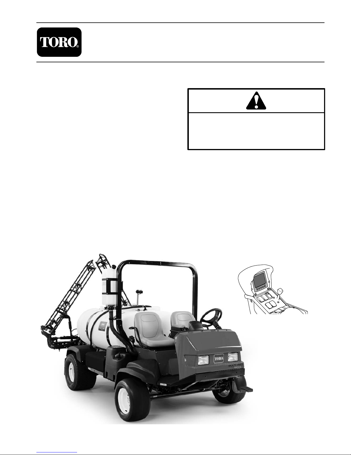
Multi Pro 5800 machines serial number above
316000000. Equipment model numbers covered in this
manual include 41393, 41394, 41593 and 41594. All of
these models include a 5 button InfoCenter display on
the control arm. Models 41394 and 41594 comply with
EPA Tier 4 emission regulations. This manual also
supports the optional GeoLink Spray System models
41623, 41624, 41625, 41630 and 41632, and optional
Ultra−Sonic Boom Leveling Kit model 41219.
REFER TO THE OPERA TOR’S MANUAL FOR OPERATING, MAINTENANCE, AND ADJUSTMENT
INSTRUCTIONS. Space is provided in Chapter 2 of this
book to insert the Operator ’s Manual, Software Guide
and Parts Catalog for your machine. Additional copies
of these and other product support publications are
available at www.Toro.com.
PART NO. 16232SL
Service Manual
(Machine Serial Numbers Above 316000000)
Multi ProR 5800
This safety symbol means DANGER, WARNING,
or CAUTION, PERSONAL SAFETY INSTRUCTION. When you see this symbol, carefully read
the instructions that follow. Failure to obey the
instructions may result in personal injury.
NOTE: A NOTE will give general information about the
correct operation, maintenance, service, testing, or repair of the machine.
IMPORTANT: The IMPORTANT notice will give important instructions which must be followed to prevent damage to systems or components on the
machine.
The Toro Company reserves the right to change product
specifications or this publication without notice.
5 Button InfoCenter Display
E The Toro Company − 2017
Page 2

This page is intentionally blank.
Multi Pro 5800
Page 3

Table Of Contents
Chapter 1 − Safety
Safety Instructions 1 − 2..........................
Jacking Instructions 1 − 5.........................
Safety and Instruction Decals 1 − 5................
Chapter 2 − Product Records and Maintenance
Product Records 2 − 1...........................
Maintenance 2 − 1...............................
Equivalents and Conversions 2 − 2................
Torque Specifications 2 − 3.......................
Chapter 6 − Electrical System
General Information 6 − 2........................
Electrical Drawings 6 − 4.........................
Special Tools 6 − 5..............................
InfoCenter Display 6 − 8..........................
Troubleshooting 6 − 29...........................
Electrical System Quick Checks 6 − 38.............
Adjustments 6 − 40..............................
Component Testing 6 − 41........................
Service and Repairs 6 − 95.......................
SafetyProduct Records
and Maintenance
Chapter 3 − Kubota Diesel Engine
Specifications 3 − 2..............................
General Information 3 − 3........................
Adjustments 3 − 4...............................
Service and Repairs 3 − 6........................
KUBOTA WORKSHOP MANUAL, DIESEL ENGINE,
05−E3B SERIES
Chapter 4 − Kubota Gasoline Engine
Specifications 4 − 2..............................
General Information 4 − 3........................
Service and Repairs 4 − 6........................
KUBOTA WORKSHOP MANUAL,
GASOLINE ENGINE WG1605−G−E3
KUBOTA DIAGNOSIS MANUAL − ECM SYSTEM,
GASOLINE ENGINE WG1605−G−E3
Chapter 5 − Hydraulic System
Specifications 5 − 3..............................
General Information 5 − 4........................
Hydraulic Schematic 5 − 9........................
Hydraulic Flow Circuits 5 − 10.....................
Special Tools 5 − 18.............................
Troubleshooting 5 − 22...........................
Testing 5 − 26...................................
Adjustments 5 − 52..............................
Service and Repairs 5 − 53.......................
EATON MODEL 72400 SERVO CONTROLLED
PISTON PUMP REPAIR INFORMATION
EATON MODEL 74318 and 74348 PISTON MOTORS:
FIXED DISPLACEMENT, VALVE PLATE DESIGN
REPAIR INFORMATION
PARKER TORQLINKTM SERVICE PROCEDURE
SAUER/DANFOSS STEERING UNIT TYPE OSPM
SERVICE MANUAL
Chapter 7 − ExcelaRate Spray System
Specifications 7 − 2..............................
General Information 7 − 3........................
Special Tools 7 − 4..............................
ExcelaRate Spray System Diagram 7 − 6...........
ExcelaRate Spray System Operation 7 − 7..........
InfoCenter Display 7 − 9..........................
Troubleshooting 7 − 26...........................
Service and Repairs 7 − 31.......................
Chapter 8 − GeoLink Spray System
Specifications 8 − 2..............................
General Information 8 − 3........................
Special Tools 8 − 5..............................
GeoLink Spray System Diagram 8 − 6..............
GeoLink Spray System Operation 8 − 7............
X25 and X30 Control Console Screens 8 − 11.......
InfoCenter Display 8 − 27.........................
Troubleshooting 8 − 39...........................
Adjustments 8 − 48..............................
Service and Repairs 8 − 51.......................
Chapter 9 − Chassis
Specifications 9 − 2..............................
General Information 9 − 2........................
Service and Repairs 9 − 3........................
Chapter 10 − Ultra Sonic Boom Kit (Optional)
General Information 10 − 2.......................
Hydraulic Schematic 10 − 4.......................
Electrical Schematic 10 − 5.......................
Ultra Sonic Boom System Operation 10 − 6.........
Troubleshooting 10 − 16.........................
Service and Repairs 10 − 19.....................
Chapter 11 − Foldout Drawings
Hydraulic Schematic 11 − 3.......................
Electrical Schematics 11 − 4......................
Wire Harness Drawings 11 − 10...................
Engine
Kubota Diesel
Engine
Kubota Gasoline
System
Hydraulic
System
Electrical
ExcelaRate
Spray System
GeoLink
Spray System
Chassis
Ultra Sonic
Boom System
Multi Pro 5800
Foldout
Drawings
Page 4

This page is intentionally blank.
Multi Pro 5800
Page 5

Table of Contents
SAFETY INSTRUCTIONS 2......................
Before Operating 2............................
While Operating 3.............................
Maintenance and Service 4....................
JACKING INSTRUCTIONS 5.....................
SAFETY AND INSTRUCTION DECALS 5..........
Safety
Chapter 1
Safety
Multi Pro 5800 Page 1 − 1 Safety
Page 6

Safety Instructions
The Multi Pro 5800 Turf Sprayer is designed and tested
to offer safe service when operated and maintained
properly. Although hazard control and accident prevention are partially dependent upon the design and configuration of the machine, these factors are also
dependent upon the awareness, concern and proper
training of the personnel involved in the operation, transport, maintenance and storage of the machine. Improper use or maintenance of the machine can result in injury
Before Operating
1. Read and un d e r s t a n d t h e c o ntents of the Operator’s
Manual before starting and operating the machine. Become familiar with the controls and know how to stop the
machine and engine quickly. Additional copies of the
Operator’s Manual are available on the internet at
www.Toro.com.
2. Keep all shields, safety devices and decals in place.
If a shield, safety device or decal is defective, illegible
or damaged, repair or replace it before operating the
machine. Also tighten any loose nuts, bolts or screws to
ensure machine is in safe operating condition.
or death. To reduce the potential for injury or death,
comply with the following safety instructions.
WARNING
To reduce the potential for injury or death, comply with the following safety instructions.
NOTE: All of the interlock switches must be functioning
and adjusted correctly for the engine to start (see Chapter 6 − Electrical System in this manual for switch adjustment and testing information).
4. Since diesel fuel is flammable, handle it carefully:
A. Store fuel in containers specifically designed for
this purpose.
B. Do not remove machine fuel tank cap while en-
gine is hot or running.
3. Various safety interlocks incorporated into the system prevent the engine from starting unless the following conditions are met:
S The spray pump enable switch is in the OFF
position
S If an optional tank rinse kit is installed, the rinse
pump enable switch is in the OFF position
S The seat switch is depressed indicating an Operator is present, or the parking brake is engaged
S The neutral switch indicates the traction pump
is in neutral
C. Do not smoke while handling fuel.
D. Fill fuel tank outdoors and only to within an inch of
the top of the tank, not the filler neck. Do not overfill
the fuel tank and wipe up any spilled fuel.
Multi Pro 5800Page 1 − 2Safety
Page 7

While Operating
Safety
1. Sit on the operators seat while the machine is in motion, or engage the parking brake during stationary operation.
2. The engine will stop running it the vehicle is operated
for more than ten seconds with the parking brake engaged.
3. Do not run engine in a confined area without adequate ventilation. Exhaust fumes are hazardous and
could possibly be deadly.
4. Do not touch engine, radiator, muffler or exhaust
pipe while engine is running or soon after it is stopped.
These areas could be hot enough to cause burns.
5. Follow spray chemical manufacturer’s recommendations for handling precautions, protective equipment
and mixing proportions.
6. Before stopping the engine:
A. Ensure that traction pedal is in the NEUTRAL
position.
B. Engage the parking brake.
C. Set spray pump enable switch to the OFF posi-
tion.
D. If an optional tank rinse kit is installed, set the
rinse pump enable switch to the OFF position
7. Do not park on slopes unless wheels are chocked or
blocked.
Multi Pro 5800 Page 1 − 3 Safety
Page 8

Maintenance and Service
1. Before servicing or making adjustments, turn spray
pump off, put traction pedal in neutral, stop engine, set
parking brake and remove key from the switch.
2. Prior to servicing sprayer components, determine
what chemical(s) have been used in the sprayer. Follow
precautions and recommendations printed on chemical
container labels or Material Safety Data Sheets when
servicing sprayer components. Use appropriate protective equipment: protective clothing, chemical resistant
gloves and eye protection.
3. Make sure machine is in safe operating condition by
keeping all nuts, bolts and screws tight.
4. Never store the machine or fuel container inside
where there is an open flame, such as near a water heater or furnace.
5. Make sure all hydraulic line connectors are tight and
that all hydraulic hoses and lines are in good condition,
before applying pressure to the system.
6. Keep body and hands away from pin hole leaks in hydraulic lines that eject high pressure hydraulic fluid. Use
cardboard or paper to find hydraulic leaks. Hydraulic
fluid escaping under pressure can penetrate skin and
cause injury. Fluid accidentally injected into the skin
must be surgically removed within a few hours by a doctor familiar with this form of injury or gangrene may result.
10.If engine must be running to perform maintenance or
an adjustment, keep clothing, hands, feet and other
parts of the body away from moving parts. Keep bystanders away.
11.Do not overspeed the engine. To assure safety and
accuracy, check maximum engine speed.
12.Shut engine off before checking or adding oil to the
crankcase.
13.Disconnect battery before servicing the machine.
Disconnect negative (−) battery cable first and positive
(+) cable last. If battery voltage is required for troubleshooting or test procedures, temporarily connect the
battery. Reconnect positive (+) cable first and negative
(−) cable last.
14.Battery acid is poisonous and can cause burns.
Avoid contact with skin, eyes and clothing. Protect your
face, eyes and clothing when working with a battery.
15.Battery gases can explode. Keep cigarettes, sparks
and flames away from the battery.
16.To assure optimum performance and continued
safety of the machine, use genuine Toro replacement
parts and accessories. Replacement parts and accessories made by other manufacturers may result in nonconformance with safety standards and the warranty
may be voided.
7. Before disconnecting or performing any work on the
hydraulic system, all pressure in hydraulic system must
be relieved. To relieve system pressure, rotate steering
wheel in both directions after the key switch has been
turned off.
8. If major repairs are ever needed or assistance is desired, contact an Authorized Toro Distributor.
9. To reduce potential fire hazard, keep engine area
free of excessive grease, grass, leaves and dirt. Clean
protective screen on machine frequently.
17.When changing attachments, tires or performing
other service, use correct supports, hoists and jacks.
Make sure machine is parked on a solid level floor such
as a concrete floor. Prior to raising the machine, remove
any attachments that may interfere with the safe and
proper raising of the machine. Always chock or block
wheels. Use jack stands or appropriate load holding devices to support the raised machine. If the machine is
not properly supported, the machine may move or fall,
which may result in personal injury (see Jacking Instructions in this section).
Multi Pro 5800Page 1 − 4Safety
Page 9
Jacking Instructions
CAUTION
When changing attachments, tires or performing other service, use correct supports, hoists
and jacks. Make sure machine is parked on a
solid, level surface such as a concrete floor.
Prior to raising machine, remove any attachments that may interfere with the safe and proper raising of the machine. Always chock or
block wheels. Use jack stands or other appropriate load holding devices to support the
raised machine. If the machine is not properly
supported, the machine may move or fall,
which may result in personal injury.
Jacking the Front End
1. Set parking brake and chock both rear tires to prevent the machine from moving.
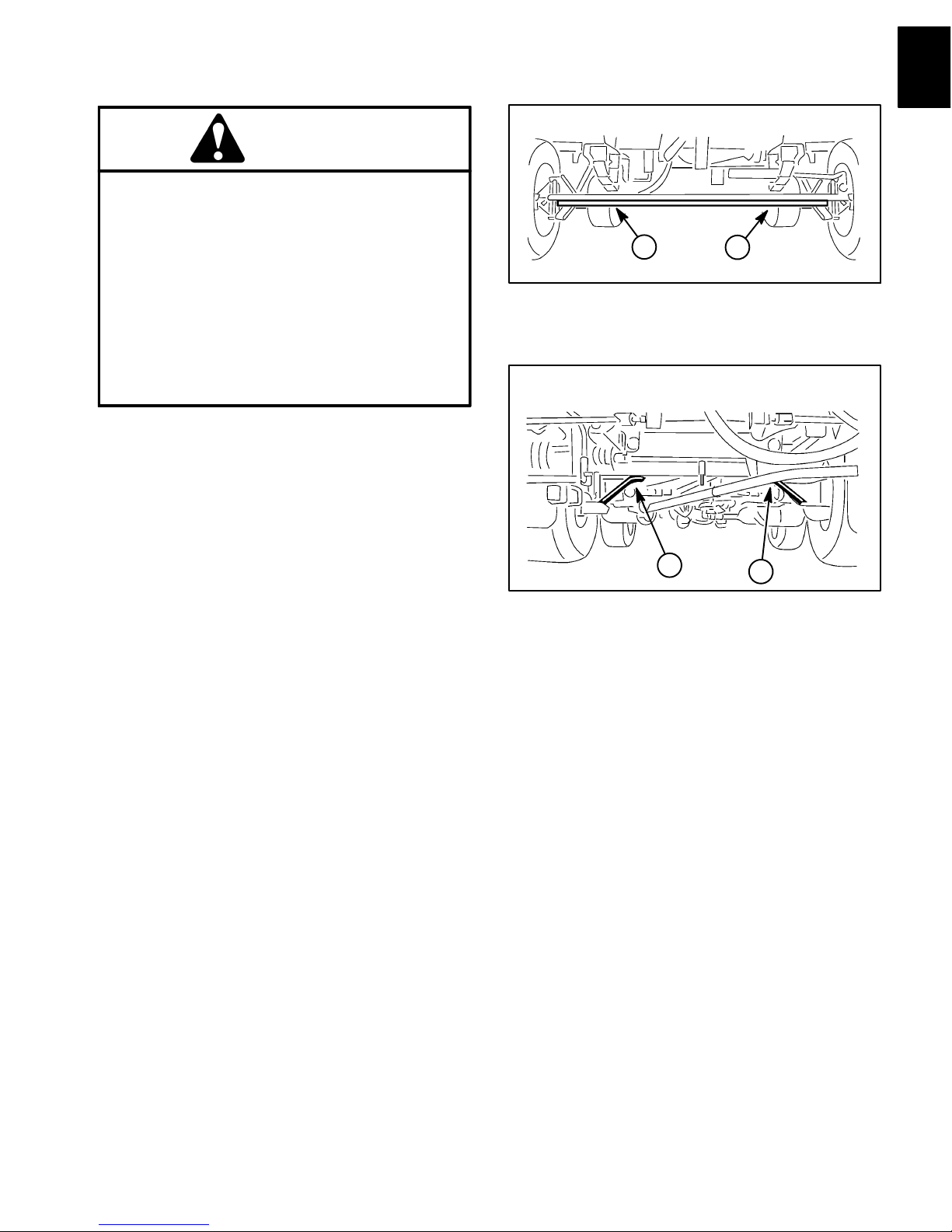
2. Position jack securely under the front axle, directly
beneath the leaf springs (Fig. 1).
1
Figure 1
1. Front jacking points
1
Safety
3. Jack front of machine off the ground.
4. Position jack stands under the front axle as close to
the wheel as possible to support the machine.
Jacking the Rear End
1. Set parking brake and chock both front tires to prevent the machine from moving.
2. Place jack securely under the rear most frame supports between the angle welds (Fig. 2).
3. Jack rear of machine off the ground.
4. Position jack stands under the frame to support the
machine.
Safety and Instruction Decals
Numerous safety and instruction decals are affixed to
the Multi Pro 5800. If any decal becomes illegible or
damaged, install a new decal. Part numbers are listed
in your Parts Catalog. Order replacement decals from
your Authorized Toro Distributor.
1
Figure 2
1. Rear jacking points
1
Multi Pro 5800 Page 1 − 5 Safety
Page 10

This page is intentionally blank.
Multi Pro 5800Page 1 − 6Safety
Page 11

Chapter 2
Product Records and Maintenance
Table of Contents
PRODUCT RECORDS 1.........................
MAINTENANCE 1..............................
EQUIVALENTS AND CONVERSIONS 2...........
Decimal and Millimeter Equivalents 2............
U.S. to Metric Conversions 2...................
TORQUE SPECIFICATIONS 3...................
Fastener Identification 3.......................
Using a Torque Wrench with an Offset Wrench 3..
Standard Torque for Dry, Zinc Plated and
Steel Fasteners (Inch Series Fasteners) 4......
Standard Torque for Dry, Zinc Plated and
Steel Fasteners (Metric Fasteners) 5..........
Other Torque Specifications 6..................
Conversion Factors 6.........................
Product Records
Insert Operator’s Manual and Parts Catalog for your
Multi Pro 5800 at the end of this chapter. Additionally, if
any optional equipment has been installed to your
sprayer, insert the Installation Instructions, Operator’s
Manuals and Parts Catalogs for those options at the end
of this chapter.
Product Records
and Maintenance
Maintenance
Maintenance procedures and recommended service intervals for the Multi Pro 5800 are covered in the Operator’s Manual. Refer to that publication when performing
regular equipment maintenance. Several maintenance
procedures have break−in intervals identified in the Operator’s Manual. Refer to the Engine Operator’s Manual
for additional engine specific maintenance procedures.
Multi Pro 5800 Page 2 − 1 Product Records and Maintenance
Page 12

Equivalents and Conversions
0.09375
Multi Pro 5800Page 2 − 2Product Records and Maintenance
Page 13

Torque Specifications
Recommended fastener torque values are listed in the
following tables. For critical applications, as determined
by Toro, either the recommended torque or a torque that
is unique to the application is clearly identified and specified in this Service Manual.
These Torque Specifications for the installation and
tightening of fasteners shall apply to all fasteners which
do not have a specific requirement identified in this Service Manual. The following factors shall be considered
when applying torque: cleanliness of the fastener, use
of a thread sealant (e.g. Loctite), degree of lubrication
on the fastener, presence of a prevailing torque feature,
hardness of the surface underneath the fastener’s head
or similar condition which affects the installation.
Fastener Identification
As noted in the following tables, torque values should be
reduced by 25% for lubricated fasteners to achieve
the similar stress as a dry fastener. Torque values may
also have to be reduced when the fastener is threaded
into aluminum or brass. The specific torque value
should be determined based on the aluminum or brass
material strength, fastener size, length of thread engagement, etc.
The standard method of verifying torque shall be performed by marking a line on the fastener (head or nut)
and mating part, then back off fastener 1/4 of a turn.
Measure the torque required to tighten the fastener until
the lines match up.
Product Records
and Maintenance
Grade 1 Grade 5 Grade 8
Inch Series Bolts and Screws
Figure 1
Using a Torque Wrench with an Offset Wrench
Use of an offset wrench (e.g. crowfoot wrench) will affect
torque wrench calibration due to the effective change of
torque wrench length. When using a torque wrench with
an offset wrench, multiply the listed torque recommendation by the calculated torque conversion factor (Fig.
3) to determine proper tightening torque. Tightening
torque when using a torque wrench with an offset
wrench will be lower than the listed torque recommendation.
Example: The measured effective length of the torque
wrench (distance from the center of the handle to the
center of the square drive) is 18”.
The measured effective length of the torque wrench with
the offset wrench installed (distance from the center of
the handle to the center of the offset wrench) is 19”.
Class 8.8 Class 10.9
Metric Bolts and Screws
Figure 2
If the listed torque recommendation for a fastener is
from 76 to 94 ft−lb, the proper torque when using this
torque wrench with an offset wrench would be from 72
to 89 ft−lb.
(effective length of
torque wrench)
A
B
(effective length of torque
wrench + offset wrench)
TORQUE CONVERSION FACTOR = A / B
Torque wrenchOffset wrench
The calculated torque conversion factor for this torque
wrench with this offset wrench would be 18 / 19 = 0.947.
Multi Pro 5800 Page 2 − 3 Product Records and Maintenance
Figure 3
Page 14

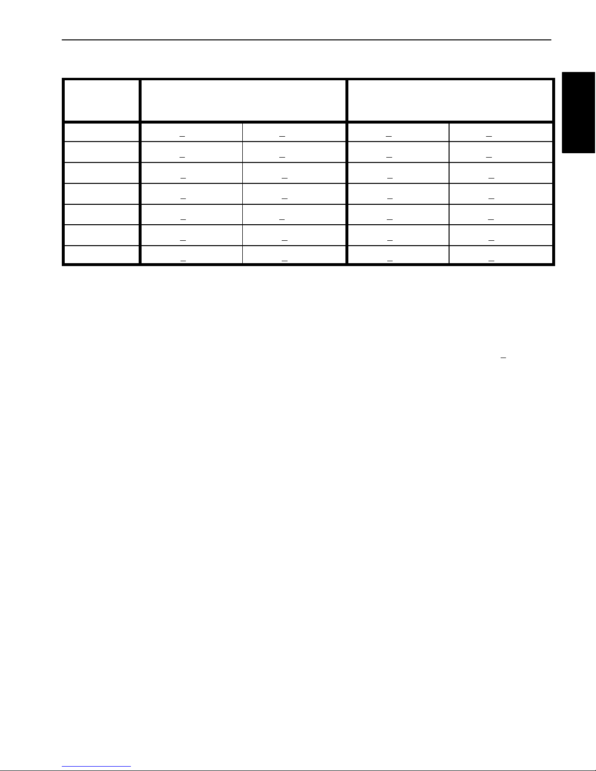
Standard Torque for Dry, Zinc Plated and Steel Fasteners (Inch Series Fasteners)
Thread Size
# 6 − 32 UNC
# 6 − 40 UNF 17 + 2 190 + 20 25 + 2 280 + 20
# 8 − 32 UNC
# 8 − 36 UNF 31 + 3 350 + 30 43 + 4 485 + 45
# 10 − 24 UNC
# 10 − 32 UNF 48 + 4 540 + 45 68 + 6 765 + 70
1/4 − 20 UNC 48 + 7 53 + 7 599 + 79 100 + 10 1125 + 100 140 + 15 1580 + 170
1/4 − 28 UNF 53 + 7 65 + 10 734 + 113 115 + 10 1300 + 100 160 + 15 1800 + 170
5/16 − 18 UNC 115 + 15 105 + 17 1186 + 169 200 + 25 2250 + 280 300 + 30 3390 + 340
5/16 − 24 UNF 138 + 17 128 + 17 1446 + 192 225 + 25 2540 + 280 325 + 30 3670 + 340
3/8 − 16 UNC 16 + 2 16 + 2 22 + 3 30 + 3 41 + 4 43 + 4 58 + 5
Grade 1, 5, &
8 with Thin
Height Nuts
in−lb in−lb N−cm in−lb N−cm in−lb N−cm
10 + 2 13 + 2 147 + 23
13 + 2 25 + 5 282 + 30
18 + 2 30 + 5 339 + 56
ft−lb ft−lb N−m ft−lb N−m ft−lb N−m
SAE Grade 1 Bolts, Screws, Studs, &
Sems with Regular Height Nuts
(SAE J995 Grade 2 or Stronger Nuts)
SAE Grade 5 Bolts, Screws, Studs, &
Sems with Regular Height Nuts
(SAE J995 Grade 2 or Stronger Nuts)
15 + 2 170 + 20 23 + 2 260 + 20
29 + 3 330 + 30 41 + 4 460 + 45
42 + 4 475 + 45 60 + 6 675 + 70
SAE Grade 8 Bolts, Screws, Studs, &
Sems with Regular Height Nuts
(SAE J995 Grade 5 or Stronger Nuts)
3/8 − 24 UNF 17 + 2 18 + 2 24 + 3 35 + 3 47 + 4 50 + 4 68 + 5
7/16 − 14 UNC 27 + 3 27 + 3 37 + 4 50 + 5 68 + 7 70 + 7 95 + 9
7/16 − 20 UNF 29 + 3 29 + 3 39 + 4 55 + 5 75 + 7 77 + 7 104 + 9
1/2 − 13 UNC 30 + 3 48 + 7 65 + 9 75 + 8 102 + 11 105 + 10 142 + 14
1/2 − 20 UNF 32 + 3 53 + 7 72 + 9 85 + 8 115 + 11 120 + 10 163 + 14
5/8 − 11 UNC 65 + 10 88 + 12 119 + 16 150 + 15 203 + 20 210 + 20 285 + 27
5/8 − 18 UNF 75 + 10 95 + 15 129 + 20 170 + 15 230 + 20 240 + 20 325 + 27
3/4 − 10 UNC 93 + 12 140 + 20 190 + 27 265 + 25 359 + 34 375 + 35 508 + 47
3/4 − 16 UNF 115 + 15 165 + 25 224 + 34 300 + 25 407 + 34 420 + 35 569 + 47
7/8 − 9 UNC 140 + 20 225 + 25 305 + 34 430 + 45 583 + 61 600 + 60 813 + 81
7/8 − 14 UNF 155 + 25 260 + 30 353 + 41 475 + 45 644 + 61 660 + 60 895 + 81
NOTE: Reduce torque values listed in the table above
by 25% for lubricated fasteners. Lubricated fasteners
on the fastener size, the aluminum or base material
strength, length of thread engagement, etc.
are defined as threads coated with a lubricant such as
oil, graphite or thread sealant (e.g. Loctite).
NOTE: The nominal torque values listed above for
Grade 5 and 8 fasteners are based on 75% of the miniNOTE: Torque values may have to be reduced when
installing fasteners into threaded aluminum or brass.
The specific torque value should be determined based
mum proof load specified in SAE J429. The tolerance is
approximately +
10% of the nominal torque value. Thin
height nuts include jam nuts.
Multi Pro 5800Page 2 − 4Product Records and Maintenance
Page 15
Standard Torque for Dry, Zinc Plated and Steel Fasteners (Metric Fasteners)
Thread Size
Class 8.8 Bolts, Screws, and Studs with
Regular Height Nuts
(Class 8 or Stronger Nuts)
Class 10.9 Bolts, Screws, and Studs with
Regular Height Nuts
(Class 10 or Stronger Nuts)
M5 X 0.8 57 + 5 in−lb 640 + 60 N−cm 78 + 7 in−lb 885 + 80 N−cm
M6 X 1.0 96 + 9 in−lb 1018 + 100 N−cm 133 + 13 in−lb 1500 + 150 N−cm
M8 X 1.25 19 + 2 ft−lb 26 + 3 N−m 27 + 2 ft−lb 36 + 3 N−m
M10 X 1.5 38 + 4 ft−lb 52 + 5 N−m 53 + 5 ft−lb 72 + 7 N−m
M12 X 1.75 66 + 7 ft−lb 90 + 10 N−m 92 + 9 ft−lb 125 + 12 N−m
M16 X 2.0 166 + 15 ft−lb 225 + 20 N−m 229 + 22 ft−lb 310 + 30 N−m
M20 X 2.5 325 + 33 ft−lb 440 + 45 N−m 450 + 37 ft−lb 610 + 50 N−m
NOTE: Reduce torque values listed in the table above
by 25% for lubricated fasteners. Lubricated fasteners
on the fastener size, the aluminum or base material
strength, length of thread engagement, etc.
are defined as threads coated with a lubricant such as
oil, graphite or thread sealant (e.g. Loctite).
NOTE: The nominal torque values listed above are
NOTE: Torque values may have to be reduced when
installing fasteners into threaded aluminum or brass.
The specific torque value should be determined based
based on 75% of the minimum proof load specified in
SAE J1199. The tolerance is approximately +
nominal torque value.
10% of the
Product Records
and Maintenance
Multi Pro 5800 Page 2 − 5 Product Records and Maintenance
Page 16
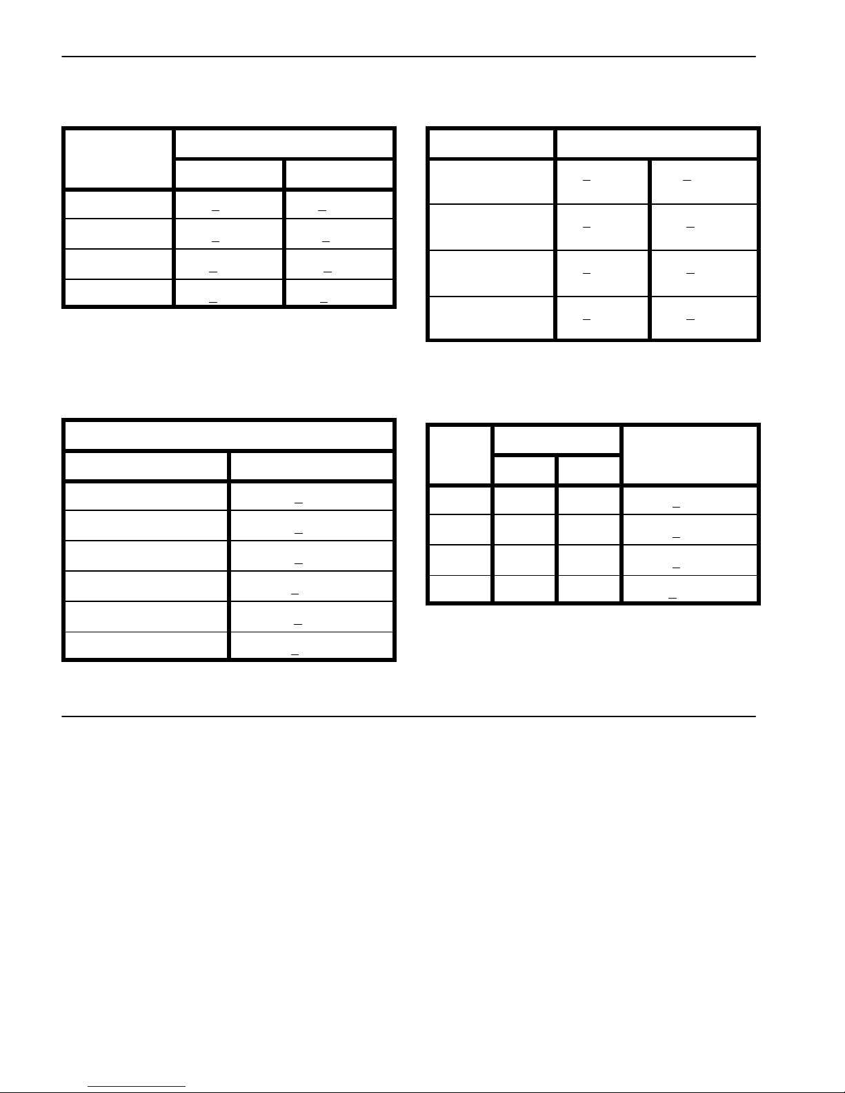
Other Torque Specifications
SAE Grade 8 Steel Set Screws
Recommended Torque
Thread Size
Square Head Hex Socket
1/4 − 20 UNC 140 + 20 in−lb 73 + 12 in−lb
5/16 − 18 UNC 215 + 35 in−lb 145 + 20 in−lb
3/8 − 16 UNC 35 + 10 ft−lb 18 + 3 ft−lb
1/2 − 13 UNC 75 + 15 ft−lb 50 + 10 ft−lb
Thread Cutting Screws
(Zinc Plated Steel)
Type 1, Type 23 or Type F
Thread Size Baseline Torque*
No. 6 − 32 UNC 20 + 5 in−lb
Wheel Bolts and Lug Nuts
Thread Size
7/16 − 20 UNF
Grade 5
1/2 − 20 UNF
Grade 5
M12 X 1.25
Class 8.8
M12 X 1.5
Class 8.8
** For steel wheels and non−lubricated fasteners.
Thread Cutting Screws
(Zinc Plated Steel)
Thread
Size
No. 6 18 20 20 + 5 in−lb
Threads per Inch
Type A Type B
Recommended Torque**
65 + 10 ft−lb 88 + 14 N−m
80 + 10 ft−lb 108 + 14 N−m
80 + 10 ft−lb 108 + 14 N−m
80 + 10 ft−lb 108 + 14 N−m
Baseline Torque*
No. 8 − 32 UNC 30 + 5 in−lb
No. 10 − 24 UNC 38 + 7 in−lb
1/4 − 20 UNC 85 + 15 in−lb
5/16 − 18 UNC 110 + 20 in−lb
3/8 − 16 UNC 200 + 100 in−lb
Conversion Factors
in−lb X 11.2985 = N−cm N−cm X 0.08851 = in−lb
ft−lb X 1.3558 = N−m N−m X 0.7376 = ft−lb
No. 8 15 18 30 + 5 in−lb
No. 10 12 16 38 + 7 in−lb
No. 12 11 14 85 + 15 in−lb
* Hole size, material strength, material thickness & finish
must be considered when determining specific torque
values. All torque values are based on non−lubricated
fasteners.
Multi Pro 5800Page 2 − 6Product Records and Maintenance
Page 17

Table of Contents
SPECIFICATIONS 2............................
GENERAL INFORMATION 3.....................
Operator’s Manual 3..........................
Kubota Workshop Manual 3....................
ADJUSTMENTS 4..............................
Adjust Throttle Cable 4........................
SERVICE AND REPAIRS 6......................
Fuel System 6................................
Air Cleaner 8.................................
Exhaust System 10...........................
Radiator 12..................................
Engine 16....................................
Removal 16.................................
Installation 19...............................
Flywheel Coupler 22...........................
KUBOTA WORKSHOP MANUAL, DIESEL ENGINE,
05−E3B SERIES
Chapter 3
Kubota Diesel Engine
Engine
Kubota Diesel
Multi Pro 5800−D Page 3 − 1 Kubota Diesel Engine
Page 18

Specifications
Item Description
Make / Designation V1505−E3B, Kubota, 4−Cycle, 4 Cylinder,
Bore x Stroke 3.07 in x 3.09 in (78 mm x 78.4 mm)
Total Displacement 91.4 in3 (1498 cc)
Compression Ratio 23:1
Firing Order 1 − 3 − 4 − 2 (numbers start at fan end)
Low Idle (no load) 1200 to 1300 RPM
High Idle (no load) 3050 to 3150 RPM
Direction of Rotation Counterclockwise (Viewed from Flywheel)
Fuel No. 2−D Diesel Fuel (ASTM D975)
Fuel Injection Pump Bosch MD Type Mini Pump
Injection Nozzles Mini Nozzle (DNOPD)
Fuel Tank Capacity 12 U.S. gallons (45 liters)
Governor Centrifugal Mechanical
Water Cooled, Diesel Engine
Engine Oil API Classification CH−4, CI−4 or Higher
Oil Pump Trochoid Type
Engine Oil Capacity (approximate) 4.9 U.S. quarts (4.6 liters) with Filter
Cooling System Capacity (approximate − including reserve tank) 5.9 U.S. quarts (5.6 liters)
Starter 12 VDC, 1.2 KW
Alternator/Regulator 12 VDC 60 AMP
Engine Dry Weight (approximate) 242 lbs (110 kg)
(see Operator’s Manual for viscosity recommendations)
Multi Pro 5800−DPage 3 − 2Kubota Diesel Engine
Page 19

General Information
This Chapter gives information about specifications, adjustments and repair of the Kubota Diesel engine that
powers the Multi Pro 5800−D.
Operator ’s Manual
The Operator’s Manual provides information regarding
the operation, general maintenance and maintenance
intervals for the Kubota diesel engine that powers your
Multi Pro 5800−D. Refer to that publication for additional
information when servicing the machine.
Kubota Workshop Manual
Engine
Kubota Diesel
General maintenance procedures are described in your
Operator’s Manual. Information on engine testing, disassembly and reassembly is identified in the Kubota
Workshop Manual Diesel Engine, 05−E3B Series that i s
included at the end of this chapter. Make sure that the
correct engine manual is used when servicing the engine on your Multi Pro.
Most engine repairs and adjustments require tools
which are commonly available in many service shops.
Special tools are described in the Kubota Workshop
Manual Diesel Engine, 05−E3B Series. The use of some
specialized test equipment is explained. However, the
cost of the test equipment and the specialized nature of
some repairs may dictate that the work be done at an
engine repair facility.
Multi Pro 5800−D Page 3 − 3 Kubota Diesel Engine
Page 20

Adjustments
Adjust Throttle Cable
Proper engine RPM and machine performance is dependent upon proper adjustment of throttle cable.
NOTE: The throttle cable swivel should be positioned
in the lowest hole in the speed control lever.
1
5
2
1. Move throttle control lever on control console fully
forward to FAST position.
2. Check position of the engine speed control lever on
fuel injection pump. The speed control lever should be
contacting the high speed screw when the throttle control lever is in the fully forward FAST position.
3. If necessary, throttle cable can be adjusted by loosening cable clamp screw and repositioning cable until
speed control lever contacts high speed screw when the
throttle control lever is in the fully forward FAST position.
Tighten cable clamp screw after adjustment has been
completed.
4. After securing cable clamp, make sure that cable adjustment is still correct. Ensure the throttle swivel moves
freely and the speed control lever travels fully from stop
to stop.
VIEW FROM ABOVE
1. Throttle cable
2. High speed screw
3. Speed control lever
3
4
Figure 1
4. Throttle swivel
5. Cable clamp
Multi Pro 5800−DPage 3 − 4Kubota Diesel Engine
Page 21

This page is intentionally blank.
Engine
Kubota Diesel
Multi Pro 5800−D Page 3 − 5 Kubota Diesel Engine
Page 22
Service and Repairs
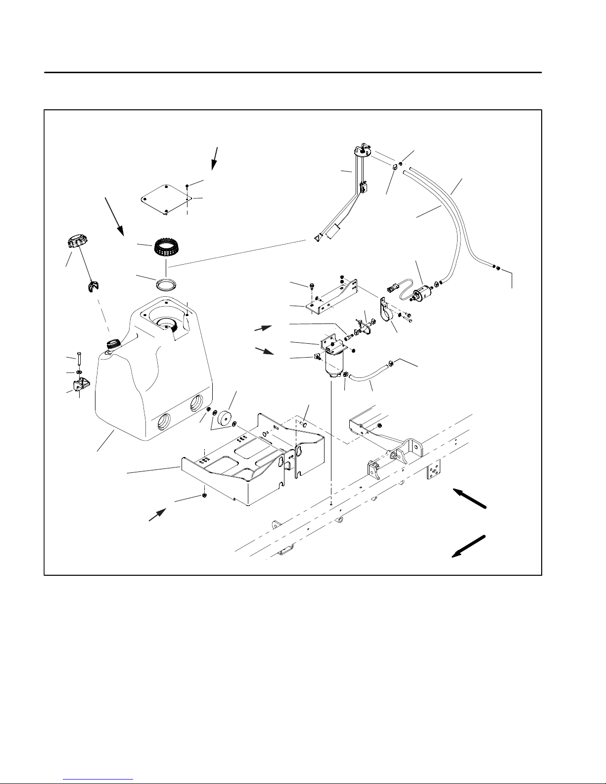
Fuel System
10 to 12 in−lb
(1 N−m)
17
13 to 65 in−lb
(1 to 7 N−m)
10
9
6
8
15
14
12
16
18
19
13
20
11
Apply
Thread
Sealant
28
27
26
25
22
FROM
FUEL
RAIL
21
24
TO
5
16
4
7
6
23
INJECTION
PUMP
1
2
25 in−lb (3 N−m)
1. Fuel tank
2. Base
3. Flange nut (2)
4. Carriage bolt (2)
5. Rubber bumper (2)
6. Flat washer (6)
7. Flange nut (2)
8. Clamp (2)
9. Cap screw (2)
10. Fuel fill cap
3
RIGHT
FRONT
Figure 2
11. Gasket
12. Fuel pickup/level sender
13. Fuel pickup/level sender cap
14. Tank cover
15. Flange head screw (4)
16. Hose clamp (6)
17. Hose clamp (2)
18. Fuel hose − return
19. Fuel hose − supply
20. Fuel pump
21. Fuel pump clamp
22. Fuel hose − supply
23. Fuel hose − supply
24. Elbow fitting
25. Fuel filter/separator
26. Straight fitting
27. Bracket
28. Flange head screw (2)
Multi Pro 5800−DPage 3 − 6Kubota Diesel Engine
Page 23
Fuel Tank Installation (Fig. 2)
DANGER
Because diesel fuel is highly flammable, use
caution when storing or handling it. Do not
smoke while filling the fuel tank. Do not fill fuel
tank while engine is running, hot or when machine is in an enclosed area. Always fill fuel tank
outside and wipe up any spilled fuel before starting the engine. Store fuel in a clean, safety−approved container and keep cap in place. Use diesel fuel for the engine only; not for any other
purpose.
Check Fuel Lines and Connections
Check fuel lines and connections periodically as recommended in the Operator’s Manual. Check lines for deterioration, damage, leaks or loose connections. Replace
hoses, clamps and connections as necessary.
Empty and Clean Fuel Tank
Empty and clean the fuel tank if the fuel system becomes contaminated or if the machine is to be stored for
an extended period.
1. If fuel hoses were removed from machine, route fuel
hoses through machine as recorded during removal.
Make sure that clearance exists between fuel hoses and
machine components along full length of hoses.
2. Secure fuel tank to machine with two (2) clamps at
base. Tighten clamp fasteners to 25 in−lbs (3 N−m).
3. Install fuel pickup/level sender if previously removed
from tank. Tighten fuel pickup/level sender cap from 13
to 65 in−lbs (1 to 7 N−m).
4. Connect fuel hoses to top of fuel tank and secure
with hose clamps.
5. Connect the fuel pickup/level sender to the machine
wire harness.
6. Install fuel tank cover and tighten cover screws from
10 to 12 in−lbs (1 N−m).
7. Fill fuel tank and bleed air from the fuel system (see
machine Operator’s Manual).
8. Start engine and check fuel line connections for
leaks.
Engine
Kubota Diesel
To clean fuel tank, flush tank out with clean solvent.
Make sure tank is free of contaminates and debris.
Fuel Tank Removal (Fig. 2)
1. Park machine on a level surface, stop engine, engage parking brake and remove key from the ignition
switch.
2. Use a fuel transfer pump to remove fuel from the fuel
tank and into a suitable container.
3. Remove the fuel tank cover.
4. Disconnect the fuel pickup/level sender from the machine wire harness.
5. Loosen hose clamps that secure supply and return
hoses to top of tank. Remove hoses from tank.
6. Remove two (2) fuel tank clamps from base and remove fuel tank from machine. Check condition of fuel
tank rubber bumpers and replace if worn or damaged.
7. If necessary, remove fuel pickup/level sender from
tank. Check condition of fuel pickup/level sender gasket
and replace if worn or damaged. See Fuel Pickup/Level
Sender in Chapter − 6 Electrical System for testing information.
8. If necessary, remove fuel hoses from machine.
Record fuel hose routing for assembly purposes.
Multi Pro 5800−D Page 3 − 7 Kubota Diesel Engine
Page 24
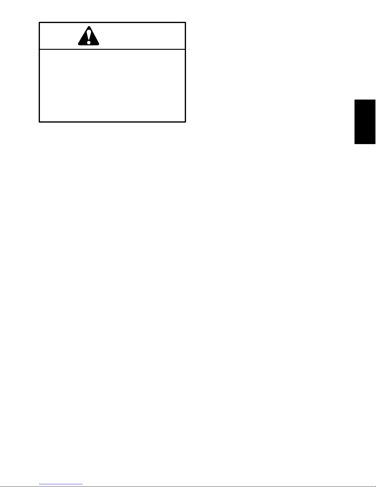
Air Cleaner
1
2
5
6
3
4
15
7
14
9
RIGHT
FRONT
1. Cap
2. Hose clamp
3. Flange head screw
4. Clamp
5. Flange nut (2)
8
13
9
9
10
11
12
Figure 3
6. Bracket
7. Flange nut
8. Hose
9. Hose clamp (3)
10. Flange head screw (2)
11. Air cleaner mount
12. Flange nut (2)
13. Hose
14. Air cleaner assembly
15. U−Bolt
Multi Pro 5800−DPage 3 − 8Kubota Diesel Engine
Page 25
Removal (Fig. 3)
NOTE: For air cleaner maintenance information, see
the machine Operator’s Manual.
1. Raise passenger seat to access air cleaner assembly.
2. Remove air cleaner components as needed.
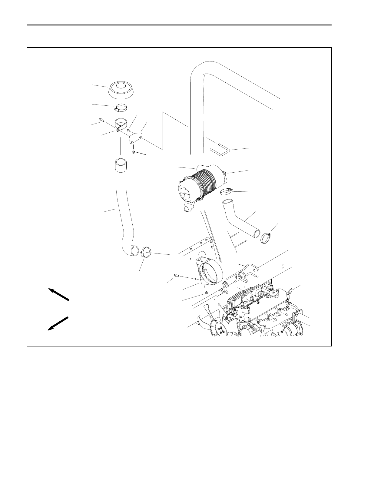
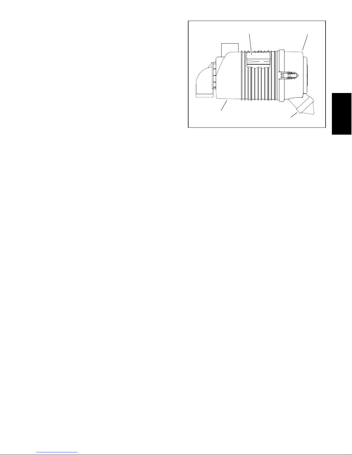
Installation (Fig. 3)
IMPORTANT: Any leaks in the air filter system will
cause serious engine damage. Make sure that all air
cleaner components are in good condition and are
properly secured during installation.
1. Assemble air cleaner system. Make sure that vacuator valve on air cleaner cover points downward after assembly (Fig. 4).
1
1. Air cleaner housing
2. Air cleaner element
2
Figure 4
3. Air cleaner cover
4. Vacuator valve
3
4
Engine
Kubota Diesel
Multi Pro 5800−D Page 3 − 9 Kubota Diesel Engine
Page 26

Exhaust System
RIGHT
FRONT
13
16
9
15
7
12
14
12
9
4
3
2
1. Exhaust pipe
2. Cap screw (4)
3. Lock washer (4)
4. Gasket
5. Muffler
6. Muffler clamp (2)
9
8
5
9
8
7
6
1
111112
10
9
Figure 5
7. Cap screw (2)
8. Flange head screw (2)
9. Flat washer (6)
10. Hanger (2)
11. Rubber hanger (3)
12. Flange nut (3)
13. Tail pipe
14. Hanger
15. Flange head screw
16. Flange nut
CAUTION
The muffler and exhaust system may be hot. To
avoid possible burns, allow the engine and exhaust system to cool before working on the exhaust system.
Multi Pro 5800−DPage 3 − 10Kubota Diesel Engine
Page 27

Removal (Fig. 5)
Installation (Fig. 5)
1. Park machine on a level surface, stop engine, engage parking brake and remove key from the ignition
switch.
2. Remove the rear undercarriage shroud from the machine (see Undercarriage Shrouds in Chapter 9 − Chassis in this manual).
3. Support muffler from below to prevent it from falling.
4. Remove exhaust system components as required.
During removal, note location and orientation of fasteners, rubber hangers, clamps and brackets.
5. Locate and discard gasket between exhaust pipe
and header if exhaust pipe is disconnected from header.
Clean gasket surfaces on engine exhaust manifold and
exhaust pipe.
1. If exhaust pipe was removed from engine, use a new
gasket and install exhaust pipe and fasteners finger
tight.
2. Install all remaining exhaust system components including hangers, clamps and brackets finger tight.
3. Tighten exhaust system components i n the following
order:
A. Tighten fasteners securing exhaust pipe to exhaust header.
B. Tighten exhaust system hanger and bracket fasteners. DO NOT tighten muffler clamps at this time.
C. Position the tailpipe so the outlet is parallel to the
ground and tighten muffler clamps.
4. Install the rear undercarriage shroud to the machine
(see Undercarriage Shrouds in Chapter 9 − Chassis in
this manual).
Engine
Kubota Diesel
Multi Pro 5800−D Page 3 − 11 Kubota Diesel Engine
Page 28
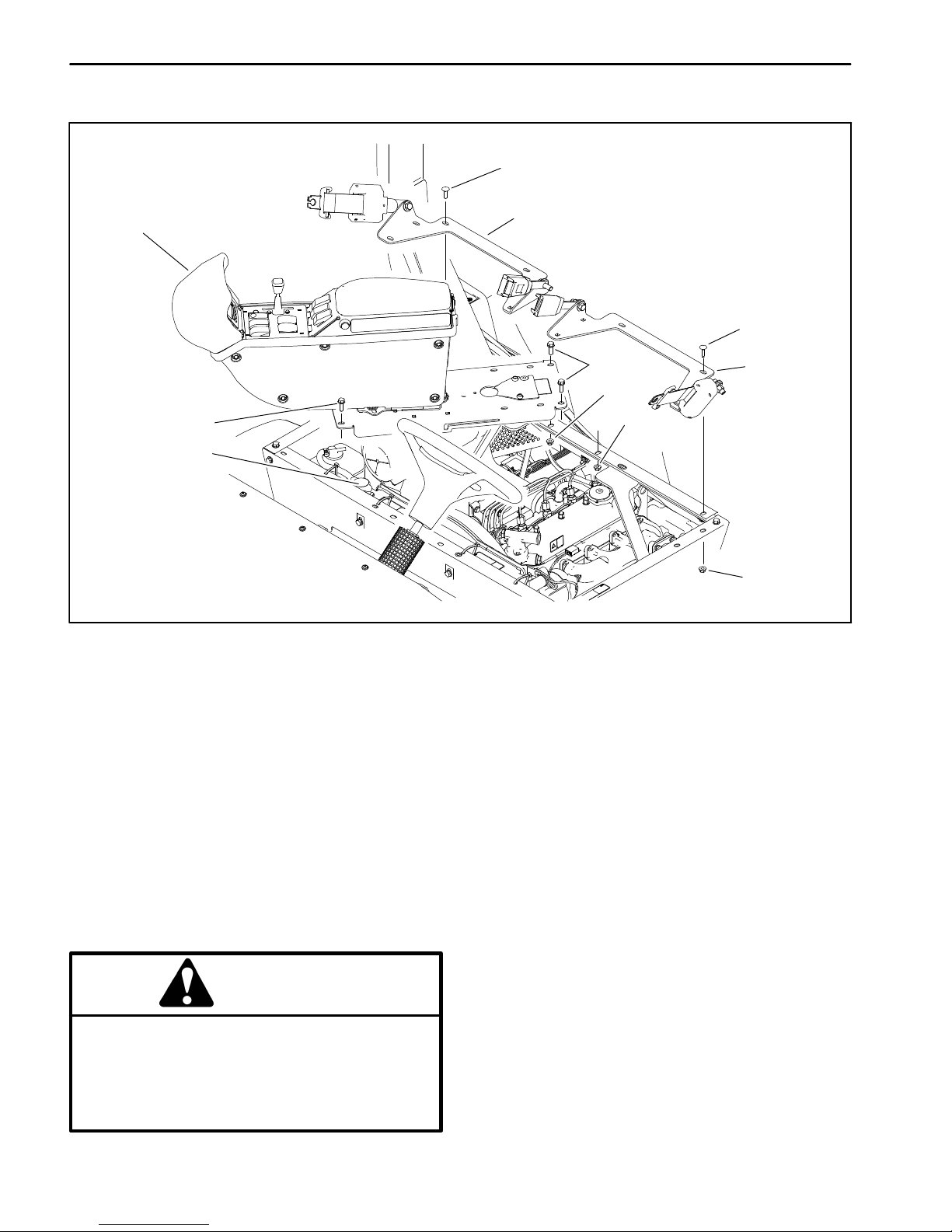
Radiator
3
1
5
6
1. Console assembly
2. Seat belt bracket assembly (2)
Figure 6
3. Carriage screw (12)
4. Flange nut (16)
2
3
5
4
4
5. Flange head screw (4)
6. Radiator
2
4
Removal
1. Park machine on a level surface, stop engine, engage parking brake and remove key from the ignition
switch.
2. Remove the seats and hinged seat panels from the
seat box (see Seats in Chapter 9 − Chassis in this manual).
3. Remove the undercarriage shrouds from the machine (see Undercarriage Shrouds in Chapter 9 − Chassis in this manual).
CAUTION
Do not open radiator cap or drain coolant if the
radiator or engine is hot. Pressurized, hot coolant can escape and cause burns. Ethylene−glycol antifreeze is poisonous. Dispose of coolant
properly or store it in a properly labeled container away from children and pets.
4. Drain coolant from radiator (see machine Operator’s
Manual). The coolant drain valve is located under the
passenger seat, in the lower right corner of the radiator .
5. Loosen hose clamps that secure the upper and lower
radiator hoses to the radiator and disconnect the hoses
from the radiator.
6. Loosen hos e clamp that secures overflow hose to radiator cap flange. Remove overflow hose from radiator.
7. Remove carriage screws and flange nuts that secure
seat belt bracket assemblies to seat box and remove
both bracket assemblies from machine (Fig.6).
8. Remove fasteners that secure console assembly to
seat box (Fig. 6). Carefully pivot console assembly rearward and to the right to allow radiator access. Take care
to not damage the wire harness or throttle cable. Support console to prevent it from shifting, falling, or hanging from wire harness or throttle cable.
Multi Pro 5800−DPage 3 − 12Kubota Diesel Engine
Page 29
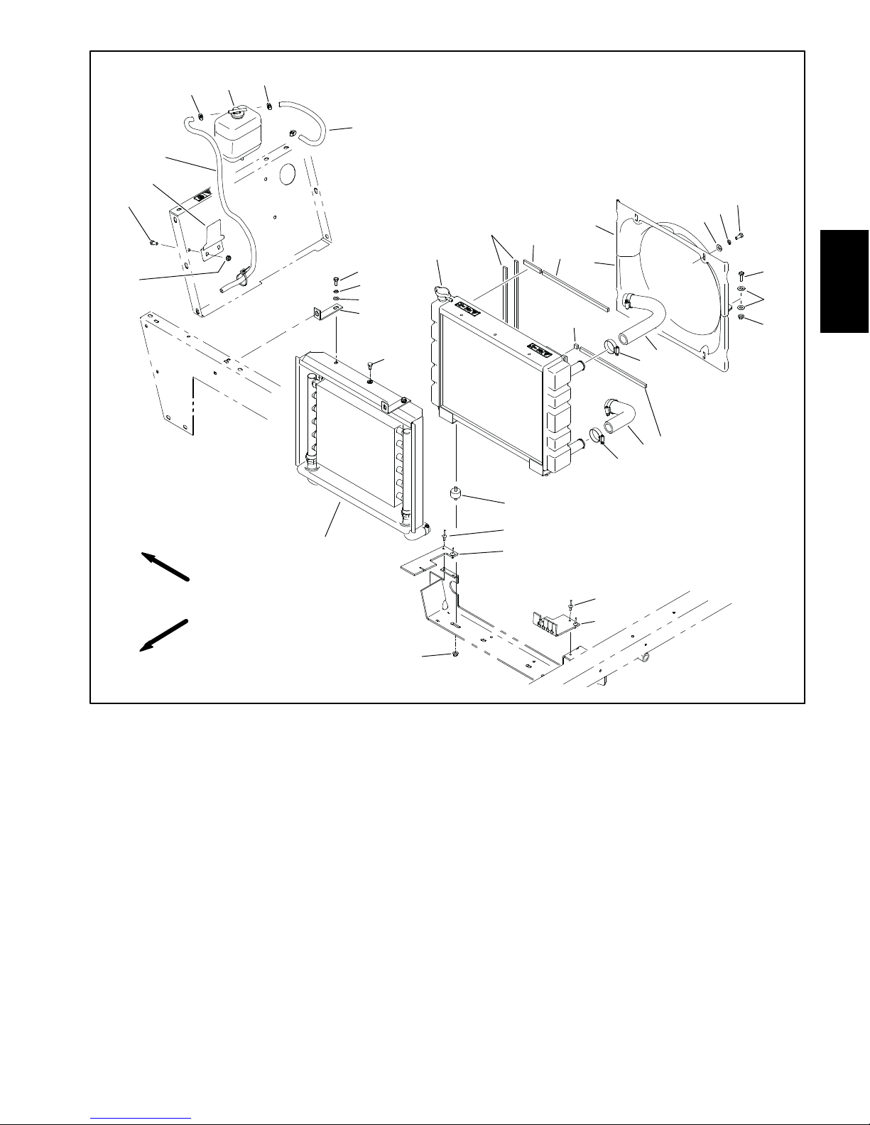
28
27
29
30
31
32
31
33
23
24
25
26
13
12
2
3
1
10
4
9
5
11
14
11
15
Engine
Kubota Diesel
RIGHT
FRONT
1. Radiator
2. Foam seal (4)
3. Foam seal
4. Foam seal (2)
5. Foam seal
6. Hose clamp (4)
7. Upper radiator hose
8. Lower radiator hose
9. Lower fan shroud
10. Upper fan shroud
11. Flat washer (8)
22
21
20
12. Lock washer (4)
13. Cap screw (4)
14. Cap screw (2)
15. Flange nut (2)
16. Iso−mount (2)
17. Pop rivet (4)
18. Heat baffle − RH
19. Heat baffle − LH
20. Flange nut (2)
21. Fan shroud and oil cooler
22. Cap screw (4)
Figure 7
16
17
18
7
6
4
8
6
17
19
23. Cap screw (2)
24. Lock washer (6)
25. Flat washer (6)
26. Bracket (2)
27. Flange nut (2)
28. Cap screw (2)
29. Overflow bottle bracket
30. Hose (vent)
31. Hose clamp (3)
32. Overflow bottle
33. Hose (radiator)
9. Remove four (4) cap screws (Fig. 7 item 13), lock
washers and flat washers that secure fan shroud assembly to radiator.
10.Remove two (2) cap screws (Fig. 7 item 14), flat
washers and flange nuts to separate the fan shroud
halves and carefully remove the upper fan shroud from
the machine.
Multi Pro 5800−D Page 3 − 13 Kubota Diesel Engine
11.Remove six (6) cap screws (Fig. 7 items 22 and 23),
lock washers and flat washers that secure front radiator
shroud and oil cooler (Fig. 7 item 21) to radiator.
12.Remove two (2) flange nuts (Fig. 7 item 20) that secure the iso−mounts on the bottom of the radiator to the
machine frame.
Page 30

13.Carefully lift radiator up and out of the machine.
14.Inspect radiator hoses and rubber iso−mounts. Replace worn or damaged components as necessary.
15.,Inspect foam radiator shroud seals and foam radiator seals in machine frame. Replace any foam seals that
are damaged or deteriorated.
Installation
6. Connect lower and upper radiator hoses to the radiator. Secure hoses with hose clamps.
7. Carefully pivot console assembly back in position
taking care to not damage wire harness or throttle cable.
Install fasteners to secure console assembly to seat box
assembly (Fig. 6).
8. Secure both seat belt bracket assemblies to seat bo x
with carriage screws and flange nuts (Fig. 6).
1. Position lower fan shroud below fan.
2. Carefully lower radiator into the machine. Secure
iso−mounts on the bottom of the radiator to the machine
frame with two (2) flange nuts.
3. Secure radiator to front radiator shroud and oil cooler
(Fig. 7 item 21) with six (6) cap screws (Fig. 7 items 22
and 23), lock washers and flat washers.
4. Secure upper fan shroud to lower fan shroud with
cap screws (Fig. 7 item 14), flat washers and flange
nuts.
5. Secure fan shroud assembly to radiator with four (4)
cap screws (Fig. 7 item13), lock washers and flat washers. Make sure that clearance exists between fan
shrouds and fan at all points before tightening fasteners.
9. Fit overflow hose to radiator flange and secure with
hose clamp. Make sure overflow hose is not kinked.
10.Fill radiator with coolant (see machine Operator ’s
Manual)
11. Check position of electrical wires, hydraulic hoses
and control cables for proper clearance with rotating,
high temperature and moving components.
12.Start engine and check for proper operation. Check
all coolant hose connections for leaks.
13.Install the undercarriage shrouds to the machine
(see Undercarriage Shrouds in Chapter 9 − Chassis in
this manual).
14.Install the seats and hinged seat panels to the seat
box (see Seats in Chapter 9 − Chassis in this manual).
Multi Pro 5800−DPage 3 − 14Kubota Diesel Engine
Page 31

This page is intentionally blank.
Engine
Kubota Diesel
Multi Pro 5800−D Page 3 − 15 Kubota Diesel Engine
Page 32

Engine
11
12
13
1
2
2
5
8
7
12
11
4
3
5
6
7
RIGHT
FRONT
1. Engine assembly
2. Cap screw (4)
3. Lock washer (8)
4. Cap screw (8)
5. Cap screw (8)
6. Rear engine mount bracket (2)
7. Engine mount (4)
8. Front left engine mount
9. Snubbing washer (4)
The following engine removal and installation procedures describe lifting and lowering the engine out from
above the machine.
Removal (Fig. 8)
1. Park machine on a level surface, stop engine, engage parking brake and remove key from the ignition
switch.
2. Disconnect negative (−) and then positive (+) battery
cables from the battery.
3. Remove battery and battery tray from machine.
9
9
10
10
Figure 8
10. Flange nut (12)
11. Cap screw (8)
12. Lock washer (8)
13. Front right engine mount
4. Remove the front fenders.
5. Remove the radiator (see Radiator in this chapter).
6. Detach the air cleaner hose from the R.O.P.S. bar
(see Air Cleaner in this chapter).
7. Loosen the hose clamp at the intake manifold of the
engine and disconnect the air cleaner hose from the engine manifold (see Air Cleaner in this chapter).
8. Remove exhaust system from engine (see Exhaust
System Removal in this chapter).
Multi Pro 5800−DPage 3 − 16Kubota Diesel Engine
Page 33

3
7
6
5
3
4
3
9
4
2
1
10
12
4
3
13
4
8
6
3
11
Engine
Kubota Diesel
1. Access panel
2. Seat base − front
3. Washer head screw (20)
4. Flange nut (20)
5. Seat base − RH
6. Support strap (2)
7. Cross member
8. Engine shroud
9. Cross member support − RH
9. Depending on the type of engine hoist you use, you
may wish to remove the R.O.P .S. bar from the machine.
10.Remove spray tank (see Spray Tank in the Spray
System chapters in this manual).
11.Remove engine shroud from back of seat base
(Fig. 9).
12.Label the wire harness connector at the glow plug
controller attached to the front seat base panel (Fig. 9).
13.Label the wire harness connectors at the relays and
ground terminal block attached to the left side seat base
panel.
14.Remove the fuse block from the mounting bracket on
the left side seat base panel.
Figure 9
10. Cross member support − LH
11. Seat base − LH
12. Glow plug controller
13. Fuse block
15.Remove seat base panels (left side, right side and
front), rear cross member and cross member supports
from machine (Fig. 9).
CAUTION
Hydraulic pump assembly weighs approximately 72 pounds (33 kg). Make sure that pump assembly is well supported (from above or below)
during engine removal.
16.Detach hydraulic pump assembly from engine (see
Piston (Traction) Pump in Chapter 4 − Hydraulic System
in this manual).
Multi Pro 5800−D Page 3 − 17 Kubota Diesel Engine
Page 34

17.Label and disconnect wire harness connectors at the
following locations:
A. Remove positive battery cable and fusible link
connector from st a r t e r m o t o r s o l e n oid stu d ( F i g . 10).
B. Disconnect wire harness connector from starter
motor.
3
1
C. Remove cap screw and lock washer that secure
negative battery cable and wire harness ground wire
to engine block (Fig. 10).
D. Remove wire harness connector from glow plug
terminal (Fig. 11).
E. Disconnect wire harness connector from temperature sender (Fig. 11).
F. Remove cable from alternator stud and disconnect wire harness connector from alternator
(Fig. 12).
G. Disconnect wire harness connector from oil pressure switch.
H. Disconnect wire harness connector from fuel
stop solenoid (Fig. 13).
18.Clamp fuel supply hose after the fuel/water separator to prevent leakage (Fig. 13). Disconnect fuel supply
hose from the fuel injector pump on engine and fuel return hose from the fuel rail. Position disconnected fuel
hoses away from engine.
2
4
Figure 10
1. Starter motor stud
2. Negative battery cable
3. Harness ground wire
4. Fusible link connector
1
2
Figure 11
1. Temperature sender 2. Glow plug terminal
19.Remove throttle cable from injector pump (Fig. 13):
A. Loosen screw that secures cable stop on throttle
cable. Slide cable stop from cable.
B. Loosen cable clamp and remove throttle cable
from under clamp.
C. Slide cable end out of swivel and position throttle
cable away from the engine.
20.Record location of any cable ties used to secure the
wiring harness, fuel lines or hydraulic hoses to the engine assembly. Remove cable ties attached to engine
assembly.
21.Remove flange nuts, snubbing washers and cap
screws securing the engine brackets to engine mounts
(Fig. 8).
2
3
1. Alternator
2. Alternator stud
1
Figure 12
3. Harness connector
Multi Pro 5800−DPage 3 − 18Kubota Diesel Engine
Page 35

CAUTION
2
Make sure that hoist or lift used to remove engine can properly support engine. Engine assembly weighs approximately 275 pounds
(125 kg).
IMPORTANT: Make sure to not damage the engine,
fuel hoses, hydraulic lines, electrical harness or
other parts while removing the engine assembly.
22.Using a hoist and the lifting lugs provided on the engine, carefully lift the engine from the machine.
23.If necessary, remove engine brackets, pump
adapter and flywheel coupler from the engine, or engine
mounts from frame.
Installation (Fig. 8)
1. Park machine on a level surface and engage parking
brake.
2. Make sure that all parts removed from the engine
during maintenance or rebuilding (including engine
mount brackets) are reinstalled to the engine assembly .
3. If engine mounts were removed from frame, secure
mounts to frame with cap screws and flange nuts.
IMPORTANT: Make sure to not damage the engine,
fuel hoses, hydraulic lines, electrical harness or
other parts while installing the engine assembly.
CAUTION
Make sure that hoist or lift used to remove engine can properly support engine. Engine assembly weighs approximately 275 pounds
(125 kg).
4. Using a hoist and the lifting lugs provided on the engine, carefully lift the engine into the machine. Insert cap
screws through engine brackets and motor mounts from
above. Install snubbing washers and flange nuts on cap
screws and tighten (Fig. 8).
1
4
1. Fuel stop solenoid
2. Fuel supply hose
3. Water/fuel filter
5. Connect throttle cable to injector pump (Fig. 13):
A. Position throttle cable to engine.
B. Insert the throttle cable end into the swivel in
speed control lever. Slide cable stop onto cable end
and secure with screw.
C. Position throttle cable under cable clamp.
D. Adjust throttle control cable (see Adjust Throttle
Control Cable in the Adjustments section of this
chapter).
6. Connect fuel supply hose to the fuel injector pump
and fuel return hose to fuel rail on engine (Fig. 13). Remove clamp from fuel hose that was used to prevent
leakage during engine removal.
7. Using labels placed during engine removal, attach all
engine electrical connections (see step 17. in removal
procedure).
8. Install hydraulic pump assembly to engine (see Pis-
ton (Traction) Pump Installation in Chapter 4 − Hydraulic
System in this manual).
9. Install seat base panels (left side, right side and
front), rear cross member and cross member supports
to machine (Fig. 9).
5
6
3
Figure 13
4. Throttle cable
5. Cable clamp
6. Cable stop
Engine
Kubota Diesel
Multi Pro 5800−D Page 3 − 19 Kubota Diesel Engine
Page 36

10.Install fuse block to left side seat base panel.
17.Install the radiator (see Radiator in this chapter).
11. Using labels placed during engine removal, attach
wire harness connections at glow plug controller (front
seat base panel) and relays (left side seat base panel.
12.Install engine shroud to back of seat base (Fig. 9).
13.Install spray tank (see Spray Tank in the Spray S y stem chapters in this manual).
14.If previously removed, install the R.O.P.S. bar to the
machine.
15.Install exhaust system (see Exhaust System Installation in this chapter).
IMPORTANT: Any leaks in the air intake system will
cause serious engine damage. Make sure that all air
cleaner components are in good condition and are
properly secured during assembly.
16.Install air cleaner hoses to engine manifold and
R.O.P.S. bar (see Air Cleaner in this chapter). Make
sure that hose clamps are properly tightened.
18.Install cable ties to secure the wiring harness, fuel
lines and hydraulic hoses to the engine assembly using
notes taken during engine removal.
19.Install the front fenders.
20.Install battery and battery tray to machine.
21.Properly fill the radiator with coolant (see machine
Operator’s Manual).
22.Check engine oil level and adjust if necessary.
23.Connect positive (+) and then negative (−) battery
cables to the battery.
24.Check position of wires, fuel lines, hydraulic hoses
and cables for proper clearance with rotating, high temperature and moving components.
25.Start engine and check for proper operation. Check
all hose connections for leaks. Check engine speed.
Multi Pro 5800−DPage 3 − 20Kubota Diesel Engine
Page 37

This page is intentionally blank.
Engine
Kubota Diesel
Multi Pro 5800−D Page 3 − 21 Kubota Diesel Engine
Page 38

Flywheel Coupler
16
11
RIGHT
FRONT
24356
1
12
13
14
15
78 9
6
1011
Figure 14
1. Coupling
2. Flywheel housing
3. Lock washer (2)
4. Cap screw (2)
5. Plastic plug (2)
6. Cap screw (6)
7. Cap screw (2)
8. Lock washer (8)
9. Cap screw (8)
10. Rear mount bracket (2)
11. Lock washer (9)
Coupler Removal (Fig. 14)
NOTE: The hydraulic pump assembly needs to be re-
moved from engine before coupler can be removed.
1. If engine is in machine, support rear of engine from
below to prevent it from shifting.
A. Remove hydraulic pump assembly (see Piston
(Traction) Pump i n C h a p t e r 5 − H y d r a u l i c S ystem in
this manual).
B. Remove flange nuts, snubbing washers and cap
screws securing the rear engine mount brackets to
engine mounts.
2. Remove flywheel housing and spring coupler from
the engine.
12. Cap screw (6)
13. Lock washer (6)
14. Snubbing washer (2)
15. Flange nut (2)
16. Cap screw (3)
Coupler Installation (Fig. 14)
1. Position spring coupler to engine flywheel and align
mounting holes. Make sure that coupler hub is away
from engine flywheel (Fig. 15).
2. Secure coupler to flywheel with six (6) cap screws
and lock washers. Tighten cap screws in a crossing pattern.
3. If rear mount brackets were removed from flywheel
housing, secure brackets to housing with removed fasteners.
4. Position flywheel housing to engine. Secure flywheel
housing with cap screws and lock washers. Tighten cap
screws in a crossing pattern.
3. If necessary, remove rear mount brackets from flywheel housing.
Multi Pro 5800−DPage 3 − 22Kubota Diesel Engine
Page 39

5. If engine is in machine:
A. Secure rear engine mount brackets to engine
mounts with flange nuts, snubbing washers and cap
screws.
B. Install hydraulic pump assembly (see Piston
(Traction) Pump Installation in Chapter 5 − Hydraulic
System in this manual).
Engine Side
1. Spring coupler
2. Engine flywheel
1
Hydraulic
Pump Side
3
Engine
Kubota Diesel
2
Figure 15
3. Coupler hub
Multi Pro 5800−D Page 3 − 23 Kubota Diesel Engine
Page 40

This page is intentionally blank.
Multi Pro 5800−DPage 3 − 24Kubota Diesel Engine
Page 41

Table of Contents
SPECIFICATIONS 2............................
GENERAL INFORMATION 3.....................
Operator’s Manual 3..........................
Kubota Workshop and Troubleshooting Manuals 3.
Kubota Gasoline Engine 3.....................
Kubota Gasoline Engine Electronic Control
Module (ECM) 4.............................
SERVICE AND REPAIRS 6......................
Fuel System 6................................
Air Cleaner 10................................
Exhaust System 12...........................
Radiator 14..................................
Engine 18....................................
Engine Removal 18..........................
Engine Installation 21........................
Flywheel Coupler 22...........................
Chapter 4
Kubota Gasoline Engine
Engine
Kubota Gasoline
KUBOTA WORKSHOP MANUAL,
GASOLINE ENGINE WG1605−G−E3
KUBOTA DIAGNOSIS MANUAL − ECM SYSTEM,
GASOLINE ENGINE WG1605−G−E3
Multi Pro 5800−G Page 4 − 1 Kubota Gasoline Engine
Page 42

Specifications
Item Description
Make / Designation WG1605−G−E3, Kubota, 4−Cycle, 4 Cylinder,
Bore x Stroke 3.11 in x 3.09 in (79 mm x 78.4 mm)
Total Displacement 93.8 in3 (1537 cc)
Compression Ratio 9.1:1
Ignition Timing 26 degrees BTDC @ 3000 rpm
Ignition System Full Transistor Battery Ignition T ype
Firing Order 1 − 3 − 4 − 2 (numbers start at fan end)
Low Idle (no load) 1000 RPM
High Idle (no load) 3200 RPM
Direction of Rotation Counterclockwise (Viewed from Flywheel)
Spark Plug Type/Gap NGK IFR6F8DN 0.028 to 0.031 in. (0.7 to 0.8 mm)
Fuel Unleaded Gasoline (up to 10% ethanol),
octane rating of 87 or higher ((R+M)/2 rating method)
Water Cooled, Gasoline Engine
Fuel Tank Capacity 12 U.S. gallons (45 liters)
Governor Electronic
Engine Oil API Classification SL or Higher
Oil Pump Trochoid Type
Engine Oil Capacity (approximate) 5.4 U.S. quarts (5.1 liters) with Filter
Cooling System Capacity (approximate − including reserve tank) 5.8 U.S. quarts (5.5 liters)
Starter 12 VDC, 1.0 KW
Alternator/Regulator 12 VDC 60A
Engine Dry Weight (approximate) 262 lbs (119 kg)
(see Operator’s Manual for viscosity recommendations)
Multi Pro 5800−GPage 4 − 2Kubota Gasoline Engine
Page 43

General Information
This Chapter gives information about specifications, adjustments and repair of the Kubota Gasoline engine that
powers the Multi Pro 5800−G.
Operator ’s Manual
The Operator’s Manual provides information regarding
the operation, general maintenance and maintenance
intervals for the Kubota gasoline engine that powers
your Multi Pro 5800−G. Refer to that publication for
additional information when servicing the machine.
Kubota Workshop and Troubleshooting Manuals
General maintenance procedures are described in your
Operator’s Manual. Information on engine testing, disassembly and reassembly is identified in the Kubota
Workshop Manual (WG1605 Series) that is included at
the end of this chapter. Information on engine troubleshooting and testing is identified in the Kubota Diagnosis Manual (WG1605 Series) that is included at the
end of this chapter.
Kubota Gasoline Engine
The engine used in your Multi Pro 5800−G is a Kubota
WG1605 Series gasoline engine. Engine features include an electronic control module (ECM) that controls
a common rail fuel injection system with direct injection,
electronic throttle valve (ETV), an electronic governor
and a catalytic muffler exhaust system with oxygen sensors. The ECM receives information from numerous engine sensors. The information provided allows the
engine ECM to monitor and control engine operation for
optimum engine performance.
Most engine repairs and adjustments require tools
which are commonly available in many service shops.
Special tools are described in the Kubota Workshop
Manual EG1605 Series). The use of some specialized
test equipment is explained. However, the cost of the
test equipment and the specialized nature of some repairs may dictate that the work be done at an engine repair facility.
Engine
Kubota Gasoline
Multi Pro 5800−G Page 4 − 3 Kubota Gasoline Engine
Figure 1
Page 44

Kubota Gasoline Engine Electronic Control Module (ECM)
The Kubota gasoline engine that powers your Multi Pro
5800−G uses an electronic control unit (ECM) for engine
management. All wire harness electrical connectors
should be plugged into the ECM before the machine
ignition switch is moved from the OFF position to either
the ON or START position.
1
The engine electrical components (e.g. ECM, O2
sensor, throttle control, power relay, ETV relay) are
identified and matched in the engine ECM program. If
engine electrical components are replaced on the engine, the Kubota electronic tool must be used to update
the ECM program which will ensure correct engine operation.
If the engine ECM identifies that an engine problem exists, an engine fault may appear on the InfoCenter Display. In addition, the engine speed may be reduced or
the engine might stop. The Kubota Gasoline Service
Tool (KGST) and software, and the Kubota Diagnosis
Manual − ECM System should be used to provide assistance in identifying the cause of the problem and any
repairs that are necessary . Contact your Toro distributor
for assistance in Kubota engine troubleshooting.
IMPORTANT: Do not plug or unplug the engine
ECM for a period of thirty (30) seconds after the machine key switch is turned OFF. The ECM may remain energized even though the ignition switch is
OFF.
If the engine ECM is to be disconnected for any reason,
make sure that the ignition switch is in the OFF position
with the key removed before disconnecting the engine
ECM. Also, to prevent possible ECM damage when
welding on the machine, disconnect and remove the engine ECM from the machine before welding.
2
Figure 2
1. Gasoline engine
2. Engine ECM
Multi Pro 5800−GPage 4 − 4Kubota Gasoline Engine
Page 45

This page is intentionally blank.
Engine
Kubota Gasoline
Multi Pro 5800−G Page 4 − 5 Kubota Gasoline Engine
Page 46

Service and Repairs
Fuel System
13
14
15
10 to 12 in−lb
(1 N−m)
13 to 65 in−lb
(1 to 7 N−m)
RIGHT
FRONT
10
12
11
16
17
TO
FUEL
RAIL
18
17
9
6
5
8
7
6
4
1
2
25 in−lb (3 N−m)
1. Fuel tank
2. Base
3. Flange nut (2)
4. Carriage bolt (2)
5. Rubber bumper (2)
6. Flat washer (6)
3
Figure 3
7. Flange nut (2)
8. Clamp (2)
9. Cap screw (2)
10. Fuel fill cap
11. Gasket
12. Fuel pump/level sender
13. Flange head screw (4)
14. Tank cover
15. Fuel pump/level sender cap
16. Barb fitting (2)
17. Hose clamp (2)
18. Fuel hose − supply
Multi Pro 5800−GPage 4 − 6Kubota Gasoline Engine
Page 47

DANGER
4
3
UNLOCKED
Because gasoline is highly flammable, use caution when storing or handling it. Do not smoke
while filling the fuel tank. Do not fill fuel tank
while engine is running, hot or when machine is
in an enclosed area. Always fill fuel tank outside
and wipe up any spilled fuel before starting the
engine. Store fuel in a clean, safety−approved
container and keep cap in place. Use diesel fuel
for the engine only; not for any other purpose.
Check Fuel Lines and Connections
Check fuel lines and connections periodically as recommended in the Operator’s Manual. Check lines for deterioration, damage, leaks or loose connections. Replace
hoses, clamps and connections as necessary.
Empty and Clean Fuel Tank
Empty and clean the fuel tank if the fuel system becomes contaminated or if the machine is to be stored for
an extended period.
To clean fuel tank, flush tank out with clean solvent.
Make sure tank is free of contaminates and debris.
1
4
2
LOCKED
1
Engine
Kubota Gasoline
Fuel Tank Removal (Fig. 3)
1. Park machine on a level surface, stop engine, en-
gage parking brake and remove key from the ignition
switch.
2. Use a fuel transfer pump to remove fuel from the fuel
tank and into a suitable container.
3. Remove the fuel tank cover.
4. Disconnect the fuel pump/level sender form the ma-
chine wire harness (2 connectors).
CAUTION
Fuel in supply line may be under pressure. Cover supply hose barb fitting with rag while disconnecting to absorb any fuel leakage.
5. Disconnect the fuel supply hose from the fuel pump/
level sender.
A. Lift supply hose barb fitting lock up to unlock
fitting (Fig. 4).
B. Press barb fitting tab and pull fitting from fuel
pump/level sender.
Figure 4
1. Fuel pump/level sender
fitting
2. Barb fitting lock
(locked − down)
3. Barb fitting lock
(unlocked − up)
4. Barb fitting tab
6. Remove two (2) fuel tank clamps from base and remove fuel tank from machine. Check condition of fuel
tank rubber bumpers and replace if worn or damaged.
7. If necessary, remove fuel pump/level sender from
tank. Check condition of gasket and replace if worn or
damaged. See Fuel Pump/Level Sender in Chapter − 6
Electrical System for testing information. Check and replace fuel filter at fuel pump/level sender pickup as necessary (see machine Operator’s Manual).
8. If necessary, remove fuel hose from machine.
Record fuel hose routing for assembly purposes.
Fuel Tank Installation (Fig. 3)
1. If fuel hose were removed from machine, route fuel
hose through machine as recorded during removal.
Make sure that clearance exists between fuel hose and
machine components along full length of hoses.
2. Secure fuel tank to machine with two (2) clamps at
base. Tighten clamp fasteners to 25 in−lbs (3 N−m).
Multi Pro 5800−G Page 4 − 7 Kubota Gasoline Engine
Page 48

3. Install fuel pump/level sender if previously removed
from tank. Tighten fuel pump/level sender cap from 13
to 65 in−lbs (1 to 7 N−m).
4. Connect fuel hose to top of fuel tank.
5. Connect machine wire harness to fuel pump/level
sender (2 connectors)
6. Install fuel tank cover and tighten cover screws from
10 to 12 in−lbs (1 N−m).
A. Push supply hose barb fitting onto fuel pump/level sender until an audible “Click” is heard.
B. Press barb fitting lock down to lock fitting in place
(Fig. 4).
7. Fill fuel tank. Start engine and check fuel line connections for leaks.
Multi Pro 5800−GPage 4 − 8Kubota Gasoline Engine
Page 49

This page is intentionally blank.
Engine
Kubota Gasoline
Multi Pro 5800−G Page 4 − 9 Kubota Gasoline Engine
Page 50

Air Cleaner
1
2
5
6
3
4
7
15
14
9
13
16
8
17
18
9
RIGHT
FRONT
1. Cap
2. Hose clamp
3. Flange head screw
4. Clamp
5. Flange nut (2)
6. Bracket
7. Flange nut
9
19
10
11
12
9
Figure 5
8. Hose
9. Hose clamp (5)
10. Flange head screw (2)
11. Air cleaner mount
12. Flange nut (2)
13. Hose
17
14. Air cleaner assembly
15. U−Bolt
16. Breather hose
17. Hose clamp (2)
18. Tee
19. Hose
Multi Pro 5800−GPage 4 − 10Kubota Gasoline Engine
Page 51

Removal (Fig. 5)
NOTE: For air cleaner maintenance information, see
the machine Operator’s Manual.
1. Raise passenger seat to access air cleaner assembly.
2. Remove air cleaner components as needed.
Installation (Fig. 5)
IMPORTANT: Any leaks in the air filter system will
cause serious engine damage. Make sure that all air
cleaner components are in good condition and are
properly secured during installation.
2
1
4
3
1. Assemble air cleaner system. Make sure that vacuator valve on air cleaner cover points downward after assembly (Fig. 6).
1. Air cleaner housing
2. Air cleaner element
Figure 6
3. Air cleaner cover
4. Vacuator valve
Engine
Kubota Gasoline
Multi Pro 5800−G Page 4 − 11 Kubota Gasoline Engine
Page 52

Exhaust System
RIGHT
FRONT
18
19
17
16
20
16
17
8
9
6
7
10
APPLY ANTI SIEZE
LUBRICANT
16
15
34
32
1
32
33
APPLY
LOCTITE 242
5
4
3
2
7
26
13
29 to 44 ft−lb
(40 to 60 N−m)
29
31
6
28
7
14
13
25
24
11
12
21
22
23
24
3
3
27
26
5
7
3
30
1. Gasket
2. Header pipe
3. Flange head screw (16)
4. Shield − composite
5. Muffler shield − outer (2)
6. Cap screw (4)
7. Lock washer (4)
8. Flange head screw (2)
9. Flat washer (2)
10. Bracket − catalyst
11. Cap screw (2)
12. Gasket
Figure 7
13. Oxygen sensor (2)
14. Tail pipe
15. Hanger
16. Flange nut (2)
17. Flat washer (2)
18. Flange nut
19. Rubber hanger
20. Cap screw
21. Flange nut (2)
22. Lock washer (2)
23. Flat washer (2)
24. Muffler shield − inner (2)
25. Catalytic muffler
26. Flange nut (8)
27. Gasket
28. Cap screw (4)
29. Hose clamp
30. Jacket lower
31. Jacket upper
32. Flange head screw (2)
33. Flange head screw
34. Manifold shield − bottom
Multi Pro 5800−GPage 4 − 12Kubota Gasoline Engine
Page 53

Installation (Fig. 7)
CAUTION
The muffler and exhaust system may be hot. To
avoid possible burns, allow the engine and exhaust system to cool before working on the exhaust system.
Removal (Fig. 7)
1. Park machine on a level surface, stop engine, engage parking brake and remove key from the ignition
switch.
2. Remove the rear undercarriage shroud from the machine (see Undercarriage Shrouds in Chapter 9 − Chassis in this manual).
3. Disconnect rear oxygen sensor from machine wire
harness and remove tail pipe.
4. Remove catalytic muffler outer and inner heat
shields.
5. Disconnect catalytic muffler from header pipe and
machine frame and remove muffler.
6. Disconnect front oxygen sensor from machine wire
harness and remove header pipe.
7. Locate and discard exhaust system gaskets. Clean
gasket surfaces on engine exhaust manifold, catalytic
muffler and tail pipe.
8. Replace damaged or worn header pipe jackets or
shield if necessary.
NOTE: New oxygen sensor threads come pre−coated
with an anti seize compound. If a previously installed
oxygen sensor is used, apply a small amount of anti−
seize to the threads.
1. If installing an oxygen sensor, do not allow the tip of
the sensor to touch anything as it may become contaminated. Tighten from 29 to 44 ft−lb (40 to 60 N−m).
2. If header pipe was removed from engine, use a new
gasket and install header pipe and fasteners finger tight.
3. If catalyst muffler was removed, use a new gasket
and install muffler and fasteners finger tight.
4. If tail pipe was removed from engine, use a new gasket and install pipe pipe, hanger and fasteners finger
tight.
5. Tighten exhaust system components i n the following
order:
A. Tighten fasteners securing header pipe to exhaust header.
B. Tighten fasteners securing catalyst muffler to
header pipe and to machine frame.
C. Tighten fasteners securing tailpipe to catalyst
muffler.
D. Position the tailpipe so the outlet is parallel to the
ground and tighten exhaust system hanger and
bracket fasteners..
6. Install catalytic muffler inner and outer heat shields.
Engine
Kubota Gasoline
7. Install the rear undercarriage shroud to the machine
(see Undercarriage Shrouds in Chapter 9 − Chassis in
this manual).
Multi Pro 5800−G Page 4 − 13 Kubota Gasoline Engine
Page 54

Radiator
3
1
5
6
1. Console assembly
2. Seat belt bracket assembly (2)
Figure 8
3. Carriage screw (12)
4. Flange nut (16)
2
3
5
4
4
5. Flange head screw (4)
6. Radiator
2
4
Removal
1. Park machine on a level surface, stop engine, engage parking brake and remove key from the ignition
switch.
2. Remove the seats and hinged seat panels from the
seat box (see Seats in Chapter 9 − Chassis in this manual).
3. Remove the undercarriage shrouds from the machine (see Undercarriage Shrouds in Chapter 9 − Chassis in this manual).
CAUTION
Do not open radiator cap or drain coolant if the
radiator or engine is hot. Pressurized, hot coolant can escape and cause burns. Ethylene−glycol antifreeze is poisonous. Dispose of coolant
properly or store it in a properly labeled container away from children and pets.
4. Drain coolant from radiator (see machine Operator’s
Manual). The coolant drain valve is located under the
passenger seat, in the lower right corner of the radiator .
5. Loosen hose clamps that secure the upper and lower
radiator hoses to the radiator and disconnect the hoses
from the radiator.
6. Loosen hos e clamp that secures overflow hose to radiator cap flange. Remove overflow hose from radiator.
7. Remove carriage screws and flange nuts that secure
seat belt bracket assemblies to seat box and remove
both bracket assemblies from machine (Fig.8).
8. Remove fasteners that secure console assembly to
seat box (Fig. 8). Carefully pivot console assembly rearward and to the right to allow radiator access. Take care
to not damage the wire harness or throttle cable. Support console to prevent it from shifting, falling, or hanging from wire harness or throttle cable.
Multi Pro 5800−GPage 4 − 14Kubota Gasoline Engine
Page 55

28
27
29
30
31
32
31
33
23
24
25
26
13
12
2
3
1
10
4
9
11
14
11
5
15
RIGHT
FRONT
1. Radiator
2. Foam seal (4)
3. Foam seal
4. Foam seal (2)
5. Foam seal
6. Hose clamp (4)
7. Upper radiator hose
8. Lower radiator hose
9. Lower fan shroud
10. Upper fan shroud
11. Flat washer (8)
22
21
20
12. Lock washer (4)
13. Cap screw (4)
14. Cap screw (2)
15. Flange nut (2)
16. Iso−mount (2)
17. Pop rivet (4)
18. Heat baffle − RH
19. Heat baffle − LH
20. Flange nut (2)
21. Fan shroud and oil cooler
22. Cap screw (4)
Figure 9
16
17
18
7
6
4
8
6
17
19
23. Cap screw (2)
24. Lock washer (6)
25. Flat washer (6)
26. Bracket (2)
27. Flange nut (2)
28. Cap screw (2)
29. Overflow bottle bracket
30. Hose (vent)
31. Hose clamp (3)
32. Overflow bottle
33. Hose (radiator)
Engine
Kubota Gasoline
9. Remove four (4) cap screws (Fig. 9 item 13), lock
washers and flat washers that secure fan shroud assembly to radiator.
10.Remove two (2) cap screws (Fig. 9 item 14), flat
washers and flange nuts to separate the fan shroud
halves and carefully remove the upper fan shroud from
the machine.
Multi Pro 5800−G Page 4 − 15 Kubota Gasoline Engine
11.Remove six (6) cap screws (Fig. 9 items 22 and 23),
lock washers and flat washers that secure front radiator
shroud and oil cooler (Fig. 7 item 21) to radiator.
12.Remove two (2) flange nuts (Fig. 9 item 20) that secure the iso−mounts on the bottom of the radiator to the
machine frame.
Page 56

13.Carefully lift radiator up and out of the machine.
14.Inspect radiator hoses and rubber iso−mounts. Replace worn or damaged components as necessary.
15.,Inspect foam radiator shroud seals and foam radiator seals in machine frame. Replace any foam seals that
are damaged or deteriorated.
Installation
6. Connect lower and upper radiator hoses to the radiator. Secure hoses with hose clamps.
7. Carefully pivot console assembly back in position
taking care to not damage wire harness or throttle cable.
Install fasteners to secure console assembly to seat box
assembly (Fig. 8).
8. Secure both seat belt bracket assemblies to seat bo x
with carriage screws and flange nuts (Fig. 8).
1. Position lower fan shroud below fan.
2. Carefully lower radiator into the machine. Secure
iso−mounts on the bottom of the radiator to the machine
frame with two (2) flange nuts.
3. Secure radiator to front radiator shroud and oil cooler
(Fig. 9 item 21) with six (6) cap screws (Fig. 9 items 22
and 23), lock washers and flat washers.
4. Secure upper fan shroud to lower fan shroud with
cap screws (Fig. 9 item 14), flat washers and flange
nuts.
5. Secure fan shroud assembly to radiator with four (4)
cap screws (Fig. 9 item13), lock washers and flat washers. Make sure that clearance exists between fan
shrouds and fan at all points before tightening fasteners.
9. Fit overflow hose to radiator flange and secure with
hose clamp. Make sure overflow hose is not kinked.
10.Fill radiator with coolant (see machine Operator ’s
Manual)
11. Check position of electrical wires, hydraulic hoses
and control cables for proper clearance with rotating,
high temperature and moving components.
12.Start engine and check for proper operation. Check
all coolant hose connections for leaks.
13.Install the undercarriage shrouds to the machine
(see Undercarriage Shrouds in Chapter 9 − Chassis in
this manual).
14.Install the seats and hinged seat panels to the seat
box (see Seats in Chapter 9 − Chassis in this manual).
Multi Pro 5800−GPage 4 − 16Kubota Gasoline Engine
Page 57

This page is intentionally blank.
Engine
Kubota Gasoline
Multi Pro 5800−G Page 4 − 17 Kubota Gasoline Engine
Page 58

Engine
1
11
12
13
1
2
2
5
8
7
12
11
4
3
5
6
7
RIGHT
FRONT
1. Engine assembly
2. Cap screw (4)
3. Lock washer (8)
4. Cap screw (8)
5. Cap screw (8)
6. Rear engine mount bracket (2)
7. Engine mount (4)
8. Front left engine mount
9. Snubbing washer (4)
The following engine removal and installation procedures describe lifting and lowering the engine out from
above the machine.
Removal
1. Park machine on a level surface, stop engine, engage parking brake and remove key from the ignition
switch.
2. Disconnect negative (−) and then positive (+) battery
cables from the battery.
9
9
10
10
Figure 10
10. Flange nut (12)
11. Cap screw (8)
12. Lock washer (8)
13. Front right engine mount
3. Remove battery and battery tray from machine.
4. Remove the front fenders.
5. Remove the radiator (see Radiator in this chapter).
6. Detach the air cleaner hose from the R.O.P.S. bar
(see Air Cleaner in this chapter).
7. Loosen the hose clamp at the intake manifold of the
engine and disconnect the air cleaner hose from the engine manifold (see Air Cleaner in this chapter).
Multi Pro 5800−GPage 4 − 18Kubota Gasoline Engine
Page 59

3
6
5
7
3
8
4
3
2
1
1. Access panel
2. Seat base − front
3. Washer head screw (20)
4. Flange nut (20)
9
4
10
4
3
Figure 11
5. Seat base − RH
6. Support strap (2)
7. Cross member
8. Engine shroud
12
3
6
4
3
11
Engine
Kubota Gasoline
9. Cross member support − RH
10. Cross member support − LH
11. Seat base − LH
12. Fuse block
8. Disconnect the breather hose from the engine valve
cover.
15.Remove seat base panels (left side, right side and
front), rear cross member and cross member supports
from machine (Fig. 11).
9. Remove exhaust system from engine (see Exhaust
System Removal in this chapter).
10.Depending on the type of engine hoist you use, you
CAUTION
may wish to remove the R.O.P .S. bar from the machine.
Hydraulic pump assembly weighs approximate-
11. Remove spray tank (see Spray Tank in the Spray
System chapters in this manual).
12.Remove engine shroud from back of seat base
ly 72 pounds (33 kg). Make sure that pump assembly is well supported (from above or below)
during engine removal.
(Fig. 11).
16.Detach hydraulic pump assembly from engine (see
13.Label the wire harness connectors at the relays and
ground terminal block attached to the left side seat base
Piston (Traction) Pump in Chapter 4 − Hydraulic System
in this manual).
panel.
NOTE: Separate the Yanmar engine wire harness from
14.Remove the fuse block from the mounting bracket on
the left side seat base panel.
the machine wire harness and remove the engine with
the Y anmar engine wire harness connected to the individual engine electrical components.
Multi Pro 5800−G Page 4 − 19 Kubota Gasoline Engine
Page 60

17.Label and disconnect wire harness connectors at the
following locations:
A. Remove positive battery cable and wire harness
connector from starter motor (Fig. 12).
B. Remove cap screw and lock washer that secure
negative battery cable and wire harness ground wire
to engine block (Fig. 12).
3
1
C. Disconnect the 16 pin interconnect between the
Yanmar engine wire harness and the machine wire
harness. The interconnect is located on the right side
of engine near the engine power center (Fig. 13).
18.Clamp fuel supply hose near the engine fuel rail to
prevent leakage (see Fuel System in this chapter). Disconnect fuel supply hose from the fuel rail and position
disconnected fuel hose away from engine.
19.Record location of any cable ties used to secure the
wiring harness, fuel line or hydraulic hoses to the engine
assembly. Remove cable ties attached to engine assembly.
20.Remove flange nuts, snubbing washers and cap
screws securing the engine brackets to engine mounts.
CAUTION
Make sure that hoist or lift used to remove engine can properly support engine. Engine assembly weighs approximately 295 pounds
(134 kg).
1. Starter motor stud
2. Negative battery cable
2
Figure 12
3. Harness ground wire
1
2
IMPORTANT: Make sure to not damage the engine,
fuel hoses, hydraulic lines, electrical harness or
other parts while removing the engine assembly.
21.Using a hoist and the lifting lugs provided on the engine, carefully lift the engine from the machine.
22.If necessary, remove engine brackets, pump
adapter and flywheel coupler from the engine, or engine
mounts from frame.
Figure 13
1. Engine power center 2. 16 pin interconnect
Multi Pro 5800−GPage 4 − 20Kubota Gasoline Engine
Page 61

Installation
1. Park machine on a level surface and engage parking
brake.
2. Make sure that all parts removed from the engine
during maintenance or rebuilding (including engine
mount brackets, pump adapter and flywheel coupler)
are reinstalled to the engine assembly.
IMPORTANT: Make sure to not damage the engine,
fuel hoses, hydraulic lines, electrical harness or
other parts while installing the engine assembly.
9. Using labels placed during engine removal, attach
wire harness connections at glow plug controller (front
seat base panel) and relays (left side seat base panel.
10.Install engine shroud to back of seat base (Fig. 11).
11.Install spray tank (see Spray Tank in the Spray S ys tem chapters in this manual).
12.If previously removed, install the R.O.P.S. bar to the
machine.
13.Install exhaust system (see Exhaust System Installation in this chapter).
CAUTION
Make sure that hoist or lift used to remove engine can properly support engine. Engine assembly weighs approximately 295 pounds
(134 kg).
3. Using a hoist and the lifting lugs provided on the engine, carefully lift the engine into the machine. Insert cap
screws through engine brackets and motor mounts from
above. Install snubbing washers and flange nuts on cap
screws and tighten (Fig. 10).
4. Connect fuel supply hose to the engine fuel rail. Remove clamp from fuel hose that was used to prevent
leakage during engine removal.
5. Using labels placed during engine removal, attach all
engine electrical connections (see step 17. in removal
procedure).
6. Install hydraulic pump assembly to engine (see Piston (Traction) Pump Installation in Chapter 4 − Hydraulic
System in this manual).
7. Install seat base panels (left side, right side and
front), rear cross member and cross member supports
to machine (Fig. 11).
8. Install fuse block to left side seat base panel.
IMPORTANT: Any leaks in the air intake system will
cause serious engine damage. Make sure that all air
cleaner components are in good condition and are
properly secured during assembly.
14.Install air cleaner hoses to engine manifold and
R.O.P.S. bar (see Air Cleaner in this chapter). Make
sure that hose clamps are properly tightened.
15.Install the radiator (see Radiator in this chapter).
16.Install cable ties to secure the wiring harness, fuel
lines and hydraulic hoses to the engine assembly using
notes taken during engine removal.
17.Install the front fenders.
18.Install battery and battery tray to machine.
19.Properly fill the radiator with coolant (see machine
Operator’s Manual).
20.Check engine oil level and adjust if necessary.
21.Connect positive (+) and then negative (−) battery
cables to the battery.
22.Check position of wires, fuel lines, hydraulic hoses
and cables for proper clearance with rotating, high temperature and moving components.
23.Start engine and check for proper operation. Check
all hose connections for leaks. Check engine speed.
Engine
Kubota Gasoline
Multi Pro 5800−G Page 4 − 21 Kubota Gasoline Engine
Page 62

Flywheel Coupler
RIGHT
FRONT
11
16
1. Coupling
2. Flywheel housing
3. Lock washer (2)
4. Cap screw (2)
5. Plastic plug (2)
6. Cap screw (6)
1
Figure 14
7. Cap screw (2)
8. Lock washer (8)
9. Cap screw (8)
10. Rear mount bracket (2)
11. Lock washer (9)
24356
12
13
14
15
12. Cap screw (6)
13. Lock washer (6)
14. Snubbing washer (2)
15. Flange nut (2)
16. Cap screw (3)
78 9
6
1011
Coupler Removal (Fig. 14)
NOTE: The hydraulic pump assembly needs to be re-
moved from engine before coupler can be removed.
1. If engine is in machine, support rear of engine from
below to prevent it from shifting.
A. Remove hydraulic pump assembly (see Piston
(Traction) Pump i n C h a p t e r 5 − H y d r a u l i c S ystem in
this manual).
B. Remove flange nuts, snubbing washers and cap
screws securing the rear engine mount brackets to
engine mounts.
2. Remove flywheel housing and spring coupler from
the engine.
3. If necessary, remove rear mount brackets from flywheel housing.
Coupler Installation (Fig. 14)
1. Position spring coupler to engine flywheel and align
mounting holes. Make sure that coupler hub is away
from engine flywheel (Fig. 15).
2. Secure coupler to flywheel with six (6) cap screws
and lock washers. Tighten cap screws in a crossing pattern.
3. If rear mount brackets were removed from flywheel
housing, secure brackets to housing with removed fasteners.
4. Position flywheel housing to engine. Secure flywheel
housing with cap screws and lock washers. Tighten cap
screws in a crossing pattern.
Multi Pro 5800−GPage 4 − 22Kubota Gasoline Engine
Page 63

5. If engine is in machine:
A. Secure rear engine mount brackets to engine
mounts with flange nuts, snubbing washers and cap
screws.
B. Install hydraulic pump assembly (see Piston
(Traction) Pump Installation in Chapter X − Hydraulic
System in this manual).
Engine Side
1. Spring coupler
2. Engine flywheel
Figure 15
3. Coupler hub
1
Hydraulic
Pump Side
3
2
Engine
Kubota Gasoline
Multi Pro 5800−G Page 4 − 23 Kubota Gasoline Engine
Page 64

This page is intentionally blank.
Multi Pro 5800−GPage 4 − 24Kubota Gasoline Engine
Page 65

Table of Contents
Chapter 5
Hydraulic System
SPECIFICATIONS 3............................
GENERAL INFORMATION 4.....................
Operator’s Manual 4..........................
Traction Circuit Component Failure 4............
Hydraulic Hoses 5............................
Hydraulic Hose and Tube Installation 6..........
Hydraulic Fitting Installation 7..................
HYDRAULIC SCHEMATIC 9.....................
HYDRAULIC FLOW CIRCUITS 10................
Traction Circuit 10............................
Steering Circuit 12............................
Spray Pump Drive Circuit 14...................
Spray Boom Lift Circuit 16.....................
SPECIAL TOOLS 18............................
TROUBLESHOOTING 22........................
TESTING 26...................................
Traction Circuit
Charge Pressure Test 28....................
Charge Pump Flow Test 30..................
Wheel Motor Efficiency Test 32...............
Traction (Piston) Pump Flow and
Relief Pressure Test 36....................
Steering/Boom Lift Circuit
Gear Pump P2 Flow and Circuit Relief
Pressure Test (Using Tester with Flow
Meter and Pressure Gauge) 40.............
Steering Control Valve and Steering
Cylinder Test 44..........................
Boom Lift Cylinder Internal Leakage Test 46....
Spray Pump Circuit
Gear Pump P1 Flow Test (Using Tester with
Flow Meter and Pressure Gauge) 48........
ADJUSTMENTS 50.............................
Adjust Traction Pedal for Neutral 50.............
SERVICE AND REPAIRS 51.....................
General Precautions for Removing and
Installing Hydraulic System Components 51......
Check Hydraulic Lines and Hoses 51............
Priming Hydraulic Pumps 52...................
Flush Hydraulic System 53.....................
Filtering Closed- Loop Traction Circuit 54........
Charging Hydraulic System 55..................
Gear Pump 56................................
Gear Pump Service 58........................
Piston (Traction) Pump 62.....................
Piston (Traction) Pump Service 66..............
Wheel Motors 68.............................
Wheel Motor Service 70.......................
Spray Pump Drive Motor and Control
Manifold Assembly 72........................
Spray Pump Drive Motor Service 74.............
Spray Pump Control Manifold Service 76........
Steering Control Valve 78......................
Steering Control Valve Service 80...............
Steering Cylinder 82..........................
Steering Cylinder Service 84......
Boom Lift Manifold 86.........................
Boom Lift Manifold Service 88..................
Boom Lift Cylinders 90........................
Boom Lift Cylinder Service 92..................
Oil Cooler 94.................................
Hydraulic Reservoir 96........................
EATON MODEL 72400 SERVO CONTROLLED
PISTON PUMP REPAIR INFORMATION
EATON MODEL 74318 and 74348 PISTON MOTORS:
FIXED DISPLACEMENT, VALVE PLATE DESIGN
REPAIR INFORMATION
TM
PARKER TORQLINK
SAUER/DANFOSS STEERING UNIT TYPE OSPM
SERVICE MANUAL
SERVICE PROCEDURE
.............
System
Hydraulic
Multi Pro 5800 Hydraulic SystemPage 5 - 1
Page 66

This page is intentionally blank.
Multi Pro 5800Hydraulic System Page 5 − 2
Page 67

Specifications
Item Description
Piston (Traction) Pump Variable displacement piston pump (Eaton model 72400)
Maximum Displacement (per revolution) 2.48 in
System Relief Pressure: Forward 4000 PSI (276 bar)
System Relief Pressure: Reverse 4000 PSI (276 bar)
Charge Pump Positive displacement gear type pump
(integral in piston (traction) pump)
Displacement (per revolution) 0.42 in
Charge Pressure 250 to 300 PSI (17 to 21 bar)
Gear Pump 2 section, positive displacement gear type pump
Front section (spray pump drive) displacement (per revolution) 0.95 in
Rear section (steering/boom lift) displacement (per revolution) 0.34 in
Rear Wheel Motors Fixed displacement piston motor (Eaton model 74318)
Displacement (per revolution) 2.48 in
Spray Pump Motor Orbital rotor motor (Parker series TE)
Displacement (per revolution) 6.0 in
Spray Pump Circuit Relief Pressure 2000 PSI (138 bar)
Steering Control Valve Rotary valve steering unit with power beyond
(Sauer Danfoss series OSPM)
Displacement (per revolution) 4.3 in
Steering/Boom Lift Circuit Relief Pressure 1015 PSI (69 bar)
3
(40.6 cc)
3
(6.9 cc)
3
(15.6 cc)
3
(5.6 cc)
3
(40.6 cc)
3
(100 cc)
3
(70 cc)
System
Hydraulic
Hydraulic Filter Spin−on cartridge type
In−line Suction Strainer 100 mesh (in reservoir)
Hydraulic Reservoir Capacity 14 U.S. gal (53 l)
Hydraulic Oil See Operator’s Manual
Multi Pro 5800 Hydraulic SystemPage 5 − 3
Page 68

General Information
Operator’s Manual
The Operator’s Manual provides information regarding
the operation, general maintenance and maintenance
intervals for your Multi Pro machine. Refer to that publication for additional information when servicing the machine.
Traction Circuit Component Failure
The traction circuit on Multi Pro 5800 machines is a
closed loop system that includes the piston (traction)
pump and two (2) rear wheel motors. If a component in
the traction circuit should fail, debris and contamination
from the failed component will circulate throughout the
traction circuit. This contamination can damage other
components in the circuit so it must be removed to prevent additional component failure.
The recommended method of removing traction circuit
contamination would be to temporarily install the Toro
high flow hydraulic filter (see Special Tools in this chapter) into the circuit. This filter should be used when connecting hydraulic test gauges in order to test traction
circuit components or after replacing a failed traction circuit component (e.g. traction (piston) pump or wheel
motor). The filter will ensure that contaminates are removed from the closed loop and thus, do not cause additional component damage.
Once the Toro high flow hydraulic filter kit has been
placed in the circuit, raise and support the machine with
all wheels off the ground. Then, operate the traction circuit to allow oil flow throughout the circuit. The filter will
remove contamination from the traction circuit during
operation. Because the Toro high flow filter is bi−directional, the traction circuit can be operated in both the forward and reverse direction. The filter should be
removed from the machine after contamination has
been removed from the traction circuit. See Filtering
Closed−Loop T raction Circuit in the Service and Repairs
section of this chapter for additional information on using the Toro high flow hydraulic filter.
The alternative to using the Toro high flow hydraulic filter
kit after a traction circuit component failure would be to
disassemble, drain and thoroughly clean all components, tubes and hoses in the traction circuit. If any debris remains in the traction circuit and the machine is
operated, the debris can cause additional circuit component failure.
Multi Pro 5800Hydraulic System Page 5 − 4
Page 69

Hydraulic Hoses
r
r
-
r
Hydraulic hoses are subject to extreme conditions such
as pressure differentials during operation and exposure
to weather, sun, chemicals, very warm storage conditions or mishandling during operation and maintenance.
These conditions can cause hose damage and deterioration. Some hoses are more susceptible to these
conditions than others. Inspect all machine hydraulic
hoses frequently for signs of deterioration or damage:
WARNING
Before disconnecting or performing any work on
hydraulic system, relieve all pressure in system
(see Relieving Hydraulic System Pressure in this
section).
Hard, cracked, cut, abraded, charred, leaking or
otherwise damaged hose.
Kinked, crushed, flattened or twisted hose.
Blistered, soft, degraded or loose hose cover.
Cracked, damaged or badly corroded hose fittings.
When replacing a hydraulic hose, be sure that the hose
is straight (not twisted) before tightening the fittings.
This can be done by observing the imprint (lay−line) on
the hose. Use two wrenches when tightening a hose;
hold the hose straight with one wrench and tighten the
hose swivel nut onto the fitting with the second wrench
(see Hydraulic Hose and Tube Installation in this section). If the hose has an elbow at one end, tighten the
swivel nut on that end before tightening the nut on the
straight end of the hose.
For additional hydraulic hose information, refer to Toro
Service Training Book, Hydraulic Hose Servicing (Part
Number 94813SL).
Keep body and hands away from pin hole leaks o
nozzles that eject hydraulic fluid under high
pressure. Use paper or cardboard, not hands, to
search for leaks. Hydraulic fluid escaping unde
pressure can have sufficient force to penetrate
the skin and cause serious injury. If fluid is in
jected into the skin, it must be surgically re
moved within a few hours by a doctor familia
with this type of injury. Gangrene may result from
such an injury.
System
Hydraulic
Multi Pro 5800 Hydraulic SystemPage 5 − 5
Page 70

Hydraulic Hose and Tube Installation (O−Ring Face Seal Fitting)
1. Make sure threads and sealing surfaces of the hose/
tube and the fitting are free of burrs, nicks, scratches or
any foreign material.
2. As a preventative measure against leakage, it is recommended that the face seal O−ring be replaced any
time the connection is opened. Make sure the O−ring is
installed and properly seated in the fitting groove. Lightly
lubricate the O−ring with clean hydraulic oil.
3. Place the hose/tube against the fitting body so that
the flat face of the hose/tube sleeve fully contacts the O−
ring in the fitting.
4. Thread the swivel nut onto the fitting by hand. While
holding the hose/tube with a wrench, use a torque
wrench to tighten the swivel nut to the recommended
installation torque shown in Figure 3. This tightening
process will require the use of an offset wrench (e.g.
crowfoot wrench). Use of an offset wrench will affect
torque wrench calibration due to the effective length
change of the torque wrench. Tightening torque when
using a torque wrench with an offset wrench will be lower
than the listed installation torque (see Using a Torque
Wrench with an Offset Wrench in the Torque Specifications section of Chapter 2 − Product Records and Maintenance).
C. Use a second wrench to tighten the nut to the correct Flats From Wrench Resistance (F.F.W.R.). The
markings on the nut and fitting body will verify that the
connection has been properly tightened.
Size F.F.W.R.
4 (1/4 in. nominal hose or tubing) 1/2 to 3/4
6 (3/8 in.) 1/2 to 3/4
8 (1/2 in.) 1/2 to 3/4
10 (5/8 in.) 1/2 to 3/4
12 (3/4 in.) 1/3 to 1/2
16 (1 in.) 1/3 to 1/2
Swivel Nut
Tube or Hose
O−ring
Fitting Body
Figure 1
5. If a torque wrench is not available or if space at the
swivel nut prevents use of a torque wrench, an alternate
method of assembly is the Flats From Wrench Resistance (F.F.W.R.) method (Fig. 2).
Mark Nut
and Fitting
Body
Final
Position
A. Using a wrench, tighten the swivel nut onto the fitting until light wrench resistance is reached (approxi-
Extend Line
mately 30 in−lb).
B. Mark the swivel nut and fitting body. Hold the
hose/tube with a wrench to prevent it from turning.
AT WRENCH RESISTANCE
Figure 2
Fitting Dash Size Hose/Tube Side Thread Size Installation Torque
4 9/16 − 18 18 to 22 ft−lb (25 to 29 N−m)
6 11/16 − 16 27 to 33 ft−lb (37 to 44 N−m)
8 13/16 − 16 37 to 47 ft−lb (51 to 63 N−m)
10 1 − 14 60 to 74 ft−lb (82 to 100 N−m)
12 1 3/16 − 12 85 to 105 ft−lb (116 to 142 N−m)
Initial
Position
AFTER TIGHTENING
16 1 7/16 − 12 110 to 136 ft−lb (150 to 184 N−m)
20 1 11/16 − 12 140 to 172 ft−lb (190 to 233 N−m)
Figure 3
Multi Pro 5800Hydraulic System Page 5 − 6
Page 71

Hydraulic Fitting Installation (SAE Straight Thread O−Ring Fitting into Component Port)
Non−Adjustable Fitting (Fig. 4)
1. Make sure all threads and sealing surfaces of fitting
and component port are free of burrs, nicks, scratches
or any foreign material.
2. As a preventative measure against leakage, it is recommended that the O−ring be replaced any time the
connection is opened.
3. Lightly lubricate the O−ring with clean hydraulic oil.
Fitting threads should be clean with no lubricant applied.
IMPORTANT: Before installing fitting into port, determine port material. If fitting is to be installed into
an aluminum port, installation torque is reduced.
4. Install the fitting into the port. Then, use a torque
wrench and socket to tighten the fitting to the recommended installation torque shown in Figure 5.
NOTE: Use of an offset wrench (e.g. crowfoot wrench)
will affect torque wrench calibration due to the effective
length change of the torque wrench. Tightening torque
when using a torque wrench with an offset wrench will
be less than the recommended installation torque. See
Using a Torque Wrench with an Offset Wrench in the
Torque Specifications section of Chapter 2 − Product
Records and Maintenance to determine necessary conversion information.
5. If a torque wrench is not available or if space at the
port prevents use of a torque wrench, an alternate method of assembly is the Flats From Finger Tight (F.F.F.T.)
method.
A. Install the fitting into the port and tighten it down
full length until finger tight.
B. If port material is steel, tighten the fitting to the
listed F.F.F.T. If port material is aluminum, tighten fitting to 60% of listed F.F.F.T.
Size F.F.F.T.
4 (1/4 in. nominal hose or tubing) 1.00 +
6 (3/8 in.) 1.50 +
8 (1/2 in.) 1.50 +
10 (5/8 in.) 1.50 +
12 (3/4 in.) 1.50 + 0.25
16 (1 in.) 1.50 +
Fitting
O−ring
0.25
0.25
0.25
0.25
0.25
Figure 4
System
Hydraulic
Fitting
Dash Size
Fitting Port Side
Thread Size
Installation Torque Into
Steel Port
Installation Torque Into
Aluminum Port
4 7/16 − 20 15 to 19 ft−lb (21 to 25 N−m) 9 to 11 ft−lb (13 to 15 N−m)
5 1/2 − 20 18 to 22 ft−lb (25 to 29 N−m) 11 to 15 ft−lb (15 to 20 N−m)
6 9/16 − 18 34 to 42 ft−lb (47 to 56 N−m) 20 to 26 ft−lb (28 to 35 N−m)
8 3/4 − 16 58 to 72 ft−lb (79 to 97 N−m) 35 to 43 ft−lb (48 to 58 N−m)
10 7/8 − 14 99 to 121 ft−lb (135 to 164 N−m) 60 to 74 ft−lb (82 to 100 N−m)
12 1 1/16 − 12 134 to 164 ft−lb (182 to 222 N−m) 81 to 99 ft−lb (110 to 134 N−m)
14 1 3/16 − 12 160 to 196 ft−lb (217 to 265 N−m) 96 to 118 ft−lb (131 to 160 N−m)
16 1 5/16 − 12 202 to 248 ft−lb (274 to 336 N−m) 121 to 149 ft−lb (165 to 202 N−m)
20 1 5/8 − 12 247 to 303 ft−lb (335 to 410 N−m) 149 to 183 ft−lb (202 to 248 N−m)
Figure 5
Multi Pro 5800 Hydraulic SystemPage 5 − 7
Page 72

Adjustable Fitting (Fig. 6)
1. Make sure all threads and sealing surfaces of fitting
and component port are free of burrs, nicks, scratches
or any foreign material.
2. As a preventative measure against leakage, it is recommended that the O−ring be replaced any time the
connection is opened.
3. Lightly lubricate the O−ring with clean hydraulic oil.
Fitting threads should be clean with no lubricant applied.
4. Turn back the lock nut as far as possible. Make sure
the back up washer is not loose and is pushed up as far
as possible (Step 1 in Figure 7).
IMPORTANT: Before installing fitting into port, determine port material. If fitting is to be installed into
an aluminum port, installation torque is reduced.
Lock Nut
Back−up Washer
O−ring
Figure 6
5. Install the fitting into the port and tighten finger tight
until the washer contacts the face of the port (Step 2 in
Figure 7). Make sure that the fitting does not bottom in
the port during installation.
6. To put the fitting in the desired position, unscrew it by
the required amount to align fitting with incoming hose
or tube, but no more than one full turn (Step 3 in Figure
7).
7. Hold the fitting in the desired position with a wrench
and use a torque wrench to tighten the lock nut to the
recommended installation torque shown in Figure 5.
This tightening process will require the use of an offset
wrench (e.g. crowfoot wrench). Use of an offset wrench
will affect torque wrench calibration due to the effective
length change of the torque wrench. Tightening torque
when using a torque wrench with an offset wrench will
be lower than the listed installation torque (see Using a
Torque Wrench with an Offset Wrench in the Torque
Specifications section of Chapter 2 − Product Records
and Maintenance).
8. If a torque wrench is not available or if space at the
port prevents use of a torque wrench, an alternate method of assembly is the Flats From Finger Tight (F.F.F.T.)
method. Hold the fitting in the desired position with a
wrench and, if port material is steel, tighten the lock nut
with a second wrench to the listed F.F.F.T. (Step 4 in Figure 7). If port material is aluminum, tighten fitting to 60%
of listed F.F.F.T.
Step 3Step 1
Step 2 Step 4
Figure 7
Size F.F.F.T.
4 (1/4 in. nominal hose or tubing) 1.00 +
6 (3/8 in.) 1.50 + 0.25
8 (1/2 in.) 1.50 +
10 (5/8 in.) 1.50 +
12 (3/4 in.) 1.50 + 0.25
16 (1 in.) 1.50 +
0.25
0.25
0.25
0.25
Multi Pro 5800Hydraulic System Page 5 − 8
Page 73

Hydraulic Schematic
ROD: 0.63”
BORE: 1.50”
STROKE: 8.50”
STEERING CYLINDER
ROD: 1.13”
BORE: 1.75”
STROKE: 10.06”
EXTEND TO LOWER
CD EF
ROD: 1.13”
BORE: 1.75”
LIFT CYLINDER LIFT CYLINDER
STROKE: 10.06”
EXTEND TO LOWER
CV
6.0 CID
OR
.040”
SPRAYER PUMP DRIVE MOTOR
LR
OR4
.036”
OR3
.036”
OR1
.036”
OR2
.036”
4.3 CID
PC1 PC2
PV
UNIT
STEERING
PET
S2 S3
80 PSI
LC
2000 PSI
MANIFOLD
G
S1
PUMP CONTROL
PT
4.3 GPM
12.1 GPM
B
BOOM LIFT MANIFOLD
A
GP
4.5 GPM
50 PSI
T
GEAR PUMP
FILTER
CHARGE
OIL
COOLER
50 PSI
FILTER
RETURN
1015 PSI
P1 P2
.42 CID
INTERNAL
CHARGE PUMP
31.6 GPM
.34 CID
.95 CID
A
4000 PSI
A
2.48 CID 2.48 CID
B
(UPPER)
TOW
VALVE
11.96:1 11.96:1
RH LH
B
WHEEL
MOTORS
A
B
4000 PSI
(LOWER)
NOTE: A larger hydraulic schematic is
included in Chapter 8 − Foldout Drawings
System
Hydraulic
BREATHER
SUCTION
STRAINER
CD EF
C2 C1 C3 C4 C2 C1 C3 C4
S4 S5
S2 S3
Multi Pro 5800 Hydraulic SystemPage 5 − 9
LC
80 PSI
OR .030”
SH
FORWARD
AB
GP
OPTIONAL ULTRA SONIC BOOM MANIFOLD MODEL #41219
2.48 CID
.032”
.032” .032”
3100 RPM
ENGINE RATED SPEED
250 PSI
REVERSE
TRACTION (PISTON) PUMP
Page 74

Hydraulic Flow Circuits
1015 PSI
A
B
50 PSI
4.5 GPM
GEAR PUMP
FILTER
CHARGE
P1 P2
INTERNAL
CHARGE PUMP
31.6 GPM
.34 CID
.95 CID
.42 CID
WHEEL
MOTORS
11.96:1 11.96:1
2.48 CID 2.48 CID
RH LH
B
A
A
(UPPER)
TOW
VALVE
4000 PSI
.032”
B
(LOWER)
4000 PSI
250 PSI
BREATHER
SUCTION
STRAINER
FORWARD
2.48 CID
.032” .032”
3100 RPM
ENGINE RATED SPEED
Figure 8
REVERSE
TRACTION (PISTON) PUMP
Flow
Return or Suction
Working Pressure
Low Pressure (Charge)
Traction Circuit (Forward Shown)
Multi Pro 5800Hydraulic System Page 5 − 10
Page 75

Traction Circuit
The traction circuit piston pump is a variable displacement pump that is directly coupled to the engine flywheel. Pushing the traction pedal engages a hydraulic
servo valve which controls the variable displacement
piston pump swash plate to create a flow of oil. Pushing
the top of the traction pedal rotates the pump swash
plate to create a flow of oil for forward machine movement. Pushing the bottom of the traction pedal rotates
the pump swash plate to cause oil flow for reverse machine movement. This oil flow is directed to drive the rear
wheel motors. Operating pressure on the high pressure
side of the closed traction circuit loop is determined by
the amount of load developed at the fixed displacement
wheel motors. As the load increases, circuit pressure
can increase to relief valve settings: 4000 PSI (276 bar)
in either forward or reverse. If pressure exceeds the relief setting, oil flows through the relief valve to the low
pressure side of the closed loop traction circuit.
Traction circuit pressure (forward or reverse) can be
measured by installing a tee fitting and gauge into the
traction system hydraulic lines.
The piston (traction) pump and wheel motors use a
small amount of hydraulic oil for internal lubrication. Oil
is designed to leak across pump and motor parts into the
case drain. This leakage results in the loss of hydraulic
oil from the closed loop traction circuit that must be replaced.
The piston (traction) pump assembly includes a charge
pump that provides make−up oil for the traction circuit.
This gerotor gear pump is driven by the piston pump
drive shaft. It provides a constant supply of charge oil to
the traction circuit to make up for oil that is lost due to internal leakage in the piston pump and wheel motors.
Charge pump flow is directed through the charge oil filter
and then to the low pressure side of the closed loop traction circuit. Pressure in the charge circuit is limited by a
relief valve located in the charge plate adapter on the
rear of the piston pump. Charge circuit pressure (250 to
300 PSI (17 to 21 bar)) can be measured at the test port
located on the tee fitting at the charge oil filter.
System
Hydraulic
Multi Pro 5800 Hydraulic SystemPage 5 − 11
Page 76

ROD: 0.63”
BORE: 1.50”
STROKE: 8.50”
STEERING CYLINDER
PISTON MOVEMENT
ROD: 0.63”
BORE: 1.50”
STROKE: 8.50”
STEERING CYLINDER STEERING CYLINDER
STEERING CYLINDER
LR
LR
4.3 CID
4.3 CID
UNIT
STEERING
PET
UNIT
STEERING
PET
RIGHT TURN
LEFT TURN
ROD: 0.63”
BORE: 1.50”
STROKE: 8.50”
STEERING CYLINDER
STEERING CYLINDER
NO PISTON MOVEMENT PISTON MOVEMENT
LR
Figure 9
4.3 CID
UNIT
STEERING
PET
NEUTRAL POSITION
Flow
Return
Working Pressure
Steering Circuit
Multi Pro 5800Hydraulic System Page 5 − 12
Page 77

Steering Circuit
A two (2) section gear pump is coupled to the piston
(traction) pump. The front gear pump section (closest to
the piston pump) supplies hydraulic flow to the spray
pump drive circuit. The rear gear pump section supplies
hydraulic flow to both the steering and spray boom lift/
lower circuits. Hydraulic pump flow from the rear pump
section is routed to the steering control valve first so the
steering circuit has priority. The gear pump takes its suction from the hydraulic reservoir. Steering and boom lift/
lower circuit pressure is limited to 1015 PSI (69 bar) by
a relief valve located in the gear pump.
The steering control valve includes a check valve that allows steering operation when the engine is not running.
Steering wheel rotation with the engine off results in oil
flow from the steering control gerotor. The check valve
opens in this situation to allow oil flow from the steering
control to the steering cylinder in a closed loop.
Steering circuit pressure can be measured by installing
a pressure gauge to the test port fitting at the gear pump
outlet. Hydraulic flow for the steering circuit can be monitored at the outlet of the rear gear pump section.
No Turn (Fig. 9)
With the steering wheel in the neutral position and the
engine running, gear pump flow enters the steering control valve (port P) and goes through the steering control
spool valve, by−passing the rotary meter and steering
cylinder. Flow leaves the control valve (port E) and is
routed to the boom lift valve, oil filter and finally returns
to the hydraulic oil reservoir.
Left Turn (Fig. 9)
When a left turn is made with the engine running, the
turning of the steering wheel positions the spool valve so
that flow goes through the bottom of the spool. Flow entering the steering control valve from the gear pump
goes through the spool and is routed through the rotary
meter (V1) and out the L port. Pressure extends the
steering cylin d e r f o r a left turn. The rotary meter ensures
that the oil flow to the cylinder is proportional to the
amount of the turning on the steering wheel. Fluid leaving the cylinder flows back through the spool valve, then
to the oil cooler and returns to the reservoir.
The steering control valve returns to the neutral position
when turning is completed.
Right Turn (Fig. 9)
When a right turn is made with the engine running, the
turning of the steering wheel positions the spool valve so
that flow goes through the top of the spool. Flow entering
the steering control valve from the gear pump goes
through the spool and is routed through rotary meter
(V1) and goes out port R. Pressure retracts the steering
cylinder for a right turn. The rotary meter ensures that
the oil flow to the cylinder is proportional to the amount
of the turning on the steering wheel. Fluid leaving the
cylinder flows back through the spool valve, then to the
oil cooler and returns to the reservoir.
The steering control valve returns to the neutral position
when turning is completed.
System
Hydraulic
Multi Pro 5800 Hydraulic SystemPage 5 − 13
Page 78

SPRAYER PUMP DRIVE MOTOR
ROD: 0.63”
BORE: 1.50”
STROKE: 8.50”
LR
STEERING CYLINDER
6.0 CID
LC
2000 PSI
MANIFOLD
G
PUMP CONTROL
PT
.040”
PV
4.3 CID
80 PSI
UNIT
STEERING
PET
CV
OR
OIL
COOLER
ROD: 1.13”
BORE: 1.75”
STROKE: 10.06”
EXTEND TO LOWER
CD EF
ROD: 1.13”
BORE: 1.75”
LIFT CYLINDER LIFT CYLINDER
STROKE: 10.06”
EXTEND TO LOWER
OR4
.036”
4.3 GPM
50 PSI
12.1 GPM
4.5 GPM
GEAR PUMP
FILTER
CHARGE
OR3
.036”
OR1
.036”
C2 C1 C3 C4
PC1 PC2
OR2
.036”
S2 S3
S1
BOOM LIFT MANIFOLD
A B
GP
50 PSI
FILTER
RETURN
1015 PSI
.34 CID
.95 CID
P1 P2
.42 CID
INTERNAL
CHARGE PUMP
31.6 GPM
A
4000 PSI
.032”
A
2.48 CID 2.48 CID
B
(UPPER)
TOW
VALVE
11.96:1 11.96:1
RH LH
B
WHEEL
MOTORS
A
B
4000 PSI
250 PSI
(LOWER)
BREATHER
SUCTION
STRAINER
Flow
Working Pressure
Return or Suction
(Spray Pump Switch in ON Position)
Spray Pump Drive Circuit
Figure 10
FORWARD
2.48 CID
.032” .032”
3100 RPM
ENGINE RATED SPEED
REVERSE
TRACTION (PISTON) PUMP
Multi Pro 5800Hydraulic System Page 5 − 14
Page 79

Spray Pump Drive Circuit
A two (2) section gear pump is coupled to the piston
(traction) pump. The front gear pump section (closest to
the piston pump) supplies hydraulic flow to the spray
pump drive circuit. The rear gear pump section supplies
hydraulic flow to both the steering and spray boom lift/
lower circuits. The gear pump takes its suction from the
hydraulic reservoir.
Hydraulic flow control for the spray pump drive motor is
completed by the spray pump control manifold. The
spray pump control manifold is mounted directly to the
hydraulic motor that drives the spray pump. The pump
control manifold includes a solenoid controlled proportional valve (PV) that allows adjustment of the hydraulic
flow to the spray pump motor. A pressure compensator
valve (LC) located in the pump control manifold maintains a pressure differential of 80 PSI (5.5 bar) across
the proportional valve (PV). Spray pump circuit pressure
is limited to 2000 PSI (138 bar) by a relief valve located
in the spray pump control manifold.
Spray pump drive circuit hydraulic flow can be monitored at the outlet of the front gear pump section. Circuit
pressure can be measured at a diagnostic fitting in port
G on the spray pump control manifold.
Machines with manually operated spray systems use
the spray pump On/Off and application rate switches as
inputs to adjust the electrical current to the control manifold solenoid (adjustable application rate).
Machines with ExcelaRate or GeoLink spray systems
use the spray pump enable switch, the application rate
switch, the flow meter and the speed sensor as inputs
to adjust electrical current to the control manifold solenoid (variable application rate).
Spray Pump Enable Switch ON (Fig. 10)
With the engine running and the spray pump enable
switch in the ON position, the proportional valve (PV) in
the spray pump control manifold is energized. Based on
available current (mA) supplied by the TEC, the spool in
the proportional valve directs some gear pump flow out
the M1 port of the manifold to the spray pump hydraulic
motor. This hydraulic flow causes the motor to rotate the
spray system pump for spray system operation. The
manifold pressure compensator valve (LC) maintains a
pressure differential of 80 PSI (5.5 bar) across the proportional valve (PV). Any excess flow above what the
proportional control valve is electrically adjusted for, is
by−passed to the reservoir through the compensator
valve. Hydraulic flow returns out the manifold T port, to
the oil cooler and then to the hydraulic oil reservoir.
SPRAYER PUMP DRIVE MOTOR
6.0 CID
CV
OR
.040”
PV
80 PSI
LC
G
PT
PUMP CONTROL
Spray Pump Switch in OFF Position
(Spray Pump Motor NOT Rotating)
2000 PSI
MANIFOLD
Figure 11
Spray Pump Enable Switch OFF (Fig. 11)
With the engine running and the spray pump switch in
the OFF position, the solenoid valve in the spray pump
control manifold is not energized. All gear pump flow to
the manifold is routed through the pressure compensator valve (LC) in the manifold, directed out the T port of
the manifold, to the oil cooler and returns to the hydraulic
oil reservoir. The spray pump hydraulic motor receives
no hydraulic flow so the spray system pump is not rotated and no spray system flow is available.
The spray pump application rate (increase/decrease)
switch allows the operator to adjust electrical current to
the proportional valve (PV) solenoid via the TEC. Higher
current (rate increase) to the proportional valve solenoid
increases hydraulic flow to the spray pump motor and
results in a higher spray pump speed with more spray
system output/pressure. Lower current (rate decrease)
to the proportional valve solenoid decreases hydraulic
flow to the spray pump motor and results in a lower spray
pump speed with less spray system output/pressure.
System
Hydraulic
Multi Pro 5800 Hydraulic SystemPage 5 − 15
Page 80

RH BOOM
CYLINDER
OR4
.036”
RATIO
3:1 PILOT
T
RETURN TO
FILTER AND
RESERVOIR
RAISE
RETRACT TO
LH BOOM
CYLINDER
LOWER SPRAY BOOM (LH SHOWN)
OR3
(DE−ENERGIZED)
.036”
OR1
.036”
(LOWER COIL
ENERGIZED)
C2 C1 C3 C4
PC1 PC2
OR2
OR4
.036”
.036”
RATIO
3:1 PILOT
S2 S3
S1
(ENERGIZED)
BOOM LIFT MANIFOLD
PUMP FLOW
GP
RH BOOM
CYLINDER
RAISE
RETRACT TO
RAISE SPRAY BOOM (LH SHOWN)
LH BOOM
CYLINDER
T
RETURN TO
FILTER AND
RESERVOIR
S2 S3
(DE−ENERGIZED)
ENERGIZED)
(UPPER COIL
OR3
.036”
OR1
.036”
C2 C1 C3 C4
OR2
.036”
PC1 PC2
S1
(ENERGIZED)
BOOM LIFT MANIFOLD
PUMP FLOW
GP
Return
Working Pressure
Flow
Spray Boom Lift Circuit
Figure 12
Multi Pro 5800Hydraulic System Page 5 − 16
Page 81

Spray Boom Lift Circuit
A two (2) section gear pump is coupled to the piston
(traction) pump. The front gear pump section (closest to
the piston pump) supplies hydraulic flow to the spray
pump drive circuit. The rear gear pump section supplies
hydraulic flow to both the steering and spray boom lift/
lower circuits. Hydraulic pump flow from the rear pump
section is routed to the steering control valve first so the
steering circuit has priority. The gear pump takes its suction from the hydraulic reservoir. Steering and boom lift/
lower circuit pressure is limited to 1015 PSI (69 bar) by
a relief valve located in the gear pump.
Spray boom lift circuit hydraulic flow can be monitored
at the outlet of the rear gear pump section. Circuit pressure can be measured at a diagnostic fitting in port G on
the boom lift control manifold.
The boom lift control manifold includes three (3) electrically operated valves. Solenoid valve (S1) is used to direct oil flow toward the boom lift cylinders when
energized or allow circuit flow to bypass the cylinders
when de−energized. Solenoid valve (S2) controls hydraulic flow to raise or lower the left side boom lift cylinder. Solenoid valve (S3) controls hydraulic flow to raise
or lower the right side boom lift cylinder. Solenoid valves
S1 and S2 each have 2 coils (upper and lower).
While operating the machine during conditions of not
raising or lowering a spray boom (boom lift switches in
the neutral (center) position), all of the boom lift control
manifold valves (S1, S2 and S3) are de−energized. The
de−energized valve (S1) allows hydraulic flow to return
to tank through the boom lift control manifold. Flow returns to the oil filter and then to the hydraulic reservoir.
Raise Spray Boom (Fig. 12)
When a boom lift switch is depressed to the raise position, manifold solenoid valves (S1) and the upper coil for
either solenoid valve (S2) (LH cylinder) or (S3) (RH cylinder) are energized. The energized (S1) directs oil flow
toward the manifold solenoid valves. The energized upper coil of solenoid valve (S2 or S3) shifts the valve to
allow pump flow to be directed toward the rod end of the
lift cylinder through a manifold check valve and orifice
that controls lift speed. The lift cylinder retracts to raise
the boom section.
Displaced oil from the barrel end of the lift cylinder returns to the manifold, bypasses an orifice, is routed
through the shifted valve (S2 or S3), exits the control
manifold through port T, is routed to the oil filter and then
returns to the hydraulic reservoir.
When the lift switch is returned to the neutral (center)
position, the manifold solenoid valves are de−energized. The de−energized valve (S1) allows hydraulic
flow to return to tank through the manifold. The boom lift
cylinder is held in the raised position by de−energized
valve (S2) (LH cylinder) or (S3) (RH cylinder).
Lower Spray Boom (Fig. 12)
When a boom lift switch is depressed to the lower position, manifold solenoid valves (S1) and the lower coil for
either solenoid valve (S2) (LH cylinder) or (S3) (RH cylinder) are energized. The energized (S1) directs oil flow
toward the manifold solenoid valves. The energized
lower coil of solenoid valve (S2 or S3) shifts the valve to
allow pump flow to be directed toward the barrel end of
the lift cylinder through an orifice that controls lowering
speed. The lift cylinder extends to lower the boom section.
As circuit pressure increases, a manifold sensing line
shifts the pilot operated check valve (PC1 for the LH cylinder or PC2 for the RH cylinder) to allow a return path
for oil from the rod end of the lift cylinder. Displaced oil
from the rod end of the lift cylinder returns to the manifold, bypasses an orifice, flows through the shifted
check valve, is routed through the shifted valve (S2 or
S3), exits the control manifold through port T, is routed
to the oil filter and then returns to the hydraulic reservoir.
When the lift switch is returned to the neutral (center)
position, the manifold solenoid valves are both de−energized. The de−energized valve (S1) allows hydraulic
flow to return to tank through the manifold. The boom lift
cylinder is held in the raised position by de−energized
valve (S2) (LH cylinder) or (S3) (RH cylinder).
System
Hydraulic
Multi Pro 5800 Hydraulic SystemPage 5 − 17
Page 82

Special Tools
Order these special tools from your Toro Distributor.
Hydraulic Pressure Test Kit
Use to take various pressure readings for diagnostic
tests. Quick disconnect fittings provided attach directly
to mating fittings on machine test ports without tools. A
high pressure hose is provided for remote readings.
Contains one each: 1000 PSI (70 bar), 5000 PSI (350
bar) and 10000 PSI (700 bar) gauges. Use gauges as
recommended in the Testing section of this chapter.
Toro Part Number: TOR47009
15 GPM Hydraulic Tester Kit (Pressure and Flow)
Figure 13
Use to test hydraulic circuits and components for flow
and pressure capacities as recommended in the Testing
section of this chapter. This tester includes the following:
1. INLET HOSE: Hose connected from the system circuit to the inlet side of the hydraulic tester.
2. LOAD VALVE: A simulated working load is created
in the circuit by turning the valve to restrict flow.
3. PRESSURE GAUGE: Glycerine filled 0 to 5000 PSI
gauge to provide operating circuit pressure.
4. FLOW METER: This meter measures actual oil flow
in the operating circuit with a gauge rated from 1 to 15
GPM (5 to 55 LPM).
5. OUTLET HOSE: A hose from the outlet side of the
hydraulic tester connects to the hydraulic system circuit.
6. FITTINGS: An assortment of hydraulic fittings are included with this kit.
Toro Part Number: TOR214678
Figure 14
Multi Pro 5800Hydraulic System Page 5 − 18
Page 83

40 GPM Hydraulic Tester (Pressure and Flow)
Use to test hydraulic circuits and components for flow
and pressure capacities as recommended in the Testing
section of this chapter. This tester includes the following:
1. LOAD VALVE: A simulated working load is created
in the circuit by turning the valve to restrict flow.
2. PRESSURE GAUGE: Glycerine filled 0 to 5000 PSI
gauge to provide operating circuit pressure.
3. FLOW METER: This meter measures actual oil flow
in the operating circuit with a gauge rated from 4 to 40
GPM (20 to 150 LPM).
Toro Part Number: AT40002
NOTE: This tester does not include hydraulic hoses
(see Hydraulic Hose Kit TOR6007 below).
Hydraulic Hose Kit
This kit includes hydraulic fittings and hoses needed to
connect 40 GPM hydraulic tester (AT40002) or high flow
hydraulic filter kit (TOR6011) to machine hydraulic traction system components.
Toro Part Number: TOR6007
Figure 15
Figure 16
System
Hydraulic
Multi Pro 5800 Hydraulic SystemPage 5 − 19
Page 84

High Flow Hydraulic Filter Kit
The high flow hydraulic filter kit is designed with large
flow (40 GPM/150 LPM) and high pressure (5000
PSI/345 bar) capabilities. This kit provides for bi−directional filtration which prevents filtered debris from being
allowed back into the circuit regardless of flow direction.
If a component failure occurs in the closed loop traction
circuit, contamination from the failed part will remain in
the circuit until removed. When connecting hydraulic
test gauges in order to test traction circuit components
or after replacing a failed traction circuit component (e.g.
hydrostat or wheel motor), the high flow hydraulic filter
can be installed in the traction circuit. The filter will ensure that contaminates are removed from the closed
loop and th u s , d o n ot ca u s e additional component damage.
Toro Part Number: TOR6011
NOTE: This kit does not include hydraulic hoses (see
Hydraulic Hose Kit TOR6007 above).
NOTE: Replacement filter element is Toro part number
TOR6012. Filter element cannister tightening torque is
25 ft−lb (34 N−m).
Figure 17
O−Ring Kit
The kit includes O−rings in a variety of sizes for face seal
and port seal hydraulic connections. It is recommended
that O−rings be replaced whenever a hydraulic connection is loosened.
Toro Part Number: 117−2727
Figure 18
Multi Pro 5800Hydraulic System Page 5 − 20
Page 85

Hydraulic Test Fitting Kit
This kit includes a variety of O−ring Face Seal fittings to
enable connection of test gauges to the hydraulic system.
The kit includes: tee’s, unions, reducers, plugs, caps
and test fittings.
Toro Part Number: TOR4079
Remote Starter Switch
TORO TEST FITTING KIT (NO. TOR4079)
Figure 19
After flushing the hydraulic system or replacing a hydraulic component (e.g. gear pump, piston pump, wheel
motor), it is necessary to prime the hydraulic pumps. A
remote starter switch (Fig. 20) should be used for this
purpose on machines with an engine control module
(ECM) like the Multi Pro 5800−G. Obtain a remote
starter switch locally.
IMPORTANT: When using a remote starter switch, it
is highly recommended to include a 20 amp in−line
fuse between the battery and switch connector for
circuit protection.
A remote stater switch can also be constructed using
Toro switch #106−2027, a length of 14 gauge wire, a 20
amp in−line fuse, two (2) alligator clips and necessary
connectors. Connecting the wire to switch terminals 1
and 2 will allow the momentary switch contacts to be
used for the remote starter switch (Fig. 21).
NOTE: For information on using the remote starter
switch to prime the hydraulic pumps, see Priming Hydraulic Pumps in the Service and Repairs section of this
chapter.
MACHINE
BATTERY
STARTER
SOLENOID
MACHINE
STARTER
20 AMP
FUSE
Figure 21
TORO SWITCH
(#106−2027)
System
Hydraulic
Figure 20
Multi Pro 5800 Hydraulic SystemPage 5 − 21
Page 86

Troubleshooting
The cause of an improperly functioning hydraulic system is best diagnosed with the use of proper testing
equipment and a thorough understanding of the complete hydraulic system.
A hydraulic system with an excessive increase in heat
or noise has a potential for failure. Should either of these
conditions be noticed, immediately stop the machine,
turn off the engine, locate the cause of the trouble and
correct it before allowing the machine to be used again.
Problem
Hydraulic oil leaks.
Foaming hydraulic fluid.
Hydraulic system operates hot.
Possible Cause
Hydraulic fitting(s) or hose(s) are loose or damaged.
O−ring(s) or seal(s) are missing or damaged.
Oil level in reservoir is incorrect.
Hydraulic system has wrong kind of oil.
Piston and/or gear pump suction line has an air leak.
Water has contaminated the hydraulic system.
Oil level in reservoir is incorrect.
Continued use of an improperly functioning hydraulic
system could lead to extensive internal component
damage.
The chart that follows contains information to assist in
troubleshooting. There may possibly be more than one
cause for a machine malfunction.
Refer to the Testing section of this Chapter for precautions and specific test procedures.
Machine operates in one direction
only.
Traction pedal is sluggish.
Hydraulic hose is kinked.
Oil is contaminated or incorrect viscosity.
Brakes are engaged or sticking.
Piston pump by−pass valve is open or damaged.
Hydraulic oil cooling system is not operating properly.
Charge pressure is low.
Traction circuit pressure is incorrect.
Wheel motor(s) or spray pump motor is/are worn or damaged.
Gear pump or piston (traction) pump is worn or damaged.
Traction control linkage is faulty.
System charge check valve and/or system relief valve is defective.
Traction control linkage is stuck or binding.
Charge pressure is low.
Piston (traction) pump servo control valve orifices are plugged or
damaged.
Piston pump manual servo control assembly is damaged.
Piston pump or wheel motor(s) is worn or damaged.
Multi Pro 5800Hydraulic System Page 5 − 22
Page 87

Machine travels too far before stopping when the traction pedal is released.
Traction linkage is binding or out of adjustment.
Traction pedal does not return to neutral position when pedal is re-
leased.
Charge pressure is low.
Piston (traction) pump servo control valve orifices are plugged or da-
maged.
Piston pump manual servo control assembly is damaged.
Traction power is lost or machine will
not operate in either direction.
Steering is inoperative or sluggish.
Brakes are engaged or sticking.
Traction control linkage is damaged or disconnected.
Oil level in reservoir is low.
Piston pump by−pass valve is open or damaged.
Charge pressure is low.
Traction circuit pressure is low.
Rear wheel motor couplers are damaged.
Engine speed is too low.
Steering cylinder is binding.
Oil level in reservoir is low.
Check valve in steering control valve is sticking, worn or damaged.
Relief valve in gear pump is faulty.
Steering control valve is worn or damaged.
Steering cylinder leaks internally.
System
Hydraulic
Rear gear pump section is worn or damaged (boom lift circuit affected as well).
Rotating the steering wheel turns
Hoses to the steering cylinder are reversed.
machine in the wrong direction.
Steering cylinder has internal leak.
Spray pump hydraulic motor does
Pump switch is not in engaged position.
not rotate.
Pump control manifold solenoid coil (PV) or circuit wiring has electrical problem (see Chapter 5 − Electrical System).
Pump control manifold solenoid valve (PV) is sticking or damaged.
Spray pump hydraulic motor is worn or damaged.
Front gear pump section is worn or damaged.
Multi Pro 5800 Hydraulic SystemPage 5 − 23
Page 88

One of the spray booms does not
raise or lower.
Affected spray boom pivot is worn, binding or damaged.
Boom lift control manifold solenoid coil (S2 or S3) or circuit wiring
for affected boom has electrical problem (see Chapter 5 − Electrical
System).
Boom lift control manifold solenoid valve for affected boom is sticking or damaged (left boom = S2, right boom = S3, upper coil = raise
boom, lower coil = lower boom).
Boom lift control manifold pilot operated check valve for affected
boom (PC1 or PC2) is sticking or damaged.
Boom lift control manifold orifice for affected boom is plugged or
damaged.
Lift cylinder is worn or damaged.
Neither of the spray booms will raise
or lower.
One of the spray booms will not remain in the raised position.
NOTE: Lift cylinders cannot provide
an absolutely perfect seal. A spray
boom may eventually lower during
storage.
Oil level in reservoir is low.
Boom lift control manifold solenoid coil S1 or circuit wiring has elec-
trical problem (see Chapter 5 − Electrical System).
Boom lift control manifold solenoid valve S1 is sticking or damaged.
Check valve in steering control valve is sticking, worn or damaged.
Relief valve in gear pump is faulty.
Rear gear pump section is worn or damaged (steering circuit af-
fected as well).
Boom lift control manifold pilot operated check valve for affected
boom (PC1 or PC2) is sticking or damaged.
Cartridge valve seals are leaking in boom lift control manifold.
Lift cylinder for affected boom leaks internally.
Hydraulic hoses to lift cylinder for affected boom are incorrectly
installed.
Multi Pro 5800Hydraulic System Page 5 − 24
Page 89

This page is intentionally blank.
System
Hydraulic
Multi Pro 5800 Hydraulic SystemPage 5 − 25
Page 90

Testing
The most effective method for isolating problems in the
hydraulic system is by using hydraulic test equipment
such as pressure gauges and flow meters in the hydraulic circuits during various operational checks (see the
Special Tools section in this Chapter).
Before Performing Hydraulic Tests
IMPORTANT: All obvious areas such as hydraulic
oil supply, oil filter, binding linkages, loose fasteners or improper adjustments must be checked before assuming that a hydraulic component is the
source of a hydraulic problem.
CAUTION
All testing should be performed by two (2)
people. One person should be in the seat to operate the machine and the second person should
read and record test results.
1. Clean machine thoroughly before disconnecting or
disassembling any hydraulic components. Always keep
in mind the need for cleanliness when working on hydraulic system components. Contamination will cause
excessive wear of hydraulic components.
WARNING
Before performing any work on the hydraulic
system, system pressure must be relieved and
all rotating machine parts must come to a stop.
Turn ignition switch OFF and remove key from
switch. When engine has stopped rotating, operate all hydraulic controls to relieve hydraulic
system pressure.
Precautions for Hydraulic Testing
CAUTION
Failure to use gauges with recommended pressure (PSI) rating as listed in test procedures
could result in damage to the gauge and possible
personal injury from leaking hot oil.
WARNING
2. Put metal caps or plugs on any hydraulic lines left
open or exposed during testing or after removal of components.
3. The engine must be in good operating condition. Use
a phototach (non−contact tachometer) when performing
a hydraulic test. Engine speed can affect the accuracy
of the test readings. Monitor engine RPM during hydraulic testing. Use the information below when performing hydraulic system tests. If engine RPM is above
or below the specified speed during a test, you will need
to adjust the expected hydraulic performance parameters (aprox. 3% per 100 engine rpm at full throttle)
IMPORTANT: Hydraulic component output volume
relates directly to engine RPM. For every 100 engine
rpm the following component output volumes will
change by the volume listed.
Hydrostat: 100 engine RPM = 1.07 GPM or 137.4 oz.
(4.06 ltr) of hydraulic fluid displaced per minute
Internal Charge Pump: 100 engine RPM = 0.18 GPM
or 23.3 oz. (688 cc) of hydraulic fluid displaced per
minute
Keep body and hands away from pin hole leaks
or nozzles that eject hydraulic fluid under high
pressure. Do not use hands to search for leaks;
use paper or cardboard. Hydraulic fluid escaping under pressure can have sufficient force to
penetrate the skin and cause serious injury. If
fluid is injected into the skin, it must be surgically removed within a few hours by a doctor familiar with this type of injury. Gangrene may result
from such an injury.
Gear Pump (P1): 100 engine RPM = 0.41 GPM or
52.6 oz. (1556 cc) of hydraulic fluid displaced per
minute
Gear Pump (P2): 100 engine RPM = 0.15 GPM or
118.8 oz. (557 cc) of hydraulic fluid displaced per
minute
NOTE: The hydraulic pumps are connected directly to
the engine crankshaft, so 1 engine RPM = 1 pump RPM.
Multi Pro 5800Hydraulic System Page 5 − 26
Page 91

4. The inlet and the outlet hoses for tester with pressure
and flow capabilities must be properly connected. If
hoses are reversed, damage to the hydraulic tester or
components can occur.
5. When using hydraulic tester with pressure and flow
capabilities, completely open tester load valve before
starting engine to minimize the possibility of damage to
components.
6. Install tester fittings finger tight and far enough to
make sure that they are not cross−threaded before tightening them with a wrench.
Which Hydraulic Tests Are Appropriate
Before beginning any hydraulic test, identify if the problem is related to the traction circuit, spray pump drive circuit, steering circuit or spray boom lift circuit. Once the
faulty system has been identified, perform tests that relate to that circuit.
1. If a traction circuit problem exists, consider performing one or more of the following tests: Traction Circuit
Charge Pressure, Traction Circuit Relief Pressure,
Wheel Motor Efficiency, Charge Pump Flow and/or Piston (Traction) Pump Flow Tests.
7. Position tester hoses to prevent rotating machine
parts from contacting and damaging the hoses or tester .
8. Check oil level in the hydraulic reservoir. After connecting test equipment, make sure reservoir is full.
9. Check control linkages for improper adjustment,
binding or broken parts.
10.After installing test gauges, run engine at low speed
and check for any hydraulic oil leaks.
11.All hydraulic tests should be made with the hydraulic
oil at normal operating temperature.
12.Before returning machine to use, make sure that hydraulic reservoir has correct fluid level. Also, check for
hydraulic leaks after test equipment has been removed
from hydraulic system.
IMPORTANT: Refer to Traction Circuit Component
Failure in the General Information section of this
chapter for information regarding the importance of
removing contamination from the traction circuit after a component failure.
2. If a steering circuit problem exists, consider performing one or more of the following tests: Steering and
Boom Lift/Lower Circuit Relief Pressure, Steering Cylinder Internal Leakage and/or Steering and Boom Lift/
Lower Gear Pump Flow Tests.
3. If a spray pump drive circuit problem exists, consider
performing one or more of the following tests: Spray
Pump Drive Circuit Pressure, Spray Pump Drive Relief
Pressure or Spray Pump Drive Gear Pump Flow Tests.
4. If a spray boom lift/lower circuit problem exists, consider performing one or more of the following tests:
Steering and Boom Lift/Lower Circuit Relief Pressure
and/or Steering and Boom Lift/Lower Gear Pump Flow
Tests.
System
Hydraulic
Multi Pro 5800 Hydraulic SystemPage 5 − 27
Page 92

Traction Circuit − Charge Pressure Test
GAUGE
PRESSURE
50 PSI
4.5 GPM
GEAR PUMP
FILTER
CHARGE
1015 PSI
P1 P2
INTERNAL
CHARGE PUMP
31.6 GPM
.34 CID
.95 CID
.42 CID
A
B
WHEEL
11.96:1 11.96:1
MOTORS
2.48 CID 2.48 CID
RH LH
B
A
A
(UPPER)
TOW
VALVE
4000 PSI
B
(LOWER)
4000 PSI
BREATHER
SUCTION
STRAINER
FORWARD
2.48 CID
.032”
.032” .032”
3100 RPM
ENGINE RATED SPEED
Figure 22
250 PSI
REVERSE
TRACTION (PISTON) PUMP
Multi Pro 5800Hydraulic System Page 5 − 28
Page 93

Traction Circuit − Charge Pressure Test
The traction circuit charge pressure test should be performed to make sure that the traction charge circuit is
functioning correctly.
1. Make sure hydraulic oil is at normal operating temperature by operating the machine for approximately ten
(10) minutes. Make sure the hydraulic tank is full.
2. Park machine on a level surface, stop engine, engage parking brake and remove key from the ignition
switch. After turning engine off, operate all hydraulic
controls to relieve hydraulic system pressure.
CAUTION
Prevent personal injury and/or damage to equipment. Read all WARNINGS, CAUTIONS and Precautions for Hydraulic Testing at the beginning
of this section.
3. Thoroughly clean test port on tee fitting at charge circuit oil filter (under the hydraulic reservoir − Fig. 23).
Install 1000 PSI (70 bar) pressure gauge to test port fitting.
4. After installing pressure gauge, start engine and run
at low idle speed. Check for hydraulic leakage and correct before proceeding with test.
5. Operate the engine at high idle engine speed (Diesel
Engine: 3050 to 3150 RPM, Gasoline Engine: 3200
RPM) with no load on the traction circuit (traction pedal
in the neutral position).
GAUGE READING: 250 to 300 PSI (17 to 21 bar)
6. Stop engine and record test results.
7. If there is no pressure or pressure is low, check for
restriction in pump suction line. Also, inspect charge relief valve located in charge pump adapter on piston
pump (see Piston (Traction) Pump Service in the Service and Repairs section of this chapter). If necessary,
check for damage or worn parts in internal charge pump.
1
Figure 23
1. Charge circuit oil filter 2. Test port
8. With the pressure gauge still connected to the test fitting on oil filter, take a pressure reading while applying
load to the traction circuit in both forward and reverse.
A. Attach a heavy chain to the rear of the machine
frame and an immovable object to prevent the machine from moving during testing.
B. Chock the wheels to prevent wheel rotation during testing.
C. Start the engine and put throttle at high idle engine speed (Diesel Engine: 3050 to 3150 RPM,
Gasoline Engine: 3200 RPM).
D. Engage the brake and push the traction pedal forward while monitoring the pressure gauge. Repeat
for reverse direction. Record highest pressure reading obtained in each direction.
E. Stop engine and record test results.
9. If charge pressure drops more than 15% when under
traction load, the piston (traction) pump and/or rear
wheel motor(s) should be suspected of wear and inefficiency. The charge pump (integrated into the traction
(piston) pump may be worm or damaged, or the piston
pump and/or wheel motor(s) are worn or damaged. In
each example, the charge pump is not able to keep up
with internal leakage in traction circuit components.
2
System
Hydraulic
Multi Pro 5800 Hydraulic SystemPage 5 − 29
10.After testing is completed, disconnect pressure
gauge from piston pump and reinstall cap over test port.
Page 94

Traction Circuit − Charge Pump Flow Test
1015 PSI
A
WHEEL
2.48 CID 2.48 CID
RH LH
B
B
MOTORS
11.96:1 11.96:1
A
TESTER WITH
AND FLOW METER
PRESSURE GUAGE
50 PSI
4.5 GPM
CHARGE
FILTER
GEAR PUMP
INTERNAL
31.6 GPM
.34 CID
.95 CID
P1 P2
.42 CID
CHARGE PUMP
A
(UPPER)
TOW
VALVE
4000 PSI
.032”
B
(LOWER)
4000 PSI
250 PSI
BREATHER
SUCTION
STRAINER
FORWARD
2.48 CID
.032” .032”
ENGINE
3100 RPM
RATED SPEED
Figure 24
REVERSE
TRACTION (PISTON) PUMP
Multi Pro 5800Hydraulic System Page 5 − 30
Page 95

Traction Circuit − Charge Pump Flow Test
The charge pump flow test should be performed to make
sure that the traction charge circuit has adequate hydraulic flow.
1. Make sure hydraulic oil is at normal operating temperature by operating the machine for approximately ten
(10) minutes. Make sure the hydraulic tank is full.
2. Park machine on a level surface, stop engine, engage parking brake and remove key from the ignition
switch. After turning engine Off, operate all hydraulic
controls to relieve hydraulic system pressure.
CAUTION
Prevent personal injury and/or damage to equipment. Read all WARNINGS, CAUTIONS and Precautions for Hydraulic Testing at the beginning
of this section.
3. Thoroughly clean tee fitting and hydraulic hose at the
front of the charge circuit oil filter under the hydraulic
reservoir (Fig. 25).
IMPORTANT: Make sure that the oil flow indicator
arrow on the flow meter is showing that the oil will
flow from the pump (disconnected hose), through
the tester and into the oil filter (tee fitting).
4. Install tester with pressure gauge and flow meter in
series with the tee fitting and the disconnected hose.
Make sure the tester flow control valve is fully open.
5. Start engine and run at low idle speed. Check for any
hydraulic leakage from tester and hose connection. Correct any leaks before proceeding.
6. Move throttle so engine is running at high idle speed
(Diesel Engine: 3050 to 3150 RPM, Gasoline Engine:
3200 RPM).
7. Have second person carefully watch pressure gauge
on tester while slowly closing the flow control valve until
400 PSI (28 bar) is obtained. Verify engine speed with
a phototac.
1 2
3
Figure 25
1. Charge circuit oil filter
2. Tee fitting
3. Hydraulic hose
NOTE: If engine speed drops below specified RPM,
pump flow will decrease. Adjust test specifications accordingly (see Testing in this chapter).
8. Observe flow gauge. Flow indication should be
approximately 4.5 GPM (17 LPM).
9. Release traction pedal to the neutral position, open
flow control valve on tester and shut off engine. Record
test results.
10.If flow is less than 4 GPM (15 LPM), check for restriction in pump suction line. If suction line is not restricted,
the charge pump in the piston (traction) pump assembly
needs to be repaired or replaced as necessary (see Piston (Traction) Pump Service in this chapter).
11.When testing is complete, disconnect tester from tee
fitting and machine hydraulic hose. Reconnect machine
hydraulic hose to tee fitting.
12.Start engine and run at low idle speed. Check for hydraulic leakage and correct before returning machine to
service.
System
Hydraulic
Multi Pro 5800 Hydraulic SystemPage 5 − 31
Page 96

Traction Circuit − Wheel Motor Efficiency Test
50 PSI
CHARGE
FILTER
FORWARD
ENGINE
RATED SPEED
3100 RPM
2.48 CID
.032” .032”
REVERSE
31.6 GPM
.032”
250 PSI
CHARGE PUMP
4000 PSI
4000 PSI
INTERNAL
.42 CID
TOW
VALVE
4.5 GPM
A
(UPPER)
B
(LOWER)
GEAR PUMP
P1 P2
.95 CID
.34 CID
TESTER WITH
PRESSURE GUAGE
AND FLOW METER
1015 PSI
HYDRAULIC LINE (REMOVED)
B
11.96:1 11.96:1
RH LH
2.48 CID
WHEEL
A
MOTORS
CAPCAP
A
B
2.48 CID
TRACTION (PISTON) PUMP
RH WHEEL MOTOR EFFICIENCY TEST
FORWARD
2.48 CID
ENGINE
RATED SPEED
3100 RPM
.032” .032”
.032”
250 PSI
REVERSE
CHARGE
31.6 GPM
50 PSI
FILTER
CHARGE PUMP
4000 PSI
4000 PSI
SUCTION
STRAINER
INTERNAL
.42 CID
TOW
VALVE
4.5 GPM
BREATHER
A
(UPPER)
B
(LOWER)
GEAR PUMP
P1 P2
.95 CID
.34 CID
TESTER WITH
PRESSURE GUAGE
AND FLOW METER
1015 PSI
2.48 CID
HYDRAULIC LINE (REMOVED)
CAP
CAP
B
RH LH
A
A
11.96:1 11.96:1
WHEEL
B
MOTORS
2.48 CID
TRACTION (PISTON) PUMP
LH WHEEL MOTOR EFFICIENCY TEST
SUCTION
STRAINER
Figure 26
BREATHER
Multi Pro 5800Hydraulic System Page 5 − 32
Page 97

Traction Circuit − Wheel Motor Efficiency Test
Over a period of time, a wheel motor can wear internally.
A worn motor may by−pass oil to its case drain causing
the motor to be less efficient. Eventually, enough oil loss
will cause the wheel motor to stall under heavy load conditions. Continued operation with a worn, inefficient mo tor can generate excessive heat, cause damage to
seals and other components in the hydraulic system and
affect overall machine performance.
IMPORTANT: If component failure is suspect, see
Traction Circuit Component Failure in the General
Information section of this chapter for information
regarding the importance of removing contamination from the traction circuit before operating the
system.
1. Make sure hydraulic oil is at normal operating temperature by operating the machine for approximately ten
(10) minutes. Make sure the hydraulic tank is full.
2. Park machine on a level surface, stop engine, engage parking brake and remove key from the ignition
switch. After turning engine off, operate all hydraulic
controls to relieve hydraulic system pressure.
RH WHEEL MOTOR TEST
2
RIGHT
FRONT
FLOW
3
4
1
INSTALL
HYDRAULIC
TESTER HERE
3
Figure 27
1. RH wheel motor
2. Hydraulic tube
3. Cap (2)
4. Hydraulic hose
6. T o test right side (RH) wheel motor efficiency, isolate
the hydraulic motors and connect a hydraulic tester as
follows (Fig. 27):
CAUTION
Prevent personal injury and/or damage to equipment. Read all WARNINGS, CAUTIONS and Precautions for Hydraulic Testing at the beginning
of this section.
3. Make sure that traction pedal is adjusted to the neutral position (see Adjust Traction Pedal for Neutral in this
Chapter).
4. Attach a heavy chain to the rear of the machine frame
and an immovable object to prevent the machine from
moving during testing.
5. Chock the wheels to prevent wheel rotation during
testing.
A. Thoroughly clean all fittings and hydraulic lines at
both wheel motors.
B. Disconnect both ends of the hydraulic tube
(item 2) and remove it from the machine.
C. Cap the open fittings (one at each of the wheel
motors).
D. Disconnect hydraulic hose from tee fitting at the
“A” port of the RH wheel motor.
IMPORTANT: Make sure that the oil flow indicator arrow on the flow meter is showing that the oil
will flow from the pump (hydraulic hose),
through the tester and into the tee fitting in the
RH wheel motor.
E. Install 15 GPM Hydraulic Tester #TOR214678
(pressure and flow) in series between the tee fitting
and the disconnected hose. Use hydraulic hose kit
(see Special Tools in this chapter) if necessary to
connect tester to machine. Make sure that flow control valve on tester is fully open.
System
Hydraulic
Multi Pro 5800 Hydraulic SystemPage 5 − 33
Page 98

7. To test left side (LH) wheel motor efficiency, isolate
the hydraulic motors and connect a hydraulic tester as
follows (Fig. 28):
A. Thoroughly clean all fittings and hydraulic lines at
both wheel motors.
B. Disconnect both ends of the hydraulic tube
(item 2) and remove it from the machine.
C. Disconnect hydraulic hose from tee fitting at the
“A” port of the RH wheel motor.
LH WHEEL MOTOR TEST
2
RIGHT
FRONT
FLOW
D. Cap both openings of the tee fitting at the RH
wheel motor.
IMPORTANT: Make sure that the oil flow indicator arrow on the flow meter is showing that the oil
will flow from the pump (hydraulic hose),
through the tester and into the tee fitting in the
RH wheel motor.
E. Install 15 GPM Hydraulic Tester #TOR214678
(pressure and flow) in series between the fitting at
the “B” port of the LH wheel motor and the disconnected hydraulic hose. Use hydraulic hose kit (see
Special Tools in this chapter) if necessary to connect
tester to machine. Make sure that flow control valve
on tester is fully open.
8. Start engine and run at low idle speed. Check for any
hydraulic leakage from tester and hydraulic line connections. Correct any leaks before proceeding.
9. Increase engine speed to high idle (Diesel Engine:
3050 to 3150 RPM, Gasoline Engine: 3200 RPM)
IMPORTANT: Monitor flow meter carefully during
test. Do not allow system flow to exceed 8 GPM (30
LPM).
3
INSTALL
HYDRAULIC
TESTER HERE
4
1
Figure 28
1. RH wheel motor
2. Hydraulic tube
3. Cap (2)
4. Hydraulic hose
13.If second wheel motor requires testing, perform test
procedure for the remaining motor.
14.When testing is complete, disconnect tester from
machine. Remove caps, plugs and/or fittings used during testing. Connect hydraulic fittings and lines to rear
wheel motor(s).
15.Start engine and run at low idle speed. Check for hydraulic leakage and correct before returning machine to
service.
10.Have an assistant sit on seat, apply brakes fully and
slowly depress the traction pedal in the forward direction
until 1000 PSI (69 bar) is displayed on the tester pressure gauge.
11.Internal leakage for the wheel motor being tested will
be shown on the flow meter in GPM. Flow should be less
than 2.5 GPM (9.4 LPM) for the wheel motor being tested.
12.If specifications are not met, the wheel motor needs
to be inspected and repaired as necessary (see Wheel
Motors and Wheel Motor Service in this chapter).
Multi Pro 5800Hydraulic System Page 5 − 34
Page 99

This page is intentionally blank.
System
Hydraulic
Multi Pro 5800 Hydraulic SystemPage 5 − 35
Page 100

Traction Circuit − Traction (Piston) Pump Flow and Relief Pressure Test
FORWARD RELIEF
PRESSURE TEST SHOWN
1015 PSI
A
WHEEL
2.48 CID 2.48 CID
RH LH
B
B
MOTORS
11.96:1 11.96:1
A
50 PSI
4.5 GPM
GEAR PUMP
FILTER
CHARGE
P1 P2
INTERNAL
CHARGE PUMP
31.6 GPM
.34 CID
.95 CID
.42 CID
TESTER WITH
AND FLOW METER
PRESSURE GUAGE
A
(UPPER)
TOW
VALVE
4000 PSI
.032”
B
(LOWER)
4000 PSI
250 PSI
BREATHER
SUCTION
STRAINER
FORWARD
2.48 CID
.032” .032”
ENGINE
3100 RPM
RATED SPEED
Figure 29
REVERSE
TRACTION (PISTON) PUMP
Multi Pro 5800Hydraulic System Page 5 − 36
 Loading...