

Page 1
FormNo.3360-879RevA
G005648
Multi-Pro5700-DTurfSprayer
ModelNo.41582—SerialNo.280000274andUp
Registeratwww.T oro.com.OriginalInstructions(EN)
Page 2
Warning
CALIFORNIA
Proposition65Warning
Theengineexhaustfromthisproduct
containschemicalsknowntotheStateof
Californiatocausecancer,birthdefects,
orotherreproductiveharm.
Important:Thisengineisnotequippedwitha
sparkarrestermufer.ItisaviolationofCalifornia
PublicResourceCodeSection4442touseoroperate
theengineonanyforest-covered,brush-covered,or
grass-coveredland.Otherstatesorfederalareas
mayhavesimilarlaws.
ThissparkignitionsystemcomplieswithCanadian
ICES-002.
Theenclosed
Engine Owner’ s Man ual
issupplied
forinformationregardingtheUSEnvironmental
ProtectionAgency(EPA)andtheCalifornia
EmissionControlRegulationofemissionsystems,
maintenance,andwarranty.Replacementsmaybe
orderedthroughtheenginemanufacturer.
Introduction
Readthismanualcarefullytolearnhowtooperateand
maintainyourproductproperly.Theinformationinthis
manualcanhelpyouandothersavoidinjuryandproduct
damage.AlthoughTorodesignsandproducessafe
products,youareresponsibleforoperatingtheproduct
properlyandsafely.YoumaycontactTorodirectlyat
www.Toro.comforproductandaccessoryinformation,
helpndingadealer,ortoregisteryourproduct.
Figure1
1.Locationofthemodelandserialnumbers
ModelNo.
SerialNo.
Thismanualidentiespotentialhazardsandhas
safetymessagesidentiedbythesafetyalertsymbol
(Figure2),whichsignalsahazardthatmaycauseserious
injuryordeathifyoudonotfollowtherecommended
precautions.
Figure2
1.Safetyalertsymbol.
Thismanualusestwootherwordstohighlight
information.Importantcallsattentiontospecial
mechanicalinformationandNoteemphasizesgeneral
informationworthyofspecialattention.
Wheneveryouneedservice,genuineToroparts,or
additionalinformation,contactanAuthorizedService
DealerorToroCustomerServiceandhavethemodel
andserialnumbersofyourproductready .Figure1
illustratesthelocationofthemodelandserialnumbers
ontheproduct.
©2008—TheToro®Company
8111LyndaleAvenueSouth
Bloomington,MN55420
Contents
Introduction.................................................................2
Safety...........................................................................4
SafeOperatingPractices.......................................4
ChemicalSafety....................................................4
BeforeOperating.................................................5
WhileOperating...................................................5
Maintenance.........................................................7
SafetyandInstructionalDecals.............................8
Setup..........................................................................12
1CheckingtheBoomHingeSprings...................12
2Learningmoreaboutyourproduct...................13
ProductOverview......................................................14
Controls.............................................................15
Specications.....................................................19
Operation...................................................................19
Contactusatwww.Toro.com.
2
PrintedintheUSA.
AllRightsReserved
Page 3

ThinkSafetyFirst...............................................19
BeforeDrivingtheSprayerfortheFirst
Time..............................................................19
Pre-StartingChecks............................................22
DrivingtheSprayer.............................................22
NewSprayerBreak-In........................................23
OperatingtheSprayer.........................................23
FillingtheFreshWaterTank...............................24
FillingtheSprayTank.........................................24
OperatingtheBooms.........................................25
Spraying.............................................................25
TurfCarePrecautionsWhileOperatingin
StationaryModes............................................25
SprayingTips.....................................................26
UncloggingaNozzle..........................................26
SelectingaNozzle..............................................26
CleaningtheSprayer...........................................26
CalibratingtheBoomBypassValves....................27
Pump.................................................................28
TransportingtheSprayer....................................28
TowingtheSprayer.............................................28
Maintenance...............................................................30
RecommendedMaintenanceSchedule(s)................30
DailyMaintenanceChecklist...............................31
NotationforAreasofConcern...........................32
PremaintenanceProcedures....................................32
JackingtheSprayer.............................................32
Lubrication.............................................................33
GreasingtheSprayer...........................................33
GreasingtheBoomHinges.................................34
GreasingtheActuatorRodBearings...................34
EngineMaintenance...............................................36
ServicingtheAirCleaner....................................36
ServicingtheEngineOil.....................................36
FuelSystemMaintenance.......................................38
CheckingtheFuelLineandConnections.............38
BleedingtheFuelSystem....................................38
BleedingAirfromtheInjectors...........................39
DrainingtheFuelTank.......................................39
ServicingtheFuelFilters....................................40
ElectricalSystemMaintenance................................41
ReplacingtheFuses............................................41
ServicingtheBattery...........................................41
DriveSystemMaintenance.....................................43
ChecktheTirePressure......................................43
InspectingtheWheels/Tires...............................43
ChangingthePlanetaryGearboxFluid................43
AdjustingtheFrontWheelToe-In.......................44
CoolingSystemMaintenance..................................45
CheckingtheCoolantLevel................................45
ServicingtheCoolingSystem..............................45
BrakeMaintenance.................................................47
CheckingtheBrakes...........................................47
AdjustingtheBrakes...........................................47
BeltMaintenance....................................................48
ServicingtheDriveBelts.....................................48
HydraulicSystemMaintenance...............................48
CheckingtheHydraulicFluid..............................48
ServicingtheHydraulicOil.................................49
SpraySystemMaintenance......................................51
InspectingtheHoses..........................................51
PumpMaintenance.............................................51
AdjustingtheBoomActuator.............................51
EmergencyManualOperationoftheBoom
Actuators.......................................................52
InspectingtheNylonPivotBushings...................52
Cleaning.................................................................53
CleaningtheSuctionStrainer..............................53
Storage.......................................................................54
Troubleshooting.........................................................55
Schematics.................................................................58
3
Page 4

Safety
Improperuseormaintenancebytheoperatororowner
canresultininjury.Toreducethepotentialforinjury,
complywiththesesafetyinstructionsandalwayspay
attentiontothesafetyalertsymbol,whichmeans
CAUTION,WARNING,orDANGER-“personalsafety
instruction."Failuretocomplywiththeinstructionmay
resultinpersonalinjuryordeath.
Supervisors,operators,andservicepersonsshouldbe
familiarwiththefollowingstandardsandpublications:
(Thematerialmaybeobtainedfromtheaddressshown).
•FlammableandCombustibleLiquidsCode:
ANSI/NFPA30
•NationalFireProtectionAssociation:
ANSI/NFPA#505;PoweredIndustrialTrucks
NationalFirePreventionAssociation
BarrymarchParkQuincy,Massachusetts
02269U .S.A.
•SAEJ2258LightUtilityV ehicle
SAEInternational400Commonwealth
Drive,Warrendale,PA15096-0001,U.S.A.
•ANSI/UL558;InternalCombustion
EnginePoweredIndustrialTrucks
AmericanNationalStandardsInstitute,Inc.
1430BroadwayNewYork,NewYork10018U.S.A.
orUnderwritersLaboratories333PngstenRoad
Northbrook,Illinois60062U .S.A.
ChemicalSafety
Chemical substances used in the spray system
may be hazardous and to xic to y ou, bystander s,
animals, plants, soils or other pr oper ty .
•Carefullyreadandfollowthechemical
warninglabelsandMaterialSafetyData
Sheets(MSDS)forallchemicalsused
andprotectyourselfaccordingtothe
chemicalmanufacturer’srecommendations.
Forexample,useappropriatePersonal
ProtectiveEquipment(PPE)including
faceandeyeprotection,gloves,orother
equipmenttoguardagainstpersonalcontact
withthechemical.
•Keepinmindthattheremaybemorethan
onechemicalusedandinformationoneach
shouldbeassessed.
R efuse to operate or w or k on the spray er if
•
this inf or mation is not a v aila ble!
•Beforeworkingonaspraysystem
makesurethesystemhasbeentriple
rinsedandneutralizedaccordingto
therecommendationsofthechemical
manufacturer(s).
•Verifythereisanadequatesupplyofclean
waterandsoapnearby,andimmediately
washoffanychemicalsthatcontactyou.
SafeOperatingPractices
Thesprayerisanoff-highwayvehicleonlyand
isnotdesigned,equipped,ormanufacturedfor
useonpublicstreets,roads,orhighways.
Supervisor’sResponsibilities
•Makesurethatoperatorsarethoroughlytrainedand
familiarwiththeOperator’sManual,EngineManual,
andalllabelsonthesprayer.
•Establishyourownspecialproceduresandwork
rulesforunusualoperatingconditions(e.g.slopes
toosteepforsprayeroperation).
•Obtainpropertrainingbeforeusingorhandling
chemicals.
•Usethecorrectchemicalforthejob.
•Followthechemicalmanufacturer’ sinstructionsfor
thesafeapplicationofthechemical.
•Handlechemicalsinawellventilatedarea.
•Weargogglesandotherprotectiveequipmentas
instructedbythechemicalmanufacturer.Ensure
thataslittleskinaspossibleisexposedwhileusing
chemicals.
•Havecleanwateravailableespeciallywhenllingthe
spraytank.
•Donoteat,drink,orsmokewhileworkingwith
chemicals.
•Alwayswashyourhandsandotherexposedareasas
soonaspossibleafternishingthework.
4
Page 5

•Properlydisposeofunusedchemicalsand
chemicalcontainersasinstructedbythechemical
manufacturerandyourlocalcodes.
•Chemicalsandfumesinthetanksaredangerous;
neverenterthetankorplaceyourheadoverorin
theopening.
BeforeOperating
•Operatethemachineonlyafterreadingand
understandingthecontentsofthismanual.
•Neverallowchildrentooperatethesprayer.
•Neverallowotheradultstooperatethesprayer
withoutrstreadingandunderstandingtheOperator’ s
Manual.Onlytrainedandauthorizedpersonsshould
operatethissprayer.Makesurethatalloperators
arephysicallyandmentallycapableofoperatingthe
sprayer.
•Thissprayerisdesignedtocarryonlyyou,the
operatorandonepassengerintheseatprovided
bythemanufacturer.Nevercarryanypassengers
onthesprayer.
•Neveroperatethesprayerwhenundertheinuence
ofdrugsoralcohol.Evenprescriptiondrugsand
coldmedicinescancausedrowsiness.
•Donotdrivethesprayerwhenyouaretired.Besure
totakeoccasionalbreaks.Itisveryimportantthat
youstayalertatalltimes.
•Becomefamiliarwiththecontrolsandknowhowto
stoptheenginequickly.
•Keepallshields,safetydevices,anddecalsinplace.
Ifashield,safetydevice,ordecalismalfunctioning,
illegible,ordamaged,repairorreplaceitbefore
operatingthemachine.
•Alwayswearsubstantialshoes.Donotoperate
themachinewhilewearingsandals,tennisshoes,
orsneakers.Donotwearloosettingclothingor
jewelrywhichcouldgetcaughtinmovingpartsand
causepersonalinjury.
•Wearingsafetyglasses,safetyshoes,longpants,anda
helmetisadvisableandrequiredbysomelocalsafety
andinsuranceregulations.
•Avoiddrivingwhenitisdark,especiallyinunfamiliar
areas.Ifyoumustdrivewhenitisdark,besure
todrivecautiously,usetheheadlights,andeven
consideraddingadditionallights.
•Beextremelycarefulwhenoperatingaroundpeople.
Alwaysbeawareofwherebystandersmightbeand
keepthemawayfromtheworkarea.
•Beforeoperatingthesprayer,alwayscheckthe
designatedareasofthesprayerthatarestatedin
thePre-StartingChecksintheOperationsection.
Ifthemachinedoesnotfunctioncorrectlyoris
damagedinanyway,donotusethesprayer.Make
surethattheproblemiscorrectedbeforethesprayer
orattachmentisoperated.
•Ensurethatalluidlineconnectorsaretightandall
hosesareingoodconditionbeforeapplyingpressure
tothesystem.
•Sincegasolineishighlyammable,handleitcarefully.
–Useanapprovedgasolinecontainer.
–Donotremovethecapfromthefueltankwhen
theengineishotorrunning.
–Donotsmokewhilehandlinggasoline.
–Fillthefueltankoutdoors,andllittoabout
1inch(25mm)belowthetopofthetank(the
bottomofthellerneck).Donotoverllit.
–Wipeupanyspilledgasoline.
WhileOperating
Engineexhaustcontainscarbonmonoxide,
whichisanodorless,deadlypoisonthatcan
killyou.
Donotrunengineindoorsorinanenclosed
area.
•Theoperatorshouldremainseatedwheneverthe
sprayerisinmotion.Theoperatorshouldkeepboth
handsonthesteeringwheelwheneverpossible.
Keepyourarmsandlegswithinthesprayerbody
atalltimes.
•Alwayswatchoutforandavoidlowoverhangssuch
astreelimbs,doorjambs,andoverheadwalkways.
Makesurethereisenoughroomoverheadtoeasily
clearthesprayerandyourhead.
•Failuretooperatethesprayersafelymayresultinan
accident,tipoverofthesprayer,andseriousinjury
ordeath.Drivecarefully .Topreventtippingorloss
ofcontrol:
–Useextremecaution,reducespeed,andmaintain
asafedistancearoundsandtraps,ditches,creeks,
ramps,unfamiliarareas,oranyareasthathave
abruptchangesingroundconditionsorelevation.
–Watchforholesorotherhiddenhazards.
–Useextracautionwhenoperatingthesprayeron
wetsurfaces,inadverseweatherconditions,at
higherspeeds,orwithafullload.Stoppingtime
anddistancewillincreasewithafullload.
5
Page 6

–Avoidsuddenstopsandstarts.Donotgofrom
reversetoforwardorforwardtoreversewithout
rstcomingtoacompletestop.
–Slowdownbeforeturning.Donotattempt
sharpturnsorabruptmaneuversorotherunsafe
drivingactionsthatmaycausealossofsprayer
control.
–Beforebackingup,looktotherearandensure
thatnooneisbehindyou.Backupslowly.
–Watchoutfortrafcwhenyouarenearor
crossingroads.Alwaysyieldtherightofway
topedestriansandothervehicles.Thissprayer
isnotdesignedforuseonstreetsorhighways.
Alwayssignalyourturnsorstopearlyenough
sothatotherpeopleknowwhatyouplantodo.
Obeyalltrafcrulesandregulations.
–Theelectricalandexhaustsystemsofthesprayer
canproducesparkscapableofignitingexplosive
materials.Neveroperatethesprayerinornear
anareawherethereisdustorfumesintheair
whichareexplosive.
–Ifyouareeverunsureaboutsafeoperation,stop
workandaskyoursupervisor.
•Donottouchtheengineormuferwhiletheengine
isrunningorsoonafterithasstopped.Theseareas
maybehotenoughtocauseburns.
•Ifthemachineevervibratesabnormally,stop
immediately,waitforallmotiontostop,andinspect
thesprayerfordamage.Repairalldamagebefore
resumingoperation.
•Beforegettingoffoftheseat:
1.Stopthemovementofthemachine.
2.PlacetherangeselectorinNeutralandsetthe
parkingbrake.
3.TurntheignitionkeytoOff.
4.Removetheignitionkey.
Important:Donotparkthemachineonan
incline.
onwetsurfacesasondrysurfaces.Ifyoudrive
throughstandingwaterdeepenoughtogetthe
brakeswet,theywillnotworkwelluntiltheyare
dry.Afterdrivingthroughwater,youshouldtestthe
brakestomakesuretheyworkproperly .Iftheydo
not,driveslowlywhileputtinglightpressureonthe
brakepedal.Thiswilldrythebrakesout.
OperatingonHillsandRoughTerrain
Operatingthesprayeronahillmaycausetippingor
rollingofthesprayer,ortheenginemaystallandyou
couldloseheadwayonthehill.Thiscouldresultin
personalinjury.
•Donotacceleratequicklyorslamonthebrakes
whenbackingdownahill,especiallywithaload.
•Neverdriveacrossasteephill;alwaysdrivestraight
upordownorgoaroundthehill.
•Iftheenginestallsoryoubegintoloseheadway
whileclimbingahill,graduallyapplythebrakesand
slowlybackstraightdownthehill.
•Turningwhiletravelingupordownhillscanbe
dangerous.Ifyouhavetoturnwhileonahill,do
itslowlyandcautiously.Nevermakesharporfast
turns.
•Heavyloadsaffectstability.Reducetheweightofthe
loadandyourspeedwhenoperatingonhills.
•Avoidstoppingonhills,especiallywithaload.
Stoppingwhilegoingdownahillwilltakelonger
thanstoppingonlevelground.Ifthesprayermust
bestopped,avoidsuddenspeedchanges,whichmay
initiatetippingorrollingofthesprayer.Donotslam
onthebrakeswhenrollingbackward,asthismay
causethesprayertooverturn.
•TheToroCompanystronglyrecommendsinstalling
theoptionalROPSKitwhenoperatingonhilly
terrain.IfyouinstallaROPS,alwaysweartheseat
beltwhendrivingthesprayer.
Braking
•Slowdownbeforeyouapproachanobstacle.This
givesyouextratimetostoporturnaway.Hittingan
obstaclecandamagethesprayeranditscontents.
Moreimportant,itcaninjureyou.
•GrossVehicleWeight(GVW)hasamajorimpacton
yourabilitytostopand/orturn.Heavyloadsand
attachmentsmakeasprayerhardertostoporturn.
Theheaviertheload,thelongerittakestostop.
•Turfandpavementaremuchmoreslipperywhen
theyarewet.Itcantake2to4timesaslongtostop
•Reducespeedandloadwhenoperatingonrough
terrain,unevenground,andnearcurbs,holes,and
othersuddenchangesinterrain.Loadsmayshift,
causingthesprayertobecomeunstable.
Suddenchangesinterrainmaycauseabrupt
steeringwheelmovement,possiblyresultingin
handandarminjuries.
6
Page 7

•Reduceyourspeedwhenoperatingonroughterrain
andnearcurbs.
•Gripthesteeringwheellooselyaroundtheperimeter.
Keepyourhandsclearofthesteeringwheelspokes.
Loading
Theweightofthecargocanchangethesprayercenter
ofgravityandsprayerhandling.Toavoidlossofcontrol
andpersonalinjury,followtheseguidelines:
•Reducetheweightoftheloadwhenoperating
onhillsandroughterraintoavoidtippingor
overturningofthesprayer.
•Liquidloadscanshift.Thisshiftinghappensmost
oftenwhileturning,goingupordownhills,suddenly
changingspeeds,orwhiledrivingoverrough
surfaces.Shiftingloadscancausethesprayertotip
over.
•Whenoperatingwithaheavyload,reduceyour
speedandallowforsufcientbrakingdistance.Do
notsuddenlyapplythebrakes.Useextracautionon
slopes.
•Donotadjustthetractioncontrolspeed.To
ensuresafetyandaccuracy,haveanAuthorizedT oro
Distributorcheckthegroundspeed.
•Keepyourbodyandhandsawayfrompinhole
leaksornozzlesthatejecthighpressureuid.Use
cardboardorpapertondleaks.Fluidescaping
underpressurecanpenetrateskinandcauseinjury
requiringsurgerywithinafewhoursbyaqualied
surgeonorgangrenemayresult.
•Ifmajorrepairsareeverneededorassistanceis
required,contactanAuthorizedToroDistributor.
•Tobesureofoptimumperformanceandsafety,
alwayspurchasegenuineT ororeplacementpartsand
accessories.Replacementpartsandaccessoriesmade
byothermanufacturerscouldbedangerous.Altering
thissprayerinanymannerthatmayaffectsprayer
operation,performance,durability,oritsuse,may
resultininjuryordeath.Suchusecouldvoidthe
productwarranty.
•Beawarethatheavyloadsincreaseyourstopping
distanceandreduceyourabilitytoturnquickly
withouttippingover.
Maintenance
•Onlypermitqualiedandauthorizedpersonnelto
maintain,repair,adjust,orinspectthesprayer.
•Beforeperforminganymaintenance,ensurethatthe
systemhasbeenthoroughlyrinsedandcleaned.
•Beforeservicingormakingadjustmentstothe
machine,stoptheengine,settheparkingbrake,
andremovethekeyfromtheignitiontoprevent
someonefromaccidentallystartingtheengine.
•Tomakesurethattheentiremachineisingood
condition,keepallnuts,bolts,andscrewsproperly
tightened.
•Toreducethepotentialforre,keeptheengine
areafreeofexcessivegrease,grass,leaves,and
accumulationofdirt.
•Neveruseanopenametocheckthelevelor
leakageoffuelorbatteryelectrolyte.
•Iftheenginemustberunningtoperforma
maintenanceadjustment,keepyourhands,feet,
clothing,andanypartsofyourbodyawayfromthe
engineandanymovingparts.Keepeveryoneaway.
•Donotuseopenpansoffuelorammablecleaning
uidswhencleaningparts.
7
Page 8
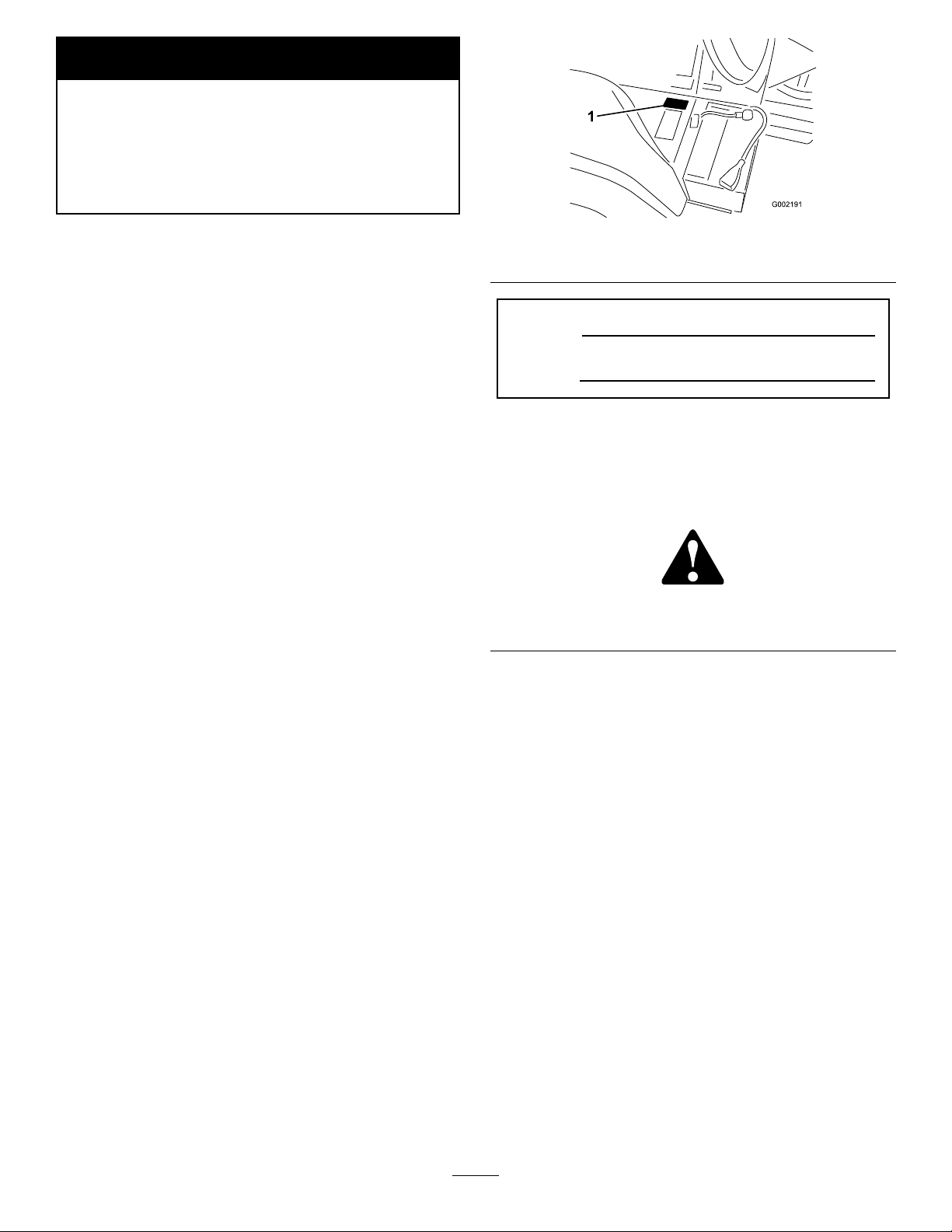
SafetyandInstructionalDecals
Safetydecalsandinstructionsareeasilyvisibletotheoperatorandarelocatednearanyareaof
potentialdanger.Replaceanydecalthatisdamagedorlost.
93-0688
1.Warning—readtheOperator’sManual.
2.Causticliquid/chemicalburnandtoxicgasinhalation
hazards—wearhand,skin,eye,andrespiratoryprotection.
94-3353
1.Crushinghazardofhand—keepyourhandsasafedistance
away.
94-7171
1.Lights
114-9600
1.ReadtheOperator’sManual.
93-6681
1.Cutting/dismemberment—hazard,fan-stayawayfrom
movingparts.
114-9600
1.ReadtheOperator’sManual.
93-6687
1.Donotstephere.
100-8619
1.Sprayon2.Sprayoff
104-7628
1.ReadtheOperator’sManual.
107-8722
1.Tosettheparkingbrake,pressthebrake,movetheparking
breaklevertothelockedposition.
8
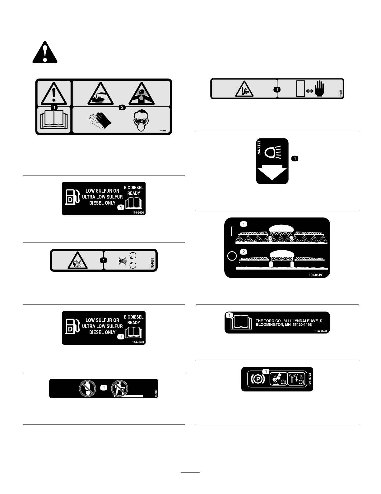
Page 9
1.Warning—readthe
Operator’sManual.
2.Lockandengage
3.Cruisecontrol
1.ReadtheOperator’s
Manual.
2.Engine—stop5.Engine—start
3.On
104-9129
4.On
5.Off
105-7506
4.Engine—preheat
106-1355
1.Warning—donotenterthetank.
106-5016
1.Warning—readtheOperator’sManual.
2.Electricshockhazard,overheadpowerlines—stayaway
fromoverheadpowerlines.
3.Crushinghazard,boom—keepbystandersasafedistance
fromthemachine.
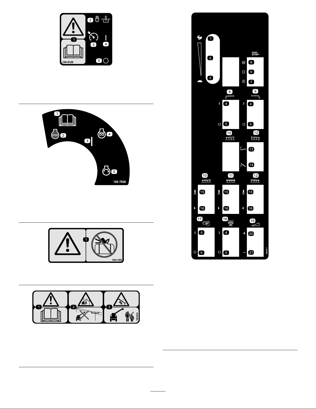
106-5217
1.Fast12.Rightboom
2.Continuousvariable
setting
3.Slow
4.On15.Sprayon
5.Off16.Sprayoff
6.Automatic17.Agitation
7.Manual18.Pump
8.Leftboomfoammarker19.Continuousvariable
9.Rightboomfoammarker
10.Leftboom
11.Centerboom
13.Lowertheboom.
14.Raisetheboom.
20.Increase
21.Decrease
9
setting,spraypressure
Page 10
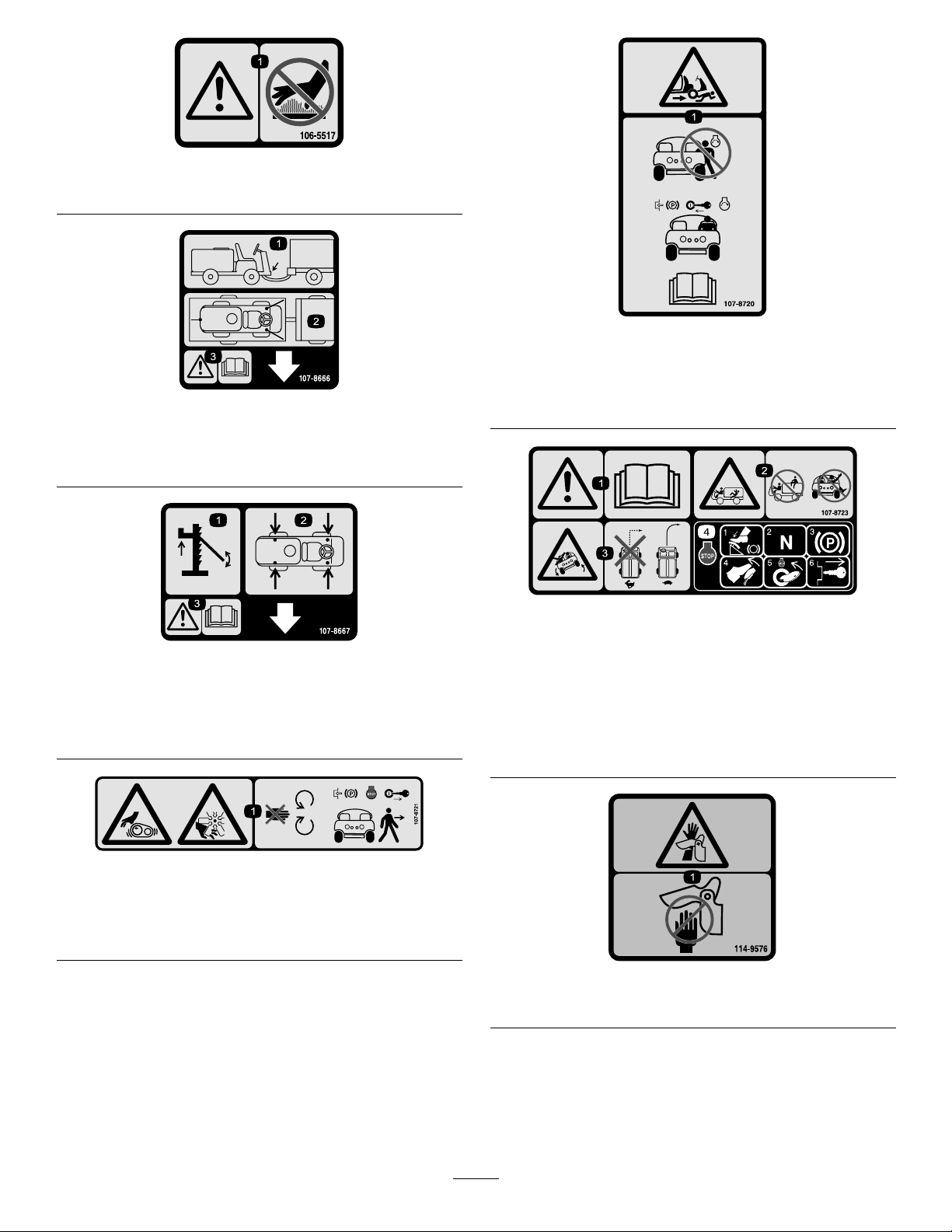
106-5517
1.Warning—donottouchthehotsurface.
107-8666
1.Towhitchlocation
2.Tiedownlocations
3.Warning—ReadtheOperator’sManual.
107-8667
1.Jacking
2.Jackpointlocations
3.Warning—ReadtheOperator’sManualformoreinformation
onjackingthevehicle
107-8720
1.Crushing/dismembermenthazard—donotstarttheengine
whileenteringorexitingthevehicle;engagetheparking
brake,insertthekey,andstarttheenginewhileseatedin
thedriversseat;readtheOperator’sManual.
107-8723
1.Warning—readtheOperator’sManual.
2.Falling,Crushinghazard—noridersontank;keeparms
andlegsinsideofthevehicleatalltimes.
3.Tippinghazard—donotturnsharplywhiletravelingfast;
driveslowlywhenturning.
4.Tostoptheengine,pressthebrake,putthegearselectorin
neutral,settheparkingbrake,releasethebrake,stopthe
engine,andremovethekey .
107-8721
1.Entanglementhazard,belt;cutting/dismembermenthazard,
fan—stayawayfrommovingparts;locktheparkingbrake,
stoptheengine,andremovethekeybeforeexitingthe
machine.
114-9576
1.Pinchpoint,hand—keephandawayfromhinge.
10
Page 11
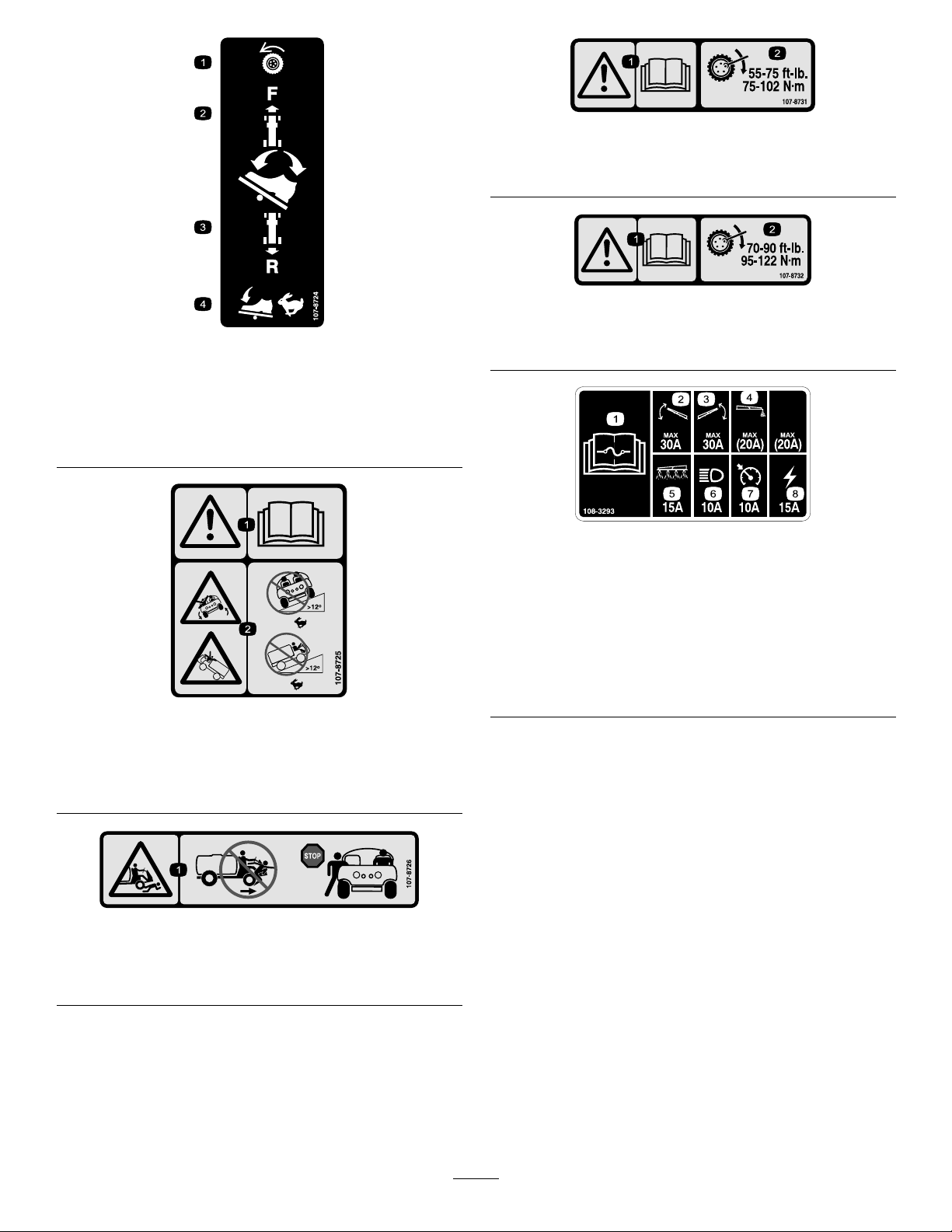
107-8724
1.Tractiondrive3.T odriveinreverse,press
2.Todriveforward,pressthe
topofthetractionpedal
forwardanddown.
thebottomofthepedal
rearwardanddown.
4.Vehiclespeedincreases
withmorepedalpressure.
107-8725
1.Warning—readtheOperator’sManual.
2.Tippinghazard—donotdrivefastacrossslopesgreater
than12degrees;donotdrivefastupslopesgreaterthan
12degrees.
107-8731
1.Warning—readtheOperator’sManual.
2.Torquelugnutsto55-75ft-lb(75-102N-m).
107-8732
1.Warning—readtheOperator’sManual.
2.Torquelugnutsto75-90ft-lb(95-122N-m).
108-3293
1.ReadtheOperator’s
Manualforinformationon
fuses.
2.30amp.fusefortheboom
lift,left
3.30amp.fusefortheboom
lift,right
4.20amp.fuseforthefoam
marker
5.15amp.fuseforthespray
6.10amp.fuseforthe
7.10amp.fuseforthecruise
8.15amp.fuseforthe
system
headlights
control
ignition
107-8726
1.Crushing/dismembermenthazardofbystanders—donot
exitorenterthemachinewhileitismoving;stopthe
machinebeforeenteringorexiting.
11
Page 12

Setup
LooseParts
Usethechartbelowtoverifythatallpartshavebeenshipped.
ProcedureDescription
1
2
Note:Determinetheleftandrightsidesofthemachinefromthenormaloperatingposition.
Important:Tousethesprayer,
Distributorforinformationontheavailableboomkitsandaccessories.Afteryouinstallyournozzlesand
beforeusingthesprayerforthersttime(ifyou
bypassvalvessothatthepressureandapplicationrateremainsthesameforallboomswhenyouturnone
ormoreboomsoff.RefertoCalibratingtheBoomBypassV alvessectionintheOperationsection.
Nopartsrequired
Ignitionkey2
Operator’sManual
EngineOperator’sManual
PartsCatalog
OperatorTrainingMaterial
RegistrationCard
Pre-deliveryInspectionSheet
y ou must obtain and install nozzles
do not
useProControl™SpraySystem),adjusttheboom
3.Attheboomhinge,measurethecompressionofthe
1
CheckingtheBoomHinge
Qty.
–
1
1
1
1
1
1
upperandlowerspringswhiletheboomsareintheir
extendedposition(Figure3).
A.Allspringsmustbecompresseduntilthemeasure
1.56inches.
Checktheboomhingesprings.
Readthemanualsandwatchthe
trainingmaterialsbeforeoperatingthe
machine.
.ContactyourAuthorizedT oro
Use
Springs
NoPartsRequired
Procedure
Important:Operatingthespraysystemwith
theboomhingespringsundertheincorrect
compressioncoulddamagetheboomassembly.
Measurethespringsandusethejamnutto
compressthespringsto1.56inchesifnecessary.
Thesprayisshippedwiththeboomextensionsswung
forwardtofacilitatepackagingofthemachine.The
springsarenotfullytightenedatthetimeofmanufacture
toallowtheboomstobeinthispositionfortransit.
Beforeoperatingthemachine,thespringsmustbe
adjustedtothecorrectcompression.
1.Ifnecessary,removethepackingcomponentsthat
securetherightandleftextensionboomsduring
shipping.
2.Supporttheboomswhiletheyareextendedtothe
sprayposition.
B.Usethejamnuttocompressanyspringthat
measuregreaterthan1.56inches.
12
Page 13
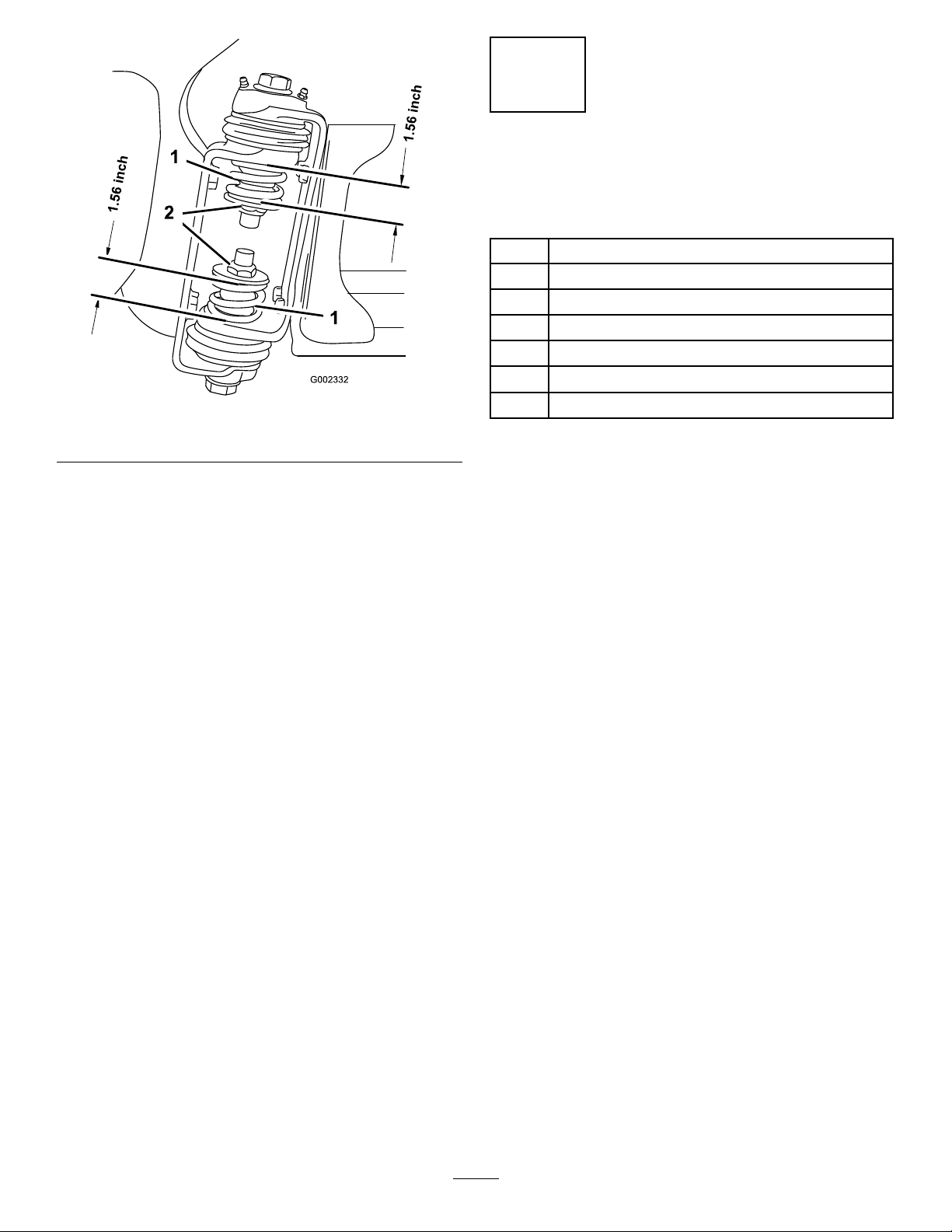
Figure3
1.Boomhingespring2.Jamnut
4.Repeattheprocedureforeachspringonbothboom
hinges.
5.Movetheboomsintothetransport“X”position.
SeeOperatingtheBoomsintheOperationsection
formoreinformation.
2
Learningmoreaboutyour
product.
Partsneededforthisprocedure:
2Ignitionkey
1
Operator’sManual
1
EngineOperator’sManual
1
PartsCatalog
1
OperatorTrainingMaterial
1
RegistrationCard
1
Pre-deliveryInspectionSheet
Procedure
1.Readthemanuals.
2.ViewtheOperatortrainingmaterial.
3.CompletetheregistrationcardandreturntoToro.
4.Storethedocumentationinasafeplace.
13
Page 14
ProductOverview
G002197
21467910
8
11
5
3
12
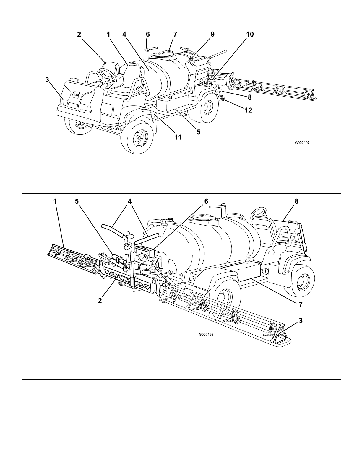
Figure4
1.Operator’sposition4.Chemicaltank
2.Passenger’sposition5.Fueltank8.Pump11.Battery
3.Headlight
6.Anti-SiphonReceptacle
7.Tanklid10.Pumppressuredampener
9.Freshwatertank12.Tankdrain
1.Leftboom
2.Centerboom
3.Rightboom5.Boomcontrolcylinder7.Hydraulictank
4.Boomtransportcradle6.Valvecluster8.Dashcluster
Figure5
14
Page 15
Controls
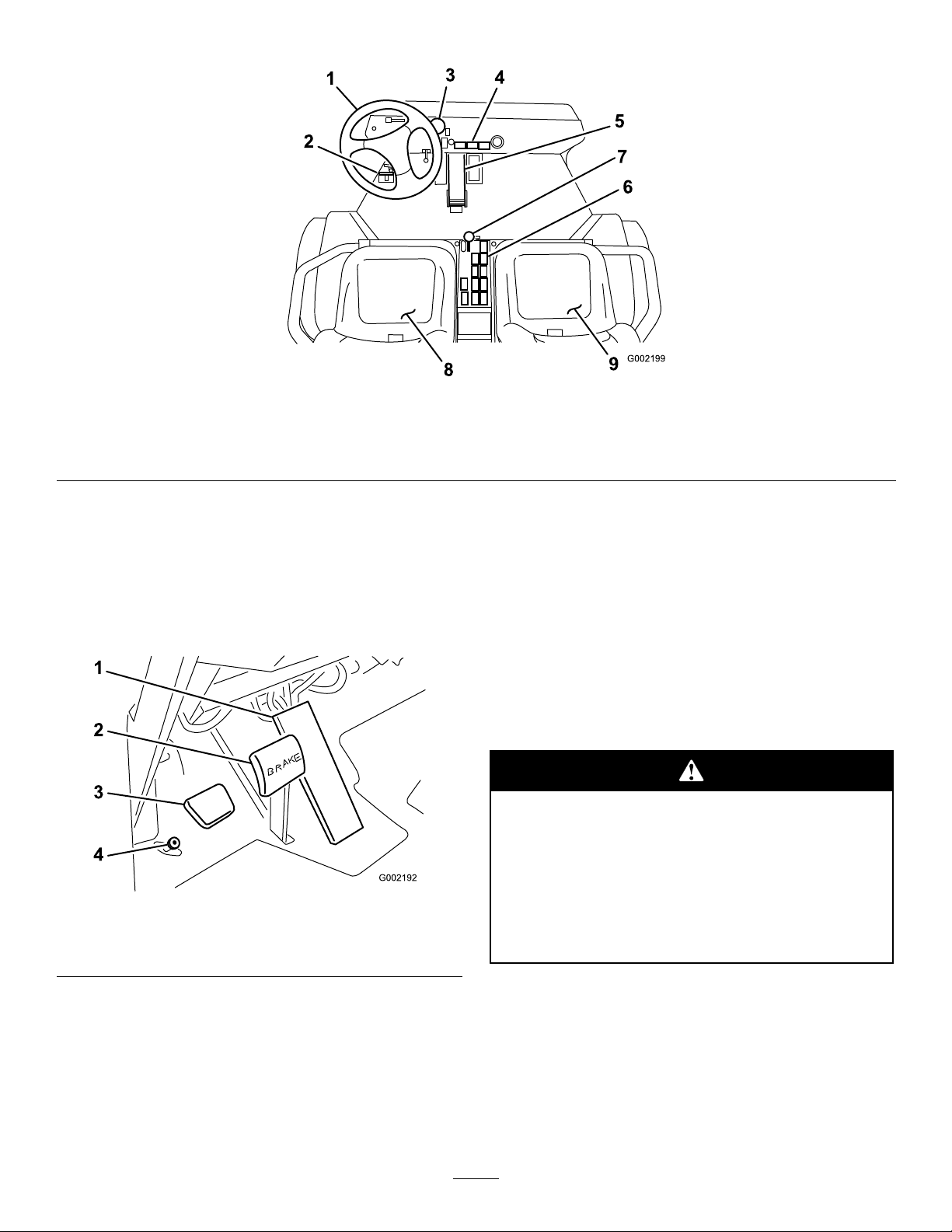
G002199
1
2
3
4
5
6
7
8
9
1.Steeringwheel
2.Masterboomfootswitch
3.Pressuregauge
Figure6
4.Dashcontrols7.Throttlelever
5.Tractionpedal
6.Sprayercontrols
8.Operator’sposition
9.Passengerposition
TractionPedal
Thetractionpedal(Figure7)controlsthemovementof
themachine,bothforwardandreverse.Usingtheheel
andtoeoftherightfoot,pressthetopofthepedalto
moveforwardorthebottomofthepedaltomovein
reverse.Releasethepedaltoslowandstop.
Figure7
1.Tractionpedal3.Parkingbrakepedal
2.Brakepedal4.Masterboomswitch
Fastpositionandpressthetractionpedalalltheway
forward.
Note:Toobtainmaximumpowerwithafulltankor
whentravelingupahill,setthethrottleleverintheFast
positionanddriveslowlysothattheengineremainsat
ahighrpm.
BrakePedal
Usethebrakepedaltostoporslowthesprayer
(Figure7).
Ifyouoperatethesprayerwithpoorlyadjusted
orwornbrakes,youcouldlosecontrolofthe
sprayer,resultinginseriousinjuryordeathto
youorbystanders.
Alwayscheckthebrakesbeforeoperatingthe
sprayerandkeepthemproperlyadjustedand
repaired.
Important:Ensurethatyouallowthesprayer
tocometoastopbeforeswitchingbetweenthe
ForwardandReverseposition.
Note:Thefartheryoupressthepedalineither
direction,thefasterthesprayerwilltravel.T oobtain
maximumforwardspeed,setthethrottlelevertothe
ParkingBrake
Theparkingbrakeisapedaltotheleftofthebrake
(Figure7).Engagetheparkingbrakewheneveryou
planonleavingtheseattopreventthesprayerfrom
accidentlymoving.Toengagetheparkingbrake,press
thebrakepedaland,whileholdingthebrake,pressthe
parkingbrakepedal.T odisengage,pressandreleasethe
15
Page 16
brakepedal.Ifthesprayerisparkedonasteepgrade,
applytheparkingbrakeandplacetheblocksonthe
downhillsideofthewheels.
ThrottleLever
PressureGauge
Thepressuregauge(Figure9).islocatedonthedash.
Thisgaugeshowsthepressureoftheuidinthesystem
inpsiandkPa.
Thethrottlelever,locatedonthecontrolpanelbetween
theseats(Figure8),controlsthespeedoftheengine.
Pushtheleverforwardtoincreasetheenginespeedand
pullitrearwardtodecreasetheenginespeed.
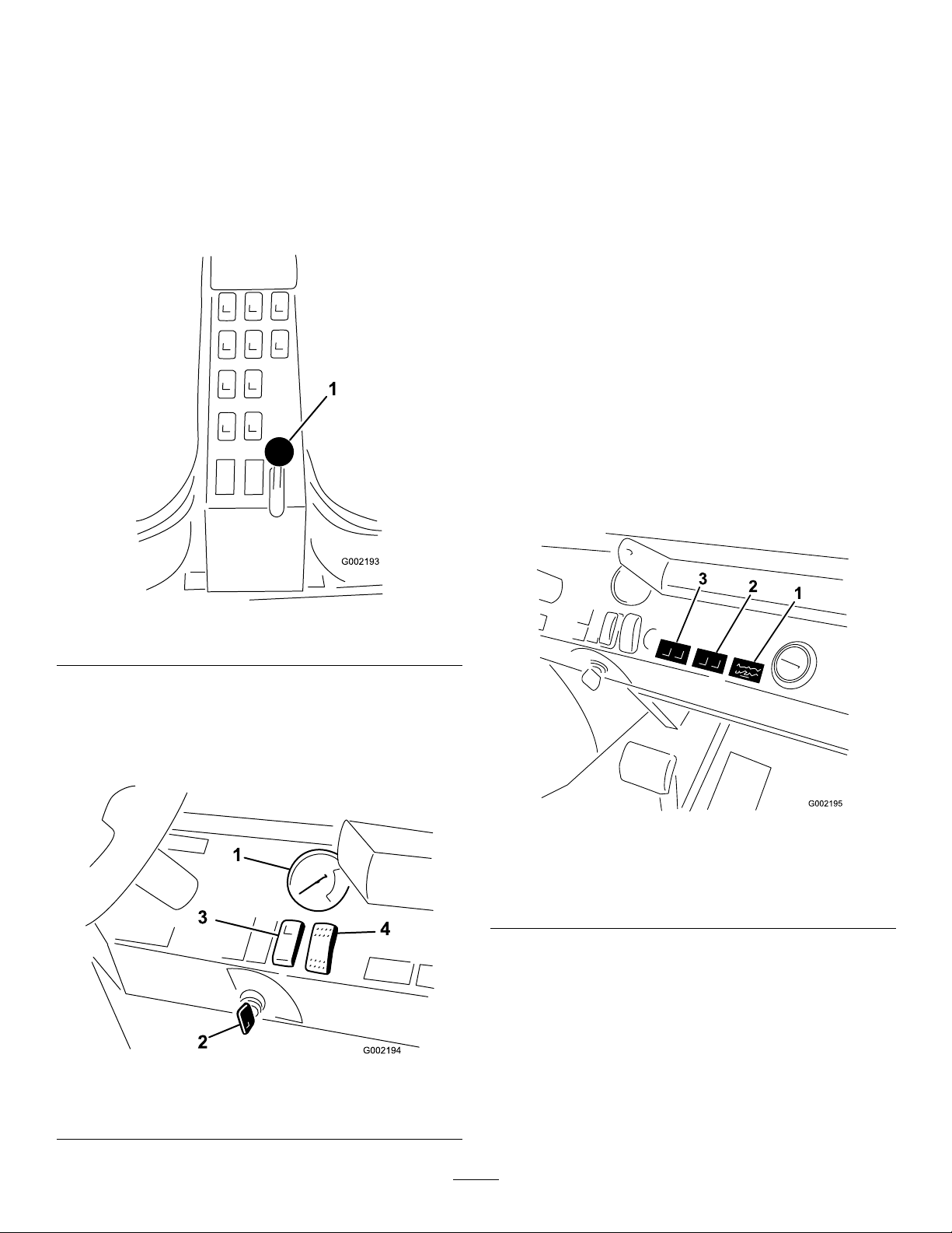
Figure8
1.Throttlelever
CruiseControlSwitch
Thecruisecontrolswitch(Figure9)lockstheposition
ofthetractionpedalatthetimetheswitchisengaged.
Thisensuresthesprayerstaysataconstantspeedwhile
drivingonlevelground.
HeadlightSwitch
Toggletheswitchtooperatetheheadlights(Figure9).
Pushitforwardtoturnthelightsonandrearwardto
turnthemoff.
HourMeter
Thehourmeter(Figure10)indicatesthetotalnumber
ofhourstheenginehasrun.Thehourmeterstartsto
functionwheneverthekeyisturnedtotheRunposition.
IgnitionSwitch
Theignitionswitch(Figure9)isusedtostartandstop
theengine,has3positions:Off,On/PreheatandStart.
Figure9
1.Pressuregauge3.Tractionpedallockswitch
2.Ignitionswitch4.Headlightswitch
Figure10
1.Hourmeter3.Watertemperatureand
glowpluglight
2.Oilpressureandbattery
light
FuelGauge
Thefuelgaugeislocatedontopofthefueltank
(Figure11),ontheleftsideofthemachineandshows
theamountoffuelinthetank.
16
Page 17
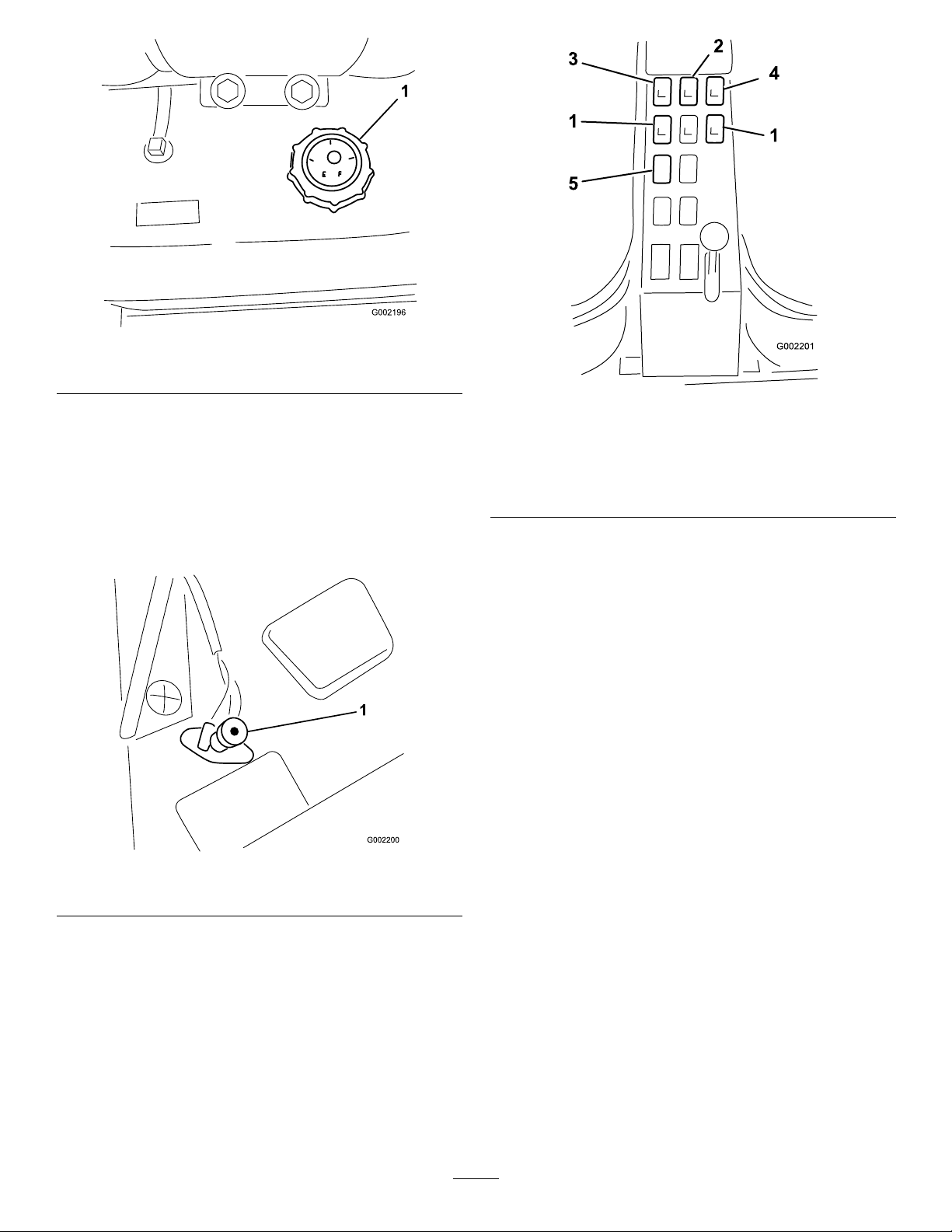
Figure11
1.Fuelgauge
MasterBoomSwitch
Themasterboomswitchislocatedontheoorboard
ofthemachinecabandtotheleftoftheoperator.It
allowsyoutostartorstopthesprayoperation.Press
theswitchwithyourfoottoenableordisablethespray
system(Figure12).
Figure13
1.Boomswitches,left,right
andcenter
2.Pumpswitch
3.Applicationrateswitch
4.Agitation
5.Boomliftswitch,leftand
right
PumpSwitch
Thepumpswitchislocatedonthecontrolpaneltothe
rightoftheseat(Figure13).Togglethisswitchforward
torunthepumporrearwardtostopthepump.When
theswitchisturnedon,alightontheswitchilluminates.
Important:Onlyengagethepumpswitchwhen
theengineisatlowidletoavoiddamagingthe
pumpdrive.
ApplicationRateSwitch
Figure12
1.Masterboomswitch
BoomSwitches
Theboomswitchesarelocatedonthecontrolpanelto
therightoftheseat(Figure13).Toggleeachswitch
forwardtoturnthecorrespondingboomsectiononand
rearwardtoturnthemoff.Whentheswitchisturned
on,alightontheswitchilluminates.Theseswitches
willonlyaffectthespraysystemwhenthemasterboom
switchison.
Theapplicationrateswitchislocatedonthecontrol
paneltotherightoftheseat(Figure13).Pressandhold
theswitchforwardtoincreasethespraysystempressure,
orpressandholditrearwardtodecreasepressure.
BoomLift
Theboomliftswitchesarelocatedonthecontrolpanel
totherightoftheseatandusedtoraisetheleftandright
boomrespectively(Figure13).
SonicBoom(Optional)
TheSonicBoomswitchisarockerswitchusedto
operatetheSonicBoom.T oggleswitchforwardfor
automatic,rearwardformanualandcenterforOff.The
sprayercomeswithplasticplugsintheselocations.
17
Page 18
FoamMarkerSwitchLocations
G002204
1
(Optional)
Ifyouinstallthefoammarkerkit,youwilladdswitches
tothecontrolpanelforcontrollingtheiroperation.The
sprayercomeswithplasticplugsintheselocations.
AgitationSwitch
Theagitationswitchislocatedonthecontrolpanelto
therightoftheseat(Figure13).Togglethisswitch
forwardtoturnontheagitationinthetankorrearward
tostoptheagitation.Whentheswitchisturnedon,a
lightontheswitchilluminates.Foragitationtowork,
thepumpmustbeonandtheenginemustberunning
aboveanidle.Theagitationvalveislocatedbehindthe
tank(Figure14)
Anti-siphonFillReceptacle
Tothefrontofthetankcoverisahosereceptaclewitha
threadedtting,a90degreebarbedtting,andashort
hosewhichyoucandirecttowardthetankopening.This
receptacleallowsyoutoconnectawaterhosetoitand
llthetankwithwaterwithoutcontaminatingthehose
withthechemicalsinthetank.
Important:Donotlengthenthehosetoallow
contactwiththetankuids.Thedistancefromthe
endofthehosetotheuppermostwaterlevelshould
bewithinlocalregulatorylimits.
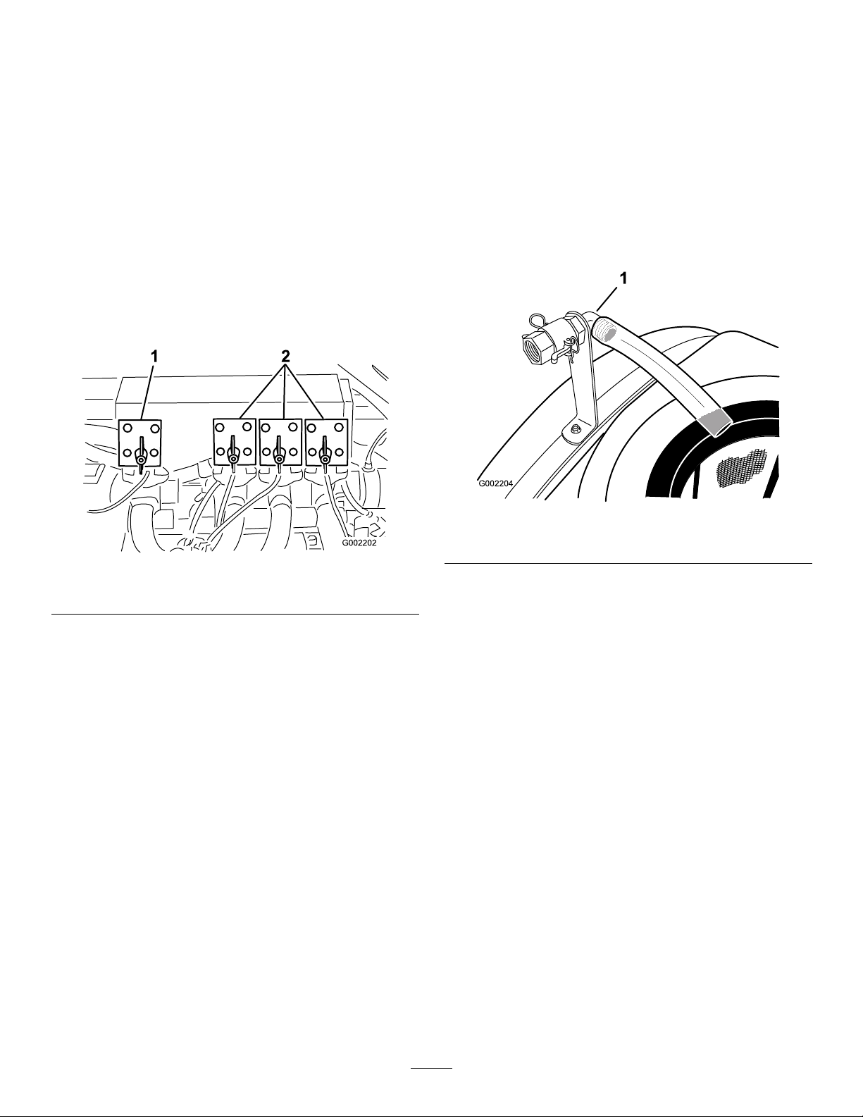
Figure14
1.Agitationvalve2.Boomvalves
BoomValves
Thesevalvesturnthethreeboomsonoroff(Figure14).
Ifyoueverneedtomanuallyturnoffaboom,rotate
theknobonthevalveclockwisetoturnthevalveoffor
counterclockwisetoturniton.
Note:Turningtheboomvalvemanuallycaninterfere
withthefunctionofthefuses.Thefusesshouldbe
checkedaftermanuallyrotatingthevalve.
BoomBypassValves
Theboombypassvalvesredirecttheuidowfora
boomtothetankwhenyouturnofftheboomsection.
Theyarelocatedatthebottomofeachboomvalve
section.Youcanadjustthesevalvestoensurethatthe
boompressureremainsconstantnomatterhowmany
boomsareon.RefertoCalibratingtheBoomBypass
ValvesintheOperationsection.
Figure15
1.Anti-siphonllreceptacle
TankCover
Thetankcoverislocatedinthecenterofthetopofthe
tank.Toopenit,turnofftheengine,thenturnthefront
halfofthecovertotheleftandswingitopen.Youcan
removethestrainerinsideforcleaning.T osealthetank,
closethecoverandrotatethefronthalftowardtheright.
Note:IfyouusetheProControl,youmustshutall
thebypassvalves.
18
Page 19

Specications
Note:Specicationsanddesignaresubjecttochange
withoutnotice.
Baseweight
Weightwithstandardspray
system,empty,without
operator
Weightwithstandardspray
system,full,withoutoperator
Maximumgrossvehicleweight
(GVW)(onlevelground)
Tankcapacity
Overallwidthwithstandard
spraysystemboomsstoredin
theXposition
2,700lb(1225kg)
2,700lb(1225kg)
5,645lb(2,560kg)
6,525lb(2,960kg)
300USgallons(1135.6L)
743/4inches(189cm)
Operation
Note:Determinetheleftandrightsidesofthe
machinefromthenormaloperatingposition.
ThinkSafetyFirst
Pleasecarefullyreadallofthesafetyinstructionsand
decalsinthesafetysection.Knowingthisinformation
couldhelpyouorbystandersavoidinjury.
BeforeDrivingtheSprayerfor
theFirstTime
ChecktheEngineOil
Overalllengthwithstandard
spraysystem
Overalllengthwithstandard
spraysystemtothetopofthe
boomsstoredintheXposition
Overallheightwithstandard
spraysystem
Overallheightwithstandard
spraysystemtothetopofthe
boomsstoredintheXposition
Groundclearance7.25inches(18.4cm)
Wheelbase
154inches(391cm)
174inches(442cm)
57.5inches(146cm)
91inches(231cm)
78inches(198cm)
OptionalEquipment
TheToroCompanyhasoptionalequipmentand
accessoriesthatyoucanpurchaseseparatelyandinstall
onyoursprayer.ContactyourAuthorizedService
Dealerforacompletelistofoptionalequipmentthatis
currentlyavailableforyoursprayer.
Note:Thebesttimetochecktheengineoiliswhen
theengineiscool,beforeithasbeenstartedforthe
day.Ifithasalreadybeenrun,allowtheoiltodrain
backdowntothesumpforatleast10minutesbefore
checking.Iftheoillevelisatorbelowthe’add’mark
onthedipstick,addoiltobringtheoilleveltothe’full’
mark.Donotoverll.Iftheoillevelisbetweenthe
’full’and’add’marks,nooiladditionisrequired.
Theengineisshippedwithoilinthecrankcase;
however,thelevelofoilmustbecheckedbeforeyou
rststarttheengineandafteryouhaverunit.
1.Positionthemachineonalevelsurface.
2.Removethedipstick,locatedunderthepassenger
seat,andwipeitwithacleanrag(Figure16).Insert
thedipstickintothetubeandmakesureitisseated
fully.Removethedipstickandchecktheoillevel.
Figure16
1.Dipstick
3.Iftheoillevelislow,removethellercapfrom
thevalvecover(Figure17)andpouroilintothe
openinguntiltheoillevelisuptotheFullmarkon
19
Page 20

thedipstick;refertoServicingEngineOil,inthe
EngineMaintenancesection,fortheproperoiltype
andviscosity.Addtheoilslowlyandcheckthelevel
oftenduringthisprocess.Donotoverll.
Figure17
1.Oilllercap
AddFuel
Incertainconditions,fuelisextremely
ammableandhighlyexplosive.Areor
explosionfromfuelcanburnyouandothers
andcandamageproperty.
•Fillthefueltankoutdoors,inanopenarea,
whentheengineiscold.Wipeupanyfuel
thatspills.
•Donotllthefueltankcompletelyfull.Add
fueltothefueltankuntilthelevelis1inch
(25mm)belowthebottomofthellerneck.
Thisemptyspaceinthetankallowsfuelto
expand.
•Neversmokewhenhandlingfuel,andstay
awayfromanopenameorwherefuel
fumesmaybeignitedbyaspark.
4.Installthellercap.
5.Installthedipstickrmlyinplace.
ChecktheTirePressure
Checkthetirepressureevery8hoursordailytoensure
properlevels.Fillthetiresto18psi(124kPa).Also,
checkthetiresforwearordamage.
•Storefuelinanapprovedcontainerandkeep
itoutofthereachofchildren.Neverbuy
morethana30-daysupplyoffuel.
20
Page 21

•Fuellterpluggingmaybeexpectedforatimeafter
convertingtobiodieselblendsd.
Incertainconditionsduringfueling,static
electricitycanbereleasedcausingaspark
whichcanignitethefuelvapors.Areor
explosionfromfuelcanburnyouandothers
andcandamageproperty.
•Alwaysplacefuelcontainersontheground
awayfromyourvehiclebeforelling.
•Donotllfuelcontainersinsideavehicle
oronatruckortrailerbedbecauseinterior
carpetsorplastictruckbedlinersmay
insulatethecontainerandslowthelossof
anystaticcharge.
•Whenpractical,removegas-powered
equipmentfromthetruckortrailerand
refueltheequipmentwithitswheelsonthe
ground.
•Ifthisisnotpossible,thenrefuelsuch
equipmentonatruckortrailerfroma
portablecontainer,ratherthanfromafuel
dispensernozzle.
•Contactyourdistributorifyouwishformore
informationonbiodiesel.
FillingtheFuelT ank
Thefueltankcapacityisapproximately10.6USgallons
(40l).
Note:Thefueltankcapcontainsagaugewhichshows
thefuellevel;checkitfrequently .
1.Positionthesprayeronalevelsurface.
2.Settheparkingbrake,stopthepump,stopthe
engine,removetheignitionkey,andallowthe
enginetocool.
3.Cleantheareaaroundthefueltankcap(Figure18).
•Ifafueldispensernozzlemustbeused,keep
thenozzleincontactwiththerimofthefuel
tankorcontaineropeningatalltimesuntil
fuelingiscomplete.
Recommendedfuel
TheenginerunsonNo.2-Dor1-Dautomotivetype
dieselfuelwithaminimumcetaneratingof40.
Note:Yourenginemayrequireahighercetane-rated
fuelifyouoperatethemachineathighaltitudesorin
lowatmospherictemperatures.
BiodieselReady
Thismachinecanalsouseabiodieselblendedfuel
ofuptoB20(20%biodiesel,80%petrodiesel).The
petrodieselportionshouldbeloworultralowsulfur.
Observethefollowingprecautions:
•Thebiodieselportionofthefuelmustmeet
specicationASTMD6751orEN14214.
•TheblendedfuelcompositionshouldmeetASTM
D975orEN590.
•Paintedsurfacesmaybedamagedbybiodiesel
blends.
•UseB5(biodieselcontentof5%)orlesserblends
incoldweather.
•Monitorseals,hoses,gasketsincontactwithfuelas
theymaybedegradedovertime.
Figure18
1.Fueltankcap
4.Removethefueltankcap.
21
Page 22

Undercertainconditions,dieselfuelandfuel
vaporsarehighlyammableandexplosive.A
reorexplosionfromfuelcanburnyouand
othersandcancausepropertydamage.
Note:Thesetiresaredifferentthancartires;they
requirelesspressuretominimizeturfcompaction
anddamage.
•Checkalluidlevelsandaddtheappropriate
amountofspecieduids,ifanyarefoundtobe
low .
•Useafunnelandllthefueltankoutdoors,
inanopenarea,whentheengineisoffand
iscold.Wipeupanyfuelthatspills.
•Donotllthefueltankcompletelyfull.Add
fueltothefueltankuntilthelevelis1inch
(25mm)belowthebottomofthellerneck.
Thisemptyspaceinthetankallowsthefuel
toexpand.
•Neversmokewhenhandlingfuel,andstay
awayfromanopenameorwherefuel
fumesmaybeignitedbyaspark.
•Storefuelinaclean,safety-approved
containerandkeepthecapinplace.
5.Fillthetanktoaboutoneinchbelowthetopofthe
tank,(bottomofthellerneck).
Note:Thisspaceinthetankallowsfueltoexpand.
Donotoverll.
6.Installthefueltankcapsecurely .
7.Wipeupanyfuelthatmayhavespilled.
•Checkthebrakepedaloperation.
•Checktoseethatthelightsareworking.
•Withtheengineoff,checkforoilleaks,looseparts,
andanyothernoticeablemalfunctions.
Ifanyoftheaboveitemsarenotcorrect,notifyyour
mechanicorcheckwithyoursupervisorbeforetaking
thesprayeroutfortheday.Yoursupervisormaywant
youtocheckotheritemsonadailybasis,soaskwhat
yourresponsibilitiesare.
DrivingtheSprayer
StartingtheEngine
1.Sitontheoperator’sseatandkeepyourfootoffthe
tractionpedal.
2.Ensurethattheparkingbrakeisengaged,the
tractionpedalisintheNeutralposition,thethrottle
isintheSlowposition.
3.TurntheignitionswitchtotheOn/Preheatposition.
AdjustingtheBoomstoLevel
1.Attheoperator’sposition,turntheignitionkeyto
Ontoenergizethesystem.
2.Movetheboomsintopositionsothattheyarelevel
withtheground.
3.Removethekeyandexittheoperator’sposition.
4.Atthehinge,adjustthepositionofthebumpersso
theboomcannotmovepastlevelwiththeground.
Takecaretomakesurethebumperislevel.
5.Tightentheboltandnuttolockthebumpersinto
theadjustedposition.Torquethefastenersto
135-165ft-lbs(183-223N-m).
Note:Thebumpermayexperiencesomecompression
overtime.Iftheboomsdropbelowlevel,usethis
proceduretoreadjustthebumperpositionneeded.
Pre-StartingChecks
Checkthefollowingitemseachtimeyoubeginusing
thesprayerfortheday:
Note:Anautomatictimerwillcontrolthepreheat
forapproximately6seconds.
4.Afterpreheating,turnthekeytotheStartposition.
5.Cranktheenginefornolongerthan15seconds.
6.Releasethekeywhentheenginestarts.
7.Iftheenginerequiresadditionalpreheating,turn
thekeytotheOffposition,thentotheOn/Preheat
position.
Note:Repeatstepsthroughasrequired.
8.Runtheengineatidlespeedorpartialthrottleuntil
theenginewarmsup.
Driving
1.Pressthetractionpedalforwardtodriveforwardor
rearwardtodriveinreverse.
Important:Ensurethatyouallowthesprayer
tocometoastopbeforeswitchingbetweenthe
ForwardandReversepositions.
2.Toslowlystopthesprayer,releasethetractionpedal.
•Checkthetirepressure.
3.Tostopquickly,pressthebrakepedal.
22
Page 23

Note:Stoppingdistancemayvarydependingon
thesprayerloadandspeed.
SettingtheCruiseControl
•Avoidhardbrakingsituationsfortherstseveral
hoursofnewsprayerbreak-inoperation.New
brakeliningsmaynotbeatoptimumperformance
untilseveralhoursofusehascausedthebrakesto
becomeburnished(broken-in).
•Avoidracingtheengine.
Ifyoupresstheswitchtoturnoffthecruise
controlanddonothaveyourfootonthetraction
pedal,thetractionunitmaysuddenlystopand
causeyoutolosecontrol,possiblyinjuringyou
orbystanders.
Ensurethatyouhaveyoufootonthetraction
pedalwhenyoudisengagethecruisecontrol
usingtheswitch.
1.Driveforwardandattainthedesiredspeed;refer
toDrivingtheSprayer.
2.Pressthetopofthecruisecontrolswitch.
Note:Thelightontheswitchilluminates.
3.Takeyourfootoffthetractionpedal.
Note:Thesprayerwillmaintainthespeedyouset.
4.Toreleasethecruisecontrol,eitherplaceyourfoot
onthetractionpedalandpressthebottomofthe
cruisecontrolswitchorremoveyourfootfromthe
tractionpedalandpressthebrakepedal.
Note:Thelightontheswitchturnsoffandthe
tractioncontrolreturnstothetractionpedal.
StoppingtheEngine
1.Pressthebraketostopthesprayer.
•Varythesprayerspeedduringoperation.Avoidfast
startsandquickstops.
•RefertotheMaintenancesectionforanyspecial
lowhourchecks.
AdjustingtheBoomstoLevel
Thefollowingprocedurecanbeusedtoadjustthe
hardstopsonthecenterboomtokeeptheleftandright
boomsatlevel.
1.Attheoperator’sposition,turntheignitionkeyto
Ontoenergizethesystem.
2.Movetheboomsintopositionsothattheyarelevel
withtheground.
3.Removethekeyandexittheoperator’sposition.
4.Atthehinge,adjustthepositionofthebumpersso
theboomcannotmovepastlevelwiththeground.
Takecaretomakesurethebumperislevel.
5.Tightentheboltandnuttolockthebumpersinto
theadjustedposition.Torquethefastenersto
135-165ft-lbs(183-223N-m).
Note:Thebumpermayexperiencesomecompression
overtime.Iftheboomsdropbelowlevel,usethis
proceduretoreadjustthebumperpositionneeded.
2.MoveallthecontrolstotheNeutralposition.
3.Settheparkingbrake.
4.ShiftthethrottlelevertotheIdleposition.
5.TurntheignitionkeytotheOffposition.
6.Removethekeyfromtheswitchtoprevent
someonefromaccidentallystartingtheengine.
NewSprayerBreak-In
Toprovideproperperformanceandlongsprayerlife,
followtheseguidelinesfortherst100operatinghours:
•Checktheuidandengineoillevelsregularly
andbealertforindicationsofoverheatinginany
componentofthesprayer.
•Afterstartingacoldengine,letitwarmupforabout
15secondsbeforeaccelerating.
OperatingtheSprayer
TooperatetheMulti-ProSprayerrstllthespraytank,
thenapplythesolutiontotheworkarea,andnally
cleanthetank.Itisimportantthatyoucompleteall
threeofthesestepsinsuccessiontoavoiddamagingthe
sprayer.Forexample,donotmixandaddchemicalsin
thespraytankatnightandthensprayinthemorning.
Thiswouldleadtoseparationofthechemicalsand
possibledamagetothesprayercomponents.
23
Page 24

Chemicalsarehazardousandcancause
personalinjury.
•Readthedirectionsonthechemicallabels
beforehandlingthechemicalsandfollow
allmanufacturerrecommendationsand
precautions.
•Keepchemicalsawayfromyourskin.
Shouldcontactoccur,washtheaffectedarea
thoroughlywithsoapandcleanwater.
•Weargogglesandanyotherprotective
equipmentrecommendedbythechemical
manufacturer.
Toopenthefreshwatertankspigot,turntheleveron
thespigot.
TheMulti-ProSprayerhasbeenspecicallydesignedto
havehighdurabilityinordertogiveitthelongsprayer
lifeyouneed.Differentmaterialshavebeenchosenfor
specicreasonsatdifferentlocationsonyoursprayerto
meetthisgoal.Unfortunatelythereisnosinglematerial
whichisperfectforallforeseeableapplications.
Somechemicalsaremoreaggressivethanothers
andeachchemicalinteractsdifferentlywithvarious
materials.Someconsistencies(e.g.wettablepowders,
charcoal)aremoreabrasiveandleadtohigherwear
rates.Ifachemicalisavailableinaformulationthat
wouldprovideincreasedlifetothesprayer,usethis
alternativeformulation.
Asalways,remembertocleanyoursprayerthoroughly
afterallapplications.Thiswilldothemosttoensure
yoursprayerhasalongandtroublefreelife.
FillingtheFreshWaterTank
Alwaysllthefreshwatertankwithcleanwaterbefore
handlingormixinganychemicals.
Thefreshwatertankislocatedattherear,leftside
ofthechemicaltank(Figure19).Itsuppliesasource
offreshwaterforyoutowashchemicalsoffofyour
skin,eyes,orothersurfacesinthecaseofaccidental
exposure.
Figure19
1.Freshwatertank
2.Fillercap
3.Spigot
FillingtheSprayTank
Important:Ensurethatthechemicalsyouwill
beusingarecompatibleforusewithViton(see
themanufacturer’slabel;itshouldindicateifit
isnotcompatible).Usingachemicalthatisnot
compatiblewithVitonwilldegradetheO-ringsin
thesprayer,causingleaks.
Important:Thetankmarkingsareforreference
onlyandcannotbeconsideredaccuratefor
calibration.
1.Stopthesprayeronalevelsurface,movetherange
selectortotheNeutralposition,stoptheengine,
andsettheparkingbrake.
2.Determinetheamountofwaterneededtomixthe
amountofchemicalyouneedasprescribedbythe
chemicalmanufacturer.
3.Openthetankcoveronthespraytank.
Thetankcoverislocatedinthecenterofthetop
ofthetank.T oopenit,turnthefronthalfofthe
covercounterclockwiseandswingitopen.You
canremovethestrainerinsideforcleaning.Toseal
thetank,closethecoverandrotatethefronthalf
clockwise.
4.Add3/4oftherequiredwatertothespraytank
usingtheanti-siphonllreceptacle.
Important:Alwaysusefreshcleanwaterin
thespraytank.Donotpourconcentrateinto
anemptytank.
24
Page 25

5.Starttheengine,setthepumpswitchtotheOn
position,andmovethethrottlelevertoahigheridle.
6.SettheagitationswitchtotheOnposition.
Important:Priortointroducingwettable
powdersintoanyToroSpraySystemmixthe
powdersinasuitablecontainerwithsufcient
freshwatertocreateafreeowingslurry.Best
resultsmaybeobtainedbyusingwarmwater.
Failuretodosomayresultinchemicaldeposits
onthebottomofthetank,degradedagitation,
cloggingofltersandimproperagitationrates.
7.Addtheproperamountofchemicalconcentrateto
thetank,asdirectedbythechemicalmanufacturer.
8.Addtheremainingwatertothetank.
OperatingtheBooms
Theboomliftswitchesonthesprayercontrolpanel
allowsyoutomovetheboomsbetweentransport
positionandspraypositionwithoutleavingthe
Operator’sseat.Itisrecommendedtochangeboom
positionswhilethemachineisstationary.
Tochangetheboomposition:
1.Stopthesprayeronlevelground.
2.Usetheboomliftswitchestolowerbooms.W ait
untiltheboomsreachthefull,extendedspray
position.
3.Whentheboomsneedtoberetracted,stopthe
sprayeronlevelground.
4.Usetheboomliftswitchestoraisethebooms.Raise
theboomsuntiltheyhavemovedcompletelyinto
boomtransportcradleformingthe“X”transport
positionandtheboomcylindersarefullyretracted.
theboom(s)backintothetransportposition.Make
suretheboomcylindersarefullyretractedtoprevent
actuatorroddamageduringstorage.
Spraying
Important:Inordertoensurethatyoursolution
remainswellmixed,usetheagitationfeature
wheneveryouhavesolutioninthetank.For
agitationtowork,thepumpmustbeonandthe
enginemustberunningaboveanidle.
Note:Thisprocedureassumesthatthepumpison
fromtheFillingtheSprayTankprocedure.
1.SetthemasterboomswitchtotheOffposition.
2.Adjustthethrottletothedesiredpositiontospray
at.
3.Drivetothelocationwhereyouwillbespraying.
4.Lowertheboomsintoposition.
5.Settheindividualboomswitches,asneeded,tothe
Onpositions.
6.Usetheapplicationrateswitchtoachievethe
desiredpressureasindicatedintheNozzleSelection
Guideprovidedwiththesprayer.
7.Driveatthedesiredspeedandthensetthemaster
boomswitchtotheOnpositiontobeginspraying.
Note:Whenthetankisnearlyempty ,theagitation
maycausefoaminginthetank.Inthiscase,turn
theagitationswitchoff.Alternatively,youcanuse
ananti-foamingagentinthetank.
8.Whennishedspraying,setthemasterboomswitch
totheOffpositiontoturnoffallbooms,thenset
thepumpswitchtotheOffposition.
TheBoomTransportCradle
Thesprayerisequippedwithaboomtransportcradle
thathasauniquesafetyfeature.Intheeventof
accidentalboomcontactwithalowoverheadobject
whileinthetransportposition,theboom(s)canbe
pushedoutofthetransportcradles.Ifthisoccurs,the
boomswillcometorestinanearhorizontalposition
totherearofthevehicle.Whiletheboomswillnot
bedamagedduetothismovement,theyshouldbe
immediatelyputbackintothetransportcradle.
Important:Theboomscanbedamagedby
transportingtheminanypositionotherthanthe
“X”transportpositionusingtheboomtransport
cradle.
Toputtheboomsbackintothetransportcradle,
lowertheboom(s)tothesprayposition,andthenraise
Note:Returntheboomstothetransportposition
anddrivethesprayertothecleaningarea.
Important:Alwaysraisetheboomsuntilthey
havemovedcompletelyintoboomtransport
cradleformingthe“X”transportpositionand
theboomcylindersarefullyretractedwhenever
youmovethesprayerfromonesprayingareato
anotherormovetoastorageorcleaningarea.
TurfCarePrecautionsWhile
OperatinginStationaryModes
Important:Undersomeconditions,heatfrom
theengine,radiator,andmufercanpotentially
damagegrasswhenoperatingthesprayerina
stationarymode.Stationarymodesincludetank
25
Page 26

agitation,handsprayingwithaspraygun,orusing
awalkingboom.
1.Stopthesprayeronalevelsurface,stoptheengine,
andsettheparkingbrake.
Usethefollowingprecautions:
•Avoidstationarysprayingwhenconditionsarevery
hotand/ordry,asturfcanbemorestressedduring
theseperiods.
•Avoidparkingontheturfwhilestationaryspraying.
Parkonacartpathwheneverpossible.
•Minimizetheamountoftimethemachineisleft
runningoveranyparticularareaofturf.Bothtime
andtemperatureaffecthowmuchthegrassmaybe
damaged.
•Settheenginespeedaslowaspossibleto
achievethedesiredpressureandow .Thiswill
minimizetheheatgeneratedandtheairvelocity
fromthecoolingfan.
•Allowheattoescapeupwardfromtheengine
compartmentbyraisingtheseatassembliesduring
stationaryoperationratherthanbeingforcedout
underthevehicle.
SprayingTips
•Donotoverlapareasthatyouhavepreviously
sprayed.
•Watchforpluggednozzles.Replaceallwornor
damagednozzles.
2.SetthemasterboomswitchtotheOffpositionand
setthepumpswitchtotheOffposition.
3.Rotatetheturretofthenozzlesineitherdirection
tothecorrectnozzle.
CleaningtheSprayer
Important:Youmustalwaysemptyandcleanthe
sprayerimmediatelyaftereachuse.Failuretodo
somaycausethechemicalstodryorthickeninthe
lines,cloggingthepumpandothercomponents.
Cleanthespraysystemaftereachsprayingsession.To
properlycleanthespraysystem:
•Usethreeseparaterinses.
•Useaminimumof50gallonsforeachrinse.
•Usethecleanersandneutralizersasrecommended
bythechemicalmanufacturers.
•Usepurecleanwater(nocleanersorneutralizers)
forthelastrinse.
1.Stopthesprayer,settheparkingbrake,andturnoff
theengine.
2.Locatethetankdrainvalveontherearofthe
machine(Figure20).Thevalveistotherearof
pump,attachedtothesupportbracket.
•Usethemasterboomswitchtostopthesprayow
beforestoppingthesprayer.Oncestopped,use
theneutralenginespeedcontroltoholdtheengine
speeduptokeeptheagitationrunning.
•Youwillobtainbetterresultsifthesprayeris
movingwhenyouturntheboomson.
UncloggingaNozzle
Ifanozzlebecomescloggedwhileyouarespraying,
youcancleanitusingahandspraybottleofwaterora
toothbrush.
1.Stopthesprayeronalevelsurface,stoptheengine,
andsettheparkingbrake.
2.SetthemasterboomswitchtotheOffpositionand
thensetthepumpswitchtotheOffposition.
3.Removethecloggednozzleandcleanitusinga
spraybottleofwateroratoothbrush.
SelectingaNozzle
Theturretbodiescanacceptupto3differentnozzles.
Toselectthedesirednozzle:
Figure20
1.Tankdrainhandle
Openthevalvetodrainanyunusedmaterial
fromthetankanddisposeofitaccordingtolocal
codesandthematerialmanufacturer’ sinstructions
(Figure21).Afterdraining,removethelynchpinon
thebracketsecuringthedrainvalvetothemachine
andletthevalverestontheground.Thisallows
anyresidualmaterialinthelinetodrain.
26
Page 27

2
3
1
G005593
13.Repeatsteps4through12atleast2moretimesto
ensurethatthespraysystemisfullycleaned.
Important:Y oumustalwayscompletethis
procedureatleast3timestoensurethatthe
spraysystemisfullyclean,preventingdamage
tothesystem.
14.Cleanthestrainer;refertoCleaningtheSuction
StrainerinCleaningsection.
Important:Ifyouusedwettablepowder
chemicals,cleanthestraineraftereachtank.
15.Usingagardenhose,rinseofftheoutsideofthe
sprayerwithcleanwater.
16.Removethenozzlesandcleanthembyhand.
Replacedamagedorwornnozzles.
CalibratingtheBoomBypass
Valves
Figure21
1.Valveopen3.Valveclosed
2.Lynchpin
3.Whenthetankhasdrainedcompletely ,install
thevalvetoframewiththelynchpinremoved
previouslyandclosethedrainvalve(Figure21).
4.Fillthetankwithatleast50USgallons(190L)of
cleanfreshwaterandclosethecover.
Note:Youcanuseacleaning/neutralizingagentin
thewaterasneeded.Onthenalrinse,useonly
clean,clearwater.
5.Lowertheboomsintothesprayposition.
6.Starttheengineandmovethethrottlelevertoa
higheridle.
7.EnsurethattheagitationswitchisintheOn
position.
8.SetthepumpswitchtotheOnpositionandusethe
applicationrateswitchtoincreasethepressureto
ahighsetting.
9.Setthemasterboomswitchandboomcontrol
switchestotheOnpositionstobeginspraying.
10.Allowallofthewaterinthetanktosprayout
thoughthenozzles.
11.Checkthenozzlestoensurethattheyareall
sprayingcorrectly.
12.SetthemasterboomswitchtotheOffposition,
setthepumpswitchtotheOffposition,andstop
theengine.
Important:IfyouhavetheProControl™Spray
Systeminstalled,theboombypassvalvesmustbe
closed.Usethefollowingadjustmentonlywhen
not
youare
usingtheProControlSpraySystem.
Beforeusingthesprayerforthersttimeorifthe
nozzlesarechanged,adjusttheboombypassvalvesso
thatthepressureandapplicationrateremainsthesame
forallboomswhenyouturnoneormoreboomsoff.
Note:Theboombypassvalvesmustbecalibrated
eachtimethenozzlesarechanged.
Selectanopenatareatoperformthisprocedure.
1.Fillthespraytankwithcleanwater.
2.Puttheextensionboomsdown,ifinstalled.
3.Settheparkingbrakeandstarttheengine.
4.MovethethrottlelevertotheSprayposition.
5.SetthepumpswitchtotheOnpositiontostart
thepump.
6.Setallthreeboomswitchesandthemasterboom
switchtotheOnposition.
7.Usetheapplicationrateswitchtoadjustthepressure
asreadonthepressuregaugeuntilitisintherange
forthenozzlesyouinstalledonthebooms(typically
40psi).
8.Recordthereadingonthepressuregauge.
9.Turnoffoneoftheboomsusingtheappropriate
boomswitch.
10.Adjusttheboombypassvalve(Figure22)underthe
boomcontrolvalvefortheboomyouturnedoff
27
Page 28

untilthepressurereadingonthegaugeisthesame
asitwasinstep7.
Figure22
1.Boombypassvalves
11.Turntheboomonandofftoverifythepressure
doesnotchange.
12.Repeatsteps9through11fortheotherbooms.
13.Drivethesprayeratthedesiredspeedwhilespraying
andturneachboomoffindividually.Thepressure
onthegaugeshouldnotchange.
Pump
pressureinthedampeneris1/3ofthespraying
pressure.Ifusingaspraypressuregreaterthan45psi
(3.1bar)adjustthedampeneraccordingly.
TransportingtheSprayer
Formovingthesprayerlongdistances,useatrailer.
Securethesprayertothetrailer.Figure24and
Figure25illustratethetie-downpoints.
Figure24
1.Tiedownpoints
Thepumpislocatednearthebackofthetankonthe
leftside(Figure23).
Figure23
1.Pump3.Pressuredampener
2.Greasetting
Figure25
1.Reartie-downpoint
TowingtheSprayer
Incaseofanemergency,thesprayercanbetowedfora
shortdistanceafteryouopenthetowvalve.However,
wedonotrecommendthisasastandardprocedure.
Towingatexcessivespeedscouldcausealoss
ofsteeringcontrol,resultinginpersonalinjury.
AdjustingtheAirPressurein
Dampener
Theairpressureinthedampeneronthepumpissetat
15psi(1bar)bythemanufacturer.Therecommended
Nevertowthesprayerfasterthan3mph(4.8
kph).
28
Page 29

Towingthesprayerisatwopersonjob.Ifthemachine
mustbemovedaconsiderabledistance,transportiton
atruckortrailer;refertoTransportingtheSprayer.
1.Rotatethetowvalve(Figure26)90degreesineither
directiontoopenit.
Figure28
1.Reartowingpoints
3.Releasetheparkingbrake.
4.Towthesprayeratlessthan3mph(4.8kph).
5.Whennished,closethetowvalveandtorqueitto
nomorethan5to8ft-lb(7to11N-m).
Figure26
1.Towvalve
Important:Ifyoudonotopenthetowvalve
beforetowingthesprayeryouwilldamagethe
transmission.
2.Afxatowlinetotheframe.Refertothefrontand
reartowingpointsinFigure27andFigure28.
Figure27
1.Fronttowingpoints
29
Page 30

Maintenance
Note:Determinetheleftandrightsidesofthemachinefromthenormaloperatingposition.
RecommendedMaintenanceSchedule(s)
MaintenanceService
Interval
Aftertherst5hours
Aftertherst8hours
Aftertherst50hours
Aftertherst200hours
Beforeeachuseordaily
Every50hours
Every100hours
MaintenanceProcedure
•Replacethehydraulicoillter.
•T orquethewheellugnuts.
•Changetherearplanetarygearboxuid.
•Checkthefan/alternatorbelt
•Changetheengineoil(includingsyntheticoil)andoillter.
•Checkthefuellinesandconnections.
•Packthefrontwheelbearings.
•Checktheairlter,cap,andvalveforwearordamage.
•Checktheengineoil.
•Checkthetirepressure.
•Checkthecoolantlevel.
•Checkthebrakes.
•Checkthehydraulicoillevel.
•Cleanthesuctionstrainer.(Moreoftenwhenusingwettablepowders)
•Lubricatethepump.
•Lubricateallgreasettings.
•Checkthebatterycableconnections.
•Lubricatetheboomhinges.
•Servicetheaircleaner .(moreoftenindusty,dirtyconditions).
•T orquethewheellugnuts.
•Inspecttheconditionandwearofthetires.
•Checkthecoolingsystemhosesforwearanddamage.
•Checkthefan/alternatorbelt
Every150hours
Every200hours
Every400hours
•Replacetheengineoillter.
•Changetheengineoil,includingsyntheticoil(moreoftenwhenoperatingunder
heavyloadorinhightemperature).
•Checkfrontwheeltoe-in.
•Cleantheradiatorns.
•Inspectallhosesandconnectionsfordamageandproperattachment.
•Greasetheactuatorrodbearings.
•Completeallyearlymaintenanceprocedurespeciedintheengineoperator’s
manual.
•Checkthefuellinesandconnections.
•Drainandcleanthefueltank.
•Replacethefuelltercanister.
•Replacethein-tankfuellter.
•Packthefrontwheelbearings.
•Changetheplanetarygearboxuid.
•Checkthecoolant(asdirectedbythemanufacturer)andchangeifnecessary.
•Replacethehydraulicoillter.
•Changethehydraulicoil.
•InspecttheO-ringsinthevalveassembliesandreplacethemifnecessary.
•Inspectthepumpdiaphragmandreplaceifnecessary.(seeanAuthorizedT oro
ServiceDistributor)
•Inspectthepressuredampenerbladderandreplaceifnecessary.(seeanAuthorized
ToroServiceDistributor)
30
Page 31

MaintenanceService
Interval
MaintenanceProcedure
•Inspectthepumpcheckvalvesandreplaceifnecessary.(seeanAuthorizedT oro
ServiceDistributor)
•Checkboomactuatorhydraulicoilforairbubbles.
•Inspectthenylonpivotbushings.
•FlushthesprayerwithcleanwaterusingtheCleaningtheSprayerprocedure.During
Yearly
therinseprocedure,increasepumpspeedtoopenreliefvalve;purgingvalvesand
hosesofresidualuids.
Important:Refertoyourengine
DailyMaintenanceChecklist
Duplicatethispageforroutineuse.
Checkthebrakeandparkingbrake
operation.
Checktheneutrallockoutswitchoperation.
Checkthefuellevel.
Checktheengineoillevel.
Checkthehydraulicoillevel.
Checkthecoolantlevel.
Inspecttheairlter.
Inspecttheradiatorandoilcoolerfor
debris.
Checkanyunusualenginenoises.
Checkanyunusualoperatingnoises.
Checkthetirepressure.
Checkforuidleaks.
Checkallhydraulicanduidhosesfor
damage,kinks,orwear.
Checktheinstrumentoperation.
Checktheacceleratoroperation.
Cleanthesuctionstrainer.
Lubricateallgreasettings.
Touchupanddamagedpaint.
1
Operator’ s Man ual
Fortheweekof: MaintenanceCheckItem
Mon.Tues.Wed.Thurs.Fri.
foradditionalmaintenanceprocedures.
Sat.Sun.
1
Immediatelyaftereverywashing,regardlessoftheintervallisted
31
Page 32

NotationforAreasofConcern
G002215
1
G002216
1
Inspectionperformedby:
ItemDate
1
2
3
4
5
6
7
8
9
10
Ifyouleavethekeyintheignitionswitch,someonecouldaccidentlystarttheengineandseriously
injureyouorotherbystanders.
Information
Removethekeyfromtheignitionbeforeyoudoanymaintenance.
Premaintenance
Procedures
JackingtheSprayer
Whenevertheengineisrunforroutinemaintenance
and/orenginediagnostics,therearwheelsofthesprayer
shouldbe1inch(25mm)offofthegroundwiththe
rearaxlesupportedonjackstands.
Asprayeronajackmaybeunstableandslipoff
ofthejack,injuringanyonebeneathit.
•Donotstarttheenginewhilethesprayeris
onajack.
•Alwaysremovethekeyfromtheignition
beforegettingoffofthesprayer.
Figure29
1.Frontjackingpoints
Thejackingpointattherearofthesprayerisonthe
rearsidewheretheboomsupportsareFigure30and
Figure31.
•Blockthetireswhenthesprayerisonajack.
Thejackingpointatthefrontofthesprayerisunderthe
frontaxle,directlyundertheleafsprings(Figure29)
Figure30
1.Rearjackingpoints
32
Page 33

Lubrication
GreasingtheSprayer
ServiceInterval:Every50hours—Lubricatethepump.
Every50hours/Yearly(whichever
comesrst)
GreaseType:No.2general-purposelithiumbase
grease.T oroPremiumAllPurposeGreaseisavailable
fromyouToroDistributor.
1.Rearjackingpoint(2)
Figure31
1.Wipethegreasettingcleansothatforeignmatter
cannotbeforcedintothebearingorbushing.
2.Pumpgreaseintothebearingorbushing.
3.Wipeoffexcessgrease.
Thegreasettingspositionsareillustratedbythe
following:Figure32throughFigure34.
33
Figure32
Pump(Donotovergrease,greasewillnotpurge)
1.Greasepoint
Page 34

Figure33
Threeinsideeachfrontwheel
2.Pumpgreaseintothebearingorbushingateach
ttingFigure35.
1.Greasepoint
Figure34
Oneoneachsideofthecenteringarm,betweenthetank
andtheenginecompartment
1.Greasepoint
Figure35
Rightboom
1.Greasetting
3.Wipeoffexcessgrease.
4.Repeattheprocedureforeachboompivot.
GreasingtheActuatorRod
Bearings
ServiceInterval:Every400hours/Yearly(whichever
comesrst)
GreaseType:No.2general-purposelithiumbase
grease.
1.Extendtheboomstothesprayposition.
2.Removethecottezrpinfromthepivotpin
(Figure36).
GreasingtheBoomHinges
ServiceInterval:Every100hours
Important:Iftheboomhingeiswashedwith
water,allwateranddebrismustbeclearedfromthe
hingeassemblyandfreshgreasemustbeapplied.
GreaseType:No.2general-purposelithiumbase
grease.
1.Wipethegreasettingscleansothatforeignmatter
cannotbeforcedintothebearingorbushing.
34
Page 35

G002016
1
4
2
3
5
Figure36
1.Actuator
2.Actuatorrod5.Pin
3.Boompivotpinhousing
7.Withthepininplace,releasetheboomandsecure
thepinwiththecotterremovedpreviously.
8.Repeattheprocedureforeachactuatorrodbearing.
4.Cotter
3.Liftupontheboomandremovethepin(Figure36).
Slowlylowertheboomtothehardstop.
4.Inspectthepinforanydamage,replaceifnecessary.
5.Manipulatetheactuatorrodbearingendandapply
greaseintothebearing(Figure37).Wipeoffexcess
grease.
Figure37
Rightboom
1.Greasebearing
6.Liftupontheboomtoalignthepivotwiththe
actuatorrod.Whileholdingtheboom,insertthe
pinthroughbothboompivotandactuatorrod
(Figure36).
35
Page 36

EngineMaintenance
8.Removetherubbervalvecoverfromtheaircleaner
cover.
ServicingtheAirCleaner
Checktheaircleanerbodyfordamagethatcouldcause
anairleak.Ensurethatthedustcapistightlysealed
ontotheaircleaner.Replaceadamagedaircleanerbody.
Squeezethevalve(Figure38)beforeeachusetoclearit
ofdustanddebris.Servicetheaircleanerlterevery
100hours.
Figure38
1.Aircleanerstrap(2)
2.Dustcap4.Valve
3.Filter
9.Cleanthevalveandreplaceitontheaircleanercover.
InstallingaNewFilterElement
ServiceInterval:Every100hours
1.Ifyouareinstallinganewlter,inspectitfor
shippingdamage.Checkthesealingendofthelter.
Important:Donotinstalladamagedlter.
2.Gentlyslidetheoldlteroutoftheaircleanerbody
toreducetheamountofdustdislodged.
Note:Avoidknockingthelteragainsttheair
cleanerbody .
3.Insertthelterintotheaircleanerbody.Ensurethat
thelterissealedproperlybyapplyingpressureto
theouterrimofthelterwheninstalling.Donot
pressontheexiblecenterofthelter.
4.Installthecoverwiththevalvepointingdownand
securethestraps(Figure38).
5.Squeezetheelementtodistributetheoil.
Note:Servicetheaircleanermorefrequentlyif
operatingconditionsareextremelydustyorsandy .
CleaningtheFilterandHousing
ServiceInterval:Beforeeachuseordaily
Important:Donotremovetheaircleanerinan
attempttocleanit.Thisincreasesthechanceof
dirtanddebrisenteringtheengine.
1.Settheparkingbrake,stopthepump,stopthe
engine,andremovetheignitionkey.
2.Raisethepassengerseat.
3.Loosentheaircleanerstrapthatsecurestheair
cleanercovertotheaircleanerbody(Figure38)and
separatethecoverfromthebody .
4.Uselowpressurecompressedair(40psi,cleanand
dry),toremovedirtanddebrisfromtheinsideofthe
aircleanercoverandaroundtheairlter.
Important:Avoidhighpressurecompressedair
whichcanforcedirtthroughthelterandinto
theengine.
5.Inspectthelterandreplaceitifitisdamaged.
6.Installthecoverwiththevalvepointingdownata
5–7o’clockpositionwhenviewedfromtheend.
7.Securethestraps(Figure38).
ServicingtheEngineOil
Changetheengineoilandtheoillteraftertherst
50operatinghoursandevery150operatinghours
thereafter.
CrankcaseCapacityis4.9qt(4.7l)withthelter.
Usehigh-qualityengineoilthatmeetsthefollowing
specications:
•APIClassicationLevelRequired:CH-4,CI-4or
higher.
•Preferredoil:SAE15W40(above0degreesF)
•Alternateoil:SAE10W30or5W30(alltemperatures)
ToroPremiumEngineOilisavailablefromyour
distributorineither15W40or10W30viscosity .Seethe
PartsCatalogforpartnumbers.
ChecktheEngineOil
ServiceInterval:Beforeeachuseordaily
Every400hours/Y early(whichever
comesrst)
Note:Thebesttimetochecktheengineoiliswhenthe
engineiscool,beforeithasbeenstartedfortheday.Ifit
hasalreadybeenrun,allowtheoiltodrainbackdown
tothesumpforatleast10minutesbeforechecking.If
36
Page 37

theoillevelisatorbelowthe’add’markonthedipstick,
addoiltobringtheoilleveltothe’full’mark.Donot
overll.Iftheoillevelisbetweenthe’full’and’add’
marks,nooiladditionisrequired.
Theengineisshippedwithoilinthecrankcase;however,
thelevelofoilmustbecheckedbeforeyourststartthe
engineandafteryouhaverunit.
1.Positionthemachineonalevelsurface.
2.Removethedipstick,locatedunderthepassenger
seat,andwipeitwithacleanrag(Figure39).Insert
thedipstickintothetubeandmakesureitisseated
fully.Removethedipstickandchecktheoillevel.
4.Installthellercap.
5.Installthedipstickrmlyinplace.
ChangingtheEngineOilandFilter
ServiceInterval:Aftertherst50hours
Every150hours
Every150hours
1.Starttheengineandletitrununtilwarm;thiswarms
theoilsoitdrainsbetter.
2.Settheparkingbrake,stopthepump,stopthe
engine,andremovetheignitionkey.
3.Raisetheseats.
Componentsundertheseatwillbehotifthe
sprayerhasbeenrunning.Ifyoutouchhot
componentsyoumaybeburned.
Figure39
1.Dipstick
3.Iftheoillevelislow ,removethellercapfrom
thevalvecover(Figure40)andpouroilintothe
openinguntiltheoillevelisuptotheFullmarkon
thedipstick;refertoServicingtheEngineOilfor
theproperoiltypeandviscosity.Addtheoilslowly
andchecktheleveloftenduringthisprocess.Do
notoverll.
Allowthesprayertocoolbeforeperforming
maintenanceortouchingcomponentsunder
thehood.
4.Placeapanbelowtheoildrain.
5.Removethedrainplug(Figure41).
Figure41
1.Oildrainplug
6.Placeaseparatepanundertheoillter.
7.Removetheoldoillter(Figure42).
1.Oilllercap
Figure40
37
Page 38

Figure42
1.Oillter
8.Wipethelteradaptergasketsurface.
9.Applyathincoatofnewoiltotherubbergasket
onthereplacementlter.
10.Installthereplacementoilltertothelteradapter.
Turntheoillterclockwiseuntiltherubbergasket
contactsthelteradapter,thentightenthelteran
additional1/2turn(Figure42).
Note:Donotovertightenthelter.
FuelSystem
Maintenance
Undercertainconditions,dieselfuelandfuel
vaporsarehighlyammableandexplosive.A
reorexplosionfromfuelcanburnyouand
othersandcancausepropertydamage.
•Useafunnelandllthetankoutdoors,in
anopenarea,whentheengineisoffandis
cold.Wipeupanyfuelthatspills.
•Donotllthefueltankcompletelyfull.Add
fueltothefueltankuntilthelevelis1inch
(25mm)belowthebottomofthellerneck.
Thisemptyspaceinthetankallowsthefuel
toexpand.
•Neversmokewhenhandlingfuel,andstay
awayfromanopenameorwherefuel
fumesmaybeignitedbyaspark.
•Storefuelinaclean,safety-approvedfuel
containerandkeepthecapinplace.
11.Whentheoilhasdrainedcompletely,replacethe
drainplugandtorqueitto10ft-lb(13.6N-m).
12.Disposeoftheusedoilatacertiedrecyclingcenter.
13.Removetheoilllercapandslowlypour
approximately80%ofthespeciedamountofoil
intotheengineattheoilller(Figure39).
14.Checktheoillevel.
15.Slowlyaddadditionaloiltobringtheoilleveltothe
fullmarkonthedipstick.
Important:Overllingthecrankcasewithoil
maycauseenginedamage.
16.Replacetheoilllercap.
CheckingtheFuelLineand
Connections
ServiceInterval:Aftertherst50hours
Every400hours/Y early(whichever
comesrst)
Inspectthelinesandconnectionsfordeterioration,
damage,orlooseconnections.
BleedingtheFuelSystem
1.Parkthemachineonalevelsurface.
2.Ensurethatthefueltankisatleasthalffull.
38
Page 39

Undercertainconditions,dieselfuelandfuel
G009464
1
vaporsarehighlyammableandexplosive.A
reorexplosionfromfuelcanburnyouand
othersandcancausepropertydamage.
•Useafunnelandllthefueltankoutdoors,
inanopenarea,whentheengineisoffand
iscold.Wipeupanyfuelthatspills.
•Donotllthefueltankcompletelyfull.Add
fueltothefueltankuntilthelevelis1inch
(25mm)belowthebottomofthellerneck.
Thisemptyspaceinthetankallowsthefuel
toexpand.
•Neversmokewhenhandlingfuel,andstay
awayfromanopenameorwherefuel
fumesmaybeignitedbyaspark.
•Storefuelinaclean,approvedfuelcontainer
andkeepthecapinplace.
3.Opentheventplugonthefuel/waterseparator
(Figure43)
Figure44
1.Fuelinjectionpumpbleedscrew
8.TurnkeyinignitionswitchtotheOnposition.
Note:Electricfuelpumpwillbeginoperation,
therebyforcingairoutaroundairbleedscrewon
fuelinjectionpump.
9.LeavethekeyintheOnpositionuntilasolidstream
offuelowsoutaroundthescrew .
10.TightenthescrewandturnthekeytotheOff
position.
Note:Normally,theengineshouldstartafteryoubleed
thefuelsystem.However,iftheenginedoesnotstart,
theremaybeairtrappedbetweentheinjectionpump
andtheinjectors;refertoBleedingtheAirfromthe
Injectors.
BleedingAirfromtheInjectors
Youshouldperformthisprocedureonlyafteryouhave
purgedtheairinthesystemwhileyouprimetheengine
anditdoesnotstart.RefertoBleedingtheSystem
1.LoosenthepipeconnectiontotheNo.1nozzleand
Figure43
1.Ventplug
4.TurnthekeyintheignitionswitchtotheOn
position.
Note:Theelectricfuelpumpwillbeginforcingair
outaroundtheairbleedscrew .
5.LeavekeyintheOnpositionuntilasolidstreamof
fuelowsoutaroundthescrew .
6.TightenscrewandturnthekeytotheOffposition.
7.Opentheairbleedscrewonthefuelinjectionpump
(Figure44).
holderassembly .
2.MovethethrottletotheFastposition.
3.TurnthekeyinthekeyswitchtotheStartposition
andwatchthefuelowaroundtheconnector.Turn
thekeytotheOffpositionwhenyouobserveasolid
owoffuel.
4.Tightenthepipeconnectorsecurely .
5.Repeatthisprocedurefortheremainingnozzles.
DrainingtheFuelTank
ServiceInterval:Every400hours/Yearly(whichever
comesrst)
Drainandcleanthefueltankifthefuelsystembecomes
contaminatedorifyouplantostorethemachineforan
extendedperiod.Usecleanfueltoushoutthetank.
39
Page 40

1.Placeasuitablecontainerunderthefueltank.
2.Locatetheelbow ,outlettankttingconnectingthe
fuellinetothetank.Removethettingandhose
fromthetankandallowthefueltodrainintothe
container.
3.Placethehoseinthecontainerandallowthefuel
inthelinetodrain.
6.Installtheltercanisterbyhanduntilthegasket
contactsmountingsurface,thenrotateitan
additional1/2turn.
7.Tightenthedrainplugonthebottomofthelter
canister.
ReplacingtheIn-TankFuelFilter
Note:Nowistheappropriatetimetoreplacethe
fuellter.RefertotheReplacingtheFuelFilter
section.
4.Usefreshfueltoushthetankifnecessary.
5.Installthefueltanklterintothebottomofthetank.
6.Usefreshfueltollthetank.
ServicingtheFuelFilters
Thesprayerhas2fuellters,afuellter/waterseparator
(locatedbetweenthefuelpumpandthecarburetor)and
anin-tanklter(locatedintheoutlettanktting).
ServicingtheWaterSeparator
ServiceInterval:Every400hours
Drainwaterorothercontaminantsfromwaterseparator
(Figure45)daily.
1.Placeacleancontainerunderthefuellter.
ServiceInterval:Every400hours
1.Settheparkingbrake,stopthepump,stopthe
engine,andremovetheignitionkey.
2.Withtheoutlettankttingremovedfromthetank
loosentheclampsecuringthehosetothetting.
3.Replacewithanewltertting.Contactyourlocal
AuthorizedToroDealertoobtainthecorrectpart.
4.Installthehoseoverthebarbofthenewltertting
andsecureitwiththeexistingclamp.
5.Installthetankoutletttingtothefueltank.
ContinuewiththeDrainingtheFuelTankprocedure.
2.Loosenthedrainplugonthebottomofthelter
canister.
Figure45
1.Waterseparatorltercanister
3.Cleantheareawheretheltercanistermounts.
4.Removetheltercanisterandcleanthemounting
surface.
5.Lubricatethegasketontheltercanisterwithclean
oil.
40
Page 41

ElectricalSystem
20
10
10
15
15
MAX
MAX
MAX
MAX
30A
30A
10A
15A
15A
10A
(20A)
(20A)
G002242
5
6
7
8
4
1
23
Maintenance
ReplacingtheFuses
Alwayskeepthebatterycleanandfullycharged.Use
apapertoweltocleanthebatteryandbatterybox.If
thebatteryterminalsarecorroded,cleanthemwitha
solutionof4partswaterand1partbakingsoda.Apply
alightcoatingofgreasetothebatteryterminalsto
preventcorrosion.
Thereare7fusesand1emptyslotintheelectrical
systemlocatedbeneaththedriverseat(Figure46).
Voltage:12voltswith690coldcrankingAmpsat0
degreesF(-18degreesC)
RemovingtheBattery
1.Positionthesprayeronalevelsurface,settheparking
brake,stopthepump,stoptheengine,andremove
theignitionkey .
2.Removethebatteryretainerandfasteners(Figure47).
Figure46
1.Spraysystem5.Leftboomactuatorthermal
2.Headlights6.Rightboomactuator
3.Cruisecontrol7.Openslot,foammarker
4.Power
breaker
thermalbreaker
8.Openslot
1.Battery2.Batteryretainer
3.Disconnectthenegative(black)groundcablefrom
thebatterypost.
Figure47
ServicingtheBattery
CALIFORNIA
Warning
Proposition65Warning
Batteryposts,terminals,andrelated
accessoriescontainleadandleadcompounds,
chemicalsknowntotheStateofCalifornia
tocausecancerandreproductiveharm.
W ash hands after handling .
Incorrectbatterycableroutingcoulddamage
thesprayerandcablescausingsparks.Sparks
cancausethebatterygassestoexplode,
resultinginpersonalinjury.
•Always
disconnect
thenegative(black)
batterycablebeforedisconnectingthe
positive(red)cable.
•Always
r econnect
thepositive(red)battery
cablebeforereconnectingthenegative
(black)cable.
41
Page 42

Batteryterminalsormetaltoolscouldshort
againstmetalsprayercomponentscausing
sparks.Sparkscancausethebatterygassesto
explode,resultinginpersonalinjury.
•Whenremovingorinstallingthebattery,do
notallowthebatteryterminalstotouchany
metalpartsofthesprayer.
•Donotallowmetaltoolstoshortbetween
thebatteryterminalsandmetalpartsofthe
sprayer.
•Alwayskeepthebatterystrapinplaceto
protectandsecurethebattery.
4.Disconnectthepositive(red)cablefromthebattery
post.
5.Removethebattery.
InstallingtheBattery
ServiceInterval:Every50hours
Chargingthebatteryproducesgassesthatcan
explode.
Neversmokenearthebatteryandkeepsparks
andamesawayfrombattery.
3.Installthebatteryinthechassis;refertoInstalling
theBattery.
StoringtheBattery
Ifthemachinewillbestoredformorethan30days,
removethebatteryandchargeitfully.Eitherstore
itontheshelforonthemachine.Leavethecables
disconnectedifitisstoredonthemachine.Storethe
batteryinacoolatmospheretoavoidquickdeterioration
ofthechargeinthebattery.T opreventthebatteryfrom
freezing,ensurethatitisfullycharged.
1.Setthebatteryonthebatteryboxsothatthebattery
postsaretowardthebackofthesprayer.
2.Connectthepositive(red)cabletothepositive(+)
batterypostandthenegative(black)cabletothe
negative(–)batterypostusingtheboltsandnuts.
Slidetherubberbootoverbothbatteryposts.
3.Installthebatteryretainerandsecureitwiththe
fastenersyouremovedpreviously(Figure47).
Important:Alwayskeepthebatteryretainerin
placetoprotectandsecurethebattery.
ChargingtheBattery
Important:Alwayskeepthebatteryfullycharged.
Thisisespeciallyimportanttopreventbattery
damagewhenthetemperatureisbelow32degrees
F(0degreesC).
1.Removethebatteryfromthechassis;referto
RemovingtheBattery.
2.Connecta3to4ampbatterychargertothebattery
posts.Chargethebatteryatarateof3to4amperes
for4to8hours(12volts).Donotoverchargethe
battery.
42
Page 43

DriveSystem
G002246
1
Maintenance
ChecktheTirePressure
ServiceInterval:Beforeeachuseordaily
Checkthetirepressureevery8hoursordailytoensure
properlevels.Fillthetiresto18psi(124kPa).Also,
checkthetiresforwearordamage.
InspectingtheWheels/Tires
ServiceInterval:Aftertherst8hours—Torquethe
wheellugnuts.
Every100hours—Torquethewheel
lugnuts.
Every100hours—Inspectthe
conditionandwearofthetires.
Torquethefrontlugnutsto55-75ft-lb(75-102N-m)
andtherearlugnutsto75-90ft-lb(95-122N-m).
Figure48
1.Drainplugs,positionedfordraining
2.Settheparkingbrake,stopthepump,stopthe
engine,andremovetheignitionkey.
3.Placeapanunderthedrainplugsandremovethem
fromthewheel(Figure48).
4.Placeapanundertheinnerdrainplugandremove
it(Figure49).
Operatingaccidents,suchashittingcurbs,candamagea
tireorrimandalsodisruptwheelalignment,soinspect
tireconditionafteranaccident.
ChangingthePlanetary
GearboxFluid
ServiceInterval:Aftertherst8hours
Every400hours
Changetheplanetarygearboxuidineachrearwheel
aftertherst8hoursandthenafterevery400hours
thereafter.
Usehighquality,SAE85W-140weightgearlube.
1.Positionthesprayeronalevelsurfacewiththe
rearwheelspositionedfordrainingasillustratedin
Figure48.
Figure49
1.Innerdrainplug
5.Movethevehicleslowlyuntilthewheelispositioned
forllingasillustratedinFigure50
43
Page 44

G002016
1
2
Figure50
1.Upperhole,adduidhere
2.Lowerhole
6.Settheparkingbrake,stopthepump,stopthe
engine,andremovetheignitionkey.
7.PourSAE85W -140weightgearlubeintotheupper
holeuntilitbeginstocomeoutofthelowerhole.
8.Replaceandtightenalldrainplugs.
9.Repeat3through9fortheotherrearwheel.
10.Disposeoftheusedoilatacertiedrecyclingcenter.
AdjustingtheFrontWheel
Toe-In
ServiceInterval:Every200hours/Yearly(whichever
comesrst)
Thetoe-inshouldbe1/8to1/4inch(3to6mm).
Figure51
1.Tirecenterline-back3.Axlecenterline
2.Tirecenterline-front
3.Ifthemeasurementdoesnotfallwithinthespecied
range,loosenthejamnutsatbothendsofthetie
rod(Figure52).
Figure52
1.Jamnut2.Tierod
1.Checkandllalltires;refertoCheckingTire
Pressure.
4.Rotatethetierodtomovethefrontofthetire
inwardoroutward.
2.Measurethedistancebetweenbothofthefronttires
attheaxleheightatboththefrontandrearofthe
fronttires(Figure51).
Thedistancebetweenthefrontofthetiresshould
be1/8to1/4inch(3to6mm)lessthanthedistance
5.Tightenthetierodjamnutswhentheadjustmentis
correct.
6.Ensurethatthereisfulltravelofthesteeringwheel
inbothdirections.
betweenthebacksideofthefronttires.
44
Page 45

CoolingSystem
Maintenance
5.Ifcoolantlevelislow ,removetheexpansiontank
capandtheradiatorcap,andllexpansiontankto
theFullmarkandtheradiatortothetopoftheller
neck.Donotoverlltheexpansiontank.
CheckingtheCoolantLevel
ServiceInterval:Beforeeachuseordaily
Thecoolingsystemislledwitha50/50solutionof
waterandpermanentethyleneglycolantifreeze.Check
thelevelofcoolantintheradiatorandtheexpansion
tankatthebeginningofeachdaybeforestartingthe
engine.Thecoolingsystemcapacityis5.5qt(5.4l).
Iftheenginehasbeenrunning,thecoolantmay
behotandpressurized.Ifyouopentheradiator
capwhenthecoolantishot,itcouldsprayout
andseverelyburnyouorbystanders.
Allowtheenginetocoolforatleast15minutes
beforeopeningtheradiatorcap.
1.Positionthesprayeronalevelsurface.
2.Settheparkingbrake,stopthepump,stopthe
engine,andremovetheignitionkey.
3.Carefullyremovetheradiatorcapandtheexpansion
tankcap(Figure53).
Important:Donotusewateronlyoran
alcohol/methanol-basedcoolant.
6.Installtheradiatorcapandtheexpansiontankcap.
ServicingtheCoolingSystem
ServiceInterval:Every100hours
Every200hours
Every400hours/Y early(whichever
comesrst)
Cleantheradiatornsofalldebrisusinglow-pressure
compressedairorasoftbrush.Cleanthemmoreoften
ifneeded.Alsocheckallcoolanthosesandreplaceany
thatareworn,leaking,ordamaged.
Important:Donotspraywaterintoahotengine
compartment.
Important:Donotaddcoolanttoanoverheated
engineuntiltheenginehasfullycooled.Adding
coolanttoanoverheatedenginemaycrackthe
engineblock.
Checktheenginecoolantasdirectedbythe
manufacturer.Use5.8qt(5.4l)ofasolutionof50%
waterand50%permanentethyleneglycolantifreeze.
Figure53
1.Radiatorcap3.Expansiontankcap
2.Expansiontank4.Fullline,expansiontank
4.Checkthecoolantlevelintheradiatorandinthe
expansiontank.
Note:Theradiatorshouldbelledtothetopof
thellerneckandtheexpansiontanklledtothe
Fullmark.
1.Positionthesprayeronalevelsurface,settheparking
brake,stopthepump,stoptheengine,andremove
theignitionkey .
Iftheenginehasbeenrunning,thecoolantmay
behotandpressurized.Ifyouopentheradiator
capwhenthecoolantishot,itcouldsprayout
andseverelyburnyouorbystanders.
Allowtheenginetocoolforatleast15minutes
beforeopeningtheradiatorcap.Theradiator
capmustbecooltothetouch.
2.Whentheengineiscool,removetheradiatorcap
(Figure54).
45
Page 46

Note:Thisusuallyoccursbetween175and190
degreesF .
Astheenginecontinuestorun,thecoolantwill
becomehotandpressurized.Ifyouopenthe
radiatorcapwhenthecoolantishot,itcould
sprayoutandseverelyburnyouorbystanders.
Wearprotectiveclothingandavoidcontactwith
hotcoolantasyouopentheradiatorcap.
Figure54
1.Radiatorcap
3.Placealargedrainpanundertheradiator.
4.Openthedrain(Figure55)anddrainthecoolant
intothepan.
11.Oncethecoolanthaswarmedup,topoffthecoolant
leveltothesealingsurfaceofthecapandtighten
thecap.
12.Opentherecoverybottlecapandllwithcoolantto
theColdpositionafteryoutightentheradiatorcap.
13.Checkthecoolantlevelsafterseveralshutdownand
startupcyclesandtopoffthecoolantasneeded.
Iftheenginehasbeenrunning,thecoolantmay
behotandpressurized.Ifyouopentheradiator
capwhenthecoolantishot,itcouldsprayout
andseverelyburnyouorbystanders.
Allowtheenginetocoolforatleast15minutes
beforeopeningtheradiatorcap.Theradiator
capmustbecooltothetouch.
Figure55
5.Closethedrain.
6.Removetheradiatorcap.
7.Slowlylltheradiatorwithcoolanttoapproximately
1inch(2.5cm)belowthesealingsurfaceofthecap.
Note:Thiswillallowforthecoolanttoexpand
withoutitoverowingwhiletheengineiswarming
up.
8.Useenoughcoolanttolltheengineandthesystem
lines.
9.Starttheenginewiththecaplooselyontheradiator.
10.Allowtheenginetowarmupuntilthethermostat
opens.
46
Page 47

BrakeMaintenance
CheckingtheBrakes
ServiceInterval:Beforeeachuseordaily
Beforestartingthesprayer,lightlypressthebrakepedal.
Ifthepedaltravelsmorethan1inch(2.5cm)before
youfeelresistance,adjustthebrakes;refertoAdjusting
theBrakes.
Ifyouoperatethesprayerwithpoorlyadjusted
orwornbrakes,youcouldlosecontrolofthe
sprayer,resultinginseriousinjuryordeathto
youorbystanders.
Alwayscheckthebrakesbeforeoperatingthe
sprayerandkeepthemproperlyadjustedand
repaired.
6.Tightentherearnutsequallyuntilthebrakepedal
movesbetween1/2to1inch(1to2cm)beforeyou
feelresistance(Figure56).
Important:Ensurethatyoutightenbothrear
nutsequallysothatthethreadedendsofthe
brakecablesinfrontofthefrontnutsarethe
samelength.
7.Tightenthefrontnuts.
AdjustingtheBrakes
Checkthebrakeadjustmentdaily.Ifthebrakepedal
travelsmorethan1inch(2.5cm)beforeyoufeel
resistance,adjustthebrakes.
1.Positionthesprayeronalevelsurface,stopthe
pump,stoptheengine,andremovetheignitionkey .
2.Settheparkingbrake.
3.Puttheblocksunderthewheelstopreventthe
machinefromrolling.
4.Releasetheparkingbrake.
5.Loosenthefrontnutsonthebrakecablesunderthe
frontendofthesprayer(Figure56).
Figure56
1.Frontnuts2.Rearnuts
47
Page 48

BeltMaintenance
ServicingtheDriveBelts
HydraulicSystem
Maintenance
ServiceInterval:Aftertherst8hours
Every100hours
Checktheconditionandtensionofthe
alternator/coolingfanbelt.Replacethebeltas
necessary.
1.Positionthesprayeronalevelsurface,settheparking
brake,stopthepump,stoptheengine,andremove
theignitionkey .
2.Checkthetensionbydepressingthebeltmidway
betweenthealternatorandthecrankshaftpulleys
with22lb(10kg)offorce.
Note:Thebeltshoulddeect0.39to0.47inches
(10to12mm).Ifthedeectionisnotcorrect,goto
3.Ifitiscorrect,youmayskiptheremainderofthis
procedureandresumeoperatingthesprayer.
3.Loosentheboltsthatsecurethebracetotheengine
andtheboltthatsecuresthealternatortothebrace
(Figure57).
CheckingtheHydraulicFluid
ServiceInterval:Beforeeachuseordaily
1.Positionthesprayeronalevelsurface,settheparking
brake,stopthepump,stoptheengine,andremove
theignitionkey .
2.Stopthepump,stoptheengine,andremovethe
ignitionkey .
3.Cleantheareaaroundthehydraulicoiltankcapand
removeit(Figure58).
Figure57
1.Alternatorbelt3.Alternator
2.Brace4.Bolts
4.Insertaprybarbetweenthealternatorandthe
engineandpryonthealternator.
5.Whenyouachievethepropertension,tightenthe
alternatorandtheboltstosecuretheadjustment.
6.Tightenthelocknuttosecuretheadjustment.
48
Page 49

Figure58
1.Hydraulicoiltankcap
Important:Beverycarefulnottogetdirtor
othercontaminantsintotheopeningwhen
checkingtheoil.
4.Checktheoillevelbylookingintotheopening.
1.Positionthesprayeronalevelsurface,settheparking
brake,stopthepump,stoptheengine,andremove
theignitionkey .
2.Cleantheareaaroundtheltermountingarea
(Figure59).
Figure59
1.Hydrauliclter2.Gasket
Theoilshouldbe2inches(5cm)belowthebottom
ofthellerneck.
5.Iftheoilislow,llthetankwithMobilDTE15M
hydraulicuidorequivalent.
6.Installandsecurethehydraulicoiltankcap.
ServicingtheHydraulicOil
Iftheoilbecomescontaminated,contactanAuthorized
ToroDistributortohavethesystemushed.
Note:Contaminatedoillooksmilkyorblackwhen
comparedtocleanoil.
ReplacingtheHydraulicOilFilter
ServiceInterval:Aftertherst5hours
Every400hours/Y early(whichever
comesrst)
UsetheTororeplacementlter(SeeyourPartsManual
forthecorrectpartno.)
Important:Useofanyotherltermayvoidthe
warrantyonsomecomponents.
3.Placeadrainpanunderthelter.
4.Removethelter(Figure59).
5.Lubricatethenewltergasket(Figure59).
6.Ensurethattheltermountingareaisclean.
7.Screwthelteronuntilthegasketcontactsthe
mountingplate,thentightenthelterone-halfturn.
8.Starttheengineandletitrunforabouttwominutes
topurgeairfromthesystem.Stoptheengineand
checkthehydraulicoillevelandforleaks.
9.Disposeoftheusedlteratacertiedrecycling
center.
ChangingtheHydraulicOil
ServiceInterval:Every400hours/Yearly(whichever
comesrst)
Use10.6USgallons(40.1l)ofMobilDTE15M
hydraulicuidorequivalent.
Note:MobilEALEnvirosyn46Hisasynthetic,
biodegradeableoilandcanbeusedasanalternative.
Hothydraulicuidcancausesevereburns.
Allowthehydraulicoiltocoolbeforeperforming
anymaintenancetothehydraulicsystem.
Important:Usinganyotheroilmayvoidthe
warrantyonsomecomponents.
49
Page 50

Hothydraulicuidcancausesevereburns.
Allowthehydraulicoiltocoolbeforeperforming
anymaintenancetothehydraulicsystem.
1.Replacethehydraulicoillter;refertoReplacingthe
HydraulicOilFilter.
2.Cleantheareaaroundonehydraulichosettingon
thebottomofthehydraulicoiltank(Figure60).
Hydraulicuidescapingunderpressurecan
penetrateskinandcauseinjury.
•Ensurethatallhydraulicuidhosesand
linesareingoodconditionandallhydraulic
connectionsandttingsaretightbefore
applyingpressuretothehydraulicsystem.
•Keepyourbodyandhandsawayfrompin
holeleaksornozzlesthatejecthighpressure
hydraulicuid.
•Usecardboardorpapertondhydraulic
leaks.
•Safelyrelieveallpressureinthehydraulic
systembeforeperforminganyworkonthe
hydraulicsystem.
•Getimmediatemedicalhelpifuidis
injectedintoskin.
Figure60
1.Hydraulichoseandtting
3.Placealargepanunderthetting.
4.Removethehosettingfromthetank,allowingthe
oiltodrainintothepan(Figure60).
5.Installthehoseandttingtothetankandtighten
itsecurely .
6.Fillthehydraulicreservoirwithapproximately10.6
USgallons(40.1l)ofMobilDTE15Mhydraulicoil
orequivalent.
7.Startthemachineandrunitatidlefor3to5minutes
tocirculatetheuidandremoveanyairtrappedin
thesystem.
8.Stoptheengine,checkthehydraulicoillevel,and
checkforleaks.
9.Disposeoftheusedoilatacertiedrecyclingcenter.
CheckingtheHydraulicLinesand
Hoses
Inspectthehydrauliclinesandhosesdailyforleaks,
kinkedlines,loosemountingsupports,wear,loose
ttings,weatherdeteriorationandchemicaldeterioration.
Makeallnecessaryrepairsbeforeoperating.
50
Page 51

SpraySystem
Maintenance
Chemical substances used in the spray system
may be hazardous and to xic to y ou, bystander s,
animals, plants, soils or other pr oper ty .
•Carefullyreadandfollowthechemical
warninglabelsandMaterialSafetyData
Sheets(MSDS)forallchemicalsused
andprotectyourselfaccordingtothe
chemicalmanufacturer’srecommendations.
Forexample,useappropriatePersonal
ProtectiveEquipment(PPE)including
faceandeyeprotection,gloves,orother
equipmenttoguardagainstpersonalcontact
withthechemical.
•Keepinmindthattheremaybemorethan
onechemicalusedandinformationoneach
shouldbeassessed.
(seeanAuthorizedToroService
Distributor)
Every400hours/Y early(whichever
comesrst)—Inspectthepressure
dampenerbladderandreplaceif
necessary.(seeanAuthorizedToro
ServiceDistributor)
Every400hours/Y early(whichever
comesrst)—Inspectthepump
checkvalvesandreplaceifnecessary.
(seeanAuthorizedToroService
Distributor)
Note:Thefollowingmachinecomponentsare
consideredpartssubjecttoconsumptionthroughuse
unlessfounddefectiveandarenotcoveredbythe
Warrantyassociatedwiththismachine.
HaveanAuthorizedToroServiceDistributorcheck
followinginternalpumpcomponentsfordamage:
•Pumpdiaphragm
•Pressuredampenerbladder
•Pumpcheckvalvesassemblies
R efuse to operate or w or k on the spray er if
•
this inf or mation is not a v aila ble!
•Beforeworkingonaspraysystem
makesurethesystemhasbeentriple
rinsedandneutralizedaccordingto
therecommendationsofthechemical
manufacturer(s).
•Verifythereisanadequatesupplyofclean
waterandsoapnearby,andimmediately
washoffanychemicalsthatcontactyou.
InspectingtheHoses
ServiceInterval:Every200hours
Every400hours/Y early(whichever
comesrst)
Examineeachhoseinthespraysystemforcracks,
leaksorotherdamage.Atthesametime,inspectthe
connectionsandttingsforsimilardamage.Replaceany
hosesandttingsifdamaged.
Replaceanycomponentsifnecessary.
AdjustingtheAirPressureinDampener
Theairpressureinthedampeneronthepumpissetat
15psi(1bar)bythemanufacturer.Therecommended
pressureinthedampeneris1/3ofthesprayingpressure.
Ifusingaspraypressuregreaterthan45psi(3.1bar)
adjustthedampeneraccordingly.
AdjustingtheBoomActuator
ServiceInterval:Every400hours
1.Positionthesprayeronalevelsurface,lowerthe
boomsintothesprayposition.
2.Settheparkingbrake,stopthepump,stopthe
engine,andremovetheignitionkey
3.Attempttolifttheboombyapplyingamoderate
amountofpressure(justenoughtolifttheboom
manually)whileobservingtheactuatorrod.Ifthe
actuatorrodexhibitsmovementrefertobelow .
4.Repeattheprocedurefortheopposingboom.
PumpMaintenance
InspectingthePump
ServiceInterval:Every400hours/Yearly(whichever
comesrst)—Inspectthepump
diaphragmandreplaceifnecessary.
Iftheactuatorrodexhibitsanaxialmovement(travels
intooroutofthecylinder)greaterthan0.085-0.100inch
(2.16-2.54mm),youmaywishtobleedtheairfromthe
hydraulicoil.
RefertotheServiceManualforinstructionsonhowto
bleedairfromtheactuatorsorcontactanAuthorized
ToroServiceDistributor.
51
Page 52

EmergencyManualOperation
oftheBoomActuators
Note:Determinetheleftandrightsidesofthemachine
fromthenormaloperatingposition.
Useofthemanualreliefvalvemaycausethe
boomtomovesuddenlyandcauseinjurytoyou
orothers.
•Takecautionandadjustthemanualrelief
valveslowly.
•Ensurethesurroundingareaisclearand
nooneisinsidetheoperatingrangeofthe
boom.
Adjustingthemanualreliefvalvewithelectrical
powerpresentcouldcausetheactuatoroperate
irregularlyandcauseinjurytoyouorothers.
Do not
electricalpowerisbeingsuppliedtothe
actuator.
Incaseofanemergencysuchthattheboommustbe
movedandno12VDCpowersourceisavailable,the
manualreliefvalvecanbeusedtorelievepressurewithin
theactuatorandallowtheboomstobemovedmanually.
Important:Themanualvalvemustnotbeloosened
morethan4turns.Turningthevalvemorethan4
turnsmaycausethevalvetocomeoffcompletely
allowinghydraulicoiltospillout.
1.Locatethemanualreliefvalveontheactuatorfor
eachboom.Themanualreliefvalveisthesmaller
valveandisonlyononesideoftheactuatorbody
(Figure61).
usethemanualreliefvalvewhile
Figure61
1.Actuator,rightboom
Note:Duetotheopposingorientationofactuators
inrespecttoeachotherthemanualreliefvalveison
theforwardfaceoftheleftboomactuatorandthe
rearfaceoftherightboomactuator.
2.Useahexagonalwrenchtoloosenthemanualrelief
valvenomorethan2-3turns.Thecylindershould
startstrokingmanuallyorbyexternalpressureatthis
time.
3.Oncetheoriginalpositionoftheactuatoris
recovered,closethemanualreliefvalve.Torquethe
valveto1.1-2.1ft-lb(1.5-2.9N-m).
2.Manualreliefvalve
InspectingtheNylonPivot
Bushings
ServiceInterval:Every400hours/Yearly(whichever
comesrst)
1.Positionthesprayeronalevelsurface,settheparking
brake,stopthepump,stoptheengine,andremove
theignitionkey .
2.Extendtheboomstothespraypositionandsupport
theboomsusingstandsorstrapsfromalift.
3.Withtheweightoftheboomsupported,remove
theboltandnutsecuringthepivotpintotheboom
assembly(Figure62).Removethepivotpin.
52
Page 53

G002017
2
3
1
4
4
5
Figure62
1.Pivotpin4.Nylonbushing
2.Bolt5.Pivotbracket
3.Nut
Cleaning
CleaningtheSuctionStrainer
ServiceInterval:Beforeeachuseordaily
1.Positionthesprayeronalevelsurface,settheparking
brake,stopthepump,stoptheengine,andremove
theignitionkey .
2.Removetheretainerfromtheredttingattachedto
thelargehoseonthetopofthetank(Figure63).
4.Removetheboomandpivotbracketassemblyfrom
thecenterframetoaccessthenylonbushings.
5.Removeandinspectthenylonbushingsfromthe
frontandbacksidesofthepivotbracket(Figure62).
Replaceanydamagedbushings.
6.Placeasmallamountofoilonthenylonbushings
andinstallthemintopivotbracket.
7.Installtheboomandpivotbracketassemblyintothe
centerframe,aligningtheopenings(Figure62).
8.Installthepivotpinandsecureitwiththeboltand
nutremovedpreviously.
Repeattheprocedureforeachboom.
Figure63
1.Suctionhose
2.Retainer
3.Disconnectthehosefromthetank(Figure63).
4.Pullthesuctionstraineroutofthehole(Figure64).
Figure64
1.Suctionstrainer
5.Cleanthesuctionstrainerwithcleanrunningwater.
6.Replacethesuctionstrainer,seatingitfullyintothe
hole.
7.Connectthehosetothetopofthetankandsecure
itwiththeretainer.
53
Page 54

Storage
theBatteryintheElectricalSystemMaintenance
section.
1.Positionthesprayeronalevelsurface,settheparking
brake,stopthepump,stoptheengine,andremove
theignitionkey .
2.Cleandirtandgrimefromtheentiremachine,
includingtheoutsideoftheengine’scylinderhead
nsandblowerhousing.
Important:Y oucanwashthemachinewith
milddetergentandwater.
pr essur e w ater
washingmaydamagetheelectricalsystemor
washawaynecessarygreaseatfrictionpoints.
Avoidexcessiveuseofwater,especiallynearthe
controlpanel,lights,engine,andthebattery.
3.Cleanthespraysystem;refertotheCleaningsection.
4.Addarustinhibiting,non-alcoholbased,RV
antifreezesolutiontothesystemandrunthepump
forafewminutestocirculateitthroughthesystem,
thendrainthespraysystemascompletelyaspossible.
5.Usetheboomliftswitchestoraisethebooms.Raise
theboomsuntilhavemovedcompletelyintoboom
transportcradleformingthe“X”transportposition
andtheboomcylindersarefullyretracted.Make
suretheboomcylindersarefullyretractedtoprevent
actuatorroddamage.
6.Inspectthebrakes;refertoInspectingtheBrakesin
theBrakeMaintenancesection.
towashthemachine.Pressure
Do not
use
high
Note:Donotconnectthebatterycablestothe
batterypostsduringstorage.
Important:Thebatterymustbefullycharged
topreventitfromfreezingandbeingdamaged
attemperaturesbelow32degreesF(0degrees
C).Afullychargedbatterymaintainsitscharge
forabout50daysattemperatureslowerthan40
degreesF(4degreesC).Ifthetemperatureswill
beabove40degreesF(4degreesC),checkthe
waterlevelinthebatteryandchargeitevery30
days.
14.Checkandtightenallbolts,nuts,andscrews.Repair
orreplaceanypartthatisdamaged.
15.Checktheconditionofallsprayhoses,replacingany
thataredamagedorworn.
16.Tightenallhosettings.
17.Paintallscratchedorbaremetalsurfaces.
PaintisavailablefromyourAuthorizedService
Dealer.
18.Storethemachineinaclean,drygarageorstorage
area.
19.Removetheignitionkeyandputitinasafeplaceout
ofthereachofchildren.
20.Coverthemachinetoprotectitandkeepitclean.
7.Servicetheaircleaner;refertoServicingtheAir
CleanerintheEngineMaintenancesection.
8.Greasethesprayer;refertotheLubricationsection.
9.Changethecrankcaseoil;refertoServicingEngine
OilintheEngineMaintenancesection.
10.Checkthetirepressure;refertoCheckingtheTire
PressureintheDriveSystemMaintenancesection.
11.Forstorageover30days,preparethefuelsystem
asfollows:
A.Starttheengineandrunitatidlespeedfor
approximately2minutes.
B.Stoptheengine.
C.Flushthefueltankwithfresh,cleanfuel.
D.Secureallthefuelsystemttings.
12.Usetheelectricstartertocranktheengineand
distributetheoilinsidethecylinder.
13.Removethebatteryfromthechassis,checkthe
electrolytelevel,andchargeitfully;refertoServicing
54
Page 55

Troubleshooting
TroubleshootingtheEngineandVehicle
Problem
Thestarterdoesnotcrank.
Theenginecranks,butwillnotstart.
Theenginestarts,butdoesnotkeep
running.
PossibleCauseCorrectiveAction
1.Therangeselectorisinagearother
thanNeutral.
2.Theelectricalconnectionsarecorroded
orloose.
3.Afuseisblownorloose.3.Correctorreplacefuse.
4.Thebatteryisdischarged.
5.Thesafetyinterlocksystemis
malfunctioning.
6.Abrokenstarterorstartersolenoid.
7.Seizedinternalenginecomponents.7.ContactyourAuthorizedService
1.Thefueltankisempty.1.Fillwithfreshfuel.
2.Dirt,water,orstalefuelisinthefuel
system.
3.Cloggedfuelline.3.Cleanorreplace.
4.Thekillrelayisnotenergized.
5.Theignitionisbroken.
1.Thefueltankventisrestricted.1.Replacethefuelcap.
2.Dirtorwaterinthefuelsystem.2.Drainandushthefuelsystem;add
3.Thefuellterisclogged.3.Replacethefuellter.
4.Afuseisblownorloose.4.Correctorreplacefuse.
5.Thefuelpumpisbroken.5.ContactyourAuthorizedService
6.Thecarburetorisbroken.
7.Loosewiresorpoorconnections.
8.Thecylinderheadgasketisbroken.
1.Pressthebrakepedalandmovethe
rangeselectortotheNeutralposition.
2.Checktheelectricalconnectionsfor
goodcontact.
4.Chargeorreplacethebattery .
5.ContactyourAuthorizedService
Dealer.
6.ContactyourAuthorizedService
Dealer.
Dealer.
2.Drainandushthefuelsystem;add
freshfuel.
4.ContactyourAuthorizedService
Dealer.
5.ContactyourAuthorizedService
Dealer.
freshfuel.
Dealer.
6.ContactyourAuthorizedService
Dealer.
7.Checkandtightenwireconnections.
8.ContactyourAuthorizedService
Dealer.
Theengineruns,butknocksormisses.
Theenginewillnotidle.
1.Dirt,water,orstalefuelisinthefuel
system.
2.Asparkplugleadisloose.2.Reconnectthesparkpluglead.
3.Asparkplugisbroken.3.Replacethesparkplug.
4.Loosewiresorpoorconnections.
5.Engineoverheating.
1.Thefueltankventisrestricted.1.Replacethefuelcap.
2.Dirt,water,orstalefuelisinthefuel
system.
3.Asparkplugisdamagedorbroken.3.Replacethesparkplug.
4.Carburetoridlepassagesareplugged.4.ContactyourAuthorizedService
5.Theidlespeedadjustingscrewis
incorrectlyset.
6.Thefuelpumpisbroken.6.ContactyourAuthorizedService
7.Lowcompression.
1.Drainandushthefuelsystem;add
freshfuel.
4.Checkandtightenwireconnections.
5.SeeEngineOverheats.
2.Drainandushthefuelsystem;add
freshfuel.
Dealer.
5.ContactyourAuthorizedService
Dealer.
Dealer.
7.ContactyourAuthorizedService
Dealer.
55
Page 56

Problem
8.Theaircleanerelementisdirty .
PossibleCauseCorrectiveAction
8.Cleanorreplace.
Theengineoverheats.
Theenginelosespower.
Themachinewillnotoperateorissluggish
ineitherdirectionbecausetheengine
bogsdownorstalls.
1.Thecrankcaseoillevelisincorrect.
2.Excessiveloading.2.Reduceload;uselowergroundspeed.
3.Theairintakescreensaredirty .
4.Thecoolingnsandairpassages
undertheengineblowerhousing
and/ortherotatingairintakescreenare
plugged.
5.Thefuelmixtureislean.5.ContactyourAuthorizedService
1.Thecrankcaseoillevelisincorrect.
2.Theaircleanerelementisdirty .
3.Dirt,water,orstalefuelisinthefuel
system.
4.Theengineisoverheated.
5.Asparkplugisdamagedordirty .5.Replacethesparkplug.
6.Theventholeinthefueltankvent
ttingisplugged.
7.Lowcompression.
1.Theenginemountingboltsareloose.1.Tightentheenginemountingbolts. Abnormalvibrationornoise.
2.Thereisaproblemwiththeengine.
1.Theparkingbrakeisset.1.Releasetheparkingbrake.
1.Fillordraintothefullmark.
3.Cleanwitheveryuse.
4.Cleanwitheveryuse.
Dealer.
1.Fillordraintothefullmark.
2.Cleanorreplace.
3.Drainandushthefuelsystem;add
freshfuel.
4.SeeEngineOverheats.
6.Replacethefuelcap.
7.ContactyourAuthorizedService
Dealer.
2.ContactyourAuthorizedService
Dealer.
Themachinewillnotoperateineither
direction.
TroubleshootingtheSpraySystem
Problem
Aboomsectiondoesnotspray.
1.TherangeselectorisintheNeutral
position.
2.Theparkingbrakewasnotreleasedor
theparkingbrakeisnotreleasing.
3.Thetransmissionisbroken.
4.Thecontrollinkageneedsadjustment
orreplacement.
5.Thedriveshaftorwheelhubkeyhas
beendamaged.
PossibleCauseCorrectiveAction
1.Theelectricalconnectionontheboom
valveisdirtyordisconnected.
2.Blownfuse2.Checkthefusesandreplacethemas
3.Pinchedhose3.Repairorreplacethehose.
4.Aboomby-passvalveisimproperly
adjusted.
5.Damagedboomvalve
6.Damagedelectricalsystem
1.Pressthebrakeandshifttherange
selectorintoagear.
2.Releasetheparkingbrakeorcheckthe
linkage.
3.ContactyourAuthorizedService
Dealer.
4.ContactyourAuthorizedService
Dealer.
5.ContactyourAuthorizedService
Dealer.
1.Turnthevalveoffmanually .Disconnect
theelectricalconnectoronthevalve
andcleanallleads,thenreconnectit.
necessary.
4.Adjusttheboomby-passvalves.
5.ContactyourAuthorizedService
Dealer.
6.ContactyourAuthorizedService
Dealer.
56
Page 57

Problem
PossibleCauseCorrectiveAction
Aboomsectiondoesnotturnoff.
Aboomvalveisleaking
Apressuredropoccurswhenyouturnon
aboom.
Boomactuatorisnotoperatingproperly.
1.Thevalveisdamaged.
1.AnO-ringisdeteriorated.1.Stopthespraysystemandpumpand
1.Theboombypassvalveisimproperly
adjusted.
2.Thereisanobstructionintheboom
valvebody .
3.Anozzlelterisdamagedorclogged.
1.Athermalbreakerinthefuseblock
responsibleforpoweringtheactuator
hastrippedduetooverheating.
2.Athermalbreakerintheboomactuator
responsibleforpoweringtheactuator
hastrippedormalfunctioned.
1.Stopthespraysystemandpump
andturnoffthesprayer.Removethe
retainerfromundertheboomvalveand
pulloutthemotorandstem.Inspect
allpartsandreplaceanythatappear
damaged.
turnoffthesprayer.Disassemblethe
valveandreplacetheO-rings.
1.Adjusttheboombypassvalve.
2.Removetheinletandoutletconnections
totheboomvalveandremoveany
obstructions.
3.Removeandinspectallnozzles.
1.Waitforthesystemtocooldownbefore
resumingoperation.Ifthethermal
breakerstriprepeatedly,contactyour
AuthorizedServiceDealer.
2.ContactyourAuthorizedService
Dealer.
57
Page 58

Schematics
ElectricalSchematics,Vehicle(Rev.B)
58
Page 59

G009414
ElectricalSchematic,SpraySystem(Rev .A)
59
Page 60

Toro General Commercial Products Warranty
A Two-Year Limited Warranty
Conditions and Products Covered
The Toro Company and its affi liate, Toro Warranty Company,
pursuant to an agreement between them, jointly warrant your Toro
Commercial Product (“Product”) to be free from defects in materials or workmanship for two years or 1500 operational hours*,
whichever occurs fi rst. This warranty is applicable to all products
with the exception of Aerators (refer to separate warranty statements for these products). Where a warrantable condition exists,
we will repair the Product at no cost to you including diagnosis,
labor, parts, and transportation. This warranty begins on the date
the Product is delivered to the original retail purchaser.
* Product equipped with hour meter
Instructions for Obtaining Warranty Service
You are responsible for notifying the Commercial Products Distributor or Authorized Commercial Products Dealer from whom
you purchased the Product as soon as you believe a warrantable
condition exists. If you need help locating a Commercial Products
Distributor or Authorized Dealer, or if you have questions regarding your warranty rights or responsibilities, you may contact us at:
Toro Commercial Products Service Department
Toro Warranty Company
8111 Lyndale Avenue South
Bloomington, MN 55420-1196
952-888-8801
E-mail: commercial.warrnty@toro.com
Owner Responsibilities
As the Product owner, you are responsible for required maintenance and adjustments stated in your Operator’s Manual.
Failure to perform required maintenance and adjustments can be
grounds for disallowing a warranty claim.
Items and Conditions Not Covered
Not all product failures or malfunctions that occur during the
warranty period are defects in materials or workmanship. This
warranty does not cover the following:
Product failures which result from the use of non-Toro
•
replacement parts, or from installation and use of add-on,
or modifi ed non-Toro branded accessories and products. A
separate warranty may be provided by the manufacturer of
these items.
Product failures which result from failure to perform recom-
•
mended maintenance and/or adjustments. Failure to properly
maintain your Toro product per the Recommended Maintenance listed in the Operator’s Manual can result in claims for
warranty being denied.
Product failures which result from operating the Product in an
•
abusive, negligent or reckless manner.
Parts subject to consumption through use unless found to be
•
defective. Examples of parts which are consumed, or used
up, during normal Product operation include, but are not limited to, brakes pads and linings, clutch linings, blades, reels,
bed knives, tines, spark plugs, castor wheels, tires, fi lters,
belts, and certain sprayer components such as diaphragms,
nozzles, and check valves, etc.
Failures caused by outside infl uence. Items considered to be
•
outside infl uence include, but are not limited to, weather, stor-
age practices, contamination, use of unapproved coolants,
Countries Other than the United States or Canada
Customers who have purchased Toro products exported from the United States or Canada should contact their Toro Distributor (Dealer)
to obtain guarantee policies for your country, province, or state. If for any reason you are dissatisfi ed with your Distributor’s service or
have diffi culty obtaining guarantee information, contact the Toro importer.
lubricants, additives, fertilizers, water, or chemicals, etc.
Normal noise, vibration, wear and tear, and deterioration.
•
Normal “wear and tear” includes, but is not limited to, dam-
•
age to seats due to wear or abrasion, worn painted surfaces,
scratched decals or windows, etc.
Parts
Parts scheduled for replacement as required maintenance are warranted for the period of time up to the scheduled replacement time
for that part. Parts replaced under this warranty are covered for the
duration of the original product warranty and become the property
of Toro. Toro will make the fi nal decision whether to repair any ex-
isting part or assembly or replace it. Toro may use remanufactured
parts for warranty repairs.
Note Regarding Deep Cycle Battery Warranty:
Deep cycle batteries have a specifi ed total number of kilowatt-
hours they can deliver during their lifetime. Operating, recharging,
and maintenance techniques can extend or reduce total battery
life. As the batteries in this product are consumed, the amount
of useful work between charging intervals will slowly decrease
until the battery is completely worn out. Replacement of worn out
batteries, due to normal consumption, is the responsibility of the
product owner. Battery replacement may be required during the
normal product warranty period at owner’s expense.
Maintenance is at Owner’s Expense
Engine tune-up, lubrication cleaning and polishing, replacement of
fi lters, coolant, and completing Recommended Maintenance are
some of the normal services Toro products require that are at the
owner’s expense.
General Conditions
Repair by an Authorized Toro Distributor or Dealer is your sole
remedy under this warranty.
Neither The Toro Company nor Toro Warranty Company is
liable for indirect, incidental or consequential damages in
connection with the use of the Toro Products covered by this
warranty, including any cost or expense of providing substitute equipment or service during reasonable periods of
malfunction or non-use pending completion of repairs under
this warranty. Except for the Emissions warranty referenced
below, if applicable, there is no other express warranty. All
implied warranties of merchantability and fi tness for use are
limited to the duration of this express warranty.
Some states do not allow exclusions of incidental or consequential
damages, or limitations on how long an implied warranty lasts, so
the above exclusions and limitations may not apply to you. This
warranty gives you specifi c legal rights, and you may also have
other rights which vary from state to state.
Note regarding engine warranty:
The Emissions Control System on your Product may be covered
by a separate warranty meeting requirements established by the
U.S. Environmental Protection Agency (EPA) and/or the California
Air Resources Board (CARB). The hour limitations set forth above
do not apply to the Emissions Control System Warranty. Refer to
the Engine Emission Control Warranty Statement printed in your
Operator’s Manual or contained in the engine manufacturer’s
documentation for details.
Part No. 374-0031 Rev. D
 Loading...