

Page 1

Form No. 3329-707
Multi-Pro 5600 Turf Sprayer
Model No. 41568—Serial No. 230000001 and Up
Operator ’s Manual
Register your product at www.Toro.com
Original Instructions (EN)
Page 2

Warning
CALIFORNIA
Proposition 65 Warning
The engine exhaust from this product contains
chemicals known to the State of California to cause
cancer, birth defects, or other reproductive harm.
Important The engine in this product is not equipped
with a spark arrester muffler. It is a violation of California
Public Resource Code Section 4442 to use or operate this
engine on any forest-covered, brush-covered, or
grass-covered land as defined in CPRC 4126. Other states
or federal areas may have similar laws.
This spark ignition system complies with Canadian
ICES-002.
Ce système d’allumage par étincelle de véhicule est
conforme à la norme NMB-002 du Canada.
Contents
Page
Introduction 3. . . . . . . . . . . . . . . . . . . . . . . . . . . . . . . .
Safety 3. . . . . . . . . . . . . . . . . . . . . . . . . . . . . . . . . . . . .
Safe Operating Practices 3. . . . . . . . . . . . . . . . . . . .
Chemical Safety 4. . . . . . . . . . . . . . . . . . . . . . . . . .
Before Operating 4. . . . . . . . . . . . . . . . . . . . . . . . .
While Operating 5. . . . . . . . . . . . . . . . . . . . . . . . . .
Maintenance 6. . . . . . . . . . . . . . . . . . . . . . . . . . . . .
Safety and Instruction Decals 7. . . . . . . . . . . . . . . .
Specifications 10. . . . . . . . . . . . . . . . . . . . . . . . . . . . . . .
Optional Equipment 10. . . . . . . . . . . . . . . . . . . . . . .
Setup 11. . . . . . . . . . . . . . . . . . . . . . . . . . . . . . . . . . . . .
Loose Parts 11. . . . . . . . . . . . . . . . . . . . . . . . . . . . . .
Installing the Anti-siphon Fill Receptacle 12. . . . . .
Before Operating 12. . . . . . . . . . . . . . . . . . . . . . . . . . . .
Checking the Engine Oil 12. . . . . . . . . . . . . . . . . . .
Checking the Tire Pressure 13. . . . . . . . . . . . . . . . . .
Adding Fuel 13. . . . . . . . . . . . . . . . . . . . . . . . . . . . .
Checking the Coolant Level 13. . . . . . . . . . . . . . . . .
Checking the Hydraulic Fluid 14. . . . . . . . . . . . . . .
Checking the Brakes 14. . . . . . . . . . . . . . . . . . . . . . .
Filling the Fresh Water Tank 14. . . . . . . . . . . . . . . .
Operation 15. . . . . . . . . . . . . . . . . . . . . . . . . . . . . . . . . .
Think Safety First 15. . . . . . . . . . . . . . . . . . . . . . . . .
Vehicle Controls 15. . . . . . . . . . . . . . . . . . . . . . . . . .
Pre-Starting Checks 17. . . . . . . . . . . . . . . . . . . . . . .
Starting the Engine 17. . . . . . . . . . . . . . . . . . . . . . . .
Driving the Sprayer 17. . . . . . . . . . . . . . . . . . . . . . .
2003 by The Toro Company
8111 Lyndale Avenue South
Bloomington, MN 55420-1196
Introduction 3. . . . . . . . . . . . . . . . . . . . . . . . . . . . . . . .
Safety 3. . . . . . . . . . . . . . . . . . . . . . . . . . . . . . . . . . . . .
Safe Operating Practices 3. . . . . . . . . . . . . . . . . . . .
Chemical Safety 4. . . . . . . . . . . . . . . . . . . . . . . . . .
Before Operating 4. . . . . . . . . . . . . . . . . . . . . . . . .
While Operating 5. . . . . . . . . . . . . . . . . . . . . . . . . .
Maintenance 6. . . . . . . . . . . . . . . . . . . . . . . . . . . . .
Safety and Instruction Decals 7. . . . . . . . . . . . . . . .
Specifications 10. . . . . . . . . . . . . . . . . . . . . . . . . . . . . . .
Optional Equipment 10. . . . . . . . . . . . . . . . . . . . . . .
Setup 11. . . . . . . . . . . . . . . . . . . . . . . . . . . . . . . . . . . . .
Loose Parts 11. . . . . . . . . . . . . . . . . . . . . . . . . . . . . .
Installing the Anti-siphon Fill Receptacle 12. . . . . .
Before Operating 12. . . . . . . . . . . . . . . . . . . . . . . . . . . .
Checking the Engine Oil 12. . . . . . . . . . . . . . . . . . .
Checking the Tire Pressure 13. . . . . . . . . . . . . . . . . .
Adding Fuel 13. . . . . . . . . . . . . . . . . . . . . . . . . . . . .
Checking the Coolant Level 13. . . . . . . . . . . . . . . . .
Checking the Hydraulic Fluid 14. . . . . . . . . . . . . . .
Checking the Brakes 14. . . . . . . . . . . . . . . . . . . . . . .
Filling the Fresh Water Tank 14. . . . . . . . . . . . . . . .
Operation 15. . . . . . . . . . . . . . . . . . . . . . . . . . . . . . . . . .
Think Safety First 15. . . . . . . . . . . . . . . . . . . . . . . . .
Vehicle Controls 15. . . . . . . . . . . . . . . . . . . . . . . . . .
Pre-Starting Checks 17. . . . . . . . . . . . . . . . . . . . . . .
Starting the Engine 17. . . . . . . . . . . . . . . . . . . . . . . .
Driving the Sprayer 17. . . . . . . . . . . . . . . . . . . . . . .
Contact us at www.Toro.com
All Rights Reserved
2
Printed in the USA
Page
Page 3
Introduction
Read this manual carefully to learn how to operate and
maintain your product properly. The information in this
manual can help you and others avoid injury and product
damage. Although Toro designs and produces safe
products, you are responsible for operating the product
properly and safely.
You may contact Toro directly on the internet at
www.Toro.com for product and accessory information, help
finding a dealer, or to register your product.
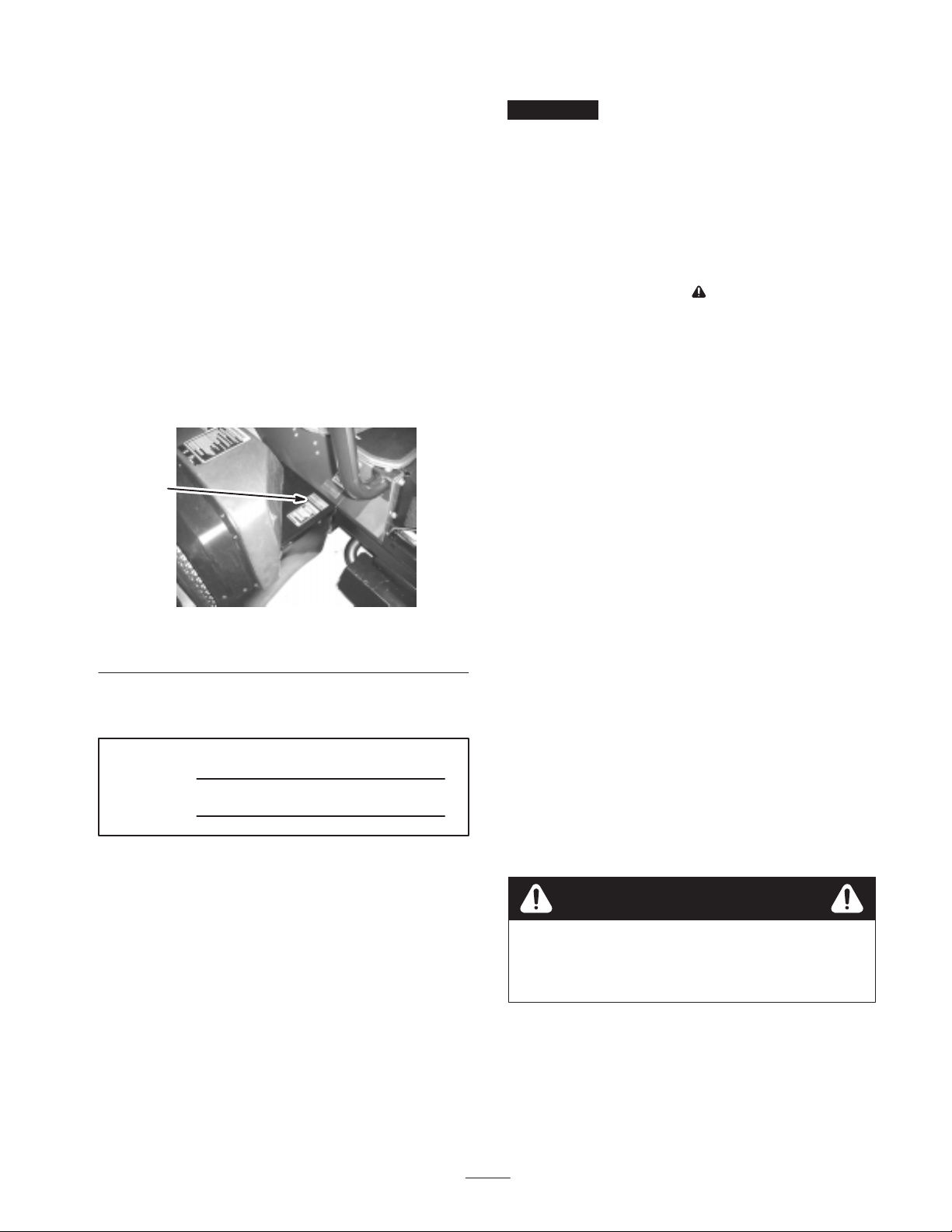
Whenever you need service, genuine Toro parts, or
additional information, contact an Authorized Service
Dealer or Toro Customer Service and have the model and
serial numbers of your product ready. Figure 1 illustrates
the location of the model and serial numbers on the
product.
This manual uses two other words to highlight information.
Important calls attention to special mechanical
information and Note: emphasizes general information
worthy of special attention.
Safety
Improper use or maintenance by the operator or owner
can result in injury. To reduce the potential for injury,
comply with these safety instructions and always pay
attention to the safety alert symbol, which means
CAUTION, WARNING, or DANGER—“personal
safety instruction.” Failure to comply with the
instruction may result in personal injury or death.
Supervisors, operators, and service persons should be
familiar with the following standards and publications:
(The material may be obtained from the addresses shown).
• Flammable and Combustible Liquids Code:
ANSI/NFPA 30
1
Figure 1
1. Location of the model and serial numbers
Write the product model and serial numbers in the space
below:
Model No.
Serial No.
This manual identifies potential hazards and has special
safety messages that help you and others avoid personal
injury and even death. Danger, Warning, and Caution are
signal words used to identify the level of hazard. However,
regardless of the hazard, be extremely careful.
Danger signals an extreme hazard that will cause serious
injury or death if you do not follow the recommended
precautions.
• National Fire Protection Association:
ANSI/NFPA #505; Powered Industrial Trucks
National Fire Prevention Association
Barrymarch Park
Quincy, Massachusetts 02269 U.S.A.
• ANSI/ASME B56.8 Personal Burden Carriers
American National Standards Institute, Inc.
1430 Broadway
New York, New York 10018 U.S.A.
• ANSI/UL 558; Internal Combustion Engine Powered
Industrial Trucks
American National Standards Institute, Inc.
1430 Broadway
New York, New York 10018 U.S.A.
or
Underwriters Laboratories
333 Pfingsten Road
Northbrook, Illinois 60062 U.S.A.
Safe Operating Practices
Warning
The sprayer is an off-highway vehicle only and is
not designed, equipped, or manufactured for use
on public streets, roads, or highways.
Warning signals a hazard that may cause serious injury or
death if you do not follow the recommended precautions.
Caution signals a hazard that may cause minor or moderate
injury if you do not follow the recommended precautions.
3
Page 4

Supervisor ’s Responsibilities
• Make sure that operators are thoroughly trained and
familiar with the Operator’s Manual, Engine Manual,
and all labels on the sprayer.
• Establish your own special procedures and work rules
for unusual operating conditions (e.g. slopes too steep
for sprayer operation).
Chemical Safety
Warning
Chemicals are hazardous and can injure you,
bystanders, animals, plants, soils, or other
property.
• Carefully read and follow the chemical
manufacturer’s instructions for the safe
preparation, use, and disposal of the chemical.
• Keep chemicals off of your or bystander’s skin.
if contact should occur, wash it off immediately
with clean water and detergent.
• Wear goggles and other protective equipment as
instructed by the chemical manufacturer.
• Never allow children to operate the sprayer. Anyone
who operates the sprayer should have a motor vehicle
license.
• Never allow other adults to operate the sprayer without
first reading and understanding the Operator’s Manual.
Only trained and authorized persons should operate this
sprayer. Make sure that all operators are physically and
mentally capable of operating the sprayer.
• This sprayer is designed to carry only you, the operator,
and one passenger in the seat provided by the
manufacturer. Never carry any other passengers on the
sprayer.
• Never operate the sprayer when under the influence of
drugs or alcohol. Even prescription drugs and cold
medicines can cause drowsiness.
• Do not drive the sprayer when you are tired. Be sure to
take occasional breaks. It is very important that you stay
alert at all times.
• Become familiar with the controls and know how to
stop the engine quickly.
• Keep all shields, safety devices, and decals in place. If a
shield, safety device, or decal is malfunctioning,
illegible, or damaged, repair or replace it before
operating the machine.
• Obtain proper training before using or handling
chemicals.
• Use the correct chemical for the job.
• Follow the chemical manufacturer’s instructions for the
safe application of the chemical.
• Handle chemicals in a well ventilated area.
• Wear goggles and other protective equipment as
instructed by the chemical manufacturer. Ensure that as
little skin as possible is exposed while using chemicals.
• Have clean water available especially when filling the
spray tank.
• Do not eat, drink, or smoke while working with
chemicals.
• Always wash your hands and other exposed areas as
soon as possible after finishing the work.
• Properly dispose of unused chemicals and chemical
containers as instructed by the chemical manufacturer
and your local codes.
• Chemicals and fumes in the tanks are dangerous; never
enter the tank or place your head over or in the opening.
• Always wear substantial shoes. Do not operate the
machine while wearing sandals, tennis shoes, or
sneakers. Do not wear loose fitting clothing or jewelry
which could get caught in moving parts and cause
personal injury.
• Wearing safety glasses, safety shoes, long pants, and a
helmet is advisable and required by some local safety
and insurance regulations.
• Avoid driving when it is dark, especially in unfamiliar
areas. If you must drive when it is dark, be sure to drive
cautiously, use the headlights, and even consider adding
additional lights.
• Be extremely careful when operating around people.
Always be aware of where bystanders might be.
• Before operating the sprayer, always check the
designated areas of the sprayer that are stated in the
Pre-Starting section of this manual, page 17. If
something is wrong, do not use the sprayer. Make sure
that the problem is corrected before the sprayer or
attachment is operated.
• Ensure that all fluid line connectors are tight and all
hoses are in good condition before applying pressure to
the system.
Before Operating
• Operate the machine only after reading and
understanding the contents of this manual.
• Since gasoline is highly flammable, handle it carefully.
– Use an approved gasoline container.
– Do not remove the cap from the fuel tank when the
engine is hot or running.
4
Page 5

– Do not smoke while handling gasoline.
– Fill the fuel tank outdoors, and fill it to about 1 inch
(25 mm) below the top of the tank (the bottom of
the filler neck). Do not overfill it.
– Wipe up any spilled gasoline.
– Watch out for traffic when you are near or crossing
roads. Always yield the right of way to pedestrians
and other vehicles. This sprayer is not designed for
use on streets or highways. Always signal your turns
or stop early enough so that other people know what
you plan to do. Obey all traffic rules and
regulations.
While Operating
Warning
Engine exhaust contains carbon monoxide, which
is an odorless, deadly poison that can kill you.
Do not run engine indoors or in an enclosed area.
• The operator and passenger should remain seated
whenever the sprayer is in motion. The operator should
keep both hands on the steering wheel whenever
possible, and the passenger should use the hand holds
provided. Keep your arms and legs within the sprayer
body at all times.
• Drive slower and turn less sharply when you are
carrying a passenger. Remember your passenger may
not be expecting you to brake or turn and may not be
ready.
• Always watch out for and avoid low overhangs such as
tree limbs, door jambs, and over-head walkways. Make
sure there is enough room over head to easily clear the
sprayer and your head.
• Failure to operate the sprayer safely may result in an
accident, tip over of the sprayer, and serious injury or
death. Drive carefully. To prevent tipping or loss of
control:
– Use extreme caution, reduce speed, and maintain a
safe distance around sand traps, ditches, creeks,
ramps, unfamiliar areas, or any areas that have
abrupt changes in ground conditions or elevation.
– Watch for holes or other hidden hazards.
– Use extra caution when operating the sprayer on wet
surfaces, in adverse weather conditions, at higher
speeds, or with a full load. Stopping time and
distance will increase with a full load.
– Avoid sudden stops and starts. Do not go from
reverse to forward or forward to reverse without
first coming to a complete stop.
– Slow down before turning. Do not attempt sharp
turns or abrupt maneuvers or other unsafe driving
actions that may cause a loss of sprayer control.
– Before backing up, look to the rear and ensure that
no one is behind you. Back up slowly.
– The electrical and exhaust systems of the sprayer
can produce sparks capable of igniting explosive
materials. Never operate the sprayer in or near an
area where there is dust or fumes in the air which
are explosive.
– If you are ever unsure about safe operation, stop
work and ask your supervisor.
• Do not touch the engine or muffler while the engine is
running or soon after it has stopped. These areas may be
hot enough to cause burns.
• If the machine ever vibrates abnormally, stop
immediately, wait for all motion to stop, and inspect the
sprayer for damage. Repair all damage before resuming
operation.
• Before getting off of the seat:
A. Stop the movement of the machine.
B. Place the range selector in Neutral and set the
parking brake.
C. Turn the ignition key to Off.
D. Remove the ignition key.
Note: If the sprayer is stopped on an incline, block the
wheels after getting off the sprayer.
Braking
• Slow down before you approach an obstacle. This gives
you extra time to stop or turn away. Hitting an obstacle
can damage the sprayer and its contents. More
important, it can injure you and your passenger.
• Gross Vehicle Weight (GVW) has a major impact on
your ability to stop and/or turn. Heavy loads and
attachments make a sprayer harder to stop or turn. The
heavier the load, the longer it takes to stop.
• Turf and pavement are much slipperier when they are
wet. It can take 2 to 4 times as long to stop on wet
surfaces as on dry surfaces. If you drive through
standing water deep enough to get the brakes wet, they
will not work well until they are dry. After driving
through water, you should test the brakes to make sure
they work properly. If they do not, drive slowly while
putting light pressure on the brake pedal. This will dry
the brakes out.
• When operating with a liquid in the tank, reduce your
speed and allow for sufficient braking distance. Do not
suddenly apply the brakes. Use extra caution on slopes.
5
Page 6

• Be aware that heavy loads increase your stopping
distance and reduce your ability to turn quickly without
tipping over.
• Before servicing or making adjustments to the machine,
stop the engine, set the parking brake, and remove the
key from the ignition to prevent someone from
accidentally starting the engine.
Operating on Hills and Rough Terrain
Operating the sprayer on a hill may cause tipping or rolling
of the sprayer, or the engine may stall and you could lose
headway on the hill. This could result in personal injury.
• Do not accelerate quickly or slam on the brakes when
backing down a hill, especially with liquid in the tank.
• Never drive across a steep hill; always drive straight up
or down or go around the hill.
• If the engine stalls or you begin to lose headway while
climbing a hill, gradually apply the brakes and slowly
back straight down the hill.
• Turning while traveling up or down hills can be
dangerous. If you have to turn while on a hill, do it
slowly and cautiously. Never make sharp or fast turns.
• Avoid stopping on hills, especially with liquid in the
tank. Stopping while going down a hill will take longer
than stopping on level ground. If the sprayer must be
stopped, avoid sudden speed changes, which may
initiate tipping or rolling of the sprayer. Do not slam on
the brakes when rolling backward, as this may cause the
sprayer to overturn.
• The Toro Company strongly recommends installing the
optional ROPS Kit when operating on hilly terrain. If
you install a ROPS, always wear the seat belt when
driving the sprayer.
• Liquid loads will shift when turning, going up or down
hills, suddenly changing speeds, or while driving over
rough surfaces. Shifting loads can cause the sprayer to
tip over. Reduce your speed in these conditions.
Warning
Sudden changes in terrain may cause abrupt
steering wheel movement, possibly resulting in
hand and arm injuries.
• To make sure that the entire machine is in good
condition, keep all nuts, bolts, and screws properly
tightened.
• To reduce the potential for fire, keep the engine area
free of excessive grease, grass, leaves, and
accumulation of dirt.
• Never use an open flame to check the level or leakage
of fuel or battery electrolyte.
• If the engine must be running to perform a maintenance
adjustment, keep your hands, feet, clothing, and any
parts of your body away from the engine and any
moving parts. Keep everyone away.
• Do not use open pans of fuel or flammable cleaning
fluids when cleaning parts.
• Do not adjust the ground speed governor. To ensure
safety and accuracy, have an Authorized Toro
Distributor check the ground speed.
• Keep your body and hands away from pin hole leaks or
nozzles that eject high pressure fluid. Use cardboard or
paper to find leaks. Fluid escaping under pressure can
penetrate skin and cause injury requiring surgery within
a few hours by a qualified surgeon or gangrene may
result.
• If major repairs are ever needed or assistance is
required, contact an Authorized Toro Distributor.
• To be sure of optimum performance and safety, always
purchase genuine Toro replacement parts and
accessories. Replacement parts and accessories made by
other manufacturers could be dangerous. Altering this
sprayer in any manner that may affect sprayer
operation, performance, durability, and may result in
injury or death. Such use could void the product
warranty.
• Reduce your speed when operating on rough
terrain and near curbs.
• Grip the steering wheel loosely around the
perimeter. Keep your hands clear of the steering
wheel spokes.
Maintenance
• Only permit qualified and authorized personnel to
maintain, repair, adjust, or inspect the sprayer.
6
Page 7
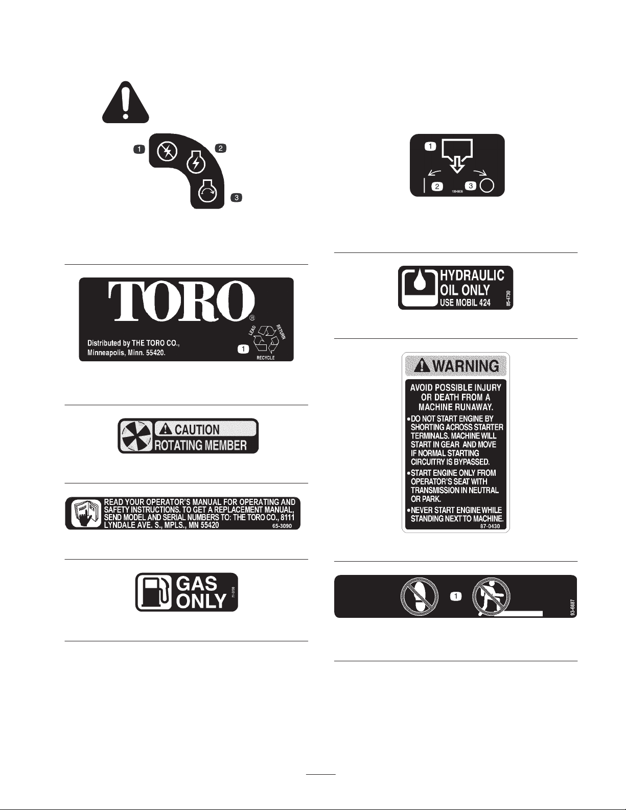
Safety and Instruction Decals
Safety decals and instructions are easily visible to the operator and are located near any area
of potential danger. Replace any decal that is damaged or lost.
41176
1. No power
2. Engine—ignition
3. Engine—start
1. Tank drain
2. On
100-6836
3. Off
85-4730
1. Recycle
26-7170
54-0890
65-3090
71-3730
87-0430
93-6687
1. Do not step here.
7
Page 8
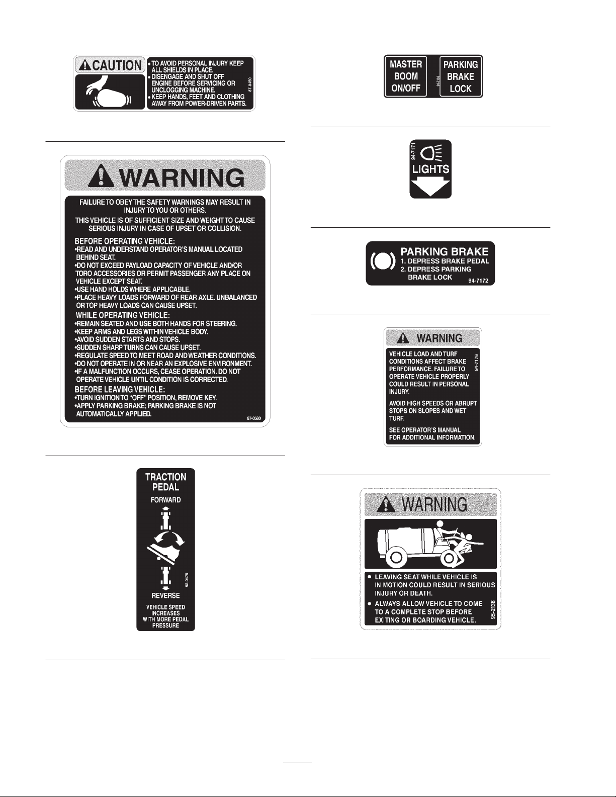
87-0450
94-7132
94-7171
94-7172
87-0580
92-0479
94-7176
95-2136
8
Page 9
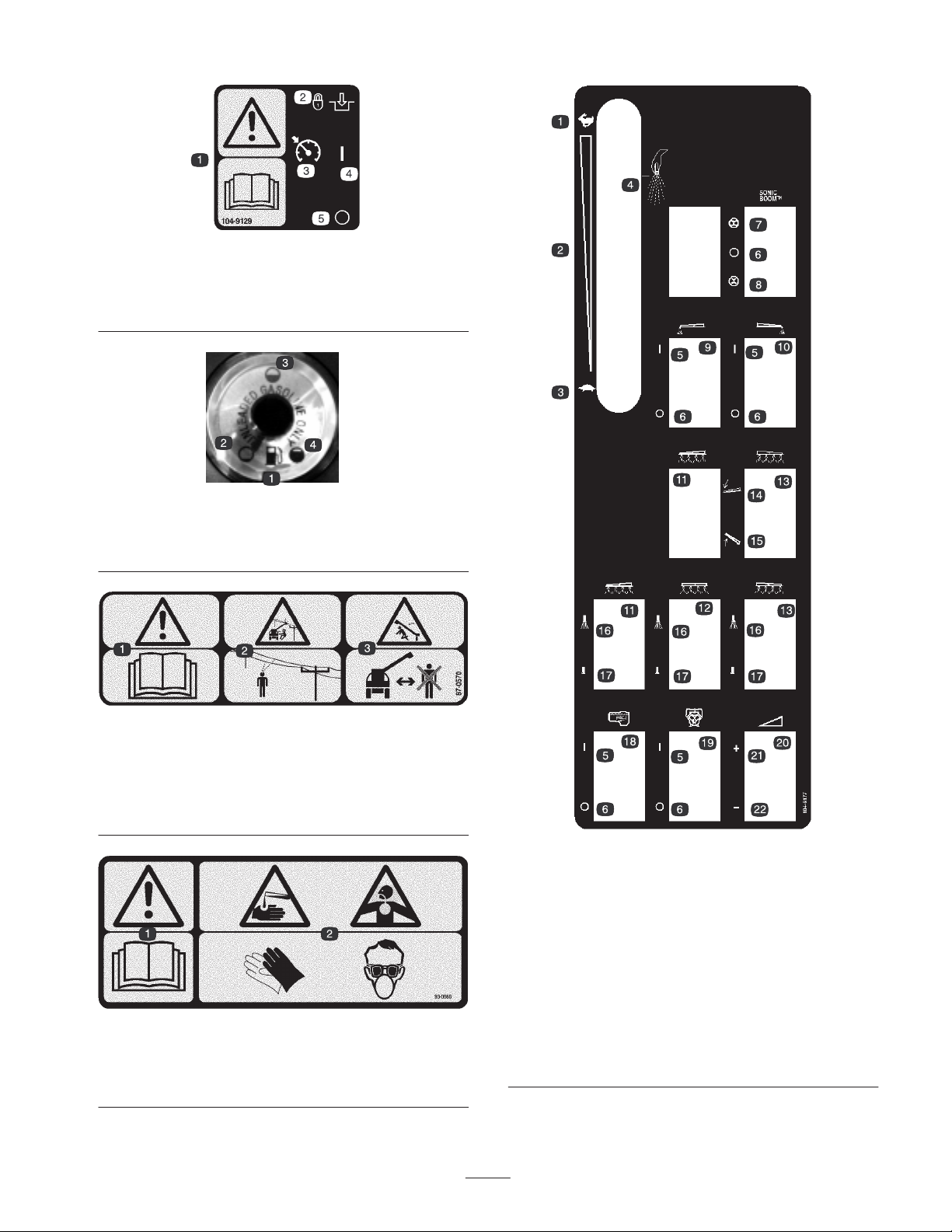
1. Warning—read the
Operator’s Manual
2. Lock and engage
1. Fuel
2. Empty
.
104-9129
3. Cruise control
4. On
5. Off
100-8386
3. Half-full
4. Full
87-0570
1. Warning—read the
2. Electric shock hazard, overhead power lines—watch for
overhead power lines.
3. Crushing hazard, boom—keep bystanders a safe distance from
the machine.
Operator’s Manual.
93-0688
1. Warning—read the
2. Caustic liquid/chemical burn and toxic gas inhalation
hazards—wear hand, skin, eye, and respiratory protection.
Operator’s Manual.
1. Fast
2. Continuous variable
setting
3. Slow
4. Spray
5. On
6. Off
7. Automatic
8. Manual
9. Left boom foam marker
10. Right boom foam marker
11. Left boom
104-9177
12. Center boom
13. Right boom
14. Lower the boom.
15. Raise the boom.
16. Spray on
17. Spray off
18. Agitation
19. Pump
20. Continuous variable
setting, spray pressure
21. Increase
22. Decrease
9
Page 10
Specifications
Note: Specifications and design are subject to change
without notice.
Base weight 1750 lb (794 kg)
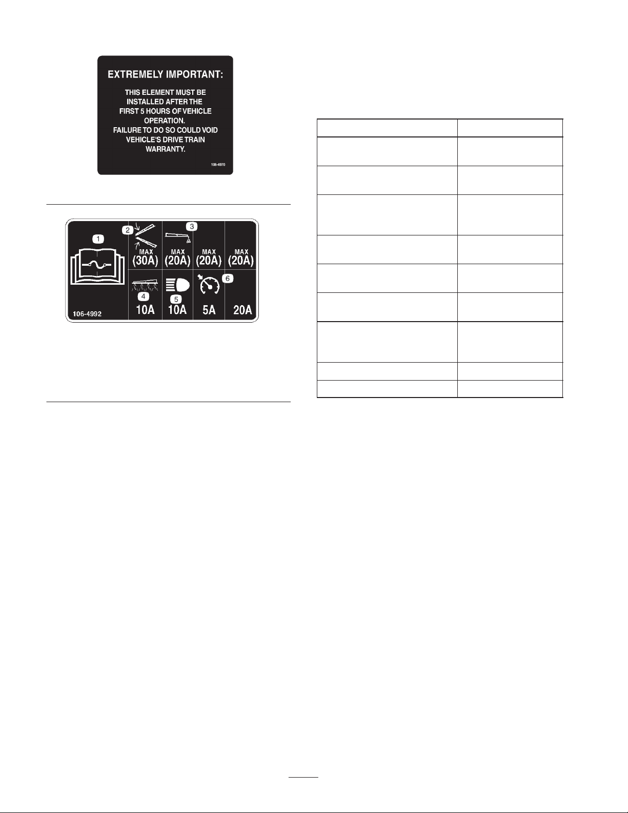
1. Read the
Manual
fuses.
2. Boom lift
Operator’s
for information on
106-4970
106-4992
3. Foam marker
4. Spray system
5. Headlights
6. Cruise control
Weight with standard spray
system, empty, with operator
Weight with standard spray
system, full, with operator
Maximum gross vehicle
weight (GVW)
(on level ground)
Tank capacity 300 US gallons
Overall width with standard
spray system
Overall length with standard
spray system
Overall height with standard
spray system to the top of
the tank
Ground clearance 6.5 inches (16.5 cm)
Wheel base 78 inches (198 cm)
2540 lb (1152.6 kg)
5040 lb (2287 kg)
6040 lb (2741 kg)
(1135.6 L)
72 inches (183 cm)
136 inches (345 cm)
57.5 inches (146 cm)
Optional Equipment
The Toro Company has optional equipment and accessories
that you can purchase separately and install on your
sprayer. Contact your Authorized Service Dealer for a
complete list of optional equipment that is currently
available for your sprayer.
10
Page 11
Setup
Note: Determine the left and right sides of the machine from the normal operating position.
To use the sprayer, you must obtain and install a boom kit and nozzles. Contact your Authorized Toro Distributor for
information on the available boom kits and accessories. After you install your booms and nozzles and before using the
sprayer for the first time, adjust the boom bypass valves so that the pressure and application rate remains the same for all
booms when you turn one or more booms off. Refer to Adjusting the Boom Bypass valves, page 20.
Caution
Without a boom kit installed, the sprayer may spray chemicals out of the boom valves, possibly
injuring bystanders or causing property damage.
Do not operate the sprayer without a boom kit and nozzles installed.
Loose Parts
Note: Use the chart below to verify that all parts have been shipped.
Description Qty. Use
90 degree fitting
Quick coupler
Hose adapter
Fill receptacle bracket
Flange nut, 5/16 inch
Hairpin cotters
Key 2 Use in the ignition switch.
Operator’s Manual
Engine Operator’s Manual
Operator Video 1 Watch before operating the machine.
Parts Catalog 1 Use for ordering replacement parts.
Registration Card 1 Complete and return to Toro.
Predelivery Inspection Form 1 Complete and file in your customer history portfolio.
1
1
1
1
1
2
1
1
Install the anti-siphon fill receptacle.
Read before operating the machine.
11
Page 12
Installing the Anti-siphon Fill
Receptacle
1. Remove the rubber cap from the stud on the tank strap
(Fig. 2).
5
4
1
6
2. Remove the dipstick, located under the passenger seat,
and wipe it with a clean rag (Fig. 3). Insert the dipstick
into the tube and make sure it is seated fully. Remove
the dipstick and check the oil level.
1
3
2
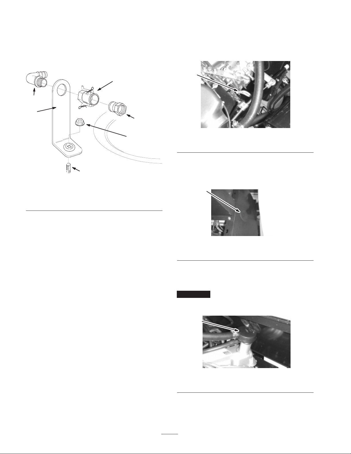
Figure 2
1. Fill receptacle bracket
2. Stud
3. Flange nut, 5/16 inch
2. Place the fill receptacle bracket over the stud and secure
it with a flange nut (5/16 inch) (Fig. 2).
3. Place the threaded end of the 90 degree elbow fitting
through the bracket and thread the quick coupler onto it,
securing it to the bracket (Fig. 2).
Note: Install the elbow fitting with the open end pointing
toward the tank opening so the water will arc into the tank
when you fill it.
4. Install the hose adapter into the quick coupler (Fig. 2).
5. Lock the adapter into place by swinging the levers
toward the adapter and then secure them with the
hairpin cotters.
4. 90 degree elbow fitting
5. Quick coupler
6. Hose adapter
1865
Figure 3
1. Dipstick
3. If the oil level is low, add oil as follows:
A. Remove the access plug in the wall behind the
engine (Fig. 4).
1
Figure 4
1. Oil access plug
B. Remove the filler cap from the valve cover (Fig. 5)
and pour oil into the opening until the oil level is up
to the Full mark on the dipstick.
Important Refer to Servicing Engine Oil, page 26, for
the proper oil type and viscosity. Add the oil slowly and
check the level often during this process. Do not overfill.
Before Operating
Checking the Engine Oil
The engine is shipped with oil in the crankcase; however,
the level of oil must be checked before you first start the
engine and after you have run it.
1. Position the sprayer on a level surface, set the parking
brake, stop the pump, stop the engine, and remove the
ignition key.
1
Figure 5
1. Oil filler cap
C. Install the filler cap and access plug.
4. Install the dipstick firmly in place.
12
Page 13
Checking the Tire Pressure
Check the tire pressure every 8 hours or daily to ensure
proper levels. Fill the tires to 18 psi (124 kPa). Also, check
the tires for wear or damage.
Filling the Fuel Tank
The fuel tank capacity is approximately 10.6 US gallons
(40 L).
Note: The fuel tank cap contains a gauge which shows the
fuel level; check it frequently.
Adding Fuel
Danger
In certain conditions, gasoline is extremely
flammable and highly explosive. A fire or
explosion from gasoline can burn you and others
and can damage property.
• Fill the fuel tank outdoors, in an open area,
when the engine is cold. Wipe up any gasoline
that spills.
• Do not fill the fuel tank completely full. Add
gasoline to the fuel tank until the level is 1 inch
(25 mm) below the bottom of the filler neck.
This empty space in the tank allows gasoline to
expand.
• Never smoke when handling gasoline and stay
away from an open flame or where gasoline
fumes may be ignited by a spark.
• Store gasoline in an approved container and
keep it out of the reach of children. Never buy
more than a 30-day supply of gasoline.
• Always place gasoline containers on the ground
away from your sprayer before filling.
• Do not fill gasoline containers inside a vehicle or
on a truck or trailer bed because interior
carpets or plastic truck bed liners may insulate
the container and slow the loss of any static
charge.
• When practical, remove gas-powered equipment
from the truck or trailer and refuel the
equipment with its wheels on the ground.
• If this is not possible, then refuel such
equipment on a truck or trailer from a portable
container, rather than from a gasoline dispenser
nozzle.
• If a gasoline dispenser nozzle must be used, keep
the nozzle in contact with the rim of the fuel
tank or container opening at all times until
fueling is complete.
Recommended Gasoline
1. Position the sprayer on a level surface, set the parking
brake, stop the pump, stop the engine, remove the
ignition key, and allow the engine to cool.
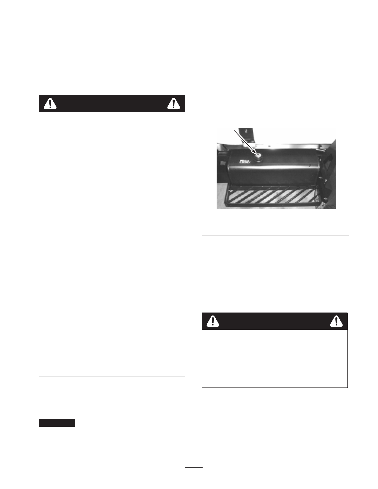
2. Clean the area around the fuel tank cap and remove it
(Fig. 6).
1
Figure 6
1. Fuel tank cap
3. Fill the tank to about one inch below the top of the tank,
(bottom of the filler neck). This space in the tank allows
gasoline to expand. Do not overfill.
4. Install the fuel tank cap securely.
5. Wipe up any fuel that may have spilled.
Checking the Coolant Level
Caution
If the engine has been running, the coolant may be
hot and pressurized. If you open the radiator cap
when the coolant is hot, it could spray out and
severely burn you or bystanders.
Allow the engine to cool for at least 15 minutes
before opening the radiator cap.
Use fresh, clean, unleaded regular gasoline suitable for
automotive use (87 pump octane minimum). Leaded
gasoline may be used if unleaded regular is not available.
Important Never use gasoline containing methanol,
gasoline containing more than 10% ethanol, gasoline
additives, or white gas because engine fuel system damage
could result.
1. Position the sprayer on a level surface, set the parking
brake, stop the pump, stop the engine, and remove the
ignition key.
2. When the engine is cool, remove the radiator cap
(Fig. 7) and check the coolant level.
13
Page 14

The coolant should be 3/4 to 1-1/2 inches (2 to 4 cm)
below the bottom of the filler neck.
1
Figure 7
1. Radiator cap
3. If the coolant is low, add a solution of 50% water and
50% permanent ethylene glycol antifreeze.
Checking the Brakes
Before starting the sprayer, lightly press the brake pedal. If
the pedal travels more than 1 inch (2.5 cm) before you feel
resistance, adjust the brakes; refer to Adjusting the Brakes,
page 33.
Warning
If you operate the sprayer with poorly adjusted or
worn brakes you could lose control of the sprayer,
resulting in serious injury or death to you or
bystanders.
Always check the brakes before operating the
sprayer and keep them properly adjusted and
repaired.
Important Do not use water only or an
alcohol/methanol based coolant.
4. Install and secure the radiator cap.
Checking the Hydraulic Fluid
1. Position the sprayer on a level surface, set the parking
brake, stop the pump, stop the engine, and remove the
ignition key.
2. Clean the area around the hydraulic oil tank cap and
remove it (Fig. 8).
Important Be very careful not to get dirt or other
contaminants into the opening when checking the oil.
2
Filling the Fresh Water Tank
The sprayer is equipped with a fresh water tank (Fig. 9) for
washing chemicals off of your skin, eyes, or other surfaces
in the case of accidental exposure. Always fill the fresh
water tank with clean water before handling or mixing any
chemicals.
1
2
3
Figure 9
1. Filler cap
2. Fresh water tank
3. Spigot
Figure 8
1. Hydraulic oil tank cap
3. Check the oil level by looking into the opening.
The oil should be 2 inches (5 cm) below the bottom of
the filler neck.
4. If the oil is low, fill the tank with Mobil 424
(Mobil 15M) hydraulic fluid or equivalent.
5. Install and secure the hydraulic oil tank cap.
To open the fresh water tank spigot, turn the lever on the
spigot toward the front of the sprayer.
14
Page 15

Operation
Note: Determine the left and right sides of the machine
from the normal operating position.
Think Safety First
Please carefully read all of the safety instructions and
decals in the safety section. Knowing this information
could help you or bystanders avoid injury.
Vehicle Controls
Traction Pedal
The traction pedal (Fig. 10) controls the movement of the
machine, both forward and reverse. Using the heel and tow
of the right foot, press the top of the pedal to move forward
or the bottom of the pedal to move in reverse. Release the
pedal to slow and stop.
Important Ensure that you allow the sprayer to come
to a stop before switching between Forward and Reverse.
2
Brake Pedal
Use the brake pedal to stop or slow the sprayer (Fig. 10).
Warning
If you operate the sprayer with poorly adjusted or
worn brakes you could lose control of the sprayer,
resulting in serious injury or death to you or
bystanders.
Always check the brakes before operating the
sprayer and keep them properly adjusted and
repaired.
Parking Brake
The parking brake is a pedal to the left of the brake
(Fig. 10). Engage the parking brake whenever you plan on
leaving the seat to prevent accidental movement of the
sprayer. To engage the parking brake, press the brake pedal
and, while holding the brake, press the parking brake pedal.
To disengage, press and release the brake pedal. If the
sprayer is parked on a steep grade, apply the parking brake
and place blocks at the downhill side of the wheels.
3
Figure 10
1. Traction pedal
2. Brake pedal
The further you press the pedal in either direction, the
faster the sprayer will travel. To obtain maximum forward
speed, set the throttle lever to the Fast position and press
the traction pedal all the way forward.
To obtain maximum power with a full tank or when
traveling up a hill, set the throttle lever in the Fast position
and drive slowly so that the engine remains at a high rpm.
3. Parking brake pedal
1
Choke Control
The choke control is a small knob between the seats under
the control panel (Fig. 11). To start a cold engine, pull the
choke control out. After the engine starts, regulate the
choke to keep the engine running smoothly. As soon as
possible, push the control in. A warm engine requires little
or no choking.
1
Figure 11
1. Choke control
Throttle Lever
The throttle lever, located on the control panel between the
seats (Fig. 12), controls the speed of the engine. Push the
lever forward to increase the engine speed and pull it
rearward to decrease engine speed. Use the Spray position
when spraying for optimal results.
15
Page 16

1
2
Figure 12
1. Throttle lever 2. Spray position
3. Take your foot off of the traction pedal.
The sprayer will maintain the speed you set.
To release the cruise control, do one of the following:
• Press the top of the cruise control switch.
• Press the brake pedal.
The light on the switch turns off and the traction control
returns to the traction pedal.
Caution
Ignition Switch
The ignition switch (Fig. 13), used to start and stop the
engine, has 3 positions: Stop, Run, and Start. Rotate the key
clockwise to the Start position to start the engine and
release it to the Run position when started. Rotate the key
to the Stop position to stop the engine.
1
4
3
2
Figure 13
1. Pressure gauge
2. Ignition switch
3. Cruise control switch
4. Headlight switch
Pressure Gauge
If you press the switch to turn off the cruise
control and do not have your foot on the traction
pedal, the traction unit may come to a sudden stop
and cause you to lose control, possibly injuring you
or bystanders.
Ensure that you have you foot on the traction
pedal when you disengage the cruise control using
the switch.
Headlight Switch
Toggle the switch to operate the headlights (Fig. 13). Push
it forward to turn the lights on and rearward to turn them
off.
Hour Meter
The hour meter (Fig. 11) indicates the total number of
hours the engine has run. The hour meter starts to function
whenever the key is turned to the Run position.
2
3
1
The pressure gauge (Fig. 13) indicates the pressure of the
spray system. Refer to Pressure Gauge, page 20, for more
information.
Cruise Control Switch
The cruise control switch (Fig. 13) sets the forward speed
of the sprayer and holds it without pressure on the traction
pedal. Set the cruise control and maintain a speed as
follows:
1. Drive forward and attain the speed you desire; refer to
Driving the Sprayer, page 17.
2. Press the top of the cruise control switch.
The light on the switch illuminates.
Figure 14
1. Hour meter
2. Voltmeter
3. Engine oil pressure light
4. Coolant temperature
gauge
Voltmeter
The voltmeter (Fig. 14) indicates the level of charge in the
battery. When the battery is fully charged, the voltmeter
will read in the center of the dial when the key is in the Run
position with the engine off. When the engine is running
the voltmeter needle should be to the right.
16
4
Page 17

Engine Oil Pressure Warning Light
The engine oil pressure warning light (Fig. 14) illuminates
when the engine oil pressure is dangerously low. If the light
illuminates, stop the engine immediately and correct the
problem before starting the engine again.
Coolant Temperature Gauge
The coolant temperature gauge (Fig. 14) indicates the
temperature of the coolant. This gauge only functions when
the ignition key is in the Run position. When the engine is
running the gauge needle should advance to and remain in
the green range of the dial.
Note: These tires are different than car tires; they
require less pressure to minimize turf compaction and
damage.
• Check all fluid levels and add the appropriate amount of
specified fluids, if any are found to be low.
• Check the brake pedal operation.
• Ensure that the lights are working.
• Turn the steering wheel to the left and right to check
steering response.
• With the engine off, check for oil leaks, loose parts, and
any other noticeable malfunctions.
If the needle enters the red range, the engine is over
heating. Stop the sprayer and allow the engine to idle in
neutral for 2 minutes, then stop the engine, allow it to cool,
and determine the cause of the overheating.
Caution
If the engine has been running, the coolant may be
hot and pressurized. If you open the radiator cap
when the coolant is hot, it could spray out and
severely burn you or bystanders.
Allow the engine to cool for at least 15 minutes
before opening the radiator cap.
Fuel Gauge
The fuel gauge (Fig. 15) shows the amount of fuel in the
tank.
1
If any of the above items are not correct, notify your
mechanic or check with your supervisor before taking the
sprayer out for the day. Your supervisor may want you to
check other items on a daily basis, so ask what your
responsibilities are.
Starting the Engine
1. Sit in the operator’s seat, insert the key into the ignition
switch, and rotate the key clockwise to the Run
position.
2. Press the brake.
3. Ensure that the pump switch is in the Off position.
4. Move the throttle to the Slow position.
5. If the engine is cold, pull the choke knob.
Important Do not use the choke if the engine is warm.
6. Turn the key to the Start position until the engine starts.
Important Do not hold the key in the Start position for
more than 10 seconds. If the engine has not started after 10
seconds, wait 1 minute before trying again. Do not attempt
to push or tow the sprayer to start the engine.
Figure 15
1. Fuel gauge
Pre-Starting Checks
Check the following items each time you begin using the
sprayer for the day:
• Check the tire pressure.
7. Once the engine starts, push the choke knob in slowly.
8. Adjust the throttle as needed.
Driving the Sprayer
1. Press the traction pedal forward to drive forward or
rearward to drive in reverse.
Important Ensure that you allow the sprayer to come
to a stop before switching between Forward and Reverse.
2. To slowly stop the sprayer, release the traction pedal.
3. To stop quickly, press the brake pedal.
Note: Stopping distance may vary depending on the
sprayer load and speed.
17
Page 18

Stopping the Engine
1. Press the brake to stop the sprayer.
2. With the brake pressed, press the parking brake pedal to
lock the brake.
3. Move the throttle lever to the Slow position.
4. Turn the ignition key to the Stop position.
5. Remove the key from the switch to prevent someone
from accidentally starting the engine.
New Sprayer Break-In
To provide proper performance and long sprayer life,
follow these guidelines for the first 100 operating hours:
• Check the fluid and engine oil levels regularly and be
alert for indications of overheating in any component of
the sprayer.
• After starting a cold engine, let it warm up for about
15 seconds before accelerating.
• Avoid hard braking situations for the first several hours
of new sprayer break-in operation. New brake linings
may not be at optimum performance until several hours
of use has caused the brakes to become burnished
(broken-in).
• Avoid racing the engine.
• Vary the sprayer speed during operation. Avoid fast
starts and quick stops.
• Refer to the Maintenance section for any special low
hour checks.
Transporting the Sprayer
For moving the sprayer long distances, use a trailer. Secure
the sprayer to the trailer. Figures 16 and 17 illustrate the
tie-down points.
1
Figure 17
1. Front tie down points
1
Towing the Sprayer
In case of an emergency, the sprayer can be towed for a
short distance after you open the tow valve. However, we
do not recommend this as a standard procedure.
Warning
Towing at excessive speeds could cause a loss of
steering control, resulting in personal injury.
Never tow the sprayer faster than 3 mph (4.8 kph).
Towing the sprayer is a two person job. If the machine must
be moved a considerable distance, transport it on a truck or
trailer; refer to Transporting the sprayer, page 18.
1. Rotate the tow valve (Fig. 18) 90 degrees in either
direction to open it.
Important If you do not open the tow valve before
towing the sprayer you will damage the transmission.
1. Rear tie down point
1
Figure 16
1
Figure 18
1. Tow valve
2. Affix a tow line to the frame.
18
Page 19

3. Release the parking brake.
4. Tow the sprayer at less than 3 mph (4.8 kph).
5. When finished, close the tow valve and torque it to no
more than 5 to 8 ft-lb (7 to 11 N⋅m).
Pump Switch
The pump switch is located on the control panel to the right
of the seat (Fig. 20). Toggle this switch forward to run the
pump or rearward to stop the pump. When the switch is
turned on, a light on the switch illuminates.
Sprayer Controls and
Components
Master Boom Switch
The master boom switch allows you to start or stop the
spray operation. Press the switch with your foot to enable
or disable the spray system (Fig. 19).
1
Figure 19
1. Master boom switch
Boom Switches
The boom switches are located at the front of the control
panel to the right of the seat (Fig. 20). Toggle each switch
forward to turn the corresponding boom section on and
rearward to turn each off. When the switch is turned on, a
light on the switch illuminates. These switches will only
affect the spray system when the master boom switch is on.
2
4
Application Rate Switch
The application rate switch is located on the control panel
to the right of the seat (Fig. 20). Press and hold the switch
forward to increase the spray system pressure, or press and
hold it rearward to decrease pressure.
Agitation Switch
The agitation switch is located on the control panel to the
right of the seat (Fig. 20). Toggle this switch forward to
turn agitation in the tank on or rearward to stop the
agitation. When the switch is turned on, a light on the
switch illuminates. For agitation to work, the pump must be
on and the engine must be running above an idle. The
agitation valve is located behind the tank (Fig. 21).
Boom Lift, Sonic Boom, and Foam Marker
Switch Locations
If you install the electric boom lift, sonic boom, and foam
marker kit, you will add switches to the control panel for
controlling their operation. The sprayer comes with plastic
plugs in these locations.
Boom Valves
These valves turn the three booms on or off (Fig. 21). If
you ever need to manually turn off a boom, rotate the knob
on the valve clockwise to turn the valve off or
counterclockwise to turn it on.
3
1
5
1. Boom switches
2. Pump switch
3. Application rate switch
4. Agitation switch
Figure 20
5. Empty plugs (picture
shows the optional boom
lift switches installed)
1
Figure 21
1. Agitation valve 2. Boom valves
19
2
Page 20

Boom Bypass Valves
The boom bypass valves redirect the fluid flow for a boom
to the tank when you turn off the boom section. You can
adjust these valves to ensure that the boom pressure
remains constant no matter how many booms are on. Refer
to Adjusting the Boom Bypass Valves, page 20.
Pressure Gauge
The pressure gauge is located on the dash (Fig. 13). This
gauge shows the pressure of the fluid in the system in psi
and kPa.
Pump
The pump is located near the back of the tank on the left
side (Fig. 22).
1
2
1
1. Tank drain knob
2. Tank cover
3
Figure 23
3. Anti-siphon fill receptacle
2
Tank Cover
The tank cover is located in the center of the top of the tank
(Fig. 23). To open it, turn off the engine, then turn the front
half of the cover to the left and swing it open. You can
remove the strainer inside for cleaning. To seal the tank,
close the cover and rotate the front half toward the right.
Anti-siphon Fill Receptacle
To the front of the tank cover is a hose receptacle with a
threaded fitting and a 90 degree barbed fitting and tube
which you can direct toward the tank opening (Fig. 23).
This receptacle allows you to connect a water hose to it and
fill the tank with water without contaminating the hose with
the chemicals in the tank.
Figure 22
1. Pump 2. Grease fitting
Tank Drain Knob
The tank drain knob is located on top of the tank (Fig. 23).
Turn the knob counterclockwise to drain the tank.
Adjusting the Boom Bypass
Valves
Important If you have the Pro Control Spray System
installed, the boom valves must be closed.
After you install your booms and nozzles and before using
the sprayer for the first time, adjust the boom bypass valves
so that the pressure and application rate remains the same
for all booms when you turn one or more booms off.
Select an open flat area to perform this procedure.
1. Fill the spray tank with clean water.
2. Put the extension booms down, if installed.
3. Set the parking brake and start the engine .
4. Move the throttle lever to the Spray position.
5. Set the pump switch to the On position to start the
pump.
20
Page 21

6. Set all three boom switches and the master boom switch
to the On position.
Caution
7. Use the application rate switch to adjust the pressure as
read on the pressure gauge until it is in the range for the
nozzles you installed on the booms (typically 40 psi).
8. Record the reading on the pressure gauge.
9. Turn off one of the booms using the appropriate boom
switch.
10.Adjust the boom bypass valve (Fig. 24) under the boom
control valve for the boom you turned off until the
pressure reading on the gauge is the same as it was in
step 7.
1
Figure 24
1. Boomy bypass valves
11. Turn the boom on.
12.Repeat steps 9 through 11 for the other booms.
13.Drive the sprayer at the desired speed while spraying
and turn each boom off individually. The pressure on
the gauge should remain constant.
Operating the Sprayer
To operate the sprayer you first fill the spray tank, then
apply the solution to the work area, and finally clean the
tank. It is important that you complete all three of these
steps in succession to avoid damaging the sprayer. For
example, do not mix and add chemicals in the spray tank at
night and then spray in the morning. This would lead to
separation of the chemicals and possible damage to the
sprayer components.
Chemicals are hazardous and can cause personal
injury.
• Read the directions on the chemical labels
before handling the chemicals and follow all
manufacturer recommendations and
precautions.
• Keep chemicals away from your skin. Should
contact occur, wash the affected area thoroughly
with soap and clean water.
• Wear goggles and any other protective
equipment recommended by the chemical
manufacturer.
Filling the Spray Tank
Important Ensure that the chemicals you will be using
are compatible for use with Viton (see the manufacturer’s
label; it should indicate if it is not compatible). Using a
chemical that is not compatible with Viton will degrade the
o-rings in the sprayer, causing leaks.
1. Stop the sprayer on a level surface, stop the engine, and
set the parking brake.
2. Determine the amount of water needed to mix the
amount of chemical you need as prescribed by the
chemical manufacturer.
3. Open the lid on the spray tank.
4. Add 3/4 of the required water to the spray tank using
the anti-siphon fill receptacle.
Important Always use fresh clean water in the spray
tank. Do not pour concentrate into an empty tank.
5. Start the engine and move the throttle lever to the Spray
position.
6. Set the pump switch to the On position.
7. Set the agitation switch to the On position.
8. Add the proper amount of chemical concentrate to the
tank, as directed by the chemical manufacturer.
Important If you are using a wetable powder, mix the
powder with a small amount of water to form a slurry
before adding it to the tank
9. Add the remaining water to the tank.
21
Page 22

Applying Chemicals
Important In order to ensure that your solution remains
well mixed, use the agitation feature whenever you have
solution in the tank. For agitation to work, the pump must
be on and the engine must be running above an idle.
Note: This procedure assumes that the pump is on from the
Filling the Spray Tank procedure.
1. Set the master boom switch to the Off position.
2. Swing the booms into position.
Note: You can use a cleaning/neutralizing agent in the
water as needed. On the final rinse, use only clean, clear
water.
4. Start the engine and move the throttle lever to the Spray
position.
5. Ensure that the agitation control valve is in the On
position.
6. Set the pump switch to the On position and use the
application rate switch to increase the pressure to a high
setting.
3. Set the individual boom switches, as needed, to the On
positions.
4. Drive to the location where you will be spraying.
5. Use the application rate switch to achieve the desired
pressure as indicated in the Nozzle Selection Guide
provided with the sprayer.
6. Drive at the desired speed and then set the master boom
switch to the On position to begin spraying.
Note: When the tank is nearly empty, the agitation may
cause foaming in the tank. In this case, turn the agitation
switch off. Alternatively, you can use an anti-foaming agent
in the tank.
7. When finished spraying, set the master boom switch to
the Off position to turn off all booms, then set the pump
switch to the Off position.
Operating Tips
• Do not overlap areas that you have previously sprayed.
• Watch for plugged nozzles. Replace all worn or
damaged nozzles.
• Use the master boom switch to stop the spray flow
before stopping the sprayer.
7. Set the master boom switch and boom control switches
to the On positions to begin spraying.
8. Allow all of the water in the tank to spray out though
the nozzles.
9. Check the nozzles to ensure that they are all spraying
correctly.
10.Set the master boom switch to the Off position, set the
pump switch to the Off position, and stop the engine.
11. Repeat steps 3 through 10 at least 2 more times to
ensure that the spray system is fully cleaned.
Important You must always complete this procedure at
least 3 times to ensure that the spray system is fully clean,
preventing damage to the system.
12.Clean the strainer; refer to Cleaning the Suction
Strainer, page 38.
Important If you used wetable powder chemicals,
clean the strainer after each tank.
13.Using a garden hose, rinse off the outside of the sprayer
with clean water.
14.Remove the nozzles and clean them by hand. Replace
damaged or worn nozzles.
• You will obtain better results if the sprayer is moving
when you turn the booms on.
Cleaning the Sprayer
Important You must always empty and clean the
sprayer immediately after each use. Failure to do so may
cause the chemicals to dry or thicken in the lines, clogging
the pump and other components.
1. Stop the sprayer, set the parking brake, and turn off the
engine.
2. Use the tank drain knob to drain any unused material
from the tank and dispose of it according to local codes
and the material manufacturer’s instructions.
3. Fill the tank with at least 50 US gallons (190 L) of clean
fresh water and close the cover.
22
Page 23

Maintenance
Note: Determine the left and right sides of the machine from the normal operating position.
Recommended Maintenance Schedule
Maintenance Service
Interval
8 hours
50 hours
100 hours
Maintenance Procedure
• Check the air filter, cap, and baffle for wear or damage.
• Check the engine oil.
• Check the tire pressure.
• Check the engine coolant level
• Check the hydraulic oil level
• Clean the suction strainer
3
• Initial break-in service only: check the fan and alternator belts, torque the
wheel lug nuts, replace the hydraulic oil filter, and change the rear planetary
gearbox fluid.
• Check the battery electrolyte level.
• Check the battery cable connections.
• Lubricate all grease fittings.
• Initial break-in service only: change the engine oil (includes synthetic oil) and
replace the engine oil filter.
• Change the engine oil (includes synthetic oil).
1,
• Replace the engine oil filter.
• Check the cooling system hoses for wear or damage.
• Service the air cleaner.
2
• Check the fan and alternator belts.
• Inspect the condition and wear of the tires.
• Torque the wheel lug nuts.
• Check the front wheel toe-in.
200 hours
• Clean the radiator fins
• Initial break-in service only: pack the front wheel bearings.
• Change the spark plugs.
• Change the hydraulic oil.
• Replace the hydraulic oil filter.
• Inspect the fuel lines.
400 hours or yearly
• Replace the fuel filters.
• Change the rear planetary gearbox fluid.
• Check the coolant (as directed by the manufacturer) and change if necessary.
• Drain and clean the fuel tank.
• Pack the front wheel bearings.
1
More often when operating in high temperatures
2
More often in dusty, dirty conditions
3
More often when using wetable powers
Important Refer to your engine operator’s manual for additional maintenance procedures.
23
Page 24

Daily Maintenance Checklist
Duplicate this page for routine use.
For the week of:
Maintenance Check Item
Check the brake and parking brake
operation.
Check the neutral lockout switch
operation.
Check the fuel level.
Check the engine oil level.
Check the hydraulic oil level.
Check the coolant level.
Inspect the air filter.
Inspect the radiator and oil cooler for
debris.
Check any unusual engine noises.
Check any unusual operating noises.
Check the tire pressure.
Check for fluid leaks.
Check all hydraulic and fluid hoses for
damage, kinks, or wear.
Check the instrument operation.
Mon. Tues. Wed. Thurs. Fri. Sat. Sun.
Check the accelerator operation.
Clean the suction strainer.
Lubricate all grease fittings.
Touch up any damaged paint.
1
Immediately after every washing, regardless of the interval listed
1
Notation for Areas of Concern
Inspection performed by:
Item Date Information
1
2
3
4
5
6
7
8
9
24
Page 25

Caution
If you leave the key in the ignition switch, someone could accidentally start the engine and
seriously injure you or other bystanders.
Remove the key from the ignition and disconnect the wire(s) from the spark plug(s) before you
do any maintenance. Set the wire(s) aside so that it does not accidentally contact the spark
plug(s).
Jacking the Sprayer
Whenever the engine is run for routine maintenance and/or
engine diagnostics, support the rear wheels of the sprayer
1 inch (25 mm) off of the ground with the rear axle on jack
stands.
Danger
A sprayer on a jack may be unstable and slip off of
the jack, injuring anyone beneath it.
• Do not start the engine while the sprayer is on a
jack.
• Always remove the key from the ignition before
getting off of the sprayer.
• Block the tires when the sprayer is on a jack.
1
Figure 26
1. Rear jacking points
Inspecting the Wheels/Tires
The jacking point at the front of the sprayer is under the
front axle, directly under the leaf springs (Fig. 25)
1
Figure 25
1. Front jacking points
The jacking point at the rear of the sprayer is on the rear
frame support, between the angle welds (Fig. 26).
1
Check the wheels to ensure that they are mounted securely
after the first 1 to 4 operating hours and then every 100
hours thereafter. Torque the front bolts to 55–65 ft-lb
(75–88 N⋅m) and the rear lug nuts to 85–100 ft-lb
(115–135 N⋅m).
Check the tire condition at least every 100 hours of
operation. Operating accidents, such as hitting curbs, can
damage a tire or rim and also disrupt wheel alignment, so
inspect tire condition after an accident.
Servicing the Air Cleaner
Check the air cleaner body for damage which could
possibly cause an air leak. Ensure that the dust cap is
sealing tightly of the air cleaner. Replace a damaged air
cleaner body.
Squeeze the vacuator (Fig. 28) before each use to clear it of
dust and debris.
Service the air cleaner filter every 100 hours.
Note: Service the air cleaner more frequently if operating
conditions are extremely dusty or sandy.
25
Page 26

Removing the Filter Element
Cleaning the Filter Element
1. Set the parking brake, stop the pump, stop the engine,
and remove the ignition key.
2. Raise the passenger seat.
3. Open the air cleaner access door in front of the air
cleaner (Fig. ) by unscrewing and then lifting the latch.
1
2
Figure 27
1. Air cleaner access door 2. Latch
4. Loosen the air cleaner strap securing the air cleaner
cover to the air cleaner body (Fig. 28) and separate the
cover from the body.
2
4
Clean the air filter using one of the following methods:
• Washing—wash the filter to remove fine dust and dirt
embedded in the filter.
• Compressed air—clean the filter with low pressure
compressed air if it has large particles or is not very
dirty.
Washing method:
1. Prepare a solution of filter cleaner and water and soak
the filter element about 15 minutes; refer to the
directions on the filter cleaner carton for complete
information.
2. After soaking the filter for 15 minutes, rinse it with
clear water. The maximum water pressure must not
exceed 40 psi to prevent damage to the filter element.
Rinse the filter from clean side to dirty to side.
3. Allow the filter to air dry before installing it in the
sprayer.
Compressed air method:
1. Blow the compressed air from inside to the outside of
the dry filter element. Keep the air hose nozzle at least 2
inches (6 cm) from the filter and move the nozzle up
and down while rotating the filter element.
Important To prevent damage to the filter element,
do not exceed 25 psi air pressure.
2. Inspect for holes and tears by looking through the filter
toward a bright light.
3
Figure 28
1. Air cleaner strap
2. Dust cap
5. Clean the inside of the air cleaner cover.
6. Gently slide the filter out of the air cleaner body to
reduce the amount of dust dislodged. Avoid knocking
the filter against the air cleaner body.
7. Inspect the filter and discard it if it is damaged.
Important Do not wash or reuse a damaged filter.
3. Filter
4. Vacuator
Installing the Filter Element
1. If you are installing a new filter, inspect it for shipping
damage. Check the sealing end of the filter.
1
Important Do not install a damaged filter.
2. Insert the filter into the air cleaner body. Ensure that the
filter is sealed properly by applying pressure to the
outer rim of the filter when installing. Do not press on
the flexible center of filter.
3. Install the cover and secure the strap (Fig. 28).
4. Close the air cleaner access door and the seat.
Servicing the Engine Oil
Change the engine oil and oil filter after the first 50
operating hours and every 100 operating hours thereafter.
Oil Type: Detergent oil (API service SG or higher)
Oil Filter Type: Motorcraft FL-313
26
Page 27

Crankcase Capacity: w/filter, 3.5 qts (3.25 l)
Viscosity: Refer to the following table.
USE THESE SAE VISCOSITY OILS
–20 0 20
°
F
–30°–20 –10
C
1. Start the engine and let it run for five minutes. This
warms the oil so it drains better.
2. Set the parking brake, stop the pump, stop the engine,
and remove the ignition key.
3. Raise the seats.
40 60
32
01020
80 100
30 40
Caution
2
1
Figure 30
1. Oil drain plug 2. Oil filter
7. When the oil has drained completely, replace the drain
plug and torque it to 10 ft-lb (13.6 N⋅m).
Components under the seats will be hot if the
sprayer has been running. If you touch hot
components you may be burned.
Allow the sprayer to cool before performing
maintenance or touching components under the
hood.
4. Remove the access plug in the wall behind the engine
(Fig. 29).
1
Figure 29
1. Oil access plug
5. Place a pan below the oil drain.
8. Remove the old oil filter (Fig. 30).
9. Wipe the filter adapter gasket surface.
10.Apply a thin coat of new oil to the rubber gasket on the
replacement filter.
11. Install the replacement oil filter to the filter adapter.
Turn the oil filter clockwise until the rubber gasket
contacts the filter adapter, then tighten the filter an
additional 1/2 turn (Fig. 30).
Important Do not over tighten the filter.
12.Dispose of the used oil and filter at a certified recycling
center.
13.Remove the oil filler cap and slowly pour
approximately 80% of the specified amount of oil into
the oil filler tube (Fig. 31).
6. Remove the drain plug (Fig. 30).
27
Page 28

1
Figure 31
1. Oil filler cap
14.Check the oil level; refer to Checking the Engine Oil
Level, page 12.
15.Slowly add additional oil to bring the oil level to the
full mark on the dipstick.
Important Overfilling the crankcase with oil may
cause engine damage.
16.Replace the oil filler cap and access plug.
Greasing the Sprayer
Figure 33
Three inside each front wheel
Lubricate all bearings and bushings after every
50 operating hours or once a year, whichever occurs first.
Grease Type: No. 2 General Purpose Lithium Base Grease
1. Wipe the grease fitting clean so that foreign matter
cannot be forced into the bearing or bushing.
2. Pump grease into the bearing or bushing.
3. Wipe off excess grease.
The grease fitting locations are in the positions illustrated
in Figures 32 through 35.
Figure 32
One on the governor lever
Figure 34
One on each side of the centering arm, between the
tank and the engine compartment
28
Page 29

Figure 35
One on the pump
Replacing the Fuel Filters
The sprayer has 2 fuel filters, a threaded filter (located
between the fuel pump and the carburetor) and an in-line
filter (located between the fuel tank and the fuel pump).
Replace the fuel filters after every 400 operating hours.
1
2
Figure 36
1. In-line fuel filter 2. Threaded fuel filter
6. Install a new filter and move the hose clamps close to
the filter.
Ensure that the flow direction arrow points toward the
engine.
Replacing the Threaded Fuel Filter
1. Loosen and slide the hose clamp away from the
threaded filter (Fig. 36).
2. Remove the hose from the filter (Fig. 36).
3. Using a 5/16 wrench, remove the filter (Fig. 36).
Replacing the In-line Fuel Filter
1. Set the parking brake, stop the pump, stop the engine,
and remove the ignition key.
2. Clamp off the hose on either side of the in-line fuel
filter to prevent fuel from pouring out of the hoses when
you remove the filter.
3. Place a drain pan under the filter.
4. Loosen and slide the hose clamps away from the filter
(Fig. 36).
5. Remove the filter from the fuel lines.
4. Install a new filter and tighten it until it is secure. Do
not over tighten the filter.
5. Install the hose onto the new filter and secure it with the
hose clamp.
6. Start the engine and check the filters for leaks.
Servicing the Cooling System
Clean the radiator fins of all debris using low pressure
compressed air, water, or a soft brush every 200 operating
hours. Also check all coolant hoses and replace any that are
worn, leaking, or damaged.
Important Do not spray water into the engine
compartment when the engine is hot.
Important Do not add coolant to an overheated engine
until the engine has fully cooled. Adding coolant to an
overheated engine may crack the engine block.
29
Page 30

Check the engine coolant as directed by the manufacturer
every 400 operating hours and change it as needed. Use 12
qt (11.5 l) of a solution of 50% water and 50% permanent
ethylene glycol antifreeze.
1. Position the sprayer on a level surface, set the parking
brake, stop the pump, stop the engine, and remove the
ignition key.
Caution
If the engine has been running, the coolant may be
hot and pressurized. If you open the radiator cap
when the coolant is hot, it could spray out and
severely burn you or bystanders.
Allow the engine to cool for at least 15 minutes
before opening the radiator cap. The radiator cap
must be cool to the touch.
2. When the engine is cool, remove the radiator cap
(Fig. 37).
1
Figure 37
1. Radiator cap
1
Figure 38
1. Radiator drain
5. Close the drain.
6. Slowly add a solution of 50% water and 50%
permanent ethylene glycol antifreeze until the coolant is
3/4 to 1-1/2 inches (2 to 4 cm) below the bottom of the
filler neck.
7. Install and secure the radiator cap.
Servicing the Hydraulic Oil
Replace the hydraulic oil filter after the first 8 operating
hours and replace the hydraulic oil and filter every 400
hours thereafter.
If the oil becomes contaminated, contact your local Toro
distributor because the system must be flushed.
Contaminated oil looks milky or black when compared to
clean oil.
Replacing the Hydraulic Oil Filter
3. Place a large drain pan under the radiator.
4. Open the drain (Fig. 38) and drain the coolant into the
pan.
Use the Toro replacement filter (Part No. 86–3010).
Important Use of any other filter may void the
warranty on some components.
1. Position the sprayer on a level surface, set the parking
brake, stop the pump, stop the engine, and remove the
ignition key.
2. Clean the area around the filter mounting area (Fig. 39).
30
Page 31

2
1
1
Figure 40
1. Hydraulic hose and fitting
Figure 39
1. Hydraulic filter 2. Gasket
3. Place a drain pan under the filter.
4. Remove the filter (Fig. 39).
5. Lubricate the new filter gasket (Fig. 39).
6. Ensure that the filter mounting area is clean.
7. Screw the filter on until the gasket contacts the
mounting plate, then tighten the filter 1/2 turn.
8. Start the engine and let it run for about 2 minutes to
purge air from the system.
9. Stop the engine and check the hydraulic oil level and
for leaks.
10.Dispose of the used filter at a certified recycling center.
Changing the Hydraulic Oil
Use 12 US gallons (45.4 l) of Mobil 424 hydraulic oil or
equivalent.
1. Replace the hydraulic oil filter; refer to Replacing the
Hydraulic Oil Filter, page 30.
3. Place a large pan under the fitting.
4. Remove the hose fitting from the tank, allowing the oil
to drain into the pan (Fig. 40).
5. Install the hose and fitting to the tank and tighten it
securely.
6. Fill the hydraulic reservoir with approximately 12 US
gallons (45.4 l) of Mobil 424 hydraulic oil or
equivalent.
7. Start the machine and run it at idle for 3 to 5 minutes to
circulate the fluid and remove any air trapped in the
system.
8. Stop the engine and check the hydraulic oil level and
for leaks.
9. Dispose of the used oil at a certified recycling center.
Checking the Hydraulic Lines and Hoses
Inspect the hydraulic lines and hoses daily for leaks, kinked
lines, loose mounting supports, wear, loose fittings, weather
deterioration and chemical deterioration. Make all
necessary repairs before operating.
2. Clean the area around one hydraulic hose fitting on the
bottom of the hydraulic oil tank (Fig. 40).
31
Page 32

Warning
3. Place a pan under the drain plugs and remove them
from the wheel (Fig. 41).
Hydraulic fluid escaping under pressure can
penetrate skin and cause injury.
• Make sure all hydraulic fluid hoses and lines are
in good condition and all hydraulic connections
and fittings are tight before applying pressure to
the hydraulic system.
• Keep your body and hands away from pin hole
leaks or nozzles that eject high pressure
hydraulic fluid.
• Use cardboard or paper to find hydraulic leaks.
• Safely relieve all pressure in the hydraulic
system before performing any work on the
hydraulic system.
• Get immediate medical help if fluid is injected
into skin.
Changing the Planetary
Gearbox Fluid
Change the planetary gearbox in each rear wheel after the
first 8 hours and then after every 400 hours thereafter.
Use high quality, SAE 85W-140 weight gear lube.
4. Place a pan under the inner drain plug and remove it
(Fig. 42).
1
Figure 42
1. Inner drain plug
5. When all fluid has drained, replace the inner drain plug.
6. Move the vehicle slowly until the wheel is positioned
for filling as illustrated in Figure 43.
1. Position the sprayer on a level surface with the rear
wheels positioned for draining as illustrated in
Figure 41.
1
Figure 41
1. Drain plugs, positioned for draining
2. Set the parking brake, stop the pump, stop the engine,
and remove the ignition key.
1
2
Figure 43
1. Upper hole, add fluid here 2. Lower hole
7. Set the parking brake, stop the pump, stop the engine,
and remove the ignition key.
8. Pour SAE 85W-140 weight gear lube into the upper
hole until it begins to come out of the lower hole.
9. Replace and tighten all drain plugs.
10.Repeat steps 1 through 9 for the other rear wheel.
32
Page 33

11. Dispose of the used oil at a certified recycling center.
Adjusting the Brakes
Check the brake adjustment daily. If the brake pedal travels
more than 1 inch (2.54 cm) before you feel resistance,
adjust the brakes as follows.
1. Position the sprayer on a level surface, stop the pump,
stop the engine, and remove the ignition key.
2. Release the parking brake if it is set.
3. Loosen the front nuts on the brake cables under the
front end of the sprayer (Fig. 44).
1
Figure 45
1. Throttle pivot lock nut
5. Replace and secure the spray consol cover and the
throttle lever knob.
2
Figure 44
1. Front nuts 2. Rear nuts
4. Tighten the rear nuts equally until the brake pedal
moves between 1/2 to 1 inch (1 to 2 cm) before
resistance is felt (Fig. 44).
Important Ensure that you tighten both rear nuts
equally so that the threaded ends of the brake cables in
front of the front nuts are the same length.
5. Tighten the front nuts.
1
Adjusting the Throttle Lever
Tension
If the throttle lever begins to creep away from the Fast
position during operation, tighten the throttle pivot lock nut
as follows:
1. Position the sprayer on a level surface, set the parking
brake, stop the pump, stop the engine, and remove the
ignition key.
2. Remove the throttle lever knob.
6. Move the throttle lever to the Slow position.
Adjusting the Front Wheel
Toe-In
Check the front wheel toe-in after every 200 operating
hours, or annually, whichever occurs first. The toe-in
should be 1/8 to 1/4 inch (0 to 6 mm).
1. Check and fill all tires; refer to Checking Tire Pressure,
page 13.
2. Measure the distance between both of the front tires at
the axle height at both the front and rear of the front
tires (Fig. 46).
The front of the tires should be 1/8 to 1/4 inch (3 to
6 mm) less than the back side of the front tires.
1
2
m–5639
1. Tire center line—back
2. Tire center line—front
Figure 46
3. Axle center height
3
3. Release the latch and remove the spray console cover
and switches.
4. Tighten the throttle pivot lock nut (Fig. 45)
33
Page 34

3. If the measurement does not fall within the specified
range, loosen the jam nuts at both ends of the tie rod
(Fig. 47).
1
1
2
2
1
Figure 47
1. Jam nut 2. Tie rod
4. Rotate the tie rod to move the front of the tire inward or
outward.
5. Tighten the tie rod jam nuts when the adjustment is
correct.
6. Ensure that there is full travel of the steering wheel in
both directions.
Servicing the Drive Belts
Checking the Drive Belts
Check the condition and tension of the drive belts after the
first 8 operating hours and every 100 operating hours
thereafter.
Use a belt tension tool, according to manufacturer
directions to check the tension. The tension should be as
follows:
• Alternator belt (Fig. 48)
– New belt—79 to 101 lb (351 to 449 N)
– Used belt (run more than 10 minutes)—56 to 75 lb
(249 to 333 N)
1
Figure 48
1. Alternator belt
2. Alternator
3. If the belt is worn or damaged, remove it and replace it
with a new belt.
4. Insert a pry bar between the alternator and the engine
and pull the alternator out until you achieve the desired
tension.
5. Hold the alternator in place and tighten the mounting
bolts.
3. Mounting bolts
3
Adjusting/Replacing the
Governor/Cooling Fan Belt
1. Position the sprayer on a level surface, set the parking
brake, stop the pump, stop the engine, and remove the
ignition key.
2. Loosen the 3 governor mounting bolts (Fig. 49).
2
3
• Governor/cooling fan belt (Fig. )
– New belt—75 lb (333 N)
– Used belt (run more than 10 minutes)—50 lb
(222 N)
Adjusting/Replacing the Alternator Belt
1. Position the sprayer on a level surface, set the parking
brake, stop the pump, stop the engine, and remove the
ignition key.
2. Loosen the alternator mounting bolts (Fig. 48).
1. Governor/cooling fan belt
2. Governor
34
1
1
Figure 49
3. Mounting bolts
Page 35

3. If the belt is worn or damaged, remove it and replace it
with a new belt.
4. Clean around the spark plugs to prevent dirt from
falling into the engine and potentially causing damage.
Note: To replace the governor/cooling fan belt, you will
need to remove the alternator belt; refer to
adjusting/Replacing the Alternator Belt, page 34.
4. Pull the governor up until you achieve the desired
tension.
5. Hold the governor in place and tighten the mounting
bolts.
Changing the Spark Plugs
Change the spark plugs after every 400 operating hours.
Make sure the air gap between the center and side
electrodes is correct before installing the spark plugs. Use a
spark plug wrench for removing and installing the spark
plugs and a gapping tool/feeler gauge to check and adjust
the air gap.
Type: Motorcraft-AGSF 22C or AGRF22
Air Gap: 0.040 inch (1 mm)
Removing the Spark Plugs
1. Set the parking brake, stop the pump, stop the engine,
and remove the ignition key.
2. Lift the driver seat.
3. Grasp the molded wire boot of a spark plug wire, twist
it, and pull it from the spark plug; repeat for the other
spark plug wires (Fig. 50).
Important Do not grab the wires and pull. Only
remove the wires by grasping the molded boots.
5. Remove the spark plugs and metal washers.
Checking the Spark Plugs
1. Look at the center of the spark plugs (Fig. 51).
If you see a light brown or gray coating on the insulator,
the engine is operating properly. A black coating on the
insulator usually means the air cleaner is dirty.
Important Do not clean the spark plugs. Always
replace a spark plug when it has a black coating, worn
electrodes, an oily film, or cracks.
2
3
1
0.040 inch
(1 mm)
m–3215
Figure 51
1. Center electrode insulator
2. Side electrode
3. Air gap (not to scale)
2. Check the gap between the center and side electrodes
(Fig. 51) and bend the side electrode, if the gap is not
correct.
Installing the Spark Plugs
1
1. Spark plug wire
1. Install the spark plugs and metal washers.
2. Tighten the spark plugs to 18 to 22 ft-lb (24.4 to
29.8 N⋅m).
3. Push the wires onto the spark plugs (Fig. 50).
4. Lower the seat.
1
1
Figure 50
35
Page 36

Replacing the Fuses
There are 4 fuses and 4 empty slots in the electrical system.
They are located beneath the driver seat (Fig. 52).
Main electrical system 20 amp
Speed control 5 amp
Headlights 10 amp
Spray system 10 amp
Removing the Battery
1. Position the sprayer on a level surface, set the parking
brake, stop the pump, stop the engine, and remove the
ignition key.
2. Remove the battery retainer and fasteners (Fig. 53).
1
5
1
Figure 52
1. Spray system
2. Headlights
3. Speed control
3
2
4. Main electrical system
5. 4 open positions
4
Servicing the Battery
Warning
CALIFORNIA
Proposition 65 Warning
Battery posts, terminals, and related accessories
contain lead and lead compounds, chemicals
known to the State of California to cause cancer
and reproductive harm. Wash hands after
handling.
Always keep the battery clean and fully charged. Use a
paper towel to clean the battery and battery box. If the
battery terminals are corroded, clean them with a solution
of four parts water and one part baking soda. Apply a light
coating of grease to the battery terminals to prevent
corrosion.
Voltage: 12 volt with 460 cold cranking Amps @ 0° F
(-18° C)
2
Figure 53
1. Battery 2. Battery retainer
3. Disconnect the negative (black) ground cable from the
battery post.
Warning
Incorrect battery cable routing could damage the
sprayer and cables causing sparks. Sparks can
cause the battery gasses to explode, resulting in
personal injury.
• Always disconnect the negative (black) battery
cable before disconnecting the positive (red)
cable.
• Always reconnect the positive (red) battery cable
before reconnecting the negative (black) cable.
Warning
Battery terminals or metal tools could short
against metal sprayer components causing sparks.
Sparks can cause the battery gasses to explode,
resulting in personal injury.
• When removing or installing the battery, do not
allow the battery terminals to touch any metal
parts of the sprayer.
• Do not allow metal tools to short between the
battery terminals and metal parts of the sprayer.
• Always keep the battery strap in place to protect
and secure the battery.
36
Page 37

4. Disconnect the positive (red) cable from the battery
post.
5. Remove the battery.
Installing the Battery
1. Set the battery on the battery box so that the battery
posts are toward the front of the sprayer.
2. Connect the positive (red) cable to the positive (+)
battery post and the negative (black) cable to the
negative (–) battery post using the bolts and wing nuts.
Slide the rubber boot over the positive battery post.
3. Install the battery retainer and secure it with the
fasteners you removed previously (Fig. 53).
Important Always keep the battery retainer in place to
protect and secure the battery.
Checking the Electrolyte Level
Check the electrolyte level every 50 operating hours or, if
the machine is in storage, every 30 days.
Charging the Battery
Important Always keep the battery fully charged
(1.260 specific gravity). This is especially important to
prevent battery damage when the temperature is below
32° F (0° C).
1. Remove the battery from the chassis; refer to Removing
the Battery, page 36.
2. Check the electrolyte level; refer to Checking the
Electrolyte Level, page 37.
3. Connect a 3 to 4 amp battery charger to the battery
posts. Charge the battery at a rate of 3 to 4 amperes for
4 to 8 hours (12 volts). Do not overcharge the battery.
Warning
Charging the battery produces gasses that can
explode.
Never smoke near the battery and keep sparks and
flames away from battery.
Remove the filler caps. If the electrolyte is not up to the fill
line, add the required amount of distilled water; refer to
Adding Water to the Battery, page 37.
Danger
Battery electrolyte contains sulfuric acid which is a
deadly poison and causes severe burns.
• Do not drink electrolyte and avoid contact with
skin, eyes or clothing. Wear safety glasses to
shield your eyes and rubber gloves to protect
your hands.
• Fill the battery where clean water is always
available for flushing the skin.
Adding Water to the Battery
The best time to add distilled water to the battery is just
before you operate the machine. This lets the water mix
thoroughly with the electrolyte solution.
1. Clean the top of the battery with a paper towel.
2. Remove the filler caps from the battery and slowly fill
each cell with distilled water until the level is up to the
fill line. Replace the filler caps.
4. Install the battery in the chassis; refer to Installing the
Battery, page 37.
Storing the Battery
If the machine will be stored for more than 30 days, remove
the battery and charge it fully. Either store it on the shelf or
on the machine. Leave the cables disconnected if it is stored
on the machine. Store the battery in a cool atmosphere to
avoid quick deterioration of the charge in the battery. To
prevent the battery from freezing, make sure it is fully
charged.
Important Do not overfill the battery. Electrolyte will
overflow onto other parts of the sprayer and severe
corrosion and deterioration will result.
37
Page 38

Cleaning the Suction Strainer
Clean the suction strainer daily. If you are using wetable
powders, clean it after every tank.
1. Position the sprayer on a level surface, set the parking
brake, stop the pump, stop the engine, and remove the
ignition key.
2. Remove the retainer from the red fitting attached to the
large hose on the top of the tank (Fig. 54).
2
1
Figure 54
1. Suction hose 2. Retainer
3. Disconnect the hose from the tank (Fig. 54).
4. Pull the strainer out of the hole (Fig. 55).
Storage
1. Position the sprayer on a level surface, set the parking
brake, stop the pump, stop the engine, and remove the
ignition key.
2. Clean dirt and grime from the entire machine, including
the outside of the engine’s cylinder head fins and
blower housing.
Important You can wash the machine with mild
detergent and water. Do not use high pressure water to
wash the machine. Pressure washing may damage the
electrical system or wash away necessary grease at friction
points. Avoid excessive use of water, especially near the
control panel, lights, engine, and the battery.
3. Clean the spray system; refer to Cleaning the Sprayer,
page 22.
4. Add a rust inhibiting, non-alcohol based, RV antifreeze
solution to the system and run the pump for a few
minutes to circulate it through the system, then drain the
spray system as completely as possible.
5. Check the brakes; refer to Checking the Brakes,
page 14.
1
Figure 55
1. Suction strainer
5. Clean the strainer with clean running water.
6. Replace the strainer, seating it fully into the hole.
7. Connect the hose to the top of the tank and secure it
with the retainer.
6. Service the air cleaner; refer to Servicing the Air
Cleaner, page 25.
7. Grease the sprayer; refer to Greasing the Sprayer,
page 28.
8. Change the engine oil; refer to Servicing Engine Oil,
page 26.
9. Check the tire pressure; refer to Checking the Tire
Pressure, page 13.
10.For storage over 30 days, prepare the fuel system as
follows:
A. Add a petroleum based stabilizer/conditioner to fuel
in the tank.
Follow mixing instructions from stabilizer
manufacturer. (1 oz. per gallon). Do not use an
alcohol based stabilizer (ethanol or methanol).
Note: A fuel stabilizer/conditioner is most effective
when mixed with fresh gasoline and used at all times.
B. Run the engine to distribute conditioned fuel
through the fuel system (5 minutes).
C. Stop the engine, allow it to cool, and drain the fuel
tank.
38
D. Restart the engine and run it until it stops.
E. Choke the engine.
F. Start and run the engine until it will not start again.
G. Dispose of fuel properly. Recycle as per local codes.
Page 39

Important Do not store stabilizer/conditioned
gasoline over 90 days.
11. Remove the spark plugs and check their condition; refer
to Changing Spark Plugs, page 35.
12.With the spark plugs removed from the engine, pour
two tablespoons of engine oil into the spark plug hole.
13.Use the electric starter to crank the engine and distribute
the oil inside the cylinder.
14.Install the spark plugs and tighten to recommended
torque; refer to Changing Spark Plugs, page 35.
Note: Do not install the wire on the spark plug(s).
15.Remove the battery from the chassis, check the
electrolyte level, and charge it fully; refer to Servicing
the Battery, page 36.
Note: Do not connect the battery cables to the battery posts
during storage.
Important The battery must be fully charged to prevent
it from freezing and being damaged at temperatures below
32°F (0°C). A fully charged battery maintains its charge for
about 50 days at temperatures lower than 40°F (4°C). If the
temperatures will be above 40°F (4°C), check the water
level in the battery and charge it every 30 days.
16.Check and tighten all bolts, nuts, and screws. Repair or
replace any part that is damaged.
17.Check the condition of all spray hoses, replacing any
that are damaged or worn.
18.Tighten all hose fittings.
19.Paint all scratched or bare metal surfaces.
Paint is available from your Authorized Service Dealer.
20.Store the machine in a clean, dry garage or storage area.
21.Remove the ignition key and put it in a safe place out of
the reach of children.
22.Cover the machine to protect it and keep it clean.
39
Page 40

Troubleshooting
g
g
Troubleshooting the Engine and Vehicle
Problem Possible Causes Corrective Action
The starter does not crank.
The engine cranks, but will not start.
1. The traction pedal is not in
Neutral.
2. The electrical connections are
corroded or loose.
3. A fuse is blown or loose. 3. Correct or replace fuse.
4. The battery is discharged. 4. Charge or replace the battery.
5. The safety interlock system is
malfunctioning.
6. A broken starter or starter
solenoid.
7. Seized internal engine
components.
1. The fuel tank is empty. 1. Fill with fresh fuel.
2. Dirt, water, or stale fuel is in the
fuel system.
3. Clogged fuel line. 3. Clean or replace.
4. A spark plug lead is
disconnected.
5. A spark plug is damaged or
dirty.
1. Release the traction pedal.
2. Check the electrical
connections for good contact.
5. Contact your Authorized
Service Dealer.
6. Contact your Authorized
Service Dealer.
7. Contact your Authorized
Service Dealer.
2. Drain and flush the fuel system;
add fresh fuel.
4. Reconnect the spark plug.
5. Replace the spark plug.
The engine starts, but does not
keep running
6. The kill relay is not energized. 6. Contact your Authorized
Service Dealer.
7. The ignition is broken. 7. Contact your Authorized
Service Dealer.
1. The fuel tank vent is restricted. 8. Replace the fuel cap.
2. Dirt or water in the fuel system. 9. Drain and flush the fuel system;
add fresh fuel.
3. The fuel filter is clogged. 10.Replace the fuel filter.
4. A fuse is blown or loose. 11.Correct or replace fuse.
5. The fuel pump is broken. 12.Contact your Authorized
Service Dealer.
6. The carburetor is broken. 13.Contact your Authorized
Service Dealer.
7. Loose wires or poor
connections.
8. The cylinder head gasket is
broken.
14.Check and tighten wire
connections.
15.Contact your Authorized
Service Dealer.
40
Page 41

Problem Corrective ActionPossible Causes
g
The engine runs, but knocks or
misses.
The engine will not idle.
1. Dirt, water, or stale fuel is in the
fuel system.
2. A spark plug lead is loose. 2. Reconnect the spark plug lead.
3. A spark plug is broken. 3. Replace the spark plug.
4. Loose wires or poor
connections.
5. The engine is overheated. 5. See Engine Overheats.
1. The fuel tank vent is restricted. 1. Replace the fuel cap.
2. Dirt, water, or stale fuel is in the
fuel system.
3. A spark plug is damaged or
broken.
4. Carburetor idle passages are
plugged.
5. The idle speed adjusting screw
is incorrectly set.
6. The fuel pump is broken. 6. Contact your Authorized
7. Low compression. 7. Contact your Authorized
1. Drain and flush the fuel system;
add fresh fuel.
4. Check and tighten wire
connections.
2. Drain and flush the fuel system;
add fresh fuel.
3. Replace the spark plug.
4. Contact your Authorized
Service Dealer.
5. Contact your Authorized
Service Dealer.
Service Dealer.
Service Dealer.
The engine overheats.
The engine loses power.
8. The air cleaner element is dirty. 8. Clean or replace.
1. The crankcase oil level is
incorrect.
2. Excessive loading. 2. Reduce load; use lower ground
3. The radiator is dirty. 3. Clean with every use.
4. The coolant is low. 4. Add coolant.
5. The fuel mixture is lean. 5. Contact your Authorized
1. The crankcase oil level is
incorrect.
2. The air cleaner element is dirty. 2. Clean or replace.
3. Dirt, water, or stale fuel is in the
fuel system.
4. The engine is overheated. 4. See Engine Overheats.
5. A spark plug is damaged or
dirty.
6. The vent hole in the fuel tank
vent fitting is plugged.
1. Fill or drain to the full mark.
speed.
Service Dealer.
1. Fill or drain to the full mark.
3. Drain and flush the fuel system;
add fresh fuel.
5. Replace the spark plug.
6. Replace the fuel cap.
7. Low compression. 7. Contact your Authorized
Service Dealer.
41
Page 42

Problem Corrective ActionPossible Causes
The sprayer will not operate or is
sluggish in either direction
because the engine bogs down or
stalls.
The sprayer will not operate in
either direction.
Abnormal vibration or noise. 1. The engine mounting bolts are
1. The parking brake is set. 1. Release the parking brake
1. The parking brake was not
released or the parking brake is
not releasing.
2. The transmission is broken. 2. Contact your Authorized
3. The control linkage needs
adjustment or replacement.
4. The drive shaft or wheel hub
key has been damaged.
loose.
Troubleshooting the Spray System
Problem Possible Causes Corrective Action
A boom section does not spray.
1. The electrical connection on
the boom valve is dirty or
disconnected
1. Release the parking brake or
check the linkage.
Service Dealer.
3. Contact your Authorized
Service Dealer.
4. Contact your Authorized
Service Dealer.
1. Tighten the engine mounting
bolts.
1. Turn the valve off manually.
Disconnect the electrical
connector on the valve and
clean all leads, then reconnect
it.
2. Blown fuse 2. Check the fuses and replace
them as necessary.
3. Pinched hose 3. Repair or replace the hose.
4. A boom by-pass valve is
improperly adjusted.
5. Damaged boom valve 5. Contact your Authorized
6. Damaged electrical system 6. Contact your Authorized
A boom section does not turn off. 1. The valve is damaged. 1. Stop the spray system and
A boom valve is leaking 1. An O-ring is deteriorated. 1. Stop the spray system and
4. Adjust the boom by-pass
valves.
Service Dealer.
Service Dealer.
pump and turn off the sprayer.
Remove the retainer from
under the boom valve and pull
out the motor and stem. Inspect
all parts and replace any that
appear damaged.
pump and turn off the sprayer.
Disassemble the valve and
replace the O-rings.
42
Page 43

Problem Corrective ActionPossible Causes
A pressure drop occurs when you
turn on a boom.
A pressure increase occurs when
you turn on a boom.
1. The boom bypass valve is
improperly adjusted.
2. There is an obstruction in the
boom valve body.
1. A nozzle filter is clogged. 1. Remove and clean all nozzles.
1. Adjust the boom bypass valve.
2. Remove the inlet and outlet
connections to the boom valve
and remove any obstructions.
43
Page 44

The Toro General Commercial Products Warranty
A Two-Year Limited Warranty
Conditions and Products Covered
The Toro Company and its affiliate, Toro Warranty Company,
pursuant to an agreement between them, jointly warrant your 1996
or newer Toro Commercial Product (“Product”) purchased after
January 1, 1997, to be free from defects in materials or
workmanship for two years or 1500 operational hours*, whichever
occurs first. Where a warrantable condition exists, we will repair
the Product at no cost to you including diagnosis, labor, parts, and
transportation. This warranty begins on the date the Product is
delivered to the original retail purchaser.
* Product equipped with hour meter
Instructions for Obtaining Warranty Service
You are responsible for notifying the Commercial Products
Distributor or Authorized Commercial Products Dealer from whom
you purchased the Product as soon as you believe a warrantable
condition exists.
If you need help locating a Commercial Products Distributor or
Authorized Dealer, or if you have questions regarding your
warranty rights or responsibilities, you may contact us at:
Toro Commercial Products Service Department
Toro Warranty Company
8111 Lyndale Avenue South
Bloomington, MN 55420-1196
952-888-8801 or 800-982-2740
E-mail: commercial.service@toro.com
Owner Responsibilities
As the Product owner, you are responsible for required maintenance and adjustments stated in your operator’s manual. Failure
to perform required maintenance and adjustments can be grounds
for disallowing a warranty claim.
Items and Conditions Not Covered
Not all product failures or malfunctions that occur during the
warranty period are defects in materials or workmanship. This
express warranty does not cover the following:
• Product failures which result from the use of non-Toro
replacement parts, or from installation and use of add-on,
modified, or unapproved accessories
• Product failures which result from failure to perform required
maintenance and/or adjustments
• Product failures which result from operating the Product in an
abusive, negligent or reckless manner
• Parts subject to consumption through use unless found to be
defective. Examples of parts which are consumed, or used up,
during normal Product operation include, but are not limited to,
blades, reels, bedknives, tines, spark plugs, castor wheels,
tires, filters, belts, etc.
• Failures caused by outside influence. Items considered to be
outside influence include, but are not limited to, weather,
storage practices, contamination, use of unapproved coolants,
lubricants, additives, or chemicals, etc.
• Normal “wear and tear” items. Normal “wear and tear”
includes, but is not limited to, damage to seats due to wear or
abrasion, worn painted surfaces, scratched decals or windows, etc.
Parts
Parts scheduled for replacement as required maintenance are
warranted for the period of time up to the scheduled replacement
time for that part.
Parts replaced under this warranty become the property of Toro.
T oro will make the final decision whether to repair any existing part
or assembly or replace it. Toro may use factory remanufactured
parts rather than new parts for some warranty repairs.
General Conditions
Repair by an Authorized Toro Distributor or Dealer is your sole
remedy under this warranty.
Neither The Toro Company nor Toro Warranty Company is
liable for indirect, incidental or consequential damages in
connection with the use of the T oro Products covered by this
warranty, including any cost or expense of providing substitute equipment or service during reasonable periods of
malfunction or non-use pending completion of repairs under
this warranty. Except for the Emissions warranty referenced
below, if applicable, there is no other express warranty. All
implied warranties of merchantability and fitness for use are
limited to the duration of this express warranty.
Some states do not allow exclusions of incidental or consequential
damages, or limitations on how long an implied warranty lasts, so
the above exclusions and limitations may not apply to you.
This warranty gives you specific legal rights, and you may also
have other rights which vary from state to state.
Note regarding engine warranty: The Emissions Control
System on your Product may be covered by a separate warranty
meeting requirements established by the U.S. Environmental
Protection Agency (EPA) and/or the California Air Resources
Board (CARB). The hour limitations set forth above do not apply to
the Emissions Control System Warranty. Refer to the Engine
Emission Control Warranty Statement printed in your operator’s
manual or contained in the engine manufacturer’s documentation
for details.
Countries Other than the United States or Canada
Customers who have purchased Toro products exported from the United States or Canada should contact their Toro Distributor (Dealer)
to obtain guarantee policies for your country, province, or state. If for any reason you are dissatisfied with your Distributor’s service or
have difficulty obtaining guarantee information, contact the Toro importer. If all other remedies fail, you may contact us at Toro Warranty
Company.
Part No. 374-0031 Rev. –
 Loading...