

Page 1
FORM NO. 95-9309 Rev A
MODEL NO. 41020-70224 and UP
MODEL NO. 41021-70224 and UP
MODEL NO. 41564-70224 and UP
To assure maximum safety, optimum
performance, and to gain knowledge of the
product, it is essential that you or any other
operator of this vehicle read and understand
the contents of this manual before the engine
is ever started. Pay particular attention to the
SAFETY INSTRUCTIONS highlighted by the
triangular safety alert symbol.
OPERATOR'S &
SET-UP
MANUAL
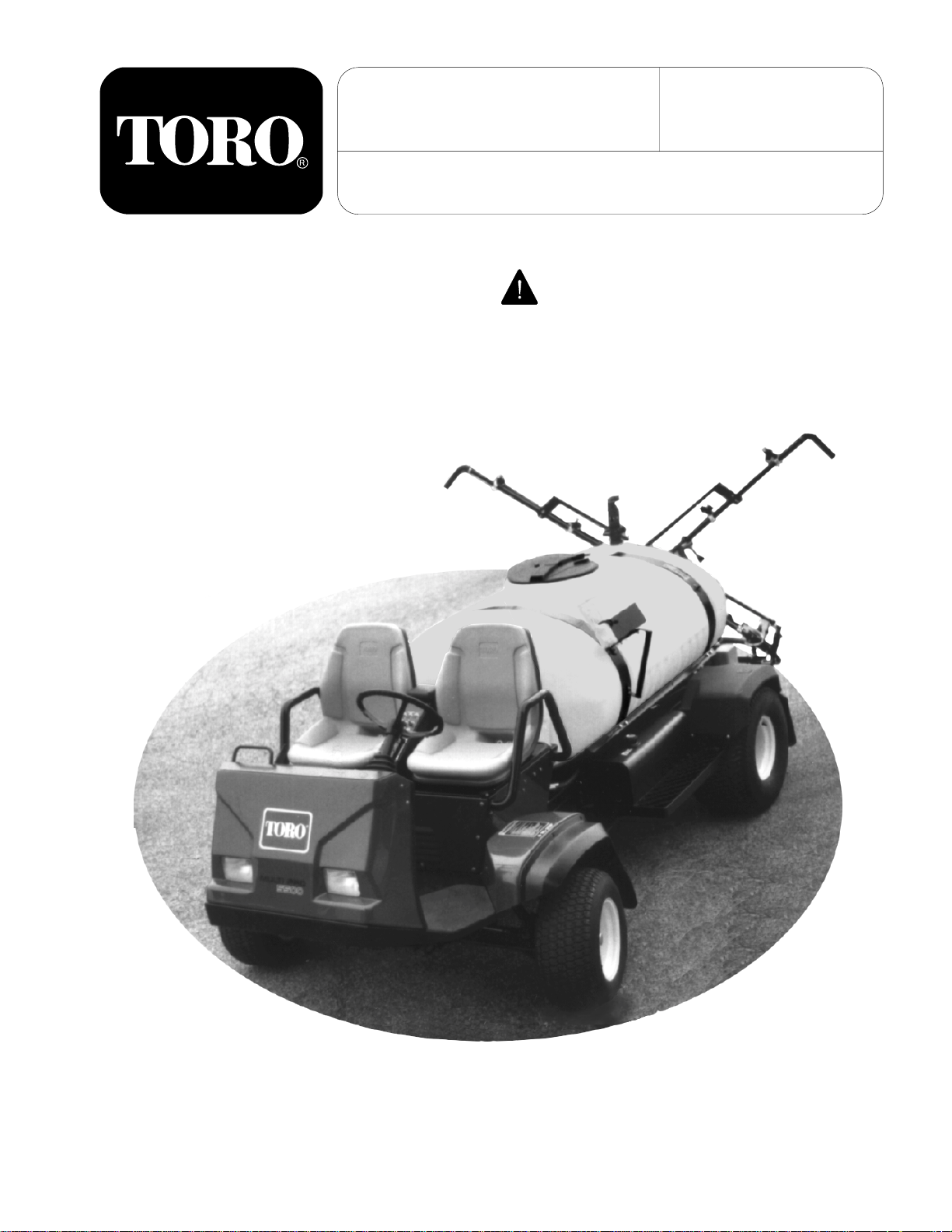
MULTI PRO® 5500
TURF SPRAYER
The safety alert symbol means CAUTION,
WARNING, or DANGER - personal safety
instruction. Failure to comply with the
instruction may result in personal injury.
©The TORO Company - 1998
All Rights Reserved
1
Page 2
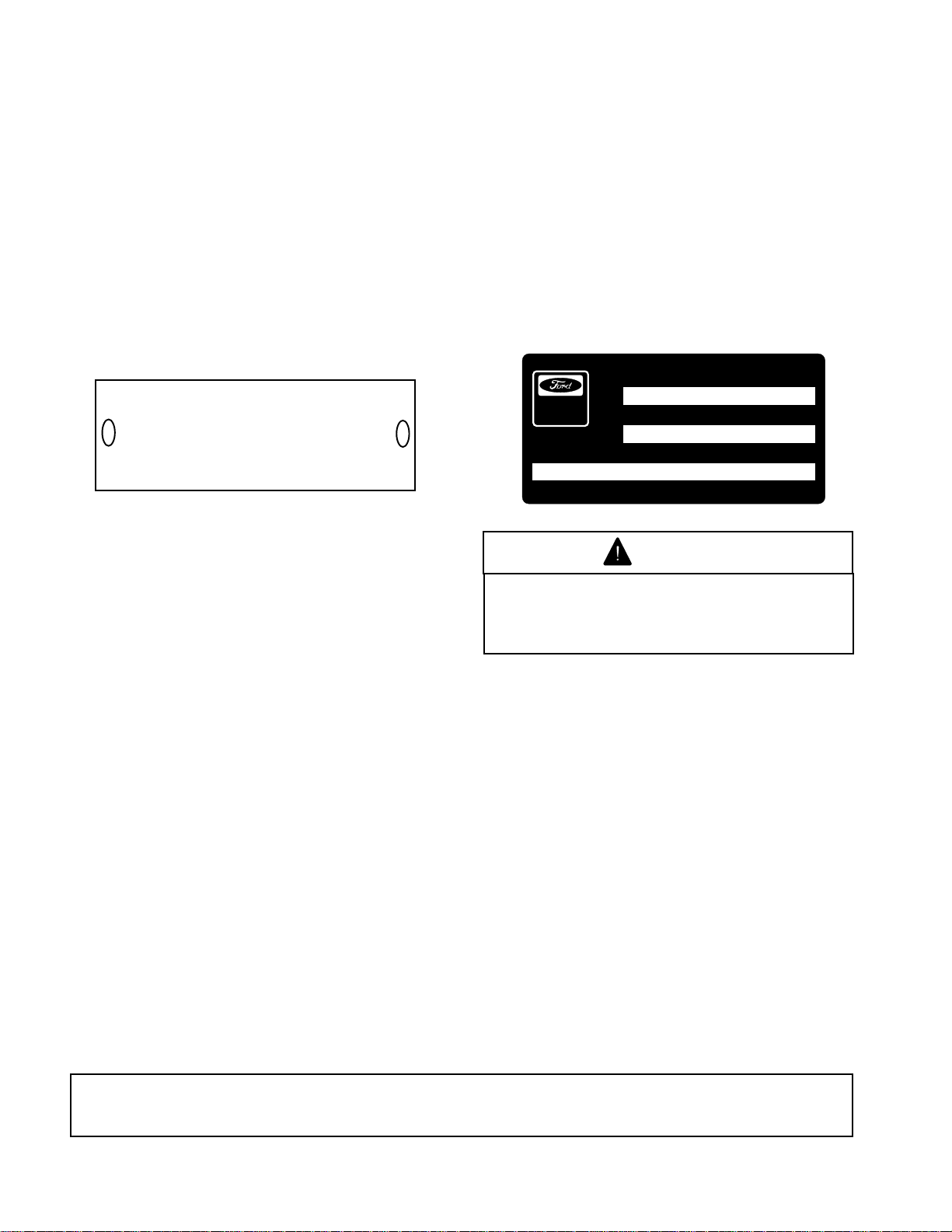
IDENTIFICATION AND ORDERING
VEHICLE:
The MULTI PRO
®
5500 has two identification
numbers: a model number and a serial number.
These numbers are stamped into a plate located
behind the left front fender of the vehicle. In any
correspondence concerning the unit, supply the
model number and serial numbers to ensure
correct information and replacement parts are
obtained. Record your Vehicle Identification
numbers on the illustration below for future
reference.
MOD.
SER.
THE TORO CO.
MINNEAPOLIS, MN. 55420
DATE PURCHASED: _______________________
This vehicle is not a motor vehicle as defined by
the National Traffic Motor Vehicle Safety Act. It is
not designed or manufactured for use on roads,
streets, or highways, and is not to be licensed
as a motor vehicle.
ENGINE:
An Identification Decal is affixed to the right side
of the engine. The decal contains the engine serial
number which identifies this unit from all others.
The model number and S.O.. or special options
determine the parts or components required on
this unit. When ordering parts or in any
communication involving the engine, it will be
necessary to supply the engine manufacturer with
these numbers, to ensure correct information and
replacement parts are obtained. Record the
engine identification numbers on the illustration
below for future reference.
SERIAL NUMBER
Power
Produ c ts
MODEL NUMBER
MODEL CODES.O./OPTIONS
WARNING
The engine exhaust from this product
contains chemicals known to the State
of California to cause cancer, birth
defects, or other reproductive harm.
FOREWORD
You have purchased a vehicle from the industry leader in maintenance excellence. Its future performance
and dependability are of prime importance. TORO is also concerned about future use of the vehicle and
of safety to the user. Therefore, this manual must be read by you and those involved with the MULTI
®
PRO
5500 to assure that safety, proper set-up, operation, and maintenance procedures are followed at
all times. The major sections of the manual are:
1. SAFETY INSTRUCTIONS
4. OPERATING INSTRUCTIONS
Safety, mechanical, and some general information in this manual are emphasized. DANGER, WARNING,
and CAUTION identify safety messages. Whenever the triangle safety symbol appears, it is followed by
a safety message that must be read and understood. For more details concerning safety, read the safety
instructions on pages 4 through 6. IMPORTANT identifies special mechanical information and NOTE
identifies general information worthy of special attention.
OPTIONAL SPARK ARRESTER
In some places a Spark Arrester muffler must be used because of local, state, or federal regulations. The
Spark Arrester available from your local TORO Distributor is approved by the United States Department
of Agriculture and the United States Forest Service.
When the machine is used or operated on any California forest, brush, or grass covered land,
a properly operating Spark Arrester must be obtained and installed to the Muffler. The operator
is violating state law, Section 442 Public Resources Code if a Spark Arrester is not used.
2. SET-UP INSTRUCTIONS
5. MAINTENANCE
3. BEFORE OPERATING
6. SPRAY SYSTEM SECTION
All information, illustrations and specifications in this manual are based on the latest product information available at the time of
publication. The right is reserved to make any changes at any time without notice.
2
Page 3

TABLE OF CONTENTS
SAFETY INSTRUCTIONS .................................................................................................... 4-6
SPECIFICATIONS ...................................................................................................................7
SAFETY AND INSTRUCTION DECALS ............................................................................... 8,9
SET-UP INSTRUCTIONS
BATTERY SERVICE ........................................................................................................ 10
SPRAY SYSTEM......................................................................................................... 11-14
FRESH WATER TANK ..................................................................................................... 14
BEFORE OPERATING ...................................................................................................... 15-19
VEHICLE CONTROLS ......................................................................................................20,21
OPERATING INSTRUCTIONS.......................................................................................... 22-26
MAINTENANCE ................................................................................................................26-44
DAILY MAINTENANCE SCHEDULE................................................................................ 27
MAINTENANCE SCHEDULE .......................................................................................... 28
JACKING VEHICLE ......................................................................................................... 29
LUBRICATION ................................................................................................................. 30
AIR CLEANER MAINTENANCE ...................................................................................... 31
ENGINE MAINTENANCE ........................................................................................... 32-33
COOLING SYSTEM MAINTENANCE.............................................................................. 34
BELT MAINTENANCE ..................................................................................................... 35
HYDRAULIC SYSTEM MAINTENANCE .......................................................................... 36
HYDRAULIC SYSTEM DIAGRAM ................................................................................... 37
HYDRAULIC SYSTEM ..................................................................................................... 38
BRAKE MAINTENANCE .................................................................................................. 39
THROTTLE LEVER TENSION ......................................................................................... 39
AXLE MAINTENANCE ..................................................................................................... 40
ELECTRICAL MAINTENANCE ........................................................................................ 41
VEHICLE ELECTRICAL DIAGRAM ................................................................................. 42
TRACTION DRIVE MAINTENANCE ........................................................................... 43-44
SPRAY SYSTEM
SPRAYING SYSTEM ..............................................................................................................45
CONTROLS AND OPERATION ............................................................................................. 46
BEFORE SPRAYING
NOZZLE SELECTION GPA/GAL/1000 FT2................................................................ 46,47
NOZZLE SELECTION LIT/HA ......................................................................................... 48
DEFINITIONS/CONVERSIONS ....................................................................................... 49
FRESH WATER WASH TANK ......................................................................................... 50
SYSTEM SET-UP............................................................................................................. 51
FILLING SOLUTION TANK.............................................................................................. 51
OPERATION
USING THE SPRAYER............................................................................................... 51,52
AFTER SPRAYING .......................................................................................................... 52
PREVENTATIVE MAINTENANCE ......................................................................................... 52
PUMP MAINTENANCE......................................................................................................... 53
MAINTENANCE
TROUBLESHOOTING SOLENOID VALVE...................................................................... 54
SOLENOID VALVE MAINTENANCE .......................................................................... 55,56
FLOW DIAGRAM .................................................................................................................. 57
SPRAY SYSTEM ELECTRICAL DIAGRAM .......................................................................... 58
STORAGE ............................................................................................................................. 59
PERFORMANCE VERIFICATION................................................................................... 60, 61
TORO PROMISE................................................................................................................... 64
3
Page 4

SAFETY INSTRUCTIONS
The MULTI PRO
®
5500 Turf Sprayer was
designed and tested to offer safe service when
operated and maintained properly. Although
hazard control and accident prevention partially
are dependent upon the design and
configuration of the vehicle, these factors are
also dependent upon the awareness, concern,
and proper training of the personnel involved
in the operation, maintenance, and storage of
the vehicle. Improper use or maintenance of
the vehicle can result in injury or death.
This is a specialized Turf Sprayer designed for
off road use. Its ride and handling will have a
different feel than what drivers experience with
passenger cars or trucks. So take time to
become familiar with your MULTI PRO
®
5500.
The attachments that adapt to the MULTI PRO
5500 are not covered in this manual. See the
specific Operator's Manual provided with the
attachment for additional safety instructions.
READ THESE MANUALS.
TO REDUCE THE POTENTIAL FOR INJURY OR
DEATH, COMPLY WITH THE FOLLOWING
SAFETY INSTRUCTIONS:
SUPERVISOR'S RESPONSIBILITIES
1. Make sure operators are thoroughly trained
and familiar with the Operator's Manual and all
labels on the vehicle.
2. Be sure to establish your own special
procedures and work rules for unusual operating
conditions (e.g. slopes too steep for vehicle
operation).
BEFORE OPERATING
3. Operate the vehicle only after reading and
understanding the contents of this manual. A
replacement manual is available by sending
complete model and serial number to: Hahn
Equipment Co., A subsidiary of The Toro
Company, 1625 N. Garvin, Evansville, Indiana
47711-4596.
5. This vehicle is designed to carry One
Operator, and One Passenger. Never carry more
than one passenger on the vehicle.
6. Never operate the vehicle when under the
influence of drugs or alcohol.
7. Become familiar with the controls and know
how to stop the engine quickly.
8. Keep all shields, safety devices, and decals
in place. If a shield, safety device, or decal is
malfunctioning, illegible, or damaged, repair or
replace it before operating the vehicle.
9. Always wear substantial shoes. Do not
operate vehicle while wearing sandals, tennis
®
shoes, or sneakers. Do not wear loose fitting
clothing or jewelry which could get caught in
moving parts and cause personal injury.
10. Wearing safety glasses, safety shoes, long
pants, and a helmet is advisable and required by
some local safety and insurance regulations.
11. Keep everyone, especially children and pets,
away from the areas of operation.
12. Before operating the vehicle, always check
all parts of the vehicle and any attachments. If
something is wrong, stop using the vehicle.
Make sure the problem is corrected before vehicle
or attachment is operated again.
13. Since gasoline is highly flammable, handle it
carefully.
A. Use an approved gasoline container.
B. Do not remove cap from fuel tank when
engine is hot or running.
C. Do not smoke while handling gasoline.
D. Fill fuel tank outdoors and to
approximately one inch below top of tank,
(bottom of filler neck). Do not overfill.
Read and understand the Engine Manufacturer's
Operator's Manual. Follow the safety alert
messages.
4. Never allow children to operate the vehicle
or adults to operate it without proper instructions.
Only trained and authorized persons should
operate this vehicle. Anyone who operates the
vehicle should have a motor vehicle license.
4
E. Wipe up any spilled gasoline.
14. The MULTI PRO
®
5500 is equipped with a
Neutral Lock-Out Switch. The purpose of this
switch is to insure that the vehicle will not start
unless the Traction Pedal is in the NEUTRAL
position. Should the vehicle start when the
Traction Pedal is not in the NEUTRAL position,
shut off the engine and refer to the Traction Drive
Maintenance instructions on pages 43 and 44.
Page 5

SAFETY INSTRUCTIONS
WHILE OPERATING
WARNING: Do not run engine in a confined
area without adequate ventilation. Exhaust
fumes are hazardous and could possibly be
deadly.
15. Operator and passenger should remain
seated whenever the vehicle is in motion. Operator
should keep both hands on steering wheel
whenever possible, and passenger should use
hand holds provided. Keep arms and legs within
the vehicle body at all times. Remember your
passenger may not be expecting you to brake or
turn and may not be ready.
16. Sit on seat when starting and operating the
vehicle.
17. When starting the engine:
A. Engage the Parking Brake.
B. Make sure Traction Pedal is in
NEUTRAL. Move the Throttle Lever to 1/4
to 1/3 throttle.
whenever possible. Reduce speed when
making sharp turns or when turning on
hillsides.
D. If engine stalls or loses power and
cannot make it to the top of a slope, do not
turn vehicle around. Always back slowly
straight down the slope.
E. Use extra caution when operating
vehicle on wet surfaces, at higher speeds
or with a full load. Stopping time will
increase with a full load.
F. Operate vehicle with extra caution
when handling off-center loads that cannot
be centered.
G. Avoid sudden starts and stops. Do not
go from reverse to forward or forward to
reverse without first coming to a complete
stop.
H. Do not attempt sharp turns or abrupt
maneuvers or other unsafe driving actions
that may cause a loss of vehicle control.
C. After engine is started, release parking
brake and keep foot off traction pedal. The
vehicle must not move. If movement is
evident, the neutral return mechanism is
adjusted incorrectly. Shut engine off and
refer to the Traction Drive Maintenance
section on pages 43 and 44.
18. Operator and passenger must be skilled and
trained in how to drive on hillsides. Failure to use
caution on slopes or hills may cause loss of control
and vehicle to tip or roll, possibly resulting in
personal injury or death.
19. Using the vehicle demands attention. Failure
to operate vehicle safely may result in an accident,
tip over of vehicle and serious injury or death.
Drive carefully. To prevent tipping or loss of
control:
A. Use extreme caution, reduce speed
and maintain a safe distance around sand
traps, ditches, creeks, ramps, and any
unfamiliar areas, or other hazards.
B. Watch for holes or other hidden
hazards.
I. Before backing up, be sure no one is
behind the vehicle. Back up slowly.
J. Watch out for traffic when near or
crossing roads. Always yield the right of
way to pedestrians and other vehicles. This
vehicle is not designed for use on streets
or highways. Always signal your turns and
stop early enough to let other people know
what you plan to do. Obey all traffic rules
and regulations.
K. Never operate vehicle in or near an
area where dust or fumes which are
explosive, are in the air. The electrical and
exhaust systems of the vehicle can produce
sparks capable of igniting explosive
materials.
L. Watch out for and avoid low overhangs
such as tree limbs, door jambs, overhead
walkways, etc. Make sure there is enough
room overhead to easily clear the vehicle
and your head.
M. If ever unsure about safe operation,
STOP WORK and ask your supervisor.
C. Always reduce speed before starting
up or down a hill. Do not start or stop
suddenly when traveling uphill or downhill.
Use caution when operating vehicle on a
steep slope. Normally travel straight up and
down slopes. Avoid turning on hillsides
5
Page 6

SAFETY AND INSTRUCTIONS
20. Do not touch Engine, Muffler, or Muffler Shield
while engine is running or soon after it has stopped
because these areas may be hot enough to cause
burns.
21. If the vehicle ever vibrates abnormally, stop
immediately, turn off engine, wait for all motion to
stop, and inspect for damage. Repair all damage
before commencing operation.
22. Before getting off the seat:
A. Remove foot from Traction Pedal,
stopping movement of the vehicle.
B. Set Parking Brake.
C. Shut engine off.
D. Remove Key from Ignition Switch.
E. Do not park on slopes unless wheels
are chocked or blocked.
MAINTENANCE
23. Before servicing, lubricating or making
adjustments to the vehicle, stop engine, set
Parking Brake and remove Key from Ignition
Switch to prevent accidental starting of the engine.
24. Make sure the vehicle is in safe operating
condition, keeping all nuts, bolts, and screws tight.
25. To reduce potential fire hazard, keep the
engine area free of excessive grease, grass,
leaves, and accumulation of dirt. Do not wash a
warm engine or electrical components.
26. Make sure all hydraulic line connectors are
tight, and all hydraulic hoses and lines are in good
condition before applying pressure to the system.
27. Keep body and hands away from pin hole
leaks in hydraulic lines that eject high pressure
hydraulic fluid. Use cardboard or paper to find
hydraulic leaks. Hydraulic fluid escaping under
pressure can penetrate skin and cause injury.
Fluid accidentally injected into the skin must be
surgically removed within a few hours by a doctor
familiar with this form of injury, or gangrene may
result.
28. Before disconnecting or performing any work
on the hydraulic system, all pressure in the system
must be relieved by stopping the engine.
29. If major repairs are ever needed or assistance
is required, contact an Authorized TORO
Distributor.
30. Disconnect battery before servicing the
vehicle. If battery voltage is required for
troubleshooting, temporarily connect the battery.
31. If the engine must be running to perform
maintenance, or an adjustment, keep hands, feet,
clothing, and any parts of the body away from the
engine and any moving parts. Keep everyone
away.
32. Do not over-speed engine by changing
Governor settings. Maximum engine speed is
3200 no-load rpm. To assure safety and accuracy,
have an Authorized TORO Distributor check
maximum engine speed with a tachometer.
33. Shut engine off before checking or adding oil
to the crankcase.
34. To assure optimum performance and
continued safety of the vehicle, always use
genuine TORO replacement parts and
accessories. Replacement parts and accessories
made by other manufacturers could be
dangerous. Altering this vehicle in any manner
may affect the vehicle's operation, performance,
durability, or its use may result in injury or death.
Such use could also void the product warranty of
the TORO Company.
35. This vehicle should not be modified without
The Toro Company's authorization. Direct any
inquiries to:
Hahn Equipment Co.
A subsidiary of The Toro Company
1625 N. Garvin Street
Evansville, IN 47711-4596
6
Page 7

SPECIFICATIONS
Vehicle: Four-wheel step through, out front
operator style, two person vehicle.
Engine: Ford, 4 cycle, 4 cylinder, overhead valve,
liquid cooled gas engine with centrifugal water
pump. Ford rates engine at 45 HP. Mechanically
governed to a maximum speed of 3200
79 cu. in. (1300 cc) displacement. Distributorless
electronic ignition. 3.5 quart (3.25 liter) oil
capacity; replacement oil filter. Forged connecting
rods, cast iron cylinder head and block.
Mechanical fuel pump.
Air Cleaner: Heavy duty, 2 stage, remote
mounted.
Battery: 12 volt with 420 cold cranking amps at
0° F.
Cooling System: Mid mounted radiator with oil
cooler mounted in front of radiator. Cooling
system capacity is 12 quarts (11.5 liters) of 50/50
mixture of ethylene glycol anti-freeze.
Fuel System: Capacity is approximately 10.6
gallon (40 liters) of lead-free gasoline.
+ 100 rpm.
Controls: Foot operated traction pedal, brake,
brake lock pedals, and remote boom on/off switch.
Hand operated throttle, speed control, choke
control, ignition switch, light switch, pressure
increase/decrease, master boom on/off, hydraulic
spray pump, agitator, and individual boom on/off
switches.
Gauges: Sprayer pressure gauge, engine oil
pressure warning light, temperature gauge,
voltmeter, and hour meter.
Lights: Twin halogen headlights.
Ground Speed: Working 2 - 6 mph
Transporting 0 - 11.5 mph
Reverse 0 - 4 mph
Sprayer Tank: 300 gallon capacity.
Spray Pump: Closed impeller hydraulic driven
centrifugal. Adjustable hydraulic drive. 120 gpm
(454 lpm), 100 psi (690 kpa) maximums.
Boom Assembly: Three section, 18.5 foot (5.6
meter) working width.
Traction System: Servo-controlled hydrostatic
system driving double planetary gear reduction
rear wheel drives. Foot pedal control of forward/
reverse ground speed.
Frame: Welded, high strength steel tubing.
Front Suspension: Straight axle with twin
independent leaf springs, dual shock absorbers.
Rear Suspension: Rigid frame.
Tires: Front: 23 x 10.5 x 12, 4-ply rating, turf tread.
Rear: 26.5 x 14 x 12, 4-ply rating, turf tread.
Brakes: Individual totally enclosed, multi-disc, wet
brakes and parking brakes on rear traction wheels.
Hydrostatic braking through traction drive.
Steering: Full hydraulic power with dedicated
power source.
Seats: Twin molded cushions and back rests, with
hip restraints.
Electrical Features: 12 volt, 420 cold cranking
amperes at 0° F, maintenance free battery. 51 amp
alternator with I/C regulator. Automotive type
electrical system. Traction interlock switch.
Nozzles: Drift reduction, quick disconnect with
diaphragm check valves.
General Specifications (approx.):
Base Weight: Base unit 1,750 lbs.
With standard spray sys.
and operator: dry 2,540 lbs.
full 5,040 lbs.
Maximum Gross Vehicle Weight: 6,040 lbs.
Measurements with spray system:
Overall Width: 72"
Overall Length: 136"
Height: 57-1/2"
Ground Clearance: 6-1/2"
Wheel Base: 78"
7
Page 8
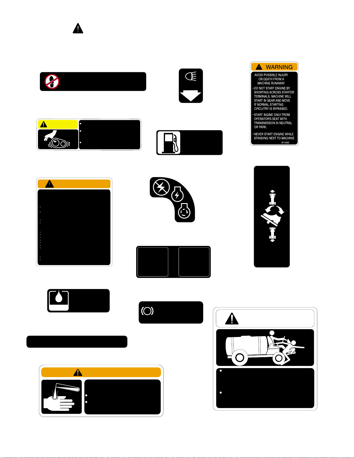
SAFETY AND INSTRUCTION DECALS
The following safety and instruction decals are installed on the vehicle. If any become damaged
or illegible, replace them. Decal part numbers are listed below and in the parts catalog. Order
replacements from your Authorized TORO Distributor.
94-7171
NO STEP
Part No. 36-3400: One Located on
right Front Fender, One on left Front
Fender.
CAUTION
Part No. 87-0450: Located on left side
WARNING
FAILURETO OBEY THE SAFETY WARNINGS MAY RESULT IN
INJURY TO YOU OR OTHERS.
THIS VEHICLE IS OF SUFFICIENT SIZE AND WEIGHT TO CAUSE
SERIOUS INJURY IN CASE OF UPSET OR COLLISION.
BEFORE OPERATING VEHICLE:
READ AND UNDERSTAND OPERATOR’S MANUAL LOCATED
BEHIND SEAT.
DO NOT EXCEED PAYLOAD CAPACITY OF VEHICLE AND/OR
TORO ACCESSORIES OR PERMIT PASSEGER ANY PLACE ON
VEHICLE EXCEPTSEAT.
USE HAND HOLDS WHERE APPLICABLE.
PLACE HEAVYLOADS FORWARD OF REAR AXLE.UNBALANCED
OR TOP HEAVYLOADS CAN CAUSE UPSET.
BEFORE OPERATING VEHICLE:
REMAIN SEATED AND USE BOTHHANDS FOR STEERING.
KEEP ARMS AND LEGS WITHIN VEHICLE BODY.
AVOID SUDDEN STARTS AND STOPS
SUDDEN SHARP TURNS CAN CAUSE UPSET.
REGULATE SPEED TO MEET ROAD AND WEATHER CONDITIONS.
DO NOT OPERATE IN OR NEAR AN EXPLOSIVE ENVIRONMENT.
IF A MALFUNCTION OCCURS, CEASE OPERATION. DO NOT
OPERATE VEHICLE UNTIL CONDITION IS CORRECTED.
BEFORE LEAVINGVEHICLE:
TURN IGNITION TO "OFF" POSITION, REMOVEKEY.
APPLY PARKING BRAKE; PARKING BRAKE IS NOT
AUTOMATICALLY APPLIED.
Part No. 87-0580: Located on Left
Front Fender.
Part No. 85-4730: Located on top of
Hydraulic Tank.
BOOM SECTION
BOOM 1 BOOM 2 BOOM 3
Part No. 94-7173: Located on Dash
Panel, above Indicator Lights.
TO AVOID PERSONAL INJURY KEEP
ALL SHIELDS IN PLACE.
DISENGAGE AND SHUT OFF
ENGINE BEFORE SERVICING OR
UNCLOGGING MACHINE.
KEEP HANDS, FEET AND CLOTHING
AWAY FROM POWER-DRIVEN PARTS.
of Center Console.
87-0580
HYDRAULIC
OIL ONLY
USE MOBIL 424
85-4730
94-7173
36-3400
87-0450
Part No. 71-3730: Located on
Part No. 87-0500: Located on Dash
Panel, above Key Switch.
MASTER
BOOM
ON/OFF
Part No. 94-7132: Located on Floor
Board, left of Brake Lock Pedal.
PARKING BRAKE
1. DEPRESS BRAKE PEDAL
P
2. DEPRESS PARKING
BRAKE LOCK
Part No. 94-7172: Located
on left side of Dash Panel,
under Steering Wheel.
LIGHTS
Part No. 94-7171:
Located on Dash Panel,
right of Light Switch.
GAS
ONLY
top of Gasoline Tank.
PARKING
BRAKE
94-7132
LOCK
94-7172
71-3730
Part No. 87-0430: Located behind Left
Front Fender.
TRACTION
PEDAL
FORWARD
92-0479
REVERSE
VEHICLE SPEED
INCREASES
WITH MORE PEDAL
PRESSURE
Part No. 92-0479: Located on
Floorboard, right of Traction Pedal.
WARNING
LEAVING SEAT WHILE VEHICLE IS
IN MOTION COULD RESULT IN SERIOUS
INJURY OR DEATH.
ALWAYS ALLOW VEHICLE TO COME
TO A COMPLETE STOP BEFORE
EXITING OR BOARDING VEHICLE.
Part No. 95-2136: Located on
the right end of the Dash.
95-2136
93-0688
WARNING
CHEMICALS CAN BE HAZARDOUS
TO REDUCE THE RISK OF ENVIRONMENTAL
DAMAGE AND PERSONAL INJURY
SELECT THE CORRECT CHEMICAL FOR THE
APPLICATION.
HANDLE AND APPLY CHEMICALS AS
INSTRUCTED BY THE CHEMICL
MANUFACTURER’S LABELS. ALWAYS
WEAR PROTECTIVE CLOTHING AND MASK.
Part No. 93-0688: Located on
Spray Tank Lid.
8
Page 9

SAFETY AND INSTRUCTION DECALS
The following safety and instruction decals are installed on the vehicle. If any become damaged
or illegible, replace them. Decal part numbers are listed below and in the parts catalog. Order
replacements from your Authorized TORO Distributor.
Part No. 62-5550: Located on Front of
Front Console.
READ YOUR OPERATOR’S MANUAL FOR OPERATING AND
SAFETY INSTRUCTIONS. TO GET A REPLACEMENT MANUAL,
SEND MODEL AND SERIAL NUMBERS TO : THE TORO CO., 8111
LYNDALE AVE. S., MPLS., MN 55420
Part No. 65-3090: Located on left side
of Dash Panel.
SPEED CONTROL
WARNING
IMPROPER USE OF
SPEED CONTROL
COULD RESULT IN
PERSONAL INJURY.
SEE OPERATOR’S
MANUAL PRIOR TO
OPERATION.
ON
OFF
94-7175
VEHICLE LOAD AND TURF
CONDITIONS AFFECT BRAKE
PERFORMANCE. FAILURE TO
OPERATE VEHICLE PROPERLY
COULD RESULT IN PERSONAL
INJURY.
AVOID HIGH SPEEDS OR ABRUPT
STOPS ON SLOPES AND WET
TURF.
SEE OPERATOR’S MANUAL
FOR ADDITIONAL INFORMATION.
65-3090
WARNING
94-7176
ON
L
T
H
OFF
FOAM MARKER
R
O
T
T
L
E
ON
OFF
MASTER
BOOM
ON
OFF
BOOM 1 BOOM 2 BOOM 3
ON
DOWN DOWN
L
UP UP
BOOM LIFT
LOWER
RAISE
PRESSURE
(DUMP BED)
ON
OFF
PUMP
ON
OFF
ON
ON
R
OFF
R
AUTO
OFF
(SET)
MAN
SONIC
BOOM
ON
OFF
AGITATOR
ON
OFF
ON
SET
Part No. 94-7175: Located on Dash
Panel, right of Steering Wheel.
CAUTION
Part No. 42958: Located on
left radiator brace.
CAUTION
Part No. 87-0570: Located on Rear
Tank Band.
TO AVOID ELECTRIC SHOCK
AND PERSONAL INJURY TO
INSPECT AREA OVERHEAD FOR
WIRES BFORE RAISING BOOMS.
KEEP BYSTANDERS AWAY WHILE
RAISING AND LOWERING BOOMS.
Part No. 94-7176: Located
on Dash panel, under grab bar.
BYSTANDERS
87-0570
OFF
AGITATOR
CHEM 1
OFF
RINSE
PUMP
InJector Pro™
OFF
AGITATOR
CHEM 2
94-7134
Part No. 94-7134: Located on the Center
Console.
Part No. 94-7133: Located on
Front of Front Console.
9
Page 10
SET-UP INSTRUCTIONS
BATTERY SERVICE:
CAUTION
Electrolyte gases are explosive and can
cause serious injury to eyes, lungs, and
skin. Nausea may result if the gases are
inhaled.
Wear safety goggles and rubber gloves
when working with electrolyte or battery.
Charge the Battery in a well ventilated
place so gases produced while charging
can dissipate.
Unplug charger from electrical outlet
before connecting to or disconnecting
charger leads from battery posts.
Since the gases are explosive, keep open
flames and electrical spark away from the
battery; DO NOT SMOKE!
The Battery has been filled with electrolyte and
charged at the factory. However, prior to actual
operation, it may be necessary to bring the Battery
to a full charge as follows:
1. First disconnect the black negative (-) cable,
then disconnect the red positive (+) cable.
2. Connect a 3 to 4 amp battery charger to the
Battery Posts. Charge the Battery at a rate of 3 to
4 amperes for 4 to 8 hours.
3. When Battery is charged, disconnect the
charger from electrical outlet and battery posts.
IMPORTANT! If optional electric powered
equipment is to be installed on the MULTI PRO
5500, DO NOT connect the battery cables until
all wiring harness connections for the optional
equipment have been completed. If
accidentally grounded, the lead to the battery
terminal will burn the accessory's wiring
harness. After the accessory's wiring harness
has been connected, proceed as follows:
4. Connect the red positive (+) cable to the
positive (+) post on the battery first, then connect
the black negative (-) cable to the negative (-)
post on the battery. Secure with cap screws and
nuts. Slide the rubber boot over the positive
terminal to prevent short-out from occurring.
WARNING
Connecting cables to the wrong post
could cause the battery to explode,
resulting in personal injury and damage
to the electrical system.
Make sure Battery Cables do not interfere
or rub on any moving or hot parts.
®
10
Page 11
SET-UP INSTRUCTIONS
CAUTION
Chemicals are hazardous and can cause
personal injury!
Securely tighten all sprayer hose clamp
connections during initial set-up to
prevent leaks and hose blow-offs while
spraying system is in operation.
SPRAY SYSTEM:
NOTE: In the following instructions, "sealer"
refers to the Teflon Thread Tape.
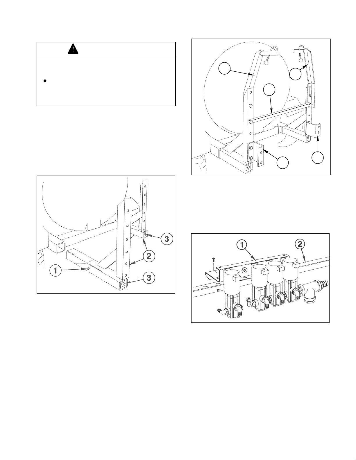
1. Apply a heavy coating of grease to the tubes
of the two Boom Mount Assemblies and insert
them into the Vehicle Frame until Stop Pin bottoms
out against Vehicle Frame. (See FIG. 1.)
1
1
2
3
3
1140
Figure 2
1. Boom Hold-In Ass'y. 3. Boom Mounting
2. Angle Crossmember Bracket
1139-1
Figure 1
1. Stop Pin 3. 1/2" x 18" screws
2. Boom Mount Ass'y.
2. Using a torque wrench, tighten the 1/2" x 18"
screws that join the Wedges to the Boom Mounts.
Tighten to 50 ft. lbs.
NOTE: If installing the "Enclosed Boom" option
in place of the Standard Boom, DO NOT install
the (2) Boom Hold-In Assemblies in Step 3 or
the (2) Boom Mounting Brackets in Step 4.
.
3. Install the two (2) Boom Hold-In Assemblies
and the Angle Crossmember to the top of the
Boom Mount uprights as shown in FIG. 2, using
four (4) 1/2" x 1-1/4" cap screws, flat washers and
lock nuts.
5. Attach the Solenoid Assembly to the Angle
Crossmember with four (4) 5/16" hex head cap
screws and hex nuts. (See FIG. 3.)
1015
Figure 3
1. Solenoid Ass'y 2. Angle Crossmember
NOTE: If installing the "Enclosed Boom" option
in place of the Standard Boom, skip steps 6-19.
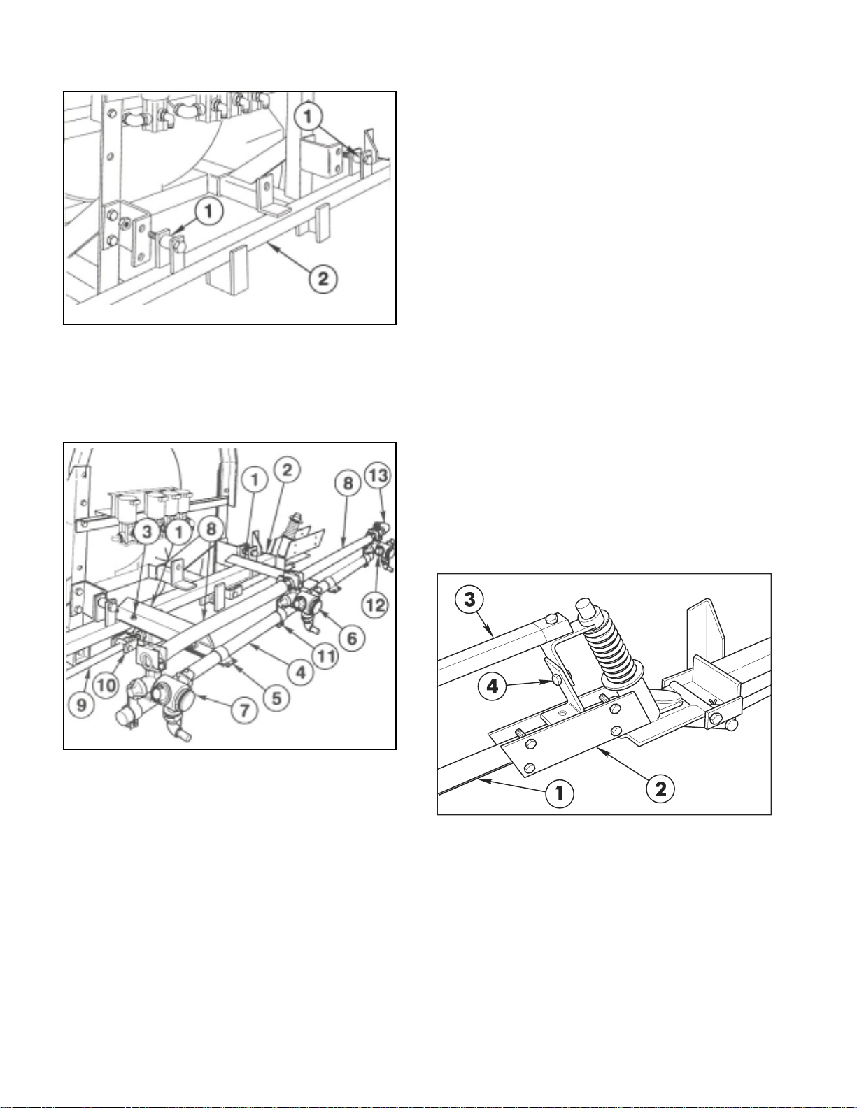
6. Position a Spacer Tube between the lugs on
each side of the Main Frame tube. Insert a 1/2" x
2-1/2" cap screw through the lugs and spacers.
Secure the Main Frame to the Boom Mounting
Brackets with lock nuts. (See FIG. 4.)
4. Attach the two "U"-shaped Boom Mounting
Brackets to the bottom of the Boom Mount
uprights with four (4) 1/2" x 1-1/4" cap screws, and
lock nuts. (See FIG. 2.)
11
Page 12
SET-UP INSTRUCTIONS
1141
Figure 4
1. Spacer Tube 2. Main Frame
10. Loosely attach a Single Barb Turret Body with
the Turret Body Clamp to LH end of the Center
Boom Pipe. Loosely attach a threaded Turret Body
with the Turret Body Clamp to RH end of the Center
Boom Pipe.
11. Place two Hose Clamps on two 3/4" x 19"
Jumper Hoses and connect the two "end" Turret
Bodies to the Double Barb Turret Body. Space
nozzles 20" apart and tighten fasteners securely.
Apply thread sealer and install the 90° 3/4" Hose
Barb on the Threaded Turret Body. (See FIG. 5.)
12. Attach the two Strut Assemblies to the two
adjustable clevis' found on each side of the Main
Frame tube with two (2) 1/2" x 2" clevis pins and
two (2) 1/8" x 1" cotter pins. (See FIG. 5)
7. Position the two (2) Center Boom angles on
the Main Frame and secure them to the Main
Frame tube with two (2) square U-bolts, four (4)
flat washers and hex nuts. (See FIG. 5.)
1016
Figure 5
1. Center Boom Angle 8. Jumper Hose
2. Main Frame 9. Strut Assembly
3. U-bolt 10. Adjustable Clevis
4. Center Boom Pipe 11. Turret Body Clamp
5. Boom Clamp 12. Threaded Barb Turret
6. Double Barb Turret 13. 90° Hose Barb
7. Single Barb Turret
8. Center and attach the Center Boom Pipe to
the two Center Boom Angles with two (2) clamps,
(2) 3/8" x 1" cap screws, flat washers and lock nuts.
Once mounted the Center Boom Pipe should be
approx. 20" from ground.
9. Loosely attach the Double Barb Turret Body
with the Turret Body Clamp in the approximate
center of the Center Boom Pipe. For the most
uniform spray coverage, position all Nozzles level
as shown in FIG. 5.
NOTE: If the optional "Foam Marker Kit" is to
be installed, refer to the instructions furnished
with that kit before proceeding to step 13.
IMPORTANT! DO NOT over-tighten the nuts in
steps 13 and 15. The clamping action could
crush the Boom Pipe.
13. Insert the plugged end of an Extension Boom
Pipe into the Pivot Assembly and secure with four
(4) 1/4" x 1-1/4" cap screws and lock nuts. (See
FIG. 6) Repeat on the opposite side to assemble
the other Extension Boom.
Figure 6
1. Extension Boom Pipe 3. Boom Support
2. Pivot Assembly Assembly
4. Height Adjustment
14. Attach the LH Boom Support Assembly to the
Pivot Assembly, using a 5/16" x 1-1/2" cap screw
and lock nut. (See FIG. 6 & 7.)
15. Secure the two plates of the Boom Support
Assembly to the Extension Boom Pipe, using two
(2) 1/4" U-bolts, four (4) lock nuts and flat washers.
(See FIG. 7.)
12
Page 13

SET-UP INSTRUCTIONS
2
1
TO CONTROL
VALVE
WHITE
WHITE
BROWN
BLUE
BLACK
1017
Figure 7
1. Boom Support Ass'y 5. Single Barb Turret
2. Extension Boom Pipe 6. Jumper Hose 3/4 x 19"
3. U-bolt 7. Boom Cap
4. Double Barb Turret 8. Jumper Hose 3/4 x 21"
16. Assemble the RH Boom Support Assembly to
the other Extension Boom Pipe.
17. Adjust the Booms to a level position by
adjusting the jam nuts on the adjustable clevis
assemblies (See FIG. 5) to the desired position,
then tighten the end nuts against the Main Frame
plate.
18. Attach three Double Barb Turret Bodies and
one Single Barb Turret Body with Clamp
Assemblies on each Extension Boom Pipe as
shown in FIG. 7.
19. Level Nozzles and space 20" apart. Connect
the Turret Body Assemblies with 3/4" x 19" Jumper
Hoses and a 3/4" x 21" Jumper Hose. Secure with
hose clamps. (See FIG. 7.)
20. Apply thread sealer and install a 90° hose barb
into the top of the Tee at the pump for Boom supply.
Attach one end of the 1-1/4" x 52" Supply Hose to
the 90° hose barb, and secure with a hose clamp.
(See FIG. 10)
21. Attach the other end of the Supply Hose to the
hose barb in Tee at the Solenoid Assembly. Secure
with two hose clamps, one clamp at 1/4" and the
other clamp at 1-1/4" from the hose barb hex. (See
FIG. 8 & 9)
22. Secure the Supply Hose to the Solenoid
Assembly using a large "R" clamp. (See FIG. 8)
Figure 8
1. Supply Hose 4. Small "R" Clamp
2. Large "R" Clamp 5. Solenoid Valve Shield
3. Wiring Harness 6. Hyd. Control Valve Plug
24. Connect the plug on the wiring harness to the
mating plug from the Hydraulic Control Valve. Then
make connections to the four solenoid valves as
shown in FIG. 8 & 9.
Figure 9
1. 90° Hose Barb 3. Supply Hose
2. Gauge Tube
25. Install Gauge Tube into the 90° street elbow at
through port of Solenoid Assembly and secure
with Compression Adapter. (See FIG. 9)
26. Install Solenoid Valve Shield to top of Solenoid
Mounting Bracket using two (2) 1/4 x 3/8" flange
screws. (See FIG. 8)
23. Route wiring harness across rear of vehicle and
secure to Solenoid Assembly with a small
"R" clamp. (See FIG. 8)
13
Page 14
SET-UP INSTRUCTIONS
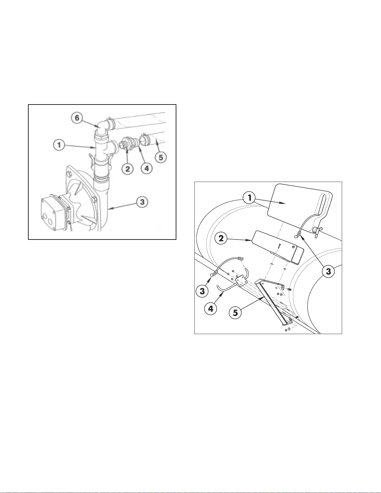
27. Apply thread sealer and install Reducing
Bushing into side of Tee on top of Pump. Install 1"
MPT x 3/4" hose barb into Reducing Bushing, and
attach one end of the Agitator Solenoid Feed
Hose. (See FIG. 10) Secure with a hose clamp.
Attach other end of hose to the 90° hose barb at
the side of the Agitator Solenoid. (See FIG. 9)
Secure with a hose clamp.
FRESH WATER TANK (Fig. 11)
1. Mount Brace assembly to the two (2) 5/16"
carriage bolts in the right side front Tank Band
using two (2) 5/16" flat washers and hex nuts.
Tighten securely.
NOTE: Left hold-in assembly and hardware will
not be used.
2. Mount Wash Tank Bracket (open end forward)
to right-hand Hold-In Brace assembly using two
(2) 5/16" x 1" hex hd. cap screws, flat washers,
and hex nuts. Place Clean Water Wash Tank into
Wash Tank Bracket and secure with Rubber HoldDown, as shown in FIG. 11.
NOTE: Tighten all fasteners and hose clamps
securely before using the spray system.
1142
Figure 10
1. Tee 4. Hose Barb
2. Reducing Bushing 5. Agitator Feed Hose
3. Pump 6. 90° Hose Barb
NOTE: If installing the "Enclosed Boom" option
in place of the Standard Boom, skip Steps 2830 and refer to the instructions furnished with
that kit before continuing with Step 31.
28. Attach the Boom Feeder Hoses to the barbs
in the Solenoids with hose clamps.
29. Place a hose clamp on the center Boom
Feeder Hose and attach it to the 90° Hose Barb at
the RH end of Center Boom Pipe.
30. Place a hose clamp on the right and left Boom
Feeder Hoses and attach them to the double barb
nozzles on the right and left Boom Pipes.
31. Install the "Anti-Siphon Kit". Instructions and
parts are included with your MULTI PRO
®
5500
Turf Sprayer.
Figure 11
1. Clean Water Wash Tank 4. Boom Hold-In Ass'y
2. Wash Tank Bracket 5. Hold-In Brace Ass'y
3. Rubber Hold-Down
NOTE: If installing the optional "Foam Marker
Kit", refer to the instructions furnished with
that kit for remaining set-up procedures.
14
Page 15
BEFORE OPERATING
CAUTION
Servicing the vehicle while the engine is
running or vehicle is not properly secured
could result in personal injury or death.
Before servicing or making adjustments
to the vehicle, stop engine, set parking
brake, and remove key from the switch.
IMPORTANT! Check level of oil BEFORE EACH
USE, while engine is cool so the oil has had
some time to drain into the sump.
SINGLE VISCOSITY OILS
Outside Temperature
- 10°F to +60°F SAE 10W
+10°F to +90°F SAE 20W-20
Above +32°F SAE 30
Above +50°F SAE 40
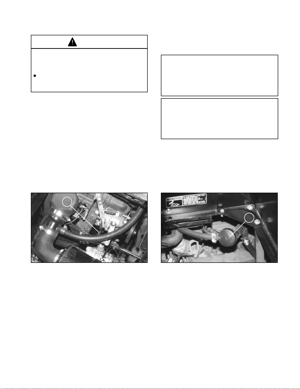
CHECK ENGINE OIL (Fig. 12 a, b)
The engine is shipped with approximately 3.5
quarts (3.25 liter) of oil in the crankcase; however,
level of oil must be checked before and after
the engine is first started.
1. Position vehicle on a level surface. Tilt right
seat forward to gain access to the engine
compartment.
2. Remove dipstick from oil tube, wipe clean,
and reinstall into the tube. Pull it out again and
check oil level on dipstick. Oil level must be
maintained between the minimum and maximum
marks on the dipstick.
MULTI-VISCOSITY OILS
Outside Temperature
Below +60°F SAE 5W-30
- 10°F to +90°F SAE 10W-20
Above -10°F SAE 10W-40 or 10W50
Above +50°F SAE 20W-40 or 20W50
Change oil and filter after the first 50 hours of
operation. Thereafter, change oil and filter after
every 100 hours of operation. Change oil more
frequently when engine is operated in extremely
dusty or dirty conditions. See page 32.
Figure 12 a
1. Oil Dipstick
3. If oil level is low, tilt drivers side seat forward,
remove oil fill cap, and add Ford or Motorcraft oil
or equivalent that meets Ford Specification ESEM2C153-E and API categories SG, SG/CC or
SG/CD until level is between the "MIN" and "MAX"
marks on the dipstick. DO NOT OVERFILL. See
viscosity chart for recommended weight to use.
4. Install the dipstick firmly in place.
5. Install oil fill cap.
6. Close access door and secure handle.
7. Lower seat to original seating position.
Figure 12 b
1. Filler Cap
15
Page 16

BEFORE OPERATING
CAUTION
If engine has been running, pressurized
hot coolant can escape and cause burns
if cap is removed.
Before removing cap, allow engine to
cool for at least 15 minutes or until the
cap is not hot to the touch.
CHECK COOLING SYSTEM (Fig. 13)
Capacity of system is 12 quarts (11.5 liters). The
cooling system is filled with a 50/50 solution of
water and permanent ethylene glycol anti-freeze.
Check level of coolant at beginning of each day
before starting the engine.
1. Park machine on level surface and fold seats
forward.
1143
Figure 13
1. Coolant level 2. Radiator cap.
(3/4 to 1-1/2 inches
below cap seal.)
2. When engine is cool remove radiator cap
and check coolant level. Coolant level should be
approximately 3/4 to 1-1/2 inches below the filler
neck seat when the coolant is cold.
3. If coolant is low, add a 50/50 mixture of water
and antifreeze. DO NOT USE WATER ONLY OR
ALCOHOL/METHANOL BASE COOLANTS.
4. Replace radiator cap securely.
16
Page 17
BEFORE OPERATING
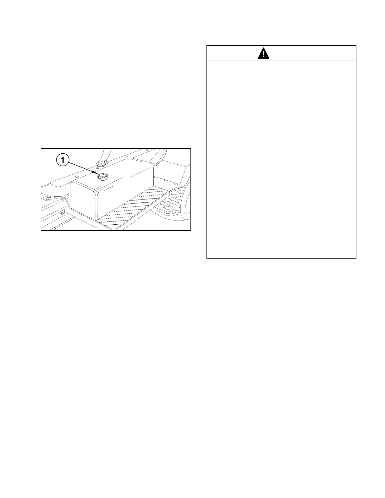
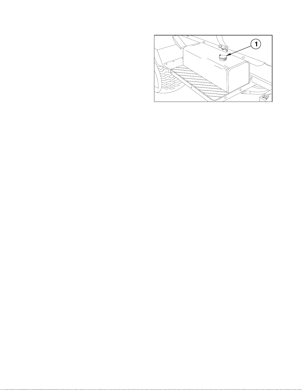
FILL FUEL TANK (Fig. 14)
Fuel tank capacity is 10.6 gallons (40 liters).
THE TORO COMPANY STRONGLY
RECOMMENDS THE USE OF FRESH, CLEAN
UNLEADED REGULAR GRADE GASOLINE IN
TORO GASOLINE POWERED PRODUCTS.
UNLEADED GASOLINE BURNS CLEANER,
EXTENDS ENGINE LIFE, AND PROMOTES
GOOD STARTING BY REDUCING THE BUILDUP
OF COMBUSTION CHAMBER DEPOSITS.
MINIMUM OCTANE RATING OF 87.
1144
Figure 14
1. Fuel tank cap.
DANGER
Because gasoline is flammable, caution
must be used when storing or handling
it. Do not fill fuel tank while engine is
running, hot, or when vehicle is in an
enclosed area. Vapors may build up and
be ignited by a spark or flame source
many feet away. DO NOT SMOKE while
filling the fuel tank to prevent the
possibility of an explosion. Always fill fuel
tank outside and wipe up any spilled
gasoline before starting the engine. Use
a funnel or spout to prevent spilling
gasoline, and fill tank no higher than one
inch below top of tank, (bottom of filler
neck). DO NOT OVER FILL. Store
gasoline in a clean safety approved
container and keep the cap on the
container. Keep gasoline in a cool, well
ventilated place; never in an enclosed
area such as a hot storage shed. To
assure volatility, do not buy more than a
30 day supply of gasoline. Gasoline is a
fuel for internal combustion engines;
therefore do not use it for any other
purpose. Since many children like the
smell of gas, keep it out of their reach
because the fumes are explosive and
dangerous to inhale.
IMPORTANT! NEVER USE METHANOL,
GASOLINE CONTAINING METHANOL,
GASOLINE CONTAINING MORE THAN 10%
ETHANOL, GASOLINE ADDITIVES, OR WHITE
GAS. ENGINE FUEL SYSTEM DAMAGE COULD
RESULT.
1. Clean area around fuel tank cap.
2. Remove fuel tank cap.
3. Fill tank to about one inch below top of tank
(bottom of filler neck). DO NOT OVERFILL. Then
install cap.
4. Wipe up any fuel that may have spilled to
prevent a fire hazard.
FUEL GAUGE: The Fuel Tank Cap shows amount
of fuel in tank.
17
Page 18
BEFORE OPERATING
1145
CHECK HYDRAULIC FLUID (Fig. 15)
IMPORTANT! ALWAYS USE EXTREME
CAUTION WHEN FILLING THE RESERVOIR OR
CHECKING THE LEVEL OF THE HYDRAULIC
FLUID. KEEP THE SYSTEM FREE OF
CONTAMINANTS.
1. Position vehicle on a level surface, set parking
brake, and stop the engine
2. Clean area around filler neck and cap of
hydraulic tank. Remove cap from filler neck.
Figure 15
3. If level is low, add appropriate fluid to raise
level to two inches from top of the tank (bottom of
strainer) DO NOT OVERFILL.
4. Install cap onto filler neck.
5. Start engine.
6. Turn the steering wheel completely to the left,
then completely to the right.
7. Turn off the engine and recheck level of
hydraulic fluid. Replenish as required.
1. Hydraulic fluid tank cap.
The vehicle's reservoir is filled at the factory with
approximately 12 gallons (45.42 liters) of Mobil
424 hydraulic fluid. Check level of hydraulic fluid
before engine is first started and daily
thereafter.
18
Page 19
BEFORE OPERATING
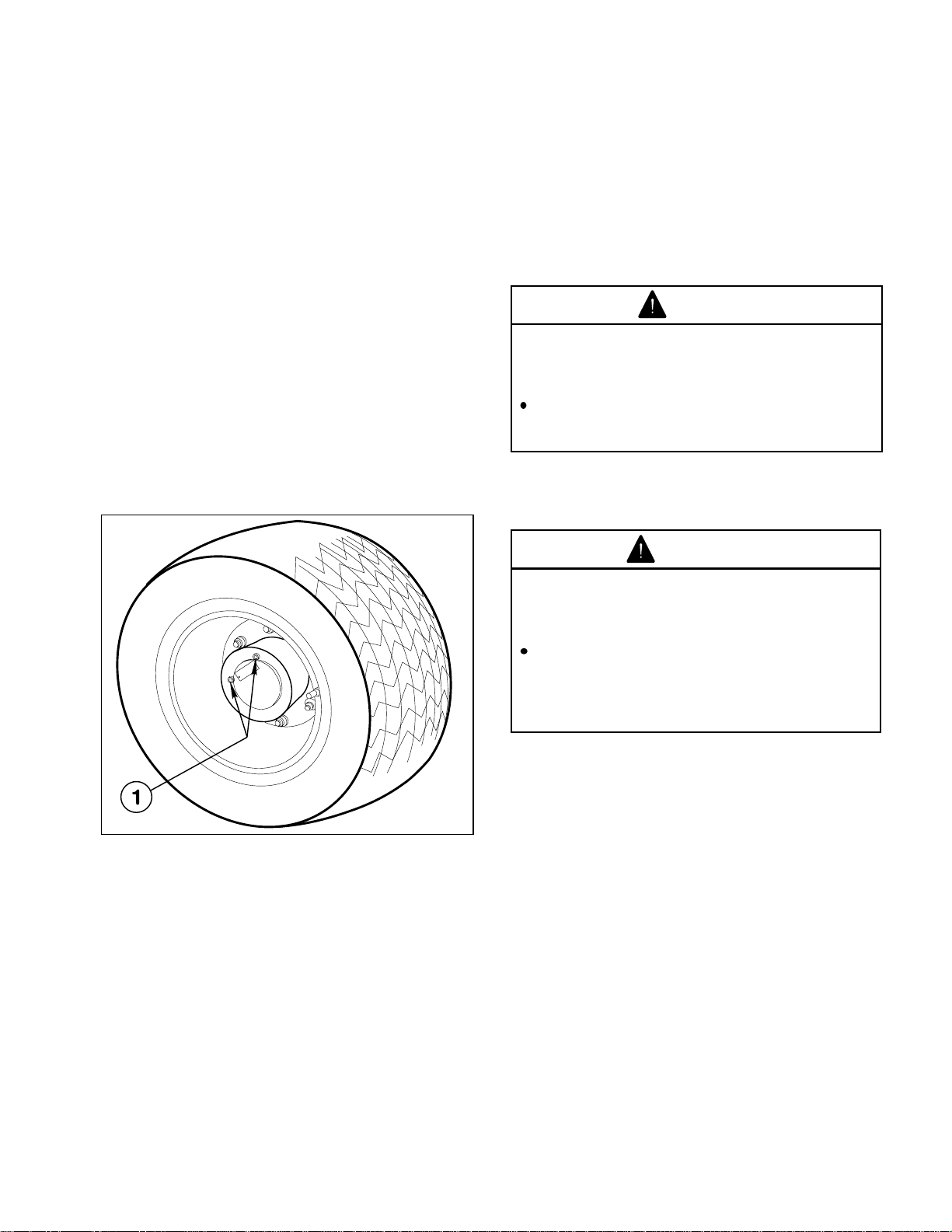
CHECK PLANETARY GEAR OIL
(Fig. 16)
Check oil if external leakage is noted. Use high
quality SAE 85W-140 wt. gear lube replacement.
Capacity of system is 16 oz.
1. With machine on level surface, position wheel
so check/drain plugs are at the 9 and 12 o'clock
position.
2. Remove the 9 o'clock positioned plug. Oil
should be to bottom of the hole.
3. If necessary add gear oil to the 12 o'clock hole
until oil begins to flow from the 9 o'clock hole.
4. Wipe surface clean and reinstall plugs.
5. Repeat steps 1 through 4 on opposite gear
assembly.
CHECK EMERGENCY/PARK BRAKE
Adjust the Emergency/Park Brake when there is
more than 1 inch of "free travel" of the Brake Pedal,
or if the Brake does not work effectively. "Free
travel" is the distance the Brake Pedal moves
before braking resistance is felt. To reduce "free
travel" of brake pedal see the MAINTENANCE
section on "ADJUSTING BRAKES".
DANGER
Operating the vehicle with worn or poorly
adjusted brakes can result in serious
injury or death.
If Brake Pedal travels to within 1 inch of
the Vehicle floor board, the brakes must
be adjusted or repaired.
CHECK TORQUE OF WHEEL NUTS
WARNING
1146
Figure 16
1. Check/Drain Plugs
Failure to maintain proper torque could
result in failure or loss of wheel and may
result in personal injury.
Torque front wheel nuts to 55-65 ft-lb (7588N-m) and rear wheel nuts or bolts to
85-100 ft-lb (116-136 N-m) after 1-4 hours
of operation and every 200 hours
thereafter.
IMPORTANT! After the "initial run-in"
(approximately one to two hours) check all the
MULTI PRO
tightness.
®
5500 wheel fasteners for
CHECK TIRE PRESSURE
Check tire pressure every 8 hours or daily to assure
proper levels. Maximum air pressure in both front
and rear tires is 18 p.s.i.
The air pressure needed is determined by the
payload carried. Once the desired pressure has
been ascertained, it is to be used and maintained
to insure the accuracy of the spraying system.
INSPECT TIRES
Check tire condition for wear or damage.
Operating accidents, such as hitting curbs, can
damage a tire or rim and also disrupt wheel
alignment, so inspect tire condition after any
accident.
19
Page 20
VEHICLE CONTROLS
Familiarize yourself with the controls and
recommended operating procedures before
operating the MULTI PRO
TRACTION PEDAL: (Fig. 17) Controls forward
and reverse operation. Depress top of pedal to
move forward and bottom of pedal to move
backward. Ground speed depends on how far
pedal is depressed. For maximum ground speed,
fully depress pedal while throttle is in FAST.
To stop, reduce foot pressure on traction pedal
and allow it to return to center position.
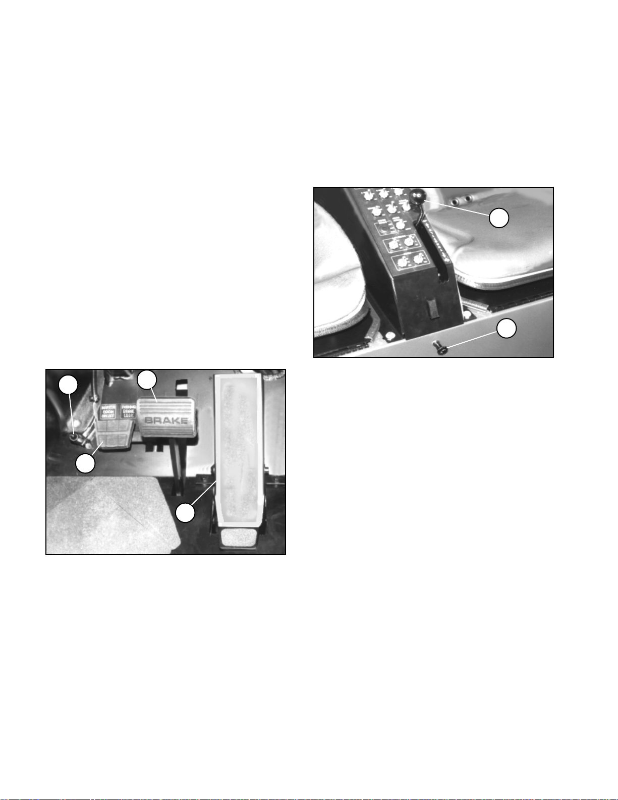
EMERGENCY/PARKING BRAKE PEDAL:
(Fig. 17) Functions as a parking brake and an
emergency brake in situations demanding an
immediate stop.
BRAKE LOCK: (Fig. 17) The small pedal to the
left side of the brake pedal actuates the parking
brake lock. To engage parking brake, fully depress
brake pedal and depress brake lock which locks
brake pedal. To release parking brake, fully
depress brake pedal to release brake lock.
"
®
5500.
THROTTLE CONTROL: (Fig. 18) Move control
forward, toward "FAST", to increase engine speed,
rearward, toward "SLOW", to decrease engine
speed. Set at 1/4 to 1/3 throttle when starting
engine.
MANUAL CHOKE: (Fig. 18) Pull OUT when
starting cold engine, gradually push IN after
successfully starting engine.
Figure 18
1. Throttle control 2. Manual Choke
!
Figure 17
1. Traction Pedal 3. Brake Lock
2. Brake Pedal 4. Remote Master Switch
REMOTE BOOM ON/OFF SWITCH: (Fig. 17) Is
in series with the MASTER BOOM ON/OFF switch;
The operator must first turn on the Master Boom
ON/OFF switch on the center console; then click
on the Remote Boom ON/OFF Switch on the floor
board.
20
Page 21

1147
VEHICLE CONTROLS
INSTRUMENT PANEL LAYOUT
SPEED CONTROL: Vehicle may be set at a
desired speed. Ground speed will vary slightly in
accordance with the slope of the terrain.
1. ENABLE BUTTON: When depressed,
activates the Speed Control.
2. TOGGLE SWITCH: Turns Speed Control
"ON" or "OFF".
3. INDICATOR LIGHT: When lit, indicates
Speed Control is on.
4. PRESSURE GAUGE: Indicates the pressure
at which the Spray System is operating
.
5. BOOM INDICATOR LIGHTS: When lit,
indicates which Boom section(s) is on.
6. PASSENGER HAND HOLD: Right side of
dash panel.
7. ENGINE OIL PRESSURE WARNING LIGHT:
Indicates dangerously low oil pressure. If light
comes on with the engine running, STOP as soon
as possible and correct the cause of low oil
pressure before restarting the engine.
8. COOLANT TEMPERATURE GAUGE:
Indicates the temperature of the engine coolant
when the ignition switch is in the ON position. The
pointer will move to the NORMAL band as the
engine warms up. When operating in hot weather
or with very heavy loads, the pointer may read at
the very top of the NORMAL band. If the pointer
moves out of the NORMAL band into the H (hot)
position, the engine is overheating and engine
damage may result. If there is no apparent loss
of coolant from the cooling system, idle the engine
for two minutes, then turn off the engine and let it
cool.
9. VOLT METER: Indicates the battery voltage
when the ignition key is in the ON position. After
the engine is started, the pointer will move into
the white marked area, and in normal operation,
remain there. (12.8-14.8 volts) If the pointer
remains in either red marked area, have the
engine's electrical system checked.
10. HOUR METER: Shows total hours that
vehicle has been operated.
11. HEADLAMP SWITCH: Turns Headlamps
ON and OFF.
12. IGNITION SWITCH: NOTE: THIS IS A FOUR
POSITION SWITCH. The "ACC" position is not
used on the MULTI PRO
®
5500 Turf Sprayer. In
the "OFF" position, the switch disconnects the
electrical system from the battery. The key can
be removed from the switch when it is in this
position. In the "ON" position, the electrical system
is activated. Engage the starter by turning the key
to the "START" position. Release the key when
the engine starts and it will return to the "ON"
position.
21
Page 22

OPERATING INSTRUCTIONS
PRE-STARTING CHECKS
Safe operation begins before taking the vehicle
out for a day's work. You should check these items
each time:
1. Check tire pressure. (See page 19)
NOTE: These tires are different than car tires,
they require less pressure to minimize turf
compaction and damage.
2. Check all fluid levels and add the appropriate
amount of TORO specified fluids if any are found
to be low.
3. Check Brake Pedal operation.
4. Check to see that the lights are working.
5. Check for oil leaks, loose parts, or any other
noticeable malfunctions. Make sure engine is off
and all moving parts have stopped before
checking for oil leaks, loose parts, and any other
malfunctions.
If any of the above items are not correct, notify
your mechanic or check with your supervisor
before taking the vehicle out for the day. Your
supervisor may want you to check other items on
a daily basis, so ask what your responsibilities are.
IMPORTANT! Do not hold Key in starting
position longer than 10 seconds at one time. If
the engine does not start, wait at least 60
seconds before attempting to start again.
Continuous cranking will burn out the Starter
motor. If the engine develops sufficient speed
to disengage the Starter, but fails to continue
running, the engine must come to a complete
stop before attempting to restart the engine. If
the Starter is engaged while the Flywheel is still
rotating, the Starter Pinion and Flywheel ring
gear may clash, resulting in damage to the
Starter. If the Starter does not turn the engine
over, shut off the engine immediately and do
not attempt to start the engine until the
condition has been corrected. Do not "jumpstart" using another, larger battery.
NOTE: Starter motors are pre-lubricated.
Brushes normally require servicing only after
extended use.
6. Gradually push the choke in to the OFF
position after the engine is running.
7. Turn Steering Wheel to the left and right to
check steering response.
8. Position the Throttle Lever at the desired
engine RPM.
STARTING ENGINE
WARNING
Engine exhaust gases contain poisonous
carbon monoxide.
Carbon monoxide is odorless, colorless
and can cause death if inhaled.
Avoid inhaling exhaust fumes and never
run the engine in a closed building or
confined area.
1. Sit on Operator's Seat and engage Parking
Brake.
2. Make sure Traction Pedal is in NEUTRAL
position.
3. Make sure Spray System is in the "OFF"
position.
3. Move the Throttle Lever 1/4 to 1/3 throttle.
4. Pull the Choke Control out to full choke
position, if cold starting engine.
DRIVING VEHICLE
1. Release Parking Brake.
2. With the operator's foot positioned on the foot
pedal as shown in (Fig. 19 page 23), slowly apply
pressure with the toe on top of the pedal away
from the operator to move in a FORWARD
direction. Position toe on the "tail" of the pedal to
move in a REVERSE direction.
3. Slowly moving the Traction Pedal to the
NEUTRAL or "centered" position will bring the
vehicle to a stop. Be sure to allow the vehicle to
stop before changing between forward and
reverse motion.
4. Use the Throttle Lever to adjust the engine
RPM if necessary.
5. Insert Key into Ignition Switch and rotate it
clockwise to start engine. Release Key when
engine starts.
22
Page 23

OPERATING INSTRUCTIONS
1148
Figure 19
A. Neutral B. Forward C. Reverse
IMPORTANT! Do not attempt to push or tow
the vehicle to get it started.
STOPPING VEHICLE
3. Depress the SET button to lock ON the Speed
Control.
4. To disengage the Speed Control, the brake
must be depressed, or the Toggle Switch turned
to the OFF position.
When the Speed Control is disengaged by use of
the Brake Pedal, the operator must depress the
SET button again to re-lock ON the Speed Control.
When the Speed Control is disengaged by use of
the Toggle Switch, the operator must flip the
Toggle Switch to the ON position and depress the
SET button to lock ON the Speed Control.
CAUTION
Turning off the Toggle Switch while using
speed control may bring the vehicle to
an abrupt stop, possibly causing
personal injury.
Always place foot on Traction Pedal
before turning Toggle Switch off.
NEW VEHICLE BREAK-IN
1. Slowly moving the Traction Pedal to NEUTRAL
will stop the vehicle.
2. The BRAKE pedal may also be used to assist
in stopping the vehicle in an emergency.
STOPPING ENGINE
1. Move Throttle Lever to "SLOW".
2. Depress Brake Pedal and lock in place by
depressing the Brake Lock Pedal .
3. Rotate Ignition Key to "OFF".
4. Remove Ignition Key from Switch to prevent
accidental starting.
SPEED CONTROL OPERATION
NOTE: The Speed Control can be engaged with
the MULTI PRO
accessories are in use.
1. Flip the Toggle Switch to the ON position to
enable the Speed Control.
®
5500 in operation and when the
Your MULTI PRO® 5500 is ready for work. To
provide the longest vehicle life, follow these
guidelines for the first 100 operating hours.
1. Check the fluid and engine oil levels regularly
and be alert for indications of overheating in any
component of the vehicle.
2. After starting a cold engine, let it warm up for
about 15 seconds before accelerating.
3. Vary vehicle speeds during operation. Avoid
excessive idling. Avoid fast starts and quick stops.
4. A break-in oil for the engine is not required.
Original engine oil is the same type specified for
regular oil changes.
5. Refer to the Maintenance section of this
Manual for any special low hour checks.
2. Depress the Traction Pedal forward until the
vehicle reaches the desired speed of operation.
23
Page 24

OPERATING INSTRUCTIONS
OPERATING CHARACTERISTICS
The vehicle is designed with safety in mind. It has
four wheels for added stability. It is important to
remember, however, that this vehicle is not a
passenger car. It is a Turf Sprayer and is not
designed for use on roadways.
The vehicle has special tires, a hydraulic traction
pedal, and other features that give it extra
gradeability. These features add to the versatility
of the vehicle but, they can also get you into
dangerous situations. You must keep in mind that
the vehicle is not a recreation vehicle. It is not an
all terrain vehicle. And, it is definitely not meant
for "stunt driving" or "horsing around". It is a Turf
Sprayer, not a play vehicle. Children should not
be allowed to operate the vehicle, or ride as a
passenger on the vehicle. Anyone who operates
the vehicle should have a motor vehicle license.
If you are not experienced at driving the vehicle,
practice driving in a safe area away from other
people. Be sure you are familiar with all the vehicle
controls, particularly those used for braking,
steering, and shifting. Learn how your vehicle
handles on different surfaces. Your operating skills
will improve with experience, but as with operating
any vehicle, take it easy as you begin. Be sure
you know how to stop quickly in an emergency. If
you need help ask your supervisor for assistance.
Many factors contribute to accidents. You have
control over several of the most important. Your
actions, such as driving too fast, turning too
sharply, and combinations of these, are frequent
causes of accidents.
One of the major causes of accidents is fatigue.
Be sure to take occasional breaks. It is very
important that you stay alert at all times.
Avoid driving when it is dark, especially in
unfamiliar areas. If you must drive when it's dark,
be sure to drive cautiously, use the headlights.
PASSENGERS
The MULTI PRO® 5500 Turf Sprayer comes
equipped with hip restraints and a passenger grab
bar. Whenever you have a passenger riding on
the vehicle, make sure he or she is holding on
securely. Drive slower and turn less sharply
because your passenger does not know what you
are going to do next and may not be prepared for
turning, stopping, accelerating, and bumps.
You should remain seated at all times, keeping
arms and legs inside the vehicle. The operator
should keep both hands on the steering wheel
whenever possible.
There should never be passengers in the Cargo
Bed or on any attachments. The vehicle is meant
to carry a driver and one passenger only, and then
only on the front seat.
SPEED
Speed is one of the most important variables
leading to accidents. Driving too fast for the
conditions can cause you to lose control and have
an accident. Speed can also make a minor
accident worse. Driving head-on into a tree at slow
speed can cause injury and damage, but driving
into a tree at high speed can destroy the vehicle
and kill you and your passenger.
Never drive too fast for the conditions. If there is
any doubt about how fast to drive, slow down.
TURNING
Never operate the vehicle, or any equipment, if
you are under the influence of alcohol or other
drugs. Even prescription drugs and cold
medicines can cause drowsiness. Read the label
on the medicine or check with your doctor or
pharmacist if you are unsure about a certain
medication.
One of the most important rules to follow is to go
slower in unfamiliar areas. It is surprising how
much damage and injury common things can
cause. Tree branches, fences, wires, other
vehicles, tree stumps, ditches, sand traps,
streams, and other things found in most parks and
golf courses can be hazardous to the operator and
passenger.
24
Turning is another important variable leading to
accidents. Turning too sharply for the conditions
can cause the vehicle to lose traction and skid, or
even tip over.
Wet, sandy, and slippery surfaces make turning
more difficult and risky. The faster you are going,
the worse this situation becomes so, slow down
before turning.
During a sharp turn at higher speeds, the inside
rear wheel may lift off the ground. This is not a
flaw in the design, it happens with most four wheel
vehicles including passenger cars. If this happens,
you are turning too sharply for the speed at which
you are traveling. Slow down!
Page 25

OPERATING INSTRUCTIONS
BRAKING
The MULTI PRO® 5500 Turf Sprayer has a
hydrostatic braking system, which means that
when the vehicle is not being propelled into motion
it is stopped. The vehicle will not coast under
normal operation.
It is good practice to slow down before
approaching an obstacle. This gives you extra
time to stop or turn away. Hitting an obstacle can
damage the vehicle and its contents. More
importantly, it can injure you.
Gross vehicle weight has a major impact on your
ability to stop and/or turn. Heavier loads and
heavier attachments make a vehicle harder to stop
or turn. The heavier the load, the longer it takes
to stop.
The braking characteristics also change with no
bed or attachments on the vehicle. Fast stops
may cause the rear wheels to lock up, which may
affect the control of the vehicle. Its a good idea to
decrease the vehicle speed with no bed or
attachments.
Turf and pavement are much more slippery when
wet. It can take 2 to 4 times as long to stop on wet
surfaces as on dry surfaces.
NOTE: Heavy loads and turf conditions affect
your vehicle's brake performance and ability
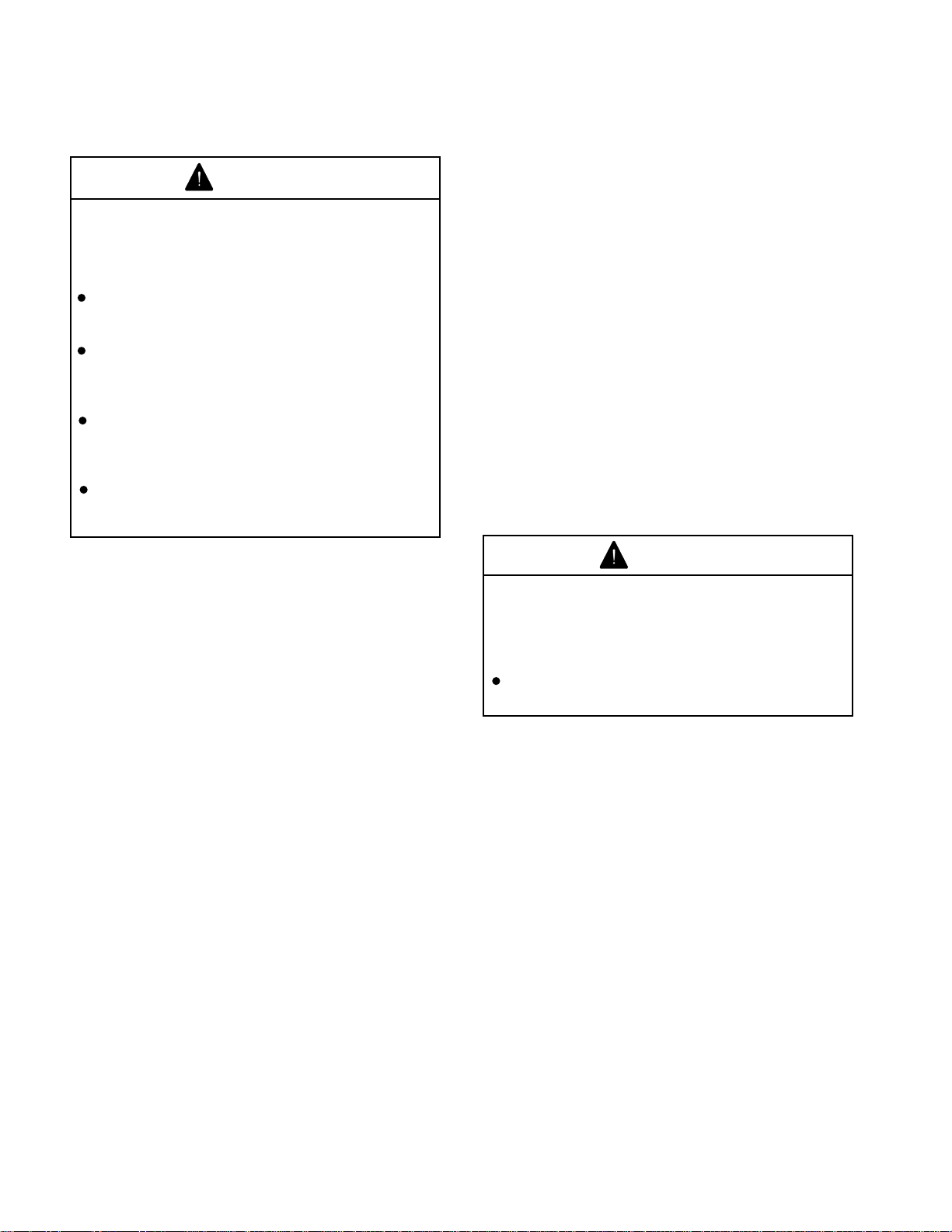
to turn quickly without tipping over.
TIPOVERS
The best way to prevent accidents involving Turf
Sprayer is through continuous supervision and
training of operators and paying constant attention
to the area in which the vehicle is being operated.
The best way for operators to prevent serious injury
or death to themselves or others is to familiarize
themselves with the proper operation of the Turf
Sprayer, to stay alert and to avoid action or
conditions which could result in an accident. In
the event of a tip over, the risk of serious injury or
even death will be reduced if the operator and all
involved follow the instructions provided.
WARNING
1149
Tipping or rolling the vehicle could cause
serious personal injury or death.
If engine stalls or you lose momentum
on a hill, never attempt to turn vehicle
around.
When backing down a hill always back
straight down.
Never drive across a steep hill, always
drive straight up or down.
Avoid turning on a hill.
HILLS
Use extra care when on hills. Never go on hills
that are extremely steep. Stopping while going
down a hill will take longer than on level ground.
Turning while going up or down a hill is more
dangerous than turning on the level. Turning while
going down hill, especially with the brakes on, and
turning up hill while traversing a hill, are particularly
dangerous. Even at a slow speed and without a
load, tipovers are more likely if you turn on a hill.
Do not accelerate while climbing or descending a
hill. If you have to turn while on a hill, do it as
slowly and cautiously as possible. Never make
sharp or fast turns on a hill.
If you stall or begin to lose headway while climbing
a hill, quickly apply the brakes, engage emergency
brake, and restart the engine.
25
Page 26

OPERATING INSTRUCTIONS
TOWING VEHICLE
In an emergency the MULTI PRO® 5500 can be
towed a short distance by actuating the dump
valve in the variable displacement hydraulic pump,
and towing the vehicle. However, TORO does not
recommend this as a standard procedure.
IMPORTANT! Do not tow the vehicle faster than
2-3 mph (3-4.8 km/hr) because internal
transmission damage may occur. The dump
valve must be open whenever the vehicle is
pushed or towed. If the vehicle must be moved
a considerable distance, transport it on a truck
or trailer.
Note: When the engine is not running, the
power steering will not function, making it
difficult (increased effort) to steer.
CAUTION
Towing at excessive speeds could cause
vehicle to lose steering control.
Never tow vehicle faster than 3 MPH.
DUMP VALVE (Fig. 20)
1. The Dump Valve is located on the left side of
the variable displacement pump. Rotate the valve
90° in either direction to open. This will allow
hydraulic fluid to by-pass internally. When fluid is
by-passed, the vehicle can be moved - slowly without damaging the transmission.
2. Close dump valve before starting the engine.
However do not exceed 5-8 ft-lb (7-11 N m) torque
to close the valve.
Figure 20
MAINTENANCE
WARNING
Servicing the vehicle while the engine is
running or vehicle is not properly secured,
could result in personal injury or death.
Before servicing or making adjustments
to the vehicle, set parking brake, stop
engine, and remove key from the switch.
1. Dump Valve
(shown in normal position)
Establish a regular schedule of lubrication to insure
trouble free performance.
For a vehicle operated under normal conditions,
check and service at the intervals indicated in the
chart on the following page. When operating in
extremely cold, hot, or dusty conditions, check and
service more frequently. For additional engine
maintenance information, refer to the Engine
Operator's Manual supplied with the vehicle.
26
Page 27

DAILY MAINTENANCE SCHEDULE
Daily Maintenance: (duplicate this page for routine use)
Check proper section of Operator's Manual for fluid specifications.
Maintenance Daily Maintenance Check For Week Of
Check Item MON TUES WED THURS FRI SAT SUN
Neutral Lockout Switch Operation
ü
Emergency/Park Brake Operation
ü
Engine Oil and Fuel Level
ü
Cooling System Fluid Level
ü
Dust Cup and Baffle (Air Filter)
ü
Radiator and Oil Cooler for Debris
ü
Unusual Operating Noises
ü
Unusual Engine Noises
ü
Hydraulic System Oil Level
ü
Hydraulic Hoses for Damage
ü
Fluid Leaks
ü
Tire Pressure
ü
Instrument Operation
ü
Sprayer Hose Clamp Connections
ü
Lubricate All Grease Fittings*
Touch-up Damaged Paint
* Perform immediately after every washing regardless of the interval listed.
Notation for areas of concern: Inspection performed by
Item Date Information
1
2
3
4
5
6
7
8
9
10
Check proper section of Operator's Manual for fluid specifications.
27
Page 28

MAINTENANCE SCHEDULE
Minimum Recommended Maintenance Intervals:
Maintenance Procedure
Inspect Air Filter, Dust Cap, and Baffle
Lubricate All Grease Fittings
Check Battery Fluid Level
Check Battery Cable Connections
Change Engine Oil and Filter
**
Inspect Cooling System Hoses
Check Fan and Alternator Belt Tension
*
Service Air Filter
Replace Hydraulic Filter
*
Check Front Wheel Toe-In and Steering Linkage
Torque Wheel Lug Nuts
*
Check Governor Oil Level
Lubricate Throttle and Governor Linkage
Solenoid Valve Maintenance
Maintenance Interval & Service
Every
400 hrs.
Every
50 hrs.
"A" Level
Service
Every
100 hrs.
"B" Level
Service
"C" Level
Every
200 hrs.
Service
Change Fuel Filters
Inspect Fuel Lines and Connections
Check Rear Planetary Gear Lube
Change Hydraulic Oil
Change Hydraulic Oil Filter
*
Flush Cooling System and
Replace Coolant
Drain and Clean Fuel Tank
Change Rear Planetary Gear Lube
Pack Front Wheel Bearings
Initial break-in at 10 hours
*
Initial break-in at 50 hours
**
Initial break-in at 200 hours
Recommendations:
Items listed are recommended every 800
hours or 2 years, whichever occurs first.
"D" Level
Service
Replace Safety Switches
28
Page 29

JACKING VEHICLE
1. Do not start engine while vehicle is on jack,
because engine vibration or wheel movement
could cause vehicle to slip off jack.
2. Do not work under vehicle without jack stands
supporting it. The vehicle could slip off the jack,
injuring anyone beneath it.
3. The jacking points at the front of the vehicle
are under the front axle directly beneath the leaf
springs. (Fig. 21)
4. The rear jacking points are on the rearmost
frame support, between the angle welds. (Fig. 22)
5. Always chock or block wheels opposite the
side which is being jacked.
Figure 21
1. Front Jacking Points
Figure 22
1. Rear Jacking Points
29
Page 30

LUBRICATION
WARNING
Servicing the vehicle while the engine is
running or vehicle is not properly secured,
could result in personal injury or death.
Before servicing or making adjustments
to the vehicle, set parking brake, stop
engine, and remove key from the switch.
The MULTI PRO® 5500 has 11 grease fittings that
must be lubricated regularly with No. 2 General
Purpose Lithium Base Grease. If the machine is
operated under normal conditions, lubricate all
bearings and bushings every 100 hours of
operation. More frequent lubrication is required if
used for heavy duty vehicle operations.
The grease fitting locations and quantities are: Tie
rod ends (2), Power steering cylinder (2), Front
spindles (2), Drive linkage arms (2), Boom hinges
(2), Governor lever (1). (See Fig. 23-26)
Figure 24
1. Neutral Centering Arm Fittings (one on each arm)
1. Wipe grease fitting clean so foreign matter
cannot be forced into the bearing or bushing.
2. Pump grease into the bearing or bushing.
3. Wipe off excess grease.
!
Figure 23
1. Steering Cylinder Fitting (one shown; one at other
end of cylinder)
2. Tie Rod End Fitting (one on each side)
Figure 25
1. Boom Hinge Fitting (one on each side)
Figure 26
1. Governor Lever Fitting
30
3. King Pin Fitting (one on each side)
Page 31

AIR CLEANER MAINTENANCE
WARNING
Servicing the vehicle while the engine is
running or vehicle is not properly secured,
could result in personal injury or death.
Before servicing or making adjustments
to the vehicle, set parking brake, stop
engine, and remove key from the switch.
2. Remove Wing nut from the Air Filter guide
bolt, and gently slide the Air Filter out of the
Air Cleaner Body. Avoid knocking filter against
Air Cleaner Body to reduce amount of dust
dislodged.
3. Wipe inside of the Air Cleaner Body with
a damp rag.
4. Inspect Air Filter, replace if damaged.
A. Place a bright light inside of filter.
GENERAL AIR CLEANER
MAINTENANCE PRACTICES
Inspect the Air Cleaner and Hoses periodically to
maintain maximum engine protection and to
ensure maximum service life. Extensive damage
can result from operating with a dirty Air Cleaner.
1. Check Air Cleaner Body for dents and other
damage which could possibly cause an air leak.
Replace a damaged Air Cleaner Body.
2. Squeeze the Vacuator Valve to eject dust and
water.
3. Service the Air Cleaner Filter every 100 hours
(more frequently in extremely dust conditions.)
4. Be sure Dust Cup is sealing around Air
Cleaner Body.
SERVICING AIR CLEANER FILTER
(Fig. 27)
1. Loosen the Strap that is securing Dust Cup
to Air Cleaner Body. Remove the Dust Cup from
body. Clean inside of Dust Cup.
B. Rotate filter slowly while checking for dirt,
ruptures, holes, and tears.
C. Check fin assembly, gasket, and screen
for damage.
5. Clean a reusable element by washing it, or
blow out dirt by using compressed air. Do not
reuse a damaged filter.
WASHING METHOD:
NOTE: Do not remove plastic fin assembly.
Washing will remove dust from beneath fins.
A. Prepare a solution of filter cleaner and
water and soak filter element approximately
15 minutes. Refer to directions on filter
cleaner carton for complete information.
B. After soaking, rinse with clear water.
Maximum water pressure must not exceed 40
psi to prevent damage to the filter element.
Rinse filter from clean side to dirty side.
C. Dry filter using, warm flowing air (160°F
max), or allow element to air dry. Do not use
compressed air or light bulb to dry the filter
element because damage could result.
Figure 27
1. Vacuator valve 4. Filter element
2. Dust cup 5. Air cleaner strap
3. Mounting bands 6. Inlet hood
COMPRESSED AIR METHOD:
NOTE: Do not remove plastic fin assembly.
Back-blowing with compressed air removes
dust from beneath fins.
A. Blow compressed air from inside to
outside of filter element. Do not exceed 100
psi. (Wear eye protection)
B. Keep air hose nozzle at least 1 inch from
pleated paper, and move nozzle up and down
while rotating the filter. Inspect filter when dust
and dirt are removed.
6. Inspect a replacement filter for any shipping
damage. Install the new filter and secure the Wing
nut, Dust Cup, and Air Cleaner Strap.
7. Check all ducting, hoses, and clamped
connections for leaks.
31
Page 32

ENGINE MAINTENANCE
WARNING
Servicing the vehicle while the engine is
running or vehicle is not properly secured,
could result in personal injury or death.
Before servicing or making adjustments
to the vehicle, set parking brake, stop
engine, and remove key from the switch.
ENGINE OIL
SINGLE VISCOSITY OILS
Outside Temperature
- 10°F to +60°F SAE 10W
+10°F to +90°F SAE 20W-20
Above +32°F SAE 30
Above +50°F SAE 40
MULTI-VISCOSITY OILS
CHANGING ENGINE OIL AND FILTER
(Fig. 28)
Change oil and filter after the first 50 hours of
operation, thereafter change oil and filter every 100
hours.
WARNING
Continuous contact with used motor oil
has caused skin cancer in laboratory
mice.
Do not handle a hot oil filter with bare
hands.
Protect your skin by washing with soap
and water.
1. Remove drain plug and let oil flow into a drain
pan. When oils stops, install drain plug.
Outside Temperature
Below +60°F SAE 5W-30
- 10°F to +90°F SAE 10W-20
Above -10°F SAE 10W-40 or 10W50
Above +50°F SAE 20W-40 or 20W50
OIL FILTER
This vehicle requires the use of a Motorcraft FL-313
Long-Life Oil Filter. This filter has an oil bypass
valve in it.
IMPORTANT! ALL 5500 vehicles model no.
80001 and up MUST use the Motorcraft FL-313
oil filter or engine damage WILL occur.
Motorcraft
FL-313
Figure 28
1. Engine Oil 2. Engine Oil Filter
Drain Plug
2. Remove oil filter. Apply light coat of clean oil
to the seal of the new oil filter before screwing it
on. Hand tighten until the gasket contacts the
base, then tighten 1/2 to 2/3 turn. DO NOT
OVERTIGHTEN.
3. Add recommended oil to crankcase. Capacity
is 3.5 quarts (3.25 Liter) with filter.
32
GOVERNOR MAINTENANCE
For Governor maintenance refer to the instructions
provided in the
Operator's Manual. (Supplied with vehicle)
Ford Engine Maintenance and
WARNING
Carelessly performing adjustments to a
running engine could cause personal
injury.
Engage parking brake and keep hands,
feet, face, and other parts of the body
away from fan and other moving parts.
Page 33

ENGINE MAINTENANCE
WARNING
Servicing the vehicle while the engine is
running or vehicle is not properly secured,
could result in personal injury or death.
SPARK PLUGS (Fig. 30)
For specifications refer to the Ford Engine
Maintenance and Operator's Manual. (Supplied
with vehicle)
Before servicing or making adjustments
to the vehicle, set parking brake, stop
engine, and remove key from the switch.
IMPORTANT! Check fuel lines and connections
every 400 hours. Inspect for deterioration,
damage, or loose connections.
FUEL FILTERS (Fig. 29)
The MULTI PRO® 5500 is equipped with two fuel
filters. One is an in-line type located between the
fuel tank and fuel pump. The other is a threaded
filter located between the fuel pump and
carburetor. Replace filters every 400 hours of use.
In-line:
1. Remove the inlet and outlet hose clamps.
2. Disconnect the hoses and discard the filter.
3. Install new filter by connecting the hose from
the fuel tank to the inlet side and the hose from
the fuel pump to the outlet side.
4. Position the hose clamps and tighten.
Threaded:
1. Loosen and slide hose clamp down the fuel
line. Remove the line from the filter.
2. Use 15/16" wrench to remove filter from elbow
and discard old filter.
Replace spark plugs at recommended intervals.
Maintenance of spark plugs is an important factor
in assuring proper engine performance and
reducing the exhaust emission level.
The MULTI PRO
or AGRF22 or equivalent Spark Plugs with air gap
set as specified.
1. Remove wires from each Spark Plug by
grasping, twisting, and then pulling the molded
boot of the wire only. Do not pull directly on the
wire because the wire connection inside the boot
may become separated.
2. After loosening each Spark Plug one or two
turns, clean the area around each Spark Plug port
with compressed air, then remove Spark Plugs.
3. Check condition of side electrode, center
electrode, and center electrode insulator. Replace
spark plugs if damage is evident.
IMPORTANT! A CRACKED, FOULED, DIRTY,
OR OTHERWISE MALFUNCTIONING SPARK
PLUG MUST BE REPLACED. DO NOT
ATTEMPT TO SAND BLAST, SCRAPE, OR
CLEAN ELECTRODES WITH A WIRE BRUSH
BECAUSE GRIT MAY EVENTUALLY RELEASE
FROM THE PLUG AND CAUSE ENGINE
DAMAGE.
4. Set gap between center and side electrodes
as specified. Install correctly gapped Spark Plug
and torque (tighten) plug as specified.
®
5500 uses Motorcraft-AGSF 22C
3. Thread new filter and tighten securely. DO
NOT OVERTIGHTEN.
4. Install fuel line to new filter and secure with
hose clamp.
Note: After replacing fuel filters start the engine
and check for leaks.
Figure 29
1. Inline filter 2. Threaded filter
5. Connect Spark Plug wires securely.
NOTE: Do not overtighten plugs. The gap may
change considerably due to the distortion of
the plug outer shell.
Figure 30
1. Spark Plugs
33
Page 34

COOLING SYSTEM MAINTENANCE
CAUTION
Coolant in a hot radiator is under extreme
pressure. Scalding hot coolant or steam
can blow out of the radiator, causing
serious injury.
3. Open coolant drain cock at bottom of radiator
and allow coolant to flow into drain pan. When
coolant stops, close drain cock. (Fig. 31)
4. Slowly fill radiator with a 50/50 mixture of water
and recommended coolant. Install the radiator
cap securely.
Never remove the radiator cap, under any
conditions, when the engine is running.
Never remove the radiator cap when the
engine or radiator are hot.
IMPORTANT! NEVER SPRAY WATER ONTO A
HOT ENGINE AS DAMAGE MAY OCCUR.
IMPORTANT! NEVER ADD COOLANT TO AN
ENGINE THAT HAS BECOME OVERHEATED,
UNTIL THE ENGINE HAS COOLED. ADDING
COOLANT TO AN EXTREMELY HOT ENGINE
CAN RESULT IN A CRACKED BLOCK OR
CYLINDER HEAD.
Whenever coolant level checks are made check
condition of the rubber seal on the Radiator Cap.
Make sure the Radiator Filler Neck and Cap are
clean and rinsed free of any dirt particles.
The cooling system has a total capacity of 12
quarts (11.5 liters). A 50/50 mix of anti- freeze and
clean water is recommended.
Maintain the coolant level at approximately 3/4 to
1-1/2 inches below the Filler Neck seat on the
Radiator when the coolant is cold.
5. Start engine and operate until warm. Recheck
level and replenish, if required.
Use only a permanent-type coolant that meets
Ford Specification ESE-M97B44-A. Refer to the
coolant mixture chart on the container for
additional antifreeze protection information. Do
not use alcohol or methanol antifreeze.
Every 200 hours (more often in dusty areas)
inspect the exterior of the radiator and oil cooler
for obstructions. Remove all bugs, dirt, or foreign
material with a soft brush or cloth. Use care to
avoid damaging the fins. If available, use low
pressure compressed air or a stream of water in
the opposite direction of normal air flow.
Check all hoses and connections for leaks. If any
of the hoses are cracked, frayed, or feel spongy,
they should be replaced.
Remove debris from engine area, oil cooler, and
radiator daily, clean more frequently in dirty
conditions.
CHANGING ENGINE COOLANT
(Fig. 31)
CAUTION
If engine has been running, pressurized
hot coolant can escape and cause burns
if cap is removed.
Before removing cap, allow engine to
cool for at least 15 minutes or until the
cap is not hot to the touch.
1. Park vehicle on level surface.
2. Remove radiator cap (ONLY IF IT IS COOL
TO THE TOUCH!)
34
Figure 31
1. Radiator Drain Cock
Page 35

BELT MAINTENANCE
DRIVE BELTS
The drive belts should be properly adjusted at all
times. A loose drive belt causes improper
alternator, fan and water pump operation, in
addition to overheating. Overtightening the belt
may result in excessive wear on the alternator and
water pump bearings, as well as premature wear
on the belt itself. Therefore, it is recommended
that a belt tension gauge be used to check and
adjust the belt tension. Any belt that has
operated for a minimum of 10 minutes is
considered a used belt, and when adjusted, it
must be adjusted to the reset tension shown in
the specifications below:
Belt Tension Specifications
Alternator Tension
New 79-101 lbs.
Used-Reset Minimum 56-75 lbs.
Governor
New 75 lbs.
Used-Reset Minimum 50 lbs.
A used belt is one that has been in operation for 10
minutes or more. Reset belt tension when it meets
minimum specification.
ADJUSTING BELTS
3. Hold alternator in position after proper belt
tension setting is achieved and tighten alternator
and brace bolts to secure adjustment.
Governor/Cooling Fan Belt (Fig. 33)
1. To adjust belt tension, loosen upper and lower
nuts securing idler arm to front engine mount.
Figure 33
1. Governor/Fan Belt Mounting Bolts
2. Pull out on idler arm until desired belt tension
is achieved.
Check tension of all belts initially after the first day
of operation and every 100 hours thereafter.
Alternator Belt (Fig. 32)
Figure 32
1. Alternator Belt 2. Mounting Bolts
1. To adjust belt tension, loosen bolt securing
alternator brace to engine, bolt securing alternator
to brace and alternator mounting bolt.
3. Tighten mounting nuts to secure adjustment.
2. Insert pry bar between alternator and engine
and pry out on alternator.
35
Page 36

HYDRAULIC SYSTEM MAINTENANCE
CHANGING HYDRAULIC FLUID
Change hydraulic fluid after every 400 operating
hours, in normal conditions. If fluid becomes
contaminated, contact your local TORO distributor
because the system must be flushed.
Contaminated fluid looks milky or black when
compared to clean oil.
1. Start engine, park machine on a level surface,
set the parking brake, and shut engine off. Block
the two rear wheels.
2. Clean area around hydraulic oil filter and
remove filter.
3. Clean area around one hydraulic line on
bottom of tank. Loosen and remove line from tank
fitting and allow oil to flow into drain pan.
4. Install new filter; refer to steps 1-2 in
"Replacing Hydraulic Oil Filter", for proper
procedures.
5. Reinstall hydraulic line on tank fitting and
tighten securely.
2. Clean area around filter mounting area. Place
drain pan under filter and remove filter.
3. Lubricate new filter gasket, and fill the filter
with recommended hydraulic fluid.
4. Make sure filter mounting area is clean. Screw
filter on until gasket contacts mounting plate. Then
tighten filter 1/2 to 2/3 turn.
5. Start engine and let run for about two minutes
to purge air from the system. Stop the engine,
check the hydraulic oil level, and check for leaks.
CHECKING HYDRAULIC LINES AND
HOSES
CAUTION
Pin hole leaks can eject high pressure
hydraulic fluid. Hydraulic fluid escaping
under pressure can penetrate skin and
cause injury.
6. Fill reservoir with approximately 12 gallons of
hydraulic fluid. Refer to "Checking Hydraulic
Fluid". (page 18)
IMPORTANT! Use only hydraulic fluids
specified. Other fluids could cause system
damage.
7. Install reservoir cap. Start and run engine at
idle speed for about two minutes and turn the
steering wheel lock to purge air trapped in the
system. Turn the engine off.
8. Check level of fluid and add enough to raise
level to specified level. DO NOT OVERFILL.
REPLACING HYDRAULIC OIL FILTER
IMPORTANT! KEEPING THE HYDRAULIC
SYSTEM CLEAN IS ESSENTIAL. SERVICING
THE HYDRAULIC FILTER IS CRITICAL TO THE
LIFE OF THE HYDRAULIC SYSTEM.
The hydraulic filter keeps the hydraulic system
relatively free of contaminants and must be
serviced at regular intervals. Initially, change filter
after first ten hours of engine operation, and
thereafter every 200 hours of operation or
yearly, whichever comes first. Use TORO oil
filter, Part No. 86-3010, as a replacement.
Fluid accidentally injected into the skin
must be surgically removed within a few
hours by a doctor familiar with this form
of injury or gangrene may result.
Wear gloves and use cardboard or
paper to find hydraulic leaks.
Inspect hydraulic lines and hoses daily for leaks,
kinked lines, loose mounting supports, wear, loose
fittings, weather deterioration, and chemical
deterioration. Make all necessary repairs before
operating.
1. Position vehicle on a level surface, stop
vehicle, engage parking brake (lock), turn engine
off, and remove key from ignition switch.
36
Page 37

HYDRAULIC TANK
(13 GPM VAC.)
(5.8 GPM VAC)
HYDRAULIC SYSTEM DIAGRAM
WHEEL
MOTOR
(275 PSI)
(= CHARGE PUMP)
(0 - 4000 PSI)
MAIN PRESSURE
FLOW DURING
FORWARD MOTION
(0 - 17 GPM MAX)
(0 - 20 PSI)
CASE DRAIN
RETURN FLOW
(5.8 GPM
@ 275 PSI)
TO REMOTE
CHARGE PORT
GEAR
PUMP
FLOW DURING
FORWARD MOTION
FILTER
PUMP
CHARGE
PRESSURE
SECONDARY
FLOW
(9.5 GPM)
WHEEL
MOTOR
CONTROL
HYDRAULIC
VALVE
DIRECTIONAL
P
P = PRESSURE
CF = CONTROLLED
CF
VALVE
P
(9.5 GPM)
(0 - 1500 PSI)
(850 PSI NOMINAL SPRAYER)
A
FLOW
BP = BYPASS
(0 - 9.5 GPM)
BP
(9.5 GPM)
(0 -75 PSI)
MOTOR
HYDRAULIC
SPRAY
PUMP
1152
(0 - 20 PSI)
MAIN RETURN
(12.5 GPM)
FLOW DIAGRAM
5500 HYDRAULIC
(0 - 20 PSI)
AT FULL 3200 RPM,
FORWARD MOTION,
FLOWS SHOWN ARE
TURNING TO THE RIGHT.
LOWER
UPPER
PISTON
PUMP
FORD
1.3 LITER
RADIATOR
OIL
PSI)
(0 - 20
ENGINE
COOLER
VALVE
(1500 PSI)
RELIEF
PRIORITY FLOW
(0 - 75 PSI)
(3 GPM)
(0 - 1000 PSI)
(3 GPM)
T
(0 - 75 PSI)
(9.5 GPM)
B
For optional
Dump Bed
RIGHT TURN
FLOW DURING
STEERING CYLINDER
P
L
R
GEAR
STEERING
T
T = TANK
R = WORKING PRESSURE
All Pressures and Flow Rates Shown are Nominal, After Initial Warm Up
L = WORKING PRESSURE
P = PRESSURE
37
Page 38

HYDRAULIC SYSTEM
TEST PORTS (Fig. 34,35)
The test ports are used to test pressure in the
hydraulic circuits. Contact your local TORO
Distributor for assistance.
1. Auxiliary Port is located on left side of piston
pump and is used to measure the charge pressure
of the transmission. (Fig. 34)
2. Loosen and remove the Relief Valve and
Swivel Assembly from the Adapter Fitting in left
side of Piston Pump. (Fig. 34)
3. Connect the Pressure Gauge at Adaptor to
check case drain pressure. (Fig. 34)
4. System pressure Test Ports. (Fig. 35)
NOTE: When testing the system pressure
check system at LOAD and NO LOAD
conditions.
PRESSURE SETTINGS:
Operating Pressure 0 - 1500 psi
Case Pressure 1.7 bar (25 psi) max.
Charge Pressure 17.24 to 20.68 bar
(250 to 300 psi)
System Pressure 344 bar (4000 psi)
max. intermittent
207 bar (3000 psi)
continuous rated
The high pressure relief valves used in the MULTI
®
PRO
5500 are all factory preset at 4000 psi and
cannot be readjusted.
GAUGES RECOMMENDED:
System Pressure Gauge 700 bar (5,000 psi)
Charge Pressure Gauge 0 - 50 bar (0 to 500 psi)
Figure 34
1. Auxiliary Test Port 2. Adaptor Fitting
Case Pressure Gauge 0 - 25 bar (0 to 100 psi)
38
Figure 35
1. Test Ports
Page 39

BRAKE MAINTENANCE
ADJUSTING EMERGENCY/PARK
BRAKE (Fig. 36)
Adjust the service brakes when there is more than
one inch of "free travel" of the brake pedal, or when
the brakes do not work effectively. Free travel is
the distance the brake pedal moves before braking
resistance is felt.
To reduce free travel of brake pedal:
1. Loosen front nuts on threaded end of brake
cables.
2. Tighten rear nuts to move cable backward
until the pedal has 1/2 to 1 inch of free travel.
3. Tighten front nuts after brake is adjusted
correctly.
NOTE: Both brake cables must be adjusted
simultaneously so that the brake equalizer is
straight after adjustment is made.
THROTTLE LEVER TENSION
ADJUSTING THROTTLE LEVER
TENSION (Fig. 37)
If the Throttle Lever has a tendency to creep away
from the "FAST" setting, the Throttle Pivot lock nut
may need to be tightened:
Figure 36
1. Front Nuts 2. Rear Nuts
1. Position vehicle on a level surface, stop
vehicle, engage parking brake (lock), turn engine
off, and remove key.
2. Remove the Throttle Lever knob and Console
Cover.
3. Tighten Throttle Pivot lock nut.
4. Replace console cover and Throttle Lever
knob. NOTE: Be sure to return the Throttle Lever
to the "Slow" or starting position prior to starting
engine.
Figure 37
1. Throttle Handle 2. Pivot Lock Nut
39
Page 40

AXLE MAINTENANCE
CHANGING PLANETARY GEAR
DRIVE OIL (Fig. 38,39)
Change oil initially after 200 hours operation and
every 800 hours or yearly. Check oil level if external
leakage is noted. (Refer to "Before Operating"
page 19.) Use high quality SAE 85W-140 wt. gear
lube replacement.
Capacity of each hub is 16 oz.
1. With machine on level surface, position wheel
so the check/drain plugs are at the 3 and 6 o'clock
positions. (Fig. 38 position 1.)
2. Remove both plugs. Allow oil to drain from
the bottom hole into a pan.
3. Remove drain plug from bottom of hub on
other side of wheel and allow oil to drain into pan.
(Fig. 39)
4. When Gear Drive is completely drained,
reinstall plug on bottom of hub and position wheel
so holes are at 9 and 12 o'clock position. (Fig. 38
position 2.)
5. Add gear oil to the 12 o'clock positioned hole.
Fill until the 9 o'clock hole begins to overflow.
6. Reinstall the Check/Drain plugs.
7. Repeat steps 1 thru 6 on opposite gear
assembly.
Figure 39
1. Check/Drain Plug
FRONT WHEEL TOE-IN (Fig. 40,41)
After every 600 operating hours or annually, check
front wheel toe-in.
1. Measure center-to-center distance (at axle
height) at front and rear of steering tires. Front
measurement must be 1/8 to 1/4 inch less than
rear measurement. (Fig. 40)
Center-to-center
Distance
Figure 40
40
1153
Figure 38
1. Position of Plugs 2. Position of Plugs
for draining oil. for filling with oil.
2. To adjust, loosen jam nuts at both ends of the
tie rod. (Fig. 41)
Figure 41
1. Tie Rod (one nut on each end)
3. Rotate tie rod to move front of tire inward or
outward.
4. Tighten tie rod jam nuts when adjustment is
correct.
Page 41

ELECTRICAL MAINTENANCE
JUMP STARTING PROCEDURE
1. Connect a jumper cable between the positive
(+) battery posts of the two batteries. The positive
posts may be identified by a "+" sign on the top of
the battery covers.
2. Connect one end of the other jumper cable to
the negative (-) terminal of the battery in the other
vehicle. The negative terminal has a "-" sign or
NEG on the battery cover. DO NOT connect the
other end of the jumper cable to the negative (-)
post of the discharged MULTI PRO
Connect it to the engine. DO NOT connect the
jumper cable to the fuel system.
3. Start the engine of the vehicle providing the
jump start. Let it run for a few minutes, then start
the MULTI PRO
4. Remove the negative (-) jumper cable first from
the MULTI PRO
battery in the other vehicle.
5. Finally, remove the remaining cable from both
batteries.
®
5500 engine.
®
5500 engine, then from the
®
5500 battery.
WARNING
Jump starting can be dangerous. To
avoid personal injury or damage to
electrical components in vehicle,
observe the following warnings:
Never jump start with a voltage source
greater than 15 volts D.C. This will
damage the electrical system.
Never attempt to jump start a discharged
battery that is frozen. It could rupture
or explode during jump starting.
Observe all battery warnings while jump
starting your vehicle.
Be sure your vehicle is not touching the
jump start vehicle.
Connecting cables to the wrong post
could result in personal injury and/or
damage to the electrical system.
FUSES (Fig. 42)
30
1154
MAIN ACC. ACC. SPRAY SYS.
Figure 42
20
BATTERY CARE
1. Battery electrolyte level must be properly
maintained and the top of the battery kept clean.
If the vehicle is stored in a location where
temperatures are extremely high, the battery will
run down more rapidly than if the vehicle is stored
in a location where temperatures are cool.
2. Keep top of battery clean by washing
periodically with a brush dipped in ammonia or
bicarbonate of soda solution. Flush the top
surface with water after cleaning. Do not remove
fill cap while cleaning.
3. Battery cables must be tight on terminals to
provide good electrical contact.
4. If corrosion occurs at terminals. Remove
battery cover, disconnect cables, negative (-)
cables first and scrape clamps and terminals
separately. Reconnect cables positive (+) cable
first and coat terminals with petroleum jelly.
5. Check the electrolyte level every 50 operating
hours, or if machine is in storage, every 30 days.
6. Maintain cell level with distilled or
demineralized water. Do not fill cells above the
bottom of the ring inside each cell.
CAUTION
Electrolyte gases are explosive and can
cause serious injury to eyes, lungs and
skin. Nausea may result if the gases are
inhaled.
Wear safety goggles and rubber gloves
when working with electrolyte or battery.
Charge the Battery in a well ventilated
place so gases produced while charging
can dissipate.
There are two 30 amp fuses in the vehicle's
electrical system. The fuse box is located under
the left operators seat.
The 5 amp in-line fuse located under the dash
panel on the left side, is for the speed control
feature.
Unplug charger from electrical outlet
before connecting to or disconnecting
charger leads from battery posts.
Since the gases are explosive, keep
open flames and electrical spark away
from the battery; DO NOT SMOKE!
41
Page 42

VEHICLE ELECTRICAL DIAGRAM
SPEED
CONTROL
COIL
LIGHT
BLACK
BROWN
BRAKE
SWITCH
BROWN
GREEN
WHITE
GREEN
RED
WHITE
123
DIODE
RED
5 AMP
FUSE
SPEED CONTROL
WIRING HARNESS
TOGGLE
SWITCH
RED
RED
BLUE
HOUR
METER
++
RED
METER
--
GREEN/RED
IGN
ST
ACC
BAT
KEY
SWITCH
WIRING HARNESS
PUSH
BUTTON
ACCESSORY
SOLENOID
510 ohms
1/2 watt
RED
RESISTOR
20 AMP
20 AMP
30 AMP
30 AMP
MAIN FUSE
FUSE
BLOCK
VOLT
BLACK
GREEN/RED
GREEN/RED
RED/GREEN
RED/BLUE
YELLOW
ORANGE
VEHICLE
(Pro Control)
GREEN/RED
GREEN/RED
ACCESSORIES:
ACTUATOR
RED
SPRAY SYSTEM
FOAM MARKER
ORANGE
RED
RED
COOLANT
TEMP.
+
s
RED/WHITE
YELLOW
YELLOW
BLACK
OIL
PRESSURE
LIGHT
-
GREEN/RED
LEFT
HEADLIGHT
BLACK
WHITE/RED
ORANGE
HEADLIGHT
RED/BLUE
RED/BLUE
NEUTRAL
SWITCH
SWITCH
START
WHITE
WHITE
12-VOLT
BATTERY
RED
SOLENOID
SERVO
PUMP
RIGHT
HEADLIGHT
BLACK
WHITE
BLACK
42
1155
GROUND
TERMINAL BLOCK
RED
to Tachometer
to Alternator
unused
YELLOW
BLACK
RED/GREEN
GREEN/RED
RED/BLUE
RED/WHITE
YLW/BLACK
WHITE/RED
YELLOW
1234567891011
YLW JUMPER
TERMINAL PLATE
STARTER
MOTOR
Page 43

TRACTION DRIVE MAINTENANCE
LINKAGE MAINTENANCE (FIG. 43)
It is very important that the foot pedal operate freely
and return positively to the NEUTRAL or
CENTERED position. Periodic maintenance of the
traction pedal requires applying grease to the
grease fittings on the linkage control arms as
shown in Fig. 43.
LINKAGE TROUBLESHOOTING
(FIG. 43)
If the traction pedal fails to operate smoothly and
freely, or fails to return to the NEUTRAL position,
the following steps should be checked and
corrections made if required:
1. Check that the traction pedal pivot tube is free
on the pivot pin.
2. Check that the control linkage front and rear
ball joints move freely.
3. Check that no cables, wiring harnesses, etc.
are restricting or interfering with the linkage travel.
4. Check that the linkage centering arms are
pivoting freely.
5. Check that both centering springs are in their
proper position.
6. Check that the control plate is rotating freely.
7. Check that speed control clutch plate is
operating freely.
1. Ball Joint 5. Control Linkage
2. Pivot Pin 6. Servo Adj. Screw
3. Pivot Tube 7. Jam Nut
4. Clutch Plate 8. Grease Fittings
Figure 43
9. Centering Springs 13. Ball Joint
10. Centering Arms 14. Control Plate Bolts
11. Servo Arm 15. Dump Valve
12. Control Plate
43
Page 44

TRACTION DRIVE MAINTENANCE
TRACTION PEDAL / TRANSMISSION
NEUTRAL ADJUSTMENT (Fig.43)
The traction pedal and transmission adjustments
are factory pre-set to assure the transmission is in
the NEUTRAL or CENTERED position. If the MULTI
®
PRO
5500 Turf Sprayer should experience "creep"
when the traction pedal is in the NEUTRAL or
CENTERED position, EMPTY THE TANK, and
adjust as follows:
1. Position vehicle on a level surface, stop
engine, engage parking brake (lock), turn engine
off, and remove key from ignition switch.
2. Raise rear wheels completely off the ground
surface and support with jack stands. Chock the
front wheels to prevent the vehicle from rolling
forward or backward.
3. Remove the control linkage from the control
plate at the rod end and pull away from the control
plate.
4. Pull both control arms away from the control
plate bearings (Fig. 43). When the control plate is
adjusted correctly, the control plate WILL NOT
rotate when the control arms are pulled away.
10. Reattach the control linkage to the control
plate.
TESTING THE ADJUSTMENT
1. Lower the vehicle from the jack stand.
2. Start the engine and release the Parking/
Emergency Brake Pedal.
3. Verify the proper adjustment. The vehicle
SHOULD NOT experience any "creep".
If "creep" is still present, recheck the control plate
adjustment and the servo adjustment.
5. If control plate IS NOT adjusted correctly,
proceed to STEP 7.
6. If control plate IS adjusted correctly, proceed
to STEP 8.
7. To adjust the control plate, loosen the two
control plate mounting bolts, so it allows the
control plate to center itself and allows the servo
control arm to move independently as shown in
Fig. 43 Retighten the two control plate mount bolts
and verify the proper adjustment by pulling both
control arms away from the control plate bearings.
The control plate SHOULD NOT ROTATE! After
proper adjustment proceed to STEP 10.
8. Make a chalk mark on the servo adjusting
screw to use as a reference point.
9. Loosen the jam nut on the servo adjusting
screw. Release the brake pedal, start the engine,
and turn the servo adjusting screw counter
clockwise until the rear wheels begin to move.
Make a chalk line on the servo housing next to
the servo screw mark to show this location. Rotate
the servo adjusting screw clockwise until the rear
wheels begin to rotate in the opposite direction.
Make a chalk mark on the servo housing next to
the servo screw mark to show this location. Turn
the servo adjusting screw to midway between
these two marks and retighten the jam nut.
44
Page 45

SPRAYING SYSTEM:
The MULTI PRO
a dedicated spray application vehicle with optional
material hauling and spreading capabilities.
Equipped with a flow-regulating hydraulic Control
Valve, the Spray System pressure is adjusted as
the Spray Pump speed is increased or decreased.
The system includes manual controls located on
the operator's Center Console, a remote Boom
Control Switch located on the operator's-side
floorboard, and Boom Indicator Lights on the
dash. The Spray System itself consists of a 300
gallon tank, hydraulic flow regulator, spray pump,
and three Boom sections for even application of
material. This unit is specially designed to improve
the accuracy and uniformity of spray applications.
1. Learn how to operate the Sprayer and how to
use the controls properly. DO NOT let anyone
operate this equipment without first receiving
thorough instructions.
2. Keep all shields, safety devices, and decals in
place. If a shield, safety device or decal is
malfunctioning, illegible or damaged, repair or
replace it before operating the machine.
3. Chemicals can injure persons, animals, plants,
soils or other property. To eliminate environmental
damage and personal injury:
A. Select the proper chemical for the job.
B. Carefully read the directions printed on the
chemical manufacturer's labels before
handling chemicals. Instructions on chemical
manufacturer's container labels, regarding
mixing proportions, should be read and strictly
followed.
®
5500 Turf Sprayer is primarily
C. Keep spray material from skin. If spray
material comes in contact with body, wash it
off immediately with clean water and
detergent.
D. Always wear goggles and other protective
equipment as recommended by the Chemical
Manufacturer.
E. Properly dispose of chemical container
and unused chemicals.
MAINTENANCE:
4. Before servicing or making any adjustments
to the Sprayer:
A. Stop the vehicle and set the parking
brake.
B. Shut off the vehicle's engine and remove
the key from ignition.
C. Disengage all power and wait until all
moving parts have stopped.
5. Keep all nuts, bolts, and other fasteners
tightened securely. Replace any shields removed
during servicing or adjustments.
6. To be sure of optimum performance and safety,
always purchase genuine TORO replacement
parts. Accessories made by other manufacturer's
could be dangerous. Altering this equipment in
any other manner may affect the machine's
operation, performance, and durability, or its use
may result in injury or death. Such use could void
the product warranty of The Toro Company.
45
Page 46

CONTROLS AND OPERATION:
ON
ON
ON
ON
ON
ON
ON
ON
ON
ON
UP UP
RAISE
AUTO
ON
OFF
OFF
OFF
OFF
OFF
OFF
OFF
OFF
OFF
OFF
DOWN DOWN
LOWER
MAN
OFF
L
L
R
R
PRESSURE
(DUMP BED)
OFF
(SET)
MASTER
BOOM
AGITATOR
CHEM 1
PUMP
RINSE
PUMP
AGITATOR
AGITATOR
CHEM 2
T
H
R
O
T
T
L
E
BOOM 1 BOOM 2 BOOM 3
InJector Pro™
FOAM MARKER
BOOM LIFT
SONIC
BOOM
94-7134
1157
CONSOLE (Fig. 44)
1. SPRAY PUMP CONTROL SWITCH: Move to
"ON" position to engage the Spray Pump. Move
to "OFF" position to disengage Spray Pump.
2. JET AGITATOR SWITCH: Activates or stops
the agitation of spray solution in the Tank.
3. PRESSURE ADJUST SWITCH: Hold to
INCREASE or DECREASE spraying pressure to
desired level.
4. MASTER ON/OFF SWITCH: Activates all
three Boom Valves to control the flow of spray
solution to the Boom Sections.
5. INDIVIDUAL BOOM ON/OFF SWITCHES:
Allows individual selection of Boom sections and
controls the flow of spray solution to left, center,
and right Booms.
REMOTE MASTER ON/OFF SWITCH (ON
FLOORBOARD): Is in series with the Master Boom
ON/OFF switch; The operator must first turn on
the Master Boom ON/OFF switch on the center
console; then click on the Remote Boom ON/OFF
Switch on the floor board.
Figure 44
BOOM INDICATOR LIGHTS (ON DASH): When
lit, indicate which Boom Section(s) is on. See Page
21.
46
Page 47

Page 48

Page 49

SYMBOL DEFINITIONS AND CONVERSIONS:
SYMBOL DEFINITIONS:
GPM - Gallons per minute
L/min - Liters per minute
dl/min - Deciliter per minute
PSI - Pounds per square inch
kPa - Kilopascal
GPA - Gallons per acre
L/ha - Liter per hectare
ml/ha - Milliliter per hectare
GAL/1000 FT
2
- Gallons per 1,000 sq. ft.
mm - Millimeters
cm - Centimeters
dm - Decimeters
m - Meter
MPH - Miles per hour
km - Kilometers
km/h - Kilometers per hour
US - Volume per ACRE
SI - Volume per HECTARE
TU - Volume per 1,000 sq. ft.
LIQUID CONVERSIONS
U.S. Gallons x 128 = Fluid Ounces
U.S. Gallons x 3.785 = Liters
U.S. Gallons x 0.83267 = Imperial Gallons
U.S. Gallons x 8.34 = Pounds (Water)
AREA
1 Acre = 43,560 sq. feet
1 square meter = 10.764 sq. feet
1 hectare (ha) = 2.471 acres; 10,000 sq.meters
LENGTH
1 millimeter (mm) = 0.039 inch
1 centimeter (cm) = 0.393 inch
1 meter (m) = 3.281 feet
1 kilometer (km) = 0.621 mile
1 inch = 25.4 millimeters; 2.54 centimeters
1 mile = 1.609 kilometers
PRESSURE
1 psi = 6.89 kPa
Speed (mph) =
GPM per nozzle =
GPM per nozzle =
GPA =
Gal/1000ft. =
5,940 x GPM (per nozzle)
136 x GPM (per nozzle)
* w= Nozzle spacing in inches.
Formulas:
Distance (ft.) x 60
Time (seconds) x 88
GPA x mph x w*
5,940
Gal/1000ft x mph x w*
mph x w*
mph x w*
2
136
49
Page 50

BEFORE SPRAYING
FILL FRESH WATER WASH TANK (Fig. 45)
In case of chemical contact with skin or eyes,
refer to the Chemical Manufacturer's label for
instructions on seeking medical attention. A
fresh water wash tank has been installed on
the right side of the vehicle.
NOTE: Fill Fresh Water Wash Tank with clean
water only. Check to assure tank is full before
each operation.
1123
Figure 45
1. Fresh Water Tank 2. Spigot
1. Turn Tank Spigot to "ON" position.
2. Hold contaminated area directly under water
stream. Flush thoroughly.
3. Turn Tank Spigot to "OFF" position.
50
Page 51

BEFORE SPRAYING
System Set-up:
IMPORTANT: INSPECT AND CLEAN ALL
SYSTEM COMPONENTS BEFORE SPRAYING,
INCLUDING THE TANK, STRAINER, PUMP,
SOLENOIDS, AND NOZZLES IN YOUR
INSPECTION.
1. Attach Supply Hose to Anti-siphon device and
fill the Tank half full with clean, clear water. Open
the Suction Line Valve.
2. Start engine. Refer to "Starting Engine" section
on page 22. Move the Throttle Lever to 7/8 to full
throttle to simulate desired spraying speed.
3. Turn the Spray Pump Control Switch to the
"ON" position.
4. Turn the Jet Agitator Switch to the "ON"
position.
5. Switch "ON" the Master Boom Switch and all
three individual Boom Switches.
6. Using the Pressure Adjust Switch, set the
Pressure Gauge to the desired operating pressure.
7. Confirm boom operation by switching Boom
Sections "ON" and "OFF".
8. Turn Master ON/OFF Switch to the "OFF"
position.
9. Refer to Filling The Solution Tank.
FILLING THE SOLUTION TANK:
CAUTION
CHEMICALS ARE HAZARDOUS AND CAN
CAUSE PERSONAL INJURY!
Carefully read the directions printed on
the chemical manufacturer's labels
before handling chemicals. Instructions
on chemical manufacturer's container
labels, regarding mixing proportions,
should be read and strictly followed.
Keep spray material from skin. If spray
material comes in contact with body,
wash it off immediately with clean water
and detergent.
Always wear goggles and other
protective equipment as recommended
by the Chemical Manufacturer.
IMPORTANT: Follow the chemical
manufacturer's instructions for mixing spray
solution to obtain desired application rate. Do
not add chemical to Tank until just before use.
The concentrate should not be poured into an
empty Tank: Fill tank about one-half full with
clean, clear water. With agitation ON, add
chemical concentrate and finish filling Tank with
water.
1. Refer to "Operation" section.
OPERATION
USING THE SPRAYER:
1. With Spray Pump switch "ON" and Master
Boom switch "OFF"; drive the vehicle to the area
to be sprayed.
2. With spray system at desired operating
pressure to achieve the application rate of the
chemical selected (see step 6 in "System Set-Up"
above), proceed as follows:
3. Position Throttle Control at 7/8 to full engine
speed to provide for necessary ground speed,
pressure, and volume.
4. Switch the Master ON/OFF Switch to "ON" and
use the Master ON/OFF, Remote Master, or
Individual Boom Switches to control the Boom
Sections.
WHILE OPERATING THE SPRAYER:
Do not overlap areas that have been sprayed
previously.
Watch for plugged Nozzles. Replace all worn
Nozzles or those producing streaks or uneven
patterns
Stop the spray flow before stopping the
vehicle.
51
Page 52

OPERATION
AFTER SPRAYING:
It is extremely important to carefully wash and
clean the Tank after every use. Not only the Tank,
but the Pump, Hoses, Nozzles, Screens, Filters,
and the exterior of the Sprayer also should be
cleaned.
Flush Pump After Use
One of the most common causes for faulty pump
performance is "gumming" or corrosion inside the
pump. Flush the Pump and entire system with a
Tank cleaning agent. Mix according to the
manufacturer's directions. This will dissolve most
residue remaining in the pump, leaving the inside
of the pump clean for the next use.
A minimum of three 50 gallon rinses usually is
required for all components of the Sprayer. The
addition of a detergent cleaner may be advisable
in the initial washing. Directions for such and
addition, if required, are included on the chemical
container.
Cleaning of the Sprayer should be accomplished
in an area where there is no potential for the
chemicals to be washed off in surface water or to
enter subsurface drainage system.
When Sprayer is not to be used for an extended
period, refer to the STORAGE section of this
Manual for the detailed instructions to prevent
damage to the components.
PREVENTIVE MAINTENANCE
Preventive maintenance is most important to
assure long life of the Spray System. The following
maintenance procedures should be followed on
a regular basis:
Flush the entire spraying system after each use.
Failure to clean the system can result in a chemical
residue which can plug the Hoses and/or Nozzle
Tips, Solenoids, and seriously damage the
Centrifugal Pump.
Wash spray nozzles thoroughly with water. Using
compressed air, blow out orifice, clean and dry. If
orifice remains clogged, clean it with a soft bristled
brush. Never use a metal object.
Check all of the nozzles frequently to spot any
inconsistencies in the spray pattern. Worn nozzle
orifices which allow a greater volume of spray
material to flow through the nozzle can cause an
expensive loss in chemical and/or turf damage.
SUCTION STRAINER: Turn off Suction Line Valve
if Tank is full of spray solution. Remove the strainer
bowl and clean the strainer screen daily when
spraying wettable powders - after every 50 hours
when using liquid chemical.
IMPORTANT: Do not operate the Pump dry! Be
certain Suction Line Valve is opened when
spraying is resumed. Damage to Spray Pump
can result when operating the Sprayer with
Valve closed.
52
Page 53

PUMP MAINTENANCE
Pump Housing Disassembly
1. Using a 9/16" box end wrench, remove the four
hex-head bolts holding the pump to the mounting
flange. (If necessary, tap pump casing discharge
port with rubber mallet or hammer to separate.)
2. To remove the impeller nut, insert a large
screwdriver or file (at least 10" long) into impeller
vanes to prevent impeller from turning when
loosening nut. Use a 5/8" socket wrench to remove
the impeller nut by turning it counterclockwise. See
Fig.46.
Figure 46
3. Once nut is removed, place a screwdriver on
each side (as in Fig. 46) behind the impeller and
pry away from the mounting flange. Remove
woodruff key from the shaft. Remove O-ring from
the mounting flange.
Clean-Up Of Pump Housing
1. Using a bottle-type wire brush with air of hand
drill, clean the discharge port, suction port and
the sealing areas of the O-ring on the Pump Casing
and mounting flange. Using the port brush, clean
the seal cavity in the mounting flange.
2. After wire brush cleaning, it is recommended
that the Pump Casing and mounting flange be
further cleaned in a solvent tank to remove rest
and corrosion particles.
Seal Replacement/Pump Housing Reassembly
1. Lubricate seal cavity in mounting flange with
mineral oil or glycerin.
2. Install the stationary portion of the mechanical
seal by sliding over the shaft with the ceramic side
out.
IMPORTANT: Make sure both seal cavity and
seal are clean and lubricated.
3. To seat the seal in the seal cavity, use a piece
of 3/4" PVC pipe 4" to 6" in length.
4. To install the rotary portion of the mechanical
seal, place it over the shaft with the carbon side
facing in, and press until it bottoms out against
the stationary portion. See Fig. 47.
Pump Seal Removal
1. Lightly lubricate shaft with mineral oil or
glycerin for easier removal of seal.
NOTE: In the case of a severe pump seal leak,
check the shaft ball bearing in the hydraulic
motor for possible contamination.
2. Using a 1/2" box end wrench, remove the four
bolts holding the motor to the mounting flange.
Remove motor.
3. Using a screwdriver and hammer, tap out the
stationary portion of the mechanical seal from the
motor side of the mounting flange. (If motor is not
removed, seal can be pried out with a small
screwdriver. CAUTION: The seal will be damaged
by removal in this manner. A new seal must be
used when Pump is reassembled.)
NOTE: This step is NOT required if servicing
only the hydraulic motor.
Figure 47
5. Install rubber gasket over shaft against rotary
portion of seal.
6. Insert woodruff key into shaft key slot. Place
impeller on shaft. Put impeller nut on shaft end
and, using a large screwdriver or file in the impeller
vanes for support, tighten impeller nut securely.
7. Install O-ring on mounting flange. Replace Oring if worn or damaged.
8. Place Pump casing on mounting flange, insert
and tighten bolts.
53
Page 54

MAINTENANCE
TROUBLESHOOTING THE 95-9237 SOLENOID VALVE
CONDITION POSSIBLE CAUSES HOW TO CHECK
1. Valve wont open
A. No electrical power to
valve
Manually activate valve. If stem moves freely,
check and clean electrical connections.
Inspect electrical system.
2. Valve wont shut off
3. Leakage around
coil or around lower
diaphragm piston.
B. Stem movement
restricted
A. Spring malfunction
B. Stem movement
restricted
C. Seat washer blown out
of retainer due to excessive
pressure
D. Seat washer worn or
damaged
A. Ruptured diaphragms
Manually activate stem by pushing on lower
diaphragm piston. If more than 5 lbs. of force
is required to move stem, disassemble valve,
inspect and clean all parts.
Manually activate stem. Stem should offer 26 lbs. resistance, but movement should be
quick and smooth. If there is very little
resistance, disassemble and check spring.
Manually activate stem by pushing on lower
diaphragm piston. If more than 5 lbs. of force
is required to move stem, disassemble valve,
inspect and clean all parts. Replace any
damaged or worn parts with new ones.
Remove stem from valve body and inspect
condition of seat washer.
Replace seat washer.
Disassemble valve and replace diaphragms
with new ones.
4. Blowing fuses
5. Valve operating
properly, but pressure
drop too high.
A. Short circuit in power
B. Short within the coil
A. Not getting full stroke
B. Obstruction in valve
body
Inspect wires for worn insulation and check
connections.
Remove connections from coil and activate
switch, making sure connections dont touch.
If fuse doesnt blow, replace coil.
Energize coil. Check length of stroke - should
be approximately 1/8". If not, remove coil and
check for obstructions between armature and
armature stop. Clean all parts and reassemble.
Remove inlet and outlet connections and
inspect body.
54
Page 55

MAINTENANCE
SOLENOID VALVE:
IMPORTANT: Before performing any
maintenance, make sure electrical power to the
coil is shut off and line pressure is relieved.
Keep all electrical connections and coil
clean at all times.
A protective coating may be applied to the
completed electrical connections if desired.
Do not apply lubricating oils or other
petroleum products to the valves, as this may
cause swelling of the rubber parts. Also, check
with the chemical manufacturer to be sure
chemicals being used are compatible with the
valve components.
See parts drawing below for reference numbers
in parentheses( ).
TO REPLACE DIAPHRAGMS AND SEAT
WASHER:
1. Remove the four screws (15) that secure the
lower diaphragm housing and separate coil
assembly (1). Remove the lower diaphragm
housing (14).
2. Remove spring (4) from armature (3).
3. Secure hole in armature (3) with 1/4" diameter
rod or an allen wrench. Unscrew entire assembly
with screwdriver secured in slot of lower
diaphragm piston (13).
NOTE: Stem/Seat/Diaphragm/upper diaphragm
housing assembly may unscrew at lower
diaphragm piston (13) or at armature (3).
4. If lower diaphragm piston (13) unscrews,
remove diaphragm (6) and washer (12) and
inspect or replace as necessary. Remaining
seat/upper assembly may be removed from top
of polypropylene body (12) and disassembled by
securing flats on stem (11) and unscrewing
armature (3). Seat washer retainer (7) will then
slide from the stem (11). Separate the upper
diaphragm housing (2) and upper diaphragm from
the seat washer retainer (7).
TO REPLACE COIL ONLY:
1. Shut off power to coil.
2. Disconnect wires from terminals.
3. Loosen four screws (15) that secure body to
coil assembly.
4. Lift off coil (1) and replace with new coil.
5. Thread four screws (15) into new coil assembly
(1) and uniformly tighten to secure body.
5. If armature (3) unscrews, remove the upper
diaphragm housing (2) and the diaphragm (6).
The seat washer retainer (7) slides off the stem
(11) which allows the spacer (9) and seat washer
(8) to be removed. The lower diaphragm piston
(13) can be disassembled from the stem (11) by
securing the stem with a wrench and unscrewing
the lower diaphragm piston (13).
TO REASSEMBLE:
1. Reassemble seat washer retainer (7), seat
washer (8) and spacer (9) onto stem (11).
2. Reassemble upper diaphragm (6) (with Fluid
Side marking facing valve body), the upper
diaphragm housing (2) and armature (3) onto stem
end (11) and tighten securely against the seat
washer retainer (7).
3. Insert the entire subassembly into valve body
(10) from top. Screw lower diaphragm piston (13)
with diaphragm (6) and washer (12) in proper order
into bottom end of stem assembly. Tighten snugly
with screwdriver.
4. Reinstall spring (4) over armature (3). Place
coil assembly (1) on top of upper diaphragm
housing (2).
55
Page 56

MAINTENANCE
SOLENOID VALVE (Contd)
5. Position valve body subassembly and coil
subassembly together.
6. Replace lower diaphragm housing (14).
Secure coil assembly (1), body subassembly and
lower diaphragm housing (14) using four screws
(15). Care must be exercised to uniformly tighten
the retaining screws (15).
7. Replace electrical connections. There is no
positive or negative terminal.
56
Page 57

CENTER BOOM
LEFT BOOM
CENTRIFUGAL PUMP
HYDRAULIC
CONTROL
VALVE
SUCTION
SUPPLY
AGITATOR
SOLENOID
SOLENOIDS
AGITATION
TANK
GAUGE TUBE
PRESSURE GAUGE
RIGHT BOOM
STANDARD SPRAY SYSTEM
FLOW DIAGRAM
1158
FLOW DIAGRAM
57
Page 58

58
Page 59

STORAGE
Check the machine thoroughly for any
replacement parts required. In the event parts are
needed, place your order with your TORO
distributor in the fall or winter to avoid the delays
caused by the usual spring rush. When ordering
parts please specify the MODEL NUMBER and the
SERIAL NUMBER of the MULTI PRO
Sprayer.
®
5500 Turf
TRACTION UNIT:
1. Thoroughly clean the traction unit and engine.
2. Check the tire pressure. Inflate all tires to 18-
20 psi.
3. Check all fasteners for looseness; tighten as
necessary.
4. Grease or oil all grease fittings and pivot
points. Wipe up any excess lubricant.
5. Lightly sand and use touch up paint on
painted areas that are scratched, chipped or
rusted.
6. Service the battery and cables as follows:
A. Remove the battery terminals from the
battery posts.
B. Clean the battery, terminals, and posts
with a wire brush and baking soda solution.
5. Disconnect and remove battery.
6. Clean exterior surface of engine.
7. Leave spark plugs in holes or seal spark plug
holes with suitable threaded metal plugs.
8. Seal all openings in engine and accessories
with weatherproof tape. Mask off all areas used
for electrical contact.
9. Make sure all surfaces are dry, including
ignition wiring, and all exterior surfaces of engine.
10. Thoroughly clean and service the air cleaner
assembly.
11. Seal the air cleaner inlet, the exhaust outlet,
and the crankcase breather with weatherproof
tape.
12. Check the oil filter cap, gas cap, and radiator
cap to ensure they are all securely in place.
SPRAYING SYSTEM:
1. Flush pump and entire spraying system with
water and tank cleaning agent. Drain pump and
spray system completely.
2. Add a rust inhibiting antifreeze solution to the
pump and recirculate through the system, coating
the pump interior. Drain solution completely.
C. Coat the cable terminals and battery posts
with Grafo 112x skin-over grease (TORO Part No.
505-47) or petroleum jelly to prevent corrosion.
D. Slowly recharge the battery every 60 days
for 24 hours to prevent lead sulfurizing of the
battery.
ENGINE:
1. Drain the crankcase completely, and refill with
recommended engine oil (S.A.E. 10) or equivalent.
2. Run engine until completely out of gasoline,
then restart and run on unleaded gasoline mixed
with stabilizer for at least 10 minutes.
3. While the engine is still running and at
completion of above run, treat upper cylinders by
spraying one to two ounces of recommended
engine oil into carburetor air intake for about 10
to 15 seconds. Open throttle for short bursts of
speed, shut off ignition and allow engine to come
to a stop while continuing to spray recommended
engine oil into the air intake.
4. Check coolant protection.
3. Remove coil assemblies from solenoid valves.
Apply a light film of petroleum jelly or equivalent
to the armatures. Reinstall coil assemblies on
solenoid valves.
4. Check condition of spray hoses. Tighten all
hose connections securely.
5. Lubricate boom pivot grease fittings and pivot
points.
CAUTION
If the vehicle is stored in proximity to
flames or sparks. Explosive fumes may
accumulate and ignite. Causing injury
or death.
Never store a vehicle with gasoline in
the tank.
Never store a vehicle where fumes may
reach an open flame or spark.
Allow engine to cool before storing in
any enclosure.
59
Page 60

PERFORMANCE VERIFICATION
Refer to the preceding information in this manual for complete and detailed instructions.
Follow all Safety Instructions .
Gallons Per Acre
Determine Desired Application Rate From
Manufacturers Labeling ________ G.P.A.
Determine a Vehicle Application Speed _____
M.P.H.
Verify Nozzle Spacing is 20.
Determine Gallons Per Minute
Nozzle Chart on Page 7)and Use The Following
Formula to verify.
G.P.A. X M.P.H. X 20
5940
x x 20 = = G.P.M.
5940 5940
Select Nozzle Size (See Nozzle Chart on
Page 7)
Determine Application Pressure
(See Nozzle Chart on Page 7).
based on G.P.M.
G.P.M. (See
P.S.I.
Gallons Per 1,000 sq. ft.
Determine Desired Application Rate From
Manufacturers Labeling ________ G.P. 1,000 sq. ft.
Determine a Vehicle Application Speed _____
M.P.H.
Verify Nozzle Spacing is 20
Determine Gallons Per Minute
Nozzle Chart on Page 7) and Use The Following
Formula to verify
G.P. 1,000 sq. ft. X M.P.H. X 20
136
x x 20 = = G.P.M.
136 136
Select Nozzle Size (See Nozzle Chart on Page 7)
based on G.P.M.
Determine Application Pressure
(See Nozzle Chart on Page 7)
G.P.M. ( See
P.S.I.
Set Up Spray System
Set Parking Brake.
Fill tank ½ full with water DO NOT add Chemical at this time.
Install Correct Nozzles.
Open Suction Valve Handle.
Turn Pump On.
Turn Booms On.
Set Pressure to P.S.I.
Visually Inspect The Output Of All Nozzles.
Turn Booms and Pump Off.
Perform Rate Check.
Rate Check
Verify G.P.A. application rate via 1/128th Acre Method
Mark off a test course in a flat area at 204 feet.
Drive the Sprayer with a ½ full tank of water at selected application speed and record the time it takes to
drive 204 feet.
seconds. NOTE: It is important to maintain your application speed during test.
60
Page 61

Rate Check (Contd)
Park Vehicle. SET PARKING BRAKE.
Turn on pump and all booms and maintain
Hold a graduated cylinder under the far left nozzle on the left boom. Collect the output for the same
amount of time that it took to travel 204 ft.
Each ounce of fluid collected equals a 1 gallon per acre application rate.
Repeat collection test twice for each nozzle record amount collected each test below.
Proceed through each column separately and completely.
Each Nozzle Should Be Within ± 5% Of The Average Of All Nozzles
Replace Each Nozzle Not ± 5% Of The GPA Average Range
Replace All Nozzles If Two or More Are Not Within The ± 5% GPA Range
P.S.I (predetermined).
#1 oz/GPA
#2 oz/GPA
#3 oz/GPA
#4 oz/GPA
#5 oz/GPA
#6 oz/GPA
#7 oz/GPA
#8 oz/GPA
#9 oz/GPA
#10 oz/GPA
#11 oz/GPA
To ta l
÷11
Average 1 GPA
#1 oz/GPA
#2 oz/GPA
#3 oz/GPA
#4 oz/GPA
#5 oz/GPA
#6 oz/GPA
#7 oz/GPA
#8 oz/GPA
#9 oz/GPA
#10 oz/GPA
#11 oz/GPA
To ta l
÷11
Average 1 GPA
Both Averages Should Be Within 5% Of Each Other
CALCULATE RANGE
Gallons Per Acre
Average 1 x .95 = = -5%
Average 1
Gallons Per 1,000 sq. ft.
Average 1 x .95 = ÷ 43.56 = = -5% G.P. 1,000 sq. ft.
Average 1 x 1.05 = ÷ 43.56 = = +5% G.P. 1,000 sq. ft.
Your GP 1,000 sq. ft. Application Rate must fall within the GP 1,000 sq. ft. Range
x 1.05 = = +5%
(GPA Range)
(GPA Range) (GP 1,000 sq. ft. Range)
Your GPA Application Rate must fall within the
GPA Range
61
Page 62

NOTES:
62
Page 63

Helping you put quality into
®
63
Page 64

The Toro Commercial Products Two Year Limited Warranty
The Toro Company warrants your 1996 or newer Toro Commercial Product (Product) purchased after January
1, 1997, to be free from defects in materials or workmanship for the period of time listed below. Where a
warrantable condition exists, Toro will repair the Product at no cost to you including diagnosis, labor , parts,
and transportation. This warranty begins on the date the Product is delivered to the original retail purchaser.
Warranty Duration: Two years or 1500 operational hours*, whichever occurs first.
*Product equipped with hour meter
Owner Responsibilities:
As the Product owner, you are responsible for required
maintenance and adjustments stated in your Owners
Manual. Failure to preform required maintenance and
adjustments can be grounds for disallowing a warranty claim.
Instructions for Obtaining Warranty Service:
You are responsible for notifying the Commercial Products
Distributor or Authorized Commercial Products Dealer from
whom you purchased the Product as soon as you believe a
warrantable condition exists.
If you need help locating a Commercial Products Distributor
or Authorized Dealer, or if you have questions regarding your
warranty rights or responsibilities, you may contact us at:
TORO Commercial Products Service Department
8111 Lyndale Avenue South
Minneapolis, MN 55420-1196
Telephone: (612) 888-8801
Facsimile: (612) 887-8258
E-Mail: Commercial.Service@Toro.Com
Maintenance Parts:
Parts scheduled for replacement as required maintenance
(Maintenance Parts), are warranted for the period of time up
to the scheduled replacement time for that part.
Items/Conditions Not Covered:
Not all product failures or malfunctions that occur during the
warranty period are defects in material or workmanship. The
items / conditions listed below are not covered by this
warranty:
Examples of parts which are consumed, or used up,
during normal Product operation include, but are not
limited to, blades, reels, bedknives, tines, spark plugs,
castor wheels, tires, filters, belts, etc.
• This warranty does not apply to failures caused by
outside influence. Items considered to be outside
influence include, but are not limited to, weather, storage
practices, contamination, use of unapproved coolants,
lubricants, additives, or chemicals, etc.
• This warranty does not apply to normal wear and tear
items. Normal Wear and Tear includes, but is not
limited to, damage to seats due to wear or abrasion,
worn painted surfaces, scratched decals or windows, etc.
Other Legal Disclaimers:
The above remedy of product defects through repair by an
authorized distributor or dealer is the purchasers sole remedy
for any defect. This warranty gives you specific legal rights,
and you may also have other rights which vary from state to
state.
Except for the Emissions warranty referenced below, If
applicable, there is no other express warranty. All implied
warranties of merchantability and fitness for use are
limited to the duration of the express warranty.
Some states do not allow limitations on how long an implied
warranty lasts, so the above limitations may not apply to you.
The Toro Company is not liable for indirect, incidental or
consequential damages in connection with the use of the
Product, including any cost or expense of providing
substitute Product or service during periods of malfunction or non-use.
• Product failures which result from the use of non-Toro
replacement parts, or from installation and use of add-on,
modified, or unapproved accessories are not covered.
• Product failures which result from failure to perform
required maintenance and/or adjustments are not
covered.
• Product failures which result from operating the Product
in an abusive, negligent, or reckless manner are not
covered.
• This warranty does not apply to parts subject to
consumption through use unless found to be defective.
Some states do not allow the exclusion of incidental or
consequential damages, so the above exclusion may not
apply to you.
Note to California residents: The Emissions Control System
on your Product may be covered by a separate warranty
meeting requirements established by the U.S. Environmental
Protection Agency (EPA), or the California Air Resources
Board (CARB). The hour limitations set forth above do not
apply to the Emissions Control System Warranty. Refer to the
California Emission Control Warranty Statement printed in
your Owners Manual or contained in the engine
manufacturers documentation for details.
 Loading...